Embed Size (px)
Citation preview

ELLIS CREEK HIGH STRENGTH WASTE PROJECT
CITY PROJECT NUMBER C66401728
Volume 3 of 6
TECHNICAL SPECIFICATIONS
DIVISIONS 15-17
CITY OF PETALUMA - SONOMA COUNTY - CALIFORNIA
Department of Public Works and Utilities 202 N. McDowell Blvd., Petaluma, CA 94954
Phone: (707) 778-4546 Fax: (707) 778-4508
Questions concerning interpretation of improvement plans, special provisions, contract documents and bid items shall be directed to:
City of Petaluma - Public Works and Utilities
Attention: Jason Beatty, P.E.
August 2017


CITY OF PETALUMA PETALUMA, CALIFORNIA
ELLIS CREEK HIGH STRENGTH WASTE PROJECT
CITY PROJECT NUMBER: C66401728
CITY OF PETALUMA - SONOMA COUNTY - CALIFORNIA
Prepared by:
___________________________ Douglas Wing, P.E. C38950


August 2017 i 7310M10 pw:\\Carollo\Documents\Client/CA/Petaluma/7310M10/Specifications\TOC.docx (BidSet)
ELLIS CREEK WATER RECYCLING FACILITY HIGH STRENGTH WASTE PROJECT
TECHNICAL SPECIFICATIONS
TABLE OF CONTENTS
VOLUME 2 OF 6
DIVISION 02 - SITE CONSTRUCTION SECTION NO. TITLE 02050 SOILS AND AGGREGATES FOR EARTHWORK 02200 SITE CLEARING 02240 DEWATERING 02260 EXCAVATION SUPPORT AND PROTECTION 02300 EARTHWORK 02312 CONTROLLED LOW STRENGTH MATERIAL (CLSM) 02318 TRENCHING 02742A ASPHALTIC CONCRETE PAVING 02772 CONCRETE CURBS, GUTTERS, AND SIDEWALKS 02952 PAVEMENT RESTORATION AND REHABILITATION
DIVISION 03 - CONCRETE SECTION NO. TITLE 03055 ADHESIVE-BONDED REINFORCING BARS AND ALL THREAD
RODS 03071 EPOXIES 03072 EPOXY RESIN/PORTLAND CEMENT BONDING AGENT 03102 CONCRETE FORMWORK 03150 CONCRETE ACCESSORIES 03154 HYDROPHILIC RUBBER WATERSTOP 03200 CONCRETE REINFORCING 03300 CAST-IN-PLACE CONCRETE 03366 TOOLED CONCRETE FINISHING 03600 GROUTING 03922 PREPACKAGED SMALL AGGREGATE REPAIR CONCRETE 03931 EPOXY INJECTION SYSTEM
DIVISION 05 - METALS SECTION NO. TITLE 05120 STRUCTURAL STEEL 05140 STRUCTURAL ALUMINUM

August 2017 ii 7310M10 pw:\\Carollo\Documents\Client/CA/Petaluma/7310M10/Specifications\TOC.docx (BidSet)
05190 MECHANICAL ANCHORING AND FASTENING TO CONCRETE AND MASONRY
05500 METAL FABRICATIONS DIVISION 06 - WOOD AND PLASTICS
SECTION NO. TITLE 06608 FIBERGLASS REINFORCED PLASTIC 06611 FIBERGLASS REINFORCED PLASTIC FABRICATIONS
DIVISION 07 - THERMAL AND MOISTURE PROTECTION SECTION NO. TITLE 07900 JOINT SEALANTS
DIVISION 09 - FINISHES SECTION NO. TITLE 09960 HIGH-PERFORMANCE COATINGS
DIVISION 10 - SPECIALTIES SECTION NO. TITLE 10400 SIGNAGE 10880 TRUCK SCALES
DIVISION 11 - EQUIPMENT SECTION NO. TITLE 11256 POLYMER BLENDING AND FEED EQUIPMENT: DRY 11312I PROGRESSING CAVITY PUMPS 11312R ROTARY LOBE PUMPS 11321A GRIT CLASSIFYING AND WASHING EQUIPMENT 11335 TOP-OPENING INLINE ROCK TRAP AND GRINDER 11380 FLOCCULATION TANK AND DEWATERING SCREW PRESS
DIVISION 13 - SPECIAL CONSTRUCTION SECTION NO. TITLE 13329 BIOFILTER MEDIA 13446 MANUAL ACTUATORS
DIVISION 14 – CONVEYING SYSTEMS SECTION NO. TITLE 14555 SHAFTLESS SCREW CONVEYORS 14624 MONORAIL SYSTEM

August 2017 iii 7310M10 pw:\\Carollo\Documents\Client/CA/Petaluma/7310M10/Specifications\TOC.docx (BidSet)
VOLUME 3 OF 6
DIVISION 15 - MECHANICAL
SECTION NO. TITLE 15050 COMMON WORK RESULTS FOR MECHANICAL EQUIPMENT
15052 COMMON WORK RESULTS FOR GENERAL PIPING
15061 PIPE SUPPORTS
15062 PREFORMED CHANNEL PIPE SUPPORT SYSTEM
15075 EQUIPMENT IDENTIFICATION
15076 PIPE IDENTIFICATION
15082 PIPING INSULATION
15110 COMMON WORK RESULTS FOR VALVES
15111 BALL VALVES
15112 BUTTERFLY VALVES
15114 CHECK VALVES
15116 PLUG VALVES
15117 SPECIALTY VALVES
15118 PRESSURE REDUCING AND PRESSURE RELIEF VALVES
15119 AIR AND VACUUM RELIEF VALVES
15120 PIPING SPECIALTIES
15121 PIPE COUPLINGS
15210 CAST IRON SOIL PIPE: ASTM A74
15211 DUCTILE IRON PIPE: AWWA C151
15234 POLYETHYLENE (PE) PIPE: ASTM D2513
15249 POLYVINYL CHLORIDE (PVC) PIPE: SCHEDULE TYPE
15281 COPPER WATER TUBE: SEAMLESS, ASTM B88
15814 FIBERGLASS REINFORCED PLASTIC DUCTS
15820 DUCTWORK ACCESSORIES
15954 TESTING, ADJUSTING, AND BALANCING FOR HVAC
15956 PIPING SYSTEMS TESTING
15958 MECHANICAL EQUIPMENT TESTING
DIVISION 16 - ELECTRICAL SECTION NO. TITLE 16050 COMMON WORK RESULTS FOR ELECTRICAL

August 2017 iv 7310M10 pw:\\Carollo\Documents\Client/CA/Petaluma/7310M10/Specifications\TOC.docx (BidSet)
16070 HANGERS AND SUPPORTS
16075 IDENTIFICATION FOR ELECTRICAL SYSTEMS
16123 600-VOLT OR LESS WIRES AND CABLES
16130 CONDUITS
16133 DUCT BANKS
16134 BOXES
16140 WIRING DEVICES
16150 LOW VOLTAGE WIRE CONNECTIONS
16222 LOW VOLTAGE MOTORS UP TO 500 HORSEPOWER
16262 VARIABLE FREQUENCY DRIVES 0.50 – 50 HORSEPOWER
16412 LOW VOLTAGE MOLDED CASE CIRCUIT BREAKERS
16422 MOTOR STARTERS
16510 LIGHTING: LED LUMINAIRES
16950 FIELD ELECTRICAL ACCEPTANCE TESTS
DIVISION 17 - INSTRUMENTATION AND CONTROLS SECTION NO. TITLE 17050 COMMON WORK RESULTS FOR PROCESS CONTROL AND
17100 CONTROL STRATEGIES
17101 SPECIFIC CONTROL STRATEGIES
17208 LEVEL MEASUREMENT: RADAR PULSE TIME OF FLIGHT (PTOF)
17302 FLOW MEASUREMENT: MAGNETIC FLOWMETERS
17401 PRESSURE/VACUUM MEASUREMENT: DIAPHRAGM AND ANNULAR SEALS
17402 PRESSURE/VACUUM MEASUREMENT: INSTRUMENT VALVES
17403 PRESSURE/VACUUM MEASUREMENT: SWITCHES
17404 PRESSURE/VACUUM MEASUREMENT: GAUGES
17710 CONTROL SYSTEMS: PANELS, ENCLOSURES, AND PANEL COMPONENTS
17720 CONTROL SYSTEMS: PROGRAMMABLE LOGIC CONTROLLERS
17721 CONTROL SYSTEMS: LOCAL OPERATOR INTERFACE (LOI)
17903 SCHEDULES: I/O LIST
17950 TESTING, CALIBRATION, AND COMMISSIONING
August 2017 15050-1 7310M10 pw://Carollo/Documents/Client/CA/Petaluma/7310M10/Specifications/15050 (BidSet)
SECTION 15050
COMMON WORK RESULTS FOR MECHANICAL EQUIPMENT
PART 1 GENERAL
1.01 SUMMARY
A. Section includes: Basic design and performance requirements for building mechanical equipment and process mechanical equipment.
B. Related sections: 1. Section 01330 - Submittal Procedures. 2. Section 01600 - Product Requirements. 3. Section 01610 - Project Design Criteria. 4. Section 01612 - Seismic Design Criteria. 5. Section 01756 - Commissioning. 6. Section 01770 - Closeout Procedures. 7. Section 01782 - Operating and Maintenance Data. 8. Section 03600 - Grouting. 9. Section 05120 - Structural Steel. 10. Section 05140 - Structural Aluminum. 11. Section 05190 - Mechanical Anchoring and Fastening to Concrete and
Masonry. 12. Section 09960 - High-Performance Coatings. 13. Section 10400 - Signage. 14. Section 15052 - Common Work Results for General Piping. 15. Section 15082 - Piping Insulation. 16. Section 15110 - Common Work Results for Valves. 17. Section 15958 - Mechanical Equipment Testing. 18. Section 16222 - Low Voltage Motors Up to 500 Horsepower. 19. Section 16950 - Field Electrical Acceptance Tests. 20. Section 17710 - Control Systems: Panels, Enclosures, and Panel
Components. 21. Section 17950 - Testing, Calibration, and Commissioning.
1.02 REFERENCES
A. American Gear Manufacturer's Association (AGMA) Standards: 1. 6001-E08 - Design and Selection of Components for Enclosed Gear Drives.
B. American Bearing Manufactures Association (ABMA) Standards: 1. 9 - Load Ratings and Fatigue Life for Ball Bearings. 2. 11 - Load Ratings and Fatigue Life for Roller Bearings.
C. American Petroleum Institute (API): 1. 682 - Shaft Sealing Systems for Centrifugal and Rotary Pumps.
D. ASTM International (ASTM): 1. A36 - Standard Specification for Carbon Structural Steel. 2. A48 - Standard Specification for Gray Iron Castings.

August 2017 15050-2 7310M10 pw://Carollo/Documents/Client/CA/Petaluma/7310M10/Specifications/15050 (BidSet)
3. A125 - Standard Specification for Steel Springs, Helical, Heat-Treated. 4. A193 - Standard Specification for Alloy-Steel and Stainless Steel Bolting for
High Temperature or High Pressure Service and Other Special Purpose Applications.
5. A194 - Standard Specification for Carbon and Alloy Steel Nuts for Bolts for High Pressure or High Temperature Service, or Both.
6. A320 - Standard Specification for Alloy-Steel and Stainless Steel Bolting for Low-Temperature Service.
7. A536 - Standard Specification for Ductile Iron Castings. 8. A653 - Standard Specification for Steel Sheet, Zinc-Coated (Galvanized) or
Zinc-Iron Alloy-Coated (Galvannealed) by the Hot-Dip Process. 9. B61 - Standard Specification for Steam or Valve Bronze Castings. 10. B62 - Standard specification for Composition Bronze or Ounce Metal Castings. 11. B505 - Standard Specification for Copper Alloy Continuous Castings. 12. B584 - Standard Specification for Copper Alloy Sand Castings for General
Applications. 13. F593 - Standard Specification for Stainless Steel Bolts, Hex Cap Screws, and
Studs. 14. F594 - Standard Specification for Stainless Steel Nuts.
E. Hydraulic Institute (HI).
F. Occupational Safety and Health Administration (OSHA).
G. Unified Numbering System (UNS).
1.03 DEFINITIONS
A. Resonant frequency: That frequency at which a small driving force produces an ever-larger vibration if no dampening exists.
B. Rotational frequency: The revolutions per unit of time usually expressed as revolutions per minute.
C. Critical frequency: Same as resonant frequency for the rotating elements or the installed machine and base.
D. Peak vibration velocity: The root mean square average of the peak velocity of the vibrational movement times the square root of 2 in inches per second.
E. Rotational speed: Same as rotational frequency.
F. Maximum excitation frequency: The excitation frequency with the highest vibration velocity of several excitation frequencies that are a function of the design of a particular machine.
G. Critical speed: Same as critical frequency.
H. Free field noise level: Noise measured without any reflective surfaces (an idealized situation); sound pressure levels at 3 feet from the source unless specified otherwise.
August 2017 15050-3 7310M10 pw://Carollo/Documents/Client/CA/Petaluma/7310M10/Specifications/15050 (BidSet)
I. Operating weight: The weight of unit plus weight of fluids or solids normally contained in unit during operation.
1.04 DESIGN REQUIREMENTS
A. General: 1. Product requirements as specified in Section 01600. 2. Project conditions as specified in Section 01610. 3. Provisions specified under each technical equipment specification prevail over
and supersede conflicting provisions specified in this Section. 4. Equipment manufacturer's responsibility extends to selection and mounting of
gear drive units, motors or other prime movers, accessories, and auxiliaries required for proper operation.
5. Vibration considerations: a. Resonant frequency:
1) For single-speed equipment, ensure there are no natural resonant frequencies within 25 percent above or below the operating rotational frequencies or multiples of the operating rotational frequencies that may be excited by the equipment design.
2) For variable-speed equipment, ensure there are no natural resonant frequencies within 25 percent above or below the range of operating frequencies.
b. Design, balance, and align equipment to meet the vibration criteria specified in Section 15958.
6. Equipment units weighing 50 pounds or more: Provide with lifting lugs or eyes to allow removal with hoist or other lifting device.
B. Power transmission systems: 1. V-belts, sheaves, shaft couplings, chains, sprockets, mechanical
variable-speed drives, variable frequency drives, gear reducers, open and enclosed gearing, clutches, brakes, intermediate shafting, intermediate bearings, and U-joints are to be rated for 24 hour-a-day continuous service or frequent stops-and-starts intermittent service, whichever is most severe, and sized with a service factor of 1.5 or greater in accordance with manufacturer recommendations: a. Apply service factor to nameplate horsepower and torque of prime source
of power and not to actual equipment loading. b. Apply service factors in accordance with AGMA 6001-E08, other
applicable AGMA standards, or other applicable referenced standards.
C. Equipment mounting and anchoring: 1. Mount equipment on cast-iron or welded-steel bases with structural steel
support frames. a. Utilize continuous welds to seal seams and contact edges between steel
members. b. Grind welds smooth.
2. Provide bases and supports with machined support pads, dowels for alignment of mating of adjacent items, adequate openings to facilitate grouting, and openings for electrical conduits.
3. Provide jacking screws in bases and supports for equipment weighing over 1,000 pounds.

August 2017 15050-4 7310M10 pw://Carollo/Documents/Client/CA/Petaluma/7310M10/Specifications/15050 (BidSet)
4. Design equipment anchorage, supports, and connections for dead load, running loads, loads during start-up, seismic load specified in Section 01612, and other loads as required for proper operation of equipment. a. For equipment with an operating weight of 400 pounds or greater and all
equipment that is supported higher than 4 feet above the floor, provide calculations for: 1) The operating weight and location of the centroid of mass for the
equipment. 2) Forces and overturning moments. 3) Shear and tension forces in equipment anchorages, supports, and
connections. 4) The design of equipment anchorage, supports, and connections
based on calculated shear and tension forces. 5. Anchorage of equipment to concrete or masonry:
a. Perform calculations and determine number, size, type, strength, and location of anchor bolts or other connections.
b. Unless otherwise indicated on the Drawings, select and provide anchors from the types specified in Section 05190.
c. Provide bolt sleeves around cast-in anchor bolts for 400 pounds or greater equipment. 1) Adjust bolts to final location and secure the sleeve.
6. Anchorage of equipment to metal supports: a. Perform calculations and determine number, size, type, strength, and
location of bolts used to connect equipment to metal supports. 7. Unless otherwise indicated on the Drawings, install equipment supported on
concrete over non-shrink grout pads as specified in this Section.
1.05 SUBMITTALS
A. As specified in Section 01600.
B. Product data: 1. For each item of equipment:
a. Design features. b. Load capacities. c. Efficiency ratings. d. Material designations by UNS alloy number or ASTM Specification and
Grade. e. Data needed to verify compliance with the Specifications. f. Catalog data. g. Nameplate data. h. Clearly mark submittal information to show specific items, materials, and
accessories or options being furnished. 2. Gear reduction units:
a. Engineering information in accordance with applicable AGMA standards. b. Gear mesh frequencies.
C. Shop drawings: 1. Drawings for equipment:
a. Drawings that include cut-away drawings, parts lists, material specification lists, and other information required to substantiate that proposed equipment complies with specified requirements.

August 2017 15050-5 7310M10 pw://Carollo/Documents/Client/CA/Petaluma/7310M10/Specifications/15050 (BidSet)
2. Outline drawings showing equipment, driver, driven equipment, pumps, seal, motor(s) or other specified drivers, variable frequency drive, shafting, U-joints, couplings, drive arrangement, gears, base plate or support dimensions, anchor bolt sizes and locations, bearings, and other furnished components.
3. Installation instructions including leveling and alignment tolerances, grouting, lubrication requirements, and initial Installation Testing procedures.
4. Wiring, control schematics, control logic diagrams and ladder logic or similar for computer-based controls.
5. Recommended or normal operating parameters such as temperatures and pressures.
6. Alarm and shutdown setpoints for all controls furnished.
D. Calculations: 1. Structural:
a. Substantiate equipment base plates, supports, bolts, anchor bolts, and other connections meet minimum design requirements specified and seismic design criteria as specified in Section 01612.
2. Mechanical: a. ABMA 9 or ABMA 11 L10 life for bearings calculation methods for drivers,
pumps, gears, shafts, motors, and other driveline components with bearings.
b. Substantiate that operating rotational frequencies meet the requirements of this Section.
c. Torsional analysis of power transmission systems: When torsional analysis specified in the equipment sections, provide: 1) Sketch of system components identifying physical characteristics
including mass, diameter, thickness, and stiffness. 2) Results of analysis including first and second critical frequencies of
system components and complete system. d. Calculations shall be signed and stamped by a licensed engineer.
3. Drinking water: a. If applicable, conform to the requirements of Section 01600 for materials
in contact with drinking water.
E. Operation and maintenance manuals: 1. As specified in Section 01782. 2. Equipment with bearings:
a. Include manufacturer and model number of every bearing. b. Include calculated ball pass frequencies of the installed equipment for
both the inner and outer raceways.
F. Commissioning submittals: As specified in Section 01756.
G. Project closeout documents: As specified in Section 01770.
PART 2 PRODUCTS
2.01 MATERIALS
A. Materials as specified in Section 01600 including special requirements for materials in contact with drinking water.

August 2017 15050-6 7310M10 pw://Carollo/Documents/Client/CA/Petaluma/7310M10/Specifications/15050 (BidSet)
B. Ferrous materials: 1. Steel for members used in fabrication of assemblies: ASTM A36. 2. Iron castings: ASTM A48, tough, close-grained gray iron, free from blowholes,
flaws, and other imperfections. 3. Ductile iron castings: ASTM A536, Grade 65-45-12, free from flaws and
imperfections. 4. Galvanized steel sheet: ASTM A653, minimum 0.0635 inch (16 gauge). 5. Expanded metal: ASTM A36, 13 gauge, 1/2-inch flat pattern expanded metal. 6. Stainless steel:
a. As specified in Section 05120. b. In contact or within 36 inches of water: Type 316 or 316L. c. In sea air environment: Type 316 or 316L. d. Other locations: Type 304 or 304L. e. Source cleaning and passivation as specified in Section 05120.
C. Non-ferrous materials: 1. Bronze in contact with wastewater: Composition of not more than 2 percent
aluminum nor more than 6 percent zinc; UNS Alloy C83600, C89833, C89520, C92200, or C93700 in accordance with ASTM B61, B62, B505, or B584, when not specified otherwise.
2. Aluminum: As specified in Section 05140.
D. Dielectric materials for separation of dissimilar metals: 1. Neoprene, bituminous impregnated felt, heavy bituminous coatings,
nonmetallic separators or washers, or other materials as specified.
E. Non-shrink grout and epoxy non-shrink grout: As specified in Section 03600.
2.02 ANCHORS AND FASTENERS
A. Mechanical anchoring to concrete and masonry: 1. As specified in Section 05190:
a. Type 316 stainless steel. 2. Design as specified in Section 01612.
B. High-strength fasteners: 1. As specified in Section 05120.
C. Flange bolts: 1. As specified in Section 15052.
D. Mechanical assembly fasteners: 1. Stainless steel:
a. High-temperature service or high-pressure service: 1) Bolts: ASTM A193, Grade B8 (Type 304) or Grade B8M (Type 316),
Class 1, heavy hex. 2) Nuts: ASTM A194, Grade 8, heavy hex. 3) Washers: Alloy group matching bolts and nuts.
b. Low-temperature service: 1) Bolts: ASTM A320, Grade B8 (Type 304) or Grade B8M (Type 316),
Class 1, heavy hex. 2) Nuts: ASTM A194, Grade 8 (Type 304) or Grade B8M (Type 316),
heavy hex.

August 2017 15050-7 7310M10 pw://Carollo/Documents/Client/CA/Petaluma/7310M10/Specifications/15050 (BidSet)
3) Washers: Alloy group matching bolts and nuts. c. General service:
1) Bolts: ASTM F593, Alloy Group 1 (Type 304) or Alloy Group 2 (Type 316).
2) Nuts: ASTM F594, Alloy Group 1 (Type 304) or Alloy Group 2 (Type 316).
3) Washers: Alloy group matching bolts and nuts.
2.03 SHAFT COUPLINGS
A. General: 1. Type and ratings: Provide non-lubricated type, designed for not less than
50,000 hours of operating life. 2. Sizes: Provide as recommended by manufacturer for specific application,
considering horsepower, speed of rotation, and type of service.
B. Shaft couplings for close-coupled electric-motor-driven equipment: 1. Use for:
a. Equipment 1/2 horsepower or larger. b. Reversing equipment. c. Equipment subject to sudden torque reversals or shock loading: d. Examples:
1) Reciprocating pumps, blowers, and compressors. 2) Conveyor belts.
2. Manufacturers: One of the following or equal: a. Lovejoy. b. T.B. Woods.
3. Provide flexible couplings designed to accommodate angular misalignment, parallel misalignment, and end float.
4. Manufacture flexible component of coupling from synthetic rubber or urethane. 5. Provide service factor of 2.5 for electric motor drives and 3.5 for engine drives. 6. Do not allow metal-to-metal contact between driver and driven equipment.
C. Shaft couplings for direct-connected electric-motor-driven equipment: 1. Use for 1/2 horsepower or larger and subject to normal torque, non-reversing
applications. 2. Manufacturers: One of the following or equal:
a. Rexnord. b. T.B. Woods.
3. Provide flexible couplings designed to accommodate shock loading, vibration, and shaft misalignment or offset.
4. Provide flexible connecting element of rubber and reinforcement fibers. 5. Provide service factor of 2.0. 6. Connect stub shafts through collars or round flanges, firmly keyed to their
shafts with neoprene cylinders held to individual flanges by through pins.
D. Spacer couplings: Where cartridge-type mechanical seals or non-split seals are specified, provide a spacer-type coupling of sufficient length to remove the seal without disturbing the driver or driven equipment unless noted otherwise in the individual equipment specifications.
August 2017 15050-8 7310M10 pw://Carollo/Documents/Client/CA/Petaluma/7310M10/Specifications/15050 (BidSet)
E. Specialized couplings: Where requirements of equipment dictate specialized features, supply coupling recommended for service by manufacturer: 1. Includes any engine-driven equipment.
2.04 STUFFING BOX, SEAL CHAMBER, AND SHAFT SEALS
A. General: 1. Unless otherwise noted in the equipment section, provide cartridge-type,
double mechanical shaft seals for pumps. 2. Provide a stuffing box large enough for a double mechanical seal. 3. Where packing is specified, provide stuffing box large enough to receive a
double mechanical seal. 4. Provide seal or packing flush connections, (3/4-inch size unless another size is
indicated on the Drawings). 5. Provide and route leakage drain line to nearest equipment floor drain indicated
on the Drawings. 6. For pumps with packing, design packing gland to allow adjustment and
repacking without dismantling pump except to open up packing box. 7. Seal or packing flush requirements shall be in accordance with API
Standard 682 requirements. Unless otherwise indicated, specified or required by the equipment and seal manufacturers, the following API flushing Plan arrangements shall be utilized as appropriate for the application: a. Single seal, clean water applications: Plan 11 (Discharge bypass to seal). b. Single seal, vertical pump applications: Plan 13 (Seal bypass to suction). c. Single seal, clean hot water (greater than 180 degrees Fahrenheit)
applications: Plan 23 (Seal cooler and pumping ring). d. Single seal, solids, or contaminants containing water applications: Plan 32
(External seal water). e. Double seal applications: Plan 54 (External seal water).
B. Packing: When specified in the equipment section of the specifications, provide the following type of packing: 1. Wastewater, water, and sludge applications:
a. Asbestos free. b. PTFE (Teflon) free. c. Braided graphite. d. Manufacturers: One of the following or equal:
1) Chesterton, 1400. 2) John Crane, equivalent product.
C. Mechanical seals: Provide seal types specified in the equipment sections and as specified. 1. Provide seal types meeting the following requirements:
a. Balanced hydraulically. b. Spring: Stationary, out of pumping fluid, Hastelloy C; Type Elgiloy or
17-7 PH stainless steel for split seals. c. O-ring: Viton 747. d. Gland: Type 316L stainless steel. e. Set screws: Type 316L stainless steel. f. Faces: Reaction bonded, silicon carbide. g. Seal designed to withstand 300 pounds per square inch gauge minimum
differential pressures in either direction; no requirement for seal buffer
August 2017 15050-9 7310M10 pw://Carollo/Documents/Client/CA/Petaluma/7310M10/Specifications/15050 (BidSet)
pressure to be maintained when pump is not operational even though process suction head may be present in pump.
2. Cartridge-type single mechanical: Manufacturers: One of the following or equal: a. Chesterton, S10. b. John Crane, 5610 Series.
3. Cartridge-type double mechanical: Manufacturers: One of the following or equal: a. Chesterton, S20. b. John Crane, 5620 Series.
4. Split-face single mechanical: Manufacturers: One of the following or equal: a. Chesterton, 442. b. John Crane, 3740.
5. Cartridge-type flushless mechanical: Manufacturers: One of the following or equal: a. Chesterton, 156. b. John Crane, 5870.
2.05 GEAR REDUCTION UNITS
A. Type: Helical or herringbone, unless otherwise specified.
B. Design: 1. Made of alloys treated for hardness and for severe service. 2. AGMA Class II service:
a. Use more severe service condition when such is recommended by unit's manufacturer.
3. Cast-iron housing with gears running in oil. 4. Anti-friction bearings. 5. Thermal horsepower rating based on maximum horsepower rating of prime
mover, not actual load. 6. Manufactured in accordance with applicable AGMA standards.
C. Planetary gear units are not to be used.
2.06 BELT DRIVES
A. Sheaves: 1. Separately mounted on bushings by means of at least 3 pull-up bolts or cap
tightening screws. 2. When 2 sheave sizes are specified, provide separate belts sized for each set
of sheaves. 3. Statically balanced for all; dynamically balanced for sheaves that operate at a
peripheral speed of more than 5,500 feet per minute. 4. Key bushings to drive shaft.
B. Belts: Anti-static type when explosion-proof equipment or environment is specified. 1. When spare belts are specified, furnish 1 spare belt for every different type
and size of belt-driven unit: a. Where 2 or more belts are involved, furnish matched sets. b. Identify as to equipment, design, horsepower, speed, length, sheave size,
and use. c. Package in boxes labeled with identification of contents.

August 2017 15050-10 7310M10 pw://Carollo/Documents/Client/CA/Petaluma/7310M10/Specifications/15050 (BidSet)
C. Manufacturers: One of the following or equal: 1. Dodge, Dyna-V belts with matching Dyna-V sheaves and Taper-Lock
bushings. 2. T.B. Woods, Ultra-V belts with matching Sure-Grip sheaves and Sure-Grip
bushings.
2.07 BEARINGS
A. Type: Oil or grease lubricated, ball or roller antifriction type, of standard manufacture.
B. Oil-lubricated bearings: Provide either pressure lubricating system or separate oil reservoir splash-type system: 1. Size oil-lubrication systems to safely absorb heat energy generated in
bearings when equipment is operating under normal conditions and with the temperature 15 degrees Fahrenheit above the maximum design temperature as specified in Section 01610.
2. Provide an external oil cooler when required to satisfy the specified operating conditions: a. Provide air-cooled system if a water-cooling source is not indicated on the
Drawings. b. Equip oil cooler with a filler pipe and external level gauge.
C. Grease lubricated bearings, except those specified to be factory sealed: Fit with easily accessible grease supply, flush, drain, and relief fittings. 1. Lubrication lines and fittings:
a. Lines: Minimum 1/4-inch diameter stainless steel tubing. b. Multiple fitting assemblies: Mount fittings together in easily accessible
location. c. Use standard hydraulic-type grease supply fittings:
1) Manufacturers: One of the following or equal: a) Alenite. b) Zerk.
D. Ratings: Rated in accordance with ABMA 9 or ABMA 11 L10 life for bearings rating life of not less than 50,000 hours:
2.08 MOTORS
A. As specified in Section 16222.
2.09 GEAR MOTORS
A. Motors as specified in Section 16222.
B. Helical gearing for parallel shaft drives and worm gearing for right-angle drives.
C. One of the following or equal: 1. Baldor Electric Company. 2. Bodine Electric Company.

August 2017 15050-11 7310M10 pw://Carollo/Documents/Client/CA/Petaluma/7310M10/Specifications/15050 (BidSet)
2.10 VENDOR CONTROL PANELS
A. As specified in Section 17710.
2.11 EQUIPMENT SUPPORT FRAMES
A. Bolt holes shall not exceed bolt diameter by more than 25 percent, up to a limiting maximum diameter oversize of 1/4 inch.
2.12 PIPING AND VALVES
A. Piping as specified in Section 15052.
B. Valves as specified in Section 15110.
2.13 SAFETY EQUIPMENT
A. Safety guards: 1. Provide guards that protect personnel from rotating shafts or components
within 7.5 feet of floors or operating platforms. 2. Requirements:
a. Allow visual inspection of moving parts without removal. b. Allow access to lubrication fittings. c. Prevent entrance of rain or dripping water for outdoor locations. d. Size belt and sheave guards to allow for installation of sheaves 15 percent
larger and addition of 1 belt. 3. Materials:
a. Sheet metal: Carbon steel, 12-gauge minimum thickness, hot-dip galvanized after fabrication.
b. Fasteners: Type 304 stainless steel.
B. Insulation: 1. Insulate all surfaces with normal operating temperatures above 120 degrees
Fahrenheit when surface is within 7.5 feet height from any operating floor or level.
2. Insulation thickness such that temperature is below 120 degrees Fahrenheit. 3. Insulation Type 3 and cover Type 5 as specified in Section 15082.
C. Warning signs: 1. Provide warning signs in accordance with OSHA requirements for equipment
that starts automatically or remotely. 2. Material, sign size, and text: As specified in Section 10400. 3. Mount warning signs with stainless steel fasteners at equipment.
2.14 SPRING VIBRATION ISOLATORS
A. Design requirements: 1. Telescopic top and bottom housing with vertical stabilizers to resist lateral and
vertical forces. 2. Use steel coil springs. 3. Design vibration isolators in accordance with seismic design criteria as
specified in Section 01612.

August 2017 15050-12 7310M10 pw://Carollo/Documents/Client/CA/Petaluma/7310M10/Specifications/15050 (BidSet)
B. Performance requirements: Minimum spring deflection of 1 inch under static load and capable of limiting transmissibility to 10percent maximum at design operating load.
C. Manufacturers: One of the following or equal: 1. California Dynamics Corporation, Type RJSD. 2. Mason Industries, equivalent product.
D. Materials: 1. Fabricate isolators using welded-steel or shatterproof ductile iron in
accordance with ASTM A536 Grade CS-45-12. 2. Spring steel: ASTM A125.
2.15 NAMEPLATES
A. Fastened to equipment at factory in an accessible and visible location.
B. Stainless steel sheet engraved or stamped with text, holes drilled or punched for fasteners.
C. Fasteners: Number 4 or larger oval head stainless steel screws or drive pins.
D. Text: 1. Manufacturer’s name, equipment model number and serial number, motor
horsepower when appropriate, and identification tag number. 2. Indicate the following additional information as applicable:
a. Maximum and normal rotating speed. b. Service class per applicable standards.
3. Include for pumps: a. Rated total dynamic head in feet of fluid. b. Rated flow in gallons per minute. c. Impeller, gear, screw, diaphragm, or piston size.
4. Include for gear reduction units: a. AGMA class of service. b. Service factor. c. Input and output speeds.
2.16 SHOP FINISHES
A. Provide appropriate factory coatings as specified in Section 09960. 1. Motors and gear reducers: Shop finish paint with manufacturer's standard
coating, unless otherwise specified in the individual equipment specification.
2.17 SPECIAL TOOLS
A. Supply one set of special tools as specified in Section 01600.
2.18 SOURCE TESTING
A. Testing requirements unless specified otherwise in the individual equipment specifications: 1. Mechanical equipment: Level 1 General Equipment Performance Test as
specified in Section 15958.

August 2017 15050-13 7310M10 pw://Carollo/Documents/Client/CA/Petaluma/7310M10/Specifications/15050 (BidSet)
2. Motors: As specified in Section 16222. 3. Vendor control panels: As specified in Section 17950.
2.19 SHIPPING
A. As specified in Section 01600.
B. Prior to shipment of equipment: 1. Bearings (and similar items):
a. Pack separately or provide other protection during transport. b. Greased and lubricated.
2. Gear boxes: a. Oil filled or sprayed with rust preventive protective coating.
3. Fasteners: a. Inspect for proper torques and tightness.
PART 3 EXECUTION
3.01 DELIVERY, HANDLING, STORAGE, AND PROTECTION
A. As specified in Section 01600.
B. Inspect fasteners for proper torques and tightness.
C. Storage: 1. Bearings:
a. Rotate units at least once per month or more often as recommended by the manufacturer to protect rotating elements and bearings.
2. Gear boxes: a. Inspect to verify integrity of protection from rust.
D. Protection: 1. Equipment Log shall include description of rotation performed as part of
maintenance activities.
3.02 INSTALLATION
A. Field measurements: 1. Prior to shop drawings preparation, take measurements and verify dimensions
indicated on the Drawings. 2. Ensure equipment and ancillary appurtenances fit within available space.
B. Sequencing and scheduling: 1. Equipment anchoring: Obtain anchoring material and templates or setting
drawings from equipment manufacturers in adequate time for anchors to be cast-in-place.
2. Coordinate details of equipment with other related parts of the Work, including verification that structures, piping, wiring, and equipment components are compatible.
C. Metal work embedded in concrete: 1. Accurately place and hold in correct position while concrete is being placed.

August 2017 15050-14 7310M10 pw://Carollo/Documents/Client/CA/Petaluma/7310M10/Specifications/15050 (BidSet)
2. Clean surface of metal in contact with concrete immediately before concrete is placed.
D. Concrete surfaces designated to receive non-shrink grout: 1. Heavy sandblast concrete surface in contact with non-shrink grout. 2. Clean concrete surfaces of sandblasting sand, grease, oil, dirt, and other
foreign material that may reduce bond to non-shrink grout. 3. Saturate concrete with water. Concrete shall be saturated surface damp at
time non-shrink grout is placed.
E. Install equipment in accordance with manufacturer's installation instructions and recommendations.
F. Lubrication lines and fittings: 1. Support and protect lines from source to point of use. 2. Fittings:
a. Bring fittings to outside of equipment in manner such that they are readily accessible from outside without necessity of removing covers, plates, housings, or guards.
b. Mount fittings together wherever possible using factory-mounted multiple fitting assemblies securely mounted, parallel with equipment lines, and protected from damage.
c. Fittings for underwater bearings: Bring fittings above water surface and mount on edge of structure above.
G. Alignment of drivers and equipment: 1. Where drive motors or other drivers are connected to driven equipment by
flexible coupling, disconnect coupling halves and align driver and equipment after complete unit has been leveled on its foundation.
2. Comply with procedures of appropriate HI, AGMA Standards, alignment tolerances of equipment manufacturers and the following requirements to bring components into angular and parallel alignment: a. Maximum total coupling offset (not the per-plane offset): Not to exceed
0.5 mils per inch of coupling length for spacer couplings based on coupling length (not dial separation).
b. Utilize jacking screws, wedges, or shims as recommended by the equipment manufacturer and as specified in the equipment sections.
3. Use reverse-indicator arrangement dial-type or laser-type alignment indicators: Mount indicators on the driver/coupling flange and equipment/coupling flange. Alignment instrumentation accuracy shall be sufficient to read angular and radial misalignment at 10 percent or less of the manufacturer's recommended acceptable misalignment.
4. Alignment and calculations shall include measurement and allowance for thermal growth, spacer coupling length, indicator separation, and axial spacing tolerances of the coupling.
5. When alignment satisfies most stringent tolerance of system components, grout between base and foundation. a. Allow minimum 48 hours for grout to harden. b. After grout hardens, remove jacking screws, tighten anchor bolts and
other connections, and recheck alignment. c. Correct alignment as required.

August 2017 15050-15 7310M10 pw://Carollo/Documents/Client/CA/Petaluma/7310M10/Specifications/15050 (BidSet)
6. After functional testing is complete, dowel motor or drivers and driven equipment: a. Comply with manufacturer's instructions.
H. Grouting under equipment bases, baseplates, soleplates, and skids: 1. Unless otherwise indicated on the Drawings, grout with non-shrink grout as
specified in Section 03600. a. Non-shrink epoxy grout required only when indicated on the Drawings.
2. Comply with equipment manufacturer's installation instructions for grouting spaces, and tolerances for level and vertical and horizontal alignment.
3. Install grout only after: a. Equipment is leveled and in proper alignment. b. Piping connections are complete and in alignment with no strain
transmitted to equipment. 4. Do not use leveling nuts on equipment anchors for supporting and leveling
equipment bases, baseplates, soleplates, and skids for grouting. 5. Use jack screws for supporting and leveling equipment bases, baseplates,
soleplates, and skids for grouting following the procedure defined below: a. Drill and tap equipment base plates, sole plates, and skids for jack
screws. b. Use suitable number and size of jack screws. c. End of jack screws shall bear on circular steel plates epoxy bonded to
equipment foundation. d. Jack screw threads that will be in contact with grout: Wrap with multiple
layers of tape or other material, acceptable to Engineer, to prevent grout from bonding to threads.
e. Place and cure grout as specified in Section 03600. f. After grout is cured, remove jack screws and material used to prevent
bonding to grout. 1) Provide jack screws to Owner for future use.
g. Tighten equipment anchors in accordance with equipment manufacturer requirements.
h. Fill holes where jack screws have been removed with grout. i. Cure as specified in Section 03600.
6. For equipment bases, baseplates, soleplates, and skids where it is not practical to use jack screws, use steel wedges and shims. a. Wrap wedges and shims that contact grout with multiple layers of tape or
other material, acceptable to Engineer, to prevent grout from bonding. b. Place and cure grout as specified in Section 03600. c. Remove wedges or shims. d. Tighten equipment anchors to in accordance with equipment
manufacturer requirements. e. Fill voids where wedges and shims have been removed with grout. f. Cure as specified in Section 03600.
7. Preparation of equipment bases, baseplates, soleplates, and skids for grouting: a. Metal in contact with grout: Grit blast to white metal finish. b. Clean surfaces of equipment bases, baseplates, soleplates, and skids in
contact with grout of dirt, dust, oil, grease, paint, and other material that will reduce bond.
8. Preparation of concrete equipment foundation for grouting: a. Rough concrete surfaces in contact with grout.

August 2017 15050-16 7310M10 pw://Carollo/Documents/Client/CA/Petaluma/7310M10/Specifications/15050 (BidSet)
b. Concrete contact surface shall be free of dirt, dust, laitance, particles, loose concrete, or other material or coatings that will reduce bond.
c. Saturate concrete contact surface area with water for minimum of 24 hours prior to grouting.
d. Remove standing water just prior to grout placement, using clean rags or oil-free compressed air.
9. Forms and header boxes: a. Build forms for grouting of material with adequate strength to withstand
placement of grouts. b. Use forms that are rigid and liquid tight. Caulk cracks and joints with an
elastomeric sealant. c. Line forms with polyethylene film for easy grout release. Forms carefully
waxed with 2 coats of heavy-duty paste wax will also be acceptable. 10. Grout placement requirements:
a. Minimum ambient and substrate temperature: 45 degrees Fahrenheit and rising: 1) Conform to grout manufacturer’s temperature requirements.
b. Pour grout using header box. c. Keep level of grout in header box above bottom of equipment bases,
baseplates, soleplates, and skids at all times to prevent air entrapment. d. Grout shall flow continuously from header box to other side of forms
without trapping air or forming voids. e. Vibrate, rod, or chain grout to facilitate grout flow, consolidate grout, and
remove entrapped air. f. After grout sets, remove forms and trim grout at 45-degree angle from
bottom edge of equipment bases, baseplates, soleplates, and skids. g. Cure as specified in Section 03600.
I. Field welding: 1. Use welding procedures, welders, and welding operators qualified and certified
in accordance with AWS D1.1. 2. Shielded arc welding.
J. Field finishes. 1. Protect motors. 2. Clean equipment. 3. Apply primer and coating systems as specified in Section 09960 requirements.
K. Special techniques: 1. Use applicable special tools and equipment, including precision machinist
levels, dial indicators, and gauges as required in equipment installations.
L. Tolerances: 1. Completed equipment installations: Comply with requirements for intended use
and specified vibration and noise tolerances.
M. Warning signs: 1. Mount securely with stainless fasteners at equipment that can be started
automatically or from remote locations.

August 2017 15050-17 7310M10 pw://Carollo/Documents/Client/CA/Petaluma/7310M10/Specifications/15050 (BidSet)
3.03 COMMISSIONING
A. As specified in Section 01756.
B. Functional testing requirements unless specified otherwise in the individual equipment specifications: 1. Mechanical equipment: Level 1 tests as specified in Section 15958. 2. Motors: As specified in Sections 16222 and 16950. 3. Vendor control panels: As specified in Section 17950.
END OF SECTION


August 2017 15052-1 7310M10 pw://Carollo/Documents/Client/CA/Petaluma/7310M10/Specifications/15052 (BidSet)
SECTION 15052
COMMON WORK RESULTS FOR GENERAL PIPING
PART 1 GENERAL
1.01 SUMMARY
A. Section includes: Basic materials and methods for metallic and plastic piping systems.
B. Related sections: 1. Section 01140 - Work Restrictions. 2. Section 01330 - Submittal Procedures. 3. Section 01600 - Product Requirements. 4. Section 09960 - High-Performance Coatings. 5. Section 15061 - Pipe Supports. 6. Section 15062 - Preformed Channel Pipe Support System. 7. Section 15210 - Cast Iron Soil Pipe: ASTM A74. 8. Section 15211 - Ductile Iron Pipe : AWWA C151. 9. Section 15234 - Polyethylene (PE) Pipe: ASTM D2513. 10. Section 15249 - Polyvinyl Chloride (PVC) Pipe: Schedule Type. 11. Section 15281 - Copper Water Tube-Seamless, ASTM B88. 12. Section 15286 - Stainless Steel Pipe. 13. Section 15956 - Piping Systems Testing.
1.02 REFERENCES
A. American Society of Mechanical Engineers (ASME): 1. B16.5 - Pipe Flanges and Flanged Fittings: NPS 1/2 Through 24. 2. B16.47 - Large Diameter Steel Flanges: NPS 26 Through NPS 60 Metric/Inch
Standard.
B. American Water Work Association (AWWA): 1. C105 – Standard for Polyethylene Encasement for Ductile-Iron Pipe Systems. 2. C207 - Standard for Steel Pipe Flanges for Waterworks Services-Size 4 In.
Through 144 In.
C. ASTM International (ASTM): 1. A193 - Standard Specification for Alloy-Steel and Stainless Steel Bolting for
High Temperature or High Pressure Service and Other Special Purpose Applications.
2. A194 - Standard Specification for Carbon Steel, Alloy Steel, and Stainless Steel Nuts for Bolts for High Pressure or High Temperature Service, or Both.
3. A307 - Standard Specification for Carbon Steel Bolts, Studs, and Threaded Rod 60,000 PSI Tensile Strength.
4. A563 - Standard Specification for Carbon and Alloy Steel Nuts. 5. F37 - Standard Test Methods for Sealability of Gasket Materials. 6. F2329 - Standard Specification for Zinc Coating, Hot-Dip, Requirements of
Application to Carbon and Alloy Steel Bolts, Screws, Washers, Nuts, and Special Threaded Fasteners.

August 2017 15052-2 7310M10 pw://Carollo/Documents/Client/CA/Petaluma/7310M10/Specifications/15052 (BidSet)
D. California Health and Safety Code.
E. NSF International (NSF).
1.03 DEFINITIONS
A. Buried pipes: Pipes that are buried in the soil with or without a concrete pipe encasement.
B. Exposed pipe: Pipes that are located above ground, or located inside a structure, supported by a structure, or cast into a concrete structure.
C. Underground pipes: Buried pipes - see A. above.
D. Underwater pipes: Pipes below the top of walls in basins or tanks containing water.
E. Wet wall: A wall with water on at least 1 side.
PART 2 PRODUCTS
2.01 GENERAL
A. Materials as specified in Section 01600 including special requirements for materials in contact with drinking water.
2.02 ESCUTCHEONS
A. Material: Chrome-plated steel plate.
B. Manufacturers: One of the following or equal: 1. Dearborn Brass Company, Model Number 5358. 2. Keeney Manufacturing Company, Model Number 102 or Number 105.
2.03 LINK TYPE SEALS
A. Characteristics: 1. Modular mechanical type, consisting of interlocking neoprene or synthetic
rubber links shaped to continuously fill the annular space between the pipe and wall opening.
2. Links to form a continuous rubber belt around the pipe. 3. Provide a nylon polymer pressure plate with Type 316 stainless steel
hardware. Isolate pressure plate from contact with wall sleeve. 4. Hardware to be Type 316 stainless steel.
a. Provide anti-galling lubricant for threads.
B. One of the following or equal: 1. Link-Seal. 2. Pipe Linx.

August 2017 15052-3 7310M10 pw://Carollo/Documents/Client/CA/Petaluma/7310M10/Specifications/15052 (BidSet)
2.04 FLANGE BOLTS AND BOLTS
A. General 1. Provide a washer for each nut. Washer shall be of the same material as the
nut. 2. Nuts shall be Heavy hex-head. 3. Cut and finish flange bolts to project a maximum of 1/4 inch beyond outside
face of nut after assembly. 4. Tap holes for cap screws or stud bolts when used. 5. Lubricant for stainless steel bolts and nuts:
a. Chloride-free. b. One of the following or equal:
1) Huskey FG-1800 Anti-Seize. 2) Weicon Anti-Seize High-Tech.
B. For ductile iron pipe: 1. On exposed pipes with pressures equal to or less than 150 psig:
a. Bolts: ASTM A307, Grade B. b. Nuts: ASTM A563, Grade A. c. Bolts and Nuts: Hot-dip galvanized in accordance with ASTM F2329.
2. On exposed pipes with pressures greater than 150 psig: a. Bolts: ASTM A193, Grade B. b. Nuts: ASTM A194, Grade 2H. c. Bolts and nuts: Hot-dip galvanized in accordance with ASTM F2329.
3. On underwater pipes and pipes adjacent to wet walls: a. Bolts: ASTM A193, Grade B8M. b. Nuts: ASTM A194, Grade 8M.
4. On buried pipes: a. Bolts: ASTM A193, Grade B7. b. Nuts: ASTM A194, Grade 2H. c. Coat with high solids epoxy and encase in 2 layers of loose polyethylene
wrap in accordance with AWWA C105.
C. Plastic pipe: 1. On exposed pipes:
a. Bolts: ASTM A307, Grade B. b. Nuts: ASTM A563, Grade A. c. Bolts and Nuts: Hot-dip galvanized in accordance with ASTM F2329.
2. On underwater pipes and pipes adjacent to wet walls: a. Bolts: ASTM A193, Grade B8M. b. Nuts: ASTM A194, Grade 8M.
D. Steel pipe: 1. On exposed pipes:
a. For ASME B16.5 Class 150 flanges and AWWA C207 Class D flanges: 1) Bolts: ASTM A307, Grade B. 2) Nuts: ASTM A563, Grade A. 3) Bolts and Nuts: Hot-dip galvanized in accordance with ASTM F2329.
b. For ASME B16.5 and B16.47 Class 300 flanges and AWWA C207 Class E and F flanges: 1) Bolts: ASTM A193, Grade B7. 2) Nuts: ASTM A194, Grade 2H.

August 2017 15052-4 7310M10 pw://Carollo/Documents/Client/CA/Petaluma/7310M10/Specifications/15052 (BidSet)
2. On underwater pipes and pipes adjacent to wet walls: a. Bolts: ASTM A193, Grade B8M. b. Nuts: ASTM A194, Grade 8M.
2.05 GASKETS
A. General. 1. Gaskets shall be suitable for the specific fluids, pressure, and temperature
conditions.
B. Gaskets for non-steam cleaned ductile iron and steel piping: 1. Suitable for pressures equal and less than 150 pounds per square inch gauge,
temperatures equal and less than 250 degrees Fahrenheit, and raw sewage service.
2. Gasket material: a. Neoprene elastomer with minimum Shore A hardness value of 70. b. Reinforcement: Cloth or synthetic fiber. c. Thickness: Minimum 3/32-inch thick for less than 10-inch pipe; minimum
1/8 inch thick for 10-inch and larger pipe. 3. Manufacturers: One of the following or equal:
a. Pipe less than 48 inches in diameter: 1) Garlock, Style 7797. 2) John Crane, similar product.
b. Pipe 48 inches in diameter and larger: 1) Garlock, Style 3760. 2) John Crane, similar product.
C. Gaskets for flanged joints in polyvinyl chloride and polyethylene piping: 1. Suitable for pressures equal and less than 150 pounds per square inch gauge,
with low flange bolt loadings, temperatures equal and less than 120 degrees Fahrenheit, and polymer, chlorine, caustic solutions, and other chemicals, except chemicals which liberate free fluorine including fluorochemicals and gaseous fluorine.
2. Material: 0.125-inch thick Viton rubber. 3. Manufacturers: One of the following or equal:
a. Garlock. b. John Crane, similar product.
D. Gaskets for flanged joints in ductile iron or steel water piping: 1. Suitable for hot or cold water, pressures equal and less than 150 pounds per
square inch gauge, and temperatures equal and less than 160 degrees Fahrenheit.
2. Material: a. Neoprene elastomer, compressed, with non-asbestos fiber reinforcement. b. Teflon ring; or Teflon envelope with non-asbestos filler.
3. Manufacturers: One of the following or equal: a. Garlock, Bluegard 3300. b. John Crane, similar product.

August 2017 15052-5 7310M10 pw://Carollo/Documents/Client/CA/Petaluma/7310M10/Specifications/15052 (BidSet)
PART 3 EXECUTION
3.01 INSTALLATION
A. General: 1. Piping drawings:
a. Except in details, piping is indicated diagrammatically. Not every offset and fitting, or structural difficulty that may be encountered has been indicated on the Drawings. Sizes and locations are indicated on the Drawings.
b. Perform minor modifications to piping alignment where necessary to avoid structural, mechanical, or other type of obstructions that cannot be removed or changed. 1) Modifications are intended to be of minor scope, not involving a
change to the design concept or a change to the Contract Price or Contract Times.
2. Piping alternatives: a. Provide piping as specified in this Section, unless indicated on the
Drawings or specified otherwise. b. Alternative pipe ratings:
1) Piping with greater pressure rating than specified may be substituted in lieu of specified piping without changes to the Contract Price.
2) Piping of different material may not be substituted in lieu of specified piping.
c. Valves in piping sections: Capable of withstanding specified test pressures for piping sections and fabricated with ends to fit piping.
d. For grooved joints, use couplings, flange adapters, and fittings of the same manufacturer. 1) The grooved joint manufacturer’s factory trained representative shall
provide on-site training for Contractor’s field personnel. 2) The representative shall periodically visit the jobsite and review
Contractor is following best recommended practices in grooved product installation.
3) A distributor’s representative is not considered qualified to conduct the training or jobsite visit(s).
e. For flanged joints, where 1 of the joining flanges is raised face type, provide a matching raised face type flange for the other joining flange.
3. Unless otherwise indicated on the Drawings, piping at pipe joints, fittings, couplings, and equipment shall be installed without rotation, angular deflection, vertical offset, or horizontal offset.
B. Wall and slab penetrations: 1. Provide sleeves for piping penetrations through aboveground masonry and
concrete walls, floors, ceilings, roofs, unless specified or otherwise indicated on the Drawings.
2. For piping 1 inch in nominal diameter and larger, provide sleeves with minimum inside diameters of 1 inch plus outside diameter of piping. For piping smaller than 1 inch in nominal diameter, provide sleeve of minimum twice the outside diameter of piping. a. Arrange sleeves and adjacent joints so piping can be pulled out of sleeves
and replaced without disturbing the structure. b. Cut ends of sleeves flush with surfaces of concrete, masonry, or plaster.

August 2017 15052-6 7310M10 pw://Carollo/Documents/Client/CA/Petaluma/7310M10/Specifications/15052 (BidSet)
c. Conceal ends of sleeves with escutcheons where piping runs through floors, walls, or ceilings of finished spaces within buildings.
d. Seal spaces between pipes and sleeves with link-type seals when not otherwise specified or indicated on the Drawings.
3. Provide flexibility in piping connecting to structures to accommodate movement due to soil settlement and earthquakes. Provide flexibility using details indicated on the Drawings.
4. Core drilled openings: a. Do not damage or cut existing reinforcing bars, electrical conduits, or
other items embedded in the existing concrete without acceptance by Engineer.
b. Determine location of reinforcing bars or other obstructions with a non-destructive indicator device.
c. Remove dust and debris from hole using compressed air.
C. Exposed piping: 1. Install exposed piping in straight runs parallel to the axes of structures, unless
otherwise indicated on the Drawings: a. Install piping runs plumb and level, unless otherwise indicated on the
Drawings. 1) Slope plumbing drain piping with a minimum of 1/4 inch per foot
downward in the direction of flow. 2) Slope digester gas piping to drip traps or low-point drains at a
minimum of 1/2 inch per foot where condensate flows against the gas, or at a minimum of 1/4 inch per foot where condensate flows with gas.
2. Install exposed piping after installing equipment and after piping and fitting locations have been determined.
3. Support piping: As specified in Sections 15061, 15062, and 15063: a. Do not transfer pipe loads and strain to equipment.
4. In addition to the joints indicated on the Drawings, provide unions, flexible couplings, flanged joints, flanged coupling adapters, and other types of joints or means which are compatible with and suitable for the piping system, and necessary to allow ready assembly and disassembly of the piping.
5. Assemble piping without distortion or stresses caused by misalignment: a. Match and properly orient flanges, unions, flexible couplings, and other
connections. b. Do not subject piping to bending or other undue stresses when fitting
piping. c. Do not correct defective orientation or alignment by distorting flanged
joints or subjecting flange bolts to bending or other undue stresses. d. Flange bolts, union halves, flexible connectors, and other connection
elements shall slip freely into place. e. Alter piping assembly to fit, when proper fit is not obtained. f. Install eccentric reducers or increasers with the top horizontal for pump
suction piping.
D. Buried piping: 1. Bury piping with minimum 3-foot cover without air traps, unless otherwise
indicated on the Drawings.

August 2017 15052-7 7310M10 pw://Carollo/Documents/Client/CA/Petaluma/7310M10/Specifications/15052 (BidSet)
2. Where 2 similar services run parallel to each other, piping for such services may be laid in the same trench. a. Lay piping with sufficient room for assembly and disassembly of joints, for
thrust blocks, for other structures, and to meet separation requirements of public health authorities having jurisdiction.
3. Laying piping: a. Lay piping in finished trenches free from water or debris. Begin at the
lowest point with bell ends up slope. b. Place piping with top or bottom markings with markings in proper position. c. Lay piping on an unyielding foundation with uniform bearing under the full
length of barrels. d. Where joints require external grouting, banding, or pointing, provide space
under and immediately in front of the bell end of each section laid with sufficient shape and size for grouting, banding, or pointing of joints.
e. At the end of each day's construction, plug open ends of piping temporarily to prevent entrance of debris or animals.
4. Concrete encase all buried pipe installed under concrete slabs or structures.
E. Venting piping under pressure: 1. Lay piping under pressure flat or at a continuous slope without air traps, unless
otherwise indicated on the Drawings. 2. Install plug valves as air bleeder cocks at high points in piping.
a. Provide 1-inch plug valves for water lines, and 2-inch plug valves for sewage and sludge lines, unless otherwise indicated on the Drawings.
3. Provide additional pipe taps with plug cocks and riser pipes along piping as required for venting during initial filling, disinfecting, and sampling.
4. Before piping is placed into service, close plug valves and install plugs. Protect plugs and plug valves from corrosion in as specified in Section 09960.
F. Condensate in digester gas piping: 1. Slope digester gas piping to drip traps or low-point drains at minimum 1/2 inch
per foot where condensate flows against the gas or 1/4 inch per foot where condensate flows with gas.
2. Install tapered filler pieces between flanges at high points of straight runs to provide for slope reversals. a. Do not subject piping to high stresses in order to change direction.
3. Provide pipe taps, threaded nipples, and 1-inch plug valves at low points in concrete utility boxes with lids.
G. Restraining piping: 1. Restrain piping at valves and at fittings where piping changes direction,
changes sizes, and at ends: a. When piping is underground, use concrete thrust blocks, mechanical
restraints, or push-on restraints. b. When piping is aboveground or underwater, use mechanical or structural
restraints. c. Determine thrust forces by multiplying the nominal cross sectional area of
the piping by design test pressure of the piping. 2. Provide restraints with ample size to withstand thrust forces resulting from test
pressures: a. During testing, provide suitable temporary restraints where piping does
not require permanent restraints.

August 2017 15052-8 7310M10 pw://Carollo/Documents/Client/CA/Petaluma/7310M10/Specifications/15052 (BidSet)
3. Place concrete thrust blocks against undisturbed soil. 4. Place concrete so piping joints, fittings, and other appurtenances are
accessible for assembly and disassembly. 5. Provide underground mechanical restraints where specified in the Piping
Schedule.
H. Connections to existing piping: 1. Expose existing piping to which connections are to be made with sufficient
time to permit, where necessary, field adjustments in line, grade, or fittings: a. Protect domestic water/potable water supplies from contamination:
1) Make connections between domestic water supply and other water systems in accordance with requirements of public health authorities.
2) Provide devices approved by Owner of domestic water supply system to prevent flow from other sources into the domestic supply system.
2. Make connections to existing piping and valves after sections of new piping to be connected have been tested and found satisfactory.
3. Provide sleeves, flanges, nipples, couplings, adapters, and other fittings needed to install or attach new fittings to existing piping and to make connections to existing piping.
4. For flanged connections, provide stainless steel bolts with isolation bushings and washers, and full-face flange gaskets.
I. Connections to in-service piping: 1. As specified in Section 01140.
J. Connections between ferrous and nonferrous metals: 1. Connect ferrous and nonferrous metal piping, tubing, and fittings with dielectric
couplings especially designed for the prevention of chemical reactions between dissimilar metals.
2. Nonferrous metals include aluminum, copper, and copper alloys.
K. Flanged connections between dissimilar metals such as ductile iron pipe and steel pipe: 1. Provide stainless steel bolts with isolation bushings and washers, and full-face
flange gaskets.
3.02 CLEANING
A. Piping cleaning: 1. Upon completion of installation, clean piping interior of foreign matter and
debris. 2. Perform special cleaning when required by the Contract Documents.
B. Conduct pressure and leak test, as specified.
3.03 PIPING SCHEDULE

August 2017 15052-9 7310M10 pw://Carollo/Documents/Client/CA/Petaluma/7310M10/Specifications/15052 (BidSet)
PIPING SCHEDULE
Process Abbrev. Service
Nominal Diameter (inches) Material
Pressure Class, Special
Thickness Class,
Schedule, or Wall
Thickness Pipe Spec.
Section Joints/ Fittings
Test Pressure/ Method Lining Coating
Comments
2W Utility Water
Aboveground Under 4" Copper Tubing See spec 15281 Soldered 180 psig/HH None EPP
3W Utility Water
Underground Under 4" PVC SCH 80 15249 SW 180 psig/HH None None Provide warning tape; purple color
4" and Over DIP CL 51 15211 RPO 180 psig/HH CM 2 layers
PEE
Provide warning tape; purple color encasement
Aboveground Under 4" PVC SCH 80 15249 SW or FL 180 psig/HH None WAE Purple Color
4" and Over DIP CL 53 15211 FL 180 psig/HH CM EPP Purple Color
C Condensate Drain Underground All sizes PVC SCH 80 15249 SW 25 feet/LH None None Aboveground All sizes PVC SCH 80 15249 SW or FL 25 feet/LH None WAE
D Drain Underground 2-10 CISP See Spec 15210 B&SP 25 feet/LH CTP CTP Aboveground 2-10 CISP See Spec 15210 B&SP 25 feet/LH CTP EPP
DSL Digested Sludge
Underground All sizes DIP CL 51 15211 RPO 105 psig/HH GL 2 layers PEE
Bare steel where encased in concrete
Aboveground All sizes DIP CL 53 15211 FL 105 psig/HH GL EPP Insulation required per Section 15082

August 2017 15052-10 7310M10 pw://Carollo/Documents/Client/CA/Petaluma/7310M10/Specifications/15052 (BidSet)
PIPING SCHEDULE
Process Abbrev. Service
Nominal Diameter (inches) Material
Pressure Class, Special
Thickness Class,
Schedule, or Wall
Thickness Pipe Spec.
Section Joints/ Fittings
Test Pressure/ Method Lining Coating
Comments
FA Foul Air
Underground All sizes PE, ASTM F714 SDR 26 15267 Heat Fusion 15 in WC, Air None None Provide warning tape
Aboveground All sizes FRP See spec 15814 Fiberglass Wrap 15 in WC, Air See
spec See spec
FC Ferrous Chloride Aboveground All sizes PVC Sch 80 15249 SW or FL 180 psig/HH None WAE
GR Grit Slurry Aboveground All sizes DIP CL 53 15211 FL or GE 45 psig/HH GL EPP
HSWM High Strength Waste Mixing
Underground All sizes DIP CL 51 15211 RPO 105 psig/HH GL 2 layers PEE
Bare steel where encased in concrete
Aboveground All sizes DIP CL 53 15211 FL or GE 105 psig/HH GL EPP Insulation required per Section 15082
HSWT High Strength Waste Transfer
Underground All sizes DIP CL 51 15211 RPO 105 psig/HH GL 2 layers PEE
Bare steel where encased in concrete
Aboveground All sizes DIP CL 53 15211 FL or GE 105 psig/HH GL EPP Insulation required per Section 15082
POLS Polymer Solution Aboveground All sizes PVC Sch 80 15249 SW or FL 180 psig/HH None WAE
SC Scum

August 2017 15052-11 7310M10 pw://Carollo/Documents/Client/CA/Petaluma/7310M10/Specifications/15052 (BidSet)
PIPING SCHEDULE
Process Abbrev. Service
Nominal Diameter (inches) Material
Pressure Class, Special
Thickness Class,
Schedule, or Wall
Thickness Pipe Spec.
Section Joints/ Fittings
Test Pressure/ Method Lining Coating
Comments
Underground All sizes DIP CL 51 15211 RPO 105 psig/HH GL 2 layers PEE
Aboveground All sizes DIP CL 53 15211 FL or GE 105 psig/HH GL EPP Abbreviations: 1. The following abbreviations used in the column of test method refer to the respective methods as specified in Section 15956. AM Air method GR Gravity method HH High head method LH Low head method SC Special case 2. Abbreviations to designate piping include the following: B&SP Bell and spigot BSP Black steel pipe CI Cast iron CISP Cast iron soil pipe CL Class, followed by the designation CM Cement mortar CTP Coal tar pitch DIP Ductile iron piping EPP Epoxy polyurethane coating FL Flange FRP Fiberglass Reinforced Plastic GA Gauge, preceded by the designation
GE Grooved end joint GL Glass lined GSP Galvanized steel pipe MJ Mechanical joint NPS Nominal pipe size, followed by the number in inches psi pounds per square inch psig pounds per square inch gauge PE Polyethylene PEE Polyethylene encasement PTW Polyethylene tape wrap PVC Polyvinyl Chloride RPO Restrained push on SCH Schedule, followed by the designation SCRD Screwed-On SST Stainless steel SW Solvent welded VCP Vitrified clay piping WLD Weld WAE Waterbourne acrylic emulsion
END OF SECTION


August 2017 15061-1 7310M10 pw://Carollo/Documents/Client/CA/Petaluma/7310M10/Specifications/15061 (BidSet)
SECTION 15061
PIPE SUPPORTS
PART 1 GENERAL
1.01 SUMMARY
A. Section includes: Supports for pipe, fittings, valves, and appurtenances.
B. Related sections: 1. Section 01330 - Submittal Procedures. 2. Section 01410 - Regulatory Requirements. 3. Section 01600 - Product Requirements. 4. Section 01783 - Warranties and Bonds. 5. Section 05120 - Structural Steel. 6. Section 09960 - High-Performance Coatings.
1.02 REFERENCES
A. ASTM International (ASTM): 1. A123 - Standard Specification for Zinc (Hot-Dip Galvanized) Coatings on Iron
and Steel Products. 2. A380 - Standard Practice for Cleaning, Descaling, and Passivation of Stainless
Steel Parts, Equipment, and Systems. 3. A967 - Standard Specification for Chemical Passivation Treatments for
Stainless Steel Parts.
B. Manufacturer's Standardization Society (MSS): 1. SP-58 - Pipe Hangers and Supports - Materials, Design, and Manufacture.
1.03 SUBMITTALS
A. Submit as specified in Section 01330.
B. Product data. 1. Design features. 2. Load capacities. 3. Material designations by UNS alloy number or ASTM Specification and Grade. 4. Data needed to verify compliance with the Specifications. 5. Catalog data. 6. Clearly mark submittal information to show specific items, materials, and
accessories or options being furnished.
1.04 WARRANTY
A. Provide warranty as specified in Section 01783.
August 2017 15061-2 7310M10 pw://Carollo/Documents/Client/CA/Petaluma/7310M10/Specifications/15061 (BidSet)
PART 2 PRODUCTS
2.01 GENERAL
A. As specified in Section 01600.
2.02 MATERIALS
A. General: 1. Hot dip galvanized:
a. Fabricate as specified in Section 05120. b. Hot dip after fabrication of support in accordance with ASTM A123. c. Repair galvanized surface as specified in Section 05120.
2. Stainless steel. a. Fabricate as specified in Section 05120. b. Finish requirements: Remove free iron, heat tint oxides, weld scale, and
other impurities, and obtain a passive finished surface. c. At the shop, perform pickling and passivation on all surfaces inside and
out in accordance with ASTM A380 or A967. 1) Passivation treatments using citric acid are not allowed.
d. Field welding is prohibited unless specifically allowed by the Owner. All field welds shall be passivated.
B. Outdoor areas: Areas exposed to the natural outdoor environment: 1. Hot Dip Galvanized.
C. Indoor areas: Areas exposed to an indoor environment including galleries and tunnels: 1. Hot Dip Galvanized.
D. Submerged, 3 feet or less above water level in a structure, or inside a water bearing structure: 1. Type 316 Stainless Steel
E. Stainless steel piping system: 1. Type 316 Stainless Steel
F. Chemical containment areas and chemical piping: 1. Type 316 Stainless Steel
G. Fasteners: 1. As specified in Section 05120.
2.03 PIPE SUPPORTS
A. Hanger rods: Sized to match suspended pipe hanger, or as indicated on the Drawings: 1. Manufacturers: One of following or equal:
a. For stainless steel piping: 1) Bergen-Power, Figure 133. 2) Nibco-Tolco, Figure 103.
b. For all other piping, unless indicated on the Drawings: 1) Anvil International, Figure 140.

August 2017 15061-3 7310M10 pw://Carollo/Documents/Client/CA/Petaluma/7310M10/Specifications/15061 (BidSet)
2) Bergen-Power, Figure 133. 3) Cooper B-Line Systems, Inc., Figure B3205.
B. Hanger rods, continuously threaded: Sized to match suspended pipe hanger, or as indicated on the Drawings: 1. Manufacturers: One of the following or equal:
a. For stainless steel piping: 1) Bergen-Power, Figure 94. 2) FM Stainless Fasteners.
b. For steel and ductile iron piping: 1) Anvil International, Figure 146. 2) Bergen-Power, Figure 94.
C. Eye bolts: 1. For stainless steel piping:
a. Type 316 stainless steel, welded and rated equal to full load capacity of rod.
2. For all other piping, unless indicated on the Drawings: a. Welded and rated equal to full load capacity of rod.
D. Welded eyebolt rod: 1. Manufacturers: One of the following or equal:
a. For stainless steel piping: 1) Nibco-Tolco, Figure 101. 2) FM Stainless Fasteners.
b. For all other piping, unless indicated on the Drawings: 1) Anvil International, Figure 278. 2) Bergen-Power, Figure 93. 3) Cooper B-Line Systems, Inc., Figure B3210.
E. Adjustable ring hangers: MSS SP-58, Type 7 or Type 9 (system dependent): 1. Manufacturers: One of the following or equal:
a. For stainless steel piping: 1) Nibco-Tolco, Figure 1C.I. 2) Bergen-Power, Figure 100SS.
b. For all other piping, unless indicated on the Drawings: 1) Anvil International, Figure 97. 2) Cooper B-Line Systems, Inc., Figure B3172.
F. Adjustable clevis hangers: MSS SP-58, Type 1: 1. Manufacturers: One of the following or equal:
a. For stainless steel piping: 1) Cooper B-Line Systems, Inc, Figure B3100 or B3102. 2) FM Stainless Fasteners, Figure 60.
b. For all other piping, unless indicated on the Drawings: 1) Anvil International, Figure 260 or Figure 590. 2) Bergen-Power, Figure 100. 3) Cooper B-Line Systems, Inc., Figure B3100 or B3102.

August 2017 15061-4 7310M10 pw://Carollo/Documents/Client/CA/Petaluma/7310M10/Specifications/15061 (BidSet)
G. Adjustable clevis hangers for insulated pipe: Oversize: 1. Manufacturers: One of the following or equal:
a. For stainless steel piping: 1) Nibco-Tolco, Figure 1A.
b. For all other piping, unless indicated on the Drawings: 1) Anvil International, Figure 300. 2) Bergen-Power, Figure 100EL. 3) Cooper B-Line Systems, Inc. Figure B3108.
H. Brackets: MSS SP-58, Type 32 with back plate; rated for 1,500 pounds: 1. Manufacturers: One of the following or equal:
a. For stainless steel piping: 1) Nibco-Tolco, Figure 30M. 2) Cooper B-Line Systems, Inc., Figure B3066. 3) FM Stainless Fasteners, Figure 98.
b. For all other piping, unless indicated on the Drawings: 1) Anvil International, Figure 195. 2) Cooper B-Line Systems, Inc., Figure B3066.
I. Brackets, heavy duty: MSS SP-58, Type 33 with back plate; rated for 3,000 pounds: 1. Manufacturers: One of following or equal:
a. Anvil International, Figure 199. b. Cooper B-Line Systems, Inc., Figure B3067.
J. Standard U-bolt: MSS SP-58, Type 24: 1. Manufacturers: One of the following or equal:
a. For stainless steel piping: 1) Nibco-Tolco, Figure 110. 2) Cooper B-Line Systems, Inc., Figure B3188. 3) FM Stainless Fasteners, Figure 37.
b. For all other piping, unless indicated on the Drawings: 1) Anvil International, Figure 137. 2) Bergen-Power, Figure 283. 3) Cooper B-Line Systems, Inc., Figure B3188.
K. Riser clamps: MSS SP-58, Type 8: 1. Manufacturers: One of the following or equal:
a. For stainless steel piping: 1) Cooper B-Line Systems, Inc., Figure B3373. 2) FM Stainless Fasteners, Figure 61.
b. For all other piping, unless indicated on the Drawings: 1) Anvil International, Figure 261. 2) Bergen-Power, Figure 126. 3) Cooper B-Line Systems, Inc., Figure B3373.
L. Pipe clamps: MSS SP-58, Type 4: 1. Manufacturers: One of the following or equal:
a. For stainless steel piping: 1) Nibco-Tolco, Figure 4. 2) Cooper B-Line Systems, Inc., Figure 3140.
b. For all other piping, unless indicated on the Drawings: 1) Anvil International, Figure 212.

August 2017 15061-5 7310M10 pw://Carollo/Documents/Client/CA/Petaluma/7310M10/Specifications/15061 (BidSet)
2) Bergen-Power, Figure 175. 3) Cooper B-Line Systems, Inc., Figure B3140.
M. Adjustable offset pipe clamp: 1. Manufacturers: One of the following or equal:
a. For stainless steel piping: 1) Nibco-Tolco, Figure 4. 2) Cooper B-Line Systems, Inc., Figure B3149. 3) FM Stainless Fasteners, Figure 63.
b. For all other piping, unless indicated on the Drawings: 1) Anvil International, Figure 100. 2) Cooper B-Line Systems, Inc., Figure B3149.
N. Offset pipe clamp: 1. Manufacturers: One of the following or equal:
a. For stainless steel piping: 1) Nibco-Tolco, Figure 8. 2) Cooper B-Line Systems, Inc., Figure 3148.
b. For all other piping, unless indicated on the Drawings: 1) Anvil International, Figure 103. 2) Cooper B-Line Systems, Inc., Figure B3148.
O. Floor stand or stanchion saddles: MSS SP-58, Type 37. Provided with U-bolt hold down yokes: 1. Manufacturers: One of the following or equal:
a. For stainless steel piping: 1) Nibco-Tolco, Figure 318. 2) FM Stainless Fasteners, Figure 59.
b. For all other piping, unless indicated on the Drawings: 1) Anvil International, Figure 259. 2) Bergen-Power, Figure 125. 3) Cooper B-Line Systems, Inc., Figure B3090.
c. Threaded pipe stand support stanchion. Match pipe support material. 1) Anvil International, Figure 63T. 2) Bergen-Power, Figure 138. 3) Cooper B-Line Systems Inc., Figure B3088ST.
P. Spring hangers: 1. Manufacturers: One of the following or equal:
a. For stainless steel piping: 1) Bergen-Power, Figure 920.
b. For all other piping, unless indicated on the Drawings: 1) Anvil International, Figure B-268, Type G. 2) Bergen-Power, Figure 920.
Q. One hole pipe clamps: 1. Manufacturers: One of the following or equal:
a. For stainless steel piping: 1) Not used.
b. For all other piping: 1) Anvil International, Figure 126. 2) Carpenter & Paterson, Figure 237S.

August 2017 15061-6 7310M10 pw://Carollo/Documents/Client/CA/Petaluma/7310M10/Specifications/15061 (BidSet)
R. Welded beam attachment: MSS SP-58, Type 22: 1. Manufacturers: One of the following or equal:
a. For stainless steel piping: 1) Nibco-Tolco, Figure 304. 2) Cooper B-Line Systems, Inc., Figure 3083.
b. For all other piping, unless indicated on the Drawings: 1) Anvil International, Figure 66. 2) Bergen-Power, Figure 113A or 113B. 3) Cooper B-Line Systems, Inc., Figure B3083.
S. Heavy pipe clamp: MSS SP-58, Type 4: 1. Manufacturers: One of the following or equal:
a. For stainless steel piping: 1) Nibco-Tolco, Figure 4H.
b. For all other piping, unless called out otherwise on the Drawings: 1) Anvil International, Figure 216. 2) Bergen-Power, Figure 298.
T. PTFE pipe slide assembly: MSS SP-58, Type 35 with lateral and vertical restraint: 1. Manufacturers: One of the following or equal:
a. For stainless steel piping: 1) Nibco-Tolco, Figure 426.
b. For all other piping, unless indicated on the Drawings: 1) Anvil International, Figure 257, Type 3. 2) Cooper B-Line Systems, Inc., Figure B3893.
U. Anchor bolts, concrete anchors, concrete inserts, powder-actuated fasteners, and sleeve anchors: As specified in Section 05120.
PART 3 EXECUTION
3.01 INSTALLATION
A. Support, suspend, or anchor exposed pipe, fittings, valves, and appurtenances to prevent sagging, overstressing, or movement of piping; and to prevent thrusts or loads on or against connected pumps, blowers, and other equipment.
B. Field verify support location, orientation, and configuration to eliminate interferences prior to fabrication of supports.
C. Carefully determine loc ations of inserts. Anchor to formwork prior to placing concrete.
D. Use flush shells only where indicated on the Drawings.
E. Do not use anchors relying on deformation of lead alloy.
F. Do not use powder-actuated fasteners for securing metallic conduit or steel pipe larger than 1 inch to concrete, masonry, or wood.
G. Suspend pipe hangers from hanger rods and secure with double nuts.
August 2017 15061-7 7310M10 pw://Carollo/Documents/Client/CA/Petaluma/7310M10/Specifications/15061 (BidSet)
H. Install continuously threaded hanger rods only where indicated on the Drawings.
I. Use adjustable ring hangers or adjustable clevis hangers, for 4 inch and smaller diameter pipe.
J. Use adjustable clevis hangers for pipe larger than 4 inches in diameter.
K. Secure pipes with double nutted U-bolts or suspend pipes from hanger rods and hangers. 1. For stainless steel piping, use stainless steel U-bolts. 2. For all other piping, use galvanized U-bolts.
L. Support spacing: 1. Support 2-inch and smaller piping on horizontal and vertical runs at maximum
5 feet on center, unless otherwise specified. 2. Support larger than 2-inch piping on horizontal and vertical runs at maximum
10 feet on center, unless otherwise specified. 3. Support exposed polyvinyl chloride and other plastic pipes at maximum 5 feet
on center, regardless of size. 4. Support tubing, PVC pipe 1-inch and smaller, copper pipe and tubing, fiber-
reinforced plastic pipe or duct, and rubber hose and tubing at intervals close enough to prevent sagging greater than 1/4 inch between supports.
5. Do not suspend or support valves, pipe and fittings from another pipe or conduit.
M. Install supports at: 1. Any change in direction. 2. Both sides of flexible pipe connections. 3. Base of risers. 4. Floor penetrations. 5. Connections to pumps, blowers, and other equipment. 6. Valves and appurtenances.
N. Securely anchor plastic pipe, valves, and headers to prevent movement during operation of valves.
O. Anchor plastic pipe between expansion loops and direction changes to prevent axial movement through anchors.
P. Provide elbows or tees supported from floors with base fittings where indicated on the Drawings.
Q. Support base fittings with metal supports or when indicated on the Drawings support on concrete piers.
R. Do not use chains, plumbers' straps, wire, or similar devices for permanently suspending, supporting, or restraining pipes.
S. Support plumbing drainage and vents in accordance with plumbing code as specified in Section 01410.

August 2017 15061-8 7310M10 pw://Carollo/Documents/Client/CA/Petaluma/7310M10/Specifications/15061 (BidSet)
T. Supports, clamps, brackets, and portions of support system bearing against copper pipe: Copper plated, copper throughout, or isolated with neoprene or polyvinyl chloride tape.
U. Where pipe is insulated, install over-sized supports and hangers.
V. Install insulation shield in accordance with MSS SP-58, Type 40. Shield shall be galvanized steel unless otherwise specified or indicated on the Drawings.
W. Install riser clamps at floor penetrations and where indicated on the Drawings.
X. Coat support system components as specified in Section 09960.
END OF SECTION

August 2017 15062-1 7310M10 pw://Carollo/Documents/Client/CA/Petaluma/7310M10/Specifications/15062 (BidSet)
SECTION 15062
PREFORMED CHANNEL PIPE SUPPORT SYSTEM
PART 1 GENERAL
1.01 SUMMARY
A. Section includes: Preformed channel pipe support system consisting of preformed channels, fittings, straps, and fasteners engineered to support piping.
B. Related sections: 1. Section 01330 - Submittal Procedures. 2. Section 01612 - Seismic Design Criteria.
1.02 REFERENCES
A. American Institute of Steel Construction (AISC).
B. American Iron and Steel Institute (AISI).
C. Manufacturer's Standardization Society (MSS): 1. SP-58 - Pipe Hangers and Supports - Materials, Design, and Manufacture. 2. SP-69 - Pipe Hangers and Supports - Selection and Application.
1.03 SYSTEM DESCRIPTION
A. Design responsibility: 1. The manufacturer of the preformed channel pipe support system is
responsible for the design of the support system. 2. Prepare design calculations utilizing the design criteria included in these
Specifications. 3. Prepare detailed shop drawings illustrating the layout of the support system
and identifying the components of the support system.
B. Design criteria: 1. Include live, dead, and seismic loads associated with piping, valves, and
appurtenances. Consider the content of the pipes in load calculations. 2. Minimum gauge thickness: 12-gauge. 3. Allowable stress of channels:
a. Steel channels: The lesser of 25,000 pounds per square inch, or 0.66 times yield stress of steel.
b. Stainless steel channels: 0.66 times the yield stress of the stainless steel alloy.
4. Maximum deflection: 1/240 of span. 5. Allowable column loads: As recommended by manufacturer in published
instruction for column's unsupported height and "K" value for calculating effective column length of not less than 1.0.
6. Future loads: a. Support systems indicated on the Drawings may include spaces intended
to accommodate future pipes.

August 2017 15062-2 7310M10 pw://Carollo/Documents/Client/CA/Petaluma/7310M10/Specifications/15062 (BidSet)
b. Assume such spaces are occupied by 6-inch diameter ductile iron pipes. Only the number of pipes that would physically fit into the space need be considered.
c. Include the weight of the pipe contents in determining future loads. Assume pipe contents are water.
7. Seismic design criteria: As specified in Section 01612 as specified for mechanical equipment.
8. Spacing of supports: As required to comply with design requirements but not more than 5 feet.
C. Supports below the top of walls of water bearing structures: Use Type 316 stainless steel for support system components. 1. Supports in other locations: Use hot-dipped galvanized components unless
other materials are specifically indicated on the Drawings.
1.04 SUBMITTALS
A. Submit as specified in Section 01330.
B. Product data.
1.05 QUALITY ASSURANCE
A. Design preformed channel pipe support system for loads in accordance with applicable provisions of: 1. AISC Manual of Steel Construction. 2. AISI Cold-Formed Steel Design Manual.
B. Product standards: 1. Pipe support components: In accordance with MSS SP-69. 2. Pipe support materials: In accordance with MSS SP-58.
PART 2 PRODUCTS
2.01 MANUFACTURERS
A. Fabricate preformed channel pipe support system using, as a minimum, parts specified below and meeting the requirements specified under Design Criteria. 1. Manufacturers: One of the following or equal:
a. Unistrut, Series P1000 or P1001; P5500 or P5501. b. Allied Support Systems, Power Strut, Figure PS-200 or PS-200 2TS;
PS-150 or PS-150 2TS. c. Cooper Industries, B-Line, Channel Type B22 or B22A; B12 or B12A.
2.02 ACCESSORIES
A. Preformed channel concrete inserts: Minimum 12 inches long: 1. Manufacturers: One of the following or equal:
a. Unistrut, Series P-3200. b. Allied Support Systems, Figure 282. c. Cooper Industries, B-Line Series B32I.

August 2017 15062-3 7310M10 pw://Carollo/Documents/Client/CA/Petaluma/7310M10/Specifications/15062 (BidSet)
B. 90-degree angle fittings: 1. Manufacturers: One of the following or equal:
a. Unistrut, P1026. b. Allied Support Systems, Power Strut, P603.
C. Pipe straps: 1. For pipes 8 inches in diameter and smaller: Use 2-piece universal strap with
slotted hex head screw and nut. a. Manufacturers: One of the following or equal:
1) Unistrut, Series P1109 through P1126. 2) Allied Support Systems, PS1100. 3) Cooper Industries, B-Line Series B2000.
2. For pipes greater than 8 inches in diameter: Unless different material is otherwise indicated on the Drawings use 1-piece 1 inch wide by 1/8 inch thick steel strap, hot-dip galvanized after fabrication.
3. For stainless steel pipes: Use type of strap required for the pipe sizes specified above, but use Type 316 stainless steel materials.
D. Prefabricated double channel bracket: 1. Manufacturers: One of the following or equal:
a. Unistrut, P2542-P2546. b. Cooper Industries, B-Line Series B297.
E. Touch-up paint for galvanized surfaces: 1. Manufacturers: One of the following or equal:
a. Galvinox, Galvo-Weld.
F. Touch-up paint for painted surfaces: Same formulation as factory paint.
2.03 FABRICATION
A. Hot-dip galvanize support system components after fabrication to required length and shape.
B. Do not galvanize or paint stainless steel components.
PART 3 EXECUTION
3.01 INSTALLATION
A. Install preformed channel concrete inserts for vertical support, quantity based on manufacturer's structural design calculations.
B. Fasten preformed channel pipe supports to existing walls using Z-fittings and concrete anchors as indicated on the Drawings.
C. Fasten preformed channel pipe supports to preformed channel concrete inserts embedded in ceiling using U-shaped fittings.
D. Suspend threaded rods from concrete inserts embedded in ceiling. Support preformed channel pipe supports with threaded rods.

August 2017 15062-4 7310M10 pw://Carollo/Documents/Client/CA/Petaluma/7310M10/Specifications/15062 (BidSet)
E. Touchup cut or damaged galvanized surfaces.
F. Prevent contact between pipes and support components of dissimilar metals. Utilize rubber coated, plastic coated, or vinyl coated components, stainless steel components, or wrap pipe with PVC or polyethylene tape.
G. Install support as near as possible to concentrated loads.
H. Install support within 2 feet of horizontal and vertical changes in pipe alignment.
I. Adjust supports or install shims to obtain specified slope or elevation.
END OF SECTION

August 2017 15075-1 7310M10 pw://Carollo/Documents/Client/CA/Petaluma/7310M10/Specifications/15075 (BidSet)
SECTION 15075
EQUIPMENT IDENTIFICATION
PART 1 GENERAL
1.01 SUMMARY
A. Section includes: 1. Equipment nameplates. 2. Special items.
B. Related sections: 1. Section 01330 - Submittal Procedures. 2. Section 01600 - Product Requirements. 3. Section 01770 - Closeout Procedures. 4. Section 09960 - High-Performance Coatings.
1.02 SUBMITTAL
A. Submit as specified in Section 01330.
B. Shop drawings: 1. Product data. 2. Installation instructions.
C. Samples.
1.03 QUALITY ASSURANCE
A. Regulatory requirements: Comply with OSHA.
PART 2 PRODUCTS
2.01 EQUIPMENT NAMEPLATES
A. Material and fabrication: 1. Stainless steel sheet engraved or stamped with text, holes drilled, or punch for
fasteners.
B. Fasteners: 1. Number 4 or larger oval head stainless steel screws or drive pins.
C. Text: 1. Manufacturer’s name, equipment model number and serial number,
identification tag number; and when appropriate, drive speed, motor horsepower with rated capacity, pump rated total dynamic head, and impeller size.

August 2017 15075-2 7310M10 pw://Carollo/Documents/Client/CA/Petaluma/7310M10/Specifications/15075 (BidSet)
2.02 SPECIAL ITEMS
A. In addition, special coating of following items will be required:
Item Color
Valve handwheels and levers Red
Hoist hooks and blocks Yellow and black stripes
Steel guard posts In accordance with standard details
B. Paint minimum 2 inches high numbers on or adjacent to accessible valves, pumps, flowmeters, and other items of equipment which are indicated on the Drawings or in Specifications by number.
PART 3 EXECUTION
3.01 EXAMINATION
A. Verify satisfactory conditions of substrate for applying identification.
B. Verify that conditions are satisfactory for installation and application of products as specified in Section 01600.
3.02 PREPARATION
A. Prepare and coat surfaces of special items as specified in Section 09960.
B. Prepare surface in accordance with product manufacturer's instructions.
END OF SECTION

August 2017 15076-1 7310M10 pw://Carollo/Documents/Client/CA/Petaluma/7310M10/Specifications/15076 (BidSet)
SECTION 15076
PIPE IDENTIFICATION
PART 1 GENERAL
1.01 SUMMARY
A. Section includes: Pipe identification including the following: 1. Pipe identification by color and legend. 2. Underground warning tape. 3. Tracer wire. 4. Witness markers. 5. Valve identification.
B. Related sections: 1. Section 01330 - Submittal Procedures. 2. Section 01600 - Product Requirements. 3. Section 01770 - Closeout Procedures. 4. Section 09960 - High-Performance Coatings.
1.02 REFERENCES
A. American Society of Mechanical Engineers (ASME): 1. A13.1 - Scheme for the Identification of Piping Systems.
1.03 SUBMITTALS
A. Submit as specified in Section 01330.
B. Submit following: 1. Product data. 2. Samples. 3. Manufacturer's installation instructions. 4. Submit following as specified in Section 01770:
a. Operation and Maintenance Data. b. Warranty.
PART 2 PRODUCTS
2.01 ABOVE GROUND AND IN-CHASE PIPE IDENTIFICATION
A. Manufacturers: 1. One of the following or equal:
a. Seton, Opti Code Pipe Markers. b. Lab Safety Supply. c. Marking Services, Inc.

August 2017 15076-2 7310M10 pw://Carollo/Documents/Client/CA/Petaluma/7310M10/Specifications/15076 (BidSet)
B. Materials: 1. Pipe markers: Self-adhesive vinyl, suitable for outdoor application from
-40 degrees to 180 degrees Fahrenheit; in accordance with ASME A13.1 requirements. a. Lettering:
Nominal Pipe Diameter Lettering Size
Less than 1.5 1/2 inch
1.5 inches to 2 inches 3/4 inch
2.5 inches to 6 inches 1-1/4 inches
8 inches to 10 inches 2-1/2 inches
Over 10 inches 3-1/2 inches b. Marker colors:
Service Lettering Background
Flammables, chemicals, toxics Black Yellow
Water, nontoxic solutions or low hazard liquids
White Green
Nonflammable or nontoxic gases White Blue
Fire quenching fluids (foam, fire water, CO2 Halon)
White Red
2. Coating: As specified in Section 09960. 3. Pipe identification tags: Aluminum or stainless steel with stamped-in 1/4 inch
high identifying lettering. 4. Pipe identification tag chains: Aluminum or stainless steel. 5. Snap-on markers: Markers with 3/4 inch high letters for 3/4 to 4 inch pipe or
covering, or 5 inch high letters for 5 inch or larger pipe or cover, as manufactured by one of following: a. Brady Bradysnap-On B-915. b. Seton Setmark.
2.02 BURIED PIPELINE IDENTIFICATION
A. Underground warning tape: 1. Manufacturer: One of the following or equal:
a. Seton Name Plate Company, Branford, CT. b. T. Christy Enterprises, Inc. c. Marking Services, Inc.
2. Material: a. Polyethylene tape for prolonged underground use. b. Minimum tape thickness: 4 mils. c. Overall tape width: 6 inches. d. Message: “CAUTION” with the name of the service followed by “LINE
BURIED BELOW.” in black lettering on colored background in accordance with approved APWA colors. 1) Water: Blue. 2) Sewer: Green. 3) Telephone: Orange. 4) Gas and other services: Yellow.

August 2017 15076-3 7310M10 pw://Carollo/Documents/Client/CA/Petaluma/7310M10/Specifications/15076 (BidSet)
B. Tracer wire: 1. Manufacturers: One of the following or equal:
a. Kris-Tech Wire. Corrpro.
2. Materials: One of the following or equal: a. Solid copper conductor with 30 mil HMWPE. b. 10 gauge or thicker wire. c. Match insulation color to the color of the pipe being installed.
C. Witness markers: 1. Manufacturers: One of the following or equal:
a. Carsonite Composites, Utility Marker. b. Hampton Technical Associates, Inc.
2. Materials: a. Glass fiber and resin reinforced thermosetting composite material. b. UV resistant.
3. Constructed as a single piece. 4. Pointed at the bottom end... 5. Information to be included on the marker:
a. “Caution” (type of service) “Pipeline”. b. Phone number for Underground Service Alert. c. Phone number for Owner in case of emergency. d. Station number. e. Offset:
1) Only provide offset if marker is not directly over the pipe. f. Name of appurtenance or fitting (e.g. 45, BO, ARV etc.)
2.03 VALVE IDENTIFICATION
A. The Contractor shall furnish and install tags for all valves and gates required for the Work. 1. Tags shall be 2-in diameter round, stainless steel or brass for buried
applications. 2. Tags shall be furnished with a non-corrosive metal wire suitable for attaching
the tag to the operator base. 3. Tags shall be stamped in 1/4-inch high letter
a. Tags shall not be attached in such a way as to inhibit the operation of the valve or gate.
4. Buried valve tags shall be secured to concrete s with the specified valve or gate number.
5. Submit 2 samples of the type of tag proposed and the manufacturer’s standard color chart and letter styles to the Engineer for review.
6. Manufacturer: The following or equal: a. Seton Name Plate Company, Branford, CT.
PART 3 EXECUTION
3.01 EXAMINATION
A. Verify satisfactory conditions of substrate for applying identification.

August 2017 15076-4 7310M10 pw://Carollo/Documents/Client/CA/Petaluma/7310M10/Specifications/15076 (BidSet)
B. Verify that conditions are satisfactory for installation and application of products as specified in Section 01600.
3.02 PREPARATION
A. Prepare and coat surfaces as specified in Section 09960.
B. Prepare surface in accordance with product manufacturer's instructions.
3.03 ABOVE GROUND AND IN-CHASE PIPING IDENTIFICATION
A. Identify exposed piping, valves, and accessories, and piping, valves, and accessories in accessible chases with lettering or tags designating service of each piping system with flow directional arrows and color code.
B. Color code: 1. Paint all piping with colors as scheduled in Piping Color Code and Marker
Schedule.
C. Lettering and flow direction arrows: 1. Stencil lettering on painted bands or use snap-on markers on pipe to identify
pipe. When stenciling, stencil 3/4 inch high letters on 3/4 through 4-inch pipe or coverings, or 5-inch high letters on 5-inch and larger pipe or coverings.
2. Provide lettering and flow direction arrows near equipment served, adjacent to valves, both sides of walls and floors where pipe passes through, at each branch or tee, and at intervals of not more than 50 feet in straight runs of pipe.
D. Where scheduled, space 6-inch wide bands along stainless steel pipe at 10-foot intervals and other pipe at 5-foot intervals.
E. Label chemical tank fill pipelines at locations which are visible from chemical fill stations.
F. Metal tags: 1. Where outside diameter of pipe or pipe covering is 5/8 inch or smaller, provide
metal pipe identification tags instead of lettering. 2. Fasten pipe identification tags to pipe with chain. 3. Where tags are used, color code pipe as scheduled.
3.04 BURIED PIPING IDENTIFICATION
A. Underground warning tape: 1. Place continuous run of warning tape in pipe trench, 12 inches above the pipe.
B. Tracer wire: 1. Install on all non-metallic pipe. 2. Install an electrically continuous run of tracer wire along the entire length of the
pipe with wire terminations in valve boxes, vaults, or structures. 3. Install tracer wire on top of the pipe and secure to pipe with tape a minimum of
every 10 feet. 4. Where approved by the Engineer, splice sections of wire together using
approved direct bury wire nuts. a. Twisting the wires together is not acceptable.
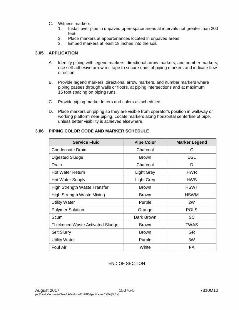
August 2017 15076-5 7310M10 pw://Carollo/Documents/Client/CA/Petaluma/7310M10/Specifications/15076 (BidSet)
C. Witness markers: 1. Install over pipe in unpaved open-space areas at intervals not greater than 200
feet. 2. Place markers at appurtenances located in unpaved areas. 3. Embed markers at least 18 inches into the soil.
3.05 APPLICATION
A. Identify piping with legend markers, directional arrow markers, and number markers; use self-adhesive arrow roll tape to secure ends of piping markers and indicate flow direction.
B. Provide legend markers, directional arrow markers, and number markers where piping passes through walls or floors, at piping intersections and at maximum 15 foot spacing on piping runs.
C. Provide piping marker letters and colors as scheduled.
D. Place markers on piping so they are visible from operator's position in walkway or working platform near piping. Locate markers along horizontal centerline of pipe, unless better visibility is achieved elsewhere.
3.06 PIPING COLOR CODE AND MARKER SCHEDULE
Service Fluid Pipe Color Marker Legend Condensate Drain Charcoal C
Digested Sludge Brown DSL
Drain Charcoal D
Hot Water Return Light Grey HWR
Hot Water Supply Light Grey HWS
High Strength Waste Transfer Brown HSWT
High Strength Waste Mixing Brown HSWM
Utility Water Purple 2W
Polymer Solution Orange POLS
Scum Dark Brown SC
Thickened Waste Activated Sludge Brown TWAS
Grit Slurry Brown GR
Utility Water Purple 3W
Foul Air White FA
END OF SECTION


August 2017 15082-1 7310M10 pw://Carollo/Documents/Client/CA/Petaluma/7310M10/Specifications/15082 (BidSet)
SECTION 15082
PIPING INSULATION
PART 1 GENERAL
1.01 SUMMARY
A. Section includes: Insulation for piping and related systems.
B. Related sections: 1. Section 01330 - Submittal Procedures. 2. Section 01600 - Product Requirements. 3. Section 01783 - Warranties and Bonds. 4. Section 02318 - Trenching. 5. Section 15050 - Common Work Results for Mechanical Equipment. 6. Section 15052 - Common Work Results for General Piping. 7. Section 15076 - Pipe Identification. 8. Section 15211 - Ductile Iron Pipe: AWWA C151. 9. Section 15284 - Copper Pipe: Pre-Insulated.
1.02 REFERENCES
A. ASTM International (ASTM): 1. A53 - Standard Specification for Pipe, Steel, Black and Hot-Dipped,
Zinc-Coated, Welded, and Seamless. 2. C177 - Standard Test Method for Steady-State Heat Flux Measurements and
Thermal Transmission Properties by Means of the Guarded-Hot-Plate Apparatus.
3. C518 - Standard Test Method for Steady-State Thermal Transmission Properties by Means of the Heat Flow Meter Apparatus.
4. C533 - Standard Specification for Calcium Silicate Block and Pipe Thermal Insulation.
5. C547 - Standard Specification for Mineral Fiber Pipe Insulation. 6. C552 - Standard Specification for Cellular Glass Thermal Insulation. 7. C795 - Standard Specification for Thermal Insulation for Use in Contact with
Austenitic Stainless Steel. 8. C929 - Standard Practice for Handling, Transporting, Shipping, Storage,
Receiving, and Application of Thermal Insulation Materials for Use in Contact with Austenitic Stainless Steel.
9. C1136 - Standard Specification for Flexible, Low Permeance Vapor Retarders for Thermal Insulation.
10. D1784 - Standard Specification for Rigid Poly(Vinyl Chloride) (PVC) Compounds and Chlorinated Poly(Vinyl Chloride) (CPVC) Compounds.
11. D2310 - Standard Classification of Machine-Made "Fiberglass" (Glass-Fiber-Reinforced-Thermosetting-Resin) Pipe.
12. E84 - Standard Test Method for Surface Burning Characteristics of Building Materials.
13. E96 - Standard Test Methods for Water Vapor Transmission of Materials.

August 2017 15082-2 7310M10 pw://Carollo/Documents/Client/CA/Petaluma/7310M10/Specifications/15082 (BidSet)
1.03 DEFINITIONS
A. Buried: Piping that is installed below buildings, foundations, or finish grade, either in soil or encased in concrete in soil.
B. Concealed: Piping above suspended ceilings and within walls, partitions, shafts, or service spaces and spaces not normally exposed to view but not buried.
C. Exterior: Piping that is installed under canopies, outside a building, or within a pipe trench or tunnel.
D. Flame spread and smoke density: Burning characteristics determined in accordance with ASTM E84. No units apply to value.
E. Interior: Piping that is installed inside a building.
F. K factor: Thermal conductivity determined in accordance with ASTM C177 or C518 and expressed in units of BTU-inch/hour-square feet -degrees Fahrenheit.
G. Mineral fiber: Fibers manufactured of glass, rock, or slag processed from a molten state, with or without a binder.
H. Water vapor permeance: Water vapor transmission determined in accordance with ASTM E96 and expressed in units of perm-inch.
1.04 SUBMITTALS
A. Submit as specified in Section 01330.
B. Product data: As specified in Section15050. 1. Insulation properties: Include K factor, thickness, density, operating
temperature limits, tensile strength, compressive strength, moisture absorption, flame spread, and smoke developed in accordance with ASTM E84 and corrosivity to stainless steel piping in accordance with ASTM C795.
2. Jacket properties: Include covering material, cover thickness, tensile strength, tear strength, permeability in accordance with ASTM E96, flame spread, and smoke developed in accordance with ASTM E84, closure type or devices, and accessories.
3. Insulating blankets: Include materials, performance characteristics, method of attaching to equipment, listing of locations where insulating blankets will be installed.
4. Pre-insulated ductile iron piping: In addition to information required for insulation and jacket as specified above and information required as specified in Section 15211 for ductile iron piping, include catalog cut sheets, specifications, installation instructions, backfill procedures, and dimensioned drawings for pre-insulated ductile iron piping system.
5. Manufacturer's application instructions: Include assembly and application drawings and detailed instructions.
6. Laboratory report: Provide certified laboratory report stating that insulation is not manufactured using chlorinated polymers and does not contain chlorides, bromides, sulfates, or fire-rated materials.

August 2017 15082-3 7310M10 pw://Carollo/Documents/Client/CA/Petaluma/7310M10/Specifications/15082 (BidSet)
C. Provide warranty as specified in Section 01783.
1.05 REGULATORY REQUIREMENTS
A. Projects located in California comply with California Energy Commission Energy Efficiency Standards for Residential and Non-Residential Buildings.
PART 2 PRODUCTS
2.01 PIPE INSULATION, GENERAL REQUIREMENTS
A. As specified in Section 01600.
B. Insulation thicknesses: Provide insulation thickness in inches in accordance with the following table. Insulation thickness shown is nominal. Manufacturing tolerance of 15 percent variation is permissible.
Required Insulation Thicknesses (inches)
Service Temperature Range as Designated in Insulation
Schedule at End of this Section
Nominal Pipe Diameters 1 inch and Less
1.25 to 2 inch
2.5 to 4 inch
5 to 10 inch
Over 10 inch
Above 200 degrees Fahrenheit 2.0 2.5 3.0 3.5 3.5 100 to 200 degrees Fahrenheit 1.5 1.5 1.5 2.0 2.5 40 to 100 degrees Fahrenheit 0.5 1.0 1.0 1.5 2.0 Below 40 degrees Fahrenheit 1.0 1.0 1.5 2.0 2.0 Heat Traced Pipes 1.0 1.0 1.0 1.5 2.0 Aeration Air Pipes 0.5 0.5 1.0 1.0 1.0
2.02 PIPE INSULATION
A. Insulation types: Provide in accordance with the insulation types listed and scheduled.
B. Insulation, Type 1: 1. Insulation material: Closed cell elastomeric insulation. 2. Manufacturers: One of the following or equal:
a. Armstrong World Industries, AP Armaflex. b. Apache Products Company, ISO-25.
3. Minimum temperature range: Minus 40 degrees Fahrenheit to plus 220 degrees Fahrenheit.
4. K factor at 75 degrees Fahrenheit: Not more than 0.27 BTU-inch/hour-square feet-degrees Fahrenheit.
5. Fire ratings: a. Flame spread: 25 or less. b. Smoke density: 50 or less for insulation thicknesses up to 1.5 inches.
6. Joints: Seal with manufacturer’s recommended contact adhesive to form continuous water barrier.

August 2017 15082-4 7310M10 pw://Carollo/Documents/Client/CA/Petaluma/7310M10/Specifications/15082 (BidSet)
C. Insulation, Type 2: 1. Insulation material: Preformed mineral fiberglass insulation made from glass
fibers bonded with a thermosetting resin. a. In accordance with ASTM C547, Class 1. b. Provide with factory installed vapor barrier.
1) Material: White kraft paper bound to aluminum foil in accordance with ASTM C1136, Type I.
2) Longitudinal lap seals: Pressure-sensitive, self-sealing longitudinal lap strip with factory applied adhesive.
3) Circumferential butt seals: 4-inch wide tape or similar properties or 4-inch wide overlap with adhesive seal.
4) Vapor barrier permeability: 0.02 perms or lower. 5) Vapor barrier flame spread rating: 25 or less.
2. Minimum temperature range: Minus 0 degrees Fahrenheit to plus 850 degrees Fahrenheit.
3. K factor at 75 degrees Fahrenheit: Not more than 0.23 BTU-inch/hour-square feet degrees Fahrenheit.
4. Maximum moisture absorption, volume percent: 5. 5. Manufacturers: One of the following or equal:
a. Owens-Corning Fiberglas Corp. b. Johns Manville. c. Knauf Fiber Glass.
D. Insulation, Type 3: 1. Insulation material: Rigid cellular glass in accordance with ASTM C552,
Type II. 2. Temperature range: Minus 450 degrees Fahrenheit to plus 900 degrees
Fahrenheit. 3. K factor at 75 degrees Fahrenheit: Not more than 0.32 BTU-inch/hour-square
feet-degrees Fahrenheit. 4. Minimum average density: 7.5 pounds per cubic foot. 5. Maximum moisture absorption, volume percent: 5. 6. Minimum compressive strength: 87 pounds per square inch. 7. Moisture permeability: 0.00 perm-inch. 8. Manufacturers: One of the following or equal:
a. Pittsburgh Corning Corporation, Foamglas. b. Cell-U-Foam Corporation, Ultra-CUF.
E. Insulation, Type 4: 1. Insulation material: Asbestos-free, rigid calcium silicate in accordance with
ASTM C533; Type I for process temperatures up to 1,200 degrees Fahrenheit. 2. K factor at 500 degrees Fahrenheit: 0.55 for Type I. 3. Maximum average (dry) density: 14.5 pounds per cubic foot. 4. Compressive strength: 100 pounds per square inch, to produce a 5-percent
compression. 5. Manufacturers: One of the following or equal: In accordance with ASTM C533
Type I: a. Industrial Insulation Group, LLC, Thermo-12 Gold.

August 2017 15082-5 7310M10 pw://Carollo/Documents/Client/CA/Petaluma/7310M10/Specifications/15082 (BidSet)
F. Insulation, Type 5: Pre-insulated ductile iron piping: 1. Service pipe:
a. Ductile iron pipe as specified in Section 15211 and with pressure class and joint type conforming to requirements outlined in the Piping Schedule in Section 15052.
b. Concentric to casing: 1) Maximum allowable deviation from centerline of service pipe:
a) 1/4-inch at casing center point and 1/16-inch at end seals. 2. Insulation: Factory applied polyurethane foam; K factor of 0.16 at 70 degrees
Fahrenheit, average density of 2.0 pounds per cubic foot, suitable for service temperatures up to 250 degrees Fahrenheit.
3. Insulation cover: a. Polyvinyl chloride cover pipe; in accordance with ASTM D1784, Class
12454-B. b. The minimum jacket thickness: Minimum of 2 percent of nominal casing
diameter and suitable for H-20 highway loading with 2 feet of cover. 4. Field joints:
a. Restrained push-on type field joints as specified in Sections 15052 and 15211.
b. Field joints, gaskets, and associated components suitable for service temperatures up to 200 degrees Fahrenheit.
c. Field joints set to compensate for expansion and contraction; lubricated with non-toxic lubricant; insulation sealed with compression rubber end seals.
d. Fittings field insulated with urethane foam insulation. Field insulation after successful completion of jointing and pressure testing. 1) Urethane foam insulation: Rigid urethane insulating material or
foamed-in-place urethane of the same density and thickness as the pre-insulated pipe section.
2) Sealing ring area and retaining grooves: Tape closed prior to foaming if a foam-in-place product is used.
3) Field insulation protected with a pre-molded PVC jacket that conforms to each insulated fitting.
4) Sleeve extenders extended between the pre-insulated pipe section and pre-molded PVC jacket and taped down per pre-insulated piping system manufacturer’s recommendations.
5) Field insulated fitting and pre-molded PVC jacket wrapped and sealed per pre-insulated piping system manufacturer’s recommendations. Sealing method to prevent ingress of moisture or debris.
e. Fittings factory fabricated and pre-insulated with urethane foam insulation. f. Protect the insulation with a PVC plastic jacket of the same thickness and
quality as that of the straight pipe. g. All miters on the PVC jacket at fittings welded by a thermal set welding
process to provide a continuous jacket integrity. h. Shrinkable sleeves for field joints compatible with the PVC jacket. i. Shrinkable sleeves fabricated from radiation cross-linked semi-rigid
polyethylene, coated on all inside surfaces with thixotropic adhesive designed to flow and provide a complete seal when heated.
j. After jointing and pressure testing, apply rigid urethane insulating material or foamed-in-place urethane of the same density and thickness as the pipe section to the joint area.

August 2017 15082-6 7310M10 pw://Carollo/Documents/Client/CA/Petaluma/7310M10/Specifications/15082 (BidSet)
k. Seal the insulation to the PVC jacket using heat shrinkable sleeves. l. Provide end seals suitable for service temperatures up to 200 degrees
Fahrenheit on ends of each section of pre-insulated pipe. m. Make the end seals watertight to protect the exposed insulation. n. The pre-insulated ductile iron piping system manufacturer to supply all
material used to insulate and seal field joints. 5. Thermal expansion:
a. Provide design and materials for expansion via [push-on] [slip-in] joints, loops, expansion ells, and other fittings as required to accommodate service pipe thermal expansion and contraction based on a temperature range of 40 degrees Fahrenheit ambient to 200 degrees Fahrenheit service temperature.
6. Manufacturers: One of the following or equal: a. Thermal Pipe Systems, Inc., Duc-Tite. b. Perma-Pipe, Dual-Guard DI.
2.03 INSULATION JACKETS
A. Jacket, Type 1: 1. Material: 28 ounces per square yard polyvinyl chloride on polyester fabric; total
thickness 0.028 inches minimum. 2. Fire rating: 25 maximum flame spread, smoke developed 50 or less. 3. Color: As selected by the Engineer from manufacturer's standard colors. 4. Overlap: 1-inch minimum at joints and fittings. 5. Joint seal: Self-sealing lap tape. 6. Fittings: Factory made with full thickness insulation. 7. Manufacturers: One of the following or equal:
a. Accessible Products, Techlite Insulation, 379 SSL Series.
B. Jacket, Type 2: 1. Material: Ultraviolet-resistant polyvinyl chloride jacketing, 20 mil minimum
thickness. 2. Fire rating: 25 maximum flame spread, smoke developed 50 or less. 3. Color: White. 4. Overlap: 1-inch minimum at joints and fittings. 5. Joint seal: PVC solvent welded or adhesive as recommended by the
manufacturer. 6. Fittings: Factory made with full thickness insulation. 7. Manufacturers: One of the following or equal:
a. Johns Manville, Zeston 2000 PVC. b. Proto Corp., LoSMOKE PVC. c. Speedline Smoke Safe PVC Jacketing System. d. Knauf Covering System.
C. Jacket, Type 3: 1. Material: Aluminum, Alloy 5005; 0.016-inch (26 gauge) minimum thickness. 2. Overlap: Overlap circumferential joints 4 inches minimum; overlap longitudinal
joints 1-inch minimum; longitudinal joints oriented to minimize water entry. 3. Bands: 0.5 inch wide, 0.0508 inch (16 gauge) thick aluminum, same alloy as
jacket or 0.0179 inch thick Type 304 stainless steel; install on 18-inch centers, uniformly spaced and at all fitting joints.
4. Joint seal: Apply waterproof adhesive at joints and overlaps.

August 2017 15082-7 7310M10 pw://Carollo/Documents/Client/CA/Petaluma/7310M10/Specifications/15082 (BidSet)
5. Fittings: Custom fit of same materials. 6. Manufacturers: One of the following or equal:
a. Childers Products. b. Premetco International.
2.04 VAPOR BARRIERS
A. Vapor barrier, Type 1: 1. Material: White kraft paper bound to aluminum foil in accordance with
ASTM C1136, Type 1. 2. Permeability: 0.02 perms or lower. 3. Maximum flame spread rating: 25. 4. Edge seal: Pressure-sensitive tape lap seal. 5. Circumferential joints: 4-inch wide tape or 4-inch overlap with adhesive seal.
B. Vapor barrier, Type 2: 1. Material: Mastic. 2. Manufacturers: One of the following or equal:
a. Benjamin Foster, No. 30-76. b. Insul-Coustic, No. I.C.-580. c. Foster Products, 36-10/46-10 Weatherite. d. Childers Products CP10/11 Vi-Acryl.
2.05 RELATED MATERIALS
A. Cover adhesive: Premium adhesive as recommended by the insulation cover supplier for heavy-duty service in corrosive, wet environments. Standard-duty adhesives are not permitted.
2.06 REMOVABLE INSULATING BLANKETS
A. In piping systems specified to be insulated, use removable insulating blankets for valves, meters, strainers, filters, catalytic converters, engine exhaust silencers, and other in-line piping appurtenances and equipment requiring periodic servicing.
B. Size limits: Use removable insulating blankets for equipment and piping appurtenances 3-inch in nominal size and larger. Insulate equipment and piping appurtenances less than 3-inch with molded sections of insulation or by field cutting insulation to conform to the shape of the component and to fit tightly around the component.
C. Manufacturers: One of the following, or equal: 1. Pittsburgh Corning, Temp-Mat. 2. Accessible Products, Thermazip 2000 Jacket. 3. Thermal Energy Products, Inc., Energy Wrap.
D. Low temperature insulating blankets rated up to 800 degrees Fahrenheit: 1. Use: For service temperatures up to 800 degrees Fahrenheit. 2. Insulation: Fiberglass fiber, K factor 0.27 at 75 degrees Fahrenheit. 3. Cover: 17-ounce fabric with both sides covered with silicone-impregnated
glass cloth suitable for temperatures up to 800 degrees Fahrenheit. 4. Cover fasteners: Use one of the following systems:
a. Grommets in the blanket and stainless steel wire.

August 2017 15082-8 7310M10 pw://Carollo/Documents/Client/CA/Petaluma/7310M10/Specifications/15082 (BidSet)
b. 1-inch wide straps with stainless steel rectangular ring buckles and Velcro on strap tail.
E. High temperature insulating blankets rated up to 1,400 degrees Fahrenheit: 1. Rated for sustained service temperatures up to 1,400 degrees Fahrenheit. 2. Insulation: Ceramic fiber, K factor 0.50 at 600 degrees Fahrenheit, insulation
material suitable for up to 2,300 degrees Fahrenheit, thickness to match adjacent piping insulation specified thickness.
3. Cover: 17-ounce silicone impregnated fiberglass cloth suitable for temperatures up to 1,400 degrees Fahrenheit.
4. Cover fasteners: Use one of the following systems: a. Grommets in the blanket and stainless steel wire. b. 1-inch wide straps with stainless steel rectangular ring buckles and Velcro
on strap tail.
2.07 SHIPPING
A. As specified in Section 01600.
PART 3 EXECUTION
3.01 DELIVERY, STORAGE, AND HANDLING
A. As specified in Section 01600.
B. Store insulation materials and accessories under cover and protected from moisture.
C. Handle and store insulation for use on stainless steel in accordance with ASTM C929.
3.02 PREPARATION
A. Pressure test piping and complete application of coating system before applying insulation.
B. When piping is to be heat traced, install and functionally test heat tracing before installation of insulation.
C. Before beginning installation of piping insulation, verify that the Engineer has accepted piping tests, pipe coating applications, and heat tracing tests.
3.03 INSULATION SCHEDULE
Service Designation(1) Location(2)
Insulation Type(3) Jacket Type(3)
Service Temp. °F(4)
Vapor Barrier
High Strength Waste Transfer (HSWT) Exterior 2 or 3 1 or 2 95-105 None
High Strength Waste Mix (HSWM) Exterior 2 or 3 1 or 2 95-105 None

August 2017 15082-9 7310M10 pw://Carollo/Documents/Client/CA/Petaluma/7310M10/Specifications/15082 (BidSet)
Service Designation(1) Location(2)
Insulation Type(3) Jacket Type(3)
Service Temp. °F(4)
Vapor Barrier
Notes: 1. Refer to Piping Schedule in Section 15052 for service designations. 2. Insulation jackets are not required for interior installations that are concealed. See definitions for
description of concealed locations. 3. Contractor may select from options listed. 4. Unless noted otherwise, use service temperature range provided in this table to establish
insulation thickness as required by Table in Article 2.01, Paragraph A. 5. Service temperature based on engine rating. Use Type I calcium silicate for exhaust temperatures
up to 1,000 degrees Fahrenheit; use Type II calcium silicate for exhaust temperatures above 1,000 degrees Fahrenheit.
6. Install insulation on all aeration air piping located within the Blower Building from the discharge of blowers to 10 feet above floor slab. Insulation is not required for aeration air piping that is installed higher than 10 feet above the floor slab.
7. Insulate all piping systems that are specified to be heat traced.
3.04 INSTALLATION
A. Install insulation and jacket materials in accordance with manufacturer's written instructions.
B. Pre-insulated ductile iron piping: 1. Install pre-insulated ductile iron piping in accordance with manufacturer’s
written instructions. 2. Bed piping and backfill around piping in accordance with manufacturer’s
written requirements, including all required hand tamping and backfill compaction. In case of conflict between Section 02318 and manufacturer’s requirements, the most stringent requirements govern.
C. Apply insulation in smooth, clean manner with tight and finished smooth joints. Fit insulation tightly against surfaces. Insulate each continuous run of pipe with full-length sections of insulation with a single piece cut to length to complete the run of pipe. Do not use cut pieces or scraps to complete the installation.
D. Butt longitudinal and circumferential insulation joints firmly together.
E. Maintain the integrity of vapor barrier jacketing. Do not use staples to hold vapor barrier overlaps in place.
F. Apply sealant or cement when previous applications of adhesives and cement have thoroughly dried.
G. Apply insulation to permit expansion or contraction of pipelines without damage to insulation or jacketing.
H. Fittings: 1. Insulate fittings by covering with mitered sections of insulation or utilize
factory-made prefabricated fitting shapes. 2. Terminate preformed pipe jackets or covering at sufficient distance from
flanges to permit removal of bolts. 3. Overlap flange and flanged fitting insulation on adjacent pipe covering by at
least 2 inches.
August 2017 15082-10 7310M10 pw://Carollo/Documents/Client/CA/Petaluma/7310M10/Specifications/15082 (BidSet)
I. Valves: 1. Insulate valves 3-inch in nominal size and larger with removable insulating
blankets. 2. Size blanket to extend up to packing gland only so that replacement of packing
does not require removal of insulating blanket.
J. Provide continuous insulation through and over pipe supports and provide protection saddles at supports.
K. Extend insulation against insulation end protection shields or covers so that insulation voids do not exist and provide watertight end seals and covers where insulation terminates.
L. Insulate pipeline strainers to permit removal of strainer basket without disturbing insulation on strainer body.
M. Provide continuous pipe insulation and covering through sleeves or openings in walls and floors. When buried pipe enters a building through a below grade wall or slab penetration, begin insulation system on interior side of penetration.
N. Apply premolded pipe insulation with extended legs when used on pipe traced with either tubing or electric cable type.
O. Thermally isolate all insulation closure locations (end caps, transitions, etc.) Type 1 or 2 jacket installation on piping with potential reach temperatures greater than 150 degrees Fahrenheit.
P. Apply piping identification on jackets as specified in Section 15076.
END OF SECTION

August 2017 15110-1 7310M10 pw://Carollo/Documents/Client/CA/Petaluma/7310M10/Specifications/15110 (BidSet)
SECTION 15110
COMMON WORK RESULTS FOR VALVES
PART 1 GENERAL
1.01 SUMMARY
A. Section includes: Basic requirements for valves.
B. Related sections: 1. Section 01330 - Submittal Procedures. 2. Section 01756 - Commissioning. 3. Section 01782 - Operation and Maintenance Data. 4. Section 09960 - High-Performance Coatings. 5. Section 15211 - Ductile Iron Pipe: AWWA C151.
1.02 REFERENCES
A. American Water Works Association (AWWA): 1. C111/A21.11 - Standard for Rubber-Gasket Joints for Ductile-Iron Pressure
Pipe Fittings.
B. ASTM International (ASTM): 1. A126 - Standard Specification for Gray Iron Casting for Valves, Flanges, and
Pipe Fittings. 2. A167 - Standard Specification for Stainless and Heat-Resisting Chromium-
Nickel Steel Plate, Sheet, and Strip. 3. A536 - Standard Specification for Ductile Iron Castings.
C. NSF International (NSF): 1. 61 - Drinking Water System Components - Health Effects.
D. Society for Protective Coatings (SSPC): 1. SP 7 - Brush-Off Blast Cleaning. 2. SP 10 - Near-White Blast Cleaning.
1.03 DESIGN REQUIREMENTS
A. Pressure rating: 1. Suitable for service under minimum working pressures of 150 pounds per
square inch gauge. 2. When a piping system is specified in the Piping Schedule to be tested at a
pressure greater than 150 pounds per square inch gauge, provide valves for that piping system with design working pressure which is sufficient to withstand the test pressure.
B. Valve to piping connections: 1. Valves 3 inch nominal size and larger: Flanged ends. 2. Valves less than 3 inch nominal size: Screwed ends.

August 2017 15110-2 7310M10 pw://Carollo/Documents/Client/CA/Petaluma/7310M10/Specifications/15110 (BidSet)
3. Plastic valves in plastic piping: a. Up to 2.5 inches: Provide solvent or heat welded unions. b. 3 inches and above: Provide solvent or heat welded flanges.
1.04 SUBMITTALS
A. Submit as specified in Section 01330.
B. Product data: 1. Submit the following information for each valve:
a. Valve type, size, pressure rating, Cv factor. b. Coatings. c. Power valve actuators:
1) Information on valve actuator including size, manufacturer, model number, limit switches, mounting; and motor enclosure, seating and unseating torque coefficient, dynamic torque, and bearing friction for calculation of maximum operating torque.
2) Complete wiring diagrams and control system schematics. d. Manual valve actuators:
1) Information on valve actuator including size, manufacturer, model number.
e. Certified drawings with description of component parts, dimensions, weights, and materials of construction.
f. Certifications of reference standard compliance: 1) Submit certification that the valves and coatings are suitable in
potable water applications in accordance with NSF 61. g. Clearly mark submittal information to show specific items, materials, and
accessories or options being furnished. h. Factory test data.
C. Provide vendor operation and maintenance manual as specified in Section 01782. 1. Furnish bound sets of installation, operation, and maintenance instructions for
each type of manual valve 4 inch in nominal size and larger, and all non-manual valves. Include information on valve operators.
D. Provide Manufacturer’s Certificate of Source Testing as specified in Section 01756.
E. Provide Manufacturer’s Certificate of Installation and Functionality Compliance as specified in Section 01756.
1.05 QUALITY ASSURANCE
A. Manufacturer qualifications: 1. Valves manufactured by manufacturers whose valves have had successful
operational experience in comparable service.
1.06 DELIVERY STORAGE AND HANDLING
A. Protect valves and protective coatings from damage during handling and installation; repair coating where damaged.
August 2017 15110-3 7310M10 pw://Carollo/Documents/Client/CA/Petaluma/7310M10/Specifications/15110 (BidSet)
PART 2 PRODUCTS
2.01 MATERIALS
A. Stainless steel: In accordance with ASTM A167, Type 316, or Type 304, UNS Alloy S31600 or S30400.
B. Valve and operator bolts and nuts: 1. Fabricated of stainless steel for the following installation conditions:
a. Submerged in sewage or water. b. In an enclosed space above sewage or water. c. In structures containing sewage or water, below top of walls. d. At openings in concrete or metal decks.
2. Where dissimilar metals are being bolted, use stainless steel bolts with isolation bushings and washers.
3. Underground bolts: Low-alloy steel in accordance with AWWA C111/A21.11.
C. Bronze and brass alloys: Use bronze and brass alloys with not more than 6 percent zinc and not more than 2 percent aluminum in the manufacture of valve parts; UNS Alloy C83600 or C92200 unless specified otherwise.
D. Valve bodies: Cast iron in accordance with ASTM A126, Class 30 minimum or ductile iron in accordance with ASTM A536, Grade 65-45-12 minimum unless specified otherwise.
2.02 INTERIOR PROTECTIVE LINING
A. When specified in the particular valve specification, provide valves with type of protective lining specified in the particular valve Specification.
B. Apply protective lining to interior, non-working surfaces, except stainless steel surfaces.
C. Lining types: 1. Fusion bonded epoxy:
a. Manufacturers: One of the following or equal: 1) 3-M Company, ScotchKote 134; certified to NSF 61 for drinking water
use. b. Clean surfaces in accordance with SSPC SP 7 or SP 10, as
recommended by epoxy manufacturer. c. Apply in accordance with manufacturer's published instructions. d. Lining thickness: 0.010 to 0.012 inches except that:
1) Lining thickness in grooves for gaskets: 0.005 inches. 2) Do not coat seat grooves in valves with bonded seat.
e. Quality control: 1) Lining thickness: Measured with a non-destructive magnetic type
thickness gauge. 2) Verify lining integrity with a wet sponge-testing unit operating at
approximately 60 volts, or as recommended by the lining manufacturer.
3) Consider tests successful when lining thickness meets specified requirements and when no pinholes are found.
August 2017 15110-4 7310M10 pw://Carollo/Documents/Client/CA/Petaluma/7310M10/Specifications/15110 (BidSet)
4) Correct defective lining disclosed by unsuccessful tests, and repeat test.
5) Repair pinholes with liquid epoxy recommended by manufacturer of the epoxy used for lining.
2. High solids epoxy: a. Product equivalent to high solids epoxy specified in Section 09960.
1) Certified in accordance with NSF 61 for drinking water use. 2) Interior: Coat valve interior with manufacturer's equivalent high
performance high solids epoxy coating system with a certifiable performance history for the service conditions and as approved by the Engineer. Manufacturer shall provide for approval, coating information sufficient to allow Engineer to assess equivalence to the specified high solids epoxy coating specified in Section 09960.
b. Clean surfaces to meet SP-7 or SP-10, or as recommended by coating manufacturer.
c. Quality control: After coating is cured, check coated surface for porosity with a holiday detector set at 1,800 volts, or as recommended by coating manufacturer. 1) Repair holidays and other irregularities and retest coating. 2) Repeat procedure until holidays and other irregularities are
corrected.
2.03 UNDERGROUND VALVES
A. Provide underground valves with flanged, mechanical, or other type of joint required for the type of pipe to which the valve is to be connected.
B. Coating and wrapping: 1. After installation, encase valves in 2 layers of polyethylene wrap as specified
for ductile iron piping in Section 15211. a. Ascertain that polyethylene wrapping does not affect operation of valve.
2.04 FIELD APPLIED COATING OF VALVE EXTERIOR
A. Match color and be compatible with manufacturer’s coating system and as specified in Section 09960. 1. When shop applied finish coating matches field applied coating on adjacent
piping, touch up shop coating in damaged areas in accordance with instructions recommended by the paint manufacturer.
2. When shop applied coating does not match field coating on adjacent piping, or when damage has occurred to the shop applied coating that requires more than touchup, blast clean valve surfaces or utilize other surface preparation recommended by the manufacturer of the coating material and apply the coating system used for coating adjacent piping.
2.05 VALVE BOXES
A. Provide cast-iron valve boxes at each buried valve to access valve and valve operators.
B. Do not support boxes on valve, valve operator, or pipe.

August 2017 15110-5 7310M10 pw://Carollo/Documents/Client/CA/Petaluma/7310M10/Specifications/15110 (BidSet)
C. Boxes: 1. 2-piece, fabricated of cast iron; provide cover, with asphalt varnish or enamel
protective coating. 2. Adjustable to grade, install centered around the upper portions of the valve
and valve operator.
D. Manufacturers: One of the following or equal: 1. Tyler Pipe Industries, Inc. 2. Neenah Foundry Company.
2.06 VALVE OPERATORS
A. Valve operator "Open" direction: Open counterclockwise.
B. Provide valves located below operating level or deck with extensions for key operation or floor stands and handwheels.
C. Provide manually operated valves located not more than 6 feet above the operating level with tee handles, wrenches, or handwheels. 1. Make the valve operator more conveniently accessible by rolling valves,
located more than 5 feet but less than 6 feet above the operating level, toward the operating side.
2. Secure tee handles and wrenches to the valve head or stem, except where a handle or wrench so secured constitutes a hazard to personnel; in which case, stow handle or wrench immediately adjacent to the valve on or in a suitable hanger, bracket, or receptacle.
D. Fit valves located more than 6 feet above operating level with chain operated handles or valve wheels. 1. Chains: Sufficient length to reach approximately 4 feet above the operating
level. 2. Where chains constitute a nuisance or hazard to operating personnel, provide
holdbacks or other means for keeping the chains out of the way.
E. Provide an operator shaft extension from valve or valve operator to finished grade or deck level when buried valves, and other valves located below the operating deck or level, are specified or indicated on the Drawings to be key operated; provide 2 inch square AWWA operating nut, and box and cover as specified, or a cover where a box is not required.
PART 3 EXECUTION
3.01 EXAMINATION
A. Preparation prior to installation: 1. Install valves after the required submittal on installation has been accepted. 2. Determine after flanged valves and flanged check valves are selected, the
face-to-face dimensions of flanged valves and flanged check valves.
B. Fabricate piping to lengths taking into account the dimensions of flanged valves and flanged check valves.

August 2017 15110-6 7310M10 pw://Carollo/Documents/Client/CA/Petaluma/7310M10/Specifications/15110 (BidSet)
3.02 INSTALLATION
A. Provide incidental work and materials necessary for installation of valves including flange gaskets, flange bolts and nuts, valve boxes and covers, concrete bases, blocking, and protective coating.
B. Where needed, furnish and install additional valves for proper operation and maintenance of equipment and plant facilities under the following circumstances: 1. Where such additional valves are required for operation and maintenance of
the particular equipment furnished by Contractor. 2. Where such additional valves are required as a result of a substitution or
change initiated by Contractor.
C. Install valves with their stems in vertical position above the pipe, except as follows: 1. Butterfly valves, gate valves aboveground, globe valves, ball valves, and angle
valves may be installed with their stems in the horizontal position. 2. Install buried plug valves with geared operators with their stems in a horizontal
position.
D. Install valves so that handles clear obstructions when the valves are operated from fully open to fully closed.
E. Place top of valve boxes flush with finished grade or as otherwise indicated on the Drawings.
F. Valves with threaded connections: 1. Install valves by applying wrench on end of valve nearest the joint to prevent
distortion of the valve body. 2. Apply pipe joint compound or Teflon tape on external (male) threads to prevent
forcing compound into valve seat area.
G. Valves with flanged connections: 1. Align flanges and gasket carefully before tightening flange bolts. 2. When flanges are aligned, install bolts and hand tighten. 3. Tighten nuts opposite each other with equal tension before moving to next pair
of nuts.
H. Valves with soldered connections: 1. Do not overheat connection to prevent damage to resilient seats and metal
seat rings. 2. Position valves in full open position before starting soldering procedure. 3. Apply heat to piping rather than to valve body.
3.03 COMMISSIONING
A. As specified in Section 01756 and this Section.
B. Manufacturer services from each manufacturer for all valves supplied: 1. Provide Manufacturer’s Certificate of Source Testing. 2. Provide Manufacturer’s Certificate of Installation and Functionality
Compliance.

August 2017 15110-7 7310M10 pw://Carollo/Documents/Client/CA/Petaluma/7310M10/Specifications/15110 (BidSet)
C. As specified elsewhere for specific valve types, sizes or actuators. 1. Source testing. 2. Manufacturers on site services for Owner Training, Installation Testing,
Functional Testing, and during the Process Operational Period.
END OF SECTION


August 2017 15111-1 7310M10 pw://Carollo/Documents/Client/CA/Petaluma/7310M10/Specifications/15111 (BidSet)
SECTION 15111
BALL VALVES
PART 1 GENERAL
1.01 SUMMARY
A. Section includes: Ball valves.
B. As specified in Section 15110.
C. Related sections: 1. Section 01330 - Submittal Procedures. 2. Section 01756 - Commissioning. 3. Section 01783 - Warranties and Bonds. 4. Section 09960 - High-Performance Coatings. 5. Section 13445A - Hydraulic and Pneumatic Cylinder Operators. 6. Section 13445B - Pneumatic Controllers and Control Valves. 7. Section 13447 - Electric Motor Actuators. 8. Section 15052 - Common Work Results for General Piping. 9. Section 15110 - Common Work Results for Process Valves.
1.02 REFERENCES
A. American Petroleum Institute (API): 1. 6D - Specification for Pipeline Valves (Steel Gate, Plug, Ball, and Check
Valves) - Gate Valves; Plug Valves; Ball Valves; Check Valves.
B. American Society of Mechanical Engineers (ASME): 1. B16.1 - Gray Iron Pipe Flanges and Flanged Fittings: Classes 25, 125, and
250. 2. B16.5 - Pipe Flanges and Flanged Fittings: NPS 1/2 through 24.
C. American Water Works Association (AWWA): 1. C507 - Standard for Ball Valves 6 Inch Through 48 Inch.
D. ASTM International (ASTM): 1. A48 - Standard Specification for Gray Iron Castings. 2. A216 - Standard Specification for Steel Castings, Carbon, Suitable for Fusion
Welding, for High-Temperature Service. 3. A351 - Standard Specification for Castings, Austenitic, for Pressure-Containing
Parts.
1.03 SYSTEM DESCRIPTION
A. General: Unless otherwise indicated on the Drawings use: 1. Metal body ball valves on metallic pipelines. 2. Plastic body ball valves on plastic pipelines.

August 2017 15111-2 7310M10 pw://Carollo/Documents/Client/CA/Petaluma/7310M10/Specifications/15111 (BidSet)
B. Do not use metal body ball valves in sodium hypochlorite or sodium bisulfite systems.
1.04 SUBMITTALS
A. Submit as specified in Section 01330.
B. Product data: As specified in Section 15110: 1. Metal body ball valves: 6 inches and larger only: Submit affidavit of compliance
in accordance with AWWA C507. 2. Sludge cake ball valves: Submit affidavit of satisfactory completion of shell test
and seat test. 3. Operation and maintenance manual.
C. Commissioning submittals: 1. Provide Manufacturer’s Certificate of Installation and Functionality Compliance
as specified in Section 01756.
1.05 WARRANTY
A. Provide warranty as specified in Section 01783.
PART 2 PRODUCTS
2.01 METAL BODY BALL VALVES, 6 INCH SIZE AND LARGER
A. Manufacturers: One of the following or equal: 1. DeZURIK/APCO: Metal seated valve. 2. Crane ChemPharma Energy: Resilient seated valve. 3. Henry Pratt Co.: Resilient seated valve.
B. General: 1. Type: Non-lubricated, resilient seated or metal seated and capable of sealing
in either flow direction. 2. In accordance with AWWA C507. 3. Stem packing: Manually adjustable while valve is under pressure. 4. ASME B16.1, Class 125 flanged ends.
C. Materials: 1. Body: ASTM A48 cast iron with 400 series Monel seats (metal seated valves
only) and integrally cast bronze bushed trunnions. 2. Ball: Type 304 or 316 stainless steel. 3. Seats: PTFE (resilient seated valves) or 300 series stainless steel (metal
seated valves). 4. Stem seals: PTFE or Viton.
D. Valve actuator: 1. Manually operated valves: Self-locking worm gear type actuator with position
indicator. Permanently lubricate gearing. Provide adjustable screws to stop travel at both open and closed positions.
2. Hydraulically operated valves: Provide hydraulic cylinder operator as specified in Section 13445A.

August 2017 15111-3 7310M10 pw://Carollo/Documents/Client/CA/Petaluma/7310M10/Specifications/15111 (BidSet)
3. Pneumatically operated valves: Provide pneumatic cylinder operator as specified in Section 13445B.
4. Electric motor operated valves: Provide electric motor operator as specified in Section 13447.
2.02 METAL BODY BALL VALVES, LESS THAN 6 INCH SIZE
A. Manufacturers: One of the following, or equal: 1. Apollo Valves as manufactured by Conbraco Industries, Inc. 2. Metso Automation/Jamesbury. 3. NIBCO, Inc. 4. Flow-Tek, Inc.
B. General: 1. Type: Non-lubricated, full port and capable of sealing in either direction. 2. End connections:
a. Threaded or solder ends for sizes 3-inch and smaller. b. Class 150 flanged for sizes larger than 3 inch.
1) Flanges: In accordance with ASME B16.1 standards. 3. Stem packing: Manually adjustable while valve is under pressure. 4. Shafts:
a. Rigidly connected to the ball by a positive means. 1) Design connection to transmit torque equivalent to at least
75 percent of the torsional strength of the shaft. 5. Handles: Stainless steel latch lock handle with vinyl grip and stainless steel nut
designed to open and close the valve under operating conditions. 6. Temperature limits: Suitable for operation between minus 20 and 350 degrees
Fahrenheit.
C. Materials: 1. Valves in copper lines: Bronze body. 2. Valves in steel and ductile iron piping: Ductile iron or cast steel body. 3. Valves in stainless steel piping: Stainless steel body, material type to match
piping material as specified in Section 15052. 4. Ball: Type 304 or 316 stainless steel, Type 316 in digester gas applications. 5. Seats: PTFE. 6. Stem seals: PTFE or Viton. 7. Bearings: Self-lubricated, corrosion resistant material that will not contaminate
potable water. 8. Valves for combustible fluid applications (digester gas, natural gas, fuel oil,
etc.) must be of fire safe design.
2.03 PLASTIC BODY BALL VALVES
A. Manufacturers: One of the following or equal: 1. Asahi America. 2. Chemtrol Division, NIBCO, Inc. 3. Plast-O-Matic Valves, Inc. 4. CRANE ChemPharma & Energy 5. Georg Fischer Piping Systems.
B. General: 1. Type: Non-lubricated and capable of sealing in either flow direction.

August 2017 15111-4 7310M10 pw://Carollo/Documents/Client/CA/Petaluma/7310M10/Specifications/15111 (BidSet)
2. End connections: True union; solvent or heat welded to piping. 3. Operator handle: Lever.
C. Materials: 1. Body: Polyvinyl chloride (PVC). 2. Ball: Polyvinyl chloride (PVC). 3. Seats: PTFE (Teflon). 4. O-rings: EPDM.
PART 3 EXECUTION
3.01 INSTALLATION
A. General: Install each type of valve in accordance with manufacturers' printed instructions.
B. Special techniques: 1. PVC ball valves for hypochlorite service:
a. Provide valve with factory drilled 0.125-inch hole in the upstream side of the ball.
b. Provide an engraved plastic tag permanently attached to the valve stem stating "One side of ball drilled for hypochlorite service".
3.02 FIELD APPLIED COATING OF VALVE EXTERIOR
A. Match color and be compatible with manufacturer’s coating system and as specified in Section 09960. 1. When shop applied finish coating matches field applied coating on adjacent
piping, touch up shop coating in damaged areas in accordance with instructions recommended by the paint manufacturer.
2. When shop applied coating does not match field coating on adjacent piping, or when damage has occurred to the shop applied coating that requires more than touchup, blast clean valve surfaces or utilize other surface preparation recommended by the manufacturer of the coating material and apply the coating system used for coating adjacent piping.
3.03 COMMISSIONING
A. As specified in Section 01756 and this Section.
B. Manufacturer services: 1. Provide certificates:
a. Manufacturer's Certificate of Installation and Functionality Compliance.
C. Functional testing: 1. Valves:
a. Test witnessing: Witnessed. b. Conduct pressure and leak test, as specified in Section 15110.
END OF SECTION

August 2017 15112-1 7310M10 pw://Carollo/Documents/Client/CA/Petaluma/7310M10/Specifications/15112 (BidSet)
SECTION 15112
BUTTERFLY VALVES
PART 1 GENERAL
1.01 SUMMARY
A. Section includes: Butterfly valves: 1. As specified in Section 15110.
B. Related sections: 1. Section 01330 - Submittal Procedures. 2. Section 01756 - Commissioning. 3. Section 01783 - Warranties and Bonds. 4. Section 09960 - High-Performance Coatings. 5. Section 15110 - Common Work Results for Valves. 6. Section 15211 - Ductile Iron Pipe: AWWA C151.
1.02 REFERENCES
A. American Society of Mechanical Engineers (ASME): 1. B16.1 - Cast Iron Pipe Flanges and Flanged Fittings, Classes 25, 125 and
250. 2. B16.5 - Pipe Flanges and Flanged Fittings, NPS 1/2 through NPS 24.
B. American Water Works Association (AWWA): 1. C110 - Standard for Ductile-Iron and Gray-Iron Fittings. 2. C504 - Rubber-Seated Butterfly Valves. 3. C540 - Standard for Power-Actuating Devices for Valves and Sluice Gates. 4. C550 - Protective Interior Coatings for Valves & Hydrants. 5. C606 - Standard for Grooved and Shouldered Joints.
C. ASTM International (ASTM): 1. A126 - Standard Specification for Gray Iron Castings for Valves, Flanges, and
Pipe Fittings. 2. A216 - Standard Specification for Steel Castings, Carbon, Suitable for Fusion
Welding, for Higher-Temperature Service. 3. A276 - Standard Specification for Stainless Steel Bars and Shapes. 4. A351 - Standard Specification for Castings, Austenitic, for Pressure-Containing
Parts. 5. A395 - Standard Specification for Ferritic Ductile Iron Pressure-Retaining
Castings for Use at Elevated Temperatures. 6. A479 - Standard Specification for Stainless Steel Bars and Shapes for Use in
Boilers and Other Pressure Vessels. 7. A515 - Standard Specification for Pressure Vessel Plates, Carbon Steel, for
Intermediate - and Higher-Temperature Service. 8. A516 - Standard Specification for Pressure Vessel Plates, Carbon Steel, for
Moderate - and Lower-Temperature Service. 9. A536 - Standard Specification for Ductile Iron Castings.

August 2017 15112-2 7310M10 pw://Carollo/Documents/Client/CA/Petaluma/7310M10/Specifications/15112 (BidSet)
10. A564 - Standard Specification for Hot-Rolled and Cold-Finished Age-Hardening Stainless Steel Bars and Shapes.
11. A743 - Standard Specification for Castings, Iron-Chromium, Iron-Chromium-Nickel, Corrosion Resistant, for General Application.
12. A890 - Standard Specification for Castings, Iron-Chromium-Nickel-Molybdenum Corrosion-Resistant, Duplex (Austenitic/Ferritic) for General Application.
13. B462 - Standard Specification for Forged or Rolled UNS N06030, UNS N06022, UNS N06035, UNS N06200, UNS N06059, UNS N10362, UNS N06686, UNS N08020, UNS N08024, UNS N08026, UNS N08367, UNS N10276, UNS N10665, UNS N10675, UNS N10629, UNS N08031, UNS N06045, UNS N06025, UNS R20033 Alloy Pipe Flanges, Forged Fittings, and Valves and Parts for Corrosive High-Temperature Service.
14. B584 - Standard Specification for Copper Alloy Sand Castings for General Applications.
15. B691 – Standard Specification for Iron-Nickel-Chromium-Molybdenum Alloys (UNS N08366 and UNS N08367) Rod, Bar, and Wire.
16. D429 - Standard Test Methods for Rubber Property-Adhesion to Rigid Substrate.
D. Compressed Gas Association (CGA): 1. Standard G-4.1 - Cleaning Equipment for Oxygen Service.
E. NSF International (NSF): 1. Standard 61 - Drinking Water System Components - Health Effects.
F. United States Code of Federal Regulations (CFR): 1. 21 - Food and Drugs.
1.03 SYSTEM DESCRIPTION
A. Design requirements: 1. General purpose AWWA butterfly valves:
a. Design standard: Provide valves designed and manufactured in accordance with AWWA C504.
b. Class: 1) Provide butterfly valves in accordance with AWWA Class 150B,
unless otherwise specified. 2) Provide butterfly valves in accordance with AWWA Class 250B in
piping systems with test pressure greater than 150 pounds per square inch and less than 250 pounds per square inch.
2. High pressure butterfly valves: a. Piping systems designed for operating pressures greater than 250 pounds
per square inch and less than 450 pounds per square inch: Provide ASME B16.5, Class 300 high pressure valves.
3. Industrial class butterfly valves: a. Industrial class butterfly valves capable of 150 pounds per square inch
leak tight shut off. 4. Stainless steel butterfly valves:
a. Stainless steel butterfly valves capable of a minimum of 100 pounds per square inch leak tight shut off and with special cleaning, packaging, and handling.

August 2017 15112-3 7310M10 pw://Carollo/Documents/Client/CA/Petaluma/7310M10/Specifications/15112 (BidSet)
B. Usage: 1. Provide and install butterfly valve types as outlined in the Butterfly Valve
Application Schedule at the end of this Section.
C. Design requirements for all butterfly valves with power actuating devices: 1. Design valves and actuators for maximum operating torque, in accordance
with and using safety factors required in AWWA C540, using the following values: a. Maximum water velocity: 16 feet per second with valve fully open. b. Maximum pressure differential across the closed valve equal to the
pressure class designation. c. Coefficient for seating and unseating torque, dynamic torque, and bearing
friction in accordance with valve manufacturer's published recommendations.
2. Valve disc: Seat in an angular position of 90 degrees to the pipe axis and rotate an angle of 90 degrees between fully open and fully closed positions: a. Do not supply valves with stops or lugs cast with or mechanically secured
to the body of the valve for limiting the disc travel. 3. Unacceptable thrust bearings: Do not provide valves with thrust bearings
exposed to the fluid in the line and consisting of a metal bearing surface in rubbing contact with an opposing metal bearing surface.
D. Performance requirements: 1. Tight shutoff at the pressure rating of the valve with pressure applied in either
direction. 2. Suitable for the following service conditions:
a. Throttling. b. Frequent operation. c. Operation after long periods of inactivity. d. Installation in any position and flow in either direction.
1.04 SUBMITTALS
A. Submit as specified in Section 01330
B. Product data: 15110 1. For general purpose AWWA butterfly valves, include description of the method
of attachment of the disc edge to the valve disc. 2. Interior epoxy coatings: Affidavit of compliance attesting that epoxy coatings
applied to interior surfaces of butterfly valves comply with all provisions in accordance with AWWA C550.
3. Certification, for valves and coatings in contact with potable water, that the products used are suitable for contact with drinking water in accordance with NSF Standard 61.
C. Commissioning submittals:
D. Provide Manufacturer’s Certificate of Installation and Functionality Compliance as specified in Section 01756
1.05 WARRANTY
A. Provide warranty as specified in Section 01783.

August 2017 15112-4 7310M10 pw://Carollo/Documents/Client/CA/Petaluma/7310M10/Specifications/15112 (BidSet)
PART 2 PRODUCTS
2.01 GENERAL PURPOSE AWWA BUTTERFLY VALVES
A. Manufacturers: One of the following or equal: 1. DeZURIK/Sartell Model BAW. 2. Henry Pratt Company.
B. Valve body: 1. Material: Cast iron, ASTM A126, Grade B, or ductile iron, ASTM A536, Grade
65-45-12. 2. Body design:
a. Flanged body valves: 1) Usage: Comply with limitations specified in the Butterfly Valve
Application Schedule. 2) Flanges: In accordance with ASME B16.1 Class 125 flanges for
Class 150B valves, in accordance with ASME B16.1 Class 250 flanges for Class 250B valves.
b. Mechanical joint body valves: 1) Usage: Comply with limitations specified in the Butterfly Valve
Application Schedule. 2) Mechanical joint design: In accordance with AWWA C110. 3) When mechanical joint body valves are used, incorporate valve into
thrust restraint analysis as specified in Section 15211. Utilize test pressure on one side of valve and zero pressure on the opposite side of the valve. Restrain pipe joints on both sides of valve as determined by thrust analysis calculations.
c. Grooved end body valves: 1) Usage: Butterfly valves with grooved ends may be used in piping
systems specified in the Piping Schedule to have grooved end joints. Comply with additional limitations specified in the Butterfly Valve Application Schedule.
2) Grooved end joint design: In accordance with AWWA C606.
C. Disc: 1. Material: Cast iron or ductile iron with Type 316 stainless steel edge that
matches seat in valve body. 2. Secure valve disc to shaft by means of smooth-sided, taper or dowel pins,
Type 316 stainless steel, or Monel. 3. Extend pins through shaft and mechanically secure in place.
D. Shaft and bearings: 1. Shaft design:
a. Valves 20-inch and less: 1 piece, through disc design. b. Valves greater than 20-inch size: 2 piece, stub shaft design.
2. Shaft seal: Vee type, chevron design. 3. Shaft material for Class 150B valves: Type 316 stainless steel, ASTM A276. 4. Shaft material for Class 250B valves: Type 17-4 pH stainless steel,
ASTM A564. 5. Shaft bearings: Self-lubricating sleeve type:
a. Valves 20-inch and less: Nylatron.

August 2017 15112-5 7310M10 pw://Carollo/Documents/Client/CA/Petaluma/7310M10/Specifications/15112 (BidSet)
b. Valves greater than 20-inch size: Teflon with stainless steel or fiberglass backing.
E. Seats: 1. Seat materials:
a. In low-pressure air applications: EPDM. b. In all other applications: EPDM.
2. For valves 20 inches in nominal size and smaller, bond or vulcanize seat into the valve body.
3. For valves 24 inches in nominal size and larger, retain seats mechanically or by adhesive: a. Mechanical retainage: Retain seat by a clamping ring with segmented
clamping ring locks with adjusting locking screws. 1) Clamping ring, ring locks, and adjusting locking screws: Type 316
stainless steel. 2) Provide means to prevent ring locks and screws used to retain seats
from loosening due to vibration or cavitation. b. Adhesive retainage: Inset the seat within a groove in the valve body and
retain in place with epoxy injected behind the seat so that the seat expands into the body.
c. Do not provide valves with seats retained by snap rings or spring-loaded retainer rings.
4. Resilient seat: Withstand 75 pound per inch pull when tested in accordance with ASTM D429, Method B.
F. Valve packing: 1. Valves 4 inch to 48 inch nominal size: Self-adjusting V-type packing or
chevron-type packing. NBR or EPDM to match seat material. 2. Valves 54 inch nominal size and larger: Adjustable V-type packing with bronze
packing gland or self-adjusting V-type packing. NBR or EPDM to match seat material.
2.02 HIGH PRESSURE BUTTERFLY VALVES
A. Manufacturers: One of the following or equal: 1. Crane Flowseal. 2. Neles-Jamesbury.
B. Valve body: 1. Material: Carbon steel ASTM A515 or A516, Grade 70, or ASTM A216, WCB. 2. Body design: Flanged, in accordance with ASME B16.5, Class 300
dimensions. Wafer and lugged style valves may not be used for high-pressure service.
C. Disc: 1. Offset disc. 2. Material: Type 316 stainless steel, ASTM A351, Grade CF-8M.
D. Shaft and bearings: 1. Shaft: Type 316 stainless steel, ASTM A479 or Type 17-4 PH stainless steel,
ASTM A564. 2. Shaft bearings: Self-lubricating sleeve type; Teflon with stainless steel or
fiberglass backing.

August 2017 15112-6 7310M10 pw://Carollo/Documents/Client/CA/Petaluma/7310M10/Specifications/15112 (BidSet)
E. Disc pins: Secure valve disc to shaft by means of solid, smooth-sided, taper or dowel pins, Type 316 stainless steel or Monel: 1. Extend pins through shaft and mechanically secure in place.
F. Seats: 1. Material: Teflon, or Teflon with titanium back-up ring. 2. Seat retainer ring:
a. If used on sizes above 20-inch: Type 316 stainless steel with stainless steel fasteners.
b. Type 316 stainless steel for digester gas applications. c. For all such valves, bond the seat to the retention ring.
G. Valve shaft packing: Teflon, chevron type design. Field adjustable and field replaceable.
2.03 INDUSTRIAL CLASS BUTTERFLY VALVES
A. Manufacturers: One of the following or equal: 1. SPX/DeZURIK Style BOS. 2. Tyco-Keystone Figure AR2.
B. Valve body: 1. Pressure rating: 150 pounds per square inch, minimum. 2. Material: Cast iron, ASTM A126, Class B or Ductile Iron, ASTM A395, Grade
60/40/18. 3. Body design: Lugged style body with drilled and tapped boltholes in
accordance with ASME B16.1, Class 125 and Class 150 flange drilling dimensions.
C. Disc: 1. Materials:
a. Air and water service: Cast iron, ASTM A126, Class B or Ductile Iron, ASTM A536, Grade 65/45/12 or Type 316 stainless steel, ASTM A351, Grade CF8M.
b. Natural gas and digester gas service: Type 316 stainless steel, ASTM A351, Grade CF8M.
2. Disc edge: Nickel-plated when cast iron or ductile iron disc is used.
D. Shaft and bearings: 1. Shaft: Type 316 stainless steel, ASTM. 2. Shaft bearings: Self-lubricating sleeve type, Teflon with stainless steel or
fiberglass backing.
E. Disc pins: Secure valve disc to shaft by means of solid, smooth-sided, taper or dowel pins, Type 316 stainless steel: 1. Extend pins through shaft and mechanically secure in place.
F. Seats: 1. Material:
a. Natural gas and digester gas applications: Neoprene or Buna N. b. All other applications: EPDM.

August 2017 15112-7 7310M10 pw://Carollo/Documents/Client/CA/Petaluma/7310M10/Specifications/15112 (BidSet)
2. Seat retention ring, if used on larger sizes: Type 316 stainless steel or bronze, ASTM B584, with stainless steel fasteners. For all such valves, bond the seat to the retention ring.
G. Valve shaft packing: 1. Natural gas and digester applications: Neoprene or Buna N. 2. All other applications: EPDM or Teflon.
2.04 THERMOPLASTIC BUTTERFLY VALVES (1-1/2 TO 16-INCHES)
A. Manufacturers: One of the following, or equal: 1. ASAHI, Type 56. 2. Hayward. 3. Georg Fischer Piping System. 4. Plast-O-Matic Valves, Inc.
B. Valve Body: 1. Material: PVC, CPVC, PVDF. 2. Body Design: Lugged, wafer style body with drilled and tapped bolt holes to
match ASME B 16.1, Class 125 and Class 150 flanged drilling dimensions.
C. Disc: 1. Disc shall be offset. 2. Material: PVC, CPVC, PVDF.
D. Stem and stem older: 1. Stem: Type 316 stainless steel. 2. Stem holder: Type 304 stainless steel.
E. Seats: 1. Material: EPDM. 2. O-rings: EPDM.
2.05 COATING
A. Shop coat interior and exterior metal surfaces of valves, except as follows: 1. Interior machined surfaces. 2. Surfaces of gaskets and elastomeric seats and stem seals. 3. Bearing surfaces. 4. Stainless steel surfaces and components.
B. Coating material for potable water applications: 1. Formulate interior coating material from materials in accordance with CFR 21,
AWWA C550, and NSF 61. 2. Submit affidavit of compliance attesting that epoxy coatings applied to interior
surfaces of butterfly valves in accordance with CFR 21, AWWA C550, and NSF 61.
C. Interior surfaces: 1. Interior surfaces, except for valves used in low-pressure air service: High
solids epoxy. 2. Interior surfaces of valves used in low-pressure air service: High temperature
coating for range of 150 to 350 degrees Fahrenheit.

August 2017 15112-8 7310M10 pw://Carollo/Documents/Client/CA/Petaluma/7310M10/Specifications/15112 (BidSet)
D. Exterior surfaces: 1. Exterior surfaces of valves, actuators, and accessories coating in accordance
with Section 09960 with the following coating types: a. Submerged valves: High solids epoxy. b. Buried valves: Coal tar epoxy. c. Other valves: High solids epoxy with polyurethane topcoat.
2. Polished and machined surfaces: Apply rust-preventive compound, a. Manufacturers: One of the following or equal:
1) Houghton, Rust Veto 344. 2) Rust-Oleum, R-9.
E. Coating materials: 1. High solids epoxy and coal tar epoxy:
a. Products: As specified in Section 09960: 1) Coating product in contact with potable water must be in accordance
with AWWA C550 and NSF 61. 2. High temperature coating: As specified in Section 09960 and in accordance
with AWWA C550. 3. Rust-preventive compound:
a. Manufacturers: One of the following or equal: 1) Houghton, Rust Veto 344. 2) Rust-Oleum, R-9.
F. Field applied coatings of valve exterior: 1. Match color and be compatible with manufacturer’s coating system and as
specified in Section 09960. a. When shop applied finish coating matches field applied coating on
adjacent piping, touch up shop coating in damaged areas in accordance with instructions recommended by the paint manufacturer.
b. When shop applied coating does not match field coating on adjacent piping, or when damage has occurred to the shop applied coating that requires more than touchup, blast clean valve surfaces or utilize other surface preparation recommended by the manufacturer of the coating material and apply the coating system used for coating adjacent piping.
PART 3 EXECUTION
3.01 INSTALLATION
A. Install valves with valve shafts horizontal, unless a vertical shaft is required to suit a particular installation, and unless a vertical shaft is indicated on the Drawings.
B. Install pipe spools or valve spacers in locations where butterfly valve disc travel may be impaired by adjacent pipe lining, pipe fittings, valves, or other equipment.
3.02 BUTTERFLY VALVE APPLICATION SCHEDULE
A. Acceptable butterfly valve types and body styles are listed in the Butterfly Valve Application Schedule provided at the end of this Section. Furnish and install butterfly valves in accordance with this Schedule.

August 2017 15112-9 7310M10 pw://Carollo/Documents/Client/CA/Petaluma/7310M10/Specifications/15112 (BidSet)
3.03 COMMISSIONING AND PROCESS START-UP REQUIREMENTS
A. As specified in Section 01756 and this Section.
B. Manufacturer services: 1. Provide certificates:
a. Manufacturer’s Certificate of Installation and Functionality Compliance.
C. Functional testing: 1. Valves:
a. Test witnessing: Witnessed. b. Conduct pressure and leak test, as specified in Section 15110
BUTTERFLY VALVE APPLICATION SCHEDULE Valve Type and Style Acceptable Applications
General Purpose AWWA Butterfly Valves – Flanged Body Design
Aboveground or submerged in the following service applications only: - Acceptable in all service applications except
oxygen and ozone service and high-pressure service.
- May be used in buried applications when required by the specified piping system.
General Purpose AWWA Butterfly Valves – Mechanical Joint Body Design
Buried in the following service applications only: - Acceptable in all service applications except
oxygen and ozone service and high-pressure service.
General Purpose AWWA Butterfly Valves – Lugged Body Design
Aboveground in the following service applications only: - Aeration Air Systems
General Purpose AWWA Butterfly Valves – Wafer (not lugged) Body Design Not allowed.
General Purpose AWWA Butterfly Valves – Grooved End Body Design
Aboveground, in sizes 20-inch and less, with piping system test pressure less than 100 psi, and in the following service applications only: - Acceptable in all service applications, except
oxygen and ozone service, where piping for that service is specified in the Piping Schedule to have grooved end joints.
High Pressure Butterfly Valves – Flanged Body Design
Service applications with piping system test pressure greater than 250 psi. Acceptable in aboveground and buried installations.
High Pressure Butterfly Valves – Wafer or Lugged Wafer Body Design Not allowed.
Industrial Class Butterfly Valves – Lugged Body Design
Aboveground in the following service applications only: - Aeration Air Systems - Natural Gas Systems - Digester Gas Systems - Chilled and Hot Water Systems

August 2017 15112-10 7310M10 pw://Carollo/Documents/Client/CA/Petaluma/7310M10/Specifications/15112 (BidSet)
BUTTERFLY VALVE APPLICATION SCHEDULE Valve Type and Style Acceptable Applications
Industrial Class Butterfly Valves – Wafer (not lugged) Body Design Not allowed.
Stainless Steel Butterfly Valves - Lugged Body Design
Aboveground in the following service applications only: - Oxygen Systems - Ozone Systems
Stainless Steel Butterfly Valves – Wafer (not lugged) Body Design Not allowed.
END OF SECTION

August 2017 15114-1 7310M10 pw://Carollo/Documents/Client/CA/Petaluma/7310M10/Specifications/15114 (BidSet)
SECTION 15114
CHECK VALVES
PART 1 GENERAL
1.01 SUMMARY
A. Section includes: Check valves.
B. As specified in Section 15110.
C. Related sections: 1. Section 01330 - Submittal Procedures. 2. Section 01756 - Commissioning. 3. Section 01783 - Warranties and Bonds. 4. Section 09960 - High-Performance Coatings. 5. Section 15110 - Common Work Results for Valves.
1.02 REFERENCES
A. American Society of Mechanical Engineers (ASME): 1. B16.1 - Gray Iron Pipe Flanges and Flanged Fittings: Classes 25, 125, and
250. 2. B16.5 - Pipe Flanges and Flanged Fittings: NPS 1/2 through NPS 24 Inch
Standard.
B. American Water Works Association (AWWA): 1. C508 - Standard for Swing-Check Valves for Waterworks Service 2 Inch
Through 24 Inch (50-mm Through 600-mm) NPS.
C. ASTM International (ASTM): 1. A126 - Standard Specification for Gray Iron Castings for Valves, Flanges, and
Pipe Fittings. 2. A313 - Standard Specification for Stainless Steel Spring Wire. 3. A536 - Standard Specification for Ductile Iron Castings. 4. B582 - Standard Specification for Nickel-Chromium-Iron-Molybdenum-Copper
Alloy Plate, Sheet, and Strip. 5. B584 - Standard Specification for Copper Alloy Sand Castings for General
Applications.
1.03 SYSTEM DESCRIPTION
A. Design requirements: 1. Check valves: When not otherwise specified as indicated on the Drawings,
provide check valves suitable for service as follows: a. In either horizontal or vertical position. b. Suitable for service working pressures up to 150 pounds per square inch
gauge.
August 2017 15114-2 7310M10 pw://Carollo/Documents/Client/CA/Petaluma/7310M10/Specifications/15114 (BidSet)
1.04 SUBMITTALS
A. Submit as specified in Section 01330.
B. Product data: As specified in Section 15110.
C. Commissioning submittals: 1. Provide Manufacturer’s Certificate of Installation and Functionality Compliance
as specified in Section 01756.
1.05 WARRANTY
A. Provide warranty as specified in Section 01783.
PART 2 PRODUCTS
2.01 CENTER GUIDE (SILENT) CHECK VALVES
A. Manufacturers: One of the following or equal: 1. APCO, Model Number 600. 2. Crispin, Series GC.
B. Valve design: 1. Center-guided, spring-loaded plug. 2. Replaceable seat and plug. 3. Shaft guide bushing. 4. Non-slam, silent shutoff. 5. Flanged body.
C. Materials: 1. Body: Cast iron, ASTM A126 Grade B, or Type 316 stainless steel,
ASTM A313. 2. Plug and seat: Bronze, ASTM B584 C83600. 3. Spring: Stainless steel, ASTM A313 Type 316. 4. Shaft and bushing: Bronze, ASTM B584 C83600. 5. Seat: Buna-N or EPDM.
2.02 SWING CHECK VALVES
A. Valves 1/4 inch through 3 inch: 1. Manufacturers: One of the following or equal:
a. Crane Valve Company, Number 36. b. Lunkenheimer Company, Figure 554Y.
2. Valve design: a. Threaded joints. b. Y-pattern body with integral seat. c. Hinged disc. d. Access to valve seat for regrinding without disassembly of piping.
3. Materials: a. Body, cap, hinge, and disc: Bronze.

August 2017 15114-3 7310M10 pw://Carollo/Documents/Client/CA/Petaluma/7310M10/Specifications/15114 (BidSet)
B. Valves 4 inch through 24 inch: 1. Manufacturers: One of the following or equal:
a. Kennedy, Figure 106LW or M&H, Model 159. b. Mueller Company, Model A-2600. c. APCO Model 250. d. Crispin SWL Series.
2. Valve design: a. In accordance with AWWA C508. b. Constructed to permit top entry and removal of internal components
without removing the valve. c. Equipped with outside lever and weight.
3. Materials: a. Body: Cast iron, ASTM A126 Class B or ASTM A536 Grade 65-45-12
Ductile Iron. b. Disc:
1) Valve disc shall be ASTM A126 cast iron, ASTM A536 ductile iron, or ASTM B584 bronze.
2) 4-inch valves: Bronze or stainless steel rings and seats. 3) 6 inches and larger valves: Bronze-faced or stainless steel rings and
seats. 4) Rubber seat Buna-N or Manufacturer's selection for HSW
applications. c. Hinge pins: Stainless steel.
2.03 OIL-CUSHIONED SWING CHECK VALVES
A. Manufacturers: One of the following or equal: 1. Crispin, Series SWC-BB. 2. APCO, Swing-Check, Series 6000B.
B. Valve design 8 inches to 66 inches: 1. Counterweighted:
a. Single counterweight on sizes 8 inches to 12 inches (right side). b. Dual counterweights on sizes 14 inches and larger.
2. Rubber-seated and driptight. 3. Totally enclosed oil-dampening chambers with adjustment for closing speed. 4. Bottom-mounted hydraulic oil cushion system:
a. System shall permit free open, but positive non-slam controlled closure of the disc. 1) Hydraulic cushion shall make contact with the disc during the last
10 percent of closure to control the disc until shutoff. b. System shall be externally adjustable to suit operating conditions. c. System shall be totally enclosed and removable without need to remove
the entire valve. 1) Oil system shall be totally independent from the main line to prevent
corrosion or contamination to the process water. 5. Materials:
a. Valve body, cover, and disc: Ductile Iron ASTM A536 Grade 65-45-12. b. Disc seat: Bolted in replaceable seat, EPDM.
1) Disc attachment design: a) Single top-shaft disc mount with machined pin, (no bolts and
nuts attachments on the disc are acceptable).
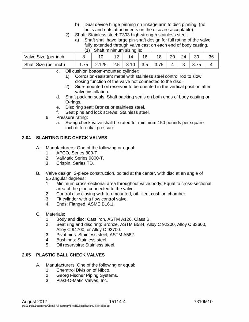
August 2017 15114-4 7310M10 pw://Carollo/Documents/Client/CA/Petaluma/7310M10/Specifications/15114 (BidSet)
b) Dual device hinge pinning on linkage arm to disc pinning, (no bolts and nuts attachments on the disc are acceptable).
2) Shaft: Stainless steel: T303 high-strength stainless steel: a) Shaft shall have large pin-shaft design for full rating of the valve
fully extended through valve cast on each end of body casting. (1) Shaft minimum sizing is:
Valve Size (per inch 8 10 12 14 16 18 20 24 30 36
Shaft Size (per inch) 1.75 2.125 2.5 3 10 3.5 3.75 4 3 3.75 4 c. Oil cushion bottom-mounted cylinder:
1) Corrosion-resistant metal with stainless steel control rod to slow closing function of the valve not connected to the disc.
2) Side-mounted oil reservoir to be oriented in the vertical position after valve installation.
d. Shaft packing seals: Shaft packing seals on both ends of body casting or O-rings.
e. Disc ring seat: Bronze or stainless steel. f. Seat pins and lock screws: Stainless steel.
6. Pressure rating: a. Swing check valve shall be rated for minimum 150 pounds per square
inch differential pressure.
2.04 SLANTING DISC CHECK VALVES
A. Manufacturers: One of the following or equal: 1. APCO, Series 800-T. 2. ValMatic Series 9800-T. 3. Crispin, Series TD.
B. Valve design: 2-piece construction, bolted at the center, with disc at an angle of 55 angular degrees: 1. Minimum cross-sectional area throughout valve body: Equal to cross-sectional
area of the pipe connected to the valve. 2. Control disc closing with top-mounted, oil-filled, cushion chamber. 3. Fit cylinder with a flow control valve. 4. Ends: Flanged, ASME B16.1.
C. Materials: 1. Body and disc: Cast iron, ASTM A126, Class B. 2. Seat ring and disc ring: Bronze, ASTM B584, Alloy C 92200, Alloy C 83600,
Alloy C 94700, or Alloy C 93700. 3. Pivot pins: Stainless steel, ASTM A582. 4. Bushings: Stainless steel. 5. Oil reservoirs: Stainless steel.
2.05 PLASTIC BALL CHECK VALVES
A. Manufacturers: One of the following or equal: 1. Chemtrol Division of Nibco. 2. Georg Fischer Piping Systems. 3. Plast-O-Matic Valves, Inc.

August 2017 15114-5 7310M10 pw://Carollo/Documents/Client/CA/Petaluma/7310M10/Specifications/15114 (BidSet)
B. Valves: Ball type: 1. Material: Polyvinyl chloride. 2. End connection: Double-or single-union-type. 3. Seals: Viton.
C. Valve body material: 1. Polyvinyl chloride (PVC), chlorinated polyvinyl chloride (CPVC), Polypropylene
(PP) or polyvinylidene fluoride (PVDF), as best suited for each individual service condition.
D. Union connections material: 1. NPT or socket ends conforming to ASME B16.5 pipe flanges and flange
fittings, Class 150.
E. Seats and seals material: 1. EPDM, Buna-N, or Viton.
F. Maximum inlet pressure rating: 1. PVC, CPVC, or PVDF: 150 pound per square inch at 77 degrees Fahrenheit. 2. PP: 100 pounds per square inch at 77 degrees Fahrenheit.
PART 3 EXECUTION
3.01 INSTALLATION
A. Flapper-type check valves: 1. Install with proper orientation of flow direction arrow on valve body. 2. When installed in horizontal pipelines, mount with shaft on vertical locations. 3. When mounted in a vertical pipeline, directly downstream of an elbow, mount
with the shaft perpendicular to the outermost portion of the elbow. 4. Mount on downstream side of discharge silencer when used on positive
displacement and centrifugal blowers.
3.02 FIELD APPLIED COATING OF VALVE EXTERIOR
A. Match color and be compatible with manufacturer’s coating system and as specified in Section 09960. 1. When shop applied finish coating matches field applied coating on adjacent
piping, touch up shop coating in damaged areas in accordance with instructions recommended by the paint manufacturer.
2. When shop applied coating does not match field coating on adjacent piping, or when damage has occurred to the shop applied coating that requires more than touchup, blast clean valve surfaces or utilize other surface preparation recommended by the manufacturer of the coating material and apply the coating system used for coating adjacent piping.
3.03 COMMISSIONING
A. As specified in Section 01756 and this Section.

August 2017 15114-6 7310M10 pw://Carollo/Documents/Client/CA/Petaluma/7310M10/Specifications/15114 (BidSet)
B. Manufacturer services: 1. Provide certificates:
a. Manufacturer's Certificate of Installation and Functionality Compliance.
C. Functional testing: 1. Valves:
a. Test witnessing: Witnessed. b. Conduct pressure and leak test, as specified in Section 15110.
END OF SECTION
August 2017 15116-1 7310M10 pw://Carollo/Documents/Client/CA/Petaluma/7310M10/Specifications/15116 (BidSet)
SECTION 15116
PLUG VALVES
PART 1 GENERAL
1.01 SUMMARY
A. Section includes: 1. Non-lubricated plug valves. 2. Lubricated plug valves. 3. Multi-port plug valves.
B. Related sections: 1. Section 01330 - Submittal Procedures. 2. Section 01600 - Product Requirements. 3. Section 01756 - Commissioning. 4. Section 01782 - Operation and Maintenance Data. 5. Section 01783 - Warranties and Bonds. 6. Section 09960 - High-Performance Coatings. 7. Section 15050 - Common Work Results for Mechanical Equipment. 8. Section 15110 - Common Work Results for Valves. 9. Section 17950 - Testing, Calibration, and Commissioning.
1.02 REFERENCES
A. American Water Works Association (AWWA): 1. C517 - Resilient-Seated Cast Iron Eccentric Plug Valves. 2. C606 - Grooved and Shouldered Joints.
B. ASTM International (ASTM): 1. A126 - Standard Specification for Gray Iron Castings for Valves, Flanges, and
Pipe Fittings. 2. A536 - Standard Specification for Ductile Iron Castings.
1.03 SUBMITTALS
A. Submit as specified in Section 01330 and 15110. 1. Product data. 2. Shop drawings. 3. Calculations.
B. Vendor operation and maintenance manual as specified in Section 01782.
C. Commissioning submittals: 1. Provide Manufacturer’s Certificate of Source Testing as specified in
Section 01756: a. Interior coating.
2. Provide Manufacturer’s Certificate of Installation and Functionality Compliance as specified in Section 01756.

August 2017 15116-2 7310M10 pw://Carollo/Documents/Client/CA/Petaluma/7310M10/Specifications/15116 (BidSet)
1.04 WARRANTY
A. Provide warranty as specified in Section 01783.
PART 2 PRODUCTS
2.01 GENERAL
A. As specified in Section 15110.
2.02 NON-LUBRICATED PLUG VALVES
A. Manufacturers: Sole source to match existing: 1. DeZurik, "PEC".
B. Design: 1. Type: Non-lubricated eccentric type, in accordance with AWWA C517. 2. Plug face: Resilient material that operates satisfactorily at a temperature of
180 degrees Fahrenheit continuous and 215 degrees Fahrenheit intermittent, except for valves in compressed air or digester gas service. a. Valves in compressed air service: Resilient material suitable for
continuous duty at 250 degrees Fahrenheit. b. Valves in digester gas service: Resilient material suitable for petroleum or
digester gas at continuous duty at 180 degrees Fahrenheit. 3. Compression washer: Provide flat compression washer made of Teflon, or of a
material having equal physical characteristics on valve stem between plug and bonnet.
4. Stem seals: Provide stem seals serviceable without unbolting the valve bonnet assembly.
5. Grit excluders: Provide PTFE grit excluders at upper plug journals to prevent entry of foreign solids in bearing area.
6. Clearly mark valves to indicate their open and closed positions. 7. Provide valves with ends as required by piping details indicated on the
Drawings. a. Grooved end body valves:
1) Usage: Plug valves with grooved ends may be used in piping systems specified in the Piping Schedule to have grooved end joints and as indicated on the Drawings.
2) Grooved end joint design: In accordance with AWWA C606. 8. The interference between the plug face and body seat, with the plug in the
closed position, shall be externally adjustable in the field with the valve in the line under the specified rated pressure.
9. Port areas for valves through 20 inches shall be at least 80 percent of full pipe are and at least 70 percent for valves 24 inches and greater.
10. Valves and gear actuators for buried or submerged service shall have seals on all shafts and gaskets on the valve and actuator covers to prevent the entry of water. Actuator mounting brackets for buried or submerged service shall be totally enclosed and shall have gasket seals. All exposed nuts, bolts, springs, and washers shall be stainless steel.

August 2017 15116-3 7310M10 pw://Carollo/Documents/Client/CA/Petaluma/7310M10/Specifications/15116 (BidSet)
C. Materials: 1. Body and plug: ASTM A126, Class B, cast-iron, with plug face of neoprene
Buna N or material suitable for the intended service as specified under paragraph "Design" above.
2. Body seats in valves 3 inch size and larger: Provide with overlay of not less than 90-percent nickel and minimum thickness of 1/8 inch on surfaces contacting the plug face.
3. Stem bearing and bottom bearing: Type 316 stainless steel. 4. Internal parts, except the body and plug: Type 316 stainless steel or Nickel. 5. Exposed nuts, bolts, and washers: Zinc plated. Exception: Exposed nuts,
bolts, and washers for buried service: Stainless steel.
2.03 LUBRICATED PLUG VALVES
A. Manufacturers: One of the following or equal: 1. Nordstrom. 2. Walworth.
B. Type: Semi-steel tapered plug valves.
C. Design: 1. Plug removable through top of valve. 2. Combined lubricant screw and grease gun fitting, of the type where the
pressure of the grease can be used to raise the plug slightly off its seat.
D. Where indicated on the Drawings or specified, provide plug valves with high head extension and floor stand with indicator. Provide worm gear-operated valves with worm shaft extension and floor stand, and with indicator supplied by manufacturer of plug valve: 1. Equip floor stands serving plug valves with individual operating wrenches.
2.04 MULTI-PORT PLUG VALVES FOR SLUDGE SERVICE
A. Manufacturers: Sole source to match existing: 1. DeZurik, PTW, for 3-way valve, and PFW for 4-way valve.
B. Design: Non-lubricated tapered plug type including plugs faced with neoprene, body of cast iron, and stainless steel bearings in the upper and lower journal areas.
C. Furnish valves with single, double, or transfer style plug as indicated on the Drawings or as required.
2.05 VALVE OPERATORS
A. Furnish valves with an operating wrench or worm gear operator: 1. Equip valves 4 inch nominal size and smaller with a lever operator. 2. Equip valves 6 inch nominal size and larger with a worm gear operator.
2.06 COATING
A. Coat and test interior metal surfaces as specified in Section 15110.
B. Coat exterior metal surfaces as specified in Section 09960.

August 2017 15116-4 7310M10 pw://Carollo/Documents/Client/CA/Petaluma/7310M10/Specifications/15116 (BidSet)
C. Field applied coating of valve exterior: 1. Match color and be compatible with manufacturer’s coating system and as
specified in Section 09960. a. When shop applied finish coating matches field applied coating on
adjacent piping, touch up shop coating in damaged areas in accordance with instructions recommended by the paint manufacturer.
b. When shop applied coating does not match field coating on adjacent piping, or when damage has occurred to the shop applied coating that requires more than touchup, blast clean valve surfaces or utilize other surface preparation recommended by the manufacturer of the coating material and apply the coating system used for coating adjacent piping.
2.07 SHIPMENT, SPARE PARTS, MAINTENANCE PRODUCTS, AND SPECIAL TOOLS
A. As specified in Section 01600.
PART 3 EXECUTION
3.01 INSTALLATION
A. Install valves as specified in Section 15110 and the manufacturer’s instructions. 1. Unless differently indicated on the Drawings install valves so that in the closed
position the pressure in the pipeline applies a seating head on the valves. 2. Install valves so that in the open position the plug is located in the top half of
the valve body.
B. For valves requiring lubrication: Lubricate and fill extended lubricant pipes with lubricant suitable for service intended.
3.02 COMMISSIONING
A. As specified in Section 01756 and this Section.
B. Manufacturer services: 1. Provide certificates:
a. Manufacturer’s Certificate of Installation and Functionality Compliance.
C. Functional testing: 1. Valves:
a. Test witnessing: Witnessed. b. Conduct pressure and leak test as specified in Section 15110.
END OF SECTION

August 2017 15117-1 7310M10 pw://Carollo/Documents/Client/CA/Petaluma/7310M10/Specifications/15117 (BidSet)
SECTION 15117
SPECIALTY VALVES
PART 1 GENERAL
1.01 SUMMARY
A. Section includes: Specialty valves.
B. As specified in Section 15110.
C. Related sections: 1. Section 01330 - Submittal Procedures. 2. Section 01756 - Commissioning. 3. Section 01783 - Warranties and Bonds. 4. Section 15082 - Piping Insulation. 5. Section 15110 - Common Work Results for Valves.
1.02 REFERENCES
A. American Society of Civil Engineers (ASCE): 1. 25 - Earthquake-Actuated Automatic Gas Shutoff Devices.
B. American Society of Mechanical Engineers (ASME): 1. B16.42 - Ductile Iron Pipe Flanges and Flanged Fittings: Classes 150 and 300.
C. American Water Works Association (AWWA): 1. C511 - Standard for Reduced Pressure-Principle Backflow-Prevention
Assembly. 2. C800 - Underground Service Line Valves & Fittings (Also Included: Collected
Standards For Service Line Materials).
D. ASTM International (ASTM): 1. A48 - Standard Specification for Gray Iron Castings. 2. A126 - Standard Specification for Gray Iron Casting for Valves, Flanges, and
Pipe Fittings. 3. A276 - Standard Specification for Stainless Steel Bars and Shapes. 4. A536 - Standard Specification for Ductile Iron Castings. 5. B584 - Standard Specification for Copper Alloy Sand Castings for General
Application. 6. D2000 - Standard Classification System for Rubber Products in Automotive
Applications.
E. National Electrical Manufacturers Association (NEMA): 1. 250 - Enclosures for Electrical Equipment (1000 V Maximum).
1.03 DEFINITIONS
A. NEMA Type 4 enclosure in accordance with NEMA 250.

August 2017 15117-2 7310M10 pw://Carollo/Documents/Client/CA/Petaluma/7310M10/Specifications/15117 (BidSet)
1.04 SUBMITTALS
A. Submit as specified in Section 01330.
B. Product data: As specified in Section 15110.
C. Commissioning submittals: 1. Backflow preventer certification. 2. Provide Manufacturer’s Certificate of Installation and Functionality Compliance
as specified in Section 01756.
1.05 WARRANTY
A. Provide warranty as specified in Section 01783.
PART 2 PRODUCTS
2.01 SOLENOID VALVES
A. 2-way solenoid valves: 1. Manufacturers: One of the following or equal:
a. Automatic Switch Company, Series 8210. b. Skinner Electric Valve Division, Series C.
B. 3-way solenoid valves: 1. Manufacturers: One of the following or equal:
a. Automatic Switch Company, Series 8320. b. Skinner Electric Valve Division, Type A4.
C. 4-way solenoid valves: 1. Manufacturers: One of the following or equal:
a. Automatic Switch Company, Bulletin 8344. b. Skinner Electric Valve Division, Series V9.
D. Design: 1. Valves: Suitable for service under the following conditions:
a. Fluid: 3W. b. Temperature of fluid: 70 degrees Fahrenheit. c. Piping test pressure: 180 pounds per square inch gauge.
2. Unless otherwise indicated on the Drawings, provide valves that meet the following requirements: a. Minimum NEMA Type 4 enclosure. b. 120 VAC operation. c. Suitable for use as indicated on the Drawings. d. Minimum Class F coil insulation.
3. 2-way valves: Furnish with openings of size equal to or larger than the nominal size designation of the valve.
4. Furnish with manual/bypass operators.
E. Materials: 1. Body: Brass or bronze. 2. Seats: Resilient material.

August 2017 15117-3 7310M10 pw://Carollo/Documents/Client/CA/Petaluma/7310M10/Specifications/15117 (BidSet)
PART 3 EXECUTION
3.01 INSTALLATION
A. Install as specified in Section 15110 in accordance with manufacturer's published instructions.
B. Install sensing line insulation as specified in Section 15082.
C. Plastic body diaphragm valves for sodium hypochlorite service: 1. When valves are installed horizontally, install valves with valve stem position
rotated as necessary such that no internal valve obstruction prevents the passage of vapors traveling along the top of adjacent piping from traveling through the valve.
3.02 COMMISSIONING
A. As specified in Section 01756 and this Section.
B. Manufacturer services: 1. Provide certificates:
a. Manufacturer’s Certificate of Installation and Functionality Compliance. 2. As specified in Section 15110.
END OF SECTION


August 2017 15118-1 7310M10 pw://Carollo/Documents/Client/CA/Petaluma/7310M10/Specifications/15118 (BidSet)
SECTION 15118
PRESSURE REDUCING AND PRESSURE RELIEF VALVES
PART 1 GENERAL
1.01 SUMMARY
A. Section includes: Pressure reducing and pressure relief valves for water, air, sludge and chemical service.
B. As specified in Section 15110.
C. Related sections: 1. Section 01330 - Submittal Procedures. 2. Section 01756 - Commissioning. 3. Section 01783 - Warranties and Bonds. 4. Section 09960 - High-Performance Coatings. 5. Section 15110 - Common Work Results for Valves.
1.02 REFERENCES
A. American Society of Mechanical Engineers (ASME): 1. B16.42 - Ductile Iron Pipe Flanges and Flanged Fittings: Classes 150 and 300.
B. ASTM International (ASTM): 1. A48 - Standard Specification for Gray Iron Castings. 2. A536 - Standard Specification for Ductile Iron Castings.
C. Underwriters Laboratories, Inc. (UL).
1.03 SUBMITTALS
A. Submit as specified in Section 01330.
B. Product data: As specified in Section 15110.
C. Commissioning submittals: 1. Provide Manufacturer’s Certificate of Installation and Functionality Compliance
as specified in Section 01756.
1.04 WARRANTY
A. Provide warranty as specified in Section 01783.

August 2017 15118-2 7310M10 pw://Carollo/Documents/Client/CA/Petaluma/7310M10/Specifications/15118 (BidSet)
PART 2 PRODUCTS
2.01 WATER PRESSURE REDUCING VALVES
A. Water pressure reducing valves, 2 1/2 inches and smaller: 1. Manufacturers: One of the following or equal:
a. Watts Regulator, Series LF223. b. Wilkins, 500 Series.
2. Direct operated, single seat type pressure reducing valve. 3. Materials:
a. Body and spring cover: Bronze. b. Valve seat: Series 300 stainless steel. c. Diaphragm: Buna Nitrile. d. Disk: Buna Nitrile.
B. Water pressure reducing valves, 3 inches and larger: 1. Manufacturers: One of the following, or equal:
a. Watts ACV Series 115. b. Cla-Val Model 90-01.
2. Design: a. Pilot controlled, hydraulically operated, diaphragm actuated, globe
patterned valve. b. Rated for 125 pounds per square inch gauge. c. Pilot line: Equipped with a strainer. d. Flanges: 150 pound rating, in accordance with ASME B16.42.
3. Materials: a. Body and cover: Cast iron ASTM A48 or Ductile Iron ASTM A536. b. Valve trim: Bronze. c. Pilot control: Cast bronze with Series 303 stainless steel trim. d. Diaphragm: Neoprene.
2.02 AIR PRESSURE REGULATING VALVES
A. Air pressure regulating valves for instrument air systems: 1. Manufacturers: One of the following, or equal:
a. Fisher Controls Company, Series 67CFR. b. Fairchild Industrial Products Company, Model 65A.
2. Design: a. Inlet pressure rating: Not less than 250 pounds per square inch gauge. b. Inlet and outlet ports: Tapped, 1/4-inch diameter. c. Internal pressure relief capability for minor seat leakage. d. Integral 40 micron filter. e. Drain valve at low point of body. f. Provide pressure gauge integrally mounted on the valve:
1) Gauge units: Pounds per square inch gauge. 2) Gauge range: Upper end of range approximately 150 percent of
output pressure. 3. Materials:
a. Body: Aluminum. b. Diaphragm and O-rings: Nitrile. c. Filter element: Stainless steel.

August 2017 15118-3 7310M10 pw://Carollo/Documents/Client/CA/Petaluma/7310M10/Specifications/15118 (BidSet)
4. Output pressure: a. As required for the application as determined by the manufacturer of the
instrument receiving the regulated air. b. Pressure range: As follows for the required output pressure:
1) Output pressure 20 pounds per square inch gauge, range 1 to 30. 2) Output pressure 30 pounds per square inch gauge, range 1 to 60. 3) Output pressure 40 pounds per square inch gauge, range 1 to 60.
2.03 SLUDGE PRESSURE RELIEF VALVES
A. Sludge pressure relief valves: 1. Manufacturers: One of the following or equal:
a. GA Industries, Inc., Figure Number 525-RD. b. Valve and Primer Corporation.
2. Component elements: Include body, disc, seating face, shaft, attached counterweight arms and lever, and cushion chamber.
3. Design: a. Provide valves that open immediately when the system pressure exceeds
the load setting of the counterweights, and close slowly at an adjustable speed upon return of system pressure to normal.
b. Set counterweights to open and relieve at a pressure 10 pounds per square inch greater than the pressure developed by the pump under normal operating conditions.
c. Cushion chamber: Attached externally to the side of the valve body and constructed with a piston operating in a chamber with valve operation without hammering action: 1) Cushioning:
a) By oil stored in an oil reservoir attached by piping and fittings to the cushion chamber.
b) Provide anti-freeze hydraulic oil as required. 2) Design cushion chamber to allow adjustment of closing speed.
4. Materials: a. Body: Heavy cast iron or cast steel. b. Disc: Welded steel. c. Seating face: EPDM. d. Shaft and cushion chamber: Bronze or steel.
2.04 PRESSURE RELIEF VALVES FOR CHEMICAL SERVICE
A. Manufacturers: One of the following or equal: 1. Plast-O-Matic, Series RVT, RVDT or TRVDT. 2. Asahi/America. 3. Georg Fischer Piping Systems.
B. Materials: 1. Valve body: CPVC or PVC. 2. U-cup seals:
a. Polymer service: Viton. b. Hypochlorite service: Viton. c. Caustic service: EPDM. d. Sodium Bisulfite: EPDM.
3. Adjusting bolt, locknut, control spring and fasteners: stainless steel.

August 2017 15118-4 7310M10 pw://Carollo/Documents/Client/CA/Petaluma/7310M10/Specifications/15118 (BidSet)
C. Design: 1. Pressure rating: Not less than 150 pounds per square inch. 2. In-line or angle pattern design, size as indicated on the Drawings. 3. End connections:
a. 1 inch and smaller: Threaded. b. Larger than 1 inch: Flanged.
4. Relief set point: a. Externally adjustable without removing valve from piping system. b. Set valve to open at 10 pounds per square inch more than pump
discharge pressure at operating point, or as indicated on the Drawings.
PART 3 EXECUTION
3.01 INSTALLATION
A. Install as specified in Section 15110.
3.02 FIELD APPLIED COATING OF VALVE EXTERIOR
A. Match color and be compatible with manufacturer’s coating system and as specified in Section 09960: 1. When shop applied finish coating matches field applied coating on adjacent
piping, touch up shop coating in damaged areas in accordance with instructions recommended by the paint manufacturer.
2. When shop applied coating does not match field coating on adjacent piping, or when damage has occurred to the shop applied coating that requires more than touchup, blast clean valve surfaces or utilize other surface preparation recommended by the manufacturer of the coating material and apply the coating system used for coating adjacent piping.
3.03 COMMISSIONING
A. As specified in Section 01756 and this Section.
B. Manufacturer services: 1. Provide certificates:
a. Manufacturer's Certificate of Installation and Functionality Compliance.
C. Functional testing: 1. Valves:
a. Test witnessing: Witnessed. b. Conduct pressure and leak test as specified in Section 15110.
END OF SECTION
August 2017 15119-1 7310M10 pw://Carollo/Documents/Client/CA/Petaluma/7310M10/Specifications/15119 (BidSet)
SECTION 15119
AIR AND VACUUM RELIEF VALVES
PART 1 GENERAL
1.01 SUMMARY
A. Section includes: Air release valves, air and vacuum valves, and air vents.
B. As specified in Section 15110.
C. Related sections: 1. Section 01330 - Submittal Procedures. 2. Section 01756 - Commissioning. 3. Section 01783 - Warranties and Bonds. 4. Section 09960 - High-Performance Coatings. 5. Section 15110 - Common Work Results for Valves.
1.02 REFERENCES
A. American Society of Mechanical Engineers (ASME). 1. B16.1 - Gray Iron Pipe Flanges and Flanged Fittings: Classes 25, 125, and
250. 2. B16.5 Pipe Flanges and Flanged Fittings: NPS 1/2 through 24.
B. American Water Works Association (AWWA).
C. ASTM International (ASTM): 1. A126 - Standard Specification for Gray Iron Castings for Valves, Flanges, and
Pipe Fittings. 2. A240 - Standard Specification for Chromium and Chromium-Nickel Stainless
Steel Plate, Sheet, and Strip for Pressure Vessels and for General Applications.
3. A270 - Standard Specification for Seamless and Welded Austenitic Stainless Steel Sanitary Tubing.
4. B584 - Standard Specification for Copper Alloy Sand Castings for General Applications.
1.03 SUBMITTALS
A. Submit as specified in Section 01330.
B. Product data: As specified in Section 15110.
C. Commissioning submittals: 1. Provide Manufacturer’s Certificate of Installation and Functionality Compliance
as specified in Section 01756.

August 2017 15119-2 7310M10 pw://Carollo/Documents/Client/CA/Petaluma/7310M10/Specifications/15119 (BidSet)
1.04 WARRANTY
A. Provide warranty as specified in Section 01783.
PART 2 PRODUCTS
2.01 COMBINATION AIR VALVES, WATER SERVICE
A. Manufacturers: One of the following or equal: 1. Valve and Primer Corporation, DeZurik/APCO, Series 140C. 2. Multiplex Manufacturing Company, Crispin UL Series.
B. Design: 1. Operation: Automatic exhaust of large quantities of air from pipelines during
filling and draining and release of accumulated air while pipeline is under pressure.
2. Utilize compound lever system in conjunction with large and small orifices. 3. Internal parts removable through top cover without removing valve from
pipeline. 4. Pressure rating: 150 pounds per square inch. 5. Inlet: Screwed, 2-inch size.
C. Materials: 1. Body: Cast iron. 2. Float: Type 316 stainless steel. 3. Needle: Buna-N. 4. Lever frame: Cast iron or Delrin.
2.02 AIR RELEASE VALVES, SEWAGE SERVICE
A. Manufacturers: Sole source to match existing: 1. ARI, Model to match existing.
B. Design: 1. Operation: Release accumulated air in sewage pipelines operating under
pressure. After entrained air escapes through the orifice, the orifice is plugged by a needle mounted on a compound lever mechanism.
2. Internal components removable through top cover without removing valve from pipeline.
3. Pressure rating: 150 pounds per square inch. 4. Orifice size: 1/4 inch diameter. 5. Connections: Threaded, 2-inch diameter inlet and threaded, 1/2-inch diameter
outlet.
C. Accessories: 1. Inlet shutoff valve. Utilize eccentric plug valve. 2. 2 blowoff valves for backflushing. 3. 10 feet of hose with quick disconnect couplings.
D. Materials: 1. Body: Cast iron. 2. Float: Type 316 stainless steel.

August 2017 15119-3 7310M10 pw://Carollo/Documents/Client/CA/Petaluma/7310M10/Specifications/15119 (BidSet)
3. Needle: Buna-N.
PART 3 EXECUTION
3.01 INSTALLATION
A. Install as specified in Section 15110 and manufacturer’s instructions.
B. Install air release valves and air and vacuum valves with suitable discharge lines to nearest drainage system.
3.02 FIELD APPLIED COATING OF VALVE EXTERIOR
A. Match color and be compatible with manufacturer’s coating system and as specified in Section 09960. 1. When shop applied finish coating matches field applied coating on adjacent
piping, touch up shop coating in damaged areas in accordance with instructions recommended by the manufacturer.
2. When shop applied coating does not match field coating on adjacent piping, or when damage has occurred to the shop applied coating that requires more than touchup, remove existing coating by abrasive blast cleaning and apply the coating system used for coating adjacent piping in accordance with Section 09960. a. Submerged valves: SP-5 White Metal Blast cleaning. b. Other valves: SP-10 Near-white blast cleaning.
3.03 COMMISSIONING
A. As specified in Section 01756 and this Section.
B. Manufacturer services: 1. Provide certificates:
a. Manufacturer's Certificate of Installation and Functionality Compliance.
C. Functional testing: 1. Valves:
a. Test witnessing: Witnessed. b. Conduct pressure and leak test as specified in Section 15110.
END OF SECTION

August 2017 15120-1 7310M10 pw://Carollo/Documents/Client/CA/Petaluma/7310M10/Specifications/15120 (BidSet)
SECTION 15120
PIPING SPECIALTIES
PART 1 GENERAL
1.01 SUMMARY
A. Section includes: Piping specialties including: 1. Flexible rubber connections. 2. Bellows type expansion joints. 3. Rubber expansion joints. 4. Transition fittings. 5. Pipe saddles. 6. Tapping sleeves. 7. Sight glasses. 8. Spray nozzles.
B. Related sections: 1. Section 01330 - Submittal Procedures. 2. Section 01600 - Product Requirements. 3. Section 01756 - Commissioning. 4. Section 01783 - Warranties and Bonds. 5. Section 15052 - Common Work Results for General Piping.
1.02 REFERENCES
A. American Society of Mechanical Engineers (ASME): 1. B16.5 - Pipe Flanges and Flanged Fittings: NPS 1/2 through NPS 24.
B. American Water Works Association (AWWA): 1. C110 - Standard for Ductile-Iron and Gray-Iron Fittings. 2. C151 - Standard for Ductile-Iron Pipe, Centrifugally Cast.
C. ASTM International (ASTM): 1. A148 - Standard Specification for Steel Castings, High-Strength, for Structural
Purposes. 2. A536 - Standard Specification for Ductile Iron Castings.
D. NSF International (NSF): 1. 61 - Drinking Water System Components - Health Effects, Includes Errata. 2. 372 - Drinking Water System Components - Lead Content.
1.03 SUBMITTALS
A. Submit as specified in Section 01330.
B. Product data: 1. For each piping product in this Section as applicable:
a. Design features. b. Load capacities.

August 2017 15120-2 7310M10 pw://Carollo/Documents/Client/CA/Petaluma/7310M10/Specifications/15120 (BidSet)
c. Material designations by UNS alloy number or ASTM Specification and Grade.
d. Data needed to verify compliance with the Specifications. e. Catalog data. f. Clearly mark submittal information to show specific items, materials, and
accessories or options being furnished.
C. Calculations: 1. Provide calculations in accordance with NSF 372 for materials in contact with
drinking water.
D. Manufacturer’s Certificate of Installation and Functionality Compliance as specified in Section 01756: 1. Provide as specified in this Section.
1.04 WARRANTY
A. Provide warranty as specified in Section 01783.
PART 2 PRODUCTS
2.01 GENERAL
A. As specified in Section 01600.
B. Materials in contact with drinking waters: In accordance with NSF 61 and NSF 372.
2.02 FLEXIBLE RUBBER CONNECTIONS
A. Manufacturers: One of the following or equal: 1. Mercer Rubber Company, Type 150 Vibraflex. 2. Red Valve Company, Inc., Part Number P-5.
B. Provide flexible rubber connections with 3/8 inch thick neoprene rubber tube with full-faced flanged ends suitable to withstand a pressure of 150 pounds per square inch gauge.
C. Provide complete flexible rubber connections, including galvanized retaining rings and control rods.
2.03 BELLOWS TYPE EXPANSION JOINTS
A. Expansion joints for general service: 1. Expansion joints: Flexible bellows type with equalizing rings, or as otherwise
specified or indicated on the Drawings. 2. Manufacturers:
a. Expansion joints: One of the following or equal: 1) Senior Flexonics Pathway, Inc., Controlled Flexing Expansion Joint. 2) Flex-Weld, Inc., Keflex, Series 308. 3) Victaulic Depend-o-Lok, Omniflex stainless bellows expansion joint.
b. Pipe alignment guides: One of the following or equal: 1) Senior Flexonics Pathway, Inc.

August 2017 15120-3 7310M10 pw://Carollo/Documents/Client/CA/Petaluma/7310M10/Specifications/15120 (BidSet)
2) Flex-Weld, Inc. c. Intermediate supports: Provide with protective saddles. One of the
following or equal: 1) Unistrut Corporation, Roller-type. 2) Bergen-Paterson Pipe Support Corp.
3. Design: a. Expansion joint rating: 150 pounds per square inch gauge, at 300 degrees
Fahrenheit. b. Bellows: Multi-ply stainless steel, equipped with a self-draining liner guide. c. Axial travel of expansion joints: Not less than 1.50 inches. d. Ends: 150 pound ASME flanges, Victaulic Depend-o-Lok
Airmaster/Fluidmaster coupled ends, or plain suitable for welding connections, as required for piping in which installed.
B. Copper piping expansion joints: 1. Expansion joints for copper pipe: As specified before, except externally
guided, without equalizing rings, and provide for 3-1/4 inch expansion per 100 feet of piping.
2.04 SLIP TYPE EXPANSION JOINTS
A. PVC expansion joints: 1. Flexible bellows type with equalizing rings. 2. Manufacturers: One of the following or equal:
a. Flo Control, Flo-Span. b. Chemtrol.
3. Materials: PVC with EPDM O-ring. 4. Design:
a. 150 pound per square inch pressure rating. b. Double O-ring seal. c. Axial travel: Not less than 1.5 inches. d. Ends: 150 pound ASME flanges, or plain end suitable for solvent welding
connections.
2.05 RUBBER EXPANSION JOINTS
A. Manufacturers: One of the following or equal: 1. Mercer Rubber Company, Style 500 or 700. 2. Red Valve Company, Inc., Type J-1.
B. Provide rubber expansion joints complete with control units and split retaining rings.
C. Design: 1. Material: Neoprene rubber, reinforced with embedded steel rings, and a strong
synthetic fabric. 2. Expansion rings, suitable for pressures of at least 125 pounds per square inch
gauge, except as follows: a. Expansion joints in pump suction piping and where indicated on the
Drawings suitable for minimum 90 pounds per square inch gauge pressure, and minimum 30 inches mercury vacuum.
b. Split retaining rings, galvanized. c. Ends of expansion joints, 150 pound ASME flanges with drilling to match
that of the piping.
August 2017 15120-4 7310M10 pw://Carollo/Documents/Client/CA/Petaluma/7310M10/Specifications/15120 (BidSet)
D. Rubber expansion joints for blowers: Butyl type rubber formulated for service application and for maximum temperature of 250 degrees Fahrenheit, suitable for minimum 40 pounds per square inch gauge pressure, and minimum 15 inches mercury vacuum.
2.06 PIPE SADDLES
A. Manufacturers: One of the following or equal: 1. BTR Inc./Smith-Blair, Inc., Style 317. 2. Romac Industries, Inc., Style 202S.
B. Materials: 1. Pipe saddles: Ductile iron. 2. Straps, bolts, and nuts: Type 304 stainless steel with Teflon coating on nuts. 3. Gaskets: Rubber.
2.07 TAPPING SLEEVES
A. Manufacturers: One of the following or equal: 1. BTR, Inc./Smith-Blair, Inc., Style 622. 2. Romac Industries, Inc., Style FTS 420.
B. Materials: 1. Tapping sleeves: Steel construction. 2. Bolts and nuts: Type 304 stainless steel. 3. Nuts: Teflon coated. 4. Gaskets: Rubber. 5. Size of tapped boss: As indicated on the Drawings.
2.08 SIGHT GLASSES
A. Assembly: Body casting with ASME standard adapter flanges, borosilicate Pyrex glass section, cleaning assembly with scalloped neoprene wipers, operating rod and handle, packing gland with packing and suitable adapter, and cock with solvent hand pump.
B. Suitable for a minimum pressure of 30 pounds per square inch gauge.
C. Manufacturers: One of the following or equal: 1. EIMCO Process Machinery Division of Envirotech Corporation. 2. Ernst, Type K2 or K3 Cleanable Sight Glass.
2.09 SPRAY NOZZLES
A. Design: 1. Operating pressure 10 pounds per square inch gauge, at which pressure each
nozzle discharges not less than 3.5 gallons per minute, nor more than 5.0 gallons per minute. a. Spray: Flat, heavy sheet, fan with uniform distribution. b. Fan width at the water surface not less than 6.5 feet at 10 pounds per
square inch gauge.

August 2017 15120-5 7310M10 pw://Carollo/Documents/Client/CA/Petaluma/7310M10/Specifications/15120 (BidSet)
c. Spray deflection with a replaceable deflector insert free to rotate away from the orifice opening and mechanically locked in place and counterweighted.
2. Spray nozzles structurally suitable for pressure up to 200 pounds per square inch gauge.
3. Nozzles, easy flush type.
B. Materials: 1. Spray nozzles: Leaded bronze. 2. Nozzles provided with 1/4 inch national pipe thread, and the orifice diameter
not less than 1/4 inch. 3. Replaceable spray deflector: Neoprene rubber.
2.10 SHIPPING
A. As specified in Section 01600.
PART 3 EXECUTION
3.01 GENERAL
A. As specified in Section 01600.
B. Drawings supersede conflicts with this Section.
C. Bellows type expansion joints and vibration control joints: 1. Protect joints against damage during pressure test.
3.02 INSTALLATION
A. Expansion control joints: 1. Install bellows type expansion control joints at piping connections to
mechanical equipment to prevent damaging stresses due to normal expansion and contraction with temperature changes in piping and connected equipment.
2. Install bellows type expansion joints so as to allow 2-1/4 inch expansion per 100 linear feet of piping.
3. Install expansion joints adjacent to an anchor, and provide 1 concentric guide on piping within 12 pipe diameters, but not more than 5 feet, from the end of the joint opposite the anchor. a. Locate a similar guide approximately 30 diameters but not more than
10 feet from the first. 4. For expansion joints not installed adjacent to an anchor provide 2 concentric
guides similarly located at each end of the joint. 5. Provide control rods and additional guides where indicated on the Drawings,
but at no greater intervals than recommended by the joint manufacturer in published instructions.
6. Space intermediate supports a minimum of 10 feet, and tack weld the protective saddles to the pipe.

August 2017 15120-6 7310M10 pw://Carollo/Documents/Client/CA/Petaluma/7310M10/Specifications/15120 (BidSet)
B. Expansion joints for steam cleaned piping: 1. Install no less than 1 expansion joint in a run of steam cleaned piping which
exceeds 20 feet in length. a. Do not exceed 200 feet in spacing of expansion joints.
2. Install expansion joints in steam cleaned piping between anchors.
C. Transition couplings: 1. Application:
a. Use transition couplings with function and design similar to flexible couplings and flanged coupling adapters for connecting piping having different outside diameters.
2. Install transition-coupling products specifically designed and manufactured for that application.
D. Pipe saddles: 1. Coat threads on bolts with anti-gall coating prior to installation.
E. Tapping sleeves: 1. Verify existing pipe material and outer diameter prior to ordering materials. 2. Coat threads on bolts with anti-gall coating prior to installation.
F. Surge cushions: 1. Provide surge cushions to dampen shock pressure surges due to power loss,
fast closing valves, or other events that produce water hammer. 2. Install gate valve between surge cushion and piping.
G. Spray nozzles: 1. Install spray nozzles so that elevation of the nozzles is 18 inches above the
water surface.
3.03 COMMISSIONING
A. As specified in Section 01756 and this Section.
B. Manufacturer services: 1. Required only for:
a. Transition couplings. b. Tapping sleeves for large diameter pipe.
2. Provide Manufacturer’s Certificate of Installation and Functionality Compliance.
3. Provide Manufacturer’s Representative Onsite: a. Installation: 1 trip / 2 day each:
1) Installation consultation and advice. 2) Installation inspection.
C. Field testing: 1. As specified in Section 15052. 2. Protect bellows type expansion joints and vibration control joints.
END OF SECTION
August 2017 15121-1 7310M10 pw://Carollo/Documents/Client/CA/Petaluma/7310M10/Specifications/15121 (BidSet)
SECTION 15121
PIPE COUPLINGS
PART 1 GENERAL
1.01 SUMMARY
A. Section includes: 1. Pipe couplings for ductile iron piping. 2. Pipe couplings for carbon steel piping. 3. Pipe couplings for stainless steel piping.
B. Related sections: 1. Section 01330 - Submittal Procedures. 2. Section 01600 - Product Requirements. 3. Section 01756 - Commissioning. 4. Section 01783 - Warranties and Bonds. 5. Section 09960 - High-Performance Coatings. 6. Section 15052 - Common Work Results for General Piping.
1.02 REFERENCES
A. American National Standards Institute (ANSI).
B. American Society of Mechanical Engineers (ASME): 1. B31.1 - Power Piping. 2. B31.9 - Building Services Piping.
C. American Water Works Association (AWWA): 1. C111 - Standard for Rubber-Gasket Joints for Ductile-Iron Pressure Pipe and
Fittings. 2. C207 - Standard for Steel Pipe Flanges for Waterworks Service - Sizes 4 In.
Through 144 In. 3. C606 – Standard for Grooved and Shouldered Joints.
D. ASTM International (ASTM): 1. A36 - Standard Specification for Carbon Structural Steel. 2. A53 - Standard Specification for Pipe, Steel, Black and Hot-Dipped, Zinc-
Coated, Welded and Seamless. 3. A193 - Standard Specification for Alloy Steel and Stainless Steel Bolting
Materials for High Temperature or High Pressure Service and Other Special Purpose Applications.
4. A240 - Standard Specification for Chromium and Chromium-Nickel Stainless Steel Plate, Sheet, and Strip for Pressure Vessels and for General Applications.
5. A325 - Standard Specification for Structural Bolts, Steel, Heat Treated, 120/105 ksi Minimum Tensile Strength.
6. A351 - Standard Specification for Castings, Austenitic, for Pressure-Containing Parts.

August 2017 15121-2 7310M10 pw://Carollo/Documents/Client/CA/Petaluma/7310M10/Specifications/15121 (BidSet)
7. A449 - Standard Specification for Hex Cap Screws, Bolts and Studs, Steel, Heat Treated, 120/105/9 ksi Minimum Tensile Strength, General Use.
8. A536 - Standard Specification for Ductile Iron Castings. 9. A563 - Standard Specification for Carbon and Alloy Steel Nuts. 10. A576 - Standard Specification for Steel Bars, Carbon, Hot-Wrought, Special
Quality. 11. D2000 - Standard Classification System for Rubber Products in Automotive
Applications. 12. F593 - Standard Specification for Stainless Steel Bolts, Hex Cap Screws, and
Studs. 13. F594 - Standard Specification for Stainless Steel Nuts.
E. NSF International (NSF). 1. 61 - Drinking Water System Components - Health Effects. 2. 372 - Drinking Water System Components - Lead Content.
1.03 SUBMITTALS
A. Submit as specified in Section 01330.
B. Product data: 1. For each product in this Section as applicable:
a. Design features. b. Load capacities. c. Material designations by UNS alloy number or ASTM Specification and
Grade. d. Data needed to verify compliance with the Specifications. e. Catalog data. f. Clearly mark submittal information to show specific items, materials, and
accessories or options being furnished.
C. Calculations. 1. Provide calculations in accordance with NSF 372 for materials in contact with
drinking water.
1.04 WARRANTY
A. Provide warranty as specified in Section 01783.
PART 2 PRODUCTS
2.01 GENERAL
A. Known acceptable manufacturers are listed by specific products.
B. Provide references as specified in this Section by specific product.
C. Manufacturer’s representative's requirements as specified in Section 01756 and this Section by specific product.
August 2017 15121-3 7310M10 pw://Carollo/Documents/Client/CA/Petaluma/7310M10/Specifications/15121 (BidSet)
D. Gaskets for flexible couplings and flanged coupling adapters: 1. Provide gasket materials for piping applications as follows:
a. Low-pressure and high-pressure air, steam, hot water: EPDM. b. All other piping applications: Neoprene rubber or Buna-N.
E. Exterior coatings for underground and submerged applications: 1. Manufacturers: One of the following or equal:
a. Tapecoat Company, Inc., T.C. Mastic. b. Kop-Coat Company, Inc., Bitumastic Number 50.
2. Thickness: Minimum 0.040 inch.
2.02 PIPE COUPLINGS FOR DUCTILE IRON PIPING
A. Dismantling joints: 1. Manufacturers: Sole source to match existing:
a. Romac Industries, Inc., Style DJ400. 2. Materials:
a. Flanged spool: AWWA C207 steel pipe: 1) ASTM A53 for sizes 3 inches to 12 inches. 2) ASTM A36 for sizes 14 inches to 72 inches.
b. End ring and body: 1) For sizes 3 inches to 12 inches, ductile iron in accordance with
ASTM A536. 2) For sizes 14 inches to 72 inches, steel in accordance with ASTM A36
or A53. c. Follower ring: Ductile iron in accordance with ASTM A536. d. Bolts and hex nuts:
1) Aboveground: High strength, low alloy steel in accordance with AWWA C111.
2) Buried and underwater: Type 316 stainless steel bolts in accordance with ASTM F593.
e. Tie rods: High tensile steel in accordance with ASTM A193 Grade B7. 3. Flange design: Class D steel ring flange in accordance with AWWA C207,
compatible with ANSI Class 125 and 150 bolt circles. 4. Coating and lining: Manufacturer’s standard fusion bonded epoxy, NSF 61
certified.
B. Flanged coupling adapters: 12-inch size and smaller: 1. Manufacturers: Sole source to match existing:
a. Romac Industries, Inc., Style FCA501. 2. Materials:
a. Flanged body: Ductile iron in accordance with ASTM A536. b. Follower ring: Ductile iron in accordance with ASTM A536. c. Bolts and hex nuts:
1) Aboveground: High strength, low alloy steel in accordance with AWWA C111.
2) Buried and underwater: Type 316 stainless steel bolts in accordance with ASTM F593.
3. Flange design: Class D steel ring flange in accordance with AWWA C207 compatible with ANSI Class 125 and 150 bolt circles.
4. Coating and lining: Manufacturer’s standard fusion bonded epoxy, NSF 61 certified.

August 2017 15121-4 7310M10 pw://Carollo/Documents/Client/CA/Petaluma/7310M10/Specifications/15121 (BidSet)
C. Flexible couplings: 1. Manufacturers: Sole source to match existing:
a. Romac Industries, Inc., Style 501. 2. Materials:
a. Center rings: Ductile iron in accordance with ASTM A536. b. Follower rings: Ductile iron in accordance with ASTM A536. c. Bolts and hex nuts:
1) Aboveground: High strength, low alloy steel in accordance with AWWA C111.
2) Buried and underwater: Type 316 stainless steel in accordance with ASTM F593.
3. Coating and lining: Manufacturer’s standard fusion bonded epoxy, NSF 61 certified.
4. Center sleeve dimensions: Provide center sleeves with lengths in accordance with following table:
Nominal Pipe Size Sleeve Length
3 inch and smaller Manufacturer’s standard
4 inch through 8 inch 7 inches
10 inch through 14 inch 12 inches
D. Restrained flange coupling adapter: 1. Manufacturers: Sole source to match existing:
a. Romac Industries, Inc., Style RFCA. 2. Materials:
a. Flange and flanged body: Ductile iron in accordance with ASTM A536. b. Follower ring: Lug type restraint system.
1) Follower ring: Ductile iron in accordance with ASTM A536. 2) Restraining lugs: Ductile iron in accordance with ASTM A536.
a) Designed to contact the pipe and apply forces evenly. 3) Restraining bolts:
a) Ductile iron in accordance with ASTM A536. b) Bolt heads shall be designed to twist off when the proper torque
has been applied. c. Bolts and hex nuts:
1) Aboveground: High strength, low alloy steel in accordance with AWWA C111.
2) Buried and underwater: Type 316 stainless steel bolts in accordance with ASTM F593.
3. Flange design: Class D steel ring flange in accordance with AWWA C207 compatible with ANSI Class 125 and 150 bolt circles.
4. Coating and lining: Manufacturer’s standard fusion bonded epoxy, NSF 61 certified.
5. Angular deflection: Restrained flange coupling adapter must allow angular deflection after assembly.
E. Grooved joint couplings: 1. Manufacturers:
a. Victaulic Company, Series 31 or equal. 2. Materials:
a. Housings: Ductile iron in accordance with ASTM A536.

August 2017 15121-5 7310M10 pw://Carollo/Documents/Client/CA/Petaluma/7310M10/Specifications/15121 (BidSet)
b. Gasket: 1) FlushSeal® type, or equal. Elastomer in accordance with
ASTM D2000. 2) Viton.
c. Bolts and nuts: Electroplated steel in accordance with ASTM A449. d. Coating: As specified in Section 09960.
3. For use with rigid or flexible radius grooved components in accordance with AWWA C606.
4. For connection to IPS steel pipe sizes, Victaulic Style 307.
2.03 PIPE COUPLINGS FOR CARBON STEEL PIPING
A. Dismantling joints: 1. Manufacturers: Sole source to match existing:
a. Romac Industries, Inc., Style DJ400. 2. Materials:
a. Flanged spool: 1) C207 Schedule 40 pipe in accordance with ASTM A53 for sizes
3 inches to 12 inches. 2) Steel for pipe in accordance with ASTM A36 or A53 for sizes
14 inches to 72 inches. b. End ring and body:
1) For sizes 3 inches to 12 inches, ductile iron in accordance with ASTM A536.
2) For sizes 14 inches to 72 inches, steel in accordance with ASTM A36.
c. Follower ring: Ductile iron in accordance with ASTM A536 or steel in accordance with ASTM A36 or A576.
d. Bolts and hex nuts: 1) Aboveground: High strength, low alloy steel in accordance with
AWWA C111. 2) Buried and underwater: Type 316 stainless steel bolts in accordance
with ASTM F593. e. Tie rods: High tensile steel in accordance with ASTM A193 grade B7.
3. Flange design: Class D steel ring flange in accordance with AWWA C207 compatible with ANSI Class 125 and 150 bolt circles.
4. Coating and lining: Fusion bonded epoxy certified in accordance with NSF 61.
B. Flanged coupling adapters: 1. Manufacturers: Sole source to match existing:
a. Romac Industries, Inc., Style FCA501 (10 inch and smaller) or Style FC400 (12 inch and larger).
2. Materials: a. Flange and flanged body: Ductile iron or low carbon steel having a
minimum yield strength of 30,000 pounds per square inch. b. Follower ring: Low carbon steel having a minimum yield strength of
30,000 pounds per square inch. c. Bolts and hex nuts:
1) Aboveground: High-strength, low-alloy steel in accordance with AWWA C111.
2) Buried and underwater: Type 316 stainless steel bolts in accordance with ASTM F593.

August 2017 15121-6 7310M10 pw://Carollo/Documents/Client/CA/Petaluma/7310M10/Specifications/15121 (BidSet)
3. Flange design: Class D steel ring flange in accordance with AWWA C207 compatible with ANSI Class 125 and 150 bolt circles.
4. Coating and lining: Manufacturer’s standard fusion bonded epoxy, NSF 61 certified.
C. Flexible couplings: 1. Manufacturers: Sole source to match existing:
a. Romac Industries, Inc., Style 511 or Style 400. 2. Materials:
a. Center sleeve and follower flanges: Ductile iron or low carbon steel having a minimum yield strength of 30,000 pounds per square inch.
b. Bolts and hex nuts: 1) Aboveground: High strength, low alloy steel in accordance with
AWWA C111. 2) Buried and underwater: Type 316 stainless steel bolts in accordance
with ASTM F593. 3. Coating and lining: Manufacturer’s standard fusion bonded epoxy, NSF 61
certified. 4. Center sleeve dimensions: Provide center sleeves with lengths in accordance
with following table:
Nominal Pipe Diameter Sleeve Length
2-1/2 inch and smaller Manufacturer’s standard
3 inch through 6 inch 7 inch
8 inch through 14 inch 7 inch
Greater than 14 inches 10 inch
D. Restrained flange coupling adapters: 1. Manufacturers: Sole source to match existing:
a. Romac Industries, Inc., Style RFCA. 2. Materials:
a. Flange and flanged body: Ductile iron in accordance with ASTM A536. b. Follower ring: Lug type restraint system.
1) Follower ring: Ductile iron in accordance with ASTM A536. 2) Restraining lugs: Ductile iron in accordance with ASTM A536.
a) Designed to contact the pipe an apply forces evenly. 3) Restraining bolts: Ductile iron in accordance with ASTM A536. Bolt
heads shall be designed to twist off when the proper torque has been applied.
c. Bolts and hex nuts: 1) Aboveground: High-strength, low-alloy steel in accordance with
AWWA C111. 2) Buried and underwater: Type 316 stainless steel bolts in accordance
with ASTM F593. 3. Flange design: Class D steel ring flange in accordance with AWWA C207
compatible with ANSI Class 125 and 150 bolt circles. 4. Coating and lining: Manufacturer’s standard fusion bonded epoxy certified in
accordance with NSF 61.
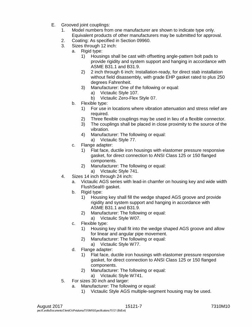
August 2017 15121-7 7310M10 pw://Carollo/Documents/Client/CA/Petaluma/7310M10/Specifications/15121 (BidSet)
E. Grooved joint couplings: 1. Model numbers from one manufacturer are shown to indicate type only.
Equivalent products of other manufacturers may be submitted for approval. 2. Coating: As specified in Section 09960. 3. Sizes through 12 inch:
a. Rigid type: 1) Housings shall be cast with offsetting angle-pattern bolt pads to
provide rigidity and system support and hanging in accordance with ASME B31.1 and B31.9.
2) 2 inch through 6 inch: Installation-ready, for direct stab installation without field disassembly, with grade EHP gasket rated to plus 250 degrees Fahrenheit.
3) Manufacturer: One of the following or equal: a) Victaulic Style 107. b) Victaulic Zero-Flex Style 07.
b. Flexible type: 1) For use in locations where vibration attenuation and stress relief are
required. 2) Three flexible couplings may be used in lieu of a flexible connector. 3) The couplings shall be placed in close proximity to the source of the
vibration. 4) Manufacturer: The following or equal:
a) Victaulic Style 77. c. Flange adapter:
1) Flat face, ductile iron housings with elastomer pressure responsive gasket, for direct connection to ANSI Class 125 or 150 flanged components.
2) Manufacturer: The following or equal: a) Victaulic Style 741.
4. Sizes 14 inch through 24 inch: a. Victaulic AGS series with lead-in chamfer on housing key and wide width
FlushSeal® gasket. b. Rigid type:
1) Housing key shall fill the wedge shaped AGS groove and provide rigidity and system support and hanging in accordance with ASME B31.1 and B31.9.
2) Manufacturer: The following or equal: a) Victaulic Style W07.
c. Flexible type: 1) Housing key shall fit into the wedge shaped AGS groove and allow
for linear and angular pipe movement. 2) Manufacturer: The following or equal:
a) Victaulic Style W77. d. Flange adapter:
1) Flat face, ductile iron housings with elastomer pressure responsive gasket, for direct connection to ANSI Class 125 or 150 flanged components.
2) Manufacturer: The following or equal: a) Victaulic Style W741.
5. For sizes 30 inch and larger: a. Manufacturer: The following or equal:
1) Victaulic Style AGS multiple-segment housing may be used.

August 2017 15121-8 7310M10 pw://Carollo/Documents/Client/CA/Petaluma/7310M10/Specifications/15121 (BidSet)
2.04 PIPE COUPLINGS FOR STAINLESS STEEL PIPING
A. Flexible couplings: 1. Manufacturers: One of the following or equal:
a. Dresser, Inc., Style 38.
B. Grooved joint couplings: 1. Manufacturers: One of the following or equal:
a. Victaulic Company. 2. Materials:
a. Housings: 1) Ductile iron in accordance with ASTM A536. 2) Stainless steel in accordance with ASTM A351.
b. Gasket: Elastomer in accordance with ASTM D2000. c. Bolts and nuts:
1) Electroplated steel in accordance with ASTM A449. 2) Stainless steel in accordance with ASTM F593.
3. Rigid type: a. Victaulic Style 89 and W89 (ductile iron housings). b. Victaulic Style 489 (stainless steel housings).
4. Flexible type: Victaulic Style 77S.
PART 3 EXECUTION
3.01 INSTALLATION
A. In underground and underwater installations, coat the exterior of coupling with a protective coating in accordance with manufacturer's instructions.
B. Joints and flexible connections shall be installed centered with no angular deflection unless otherwise indicated on the Drawings.
C. Flexible couplings and flange coupling adapters: Install with gap between pipe ends in accordance with the following table unless a greater gap is indicated on the Drawings. Maximum gap tolerance shall be within 1/8 inch. 1. Install flexible coupling with pipe gap located in middle of center sleeve. 2. Install flanged coupling adapter with end of plain end pipe in middle of flanged
coupling body. Center Ring Length Gap Dimension and Tolerance 4 inch through 6 inch 3/8 inch
7 inch 5/8 inch
10 inch and greater 7/8 inch
D. Provide harnesses (tie-downs) for flexible couplings unless otherwise indicated on the Drawings with a written note. 1. Design harnesses (tie-downs) for the test pressures as specified in the Piping
Schedule in Section 15052.

August 2017 15121-9 7310M10 pw://Carollo/Documents/Client/CA/Petaluma/7310M10/Specifications/15121 (BidSet)
E. Grooved joint couplings: 1. Grooved ends: Clean and free from indentations, projections, and roll marks in
the area from pipe end to groove. 2. Gaskets: Elastomer grade suitable for the intended service, and molded and
produced by the coupling manufacturer.
END OF SECTION

August 2017 15210-1 7310M10 pw://Carollo/Documents/Client/CA/Petaluma/7310M10/Specifications/15210 (BidSet)
SECTION 15210
CAST IRON SOIL PIPE: ASTM A74
PART 1 GENERAL
1.01 SUMMARY
A. Section includes: Cast iron soil piping and acid resistant cast iron soil piping.
B. Related sections: 1. Section 01330 - Submittal Procedures. 2. Section 09960 - High Performance Coatings. 3. Section 15052 - Common Work Results for General Process Piping. 4. Section 15956 - Piping Systems Testing.
1.02 REFERENCES
A. ASTM International (ASTM): 1. A74 - Standard Specification for Cast Iron Soil Pipe and Fittings. 2. A888 - Standard Specifications for Hubless Cast Iron Soil Pipe and Fittings for
Sanitary and Storm Drain, Waste, and Vent Pipe Applications. 3. C564 - Standard Specification for Rubber Gaskets for Cast Iron Soil Pipe and
Fittings.
1.03 SUBMITTALS
A. Submit as specified in Section 01330.
B. Product data: As specified in Section 15052.
PART 2 PRODUCTS
2.01 MATERIALS
A. Cast iron soil piping, underground: 1. Cast iron soil pipe underground: Bell-and-spigot service weight cast iron soil
pipe in accordance with ASTM A74. 2. Make joints by using positive double seal compression type gaskets in
accordance with ASTM C564. 3. Pipe and fittings shall be marked with the collective trademark of the Cast Iron
Soil Pipe Institute.
B. Cast iron soil piping, aboveground: 1. Piping: As specified for cast iron soil piping underground, or "No Hub" cast iron
soil pipe and fittings: a. Couplings for no hub cast iron soil piping: Consisting of a stainless steel
corrugated shield and clamp assembly over a molded 1-piece neoprene sealing sleeve, in accordance with ASTM A888.

August 2017 15210-2 7310M10 pw://Carollo/Documents/Client/CA/Petaluma/7310M10/Specifications/15210 (BidSet)
2. Threaded joints: American standard taper screw threads, cut clean and made up with Teflon tape or an acceptable paste thread compound applied to the male threads only.
3. Pipe and fittings shall be marked with the collective trademark of the Cast Iron Soil Pipe Institute.
2.02 FABRICATION
A. Lining and coating: 1. Line cast iron soil pipe and fittings inside and coat outside with bituminous
coating except as follows:
PART 3 EXECUTION
3.01 INSTALLATION
A. Cast iron soil piping: 1. Encase in concrete underground cast iron soil piping under structures.
a. Encase pipe as indicated on the Drawings. 2. Support aboveground horizontal cast iron soil piping at not more than 5 foot
spacing. 3. Aboveground vertical cast iron soil piping:
a. Install vertical piping in chases in the wall where the wall is plastered; where the wall is not plastered, vertical piping may be installed in chases in the wall or may be run exposed.
b. Support vertical pipes at the base and at each floor. 4. Fittings:
a. Make junctions with sanitary tees or with wyes, with brass screw plug cleanouts at accessible locations at changes in direction.
b. Make changes in pipe size with reducing fittings. c. Make changes in direction by use of 45 degree wyes, half wyes, long
sweep 1/4 bends, 1/5, 1/6, 1/8, or 1/16 bends, except that sanitary tees may be used on vertical stacks; short 1/4 bends or elbows 3 inches in size or larger may be used on soil or waste lines where the change in direction of flow is from horizontal to vertical, and on the discharge from water closets.
d. Cleanouts: Same size as the pipe, except that cleanout plugs larger than 4 inches will not be required.
B. Acid-resistant cast iron piping: 1. Where rope packing is used, caulk packing into half the depth of the hub.
a. Ram packing well in accordance with manufacturer's published instructions.
b. After ramming, fill the joints with lead and caulk in accordance with the manufacturer's published instructions.
c. Preheat hubs before pouring lead. 2. Do not use hemp packing and jute packing for joints of acid resistant piping.

August 2017 15210-3 7310M10 pw://Carollo/Documents/Client/CA/Petaluma/7310M10/Specifications/15210 (BidSet)
3.02 FIELD QUALITY CONTROL
A. Test as specified in Section 15052 and Section 15956.
END OF SECTION


August 2017 15211-1 7310M10 pw://Carollo/Documents/Client/CA/Petaluma/7310M10/Specifications/15211 (BidSet)
SECTION 15211
DUCTILE IRON PIPE: AWWA C151
PART 1 GENERAL
1.01 SUMMARY
A. Section includes: Ductile iron pipe, joints, fittings, gaskets, and pipe linings and coatings.
B. Related sections: 1. Section 01330 - Submittal Procedures. 2. Section 02318 - Trenching. 3. Section 09960 - High-Performance Coatings. 4. Section 13115 - Yard Piping Cathodic Protection. 5. Section 15052 - Common Work Results for General Process Piping. 6. Section 15057 - Fusion Bonded Epoxy Lining. 7. Section 15956 - Piping Systems Testing.
1.02 REFERENCES
A. American Society of Mechanical Engineers (ASME): 1. B16.1 - Gray Iron Pipe Flanges and Flanged Fittings: Classes 25, 125, and
250.
B. American Water Works Association (AWWA): 1. C104 - Standard for Cement-Mortar Lining for Ductile-Iron Pipe and Fittings. 2. C105 - Polyethylene Encasement for Ductile-Iron Pipe Systems. 3. C110 - Standard for Ductile-Iron and Gray-Iron Fittings. 4. C111 - Standard for Rubber-Gasket Joints for Ductile-Iron Pressure Pipe and
Fittings. 5. C115 - Flanged Ductile Iron Pipe with Ductile-Iron or Gray-Iron Threaded
Flanges. 6. C150 - Standard for Thickness Design of Ductile-Iron Pipe. 7. C151 - Standard for Ductile-Iron Pipe, Centrifugally Cast. 8. C600 - Installation of Ductile Iron Water Mains and Their Appurtenances. 9. C606 - Standard for Grooved and Shouldered Joints.
C. American Welding Society (AWS): 1. D11.2 - Guide for Welding Iron Castings.
D. ASTM International (ASTM): 1. A47 - Standard Specifications for Ferritic Malleable Iron Castings. 2. A183 - Standard Specifications for Carbon Steel Track Bolts and Nuts. 3. A536 - Standard Specifications for Ductile Iron Castings. 4. C283 - Standard Test Methods for Resistance of Porcelain Enameled Utensils
to Boiling Acid. 5. D792 - Standard Test Methods for Density and Specific Gravity (Relative
Density) of Plastics by Displacement.

August 2017 15211-2 7310M10 pw://Carollo/Documents/Client/CA/Petaluma/7310M10/Specifications/15211 (BidSet)
E. Ductile Iron Pipe Research Association (DIPRA): 1. Thrust Restraint Design Manual.
F. NACE International (NACE): 1. SP0188 - Discontinuity (Holiday) Testing of New Protective Coatings on
Conductive Substrates.
G. National Association of Pipe Fabricators, Inc. (NAPF): 1. 500-03 - Surface Preparation Standard for Ductile Iron Pipe and Fittings in
Exposed Locations Receiving Special External Coatings and/or Special Internal Linings.
H. Society for Protective Coatings (SSPC): 1. PA-2 - Measurement of Dry Coating Thickness With Magnetic Gages.
1.03 SYSTEM DESCRIPTION
A. Thrust restraint system design: 1. Design restrained joint thrust restraint system. 2. Determine the length of pipe that must be restrained on each side of the focus
of a thrust load in accordance with the procedures and criteria established by the DIPRA Thrust Restraint Design Manual as specified in Piping Schedule in Section 15052 and the following additional criteria: a. Design pressure: Test pressure. b. Laying condition: Type 3in accordance with AWWA C150. c. Soil designation: Silt 1as defined by DIPRA. d. Unit friction resistance: Based upon polyethylene encasement of pipe. e. Safety factor: 1.5 (for thrust restraint calculations only).
1.04 SUBMITTALS
A. Submit as specified in Section 01330.
B. Product data: As specified in Section 15052.
C. Shop drawings: 1. Detailed layout drawings showing alignment of pipes, location of valves,
fittings, and appurtenances, types of joints, and connections to pipelines or structures.
2. Thrust restraint systems layouts. 3. Photographs, drawings, and descriptions of fittings, gaskets, couplings,
grooving of pipe and fittings, pipe linings, and coatings.
D. Calculations: 1. Calculations for thrust restraint system design.
E. Provide manufacturer’s test reports: 1. glass lining certifying successful performance of holiday detection tests.
a. This documentation shall identify each piece by mark designation, and show the actual test results during the final inspection by the manufacturer prior to shipment.
b. Acceptance criteria for glass lining shall be as specified under Field Quality Control.
August 2017 15211-3 7310M10 pw://Carollo/Documents/Client/CA/Petaluma/7310M10/Specifications/15211 (BidSet)
2. On glass-lined pipe certifying compliance with specified material requirements for glass-lining.
3. Include Coating Manufacturer’s Technical Representative’s reports.
1.05 QUALITY ASSURANCE
A. Pre-installation meeting: 1. Arrange for Coating Manufacturer’s Technical Representative to attend
preconstruction conferences, and to make periodic visits to factory or shop to inspect surface preparation of pipe, fittings, and accessories; and to inspect application of linings to interior and coatings to exterior of pipe, fittings, and accessories.
1.06 DELIVERY, STORAGE, AND HANDLING
A. Block piping and associated fittings for shipment to prevent damage to coatings and linings.
B. Carefully handle piping and associated fittings during loading, unloading, and installation: 1. Do not drop piping material from cars or trucks. 2. Lower piping by mechanical means. 3. Do not drop or pound pipe to fit grade.
C. Glass lined pipe and fittings must be handled only from the outside: 1. No forks, chains, straps, hooks, or other lifting device shall be placed inside
the pipe or fittings for lifting, positioning, or laying.
D. Protect gaskets and polyethylene encasement from long-term exposure to sunlight.
E. Store piping, fittings, and other accessories such that they do not accumulate and hold rainwater, dirt, and debris.
PART 2 PRODUCTS
2.01 MANUFACTURED UNITS
A. Ductile iron piping: 1. Manufacturers meeting qualifications as specified in this Section. 2. Typical type:
a. In accordance with AWWA C150 and AWWA C151. b. Pressure class or special thickness class as indicated in the Piping
Schedule provided in Section 15052 [indicated on the Drawings]. c. Manufactured from greater than 90 percent recycled material.
3. Type with screw-on flanges: a. In accordance with AWWA C115 with minimum special thickness
Class 53 wall thickness as required for screw-on flanges. b. Special thickness class as indicated in the Piping Schedule as specified in
Section 15052. c. Manufactured from greater than 90 percent recycled material.

August 2017 15211-4 7310M10 pw://Carollo/Documents/Client/CA/Petaluma/7310M10/Specifications/15211 (BidSet)
4. Type with grooved couplings: a. Special thickness class as indicated in the Piping Schedule as specified in
Section 15052. b. Manufactured from greater than 90 percent recycled material.
B. Joints: 1. Flanged joints:
a. Screw-on flanges: Comply with the diameter, thickness, drilling, and other characteristics in accordance with ASME B16.1. In addition, comply with the following requirements: 1) Ductile iron. 2) Long hub, threaded, and specially designed for ductile iron pipe. 3) After attaching to pipe, machine flange face to make pipe end and
flange even and perpendicular to the axis of the pipe. b. Bolt holes on flanges: 2-holed and aligned at both ends of pipe. c. Cap screw or stud bolt holes: Tapped. d. Bolts and nuts: As specified in Section 15052. e. Gaskets: Standard styrene butadiene copolymer (SBR) unless specified
otherwise in Section 15052. 2. Grooved joints: In accordance with AWWA C606, as complemented and
modified below, radius-cut type, with following components: a. Couplings: Rigid type, cast from ductile iron in accordance with
ASTM A536, Grade 65-45-12, or malleable iron in accordance with ASTM A47, Grade 32510.
b. Bolts and nuts: In accordance with ASTM A183, Grade 2. c. Gaskets: Capable of being applied on surface of piping with cavities to
provide for an improved seal with the internal piping pressure. Material to be used for following services: 1) For liquid service: NBR. 2) For air service: Fluoroelastomer. 3) For hot water service: EPDM.
d. Fittings: In accordance with AWWA C606, rigid radius-cut groove: 1) Center-to-center dimensions: In accordance with AWWA C110. 2) Wall thickness and other characteristics: In accordance with
AWWA C606. e. Flanged unit connections: Flanged to grooved joint adapters or a long
enough spool with one end flanged and the other end grooved to prevent interference with the operation of adjacent valves, pumps, or other items.
3. Mechanical joints: In accordance with AWWA C111. 4. Push-on rubber gasket joints: In accordance with AWWA C111. 5. Integrally restrained mechanical joints:
a. Application: 1) Where designation Mech Rest. 2) Mechanical joint is specified in the Piping Schedule provided in
Section 15052 or indicated on the Drawings], supply a restrained mechanical joint piping system, which includes restrained mechanical joints where necessary based upon thrust calculations.
3) Standard mechanical joints as specified above can be used where thrust calculations demonstrate restraint is not required.
b. Design: 1) Integral retainer weldment type or lugged type joint with Type 304
stainless steel rods and nuts.

August 2017 15211-5 7310M10 pw://Carollo/Documents/Client/CA/Petaluma/7310M10/Specifications/15211 (BidSet)
2) Restrained mechanical joints of the configuration which utilizes a gripping or friction force for restraint will not be acceptable.
c. Manufacturers: Where restrained mechanical joints are required, use one of the following or equal: 1) American Cast Iron Pipe Company, MJ Coupled Joint. 2) Pacific States Cast Iron Pipe Company, Lock Mechanical Joint. 3) U.S. Pipe, Bolt-Lok. 4) U.S. Pipe, Mech-Lok.
6. Mechanical wedge action joint restraints: a. Manufacturers: One of the following or equal:
1) EBAA Iron, Inc., Megalug Series 1100. 2) Star Pipe Products, Split Stargrip Series 3000. 3) Sigma Corporation, One-Lok Model SLDE.
b. Materials: 1) Gland body: Ductile iron in accordance with ASTM A536. 2) Wedges and wedge actuating components: Ductile iron in
accordance with ASTM A536. a) Wedges shall be heat treated to a minimum of 370 BHN.
3) Actuating bolts and nuts: Ductile iron in accordance with ASTM A536. a) Provide torque-limiting twist off components to ensure proper
installation. c. Coatings:
1) Provide manufacturer applied coating system. 2) Manufacturers: One of the following or equal:
a) EBAA Iron Inc., Mega-Bond. b) Star Pipe Products, Star-Bond. c) Sigma Corporation, CorrsafeTM Electro-deposition coating.
d. Working pressure: 1) Shall include a minimum safety factor of 2:1. 2) For sizes 3- through 16-inch: 350 pounds per square inch.
e. Restraint shall consist of multiple gripping wedges incorporated into a follower gland meeting the requirements of AWWA C111.
f. Restraint shall allow post assembly angular deflection that is a minimum of 50 percent of the angular deflection allowed by the mechanical joint.
g. Restraint must be in accordance with applicable requirements of AWWA C110 and AWWA C111 for mechanical joints.
7. Integrally restrained push-on joints: a. Application:
1) Where designation restrained push-on is specified in the Piping Schedule provided in Section 15052, supply a restrained push-on joint piping system, which includes restrained push-on joints where necessary based upon thrust calculations.
2) Standard push-on rubber gasket joints as specified above can be used where thrust calculations demonstrate restraint is not required.
b. Design: 1) Restrained push-on joints of the configuration which utilizes a
gripping or friction force for restraint will not be acceptable. 2) Suitable for the following working pressures:
a) For 4- through 24-inch pipe: 350 pounds per square inch gauge. b) For 30- through 54-inch pipe: 250 pounds per square inch
gauge.

August 2017 15211-6 7310M10 pw://Carollo/Documents/Client/CA/Petaluma/7310M10/Specifications/15211 (BidSet)
c. Manufacturers: One of the following or equal: 1) U.S. Pipe, TR Flex. 2) McWane Ductile, TR Flex. 3) American Cast Iron Pipe Company, Flex Ring or Lok-Ring.
d. Limit buried joints to half the manufacturer’s published allowable angular joint deflection for purposes of pipeline alignment and elimination of fittings.
C. Fittings: 1. Ductile iron in accordance with AWWA C110. 2. Joint type: Same as that of the associated piping as specified in
Section 15052. 3. Plain end-to-flanged joint connectors using setscrews are not acceptable.
D. Pipe and fitting linings: 1. Cement-mortar lining:
a. In accordance with AWWA C104, apply cement-mortar on clean bare metal surfaces. Extend to faces of flanges, ends of spigots, and shoulders of hubs.
b. Minimum lining thickness: Standard in accordance with AWWA C104. c. Type of cement: Type II.
2. Elastomeric polyurethane (100 percent solids) lining: a. As specified in Section 09960.
3. Ceramic epoxy lining: a. Manufacturers: One of the following or equal:
1) PROTECTO 401. 2) SP-2000W.
b. Material: Amine cured Novolac epoxy containing at least 20 percent by volume of ceramic quartz pigment.
c. Minimum dry film thickness (DFT): 40 mills. d. Application:
1) The lining shall only be applied by a manufacturer-authorized representative with no less than 5 years of experience in applying the specified material.
2) The application of the lining shall be preformed in accordance with manufacturer’s published specifications.
3) Pipe and fittings shall be delivered to application facility with no interior lining.
4) Interior of pipe shall be abrasive blasted per manufacturer’s specifications.
e. Coverage: 1) Gasket and spigot ends-on joints: Provide 6 mils minimum and
10 mils maximum coverage using joint compound as specified by the manufacturer for the gasket area and spigot ends.
2) Mechanical joints: Extend lining from spigot end to edge of gauging ring.
3) Number of coats: As recommended by the lining manufacturer. f. Source quality control:
1) Test pipe and fitting lining with a magnetic film thickness gauge. Perform testing in accordance with the method outlined in SSPC PA-2 Film Thickness Rating.

August 2017 15211-7 7310M10 pw://Carollo/Documents/Client/CA/Petaluma/7310M10/Specifications/15211 (BidSet)
2) Test lining integrity of pipes using a holiday detection testing instrument set at the voltage as specified by the coating manufacturer: a) Repair all holidays with joint compound in accordance with the
recommendations of the coating manufacturer, and re-test. 3) Discard piping or reline piping when pinholes or discontinuities are
found. 4. Glass lining:
a. Manufacturers: One of the following or equal: 1) Water Works Manufacturing, Ferrock MEH-32 Lining. 2) Vitco Corporation, SG-14 Lining.
b. Material: Special glasses and inorganic materials suited for lining of sewage, sludge, and scum piping with the following characteristics: 1) Thickness: 0.008 to 0.012 inch. 2) Hardness: 5 to 6 on the Mohs Scale. 3) Density: 2.5 to 3.0 grams per cubic centimeter, measured in
accordance with ASTM D792. 4) Thermal shock resistance: Capable of withstanding 350 degrees
Fahrenheit change from 430 degrees Fahrenheit to 80 degrees Fahrenheit without crazing, blistering, or spalling.
5) Gloss retention: Capable of retaining gloss after immersion in an 8 percent sulfuric acid solution at 148 degrees Fahrenheit for 10 minutes.
6) Weight loss: Maximum 3 milligrams per square inch when tested in accordance with ASTM C283.
c. Fabrication: 1) Use piping that is suitable for glass lining with minimum Class 53 wall
thickness after application of glass lining. 2) Machine interior of pipe. Bore or grit blast in accordance with
NAPF 500-03 prior to application of glass lining. 3) Screw factory assembled flanges on pipe, align boltholes, and flange
faces, unless otherwise specified. 4) Apply lining to surfaces free of chemicals. 5) Place piping in furnaces specially designed for heating piping until
glass melts and fuses with an integral molecular bond to the base metal.
E. Coatings: 1. Asphalt varnish: Factory applied. 2. Primer:
a. Factory applied for field coating. b. Compatible with materials as specified in Section 09960.
2.02 POLYETHYLENE ENCASEMENT
A. General: 1. Polyethylene encasement shall be supplied by the pipe manufacturer.
B. Materials: Supply one of the following polyethylene encasements: 1. 2 layers of linear low-density polyethylene (LLDPE) film, minimum thickness of
8 mils in accordance with AWWA C105; or 2. Single layer of high-density, cross-laminated polyethylene (HDCLPE) film,
minimum thickness of 4 mils in accordance with AWWA C105.
August 2017 15211-8 7310M10 pw://Carollo/Documents/Client/CA/Petaluma/7310M10/Specifications/15211 (BidSet)
3. Single layer of V-Bio® enhanced polyethylene encasement (3 layers of co-extruded LLDPE film with anti-microbial additive and volatile corrosion inhibitor infused on the inside surface), meeting all requirements of AWWA C105.
PART 3 EXECUTION
3.01 INSTALLATION
A. General: 1. Install ductile iron piping in accordance with AWWA C600, modified as
specified in Section 15052. 2. For underground piping, the trenching, backfill, and compaction: As specified
in Section 02318.
B. Polyethylene encasement: 1. Wrap all buried ductile iron pipe and fittings in 2 layers of loose low density
polyethylene wrap or a single layer of high-density polyethylene wrap in accordance with AWWA C105.
2. Polyethylene encasement shall be continuous and terminated neatly at connections to below grade equipment or structures.
3. At wall penetrations, extend encasement to the wall and neatly terminate. 4. At slab penetrations, extend encasement to 2 inches below the top of slab and
neatly terminate. 5. When rising vertically in unimproved areas, extend encasement 6 inches
above existing grade and neatly terminate. 6. Repair tears and make joints with 2 layers of plastic tape. 7. All work shall be inspected prior to backfilling of pipe and associated items.
C. Joints: 1. Install types of joints as specified in the piping schedule provided in
Section 15052. 2. Mechanical joints are not acceptable in above ground applications. 3. Field closure for restrained push-on pipe:
a. Locate field closures in areas where thrust calculations demonstrate restraint is not required.
4. Grooved joints: a. Install piping with grooved joints where specified in the piping schedule as
specified in Section 15052 or indicated on the Drawings. b. Assemble grooved joints in accordance with manufacturer's published
instructions. c. Support grooved-end pipe in accordance with manufacturer's published
instructions. 1) Install at least 1 support between consecutive couplings.
D. Tapping ductile iron pipe: 1. Direct tapping of ductile iron pipe may be performed but is limited to the
following conditions: a. Maximum allowable tap diameter by pipe diameter and pressure class:

August 2017 15211-9 7310M10 pw://Carollo/Documents/Client/CA/Petaluma/7310M10/Specifications/15211 (BidSet)
Pipe Size (inches)
Pressure Class 150 200 250 300 350
Maximum Allowable Direct Tap Size (inches)
3 - - - - 3/4 4 - - - - 3/4 6 - - - - 1 8 - - - - 1
10 - - - - 1 12 - - - - 1-1/4 14 - - 1-1/4 1-1/2 1-1/2 16 - - 1-1/2 2 2 18 - - 2 2 2 20 - - 2 2 2 24 - 2 2 2 2
b. The maximum allowable tap diameter for pipelines greater than 24 inches is 2 inches.
c. Two layers of 3-mil thread sealant are required to minimize the torque required to effect a watertight connection.
2. Direct tapping of glass lined ductile iron pipe may be performed only when approved in writing by the Engineer. Direct tapping of glass lined pipe shall be performed in accordance with the above conditions for tapping ductile iron pipe in addition to the following conditions: a. Drilling and tapping shall be performed using a hole saw.
1) Use of a large drill bit is not acceptable. b. As the hole saw approaches the glass lining, lessen the inward pressure
to avoid excess chipping or cracking of the lining. c. Minor chipping or spalling of the glass lining shall be repaired using an
epoxy resin “glass repair kit” provided by the fabricator. 1) Manufacturers: One of the following or equal:
a) Devoe - Devran 224 HS. b) Sherwin-Williams Co. – Sher-Tile High Solids Epoxy.
2) Repair kit use is only allowed for areas of damage less than 1/2 inch in diameter. a) Larger areas of damage will require replacement.
3) Surface shall be prepared and repair kit shall be applied in accordance with manufacturer and/or fabricator’s instructions.
3.02 FIELD QUALITY CONTROL
A. Testing ductile iron piping: 1. Test as specified in Section 15052 and Section 15956. 2. Do not test sections longer than 1/2 mile in total pipe length.

August 2017 15211-10 7310M10 pw://Carollo/Documents/Client/CA/Petaluma/7310M10/Specifications/15211 (BidSet)
B. Repair damaged cement mortar lining to match quality, thickness, and bonding of original lining in accordance with AWWA C104. 1. When lining cannot be repaired or repairs are defective, replace defective
piping with undamaged piping.
C. Verify that interior surfaces of glass lined pipe and fittings have continuous coverage: 1. Verify with low voltage wet sponge holiday detector in accordance with
NACE SP0188. 2. Discard glass lined ductile iron piping and fittings with voids or casting
anomalies. that exceed the maximum non-visible pinholes allowances below:
Diameter Maximum Pinholes
Fittings Pipe (per 20-foot length of pipe) 4- to 8-inch 3-5 10-12
10- to 18-inch 5-8 18-20 20-inch and Larger 8-10 25-28
3. Discard lined piping and fittings found to have pinholes, crazing, or fish scales, which expose the metal substrate.
END OF SECTION

August 2017 15234-1 7310M10 pw://Carollo/Documents/Client/CA/Petaluma/7310M10/Specifications/15234 (BidSet)
SECTION 15234
POLYETHYLENE (PE) PIPE: ASTM D2513
PART 1 GENERAL
1.01 SUMMARY
A. Section includes: ASTM D2513 polyethylene piping and fittings.
B. Related sections: 1. Section 01330 - Submittal Procedures. 2. Section 15052 - Common Work Results for General Piping. 3. Section 15076 - Pipe Marking. 4. Section 15956 - Piping Systems Testing.
1.02 REFERENCES
A. ASTM International (ASTM): 1. D1248 - Standard Specification for Polyethylene Plastics Extrusion Materials
for Wire and Cable. 2. D2513 - Standard Specification for Polyethylene (PE) Gas Pressure Pipe,
Tubing and Fittings. 3. D2683 - Standard Specification for Socket-Type Polyethylene Fittings for
Outside Diameter-Controlled Polyethylene Pipe and Tubing. 4. D3261 - Standard Specification for Butt Heat Fusion Polyethylene (PE) Plastic
Fittings for Polyethylene (PE) Plastic Pipe and Tubing. 5. F645 - Standard Guide for Selection, Design and Installation of Thermoplastic
Water-Pressure Piping Systems.
1.03 ABBREVIATIONS
A. NPS: Nominal pipe size followed by the size designation.
B. PE: Polyethylene.
C. SDR: Standard dimension ratio; the outside diameter divided by the pipe wall thickness.
1.04 SUBMITTALS
A. Submit as specified in Section 01330.
B. Product data: As specified in Section 15052.
C. Shop drawings.
D. Calculations.

August 2017 15234-2 7310M10 pw://Carollo/Documents/Client/CA/Petaluma/7310M10/Specifications/15234 (BidSet)
1.05 DELIVERY, STORAGE, AND HANDLING
A. Protect from sunlight, scoring, and distortion.
B. Do not allow surface temperatures to exceed 120 degrees Fahrenheit.
C. Store and handle as recommended by manufacturer in published instructions.
PART 2 PRODUCTS
2.01 MATERIALS
A. Extruding and molding material: 1. Virgin material containing no scrap, regrind, or rework material except where
permitted in the referenced standards. 2. Fittings shall be same material as the pipe and of equal or greater pressure
rating.
B. Manufacturers: One of the following or equal: 1. DuPont. 2. Amsted Industries, Inc., Plexco.
C. Manufactured in accordance with ASTM D2513 using a compound in accordance with ASTM D1248, PE 2306/2406:
D. SDR: Maximum of 11.
E. Fittings: In accordance with ASTM D2683 for socked fusion joints, and ASTM D3261 for butt fusion joints.
2.02 SOURCE QUALITY CONTROL
A. Mark pipe and fittings in accordance with ASTM D2513.
PART 3 EXECUTION
3.01 INSTALLATION
A. General: 1. Install piping in accordance with ASTM F645, or manufacturer's published
instructions for installation of piping, as applicable to the particular type of piping.
2. For open cut installations, install underground warning tape as specified in Section 15076.
3. Install pipe with tracer wire as specified in Section 15076. 4. Socket fuse joints for piping equal or less than NPS 2. 5. Butt fuse joints for piping larger than NPS 2.
August 2017 15234-3 7310M10 pw://Carollo/Documents/Client/CA/Petaluma/7310M10/Specifications/15234 (BidSet)
3.02 FIELD QUALITY CONTROL
A. Test pipe as specified in Section 15052 and Section 15956.
END OF SECTION


August 2017 15249-1 7310M10 pw://Carollo/Documents/Client/CA/Petaluma/7310M10/Specifications/15249 (BidSet)
SECTION 15249
POLYVINYL CHLORIDE (PVC) PIPE: SCHEDULE TYPE
PART 1 GENERAL
1.01 SUMMARY
A. Section includes: Schedule type PVC pipe and fittings.
B. Related sections: 1. Section 01330 - Submittal Procedures. 2. Section 15052 - Common Work Results for General Piping. 3. Section 15956 - Piping Systems Testing.
1.02 REFERENCES
A. ASTM International (ASTM): 1. D1784 - Standard Specification for Rigid Poly(Vinyl Chloride) (PVC)
Compounds and Chlorinated Poly(Vinyl Chloride) (CPVC) Compounds. 2. D1785 - Standard Specification for Poly(Vinyl Chloride) (PVC) Plastic Pipe,
Schedules 40, 80 and 120. 3. D2467 - Standard Specification for Poly(Vinyl Chloride) (PVC) Plastic Pipe
Fittings, Schedule 80. 4. D2564 - Standard Specification for Solvent Cements for Poly(Vinyl Chloride)
(PVC) Plastic Piping Systems. 5. D2855 - Standard Practice for Making Solvent-Cemented Joints with Poly
(Vinyl Chloride)(PVC) Pipe and Fittings. 6. F645 - Standard Guide for Selection, Design and Installation of Thermoplastic
Water-Pressure Piping Systems.
B. NSF International (NSF): 1. 61 - Drinking Water System Components – Health Effects.
1.03 SUBMITTALS
A. Submit as specified in Section 01330.
B. Product data: As specified in Section 15052.
1.04 DELIVERY, STORAGE, AND HANDLING
A. Protect from sunlight, scoring, and distortion.
B. Do not allow surface temperatures to exceed 120 degrees Fahrenheit.
C. Store and handle as recommended by manufacturer in published instructions.

August 2017 15249-2 7310M10 pw://Carollo/Documents/Client/CA/Petaluma/7310M10/Specifications/15249 (BidSet)
PART 2 PRODUCTS
2.01 MATERIALS
A. Extruding and molding material: Virgin material containing no scrap, regrind, or rework material except where permitted in the referenced standards. 1. Pipe: Designation PVC 1120 in accordance with ASTM D1785 and
appendices: a. Extruded from Type I, Grade 1, Class 12454-B material in accordance
with ASTM D1784. b. Schedule 80 unless otherwise indicated on the Drawings or specified in
the Piping Schedule in Section 15052. 2. Fittings: In accordance with ASTM D2467.
a. Same material as the pipe and of equal or greater pressure rating. b. Supplied by pipe manufacturer. c. Unions 2-1/2 inches and smaller:
1) Use socket end screwed unions. d. Unions 3 inches and larger:
1) Use socket flanges with 1/8-inch full-face soft neoprene gasket. 3. Solvent cement:
a. In accordance with ASTM D2564. b. Manufacturers: The following or equal:
1) IPS Corporation. c. Certified by the manufacturer for the service of the pipe. d. In potable water applications: Provide solvent cement listed by NSF for
potable water applications. e. Primer: As recommended by the solvent cement manufacturer.
2.02 SOURCE QUALITY CONTROL
A. Meets or exceeds all quality assurance test requirements stated in ASTM D1785.
PART 3 EXECUTION
3.01 INSTALLATION
A. Install piping in accordance with ASTM F645, or manufacturer's published instructions for installation of piping, as applicable.
B. Provide molded transition fittings for transitions from plastic to metal pipe. 1. Do not thread pipe.
C. Locate unions where indicated on the Drawings, and elsewhere where required for adequate access and assembly of the piping system.
D. Provide serrated nipples for transition from pipe to rubber hose.
E. Solvent weld joints in accordance with ASTM D2855.

August 2017 15249-3 7310M10 pw://Carollo/Documents/Client/CA/Petaluma/7310M10/Specifications/15249 (BidSet)
3.02 FIELD QUALITY CONTROL
A. Test pipe as specified in Section 15052 and Section 15956.
END OF SECTION


August 2017 15281-1 7310M10 pw://Carollo/Documents/Client/CA/Petaluma/7310M10/MF95/15281 (BidSet)
SECTION 15281
COPPER WATER TUBE: SEAMLESS, ASTM B88
PART 1 GENERAL
1.01 SUMMARY
A. Section includes: Copper water tube-seamless, ASTM B88.
B. Related sections: 1. Section 01330 - Submittal Procedures. 2. Section 15052 - Common Work Results for General Piping. 3. Section 15061 - Pipe Supports. 4. Section 15062 - Preformed Channel Pipe Support System.
1.02 REFERENCES
A. ASTM International (ASTM): 1. B32 - Standard Specification for Solder Metal. 2. B88 - Standard Specification for Seamless Copper Water Tube. 3. B813 - Standard Specification for Liquid and Paste Fluxes for Soldering of
Copper and Copper Alloy Tube. 4. B828 - Standard Practice for Making Capillary Joints by Soldering of Copper
and Copper Alloy Tube and Fitting.
B. International Association of Plumbing and Mechanical Officials (IAPMO): 1. IS 3 - Installation Standard for Copper Plumbing Tube, Pipe and Fittings.
1.03 SUBMITTALS
A. Submit as specified in Section 01330.
B. Product data: As specified in Section 15052.
PART 2 PRODUCTS
2.01 MATERIALS
A. Seamless copper water tube: 1. Type: ASTM B88:
a. Exposed copper piping or tubing: Type L hard-drawn, rigid. b. Copper tubing buried in the ground or in plastic conduit: Type K
soft-annealed. 2. Fittings: Manufacturers: Solder type forged, or wrought copper. One of the
following or equal: a. Hoke, Gyrolok. b. Crawford Fitting Company, Swagelok. c. Parker.
3. Solder: ASTM B32, Alloy Grade Sb5.
August 2017 15281-2 7310M10 pw://Carollo/Documents/Client/CA/Petaluma/7310M10/MF95/15281 (BidSet)
4. Flux: ASTM B813. 5. Dielectric insulating unions or fittings: Manufacturers: One of the following or
equal: a. Mueller Company. b. Watts Series 3001A.
6. Special thread to tube adapters: Manufacturers: One of the following or equal: a. Crawford Fitting Company, Swagelok. b. Hoke, Gyrolok. c. Parker.
PART 3 EXECUTION
3.01 INSTALLATION
A. General: 1. Support copper piping and tubing as specified in Sections 15061 and 15062. 2. Clean copper lines with high-pressure air after first disconnecting piping at
instruments, filters, pressure reducers, valve operators, and other special devices.
3. Install copper pipe in accordance with IAPMO IS 3.
B. Installation of copper piping: 1. Connect copper pipe connected to ferrous pipe or valves, or other non-copper
items, by means of dielectric insulating unions or fittings. 2. Where connections are made to meters or other devices having iron pipe size
threaded fittings, provide special thread to tube adapters.
C. Installation of copper tubing: 1. Install copper tubing in accordance with ASTM B828 and IAPMO IS 3. 2. Install copper tubing in straight runs, supported at intervals close enough to
avoid sagging. 3. Make cuts square with a tubing cutter or with a 32-tooth hacksaw.
a. Provide a sizing tool to correct distortions. 4. Ream the inside of the tubing and remove burrs from the outside, holding the
end of the tubing downward and preventing chips and fillings from entering the tubing.
5. Perform flaring with a flare block and yoke type screw feed flaring tool: a. After removing the tubing from the flare block, inspect both surfaces of the
flare for splits, cracks, or other imperfections. b. Where there are imperfections, cut off the imperfect flare, and prepare a
new flare.
3.02 FIELD QUALITY CONTROL
A. Testing: Test copper lines in the same manner as the piping system to which they connect.
END OF SECTION

August 2017 15814-1 7310M10 pw://Carollo/Documents/Client/CA/Petaluma/7310M10/MF95/15814 (BidSet)
SECTION 15814
FIBERGLASS REINFORCED PLASTIC DUCTS
PART 1 GENERAL
1.01 SUMMARY
A. Section includes: Fiberglass reinforced plastic ductwork system, consisting of ducting and including fasteners, field joints, expansion joints, and supports.
B. Related sections: 1. Section 06608 - Fiberglass Reinforced Plastic.
1.02 REFERENCES
A. American Society of Mechanical Engineers (ASME): 1. B16.5 - Pipe Flanges and Flanged Fittings.
B. ASTM International (ASTM): 1. C582 - Standard Specification for Contact-Molded Reinforced Thermosetting
Plastic (RTP) Laminates for Corrosion-Resistant Equipment. 2. D792 - Standard Test Methods for Density and Specific Gravity (Relative
Density) of Plastics by Displacement. 3. D2105 - Standard Test Method for Longitudinal Tensile Properties of
Fiberglass (Glass-Fiber-Reinforced Thermosetting-Resin) Pipe and Tube. 4. D2344 - Standard Test Method for Short-Beam Strength of Polymer Matrix
Composite Materials and Their Laminates. 5. D2412 - Standard Test Method for Determination of External Loading
Characteristics of Plastic Pipe by Parallel-Plate Loading.
C. National Bureau of Standards Voluntary Product Standards (PS): 1. 15-69 - Custom Contact-Molded Reinforced-Polyester Chemical-Resistant
Process Equipment.
D. Sheet Metal and Air Conditioning Contractors' National Association (SMACNA).
1.03 DESIGN CRITERIA
A. Ducting under pressure conditions: 10.0 inches water column.
B. Ducting under vacuum conditions: 6.0 inches water column.
C. Support spacing: As needed to comply with wall thicknesses calculations but not greater than the following: 1. Contact-molded ductwork: Not greater than 5 foot centers. 2. Filament-wound ducts: In accordance with SMACNA standards below:
Duct Inside Diameter (Inches) Maximum Span (Feet)
3 to 19 10

August 2017 15814-2 7310M10 pw://Carollo/Documents/Client/CA/Petaluma/7310M10/MF95/15814 (BidSet)
Duct Inside Diameter (Inches) Maximum Span (Feet)
20 to 29 15
30 to 35 20
D. Minimum flooding: Design ductwork for water accumulation as follows: 1. Rectangular ductwork: 1 inch deep across bottom of duct. 2. Round ductwork: 2 inches deep across bottom of duct.
E. Physical and mechanical properties: Duct shall meet the following standards for physical and mechanical properties:
Pipe Property Standard
Design Properties
Hoop (PSI) Axial (PSI)
Ultimate Flexural Stress ASTM D2412
50,000 18,000
Flexural Modulus 3.05 X 10⁶ 1.0 X 10⁶
Ultimate Tensile Stress ASTM D2105
52,000 7,485
Tensile Modulus 1.5 X 10⁶ 1.56 X 10⁶
Ultimate Shear Strength Approximate Typical Values (PSI)
Interlaminar ASTM D2344
2130-2730
Cross 15,000
Density ASTM D792 0.065-0.072 lb./In3
F. Design tensile stress: 1. Round ducting: The maximum allowable design tensile stress shall be the
ultimate tensile stress divided by 5. 2. Rectangular ducting: The maximum allowable design tensile stress shall be
the ultimate tensile stress divided by 10.
1.04 SUBMITTALS
A. Product data: Composition of materials, configuration of external stiffeners, and flexible connections.
B. Shop drawings: 1. Drawings showing ductwork layout, dimensions, joint types, and support
locations. 2. Locations of external stiffeners and expansion joints. 3. Fabrication details. 4. Support locations, types, and details.
C. Calculations: 1. Wall thickness calculations based upon design criteria.

August 2017 15814-3 7310M10 pw://Carollo/Documents/Client/CA/Petaluma/7310M10/MF95/15814 (BidSet)
2. Stresses and reaction loads at supports.
D. Manufacturer's Installation Instructions.
1.05 QUALITY ASSURANCE
A. Qualification of ducting manufacturer: Manufacturer with experienced personnel, physical facilities, and management capacity sufficient to produce custom-made, corrosion resistant fiberglass reinforced plastic products of quality and size specified with a minimum 5 years satisfactory performance record.
B. Submit test results as specified in Section 06608 verifying that ductwork meets standards specified.
PART 2 PRODUCTS
2.01 MANUFACTURERS
A. Fiberglass reinforced plastic ductwork: One of the following or equal: 1. Bondstrand. 2. Fibercast. 3. Spunstrand. 4. Belco Manufacturing.
2.02 DUCTWORK MATERIALS
A. As specified in applicable portions of Section 06608.
B. Minimum corrosion liner: 1. Interior surfacing "C" or Nexus veil as specified for the service environment. 2. Exterior surfacing: “C” or “A” veil. 3. Remainder 1-1/2 ounce per square foot mat to total minimum thickness of
0.096 inches on surface exposed to the service environment. 4. Duct shall be resistant to the following in accordance with ASTM C 582:
Sulfuric Acid 75 percent At 100 degrees Fahrenheit
Nitric Acid 20 percent At 100 degrees Fahrenheit
Sodium Hydroxide 50 percent At 100 degrees Fahrenheit
Hydrofluoric Acid 20 percent At 100 degrees Fahrenheit
C. Ultra violet stabilizer: Add to the exterior surface resin coat of fabrications intended for outside service, in the type and amount recommended by the resin manufacturer.
D. Resin: Fire retardant premium vinyl ester as follows unless otherwise recommended by the resin manufacturer for the service environment: 1. Resin for structural layers: Resin with sufficient antimony trioxide or pentoxide
for Class I fire rating.

August 2017 15814-4 7310M10 pw://Carollo/Documents/Client/CA/Petaluma/7310M10/MF95/15814 (BidSet)
2. Manufacturers: One of the following or equal: a. Ashland, Hetron 992FR. b. Reichhold Dion, VER 9300FR.
E. Color: Add pigment to the exterior surface resin coat such that the color of the duct will be similar to paint used for equipment, except that ducting for air conditioning systems which are concealed above suspended ceilings need not be pigmented. Color selected by Owner.
F. Provide fasteners, field joints, expansion joints, and supports required for complete installation of a duct system.
G. Flanges: 1. All flanges shall be hand laid up to the thickness specified in accordance with
ASME B 16.5. Pipe Diameter,
Inches Minimum Flange Thickness,
Inches
Less Than 12 3/4
12-23 1
24-41 1-3/8
42-60 2
2.03 DUCTWORK FABRICATION
A. Hand lay-up or filament wound construction as specified in Section 06608. Provide wall thickness necessary to comply with design criteria but not less than the following minimum thicknesses:
Duct Size Round Ducting
(wall thickness, inches) Rectangular Ducting
(wall thickness, inches)
For 18 inch & smaller ducts 0.1875 0.25
20 to 36 inch ducts 0.25 0.375
42 to 54 inch ducts 0.375 0.500
60 to 72 inch ducts 0.438 0.625
B. Fittings: 1. Type: Hand lay-up contact molded. 2. Resin: Identical to and with same strength as resin used for FRP ductwork. 3. Wall thickness: At least equal to the thickness of the thickest adjacent ducting. 4. Internal diameter: Equal to the adjacent duct. 5. Tolerance:
a. Angles for all fittings shall be within 1 degree for up to 30-inch diameter duct.
b. Angles for all fittings shall be within 1/2 degree for over 30-inch diameter and above duct.

August 2017 15814-5 7310M10 pw://Carollo/Documents/Client/CA/Petaluma/7310M10/MF95/15814 (BidSet)
C. Joints: 1. Flanged:
a. Flanged in accordance with PS 15-69. b. Flanged joints shall be provided at the following locations:
1) At each damper and each item of equipment to facilitate disassembly.
2) At each change in material. 3) Where indicated on the Drawings.
c. Gaskets for flanged joints: 1/8-inch neoprene over full flange face. d. Bolt nuts and washers: Type 316 stainless steel.
2. Butt and strap welded: a. Field butt and strap welded joints shall be provided at the following
locations: 1) 12 inches from any increasing or decreasing cross-section of pipe. 2) Where the pipe to be joined has the same diameter.
b. Thickness of butt and strap joint overlays: At least equal to the thickness of the thickest adjacent duct.
c. Field weld kits: 1) All necessary fiberglass and reinforcing material shall be supplied
pre-cut and individually packaged for each joint. 2) Bulk Glass rolls will not be acceptable.
2.04 FLEXIBLE CONNECTIONS
A. FL-3, Duct to Equipment Heavy Duty Flexible Connection: 1. Materials: EPDM rubber vulcanized with minimum of 1 ply of reinforcing fabric;
3/16 inch thick. 2. Unit shall have minimum movement of:
a. Axial compression: 2.25 inches. b. Axial extension: 1.25 inches. c. Lateral offset: 1.25 inches.
3. Provide 3/8 inch thick by 2 inch wide pre-drilled retaining rings/back-up bars to clamp the expansion joints into the ducting system.
4. The expansion joint shall be of fully molded construction. Splices will not be allowed in the body of the expansion joint.
5. Manufacturers: One of the following or equal: a. Proco Series 500, Style 530 Fabric Fan Connector. b. Holz Rubber Style 952 Arch Design Expansion Joint.
2.05 DUCT SUPPORTS
A. Provide duct supports as indicated on the Drawings.
B. When duct supports are not indicated on the Drawings provide supports and seismic bracing in accordance with the SMACNA Design Manual.
2.06 NON-METALLIC FLEXIBLE DUCTING
A. Non-metallic flexible ducting: 1. Manufacturers: One of the following or equal:
a. Masterduct, Master-Clip Vinton. 2. Characteristics:
a. Reinforcement: Steel wire reinforcement.

August 2017 15814-6 7310M10 pw://Carollo/Documents/Client/CA/Petaluma/7310M10/MF95/15814 (BidSet)
b. Compressibility: 1:6. c. Hose wall: Viton-coated polyester fabric.
PART 3 EXECUTION
3.01 INSTALLATION
A. Cover ductwork openings with tape, plastic, or sheet metal to reduce the amount of dust or debris which may collect in the system at each of the following times: 1. At the time of rough installation. 2. During storage on the construction site. 3. Until final start-up of the heating and cooling equipment.
B. Before installation remove dust and debris from ducts.
C. Core-drill connection to existing duct: 1. Sand inner and outer sharp edges of core drill. 2. Coat cut edge at location of core drill with catalyzed vinyl ester to ensure
corrosion resistance.
D. Install products in accordance with shop drawings and manufacturer's instructions. Drawings indicate general routing only and shall be modified as necessary.
3.02 FLEXIBLE CONNECTIONS
A. Install flexible connections between ducting and rotating equipment and on maximum spacing of 40 feet centers.
B. Restrain flexible connections by control rods.
END OF SECTION

August 2017 15820-1 7310M10 pw://Carollo/Documents/Client/CA/Petaluma/7310M10/MF95/15820 (BidSet)
SECTION 15820
DUCTWORK ACCESSORIES
PART 1 GENERAL
1.01 SUMMARY
A. Section includes: 1. Dampers and damper operators. 2. Diffusers, grilles, and registers. 3. Screens. 4. Flexible duct connectors. 5. Other ductwork accessories.
B. Related sections: 1. Section 01330 - Submittal Procedures. 2. Section 15050 - Common Work Results for Mechanical Equipment. 3. Section 15954 - Testing, Adjusting, and Balancing for HVAC.
1.02 REFERENCES
A. National Electrical Manufacturers Association (NEMA): 1. 250 - Enclosures for Electrical Equipment (1000 V Maximum).
B. National Fire Protection Association (NFPA): 1. 90B - Standard for the Installation of Warm Air Heating and Air-Conditioning
Systems. 2. 255 - Standard Method of Test of Surface Burning Characteristics of Building
Materials.
C. Uniform Building Code (UBC).
D. Underwriters Laboratories, Inc. (UL): 1. 555 - Fire Dampers. 2. 555S - Smoke Dampers.
1.03 DEFINITIONS
A. Dampers, diffusers, grilles, and registers specified are indicated on the Drawings by the abbreviations listed below. Each abbreviation is followed by a hyphen and a number to designate the required style of unit: 1. BD: Balancing Damper. 2. BDD: Backdraft Damper. 3. DG: Door Grille. 4. FD: Fire Damper. 5. FL: Flexible Duct Connector. 6. RR: Return Register or Grille. 7. SD: Smoke Damper. 8. SFD: Smoke and Fire Damper combination. 9. SR: Supply Register, Grille, or Diffuser.

August 2017 15820-2 7310M10 pw://Carollo/Documents/Client/CA/Petaluma/7310M10/MF95/15820 (BidSet)
B. NEMA Type 1 enclosure in accordance with NEMA 250.
C. Return registers: 1. RR designation includes wall, ceiling, and duct mounted air exhaust or return
devices including diffusers and grilles with or without control dampers. 2. When no return register style is indicated on the Drawings, provide Style RR-4;
provide 4 inch flanged drop frame when duct mounting indicated.
D. Supply registers: 1. SR designation includes wall, ceiling, and duct mounted air supply devices
including diffusers and grilles with or without control dampers. 2. When no supply register style is indicated on the Drawings, provide Style SR-
4; provide 4 inch flanged drop frame when duct mounting indicated.
1.04 SUBMITTALS
A. Submit as specified in Section 01330.
B. Product data: As specified in Section 15050.
PART 2 PRODUCTS
2.01 DAMPERS
A. Manufacturers: 1. Provide dampers manufactured by the same manufacturer. 2. Dampers:
a. Manufacturer’s: One of the following or equal: 1) One manufacturer's model is listed with each style, similar models
from other listed vendors are acceptable: a) Ruskin Manufacturing. b) American Warming and Ventilating. c) Swartwout.
B. Materials: 1. Metallic ductwork: Aluminum for aluminum duct work; aluminum or galvanized
steel for galvanized steel ductwork unless specified otherwise with styles. 2. Fiberglass reinforced plastic ductwork: Fiberglass reinforced plastic where not
otherwise specified.
C. Components: Include specified damper type with frame actuators, clips, connectors, and other accessories necessary for mounting; provide locking quadrant manual actuator or electric actuator as indicated on the Drawings.
D. Volume control and balancing dampers (BD): 1. BD-1, Style 1 Balancing Damper, Commercial Rectangular Balancing Damper:
a. Service: Manual balancing of office or laboratory air distribution systems; suitable for up to 1,500 feet per minute velocity and 1 inch water column pressure.
b. Size and installation: Size as indicated on the Drawings suitable for mounting in rectangular ducting.
August 2017 15820-3 7310M10 pw://Carollo/Documents/Client/CA/Petaluma/7310M10/MF95/15820 (BidSet)
c. Frame: 22 gauge minimum galvanized steel suitable for in-line duct mounting.
d. Blade: Single 22 gauge minimum galvanized steel. e. Blade axle: Square plated steel with molded synthetic bearings; provide
factory mounted locking hand quadrant. f. Finish: Mill galvanized. g. Manufacturers: One of the following or equal:
1) Ruskin, Model MD25. 2) Greenheck, similar model.
2. BD-2, Style 2 Balancing Damper, Commercial Round Manual Balancing Damper: a. Service: Manual balancing of office or laboratory air distribution systems;
suitable for up to 1,500 feet per minute velocity and 3 inch water column pressure.
b. Size and installation: Size as indicated on the Drawings suitable for in-line mounting in round ducting.
c. Frame: 20 gauge minimum galvanized steel. d. Blade: 20 gauge minimum galvanized steel. e. Blade axle: Square plated steel with molded synthetic bearings; provide
factory mounted locking hand quadrant. f. Finish: Mill galvanized. g. Manufacturers: One of the following or equal:
1) Ruskin, Model MDRS25. 2) Greenheck, similar model.
3. BD-3, Style 3 Balancing Damper, Commercial Rectangular Control Damper: a. Service: Office or laboratory air distribution systems; suitable for up to
6,000 feet per minute velocity and 13 inches water column pressure. b. Size and installation: Size as indicated on the Drawings suitable for
mounting in rectangular ducting. c. Frame: 0.125-inch thick 6063T5 aluminum with mounting flanges on both
sides. d. Blades: Opposed airfoil shape 6063T5 aluminum. e. Blade axles: Hexagonal plated steel with molded synthetic bearings. f. Seals: Extruded vinyl blade edge; flexible metal compressible type for
jamb as required. g. Finish: Mill Aluminum. h. Manufacturers: One of the following or equal:
1) Ruskin, Model CD50. 2) Greenheck, similar model.
4. BD-4, Style 4 Balancing Damper, Industrial Heavy Duty Rectangular Control Damper: a. Service: Industrial air distribution systems up 3,500 feet per minute
velocity and 6.75 inch water column pressure. b. Size and installation: Size as indicated on the Drawings suitable for
mounting in rectangular ducting. c. Frame: 14 gauge minimum with mounting flanges on both sides. d. Blades: Opposed V-groove shape, 16 gauge minimum. e. Blade axles: Round with stainless steel bearings pressed into the frame. f. Material: Stainless steel axles; frame and blades of 14 GA galvanized
steel or Type 304 stainless steel as indicated on the Drawings; when not indicated, provide 14 GA galvanized steel.
g. Finish: Kynar.

August 2017 15820-4 7310M10 pw://Carollo/Documents/Client/CA/Petaluma/7310M10/MF95/15820 (BidSet)
h. Manufacturers: One of the following or equal: 1) Ruskin, Model CD80VG2. 2) Greenheck, similar model.
5. BD-5, Style 5 Balancing Damper, Commercial Round Control Damper: a. Service: Office or laboratory air distribution systems for up to 4,000 feet
per minute velocity and 10 inches water column pressure. b. Size and installation: Size as indicated on the Drawings suitable for
mounting in round ducting. c. Frame: 12 gauge minimum channel. d. Blades: Minimum 12 gauge; provide stiffeners as required. e. Blade axle: Square plated steel with stainless steel sleeve bearings. f. Finish: Galvanized with aluminum paint. g. Manufacturers: One of the following:
1) Ruskin, Model CDR25. 2) Greenheck, similar model.
6. BD-6, Style 6 Balancing Damper, Heavy Duty Industrial Round Damper: a. Service: Air systems up to 7,000 feet per minute velocity and 15 inches
water column up to 72 inches diameter. b. Size and installation: Size as indicated on the Drawings suitable for
mounting in round ducting. c. Frame: Steel channel with mounting flanges on both sides. d. Blade: Steel, stiffened as required, with neoprene edge seal ring bolted to
the blade. e. Blade axle: Steel reinforced as necessary with grease lubricated ball
bearings and adjustable axle packing glands. f. Materials: Steel coated with polyurethane and epoxy enamel; when
indicated on the Drawings, provide Type 304 stainless steel construction. g. Manufacturers: One of the following or equal:
1) Ruskin, Model CDRI92. 2) Greenheck, similar model.
7. BD-7, Style 7 Balancing Damper, Fiberglass Heavy Duty Industrial Round Damper: a. Service: Air systems up to 10 inches water column; up to 6,000 feet per
minute velocity and up to 72 inches diameter. b. Size and installation: Size as indicated on the Drawings suitable for flange
mounting in round ducting. c. Frame: Vinyl ester resin fiberglass construction conforming to ASME
RTP1 with 30 mil resin rich interior corrosion layer; flanges integral to the web layup.
d. Blade: Vinyl ester resin fiberglass, stiffened as required; provide 30 mil resin rich corrosion layer on both sides; provide Viton elastomer edge seal.
e. Blade axle: Vinyl ester resin fiberglass rod with PTFE bearings and axle shaft seal.
f. Manufacturers: The following or equal: 1) Swartwout, Model 912.
8. BD-8, Style 8 Balancing Damper, Fiberglass Heavy Duty Industrial Rectangular Damper: a. Service: Air systems up to 2.5 inches water column; up to 2,000 feet per
minute velocity and up to 72 by 48 inches size. b. Size and installation: Size as indicated on the Drawings suitable for flange
mounting in rectangular ducting.
August 2017 15820-5 7310M10 pw://Carollo/Documents/Client/CA/Petaluma/7310M10/MF95/15820 (BidSet)
c. Frame: 0.25 inch thick vinyl ester resin fiberglass construction conforming to ASME RTP1 with 30 mil resin rich interior corrosion layer; flanges integral to the web layup.
d. Blade: Airfoil shape opposed blade action, vinyl ester resin fiberglass; provide 30 mil resin rich corrosion layer on both sides; provide fiberglass linkage with Monel rivets in the airstream; provide Viton blade edge seal.
e. Blade axle: Vinyl ester resin fiberglass rod with PTFE bearings. f. Manufacturers: One of the following or equal:
1) Swartwout, Model 1108. 2) Hartzell Fan, Model D840.
9. BD-9, Style 9 Balancing Damper, Aluminum Rectangular Damper: a. Service: Wet and corrosive air systems up to 13 inches water column; up
to 6,000 feet per minute velocity and up to 74 by 48 inches size. b. Size and installation: Size as indicated on the Drawings suitable for
mounting in rectangular ducting. c. Frame: Aluminum construction. d. Blade: Symmetrical blades of aluminum construction as required to fill the
damper opening; horizontal blade orientation. e. Blade axle: 1/2-inch diameter stainless steel. f. Finish: Mill aluminum. g. Manufacturers: One of the following or equal:
1) Ruskin, Model CD403. 2) Greenheck, Model VCD.
10. BD-10, Style 10 Balancing Damper, Aluminum Round Damper: a. Service: Wet and corrosive air systems up to 4 inches water column;
4,000 feet per minute velocity and up to 48-inch diameter. b. Size and installation: Size as indicated on the Drawings suitable for
mounting in round ducting. c. Frame: Galvanized steel construction. d. Blade: Single blade of aluminum construction, stiffened as required;
horizontal blade orientation. e. Blade axle: 1/2-inch diameter stainless steel through 24-inch diameter and
3/4-inch diameter stainless steel above 24-inch. f. Finish: Mill Galvanized. g. Manufacturers: The following or equal:
1) Ruskin CDRS82.
E. Backdraft dampers (BDD): 1. BDD-1, Style 1 Backdraft Damper, Automatic Intake Dual Combination
Backdraft Damper: a. Service: Exterior air intake able to withstand a 20-pounds per square foot
wind load. b. Size and installation: Size as indicated on the Drawings suitable for
mounting as indicated. c. Frame: 4 inches deep, 0.080-inch minimum thickness 6063T5 aluminum
with insect screen and water stop. d. Blades: 0.080-inch minimum thickness 6063T5 aluminum fixed blades at
45 degrees and 5-inch center to center; 0.031-inch minimum thickness 6063T5 aluminum backdraft damper with elastomer edge seals.
e. Performance: 39 percent free area and pressure drop less than 0.2 inches water column at 1,000 feet per minute free area velocity.

August 2017 15820-6 7310M10 pw://Carollo/Documents/Client/CA/Petaluma/7310M10/MF95/15820 (BidSet)
f. Finish: Kynar in manufacturer's standard colors to be selected by the Engineer.
g. Manufacturers: The following or equal: 1) Ruskin, Model ELBD812. 2) Greenheck, similar model.
2. BDD-2, Style 2 Backdraft Damper, Automatic Exhaust Dual Combination Backdraft Damper: a. Service: Exterior air intake able to withstand a 20-pounds per square foot
wind load. b. Size and installation: Size as indicated on the Drawings suitable for
mounting as indicated. c. Frame: 4-inch deep, 0.080-inch minimum thickness 6063T5 aluminum
with insect screen and water stop. d. Blades: 0.080-inch minimum thickness 6063T5 aluminum fixed blades at
45 degrees and 5 inch center to center; 0.031-inch minimum thickness 6063T5 aluminum backdraft damper with elastomer edge seals.
e. Performance: 40 percent free area and pressure drop less than 0.30 inches water column at 1,000 feet per minute free area velocity.
f. Finish: Kynar in manufacturer's standard colors to be selected by the Engineer.
g. Manufacturers: The following or equal: 1) Ruskin, Model ELBD813.
3. BDD-3, Style 3 Backdraft Damper, Heavy Duty Counterbalanced Backdraft Damper: a. Service: Low pressure opening at 0.01 inches water column in rectangular
ducts or wall mounting for spot air velocities up to 2,500 feet per minute; weather resistant for exhaust applications.
b. Size and installation: Size as indicated on the Drawings and suitable for mounting as indicated.
c. Frame: 2.25 inches deep, 0.125-inch minimum thickness 6063T5 aluminum with insect screen and water stop.
d. Blades: 0.070 inch minimum thickness 6063T5 aluminum with Zytel bearings, elastomer edge seals, and aluminum tie-bar; blades require no more than 4.25 inches clearance beyond frame when fully open.
e. Counterbalance: Zinc plated bar on blades; adjustable down to 0.01 inch water column opening.
f. Finish: Kynar in manufacturer's standard colors to be selected by the Engineer.
g. Manufacturers: The following or equal: 1) Ruskin, Model CBD6.
4. BDD-4, Style 4 Backdraft Damper, Fiberglass Heavy Duty Counterbalanced Backdraft Damper: a. Service: Low pressure opening at 0.02 inches water column in rectangular
ducts with external adjustable counterbalance assembly. b. Size and installation: Size as indicated on the Drawings and suitable for
mounting as indicated. c. Frame: 8-inch deep, vinyl ester resin fiberglass; flange mount. d. Blades: 0.125 inch minimum thickness Series 625 vinyl ester resin on
0.75 inch diameter fiberglass axles with PTFE bearings; blades require no more than 2 inches clearance beyond frame when fully open.
e. Counterbalance: Type 316 stainless steel counterbalance weight and arm; adjustable down to 0.02 inch water column opening.

August 2017 15820-7 7310M10 pw://Carollo/Documents/Client/CA/Petaluma/7310M10/MF95/15820 (BidSet)
f. Finish: Selected by the Engineer from manufacturer's standard colors. g. Manufacturers: One of the following or equal:
1) Swartwout, Model 426.
F. Fire dampers (FD): 1. FD-1, Style 1 Fire Damper, Curtain Type Dynamic Fire Damper with Duct
Collars: a. Service: Vertical or horizontal mounting to provide 3-hour fire rating in
accordance with UL 555 at up to 2,000 feet per minute velocity and 4 inches water column when vertically mounted.
b. Size and installation: Size and style as necessary to match ducting indicated on the Drawings suitable for mounting as indicated; provide duct access door next to fire damper.
c. Frame: 4.875 inches deep plus 24-gauge galvanized steel, 2.5-inch collars on both sides, 20-gauge galvanized steel minimum frame thickness.
d. Blade: 24-gauge galvanized steel curtain type. e. Closure spring: Type 301 stainless steel. f. Fusible link: 165 degrees Fahrenheit unless noted otherwise on the
Drawings. g. Finish: Mill. h. Manufacturers: The following or equal:
1) Ruskin Model DIBD 23, Styles C, CR, or CO. 2. FD-2, Style 2 Fire Damper, Ceiling Fire Damper:
a. Service: Horizontal mounting to provide 3-hour fire rating in accordance with UL where ducting or penetrations up to 324 square inches go through floors or ceilings of fire rated rooms.
b. Size and installation: Size and style as necessary to match ducting indicated on the Drawings suitable for mounting as indicated; provide duct access door next to damper.
c. Frame: 20-gauge galvanized steel; provide extended frame when necessary to match floor or ceiling depth as indicated on the Drawings.
d. Blade: 20-gauge galvanized steel with UL classified insulation as required. e. Fusible link: 212 degrees Fahrenheit unless noted otherwise on the
Drawings. f. Finish: mill. g. Manufacturers: The following or equal:
1) Ruskin, Model CFD2/CDF3, Styles CDF or CDFR.
G. Smoke dampers (SD): 1. SD-1, Style 1 Smoke Damper, Ultra Low Leakage Smoke Damper:
a. Service: Duct mounting to provide UL 555S Class I smoke control. b. Size and installation: Size to match ducting as indicated on the Drawings
suitable for mounting as indicated. c. Frame: 6.5 inches deep 0.125 thickness 6063T5 aluminum. d. Blades: 6-inch wide airfoil type, opposed action 6063T5 aluminum with
0.5 inches hexagonal axles and stainless steel sleeve bearings pressed into the frame.
e. Finish: Mill. f. Manufacturers: The following or equal:
1) Ruskin, Model SD50.
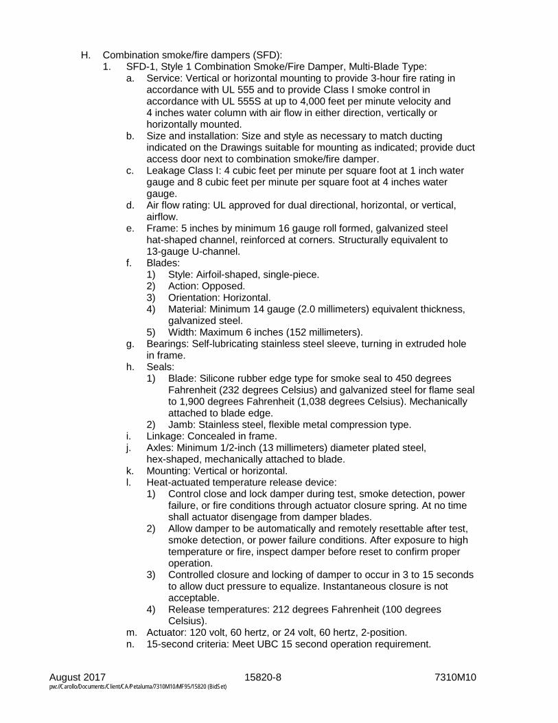
August 2017 15820-8 7310M10 pw://Carollo/Documents/Client/CA/Petaluma/7310M10/MF95/15820 (BidSet)
H. Combination smoke/fire dampers (SFD): 1. SFD-1, Style 1 Combination Smoke/Fire Damper, Multi-Blade Type:
a. Service: Vertical or horizontal mounting to provide 3-hour fire rating in accordance with UL 555 and to provide Class I smoke control in accordance with UL 555S at up to 4,000 feet per minute velocity and 4 inches water column with air flow in either direction, vertically or horizontally mounted.
b. Size and installation: Size and style as necessary to match ducting indicated on the Drawings suitable for mounting as indicated; provide duct access door next to combination smoke/fire damper.
c. Leakage Class I: 4 cubic feet per minute per square foot at 1 inch water gauge and 8 cubic feet per minute per square foot at 4 inches water gauge.
d. Air flow rating: UL approved for dual directional, horizontal, or vertical, airflow.
e. Frame: 5 inches by minimum 16 gauge roll formed, galvanized steel hat-shaped channel, reinforced at corners. Structurally equivalent to 13-gauge U-channel.
f. Blades: 1) Style: Airfoil-shaped, single-piece. 2) Action: Opposed. 3) Orientation: Horizontal. 4) Material: Minimum 14 gauge (2.0 millimeters) equivalent thickness,
galvanized steel. 5) Width: Maximum 6 inches (152 millimeters).
g. Bearings: Self-lubricating stainless steel sleeve, turning in extruded hole in frame.
h. Seals: 1) Blade: Silicone rubber edge type for smoke seal to 450 degrees
Fahrenheit (232 degrees Celsius) and galvanized steel for flame seal to 1,900 degrees Fahrenheit (1,038 degrees Celsius). Mechanically attached to blade edge.
2) Jamb: Stainless steel, flexible metal compression type. i. Linkage: Concealed in frame. j. Axles: Minimum 1/2-inch (13 millimeters) diameter plated steel,
hex-shaped, mechanically attached to blade. k. Mounting: Vertical or horizontal. l. Heat-actuated temperature release device:
1) Control close and lock damper during test, smoke detection, power failure, or fire conditions through actuator closure spring. At no time shall actuator disengage from damper blades.
2) Allow damper to be automatically and remotely resettable after test, smoke detection, or power failure conditions. After exposure to high temperature or fire, inspect damper before reset to confirm proper operation.
3) Controlled closure and locking of damper to occur in 3 to 15 seconds to allow duct pressure to equalize. Instantaneous closure is not acceptable.
4) Release temperatures: 212 degrees Fahrenheit (100 degrees Celsius).
m. Actuator: 120 volt, 60 hertz, or 24 volt, 60 hertz, 2-position. n. 15-second criteria: Meet UBC 15 second operation requirement.

August 2017 15820-9 7310M10 pw://Carollo/Documents/Client/CA/Petaluma/7310M10/MF95/15820 (BidSet)
o. Elevated temperature qualified: Damper and actuator assembly qualified in accordance with UL 555S to elevated temperature of 450 degrees Fahrenheit (232 degrees Celsius).
p. Duct transition connection: Round, oval, or rectangular, as shown or required.
q. Duct smoke detector: UL classified, factory mounted, photoelectronic type suitable for duct velocities of 500 to 4,000 feet per minute.
r. Picture frame mounting angles: 1) 1 piece, roll formed retaining angles 1-1/2 by 2-1/2 inches. 2) Factory matched and shipped on individual damper. 3) Factory pre-punched screw holes. 4) Requires factory sleeve.
s. Factory sleeve: 1) Minimum 20 gauge thickness, minimum 17 inches length. 2) Silicone caulk factory applied to sleeve at damper frame to comply
with leakage rating requirements. t. Finish: Mill galvanized. u. Assembly: Factory assemble damper, actuator, duct smoke detector and
accessories, and furnish as a single unit in accordance with UL 555 and UL 555S.
v. Manufacturers: The following or equal: 1) Ruskin, Model FSD60-3 with EFL/SP-100 electronic resettable link
and switch package system for multiple blade fire dampers and DSDN, system sensor 2151 no flow duct smoke detector.
I. Damper operators: 1. General: Provide manual or electric damper operator for each damper
furnished; type as indicated on the Drawings. 2. Manual operators:
a. Gears or mechanical, to operate damper manually with a force not exceeding 20 pounds.
b. Provide manual operators with locking quadrant. c. Provide 3/8 inch, or larger, square double-ended drive shaft adequate for
required damper torque. d. Provide sufficient number of operators for torque required to operate
damper. 3. Electric damper operators:
a. Manufacturers: One of the following or equal: 1) Honeywell, Model M445A. 2) Johnson Controls, Model M100.
b. 2-position spring return. c. 1 internal single pole double throw auxiliary switch rated 5 ampere,
120 volt, single phase, and 60 hertz. d. Housed in die-cast aluminum case with mounting flange. e. Motor and gear train components immersed in oil. f. When required, provide auxiliary transformers factory wired to damper
operator and installed in NEMA Type 1 enclosure fastened to motor housing.

August 2017 15820-10 7310M10 pw://Carollo/Documents/Client/CA/Petaluma/7310M10/MF95/15820 (BidSet)
2.02 DIFFUSERS, GRILLES, AND REGISTERS
A. Manufacturers: 1. Provide diffusers, grilles, and registers manufactured by the same
manufacturer. 2. Diffusers, grilles, and registers: One of the following or equal. One
manufacturer's model is listed with each style, similar models from other listed vendors are acceptable: a. Titus Manufacturing Corp. b. Tuttle and Bailey. c. Kees, Inc. d. Metal Industries, Inc. (MetalAire). e. Krueger.
B. Materials: 1. For metallic ductwork: Aluminum for aluminum duct work; aluminum or
galvanized steel for galvanized steel ductwork unless specified otherwise with styles.
2. For fiberglass reinforced plastic ductwork: Fiberglass reinforced plastic where not otherwise specified.
C. Components: Include specified style with frame, clips, connectors, and other accessories necessary for mounting.
D. Appearance: Similar for units in same room or space.
E. Finishes: 1. In chlorine, hypochlorite, or sodium bisulfite storage or pumping rooms and
building exhaust systems for these areas: Coat with two 1-1/2 mils thick coats of synthetic vinyl plastic coating suitable for use in gas contaminated exhaust system including chlorine, sulfur dioxide, ozone, or a combination thereof of such gases: a. Manufacturers: One of the following or equal:
1) Bisonite M, Amercoat Number 23 and 55. 2) Plasite, 2441.
2. In laboratory room exhaust systems: Coat with 2 finish coats of synthetic resin over prime applied on clean surface suitable for use in a laboratory exhaust system: a. Manufacturers: The following or equal:
1) Carboline Eisen-Heiss. 3. In other locations, specified factory standard with the style requirements of a
color selected by Engineer from standard manufacturer's colors.
F. Supply diffuser, grille, and register styles: 1. SR-1, Supply Register Style 1:
a. Size and installation: 24 inch by 24 inch panel and frame suitable for suspended T-bar lay in ceiling.
b. Faceplate: Removable, perforated with 3/16 inch holes on 1/4 inch centers.
c. Core: Adjustable, anti-smudge flow pattern with deflection patterns as indicated on the Drawings and rectangular or round neck to ducting.

August 2017 15820-11 7310M10 pw://Carollo/Documents/Client/CA/Petaluma/7310M10/MF95/15820 (BidSet)
d. Damper: Provide opposed blade volume control damper suitable for use with ducting type; damper to be adjustable through the face of the unit.
e. Materials: Aluminum frame, core, damper, and faceplate. f. Manufacturers: The following or equal:
1) Krueger, Model 6200/6500 Series. 2. SR-2, Supply Register Style 2:
a. Size and installation: Square or rectangular size as indicated on the Drawings framed for surface mounting on gypsum or T-bar ceilings.
b. Faceplate: Removable square or rectangular pattern diffuser with gasket at frame to ceiling mount.
c. Core: Adjustable vanes with rectangular or round neck to match ducting. d. Damper: Provide opposed blade volume control damper suitable for use
with ducting type; damper to be adjustable through the face of the unit. e. Materials: Aluminum frame, core, damper, and faceplate. f. Manufacturers: The following or equal:
1) Titus, Model TDCA-AA. 3. SR-3, Supply Register Style 3:
a. Size and installation: Rectangular grille size as indicated on the Drawings framed for surface mounting on gypsum or directly mounted on exposed ducting; provide 4 inch flanged drop frame when duct mounted.
b. Faceplate: Removable grille with double deflection blades spaced at 3/4 inch; front blades parallel to long dimension; provide gasket at frame for sealing.
c. Core: Adjustable vanes with rectangular or round neck to match ducting. d. Damper: Provide opposed blade volume control damper suitable for use
with ducting type; damper to be adjustable through the face of the unit. e. Materials: Aluminum frame, core, damper, and faceplate. f. Manufacturers: The following or equal:
1) Titus, Model 272FL. 2) Krueger, Model 5880H.
4. SR-4, Supply Register Style 4: a. Size and installation: Rectangular grille size as indicated on the Drawings
framed for surface mounting on gypsum or directly mounted on exposed ducting; provide 4-inch flanged drop frame when duct mounted.
b. Faceplate: Removable grille with double deflection blades spaced at 3 inch for maximum flow and throw; front blades parallel to long dimension; provide gasket at frame for sealing.
c. Core: Adjustable vanes with rectangular or round neck to match ducting. d. Damper: Provide opposed blade volume control damper suitable for use
with ducting type; damper to be adjustable through the face of the unit. e. Materials:
1) Frame and damper: Anodic acrylic painted steel. 2) Core and faceplate: Aluminum.
f. Manufacturers: The following or equal: 1) Titus, Model 132RL.
5. SR-5, Supply Register Style 5: a. Size and installation: Square 4-way grille size as indicated on the
Drawings framed for surface mounting on gypsum, T-bar ceiling, or directly mounted on exposed ducting; provide 4 inch flanged drop frame when duct mounted.
b. Faceplate: Removable grille with 4-way field adjustable deflection blades; provide gasket at frame for sealing.

August 2017 15820-12 7310M10 pw://Carollo/Documents/Client/CA/Petaluma/7310M10/MF95/15820 (BidSet)
c. Core: Adjustable vanes with rectangular or round neck to match ducting; adjust vanes to flow pattern indicated on the Drawings.
d. Damper: Provide opposed blade volume control damper suitable for use with ducting type; damper to be adjustable through the face of the unit.
e. Materials: Steel frame, core, damper, and faceplate with baked acrylic finish.
f. Manufacturers: The following or equal: 1) Titus, Model MCD.
6. SR-6, Supply Register Style 6: a. Size and installation: Modular linear slot diffuser; length as indicated on
the Drawings suitable for ceiling surface mounting on gypsum or on T-bar ceiling.
b. Plenum and damper: Provide Titus Model FBPI, or equal, insulated plenum for duct connection; provide volume control damper on plenum inlet.
c. Face: 3/4-inch slot dimension. d. Core: Adjustable flow pattern controllers; adjust to flow pattern indicated
on the Drawings. e. Materials: Aluminum construction with steel flow pattern controllers;
provide baked acrylic finish with black flow pattern controllers. f. Manufacturers: The following or equal:
1) Titus, Model ML-38. 7. SR-7, Supply Register Style 7:
a. Size and installation: Modular linear slot diffuser for extended throw; length as indicated on the Drawings suitable for ceiling or side wall surface mounting on gypsum or T-bar ceiling.
b. Plenum and damper: Provide Titus Model FBPI, or equal, insulated plenum for duct connection; provide volume control damper on plenum inlet.
c. Face: 2-inch slot dimension. d. Core: Individually adjustable, 24-inch long flow pattern controllers over
slot length; adjust to flow pattern indicated on the Drawings. e. Materials: Aluminum; provide baked acrylic finish with black flow pattern
controllers. f. Manufacturers: The following or equal:
1) Titus, Model FL-20-JT. 8. SR-8, Supply Register Style 8:
a. Size and installation: High capacity, high throw drum louver suitable for ceiling or side wall surface mounting on gypsum or direct duct mounting; size and mounting as indicated on the Drawings; provide 4-inch flanged drop frame when duct mounted.
b. Face: Flanged with sponge rubber gasket. c. Core: Adjustable drum with felt side seals; 25- to 30-degree drum rotation
from the centerline. d. Damper: Provide opposed blade volume control damper on inlet ducting;
damper to be adjustable from the face of the grille. e. Materials: 18-gauge steel frame, aluminum drum, and damper; provide
baked acrylic finish. f. Manufacturers: The following or equal:
1) Titus, Model DL.

August 2017 15820-13 7310M10 pw://Carollo/Documents/Client/CA/Petaluma/7310M10/MF95/15820 (BidSet)
G. Return diffuser, grille, and register styles: 1. RR-1, Return Register Style 1:
a. Size and installation: 24-inch by 24-inch panel and frame suitable for suspended T-bar lay in ceiling.
b. Faceplate: Removable, perforated with 3/16 inch holes on 1/4 inch centers matching SR-1 in appearance.
c. Core: When connected to ducting, provide suitable rectangular or round neck connection to ducting type indicated on the Drawings.
d. Damper: When connected to ducting, provide opposed blade volume control damper suitable for use with ducting type; damper to be adjustable through the face of the unit.
e. Materials: Aluminum frame, core, damper, and faceplate. f. Manufacturers: The following or equal:
1) Titus, Model PAR-AA. 2. RR-2, Return Register Style 2:
a. Size and installation: Square or rectangular size as indicated on the Drawings framed for surface mounting on gypsum or T-bar ceilings.
b. Faceplate: Removable square or rectangular pattern diffuser with gasket at frame to ceiling mount; match SR-2 in appearance.
c. Core: When connected to ducting, provide suitable rectangular or round neck connection to ducting type indicated on the Drawings.
d. Damper: When connected to ducting, provide opposed blade volume control damper suitable for use with ducting type; damper to be adjustable through the face of the unit.
e. Materials: Aluminum frame, core, damper, and faceplate. f. Manufacturers: One of the following or equal:
1) Titus, Model TDC-AA. 2) Krueger, Model 6290/6590 Series.
3. RR-3, Return Register Style 3: a. Size and installation: Rectangular grille with size as indicated on the
Drawings framed for surface mounting on gypsum or directly mounted on exposed ducting; provide 4 inch flanged drop frame when duct mounted.
b. Faceplate: Removable grille with fixed blades spaced at 3/4 inch; front blades parallel to long dimension with 35 degree deflection; provide gasket at frame for sealing.
c. Core: When connected to ducting, provide suitable rectangular or round neck to match ducting; when filter indicated on the Drawings, provide 1 inch deep filter frame and hinged face with 1/4 turn fasteners.
d. Damper: When connected to ducting, provide opposed blade volume control damper suitable for use with ducting type; damper to be adjustable through the face of the unit.
e. Materials: Aluminum frame, core, damper, and faceplate. f. Manufacturers: The following or equal:
1) Titus, Model 350FL or Model 350FF1. 4. RR-4, Return Register Style 4:
a. Size and installation: Size as indicated on the Drawings suitable for ceiling or sidewall surface mounting on gypsum or T-bar ceiling.
b. Face: High free area eggcrate with 1/2 inch by 1/2 inch by 1 inch deep grid.
c. Core: When connected to ducting, provide suitable rectangular or round neck to match ducting; when filter indicated on the Drawings, provide 1-inch deep filter frame and hinged face.

August 2017 15820-14 7310M10 pw://Carollo/Documents/Client/CA/Petaluma/7310M10/MF95/15820 (BidSet)
d. Damper: When connected to ducting, provide opposed blade volume control damper suitable for use with ducting type; damper to be adjustable through the face of the unit.
e. Materials: Aluminum frame, core, damper, and faceplate. f. Manufacturers: The following or equal:
1) Titus, Model 50F or 50FF. 5. RR-5, Return Register Style 5:
a. Size and installation: Size as indicated on the Drawings suitable for ceiling or sidewall surface mounting on gypsum.
b. Face: Perforated screen with framed boarder; 3/16 inch holes on 1/4-inch centers.
c. Core: When connected to ducting, provide suitable rectangular or round neck to match ducting; when filter indicated on the Drawings, provide 1-inch deep filter frame and hinged face.
d. Damper: When connected to ducting, provide opposed blade volume control damper suitable for use with ducting type; damper to be adjustable through the face of the unit.
e. Materials: Aluminum frame, core, damper, and faceplate. f. Manufacturers: The following or equal:
1) Titus, Model 8F or 8FF. 6. RR-6, Return Register Style 6:
a. Service: Return air in corrosive environments. b. Size and installation: Square grille size from 6 by 6 inches to 12 by
12 inches, size as indicated on the Drawings framed for surface mounting on gypsum or directly mounted on exposed ducting; provide 4-inch flanged drop frame when duct mounted.
c. Faceplate: Eggcrate square pattern on 1/2 inch centers; provide gasket at frame for sealing.
d. Core: Rectangular neck; provide transition as required to match ducting. e. Damper: Provide opposed blade volume control damper suitable for use
with ducting type; damper to be adjustable through the face of the unit. f. Materials: Engineered PVC material achieving a Class 94 V-0 fire rating
and in accordance with NFPA 90B and NFPA 255 for frame, core, damper, and faceplate; finish to be matte white.
g. Manufacturers: The following or equal: 1) Metal Industries, Model EPCC5 with Model OBDP damper.
H. Door or partition grille: 1. DG-1, Door or Partition Grille Style 1:
a. Size and installation: Size as indicated on the Drawings suitable for mounting on wood doors.
b. Face and frame: 1.25 inch boarder surface mount boarder with inverted V, site proof blades parallel to the long dimension; countersunk screw holes; provide faceplate on both sides of penetration.
c. Materials: Aluminum frame and blades with baked acrylic finish. d. Manufacturers: The following or equal:
1) Titus, Model CT-700-LF.
2.03 SCREENS
A. Characteristics and features: 1. Bird screen: 1/2-inch mesh by 14 gauges.
August 2017 15820-15 7310M10 pw://Carollo/Documents/Client/CA/Petaluma/7310M10/MF95/15820 (BidSet)
2. Insect screens: 18 by 14 mesh. 3. Screens and frames, same material as ductwork, hood, louver, fan, or
equipment connected to screen. 4. Screens secured in frames.
2.04 FLEXIBLE CONNECTIONS
A. Provide flexible duct connectors at all connections to fans and other air movement equipment as indicated on the Drawings.
B. FL-1, Duct to Duct Flexible Connection: 1. Fabric shall be fire resistant, waterproof, mildew-resistant, and airtight. At least
4 inches of fabric shall be exposed. Flexible connections shall be in accordance with the requirements of UL and NFPA.
2. Interior locations: a. Fabric for flexible connections installed inside office areas shall be
Neoprene coated glass fabric suitable for a temperature range of -20 degrees Fahrenheit to 180 degrees Fahrenheit and shall have a weight of at least 27 ounces per square yard and a thickness of 0.024 inches.
b. Manufacturers: The following or equal: 1) Ventfabrics “Ventglas”.
3. Exterior locations: a. Fabric for flexible connections exposed to sunlight or the weather shall be
glass fabric coated with chlorosulfurated polyethylene suitable for a temperature range of -10 degrees Fahrenheit to 250 degrees Fahrenheit and shall have a weight of at least 24 ounces per square yard and a thickness of 0.019 inches.
b. Manufacturers: The following or equal: 1) Ventfabrics “Ventlon”.
C. FL-2, Duct to Duct Flexible Connection, Corrosive Environment: 1. Fabric for flexible connections exposed to chemicals shall be glass fabric
coated with Teflon and suitable for a temperature range of -10 degrees Fahrenheit to 500 degrees Fahrenheit and shall have a weight of at least 14 ounces per square yard and a thickness of 0.014 inches.
2. Manufacturers: The following or equal: a. Ventfabrics “Ventel”.
D. FL-3, Duct to Equipment Heavy Duty Flexible Connection: 1. Materials: EPDM rubber vulcanized with minimum of 1 ply of reinforcing fabric;
3/16 inch thick. 2. Unit shall have minimum movement of:
a. Axial compression: 2.25 inches. b. Axial extension: 1.25 inches. c. Lateral offset: 1.25 inches.
3. Provide 3/8 inch thick by 2 inch wide pre-drilled retaining rings/back-up bars to clamp the expansion joints into the ducting system.
4. The expansion joint shall be of fully molded construction. Splices will not be allowed in the body of the expansion joint.
5. Manufacturers: One of the following or equal: a. Proco Series 500, Style 530 Fabric Fan Connector.

August 2017 15820-16 7310M10 pw://Carollo/Documents/Client/CA/Petaluma/7310M10/MF95/15820 (BidSet)
b. Holz Rubber Style 952 Arch Design Expansion Joint.
PART 3 EXECUTION
3.01 PREPARATION
A. Before installation, remove dust and debris from ducts and accessories.
3.02 INSTALLATION
A. Install items in accordance with manufacturer’s instructions.
B. FL-3, Flexible Connections: Install at connections between duct and air handling equipment and at locations indicated on the Drawings.
C. FL-1 and FL-2, Flexible Connections: 1. Install at building expansion joints and as indicated on the Drawings. 2. Install with collar and metal band to form airtight joints. 3. Install with minimum 4 inches of slack in fabric. 4. Exterior locations: Install sheet metal weather cover over fabric. 5. Duct alignment shall be a maximum of 1/2 inch offset. 6. The minimum/maximum gap shall be 2-inches and 6-inches. 7. Lap longitudinal joints and glue per manufacturer’s recommendations.
3.03 FIELD QUALITY CONTROL
A. Set grilles, dampers, and diffusers to achieve flows and flow patterns indicated on the Drawings and test finished system as specified in Section 15954.
B. Mark final balance positions on all manual damper actuators with paint pen in a distinctive color.
END OF SECTION

August 2017 15954-1 7310M10 pw://Carollo/Documents/Client/CA/Petaluma/7310M10/MF95/15954 (BidSet)
SECTION 15954
TESTING, ADJUSTING, AND BALANCING FOR HVAC
PART 1 GENERAL
1.01 SUMMARY
A. Section includes: 1. Heating, ventilation, and air conditioning systems testing, adjusting, and
balancing.
B. Related sections: 1. Section 01756 - Commissioning.
1.02 REFERENCES
A. Associated Air Balance Council (AABC): 1. National Standards for Field Measurements and Instrumentation, Total System
Balance, Air Distribution-Hydronic Systems.
B. National Environmental Balancing Bureau (NEBB): 1. Procedural Standards for Testing, Adjusting, and Balancing Environmental
Systems.
C. Sheet Metal and Air Conditioning Contractors' National Association (SMACNA): 1. Heating, Ventilating, and Air Conditioning Systems - Testing, Adjusting, and
Balancing.
D. Testing, Adjusting, and Balancing Bureau (TABB): 1. International Standards for Environmental Systems Balance.
1.03 TESTING, ADJUSTING, AND BALANCING WORK REQUIREMENTS
A. Procure the services of an independent air balance and testing agency belonging to and in good standing with the AABC, NEBB, or the TABB to perform air and hydronic balancing, testing, and adjustment of building and process air conditioning, heating, and ventilating air systems.
B. The Work includes: Balancing new air and hydronic systems installed as part of this contract and existing air and hydronic systems affected by the installation of new equipment.
C. Perform testing of heating, ventilating, and air conditioning equipment, balancing of distribution systems, and adjusting of air terminal units and ductwork accessories to ensure compliance with Specifications and Drawings. Perform tests for following: 1. Air conditioning units. 2. Heat pump units. 3. Central station air handlers. 4. Evaporative coolers. 5. Heating units.

August 2017 15954-2 7310M10 pw://Carollo/Documents/Client/CA/Petaluma/7310M10/MF95/15954 (BidSet)
6. Fans. 7. Odor scrubber fans. 8. Condensers. 9. Air terminal units. 10. Ductwork accessories. 11. Ducting. 12. HVAC controls. 13. Other specified HVAC equipment.
D. Test hydronic systems, and adjust and record liquid flow at each piece of equipment to ensure compliance with Specifications and the Drawings. Perform test for following: 1. Circulating pumps. 2. Circuit setting valves. 3. 3-way mixing valves. 4. Hot water coils. 5. Chilled water coils. 6. Other specified hydronic system components.
E. Test each mode of operation of thermostats, electronic controllers, and pneumatic, electric or electronic heating, ventilating, and air conditioning instruments to ensure operation as specified.
F. Test and adjust room distribution patterns at air outlets.
G. Provide instruments required for testing, adjusting, and balancing operations; retain possession of instruments; remove instruments from site at completion of services.
H. Make instruments available to the Engineer to facilitate spot checks during testing.
I. Provide test holes for pressure and pitot flow measurements; provide plugs for all test holes after testing.
1.04 QUALITY ASSURANCE
A. Test, balance, and adjust environmental systems in accordance with either: 1. AABC: National Standards for Field Measurements and Instrumentation, Total
Systems Balance, Air Distribution-Hydronics System. 2. NEBB: Procedural Standards for Testing, Adjusting, and Balancing of
Environmental Systems. 3. TABB: International Standards for Environmental Systems Balance.
B. Perform services under direction of AABC, NEBB, or TABB certified supervisor.
C. Calibrate and maintain instruments in accordance with requirements of standards. Make calibration histories of instruments available for examination.
D. Make measurements in accordance with accuracy requirements of standards.
E. Testing, adjusting, and balancing performance requirements: 1. Comply with procedural standards of certifying association. 2. Execute each step of prescribed testing, balancing, and adjusting procedures
without omission.

August 2017 15954-3 7310M10 pw://Carollo/Documents/Client/CA/Petaluma/7310M10/MF95/15954 (BidSet)
3. Accurately record required data. 4. Make measurements in accordance with recognized procedures and practices
of certifying association. 5. Measure air volume discharged at each outlet and adjust air outlets to design
air volumes within 5 percent over.
1.05 SUBMITTALS
A. Resumes of proposed supervisor and personnel showing training and qualifications.
B. Interim reports: At least 30 days prior to starting field work, submit the following: 1. Set of report forms filled out as to design flow values and installed equipment
pressure drops, and required cubic feet per minute for air terminals. 2. Develop heating, ventilating, and air conditioning system schematic similar to
Figure 6-1 in SMACNA Testing, Adjusting, and Balancing. 3. Complete list of instruments proposed to be used, organized in appropriate
categories, with data sheets for each showing: a. Manufacturer and model number. b. Description and use when needed to further identify instrument. c. Size or capacity range. d. Latest calibration date.
C. Final report: At least 15 days prior to Contractor's request for final inspection, submit 3 copies of final reports, on applicable reporting forms. Include: 1. Identify instruments which were used and last date of calibration of each. 2. Procedures followed to perform testing, adjusting, and balancing. 3. Identification and succinct description of systems included in report. 4. Initial balance test results made with all dampers and air control devices in full
open positions. 5. Description of final locations and sizes, including opening area and
dimensioned configuration of orifices and other restrictions used to achieve final balanced flows.
6. Description of final location and opening positions of dampers, registers, louvers, and valves.
7. Schematics of systems included in report; use schematics as part of testing, adjusting, and balancing report to summarize design and final balanced flows.
8. Testing, adjusting, and balancing report forms. 9. Final field results established for system balancing including airflow, fan
speeds, and fan static pressures at the fan inlet and outlet. 10. Appendices. 11. Include appendices for:
a. Raw field data taken during testing. b. Sample calculation sheet for each type of calculation made to convert raw
field data to final results. c. Initial air balance results with dampers and registers in full open position;
include airflow at all inlets and outlet, initial fan speed and fan suction and discharge pressures.
D. Proposed schedule for testing and balancing.
E. Provide Manufacturer’s Certificate of Installation and Functionality Compliance as specified in Section 01756.

August 2017 15954-4 7310M10 pw://Carollo/Documents/Client/CA/Petaluma/7310M10/MF95/15954 (BidSet)
1.06 SITE CONDITIONS
A. Prior to start of testing, adjusting, and balancing, verify that: 1. Systems installation is complete and in full operation. 2. Outside conditions are within reasonable range relative to design conditions. 3. Lighting fixtures are energized. 4. Special equipment such as computers, laboratory equipment, and electronic
equipment are in full operation. 5. Requirements for preparation for testing and balancing have been met for
elements of each system which require testing.
PART 2 PRODUCTS Not Used.
PART 3 EXECUTION
3.01 FIELD QUALITY CONTROL
A. Perform Functional Tests as specified in Section 01756.
B. Testing, adjusting, and balancing acceptance criteria: Consider testing, adjusting, and balancing procedures successful and complete when heating, ventilating, and air conditioning systems and components are functioning properly and system air and water flows are within specified tolerances of design flows.
3.02 TESTING, ADJUSTING, AND BALANCING
A. Test, adjust, and balance separate complete heating, ventilating, and air conditioning systems.
B. Include in testing, adjusting, and balancing related existing heating, ventilating, and air conditioning components.
C. Perform testing, adjusting, and balancing cycles until airflows meet acceptance criteria. 1. Ascertain airflow balance between overall requirements and flow in individual
supply and exhaust grilles.
D. Initial testing, adjusting, and balancing: Perform first test on each system with dampers, grilles, orifices, and other variable airflow devices in their full open position; measure and report initial airflows, fan speed, and fan static pressures at fan inlet and outlet. 1. Adjust total system flow downward or upward by adjusting fan speed until
1 inlet or outlet is at indicated flow and all other flows exceed indicated flows. 2. Adjust fan speed by changing fan drives or sheaves as necessary.

August 2017 15954-5 7310M10 pw://Carollo/Documents/Client/CA/Petaluma/7310M10/MF95/15954 (BidSet)
E. Subsequent testing, adjusting, and balancing: Perform adjustments in subsequent testing, adjusting, and balancing by adjusting dampers, louvers, or size of orifices or plates. 1. Measure and record air volume discharged at each inlet and outlet and adjust
air inlets and outlets to design air volumes within 0 to 5 percent over design rates.
2. Adjust fan speeds and motor drives within drive limitations, for required air volume.
3. Measure cubic feet per minute and static pressures and adjust air supply and exhaust fan units to deliver at least 100 to 105 percent of the design air volume.
4. Measure and record static air pressure conditions on fans, including filter and coil pressure drops, and total pressure across the fan.
5. Evaluate building and room pressure conditions to determine adequate supply and return air conditions.
6. Evaluate space and zone temperature of conditions to determine adequate performance of the systems to maintain temperatures without draft.
7. Permanently mark final balance positions of balancing dampers.
F. Develop heating, ventilating, and air conditioning system schematics similar to Figure 6-1 in SMACNA Testing, Adjusting, and Balancing.
G. Accurately record the required data on AABC, NEBB, or TABB test and balance report forms.
H. Measure amperage draw of fan and pump motors for final balance.
I. Following completion of balancing procedures for air systems, test, adjust, and balance hydronic systems. 1. Measure flow and adjust circuit setter valves so pumps deliver at least
100 percent of the design water flow. 2. Measure and adjust water flow at coils for design conditions, within 5 percent.
Check conditions at cooling and heating coils for required performance at design conditions.
3. Lock balance valves in the adjusted position and permanently mark the design set point. a. Record valve settings in the design report.
J. Test primary source equipment in accordance with AABC, NEBB, or TABB procedures. 1. Primary source equipment includes items listed in this Section not previously
tested as part of this testing, adjusting, and balancing work. 2. Complete appropriate AABC, NEBB, or TABB equipment test forms for each
piece of equipment. 3. Calculate cooling and heating capacities to show conformance with specified
capacities. 4. Adjust equipment as needed to deliver specified cooling and heating loads. 5. Record final equipment performing characteristics and adjustment settings in
the final design report.
END OF SECTION


August 2017 15956-1 7310M10 pw://Carollo/Documents/Client/CA/Petaluma/7310M10/MF95/15956 (BidSet)
SECTION 15956
PIPING SYSTEMS TESTING
PART 1 GENERAL
1.01 SUMMARY
A. Section includes: Test requirements for piping systems.
B. Related sections: 1. Section 01330 - Submittal Procedures. 2. Section 01410 - Regulatory Requirements. 3. Section 01500 - Temporary Facilities and Controls. 4. Section 15052 - Common Work Results for General Piping.
1.02 REFERENCES
A. National Fuel Gas Code (NFGC).
B. American Society of Mechanical Engineers (ASME): 1. B31.1 - Power Piping. 2. B31.3 - Process Piping. 3. B31.8 - Gas Transmission and Distribution Piping Systems.
C. Underwriters Laboratories Inc. (UL).
1.03 TESTING REQUIREMENTS
A. General requirements: 1. Testing requirements are stipulated in Laws and Regulations; are included in
the Piping Schedule in Section 15052; are specified in the specifications covering the various types of piping; and are specified in this Section.
2. Requirements in Laws and Regulations supersede other requirements of Contract Documents, except where requirements of Contract Documents are more stringent, including higher test pressures, longer test times, and lower leakage allowances.
3. Test plumbing piping in accordance with Laws and Regulations, the plumbing code, as specified in Section 01410, and UL requirements.
4. Test natural gas or digester gas piping: a. For less than 125 pounds per square inch gauge working pressure, test in
accordance with mechanical code, as specified in Section 01410, or the National Fuel Gas Code, whichever is more stringent.
b. For 125 pounds per square inch gauge or greater working pressure, test per ASME B31.3 or ASME B31.8, whichever is more stringent.
5. When testing with water, the specified test pressure is considered to be the pressure at the lowest point of the piping section under test. a. Lower test pressure as necessary (based on elevation) if testing is
performed at higher point of the pipe section.

August 2017 15956-2 7310M10 pw://Carollo/Documents/Client/CA/Petaluma/7310M10/MF95/15956 (BidSet)
B. Furnish necessary personnel, materials, and equipment, including bulkheads, restraints, anchors, temporary connections, pumps, water, pressure gauges, and other means and facilities required to perform tests.
C. Water for testing, cleaning, and disinfecting: 1. Water for testing, cleaning, and disinfecting will be provided as specified in
Section 01500.
D. Pipes to be tested: Test only those portions of pipes that have been installed as part of this Contract. Test new pipe sections prior to making final connections to existing piping. Furnish and install test plugs, bulkheads, and restraints required to isolate new pipe sections. Do not use existing valves as test plug or bulkhead.
E. Unsuccessful tests: 1. Where tests are not successful, correct defects or remove defective piping and
appurtenances and install piping and appurtenances that comply with the specified requirements.
2. Repeat testing until tests are successful.
F. Test completion: Drain and leave piping clean after successful testing.
G. Test water disposal: Dispose of testing water at the Stormwater Pump Station in accordance with requirements of federal, state, county, and city regulations governing disposal of wastes in the location of the Project and disposal site.
1.04 SUBMITTALS
A. Submit as specified in Section 01330.
B. Schedule and notification of tests: 1. Submit a list of scheduled piping tests by noon of the working day preceding
the date of the scheduled tests. 2. Notification of readiness to test: Immediately before testing, notify Engineer in
writing of readiness, not just intention, to test piping. 3. Have personnel, materials, and equipment specified in place before submitting
notification of readiness.
1.05 SEQUENCE
A. Clean piping before pressure or leak tests.
B. Test gravity piping underground, including sanitary sewers, for visible leaks before backfilling and compacting.
C. Underground pressure piping may be tested before or after backfilling when not indicated or specified otherwise.
D. Backfill and compact trench, or provide blocking that prevents pipe movement before testing underground piping with a maximum leakage allowance.
E. Test underground piping before encasing piping in concrete or covering piping with slab, structure, or permanent improvement.

August 2017 15956-3 7310M10 pw://Carollo/Documents/Client/CA/Petaluma/7310M10/MF95/15956 (BidSet)
PART 2 PRODUCTS Not Used.
PART 3 EXECUTION
3.01 TESTING ALIGNMENT, GRADE, AND DEFLECTION
A. Alignment and grade: 1. Visually inspect the interior of gravity piping with artificial light, reflected light,
or laser beam. 2. Consider inspection complete when no broken or collapsed piping, no open or
poorly made joints, no grade changes that affect the piping capacity, or no other defects are observed.
B. Deflection test: 1. Pull a mandrel through the clean piping section under test. 2. Perform the test not sooner than 30 days after installation and not later than
60 days after installation. 3. Use a 9-rod mandrel with a contact length of not less than the nominal
diameter of the pipe within 1 percent plus or minus. 4. Consider test complete when the mandrel can be pulled through the piping
with reasonable effort by 1 person, without the aid of mechanical equipment.
3.02 AIR TESTING METHOD FOR PRESSURE PIPING
A. Air test piping, indicated with "AM" in the Piping Schedule, with air or another nonflammable or inert gas.
B. Test gas, air, liquefied petroleum gas, liquid chlorine, and chlorine gas piping by the air test method: 1. Test chlorine piping with dry air or nitrogen having a dew point of minus
40 degrees Fahrenheit or less. Supply temporary air dryers as necessary.
C. Test at pressure as specified in Piping Schedule in Section 15052: 1. Provide temporary pressure relief valve for piping under test:
a. Set at the lesser of 110 percent of the test pressure or 50 pounds per square inch gauge over the test pressure.
2. Air method test pressures shall not exceed 110 percent of the piping maximum allowable working pressure calculated in accordance with the most stringent of ASME B31.1, ASME B31.3, ASE B31.8, or the pipe manufacturer's stated maximum working pressure.
3. Gradually increase test pressure to an initial test pressure equal to the lesser of 1/2 the test pressure or 25 pounds per square inch gauge.
4. Perform initial check of joints and fittings for leakage. 5. Gradually increase test pressure in steps no larger than the initial pressure.
Check for leakage at each step increase until test pressure reached. 6. At each step in the pressure, examine and test piping being air tested for leaks
with soap solution. 7. Consider examination complete when piping section under test holds the test
pressure for 15 minutes without losses.

August 2017 15956-4 7310M10 pw://Carollo/Documents/Client/CA/Petaluma/7310M10/MF95/15956 (BidSet)
3.03 TESTING GRAVITY FLOW PIPING
A. Test gravity flow piping indicated with "GR" in the Piping Schedule, as follows: 1. Unless specified otherwise, subject gravity flow piping to the following tests:
a. Alignment and grade. b. For plastic piping test for deflection. c. Visible leaks and pressure with maximum leakage allowance, except for
storm drains and culverts. 2. Inspect piping for visible leaks before backfilling. 3. Provide temporary restraints when needed to prevent movement of piping. 4. Pressure test piping with maximum leakage allowance after backfilling. 5. With the lower end plugged, fill piping slowly with water while allowing air to
escape from high points. Keep piping full under a slight head for the water at least 24 hours: a. Examine piping for visible leaks. Consider examination complete when no
visible leaks are observed. b. Maintain piping with water, or allow a new water absorption period of
24 hours for the performance of the pressure test with maximum leakage allowance.
c. After successful completion of the test for visible leaks and after the piping has been restrained and backfilled, subject piping to the test pressure for minimum of 4 hours while accurately measuring the volume of water added to maintain the test pressure: 1) For polyvinyl chloride (PVC) gravity sewer pipe: 25 gallons per day
per inch diameter per mile of piping under test: a) Consider the test complete when leakage is equal to or less
than the following maximum leakage allowances: (1) For concrete piping with rubber gasket joints: 80 gallons per
day per inch of diameter per mile of piping under test: (a) Advise manufacturer of concrete piping with rubber
gasket joints of more stringent than normal maximum leakage allowance.
(2) For vitrified clay piping: 500 gallons per day per inch of diameter per mile of piping under test.
(3) For other piping: 80 gallons per day per inch diameter per mile of piping under test.
3.04 TESTING HIGH-HEAD PRESSURE PIPING
A. Test piping for which the specified test pressure in the Piping Schedule is 20 pounds per square inch gauge or greater, by the high head pressure test method, indicated "HH" in the Piping Schedule.
B. General: 1. Test connections, hydrants, valves, blowoffs, and closure pieces with the
piping. 2. Do not use installed valves for shutoff when the specified test pressure
exceeds the valve's maximum allowable seat differential pressure. Provide blinds or other means to isolate test sections.
3. Do not include valves, equipment, or piping specialties in test sections if test pressure exceeds the valve, equipment, or piping specialty safe test pressure allowed by the item's manufacturer.

August 2017 15956-5 7310M10 pw://Carollo/Documents/Client/CA/Petaluma/7310M10/MF95/15956 (BidSet)
4. During the performance of the tests, test pressure shall not vary more than plus or minus 5 pounds per square inch gauge with respect to the specified test pressure.
5. Select the limits of testing to sections of piping. Select sections that have the same piping material and test pressure.
6. When test results indicate failure of selected sections, limit tests to piping: a. Between valves. b. Between a valve and the end of the piping. c. Less than 500 feet long.
7. Test piping for minimum 2 hours for visible leaks test and minimum 2 hours for the pressure test with maximum leakage allowance.
C. Testing procedures: 1. Fill piping section under test slowly with water while venting air:
a. Use potable water for all potable waterlines and where noted on the Piping Schedule.
2. Before pressurizing for the tests, retain water in piping under slight pressure for a water absorption period of minimum 24 hours.
3. Raise pressure to the specified test pressure and inspect piping visually for leaks: a. Consider visible leakage testing complete when no visible leaks are
observed.
D. Pressure test with maximum leakage allowance: 1. Leakage allowance is zero for piping systems using flanged, National Pipe
Thread threaded and welded joints. 2. Pressure test piping after completion of visible leaks test. 3. For piping systems using joint designs other than flanged, threaded, or welded
joints, accurately measure the makeup water necessary to maintain the pressure in the piping section under test during the pressure test period: a. Consider the pressure test to be complete when makeup water added is
less than the allowable leakage and no damage to piping and appurtenances has occurred.
b. Successful completion of the pressure test with maximum leakage allowance shall have been achieved when the observed leakage during the test period is equal or less than the allowable leakage and no damage to piping and appurtenances has occurred.
c. When leakage is allowed, calculate the allowable leakage by the following formula: L = S x D x P1/2 x 133,200-1 wherein the terms shall mean: L = Allowable leakage in gallons per hour. S = Length of the test section in feet. D = Nominal diameter of the piping in inches. P = Average observed test pressure in pounds per square inches gauge, at the lowest point of the test section, corrected for elevation of the pressure gauge. x = The multiplication symbol.
August 2017 15956-6 7310M10 pw://Carollo/Documents/Client/CA/Petaluma/7310M10/MF95/15956 (BidSet)
3.05 TESTING LOW-HEAD PRESSURE PIPING
A. Test piping for which the specified test pressure is less than 20 pounds per square inch gauge, by the low head pressure test method, indicated "LH" in the Piping Schedule.
B. General: 1. Test pressures shall be as scheduled in Section 15052. 2. During the performance of the tests, test pressure shall not vary more than
plus or minus 2 pounds per square inch gauge with respect to the specified test pressure.
3. Test connections, blowoffs, vents, closure pieces, and joints into structures, including existing bell rings and other appurtenances, with the piping.
4. Test piping for minimum 2 hours for visible leaks test and minimum 2 hours for the pressure test with maximum leakage allowance.
C. Visible leaks test: 1. Subject piping under test to the specified pressure measured at the lowest
end. 2. Fill piping section under test slowly with water while venting air:
a. Use potable water for all potable waterlines and where noted on the Piping Schedule.
3. Before pressurizing for the tests, retain water in piping under slight pressure for the water absorption period of minimum 24 hours.
4. Raise pressure to the specified test pressure and inspect piping visually for leaks. Consider testing complete when no visible leaks are observed.
D. Pressure test with maximum leakage allowance: 1. Pressure test piping after completion of visible leaks test. 2. Accurately measure the makeup water necessary to maintain the pressure in
the piping section under test during the pressure test period: a. Consider the pressure test to be complete when makeup water added is
less than the allowable leakage of 80 gallons per inch of nominal diameter, per mile of piping section under test after 24 hours, and no damage to piping and appurtenances has occurred.
b. Successful completion of the leakage test shall have been achieved when the observed leakage is equal or less than the allowable leakage and no damage to piping and appurtenances has occurred.
E. Optional joint test: 1. When joint testing is allowed by note in the Piping Schedule, the procedure
shall be as follows: a. Joint testing will be allowed only for low head pressure piping. b. Joint testing does not replace and is not in lieu of any testing of the piping
system or trust restraints. 2. Joint testing may be performed with water or air. 3. Joint test piping after completion of backfill and compaction to the top of the
trench. 4. Joint testing with water:
a. Measure test pressure at the invert of the pipe. Apply pressure of 4 feet plus the inside diameter of the pipe in water column within 0.20 feet in water column.
August 2017 15956-7 7310M10 pw://Carollo/Documents/Client/CA/Petaluma/7310M10/MF95/15956 (BidSet)
b. Maintain test pressure for 1 minute. c. Base the allowable leakage per joint on 80 gallons per inch nominal
diameter, per mile of piping, per 24 hours equally distributed to the actual number of joints per mile for the type of piping.
d. Consider the pressure test to be complete when makeup water added is less than the allowable leakage.
e. Successful completion of the joint test with water shall have been achieved when the observed leakage is equal or less than the allowable leakage.
5. Joint testing with air: a. Apply test pressure of 3 pounds per square inch gauge with a maximum
variation of plus 0.20 and minus 0.00 pounds per square inch. b. Maintain test pressure for 2 minutes. c. Consider the pressure test to be complete when the test pressure does
not drop below 2.7 pounds per square inch for the duration of the test.
END OF SECTION


August 2017 15958-1 7310M10 pw://Carollo/Documents/Client/CA/Petaluma/7310M10/Specifications/15958 (BidSet)
SECTION 15958
MECHANICAL EQUIPMENT TESTING
PART 1 GENERAL
1.01 SUMMARY
A. Section includes: Testing of mechanical equipment and systems.
B. Related sections: 1. Section 01756 - Commissioning. 2. Section 15956 - Piping Systems Testing. 3. Section 16222 - Low Voltage Motors up to 500 Horsepower.
1.02 REFERENCES
A. American National Standards Institute (ANSI): 1. S1.4 Specification for Sound Level Meters.
B. Hydraulic Institute (HI).
C. National Institute of Standards and Technology (NIST).
1.03 SUBMITTALS
A. Project closeout documents: 1. Provide vendor operation and maintenance manual as specified in
Section 01782. a. Include motor rotor bar pass frequencies for motors larger than
500 horsepower.
PART 2 PRODUCTS Not Used.
PART 3 EXECUTION
3.01 GENERAL
A. Commissioning of equipment as specified in: 1. This Section. 2. Section 01756. 3. Equipment sections:
a. If testing requirements are not specified, provide Level 1 Tests.
B. Comply with latest version of applicable standards.
C. Test and prepare piping as specified in Section 15956.
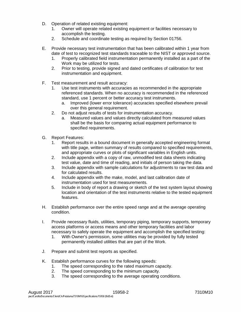
August 2017 15958-2 7310M10 pw://Carollo/Documents/Client/CA/Petaluma/7310M10/Specifications/15958 (BidSet)
D. Operation of related existing equipment: 1. Owner will operate related existing equipment or facilities necessary to
accomplish the testing. 2. Schedule and coordinate testing as required by Section 01756.
E. Provide necessary test instrumentation that has been calibrated within 1 year from date of test to recognized test standards traceable to the NIST or approved source. 1. Properly calibrated field instrumentation permanently installed as a part of the
Work may be utilized for tests. 2. Prior to testing, provide signed and dated certificates of calibration for test
instrumentation and equipment.
F. Test measurement and result accuracy: 1. Use test instruments with accuracies as recommended in the appropriate
referenced standards. When no accuracy is recommended in the referenced standard, use 1 percent or better accuracy test instruments. a. Improved (lower error tolerance) accuracies specified elsewhere prevail
over this general requirement. 2. Do not adjust results of tests for instrumentation accuracy.
a. Measured values and values directly calculated from measured values shall be the basis for comparing actual equipment performance to specified requirements.
G. Report Features: 1. Report results in a bound document in generally accepted engineering format
with title page, written summary of results compared to specified requirements, and appropriate curves or plots of significant variables in English units.
2. Include appendix with a copy of raw, unmodified test data sheets indicating test value, date and time of reading, and initials of person taking the data.
3. Include appendix with sample calculations for adjustments to raw test data and for calculated results.
4. Include appendix with the make, model, and last calibration date of instrumentation used for test measurements.
5. Include in body of report a drawing or sketch of the test system layout showing location and orientation of the test instruments relative to the tested equipment features.
H. Establish performance over the entire speed range and at the average operating condition.
I. Provide necessary fluids, utilities, temporary piping, temporary supports, temporary access platforms or access means and other temporary facilities and labor necessary to safely operate the equipment and accomplish the specified testing: 1. With Owner's permission, some utilities may be provided by fully tested
permanently installed utilities that are part of the Work.
J. Prepare and submit test reports as specified.
K. Establish performance curves for the following speeds: 1. The speed corresponding to the rated maximum capacity. 2. The speed corresponding to the minimum capacity. 3. The speed corresponding to the average operating conditions.

August 2017 15958-3 7310M10 pw://Carollo/Documents/Client/CA/Petaluma/7310M10/Specifications/15958 (BidSet)
3.02 PUMP TESTS, ALL LEVELS OF TESTING
A. Test in accordance with the following: 1. Applicable HI Standards. 2. This Section. 3. Equipment sections.
B. Test tolerances: In accordance with appropriate HI Standards, except the following modified tolerances apply: 1. From 0 to plus 5 percent of head at the specified flows. 2. From 0 to plus 5 percent of flow at the rated design point head. 3. No negative tolerance for the efficiency at the specified flows. 4. No positive tolerance for vibration limits. Vibration limits and test methods in HI
Standards do not apply, use limits and methods specified in this or other Sections of the Specifications.
3.03 DRIVERS TESTS
A. Test motors as specified in Section 16222.
B. Test other drivers as specified in the equipment section.
3.04 NOISE REQUIREMENTS AND CONTROL
A. Perform noise tests in conjunction with vibration test analysis.
B. Make measurements in relation to reference pressure of 0.0002 microbar.
C. Make measurements of emitted noise levels on sound level meter meeting or exceeding ANSI S1.4, Type II.
D. Set sound level meter to slow response.
E. Unless otherwise specified, maximum free field noise level not to exceed 85 dBA measured as sound pressure level at 3 feet from the equipment.
3.05 PRESSURE TESTING
A. Hydrostatically pressure test pressure containing parts at the appropriate standard or code required level above the equipment component specified design pressure or operating pressure, whichever is higher.
3.06 INSPECTION AND BALANCING
A. Statically and dynamically balance each of the individual rotating parts as required to achieve the required field vibration limits.
B. Statically and dynamically balance the completed equipment rotating assembly and drive shaft components.
C. Furnish copies of material and component inspection reports including balancing reports for equipment system components and for the completed rotating assembly.

August 2017 15958-4 7310M10 pw://Carollo/Documents/Client/CA/Petaluma/7310M10/Specifications/15958 (BidSet)
D. Critical speed of rotating equipment: 1. Satisfy the following:
a. The first lateral and torsional critical speed of all constant, variable, and 2-speed driven equipment that is considered rigid such as horizontal pumps, all non-clog pumps, blowers, air compressors, and engines shall be at least 25 percent above the equipment’s maximum operating speed.
b. The first lateral and torsional critical speed of all constant, variable, and 2-speed driven equipment that is considered flexible or flexibly mounted such as vertical pumps (vertical in-line and vertical non-clog pumps excluded) and fans shall at least 25 percent below the equipment’s lowest operating speed.
c. The second lateral and torsional critical speed of all constant, variable, and 2-speed equipment that is considered flexible or flexibly mounted shall be at least 25 percent above the maximum operating speed.
E. Vibration tests: 1. Definitions:
a. Root mean square: for pumps operating at speeds greater than 600 rpm, the vibration measurement shall be measured as the overall velocity in inches per second root mean square (RMS).
b. Peak-to-peak displacement: The root means squared average of the peak-to-peak displacement multiplied by the square root of 2.
c. Peak velocity: The root mean squared average of the peak velocity multiplied by the square root of 2.
d. Peak acceleration: The root mean squared average of the peak acceleration multiplied by the square root of 2.
e. High frequency enveloping: A process to extract very low amplitude time domain signals associated with impact or impulse events such as bearing or gear tooth defects and display them in a frequency spectrum of acceleration versus frequency. 1) Manufacturers: One of the following or equal:
a) Rockwell Automation, Entek Group, "Spike Energy" analysis. b) CSI, "PeakVue."
f. Low speed equipment: Equipment or components of equipment rotating at less than 600 revolutions per minute.
g. High speed equipment: Equipment and equipment components operating at or above 600 revolutions per minute.
h. Preferred operating range: Manufacturer’s defined preferred operating range (POR) for the equipment.
i. Allowable operating range: Manufacturer’s defined allowable operating range (AOR) for the equipment.
2. Vibration instrumentation requirements: a. Analyzers: Use digital type analyzers or data collectors with anti-aliasing
filter, 12 bit A/D converter, fast fourier transform circuitry, phase measurement capability, time wave form data storage, high frequency enveloping capabilities, 35 frequency ranges from 21 to 1,500,000 cycles per minute, adjustable fast fourier transform resolution from 400 to 6,400 lines, storage for up to one hundred 3,200 line frequency spectra, data output port, circuitry for integration of acceleration data to velocity or double integration to displacement. 1) Manufacturers: One of the following or equal:

August 2017 15958-5 7310M10 pw://Carollo/Documents/Client/CA/Petaluma/7310M10/Specifications/15958 (BidSet)
a) Computational Systems Inc., (CSI) Division of Emerson Process Management, Model 2120A, Data Collector/analyzer with applicable analysis software.
b) Pruftechnik, VIBXPERT II. b. Analyzer settings:
1) Units: English, inches/second, mils, and gravitational forces. 2) Fast fourier transform lines: Most equipment 1,600 minimum; for
motors, enough lines as required to distinguish motor current frequencies from rotational frequencies, use 3,200 lines for motors with a nominal speed of 3,600 revolutions per minute; 3,200 lines minimum for High Frequency Enveloping; 1,600 lines minimum for low speed equipment.
3) Sample averages: 4 minimum. 4) Maximum frequency (Fmax): 40 times rotational frequency for rolling
element bearings, 10 times rotational frequency for sleeve bearings. 5) Amplitude range: Auto select but full scale not more than twice the
acceptance criteria or the highest peak, whichever is lower. 6) Fast fourier transform windowing: Hanning Window. 7) High pass filter: Minus 3 dB at 120 cycles per minute for high speed
equipment. Minus 3 dB at 21 cycles per minute for low speed equipment.
c. Accelerometers: 1) For low speed equipment: Low frequency, shear mode
accelerometer, 500 millivolts per gravitational force sensitivity, 10 gravitational force range, plus/minus 5 percent frequency response from 0.5 hertz to 850 hertz, magnetic mount. a) Manufacturers: One of the following or equal:
(1) Wilcoxon Research, Model 797L. (2) PCB, Model 393C.
2) For high speed equipment: General purpose accelerometer, 100 millivolts per gravitational force sensitivity, 50 gravitational force range, plus/minus 3dB frequency response range from 2 hertz to 12,000 hertz when stud mounted, with magnetic mount holder. a) Manufacturers: One of the following or equal:
(1) Wilcoxon Research, Model 793. (2) Entek-IRD Model 943.
3. Accelerometer mounting: a. Use magnetic mounting or stud mounting. b. Mount on bearing housing in location with best available direct path to
bearing and shaft vibration. c. Remove paint and mount transducer on flat metal surface or epoxy mount
for High Frequency Enveloping measurements. 4. Vibration acceptance criteria:
a. Testing of rotating mechanical equipment: Tests are to be performed by an experienced, factory trained, and independent authorized vibration analysis expert.
b. Vibration displacement limits: Unless otherwise specified, equipment operating at speeds 600 revolutions per minute or less is not to exhibit unfiltered readings in excess of following:

August 2017 15958-6 7310M10 pw://Carollo/Documents/Client/CA/Petaluma/7310M10/Specifications/15958 (BidSet)
Operating Conditions and Application Data Overall Peak-to-Peak Displacement
Field, mils Factory, mils Operation within the POR 3.0 4.0
Operation within the AOR 4.0 5.0
Additive value when measurement location is greater than 5 feet above foundation. 2.0 2.0
Additive value for solids-handling pumps 2.0 N/A
Additive value for slurry pumps 2.0 N/A c. Vibration velocity limits: Unless otherwise specified, equipment operating
at speeds greater than 600 revolutions per minute is not to exceed the following peak velocity limits:
HI Pump Type Horsepower Field Test Factory Test
Overall RMS Overall RMS
Horizontal Solids Handling Centrifugal Pumps
Below 33 hp 0.25 0.28
Horizontal and Vertical In-Line Centrifugal Pumps (other than Non-Clog type) Vertical Solids Handling Centrifugal Pumps
Between 33 and 100 hp 0.28 0.31
100 hp and above 0.31 0.34
Below 33 hp 0.30 0.33
Vertical Turbine, Mixed Flow, and Propeller Pumps
Between 33 and 100 hp 0.32 0.35
100 hp and above 0.34 0.35
Non-Solids Handling Centrifugal Pumps HI Types BB1, BB2, BB3, BB4, BB5, OH1, OH2, OH3, OH4, OH5, and OH7
Below 268 hp 0.15 0.19
268 hp and above 0.19 0.22
Vertical Turbine, Mixed Flow, and Propeller Pumps HI Types VS1, VS2, VS3, VS4, VS5, VS6, VS7, and VS8
Below 268 hp 0.13
Gear Reducers, Radial 268 hp and above 0.17
Slurry Pumps 0.25 0.30
Motors See Applicable Motor
Specification
See Applicable Motor
Specification
Gear Reducers, Radial Not to exceed AGMA 6000-
B96 limits
Not to exceed AGMA 6000-
B96 limits
Other Reducers, Axial 0.1 N/A

August 2017 15958-7 7310M10 pw://Carollo/Documents/Client/CA/Petaluma/7310M10/Specifications/15958 (BidSet)
d. Equipment operation: Measurements are to be obtained with equipment installed and operating within capacity ranges specified and without duplicate equipment running.
e. Additional criteria: 1) No narrow band spectral vibration amplitude components, whether
sub-rotational, higher harmonic, or synchronous multiple of running speed, are to exceed 40 percent of synchronous vibration amplitude component without manufacturer's detailed verification of origin and ultimate effect of such excitation.
2) The presence of discernable vibration amplitude peaks in Test Level 2 or 3 vibration spectra at bearing inner or outer race frequencies shall be cause for rejection of the equipment.
3) For motors, the following shall be cause for rejection: a) Stator eccentricity evidenced by a spectral peak at 2 times
electrical line frequency that is more than 40 percent of the peak at rotational frequency.
b) Rotor eccentricity evidenced by a spectral peak at 2 times electrical line frequency with spectra side bands at the pole pass frequency around the 2 times line frequency peak.
c) Other rotor problems evidenced by pole pass frequency side bands around operating speed harmonic peaks or 2 times line frequency side bands around rotor bar pass frequency or around 2 times the rotor bar pass frequency.
d) Phasing problems evidenced by 1/3 line frequency side band spectral peaks around the 2 times electrical line frequency peak.
4) The presence of peaks in a High Frequency Enveloping spectra plot corresponding to bearing, gear or motor rotor bar frequencies or harmonics of these frequencies shall be cause for rejection of the equipment; since inadequate lubrication of some equipment may be a cause of these peaks, lubrication shall be checked, corrected as necessary and the high frequency envelope analysis repeated.
5. Vibration testing results presentation: a. Provide equipment drawing with location and orientation of measurement
points indicated. b. For each vibration measurement take and include appropriate data on
equipment operating conditions at the time vibration data is taken; for pumps, compressors, and blowers record suction pressure, discharge pressure, and flow.
c. When Vibration Spectra Data required: 1) Plot peak vibration velocity versus frequency in cycles per minute. 2) Label plots showing actual shaft or part rotation frequency, bearing
inner and outer race ball pass frequencies, gear mesh frequencies and relevant equipment excitation frequencies on the plot; label probable cause of vibration peaks whether in excess of specification limits or not.
3) Label plots with equipment identification and operating conditions such as tag number, capacity, pressure, driver horsepower, and point of vibration measurement.
4) Plot motor spectra on a log amplitude scale versus frequency. d. For low speed equipment, plot peak vibration displacement versus
frequency as well as velocity versus frequency.

August 2017 15958-8 7310M10 pw://Carollo/Documents/Client/CA/Petaluma/7310M10/Specifications/15958 (BidSet)
e. Provide name of manufacturer and model number of the vibration instrumentation used, including analyzer and accelerometer used together with mounting type.
3.07 TESTING LEVELS
A. Level 1 Tests: 1. Level 1 General Equipment Performance Test:
a. For equipment, operate, rotate, or otherwise functionally test for 15 minutes minimum after components reach normal operating temperatures.
b. Operate at rated design load conditions. c. Confirm that equipment is properly assembled, equipment moves or
rotates in the proper direction, shafting, drive elements, and bearings are installed and lubricated in accordance with proper tolerances, and that no unusual power consumption, lubrication temperatures, bearing temperatures, or other conditions are observed.
2. Level 1 Pump Performance Test: a. Measure flow and head while operating at or near the rated condition; for
factory testing, testing may be at reduced speeds with flow and head corresponding to the rated condition when adjusted for speed using the appropriate affinity laws.
b. Use of a test driver is permitted for factory tests when actual driver is given a separate test at its point of manufacture as specified in Section 16222 or the applicable equipment section. Use actual driver for field tests.
c. Record measured flow, suction pressure, discharge pressure, and make observations on bearing temperatures and noise levels.
3. Level 1 Vibration Test: a. Test requirement:
1) Measure filtered vibration spectra versus frequency in 3 perpendicular planes at each normally accessible bearing housing on the driven equipment, any gears and on the driver; 1 plane of measurement to be parallel to the axis of rotation of the component.
2) Vibration spectra versus frequency shall be in accordance with Vibration Acceptance Criteria.
b. Equipment operating condition: Test at specified maximum speed. 4. Level 1 Noise Test:
a. Measure unfiltered overall A-weighted sound pressure level in dBA at 3 feet horizontally from the surface of the equipment and at a mid-point of the equipment height.
B. Level 2 Tests: 1. Level 2 General Performance Test:
a. For equipment, operate, rotate, or otherwise functionally test for at least 2 hours after components reach normal operating temperatures.
b. Operate at rated design load conditions. c. Confirm that equipment is properly assembled, equipment moves or
rotates in the proper direction, shafting, drive elements, and bearings are installed and lubricated in accordance with proper tolerances, and that no unusual power consumption, lubrication temperatures, bearing temperatures, or other conditions are observed.

August 2017 15958-9 7310M10 pw://Carollo/Documents/Client/CA/Petaluma/7310M10/Specifications/15958 (BidSet)
2. Level 2 Pump Performance Test: a. Test 2 hours minimum for flow and head at the rated condition; for factory
testing, testing may be at a reduced speeds with flow and head corresponding to the rated condition when adjusted for speed using the appropriate affinity laws.
b. Use of a test driver is permitted for factory tests when actual driver is given a separate test at its point of manufacture as specified in Section 16222. Use actual driver for field tests.
c. Test for flow and head at 2 additional conditions; 1 at 25 percent below the rated flow and 1 at 10 percent above the rated flow.
d. Record measured flow, suction pressure, discharge pressure, and observations on bearing temperatures and noise levels at each condition.
3. Level 2 Vibration Test: a. Test requirement:
1) Measure filtered vibration spectra versus frequency and measure vibration phase in 3 perpendicular planes at each normally accessible bearing housing on the driven equipment, any gears and on the driver; 1 plane of measurement to be parallel to the axis of rotation of the component; measure actual rotational speeds for each vibration spectra measured using photometric or other tachometer input connected directly to the vibration data collector.
2) Vibration spectra versus frequency shall be in accordance with Vibration Acceptance Criteria.
b. Equipment operating condition: Repeat test requirements at design specified maximum speed and at minimum speed for variable speed equipment.
c. Natural frequency test of field installed equipment: 1) Excite the installed equipment and support system in 3 perpendicular
planes, use same planes as operating vibration measurement planes, and determine the as-installed natural resonant frequency of the driven equipment, the driver, gears, and supports.
2) Perform test at each bearing housing, at each support pedestal, and for pumps on the suction and discharge piping.
3) Perform with equipment and attached piping full of intended service or process fluid.
4. Level 2 Noise Test: a. Measure filtered A-weighted overall sound pressure level in dBA for each
of 8 octave band mid-points beginning at 63 hertz measured at 3 feet horizontally from the surface of the equipment at mid-point height of the noise source.
C. Level 3 Tests: 1. Level 3 General Equipment Performance Tests:
a. For equipment, operate, rotate, or otherwise functionally test for at least 4 hours after components reach normal operating temperatures.
b. Operate at rated design load conditions for 1/2 the specified time; operate at each of any other specified conditions for a proportionate share of the remaining test time.
c. Confirm that equipment is properly assembled, equipment rotates in the proper direction, shafting and bearings are installed and lubricated in accordance with proper tolerances, and that no unusual noise, vibration, or temperatures are observed.

August 2017 15958-10 7310M10 pw://Carollo/Documents/Client/CA/Petaluma/7310M10/Specifications/15958 (BidSet)
d. Take appropriate capacity, power or fuel consumption, torque, revolutions per minute, pressure, and temperature readings using appropriate test instrumentation to confirm equipment meets specified performance requirements at the design rated condition.
e. Bearing temperatures: During maximum speed or capacity performance testing, measure and record the exterior surface temperature of each bearing versus time.
2. Level 3 Pump Performance Test: a. Test 4 hours minimum for flow and head at or near the rated condition; for
factory testing, testing may be at a reduced speeds with flow and head corresponding to the rated condition when adjusted for speed using the appropriate affinity laws.
b. Use of a test driver is permitted for factory tests when actual driver is given a separate test at its point of manufacture as specified in Section 16222. Use actual driver for field tests.
c. Test each specified flow and head condition at the rated speed and test at minimum as well as maximum specified speeds; operate at each test condition for a minimum of 15 minutes; for factory testing, test at other speeds may be omitted if test driver at reduced speeds is used for rated condition testing.
d. Record measured shaft revolutions per minute, flow, suction pressure, discharge pressure; record measured bearing temperatures (bearing housing exterior surface temperatures may be recorded when bearing temperature devices are not required by the equipment section) and record observations on noise levels.
3. Level 3 Vibration Test: a. Requirements: Same as Level 2 vibration test except data taken at each
operating condition tested and with additional requirements below. b. Perform High Frequency Enveloping Analysis for gears and bearings.
1) Measure bearing element vibration directly on each bearing cap in a location close as possible to the bearing load zone that provides a smooth surface and direct path to the bearing to detect bearing defects.
2) Report results in units of acceleration versus frequency in cycles per minute.
c. Perform Time Wave Form analysis for gears, low speed equipment and reciprocating equipment; plot true peak amplitude velocity and displacement versus time and label the period between peaks with the likely cause of the periodic peaks (relate the period to a cause).
d. Plot vibration spectra on 3 different plots; peak displacement versus frequency, peak acceleration versus frequency and peak velocity versus frequency.
4. Level 3 Noise Test: Measure filtered, un-weighted overall sound pressure level in dB at 3 feet horizontally from the surface of the equipment at mid-point height and at 4 locations approximately 90 degrees apart in plan view; report results for each of 8 octave band mid-points beginning at 63 hertz.
D. Level 4 Tests: 1. Level 4 General Equipment Performance Test:
a. For equipment, operate, rotate, or otherwise functionally test for at least 8 hours after components reach normal operating temperatures.

August 2017 15958-11 7310M10 pw://Carollo/Documents/Client/CA/Petaluma/7310M10/Specifications/15958 (BidSet)
b. Operate at rated design load conditions for 1/2 the specified time; operate at each of any other specified conditions for a proportionate share of the remaining test time.
c. Confirm that equipment is properly assembled, equipment rotates in the proper direction, shafting and bearings are installed and lubricated in accordance with proper tolerances, and that no unusual noise, vibration, or temperatures are observed.
d. Take appropriate capacity, power or fuel consumption, torque, revolutions per minute, pressure and temperature readings, using appropriate test instrumentation to confirm equipment meets specified performance requirements at the design rated condition.
e. Bearing temperatures: During maximum speed or capacity testing, measure and record the exterior surface temperature of each bearing versus time.
2. Level 4 Pump Performance Test: a. Test 8 hours minimum for flow and head; begin tests at or near the rated
condition; for factory and field-testing, test with furnished motor at full speed.
b. Test each specified flow and head condition at the rated speed and test at minimum as well as maximum specified speeds; operate at each test condition for a minimum of 20 minutes or longer as necessary to measure required performance, vibration, and noise data at each test condition.
c. Record measured shaft revolutions per minute, flow, suction pressure, discharge pressure; record measured bearing temperatures (bearing housing exterior surface temperatures may be recorded when bearing temperature devices not required by the equipment section) and record observations on noise levels.
d. Bearing temperatures: During maximum speed or capacity testing, measure and record the exterior surface temperature of each bearing versus time.
e. Perform efficiency and/or Net Positive Suction Head Required (NPSHr) and/or priming time tests when specified in the equipment section in accordance with the appropriate HI standard and as follows: 1) Perform NPSHr testing at maximum rated design speed, head and
flow with test fluids at ambient conditions; at maximum rated speed, test at 15 percent above rated design flow, and 25 percent below rated design flow.
2) Perform efficiency testing with test fluids at maximum rated speed. 3) Perform priming time testing with test fluids at maximum rated speed.
3. Level 4 Vibration Test: Same as Level 3 vibration test. 4. Level 4 Noise Test: Same as Level 3 Noise Test except with data taken at
each operating condition tested.
END OF SECTION


August 2017 16050-1 7310M10 pw://Carollo/Documents/Client/CA/Petaluma/7310M10/Specifications/16050 (BidSet)
SECTION 16050
COMMON WORK RESULTS FOR ELECTRICAL
PART 1 GENERAL
1.01 SUMMARY
A. Section includes: 1. General requirements applicable to all Electrical Work. 2. General requirements for electrical submittals.
B. Related sections: 1. Instructions to Bidders. 2. General Conditions. 3. Section 01140 - Work Restrictions. 4. Section 01292 - Schedule of Values. 5. Section 01312 - Project Meetings. 6. Section 01324B - Progress Schedules and Reports. 7. Section 01329 - Safety Plan. 8. Section 01330 - Submittal Procedures. 9. Section 01410 - Regulatory Requirements. 10. Section 01450 - Quality Control. 11. Section 01500 - Temporary Facilities and Controls. 12. Section 01600 - Product Requirements. 13. Section 01610 - Project Design Criteria. 14. Section 01612 - Seismic Design Criteria. 15. Section 01614 - Wind Design Criteria. 16. Section 01738 - Selective Site Demolition. 17. Section 01756 - Commissioning. 18. Section 01770 - Closeout Procedures. 19. Section 01782 - Operation and Maintenance Data 20. Section 16075 - Identification for Electrical Systems. 21. Section 16130 - Conduits. 22. Section 16262 - Variable Frequency Drives 0.50- 50 Horsepower. 23. Section 16422 - Motor Starters. 24. Section 16950 - Field Electrical Acceptance Tests.
C. Interfaces to equipment, instruments, and other components: 1. The Drawings, Specifications, and overall design are based on preliminary
information furnished by various equipment manufacturers which identify a minimum scope of supply from the manufacturers. This information pertains to, but is not limited to, instruments, control devices, electrical equipment, packaged mechanical systems, and control equipment provided with mechanical systems.
2. Provide all material and labor needed to install the actual equipment furnished, and include all costs to add any additional conduit, wiring, terminals, or other electrical hardware to the Work, which may be necessary to make a complete, functional installation based on the actual equipment furnished: a. Make all changes necessary to meet the manufacturer’s wiring
requirements.
August 2017 16050-2 7310M10 pw://Carollo/Documents/Client/CA/Petaluma/7310M10/Specifications/16050 (BidSet)
3. Submit all such changes and additions to the Engineer for acceptance as specified in General Conditions.
4. Review the complete set of Drawings and Specifications in order to ensure that all items related to the electrical power and control systems are completely accounted for. Include any such items that appear on the Drawings or in the Specifications from another discipline in the scope of Work: a. If a conflict between Drawings and Specifications is discovered, refer
conflict to the Engineer as soon as possible for resolution. 5. Loop drawings:
a. Provide all electrical information required in the preparation of loop drawings including, but not limited to: 1) Conduit numbers and associated signal(s) contained within each
conduit. 2) Wire numbers. 3) Equipment terminal numbers. 4) Junction boxes and signal(s) contained within each junction box. 5) Equipment power sources, and associated circuit numbers. 6) As-built drawings detailing wiring.
D. All electrical equipment and systems for the entire Project must comply with the requirements of the Electrical Specifications, whether referenced in the individual Equipment Specifications or not: 1. The requirements of the Electrical Specifications apply to all Electrical Work
specified in other sections. 2. Inform all vendors supplying electrical equipment or systems of the
requirements of the Electrical Specifications. 3. Owner is not responsible for any additional costs due to the failure of
Contractor to notify all subcontractors and suppliers of the Electrical Specifications requirements.
E. Contract Documents: 1. General:
a. The Drawings and Specifications are complementary and are to be used together in order to fully describe the Work.
2. Specifications: a. The General and Special Conditions of the Contract Documents govern
the Work. b. These requirements are in addition to all General Requirements.
3. Contract Drawings: a. The Electrical Drawings show desired locations, arrangements, and
components of the Electrical Work in a diagrammatic manner. b. Locations of equipment, control devices, instruments, boxes, panels, etc.
are approximate only; exercise professional judgment in executing the Work to ensure the best possible installation: 1) The equipment locations and dimensions indicated on the Drawings
are approximate. Use the shop drawings to determine the proper layout, foundation, and pad requirements, etc. for final installation. Coordinate with all subcontractors to ensure that all electrical equipment is compatible with other equipment and space requirements. Make changes required to accommodate differences in equipment dimensions.

August 2017 16050-3 7310M10 pw://Carollo/Documents/Client/CA/Petaluma/7310M10/Specifications/16050 (BidSet)
2) The Contractor has the freedom to select any of the named manufacturers identified in the individual specification sections; however, the Engineer has designed the spatial equipment layout based upon a single manufacturer and has not confirmed that every named manufacturer’s equipment fits in the allotted space. It is the Contractor’s responsibility to ensure that the equipment being furnished fits within the defined space.
c. Installation details: 1) The Contract Drawings include typical installation details the
Contractor is to use to complete the Electrical Work. For cases where a typical detail does not apply, develop installation details that may be necessary for completing the Work, and submit these details for review by the Engineer.
2) Not all typical installation details are referenced within the Drawing set. Apply and use typical details where appropriate.
d. Schematic diagrams: 1) All controls are shown de-energized. 2) Schematic diagrams show control function only. Incorporate other
necessary functions for proper operation and protection of the system.
3) Add slave relays, where required, to provide all necessary contacts for the control system or where needed to function as interposing relays for control voltage coordination, equipment coordination, or control system voltage drop considerations.
4) Mount all devices shown on motor controller schematic diagrams in the controller compartment enclosure, unless otherwise noted or indicated.
5) Schematic diagrams are to be used in conjunction with the descriptive operating sequences in the Contract Documents. Combine all information and furnish a coordinated and fully functional control system.
F. Alternates/Alternatives: 1. Coordinate with General Conditions for substitute item provisions.
G. Changes and change orders: 1. As specified in General Conditions.
1.02 REFERENCES
A. Code compliance: 1. As specified in Section 01410. 2. The publications are referred to in the text by the basic designation only. The
latest edition accepted by the Authority Having Jurisdiction of referenced publications in effect at the time of the bid governs.
3. The standards listed are hereby incorporated into this Section. a. American National Standards Institute (ANSI). b. American Society of Civil Engineers (ASCE):
1) ASCE 7 - Minimum Design Loads for Buildings and Other Structures. c. ASTM International (ASTM). d. Illuminating Engineering Society (IES). e. Institute of Electrical and Electronics Engineers (IEEE).

August 2017 16050-4 7310M10 pw://Carollo/Documents/Client/CA/Petaluma/7310M10/Specifications/16050 (BidSet)
f. Insulated Cable Engineers Association (ICEA). g. International Code Council (ICC).
1) International Code Council Evaluation Service (ICC-ES). a) AC 156 – Acceptance Criteria for Seismic Certification by Shake
Table Testing of Non-Structural Components (ICC-ES AC 156). h. International Society of Automation (ISA). i. National Electrical Manufacturers Association (NEMA):
1) 250 - Enclosures for Electrical Equipment (1000 V Maximum). j. National Fire Protection Association (NFPA):
1) 70 - National Electrical Code (NEC). k. National Institute of Standards and Technology (NIST). l. Underwriters' Laboratories, Inc. (UL).
B. Compliance with laws and regulations: 1. As specified in the General Conditions.
1.03 DEFINITIONS
A. Definitions of terms and other electrical and instrumentation considerations as set forth by: 1. IEEE. 2. NETA. 3. IES. 4. ISA. 5. NEC. 6. NEMA. 7. NFPA. 8. NIST.
B. Specific definitions: 1. FAT: Factory acceptance test. 2. ICSC: Instrumentation and controls subcontractor. 3. LCP: Local control panel: Operator interface panel that may contain an HMI,
pilot type control devices, operator interface devices, control relays, etc. and does not contain a PLC or RIO.
4. PCM: Process control module: An enclosure containing any of the following devices: PLC, RTU, or RIO.
5. PCIS: Process control and instrumentation system. 6. RTU: Remote telemetry unit: A controller typically consisting of a PLC, and a
means for remote communications. The remote communications devices typically are radios, modems, etc.
7. Space: That portion of the switchgear, motor control center, panelboard, switchboard or control panel that does not physically contain a device but is capable of accepting a device with no modifications to the equipment, i.e., provide all standoffs, bus, and hardware, as part of the space.
8. Spare: That portion of the switchgear, motor control center, panelboard, switchboard or control panel that physically contains a device with no load connections to be made.
9. VCP: Vendor control panel: Control panels that are furnished with particular equipment by a vendor other than the ICSC. These panels may contain PLCs, RIO, OIT, HMI, etc.

August 2017 16050-5 7310M10 pw://Carollo/Documents/Client/CA/Petaluma/7310M10/Specifications/16050 (BidSet)
10. Unequipped space: That portion of the switchgear, motor control center, panelboard, switchboard or control panel that does not physically contain a device, standoff, bus, hardware, or other equipment.
1.04 SYSTEM DESCRIPTION
A. General requirements: 1. The Work includes everything necessary for and incidental to executing and
completing the Electrical Work indicated on the Drawings and specified in the Specifications and reasonably inferable there from: a. The Electrical Drawings are schematic in nature; use the Structural,
Mechanical, and Civil Drawings for all dimensions and scaling purposes. 2. It is the intent of these Specifications that the entire electrical power,
instrumentation, and control system be complete and operable. Provide all necessary material and labor for the complete system from source of power to final utilization equipment, including all connections, testing, calibration of equipment furnished by others as well as equipment furnished by the Contractor, whether or not specifically mentioned but which are necessary for successful operation.
3. Provide all Electrical Work, including conduit, field wiring, and connections by the electrical subcontractor under the provisions of the Electrical Specifications for all aspects of the Work.
4. Coordinate all aspects of the Work with the electrical subcontractor and other subcontractors before bidding in order to ensure that all costs associated with a complete installation are included. The Owner is not responsible for any change orders due to lack of coordination of the Work between the Contractor, the electrical subcontractor, the other subcontractors or suppliers.
5. Demolition: a. Where demolition is specified or indicated on the Drawings, disconnect all
associated electrical equipment and render the equipment safe. b. Remove and dispose of all conduit, wire, electrical equipment, controls,
etc. associated with the items and/or areas to be demolished as indicated on the Drawings unless otherwise indicated.
c. Salvage electrical equipment as specified in Section 01738. d. For each piece of equipment to be removed, remove all ancillary
components (e.g. instruments, solenoid valves, disconnect switches, etc.). e. Conduit:
1) Where conduit removal, other than associated with equipment to be removed, is indicated on the Drawings: a) Remove exposed conduit to the point of encasement or burial. b) Cut conduit flush and plug or cap encased or buried conduit.
2) Where conduits are to remain in place and removal is not indicated on the Drawings: a) Cap conduit open ends. b) Re-label empty conduits as spare.
f. Remove all wire back to the source for all conduits to be removed or abandoned in place.
g. Provide new nameplates for modified electrical distribution equipment, motor control centers etc. to identify equipment and circuits that are no longer used as spares.
h. Provide new typewritten schedules for all modified panelboards.

August 2017 16050-6 7310M10 pw://Carollo/Documents/Client/CA/Petaluma/7310M10/Specifications/16050 (BidSet)
6. Portions of this Project involve installation in existing facilities and interfaces to existing circuits, power systems, controls, and equipment: a. Perform and document comprehensive and detailed field investigations of
existing conditions (circuits, power systems, controls, equipment, etc.) before starting any Work. Determine all information necessary to document, interface with, modify, upgrade, or replace existing circuits, power systems, controls, and equipment.
b. Provide and document interface with, modifications to, upgrades, or replacement of existing circuits, power systems, controls, and equipment.
7. Provide all trenching, forming, rebar, concrete, back filling, hard surface removal and replacement, for all items associated with the Electrical Work and installation: a. As specified in the Contract Documents.
8. Defective work: a. As specified in the General Conditions.
B. Modified systems: 1. Demolition of the existing screw press and associated equipment. Replace
with new screw press and associated equipment. 2. The Work includes modifications to 15-MCC-A and 16-MCC-A to support new
HSW equipment.
C. Operating facility: 1. As specified in Section 01140. 2. The Ellis Creek WRF is an operating facility. Portions of this facility must
remain fully functional throughout the entire construction period. In consideration of this requirement, comply with the following guidelines: a. All outages must be of minimal duration and fully coordinated and agreed
to by the Owner. Adjust the construction schedule to meet the requirements of the Owner. All changes in schedule and any needs to reschedule are included in the Work.
b. As weather and water demand conditions dictate, re-adjust the construction schedule to meet the demands placed upon Owner by its users.
c. Coordinate the construction and power renovation, bear all costs, so that all existing facilities can continue operation throughout construction.
3. According to individual circumstances and in compliance with the Drawings, extend or replace conduit and cable connections from existing locations.
4. The standards of documentation, instrument tagging, cable and conductor ferruling, terminal identification and labeling that apply to the new installation apply equally to the existing installation which forms part of the modified system.
1.05 SUBMITTALS
A. Furnish submittals as specified in Section 01330 and this Section.
B. General: 1. Instruct all equipment suppliers of submittals and operation and maintenance
manuals of the requirements in this Section. 2. Furnish the submittals required by each section in the Electrical Specifications.

August 2017 16050-7 7310M10 pw://Carollo/Documents/Client/CA/Petaluma/7310M10/Specifications/16050 (BidSet)
3. Adhere to the wiring numbering scheme specified in Section 16075 throughout the Project: a. Uniquely number each wire. b. Wire numbers must appear on all Equipment Drawings.
4. Use equipment and instrument tags, as indicated on the Drawings, for all submittals.
C. Seismic requirements: 1. Provide electrical equipment with construction and anchorage to supporting
structures designed to resist site seismic loads based on the seismic design criteria in Section 01612.
2. For equipment installed in structures designated as seismic design category C, D, E or F, prepare and submit the following: a. Statement of seismic qualification, and special seismic certification:
1) “Statement of seismic qualification:” Provide manufacturer’s statement that the equipment satisfies the seismic design requirements of the building code indicated in Section 01410, including the requirements of ASCE 7, Chapter 13.
2) “Special seismic certification:” Provide manufacturer’s certification that the equipment, when subjected to shake table testing in accordance with ICC-ES AC 156, meets the “Post-Test Functional Compliance Verification” requirements of ICC-ES AC 156 for “Components with Ip = 1.5.” Compliance shall include both operability and containment of hazardous materials as appropriate to the unit being tested.
b. Substantiating test data: With seismic qualification and special seismic certification statements, submit results of testing in accordance with ICC-ES AC 156.
c. Anchoring design calculations and details: 1) Submit project-specific drawings and supporting calculations,
prepared and sealed by a professional engineer licensed in the state where the Project is being constructed, and showing details for anchoring electrical equipment to its supports and for anchoring supports provided with the equipment to the structure. Prepare calculations in accordance with the requirements of Section 01612.
3. Exemptions: A “statement of seismic qualification” and a “special seismic certification” are not required for the following equipment: a. Temporary or moveable equipment. b. Equipment anchored to the structure and having a total weight of
20 pounds or less. c. Distribution equipment anchored to the structure and having a total unit
weight of 3 pounds per linear foot, or less.
D. Operation and maintenance manuals: 1. As specified in Section 01782. 2. Furnish the Engineer with a complete set of written operation and maintenance
manuals 8 weeks before Functional Acceptance Testing.
E. Material and equipment schedules: 1. Furnish a complete schedule and/or matrix of all materials, equipment,
apparatus, and luminaries that are proposed for use:

August 2017 16050-8 7310M10 pw://Carollo/Documents/Client/CA/Petaluma/7310M10/Specifications/16050 (BidSet)
a. Include sizes, names of manufacturers, catalog numbers, and such other information required to identify the items.
F. Schedule of values: 1. In addition to completing all items referred to in the schedule of values,
Section 01292, submit per unit material and labor costs used in developing the final bid for the electrical system, for the express purpose of pricing and cost justification for any proposed change orders. In addition to the items shown on the schedule of values, provide per unit material and labor costs for conduit and wire installation for specific types, sizes, and locations as indicated on the Drawings and Conduit Schedule. It is the responsibility of the electrical subcontractor to prove to the Engineer’s satisfaction that said per unit costs were used in the development of the final Bid amount.
G. Record Documents: 1. Furnish as specified in Section 01770.
H. Test reports: 1. As specified in Section 01330. 2. Additional requirements for field acceptance test reports are specified in
Sections 01756 and 16950.
I. Calculations: 1. Where required by specific Electrical Specifications:
a. Because these calculations are being provided by a registered professional engineer, they will be reviewed for form, format, and content but will not be reviewed for accuracy and calculation means.
1.06 QUALITY ASSURANCE
A. Furnish all equipment listed by and bearing the label of UL or of an independent testing laboratory acceptable to the Engineer and the Authority Having Jurisdiction.
1.07 DELIVERY, STORAGE, AND HANDLING
A. As specified in Section 01600.
1.08 PROJECT OR SITE CONDITIONS
A. Site conditions: 1. Provide an electrical, instrumentation and control system, including all
equipment, raceways, and any other components required for a complete installation that meets the environmental conditions for the Site as specified in the General Requirements and below.
2. Seismic load resistance: a. Provide electrical equipment with construction and anchorage to
supporting structures designed to resist site seismic loads as specified in Section 01612.
3. Wind load resistance: a. Provide electrical equipment with construction and anchorage to
supporting structures designed to resist site wind loads as specified in Section 01614.
4. Altitude, temperature and humidity:

August 2017 16050-9 7310M10 pw://Carollo/Documents/Client/CA/Petaluma/7310M10/Specifications/16050 (BidSet)
a. As specified in Section 01610. b. Provide all electrical components and equipment fully rated for continuous
operation at this altitude, with no additional derating factors applied. c. Provide additional temperature conditioning equipment to maintain all
equipment in non-conditioned spaces subject to these ambient temperatures, with a band of 10 degrees Fahrenheit above the minimum operating temperature and 10 degrees Fahrenheit below maximum operating temperature, as determined by the equipment manufacturer’s guidelines: 1) Provide all power conduits wiring for these devices (e.g. heaters,
fans, etc.) whether indicated on the Drawings or not. 5. Site security:
a. Abide by all security and safety rules concerning the Work on the Site, as specified in Sections 01329 and 01500.
6. Outdoor installations: a. Provide electrical, instrumentation and control equipment suitable for
operation in the ambient conditions where the equipment is located. b. Provide heating, cooling, and dehumidifying devices incorporated into and
included with electrical equipment, instrumentation and control panels to maintain the enclosures within the rated environmental operating ranges as specified in this Section for the equipment: 1) Provide all wiring necessary to power these devices.
B. Provide enclosures for electrical, instrumentation and control equipment, regardless of supplier or subcontractor furnishing the equipment, that meet the requirements outlined in NEMA Standard 250 for the following types of enclosures: 1. NEMA Type 1: Intended for indoor use, primarily to provide a degree of
protection from accidental contact with energized parts or equipment. 2. NEMA Type 4: Intended for indoor or outdoor use, primarily to protect
equipment from exposure to windblown dust and rain, splashing or hose directed water, ice formation and freezing.
3. NEMA Type 4X: Made from corrosion resistant materials and are intended for indoor or outdoor use, primarily to protect equipment from exposure to windblown dust and rain, splashing or hose directed water, ice formation and freezing, and corrosion.
4. NEMA Type 12: Intended for indoor use, primarily to provide a degree of protection from dust, falling dirt and dripping non-corrosive liquids.
C. Plant area Electrical Work requirements: 1. Provide all Electrical Work in accordance with the following table, unless
otherwise specifically indicated on the Drawings:

August 2017 16050-10 7310M10 pw://Carollo/Documents/Client/CA/Petaluma/7310M10/Specifications/16050 (BidSet)
PLANT AREA
NEMA ENCLOSURE
TYPE EXPOSED
CONDUIT TYPE
ENVIRONMENT W = WET D = DAMP
C = CLEAN/DRY X = CORROSIVE H = HAZARDOUS
SUPPORT MATERIALS
Electrical Rooms 1, 12 GRC C Galvanized steel
Outdoor Areas 4X Stainless Steel PCS W, X Stainless steel
Screw Press Building 4 GRC D Galvanized
steel Thickening Building 4 GRC C Galvanized
steel 2. Modify exposed conduit runs as specified in Section 16130.
1.09 SEQUENCING (NOT USED)
1.10 SCHEDULING
A. General: 1. As specified in Sections 01312 and 01756. 2. Testing requirements are specified in Section 01756, 16950 and other
sections. 3. General scheduling requirements are specified in Section 01324B. 4. Work restrictions and other scheduling requirements are specified in
Section 01140. 5. Commissioning and Process Start-up requirements as specified in
Section 01756.
B. Pre-submittal conference: 1. Before producing any submittals, schedule a pre-submittal conference for the
purposes of reviewing the entire Project, equipment, control philosophy, schedules, and submittal requirements.
2. Contractor, electrical subcontractor, all suppliers, and individual equipment manufacturers furnishing major pieces of equipment must attend.
1.11 WARRANTY
A. Warrant the Electrical Work as specified in the General Conditions: 1. Provide additional warranty as specified in the individual Electrical
Specifications.

August 2017 16050-11 7310M10 pw://Carollo/Documents/Client/CA/Petaluma/7310M10/Specifications/16050 (BidSet)
1.12 SYSTEM START-UP
A. Replace or modify equipment, software, and materials that do not achieve design requirements after installation in order to attain compliance with the design requirements: 1. Following replacement or modification, retest the system and perform
additional testing to place the complete system in satisfactory operation and obtain compliance acceptance from the Engineer.
1.13 OWNER’S INSTRUCTIONS (NOT USED)
1.14 MAINTENANCE
A. Before Substantial Completion, perform all maintenance activities required by any sections of the Specifications including any calibrations, final adjustments, component replacements or other routine service required before placing equipment or systems in service.
B. Furnish all spare parts as required by other sections of the Specifications.
PART 2 PRODUCTS
2.01 MANUFACTURERS
A. Provide similar items of same manufacturer throughout the electrical and instrumentation portion of the Project.
B. Allowable manufacturers are specified in individual Electrical Specifications.
2.02 EXISTING PRODUCTS (NOT USED)
2.03 MATERIALS
A. Furnish all materials under this Contract that are new, free from defects, and standard products produced by manufacturers regularly engaged in the production of these products and that bear all approvals and labels as required by the Specifications.
B. Provide materials complying with the applicable industrial standard as specified in the General Conditions.
C. Stainless steel: 1. Where stainless steel is indicated or used for any portion of the Electrical
Work, provide a non-magnetic, corrosion-resistant alloy, ANSI Type 316, satin finish.
2. Provide exposed screws of the same alloys. 3. Provide finished material free of any burrs or sharp edges. 4. Use only stainless steel hardware, when chemically compatible, in all areas
that are or could be in contact with corrosive chemicals. 5. Use stainless steel hardware, when chemically compatible, in all chemical
areas or areas requiring NEMA Type 4X construction.

August 2017 16050-12 7310M10 pw://Carollo/Documents/Client/CA/Petaluma/7310M10/Specifications/16050 (BidSet)
6. Do not use stainless steel in any area containing chlorine, gas or solution, chlorine products or ferric chloride.
2.04 MANUFACTURED UNITS (NOT USED)
2.05 EQUIPMENT (NOT USED)
2.06 COMPONENTS (NOT USED)
2.07 ACCESSORIES (NOT USED)
2.08 MIXES (NOT USED)
2.09 FABRICATION (NOT USED)
2.10 FINISHES (NOT USED)
2.11 SOURCE QUALITY CONTROL
A. Provide all equipment that is new, free from defects, and standard products produced by manufacturers regularly engaged in the production of these products.
PART 3 EXECUTION
3.01 EXAMINATION
A. The electrical subcontractor is encouraged to visit the site to examine the premises completely before bidding.
B. It is the electrical subcontractor's responsibility to be fully familiar with the existing conditions and local requirements and regulations.
C. Comply with pre-bid conference requirements as specified in the Instructions to Bidders.
D. Review the site conditions and examine all shop drawings for the various items of equipment in order to determine exact routing and final terminations for all wiring and cables.
3.02 PREPARATION (NOT USED)
3.03 INSTALLATION
A. Equipment locations shown on Electrical Drawings may change due to variations in equipment size or minor changes made by others during construction: 1. Verify all dimensions indicated on the Drawings:
a. Actual field conditions govern all final installed locations, distances, and levels.
2. Review all Contract Documents and approved equipment shop drawings and coordinate Work as necessary to adjust to all conditions that arise due to such changes.

August 2017 16050-13 7310M10 pw://Carollo/Documents/Client/CA/Petaluma/7310M10/Specifications/16050 (BidSet)
3. Make minor changes in location of equipment before rough in, as directed by the Owner or Engineer.
4. Provide a complete electrical system: a. Install all extra conduits, cables, and interfaces as may be necessary to
provide a complete and operating electrical system.
B. Install the equipment in accordance with the accepted installation instructions and anchorage details to meet the seismic and wind load requirements at the Project site.
C. Cutting and patching: 1. Perform all cutting, patching, channeling, core drilling, and fitting required for
the Electrical Work, except as otherwise directed: a. Secure the permission of the Engineer before performing any operation
likely to affect the strength of a structural member such as drilling, cutting or piercing: 1) Before cutting, channeling, or core drilling any surface, ensure that
no penetration of any other systems will be made: a) Verify that area is clear and free of conduits, cables, piping,
ductwork, post-tensioning cables, etc. b) Use tone-locate system or X-ray to ensure that area is clear of
obstructions. b. Review the complete Drawing set to ensure that there are no conflicts or
coordination problems before cutting, channeling, or core drilling any surface.
2. Perform all patching to the same quality and appearance as the original work. Employ the proper tradesmen to secure the desired results. Seal around all conduits, wires, and cables penetrating walls, ceilings, and floors in all locations with a fire stop material, typically: a. 3M: CP 25WB+: Caulk. b. 3M: Fire Barrier: Putty.
3. Use the installation details indicated on the Drawings as a guide for acceptable sealing methods.
D. Install all conduits and equipment in such a manner as to avoid all obstructions and to preserve headroom and keep openings and passageways clear: 1. Install all conduits and equipment in accordance with working space
requirements in accordance with the NEC. a. This includes any panel, disconnect switch or other equipment that can be
energized while open exposing live parts regardless of whether it is likely to require examination or has serviceable parts.
2. Where the Drawings do not show dimensions for locating equipment, install equipment in the approximate locations indicated on the Drawings. a. Adjust equipment locations as necessary to avoid any obstruction or
interferences. 3. Where an obstruction interferes with equipment operation or safe access,
relocate the equipment. 4. Where the Drawings do not indicate the exact mounting and/or supporting
method to be used, use materials and methods similar to the mounting details indicated on the Drawings.

August 2017 16050-14 7310M10 pw://Carollo/Documents/Client/CA/Petaluma/7310M10/Specifications/16050 (BidSet)
E. Earthwork and concrete: 1. Install all trenching, shoring, concrete, backfilling, grading and resurfacing
associated with the Electrical Work: a. Requirements as specified in the Contract Documents.
F. Terminations: 1. Provide and terminate all conductors required to interconnect power, controls,
instruments, panels, and all other equipment.
G. Miscellaneous installation requirements: 1. In case of interference between electrical equipment indicated on the
Drawings and the other equipment, notify the Engineer as specified in the General Conditions.
2. Location of manholes and pullboxes indicated on the Drawings are approximate. Coordinate exact location of manholes and pullboxes with Mechanical and Civil Work.
3. Provide additional manholes or pullboxes to those shown where they are required to make a workable installation.
H. Labeling: 1. Provide all nameplates and labels as specified in Sections 16075.
I. Equipment tie-downs: 1. Anchor all instruments, control panels, and equipment by methods that comply
with seismic and wind bracing criteria, which apply to the Site. 2. All control panels must be permanently mounted and tied down to structures in
accordance with the Project seismic criteria.
3.04 ERECTION, INSTALLATION, APPLICATION, CONSTRUCTION (NOT USED)
3.05 REPAIR/RESTORATION (NOT USED)
3.06 RE-INSTALLATION (NOT USED)
3.07 COMMISSIONING
A. As specified in Section 01756.
B. For Owner and Engineer witnessed FAT: 1. Contractor is responsible for the Owner’s and Engineer’s costs associated with
FAT as specified in Section 01756.
C. Owner training: 1. As specified in Section 01756 and in this Section.
3.08 FIELD QUALITY CONTROL
A. Inspection: 1. Allow for inspection of electrical system installation as specified in
Section 01450. 2. Provide any assistance necessary to support inspection activities. 3. Engineer inspections may include, but are not limited to, the following:
a. Inspect equipment and materials for physical damage.

August 2017 16050-15 7310M10 pw://Carollo/Documents/Client/CA/Petaluma/7310M10/Specifications/16050 (BidSet)
b. Inspect installation for compliance with the Drawings and Specifications. c. Inspect installation for obstructions and adequate clearances around
equipment. d. Inspect equipment installation for proper leveling, alignment, anchorage,
and assembly. e. Inspect equipment nameplate data to verify compliance with design
requirements. f. Inspect raceway installation for quality workmanship and adequate
support. g. Inspect cable terminations. h. Schedule structural engineer to inspect all mounting of electrical devices
and all penetration and connections to structures. 4. Inspection activities conducted during construction do not satisfy inspection or
testing requirements specified in Section 16950.
B. Field acceptance testing (Functional Testing): 1. Notify the Engineer when the Electrical Work is ready for field acceptance
testing. 2. Perform the field acceptance tests as specified in Section 16950. 3. Record results of the required tests along with the date of test:
a. Use conduit identification numbers to indicate portion of circuit tested.
C. Workmanship: 1. Leave wiring in panels, manholes, boxes, and other locations neat, clean, and
organized: a. Neatly coil and label spare wiring lengths. b. Shorten, re-terminate, and re-label excessive used as well as spare wire
and cable lengths, as determined by the Engineer.
3.09 ADJUSTING (NOT USED)
3.10 CLEANING
A. As specified in Section 01770.
B. Remove all foreign material and restore all damaged finishes to the satisfaction of the Engineer and Owner.
C. Clean and vacuum all enclosures to remove all metal filings, surplus insulation and any visible dirt, dust or other matter before energization of the equipment or system start-up: 1. Use of compressors or air blowers for cleaning is not acceptable.
D. Clean and re-lamp all luminaries that were used in the areas affected by the construction.
E. As specified in other sections of the Contract Documents.
3.11 PROTECTION
A. Protect all Work from damage or degradation until Substantial Completion.
B. Maintain all surfaces to be painted in a clean and smooth condition.

August 2017 16050-16 7310M10 pw://Carollo/Documents/Client/CA/Petaluma/7310M10/Specifications/16050 (BidSet)
3.12 SCHEDULES (NOT USED)
END OF SECTION

August 2017 16070-1 7310M10 pw://Carollo/Documents/Client/CA/Petaluma/7310M10/Specifications/16070 (BidSet)
SECTION 16070
HANGERS AND SUPPORTS
PART 1 GENERAL
1.01 SUMMARY
A. Section includes: 1. Mounting and supporting electrical equipment and components.
B. Related sections: 1. Section 01330 - Submittal Procedures. 2. Section 01410 - Regulatory Requirements. 3. Section 01756 - Commissioning. 4. Section 05190 - Mechanical Anchoring And Fastening To Concrete And
Masonry. 5. Section 09960 - High Performance coating. 6. Section 16050 - Common Work Results for Electrical.
1.02 REFERENCES
A. As specified in Section 16050.
B. ASTM International (ASTM): 1. A123 - Standard Specification for Zinc (Hot-Dip Galvanized) Coatings on Iron
and Steel Products. 2. A153 - Standard Specification for Zinc Coating (Hot-Dip) on Iron and Steel
Hardware. 3. A240 - Standard Specification for Chromium and Chromium-Nickel Stainless
Steel Plate, Sheet, and Strip for Pressure Vessels and for General Applications.
1.03 DEFINITIONS
A. As specified in Section 16050.
1.04 SYSTEM DESCRIPTION
A. Design requirements: 1. Conform to the requirements of the Building Code as specified in
Section 01410. 2. Demonstrate the following using generally accepted engineering methods:
a. That the anchors to the structure are adequate to resist the loads generated in accordance with the Building Code and equipment requirements.
b. That the required load capacity of the anchors can be fully developed in the structural materials to which they are attached.
3. Design loading and anchoring requirements: a. As indicated in the Building Code unless otherwise specified. b. Seismic loading requirements:

August 2017 16070-2 7310M10 pw://Carollo/Documents/Client/CA/Petaluma/7310M10/Specifications/16070 (BidSet)
1) Freestanding, suspended or wall-hung equipment shall be anchored in place by methods that will satisfy the requirements for the seismic design specified in Section 16050.
c. Wind loading requirements: 1) All exterior equipment shall be anchored in place by methods that will
satisfy the requirements for wind design specified in Section 16050. d. Minimum safety factor against overturning: 1.5. e. The foundation and structures to which hangers and supports are
attached shall be capable of withstanding all anchor loads.
B. Performance requirements: 1. Hangers and supports individually and as a system shall resist all weights and
code-required forces without deflections and deformations that would damage the supporting elements, the equipment supported, or the surrounding construction.
1.05 SUBMITTALS
A. Furnish submittals as specified in Sections 01330 and 16050.
B. Product data: 1. Supports:
a. Materials. b. Geometry. c. Manufacturer.
2. Hardware: a. Materials. b. Manufacturer.
C. Shop drawings: 1. Complete dimensioned and scalable shop drawings of all supporting
structures, trapezes, wall supports, etc. 2. Complete anchoring details for equipment, lighting and raceway, supporting
structures, trapezes, wall supports for all equipment in excess of 200 pounds, and all freestanding supports: a. Stamped by a professional engineer licensed in the state where the
Project is being constructed. b. Said submittals, by virtue of the fact that they bear the stamp of a
registered engineer, will be reviewed for general consistency with the requirements specified in the Contract Documents, but not for context, accuracy, or method of calculation.
3. Include data on attachment hardware and construction methods that will satisfy the design loading and anchoring criteria.
D. Installation instructions: 1. Furnish anchorage instructions and requirements based on the seismic and
wind conditions of the Site: a. Stamped by a professional engineer licensed in the state where the
Project is being constructed.
1.06 QUALITY ASSURANCE
A. As specified in Section 16050.

August 2017 16070-3 7310M10 pw://Carollo/Documents/Client/CA/Petaluma/7310M10/Specifications/16070 (BidSet)
1.07 DELIVERY, STORAGE, AND HANDLING
A. As specified in Section 16050.
1.08 PROJECT OR SITE CONDITIONS
A. As specified in Section 16050.
1.09 SEQUENCING (NOT USED)
1.10 SCHEDULING (NOT USED)
1.11 WARRANTY
A. As specified in Section 16050.
1.12 SYSTEM STARTUP
A. As specified in Section 16050.
1.13 OWNER'S INSTRUCTIONS (NOT USED)
1.14 MAINTENANCE (NOT USED)
PART 2 PRODUCTS
2.01 MANUFACTURERS
A. One of the following or equal: 1. Thomas & Betts. 2. Power-Strut. 3. Unistrut. 4. Cooper B-Line. 5. Aickinstrut.
2.02 EXISTING PRODUCTS (NOT USED)
2.03 MATERIALS
A. Use materials appropriate for the area as specified in Section 16050.
B. Hot dip galvanized steel: 1. Supports:
a. In accordance with ASTM A123 or A153. b. Minimum zinc coating thickness of 2.5 mils.
2. Hardware: a. Electro-galvanized. b. In accordance with ASTM A153.
C. Stainless steel: 1. Supports:
a. In accordance with ASTM A240.

August 2017 16070-4 7310M10 pw://Carollo/Documents/Client/CA/Petaluma/7310M10/Specifications/16070 (BidSet)
b. ANSI Type 316 material. 2. Hardware:
a. ANSI Type 316 material.
2.04 MANUFACTURED UNITS (NOT USED)
2.05 EQUIPMENT (NOT USED)
2.06 COMPONENTS (NOT USED)
2.07 ACCESSORIES
A. Anchor bolts: 1. As specified in Section 05190.
2.08 MIXES (NOT USED)
2.09 FABRICATION (NOT USED)
2.10 FINISHES
A. Paint and finish all supporting structures as specified in Section 09960.
2.11 SOURCE QUALITY CONTROL (NOT USED)
PART 3 EXECUTION
3.01 EXAMINATION (NOT USED)
3.02 PREPARATION (NOT USED)
3.03 INSTALLATION
A. As specified in Section 16050.
B. Mount all raceways, cabinets, boxes, fixtures, instruments, and devices on Contractor-fabricated racks unless otherwise indicated on the Drawings. 1. Provide the necessary sway bracing to keep trapeze type structures from
swaying under seismic events or wind loading.
C. Brace and anchor freestanding equipment supports using methods that provide structural support based on the seismic loads and wind loads: 1. Lateral deflection at top of supports not to exceed support height divided by
240 unless otherwise approved by the Engineer.
D. Provide fabricated steel support pedestals for wall mounted panels that weigh more than 200 pounds: 1. Fabricate pedestals out of welded angle, tube sections, or preformed channel. 2. If the supported equipment is a panel or cabinet, match the supported
equipment in physical appearance and dimensions. 3. Provide auxiliary floor supports for transformers hung from stud walls and
weighing more than 200 pounds.

August 2017 16070-5 7310M10 pw://Carollo/Documents/Client/CA/Petaluma/7310M10/Specifications/16070 (BidSet)
4. Mount all equipment, cabinets, boxes, instruments, and devices in damp or wet locations on minimum of 7/8-inch preformed mounting channel. a. Mount channel vertically along the length of the device so that water or
moisture may run freely behind the device.
E. Corrosion protection: 1. Isolate dissimilar metals, except where required for electrical continuity.
a. Use neoprene washers, 9-mil polyethylene tape, or gaskets for isolation.
F. Raceway: 1. Furnish all racks and trapeze structures needed to support the raceway from
the structure. a. Group raceway and position on racks to minimize crossovers. b. Provide the necessary bracing to keep trapeze type structures from
swaying under loads from cable installation, seismic forces, or wind forces.
G. Anchoring methods: 1. Solid concrete: Anchor bolts, anchor rods or post-installed anchors as
specified in Section 05190. 2. Metal surfaces: Machine screws or bolts. 3. Hollow masonry units: Post-installed anchors as specified in Section 05190.
H. Recoat or seal all drilled holes, cut or scratched surfaces or with products recommended by the manufacturer.
3.04 ERECTION, INSTALLATION, APPLICATION, CONSTRUCTION (NOT USED)
3.05 REPAIR/RESTORATION (NOT USED)
3.06 RE-INSTALLATION (NOT USED)
3.07 COMMISSIONING
A. As specified in Section 01756.
3.08 FIELD QUALITY CONTROL
A. As specified in Section 16050.
3.09 ADJUSTING (NOT USED)
3.10 CLEANING (NOT USED)
3.11 PROTECTION
A. As specified in Section 16050.
3.12 SCHEDULES (NOT USED)
END OF SECTION


August 2017 16075-1 7310M10 pw://Carollo/Documents/Client/CA/Petaluma/7310M10/Specifications/16075 (BidSet)
SECTION 16075
IDENTIFICATION FOR ELECTRICAL SYSTEMS
PART 1 GENERAL
1.01 SUMMARY
A. Section includes: 1. Identification of electrical equipment, devices, and components. 2. Material, manufacturing, and installation requirements for identification
devices.
B. Related sections: 1. Section 01330 - Submittal Procedures. 2. Section 01756 - Commissioning. 3. Section 16050 - Common Work Results for Electrical. 4. Section 16130 - Conduits.
1.02 REFERENCES
A. As specified in Section 16050.
B. Occupational Safety and Health Administration (OSHA).
1.03 DEFINITIONS
A. As specified in Section 16050.
1.04 SYSTEM DESCRIPTION
A. Nameplates: 1. Provide a nameplate for each piece of electrical equipment and devices,
control panel and control panel components. 2. Provide all nameplates of identical style, color, and material throughout the
facility. 3. Device nameplates information:
a. Designations as indicated on the Drawings and identified on the Process and Instrumentation Drawings.
B. Wire numbers: 1. Coordinate the wire numbering system with all vendors of equipment so that
every field wire has a unique number associated with it for the entire system: a. Wire numbers shall correspond to the wire numbers on the control
drawings or the panel and circuit numbers for receptacles and lighting. b. Wire numbers shall correspond to the terminal block number to which they
are attached in the control panel. c. Internal panel wires on a common terminal shall have the same wire
number. d. Multi-conductor cables shall be assigned a cable number that shall be
attached to the cable at intermediate pull boxes and stub-up locations

August 2017 16075-2 7310M10 pw://Carollo/Documents/Client/CA/Petaluma/7310M10/Specifications/16075 (BidSet)
beneath freestanding equipment. All multi-conductor and instrumentation cables shall be identified at pull points as described above: 1) Label armored multi-conductor cable using the conduit number as
indicated on the Drawings, following the requirements for conduit markers in Section 16130.
2. Provide the following wiring numbering schemes throughout the project for field wires between process control module, (PCM), vendor control panels, (VCP), motor control centers, (MCC), field starters, field instruments, etc.
OR
Where: ORIGIN LOC. = Designation for originating panel or device ORIGIN TERM. = Terminal designation at originating panel or device DEST. LOC. = Designation for destination panel or device DEST. TERM. = Terminal designation at destination panel or device or PLC I/O address at destination panel:
a. Identify equipment and field instruments as the origin. b. PCMs are always identified as the destination. c. Location is the panel designation for VCP, LCP, or PCM. For connections
to MCCs, location is the specific starter tag and loop number. Location is the tag and loop number for motor starters, field instruments and equipment. Any hyphen in the panel designation or tag and loop number shall be omitted.
d. Terminal designation is the actual number on the terminal block where the conductor terminates at field devices and vendor control panels. For multi-conductor cables, all terminal numbers shall be shown, separated by commas.
e. Terminal designations at motor leads shall be the motor manufacturer’s standard terminal designation (e.g. T1, T2, T3, etc.).
f. Terminal designations at PCMs where the field conductor connects to field terminal blocks for a PLC input or output shall be the PLC address (Note: the following PLC I/O numbering scheme is typical for Allen-Bradley, the numbering scheme should be modified to match that of the actual PLC manufacturer used for the project): 1) Discrete Point: W:X:Y/Z
Analog Point: W:X:Y.Z Where: W = I for input, O for output X = PLC number (1, 2, 3…) Y = Slot number (01, 02, 03…) Z = Terminal number (00, 01, 02…) for a discrete point or a word
number for an analog point (1, 2, 3…)

August 2017 16075-3 7310M10 pw://Carollo/Documents/Client/CA/Petaluma/7310M10/Specifications/16075 (BidSet)
g. Terminal designations at PCMs where the conductor does not connect to a PLC I/O point shall be the terminal number with a “C” prefix (e.g. C0010). For common power after a fuse or neutrals after a switch, the subsequent points shall have and capital letter suffix starting with “A” (e.g. C0010A).
3. Case 1: Vendor control panel (VCP) to process control module (PCM): Field wire number/label: A-B/C-D A = Vendor control panel number without hyphen (VCP#) B = Terminal number within VCP (manufacturer’s or vendor’s standard
terminal number) C = Process control module number without hyphen (PCM#) D = Either the PLC address if the field terminal is connected directly to a PLC
input or output point or the terminal number with a “C” prefix if not connected directly to a PLC I/O point (C0010)
Examples: VCP#-10/PCM#-I:1:01/01 VCP#-10/PCM#-O:1:10/07 VCP#-10/PCM#-C0100
4. Case 2: Field instrument to process control module (PCM): Field wire number/label: E-F/C-D C = Process control module number without hyphen (PCM#) D = Either the PLC address if the field terminal is connected directly to a PLC
input or output point or the terminal number with a “C” prefix if not connected directly to a PLC I/O point (C0010)
E = Field mounted instrument tag and loop numbers without hyphen (EDV#) F = Manufacturer’s standard terminal number within instrument. Use both
terminal numbers for analog points separated by a comma Examples: TIT#-2,3/PCM#-I:1:01.1 TSH#-1/PCM#-I:2:01/00
5. Case 3: Motor control center (MCC) to process control module (PCM): Field wire number/label: G-B/C-D B = Terminal number within Motor Control Center (manufacturer’s or vendor’s
standard terminal number) C = Process control module without hyphen (PCM#) D = Either the PLC address if the field terminal is connected directly to a PLC
input or output point or the terminal number with a “C” prefix if not connected directly to a PLC I/O point (C0010)
G = Actual starter designation in the motor control center without hyphen (MMS#)
Examples: MMS#-10/PCM#-I:1:01/01 MMS#-10/PCM#-O:1:10/07
MMS#-10/PCM#-C0100 6. Case 4: Motor control center (MCC) to vendor control panel (VCP):
Field wire number/label: G-B/A-B A = Vendor control panel number without hyphen (VCP#) B = Terminal number within motor control center or vendor control panel
(manufacturer’s or vendors standard terminal number)

August 2017 16075-4 7310M10 pw://Carollo/Documents/Client/CA/Petaluma/7310M10/Specifications/16075 (BidSet)
G = Actual starter designation in the motor control center without hyphen (MMS#)
Example: MMS#-X2/VCP#-10
7. Case 5: Motor leads to a motor control center (MCC):
Field wire number/label: H-I/G-B B = Terminal number within motor control center (manufacturer’s standard
terminal number) G = Actual starter designation in the motor control center without hyphen
(MMS#) H = Equipment tag and loop number without hyphen (PMP#) I = Motor manufacturer’s standard motor lead identification (e.g. T1, T2, T3,
etc.)
Example: PMP-#-T3/MMS#-T3 8. Case 6: Remote or separately mounted starter or variable frequency drive
(VFD) to process control module (PCM): Field wire number/label: J-B/C-D B = Terminal number within starter or variable frequency drive
(manufacturer’s standard terminal number) C = Process control module number without hyphen (VCP#) D = Either the PLC address if the field terminal is connected directly to a PLC
input or output point or the terminal number with a “C” prefix if not connected directly to a PLC I/O point (C0010)
J = Starter or variable frequency drive tag and loop number without hyphen (MMS#)
Examples: MMS#-10/PCM#-I:1:01/01 MMS#-10/PCM#-O:2:10/07 MMS#-10/PCM#-C0010 9. Identify all spare conductors as required for other field wires with an “S” prefix: Example: S MMS#-10/PCM#-C011
1.05 SUBMITTALS
A. Furnish submittals as specified in Sections 01330 and 16050.
B. Product data: 1. Nameplates:
a. Color. b. Size:
1) Outside dimensions. 2) Lettering.
c. Material. d. Mounting means.
2. Nameplate schedule: a. Show exact wording for each nameplate.

August 2017 16075-5 7310M10 pw://Carollo/Documents/Client/CA/Petaluma/7310M10/Specifications/16075 (BidSet)
b. Include nameplate and letter sizes. 3. Wire numbers:
a. Manufacturer’s catalog data for wire labels and label printer.
C. Record documents: 1. Update the conduit schedule to reflect the exact quantity of wire numbers
including spares and destination points for all wires.
1.06 QUALITY ASSURANCE (NOT USED)
1.07 DELIVERY, STORAGE, AND HANDLING
A. As specified in Section 16050.
1.08 PROJECT SITE CONDITIONS (NOT USED)
1.09 SEQUENCING (NOT USED)
1.10 SCHEDULING (NOT USED)
1.11 WARRANTY
A. As specified in Section 16050.
1.12 SYSTEM START-UP
A. As specified in Section 16050.
1.13 OWNER’S INSTRUCTIONS (NOT USED)
1.14 MAINTENANCE (NOT USED)
PART 2 PRODUCTS
2.01 MANUFACTURERS
A. Nameplates and signs: 1. One of the following or equal:
a. Brady. b. Seton.
B. Conductor and cable markers: 1. Heat-shrinkable tubing:
a. One of the following or equal: 1) Raychem. 2) Brady. 3) Thomas & Betts. 4) Kroy.
C. Conduit and raceway markers: 1. One of the following or equal:
a. Panduit.

August 2017 16075-6 7310M10 pw://Carollo/Documents/Client/CA/Petaluma/7310M10/Specifications/16075 (BidSet)
2.02 EXISTING PRODUCTS (NOT USED)
2.03 MATERIALS
A. Nameplates: 1. Fabricated from white-center and red face or black-center, white face
laminated plastic engraving stock: a. 3/32-inch thick material. b. Two-ply. c. With chamfered edges. d. Block style engraved characters of adequate size to be read easily from a
distance of 6 feet: 1) No characters smaller than 1/8-inch in height.
B. Signs: 1. Automatic equipment and high voltage signs:
a. Suitable for exterior use. b. In accordance with OSHA regulations.
C. Conductor and cable markers: 1. Machine printed black characters on white tubing. 2. Ten point type or larger.
D. Conduit and raceway markers: 1. Stainless steel tags:
a. Minimum thickness: 0.036 inches. b. Letter characters stamped. c. Minimum letter height: 3/16-inch.
2.04 MANUFACTURED UNITS (NOT USED)
2.05 EQUIPMENT (NOT USED)
2.06 COMPONENTS (NOT USED)
2.07 ACCESSORIES (NOT USED)
2.08 MIXES (NOT USED)
2.09 FABRICATION (NOT USED)
2.10 FINISHES (NOT USED)
2.11 SOURCE QUALITY CONTROL
A. Nameplates: 1. Provide all nameplates for control panel operator devices (e.g. pushbuttons,
selector switches, pilot lights, etc.): a. Same material and same color and appearance as the device
nameplates, in order to achieve an aesthetically consistent and coordinated system.

August 2017 16075-7 7310M10 pw://Carollo/Documents/Client/CA/Petaluma/7310M10/Specifications/16075 (BidSet)
PART 3 EXECUTION
3.01 EXAMINATION (NOT USED)
3.02 PREPARATION (NOT USED)
3.03 INSTALLATION
A. As specified in Section 16050.
B. Nameplates: 1. Attach nameplates to equipment with rivets, bolts or sheet metal screws,
approved waterproof epoxy-based cement or install in metal holders welded to the equipment.
2. On NEMA Type 4, NEMA Type 4X, or NEMA Type 7 enclosures, use epoxy-based cement to attach nameplates.
3. Nameplates shall be aligned and level or plumb to within 1/64 inch over the entire length: a. Misaligned or crooked nameplates shall be remounted, or provide new
enclosures at the discretion of the Engineer.
C. Conductor and cable markers: 1. Apply all conductor and cable markers before termination. 2. Heat-shrinkable tubing:
a. Tubing shall be shrunk using a heat gun that produces low temperature heated air.
b. Tubing shall be tight on the wire after it has been heated. c. Characters shall face the open panel and shall read from left to right or
top to bottom. d. Marker shall start within 1/32 inch of the end of the stripped insulation
point.
D. Conduit markers: 1. Furnish and install conduit markers for every conduit in the electrical system
that is identified in the conduit schedule or part of the process system: a. Conduit markings shall match the conduit schedule.
2. Mark conduits at the following locations: a. Each end of conduits that are greater than 10 feet in length. b. Where the conduit penetrates a wall or structure. c. Where the conduit emerges from the ground, slab, etc. d. The middle of conduits that are 10 feet or less in length.
3. Mark conduits after the conduits have been fully painted. 4. Position conduit markers so that they are easily read from the floor. 5. Attach non-metallic conduit markers with nylon cable ties:
a. Provide ultraviolet resistant cable ties for conduit markers exposed to direct sunlight.
6. Attach stainless steel tags with Type 316 stainless steel wires. 7. Mark conduits before construction review by Engineer for punch list purposes. 8. Label intrinsically safe conduits in accordance with the requirements of the
NEC.

August 2017 16075-8 7310M10 pw://Carollo/Documents/Client/CA/Petaluma/7310M10/Specifications/16075 (BidSet)
E. Signs and labeling: 1. Furnish and install permanent warning signs at mechanical equipment that
may be started automatically or from remote locations: a. Fasten warning signs with round head stainless steel screws or bolts. b. Locate and mount in a manner to be clearly legible to operations
personnel. 2. Furnish and install permanent and conspicuous warning signs on equipment
(front and back), doorways to equipment rooms, pull boxes, manholes, etc where the voltage exceeds 600 volts.
3. Furnish and install warning signs on equipment that has more than one source of power. a. Warning signs to identify every panel and circuit number of the
disconnecting means of all external power sources. 4. Place warning signs on equipment that has 120 VAC control voltage source
used for interlocking. a. Identify panel and circuit number or conductor tag for control voltage
source disconnecting means.
3.04 ERECTION, INSTALLATION, APPLICATION, CONSTRUCTION (NOT USED)
3.05 REPAIR/RESTORATION (NOT USED)
3.06 RE-INSTALLATION (NOT USED)
3.07 COMMISSIONING
A. As specified in Section 01756.
3.08 FIELD QUALITY CONTROL
A. Replace any nameplates, signs, conductor markers, cable markers or raceway labels that in the sole opinion of the Engineer do not meet the Engineer’s aesthetic requirements.
3.09 ADJUSTING (NOT USED)
3.10 CLEANING (NOT USED)
3.11 PROTECTION (NOT USED)
3.12 SCHEDULES (NOT USED)
END OF SECTION

August 2017 16123-1 7310M10 pw://Carollo/Documents/Client/CA/Petaluma/7310M10/Specifications/16123 (BidSet)
SECTION 16123
600-VOLT OR LESS WIRES AND CABLES
PART 1 GENERAL
1.01 SUMMARY
A. Section includes: 1. 600 volt class or less wire and cable.
B. Related sections: 1. Section 01330 - Submittal Procedures. 2. Section 01756 - Commissioning. 3. Section 16050 - Common Work Results for Electrical. 4. Section 16075 - Identification for Electrical Systems.
1.02 REFERENCES
A. As specified in Section 16050.
B. ASTM International (ASTM): 1. B3 - Standard Specification for Soft or Annealed Copper Wire. 2. B8 - Standard Specification for Concentric-Lay–Stranded Copper Conductors,
Hard, Medium-Hard, or Soft.
C. CSA International (CSA).
D. Insulated Cable Engineers Association (ICEA): 1. NEMA WC 70/ICEA S-95-658-1999 - Standard for Nonshielded Power Cables
Rated 2000 Volts or Less for the Distribution of Electrical Energy. 2. NEMA WC 57/ICEA S-73-532 - Standard for Control, Thermocouple
Extension, and Instrumentation Cables.
E. National Fire Protection Association (NFPA): 1. 70 - National Electrical Code (NEC). 2. 72 - National Fire Alarm and Signaling Code. 3. 101 - Life Safety Code.
F. Telecommunications Industry Association/Electronics Industry Association (TIA/EIA): 1. 568-C.2 - Balanced Twisted-Pair Telecommunication Cabling and
Components Standard.
G. Underwriter's Laboratories Inc., (UL): 1. 44 - Thermoset-Insulated Wires and Cables. 2. 1277 - Standard for Electrical Power and Control Tray Cables with Optional
Optical-Fiber Members. 3. 1424 - Standard for Cables for Power-Limited Fire-Alarm Circuits. 4. 1569 - Standard for Metal-Clad Cables. 5. 2196 - Standard for Tests for Fire Resistive Cables.

August 2017 16123-2 7310M10 pw://Carollo/Documents/Client/CA/Petaluma/7310M10/Specifications/16123 (BidSet)
6. 2225 - Standard for Cables and Cable-Fittings for Use in Hazardous (Classified) Locations.
1.03 DEFINITIONS
A. As specified in Section 16050.
B. Specific definitions and abbreviations: 1. AWG: American wire gauge. 2. BCCS: Bare copper-covered steel. 3. CPE: Chlorinated polyethylene. 4. FEP: Fluorinated ethylene propylene. 5. FHDPE: Foam high-density polyethylene. 6. FPE: Foam polyethylene. 7. OD: Outside diameter. 8. PVC: Polyvinyl chloride. 9. XHHW: Cross-linked high heat water resistant insulated wire.
C. Definitions of terms and other electrical considerations as set forth in the: 1. ASTM. 2. ICEA.
1.04 SYSTEM DESCRIPTION
A. Furnish and install the complete wire and cable system.
1.05 SUBMITTALS
A. Furnish submittals as specified in Sections 01330 and 16050.
B. Product data: 1. Manufacturer of wire and cable. 2. Insulation:
a. Type. b. Voltage class.
3. AWG size. 4. Conductor material. 5. Pulling compounds.
C. Shop drawings: 1. Show splice locations.
a. For each proposed splice location provide written justification describing why the splice is necessary.
D. Test reports: 1. Submit test reports for meg-ohm tests.
E. Calculations: 1. Submit cable pulling calculations to the Engineer for review and comment for
all cables that will be installed using mechanical pulling equipment. Show that

August 2017 16123-3 7310M10 pw://Carollo/Documents/Client/CA/Petaluma/7310M10/Specifications/16123 (BidSet)
the maximum cable tension and sidewall pressure will not exceed manufacturer recommended values: a. Provide a table showing the manufacturer’s recommended maximum
cable tension and sidewall pressure for each cable type and size included in the calculations.
b. Submit the calculations to the Engineer a minimum of 2 weeks before conduit installation.
1.06 QUALITY ASSURANCE
A. As specified in Section 16050.
B. All wires and cables shall be UL listed and labeled.
1.07 DELIVERY, STORAGE, AND HANDLING
A. As specified in Section 16050.
1.08 PROJECT OR SITE CONDITIONS (NOT USED)
1.09 SEQUENCING (NOT USED)
1.10 SCHEDULING (NOT USED)
1.11 WARRANTY
A. As specified in Section 16050.
1.12 SYSTEM START-UP
A. As specified in Section 16050.
1.13 OWNER`S INSTRUCTIONS (NOT USED)
1.14 MAINTENANCE (NOT USED)
PART 2 PRODUCTS
2.01 MANUFACTURERS
A. One of the following or equal: 1. 600 volt class wire and cable:
a. General Cable. b. Okonite Company. c. Southwire Company.
2. Instrumentation class wire and cable: a. Alpha Wire Company. b. Belden CDT. c. General Cable BICC Brand. d. Okonite Company. e. Rockbestos Surprenant Cable Corporation.

August 2017 16123-4 7310M10 pw://Carollo/Documents/Client/CA/Petaluma/7310M10/Specifications/16123 (BidSet)
3. Network cables: a. Belden CDT. b. General Cable. c. CommScope.
2.02 EXISTING PRODUCTS (NOT USED)
2.03 MATERIALS
A. Conductors: 1. Copper in accordance with ASTM B3.
2.04 MANUFACTURED UNITS
A. General: 1. Provide new wires and cables manufactured within 1 year of the date of
delivery to the Site. 2. Permanently mark each wire and cable with the following at 24-inch intervals:
a. AWG size. b. Voltage rating. c. Insulation type. d. UL symbol. e. Month and year of manufacture. f. Manufacturer's name.
3. Identify and mark wire and cable as specified in Section 16075: a. Use integral color insulation for #2 AWG and smaller wire. b. Wrap colored tape around cable larger than #2 AWG.
B. 600 volt class wire and cable: 1. Provide AWG or kcmil sizes as indicated on the Drawings or in the Conduit
Schedules: a. When not indicated on the Drawings, size wire as follows:
1) In accordance with the NEC: a) Use 75 degree Celsius ampacity ratings. b) Ampacity rating after all derating factors, equal to or greater than
rating of the overcurrent device. 2) Provide #12 AWG minimum for power conductors. 3) Provide #14 AWG minimum for control conductors.
2. Provide Class B stranding in accordance with ASTM B8: a. Provide Class C stranding where extra flexibility is required.
3. Insulation: a. XHHW-2. b. 90 degree Celsius rating.
C. Instrumentation class cable: 1. Type TC. 2. Suitable for use in wet locations. 3. Voltage rating: 600 volts. 4. Temperature rating:
a. 90 degree Celsius rating in dry locations. b. 75 degree Celsius rating in wet locations.

August 2017 16123-5 7310M10 pw://Carollo/Documents/Client/CA/Petaluma/7310M10/Specifications/16123 (BidSet)
5. Conductors: a. Insulation:
1) Flame-retardant PVC, 15 mils nominal thickness, with nylon jacket 4 mils nominal thickness.
b. #16 AWG stranded and tinned. c. Color code:
1) Pair: Black and white. 2) Triad: Black, white and red. 3) Multiple pairs or triads:
a) Color-coded and numbered. 6. Drain wire:
a. #18 AWG. b. Stranded, tinned.
7. Jacket: a. Flame retardant, moisture and sunlight resistant PVC. b. Ripcord laid longitudinally under jacket to facilitate removal.
8. Shielding: a. Individual pair/triad:
1) Minimum 1.35-mil double-faced aluminum foil-polyester tape overlapped to provide 100 percent coverage.
b. Multiple pair or triad shielding: 1) Group shield: Minimum 1.35-mil double-faced aluminum foil-
polyester tape overlapped to provide 100 percent coverage. 2) Completely isolate group shields from each other. 3) Cable shield: 2.35 mils double-faced aluminum and synthetic
polymer backed tape overlapped to provide 100 percent coverage. c. All shielding to be in contact with the drain wire.
D. Network cables: 1. Category 6:
a. General: 1) Provide all Cat 6 cables meeting the standards set by TIA/EIA-568-
C.2. b. Conductors:
1) #24 AWG solid bare copper conductors. c. Insulation:
1) Polyolefin. 2) 4 non-bonded twisted pair cables formed into a cable core.
d. Color code: 1) Pair 1: White/blue stripe and blue. 2) Pair 2: White/orange stripe and orange. 3) Pair 3: White/green stripe and green. 4) Pair 4: White/brown stripe and brown.
e. Outer jacket: 1) PVC with ripcord.
f. Electrical characteristics: 1) Frequency range: 0.772-100 MHz. 2) Attenuation: 32.1 dB/100 m. 3) Near-end crosstalk (NEXT): 39.3 dB. 4) Power sum NEXT: 37.3 dB. 5) Attenuation to crosstalk ratio (ACR): 7.2 dB. 6) Power sum attenuation to crosstalk ratio (PSACR): 5.3 dB/100 m.

August 2017 16123-6 7310M10 pw://Carollo/Documents/Client/CA/Petaluma/7310M10/Specifications/16123 (BidSet)
7) Equal level far-end crosstalk (ELFEXT): 22.8 dB. 8) Power sum ELFEXT: 19.8 dB/100 m. 9) Return loss: 17.3 dB. 10) Propagation delay: 537 ns/100 m. 11) Delay skew: 45 ns/100 m. 12) Propagation delay (skew), max: 2.5 ns/100 m.
2.05 EQUIPMENT (NOT USED)
2.06 COMPONENTS (NOT USED)
2.07 ACCESSORIES
A. Wire ties: 1. One of the following or equal:
a. T&B "Ty-Rap" cable ties. b. Panduit cable ties.
B. Wire markers: 1. As specified in Section 16075.
2.08 MIXES (NOT USED)
2.09 FABRICATION (NOT USED)
2.10 FINISHES (NOT USED)
2.11 SOURCE QUALITY CONTROL
A. Assembly and testing of cable shall comply with the applicable requirements of ICEA S-95-658-1999.
B. Test Type XHHW-2 in accordance with the requirements of UL 44.
PART 3 EXECUTION
3.01 EXAMINATION (NOT USED)
3.02 PREPARATION (NOT USED)
3.03 INSTALLATION
A. As specified in Section 16050.
B. Color-coding: 1. Color-coding shall be consistent throughout the facility. 2. The following color code shall be followed for all 240/120 volt and 208/120 volt
systems: a. Phase A - Black. b. Phase B - Red. c. Phase C - Blue. d. Single phase system - Black for one hot leg, red for the other.

August 2017 16123-7 7310M10 pw://Carollo/Documents/Client/CA/Petaluma/7310M10/Specifications/16123 (BidSet)
e. Neutral - White. f. High phase or wild leg - Orange. g. Equipment ground - Green.
3. The following color code shall be followed for all 480/277 volt systems: a. Phase A - Brown. b. Phase B - Orange. c. Phase C - Yellow. d. Neutral - Gray. e. Equipment ground - Green.
4. The following color code shall be followed for all 120 VAC control wiring: a. Power - Red. b. Neutral - White.
5. The following color code shall be followed for all general purpose DC control circuits: a. Grounded conductors - White with blue stripe. b. Ungrounded conductors - Blue.
6. Switch legs shall be violet. Three-way switch runners shall be pink. 7. Wires in intrinsically safe circuits shall be light blue. 8. Wire colors shall be implemented in the following methods:
a. Wires manufactured of the desired color. b. Continuously spiral wrap the first 6 inches of the wire from the termination
point with colored tape: 1) Colored tape shall be wrapped to overlap 1/2 of the width of the tape.
C. Install conductors only after the conduit installation is complete, and all enclosures have been vacuumed clean, and the affected conduits have been swabbed clean and dry: 1. Install wires only in approved raceways. 2. Do not install wire:
a. In incomplete conduit runs. b. Until after the concrete.
D. Properly coat wires and cables with pulling compound before pulling into conduits: 1. For all #4 AWG and larger, use an approved wire-pulling lubricant while cable
is being installed in conduit: a. Ideal Products. b. Polywater Products. c. 3M Products. d. Greenlee Products. e. Or equal as recommended by cable manufacturer. f. Do not use oil, grease, or similar substances.
E. Cable pulling: 1. Prevent mechanical damage to conductors during installation. 2. For cables #1 AWG and smaller, install cables by hand. 3. For cables larger than #1 AWG, power pulling winches may be used if they
have cable tension monitoring equipment. 4. Provide documentation that maximum cable pulling tension was no more than
75 percent of the maximum recommended level as published by the cable manufacturer. If exceeded, the Engineer may, at his discretion, require replacement of the cable.

August 2017 16123-8 7310M10 pw://Carollo/Documents/Client/CA/Petaluma/7310M10/Specifications/16123 (BidSet)
5. Ensure cable pulling crews have all calculations and cable pulling limitations while pulling cable.
6. Make splices or add a junction box or pullbox where required to prevent cable pulling tension or sidewall pressure from exceeding 75 percent of manufacturer’s recommendation for the specified cable size: a. Make splices in manholes or pull boxes only. b. Leave sufficient slack to make proper connections.
F. Install and terminate all wire in accordance with manufacturer's recommendations.
G. Neatly arrange and lace conductors in all switchboards, panelboards, pull boxes, and terminal cabinets by means of wire ties: 1. Do not lace wires in gutter or panel channel. 2. Install all wire ties with a flush cutting wire tie installation tool:
a. Use a tool with an adjustable tension setting. 3. Do not leave sharp edges on wire ties.
H. Terminate stranded conductors on equipment box lugs such that all conductor strands are confined within the lug: 1. Use ring type lugs if box lugs are not available on the equipment.
I. Lighting circuits: 1. Each circuit shall have a dedicated neutral.
J. Splices: 1. Provide continuous circuits from origin to termination whenever possible:
a. Obtain Engineer’s approval prior to making any splices. 2. Lighting and receptacle circuit conductors may be spliced without prior
approval from the Engineer. 3. Where splices are necessary because of extremely long wire or cable lengths
that exceed standard manufactured lengths: a. Splice box NEMA rating requirements as specified in Section 16050. b. Make splices in labeled junction boxes for power conductors. c. Make splices for control and instrument conductors in terminal boxes:
1) Provide terminal boards with setscrew pressure connectors, with spade or ring lug connectors.
4. Power and control conductors routed in common raceways may be spliced in common junction boxes.
5. Clearly label junction and terminal boxes containing splices with the word "SPLICE LOCATED WITHIN”.
6. Leave sufficient slack at junction boxes and termination boxes to make proper splices and connections. Do not pull splices into conduits.
7. Install splices with compression type butt splices and insulate using a heat-shrink sleeve: a. In NEMA Type 4 or NEMA Type 4X areas, provide heat-shrink sleeves
that are listed for submersible applications. 8. Splices in below grade pull boxes, in any box subject to flooding, and in wet
areas shall be made waterproof using: a. A heat shrink insulating system listed for submersible applications. b. Or an epoxy resin splicing kit.

August 2017 16123-9 7310M10 pw://Carollo/Documents/Client/CA/Petaluma/7310M10/Specifications/16123 (BidSet)
K. Apply wire markers to all wires at each end after being installed in the conduit and before meg-ohm testing and termination.
L. Instrumentation class cable: 1. Install instrumentation class cables in separate raceway systems from power
cables: a. Install instrument cable in metallic conduit within non-dedicated manholes
or pull boxes. b. Install cable without splices between instruments or between field devices
and instrument enclosures or panels. 2. Do not make intermediate terminations, except in designated terminal boxes
as indicated on the Drawings. 3. Shield grounding requirements as specified in drawings.
M. Signal cable: 1. Separate and isolate electrical signal cables from sources of electrical noise
and power cables by minimum 12 inches.
N. Wiring allowances: 1. Equipment locations may vary slightly from the drawings. Include an allowance
for necessary conductors and terminations for motorized equipment, electrical outlets, fixtures, communication outlets, instruments, and devices within 10 linear feet of locations indicated on the Drawings.
2. Locations for pull boxes, manholes, and duct banks may vary slightly from the drawings. Include an allowance for necessary conductors and related materials to provide conductors to all pull boxes, manholes and duct banks within 20 linear feet of locations indicated on the Drawings.
3.04 ERECTION, INSTALLATION, APPLICATION, CONSTRUCTION (NOT USED)
3.05 REPAIR/RESTORATION (NOT USED)
3.06 RE-INSTALLATION (NOT USED)
3.07 COMMISSIONING
A. As specified in Section 01756.
3.08 FIELD QUALITY CONTROL
A. As specified in Section 16050.
3.09 ADJUSTING (NOT USED)
3.10 CLEANING (NOT USED)
3.11 PROTECTION
A. As specified in Section 16050.
3.12 SCHEDULES (NOT USED)
END OF SECTION


August 2017 16130-1 7310M10 pw://Carollo/Documents/Client/CA/Petaluma/7310M10/Specifications/16130 (BidSet)
SECTION 16130
CONDUITS
PART 1 GENERAL
1.01 SUMMARY
A. Section includes: 1. Metallic conduits. 2. Nonmetallic conduits. 3. Conduit bodies. 4. Conduit fittings and accessories. 5. Conduit installation.
B. Related sections: 1. Section 01330 - Submittal Procedures. 2. Section 01756 - Commissioning. 3. Section 16050 - Common Work Results for Electrical. 4. Section 16070 - Hangers and Supports. 5. Section 16075 - Identification for Electrical Systems. 6. Section 16133 - Duct Banks.
1.02 REFERENCES
A. As specified in Section 16050.
B. American National Standards Institute (ANSI): 1. C80.1 - Electrical Rigid Steel Conduit. 2. C80.3 - Steel Electrical Metallic Tubing. 3. C80.5 - Electrical Rigid Aluminum Conduit. 4. C80.6 - Electrical Intermediate Metal Conduit.
C. National Electrical Manufacturer’s Association (NEMA): 1. RN-1 - Polyvinyl Chloride (PVC) Externally Coated Galvanized Rigid Steel
Conduit and Intermediate Steel Conduit. 2. TC2 - Electrical Polyvinyl Chloride (PVC) Conduit. 3. TC3 - Polyvinyl Chloride (PVC) Fittings for Use with Rigid PVC Conduit and
Tubing. 4. TC7 - Smooth-Wall Coilable Electrical Polyethylene Conduit. 5. TC13 - Electrical Nonmetallic Tubing. 6. TC14 - Reinforced Thermosetting Resin Conduit (RTRC) and Fittings.
D. Underwriters Laboratories (UL): 1. 1 - Standard for Flexible Metal Conduit. 2. 6 - Standard for Electrical Rigid Metal Conduit - Steel. 3. 6A - Standard for Electrical Rigid Metal Conduit - Aluminum, Red Brass, and
Stainless Steel. 4. 360 - Standard for Liquidtight Flexible Steel Conduit. 5. 651 - Standard for Schedule 40 and 80 Rigid PVC Conduit and Fittings. 6. 651B - Standard for Continuous Length HDPE Conduit.
August 2017 16130-2 7310M10 pw://Carollo/Documents/Client/CA/Petaluma/7310M10/Specifications/16130 (BidSet)
7. 797 - Standard for Electrical Metallic Tubing - Steel. 8. 1242 - Standard for Electrical Intermediate Metal Conduit - Steel. 9. 1653 - Standard for Electrical Nonmetallic Tubing. 10. 1660 - Standard for Liquidtight Flexible Nonmetallic Conduit. 11. 1684 - Standard for Reinforced Thermosetting Resin Conduit (RTRC) and
Fittings.
1.03 DEFINITIONS
A. As specified in Section 16050.
B. Specific definitions and abbreviations: 1. Conduit bodies: A separate portion of a conduit system that provides access
through a removable cover to the interior of the system at a junction of 2 or more conduit sections. Includes, but not limited to, Shapes C, E, LB, T, X, etc.
2. Conduit fitting: An accessory that primarily serves a mechanical purpose. Includes, but not limited to, bushings, locknuts, hubs, couplings, reducers, etc.
3. GRC: Galvanized rigid steel conduit. 4. PCS: Polyvinyl chloride (PVC) coated rigid steel conduit. 5. PVC: Polyvinyl chloride rigid nonmetallic conduit. 6. SLT: Sealtight-liquidtight flexible conduit. 7. NPT: National pipe thread.
1.04 SYSTEM DESCRIPTION
A. Provide conduits, conduit bodies, fittings, junction boxes, and all necessary components, whether or not indicated on the Drawings, as required, to install a complete electrical raceway system.
1.05 SUBMITTALS
A. Furnish submittals as specified in Sections 01330 and 16050.
B. Product data: 1. Furnish complete manufacturer’s catalog sheets for every type and size of
conduit, fitting, conduit body, and accessories to be used on the Project. 2. Furnish complete manufacturer’s recommended special tools to be used for
installation if required. 3. Certified test results for PVC-coated metallic conduit showing the adhesive
bond is stronger than the tensile strength of the PVC.
C. Certifications: 1. Furnish PVC-coated conduit manufacturer’s certification for each installer.
D. Record Documents: 1. Incorporate all changes in conduit routing on electrical plan drawings. 2. Dimension underground and concealed conduits from building lines.
1.06 QUALITY ASSURANCE
A. As specified in Section 16050.
B. All conduits, conduit bodies, and fittings shall be UL listed and labeled.

August 2017 16130-3 7310M10 pw://Carollo/Documents/Client/CA/Petaluma/7310M10/Specifications/16130 (BidSet)
C. Every installer of PVC-coated metallic conduit shall be certified by the manufacturer for installation of the conduit.
1.07 DELIVERY, STORAGE, AND HANDLING
A. As specified in Section 16050.
B. Do not expose Type PVC to direct sunlight.
C. Do not store conduit in direct contact with the ground.
1.08 PROJECT OR SITE CONDITIONS
A. As specified in Section 16050.
1.09 SEQUENCING
A. Before installing any conduit or locating any device box: 1. Examine the complete set of Drawings and Specifications, and all applicable
shop drawings. 2. Verify all dimensions and space requirements and make any minor
adjustments to the conduit system as required to avoid conflicts with the building structure, other equipment, or the work of other trades.
1.10 SCHEDULING (NOT USED)
1.11 WARRANTY
A. As specified in Section 16050.
1.12 SYSTEM START-UP
A. As specified in Section 16050.
1.13 OWNER’S INSTRUCTIONS (NOT USED)
1.14 MAINTENANCE (NOT USED)
PART 2 PRODUCTS
2.01 MANUFACTURERS
A. Galvanized rigid steel conduit: 1. One of the following or equal:
a. Western Tube and Conduit. b. Allied Tube and Conduit. c. Wheatland Tube Co.
B. PVC-coated rigid steel conduit: 1. One of the following or equal:
a. Robroy Industries. b. Ocal, Inc.

August 2017 16130-4 7310M10 pw://Carollo/Documents/Client/CA/Petaluma/7310M10/Specifications/16130 (BidSet)
c. Calbond.
C. Sealtight-liquidtight flexible conduit: 1. One of the following or equal:
a. Southwire. b. AFC Cable Systems. c. Electri-Flex Company. d. Anaconda.
D. Rigid nonmetallic PVC conduit: 1. One of the following or equal:
a. Carlon. b. Cantex. c. Triangle Conduit and Cable.
E. Conduit bodies: 1. One of the following or equal:
a. Crouse-Hinds. b. Appleton. c. O-Z/Gedney. d. Ocal, Inc. Robroy Industries. e. Calbond. f. Carlon.
F. Joint compound: 1. Thomas and Betts.
G. Galvanized rigid steel conduit expansion fittings: 1. One of the following or equal:
a. Crouse-Hinds. b. Appleton. c. O-Z/Gedney.
H. Conduit hangers and supports: 1. As specified in Section 16070.
2.02 EXISTING PRODUCTS (NOT USED)
2.03 MATERIALS (NOT USED)
2.04 MANUFACTURED UNITS (NOT USED)
2.05 EQUIPMENT (NOT USED)
2.06 COMPONENTS
A. GRC: 1. All threads: NPT standard conduit threads with a 3/4-inch taper per foot:
a. Running conduit threads are not acceptable. 2. Hot-dip galvanized inside and out:
a. Ensures complete coverage and heats the zinc and steel to a temperature that ensures the zinc alloys with the steel over the entire surface.
b. Electro-galvanizing is not acceptable.

August 2017 16130-5 7310M10 pw://Carollo/Documents/Client/CA/Petaluma/7310M10/Specifications/16130 (BidSet)
3. Manufactured in accordance with: a. UL-6. b. ANSI C80.1.
B. PCS: 1. The steel conduit, before PVC coating, shall be new, unused, hot-dip
galvanized material, conforming to the requirements for Type GRC. 2. Coated conduit NEMA Standard RN-1:
a. The galvanized coating may not be disturbed or reduced in thickness during the cleaning and preparatory process.
3. Factory-bonded PVC jacket: a. The exterior galvanized surfaces shall be coated with primer before PVC
coating to ensure a bond between the zinc substrate and the PVC coating.
b. Nominal thickness of the exterior PVC coating shall be 0.040 inch except where part configuration or application of the piece dictates otherwise.
c. PVC coating on conduits and associated fittings shall have no sags, blisters, lumps, or other surface defects and shall be free of holes and holidays.
d. The PVC adhesive bond on conduits and fittings shall be greater than the tensile strength of the PVC plastic coating: 1) Confirm bond with certified test results.
4. A urethane coating shall be uniformly and consistently applied to the interior of all conduits and fittings: a. Nominal thickness of 0.002 inch. b. Conduits having areas with thin or no coating are not acceptable. c. All threads shall be coated with urethane.
5. The PVC exterior and urethane interior coatings applied to the conduits shall afford sufficient flexibility to permit field bending without cracking or flaking at temperature above 30 degrees Fahrenheit (-1 degree Celsius).
6. PCS conduit bodies and fittings: a. Malleable iron. b. The conduit body, before PVC coating, shall be new, unused material and
shall conform to appropriate UL standards. c. The PVC coating on the outside of conduit bodies shall be 0.040-inch
thick and have a series of longitudinal ribs to protect the coating from tool damage during installation.
d. 0.002-inch interior urethane coating. e. Utilize the PVC coating as an integral part of the gasket design. f. Stainless steel cover screw heads shall be encapsulated with plastic to
ensure corrosion protection. g. A PVC sleeve extending 1 conduit diameter or 2 inches, whichever is less,
shall be formed at each female conduit opening. 1) The inside diameter of the sleeve shall be the same as the outside
diameter of the conduit to be used. 2) The sleeve shall provide a vapor- and moisture-tight seal at every
connection.

August 2017 16130-6 7310M10 pw://Carollo/Documents/Client/CA/Petaluma/7310M10/Specifications/16130 (BidSet)
C. SLT: 1. Temperature rated for use in the ambient temperature at the installed location
but not less than the following: a. General purpose:
1) Temperature range: -20 degrees Celsius to +80 degrees Celsius. b. Oil-resistant:
1) Temperature range: -20 degrees Celsius to +60 degrees Celsius. 2. Sunlight-resistant, weatherproof, and watertight. 3. Manufactured from single strip steel, hot-dip galvanized on all 4 sides before
conduit fabrication. 4. Strip steel spiral wound resulting in an interior that is smooth and clean for
easy wire pulling. 5. Overall PVC jacket. 6. With integral copper ground wire, built in the core, in conduit trade sizes
1/2 inch through 1-1/4 inch.
D. PVC: 1. Extruded from virgin PVC compound:
a. Schedule 40 unless otherwise specified. b. Schedule 80 extra-heavy wall where specified.
2. Rated for 90 degrees Celsius conductors or cable. 3. Rated for use in direct sunlight.
E. Conduit bodies: 1. Material consistent with conduit type:
a. Malleable iron bodies and covers when used with Type GRC. b. PVC-coated malleable iron bodies and covers when used with Type PCS.
2. Conduit bodies to conform to Form 8, Mark 9, or Mogul design: a. Mogul design conforming to NEC requirements for bending space for
large conductors for conduit trade sizes of 1 inch and larger with conductors #4 AWG and larger, or where required for wire-bending space.
3. Gasketed covers attached to bodies with stainless steel screws secured to threaded holes in conduit body.
2.07 ACCESSORIES
A. Connectors and fittings: 1. Manufactured with compatible materials to the corresponding conduit.
B. Insulated throat metallic bushings: 1. Construction:
a. Malleable iron or zinc-plated steel when used with steel conduit. b. Positive metallic conduit end stop. c. Integrally molded non-combustible phenolic-insulated surfaces rated at
150 degrees Celsius. d. Use fully insulated bushings on nonmetallic conduit system made of
high-impact 150 degrees Celsius rated non-combustible thermosetting phenolic.
C. Insulated grounding bushings: 1. Construction:
a. Malleable iron or steel, zinc-plated, with a positive metallic end stop.

August 2017 16130-7 7310M10 pw://Carollo/Documents/Client/CA/Petaluma/7310M10/Specifications/16130 (BidSet)
b. Integrally molded non-combustible phenolic-insulated surfaces rated at 150 degrees Celsius.
c. Tin-plated copper grounding saddle for use with copper or aluminum conductors.
D. Electrical unions (Erickson Couplings): 1. Construction:
a. Malleable iron for use with steel conduit.
b. Concrete tight, 3-piece construction. c. Rated for Class I Division 1 Group D in hazardous areas.
E. SLT fittings: 1. Construction:
a. Malleable iron. b. Furnished with locknut and sealing ring. c. Liquidtight, rain-tight, oil-tight. d. Insulated throat. e. Furnish as straight, 45-degree elbows, and 90-degree elbows. f. Designed to prevent sleeving:
1) Verify complete bonding of the raceway jacket to the plastic gasket seal.
g. Equipped with grounding device to provide ground continuity irrespective of raceway core construction. Grounding device, if inserted into raceway and directly in contact with conductors, shall have rolled-over edges for sizes under 5 inches.
h. Where terminated into a threadless opening using a threaded hub fitting, a suitable moisture-resistant/oil-resistant synthetic rubber gasket shall be provided between the outside of the box or enclosure and the fitting shoulder. Gasket shall be adequately protected by and permanently bonded to a metallic retainer.
2. Corrosion-resistant and outdoor SLT fittings: a. Construction:
1) PVC-coated liquidtight fittings with a bonded 0.040-inch thick PVC coating on the metal connector to form a seal around the SLT conduit.
2) Insulated throat and an integral sealing ring.
F. Hubs for threaded attachment of steel conduit to sheet metal enclosures: 1. Construction:
a. Insulated throat. b. PVC-coated when used in corrosive areas. c. Bonding locknut. d. Recessed neoprene O-ring to ensure watertight and dust-tight connector. e. One half (1/2)-inch through 1-1/4-inch steel zinc electroplated. f. One and one half (1-1/2)-inch through 6-inch malleable iron zinc plated.
2. Usage: a. All conduits in damp, wet, outdoor, and corrosive areas shall use threaded
hubs for connections to sheet metal enclosures.

August 2017 16130-8 7310M10 pw://Carollo/Documents/Client/CA/Petaluma/7310M10/Specifications/16130 (BidSet)
G. PVC fittings: 1. Materials:
a. All devices shall be made of PVC, using the same materials as used for Type PVC conduit.
b. All metal hardware shall be stainless steel.
H. Expansion/deflection couplings: 1. Use to compensate for movement in any directions between 2 conduit ends
where they connect. 2. Shall allow movement of 3/4 inch from the normal in all directions. 3. Shall allow angular movement for a deflection of 30 degrees from normal in
any direction. 4. Constructed to maintain electrical continuity of the conduit system. 5. Materials:
a. End couplings: Bronze or galvanized ductile iron. b. Sleeve: Neoprene. c. Bands: Stainless steel. d. Bonding jumper: Tinned copper braid.
I. Expansion couplings: 1. Shall allow for expansion and contraction of conduit:
a. Permitting 8-inch movement, 4 inches in either direction. 2. Constructed to maintain electrical continuity of the conduit system. 3. Materials:
a. Head: Malleable or ductile iron. b. Sleeve: Steel. c. Insulating bushing: Phenolic. d. Finish: Hot-dip galvanized. e. PVC coated when the conduit type is PCS.
J. Conduit markers: 1. As specified in Section 16075.
2.08 MIXES (NOT USED)
2.09 FABRICATION (NOT USED)
2.10 FINISHES (NOT USED)
2.11 SOURCE QUALITY CONTROL
A. As specified in Section 16050.
PART 3 EXECUTION
3.01 EXAMINATION (NOT USED)
3.02 PREPARATION (NOT USED)
3.03 INSTALLATION
A. As specified in Section 16050.

August 2017 16130-9 7310M10 pw://Carollo/Documents/Client/CA/Petaluma/7310M10/Specifications/16130 (BidSet)
B. General: 1. Conduit routing:
a. The electrical drawings are diagrammatic in nature: 1) Install conduit runs as specified with schematic representation
indicated on the Drawings and as specified. 2) Modify conduit runs to suit field conditions, as accepted by the
Engineer: a) Make changes in conduit locations that are consistent with the
design intent but are dimensionally different, or routing to bypass obstructions.
b) Make changes in conduit routing due to the relocation of equipment.
3) The electrical drawings do not indicate all required junction boxes and pull boxes: a) Provide junction boxes and pull boxes to facilitate wire pulling as
required: (1) To meet cable manufacturer’s pulling tension requirements. (2) To limit total conduit bends between pull locations.
b) Install junction boxes and pull boxes at locations acceptable to the Engineer.
b. The Contractor is responsible for any deviations in general location, conduit size, routing, or changes to the conduit schedule without the express written approval or direction by the Engineer: 1) The Engineer is the sole source in determining whether the change is
constituted as a deviation: 2) Perform any changes resulting in additional conduits, or extra work
from such deviations. 3) Incorporate any deviations on the Record Documents.
2. Use only tools recommended by the conduit manufacturer for assembling the conduit system.
3. Provide adequate clearances from high-temperature surfaces for all conduit runs. Provide minimum clearances as follows: a. Clearance of 6 inches from surfaces 113 degrees Fahrenheit to
149 degrees Fahrenheit. b. Clearance of 12 inches from surfaces greater than
149 degrees Fahrenheit. c. Keep conduits at least 6 inches from the coverings on hot water and
steam pipes, 18 inches from the coverings on flues and breechings, and 12 inches from fuel lines and gas lines.
d. Where it is necessary to route conduits close to high-temperature surfaces, provide a high-reflectance thermal barrier between the conduit and the surface.
4. Support conduit runs on water-bearing walls a minimum of 7/8-inch away from wall on an accepted preformed channel: a. Do not run conduits within water-bearing walls unless otherwise indicated
on the Drawings. 5. Do not install 1-inch or larger conduits in or through structural members unless
approved by the Engineer. 6. Run conduits exposed to view parallel with or at right angles to structural
members, walls, or lines of the building: a. Install straight and true conduit runs with uniform and symmetrical elbows,
offsets, and bends.

August 2017 16130-10 7310M10 pw://Carollo/Documents/Client/CA/Petaluma/7310M10/Specifications/16130 (BidSet)
b. Make changes in direction with long radius bends or with conduit bodies. 7. Install conduits with total conduit bends between pull locations less than or
equal to 270 degrees. 8. Route all exposed conduits to preserve headroom, access space and work
space, and to prevent tripping hazards and clearance problems: a. Install conduit runs so that runs do not interfere with proper and safe
operation of equipment and do not block or interfere with ingress or egress, including equipment-removal hatches.
b. Route conduits to avoid drains or other gravity lines. Where conflicts occur, relocate the conduit as required.
9. When installing conduits through existing slabs or walls, make provisions for locating any possible conflicting items where the conduit is to penetrate. Use tone signal or X-ray methods to make certain that no penetrations will be made into the existing conduits, piping, cables, post-tensioning cables, etc.
10. Plug conduits brought into pull boxes, manholes, handholes, and other openings until used to prevent entrance of moisture.
11. Install conduits through wall and floor seals where indicated on the Drawings. 12. For existing and new 2-inch and larger conduit runs, snake conduits with a
conduit cleaner equipped with a cylindrical mandrel of a diameter not less than 90 percent of nominal diameter of the conduit: a. Remove and replace conduits through which mandrel will not pass.
13. Provide all sleeves and openings required for the passage of electrical raceways or cables even when these openings or sleeves are not specifically indicated on the Drawings.
14. Install complete conduit systems before conductors are installed. 15. Provide metallic conduits terminating in transformer, switchgear, motor control
center, or other equipment conduit windows with grounding bushings and ground with a minimum No. 6 AWG ground wire.
16. Underground conduits: a. Install underground conduits, including conduit runs below slabs-on-grade
in concrete-reinforced duct bank construction: 1) As specified in Section 16133.
b. Make underground conduit size transitions at handholes and manholes. c. Install spare conduits in underground duct banks towards top center of
runs to allow for ease of installation of future cables as conduits enter underground manholes and handholes.
C. Lighting and receptacle conduits: 1. Provide conduit runs for lighting and receptacle circuits, whether or not
indicated on the Drawings: 2. Install conduits in accordance with the requirements of this Section unless
otherwise indicated. 3. Minimum conduit size:
a. 3/4-inch for exposed conduits. b. 1-inch for underground or in-slab conduits.
4. Provide conduit materials for the installed location as specified in Section 16050.

August 2017 16130-11 7310M10 pw://Carollo/Documents/Client/CA/Petaluma/7310M10/Specifications/16130 (BidSet)
D. Conduit usage: 1. Exposed conduits:
a. Rigid conduit: 1) Install the rigid conduit type for each location as specified in
Section 16050. 2) Minimum size: 3/4-inch.
b. Flexible conduit: 1) Use flexible conduit for final connections between rigid conduit and
motors, vibrating equipment, instruments, control equipment, or where required for equipment servicing: a) Use Type SLT with rigid metallic conduit.
2) Minimum size: 3/4-inch: a) 1/2 when required for connection to instruments.
3) Maximum length: a) Fixed equipment:
Conduit Trade Size Flexible Conduit Length
(inch)
3/4 18
1 18
1-1/4 18
1-1/2 18
2 36
2-1/2 36
3 36
3-1/2 38
4 40 b) Removable instruments or hinged equipment:
(1) As required to allow complete removal or full movement without disconnecting or stressing the conduit.
2. Concrete-encased and embedded conduits: a. Type PVC Schedule 40 and PVC-coated rigid metallic conduit as
specified below: 1) Use Type PCS in underground and embedded installation as follows:
a) Stub-up and risers to grade floor or equipment from nonmetallic conduits.
b) Entering and exiting underground or embedded conduit runs a minimum 12 inches above and below grade of finished floor.
c) For any and all bends where the total deflection is greater than 45 degrees.
b. Minimum size: 1) 2-inch in duct banks unless otherwise indicated on the Drawings. 2) 1-inch for in-slab conduits unless otherwise indicated on the
Drawings. 3. PVC-coated rigid metallic conduit:
a. Use specifically manufactured or machined threading dies to manufacturer’s specifications to accommodate the PVC jacket.

August 2017 16130-12 7310M10 pw://Carollo/Documents/Client/CA/Petaluma/7310M10/Specifications/16130 (BidSet)
4. GRC: a. Conduit shall be cut square and reamed before threading.
5. PVC: a. Conduit terminations shall be via threaded adapters into threaded hubs on
the junction boxes or conduit bodies. b. Conduit terminations into boxes without threaded hubs shall utilize a
threaded adapter and a flat neoprene washer on the outside of the box. 1) Use a locknut on the inside of the box to tighten the adapter to the
box. c. Route conduit to afford it the maximum physical protection.
1) If necessary, cover conduit to afford additional protection when it cannot be shielded by the structure or machinery frames. a) Use Schedule 80 where exposed runs may be subject to
physical damage.
E. Conduit joints and bends: 1. General:
a. Where conduit is underground, under slabs on grade, exposed to the weather, or in NEMA Type 4 or NEMA Type 4X locations, make joints liquidtight.
b. Keep bends and offsets in conduit runs to an absolute minimum. c. All bends shall be symmetrical. d. The following conduit systems shall use large-radius sweep elbows:
1) Underground conduits. 2) Conduits containing shielded cables. 3) Conduits containing fiber optic cables.
e. Provide large-radius factory-made bends for 1-1/4-inch trade size or larger.
f. Make field bends with a radius of not less than the requirements found in the NEC: 1) The minimum bending radius of the cable must be less than the
radius of the conduit bend. 2) Make all field bends with power bending equipment or manual
benders specifically intended for the purpose: a) Make bends so that the conduit is not damaged and the internal
diameter is not effectively reduced. b) For the serving utilities, make bends to meet their requirements.
g. Replace all deformed, flattened, or kinked conduit. 2. Threaded conduit:
a. Cut threads on rigid metallic conduit with a standard conduit-cutting die that provides a 3/4-inch per foot taper and to a length such that all bare metal exposed by the threading operation is completely covered by the couplings or fittings used. In addition, cut the lengths of the thread such that all joints become secure and wrench-tight just preceding the point where the conduit ends would butt together in couplings or where conduit ends would butt into the ends or shoulders of other fittings.
b. Thoroughly ream conduit after threads have been cut to remove burrs. c. Use bushings or conduit fittings at conduit terminations. d. On exposed conduits, repair scratches and other defects with galvanizing
repair stick, Enterprise Galvanizing “Galvabar,” or CRC “Zinc It.”

August 2017 16130-13 7310M10 pw://Carollo/Documents/Client/CA/Petaluma/7310M10/Specifications/16130 (BidSet)
e. Coat conduit threads with an approved electrically conductive sealant and corrosion inhibitor that is not harmful to the conductor insulation: 1) Apply to the male threads and tighten joints securely. 2) Clean excess sealant from exposed threads after assembly.
f. Securely tighten all threaded connections. g. Any exposed threaded surfaces must be cleaned and coated with a
galvanizing solution so that all exposed surfaces have a galvanized protective coating.
3. PVC: a. Use approved solvent-weld cement specifically manufactured for the
purpose. Spray-type cement is not allowed. b. Apply heat for bends so that conduit does not distort or discolor. Use a
spring mandrel as required to ensure full inside diameter at all bends: 1) Utilize a heater specifically for PVC conduit as recommended by the
conduit manufacturer.
F. Conduit sealing and drainage: 1. Conduit drainage and sealing other than required for hazardous and classified
areas: a. Provide sealing and drainage in vertical drops of long (in excess of
20 feet), exterior, above-grade conduit runs at the points at which the conduit enters buildings, switchgear, control panels, lighting panelboards, and other similar enclosures.
b. Provide seal fittings with drains in vertical drops directly above grade for exterior and above-grade conduit runs that are extended below grade.
c. Provide conduit seals with drains in areas of high humidity and rapidly changing temperatures: 1) Where portions of an interior raceway pass through walls, ceilings, or
floors that separate adjacent areas having widely different temperatures.
d. Provide conduit seals similar to O-Z/Gedney (Type CSM) on all conduits between corrosive and non-corrosive areas.
e. Seal one end only of all underground conduits at highest point with O-Z/Gedney sealing (non-hazardous) filling, or equal.
2. Install seals with drains at any location along conduit runs where moisture may condense or accumulate. This requirement includes, but is not limited to, the following locations: control panels, junction boxes, pullboxes, or low points of the conduit.
G. Conduit supports: 1. General:
a. Provide appropriate hangers, supports, fasteners, and seismic restraints to suit applications: 1) As specified in Section 16070. 2) Provide support materials consistent with the type of conduit being
installed as specified in Section 16050. b. Support conduit at the intervals required by the NEC. c. Perforated strap and plumbers tape are not acceptable for conduit
supports. 2. Conduit on concrete or masonry:
a. Use 1-hole malleable iron straps with metallic or plastic expansion anchors and screws or support from preset inserts.

August 2017 16130-14 7310M10 pw://Carollo/Documents/Client/CA/Petaluma/7310M10/Specifications/16130 (BidSet)
b. Use preset inserts in concrete when possible. c. Use pipe spacers (clamp backs) in wet locations. d. On plaster or stucco, use 1-hole malleable iron straps with toggle bolts.
3. Conduit on metal decking: a. Use 1-hole malleable iron straps with 1-inch long cadmium-plated Type A
panhead sheet-metal screws. Fully or partially hammer-driven screws are not acceptable.
4. Suspended conduit: a. Use malleable-iron factory-made split-hinged pipe rings with threaded
suspension rods sized for the weight to be carried (minimum 3/8-inch diameter), Kindorf, or equal.
b. For grouped conduits, construct racks with threaded rods and tiered angle iron or preformed channel cross members. Clamp each conduit individually to a cross member. Where rods are more than 2-feet long, provide rigid sway bracing.
5. Supports at structural steel members: a. Use beam clamps. b. Drilling or welding may be used only as specified or with approval of the
Engineer. 6. PVC-coated rigid metal systems:
a. Provide right-angle beam clamps and “U” bolts specially formed and sized to snugly fit the outside diameter of the coated conduit. Provide "U" bolts with PVC-encapsulated nuts that cover the exposed portions of the threads.
b. Securely fasten exposed conduits with Type 316 stainless steel clamps or straps.
H. Expansion or expansion/deflection fittings: 1. General:
a. Align expansion coupling with the conduit run to prevent binding. b. Follow manufacturer’s instructions to set the piston opening. c. Install expansion fittings across concrete expansion joints and at other
locations where necessary to compensate for thermal or mechanical expansion and contraction.
d. Furnish fittings of the same material as the conduit system. 2. For metallic conduit, provide expansion or expansion/deflection couplings, as
appropriate, where: a. Install expansion fittings a minimum of every 200 feet in straight conduit
runs.
I. Empty conduits: 1. Provide a polyethylene rope rated at 250 pounds tensile strength in each
empty conduit more than 10 feet in length. 2. Seal ends of all conduits with approved, manufactured conduit seals, caps, or
plugs immediately after installation: a. Keep ends sealed until immediately before pulling conductors.
J. Miscellaneous: 1. Seal roof penetrations for raceways and other items that penetrate the roof in
accordance with roofing manufacturer’s instructions and as indicated on the Drawings.

August 2017 16130-15 7310M10 pw://Carollo/Documents/Client/CA/Petaluma/7310M10/Specifications/16130 (BidSet)
2. Provide electrical unions at all points of union between ends of rigid conduit systems that cannot otherwise be coupled: a. Running threads and threadless couplings are not allowed.
3. Replace any conduits installed that the Engineer determines do not meet the requirements of this Specification.
4. Provide conduit housekeeping curb around all embedded or below-grade conduits exiting or entering the slab, per the Typical Details.
3.04 ERECTION, INSTALLATION, APPLICATIONS, CONSTRUCTION (NOT USED)
3.05 REPAIR/RESTORATION (NOT USED)
3.06 RE-INSTALLATION (NOT USED)
3.07 COMMISSIONING
A. As specified in Section 01756.
3.08 FIELD QUALITY CONTROL
A. As specified in Section 16050.
3.09 ADJUSTING (NOT USED)
3.10 CLEANING (NOT USED)
3.11 PROTECTION
A. As specified in Section 16050.
3.12 SCHEDULES (NOT USED)
END OF SECTION


August 2017 16133-1 7310M10 pw://Carollo/Documents/Client/CA/Petaluma/7310M10/Specifications/16133 (BidSet)
SECTION 16133
DUCT BANKS
PART 1 GENERAL
1.01 SUMMARY
A. Section includes: 1. Electrical underground duct banks. 2. Duct bank installation requirements.
B. Related sections: 1. Section 01330 - Submittal Procedures. 2. Section 01756 - Commissioning. 3. Section 02318 - Trenching. 4. Section 02952 - Pavement Restoration and Rehabilitation. 5. Section 03200 - Concrete Reinforcing. 6. Section 03300 - Cast-In-Place Concrete. 7. Section 16130 - Conduits. 8. Section 16050 - Common Work Results for Electrical.
1.02 REFERENCES
A. As specified in Section 16050.
1.03 DEFINITIONS
A. As specified in Section 16050.
1.04 SYSTEM DESCRIPTION
A. Provide trenching, forming, rebar, spacers, conduit, concrete, backfill, and compaction necessary for the complete installation of the duct banks.
B. Provide reinforced concrete duct banks for all conduits installed below grade, on the site, below structures, or in contact with the earth, unless otherwise indicated on the Drawings.
1.05 SUBMITTALS
A. Furnish submittals as specified in Sections 01330 and 16050.
B. Product data: 1. PVC conduit spacers. 2. Detectable underground marking tape. 3. Pull line.
C. Provide applicable submittal documents as specified in: 1. Section 02318. 2. Section 03200.

August 2017 16133-2 7310M10 pw://Carollo/Documents/Client/CA/Petaluma/7310M10/Specifications/16133 (BidSet)
3. Section 03300.
D. Shop drawings: 1. Submit site plan drawings of duct banks including underground profiles
indicating all underground utilities.
1.06 QUALITY ASSURANCE
A. As specified in Section 16050.
1.07 DELIVERY, STORAGE, AND HANDLING
A. As specified in Section 16050.
1.08 PROJECT OR SITE CONDITIONS
A. As specified in Section 16050.
1.09 SEQUENCING (NOT USED)
1.10 SCHEDULING (NOT USED)
1.11 WARRANTY
A. As specified in Section 16050.
1.12 SYSTEM START-UP
A. As specified in Section 16050.
1.13 OWNER'S INSTRUCTIONS (NOT USED)
1.14 MAINTENANCE (NOT USED)
PART 2 PRODUCTS
2.01 MANUFACTURERS
A. Conduit spacers: 1. One of the following or equal:
a. Carlon Snap-Loc. b. Cantex. c. Osburn Associates, Inc.
B. Detectable underground marking tape: 1. One of the following or equal:
a. Blackburn Manufacturing Company. b. Pro-Line Safety Products. c. Panduit.

August 2017 16133-3 7310M10 pw://Carollo/Documents/Client/CA/Petaluma/7310M10/Specifications/16133 (BidSet)
C. Pull line: 1. One of the following or equal:
a. Arnco. b. Greenlee. c. Osburn Associates, Inc.
2.02 EXISTING PRODUCTS (NOT USED)
2.03 MATERIALS
A. Provide conduit as specified in Section 16130: 1. Use duct suitable for use with 90-degree Celsius rated conductors.
B. Provide reinforcing steel as specified in Section 03200: 1. Provide minimum Number 4 reinforcing steel.
2.04 MANUFACTURED UNITS
A. Conduit spacers: 1. Provide conduit spacers recommended by the conduit manufacturer or
specified above. 2. Saddle type. 3. Non-metallic, non-corrosive, non-conductive. 4. Interlocking type:
a. Vertical interlocking. b. Horizontal interlocking.
5. Suitable for concrete encasement. 6. Molded-in rebar holder. 7. Accommodates 2-inch through 6-inch conduit sizes. 8. Relieves the conduit from both horizontal and vertical stresses.
B. Pull line: 1. Minimum 1/4-inch wide, flat design. 2. Polyester. 3. Minimum pulling strength 1,200 pounds.
C. Detectable marking tape: 1. Provide a detectable tape, locatable by a cable or metal detector from above
the undisturbed grade. 2. Aluminum core laminated between polyethylene film. 3. Six-inch wide red tape imprinted with black lettering "CAUTION - BURIED
ELECTRIC UTILITIES."
2.05 EQUIPMENT (NOT USED)
2.06 COMPONENTS (NOT USED)
2.07 ACCESSORIES (NOT USED)
2.08 MIXES
A. Concrete mix requirements as specified in Section 03300.

August 2017 16133-4 7310M10 pw://Carollo/Documents/Client/CA/Petaluma/7310M10/Specifications/16133 (BidSet)
B. Provide a red-oxide conduit encasement coloring agent as specified in Section 03300.
2.09 FABRICATION (NOT USED)
2.10 FINISHES (NOT USED)
2.11 SOURCE QUALITY CONTROL (NOT USED)
PART 3 EXECUTION
3.01 EXAMINATION (NOT USED)
3.02 PREPARATION (NOT USED)
3.03 INSTALLATION
A. As specified in Section 16050.
B. Duct banks: 1. Install duct banks encased in concrete at least 24 inches below finish grade,
unless otherwise indicated on the Drawings. 2. Damage minimization:
a. Conduit should not be left exposed in an open trench longer than is necessary.
b. Protect all underground duct banks against damage during pouring of concrete or backfilling.
3. All plastic conduit fittings to be joined should be exposed to the same temperature conditions for a reasonable length of time before assembly.
4. Provide No. 4/0 American Wire Gauge bare copper ground wire the entire length of duct bank and bond to the grounding system as indicated on the Drawings.
5. Install underground ducts to be self-draining: a. Slope duct banks away from buildings to handholes. b. Slope a minimum of 1/4 inch per 10 feet.
6. Install pull line in spare conduits: a. Provide adequate pull line at both ends of conduits to facilitate conductor
pulling. b. Cap above ground spare conduit risers at each end with screw-on conduit
caps.
C. Trenching: 1. Perform trenching as specified in Section 02318. 2. Trench must be uniformly graded with the bottom, rock free and covered with
select material. 3. Whenever possible, use the walls of the trench as forms for concrete
encasement: a. Forms are required where the soil is not self-supporting.
4. Avoid damaging existing ducts, conduits, cables, and other utilities.

August 2017 16133-5 7310M10 pw://Carollo/Documents/Client/CA/Petaluma/7310M10/Specifications/16133 (BidSet)
D. Duct spacing: 1. Separate conduits with manufactured plastic spacers using a minimum space
between the outside surfaces of adjacent conduits of 2 inches, unless otherwise indicated on the Drawings.
2. Install spacers to maintain uniform spacing of duct assembly a minimum of 4 inches above the bottom of the trench during concrete pour. Install spacers on 8-foot maximum intervals: a. Due to some distortion of conduit from heat, and other means, it may be
necessary to install extra spacers within the duct bank: 1) Install the intermediate set of spacers within normal required spacing
to maintain the proper horizontal clearance: a) Clearance is required to allow the proper amount of concrete to
infiltrate vertically among the duct to ensure proper protection. 3. Spacers shall not be located at the center of a bend:
a. Locate spacer in the tangent, free of the coupling on fabricated bends. b. Locate spacers midway between the tangent and the center bend on
trench formed sweeps.
E. Terminating: 1. Use bell ends in duct at entrances into handholes. 2. New manhole or handhole applications, provide a single opening or “window”
per duct bank, sized to accommodate the duct bank envelope.
F. Concrete: 1. Install concrete as specified in Section 03300. 2. Provide nonferrous tie wires to prevent displacement of the conduits during
pouring of concrete: a. Tie wire shall not act as a substitute for spacers.
3. Install minimum 3-inch cover around conduit and rebar. 4. Consolidation of encasement concrete around duct banks shall be by hand
puddling, with no mechanical vibration. 5. Conduit is subject to temperature rise. As concrete cures, allow the free end to
expand by pouring the concrete from the center of the run or from one tie in point.
G. Marking tape: 1. Install a detectable marking tape 12 inches above the duct bank the entire
length of the duct bank.
H. For conduit installations beneath building slabs: 1. Install steel reinforced concrete duct banks under all building slabs as
indicated on the Drawings: a. Concrete for encasement under building slabs need not be colored red. b. For duct banks crossing under building footers or foundations, install the
top of the duct bank a minimum of 12inches below the footer. c. Where duct banks enter through building walls, foundation walls, stem
walls, etc. make connections as indicated on the Drawings. d. Where duct banks terminate with conduit risers entering building walls,
install an expansion/deflection fitting or a flat-wise elbow (elbow parallel to building wall) in order to accommodate differential movement between the conduits and structure.

August 2017 16133-6 7310M10 pw://Carollo/Documents/Client/CA/Petaluma/7310M10/Specifications/16133 (BidSet)
I. Restore all surfaces to their original condition as specified in Section 02952, unless otherwise specified.
3.04 ERECTION, INSTALLATION, APPLICATION, CONSTRUCTION (NOT USED)
3.05 REPAIR/RESTORATION (NOT USED)
3.06 RE-INSTALLATION (NOT USED)
3.07 COMMISSIONING
A. As specified in Section 01756.
3.08 FIELD QUALITY CONTROL
A. As specified in Section 16050.
3.09 ADJUSTING (NOT USED)
3.10 CLEANING
A. Clean conduits of dirt and debris by use of an appropriately sized steel mandrel no less than 1/2 inch smaller than the inside diameter of the conduit.
3.11 PROTECTION
A. As specified in Section 16050.
B. Provide shoring and pumping to protect the excavation and safety of workers.
C. Protect excavations with barricades as required by applicable safety regulations.
3.12 SCHEDULES (NOT USED)
END OF SECTION

August 2017 16134-1 7310M10 pw://Carollo/Documents/Client/CA/Petaluma/7310M10/Specifications/16134 (BidSet)
SECTION 16134
BOXES
PART 1 GENERAL
1.01 SUMMARY
A. Section includes: 1. Device boxes. 2. Raceway system boxes.
B. Related sections: 1. Section 01330 - Submittal Procedures. 2. Section 01756 - Commissioning. 3. Section 16050 - Common Work Results for Electrical.
1.02 REFERENCES
A. As specified in Section 16050.
B. ASTM International (ASTM): 1. A47 - Standard Specification for Ferritic Malleable Iron Castings. 2. D149 - Standard Test Method for Dielectric Breakdown Voltage and Dielectric
Strength of Solid Electrical Insulating Materials at Commercial Power Frequencies.
3. D495 - Standard Test Method for High-Voltage, Low-Current, Dry Arc Resistance of Solid Electrical Insulation.
4. D570 - Standard Test Method for Water Absorption of Plastics. 5. D648 - Standard Test Method for Deflection Temperature of Plastics Under
Flexural Load in the Edgewise Position. 6. D790 - Standard Test Methods for Flexural Properties of Unreinforced and
Reinforced Plastics and Electrical Insulating Materials. 7. D792 - Standard Test Methods for Density and Specific Gravity (Relative
Density) of Plastics by Displacement.
C. Joint Industry Conference (JIC).
D. Underwriters Laboratories, Inc. (UL): 1. 94 - Standard for Tests for Flammability of Plastic Materials for Parts in
Devices and Appliances.
1.03 DEFINITIONS
A. As specified in Section 16050.
B. Specific definitions: 1. Raceway system boxes: Boxes that are used for wire and cable pullboxes,
conduit junction boxes, or terminal boxes.

August 2017 16134-2 7310M10 pw://Carollo/Documents/Client/CA/Petaluma/7310M10/Specifications/16134 (BidSet)
1.04 SYSTEM DESCRIPTION
A. Provide outlet boxes for devices such as switches, receptacles, telephone and computer jacks, security systems, junction, and pullboxes for use in the raceway systems, etc.
B. Provide boxes as indicated on the Drawings or as needed to complete the raceway installation.
1.05 SUBMITTALS
A. Furnish submittals as specified in Sections 01330 and 16050.
B. Product data: 1. Manufacturer. 2. Materials. 3. Dimensions:
a. Height. b. Width. c. Depth. d. Weight. e. NEMA rating.
4. Conduit entry locations. 5. Catalog cut sheets. 6. Installation instructions.
C. Shop drawings: 1. Include identification and sizes of pull boxes.
1.06 QUALITY ASSURANCE
A. As specified in Section 16050.
B. Regulatory requirements: 1. Outlet boxes shall comply with all applicable standards of:
a. JIC. b. NEC. c. NEMA. d. UL.
1.07 DELIVERY, STORAGE, AND HANDLING
A. As specified in Section 16050.
1.08 PROJECT OR SITE CONDITIONS
A. As specified in Section 16050.
1.09 SEQUENCING
A. As specified in Section 16050.

August 2017 16134-3 7310M10 pw://Carollo/Documents/Client/CA/Petaluma/7310M10/Specifications/16134 (BidSet)
1.10 SCHEDULING (NOT USED)
1.11 WARRANTY
A. As specified in Section 16050.
1.12 SYSTEM START-UP
A. As specified in Section 16050.
1.13 OWNER’S INSTRUCTIONS (NOT USED)
1.14 MAINTENANCE (NOT USED)
PART 2 PRODUCTS
2.01 MANUFACTURERS
A. One of the following or equal: 1. Plastic coated boxes:
a. Rob Roy. b. OCAL.
2. Cast device boxes: a. Appleton. b. Crouse - Hinds. c. OZ/Gedney.
3. Formed steel enclosures: a. Hoffman. b. Thomas and Betts. c. Stahlin. d. Rittal.
4. Stainless steel enclosures: a. Hoffman. b. Stahlin. c. Rittal.
2.02 EXISTING PRODUCTS (NOT USED)
2.03 MATERIALS (NOT USED)
2.04 MANUFACTURED UNITS
A. Cast device boxes: 1. Construction:
a. With internal green ground screw. b. Furnished with a suitable gasketed cover. c. With integral cast mounting lugs when surface mounted. d. Conduit sizes range from 3/4 inch to 1 inch. e. Tapered threaded hubs with integral bushing.
2. Malleable iron boxes: a. Conforming to ASTM A47 Grade 32510.
August 2017 16134-4 7310M10 pw://Carollo/Documents/Client/CA/Petaluma/7310M10/Specifications/16134 (BidSet)
B. Plastic coated cast device boxes: 1. Construction:
a. With internal green ground screw. b. Furnished with a suitable gasketed cover. c. With integral cast mounting lugs when surface mounted. d. Conduit sizes range from 3/4 inch to 1 inch. e. Double coated with a nominal 0.002-inch (2 mil) urethane on both the
interior and exterior before application of PVC coating. f. With a minimum 0.040-inch (40 mil) PVC coating bonded to exterior. g. With pressure sealing sleeve to protect the connection with conduit.
C. Formed steel enclosures: 1. Steel:
a. NEMA Type 12. b. Fabricated from 14-gauge steel, minimum. c. All seams continuously welded ground smooth. d. Door:
1) Rolled lip around 3 sides. 2) Attached to enclosure by means of a continuous stainless steel hinge
and pin. e. Neoprene door gasket to provide a watertight, dusttight, oiltight seal:
1) Attached with an adhesive. 2) Retained by a retaining strip.
f. Fabricate all external removable hardware for clamping the door to the enclosure body from zinc-plated heavy gauge steel: 1) With a hasp and staple for padlocking.
g. Provide large enclosures with door and body stiffeners for extra rigidity. h. No holes or knockouts. i. Finish:
1) ANSI-61 gray electrostatically applied polyester powder inside and out over cleaned and primed surfaces.
2) White electrostatically applied polyester powder mounting plate. j. Heavy gauge steel external mounting brackets when surface mounted.
2. Stainless steel: a. NEMA Type 4X. b. Fabricated from 14-gauge Type 316 stainless steel. c. All seams continuously welded. d. Door:
1) Rolled lip around 3 sides. 2) Attached to enclosure by means of a continuous stainless steel hinge
and pin. e. Neoprene door gasket to provide a watertight seal:
1) Attached with an adhesive. 2) Retained by a retaining strip.
f. Fabricate all external removable hardware for clamping the door to the enclosure body from heavy gauge stainless steel: 1) With a hasp and staple for padlocking.
g. Provide large enclosures with door and body stiffeners for extra rigidity. h. No holes or knockouts. i. Finish:
1) Brushed. j. Stainless steel external mounting brackets when surface mounted.

August 2017 16134-5 7310M10 pw://Carollo/Documents/Client/CA/Petaluma/7310M10/Specifications/16134 (BidSet)
2.05 EQUIPMENT (NOT USED)
2.06 COMPONENTS (NOT USED)
2.07 ACCESSORIES
A. Fasteners: 1. Electroplated or stainless steel in boxes with wiring devices. 2. Screws, nuts, bolts, and other threaded fasteners:
a. Stainless steel.
B. Provide breather and drain fittings where appropriate.
C. Internal panels: 1. Provide internal panels where required for mounting of terminal strips or other
equipment. 2. With plated steel shoulder studs. 3. Steel with white polyester powder finish.
2.08 MIXES (NOT USED)
2.09 FABRICATION (NOT USED)
2.10 FINISHES (NOT USED)
2.11 SOURCE QUALITY CONTROL (NOT USED)
PART 3 EXECUTION
3.01 EXAMINATION (NOT USED)
3.02 PREPARATION (NOT USED)
3.03 INSTALLATION
A. As specified in Section 16050.
B. General: 1. Provide materials and construction suitable for environmental conditions at the
location of the box as specified in Section 16050. 2. Provide outlet box materials to match the conduit system:
a. GRC - Cast ferrous boxes. b. PCS - PVC coated cast ferrous boxes.
3. Solid type gang boxes: a. For more than 2 devices. b. For barriered outlets.
4. Support all wall mounted NEMA Type 4 or NEMA Type 4X boxes to maintain a minimum of 7/8-inch free air space between the back of the enclosure and the wall: a. Use machined spacers to maintain air space; built-up washers are not
acceptable. b. Use stainless steel or nylon materials for spacers.

August 2017 16134-6 7310M10 pw://Carollo/Documents/Client/CA/Petaluma/7310M10/Specifications/16134 (BidSet)
5. Use cast malleable iron boxes when box must support other devices. 6. In terminal boxes, furnish terminals as indicated on the Drawings, with a
minimum of 25 percent spare terminals: a. Furnish wireways for discrete and analog/DC wiring. b. Separate analog wiring from 120 V discrete or power wiring.
7. Size boxes in accordance with NEC requirements and to provide sufficient room for the future components and cables indicated on the Drawings.
C. Pull boxes and junction boxes: 1. Size pull boxes in accordance with NEC requirements and to provide sufficient
room for any future conduits and cables as indicated on the Drawings. 2. Install pull boxes such that access to them is not restricted.
D. For boxes not indicated: 1. Provide types and mountings as required to suit the equipment and that will be
consistent with the conduit system and environmental conditions as indicated in Section 16050.
2. Outlet, switch, and junction boxes for flush-mounting in general purpose locations: a. One-piece, galvanized, pressed steel.
3. Outlet, switch, and junction boxes where surface mounted in exposed locations: a. Cast ferrous boxes with mounting lugs, zinc or cadmium plating finish.
4. Outlet, control station, and junction boxes for installation in corrosive locations: a. Stainless steel, or plastic coated steel to match the conduit system. b. Furnished with mounting lugs.
5. Fire rated construction: Use materials and methods to comply with the listing requirements for the classified construction.
3.04 ERECTION, INSTALLATION, APPLICATION, CONSTRUCTION (NOT USED)
3.05 REPAIR/RESTORATION (NOT USED)
3.06 REINSTALLATION (NOT USED)
3.07 COMMISSIONING
A. As specified in Section 01756.
3.08 FIELD QUALITY CONTROL
A. As specified in Section 16050.
3.09 ADJUSTING (NOT USED)
3.10 CLEANING
A. As specified in Section 16050.
3.11 PROTECTION
A. As specified in Section 16050.

August 2017 16134-7 7310M10 pw://Carollo/Documents/Client/CA/Petaluma/7310M10/Specifications/16134 (BidSet)
3.12 SCHEDULES (NOT USED)
END OF SECTION


August 2017 16140-1 7310M10 pw://Carollo/Documents/Client/CA/Petaluma/7310M10/Specifications/16140 (BidSet)
SECTION 16140
WIRING DEVICES
PART 1 GENERAL
1.01 SUMMARY
A. Section includes: 1. Switches. 2. Receptacles. 3. Plates.
B. Related sections: 1. Section 01330 - Submittal Procedures. 2. Section 01756 - Commissioning. 3. Section 16050 - Common Work Results for Electrical.
1.02 REFERENCES
A. As specified in Section 16050.
B. Federal Specifications (FS): 1. W-C 596 - Connector, Electrical, Power, General Specification for. 2. W-S 896/2 - Switches, Toggle (Toggle and Lock), Flush Mounted (General
Specification).
C. National Electrical Manufacturers Association (NEMA): 1. WD1 - General Color Requirements for Wiring Devices. 2. ICS 5 - Industrial Control and Systems, Control Circuit and Pilot Devices. 3. OS1 - Sheet-Steel Outlet Boxes, Device Boxes, Covers and Box Supports. 4. WD6 - Wiring Devices Dimensional Specifications.
D. Underwriters Laboratories Inc. (UL): 1. 20 - General Use Snap Switches. 2. 498 - Standard for Attachment Plugs and Receptacles. 3. 514D - Cover Plates for Flush-Mounted Wiring Devices. 4. 943 - Ground-Fault Circuit-Interrupters. 5. 1472 - Solid State Dimming Controls.
1.03 DEFINITIONS
A. As specified in Section 16050.
B. Specific definitions: 1. GFCI: Ground fault circuit interrupter.
1.04 SYSTEM DESCRIPTION
A. Switches, receptacles, and plates as indicated on the Drawings wired and operable to form a complete system.

August 2017 16140-2 7310M10 pw://Carollo/Documents/Client/CA/Petaluma/7310M10/Specifications/16140 (BidSet)
1.05 SUBMITTALS
A. Furnish submittals as specified in Sections 01330 and 16050.
B. Product data: 1. Catalog cut sheets.
C. Shop drawings: 1. Engraving schedule:
a. Furnish complete engraving schedule for engraved nameplates.
1.06 QUALITY ASSURANCE
A. As specified in Section 16050.
B. Wiring devices shall be UL listed and labeled.
1.07 DELIVERY, STORAGE, AND HANDLING
A. As specified in Section 16050.
1.08 PROJECT OR SITE CONDITIONS
A. As specified in Section 16050.
1.09 SEQUENCING (NOT USED)
1.10 SCHEDULING (NOT USED)
1.11 WARRANTY
A. As specified in Section 16050.
1.12 SYSTEM START-UP
A. As specified in Section 16050.
1.13 OWNER'S INSTRUCTIONS (NOT USED)
1.14 MAINTENANCE (NOT USED)

August 2017 16140-3 7310M10 pw://Carollo/Documents/Client/CA/Petaluma/7310M10/Specifications/16140 (BidSet)
PART 2 PRODUCTS
2.01 MANUFACTURERS
A. Switches: 1. One of the following or equal:
a. Hubbell. b. Leviton. c. Cooper Wiring Devices.
B. Receptacles: 1. General purpose receptacles: One of the following or equal:
a. Hubbell. b. Leviton. c. Cooper Wiring Devices.
C. Plates: 1. Wet or corrosive areas: One of the following or equal:
a. Hubbell. b. Cooper Wiring Devices. c. Thomas and Betts. d. Pass and Seymour.
2. In-use covers: One of the following or equal: a. TayMac. b. Cooper Wiring Devices. c. Pass and Seymour. d. Thomas and Betts.
2.02 EXISTING PRODUCTS (NOT USED)
2.03 MATERIALS (NOT USED)
2.04 MANUFACTURED UNITS
A. Switches: 1. General:
a. 120-277 VAC. b. 20 ampere. c. Listed in accordance with UL 20. d. Designed and constructed in accordance with FS W-S-896/2. e. Back and side wired unless otherwise indicated. f. Integral grounding terminal. g. Totally enclosed:
1) Color-coded body with color corresponding to ampere rating. h. Provide switches with the operator style and contact arrangement as
indicated on the Drawings and as required for proper operation. i. Color:
1) Ivory in finished areas. 2) Brown in all other areas.
2. General purpose switches: a. Toggle type.
3. Switches for use with photocell: a. Maintained contact.
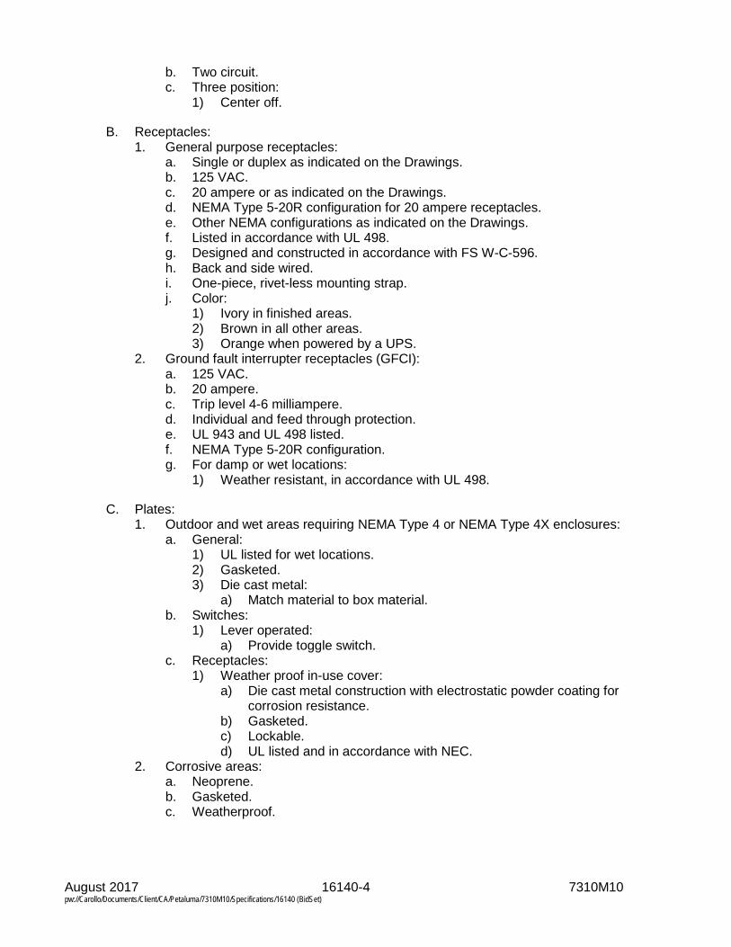
August 2017 16140-4 7310M10 pw://Carollo/Documents/Client/CA/Petaluma/7310M10/Specifications/16140 (BidSet)
b. Two circuit. c. Three position:
1) Center off.
B. Receptacles: 1. General purpose receptacles:
a. Single or duplex as indicated on the Drawings. b. 125 VAC. c. 20 ampere or as indicated on the Drawings. d. NEMA Type 5-20R configuration for 20 ampere receptacles. e. Other NEMA configurations as indicated on the Drawings. f. Listed in accordance with UL 498. g. Designed and constructed in accordance with FS W-C-596. h. Back and side wired. i. One-piece, rivet-less mounting strap. j. Color:
1) Ivory in finished areas. 2) Brown in all other areas. 3) Orange when powered by a UPS.
2. Ground fault interrupter receptacles (GFCI): a. 125 VAC. b. 20 ampere. c. Trip level 4-6 milliampere. d. Individual and feed through protection. e. UL 943 and UL 498 listed. f. NEMA Type 5-20R configuration. g. For damp or wet locations:
1) Weather resistant, in accordance with UL 498.
C. Plates: 1. Outdoor and wet areas requiring NEMA Type 4 or NEMA Type 4X enclosures:
a. General: 1) UL listed for wet locations. 2) Gasketed. 3) Die cast metal:
a) Match material to box material. b. Switches:
1) Lever operated: a) Provide toggle switch.
c. Receptacles: 1) Weather proof in-use cover:
a) Die cast metal construction with electrostatic powder coating for corrosion resistance.
b) Gasketed. c) Lockable. d) UL listed and in accordance with NEC.
2. Corrosive areas: a. Neoprene. b. Gasketed. c. Weatherproof.

August 2017 16140-5 7310M10 pw://Carollo/Documents/Client/CA/Petaluma/7310M10/Specifications/16140 (BidSet)
2.05 EQUIPMENT (NOT USED)
2.06 COMPONENTS (NOT USED)
2.07 ACCESSORIES (NOT USED)
2.08 MIXES (NOT USED)
2.09 FABRICATION (NOT USED)
2.10 FINISHES (NOT USED)
2.11 SOURCE QUALITY CONTROL (NOT USED)
PART 3 EXECUTION
3.01 EXAMINATION (NOT USED)
3.02 PREPARATION (NOT USED)
3.03 INSTALLATION
A. As specified in Section 16050.
B. Mounting heights: 1. Process and production areas:
a. Switches and receptacles 48 inches from finished floor to top of plate. 2. Offices and finished areas:
a. Switches: 48 inches from finished floor to top of plate. b. Receptacles: 18 inches from finished floor to center of plate.
C. Receptacles: 1. Provide GFCI receptacles as indicated on the Drawings.
a. Provide weather resistant GFCI receptacles in all wet or damp areas. 1) As specified in Section 16050.
2. Mount non-weatherproof receptacles vertically: a. Ground slot down.
3. Mount weatherproof receptacles horizontally: a. Neutral slot up.
4. 3-phase receptacles shall be consistent with respect to phase connection at the receptacle terminals. Correct errors in phasing at the source and not the receptacle.
D. Ensure all plates make a firm seal with wall for recessed mounted devices: 1. Outside edges of plates parallel with building lines.
3.04 ERECTION, INSTALLATION, APPLICATION, CONSTRUCTION (NOT USED)
3.05 REPAIR/RESTORATION (NOT USED)
3.06 REINSTALLATION (NOT USED)

August 2017 16140-6 7310M10 pw://Carollo/Documents/Client/CA/Petaluma/7310M10/Specifications/16140 (BidSet)
3.07 COMMISSIONING
A. As specified in Section 01756.
3.08 FIELD QUALITY CONTROL
A. As specified in Section 16050.
3.09 ADJUSTING (NOT USED)
3.10 CLEANING (NOT USED)
3.11 PROTECTION
A. As specified in Section 16050.
3.12 SCHEDULES (NOT USED)
END OF SECTION

August 2017 16150-1 7310M10 pw://Carollo/Documents/Client/CA/Petaluma/7310M10/Specifications/16150 (BidSet)
SECTION 16150
LOW VOLTAGE WIRE CONNECTIONS
PART 1 GENERAL
1.01 SUMMARY
A. Section includes: 1. Wire connecting devices. 2. Terminations. 3. Splices.
B. Related sections: 1. Section 01330 - Submittal Procedures. 2. Section 01756 - Commissioning. 3. Section 16050 - Common Work Results for Electrical. 4. Section 16123 - 600-Volt or Less Wires and Cables.
1.02 REFERENCES
A. As specified in Section 16050.
B. ASTM International (ASTM): 1. D3005 – Standard Specification for Low-Temperature Resistant Vinyl Chloride
Plastic Pressure-Sensitive Electrical Insulating Tape.
C. CSA International (CSA): 1. C22.2 - No.197-M1983 (R2208) - PVC Insulating Tape.
D. Underwriters Laboratories, Inc. (UL): 1. 510 - Standard for Polyvinyl Chloride, Polyethylene, and Rubber Insulating
Tape.
1.03 DEFINITIONS
A. As specified in Section 16050.
1.04 SYSTEM DESCRIPTION
A. Provide a complete system of wiring connectors, terminators, fittings, etc. for a complete wiring system suitable for the cables and conductors used.
1.05 SUBMITTALS
A. Furnish submittals as specified in Sections 01330 and 16050.
B. Product data: 1. Catalog cut sheets. 2. Installation instructions.

August 2017 16150-2 7310M10 pw://Carollo/Documents/Client/CA/Petaluma/7310M10/Specifications/16150 (BidSet)
1.06 QUALITY ASSURANCE
A. As specified in Section 16050.
B. All materials shall be UL listed.
1.07 DELIVERY, STORAGE, AND HANDLING
A. As specified in Section 16050.
1.08 PROJECT OR SITE CONDITIONS
A. As specified in Section 16050.
1.09 SEQUENCING (NOT USED)
1.10 SCHEDULING (NOT USED)
1.11 WARRANTY
A. As specified in Section 16050.
1.12 SYSTEM START-UP
A. As specified in Section 16050.
1.13 OWNER’S INSTRUCTIONS (NOT USED)
1.14 MAINTENANCE (NOT USED)
PART 2 PRODUCTS
2.01 MANUFACTURERS
A. Manufacturers for each type of technology are specified with the equipment in this Section.
2.02 EXISTING PRODUCTS (NOT USED)
2.03 MATERIALS (NOT USED)
2.04 MANUFACTURED UNITS (NOT USED)
2.05 EQUIPMENT
A. Control connections: 1. Use insulated ring type wire terminators for connections to all screw terminals:
a. With chamfered/funneled terminal barrel entry. b. Deep internal serrations. c. Long barrel design to reduce electrical resistance and increased
insulator-barrel surface area to ensure that the insulator remains in contact with the barrel.

August 2017 16150-3 7310M10 pw://Carollo/Documents/Client/CA/Petaluma/7310M10/Specifications/16150 (BidSet)
d. Electroplated-tin copper conductor. e. Manufacturer: The following or equal:
1) Thomas and Betts, Stakon. 2. For process equipment connections work from manufacturer's drawings.
B. Joints, splices, taps, and connections: 1. 600-volt conductors:
a. Use solderless connectors. b. Use only plated copper alloy connectors or lugs:
1) Aluminum connectors or lugs are not acceptable for copper conductors.
c. Under those specific conditions where aluminum conductors have been allowed or are specified then the connectors for aluminum conductors shall be specifically designed for that purpose.
d. For wire Number 10 AWG and smaller use compression splice caps, with insulating caps: 1) Manufacturer: The following or equal:
a) Buchanan 2006S or 2011S, with 2007 or 2014 insulating caps. e. For wire Number 8 AWG and larger, use heavy duty copper compression
connectors: 1) Manufacturer: One of the following or equal:
a) Burndy. b) Thomas and Betts.
f. Heat shrink tubing: 1) Suitable for indoors, outdoors, overhead, direct burial or submerged
applications. 2) Minimum shrink ratio: 4 to 1. 3) Continuous operating temperature: -55 degrees Celsius to
110 degrees Celsius. 4) Internally applied adhesive sealant. 5) Cross-linked polyolefin:
a) Manufacturers, one of the following or equal: (1) 3M ITCSN. (2) Thomas & Betts Shrink-Kon.
2. Instrumentation class cable splices: a. Suitable for indoor, outdoors, weather exposed, direct buried, or
submersed applications. b. Utilizing an epoxy, polyurethane, and re-enterable compounds. c. For use with shielded or unshielded plastic- and rubber-jacketed, signal,
control, and power cables rated up to 1 kilovolt. d. Two-part mold body with tongue and groove seams and built in spacer
webbing. e. Manufacturer: The following or equal:
1) 3M - Scotchcast 72-N.
C. Insulating tape: 1. General purpose insulating tape:
a. Minimum 7 mil vinyl tape. b. Suitable for application in an ambient of -18 degrees Celsius
(0 degrees Fahrenheit). c. Operating range up to 105 degrees Celsius (220 degrees Fahrenheit). d. Flame retardant, hot- and cold- weather resistant, UV resistant.
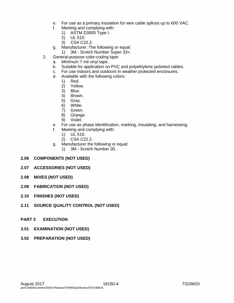
August 2017 16150-4 7310M10 pw://Carollo/Documents/Client/CA/Petaluma/7310M10/Specifications/16150 (BidSet)
e. For use as a primary insulation for wire cable splices up to 600 VAC. f. Meeting and complying with:
1) ASTM D3005 Type I. 2) UL 510. 3) CSA C22.2.
g. Manufacturer: The following or equal: 1) 3M - Scotch Number Super 33+.
2. General-purpose color-coding tape: a. Minimum 7 mil vinyl tape. b. Suitable for application on PVC and polyethylene jacketed cables. c. For use indoors and outdoors in weather protected enclosures. d. Available with the following colors:
1) Red. 2) Yellow. 3) Blue. 4) Brown. 5) Gray. 6) White. 7) Green. 8) Orange. 9) Violet.
e. For use as phase identification, marking, insulating, and harnessing. f. Meeting and complying with:
1) UL 510. 2) CSA C22.2.
g. Manufacturer the following or equal: 1) 3M - Scotch Number 35.
2.06 COMPONENTS (NOT USED)
2.07 ACCESSORIES (NOT USED)
2.08 MIXES (NOT USED)
2.09 FABRICATION (NOT USED)
2.10 FINISHES (NOT USED)
2.11 SOURCE QUALITY CONTROL (NOT USED)
PART 3 EXECUTION
3.01 EXAMINATION (NOT USED)
3.02 PREPARATION (NOT USED)

August 2017 16150-5 7310M10 pw://Carollo/Documents/Client/CA/Petaluma/7310M10/Specifications/16150 (BidSet)
3.03 INSTALLATION
A. As specified in Section 16050.
B. Load connections: 1. Connect loads to the circuits as indicated. Color-code all branch circuits as
specified in Section 16123.
C. Zero to 600-volt systems: 1. Make all connections with the proper tool and die as specified by the device
manufacturer. 2. Use only tooling and dies manufactured by the device manufacturer. 3. Insulate all connections and splices with Scotch 33+ tape and Scotchfill, or
pre-molded plastic covers, or heat shrink tubing and caps. 4. Number all power and control wires before termination.
D. Motor connections (600 volts and below): 1. Terminate all leads and wires with compression type ring lugs. 2. Terminations on all motor leads, including leads that are connected together to
accommodate the motor voltage, and the machine wires entering the motor terminal box from the power source, shall have ring type compression lugs.
3. Cover bolted connectors with a heat shrinkable, cross-linked polyolefin material formed as a single opening boot: a. In damp and wet locations, use a complete kit containing mastic that shall
seal out moisture and contamination. b. Shrink cap with low heat as recommended by manufacturer.
4. Wire markers shall be readable after boot installation. 5. Manufacturer: The following or equal:
a. Raychem MCK.
3.04 ERECTION, INSTALLATION, APPLICATION, CONSTRUCTION (NOT USED)
3.05 REPAIR/RESTORATION (NOT USED)
3.06 RE-INSTALLATION (NOT USED)
3.07 COMMISSIONING
A. As specified in Section 01756.
3.08 FIELD QUALITY CONTROL
A. As specified in Section 16050.
3.09 ADJUSTING (NOT USED)
3.10 CLEANING (NOT USED)

August 2017 16150-6 7310M10 pw://Carollo/Documents/Client/CA/Petaluma/7310M10/Specifications/16150 (BidSet)
3.11 PROTECTION
A. As specified in Section 16050.
3.12 SCHEDULES (NOT USED)
END OF SECTION

August 2017 16222-1 7310M10 pw://Carollo/Documents/Client/CA/Petaluma/7310M10/Specifications/16222 (BidSet)
SECTION 16222
LOW VOLTAGE MOTORS UP TO 500 HORSEPOWER
PART 1 GENERAL
1.01 SUMMARY
A. Section includes: 1. Low voltage motors up to 500 horsepower.
B. Related sections: 1. Section 01330 - Submittal Procedures. 2. Section 01756 - Commissioning. 3. Section 16050 - Common Work Results for Electrical. 4. Section 16950 - Field Electrical Acceptance Tests.
1.02 REFERENCES
A. As specified in Section 16050.
B. American Bearing Manufacturers Association (ABMA): 1. 9 - Load Ratings and Fatigue Life for Ball Bearings. 2. 11 - Load Ratings and Fatigue Life for Roller Bearings.
C. American Petroleum Institute (API): 1. 670 - Vibration, Axial Position, and Bearing Temperature Monitoring Systems.
D. ASTM International (ASTM). 1. B117 - Standard Practice for Operating Salt Spray (Fog) Apparatus.
E. Institute of Electrical and Electronic Engineers (IEEE): 1. 43 - IEEE Recommended Practice for Testing Insulation Resistance of
Rotating Machinery. 2. 112 - IEEE Standard Test Procedure for Polyphase Induction Motors and
Generators. 3. 114 - Standard Test Procedure for Single-Phase Induction Motors. 4. 303 - Recommended Practice for Auxiliary Devices for Rotating Electrical
Machines in Class I, Division 2 and Zone 2 Locations. 5. 841 - Standard for Petroleum and Chemical Industry-Premium-Efficiency,
Severe Duty, Totally Enclosed Fan-Cooled (TEFC) Squirrel Cage Induction Motors - Up to and Including 370 kW (500 hp).
6. 1349 - Guide for Application of Electric Motors in Class I, Division 2 Hazardous (Classified) Locations.
F. National Electrical Manufacturers' Association (NEMA): 1. MG-1 - Motors and Generators. 2. MG-2 - Safety Standard for Construction and Guide for Selection, Installation,
and Use of Electric Motors and Generators.

August 2017 16222-2 7310M10 pw://Carollo/Documents/Client/CA/Petaluma/7310M10/Specifications/16222 (BidSet)
G. Underwriters Laboratories Inc. (UL): 1. 674 - Electric Motors and Generators for Use in Division 1 Hazardous
(Classified) Locations.
1.03 DEFINITIONS
A. As specified in Section 16050.
1.04 SYSTEM DESCRIPTION
A. Furnish and install electric motors and accessories as specified in this Section and the Sections specifying driven equipment to provide a complete and operable installation.
1.05 SUBMITTALS
A. Furnish submittals as specified in Sections 01330 and 16050.
B. Submit completed motor data sheets for each motor supplied: 1. Conform to data sheet in the appendix of this Section. 2. Manufacturer’s or other data sheets are not acceptable.
C. Product data: 1. Descriptive bulletins. 2. Machine tag and loop number as indicated on the Drawings and in the
specification section number of the driven machine. 3. Complete electrical data. 4. Torque, current, and power factor versus speed curves:
a. At 100 percent rated voltage for all full voltage started and VFD-driven motors.
b. For motors on reduced voltage start at 70, 80, 90, and 100 percent rated voltage.
5. Accessories data: a. Power factor correction capacitors:
1) Size in KVAR, for all motors not connected to variable frequency drives.
b. Motor winding heaters: 1) Voltage. 2) Watts.
c. Winding temperature detectors: 1) Type. 2) Rating.
d. Moisture detectors. 6. Mechanical data:
a. Bearing design and bearing life calculations. b. Resonant frequencies for all VFD-driven motors 50 horsepower or
greater.
D. Shop drawings: 1. Motor weight. 2. Frame size. 3. Conduit box(es), size(s), and location(s). 4. Outline drawings with dimensions.

August 2017 16222-3 7310M10 pw://Carollo/Documents/Client/CA/Petaluma/7310M10/Specifications/16222 (BidSet)
5. Installation details for the project seismic criteria.
E. Test reports: 1. Factory test reports with test reference standard identified.
F. Certification: 1. When motors are driven by variable speed drive systems, submit certification
that selected motor: a. Is capable of satisfactory performance under the intended load. b. Meets the requirements of the latest edition of NEMA MG-1 Part 31.
G. Calculations: 1. Where site conditions specified in Section 16050 exceed manufacturer’s
ratings, provide derating calculations for each motor.
1.06 QUALITY ASSURANCE
A. As specified in Section 16050.
1.07 DELIVERY, STORAGE, AND HANDLING
A. As specified in Section 16050.
B. Motors 200 hp and larger: 1. Rotate shaft 90 degrees once per month.
1.08 PROJECT OR SITE CONDITIONS
A. As specified in Section 16050.
1.09 SEQUENCING (NOT USED)
1.10 SCHEDULING (NOT USED)
1.11 WARRANTY
A. As specified in Section 16050.
1.12 SYSTEM START-UP
A. As specified in Section 16050.
1.13 OWNER’S INSTRUCTION (NOT USED)
1.14 MAINTENANCE (NOT USED)
PART 2 PRODUCTS
2.01 MANUFACTURERS
A. One of the following or equal: 1. US Motors.

August 2017 16222-4 7310M10 pw://Carollo/Documents/Client/CA/Petaluma/7310M10/Specifications/16222 (BidSet)
2. General Electric. 3. Reliance. 4. Toshiba. 5. Baldor.
2.02 EXISTING PRODUCTS (NOT USED)
2.03 MATERIALS (NOT USED)
2.04 MANUFACTURED UNITS (NOT USED)
2.05 EQUIPMENT
A. 3-phase induction motors - general: 1. Voltage:
a. All motors 1/2 hp and larger shall be rated 460 V, 3-phase unless otherwise indicated on the Drawings.
b. Dual voltage motors rated 230/460 V, 3-phase are acceptable provided all leads are brought to the conduit box.
2. Motors driving identical machines shall be identical. 3. All motors greater than 1 hp and up to 500 hp shall meet the "NEMA Premium
Efficiency" percent listed in NEMA MG-1. 4. Horsepower as indicated on the Drawings:
a. Horsepower ratings indicated on the Drawings are based on vendor’s estimates. Provide motors sized for the load of the actual equipment furnished without operating in the service factor.
5. Service factor: a. 1.15 service factor on sine wave power. b. 1.0 when driven by VFD.
6. Torque: a. Provide motors that develop sufficient torque for acceleration to full speed
at voltage 10 percent less than motor nameplate rating. b. When started using reduced voltage starters:
1) Provide motors that develop sufficient torque for acceleration to full speed.
c. NEMA Design B except where driven load characteristics require other than normal starting torque: 1) In no case shall starting torque or breakdown torque be less than the
values specified in NEMA MG-1. 7. Enclosures:
a. As specified in the individual equipment Specifications or in this Section. b. Totally enclosed fan cooled:
1) Cast iron conduit box. 2) Tapped drain holes with Type 316 stainless steel plugs for frames
286 and smaller, and automatic breather and drain devices for frames 324 and larger.
c. Lifting devices: All motors weighing 265 pounds (120 kilograms) or more shall have suitable lifting devices for installation and removal.
8. Manufactured with cast iron frames in accordance with NEMA MG-1 or manufacturer’s standard material for the specified rating.

August 2017 16222-5 7310M10 pw://Carollo/Documents/Client/CA/Petaluma/7310M10/Specifications/16222 (BidSet)
9. Nameplates: a. Provide all motors with a permanent, stainless steel nameplate indelibly
stamped or engraved with: 1) NEMA standard motor data.
a) Indicate compliance with NEMA MG-1 Part 31 for inverter duty motors.
2) AFBMA bearing numbers and lubrication instructions. 10. Hardware:
a. Type 316 stainless steel. 11. Conduit boxes:
a. Cast iron or stamped steel. b. Split from top to bottom. c. Provide gaskets at the following interfaces:
1) Frames and conduit boxes. 2) Conduit boxes and box covers.
d. Rotatable through 360 degrees in 90-degree increments. 1) Where available based on the size of the conduit box.
e. Exceeding the dimensions defined in NEMA MG-1. f. Provide grounding lugs inside conduit boxes for motor frame grounding.
12. Motor bearings: a. Antifriction. b. Regreasable and initially filled with grease for horizontal motors and
vertical motors per manufacturer’s standard design. c. Bearings and lubrication suitable for ambient temperature and
temperature rise. d. Suitable for intended application and have ABMA L-10 rating life of
60,000 hours or more. e. Fit bearings with easily accessible grease supply, flush, drain, and relief
fittings using extension tubes where necessary. f. Where specified in the equipment Specifications, provide split-sleeve type
hydrodynamic radial bearings. Provide a bearing isolator to protect bearings from contaminants.
13. Insulation systems: a. Motors installed in ambient temperatures 40 degrees Celsius or less:
1) Provide Class F insulation. 2) Design temperature rise consistent with Class B insulation. 3) Rated to operate at an ambient temperature of 40 degrees Celsius at
the altitude where the motor will be installed. 14. Motor leads:
a. Insulated leads with non-wicking, non-hydroscopic material. Class F insulation.
15. Noise: a. Maximum operating noise level in accordance with NEMA MG-1.
16. Motor protection: a. Provide temperature detection in motor windings. b. Provide moisture detection in motor housing. c. Other detection and protection functions specified in the in the driven
equipment Section.
B. Motors driven by variable frequency drives: 1. Compatible with the variable frequency drives specified. 2. Inverter duty rated and labeled.

August 2017 16222-6 7310M10 pw://Carollo/Documents/Client/CA/Petaluma/7310M10/Specifications/16222 (BidSet)
3. Meet the requirements of NEMA MG-1 Part 31. 4. Winding insulation meets the requirements of NEMA MG-1 Part 31.4.4.2. 5. Capable of running continuously at 1/10th of full speed, with no harmful effects
or overheating. 6. Shaft grounding ring:
a. Provide a shaft grounding ring for each VFD-driven motor. b. Aluminum frame and internal components. c. Conductive microfiber brushes. d. Maintenance free design. e. Aegis Bearing Protection ring as manufactured by Electro Static
Technology or equal. 7. On motors over 100 HP, provide insulated bearings on bearings on both ends
of the motor or on the end opposite of the shaft ground ring as recommended by the motor manufacturer.
C. Single-phase motors: 1. Capacitor start type rated for operation at 115 volts, 60 hertz, unless otherwise
specified or as indicated on the Drawings. 2. Totally enclosed fan cooled (TEFC) motors manufactured in accordance with
NEMA MG 1. 3. Ball bearings: Sealed. 4. 1/2 horsepower or less fan motors:
a. Split-phase or shaded pole type when standard for the equipment. b. Open type when suitably protected from moisture, dripping water, and lint
accumulation. 5. Wound rotor or commutator type single-phase motors only when their specific
characteristics are necessary for application and their use is acceptable to the Engineer.
6. Integral overload protection.
2.06 COMPONENTS (NOT USED)
2.07 ACCESSORIES
A. Motor winding heaters: 1. Provide all 3-phase motors with belted or cartridge space heaters mounted
within the motor enclosure. 2. Space heater rating shall be 120 volts, single-phase, unless otherwise
indicated on the Drawings. 3. Power leads for heaters wired into conduit box. 4. Installed within motor enclosure adjacent to core iron.
B. Winding temperature detectors: 1. Provide factory installed winding temperature detector with leads terminating in
the conduit box: Where required by the driven equipment Specification or as indicated on the Drawings.
2. Temperature switches with normally closed contacts as indicated on the Drawings.
2.08 MIXES (NOT USED)
2.09 FABRICATION (NOT USED)

August 2017 16222-7 7310M10 pw://Carollo/Documents/Client/CA/Petaluma/7310M10/Specifications/16222 (BidSet)
2.10 FINISHES (NOT USED)
2.11 SOURCE QUALITY CONTROL (NOT USED)
PART 3 EXECUTION
3.01 EXAMINATION (NOT USED)
3.02 PREPARATION (NOT USED)
3.03 INSTALLATION
A. As specified in Section 16050.
B. Install motors in accordance with manufacturer's instructions.
C. Install shaft grounding ring on VFD-driven motors in accordance with the manufacturer’s instructions.
3.04 ERECTION, INSTALLATION, APPLICATION, CONSTRUCTION (NOT USED)
3.05 REPAIR/RESTORATION (NOT USED)
3.06 RE-INSTALLATION (NOT USED)
3.07 COMMISSIONING AND PROCESS START-UP
A. As specified in Section 01756.
B. Factory testing: 1. Motors less than 250 horsepower:
a. Perform manufacturer’s standard production tests including but not limited to: 1) No load current. 2) High potential test. 3) Winding resistance.
b. Furnish copies of standard test reports on prototype or identical units.
3.08 FIELD QUALITY CONTROL
A. As specified in Section 16050.
B. Before start-up, perform insulation resistance test on each motor furnished or installed on this project: 1. Windings energized to 1,000 volts DC for 1 minute. 2. Resistance measured at the end of the test, recorded, and submitted to the
Engineer for review. 3. Inform the Engineer of any unusual or unacceptable test results. 4. This test is in addition to the acceptance tests in Section 16950.
3.09 ADJUSTING (NOT USED)

August 2017 16222-8 7310M10 pw://Carollo/Documents/Client/CA/Petaluma/7310M10/Specifications/16222 (BidSet)
3.10 CLEANING (NOT USED)
3.11 PROTECTION
A. As specified in Section 16050.
END OF SECTION

August 2017 16222-9 7310M10 pw://Carollo/Documents/Client/CA/Petaluma/7310M10/Specifications/16222 (BidSet)
MOTOR DATA SHEET
MOTOR/ EQUIPMENT TAG MOTOR NUMBER
SPECIFICATION NUMBER OF DRIVEN MACHINE
MOTOR NAMEPLATE DATA
MANUFACTURER MODEL/SERIES MODEL NO.
FRAME ENCLOSURE NEMA DESIGN
HP SERVICE FACTOR RPM
INSULATION CLASS VOLTS FULL LOAD AMPS
AMBIENT TEMP PHASE NO LOAD AMPS
DESIGN TEMP
HERTZ LOCK ROTOR AMPS
INRUSH CODE LETTER
100% LOAD 75% LOAD 50% LOAD
GUARANTEED MINIMUM EFFICIENCIES:
GUARANTEED MINIMUM POWER FACTOR:
MAXIMUM SIZE OF POWER FACTOR CORRECTION CAPACITOR: KVAR
ACCESSORIES
MOTOR WINDING HEATER VOLTS WATTS
WINDING THERMAL PROTECTION
WINDING TEMP SWITCHES (YES/NO)
RTD:
TYPE QUANTITY PER PHASE # OF WIRES
NOMINAL RESISTANCE NOMINAL TEMP COEFFICIENT
RECOMMENDED ALARM
DEGREES CELSIUS
RECOMMENDED TRIP
DEGREES CELSIUS
SPECIAL APPLICATIONS
INVERTER DUTY* (YES/NO) PART WINDING (YES/NO) WYE - DELTA (YES/NO)
2 SPEED, 1 WINDING (YES/NO) 2 SPEED, 2 WINDING (YES/NO)
AREA CLASSIFICATION:
CLASS DIVISION GROUP TEMP CODE * Conforms to NEMA MG-1 Part 31.


August 2017 16262-1 7310M10 pw://Carollo/Documents/Client/CA/Petaluma/7310M10/Specifications/16262 (BidSet)
SECTION 16262
VARIABLE FREQUENCY DRIVES 0.50 – 50 HORSEPOWER
PART 1 GENERAL
1.01 SUMMARY
A. Section includes: 1. Variable frequency drives (VFD) 0.5 to 50 horsepower for control of NEMA
Design B squirrel cage induction motors.
B. Related sections: 1. Section 01330 - Submittal Procedures. 2. Section 01756 - Commissioning. 3. Section 16050 - Common Work Results for Electrical. 4. Section 16222 - Low Voltage Motors Up To 500 Horsepower.
1.02 REFERENCES
A. As specified in Section 16050.
B. International Organization for Standardization (ISO): 1. 9001 - Quality Management Systems - Requirements.
C. National Electrical Manufacturers Association (NEMA): 1. MGI, Part 31 – Motors with higher peak voltage capability.
D. Underwriters’ Laboratories (UL): 1. 508A - Standard for Safety for Industrial Control Panels. 2. 508C - Standard for Power Conversion Equipment.
1.03 DEFINITIONS
A. As specified in Section 16050.
B. Specific definitions: 1. Point of common coupling: the point of common coupling for all harmonic
calculation and field measurements for both voltage and current distortions is defined as the closest directly connected bus supplying power to the VFD.
1.04 SYSTEM DESCRIPTION
A. Design requirements: 1. Each VFD system consists of all components required to meet the
performance, protection, safety, testing, and certification criteria of this Section.
2. The VFD system: a. Is a fully integrated package. b. Includes all material necessary to interconnect all VFD system elements,
even if shipped separately.

August 2017 16262-2 7310M10 pw://Carollo/Documents/Client/CA/Petaluma/7310M10/Specifications/16262 (BidSet)
3. Coordinate bearing protection methods with the supplier of the driven equipment.
B. Any modifications to a standard product necessary to meet this Section shall be made only by the VFD manufacturer: 1. Each VFD shall be completely factory pre-wired, assembled, and then tested
as a complete system by the VFD manufacturer to ensure a properly coordinated, fully integrated drive system.
2. The VFD shall be capable of operating standard NEMA Design B motors. It is the responsibility of the VFD manufacturer to ensure that the drive will not damage motor insulation due to high carrier frequency, reflected wave, dv/dt or other drive electrical characteristics based upon the installed conditions: a. Provide equipment necessary to mitigate potential damage to motor
insulation. b. Motors as specified in Section 16222.
C. Performance: 1. Operating envelope:
a. Speed and torque requirements: 1) Provide a variable torque or constant torque VFD as required by the
driven load. 2) The VFD shall be capable of producing a variable alternating
voltage/frequency output to provide continuous operation over the 40 to 200 percent (25 to 120 hertz) speed range.
b. Current requirements: 1) Full rated current output on a continuous basis. 2) Variable torque VFD:
a) Minimum 110 percent current overload for 1 minute. 3) Constant torque VFD:
a) Minimum 150 percent current overload for 1 minute. 2. Minimum VFD system efficiency:
a. Ninety-six percent when operating at the rated kW output. b. VFD system efficiency shall be calculated as follows:
100 x (Supply)Power
(Load)Power = (%)Efficiency
Power (Load) is the total power measured at the output terminals of the drive system, including VFD, output filters or transformers. Power (Supply) is the total power measured at the input terminals of the VFD including input filters, line reactors, isolation transformers, harmonic distortion attenuation equipment and auxiliary equipment (e.g., controls, fans) for complete system operation.
3. Total power factor: a. Minimum of 0.96 lagging across the entire speed range. b. At no speed shall the VFD have a leading power factor.
4. Frequency accuracy: a. Minimum of within 0.01 percent.
5. Speed regulation: a. Minimum of within 0.5 percent across the entire speed range.

August 2017 16262-3 7310M10 pw://Carollo/Documents/Client/CA/Petaluma/7310M10/Specifications/16262 (BidSet)
1.05 SUBMITTALS
A. Furnish submittals as specified in Sections 01330 and 16050: 1. Custom prepared by the VFD manufacturer and specific for the equipment
furnished.
B. Product data: 1. Manufacturer of the VFD. 2. Manufacturer of all components of the VFD. 3. Dimensions:
a. Height. b. Width. c. Depth. d. Weight.
4. Nameplate schedule. 5. Bill of material. 6. Ratings:
a. Voltage. b. Phase. c. Input current. d. Output current. e. Interrupting rating. f. Momentary current rating.
7. List of recommended spare parts. 8. Catalog cut sheets for major components. 9. Design data:
a. Efficiency and power factor values. b. Certification that the drive is sized for the full nameplate motor
horsepower and current of the driven load at the installed altitude and ambient temperature.
c. Certification that based upon VFD design, cable length to motor, and motor dielectric insulation level that the VFD will not damage motor insulation due to carrier frequency, reflected wave, dv/dt, or other VFD produced characteristics.
d. Certification that all electronic circuits and printed circuit boards are conformally coated.
10. For equipment installed in structures designated as seismic design category C, D, E, or F submit the following as specified in Section 16050: a. Manufacturer’s statement of seismic qualification with substantiating test
data. b. Manufacturer’s special seismic certification with substantiating test data.
C. Shop drawings: 1. Complete plan and elevation drawings showing:
a. All dimensions. b. Panel, sub-panel and component layout indexed to the bill of material. c. Conduit connections.
2. Block diagram showing the basic control and protection systems specifying the protection, control, trip and alarm functions, the reference signals and commands and the auxiliary devices.

August 2017 16262-4 7310M10 pw://Carollo/Documents/Client/CA/Petaluma/7310M10/Specifications/16262 (BidSet)
3. Complete schematic, wiring and interconnection diagrams showing connections to both internal and external devices: a. Include terminal number and wire numbers.
4. Complete single-line and 3-line diagrams including, but not limited to, circuit breakers, motor circuit protectors, contactors, instrument transformers, meters, relays, timers, control devices, and other equipment comprising the complete system: a. Clearly indicate device electrical ratings on the drawings.
D. Installation instructions: 1. Detail the complete installation of the equipment including rigging, moving, and
setting into place. 2. For equipment installed in structures designated as seismic design category C,
D, E, or F: a. Provide project-specific installation instructions and anchoring details
based on support conditions and requirements to resist seismic and wind loads as specified in Section 16050.
b. Submit anchoring drawings with supporting calculations. c. Drawings and calculations shall be stamped by a professional engineer
registered in the state where the Project is being constructed.
E. Operation and maintenance manuals: 1. Spare parts list with supplier names and part numbers. 2. Startup and commissioning instructions and data. 3. Operating manuals:
a. Submit operating instructions and a maintenance manual presenting full details for care and maintenance of each model of VFD provided under this Contract.
4. Operating instructions: a. Written descriptions detailing the operational functions of all controls on
the front panel. 5. Maintenance manual:
a. Furnish maintenance manuals with instructions covering all details pertaining to care and maintenance of all equipment as well as identifying all parts.
b. Manuals shall include, but are not limited to the following: 1) Adjustment and test instructions covering the steps involved in the
initial test, adjustment and start-up procedures. 2) Detailed control instructions which outline the purpose and operation
of every control device used in normal operation. 3) All schematic wiring and external diagrams:
a) Furnish drawings in a reduced 11-inch by 17-inch format that are fully legible at that size.
F. Test forms and reports. 1. Submit complete factory acceptance test procedures and all forms used during
the test.
G. Manufacturer’s Certificate of Installation and Functionality Compliance.

August 2017 16262-5 7310M10 pw://Carollo/Documents/Client/CA/Petaluma/7310M10/Specifications/16262 (BidSet)
H. Manufacturer’s field reports: 1. Report listing the setting of all VFD adjustable parameters and their values
after start-up.
I. Record Documents: 1. Certified Record Documents of equipment with information listed above.
1.06 QUALITY ASSURANCE
A. As specified in Section 16050.
B. Qualifications: 1. Any third party certification, safety or protection requirements shall be applied
to the VFD system as a whole. Certification or protection of system elements or individual components by themselves is not acceptable.
2. VFDs shall be UL 508C listed and labeled: a. UL 508C for individual units. b. UL 508A for VFD systems in control panels.
3. Variable frequency drives shall be manufactured by the VFD manufacturer at its own facility which shall have a quality assurance program that is certified in conformance with ISO 9001.
1.07 DELIVERY, STORAGE, AND HANDLING
A. As specified in Section 16050.
B. Ship the VFDs and associated equipment to the job site on a dedicated air ride vehicle that will allow the Contractor to utilize on site off loading equipment: 1. VFDs shall be delivered to the site preassembled and wired.
C. Furnish temporary equipment heaters within the VFD to prevent condensation from forming.
1.08 PROJECT OR SITE CONDITIONS
A. As specified in Section 16050.
1.09 SEQUENCING
A. Conduct factory acceptance test and submit certified test results for Engineer’s review.
B. Ship equipment to project site after successful completion of factory acceptance test.
C. Assemble equipment in the field.
D. Conduct field acceptance test and submit results for Engineer’s review.
E. Submit Manufacturer’s of Installation and Functionality Compliance
F. Conduct Owner’s training sessions.

August 2017 16262-6 7310M10 pw://Carollo/Documents/Client/CA/Petaluma/7310M10/Specifications/16262 (BidSet)
G. Commissioning and process start-up as specified in Section 01756.
1.10 SCHEDULING
A. As specified in Section 16050.
1.11 WARRANTY
A. As specified in Section 16050.
1.12 SYSTEM START-UP
A. As specified in Section 16050.
B. The VFD manufacturer shall be responsible for startup of the VFDs in the presence of the equipment suppliers, Contractor, Engineer and Owner.
1.13 OWNERS INSTRUCTIONS (NOT USED)
1.14 MAINTENANCE
A. Spare parts: 1. The following spare parts shall be furnished:
a. One complete VFD of each size furnished. b. Any special dedicated tools for emergency service and troubleshooting. c. All hardware and software required for configuration, maintenance,
troubleshooting and inquiry of all drive parameters.
PART 2 PRODUCTS
2.01 MANUFACTURERS
A. One of the following or equal: 1. Eaton/Cutler-Hammer. 2. Allen-Bradley. 3. Schneider Electric/Square D. 4. General Electric. 5. ABB.
2.02 EXISTING PRODUCTS (NOT USED)
2.03 MATERIALS (NOT USED)
2.04 MANUFACTURED UNITS (NOT USED)
2.05 EQUIPMENT
A. General: 1. Sinusoidal pulse width modulated (PWM) type drive.
a. Six-pulse insulated gate bipolar transistor (IGBT) power section. b. Microprocessor based controls. c. Line and load reactors.

August 2017 16262-7 7310M10 pw://Carollo/Documents/Client/CA/Petaluma/7310M10/Specifications/16262 (BidSet)
B. Ratings: 1. Voltage:
a. Input voltage as indicated on the Drawings.
C. Operational features: 1. Protective features:
a. Provide the following minimum protective features: 1) Motor overload protection. 2) Instantaneous overcurrent. 3) Instantaneous overvoltage. 4) Undervoltage. 5) Power unit overtemperature. 6) Phase loss. 7) VFD output short circuit.
2. Control mode: a. Operation in either a constant volts/hertz or sensorless vector mode:
1) The control mode selectable using the programming keypad. 3. Frequency control:
a. Minimum of 3 selectable skip frequencies with adjustable bandwidths. b. Programmable minimum frequency. c. Programmable maximum frequency.
4. Acceleration/deceleration: a. Separately adjustable acceleration and deceleration rates:
1) Each rate adjustable from 0.01 to 1,800 seconds. 5. Spinning load:
a. The VFD shall be capable of determining the speed and direction of a spinning load, “catch” the load and accelerate or decelerate it without damage to the load.
6. Programmable loss of signal: a. Upon loss of speed reference the VFD shall be programmable to either:
1) Stop. 2) Maintain current speed. 3) Default to pre-selected speed.
7. Power interrupt ride-through: a. The VFD shall be capable of continuous operation in the event of a power
loss of 5 cycles or less. 8. Inputs/Outputs:
a. Manufacturer’s standard number the following: 1) Analog inputs:
a) Configurable as either 0 to 10 volts or 4 to 20 milliamperes. 2) Analog outputs:
a) Programmable 4 to 20 milliamperes isolated. 3) Discrete inputs:
a) Programmable. 4) Discrete outputs:
a) Programmable. b) Form C relay contacts.
5) Potentiometer 3-wire input. b. Provide additional inputs/outputs as required to meet the control functions
indicated on the Drawings.

August 2017 16262-8 7310M10 pw://Carollo/Documents/Client/CA/Petaluma/7310M10/Specifications/16262 (BidSet)
9. Diagnostics: a. Store a minimum of 4 fault conditions in non-volatile memory on a first in-
first out basis. b. Operational parameters stored at the time of a the fault:
1) Operating frequency. 2) Drive status. 3) Power mode.
c. Fault memory accessible via RS-232, RS-422 or RS-485. 10. Automatic restart:
a. User selectable automatic restart feature allowing the VFD to restart following a momentary power failure or other VFD fault: 1) Programmable for up to 9 restart attempts. 2) Adjustable time delay between restart attempts.
2.06 COMPONENTS
A. Enclosure: 1. NEMA Type 12. 2. Provide cooling devices required to maintain the VFD within the
manufacturer’s specified temperature limits for the Project conditions: a. Provide cooling device failure alarm.
B. Power disconnect: 1. Flange mounted motor circuit protector, MCP. 2. Lockable in the OFF position.
C. Reactors: 1. Line reactors: 3 percent input and 3 percent output.
D. Keypad: 1. Provide each VFD with a keypad for programming and control. 2. Keypad requirements:
a. Password security to protect drive parameters. b. Mounted on the door of the VFD. c. Back-lit LCD:
1) Minimum of 2 lines with a minimum of 16 characters per line. d. Programming and display features language: English. e. Capable of displaying the following parameters:
1) Speed (percent). 2) Output current (amperes). 3) Output frequency (hertz). 4) Input voltage. 5) Output voltage. 6) Total 3-phase kilowatt. 7) Kilowatt-hour meter. 8) Elapsed run time meter. 9) Revolutions per minute. 10) Direct current bus voltage.
3. In addition to all keys required for programming, provide the following controls on the keypad: a. Auto/manual selector. b. Start pushbutton.

August 2017 16262-9 7310M10 pw://Carollo/Documents/Client/CA/Petaluma/7310M10/Specifications/16262 (BidSet)
c. Stop pushbutton. d. Jog pushbutton. e. Speed increment. f. Speed decrement. g. Forward/reverse selector. h. Run LED indicator. i. Program LED indicator. j. Fault LED indicator.
4. Provide the VFD with the hardwired controls as indicated on the Drawings.
E. Control power transformer: 1. Furnish a control power transformer mounted and wired inside the VFD
enclosure. 2. With primary and secondary fusing. 3. Sized to power all VFD controls and options as well as any external devices
indicated on the Drawings including the motor winding heater.
2.07 ACCESSORIES
A. Metal oxide varistors: 1. Provide protection for the VFD against:
a. Line transients: 5,000 volt peak minimum. b. Line to ground transients: 7,000 peak minimum.
B. Conformal coating: 1. Provide conformal coating material applied to electronic circuitry and printed
circuit boards to act as a protection against moisture, dust, temperature extremes, and chemicals such as H2S and chlorine.
2.08 MIXES (NOT USED)
2.09 FABRICATION (NOT USED)
2.10 FINISHES A. Enclosure finish shall be manufacturer’s standard gray.
2.11 SOURCE QUALITY CONTROL (NOT USED)
PART 3 EXECUTION
3.01 EXAMINATION (NOT USED)
3.02 PREPARATION (NOT USED)
3.03 INSTALLATION
A. As specified in Section 16050.
B. Install the equipment in accordance with the accepted installation instructions and anchorage details to meet the seismic and wind load requirements at the Project site.

August 2017 16262-10 7310M10 pw://Carollo/Documents/Client/CA/Petaluma/7310M10/Specifications/16262 (BidSet)
C. General: 1. Furnish all cables, conduit, lugs, bolts, expansion anchors, sealants, and other
accessories needed to complete the installation of the VFD (free-standing or within motor control center).
2. Assemble and install the VFD in the locations and with the layouts indicated on the Drawings.
3. Perform work in accordance with manufacturer’s instructions and shop drawings.
4. Furnish components and equipment as required to complete the installation. 5. Replace any hardware lost or damaged during the installation or handling to
provide a complete installation. a.
6. Provide openings in top or bottom of the VFD (free-standing or within motor control center) enclosure for conduit only, no additional openings will be allowed: a. Improperly cut holes will require that the entire panel be replaced:
1) No hole closers or patches will be allowed. 7. Bundle circuits together and terminate in each unit:
a. Tie with nylon wire ties. b. Label all wires at each end with wire numbers shown on the approved
control drawings. c. All connections to and from the VFD (free-standing or within motor control
center) enclosure must be made via terminal blocks.
3.04 ERECTION, INSTALLATION, APPLICATION, CONSTRUCTION (NOT USED)
3.05 REPAIR/RESTORATION (NOT USED)
3.06 RE-INSTALLATION (NOT USED)
3.07 COMMISSIONING
A. As specified in Section 01756.
B. Source testing (Factory Acceptance Tests): 1. General:
a. Incoming inspection of components and raw materials based on strategic supplier base and experience.
b. All VFDs furnished under this Section shall be tested and inspected as specified below. Testing of VFDs based on sampling plans is not allowed.
c. The testing procedures specified are the minimum acceptable requirements. The manufacturer may perform additional tests at its discretion.
2. Failure of any component during testing requires repair of the faulted component and complete retest.
3. Tests: a. Perform manufacturer's standard factory acceptance tests.
C. Provide Manufacturer’s Certificate of Installation and Functionality Compliance as specified in Section 01756.
D. Owner training: 1. As specified in Sections 01756 and 16050.

August 2017 16262-11 7310M10 pw://Carollo/Documents/Client/CA/Petaluma/7310M10/Specifications/16262 (BidSet)
3.08 FIELD QUALITY CONTROL
A. As specified in Section 16050.
B. Provide the services of a VFD manufacturer representative for startup assistance and training: 1. Inspection and field adjustment:
a. Supervise the following and submit written certification that the equipment and controls have been properly installed, aligned, adjusted, and readied for operation.
2. Startup field testing: a. Provide technical direction for testing, checkout, and startup of the VFD
equipment in the field. b. Under no circumstances are any portions of the drive system to be
energized without authorization from the manufacturer's representative.
3.09 ADJUSTING
A. Make all adjustments as necessary and recommended by the manufacturer, Engineer, or testing firm.
B. Provide the services of a VFD manufacturer factory technician to make all drive parameters and protective device settings: 1. Protective device settings provided by the VFD manufacturer in accordance
with the manufacturer of the driven equipment requirements. 2. Provide documentation of VFD settings included but not limited to:
a. Minimum speed. b. Maximum speed. c. Skip speeds. d. Current limit. e. Acceleration time. f. Deceleration time.
3.10 CLEANING
A. As specified in Section 16050.
3.11 PROTECTION
A. As specified in Section 16050.
3.12 SCHEDULES (NOT USED)
END OF SECTION


August 2017 16412-1 7310M10 pw://Carollo/Documents/Client/CA/Petaluma/7310M10/Specifications/16412 (BidSet)
SECTION 16412
LOW VOLTAGE MOLDED CASE CIRCUIT BREAKERS
PART 1 GENERAL
1.01 SUMMARY
A. Section includes: 1. Low voltage molded case circuit breakers.
B. Related sections: 1. Section 01330 - Submittal Procedures. 2. Section 01756 - Commissioning. 3. Section 16050 - Common Work Results for Electrical.
1.02 REFERENCES
A. As specified in Section 16050.
B. National Electrical Manufacturers Association (NEMA): 1. AB 3. - Molded Case Circuit Breakers and Their Application.
C. Underwriter’s Laboratories (UL): 1. 489 - Molded-Case Circuit Breakers, Molded-Case Switches, and Circuit-
Breaker Enclosures. 2. 943 - Ground Fault Circuit Interrupters.
1.03 DEFINITIONS
A. As specified in Section 16050.
B. In accordance with UL 489.
1.04 SYSTEM DESCRIPTION
A. Molded case thermal magnetic or motor circuit protector type circuit breakers as indicated on the Drawings and connected to form a completed system.
1.05 SUBMITTALS
A. Furnish submittals as specified in Sections 01330 and 16050.
B. Product data: 1. Catalog cut sheets. 2. Manufacturer’s time-current curves for all molded case circuit breakers
furnished.
1.06 QUALITY ASSURANCE
A. As specified in Section 16050.

August 2017 16412-2 7310M10 pw://Carollo/Documents/Client/CA/Petaluma/7310M10/Specifications/16412 (BidSet)
B. Low voltage molded case circuit breakers shall be UL listed and labeled.
1.07 DELIVERY, STORAGE AND HANDLING
A. As specified in Section 16050.
1.08 PROJECT OR SITE CONDITIONS
A. As specified in Section 16050.
1.09 SEQUENCING (NOT USED)
1.10 SCHEDULING (NOT USED)
1.11 WARRANTY
A. As specified in Section 16050.
1.12 SYSTEM START-UP
A. As specified in Section 16050.
1.13 OWNER’S INSTRUCTIONS (NOT USED)
1.14 MAINTENANCE (NOT USED)
PART 2 PRODUCTS
2.01 MANUFACTURERS
A. One of the following or equal: 1. Eaton/Cutler-Hammer. 2. General Electric Company. 3. Schneider Electric/Square D Company. 4. ABB.
2.02 EXISTING PRODUCTS (NOT USED)
2.03 MATERIALS (NOT USED)
2.04 MANUFACTURED UNITS
A. General: 1. Conforming to UL 489. 2. Operating mechanism:
a. Quick-make, quick-break, non-welding silver alloy contacts. b. Common Trip, Open and Close for multi-pole breakers such that all poles
open and close simultaneously. c. Mechanically trip free from the handle. d. Trip indicating handle - automatically assumes a position midway between
the manual ON and OFF positions to clearly indicate the circuit breaker has tripped.

August 2017 16412-3 7310M10 pw://Carollo/Documents/Client/CA/Petaluma/7310M10/Specifications/16412 (BidSet)
e. Lockable in the "OFF" position. 3. Arc extinction:
a. In arc chutes. 4. Voltage and current ratings:
a. Minimum ratings as indicated on the Drawings. b. Minimum frame size 100A.
5. Interrupting ratings: a. Minimum ratings as indicated on the Drawings. b. Not less than the rating of the assembly (panelboard, switchboard, motor
control center, etc.)
B. Motor circuit protectors: 1. Instantaneous only circuit breaker as part of a listed combination motor
controller. 2. Each pole continuously adjustable in a linear scale with ‘LO’ and ‘HI’ settings
factory calibrated.
2.05 EQUIPMENT (NOT USED)
2.06 COMPONENTS
A. Terminals: 1. Line and load terminals suitable for the conductor type, size, and number of
conductors in accordance with UL 489.
B. Case: 1. Molded polyester glass reinforced. 2. Ratings clearly marked.
C. Trip units: 1. Provide thermal magnetic or solid-state trip units as indicated on the Drawings. 2. Thermal magnetic:
a. Instantaneous short circuit protection. b. Inverse time delay overload. c. Ambient or enclosure compensated by means of a bimetallic element.
D. Molded case circuit breakers for use in panelboards: 1. Bolt-on type.
a. Plug-in type breakers are not acceptable. 2. Ground fault trip devices as indicated on the Drawings.
2.07 ACCESSORIES (NOT USED)
2.08 MIXES (NOT USED)
2.09 FABRICATION (NOT USED)
2.10 FINISHES (NOT USED)

August 2017 16412-4 7310M10 pw://Carollo/Documents/Client/CA/Petaluma/7310M10/Specifications/16412 (BidSet)
2.11 SOURCE QUALITY CONTROL
A. Test breakers in accordance with: 1. UL 489. 2. Manufacturer’s standard testing procedures.
PART 3 EXECUTION
3.01 EXAMINATION (NOT USED)
3.02 PREPARATION (NOT USED)
3.03 INSTALLATION
A. Install breakers to correspond to the accepted shop drawings.
3.04 ERECTION, INSTALLATION, APPLICATION, CONSTRUCTION (NOT USED)
3.05 REPAIR/RESTORATION (NOT USED)
3.06 RE-INSTALLATION (NOT USED)
3.07 COMMISSIONING
A. As specified in Section 01756.
3.08 FIELD QUALITY CONTROL
A. As specified in Section 16050.
3.09 ADJUSTING
A. Adjust trip settings in accordance with Protective Device Coordination Study as accepted by the Engineer and in accordance with manufacturer’s recommendations.
B. Adjust motor circuit protectors in accordance with NEC and the manufacturer’s recommendation based on the nameplate values of the installed motor.
3.10 CLEANING (NOT USED)
3.11 PROTECTION
A. As specified in Section 16050.
3.12 SCHEDULES (NOT USED)
END OF SECTION

August 2017 16422-1 7310M10 pw://Carollo/Documents/Client/CA/Petaluma/7310M10/Specifications/16422 (BidSet)
SECTION 16422
MOTOR STARTERS
PART 1 GENERAL
1.01 SUMMARY
A. Section includes: 1. Motor starters and contactors.
B. Related sections: 1. Section 01330 - Submittal Procedures. 2. Section 01756 - Commissioning. 3. Section 16050 - Common Work Results for Electrical. 4. Section 16075 - Identification for Electrical Systems. 5. Section 16412 - Low Voltage Molded Case Circuit Breakers. 6. Section 17710 - Control Systems: Panels, Enclosures, and Panel
Components.
1.02 REFERENCES
A. As specified in Section 16050.
B. International Electrotechnical Commission (IEC): 1. 60 947-4 - Low-Voltage Switchgear and Control Gear. 2. 801-1 - Electromagnetic Compatibility for Industrial-Process Measurement and
Control Equipment - Part 1: General Information.
C. National Electrical Manufacturer's Association (NEMA): 1. ICS 2 - Industrial Control and Systems: Controllers, Contactors, and Overload
Relays Rated 600 V.
D. Underwriters Laboratories (UL): 1. 508 - Standard for Industrial Control Equipment. 2. 508A - Standard for Industrial Control Panels.
1.03 DEFINITIONS
A. As specified in Section 16050.
B. Specific definitions and abbreviations: 1. FVNR: Full voltage non-reversing. 2. Overload relay class: A classification of an overload relay time current
characteristic by means of a number which designates the maximum time in seconds at which it will operate when carrying a current equal to 600 percent of its current rating.

August 2017 16422-2 7310M10 pw://Carollo/Documents/Client/CA/Petaluma/7310M10/Specifications/16422 (BidSet)
1.04 SYSTEM DESCRIPTION
A. General requirements: 1. Starters for motor control centers, individual enclosed starters, or control
panels.
1.05 SUBMITTALS
A. Furnish submittals as specified in Sections 01330 and 16050: 1. Submit motor starter data with equipment submittal.
B. Product data: 1. Manufacturer. 2. Catalog cut sheets. 3. Technical information. 4. Complete nameplate schedule. 5. Complete bill of material. 6. List of recommended spare parts. 7. Confirmation that the overload relay class for each starter meets the
requirements of the equipment and motor supplier. 8. Electrical ratings:
a. Phase. b. Wire. c. Voltage. d. Ampacity. e. Horsepower.
9. Furnish circuit breaker submittals as specified in Section 16412.
C. Shop drawings: 1. Elementary and schematic diagrams:
a. Provide 1 diagram for every starter and contactor. b. Indicate wire numbers for all control wires on the diagrams:
1) Wire numbering as specified in Section 16075. c. Indicate interfaces with other equipment on the drawings.
D. Operation and maintenance manuals: 1. Submit complete operating and maintenance instructions presenting full details
for care and maintenance of equipment furnished or installed under this Section. Including but not limited to: a. Electrical ratings:
1) Phase. 2) Wire. 3) Voltage. 4) Ampacity.
b. Complete bill of material. c. Manufacturer’s operating and maintenance instructions starter and/or
contactor component parts, including: 1) Protective devices (fuses, breakers, overload relays, heater
elements, etc.). 2) Pilot devices.
d. Complete renewal parts list.
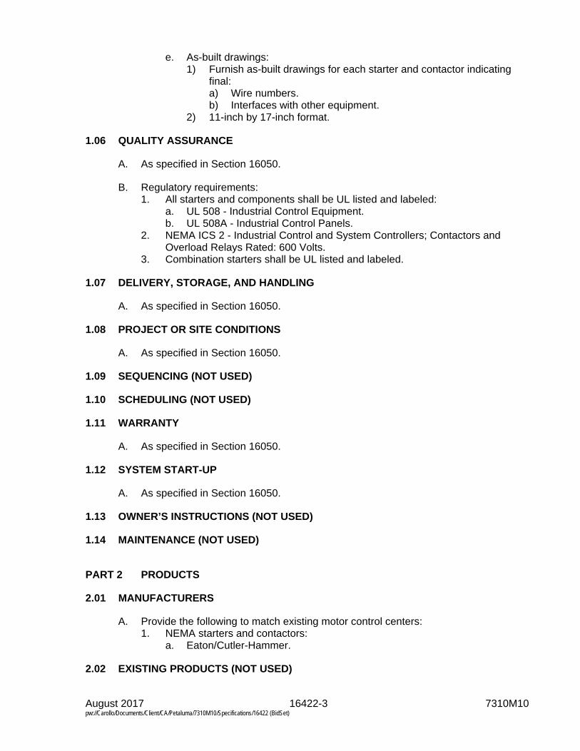
August 2017 16422-3 7310M10 pw://Carollo/Documents/Client/CA/Petaluma/7310M10/Specifications/16422 (BidSet)
e. As-built drawings: 1) Furnish as-built drawings for each starter and contactor indicating
final: a) Wire numbers. b) Interfaces with other equipment.
2) 11-inch by 17-inch format.
1.06 QUALITY ASSURANCE
A. As specified in Section 16050.
B. Regulatory requirements: 1. All starters and components shall be UL listed and labeled:
a. UL 508 - Industrial Control Equipment. b. UL 508A - Industrial Control Panels.
2. NEMA ICS 2 - Industrial Control and System Controllers; Contactors and Overload Relays Rated: 600 Volts.
3. Combination starters shall be UL listed and labeled.
1.07 DELIVERY, STORAGE, AND HANDLING
A. As specified in Section 16050.
1.08 PROJECT OR SITE CONDITIONS
A. As specified in Section 16050.
1.09 SEQUENCING (NOT USED)
1.10 SCHEDULING (NOT USED)
1.11 WARRANTY
A. As specified in Section 16050.
1.12 SYSTEM START-UP
A. As specified in Section 16050.
1.13 OWNER’S INSTRUCTIONS (NOT USED)
1.14 MAINTENANCE (NOT USED)
PART 2 PRODUCTS
2.01 MANUFACTURERS
A. Provide the following to match existing motor control centers: 1. NEMA starters and contactors:
a. Eaton/Cutler-Hammer.
2.02 EXISTING PRODUCTS (NOT USED)

August 2017 16422-4 7310M10 pw://Carollo/Documents/Client/CA/Petaluma/7310M10/Specifications/16422 (BidSet)
2.03 MATERIALS (NOT USED)
2.04 MANUFACTURED UNITS
A. General: 1. Provide combination type starters with motor circuit protector or thermal-
magnetic circuit breaker and control power transformer with ratings as indicated on the Drawings.
2. NEMA size, design, and rated: a. NEMA Size 1 minimum.
3. Coordinate motor circuit protector, thermal magnetic circuit breaker, or fusible disconnect, and overload trip ratings with nameplate horsepower and current ratings of the installed motor: a. If motors provided are different in horsepower rating than those specified
or indicated on the Drawings, provide starters coordinated to the actual motors furnished.
4. Provide starters NEMA Size 2 and larger with arc quenchers on load breaking contacts.
5. Mount extended overload reset buttons to be accessible for operation without opening starter enclosure door.
B. Full voltage starters: 1. Across-the-line full voltage magnetic starters. 2. Rated for 600 volts. 3. Electrical characteristics as indicated on the Drawings. 4. Provide positive, quick-make, quick-break mechanisms, pad lockable
enclosure doors. 5. Furnish starter with bi-metallic overload relays. 6. Double-break silver alloy contacts.
2.05 EQUIPMENT (NOT USED)
2.06 COMPONENTS
A. Molded case circuit breakers: 1. Circuit breaker type and ratings as indicated on the Drawings. 2. Provide as specified in Section 16412.
B. Contactors: 1. NEMA size as indicated on the Drawings. 2. Electrically held:
a. For lighting loads designed to withstand the initial inrush currents of ballast and lamp loads.
3. Factory adjusted and chatter free. 4. Auxiliary contacts:
a. Contact ratings as per NEMA A 600 rating: 1) Auxiliary contacts rated 10 amps at 600 volts.
b. Provide all contacts indicated on the Drawings, and any additional contacts required for proper operation.
c. Provide at least 1 normally open and 1 normally closed spare auxiliary contact.
5. Constructed in accordance with the following standards: a. UL 508.

August 2017 16422-5 7310M10 pw://Carollo/Documents/Client/CA/Petaluma/7310M10/Specifications/16422 (BidSet)
b. IEC 947-4. 1) Type 1 coordination when protected by a circuit breaker. 2) Type 2 coordination when protected by a suitable UL listed fuse.
c. IEC 801-1 parts 2 through 6.
C. Overloads: 1. Bi-metallic overload relay:
a. Class 20 protection. b. Ambient compensated. c. Interchangeable heater pack:
1) One heater per phase. 2) Coordinate with installed motor full load amps and service factor.
d. Visible trip indicator. e. Push-to-trip test. f. Isolated normally open alarm contact. g. Normally closed trip contacts. h. Manual reset.
D. Control power transformer: 1. Furnish integral control power transformer capacity to power:
a. All motor controls; Motor and starter accessories indicated on the Drawings or specified.
2. Primary and secondary fusing as indicated on the Drawings: a. Fusing sized by the manufacturer for the rating of the transformer
furnished. 3. Control power transformer secondary voltage:
a. As indicated on the Drawings.
2.07 ACCESSORIES
A. Lugs and terminals: 1. For all external connections of No. 6 AWG and larger. 2. UL listed for either copper or aluminum conductors.
B. Surge protective devices: 1. Furnish surge protection devices across the coil of each starter, contactor, and
relay.
C. Pilot devices: 1. Provide pilot lights, switches, elapsed time meters, and other devices as
specified or as indicated on the Drawings. 2. As specified in Section 17710.
D. Nameplates and wire markers: 1. As specified in Section 16075.
2.08 MIXES (NOT USED)
2.09 FABRICATION (NOT USED)
2.10 FINISHES (NOT USED)

August 2017 16422-6 7310M10 pw://Carollo/Documents/Client/CA/Petaluma/7310M10/Specifications/16422 (BidSet)
2.11 SOURCE QUALITY CONTROL
PART 3 EXECUTION
3.01 EXAMINATION (NOT USED)
3.02 PREPARATION (NOT USED)
3.03 INSTALLATION
A. As specified in Section 16050.
B. Install starters in the existing motor control centers as indicated on the Drawings.
3.04 ERECTION, INSTALLATION, APPLICATION, CONSTRUCTION (NOT USED)
3.05 REPAIR/RESTORATION (NOT USED)
3.06 RE-INSTALLATION (NOT USED)
3.07 COMMISSIONING
A. As specified in Section 01756.
B. Factory testing: 1. Owner and Engineer will witness the factory acceptance test as specified in
Section 16050.
3.08 FIELD QUALITY CONTROL
A. As specified in Section 16050.
3.09 ADJUSTING
A. Make all adjustments as necessary and recommended by the manufacturer, Engineer, or testing firm.
B. Set all overloads and motor circuit protectors based on the nameplate values of the installed motor.
3.10 CLEANING
A. As specified in Section 16050.
3.11 PROTECTION
A. As specified in Section 16050.
3.12 SCHEDULES (NOT USED)
END OF SECTION

August 2017 16510-1 7310M10 pw://Carollo/Documents/Client/CA/Petaluma/7310M10/Specifications/16510 (BidSet)
SECTION 16510
LIGHTING: LED LUMINAIRES
PART 1 GENERAL
1.01 SUMMARY
A. Section includes: LED luminaires, drivers, poles, and accessories.
B. Related sections: 1. Section 01330 - Submittal Procedures. 2. Section 01756 - Commissioning. 3. Section 16050 - Common Work Results for Electrical.
1.02 REFERENCES
A. As specified in Section 16050.
B. Institute of Electrical and Electronics Engineers (IEEE): 1. C62.41 - IEEE Recommended Practice for Surge Voltages in Low-Voltage AC
Power Circuits.
C. Illuminating Engineering Society of North America (IESNA): 1. LM-79 - IES Approved Method for the Electrical and Photometric
Measurements of Solid-State Lighting Products. 2. LM-80 - IES Approved Method: Measuring Lumen Maintenance of LED Light
Sources. 3. TM-21 - Projecting Long Term Lumen Maintenance of LED Light Sources.
D. National Electrical Manufacturers Association (NEMA): 1. 410 - Performance Testing for Lighting Controls and Switching Devices with
Electronic Drivers and Discharge Ballasts.
E. Underwriters Laboratories (UL): 1. 1598 - Luminaires. 2. 8750 - Light Emitting Diode (LED) Equipment For Use In Lighting Products.
1.03 DEFINITIONS
A. As specified in Section 16050.
B. Specific definitions and abbreviations: 1. CCT: Correlated color temperature - Scientific scale to describe how “warm” or
how “cool” the light source is, measured in Kelvin. The lower the Kelvin temperature, the warmer the light feels, or appears.
2. CRI: Color Rendering Index - A quantitative measure of the ability of a light source to reveal the colors of various objects faithfully in comparison with an ideal or natural light source.
3. Driver - Device that manages power and controls the current flow from AC to DC for an LED lighting product.

August 2017 16510-2 7310M10 pw://Carollo/Documents/Client/CA/Petaluma/7310M10/Specifications/16510 (BidSet)
4. Efficacy - Lumen output of a light source per unit of power supplied to that source (lumens per watt).
5. EMI: Electromagnetic Interference - Electrical interference (noise) generated by electrical and electronic devices.
6. FC: Foot Candles - Measure of light level on a surface being illuminated. 7. L70 - The extrapolated life in hours of the luminaire when the luminous output
depreciates 30 percent from initial values. 8. LED: Light emitting diode - A solid-state semiconductor device that produces
light when electrical current flows through it. 9. LED light source - See LED luminaire. 10. LED luminaire - A complete lighting unit consisting of LED-based light emitting
elements and a matched driver together with parts to distribute light, to position and protect the light emitting elements, and to connect the unit to a branch circuit.
11. Lumen - The international (SI) unit of luminous flux or quantity of light. The amount of light that is spread over a square foot of surface by one candle power when all parts of the surface are exactly one foot from the light source.
12. Lumen ambient temperature multiplier - LED light source relative lumen output when compared to a standard ambient temperature.
13. Lumen maintenance factor - How well an LED light source is able to retain its intensity when compared to new.
14. Luminaire - Lighting unit. 15. THD: Total harmonic distortion - The combined effect of harmonic Distortion
on the AC waveform produced by a driver or other device.
1.04 SYSTEM DESCRIPTION
A. Provide luminaires, and accessories for all lighting systems, complete and operable, in accordance with the requirements of the Contract Documents.
B. Individual luminaire types are indicated on the Drawings and on the Luminaire Schedule.
1.05 SUBMITTALS
A. Furnish submittals as specified in Sections 01330 and 16050.
B. Product data: 1. LED Luminaires:
a. Catalog literature for each luminaire specified, cross-referenced to the luminaire type on the Luminaire Schedule in the Drawings.
b. Provide for each luminaire type: 1) Materials. 2) Type of diffuser. 3) Hardware. 4) Gasketing. 5) Reflector. 6) Chassis. 7) Finish and color. 8) Driver type and protection. 9) LED luminaire:
a) Initial lumen output at 40 degrees Celsius ambient.

August 2017 16510-3 7310M10 pw://Carollo/Documents/Client/CA/Petaluma/7310M10/Specifications/16510 (BidSet)
b) Correlated color temperature. c) Lumen maintenance factors. d) Lumen ambient temperature multipliers. e) Drive current. f) Efficacy.
10) Picture of luminaire. 11) Dimensioned drawings:
a) Effective projected area rating for pole mounted luminaires. 12) Weight. 13) Photometric data:
a) Coefficient of utilization tables based on the IES zonal cavity system by an approved testing laboratory.
b) Luminaire dirt depreciation factor. c) Candlepower distribution curves. d) Average luminaire brightness. e) Lumen output charts.
c. Luminaire substitutions: 1) Provide complete literature for each luminaire substitution: 2) Submittals for substituted luminaires shall be sufficient for competent
comparison of the proposed luminaire to the originally specified luminaire: a) Photometric data:
(1) IES file in standard IES format. (2) Coefficient of utilization tables based on the IES zonal
cavity system by an approved testing laboratory. (3) Candlepower distribution curves. (4) Average luminaire brightness. (5) Lumen output charts. (6) Power requirements in watts and volt-amperes.
b) Calculations: (1) Provide software generated calculations showing
illuminance levels in foot-candles and power usage in watts per square foot for each of the areas in which substitutions are proposed: (a) Use surface reflectance values and luminaire light loss
factors approved by the Engineer to perform all calculations.
c) Specification sheets: (1) If lacking sufficient detail to indicate compliance with
contract documents, standard specification sheets will not be accepted. This includes, but is not limited to, luminaire type designation, manufacturer's complete catalog number, voltage, LED type, CCT, CRI, specific driver information, system efficacy, L70 life rating, and any modifications necessary to meet the requirements of the contract documents
3) Substitutions for specified luminaires will be evaluated upon quality of construction, light distribution, energy use, appearance, and maintenance.
4) Substitutions shall comply with all applicable building and energy codes.

August 2017 16510-4 7310M10 pw://Carollo/Documents/Client/CA/Petaluma/7310M10/Specifications/16510 (BidSet)
2. Driver: Provide for each driver type: a. Catalog number. b. Type of driver. c. Output wattage. d. Input voltage. e. Operating voltage range. f. Maximum input power. g. Efficiency. h. Operating line current. i. Power factor. j. Operating temperature range. k. Current output range in ambient temperatures of 30 degrees Celsius – 55
degrees Celsius. l. Surge suppression data.
3. Photocell: a. Provide for each photocell type:
1) Switching capacity. 2) Life expectancy when used on LED sources. 3) The means of adjusting the lighting pickup level. 4) Enclosure type. 5) Mounting method.
4. Luminaire poles: a. Submit complete data for each pole type including but not limited to:
1) Material. 2) Finish and color. 3) Handholes. 4) Anchoring. 5) Luminaire attachment methods and fittings. 6) Pole height. 7) Pole dimensions. 8) Bolt hole circle layout and hardware. 9) Accessories. 10) Provide the EPA wind load rating.
C. Calculations: 1. Provide complete design calculations and installation documents for pole
mounting piers and poles mounted from structures: a. Include in the calculations the wind and seismic requirements at the
project site. b. Calculations and design shall be performed by and signed by a
Professional Engineer registered in the state where the project is being constructed:
D. Record documents: 1. Update the Luminaire Schedule in the Drawings to reflect the acceptable
substitutions, after the substitution has been reviewed and accepted by the Engineer.
1.06 QUALITY ASSURANCE
A. As specified in Section 16050.

August 2017 16510-5 7310M10 pw://Carollo/Documents/Client/CA/Petaluma/7310M10/Specifications/16510 (BidSet)
1.07 DELIVERY, STORAGE, AND HANDLING
A. As specified in Section 16050.
1.08 PROJECT OR SITE CONDITIONS
A. As specified in Section 16050.
1.09 SEQUENCING (NOT USED)
1.10 SCHEDULING
A. Exterior and outdoor lighting system operation shall be demonstrated during the hours of darkness.
B. Lighting demonstration shall occur within 2 weeks before substantial completion.
1.11 WARRANTY
A. As specified in Section 16050.
B. LED luminaire: 1. 5 year warranty from the date of installation including material, workmanship,
photometrics, driver, and LED modules.
1.12 SYSTEM START-UP
A. As specified in Section 16050.
1.13 OWNER’S INSTRUCTIONS (NOT USED)
1.14 MAINTENANCE
A. Furnish 1 complete spare LED luminaire, with driver, of each type used.
PART 2 PRODUCTS
2.01 MANUFACTURERS
A. Luminaires: One of the following or equal: 1. As noted on the Luminaire Schedule.
B. Drivers: One of the following or equal: 1. Philips Advance. 2. Thomas Research. 3. eldoLED.
C. Photo-electric cells: One of the following or equal: 1. Cooper. 2. Tork. 3. Intermatic.
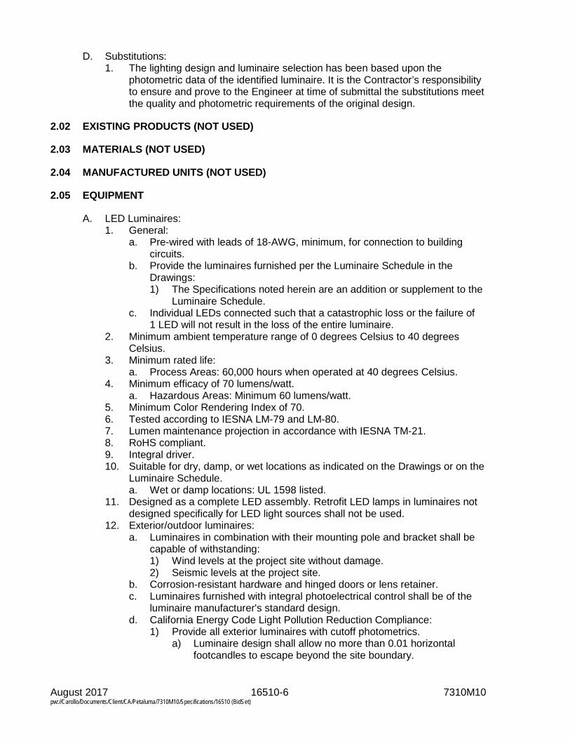
August 2017 16510-6 7310M10 pw://Carollo/Documents/Client/CA/Petaluma/7310M10/Specifications/16510 (BidSet)
D. Substitutions: 1. The lighting design and luminaire selection has been based upon the
photometric data of the identified luminaire. It is the Contractor’s responsibility to ensure and prove to the Engineer at time of submittal the substitutions meet the quality and photometric requirements of the original design.
2.02 EXISTING PRODUCTS (NOT USED)
2.03 MATERIALS (NOT USED)
2.04 MANUFACTURED UNITS (NOT USED)
2.05 EQUIPMENT
A. LED Luminaires: 1. General:
a. Pre-wired with leads of 18-AWG, minimum, for connection to building circuits.
b. Provide the luminaires furnished per the Luminaire Schedule in the Drawings: 1) The Specifications noted herein are an addition or supplement to the
Luminaire Schedule. c. Individual LEDs connected such that a catastrophic loss or the failure of
1 LED will not result in the loss of the entire luminaire. 2. Minimum ambient temperature range of 0 degrees Celsius to 40 degrees
Celsius. 3. Minimum rated life:
a. Process Areas: 60,000 hours when operated at 40 degrees Celsius. 4. Minimum efficacy of 70 lumens/watt.
a. Hazardous Areas: Minimum 60 lumens/watt. 5. Minimum Color Rendering Index of 70. 6. Tested according to IESNA LM-79 and LM-80. 7. Lumen maintenance projection in accordance with IESNA TM-21. 8. RoHS compliant. 9. Integral driver. 10. Suitable for dry, damp, or wet locations as indicated on the Drawings or on the
Luminaire Schedule. a. Wet or damp locations: UL 1598 listed.
11. Designed as a complete LED assembly. Retrofit LED lamps in luminaires not designed specifically for LED light sources shall not be used.
12. Exterior/outdoor luminaires: a. Luminaires in combination with their mounting pole and bracket shall be
capable of withstanding: 1) Wind levels at the project site without damage. 2) Seismic levels at the project site.
b. Corrosion-resistant hardware and hinged doors or lens retainer. c. Luminaires furnished with integral photoelectrical control shall be of the
luminaire manufacturer's standard design. d. California Energy Code Light Pollution Reduction Compliance:
1) Provide all exterior luminaires with cutoff photometrics. a) Luminaire design shall allow no more than 0.01 horizontal
footcandles to escape beyond the site boundary.

August 2017 16510-7 7310M10 pw://Carollo/Documents/Client/CA/Petaluma/7310M10/Specifications/16510 (BidSet)
2) Provide exterior luminaires with photocells to automatically control exterior lighting dusk to dawn to turn off or lower the lighting levels during inactive periods. Reference the Drawings for specific luminaires to be controlled.
B. Photo-electric cells: 1. Photoelectric cells for control of multiple luminaires:
a. Self-contained. b. Weatherproof. c. Provided with time-delay features. d. Sized to meet switching capacity of the circuit:
1) Based on luminaire VA as indicated on the Drawings. 2. Photoelectric cell for control of a single luminaire:
a. Integral to the luminaire.
C. Drivers: 1. Dimmable, with dimming signal protocol of 0-10 VDC or DALI. 2. Input power source:
a. As indicated on the Drawings. 3. Drive current:
a. As indicated in the Luminaire Schedule. 4. Power factor: greater than 0.90. 5. Efficiency: greater than 80 percent. 6. Total harmonic distortion (THD) of the input current less than 20 percent. 7. Rated life of 60,000 hours in an LED luminaire operated at an ambient
temperature of 40 degrees Celsius. 8. Minimum operating temperature of 0 degrees Celsius. 9. Sound rating: Class A+ or quieter. 10. UL listed Class 2 Outdoor in accordance with UL 8750. 11. In accordance with IEEE C62.41 Category A for transient protection. 12. Driver must limit inrush current:
a. Meet or exceed NEMA 410 driver inrush standard: 1) 230 Amps per 10 Amp load with a maximum of 106 Amps squared-
seconds at 120V. 2) 430 Amps per 10 Amp load with a maximum of 370 Amps squared-
seconds at 277V.
2.06 COMPONENTS
A. Luminaire poles: 1. As indicated on the Luminaire Schedule. 2. Anchor bolts:
a. Use anchor bolts, bolts, or welded studs for anchors for resisting seismic and wind forces. 1) Standard hex bolt head. 2) Do not use anchor bolts fabricated from rod stock with an L or
J-shape. b. Complete with leveling shims.
3. Anchor base: a. Fabricated from the same type of material as the pole shaft. b. Base plate to telescope the pole shaft. c. Welded top and bottom along the entire perimeter.
August 2017 16510-8 7310M10 pw://Carollo/Documents/Client/CA/Petaluma/7310M10/Specifications/16510 (BidSet)
d. With slotted bolt holes on the bolt circles as submitted. 4. Pole shaft:
a. As indicated on the Luminaire Schedule. 5. Handhole:
a. Reinforced handhole located approximately 18 inches above the base. b. Complete with cover fabricated from the same material as the pole shaft
and stainless steel attachment screws. c. With an integral ground connection nut, 1/2 inch by 13 inch UNC welded
to the pole for connection to the grounding system. 6. Shroud:
a. Fabricated from the same type of material as the pole shaft. b. 1-piece formed channel section that shall conform to the pole shaft taper. c. Secured by a locking device with provisions for a padlock to prevent
accidental lowering. 7. Fastening hardware:
a. All fasteners shall be stainless steel. 8. Finish:
a. As indicated on the Luminaire Schedule.
2.07 ACCESSORIES
A. Pole mounted convenience outlet: 1. Where indicated, furnish a 120 Volt, GFCI protected receptacle:
a. Integrally mounted in the pole shaft at 24 inches above the base. 2. Complete with corrosion resistant and weatherproof cover.
2.08 MIXES (NOT USED)
2.09 FABRICATION (NOT USED)
2.10 FINISHES (NOT USED)
2.11 SOURCE QUALITY CONTROL (NOT USED)
PART 3 EXECUTION
3.01 EXAMINATION (NOT USED)
3.02 PREPARATION (NOT USED)
3.03 INSTALLATION
A. As specified in Section 16050.
B. Install luminaires per the manufacturer’s guidelines and submitted installation calculations to meet seismic and wind requirements at the project site.
C. Special techniques: 1. Coordinate luminaire locations with work of other trades to prevent obstruction
of light from the fixtures.
August 2017 16510-9 7310M10 pw://Carollo/Documents/Client/CA/Petaluma/7310M10/Specifications/16510 (BidSet)
D. Luminaire poles: 1. Set poles on anchor bolts and secured with double nuts on each bolt. 2. Dry-pack the pole base, after the luminaire and pole has been leveled and
plumbed. 3. Bond metal poles to the plant grounding system, utilizing a ground lug
connection within the pole: a. Route ground conductor through pier and pole base sleeve using
Schedule 40 PVC conduit.
3.04 ERECTION, INSTALLATION, APPLICATION, CONSTRUCTION (NOT USED)
3.05 REPAIR/RESTORATION (NOT USED)
3.06 RE-INSTALLATION (NOT USED)
3.07 COMMISSIONING
A. As specified in Section 01756.
3.08 FIELD QUALITY CONTROL
A. As specified in Section 16050.
3.09 ADJUSTING
A. Aim and verify all exterior and outdoor luminaires alignment, during dark evening hours, as directed by Owner or the Engineer.
3.10 CLEANING
A. As specified in Section 16050.
B. Clean all lenses, diffusers, and reflectors.
C. Refinish all luminaires’ trim, poles, and support brackets, where finish has been damaged.
D. Clean all LED luminaires used during construction for construction lighting, before substantial completion.
3.11 PROTECTION
A. As specified in Section 16050.
3.12 SCHEDULES
A. Refer to the Luminaire Schedule in the Drawings.
END OF SECTION

August 2017 16510-10 7310M10 pw://Carollo/Documents/Client/CA/Petaluma/7310M10/Specifications/16510 (BidSet)

August 2017 16950-1 7310M10 pw://Carollo/Documents/Client/CA/Petaluma/7310M10/Specifications/16950 (BidSet)
SECTION 16950
FIELD ELECTRICAL ACCEPTANCE TESTS
PART 1 GENERAL
1.01 SUMMARY
A. Section includes: 1. Responsibilities for testing the electrical installation. 2. Adjusting and calibration. 3. Acceptance tests.
B. Related sections: 1. Section 01330 - Submittal Procedures. 2. Section 01756 - Commissioning. 3. Section 16050 - Common Work Results for Electrical.
C. Copyright information: 1. Some portions of this Section are copyrighted by the InterNational Electrical
Testing Association, Inc (NETA). See NETA publication ATS for details.
1.02 REFERENCES
A. As specified in Section 16050.
B. American National Standards Institute (ANSI).
C. Institute of Electrical and Electronics Engineers (IEEE): 1. 43 - IEEE Recommended Practice for Testing Insulation Resistance of
Rotating Machinery.
D. Insulated Cable Engineer’s Association (ICEA).
E. InterNational Electrical Testing Association (NETA). 1. ATS-2009 Standard for Standard for Acceptance Testing Specifications for
Electrical Power Equipment and Systems.
F. International Electrotechnical Commission (IEC).
G. Manufacturer’s testing recommendations and instruction manuals.
H. National Fire Protection Association (NFPA): 1. 70 – National Electrical Code (NEC). 2. 110 - Standard for Emergency and Standby Power Systems.
I. National Institute of Standards and Technology (NIST).
J. Specification sections for the electrical equipment being tested.
K. Shop drawings.

August 2017 16950-2 7310M10 pw://Carollo/Documents/Client/CA/Petaluma/7310M10/Specifications/16950 (BidSet)
1.03 DEFINITIONS
A. As specified in Sections 01756 and 16050.
B. Specific definitions: 1. Testing laboratory: The organization performing acceptance tests.
1.04 SYSTEM DESCRIPTION
A. Testing of all electrical equipment installed under this Contract in accordance with the manufacturer’s requirements and as specified in this Section.
B. Conduct all tests in the presence of the Engineer or the Engineer’s representative:
C. Engineer will witness all visual, mechanical, and electrical tests, and inspections.
D. The testing and inspections shall verify that the equipment is operational within the tolerances required and expected by the manufacturer, and these Specifications.
E. Responsibilities: 1. Contractor responsibilities:
a. Ensure that all resources are made available for testing, and that all testing requirements are met.
2. Electrical subcontractor responsibilities: a. Perform routine tests during installation. b. Demonstrate operation of electrical equipment. c. Commission the electrical installation. d. Provide the necessary services during testing, and provide these services
to the testing laboratory, Contractor, and other subcontractors, including but not limited to: 1) Providing electrical power as required. 2) Operating of electrical equipment in conjunction with testing of other
equipment. 3) Activating and shutting down electrical circuits. 4) Making and recording electrical measurements. 5) Replacing blown fuses. 6) Installing temporary jumpers.
3. Testing laboratory responsibilities: a. Perform all acceptance tests specified in this Section. b. Provide all required equipment, materials, labor, and technical support
during acceptance tests.
F. Upon completion of testing or calibration, attach a label to all serviced devices: 1. The label shall indicate the date serviced and the company that performed the
service.
1.05 SUBMITTALS
A. Furnish submittals as specified in Sections 01330 and 16050.

August 2017 16950-3 7310M10 pw://Carollo/Documents/Client/CA/Petaluma/7310M10/Specifications/16950 (BidSet)
B. LAN cable test form: 1. LAN cable test reports:
a. Submit 3 copies of test reports showing the results of all tests specified in this Section: 1) Test type. 2) Test location. 3) Test date. 4) Cable number. 5) Cable length. 6) Certification that the cable meets or exceeds the specified standard.
b. Furnish hard copy and electronic copy for all traces.
C. Manufacturers’ testing procedures: 1. Submit manufacturers’ recommended testing procedures and acceptable test
results for review by the Engineer.
D. Test report: 1. Include the following:
a. Summary of Project. b. Description of equipment tested. c. Description of tests performed. d. Test results. e. Conclusions and recommendations. f. Completed test forms. g. List of test equipment used and calibration dates. h. LAN cable test reports.
E. Testing laboratory qualifications: 1. Submit a complete resume and statement of qualifications from the proposed
testing laboratory detailing their experiences in performing the tests specified: a. This statement will be used to determine whether the laboratory is
acceptable, and shall include: 1) Corporate history and references. 2) Resume of individual performing test. 3) Equipment list and test calibration data.
F. Division of responsibilities: 1. Submit a list identifying who is responsible for performing each portion of the
testing.
1.06 QUALITY ASSURANCE
A. As specified in Section 16050.
B. Testing laboratory qualifications: 1. The testing laboratory may be qualified testing personnel from the electrical
subcontractor’s staff or an independent testing company. 2. Selection of the testing laboratory and testing personnel is subject to approval
by the Engineer based on testing experience and certifications of the individuals and testing capabilities of the organization.
1.07 DELIVERY, STORAGE, AND PROTECTION (NOT USED)

August 2017 16950-4 7310M10 pw://Carollo/Documents/Client/CA/Petaluma/7310M10/Specifications/16950 (BidSet)
1.08 PROJECT OR SITE CONDITIONS
A. As specified in Section 16050.
1.09 SEQUENCING
A. At least 30 days before commencement of the acceptance tests, submit the manufacturer’s complete field testing procedures to the Engineer and to the testing laboratory, complete with expected test results and tolerances for all equipment to be tested.
B. Perform testing in the following sequence: 1. Perform routine tests as the equipment is installed including:
a. Insulation-resistance tests. b. Continuity tests. c. Rotational tests.
2. Adjusting and preliminary calibration. 3. Acceptance tests. 4. Demonstration. 5. Commissioning and plant start-up.
1.10 SCHEDULING (NOT USED)
1.11 WARRANTY
A. As specified in Section 16050.
1.12 SYSTEM START-UP (NOT USED)
1.13 OWNER'S INSTRUCTIONS (NOT USED)
1.14 MAINTENANCE (NOT USED)
PART 2 PRODUCTS (NOT USED)
PART 3 EXECUTION
3.01 EXAMINATION (NOT USED)
3.02 PREPARATION
A. Test instrument calibration: 1. Utilize a testing laboratory with a calibration program which maintains all
applicable test instrumentation within rated accuracy. 2. The accuracy shall be traceable to the NIST in an unbroken chain. 3. Calibrate instruments in accordance with the following frequency schedule:
a. Field instruments: 6 months maximum. b. Laboratory instruments: 12 months maximum. c. Leased specialty equipment where the accuracy is guaranteed by the
lessor (such as Doble): 12 months maximum. 4. Dated calibration labels shall be visible on all test equipment.

August 2017 16950-5 7310M10 pw://Carollo/Documents/Client/CA/Petaluma/7310M10/Specifications/16950 (BidSet)
5. Maintain an up-to-date instrument calibration record for each test instrument: a. The records shall show the date and results of each calibration or test.
6. Maintain an up-to-date instrument calibration instruction and procedure for each test instrument.
B. Do not begin testing until the following conditions have been met: 1. All instruments required are available and in proper operating condition. 2. All required dispensable materials such as solvents, rags, and brushes are
available. 3. All equipment handling devices such as cranes, vehicles, chain falls and other
lifting equipment are available or scheduled. 4. All instruction books, calibration curves, or other printed material to cover the
electrical devices are available. 5. Data sheets to record all test results are available.
3.03 INSTALLATION (NOT USED)
3.04 ERECTION, INSTALLATION, APPLICATION, CONSTRUCTION (NOT USED)
3.05 REPAIR/RESTORATION (NOT USED)
3.06 RE-INSTALLATION (NOT USED)
3.07 COMMISSIONING
A. As specified in Section 01756.
3.08 FIELD QUALITY CONTROL
A. Low voltage cables, 600 volt maximum: 1. Visual and mechanical inspection:
a. Compare cable data with the Drawings and Specifications. b. Inspect exposed sections of cable for physical damage and correct
connection as indicated on the Drawings. c. Inspect bolted electrical connections for high resistance by 1 of the
following methods: 1) Use of low-resistance ohmmeter. 2) Verify tightness of accessible bolted electrical connections by the
calibrated torque wrench method: a) Refer to manufacturer’s instructions for proper foot-pound levels
or NETA ATS tables. d. Inspect compression applied connectors for correct cable match and
indentation. e. Inspect for correct identification and arrangement. f. Inspect cable jacket insulation and condition.
2. Electrical tests: a. Perform resistance measurements through bolted connections with a low-
resistance ohmmeter. b. Perform insulation resistance test on each conductor with respect to
ground and adjacent conductors: 1) Applied potential shall be 500 volts dc for 300 volt rated cable and
1,000 volts dc for 600 volt rated cable. 2) Test duration shall be 1 minute.

August 2017 16950-6 7310M10 pw://Carollo/Documents/Client/CA/Petaluma/7310M10/Specifications/16950 (BidSet)
c. Perform continuity tests to insure correct cable connection. d. Verify uniform resistance of parallel conductors.
3. Test values: a. Compare bolted connection resistance values to values of similar
connections: 1) Investigate values which deviate from those of similar bolted
connections by more than 50 percent of the lowest value. b. Insulation-resistance values shall be in accordance with manufacturer’s
published data: 1) Refer to NETA ATS tables in the absence of manufacturer’s
published data. 2) Investigate values of insulation-resistance less than the allowable
minimum. c. Cable shall exhibit continuity. d. Investigate deviations in resistance between parallel conductors.
B. Low voltage molded case and insulated case circuit breakers: 1. Visual and mechanical inspection:
a. Compare equipment nameplate data with the Contract Documents. b. Inspect physical and mechanical condition. c. Inspect anchorage and alignment. d. Verify that all maintenance devices are available for servicing and
operating the breaker. e. Verify the unit is clean. f. Verify the arc chutes are intact. g. Inspect moving and stationary contacts for condition and alignment. h. Verify that primary and secondary contact wipe and other dimensions vital
to satisfactory operation of the breaker are correct. i. Perform all mechanical operator and contact alignment tests on both the
breaker and its operating mechanism in accordance with manufacturers published data.
j. Operate circuit breaker to ensure smooth operation. k. Inspect bolted electrical connections for high resistance by one of the
following methods: 1) Use of low-resistance ohmmeter. 2) Verify tightness of accessible bolted electrical connections by the
calibrated torque wrench method: a) Refer to manufacturer’s instructions for proper foot-pound levels
or NETA ATS tables. l. Inspect operating mechanism, contacts, and arc chutes in unsealed units. m. Verify cell fit and element alignment. n. Verify racking mechanism operation. o. Verify appropriate lubrication on moving current-carrying parts and on
moving and sliding surfaces. p. Perform adjustments for final protective device settings in accordance with
the coordination study. q. Record as-found and as-left operation counter readings.
2. Electrical tests: a. Perform resistance measurements through bolted connections with a low-
resistance ohmmeter.

August 2017 16950-7 7310M10 pw://Carollo/Documents/Client/CA/Petaluma/7310M10/Specifications/16950 (BidSet)
b. Perform insulation-resistance tests for 1 minute on each pole, phase-to-phase and phase-to-ground with the circuit breaker closed and across each open pole: 1) Apply voltage in accordance with manufacturer’s published data. 2) Refer to NETA ATS tables in the absence of manufacturer’s
published data. c. Perform a contact/pole-resistance test. d. Determine long-time pickup and delay by primary current injection. e. Determine short-time pickup and delay by primary current injection. f. Determine ground-fault pickup and delay by primary current injection. g. Determine instantaneous pickup value by primary current injection. h. Perform minimum pickup voltage tests on shunt trip and close coils in
accordance with manufacturer’s published data. i. Verify correct operation of any auxiliary features such as trip and pickup
indicators, zone interlocking, electrical close and trip operation, trip-free, anti-pump function and trip unit battery condition: 1) Reset all trip logs and indicators.
j. Verify operation of charging mechanism. 3. Test values:
a. Compare bolted connection resistance values to values of similar connections: 1) Investigate values which deviate from those of similar bolted
connections by more than 50 percent of the lowest value. b. Bolt-torque levels shall be in accordance with manufacturer’s published
data: 1) Refer to NETA ATS tables in the absence of manufacturer’s
published data. c. Insulation-resistance values shall be in accordance with manufacturer’s
published data: 1) Refer to NETA ATS tables in the absence of manufacturer’s
published data. 2) Investigate values of insulation-resistance less than the allowable
minimum. d. Microhm or dc millivolt drop values shall not exceed the high levels of the
normal range as indicated in the manufacturer’s published data: 1) If manufacturer’s data is not available, investigate any values which
deviate from adjacent poles or similar breakers by more than 50 percent of the lowest value.
e. Long-time pickup values shall be as specified, and the trip characteristic shall not exceed manufacturer’s published time-current characteristic tolerance band including adjustment factors: 1) If manufacturer’s curves are not available, trip times shall not exceed
the value shown in NETA ATS tables. f. Short-time pickup values shall be as specified, and the trip characteristic
shall not exceed manufacturer’s published time-current tolerance band. g. Ground fault pickup values shall be as specified, and the trip characteristic
shall not exceed manufacturer’s published time-current tolerance band. h. Instantaneous pickup values shall be as specified and within
manufacturer’s published tolerances: 1) Refer to NETA ATS tables in the absence of manufacturer’s
published data.

August 2017 16950-8 7310M10 pw://Carollo/Documents/Client/CA/Petaluma/7310M10/Specifications/16950 (BidSet)
i. Pickup values and trip characteristics shall be within manufacturer’s published tolerances.
j. Minimum pickup voltage of the shunt trip and close coils shall conform to the manufacturer’s published data: 1) Refer to NETA ATS tables in the absence of manufacturer’s
published data. k. Breaker open, close, trip, trip-free, anti-pump, and auxiliary features shall
function as designed. l. The charging mechanism shall operate in accordance with manufacturer’s
published data.
C. Rotating machinery: 1. Visual and mechanical inspection:
a. Compare equipment nameplate information with the Contract Documents. b. Inspect physical and mechanical condition. c. Inspect anchorage, alignment, and grounding. d. Inspect air baffles, filter media, cooling fans, slip rings, brushes, brush
rigging, and shaft current discharge devices. e. Inspect bolted electrical connections for high resistance using one of the
following methods: 1) Use of low-resistance ohmmeter. 2) Verify tightness of accessible bolted electrical connections by
calibrated torque wrench method: a) Refer to manufacturer’s instructions for proper foot-pound levels
or NETA ATS tables. f. Perform special tests such as gap spacing and machine alignment if
applicable. g. Manually rotate the rotor and check for problems with the bearings or
shaft. h. Rotate the shaft and measure and record the shaft extension runout. i. Verify correct application of appropriate lubrication and lubrication
systems. j. Verify that resistance temperature detector (RTD) circuits conform to that
indicated on the Drawings. 2. Electrical tests:
a. Perform resistance measurements through bolted connections with a low-resistance ohmmeter.
b. Perform insulation-resistance test in accordance with IEEE 43: 1) On motors 200 horsepower and smaller, test duration shall be
1 minute. Calculate dielectric absorption ratio. 2) On motors larger than 200 horsepower, test duration shall be
10 minutes. Calculate polarization index. c. Perform dc dielectric withstand voltage tests on machines rated at
2,300 volts and greater in accordance with IEEE 95. 1) IEEE 95 for dc dielectric withstand voltage tests. 2) NEMA MG1 for ac dielectric withstand voltage tests.
d. Perform phase-to-phase stator resistance test on machines rated at 2,300 volts and greater.
e. Perform insulation-resistance test on insulated bearings in accordance with manufacturer’s published data.
f. Test surge protection devices as specified in this Section. g. Test motor starter as specified in this Section.

August 2017 16950-9 7310M10 pw://Carollo/Documents/Client/CA/Petaluma/7310M10/Specifications/16950 (BidSet)
h. Perform resistance tests on resistance temperature detector (RTD) circuits.
i. Verify operation of motor space heater.
j. Perform a rotation test to ensure correct shaft rotation. k. Measure running current and evaluate relative to load conditions and
nameplate full-load amperes. 3. Test values:
a. Inspection: 1) Air baffles shall be clean and installed in accordance with the
manufacturer’s published data. 2) Filter media shall be clean and installed in accordance with the
manufacturer’s published data. 3) Cooling fans shall operate. 4) Slip ring alignment shall be within manufacturer’s published
tolerances. 5) Brush alignment shall be within manufacturer’s published tolerances. 6) Brush rigging shall be within manufacturer’s published tolerances.
b. Compare bolted connection resistance values to values of similar connections: 1) Investigate values which deviate from those of similar bolted
connections by more than 50 percent of the lowest value. c. Bolt-torque levels shall be in accordance with manufacturer’s published
data: 1) Refer to NETA ATS tables in the absence of manufacturer’s
published data. d. Air-gap spacing and machine alignment shall be in accordance with
manufacturer’s published data. e. The recommended minimum insulation-resistance (IR1 min) test results in
megohms shall be as specified in this Section. 1) The polarization index value shall not be less than 2.0. 2) The dielectric absorption ratio shall not be less than 1.4.
f. If no evidence of distress or insulation failure is observed by the end of the total time of voltage application during the dielectric withstand test, the test specimen is considered to have passed the test.
g. Investigate phase-to-phase stator resistance values that deviate by more than 10 percent.
h. Bearing insulation-resistance measurements shall be within manufacturer’s published tolerances: 1) In the absence of manufacturer’s published data compare values of
similar machines. i. Test results of surge protection devices shall be as specified in this
Section. j. Test results of motor starter equipment shall be as specified in this
Section. k. RTD circuits shall conform to the design intent and machine protection
device manufacturer’s published data. l. Heaters shall be operational. m. Machine rotation should match required rotation of connected load. n. Running phase-to-phase voltages should be within 1.0 percent. Running
currents shall be balanced and proportional to load condition and nameplate data.

August 2017 16950-10 7310M10 pw://Carollo/Documents/Client/CA/Petaluma/7310M10/Specifications/16950 (BidSet)
D. Motor starters, low voltage: 1. Visual and mechanical inspection:
a. Compare equipment nameplate information with the Contract Documents. b. Inspect physical and mechanical condition. c. Inspect anchorage, alignment, and grounding. d. Verify the unit is clean. e. Inspect contactors:
1) Verify mechanical operation. 2) Verify contact gap, wipe, alignment, and pressure are in accordance
with manufacturer’s published data. f. Motor-running protection:
1) Verify overload element rating is correct for its application. 2) If motor running protection is provided by fuses, verify correct fuse
rating. g. Inspect bolted electrical connections for high resistance using one of the
following methods: 1) Use of low-resistance ohmmeter. 2) Verify tightness of accessible bolted electrical connections by
calibrated torque wrench method: a) Refer to manufacturer’s instructions for proper foot-pound levels
or NETA ATS tables. h. Lubrication requirements:
1) Verify appropriate lubrication on moving current-carrying parts. 2) Verify appropriate lubrication on moving and sliding surfaces.
2. Electrical tests: a. Perform resistance measurements through bolted connections with a low-
resistance ohmmeter. b. Perform insulation-resistance tests for 1 minute on each pole, phase-to-
phase and phase to ground with the starter closed, and across each open pole for 1 minute: 1) Test voltage shall be in accordance with manufacturer’s published
data. 2) Refer to NETA ATS tables in the absence of manufacturer’s
published data. c. Test motor protection devices in accordance with manufacturer’s
published data. d. Test circuit breakers as specified in this Section. e. Perform operational tests by initiating control devices.
3. Test values: a. Compare bolted connection resistance values to values of similar
connections: 1) Investigate values which deviate from those of similar bolted
connections by more than 50 percent of the lowest value. b. Bolt-torque levels shall be in accordance with manufacturer’s published
data: 1) Refer to NETA ATS tables in the absence of manufacturer’s
published data. c. Insulation-resistance values shall be in accordance with manufacturer’s
published data: 1) Refer to NETA ATS tables in the absence of manufacturer’s
published data.
August 2017 16950-11 7310M10 pw://Carollo/Documents/Client/CA/Petaluma/7310M10/Specifications/16950 (BidSet)
2) Investigate values of insulation-resistance less than the allowable minimum.
d. Motor protection parameters shall be in accordance with manufacturer’s published data.
e. Circuit breaker test results shall as specified in this Section. f. Control devices shall perform in accordance with system design
requirements.
E. Variable frequency drive systems: 1. Visual and mechanical inspection:
a. Compare equipment nameplate data with the Contract Documents. b. Inspect physical and mechanical condition. c. Inspect anchorage, alignment, and grounding. d. Verify the unit is clean. e. Ensure vent path openings are free from debris and that heat transfer
surfaces are clean. f. Verify correct connections of circuit boards, wiring, disconnects, and
ribbon cables. g. Motor running protection:
1) Verify drive overcurrent setpoints are correct for their application. 2) If drive is used to operate multiple motors, verify individual overload
element ratings are correct for their application. 3) Apply minimum and maximum speed setpoints. Verify setpoints are
within limitations of the load coupled to the motor. h. Inspect bolted electrical connections for high resistance using one of the
following methods: 1) Use of low-resistance ohmmeter. 2) Verify tightness of accessible bolted electrical connections by the
calibrated torque wrench method: a) Refer to manufacturer’s instructions for proper foot-pound levels
or NETA ATS tables. i. Verify correct fuse sizing in accordance with manufacturer’s published
data. j. Perform visual and mechanical inspection of input circuit breaker as
specified in this Section. 2. Electrical tests:
a. Perform resistance measurements through bolted connections with low resistance ohmmeter.
b. Test the motor overload relay elements by injecting primary current through the overload circuit and monitoring trip time of the overload element.
c. Test for the following parameters in accordance with relay calibration procedures specified in this Section or as recommended by the manufacturer: 1) Input phase loss protection. 2) Input overvoltage protection. 3) Output phase rotation. 4) Overtemperature protection. 5) Direct current overvoltage protection. 6) Overfrequency protection. 7) Drive overload protection. 8) Fault alarm outputs.

August 2017 16950-12 7310M10 pw://Carollo/Documents/Client/CA/Petaluma/7310M10/Specifications/16950 (BidSet)
d. Perform continuity tests on bonding conductors as specified in this Section.
e. Perform start-up of drive in accordance with manufacturer’s published data. Calibrate drive to the system’s minimum and maximum speed control signals.
f. Perform operational tests by initiating control devices: 1) Slowly vary drive speed between minimum and maximum. Observe
motor and load for unusual noise or vibration. 2) Verify operation of drive from remote start/stop and speed control
signals. g. Perform electrical tests of input circuit breaker as specified in this Section.
3. Test values: a. Compare bolted connection resistance values to values of similar
connections: 1) Investigate values which deviate from those of similar bolted
connections by more than 50 percent of the lowest value. b. Bolt-torque levels shall be in accordance with manufacturer’s published
data: 1) Refer to NETA ATS tables in the absence of manufacturer’s
published data. c. Overload test trip times at 300 percent of overload element rating shall be
in accordance with manufacturer’s published time-current curve. d. Test values for input circuit breaker shall be as specified in this Section. e. Relay calibration results shall be as specified in this Section. f. Continuity of bonding conductors shall be as specified in this Section. g. Control devices shall perform in accordance with system requirements. h. Operational tests shall conform to system design requirements.
F. LAN cable testing: 1. Visual and mechanical inspections:
a. Compare cable type and connections with that indicated on the Drawings and specified in the Specifications.
b. Inspect cable and connectors for physical and mechanical damage. c. Verify that all connectors are correctly installed.
2. Pre-testing: a. Test individual cables before installation:
1) Before physical placement of the cable, test each cable while on the spool with a LAN certification test device.
2) Before the cable is installed, verify that the cable conforms to the manufacturer’s attenuation specification and that no damage has been done to the cable during shipping or handling.
3) The test shall be fully documented and the results submitted to the Engineer, including a hard copy of all traces, before placement of the cable.
4) The Engineer shall be notified if a cable fails to meet specification and the cable shall not be installed unless otherwise directed by the Engineer.
3. Electrical tests: a. Perform cable end-to-end testing on all installed cables after installation of
connectors from both ends of the cable. b. Test shall include cable system performance tests and confirm the
absence of wiring errors.

August 2017 16950-13 7310M10 pw://Carollo/Documents/Client/CA/Petaluma/7310M10/Specifications/16950 (BidSet)
4. Test results: a. Cables shall meet or exceed TIA standards for a Category 6 installation.
5. Test equipment: a. LAN certification equipment used for the testing shall be capable of testing
Category 6 cable installation to TIA proposed Level III accuracy. Tests performed shall include: 1) Near end cross talk. 2) Attenuation. 3) Equal level far end cross talk. 4) Return loss. 5) Ambient noise. 6) Effective cable length. 7) Propagation delay. 8) Continuity/loop resistance.
b. LAN certification test equipment shall be able to store and produce plots of the test results.
c. Acceptable manufacturers: The following or equal: 1) Agilent Technologies, WireScope 350.
3.09 ADJUSTING (NOT USED)
3.10 CLEANING
A. As specified in Section 16050.
B. After the acceptance tests have been completed, dispose of all testing expendables, vacuum all cabinets, and sweep clean all surrounding areas.
3.11 PROTECTION
A. As specified in Section 16050.
3.12 SCHEDULES (NOT USED)
END OF SECTION


August 2017 17050-1 7310M10 pw://Carollo/Documents/Client/CA/Petaluma/7310M10/Specifications/17050 (BidSet)
SECTION 17050
COMMON WORK RESULTS FOR PROCESS CONTROL AND INSTRUMENTATION SYSTEMS
PART 1 GENERAL
1.01 SUMMARY
A. Section includes: 1. General requirements applicable to all Process Control and Instrumentation
Work. 2. General requirements for process control and instrumentation submittals. 3. As specified in this Section, some PLC programming and SCADA/HMI
software configuration will be provided by the Owner, through the services of a consultant, hereinafter referred to as the Programmer.
B. Related sections: 1. General Conditions. 2. Special Conditions. 3. Section 01110 - Summary of Work. 4. Section 01140 - Work Restrictions. 5. Section 01292 - Schedule of Values. 6. Section 01312 - Project Meetings. 7. Section 01324B - Progress Schedules and Reports. 8. Section 01329 - Safety Plan. 9. Section 01330 - Submittal Procedures. 10. Section 01410 - Regulatory Requirements. 11. Section 01450 - Quality Control. 12. Section 01600 - Product Requirements. 13. Section 01610 - Project Design Criteria. 14. Section 01612 - Seismic Design Criteria. 15. Section 01614 - Wind Design Criteria. 16. Section 01756 - Commissioning. 17. Section 01770 - Closeout Procedures. 18. Section 01782 - Operation and Maintenance Data. 19. Section 16050 - Common Work Results for Electrical. 20. Section 16075 - Identification for Electrical Systems. 21. Section 17720 - Control Systems: Programmable Logic Controllers. 22. Section 17950 - Testing, Calibration, and Commissioning.
C. Interfaces to equipment, instruments, and other components: 1. Drawings, Specifications, and overall design are based on preliminary
information furnished by various equipment manufacturers, which identify a minimum scope of supply from the manufacturers. This information pertains to, but is not limited to, instruments, control devices, electrical equipment, packaged mechanical systems, and control equipment provided with mechanical systems.
2. Provide all material and labor needed to install the actual equipment furnished, include all costs to add any additional instruments, wiring, control system inputs/outputs, controls, interlocks, electrical hardware etc., which may be

August 2017 17050-2 7310M10 pw://Carollo/Documents/Client/CA/Petaluma/7310M10/Specifications/17050 (BidSet)
necessary to make a complete, functional installation based on the actual equipment furnished: a. Make all changes necessary to meet the manufacturer’s wiring
requirements. 3. Submit all such changes and additions to the Engineer for acceptance as
specified in General Conditions. 4. Review the complete set of Drawings and Specifications in order to ensure
that all items related to the instrumentation and control systems are completely accounted for. Include any items indicated on the Drawings or in Specifications from another discipline in the scope of Work: a. If a conflict between Drawings and Specifications is discovered, refer
conflict to the Engineer as soon as possible for resolution. 5. Loop drawings:
a. Provide complete loop drawings for all systems, including packaged equipment furnished as part of a vendor furnished package, and for all pre-purchased equipment.
b. The form, minimum level of detail, and format for the loop drawings must match that of the sample loop drawings included in the Contract Documents.
c. The Owner and Engineer are not responsible for providing detailed loop diagrams for Contractor furnished equipment.
D. All instrumentation, and control equipment and systems for the entire project to comply with the requirements specified in the Instrumentation and Control Specifications, whether referenced in the individual Equipment Specifications or not: 1. The requirements of the Instrumentation and Control Specifications apply to all
Instrumentation and Control Work specified in other Specifications, including HVAC controls, packaged mechanical systems, LCPs, VCPs, etc.
2. Inform all vendors supplying instrumentation, control systems, panels, and/or equipment of the requirements of the Instrumentation and Control Specifications.
3. The Owner is not responsible for any additional costs due to the failure of the Contractor to notify all subcontractors and suppliers of the Instrumentation and Control Specifications’ requirements.
E. Contract Documents: 1. General:
a. The drawings and specifications are complementary and are to be used together in order to fully describe the Work.
2. Specifications: a. The General and Special Conditions of the Contract Documents govern
the Work. b. These requirements are in addition to all General Requirements.
3. Contract drawings: a. The Instrumentation and Control Drawings show in a diagrammatic
manner, the desired locations, and arrangements of the components of the Instrumentation Work. Follow the drawings as closely as possible, use professional judgment and coordinate with the other trades to secure the best possible installation, use the entire drawing set for construction purposes.
August 2017 17050-3 7310M10 pw://Carollo/Documents/Client/CA/Petaluma/7310M10/Specifications/17050 (BidSet)
b. Locations of equipment, control devices, instruments, boxes, panels, etc. are approximate only, exercise professional judgment in executing the Work to ensure the best possible installation: 1) The equipment locations and dimensions indicated on the Drawings
and elevations are approximate. Use the shop drawings to determine the proper layout, foundation, and pad requirements, etc. for final installation. Coordinate with all subcontractors to ensure that all instrumentation and control equipment is compatible with other equipment and space requirements. Make changes required to accommodate differences in equipment dimensions.
2) The Contractor has the freedom to select any of the named manufacturers as identified in the individual Specifications; however, the Engineer has designed the spatial equipment layout based upon a single manufacturer and has not confirmed that every named manufacturer’s equipment fits in the allotted space. It is the Contractor’s responsibility to ensure that the equipment being furnished fits within the defined space.
c. Installation details: 1) The Contract Drawings include installation details showing means
and methods for installing instrumentation and control equipment. For cases where typical details are not provided or compatible with an installed location, develop installation details that are necessary for completing the Work, and submit these details for review by the Engineer.
d. Schematic diagrams: 1) All controls are shown de-energized. 2) Schematic diagrams show control function only. Incorporate other
necessary functions for proper operation and protection of the system.
3) Add slave relays, where required, to provide all necessary contacts for the control system or where needed to function as interposing relays for control voltage coordination, equipment coordination, or control system voltage drop considerations.
4) Mount all devices shown on motor controller schematic diagrams in the controller compartment enclosure, unless otherwise noted or indicated.
5) Control schematics are to be used as a guide in conjunction with the descriptive operating sequences indicated on the Drawings or in the Specifications. Combine all information and furnish a coordinated and fully functional control system.
F. Alternates/Alternatives: 1. Substitute item provisions as specified in General Conditions.
G. Changes and change orders: 1. As specified in General Conditions.

August 2017 17050-4 7310M10 pw://Carollo/Documents/Client/CA/Petaluma/7310M10/Specifications/17050 (BidSet)
1.02 REFERENCES
A. Code compliance: 1. As specified in Section 01410:
a. The publications are referred to in the text by basic designation only. The latest edition accepted by the Authority Having Jurisdiction of referenced publications in effect at the time of Bid governs.
2. The following codes and standards are hereby incorporated into this Section: a. American National Standards Institute (ANSI). b. American Petroleum Institute (API):
1) RP 550 - Manual on Installation of Refinery Instruments and Control Systems; Part II-Process Stream Analyzers.
2) RP 551 - Process Measurement Instrumentation. c. International Organization for Standardization (ISO):
1) 9001 - Quality Management Systems - Requirements. d. International Society of Automation (ISA):
1) 5.1 - Instrumentation Symbols and Identification. 2) 5.4 - Instrument Loop Diagrams. 3) 20 - Specification Forms for Process Measurement and Control
Instruments, Primary Elements, and Control Valves. e. National Electrical Manufacturers Association (NEMA):
1) 250 - Enclosures for Electrical Equipment (1000 V Maximum). f. National Fire Protection Association (NFPA). g. National Institute of Standards and Technology (NIST). h. Underwriters Laboratories, Inc. (UL):
1) 508 - Standard of Safety for Industrial Control Equipment. 2) 508A - Standard of Safety for Industrial Control Panels.
B. Compliance with Laws and Regulations: 1. As specified in General Conditions.
1.03 DEFINITIONS
A. Definitions of terms and other electrical and instrumentation considerations in accordance with: 1. Factory Mutual (FM). 2. International Electrotechnical Commission (IEC). 3. Institute of Electrical and Electronics Engineers (IEEE). 4. International Society of Automation (ISA). 5. International Organization for Standardization (ISO). 6. National Electrical Code (NEC). 7. National Electrical Manufacturers Association (NEMA). 8. InterNational Electrical Testing Association (NETA). 9. National Fire Protection Association (NFPA). 10. National Institute of Standards and Technology (NIST). 11. Underwriters Laboratories (UL).
B. Specific definitions: 1. Control circuit: Any circuit operating at 120 volts alternating current (VAC) or
direct current (VDC) or less, whose principal purpose is the conveyance of information (including performing logic) and not the conveyance of energy for the operation of an electrically powered device.

August 2017 17050-5 7310M10 pw://Carollo/Documents/Client/CA/Petaluma/7310M10/Specifications/17050 (BidSet)
2. Panel: An instrument support system that may be a flat surface, a partial enclosure, or a complete enclosure for instruments and other devices used in process control systems.
3. Power circuit: Any circuit operating at 90 volts (AC or DC) or more, whose principal purpose is the conveyance of energy for the operation of an electrically powered device.
4. Signal circuit: Any circuit operating at less than 50 VAC or VDC, which conveys analog information or digital communications information.
5. 2-Wire transmitter (loop powered): A transmitter that derives its operating power supply from the signal transmission circuit and requires no separate power supply connections. As used in this Section, 2-wire transmitter refers to a transmitter that provides a signal such as 4 to 20 mA 24VDC regulation of a signal in a series circuit with an external 24 VDC driving potential: a. Fieldbus communications signal or both.
6. Powered transmitters: A transmitter that requires a separate power source (120 VAC, 240 VAC, etc.) in order for the transmitter to develop its signal. As used in this Section, the produced signal may be a 4 to 20 mA 24VDC signal, a digital bus communications signal, or both.
7. Modifications: Changing, extending, interfacing to, removing, or altering an existing circuit.
C. NEMA: 1. Type 1 enclosure in accordance with NEMA 250. 2. Type 2 enclosure in accordance with NEMA 250. 3. Type 3 enclosure in accordance with NEMA 250. 4. Type 3R enclosure in accordance with NEMA 250. 5. Type 3S enclosure in accordance with NEMA 250. 6. Type 3X enclosure in accordance with NEMA 250. 7. Type 3RX enclosure in accordance with NEMA 250. 8. Type 3SX enclosure in accordance with NEMA 250. 9. Type 4 enclosure in accordance with NEMA 250. 10. Type 4X enclosure in accordance with NEMA 250. 11. Type 5 enclosure in accordance with NEMA 250. 12. Type 6 enclosure in accordance with NEMA 250. 13. Type 6P enclosure in accordance with NEMA 250. 14. Type 12 enclosure in accordance with NEMA 250. 15. Type 12K enclosure in accordance with NEMA 250. 16. Type 13 enclosure in accordance with NEMA 250.
D. Acronym definitions: 1. CCS: The PCS central computer system (CCS) consisting of computers and
software. The personal computer-based hardware and software system that includes the operator interface, data storage, data retrieval, archiving, alarming, historian, reports, trending, and other higher level control system software and functions.
2. DPDT: Double-pole, double-throw. 3. FAT: Factory acceptance test also known as Source Test. 4. HART: Highway addressable remote transducer. 5. HOA: Hand-Off-Auto control function that is totally PLC based. In the Hand
mode, equipment is started or stopped, valves are opened or closed through operator direction under the control of the PLC software. In the Auto mode, equipment is started or stopped and valves are opened or closed through a

August 2017 17050-6 7310M10 pw://Carollo/Documents/Client/CA/Petaluma/7310M10/Specifications/17050 (BidSet)
control algorithm within the PLC software. In the Off mode, the equipment is prohibited from responding from the PLC control.
6. HMI: Human machine interface is a software application that presents information to an operator or user about the state of a process, and to accept and implement the operators control instructions. Typically information is displayed in a graphical format.
7. ICSC: Instrumentation and control system contractor: Subcontractor who specializes in the design, construction, fabrication, software development, installation, testing, and commissioning of industrial instrumentation and control systems.
8. IJB: Instrument junction boxes: A panel designed with cord sets to easily remove, replace, or relocate instrument signals.
9. I/O: Input/Output. 10. IP: Internet protocol or ingress protection. 11. LCP: Local control panel: Operator interface panel that may contain an HMI,
pilot type control devices, operator interface devices, control relays, etc. and does not contain a PLC or RIO.
12. LAN: Local area network: A control or communications network that is limited to the physical boundaries of the facility.
13. LOI: Local Operator Interface is an operator interface device consisting of an alphanumeric or graphic display with operator input functionality. The LOI is typically a flat panel type of display mounted on the front of an enclosure with either a touch screen or tactile button interface.
14. LOR: Local-Off-Remote control function. In the Remote mode, equipment is started or stopped, and valves are opened or closed through the PLC based upon the selection of the HOA. In the Local mode, equipment is started or stopped, valves are opened or closed based upon hardwired control circuits completely independent of the PLC with minimum interlocks and permissive conditions. In the Off mode, the equipment is prohibited from responding to any control commands.
15. NJB: Network junction box. An enclosure that contains multiple access points to various networks within the facility. Networks could be Ethernet, Ethernet/IP, Fieldbus, RIO, etc.
16. P&ID: Process and instrumentation diagram. 17. PC: Personal computer. 18. PCIS: Process control and instrumentation system: Includes the entire
instrumentation system, the entire control system, and all of the Work specified in the Instrumentation and Control Specifications and depicted on the Instrumentation Drawings. This includes all the PCS and instruments and networking components as well as the various servers, workstations, thin clients, etc.
19. PCM: Process control module: An enclosure containing any of the following devices: PLC, RTU, or RIO.
20. PCS: Process Control System: A general name for the computerized system that gathers and processes data from equipment and sensors and applies operational controls to the process equipment. It includes the PLCs and/or RIOs, LOIs, HMIs, both LCPs, VCPs and all data management systems accessible to staff.
21. PJB: Power junction box: An enclosure with terminal blocks that distribute power to multiple instruments.
22. PLC: Programmable logic controller.

August 2017 17050-7 7310M10 pw://Carollo/Documents/Client/CA/Petaluma/7310M10/Specifications/17050 (BidSet)
23. RIO: Remote I/O device for the PLC consisting of remote I/O racks, or remote I/O blocks.
24. RTU: Remote telemetry unit: A controller typically consisting of a PLC, and a means for remote communications. The remote communications devices typically are radios, modems, etc.
25. SCADA: Supervisory control and data acquisition system: A general name for the computerized system that gathers and processes data from sensors and equipment located outside of the facility, such as wells, lift stations, metering stations, etc.
26. SPDT: Single-pole, double-throw. 27. SPST: Single-pole, single-throw. 28. UPS: Uninterruptible power supply. 29. VCP: Vendor control panel: Control panels that are furnished with particular
equipment by a vendor other than the ICSC. These panels may contain PLCs, RIO, LOI, HMI, etc.
30. WAN: Wide area network: A control or communications network that extends beyond the physical boundaries of the facility.
1.04 SYSTEM DESCRIPTION
A. General requirements: 1. The Work includes everything necessary for and incidental to executing and
completing the instrumentation and control system work indicated on the Drawings and specified in the Specifications and reasonably inferable there from including but not limited to: a. Preparing hardware submittals for field instrumentation. b. Design, develop, and draft loop drawings, control panel designs, and all
other drawing submittals specified in the Instrumentation and Control Specifications.
c. Prepare the test plan, the training plan, and the spare parts submittals. d. Procure all hardware. e. Provide all PCS system hardware. f. Fabricate panels. g. Perform factory tests on panels. h. Perform bench calibration and verify calibration after installation. i. Oversee and certify installation of the PCS system. j. Oversee, document, and certify loop testing. k. Oversee, document, and certify system. l. Installation Testing. m. Oversee and document Functional Testing. n. Conduct the Process Operational Period and the Instrumentation and
Controls Process Performance Testing. o. Prepare operation and maintenance manuals. p. Conduct training classes. q. Integrate the PCS with instrumentation and control devices provided
under other sections. r. Provide Record Drawings and Loop Drawings associated with Instruments
and equipment: 1) As specified in the Contract Documents. 2) For Owner furnished items. 3) For interfaces with existing equipment.

August 2017 17050-8 7310M10 pw://Carollo/Documents/Client/CA/Petaluma/7310M10/Specifications/17050 (BidSet)
s. Resolve signal, power, or functional incompatibilities between the PCS and interfacing devices.
t. Perform all required corrective and preventative maintenance. 2. It is the intent of these Specifications that the entire electrical power,
instrumentation, and control system be complete and operable. Provide all necessary material and labor for the complete system from source of power to final utilization equipment, including all connections, testing, calibration of all equipment furnished by others, as well as equipment furnished by the Contractor, whether or not specifically mentioned but which are necessary for successful operation.
3. Modify the PCS to perform the specified monitoring, communications, alarm, control, display, and reporting functions in accordance with the PCS requirements, to maintain consistency with the current PCS.
4. The Contractor is responsible for providing PCS hardware required for the plant upgrades. Hardware including but not limited to PLC IO cards, communication modules, additional PLC racks, ethernet switches, relays, terminal blocks, etc. required to provide a fully functional PCS.
5. The Owner, through the services of the Programmer, will provide the configuration and programming for parts of the PLC and PC based control system, as described below. a. The following PLCs will be programmed by the Programmer:
1) PLC-3, PLC-4, PLC-8, PLC-9 b. The CCS consisting of personal computers and software that will be
configured by the Programmer. c. All other PLCs and other programmable devices shall be programmed by
the Contractor, either directly or through the services of other entities such as subcontractors, equipment suppliers, and packaged equipment suppliers (vendors).
d. The Programmer will assist with the testing of the software provided by the Programmer, as specified in this Section and in Section 17950.
6. Coordinate all aspects of the Work between Contractor and all subcontractors before bidding to ensure that all costs associated with a complete installation are included. The Owner is not responsible for any change orders due to lack of coordination of the Work between the Contractor, the ICSC, the other subcontractors, or suppliers.
7. Furnish detailed, complete, and thorough operations and maintenance documentation, including but not limited to operations manuals, maintenance manuals, as-built wiring drawings, training manuals, as-built software documentation, and all other documentation required to operate, modify, and maintain all parts of the PCS. a. The Programmer will provide as-built software documentation for the
PLCs and computers programmed by the Programmer. The Programmer will provide training on hardware and software items provided by the Programmer. All other documentation and training shall be by the Contractor.
8. Where demolition is indicated on the Drawings, the electrical subcontractor is responsible for disconnecting equipment electrical connections and rendering the equipment safe. The ICSC is responsible for physically removing all instrumentation to be demolished and return it either to the Owner or dispose of it as directed by the Owner’s representative. The ICSC shall be responsible for any program modifications needed based on the demolition of the equipment, both for the loops directly and indirectly affected.

August 2017 17050-9 7310M10 pw://Carollo/Documents/Client/CA/Petaluma/7310M10/Specifications/17050 (BidSet)
9. Portions of this Project involve installation in existing facilities and interfaces to existing circuits, power systems, controls, and equipment. a. Perform and document comprehensive and detailed field investigations of
existing conditions (circuits, power systems, controls, equipment, etc.) before performing any Work.
b. Provide and document interface with, modifications to, upgrade, or replacement of existing circuits, power systems, controls, and equipment.
10. Revise in a manner as directed by the Engineer all I/O and addressing that the Engineer determines to be unacceptable as a result of a lack of Contractor coordination between Contract Documents and all suppliers.
11. Defective Work: a. As specified in General Conditions.
B. Existing system: 1. The existing system is an operating wastewater plant. The modifications are
described in Section 01110, and as indicated on the project drawings. The existing headworks structure will be modified to accommodate the installation of Grit Classifier No. 2 and will require modification of the existing Headworks electrical, control and instrumentation system. The existing PLC-4 will receive the new I/O for Grit Classifier No. 2.
2. The existing Acid Digester tanks are monitored by an existing instrumentation and control system, which is controlled through PLC-3.
3. The existing Acid Digester equipment area contains existing VFDs which run the existing pumps. The existing pumps will be reused. Improvements will be made to the existing electrical, control, and instrumentation system as outlined below and as shown in the drawings.
4. An existing cake conveyor system is monitored by the existing control system. Electrical, control and instrumentation upgrades will be made to the existing shaftless conveyor system.
C. New system: 1. High strength waste will be offloaded from trucks using a new HSW offloading
system. The system is comprised of an offloading control panel with an HMI screen for trucker interface with the system. Once offloaded, the HSW is passed through grinders and is pumped to storage tanks using the HSW receiving pumps. IO associated with this system will be monitored by PLC-8.
2. The existing Acid Digester tanks will be modified as needed for conversion to High Strength Waste Storage tanks, including modifications to the existing electrical, control and instrumentation system. The new instrumentation for the HSW storage tanks will interface with existing PLC-3.
3. Thickened sludge pump (TWAS) starters are being replaced with variable frequency drives.
4. The Acid Digester Equipment Area will be converted to High Strength Waste Equipment Area. The HSW Sludge Transfer Pumps and spiral High Strength Waste Heat Exchanger No. 1 will be replaced. A new magnetic flow meter will be installed on the common discharge of the HSW transfer pumps. PLC-3 will monitor all I/O for the Sludge Transfer Pumps.
5. New instruments and I/O will be added for upgrades to the cake conveyors along with new instrumentation to interface to the existing control system. A shaftless screw conveyor system and provisions for a temporary dewatering system during connection of the new conveyors to existing conveyors will be provided.

August 2017 17050-10 7310M10 pw://Carollo/Documents/Client/CA/Petaluma/7310M10/Specifications/17050 (BidSet)
6. PCS upgrades including but not limited to PLC IO cards, communications modules, relays, terminal blocks, etc. required to accommodate new interfaces between the plant control system and the equipment.
7. New components and sub-systems shall be added to the existing facility as described in Section 01110 and as shown in the drawings.
D. Operating facility: 1. As specified in Section 01140. 2. Portions of this existing facility must remain fully functional throughout the
entire construction period. In consideration of this requirement, comply with the following guidelines: a. All outages must be of minimal duration and fully coordinated and agreed
to by the Owner. Adjust the construction to meet the requirements of the Owner.
b. As weather and facility demand conditions dictate, re-adjust the construction schedule to meet the demands placed upon Owner by its users.
c. Where portions of the Work are in existing facilities and require interface to existing circuits, power systems, controls and equipment, perform comprehensive and detailed field investigations of existing conditions. Determine all information necessary to document, interface with, modify, upgrade, or replace existing circuits, power systems, controls, and equipment.
d. Temporary control systems: 1) Provide temporary controls at the following locations in order to keep
the facility fully operational during Work on the electrical and control systems: a) A temporary dewatering system will be provided during
connection of new conveyors to the existing conveyors. Owner will provide operator assistance during the temporary dewatering operation.
3. According to individual circumstances and in compliance with the Drawings, extend or replace conduit and cable connections from existing locations.
4. Where shown or specified, replace existing field instruments with new. 5. The Contractor is responsible for the integrity and measurement accuracy of
all loops. However, any defect found in existing equipment is the responsibility of the Owner.
1.05 SUBMITTALS
A. Furnish submittals as specified in Section 01330 and this Section.
B. General: 1. Instruct all equipment suppliers of submittals and operation and maintenance
manuals of the requirements in this Section. 2. Furnish the submittals required by each section in the Instrumentation
Specifications. 3. Adhere to the wiring numbering scheme specified in Section 16075 throughout
the Project: a. Uniquely number each wire. b. Wire numbers must appear on all Equipment Drawings.

August 2017 17050-11 7310M10 pw://Carollo/Documents/Client/CA/Petaluma/7310M10/Specifications/17050 (BidSet)
4. Use equipment and instrument tags, as indicated on the Drawings, for all submittals.
C. Submittal preparation: 1. During the period of preparation of submittals, the Contractor shall authorize
direct, informal liaison between the ICSC and the Engineer for exchange of technical information. As a result of this liaison, certain minor refinements and revisions may be authorized informally by the Engineer, which do not alter the scope of Work or cause increase or decrease in the Contract price or times. During this informal exchange, no oral statement by the Engineer shall be construed to give formal approval of any component or method, nor shall any statement be construed to grant exception to, or variation from, these Contract Documents.
2. In these Contract Documents, some items of Work are represented schematically, and are designated for the most part by numbers, as derived from criteria in ISA-5.1: a. Employ the nomenclature and numbers designated in this Section and
indicated on the Drawings exclusively throughout shop drawings, data sheets, and similar submittals.
b. Replace any other symbols, designations, and nomenclature unique to a manufacturer’s, suppliers, or subcontractor’s standard methods with those identified in this Section and indicated on the Drawings.
D. Specific submittal requirements: 1. Shop drawings:
a. Required for materials and equipment listed in this and other sections. b. Furnish sufficient information to evaluate the suitability of the proposed
material or equipment for the intended use, and for compliance with these Specifications.
c. Shop drawings requirements: 1) Front, side, and, rear elevations, and top and bottom views, showing
all dimensions. 2) Locations of conduit entrances and access plates. 3) Component layout and identification. 4) Schematic and wiring diagrams with wire numbers and terminal
identification. 5) Connection diagrams, terminal diagrams, internal wiring diagrams,
conductor size, etc. 6) Anchoring method and leveling criteria, including manufacturer’s
recommendations for the Project site seismic criteria. 7) Weight. 8) Finish. 9) Nameplates:
a) As specified in Section 16075 or as indicated on the Drawings. 10) Temperature limitations, as applicable.
d. Use equipment and instrument tags as depicted on the P&IDs for all submittals.
e. Adhere to wiring numbering scheme outlined in Section 16075 throughout the Project: 1) Uniquely number each wire per the Specifications.
f. Wire numbers must appear on all equipment drawings.

August 2017 17050-12 7310M10 pw://Carollo/Documents/Client/CA/Petaluma/7310M10/Specifications/17050 (BidSet)
g. Organize the shop drawing submittals for inclusion in the Operation and Maintenance Manuals: 1) Furnish the initial shop drawing submittal bound in one or more
standard size, 3-ring, D-ring, loose leaf, vinyl plastic, hard cover binders suitable for bookshelf storage.
2) Binder ring size: 2 inches. h. Include the letterhead and/or title block of the firm responsible for the
preparation of all shop drawings. Include the following information in the title block, as a minimum: 1) The firm's registered business name. 2) Firm's physical address, email address, and phone number. 3) Owner’s name. 4) Project name and location. 5) Drawing name. 6) Revision level. 7) Personnel responsible for the content of the drawing. 8) Date.
i. The work includes modifications to existing circuits: 1) Clearly show all modifications to existing circuits. 2) In addition, show all existing unmodified wiring to clearly depict the
functionality and electrical characteristics of the complete modified circuits.
2. Product data: a. Submitted for non-custom manufactured material listed in this and other
sections and shown on shop drawings. b. Include:
1) Catalog cuts. 2) Bulletins. 3) Brochures. 4) Quality photocopies of applicable pages from these documents. 5) Identify on the data sheets the Project name, applicable specification
section, and paragraph. 6) Identify model number and options for the actual equipment being
furnished. 7) Neatly cross out options that do not apply or equipment not intended
to be supplied. c. Use equipment and instrument tags as depicted on the P&IDs for all
submittals. d. Adhere to wiring numbering scheme outlined in Section 16075 throughout
the Project: 1) Uniquely number each wire per the Specifications.
e. Wire numbers must appear on all equipment drawings. 3. Detailed sequence of operation for all equipment or systems. 4. Operation and maintenance manuals:
a. As specified in Section 01782. b. Operational Manual:
1) Prepare and provide a simplified version of the standard manufacturer’s HMI software and system operations manual that includes basic instructions in the application of the system as required for operators in day-to-day operations.

August 2017 17050-13 7310M10 pw://Carollo/Documents/Client/CA/Petaluma/7310M10/Specifications/17050 (BidSet)
c. Control System Software Record Documents: 1) Include complete documentation of all the software programs
provided for the entire control and PCS system, including: a) Listings of all application software on both hard copy and DVD,
DVD-ROM, and CD-ROM. b) Database, both hard copy and DVD, DVD-ROM, and CD-ROM. c) Communication protocols. d) All documentation necessary to maintain, troubleshoot, modify,
or update the software system. d. Organize the operation and maintenance manuals for each process in the
following manner: 1) Section A - Process and Instrumentation Diagrams. 2) Section B - Control Descriptions. 3) Section C - Loop Drawings. 4) Section D - Instrument Summary. 5) Section E - Instrument Data Sheets and Brochures. 6) Section F - Sizing Calculations. 7) Section G - Instrumentation Installation Details. 8) Section H - Test Results. 9) Section I - Operational Manual. 10) Section J - Spare Parts List. 11) Section K - Control System Software.
5. Material and equipment schedules: a. Furnish a complete schedule and/or matrix of all materials, equipment,
apparatus, and luminaries that are proposed for use: 1) Include sizes, names of manufacturers, catalog numbers, and such
other information required to identify the items. 6. Itemized instrument summary:
a. Submit a hard copy of the instrument summary. b. List all of the key attributes of each instrument including:
1) Tag number. 2) Manufacturer. 3) Model number. 4) Service. 5) Area location. 6) Calibrated range. 7) Loop drawing number.
c. Associated LCP, VCP, or PLC. 7. Instrument data sheets and cut sheets:
a. Furnish fully completed data sheets, both electronically in Microsoft Word or Excel and in hard copy, for each instrument and component according to ISA-20 Specification Forms for Process Measurement and Control Instruments, Primary Elements and Control Valves. The data sheets provided with the instrument specifications are preliminary and are not complete. They are provided to assist with the completion of final instrument data sheets. Additional data sheets may be required. Include the following information on the data sheet: 1) Component functional description specified in this Section and
indicated on the Drawings. 2) Manufacturers model number or other product designation. 3) Tag number specified in this Section and indicated on the Drawings. 4) System or loop of which the component is a part.
August 2017 17050-14 7310M10 pw://Carollo/Documents/Client/CA/Petaluma/7310M10/Specifications/17050 (BidSet)
5) Location or assembly at which the component is to be installed. 6) Input and output characteristics. 7) Scale range with units and multiplier. 8) Requirements for electric supply. 9) Requirements for air supply. 10) Power consumption. 11) Response timing. 12) Materials of construction and of component parts that are in contact
with, or otherwise exposed to, process media, and or corrosive ambient air.
13) Special requirements or features, such as specifications for ambient operating conditions.
14) Features and options that are furnished. b. Provide a technical brochure or bulletin (“cut sheet”) for each instrument
on the project. Submit with the corresponding data sheets: 1) Where the same make and model of instrument is used in 2 or more
applications on the project, and the process applications are nearly identical, and the materials, features and options are identical submit one brochure or bulletin for the set of identical instruments.
2) Include a list of tag numbers for which it applies with each brochure or bulletin.
3) Furnish technical product brochures that are complete enough to verify conformance with all Contract Document requirements, and to reflect only those features supplied with the device.
4) Cross out models, features, options, or accessories that are not being provided.
5) Clearly mark and identify special options and features. c. Organization: Index the data sheets and brochures in the submittal by
systems or loops. 8. Control panel hardware submittal:
a. Submit the following in 1 submittal package. b. Complete and detailed bills of materials:
1) Including quantity, description, manufacturer, and part number for each assembly or component for each control panel.
2) Include all items within an enclosure. c. Complete grounding requirements for each system component including
any requirements for process LANs and Control System equipment. d. Requirements for physical separation between control system
components and 120 VAC, 480 VAC, and medium voltage power cables. e. UPS and battery load calculations to show that the backup capacity and
time meet the specified requirements. f. Provide a data sheet for each control system component together with a
technical product brochure or bulletin, which include: 1) The manufacturer's model number or other identifying product
designation. 2) Tag and loop number. 3) System to which it belongs. 4) Site to which it applies. 5) Input and output characteristics. 6) Requirements for electric power. 7) Device ambient operating requirements. 8) Materials of construction.

August 2017 17050-15 7310M10 pw://Carollo/Documents/Client/CA/Petaluma/7310M10/Specifications/17050 (BidSet)
9. Schedule of values: a. In addition to completing all items referred to in the schedule of values,
Section 01292, submit per unit instrument and labor costs used in developing the final bid for the PCS system, for the express purpose of pricing and cost justification for any proposed change orders. It is the responsibility of the ICSC subcontractor to prove to the Engineer’s satisfaction that said per unit costs were used in the development of the final Bid amount.
10. Installation recommendations: a. Submit the manufacturer’s printed recommendations for installation of
instrumentation equipment. 11. Training submittals:
a. Develop and submit for review a general training plan for approval by Owner within 14 calendar days from Notice to Proceed. Include complete descriptions of all planned training classes, a preliminary training schedule, a list of all proposed instructors along with resumes, examples of proposed training manuals, and a description of any special training tools to be used (simulators, self-paced modules, personal computer-based training, etc.).
b. The Engineer will review the general training plan. Special emphasis will be placed on review of the qualifications of the proposed instructors and the timing of the individual courses to maximize their effectiveness. If, in the opinion of the Engineer, the proposed instructors are not sufficiently qualified to conduct the specified training courses, or lack experience, where required, on the specific configuration of the system, provide more qualified instructors.
c. The general training plan and schedule shall be updated by the Contractor at the beginning of each Phase and approved by the Owner a minimum of 30 days prior to commencement of training.
d. Training course plan submittals: 1) For each training course or other training activity, submit a detailed,
complete outline and agenda for each lesson as specified in Section 01756.
2) Describe any student pre-requisites for the course or training activity. 3) Provide an updated schedule for all sessions of the course, including
dates, times, durations, and locations. 4) Submit training materials.
e. Incorporate all submittal review comments into the course. f. Do not conduct training courses before review and acceptance of the
Course Plan submittal for the course. 12. Project Record documents:
a. Furnish as specified in Section 01770. b. Record Drawing requirements:
1) Provide Project Record Drawing of all Instrumentation Drawings. 2) Update Record Drawings weekly. 3) Record Drawings must be fully updated as a condition of the monthly
progress payments. 4) Clearly and neatly show all changes including the following:
a) All existing pipe, conduit, wire, instruments or other structures encountered or uncovered during construction.
August 2017 17050-16 7310M10 pw://Carollo/Documents/Client/CA/Petaluma/7310M10/Specifications/17050 (BidSet)
c. Shop drawings: 1) General:
a) Coordinate all aspects of the Work so that a complete, instrumentation, computer, and control system for the facility is supported by accurate shop and record drawings: (1) Clearly show every wire, circuit, and terminal provided
under this contract on one or more submitted wiring diagrams.
b) Show all interfaces between any of the following: instruments, vendor control panels, motor control centers, motor starters, variable speed drives, control valves, flow meters, chemical feeders, and other equipment related to the PCS.
c) Generate all drawings developed for this project utilizing AutoCAD by Auto Desk Version 2012 or later: (1) Furnish on CD-ROM disks containing the following for each
drawing: (a) Original CAD files in DWG format. (b) PDF version.
(2) Provide hard copies on 11 inch by 17 inch plain bond paper.
d) Upon completion of the Work, update all shop drawings to indicate the final as-built configuration of the systems: (1) Should an error be found in a shop drawing during
installation or process start-up of equipment, note the correction, including any field changes found necessary, on the drawing and submit the corrections in the Record Documents.
(2) Update, check, and revise all wiring drawings and other submitted drawings and documents to show final installed conditions.
(3) Provide as-built shop drawings for all instrumentation equipment on 11 inch by 17-inch using plain bond paper.
(4) Provide electronic copies of these documents on CD-ROM disks in AutoCAD DWG 2010 format or later and PDF format. Size all drawings to be readable and legible on 11 inch by 17-inch media.
e) Submittal Documents: (1) Provide an interim submittal of Record Documents after the
PCS system Functional Testing. (2) Submit final Record Documents before Substantial
Completion or earlier if so specified in Section 01782 or the General Requirements.
f) Review and Corrections: (1) Correct any Record Documents or other documents found
to be incomplete, not accurate, of poor quality, or containing errors.
(2) Promptly correct and re-submit Record Documents returned for correction.
d. Review and corrections: 1) Correct any record documents or other documents found to be
incomplete, not accurate, of poor quality, or containing errors.

August 2017 17050-17 7310M10 pw://Carollo/Documents/Client/CA/Petaluma/7310M10/Specifications/17050 (BidSet)
2) Promptly correct and re-submit record documents returned for correction.
13. Loop Drawings: a. Submit loop drawings for every analog, discrete, and fieldbus signal and
control circuit: 1) Provide a loop drawing submittal that completely defines and
documents the contents of each monitoring, alarming, interlock, and control loop on this Project.
2) This requirement applies to all signal and control circuits associated with equipment on this Project including vendor supplied equipment packages and control panels.
3) Provide loop drawings in the format indicated in the contract drawings. Provide all tagging in accordance with the Owner’s standard.
b. Show every instrument and I/O point on at least one loop diagram. c. Provide a complete index in the front of each bound volume:
1) Index the loop drawings by systems or process areas. d. Provide drawings showing definitive diagrams for every instrumentation
loop system: 1) Show and identify each component of each loop or system using
requirements and symbols from ISA-5.4. 2) Furnish a separate drawing sheet for each system or loop diagram.
e. In addition to the ISA-5.4 requirements, show the following details: 1) Functional name of each loop. 2) Reference name, drawing, and loop diagram numbers for any signal
continuing off the loop diagram sheet. 3) Show all terminal numbers, regardless of the entity providing the
equipment. 4) MCC panel, circuit, and breaker numbers for all power feeds to the
loops and instrumentation. 5) Designation of and, if appropriate, terminal assignments associated
with, every manhole, pull-box, junction box, conduit, and panel through which the loop circuits pass.
6) Show vendor control panel, instrument panel, conduit, junction box, equipment and PCS terminations, termination identification, wire numbers and colors, power circuits, and ground identifications.
7) If a circuit is continued on another drawing, show the name and number of the continuation drawing on the loop drawing. Provide complete references to all continuation drawings whether vendor control panels, other loop drawings, existing drawings provided by the Owner, or other drawings.
f. In addition to the above requirements, provide loop diagrams in accordance with the example loop diagram as indicated on the Drawings.
14. Instrument Installation Drawings: a. Submit, instrument installation, mounting, and anchoring details for all
components and assemblies, including access requirements and conduit connection or entry details.
b. Furnish for each instrument a dedicated 8 1/2-inch by 11-inch installation detail that pertains to the specific instrument by tag number.
c. For each detail, provide certification and the hard copies, by the instrument manufacturer, that the proposed installation is in accordance

August 2017 17050-18 7310M10 pw://Carollo/Documents/Client/CA/Petaluma/7310M10/Specifications/17050 (BidSet)
with the instrument manufacturer's recommendations and is fully warrantable.
d. For each detail, provide, as a minimum, the following contents: 1) Necessary sections and elevation views required to define instrument
location by referencing tank, building or equipment names and numbers, and geographical qualities such as north, south, east, west, basement, first floor, etc.
2) Ambient temperature and humidity where the instrument is to be installed.
3) Corrosive qualities of the environment where the instrument is to be installed.
4) Hazardous rating of the environment where the instrument is to be installed.
5) Process line pipe or tank size, service and material. 6) Process tap elevation and location. 7) Upstream and downstream straight pipe lengths between instrument
installation and pipe fittings and valves. 8) Routing of tubing and identification of supports. 9) Mounting brackets, stands, anchoring devices, and sun shades. 10) Conduit entry size, number, location, and delineation between power
and signal. 11) NEMA ratings of enclosures and all components. 12) Clearances required for instrument servicing. 13) List itemizing all manufacturer makes, model numbers, quantities,
lengths required, and materials of each item required to support the implementation of the detail.
15. Control Panel Drawings: a. Layout Drawings:
1) Submit panel, enclosure, console, furniture, and cabinet layout drawings for all items provided.
2) As a minimum, include the following information: a) To scale front, side, and plan views. b) Dimensions. c) Interior and exterior arrangements. d) Mounting information, including conduit entrance location. e) Finish data. f) Tag number and functional name of items mounted in and on
each panel, console, and cabinet. g) Nameplate legend including text, letter size, materials, and
colors. b. Wiring and piping diagrams:
1) Submit panel wiring and piping diagrams for every panel that contains wiring and/or piping.
2) Include the following information: a) Name of panel. b) Wiring and piping sizes and types. c) Terminal strip numbers. d) Wire tags and labels. e) Functional name and manufacturer's designation for items to
which wiring and piping are connected. f) Electrical control schematics in accordance with ANSI
standards.

August 2017 17050-19 7310M10 pw://Carollo/Documents/Client/CA/Petaluma/7310M10/Specifications/17050 (BidSet)
c. Installation drawings: 1) Provide site-specific installation drawings for all control equipment
panels, including dimensions. 2) Provide scaled drawings and show the position of the equipment at
its intended installation location. 3) Show the placement of all equipment being provided under this
Contract and its spatial relationship to all other equipment located in the abutting and adjoining areas.
4) Show all required access and clearances associated with the equipment with a statement of compliance to manufacturer's recommendations, NEC, and other applicable codes.
16. Schematic Diagrams: a. Submit schematic diagrams for all electrical equipment in ladder diagram
format. b. Include device and field connection terminal numbers on all schematic
diagrams. c. Incorporate equipment manufacturer’s shop drawing information into the
schematic diagrams in order to document the entire control system. 17. Instrumentation and Control System Contractor Statement of Qualifications:
a. Submit statement of qualifications of the proposed ICSC in accordance with subsequent requirements of this Section.
18. Control Descriptions: a. For each control loop, provide a detailed functional description of the
operation of the equipment, signals, and controls as shown on the P&IDs: 1) Include all functions depicted or described in the Contract
Documents. 2) Include within the Control Description content:
a) All specific requirements. b) All common requirements that pertain in general to all loops. c) Listing all ranges, setpoints, timers, values, counter values, etc.
19. Commissioning and Process Start-up Submittals: a. Inform the Owner and or Engineer of the day, date, and time for a
scheduled test at least 15 calendar days before the test takes place to allow the Owner and or Engineer sufficient time to plan travel to the test site.
b. General testing submittal requirements are specified in this Section: 1) Additional requirements are specified in Sections 01756 and other
technical sections. 20. Test Procedure Submittals:
a. Submit the proposed procedures to be followed during tests of the PCS and its components in 2 parts: 1) Preliminary Submittal: Outline of the specific proposed tests and
examples of proposed forms and checklists. 2) Detailed Submittal: After successful review of the Preliminary
Submittal, submit the proposed detailed test procedures, forms, and checklists. Include a statement of test objectives with the test procedures.
b. Provide certified and witnessed test and calibration checklists for each of the following tests: 1) Functional Testing:
a) Loop Validation Tests: (1) Loop Validation Certifications:

August 2017 17050-20 7310M10 pw://Carollo/Documents/Client/CA/Petaluma/7310M10/Specifications/17050 (BidSet)
(a) Complete field device loop tests have been successfully completed for all individual instruments, all separate analog control networks, all valves, all VCPs, all motors, all local operator interface panels, all motor control centers, etc.
b) Calibration, adjustment, and test details for all components and systems.
c) Programming. d) Submit completed Manufacturer’s Certificate of Installation and
Functionality Compliance as specified in Section 01756. 21. Test reports:
a. As specified in Section 01330. b. Include the following:
1) A description of the test. 2) List of equipment used. 3) Name of the person conducting the test. 4) Date and time the test was conducted. 5) All raw data collected. 6) Calculated results. 7) Each report signed by the person responsible for the test.
22. Calculations: a. Where required by specific Instrumentation Specifications:
1) Because these calculations are being provided by a registered professional engineer, they will be reviewed for form, format, and content but will not be reviewed for accuracy and calculation means.
1.06 QUALITY ASSURANCE
A. Manufacture instruments at facilities certified to the quality standards of ISO 9001.
B. Furnish all equipment listed by and bearing the label of UL or of an independent testing laboratory acceptable to the Engineer and the Authority Having Jurisdiction.
C. The ICSC must have their own operating UL listed panel fabrication facility. All panels must be fabricated at this facility and meet all UL 508/508A requirements.
D. ICSC: 1. The Contractor, through the use of a qualified ICSC, is responsible for the
implementation of the PCIS and the integration of the system with other required instrumentation and control devices. All software integration and programming will be provided by the Programmer.
2. Due to the complexities associated with the interfacing of numerous control system devices, it is the intent of these Specifications that the ICSC be responsible for the integration of the PCIS with existing devices and devices provided under the Contract Documents with the objective of providing a completely integrated control system.
1.07 DELIVERY, STORAGE, AND HANDLING
A. As specified in Section 01600.
August 2017 17050-21 7310M10 pw://Carollo/Documents/Client/CA/Petaluma/7310M10/Specifications/17050 (BidSet)
B. Special instructions: 1. Securely attach special instructions for proper field handling, storage, and
installation to each piece of equipment before packaging and shipment.
C. Tagging: 1. Tag each component and/or instrument to identify its location, instrument tag
number, and function in the system. 2. Firmly attach a permanent tag indelibly machine marked with the instrument
tag number, as given in the tabulation, on each piece of equipment constituting the PCS.
3. Tag instruments immediately upon receipt in the field. 4. Prominently display identification on the outside of the package. 5. Utilize the Tag and Loop Number identifications shown on the P&IDs.
D. Delivery and inspection: 1. Deliver products in undamaged condition, in manufacturer’s original container
or packaging with identifying labels intact and legible. Include date of manufacture on label.
1.08 PROJECT OR SITE CONDITIONS
A. Site conditions: 1. Provide a PCS, including all equipment, raceways, and any other components
required for a complete installation that meets the environmental conditions for the Site as specified in the General Requirements and below.
2. Seismic classification: a. Provide all equipment and construction techniques suitable for the seismic
requirements for the site, as specified in Section 01612. 3. Wind:
a. Provide all equipment and construction techniques suitable for the site wind loading criteria, as specified in Section 01614.
4. Altitude, temperature and humidity: a. As specified in Section 01610. b. Provide all equipment and instrumentation fully rated for continuous
operation at this altitude, temperature and humidity conditions with no additional derating factors applied.
c. Provide additional temperature conditioning equipment to maintain all equipment and instrumentation in non-conditioned spaces or outdoors subject to these ambient temperatures 10 degrees Fahrenheit above the minimum operating temperature and 10 degrees Fahrenheit below maximum operating temperature as determined by the equipment manufacturer’s guidelines: 1) Provide all power wiring for these devices (e.g., heaters, fans, etc.),
whether or not indicated on the Drawings. 5. Area classifications:
a. Furnish enclosures that match the area classifications as specified in Section 16050.
6. Site security: a. Abide by all security and safety rules concerning the Work on the Site, as
specified in Section 01329.
August 2017 17050-22 7310M10 pw://Carollo/Documents/Client/CA/Petaluma/7310M10/Specifications/17050 (BidSet)
1.09 SEQUENCING
A. General: 1. As specified in Sections 01312 and 01756. 2. Testing requirements are specified in Sections 01756, 17950 and other
sections. 3. General scheduling requirements are specified in Section 01324B. 4. Work restrictions and other scheduling requirements are specified in
Section 01140. 5. Commissioning requirements as specified in Section 01756.
B. Pre-submittal conferences: 1. Before producing any submittals, schedule a pre-submittal conference for the
purposes of reviewing the entire project, equipment, control philosophy, schedules, and submittal requirements.
2. The Contractor, instrumentation and control subcontractor, electrical subcontractor, and all manufacturers furnishing major pieces of equipment must attend, including but not limited to: a. Vendor control panels. b. Chemical feed systems. c. Motor control centers. d. Switchgear. e. Variable frequency drives. f. Lighting. g. Engine generators.
3. The Programmer shall be invited to attend the pre-submittal conference.
C. General Field Start-Up and testing procedures: 1. As specified in Section 01756.
D. Installation testing: 1. As specified in Section 01756. 2. Commence after acceptance of all training, wire test, calibration tests, and
loop validation tests, and all inspections have demonstrated that the PCIS complies with all Contract requirements.
3. Acceptance of the PCIS Installation testing must be provided in writing by the Owner before the performance testing may begin.
E. Training: 1. As specified in Section 01756.
F. Functional testing: 1. Representatives from each of the following groups shall be in attendance
during the functional Testing: Programmer, ICSC. 2. Commence after acceptance of all training, wire test, calibration tests, and
loop validation tests, and all inspections have demonstrated that the PCIS complies with all Contract requirements.
3. Loop validation test. 4. As specified in Section 17950.
a. Notify the Owner of scheduled tests a minimum of 21 days before the estimated completion date of installation and wiring of the PCIS.

August 2017 17050-23 7310M10 pw://Carollo/Documents/Client/CA/Petaluma/7310M10/Specifications/17050 (BidSet)
b. Complete loop validation testing a minimum of 5 days before the pre-commissioning phase of the project.
c. Loop validation certifications: 1) After the field device loop tests have been successfully completed as
specified in Section 17950 for all individual instruments, all separate analog control networks, all valves, all VCPs, all motors, all local operator interface panels, all motor control centers, etc., submit a certified copy of all test forms signed by the Contractor, Vendor, and the Owner’s representative with test data entered, together with a clear and unequivocal statement that all instrumentation, including all control and signal wiring, has been successfully calibrated, inspected, and tested. a) Acceptance of the PCIS Installation Testing must be provided in
writing by the Engineer before the Process Operational Period may begin.
d. The Programmer will assist with Functional Testing for PLCs programmed by the Programmer, as specified in Section 17950.
G. Provide all special tools and spare parts, as specified in the Maintenance paragraph of this Section, before Process Operational Period commences, suitably wrapped, and identified.
H. Process Operational Period: 1. Upon completion of the Process Operational Period, conduct an
Instrumentation and Controls Process Performance Test as a condition for Project final completion.
1.10 SCHEDULING (NOT USED)
1.11 WARRANTY
A. Provide additional warranty as specified in the individual Instrumentation and Control Specifications that extends beyond the Correction Period, as specified in the General and Special Conditions.
1.12 SYSTEM PROCESS START-UP
A. Replace or modify equipment, software, and materials that do not achieve design requirements after installation in order to attain compliance with the design requirements: 1. Following replacement or modification, retest the system and perform
additional testing to place the complete system in satisfactory operation and obtain compliance acceptance from the Engineer.
1.13 OWNER'S INSTRUCTIONS (NOT USED)
1.14 MAINTENANCE
A. Before Substantial Completion, perform all maintenance activities required by the Contract Documents including any calibrations, final adjustments, component replacements or other routine service required before placing equipment or systems in service.
August 2017 17050-24 7310M10 pw://Carollo/Documents/Client/CA/Petaluma/7310M10/Specifications/17050 (BidSet)
B. Furnish all spare parts as required by the Contract Documents.
C. Spare parts: 1. Furnish all spare parts as required by the Contract Documents 2. Furnish a price list of all special tools required to calibrate and maintain all of
the instrumentation provided under the Contract Documents.
D. Provide additional spare parts specified in other sections of the Instrumentation and Control Specifications.
E. Submit all special tools and spare parts, suitably wrapped and identified, before Process Operational Period commences.
PART 2 PRODUCTS
2.01 MANUFACTURERS
A. Provide similar items from a single manufacturer throughout the PCIS portion of the Project.
B. Allowable manufacturers are specified in individual instrument and equipment specifications.
2.02 EXISTING PRODUCTS (NOT USED)
2.03 MATERIALS
A. Furnish all materials under this Contract that are new, free from defects, and standard products produced by manufacturers regularly engaged in the production of these devices and that bear all approvals and labels as required by the Specifications.
B. Provide materials complying with the applicable industrial standard as specified in the Contract Documents.
2.04 MANUFACTURED UNITS (NOT USED)
2.05 EQUIPMENT (NOT USED)
2.06 COMPONENTS
A. Furnish all meters, instruments, and other components that are the most recent field proven models marketed by their manufacturers at the time of submittal of the shop drawings unless otherwise specified to match existing equipment.
B. Unless otherwise specified, furnish individual instruments that have a minimum accuracy of within 0.5 percent of full scale and a minimum repeatability of within 0.25 percent of full scale.

August 2017 17050-25 7310M10 pw://Carollo/Documents/Client/CA/Petaluma/7310M10/Specifications/17050 (BidSet)
C. Signal transmission: 1. Analog signals:
a. Furnish analog measurements and control signals that vary in direct linear proportion to the measured variable, unless otherwise indicated.
b. Furnish electrical analog signals outside control panels that are 4 to 20 milliamperes 24 VDC, except as indicated.
c. Analog signals within enclosures may be 1 to 5 VDC. d. Electrically or optically isolate all analog signals from other signals. e. Furnish regulated analog signals that are not affected by changes in
supply voltage or load resistance within the unit’s rating. f. Maintain the total 4 to 20 milliamperes loop impedance to 10 percent
below the published value at the loop operating voltage. g. Where necessary, reduce loop impedance by providing current-to-current
(I/I) isolation amplifiers for signal re-transmission. 2. Pneumatic signals:
a. All pneumatic signals: 3 to 15 pounds per square inch gauge. 3. Discrete input signals:
a. As indicated in the controller hardware specification. 4. Discrete output signals:
a. Dry contacts or TRIAC outputs (with express written approval by the Engineer) as needed to coordinate with the field device.
b. Provide external terminal block mounted fuse with blown fuse indication for all discrete outputs.
c. Provide interposing relays for all discrete outputs for voltage and/or current compatibilities.
d. Provide interposing relays as required for functionality of the control circuit.
5. Signal performance and design criteria: a. Stability:
1) After Controls have taken corrective action, oscillation of the final control element shall not exceed 2 cycles per minute or a magnitude of motion of 0.5 percent of full travel.
b. Response: 1) Any change in setpoint or controlled variable shall produce a
corrective change in position of the final control element and stabilized within 30 seconds.
c. Agreement: 1) Setpoint indication of controlled variable and measured indication of
controlled variable shall agree within 3 percent of full scale over a 6:1 operating range.
d. Repeatability: 1) For any repeated magnitude of control signal, from either an
increasing or decreasing direction, the final control element shall take a repeated position within 0.5 percent of full travel regardless of force required to position the final element.
e. Sensitivity: 1) Controls shall respond to a setpoint deviations and measured
variable deviations within 1.0 percent of full scale. f. Performance:
1) All instruments and control devices shall perform in accordance with the manufacturers’ specifications.
August 2017 17050-26 7310M10 pw://Carollo/Documents/Client/CA/Petaluma/7310M10/Specifications/17050 (BidSet)
D. Discrete circuit configuration: 1. Configure discrete control circuits to fail safe, on loss of continuity or loss of
power. 2. Alarm contacts: Fail to the alarm condition. 3. Control contacts fail to the inoperative condition unless otherwise indicated on
the Drawings.
E. Grounding: 1. Provide control panels with a signal ground bus, isolated from the power
ground bus: a. Provide multiple panels in one location with a common point for signal
ground bus connection to ground. 2. Ground single point ground shields and measurement loops at the source
panel external terminals, unless otherwise noted, by bonding to the control panel signal ground bus.
3. Provide isolating amplifiers within control panels for field equipment possessing a grounded input or output, except when the panel circuit is galvanically isolated.
F. Instrument air: 1. Where indicated on the Drawings, provide dry, filtered control air at 30 pounds
per square inch gauge nominal pressure piped to all field instruments and instrument panels requiring air: a. Provide each field instrument with an integral, non-adjustable
filter/regulator assembly to provide regulated air. b. Provide each instrument panel requiring air with an adjustable
filter/regulator assembly with gauge and an air manifold to provide air to pneumatic instruments.
c. Filter all air to 5 micron maximum particle size. d. Provide low pressure switch to alarm on insufficient air supply.
2.07 ACCESSORIES
A. Provide flow conditioning devices or other required accessories if necessary to meet the accuracy requirements in the Contract Documents.
B. Nameplates: 1. Provide a nameplate for each controller, instrument transducer, instrument
power supply, solenoid, or any other control device located either in the field or within panels.
2. All nameplates shall be of identical style, color, and material throughout the facility.
3. Device nameplates shall include: a. Designations as indicated on the Drawings and identified on the Process
and Instrumentation Drawings. 1) Device tag and loop number ID (e.g., FIT-60.011). 2) PLC ID (e.g., PLC-11). 3) Power information (e.g., PCM-11, 120VAC).
b. White lettering on a black background, laminated plastic. 4. All instruments shall be equipped with Type 316 stainless steel nameplate with
the instrument tag stamped in 3/8-inch letters and connected to the instrument using Type 316 stainless steel wire.

August 2017 17050-27 7310M10 pw://Carollo/Documents/Client/CA/Petaluma/7310M10/Specifications/17050 (BidSet)
2.08 MIXES (NOT USED)
2.09 FABRICATION (NOT USED)
2.10 FINISHES (NOT USED)
2.11 SOURCE QUALITY CONTROL
A. Provide all equipment that is new, free from defects, and standard products produced by manufacturers regularly engaged in the production of these products that bear all approvals and labels as required by the Specifications.
B. Arrange with all manufacturers of the equipment and fabricators of panels and cabinets, to allow the Owner and Engineer to inspect and witness the testing of the equipment at the site of fabrication: 1. Equipment includes the cabinets, special control systems, flow measuring
devices, and other pertinent systems and devices.
C. Source Test is specified in Section 17950.
PART 3 EXECUTION
3.01 EXAMINATION
A. The ICSC is encouraged to visit the site and examine the premises completely before bidding. It is the ICSC's responsibility to be fully familiar with the existing conditions and local requirements and regulations.
B. Review the existing Site conditions and examine all shop drawings for the various items of equipment in order to determine exact routing and final terminations for all wiring and cables.
C. Provide a complete instrumentation and control system: 1. Install all extra conduits, cables, and interfaces as may be necessary to
provide a complete and operating electrical, and process control and instrumentation system.
3.02 PREPARATION (NOT USED)
3.03 INSTALLATION
A. Equipment locations indicated on the Drawings may change due to variations in equipment size or minor changes made by others during construction: 1. Verify all dimensions as indicated on the Drawings:
a. Actual field conditions govern all final installed locations, distances, and levels.
2. Review all information indicated on the Drawings, including architectural, structural, mechanical, instrumentation, and the accepted electrical, instrumentation, and mechanical shop drawings, and coordinate Work as necessary to adjust to all conditions that arise due to such changes.
3. Make minor changes in location of equipment before rough in, as directed by the Owner or Engineer.

August 2017 17050-28 7310M10 pw://Carollo/Documents/Client/CA/Petaluma/7310M10/Specifications/17050 (BidSet)
B. Perform all related Electrical Work in accordance with the applicable sections of the Electrical Specifications.
C. The PCIS configurations are diagrammatic: 1. The locations of equipment are approximate unless dimensioned. 2. Where Project conditions require, make reasonable changes in locations and
arrangements.
D. Field instruments installation: 1. Install field instruments as specified in the Contract Documents, API RP 550
and RP 551, and the manufacturer’s instructions. 2. Mount field instruments so that they can be easily read, readily approached,
and easily serviced, and so they do not restrict access to mechanical equipment: a. Mount field instruments on a pipe stand or local panel, if they are not
directly mounted, unless otherwise indicated on the Drawings. b. Provide sun shields for all field electronic instruments exposed to direct
sunlight. 3. Make connections from rigid conduit systems to field instruments with PVC
coated flexible conduit: a. Type of flexible conduit required for the area classification:
1) Area classification as specified in Section 16050. b. Maximum length of 18 inches.
4. Connect field instruments with cable as specified in the Electrical Specifications, except when the manufacturer requires the use of special cable, or otherwise specified in this Section: a. Special cable applications shall be in accordance with the NEC.
5. Verify the correctness of each installation: a. Polarity of electric power and signal connections.
6. Ensure all process connections are free of leaks.
E. Process sensing lines and air tubing: 1. Install individual tubes parallel and/or perpendicular to and near the surfaces
from which they are supported. 2. Provide supports for rigid tubing at intervals of not more than 3 feet. 3. Slope horizontal runs of instrument tubing at a minimum of 1/16th inch per foot
to allow for draining of any condensate. 4. Bends:
a. Use proper tool. b. Make bends for parallel lines symmetrical. c. Make bends without deforming or thinning the walls of the tubing.
5. Square-cut and clean all ends of tubing before being inserted in the fittings. 6. Provide bulkhead fittings at all panels requiring pipe and/or tubing entries. 7. Use stainless steel tubing for all piping hard piped from the air header, unless
otherwise indicated on the Drawings or not compatible with the fluids or atmosphere in the area: a. Use flexible connections only on moving equipment and under the
constraint that the length shall be less than 1.5 times maximum travel of the equipment.

August 2017 17050-29 7310M10 pw://Carollo/Documents/Client/CA/Petaluma/7310M10/Specifications/17050 (BidSet)
F. Conduit, cables, and field wiring: 1. Provide all PCS equipment cables, and process LAN communication networks
under the Instrumentation and Control Specifications. 2. Provide terminations and wire identification as specified in the Electrical
Specifications. 3. Protect all wiring from sharp edges and corners. 4. Provide all conduits, fittings, boxes, etc. in accordance with all the
requirements of the Electrical Specifications.
G. Equipment tie-downs: 1. Anchor all instruments, control panels, and equipment by methods that comply
with seismic and wind bracing requirements, which apply to the Site. 2. All control panels, VCPs, LCPs, RTUs, PCMs, etc., shall be permanently
mounted and tied down to structures.
H. Instrument tagging: 1. As specified in Section 16075. 2. Provide all field-mounted instruments with nameplates:
a. Nameplates engraved with the instrument’s full tag number as indicated on the Drawings: 1) Affix tags with stainless steel wire fasteners.
3. Provide all back of panel instruments with nameplates: a. Engraved with the instrument’s full tag number as indicated on the
Drawings: 4. Provide all front of panel instruments with a nameplate:
a. Engraving to include the following: 1) Instrument’s full tag number. 2) Service description.
b. Nameplates: 1) Secure nameplates to the panel with stainless steel screws. 2) Use an accepted adhesive if screws would violate the NEMA or other
ratings of the enclosure.
I. Cable and conductor termination: 1. Terminate all cables and conductors on terminal blocks. 2. Terminal block enclosures:
a. Suitable for the area classification as specified in Section 16050.
J. Surge protection: 1. Provide outdoor field instrument loops with voltage surge protection units
installed on the instruments and the panel. 2. Individually fuse each 4 to 20 milliamperes direct current loop with a
1/16 ampere fuse between power supplies and receiver surge protectors. 3. Provide voltage surge protection for 4 wire transmitters and analyzers:
a. Protect both power source and signal loop.
3.04 ERECTION, INSTALLATION, APPLICATION, CONSTRUCTION (NOT USED)
3.05 REPAIR/RESTORATION (NOT USED)
3.06 RE-INSTALLATION (NOT USED)

August 2017 17050-30 7310M10 pw://Carollo/Documents/Client/CA/Petaluma/7310M10/Specifications/17050 (BidSet)
3.07 COMMISSIONING
A. As specified in Section 01756. 1. Training course requirements:
a. System overview training: 1) Furnish a training course that gives the Owner’s supervisory level
personnel an overview of the new Contractor-provided elements of the PCIS system. Focus on the overall functional aspects of each new elements of the control system, particularly the mechanical system vendor-provided control packages.
b. Operator training: a) Instruction on the use of all operational functionality alarm
logging, trending, displays, database, reports, and control software developed for the Project and incorporated in the installed PCIS system.
c. Instrumentation training: 1) Train maintenance staff in the use, cleaning, calibration,
maintenance, and troubleshooting of all the instruments furnished within this Project.
B. Owner Training: 1. Demonstration requirements are specified in Section 17950. 2. General:
a. Provide system maintenance and operator training courses for all the instrumentation and control systems furnished.
b. Tailor training classes to the specific needs of the class participants: 1) Develop separate courses for operators, maintenance staff, and
supervisors: a) The specific categories and number of personnel in each
category are identified below. 2) Furnish training courses that are a combination of classroom and
hands-on training: a) To the greatest extent possible, utilize components from the
Owner’s PCS system. b) Limit classes that include extensive hands-on activities to a
maximum of 5 students per class. 3) Present the minimum number of sessions, specified in Table 17050-
3.10-T1, for each course in order to satisfy class size restrictions and limitations scheduling Owner staff.
4) Furnish additional sessions if required to accommodate the total number of personnel identified for each course.
5) Complete training for maintenance personnel 90 days before Process Operational Period.
6) Complete operator training classes before process start-up of the control system software, or any part of it: a) As specified in the Sequencing article of this Section.
7) Schedule follow-up training classes after the PCS start-up on a schedule determined by the Owner.
c. Instructor qualifications: 1) Highly qualified training instructors for technical training with
demonstrated expertise in not only control system functionality but also professional training techniques:

August 2017 17050-31 7310M10 pw://Carollo/Documents/Client/CA/Petaluma/7310M10/Specifications/17050 (BidSet)
a) Instructor qualifications are subject to the approval of the Engineer.
Table 1
Course Title
Minimum Course Length
(hours per session)
Personnel (Estimated
Number of Students)
Minimum Number
of Sessions
System Overview 8 10 1
Operator Training - Basic 16 10 2
Operator Training - Advanced 16 5 2
LOI Hardware and Software 8 5 1
Instrument Training 16 3 1 3. Training course requirements:
a. System overview training: 1) Furnish a training course that gives the Owner’s supervisory level
personnel a overview of the new Contractor-provided elements of the PCIS system. Focus on the overall functional aspects of each new elements of the control system, particularly the mechanical system vendor-provided control packages.
b. Operator training: 1) Operator’s training shall include the following for each vendor
package and programmable device: a) Control system overview: Architecture, equipment functions,
software components, etc. b) Display navigation, overview, and types of displays. c) Process and equipment monitoring and control: Basic principles
and operation. d) Logging ON and OFF the system and description of the security
and access system. e) Alarm subsystem. f) Trending: Provide a thorough session on how to use all trending
functions. g) Reports: How to access, print, and review content. h) Control strategies: Present an average 15-minute review of each
control strategy, including a hands-on demonstration of screens and operator functions for each.
c. LOI hardware and software training: 1) Provide the following:
a) Overview of hardware and firmware, including starting, stopping, and PLC interface.
b) Configuration of tag database. c) Creating, editing, and saving display screens. d) Troubleshooting.
d. Instrumentation training: 1) Furnish training covering all instruments and control panels. 2) Furnish the specified quantity of training, allocated to cover new
instruments and hardwired controls as specified in this Section and specifically determined in the accepted training plan.

August 2017 17050-32 7310M10 pw://Carollo/Documents/Client/CA/Petaluma/7310M10/Specifications/17050 (BidSet)
3) Train maintenance staff in the use, cleaning, calibration, maintenance, and troubleshooting of all the instruments furnished within this Project.
4) Furnish training on the operation of new hardwired controls.
3.08 FIELD QUALITY CONTROL
A. Inspection: 1. Allow for inspection of PCIS installation as specified in Section 01450. 2. Provide any assistance necessary to support inspection activities. 3. Engineer inspections may include, but are not limited to, the following:
a. Inspect equipment and materials for physical damage. b. Inspect installation for compliance with Drawings and Specifications. c. Inspect installation for obstructions and adequate clearances around
equipment. d. Inspect equipment installation for proper leveling, alignment, anchorage,
and assembly. e. Inspect equipment nameplate data to verify compliance with design
requirements. f. Inspect cable terminations. g. Inspect/witness instrument calibrations/verifications.
4. Inspection activities conducted during construction do not satisfy inspection requirements specified in Section 17950.
B. Instrument Installation Inspection: 1. Provide any assistance necessary to support inspection activities. 2. Inspections may include, but are not limited to, the following:
a. Inspect equipment and materials for physical damage. b. Inspect the installed arrangement, lay lengths, orientation, piping
obstructions, etc., that could affect the instruments accuracy or repeatability.
c. Inspect installation for compliance with Drawings and Specifications. d. Inspect installation for obstructions and adequate clearances around
equipment. e. Inspect equipment installation for proper leveling, alignment, anchorage,
and assembly. f. Inspect equipment nameplate data to verify compliance with design
requirements. g. Inspect cable terminations. h. Inspect/witness instrument calibrations/verifications.
3. Inspection activities conducted during construction do not satisfy inspection requirements specified in Section 17950.
4. Field acceptance testing: (Functional Testing) is specified in Section 17950. Additional general requirements are specified in Section 01756.
C. Installation supervision: 1. Ensure that the entire PCIS is installed in a proper and satisfactory manner. At
a minimum, the ICSC shall provide the following services: a. Installation resources:
1) Coordinate with the Contractor regarding installation requirements of the Contract Documents.

August 2017 17050-33 7310M10 pw://Carollo/Documents/Client/CA/Petaluma/7310M10/Specifications/17050 (BidSet)
b. Provide technical assistance to installation personnel by telephone: 1) Furnish installation personnel with at least one copy of the accepted
submittals, including all installation details. c. Periodic inspections during the construction period. d. A complete check of the completed installation to ensure that it is in
conformance with the requirements of the equipment manufacturer and the Contract Documents.
e. Field verify accuracy and calibration of all instruments.
3.09 ADJUSTING
A. Control valves: 1. Stroke all control valves, cylinders, drives and connecting linkages from the
control system as well as local control devices and adjust to verify proper control action, hand switch action, limit switch settings, torque settings, remote control actions, and remote feedback of valve status and position.
2. Check control valve actions and positioner settings with the valves in place to ensure that no changes have occurred since the bench calibration.
B. Make all revisions necessary to the control system software, as directed by the Engineer. 1. It is understood that the Contractor knows and agrees that changes will be
required in the control system software during the Source Testing, Functional Testing, Process Operational Period, Process Start-Up, and during the Project Correction Period.
3.10 CLEANING
A. As specified in Section 01770.
B. Vacuum clean all control panels and enclosures before process start-up and again after final completion of the project.
C. Clean all panel surfaces.
D. Return to new condition any scratches and/or defects.
E. Wipe all instrument faces and enclosures clean.
F. Leave wiring in panels, manholes, boxes, and other locations in a neat, clean, and organized manner: 1. Neatly coil and label all spare wiring lengths. 2. Shorten, re-terminate, and re-label excessive spare wire and cable lengths, as
determined by the Engineer.
G. As specified in other sections of the Contract Documents.
3.11 PROTECTION
A. Protect all Work from damage or degradation until date of Substantial Completion.

August 2017 17050-34 7310M10 pw://Carollo/Documents/Client/CA/Petaluma/7310M10/Specifications/17050 (BidSet)
3.12 SCHEDULES (NOT USED)
END OF SECTION

August 2017 17050 Attachment-1 7310M10 pw://Carollo/Documents/Client/CA/Petaluma/7310K10/Specifications/17050 Attachment.docx (BidSet)
APPENDIX SUMMARY OF CONSTRUCTION RESPONSIBILITIES
A. The table below is presented as a summary of programming-related items, and does not include all Contractor responsibilities. Except for work specifically called out as being by the Owner’s programmer, the Contractor shall provide all labor and materials for a complete and operable system. The Contractor shall plan and manage the work for the entire project, regardless of who is performing the work.
Item Contractor Equipment Vendor
Owner’s Programmer
Plan and manage the project, including coordination.
Prepare schedules and startup plans as formal submittals, which also include programming and testing milestones and durations.
Perform comprehensive field investigations, development of shop drawings, product information, and other submittals.
Shop drawings, product submittals, fabrication of panels, complete.
Attend Rock Trap Grinders teleconference workshop to coordinate programming details, allow 2 hours.
Attend Dry Polymer System teleconference workshop to coordinate programming details, allow 2 hours.
Attend HSW Offloading Control Panel teleconference workshops to coordinate programming details, allow two workshops at 2 hours each.
Prepare source code submittals for the HSW Offloading Control Panel.
Prepare and submit to the Owner’s Programmer a control description for Screw Press No. 1 operation.
Prepare and submit to the Owner’s Programmer a control description for the Dewatering Polymer System operation.
Program modifications to existing Plant PLCs.
Operational Readiness Testing, including test procedures and results.
Functional Acceptance Testing.
Assist as specified

August 2017 17050 Attachment-2 7310M10 pw://Carollo/Documents/Client/CA/Petaluma/7310K10/Specifications/17050 Attachment.docx (BidSet)
Item Contractor Equipment Vendor
Owner’s Programmer
Preparation of Operation and Maintenance (O&M) manuals.
(inserts only)
Training.

August 2017 17100-1 7310M10 pw://Carollo/Documents/Client/CA/Petaluma/7310M10/Specifications/17100 (BidSet)
SECTION 17100
CONTROL STRATEGIES
PART 1 GENERAL
1.01 SUMMARY
A. Section includes: 1. Contractor-developed loop description submittal requirements. 2. General programming requirements for the Programmer This section is
provided as a reference for the Contractor. 3. Common control functions:
a. General control and monitoring functions to be provided throughout the PCIS system. 1) These requirements apply to all systems, and supplement the
specific loop descriptions in Section 17101 and information indicated on the Drawings.
B. Related sections: 1. Section 17050 - Common Work Results for Process Control and
Instrumentation Systems. 2. Section 17101 - Specific Control Strategies.
1.02 REFERENCES
A. As specified in Section 17050.
1.03 DEFINITIONS
A. As specified in Section 17050.
B. Hardwired control: Control circuitry that does not utilize software to initiate functionality.
C. Hardwired interlocks: A safety or protective feature that will interrupt operation of the equipment in all operating modes with no required operator intervention.
D. Software interlocks: A safety or protective feature that will interrupt operation of the equipment when the PLC has control.
E. Slew rate: Rate of change in respect to time.
F. Clamp: Imposed upper and lower limits on setpoints to eliminate entries outside the allowable control parameters.
G. Watchdog timer: Timers imposed to test components such as discrete I/O to verify the health of the card.
1.04 SYSTEM DESCRIPTION (NOT USED)

August 2017 17100-2 7310M10 pw://Carollo/Documents/Client/CA/Petaluma/7310M10/Specifications/17100 (BidSet)
1.05 SUBMITTALS
A. As specified in Section 17050.
1.06 QUALITY ASSURANCE (NOT USED)
1.07 DELIVERY, STORAGE, AND HANDLING (NOT USED)
1.08 PROJECT OR SITE CONDITIONS (NOT USED)
1.09 SEQUENCING (NOT USED)
1.10 SCHEDULING (NOT USED)
1.11 WARRANTY
A. As specified in Section 17050.
1.12 SYSTEM START-UP (NOT USED)
1.13 OWNER'S INSTRUCTIONS (NOT USED)
1.14 COMMISSIONING (NOT USED)
1.15 MAINTENANCE (NOT USED)
PART 2 PRODUCTS
2.01 MANUFACTURERS (NOT USED)
2.02 EXISTING PRODUCTS (NOT USED)
2.03 MATERIALS (NOT USED)
2.04 MANUFACTURED UNITS (NOT USED)
2.05 EQUIPMENT (NOT USED)
2.06 COMPONENTS (NOT USED)
2.07 ACCESSORIES (NOT USED)
2.08 MIXES (NOT USED)
2.09 FABRICATION (NOT USED)
2.10 FINISHES (NOT USED)
2.11 SOURCE QUALITY CONTROL (NOT USED)
August 2017 17100-3 7310M10 pw://Carollo/Documents/Client/CA/Petaluma/7310M10/Specifications/17100 (BidSet)
PART 3 EXECUTION
3.01 EXAMINATION (NOT USED)
3.02 PREPARATION (NOT USED)
3.03 INSTALLATION (NOT USED)
3.04 ERECTION, INSTALLATION, APPLICATION, CONSTRUCTION
A. As specified in Section 17050.
B. General programming requirements: 1. Use variable names or aliases derived from tag and loop identification on the
P&IDs for all process values. a. Unless otherwise noted, utilize floating-point format for all PLC algorithms
and calculations. b. Provide PLC logic to convert raw input values into engineering units in a
floating-point format. 2. Store all adjustable parameters in the PLC, and configure so that an operator
with sufficient security access can change the parameters from the LOI or HMI. Update and display the current value at all locations, regardless of where the last change was made.
3. Program slew rates for all setpoints to limit the effect of updated setpoints on the process: a. Provide for control setpoints and manual speed and position selections. b. Store new setpoints in one register, and gradually ramp the actual
setpoint register at the slew rate until it reaches the new value. c. Provide operator access to change slew rates from the HMI.
4. Saved setpoints: a. Provide an operator selection to save all setpoint values. b. Furnish 1 or more screens at the HMI that display the initial values for all
setpoints defined during start-up and the value for each setpoint the last time they were saved.
c. Provide an operator selection to restore all setpoints to the initial start-up value.
d. Provide an operator selection to restore all setpoints to the last saved value.
5. Store a copy of all adjustable parameters and accumulated and integrated totals in PCS: a. Upon re-loading of the PLC program, re-load these values to the PLC
from PCS. 6. Calculated values:
a. Program calculations such that division by zero errors cannot occur. b. Prevent calculations from generating values that exceed the limits of the
equipment or data type structures (integers) internal to the PLC. c. Configure counting functions (start counts and operation counts) to allow
a minimum of 10,000 counts, and to roll-over to zero at an even decimal interval (1 followed by 4 or more zeros).
d. Configure integrating functions to accurately accumulate the maximum rate from the instrument/equipment (totalizers, run time meters) for 30 years.

August 2017 17100-4 7310M10 pw://Carollo/Documents/Client/CA/Petaluma/7310M10/Specifications/17100 (BidSet)
7. Timers: a. Provide programmable settling and proving timers in all control sequences
for starting and stopping of equipment to allow the process to settle down before proceeding with any additional control functions. 1) The settling timers may be overridden by setting the timer to 0
seconds. b. Embed the timers in the PLC logic, tune in the field, and list separately as
part of the software submittal and O&M manual. 8. PLC system communication status:
a. Generate a communications alarm if any communication fault is detected or there is no response from a node for more than a user specified time.
b. In the event of communications loss: 1) Continue normal operation at each PLC. 2) Where control parameters are received over a communications link:
a) If a link fails where process elements use the remote value for closed-loop control, hold operating status, speed and position, of the process elements at their last state before the communication alarm, unless other I/O local to that PLC indicates shutdown or over-ride conditions: (1) Ensure that the operator can control the process using
PCIS HAND mode at the local LOI. b) If a link fails where process elements use the remote value to
determine setpoints, settings or control levels, continue to operate using the last value received: (1) Provide a manual over-ride entry at the local LOI to allow
an operator to enter a different value for any such remote signal.
(2) Generate an alarm whenever an over-ride value is in use.
C. Common control functions: 1. Incorporate common control functions into all control loops and devices and
into the control programming, whether or not specifically shown in the specific control descriptions or elsewhere in the Contract Documents.
2. Alarms: a. Generate alarms within the PLC logic. b. Indicate alarms at the LOI and HMI. Enable acknowledgement from either
the HMI or the LOI. c. Generate high, high-high, low, and low-low level alarms where indicated:
1) Provide an alarm reset deadband for each analog value to prevent excessive repeated alarms.
2) Provide logic and timers to inhibit analog alarms based on process events. For example, inhibit low flow alarms when a pump is stopped, or has not been running long enough to establish flow.
d. Flash all alarm and fail conditions and their respective indicators on the PCIS graphic screens and local indicating lights until the condition is acknowledged by the operator, even if the alarm condition is no longer present.
e. Once the alarm is acknowledged by an operator, display alarm conditions in a steady state (not flashing) while the alarm condition is still present: 1) Flash with a cycle rate of 1/2 second on and 1/2 second off.
f. Once the alarm has been cleared and the operator has acknowledged the alarm or fail condition, turn the graphic alarm indicator off.

August 2017 17100-5 7310M10 pw://Carollo/Documents/Client/CA/Petaluma/7310M10/Specifications/17100 (BidSet)
g. For all alarms that do not have inherent timers, provide an operator-adjustable proving timer to limit nuisance alarms, continuously adjustable from zero seconds to 100 minutes. The initial setting of proving timers shall be zero seconds: 1) The PLC shall start the timer when it first detects an alarm condition,
and shall only activate the alarm after the timer has expired. 2) If the alarm condition clears while the timer is running, the timer shall
reset, and the alarm shall not be activated. h. Use interlocks and proving timers to prevent alarms from operating due to
power loss, except for loss of power alarms. i. Furnish an alarm silence pushbutton at each PCM, LOI, or LCP with an
audible alarm to signal the PLC to turn off the audible alarm until the next alarm occurs.
j. Any alarm that is not acknowledged after a setpoint period of time shall activate the auto dialer.
k. Lamp test: Furnish lamp test pushbuttons at each control panel with more than 10 pilot lights, that illuminates all pilot lights on the panel: 1) The lamp test may sequence through blocks of lights. 2) Minimum on time for each lamp during lamp test 15 seconds.
l. Horns and Beacons: 1) Activate PCM horn and beacon on all critical alarms and on other
alarms as defined by the Facility Alarm Philosophy. 2) Deactivate PCM horn and beacon when PCM reset pushbutton is
activated. 3) Silence PCM horn when PCM silence pushbutton is activated.
3. Where a reset is shown for counts, totals and times maintained in the PLC: a. Provide a reset selection on the HMI screen that displays the value. b. Provide a preset function on the HMI to allow an operator-entered value to
become the current accumulated total. c. Limit access to the reset and preset functions to operators with suitable
security level. d. Log the value before reset, operator, time, and date of reset in the PCS
archive. e. Log the value before preset, preset value, operator, time, and date of
preset in the PCS archive. 4. Where start counts are indicated on the Drawings, or required in this Section,
count starts for each piece of equipment (off to on transitions of running status) in the PLC: a. Display total starts on PCIS screens, and provide a reset function. b. Where indicated, calculate number of starts for each day:
1) Display current day and previous day starts on PCIS displays. 2) Do not reset daily start count when overall count is reset. 3) Archive starts for each day through PCS.
5. Where run time accumulation is indicated on the Drawings, or required in this Section, integrate accumulated run time to the nearest 0.1 hour whenever the running status input indicates that the equipment is running: a. Display total run time in hours on PCIS screens. b. Where indicated, calculate total run time for each day:
1) Display current day and previous day run time on the HMI to the nearest 0.1 hour.
2) Do not reset daily run time when overall time is reset. 3) Archive run time for each day through PCS.

August 2017 17100-6 7310M10 pw://Carollo/Documents/Client/CA/Petaluma/7310M10/Specifications/17100 (BidSet)
6. For all monitored analog values: a. Convert all values to engineering units in floating-point format within the
PLC. b. Maintain trends in PCS. c. Totalize flows in the PLC logic:
1) Where totalized flows are input to a discrete input, count input pulses and multiply by the volume per pulse.
2) Where no totalizer input is shown, integrate the analog input over time.
3) Display totals on the HMI and LOI. 4) Archive totals to the historical database through PCS.
d. Calculate hourly, daily, and monthly averages: 1) Calculations may be performed by the PLC or PCS. 2) Display averages on the HMI, and archive through PCS.
e. Calculate minimum and maximum values for each hour, day, and month: 1) Calculations may be performed by the PLC or PCS. 2) Display minima and maxima on the HMI, and archive through PCS.
f. Generate an alarm whenever an over-ride value is in use. 7. Analog data processing:
a. Engineering units conversion: 1) Use engineering units for all analog point values. Convert analog
inputs to engineering units. b. Analog magnitude checking:
1) Provide upper and lower limits to prevent operator-entered values (setpoints, etc.) from falling outside acceptable limits.
c. Analog value quality: 1) Monitor analog values received at each PLC from analog inputs or
communications from another PLC or RIO, and generate alarms for the following conditions: a) Rate of change in excess of acceptable limit:
(1) Provide a separate rate limit for each value. b) Stale value:
(1) For analog signals that come from analog inputs or calculations using analog inputs, which are expected to have some variation each time the input is read, alarm when there is no change in the value for 10 times the normal expected scan or communication update.
8. Analog device override (LOI and HMI): a. Provide the following functions from the HMI and the local LOI for each
and every analog input: 1) An over-ride value to be used in place of the analog input:
a) Enter in engineering units: (1) Display the calibrated range in engineering units. (2) Only allow entries within the calibrated range of the
instrument. b) When the analog input is enabled, track the analog input so that
the over-ride matches the analog input value when the input is initially disabled.
c) Maintain over-ride status and value in the PLC. d) Only allow access to over-ride selections and settings to
operators with sufficient security.
August 2017 17100-7 7310M10 pw://Carollo/Documents/Client/CA/Petaluma/7310M10/Specifications/17100 (BidSet)
2) An enable/disable selection: a) When enabled, the value used by the PCIS system is equal to
the analog input value. b) When disabled, the analog input is ignored, and the over-ride
value is used for all control and display functions. c) Generate an alarm whenever an analog input is disabled. d) Enter a value for the analog input from the PCIS system to the
PLC. 3) Use the over-ride value for all display and control functions instead of
the actual analog input value. b. Provide the following functions in the PLC, with selections and value entry
from the HMI and/or LOI: 1) An over-ride value to be used in place of the normal output value:
a) Enter in percent of output span. b) When the analog output is enabled, track the analog input so
that the over-ride matches the analog output value when the output is initially disabled.
2) An enable/disable selection: a) When enabled, the value sent to the output is the value
determined by the PLC based on the control logic or operator-entered value in PCIS HAND.
b) When disabled, the calculated PCIS HAND values are ignored, and the over-ride value is sent to the output.
c) Generate an alarm whenever an analog output is disabled. 9. Tank and vessel levels:
a. Display all tank and vessel levels as both a level (typically in feet) and a volume (typically in gallons): 1) Some individual displays may be only level or volume, when agreed
to by the Owner and Engineer during screen meetings. b. Monitor rate of change of volume on all tanks and vessels:
1) Establish the maximum withdraw rate at which the volume should decrease (all pumps or feeders operating at maximum output). Generate an alarm whenever the volume decreases faster than this rate.
2) Establish the minimum fill rate at which the volume should increase when filling. Generate an alarm whenever the volume increases faster than this rate. Verify tank and vessel level is fluctuating to verify the validity of the IO register. If it is determined the register is not active or failed in a manner that leaves a stagnant value generate an alarm.
10. I/O filtering and processing: a. Analog input filtering:
1) For each analog input provide an adjustable first order filter, for the purpose of smoothing out spikes and other noise for analog transmitter input signals. By default, configure analog inputs with no filtering affect.
2) Monitor analog input signal quality: a) Over range: The input value is above the normal range (typically
over 21 mA). b) Under range: The input value is below the normal range
(typically under 3 mA, indicating a probable broken connection). c) Generate alarms for over or under range inputs.

August 2017 17100-8 7310M10 pw://Carollo/Documents/Client/CA/Petaluma/7310M10/Specifications/17100 (BidSet)
d) Do not use over or under range values for control or calculation purposes: (1) Where a second instrument is provided to monitor the same
condition (a redundant instrument, or additional instruments furnished for averaging or different operating modes), and has a valid signal, use that input for control.
(2) Otherwise, hold all outputs affected by the signal at their last values before the signal went out of range.
3) Digital input filtering (proving timer): a) Provide an adjustable time delay function (0-10 seconds) on
discrete input for the purpose of de-bouncing. b) By default, discrete inputs shall be configured with de-bounce
timers set to zero seconds. 11. Instrument scaling (HMI/LOI):
a. Provide 1 or more maintenance screens to display ranges and trigger points for all field instruments: 1) For analog instruments, use input scaling values in the PLC to
determine minimum and maximum calibration points. 2) For discrete instruments, display calibrated pick-up and drop-out
values. 12. PCIS HAND-OFF-AUTO:
a. Where indicated, provide HAND-OFF-AUTO and START-STOP selections in the PCIS, accessed from an LOI or HMI for operators with sufficient security, to provide the following operating modes: 1) PCIS AUTO: The normal, automatic control mode of the strategy
which allows full PLC control in response to process conditions and programmed sequences.
2) PCIS HAND: Enables PCIS Manual control where control decisions are made by an operator through the PCIS START-STOP, OPEN/CLOSE, or other selections as indicated.
3) PCIS OFF: Automated PCIS control is disabled and PLC calls for all associated equipment to stop and valves to close or go to their identified safe state.
4) Program the PLC so that switching a strategy between AUTO and HAND (either direction) occurs with a smooth transition. Keep running or position status unchanged when control is switched to HAND until a change is requested using the operator selections (START, STOP, OPEN, CLOSE). Keep running and position status unchanged when control is switched to AUTO until the control logic determines a change is required.
13. Display the current status of all operator selections (PCIS HAND/AUTO, PCIS START/STOP, etc.) on LOI and HMI.
14. Permissives: a. Implement software permissives where indicated to place equipment in a
safe condition in response to impending hazardous process conditions. Apply software permissives when equipment is operating in PCIS AUTO or PCIS HAND:
b. Use hard-wired permissives for equipment protection where indicated.

August 2017 17100-9 7310M10 pw://Carollo/Documents/Client/CA/Petaluma/7310M10/Specifications/17100 (BidSet)
15. Process control algorithms: a. Jog and hold: Unless otherwise indicated, use jog and hold control
algorithms where possible: 1) When the error between process variable and setpoint is beyond a
setpoint deadband: a) Jog valve or ramp speed in the required direction for a preset
“Jog Time” or until the process variable reaches or passes the setpoint.
b) Then hold speed or position through a setpoint “Hold Time.” c) Continue alternating jog and hold until the error is less than the
deadband. 2) Provide operator access to Jog Time and Hold Time setpoints from
the HMI. b. PID algorithms: Use where indicated, or where necessary to provide fast
response: 1) Provide a PID faceplate with the following displays and functions for
each PID control algorithm: a) Display Output, CV. b) Display Setpoint, SP. c) Display Process Variable, PV. d) Allow for operator selection of Automatic or Manual control of
the output. e) Under Manual control of output allow the operator to enter the
desired output value. f) Allow for input of the 3 Proportional, Integral, and Derivative
tuning parameters. g) Configure PID loops to prevent reset windup when controlled
equipment is operating in Manual (local or PCIS), or when the equipment has reached a physical limit.
h) When controlled equipment is being operated in remote PCIS HAND, configure the PID function to track the process variable to provide a smooth transfer between Manual and Automatic modes.
i) Provide selectable slew rates with adjustable setpoints to allow the PID algorithm to slowly ramp to its final value to minimize system disturbance.
16. Equipment alternating and sequencing: a. Distribute number of starts and run time equally between identical
equipment. 17. Motor control:
a. Monitor the device’s LOCAL-OFF-REMOTE (LOR) switch (the hard-wired switch at the MCC, drive or equipment) to determine when the PLC has control of the associated equipment: 1) Display current REMOTE status on the PCIS screens.
b. Monitor the device’s running status from the starter auxiliary or run status input: 1) Display the current status (running or stopped) on the PCIS screens. 2) Use status to calculate total run time and daily run time, and to count
total starts and daily starts. 3) Provide time stamp for each start.

August 2017 17100-10 7310M10 pw://Carollo/Documents/Client/CA/Petaluma/7310M10/Specifications/17100 (BidSet)
4) For motors 200 HP and greater, provide software to prevent exceeding the manufacturer’s recommended maximum starts per hour.
c. When equipment control has been given to the PLC as reported by the LOCAL-OFF-REMOTE switch, allow selection of PCIS AUTO or PCIS HAND control modes based upon operator selection using the PCIS screens.
d. Starting, stopping and running when the device LOR is in LOCAL: 1) With the LOR switch in the LOCAL position, the motor is controlled
by the START and STOP pushbuttons. 2) With the LOR switch in the OFF position, the motor is prohibited from
running. 3) With the LOR switch in the REMOTE position, the motor is controlled
remotely. e. Starting, stopping and running when the device LOR is in REMOTE:
1) When the motor is expected to be running (PLC has issued a START or RUN due to process conditions or operator selection), LOR is in REMOTE, and the device is not reported to be running, start an operator adjustable “Control Activation” timer: a) Provide “Control Activation” timers for each piece of controlled
equipment: (1) If the LOR and required running status do not change, and
the PLC does not receive running status within the “Control Activation” time period: (a) De-activate the output. (b) Place the device in a “Failed” state. (c) Generate a “Failed to Respond” alarm.
2) When the motor is not expected to be running (PLC has issued a STOP or removed the RUN output), LOR is in REMOTE, and the device is reported to be running, start the “Control Activation” timer: a) If the LOR and required stopped status do not change, and the
PLC does not lose the running status within the “Control Activation” time period: (1) Keep the RUN output off or the STOP output on. (2) Place the device in a “Failed” state. (3) Generate a “Failed to Respond” alarm.
3) Re-establish PLC control of a device in a “Failed” state only after the following: a) An operator turns the device’s LOR switch out of REMOTE, and
back to REMOTE (i.e., REMOTE input to the PLC cycles off and back on).
f. Where motor winding high temperature switches or RTD temperature elements are shown, generate an alarm when high temperature is sensed (contact opens or temperature above the high alarm setpoint), but do not stop the motor unless otherwise indicated.
g. Motor equipped with current detection shall shut down and report a “failed” status on detection of high current.
h. Control two-speed motors similar to other motors, except as listed below: 1) Motor states are RUN-FAST, RUN-SLOW, and STOP. 2) Start all two-speed motors in the RUN-SLOW state. If or when the
high speed is required (RUN-FAST operator selection or process conditions), transition to RUN-FAST after a designated time.

August 2017 17100-11 7310M10 pw://Carollo/Documents/Client/CA/Petaluma/7310M10/Specifications/17100 (BidSet)
3) When transitioning from RUN-FAST to RUN-SLOW, remove the RUN-FAST output or issue a STOP, then wait for a “Fast to Slow” time delay before energizing the RUN-SLOW or START-SLOW output.
i. Simultaneous starts: 1) Prevent more than one motor-driven load 25 HP or larger in the
same facility from starting concurrently: a) When starting one load, inhibit start logic for all other such
equipment until the load being started is up to speed (RVSS or VFD), or after a setpoint time delay (full-voltage starters and miscellaneous equipment).
2) Use the same logic to prevent multiple large devices from starting concurrently on restoration of power after a power outage, whether operating on generator or utility power.
j. Speed control: 1) Modulate speed on VFD-driven motors using jog and hold, or PID
control algorithms to maintain process conditions as described in the specific loop descriptions.
2) Operate speed control within a pre-defined range: a) Minimum speed as determined by equipment manufacturer. The
higher of: (1) Minimum motor speed to maintain adequate cooling for the
type of load driven (constant or variable torque). (2) Minimum equipment speed, such as minimum speed to
deliver flow or to deliver minimum flow for equipment cooling or lubrication.
b) Maximum speed 100 percent (60 hertz) or as identified by equipment manufacturer.
3) Where multiple equipment may operate together to maintain the same process condition: a) Provide an operator selection for starting sequence. b) Start the first equipment at a preset starting speed. c) When one or more equipment is running and the speed control
algorithm reaches a preset “Start Next” speed value (initially 95 percent of speed range) through a preset time delay: (1) Start the next available equipment at the preset starting
speed. (2) Ramp up the started equipment and ramp down the
previously running equipment to the mid operating speed (adjustable in the PLC). Determine preset values for each condition based on equipment and system characteristics to provide approximately the same total flow or process condition with the new load running at the mid speed (for example if one pump is running and the second pump will be added, then the total flow of both pumps running at mid operating speed should be approximately the same as flow of one pump at Start Next speed).
(3) Once both equipment reach the mid operating speed, resume the speed control algorithm for those equipment.
(4) Operate all equipment at the same speed following the output of the speed control algorithm.

August 2017 17100-12 7310M10 pw://Carollo/Documents/Client/CA/Petaluma/7310M10/Specifications/17100 (BidSet)
d) When two or more pieces of equipment are running, monitor for a “Stop Next” condition: (1) Where flow rate is monitored, use a preset “Stop Next” flow
rate for each possible number and combination of equipment: (a) Determine initial “Stop Next” speed based on the flow
that can be provided with one fewer piece of equipment running at a speed slightly below the “Start Next” speed.
(2) When the “Stop Next” condition exists through a preset time delay: (a) Ramp speed of running equipment except for the
equipment to be stopped up to a preset value based on the number of items running. Determine preset values for each condition based on equipment and system characteristics to provide approximately the same total flow or process condition with one fewer load running (typically slightly below the preset “Start Next” speed) while ramping speed of equipment to be stopped down to the preset minimum speed.
(b) Stop the load once it reaches minimum speed. (c) Operate all remaining equipment at the same speed
following the output of the speed control algorithm. 18. Gate and valve control:
a. Monitor the device’s LOCAL-STOP-REMOTE (LSR) switch(es) (the integral switch in the actuator or hard-wired switch at the local control station): 1) Display current REMOTE status on PCIS screens.
b. Start an “Open Activation” timer whenever the device is expected to be open (PLC has issued an OPEN command in PCIS AUTO, or OPEN was selected in PCIS HAND): 1) Initially set “Open Activation” time to twice the normal opening time. 2) If the LSR position and open command do not change, and the PLC
does not receive fully open status feedback within the “Open Activation” time period: a) De-activate the open output. b) Place the device in a “Failed” state. c) Generate a “Failed to Open” alarm.
c. Start a “Close Activation” timer whenever the device is expected to be closed (PLC has issued a CLOSE command in PCIS AUTO, or CLOSE was selected in PCIS HAND): 1) Initially set “Close Activation” time to twice the normal closing time. 2) If the LSR position and close command do not change, and the PLC
does not receive fully closed status feedback within the “Close Activation” time period: a) De-activate the close output. b) Place the device in a “Failed” state. c) Generate a “Failed to Close” alarm.
d. For modulating valves (valves controlled from either a 4-20 mA signal or digital communications command) with position feedback, start a “Position Error” timer whenever the position feedback differs from the required

August 2017 17100-13 7310M10 pw://Carollo/Documents/Client/CA/Petaluma/7310M10/Specifications/17100 (BidSet)
position command by more than a setpoint error when the LSR is in REMOTE: 1) For analog modulating devices, error is determined by position
feedback differing from position command by more than the setpoint error.
2) For discrete modulating devices, error is determined by feedback not changing in the correct direction, or changing at less than a setpoint rate, when the OPEN or CLOSE PLC output is active.
3) Initially set the “Position Error” time to 60 seconds. 4) If the LSR position does not change, and position error stays outside
of the setpoint error through the “Position Error” time period: a) Hold position output. b) Place the device in a “Failed” state. c) Generate a “Position Fail” alarm.
e. Provide separate time delay settings for each function and for each device.
f. If the valve position inputs indicate an impossible state (i.e., valve open and closed at the same time), place the device in a “Failed” state and generate an “Illegal State” alarm.
g. Re-establish PLC control of a device in a “Failed” state only after one of the following: 1) An operator acknowledges the fault from PCS.
h. For all alarm conditions, control other devices (as stopping pumps, etc.) as stated in the individual loop descriptions to make the system safe.
i. For discrete modulating valves (valves positioned to intermediate positions to control process values through discrete OPEN and CLOSE outputs), count the number of actuations (OPEN or CLOSE commands) in the PLC: 1) Display count on the HMI. 2) Provide a reset function for the count.
19. Chemical systems (LOI/HMI): a. Provide the following chemical system screens:
1) Where one LOI manages more than one chemical system, a main menu screen that will allow the operator to access the individual chemical system screens using software keys.
2) One or more screens for each individual chemical system controlled at that location, containing: a) All status displays (running, failed, etc.). b) Selections (lead/lag, which process flow to pace to, etc.). c) Setpoint entry and display. d) Calculated feed requirement (result of flow pacing calculation) in
engineering units (typically milligrams of chemical per minute). e) Output signal to feeder in percent of full span. f) Actual chemical flow rate from flowmeter (where shown). g) Process flow rate(s) used to pace each chemical on the
individual chemical screens (PROC FLOW): (1) Where different process flows can be selected for flow
pacing, display and identify the selected source.

August 2017 17100-14 7310M10 pw://Carollo/Documents/Client/CA/Petaluma/7310M10/Specifications/17100 (BidSet)
b. Chemical system calculations: Perform calculations as indicated on the Drawings and in the individual loop descriptions. Use the following assumptions, unless otherwise noted: 1) Where chemical flow feedback is not used, assume feeder output is
linear in response to control signal. 2) Zero signal (typically 4 milliamperes) produces zero flow. 3) Perform flow-pacing calculations using as indicated on the Drawings
or described in the individual loop descriptions. c. Provide the setpoints and selections indicated on the Drawings and in the
individual loop descriptions. Typical setpoints include: 1) QMAX: Maximum calibration value:
a) Chemical flow rate measured from calibration column at maximum feeder output (typically in gallons of solution per hour or milliliters of solution per minute).
2) CONC: Chemical concentration: a) The concentration of the chemical in the solution to be fed, in
engineering units (typically milligrams of chemical per liter of chemical solution).
3) DENSITY: a) Density of the chemical solution to be fed in engineering units or
as a specific gravity. b) Used to calculate the concentration of the chemical in the
solution. 4) DOSE: Desired dosage:
a) Desired chemical concentration in the process stream in engineering units (typically milligrams of chemical per liter of process fluid).
5) FLOW SEL: Selection of process stream(s) for flow pacing. 6) OPEN/CLOSED LOOP:
a) Selection of method of controlling chemical flow-paced feed rate.
b) OPEN LOOP: Signal to feeder is based on feeder calibration (QMAX) to deliver calculated chemical solution feed rate. Chemical solution flowmeter is not used for control.
c) CLOSED LOOP: Chemical feed rate is directly controlled using the calculated chemical solution feed rate as the setpoint, and the flow rate from the chemical solution flowmeter as the process variable.
d. Chemical control algorithms: 1) Flow pacing algorithm: Operator selects a desired dose and the
control system adjusts the chemical feed rate to dose based on process flow, chemical concentration, and feeder calibration. The calculation is as follows (units may vary from those shown in the calculation below):
𝐹𝐹𝐹𝐹𝐹𝐹𝐹𝐹𝐹𝐹𝐹𝐹 𝐹𝐹𝐹𝐹𝐹𝐹𝑊𝑊 (𝑚𝑚𝑚𝑚𝑚𝑚𝑚𝑚𝑚𝑚
) =21.948 ∗ 𝐹𝐹𝐹𝐹𝐷𝐷𝐹𝐹 �𝑚𝑚𝑚𝑚𝐹𝐹 � ∗ 𝑃𝑃𝐹𝐹𝐹𝐹𝑃𝑃𝐹𝐹𝐷𝐷𝐷𝐷 𝐹𝐹𝐹𝐹𝐹𝐹𝑊𝑊(𝑀𝑀𝑀𝑀𝐹𝐹)
𝑃𝑃𝐹𝐹𝐶𝐶𝑃𝑃 � 𝑚𝑚𝑙𝑙𝑚𝑚𝑔𝑔𝑚𝑚�

August 2017 17100-15 7310M10 pw://Carollo/Documents/Client/CA/Petaluma/7310M10/Specifications/17100 (BidSet)
𝐹𝐹𝐹𝐹𝐹𝐹𝐹𝐹𝐹𝐹𝐹𝐹 𝐹𝐹𝐹𝐹𝐹𝐹𝑊𝑊 (%) =𝐹𝐹𝐹𝐹𝐹𝐹𝐹𝐹𝐹𝐹𝐹𝐹 𝐹𝐹𝐹𝐹𝐹𝐹𝑊𝑊( 𝑚𝑚𝑚𝑚min)
𝑄𝑄𝑀𝑀𝑄𝑄𝑄𝑄( 𝑚𝑚𝑚𝑚min)
2) Flow pacing with closed loop algorithm: Operator selects a desired
dose and the control system adjusts the speed of the chemical feeder through a speed control signal to match the measured chemical feed rate to a flow rate setpoint. This flow rate setpoint shall be derived from the process flow and operator setpoints for dosage and concentration. The calculation is as follows (units may vary from those shown in the calculation below):
𝑭𝑭𝑭𝑭𝑭𝑭𝑭𝑭𝑭𝑭𝑭𝑭 𝑭𝑭𝑭𝑭𝑭𝑭𝑭𝑭 (𝒎𝒎𝒎𝒎𝒎𝒎𝒎𝒎𝒎𝒎
) =𝟐𝟐𝟐𝟐.𝟗𝟗𝟗𝟗𝟗𝟗 ∗ 𝑭𝑭𝑭𝑭𝑫𝑫𝑭𝑭�𝒎𝒎𝒎𝒎𝑭𝑭 � ∗ 𝑷𝑷𝑭𝑭𝑭𝑭𝑷𝑷𝑭𝑭𝑫𝑫𝑫𝑫 𝑭𝑭𝑭𝑭𝑭𝑭𝑭𝑭(𝑴𝑴𝑴𝑴𝑭𝑭)
𝑷𝑷𝑭𝑭𝑪𝑪𝑷𝑷� 𝒎𝒎𝒍𝒍𝒎𝒎𝒈𝒈𝒎𝒎�
a) Adjust the speed of the chemical feeder using a PID control
algorithm to maintain the calculated FEEDER FLOW: (1) SP = Calculated FEEDER FLOW. (2) PV = Chemical Flow. (3) CV = Speed of the Chemical Feeder.
3) Flow pacing with analyzer trim algorithm: Operator selects a desired dose and desired analyzer setpoint band and the control system adjusts the chemical feed rate to dose based on process flow, chemical concentration, process analyzer output, and feeder calibration. The calculation is as follows (units may vary from those shown in the calculation below):
𝑷𝑷𝑭𝑭𝑭𝑭 𝑻𝑻𝑭𝑭𝑻𝑻𝑴𝑴 𝑭𝑭𝑭𝑭𝑭𝑭𝑭𝑭 �𝒎𝒎𝒎𝒎𝒎𝒎𝒎𝒎𝒎𝒎
� =𝟐𝟐𝟐𝟐.𝟗𝟗𝟗𝟗𝟗𝟗 ∗ 𝑭𝑭𝑭𝑭𝑫𝑫𝑭𝑭�𝒎𝒎𝒎𝒎𝑭𝑭 � ∗ 𝑷𝑷𝑭𝑭𝑭𝑭𝑷𝑷𝑭𝑭𝑫𝑫𝑫𝑫 𝑭𝑭𝑭𝑭𝑭𝑭𝑭𝑭(𝑴𝑴𝑴𝑴𝑭𝑭)
𝑷𝑷𝑭𝑭𝑪𝑪𝑷𝑷� 𝒎𝒎𝒍𝒍𝒎𝒎𝒈𝒈𝒎𝒎�
𝑻𝑻𝑭𝑭𝑻𝑻𝑴𝑴 𝑴𝑴𝑴𝑴𝑭𝑭𝑻𝑻𝑻𝑻𝑷𝑷𝑭𝑭𝑻𝑻𝑭𝑭𝑭𝑭 =𝑨𝑨𝑻𝑻 − 𝟐𝟐
𝟐𝟐 (𝑸𝑸𝑨𝑨𝑸𝑸 + 𝑸𝑸𝑨𝑨𝑭𝑭)
−𝟐𝟐𝟐𝟐 (𝑸𝑸𝑨𝑨𝑸𝑸−𝑸𝑸𝑨𝑨𝑭𝑭)
Clamp the trim multiplier output to a maximum of 1 and minimum of -1.
𝑻𝑻𝑭𝑭𝑻𝑻𝑴𝑴 𝑨𝑨𝑭𝑭𝑭𝑭𝑭𝑭𝑭𝑭�𝒎𝒎𝒎𝒎𝒎𝒎𝒎𝒎𝒎𝒎
� = 𝟎𝟎.𝟐𝟐𝟎𝟎 ∗𝑨𝑨𝑻𝑻 − 𝟐𝟐
𝟐𝟐 (𝑸𝑸𝑨𝑨𝑸𝑸 +𝑸𝑸𝑨𝑨𝑭𝑭)
−𝟐𝟐𝟐𝟐 (𝑸𝑸𝑨𝑨𝑸𝑸−𝑸𝑸𝑨𝑨𝑭𝑭)∗ 𝑷𝑷𝑭𝑭𝑭𝑭 𝑻𝑻𝑭𝑭𝑻𝑻𝑴𝑴 𝑭𝑭𝑭𝑭𝑭𝑭𝑭𝑭�
𝒎𝒎𝒎𝒎𝒎𝒎𝒎𝒎𝒎𝒎
�
𝑭𝑭𝑭𝑭𝑭𝑭𝑭𝑭𝑭𝑭𝑭𝑭 𝑭𝑭𝑭𝑭𝑭𝑭𝑭𝑭�𝒎𝒎𝒎𝒎𝒎𝒎𝒎𝒎𝒎𝒎
� = 𝑷𝑷𝑭𝑭𝑭𝑭 𝑻𝑻𝑭𝑭𝑻𝑻𝑴𝑴 𝑭𝑭𝑭𝑭𝑭𝑭𝑭𝑭�𝒎𝒎𝒎𝒎𝒎𝒎𝒎𝒎𝒎𝒎
� + 𝑻𝑻𝑭𝑭𝑻𝑻𝑴𝑴 𝑨𝑨𝑭𝑭𝑭𝑭𝑭𝑭𝑭𝑭�𝒎𝒎𝒎𝒎𝒎𝒎𝒎𝒎𝒎𝒎
�

August 2017 17100-16 7310M10 pw://Carollo/Documents/Client/CA/Petaluma/7310M10/Specifications/17100 (BidSet)
𝐹𝐹𝐹𝐹𝐹𝐹𝐹𝐹𝐹𝐹𝐹𝐹 𝐹𝐹𝐹𝐹𝐹𝐹𝑊𝑊 (%) =𝐹𝐹𝐹𝐹𝐹𝐹𝐹𝐹𝐹𝐹𝐹𝐹 𝐹𝐹𝐹𝐹𝐹𝐹𝑊𝑊( 𝑚𝑚𝑚𝑚min)
𝑄𝑄𝑀𝑀𝑄𝑄𝑄𝑄( 𝑚𝑚𝑚𝑚min)
4) Flow pacing with closed loop and analyzer trim algorithm: Operator selects a desired dose and desired analyzer setpoint band and the control system adjusts the speed of the chemical feeder through a speed control signal to match the measured chemical feed rate to a flow rate setpoint. An additional control algorithm is used in the calculation to fine-tune the feed based on an analytical measurement as measured by the process analyzer.
𝑷𝑷𝑭𝑭𝑭𝑭 𝑻𝑻𝑭𝑭𝑻𝑻𝑴𝑴 𝑭𝑭𝑭𝑭𝑭𝑭𝑭𝑭 �𝒎𝒎𝒎𝒎𝒎𝒎𝒎𝒎𝒎𝒎
� =𝟐𝟐𝟐𝟐.𝟗𝟗𝟗𝟗𝟗𝟗 ∗ 𝑭𝑭𝑭𝑭𝑫𝑫𝑭𝑭�𝒎𝒎𝒎𝒎𝑭𝑭 � ∗ 𝑷𝑷𝑭𝑭𝑭𝑭𝑷𝑷𝑭𝑭𝑫𝑫𝑫𝑫 𝑭𝑭𝑭𝑭𝑭𝑭𝑭𝑭(𝑴𝑴𝑴𝑴𝑭𝑭)
𝑷𝑷𝑭𝑭𝑪𝑪𝑷𝑷� 𝒎𝒎𝒍𝒍𝒎𝒎𝒈𝒈𝒎𝒎�
𝑻𝑻𝑭𝑭𝑻𝑻𝑴𝑴 𝑴𝑴𝑴𝑴𝑭𝑭𝑻𝑻𝑻𝑻𝑷𝑷𝑭𝑭𝑻𝑻𝑭𝑭𝑭𝑭 =𝑨𝑨𝑻𝑻 − 𝟐𝟐
𝟐𝟐 (𝑸𝑸𝑨𝑨𝑸𝑸 + 𝑸𝑸𝑨𝑨𝑭𝑭)
−𝟐𝟐𝟐𝟐 (𝑸𝑸𝑨𝑨𝑸𝑸−𝑸𝑸𝑨𝑨𝑭𝑭)
Clamp the trim multiplier output to a maximum of 1 and minimum of -1.
𝑻𝑻𝑭𝑭𝑻𝑻𝑴𝑴 𝑨𝑨𝑭𝑭𝑭𝑭𝑭𝑭𝑭𝑭�𝒎𝒎𝒎𝒎𝒎𝒎𝒎𝒎𝒎𝒎
� = 𝟎𝟎.𝟐𝟐𝟎𝟎 ∗𝑨𝑨𝑻𝑻 − 𝟐𝟐
𝟐𝟐 (𝑸𝑸𝑨𝑨𝑸𝑸 +𝑸𝑸𝑨𝑨𝑭𝑭)
−𝟐𝟐𝟐𝟐 (𝑸𝑸𝑨𝑨𝑸𝑸−𝑸𝑸𝑨𝑨𝑭𝑭)∗ 𝑷𝑷𝑭𝑭𝑭𝑭 𝑻𝑻𝑭𝑭𝑻𝑻𝑴𝑴 𝑭𝑭𝑭𝑭𝑭𝑭𝑭𝑭�
𝒎𝒎𝒎𝒎𝒎𝒎𝒎𝒎𝒎𝒎
�
𝑭𝑭𝑭𝑭𝑭𝑭𝑭𝑭𝑭𝑭𝑭𝑭 𝑭𝑭𝑭𝑭𝑭𝑭𝑭𝑭�𝒎𝒎𝒎𝒎𝒎𝒎𝒎𝒎𝒎𝒎
� = 𝑷𝑷𝑭𝑭𝑭𝑭 𝑻𝑻𝑭𝑭𝑻𝑻𝑴𝑴 𝑭𝑭𝑭𝑭𝑭𝑭𝑭𝑭�𝒎𝒎𝒎𝒎𝒎𝒎𝒎𝒎𝒎𝒎
� + 𝑻𝑻𝑭𝑭𝑻𝑻𝑴𝑴 𝑨𝑨𝑭𝑭𝑭𝑭𝑭𝑭𝑭𝑭�𝒎𝒎𝒎𝒎𝒎𝒎𝒎𝒎𝒎𝒎
�
a) Adjust the speed of the chemical feeder using a PID control algorithm to maintain the calculated FEEDER FLOW: (1) SP = Calculated FEEDER FLOW. (2) PV = Chemical Flow. (3) CV = Speed of the Chemical Feeder.
e. Virtual day tanks: 1) Chemical systems without actual day tanks will have their own
“virtual” day tank, which will use either a pre-set volume (operator adjustable) or a calculated daily use rate based on the totalized flow (volume) of the chemical magnetic flowmeters over the virtual day tank cycle. The “virtual” day tank will start at the pre-set volume or the calculated volume (operator-selectable) and based on the storage tank level, the volume in the “virtual” day tank will decrease until the total “volume” in the virtual day tank is used. The virtual day tank will automatically compensate for any changes in the system due to the use of the dilution system (revised solution concentration).

August 2017 17100-17 7310M10 pw://Carollo/Documents/Client/CA/Petaluma/7310M10/Specifications/17100 (BidSet)
Once this occurs, the operator will be provided with a “pop-up” screen stating that the “virtual” day tank volume is used. Once this occurs, the operator will be provided with a “pop-up” screen stating that the virtual day tank needs to be refilled. The pop-up screen will contain the following information: a) Time {hours and minutes} since the last day tank filling. b) Volume utilized in the “virtual” day tank (based on the level
transmitter measuring the chemical storage tank). c) Dose {mg/L} based on the average flow rate over the “virtual”
day tank cycle. d) Target dose {mg/L} based on operator input.
2) Provide a double check using the actual flowmeter values to compare with the calculated dose. Compared the magnetic flowmeter value with the calculated dose. The magnetic flowmeter value will be based on an hourly average of chemical flow rate over the day tank cycle.
3) As an added level of control any chemical system that has an analyzer used for feedback will be tracked and alarmed if outside the operating parameters.
4) Alarm if any condition falls outside of the flow, or level parameters.
3.05 REPAIR/RESTORATION (NOT USED)
3.06 RE-INSTALLATION (NOT USED)
3.07 FIELD QUALITY CONTROL (NOT USED)
3.08 ADJUSTING (NOT USED)
3.09 CLEANING (NOT USED)
3.10 DEMONSTRATION AND TRAINING
A. As specified in Section 17050.
3.11 PROTECTION (NOT USED)
3.12 SCHEDULES (NOT USED)
END OF SECTION


August 2017 17101-1 7310M10 pw://Carollo/Documents/Client/CA/Petaluma/7310M10/Specifications/17101 (BidSet)
SECTION 17101
SPECIFIC CONTROL STRATEGIES
PART 1 GENERAL
1.01 SUMMARY
A. Section includes: 1. Loop descriptions:
a. Specific control requirements and functional descriptions for individual control loops.
B. Related sections: 1. Section 01330 - Submittal Procedures. 2. Section 17050 - Common Work Results for Process Control and
Instrumentation Systems.
1.02 REFERENCES
A. As specified in Section 17050.
1.03 DEFINITIONS
A. As specified in Section 17050.
1.04 SYSTEM DESCRIPTION (NOT USED)
1.05 SUBMITTALS
A. Develop detailed loop descriptions based on the information in the Contract Documents, and submit as specified in Sections 01330 and 17050. 1. For each control loop, provide a detailed functional description of the operation
of the equipment, signals, and controls shown on the P&IDs: a. Include all functions depicted or described in the Contract Documents. b. Include the following within each loop description:
1) All requirements specific to that loop. 2) Common control requirements applicable to that loop. 3) List of all ranges, setpoints, timers, values, counters, etc.
2. Where there are similar loops with identical control, such as multiple loops for individual raw water pumps, only 1 loop description need be developed and the remaining loops may reference that loop description.
3. Loop description format: As specified in this Section.
B. Loop number and title. 1. References:
a. List P&IDs that are specifically referenced. 2. Abstract:
a. General description of how the loop works, what devices are involved, and how the process will be controlled.

August 2017 17101-2 7310M10 pw://Carollo/Documents/Client/CA/Petaluma/7310M10/Specifications/17101 (BidSet)
b. Process values, setpoints, and limits, including units and ranges: 1) Show span and range values for analog inputs and outputs, and
operating point and deadband for discrete inputs. 3. Hardwired control:
a. Detailed description of the control functions at the local level. b. Function of local operator interfaces. c. Operation of hardwired field pilot controls:
1) Pushbuttons. 2) Selector switches. 3) Potentiometers. 4) Pilot lights, indicators, and other displays.
4. Hardwired interlocks: a. Explanation of the operation of system interlocks and hardwired
permissive conditions. 5. PLC control:
a. Detailed description of the control functions that are under control of the PLC.
b. Operator controls and automatic controls. c. Setpoints, alarms, etc.:
1) Include units and ranges for analog values. 2) Include span and range for analog inputs and outputs. 3) Include operating point and deadband for discrete inputs, and identify
conditions where contacts are open, and when they close. d. Control sequences. e. Software interlocks:
1) Operation of system software interlocks. 6. PCS/LOI/HMI control:
a. Detailed description of the operator controls. b. Setpoints, alarms, etc.
7. Indicators and alarms: a. List any indicators and alarms specific to the loop that are not covered in
the common control strategies. 8. Failure modes:
a. List any failure modes specific to the loop that are not covered in the common control strategies.
1.06 QUALITY ASSURANCE (NOT USED)
1.07 DELIVERY, STORAGE, AND HANDLING (NOT USED)
1.08 PROJECT OR SITE CONDITIONS (NOT USED)
1.09 SEQUENCING (NOT USED)
1.10 SCHEDULING (NOT USED)
1.11 WARRANTY (NOT USED)
1.12 SYSTEM START-UP (NOT USED)
1.13 OWNER'S INSTRUCTIONS (NOT USED)
1.14 COMMISSIONING (NOT USED)

August 2017 17101-3 7310M10 pw://Carollo/Documents/Client/CA/Petaluma/7310M10/Specifications/17101 (BidSet)
1.15 MAINTENANCE (NOT USED)
PART 2 PRODUCTS
2.01 MANUFACTURERS (NOT USED)
2.02 EXISTING PRODUCTS (NOT USED)
2.03 MATERIALS (NOT USED)
2.04 MANUFACTURED UNITS (NOT USED)
2.05 EQUIPMENT (NOT USED)
2.06 COMPONENTS (NOT USED)
2.07 ACCESSORIES (NOT USED)
2.08 MIXES (NOT USED)
2.09 FABRICATION (NOT USED)
2.10 FINISHES (NOT USED)
2.11 SOURCE QUALITY CONTROL (NOT USED)
PART 3 EXECUTION
3.01 EXAMINATION (NOT USED)
3.02 PREPARATION (NOT USED)
3.03 INSTALLATION (NOT USED)
3.04 ERECTION, INSTALLATION, APPLICATION, CONSTRUCTION
A. Loop 01237 - Headworks Grit Classifier (01-GLC-002): 1. References:
a. 01N01. 2. Abstract:
a. The grit chamber is located downstream from the bar screens. The grit chamber removes grit from the wastewater and deposits the grit into a hopper at the bottom of the grit basin.
b. A duty grit pump removes grit collected in the grit chamber and pumps grit to the duty grit cyclone/classifier for dewatering. Both the grit pump and the grit cyclone/classifier have redundant units. Switching between duty and standby for this equipment will be accomplished manually.
c. Grit pumped from the vortex grit chamber is concentrated in the grit cyclone and washed in the grit classifier to remove organic material. Wash water is returned to the headworks channels and grit is discharged to a disposal container.

August 2017 17101-4 7310M10 pw://Carollo/Documents/Client/CA/Petaluma/7310M10/Specifications/17101 (BidSet)
3. Hardwired control: a. Field:
1) START-LOCKOUT-STOP pushbuttons. 2) Emergency Stop PULL CORD. 3) Sluice Water Solenoid Valve: Open solenoid valve when the grit
classifier starts and close valve when the grit classifier stops. b. MCC:
1) LOCAL-OFF-REMOTE switch. 2) START-STOP pushbuttons.
4. Hardwired interlocks: a. Emergency Stop Pull Cord: Stop and latch out motor and activate
Emergency Stop alarm. b. Motor High Temperature: Stop and latch out motor and activate Motor
High Temperature alarm. c. Motor Overload: Stop and latch out motor and activate Motor Overload
alarm. d. Zero Speed Switch: Stop and latch out motor and activate Zero Speed
alarm. 5. PLC control:
a. In MANUAL: 1) START-STOP grit cyclone/classifier.
b. In AUTO: 1) The grit cyclone/classifier is turned ON and OFF automatically using
two operator adjustable timers which control ON time and OFF time. a) The adjustment range for each timer is 0-120 minutes.
6. Software Interlocks: a. Interlocked to start with the grit pumps.
7. PCS control: a. As described in 17100, and to maintain consistency with the current PCS
controls. 8. Indicators and alarms:
a. Field 1) None.
b. MCC 1) RUNNING Indicator. 2) OVERLOAD Indicator. 3) OVERLOAD Alarm. 4) Zero Speed Alarm.
c. PCS: 1) REMOTE indicator. 2) RUNNING indicator. 3) RUN time meter. 4) OVERLOAD alarm. 5) FAIL TO START alarm. 6) Zero speed alarm. 7) High motor temperature alarm. 8) Emergency Stop alarm.
9. Failure modes: a. As described in 17100.

August 2017 17101-5 7310M10 pw://Carollo/Documents/Client/CA/Petaluma/7310M10/Specifications/17101 (BidSet)
B. Loop 15001, 15002, 15003 - HSW Feed Offloading System: 1. References:
a. Drawing 15N01. 2. Abstract:
a. The HSW Rock Trap Grinder shall separate heavy materials from the HSW and continuously grind HSW as its pumped from the HSW hauler truck to the HSW Tank.
b. HSW Offloading sequence: 1) HSW Offloading Control Panel with HMI and light indicators, which is
designed for the HSW hauler’s use, is provided near the offloading equipment adjacent to the HSW fill connection for HSW offloading operation. Prior to offloading, the level in the HSW Tank is checked to ensure there is available storage volume in the HSW Storage Tank to accommodate 5,000 gallons.
2) The HSW Receiving Pumps are used to pump the HSW truck contents through the HSW Rock Trap Grinder to the HSW storage tank. The HSW Rock Trap Grinder separates out heavy objects from the HSW delivery and grinds the remaining HSW that is allowed to pass.
3) A red light (in use). 4) A flashing yellow light (FILL) at the HSW Offloading Control Panel
will indicate to the HSW Hauler that they cannot disconnect their fill hose.
3. Hardwired Control: a. HSW Offloading Control Panel and HMI
1) Ready, in use and fill indicating lights. 2) STOP-START pushbuttons.
b. HSW Rock Trap Grinder: 1) As specified in Section 11335.
4. Hardwired Interlocks: a. HSW Offloading Control Panel
1) None. b. HSW Rock Trap Grinder:
1) As specified in Section 11335. 5. PLC Control:
a. HSW Offloading Sequence: 1) To initiate the HSW Offloading Sequence, the HSW Hauler scans a
valid access card. 2) Prior to offloading, the HSW Storage Tank level transmitter is used to
check if there is available storage volume to accommodate the hauler's tanker volume, which is linked to the hauler's ID card: a) If there is enough volume in the HSW tank to accommodate the
hauler's tanker volume: (1) The HSW hauler connects his truck hose to the HSW
Receiving Facility fill connection and presses the “START” button at the HSW Offloading Control Panel. (a) Offloading may also be initiated by operations
personnel via SCADA. (2) The green light (ready) at the HSW Offloading Control
Panel shall turn off and the red light (in use) at the HSW Offloading Control Panel shall turn on.

August 2017 17101-6 7310M10 pw://Carollo/Documents/Client/CA/Petaluma/7310M10/Specifications/17101 (BidSet)
(3) The HSW tank level measurement device shall measure the liquid level in the HSW Tank and the level reading shall be recorded to the PLC as the “PRE-DELIVERY LEVEL” for that date and time.
(4) The manual plug valve upstream of the grinders shall be opened by operations.
(5) A yellow light (fill) at the HSW Offloading Control Panel shall begin flashing to indicate to the HSW Hauler that the hose should not be disconnected. The red light shall remain lit while the yellow light is flashing.
(6) The HSW Rock Trap Grinder shall start. (7) After finishing offloading HSW, the HSW Hauler shall press
the “STOP” button at the HSW Offloading Control Panel. (8) The operator shall close the manual valve upstream of the
grinder. (9) The flashing yellow light (fill) at the HSW Offloading Control
Panel shall turn off to indicate to the HSW Hauler that their fill hose can be disconnected. The red light (in use) shall remain lit.
(10) The HSW tank level measurement device shall measure the liquid level in the HSW Tank and the level reading shall be recorded to the PLC as the “POST-DELIVERY LEVEL” for that date and time.
(11) The PLC shall calculate the “HSW VOLUME DELIVERED” using the difference between “PRE-DELIVERY LEVEL” and “POST-DELIVERY LEVEL.” The calculated “HSW VOLUME DELIVERED” shall be recorded to the PLC for that date, time, and HSW Hauler card ID.
b) If there is not enough volume in the HSW tank to accommodate the hauler's tanker volume: (1) The green light (ready) at the HSW Offloading Control
Panel shall turn off and the red light (in use) at the HSW Offloading Control Panel shall begin flashing to indicate the driver should call Operations staff.
6. Software Interlocks: a. As described above.
7. SCADA Controls: a. As described in 17100, and to maintain consistency with the current PCS
controls. 8. SCADA Indicators and Alarms:
a. HSW Rock Trap Grinder Ready Status. b. HSW Rock Trap Grinder Running Status. c. HSW Rock Trap Grinder Run Time.
9. Failure modes: a. As described in 17100.
C. Loop 15291 & 15292 - HSW Receiving Pumps: 1. References:
a. 15N02. 2. Abstract:
a. High strength waste is pumped at a constant rate from the HSW offloading system to the HSW Storage Tanks (formerly Acid Digester

August 2017 17101-7 7310M10 pw://Carollo/Documents/Client/CA/Petaluma/7310M10/Specifications/17101 (BidSet)
Tanks). One pump operates as a duty pump and the other as a standby pump.
b. The duty pump will be started and stopped manually from the HMI screen after the truck hose has been connected to the camlock connection.
The pump will continue to run until the pressure switch on the suction side of the pump senses low pressure and the pump is turned off automatically.
3. Hardwired control: a. Field:
1) START-LOCKOUT-STOP pushbutton b. MCC:
1) LOCAL-OFF-REMOTE switch. 2) START-STOP pushbuttons. 3) RESET pushbutton.
4. Hardwired interlocks: a. Motor High Temperature: Stop and latch out motor and activate Motor
High Temperature alarm. b. Motor Overload: Stop and latch out motor and activate Motor Overload
alarm. c. Low Pump Suction Pressure: After an adjustable set time delay, activate
suction low pressure alarm. d. High Pump Discharge Pressure: After an adjustable set time delay,
activate high discharge pressure alarm. 5. PLC control:
a. In MANUAL: 1) START-STOP of HSW receiving pump.
b. In AUTO: 1) None.
6. Software Interlocks: a. None.
7. PCS control: a. As described in 17100, and to maintain consistency with the current PCS
controls. 8. Indicators and alarms:
a. Field: 1) None.
b. MCC: 1) RUNNING Indicator. 2) OVERLOAD Indicator. 3) Low suction pressure Indicator. 4) High discharge pressure Indicator. 5) OVERLOAD Alarm. 6) Low suction pressure alarm. 7) High discharge pressure alarm.
c. PCS: 1) REMOTE indicator. 2) RUNNING indicator. 3) RUN time meter. 4) OVERLOAD alarm. 5) FAIL alarm. 6) High motor temperature alarm. 7) Low suction pressure alarm. 8) High discharge pressure alarm.

August 2017 17101-8 7310M10 pw://Carollo/Documents/Client/CA/Petaluma/7310M10/Specifications/17101 (BidSet)
9. Failure modes: a. As described in 17100.
D. Loop 15293 & 15294 - HSW Storage Tanks: 1. References:
a. 15N03. 2. Abstract:
a. As described in HSW Feed Offloading System description. 3. Hardwired control:
a. None. 4. Hardwired interlocks:
a. None. 5. PLC control:
a. None. 6. PCS control:
a. As described in 17100, and to maintain consistency with the current PCS controls.
7. Indicators and alarms: a. PCS:
1) High Level alarm. 2) Low Level alarm.
8. Failure modes: a. None.
E. Loop 15195 & 15295 - HSW Transfer Pumps: 1. References:
a. 15N04. 2. Abstract:
a. The existing acid sludge transfer pump VFDs and instrumentation are being repurposed for HSW transfer pumps.
b. Two HSW Transfer Pumps draw off of the HSW Storage Tanks to feed high strength waste to Digester Nos. 1 and 2. The suction piping is interconnected, so either pump has the ability to draw off of either tank. In normal operation, only one storage tank will receive HSW, so the pumps will operate in duty-standby mode.
c. The HSW Transfer Pumps are supplied with variable frequency drives so that speed can be ramped up and down either manually or automatically. In auto mode, the HSW Transfer Pumps will vary in speed to either continuously feed the digesters over a 24-hour period or start/stop at low speed to distribute feed over a 24-hour period.
3. Hardwired control: a. Field:
1) START-LOCKOUT-STOP pushbuttons b. VFD:
1) LOCAL-OFF-REMOTE switch. 2) START-STOP pushbuttons. 3) Alarm RESET pushbutton. 4) SPEED control.
4. Hardwired interlocks: a. Motor High Temperature: Stop and latch out motor and activate Motor
High Temperature alarm.

August 2017 17101-9 7310M10 pw://Carollo/Documents/Client/CA/Petaluma/7310M10/Specifications/17101 (BidSet)
b. Motor Overload: Stop and latch out motor and activate Motor Overload alarm.
c. Low Pump Suction Pressure: After an adjustable set time delay, stop and latch out pump and activate suction low pressure alarm.
d. High Pump Discharge Pressure: After an adjustable set time delay, stop and latch out pump and activate high discharge pressure alarm.
5. PLC control: a. In MANUAL:
1) START-STOP and speed control of HSW transfer pump. b. In AUTO:
1) A DUTY/STANDBY selector switch is used to select the duty pump. If an operating pump fails, the standby pump is called to start.
6. Software Interlocks: a. Shutdown pump if digester feed valve is not open.
7. PCS control: a. As described in 17100, and to maintain consistency with the current PCS
controls. 8. Indicators and alarms:
a. Field: 1) None.
b. VFD: 1) RUNNING indicator. 2) VFD FAIL alarm. 3) High motor temperature alarm. 4) Low suction pressure alarm. 5) High discharge pressure alarm. 6) OVERLOAD alarm.
c. PCS: 1) REMOTE indicator. 2) RUNNING indicator. 3) SPEED indicator. 4) RUN time meter. 5) OVERLOAD alarm. 6) VFD FAIL alarm. 7) FAIL TO START alarm. 8) High motor temperature alarm. 9) Low suction pressure alarm. 10) High discharge pressure alarm.
9. Failure modes: a. As described in 17100.
F. Loop 1611 & 1612 – Thickened Sludge Pumps: 1. References:
a. 16N01. 2. Abstract:
a. The existing sludge transfer pump motor starters are being replaced with variable frequency drives.
3. Hardwired control: a. Field:
1) START-LOCKOUT-STOP pushbuttons b. VFD:
1) LOCAL-OFF-REMOTE switch.

August 2017 17101-10 7310M10 pw://Carollo/Documents/Client/CA/Petaluma/7310M10/Specifications/17101 (BidSet)
2) START-STOP pushbuttons. 3) Alarm RESET pushbutton. 4) SPEED control.
4. Hardwired interlocks: a. Motor High Temperature: Stop and latch out motor and activate Motor
High Temperature alarm. b. Motor Overload: Stop and latch out motor and activate Motor Overload
alarm. c. Low Pump Suction Pressure: After an adjustable set time delay, stop and
latch out pump and activate suction low pressure alarm. d. High Pump Discharge Pressure: After an adjustable set time delay, stop
and latch out pump and activate high discharge pressure alarm. 5. PLC control:
a. In MANUAL: 1) START-STOP and speed control of HSW transfer pump.
b. In AUTO: 1) Match existing control philosophy.
6. Software Interlocks: a. None.
7. PCS control: a. As described in 17100, and to maintain consistency with the current PCS
controls. 8. Indicators and alarms:
a. Field: 1) None.
b. VFD: 1) RUNNING indicator. 2) VFD FAIL alarm. 3) High motor temperature alarm. 4) Low suction pressure alarm. 5) High discharge pressure alarm. 6) OVERLOAD alarm.
c. PCS: 1) REMOTE indicator. 2) RUNNING indicator. 3) SPEED indicator. 4) RUN time meter. 5) OVERLOAD alarm. 6) VFD FAIL alarm. 7) FAIL TO START alarm. 8) High motor temperature alarm. 9) Low suction pressure alarm. 10) High discharge pressure alarm.
9. Failure modes: a. As described in 17100.
G. Loop 17213 & 17231 – Vendor Package Screw Press: 1. References:
a. 17N01. 2. Abstract:
a. Sludge is pumped from the Digested Sludge Holding Tank to the dewatering system with the Dewatering Feed Pumps. Sludge and polymer

August 2017 17101-11 7310M10 pw://Carollo/Documents/Client/CA/Petaluma/7310M10/Specifications/17101 (BidSet)
are first fed to the flocculation tank and slowly mixed to condition the sludge for dewatering. The conditioned sludge flows from the flocculation tank to the headbox of the Screw Press, and is then augered through the screw press where it is dewatered to approximately 18 percent TS. The dewatered sludge is conveyed from the Screw Press to trucks for final hauling and disposal.
b. The flocculation tank mixer speed is manually adjusted at the equipment with a mechanical variable speed drive.
c. The dewatering system has several foul air duct connections that direct airflow from the flocculation tank and screw press to the biofilter. The plant SCADA system will automatically adjust building supply/exhaust fans to provide the proper airflow for the conditions when the screw press is operating. Note the foul air system will be running continuously to the biofilters.
3. Hardwired control: a. Refer to Specification 11380.
4. Hardwired interlocks: a. Refer to Specification 11380.
5. PLC control: a. Match existing system control philosophy.
6. Software Interlocks: a. Match existing system control philosophy.
7. PCS control: a. Match existing system control philosophy.
8. Indicators and alarms: a. Match existing system control philosophy.
9. Failure modes: a. Match existing system control philosophy.
H. Loop 17215 – Dewatering Polymer System: 1. References:
a. 17N02, 17N03. 2. Abstract:
a. To be provided. 3. Hardwired control:
a. Reference Specification 11256. 4. Hardwired interlocks:
a. Reference Specification 11256. 5. PLC control:
a. In MANUAL: 1) None.
b. In AUTO: 1) To be provided.
6. Software Interlocks: a. None.
7. PCS control: a. As described in 17100, and to maintain consistency with the current PCS
controls. 8. Indicators and alarms:
a. PCS: 1) To be provided.

August 2017 17101-12 7310M10 pw://Carollo/Documents/Client/CA/Petaluma/7310M10/Specifications/17101 (BidSet)
9. Failure modes: a. As described in 17100.
I. Loop 17201, 17202, 17203, 17205, 17206, & 17302 - Screw Press Cake Conveyors: 1. References:
a. 17N04, 17N05. 2. Abstract:
a. The dewatered sludge cake conveyors are part of the sludge dewatering system.
b. Sludge dewatered in Screw Press No. 1 drops into the hopper of Screw Press No. 1 Conveyor No. 1, which discharges into the hopper of Screw Press No. 1 Conveyor No. 2, which discharges into the hopper of Screw Press No. 1 Conveyor No. 3. Screw Press No. 1 Conveyor No. 3 discharges into the hopper of either Distribution Conveyor No. 1 or No. 2.
c. Distribution Conveyor No. 1 & No. 2 drops the cake into a truck through one of three positions.
d. The PLC will control the direction of Distribution Conveyor No. 1 and No. 2 and operation of the discharge gates to distribute cake in the truck. Each drop position will be fed for an operator adjustable time. The operator will enter the first drop position to be utilized. The following positions will follow moving from back to front with respect to the truck.
e. When dewatering is stopped, all four conveyors will continue to run to clear all cake.
f. A truck scale is provided to monitor and trend the solids removed. 3. Hardwired control:
a. The Screw Press No. 1 conveyors may be operated from the local control panels or the MCC when the associated LOR switch is in the LOCAL position: 1) START and STOP pushbuttons are provided for local control. 2) A pull-cord is provided for Emergency Stop.
b. The discharge gate may be operated from the local control panel, when the LSR switch is in the LOCAL position: 1) An OSC (Open-Stop-Close) switch is provided for local operation.
c. Distribution Conveyor No. 1 & No. 2 may be operated from the local control panel, when the LOR switch is in the LOCAL position, the following controls are provided: 1) Start FORWARD button. 2) Start REVERSE button. 3) Stop button.
4. Hardwired interlocks: a. The conveyor motors are equipped with the following interlocks:
1) Emergency Stop Pull Cord: Stop and latch out motor and activate Emergency Stop alarm.
2) Motor High Temperature: Stop and latch out motor and activate Motor High Temperature alarm.
3) Motor Overload: Stop and latch out motor and activate Motor Overload alarm.
4) Zero Speed Switch: Stop and latch out motor and activate Zero Speed alarm.

August 2017 17101-13 7310M10 pw://Carollo/Documents/Client/CA/Petaluma/7310M10/Specifications/17101 (BidSet)
5. PLC control: a. When in AUTO the PLC will start the conveyors when the operator
initiates a cycle. b. The PLC will control the position of the distribution conveyor as noted
above. c. The PLC will open and close the discharge gate. d. The initial drop position and time to maintain each position will be
controlled by operator setpoint. 6. Software interlocks:
a. The conveyors are interlocked such that they must all be running. If one conveyor fails to start (or stops during operation) the other conveyors will be shut down.
b. The discharge gate will be interlocked with the conveyors, and will be closed should they fail to operate.
7. PCS control: a. Setpoints (as described above) will be entered through the PCS. b. Standard indications and alarms will be provided in accordance with
Section 17100 (and to match the existing system). 8. Indicators and alarms:
a. Status and alarms in accordance with the drawings, and Section 17100. b. Weight (from the truck scale) will be monitored and trended.
3.05 REPAIR/RESTORATION (NOT USED)
3.06 RE-INSTALLATION (NOT USED)
3.07 FIELD QUALITY CONTROL (NOT USED)
3.08 ADJUSTING (NOT USED)
3.09 CLEANING (NOT USED)
3.10 DEMONSTRATION AND TRAINING
A. As specified in Section 17050.
3.11 PROTECTION (NOT USED)
3.12 SCHEDULES (NOT USED)
END OF SECTION


August 2017 17208-1 7310M10 pw://Carollo/Documents/Client/CA/Petaluma/7310M10/Specifications/17208 (BidSet)
SECTION 17208
LEVEL MEASUREMENT: RADAR PULSE TIME OF FLIGHT (PTOF)
PART 1 GENERAL
1.01 SUMMARY
A. Section includes: 1. Non-contact radar (PTOF) level instruments.
B. Related section: 1. Section 01330 - Submittal Procedures. 2. Section 17050 - Common Work Results for Process Control and
Instrumentation Systems.
C. Provide all instruments identified in the Contract Documents.
1.02 REFERENCES
A. As specified in Section 17050.
1.03 DEFINITIONS
A. As specified in Section 17050.
B. Specific definitions: 1. PTOF: Pulse Time of Flight.
1.04 SUBMITTALS
A. Furnish submittals as specified in Sections 01330 and 17050.
1.05 QUALITY ASSURANCE
A. As specified in Section 17050.
B. Examine the complete set of Contract Documents and verify that the instruments are compatible with the installed conditions including: 1. Process conditions: Fluids, pressures, temperatures, flows, materials, etc. 2. Physical conditions:
a. Installation and mounting requirements. b. Location within the process. c. Accessories: Verify that all required accessories are provided and are
compatible with the process conditions and physical installation.
C. Notify the Engineer if any installation condition does not meet the instrument manufacturer’s recommendations or specifications.
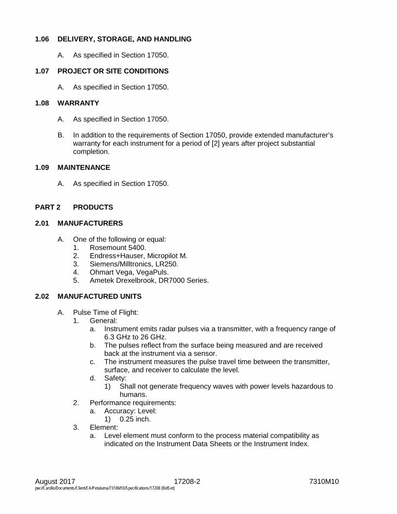
August 2017 17208-2 7310M10 pw://Carollo/Documents/Client/CA/Petaluma/7310M10/Specifications/17208 (BidSet)
1.06 DELIVERY, STORAGE, AND HANDLING
A. As specified in Section 17050.
1.07 PROJECT OR SITE CONDITIONS
A. As specified in Section 17050.
1.08 WARRANTY
A. As specified in Section 17050.
B. In addition to the requirements of Section 17050, provide extended manufacturer’s warranty for each instrument for a period of [2] years after project substantial completion.
1.09 MAINTENANCE
A. As specified in Section 17050.
PART 2 PRODUCTS
2.01 MANUFACTURERS
A. One of the following or equal: 1. Rosemount 5400. 2. Endress+Hauser, Micropilot M. 3. Siemens/Milltronics, LR250. 4. Ohmart Vega, VegaPuls. 5. Ametek Drexelbrook, DR7000 Series.
2.02 MANUFACTURED UNITS
A. Pulse Time of Flight: 1. General:
a. Instrument emits radar pulses via a transmitter, with a frequency range of 6.3 GHz to 26 GHz.
b. The pulses reflect from the surface being measured and are received back at the instrument via a sensor.
c. The instrument measures the pulse travel time between the transmitter, surface, and receiver to calculate the level.
d. Safety: 1) Shall not generate frequency waves with power levels hazardous to
humans. 2. Performance requirements:
a. Accuracy: Level: 1) 0.25 inch.
3. Element: a. Level element must conform to the process material compatibility as
indicated on the Instrument Data Sheets or the Instrument Index.
August 2017 17208-3 7310M10 pw://Carollo/Documents/Client/CA/Petaluma/7310M10/Specifications/17208 (BidSet)
b. Connections: 1) Process: The antenna design shall be suitable for mounting in a
nozzle as indicated on the Instrument Data Sheets or the Instrument Index:
2) The design shall be such that product condensation on the antenna shall not affect the performance of the gauge. It shall be possible to choose between either parabolic-, cone-, rod-shaped antennas.
3) The design shall connect to an existing 8” flange connection. 4. Transmitter:
a. Microprocessor-based signal converter/transmitter. b. Power supply:
1) 24 VDC - 2 wire loop powered. c. Outputs:
1) Isolated 4-20 mA DC with HART communication protocol. d. Backlit digital display for level or volume. e. Self-diagnostics and automatic data checking. f. Signal integrity:
1) Immune to radio frequency and electromagnetic interference with field strength of 15 volts/meter or less over a frequency range of 50 Hz to 460 MHz.
2) Able to ignore momentary level spikes or momentary loss of echo and indicate loss of echo condition on indicating transmitter unit.
g. Protected terminals and fuses in a separate compartment, which isolates field connection from electronics. 1) Indication: Local - 5-digit display.
h. Enclosure rating: NEMA Type 4X. i. Instruments located within hazardous classified areas shall be explosion
proof: 1) Class I, Division 1 and 2, Group A, B, C, and D.
j. Electrical connection: 1/2 inch male NPT.
2.03 ACCESSORIES
A. Software: Provide Windows based PC software for configuration and echo mapping.
B. Provide sun shield for outdoor installations.
2.04 SOURCE QUALITY CONTROL
A. As specified in Section 17050.
B. Factory calibrate each level transmitter at a facility that is traceable to NIST.
C. Provide complete documentation covering the traceability of all calibration instruments.

August 2017 17208-4 7310M10 pw://Carollo/Documents/Client/CA/Petaluma/7310M10/Specifications/17208 (BidSet)
PART 3 EXECUTION
3.01 EXAMINATION (NOT USED)
3.02 PREPARATION (NOT USED)
3.03 INSTALLATION
A. As specified in Section 17050.
B. Coordinate the installation with all trades to ensure that the mechanical system has all necessary appurtenances including weld-o-lets, valves, etc. for proper installation of instruments.
3.04 FIELD QUALITY CONTROL
A. As specified in Section 17050.
3.05 ADJUSTING
A. Verify factory calibration of all instruments in accordance with the manufacturer’s instructions: 1. Return factory calibrated devices to the factory if they do not meet the field
verification requirements for calibration.
3.06 CLEANING
A. As specified in Section 17050.
3.07 DEMONSTRATION AND TRAINING
A. As specified in Section 17050.
B. Demonstrate performance of all instruments to the Engineer before commissioning.
C. Furnish 2 hours of Owner training.
3.08 PROTECTION
A. As specified in Section 17050.
3.09 SCHEDULES
A. The provided information does not necessarily include all required instruments. Provide all instruments identified in the Contract Documents: 1. Instruments may be indicated on the Drawings, specified in the Specifications
or both.
END OF SECTION

August 2017 17208-5 7310M10 pw://Carollo/Documents/Client/CA/Petaluma/7310M10/Specifications/17208 (BidSet)
A/E: Carollo Engineers RADAR PTOF LEVEL INSTRUMENTS
Spec. No. Rev.
Contractor: No
By Date Revision 17208
Project: High Strength Waste Project, 7310M.10 Contract Date
Customer: City of Petaluma Plant: Ellis Creek Water Recycling Facility Req. P.O. Location: Petaluma, CA BOM No.: By Chk App File:
G 1 Instrument Tag Number LE/LIT-15293 LE/LIT-15294
E 2 Service HSW HSW N 3 P&ID 15N03 15N03 4 Other
5 Type Pulse Time of Flight (PTOF)
Pulse Time of Flight (PTOF)
P 6 Housing Material R 7 Measurement Range 0-35 ft 0-35 ft O 8 Op. Temp. Range B 9 Manufacturer E 10 Model 11 Model Number 12 Antenna Style Probe Probe 13 Other 14 Other 15 Other 16 Other
17 Type Pulse Time of Flight (PTOF)
Pulse Time of Flight (PTOF)
T 18 Operating Mode R 19 Enclosure A 20 Mounting Integral Integral N 21 Temperature Range S 22 Voltage Requirements M 23 Power Loop Powered (24 VDC) Loop Powered (24 VDC) I 24 Accuracy ± 0.25 inches ± 0.25 inches T 25 Calibrated Range T 26 Display Multi Character LCD Multi Character LCD E 27 Output 4-20 mA 4-20 mA R 28 Calibration 29 Status Relay 30 Manufacturer 31 Model No. 32 Damping 33 Elect. Entry 34 Other
O 35 P 36 T 37 S 38 Notes: Match existing flange size on HSW storage tank.


August 2017 17302-1 7310M10 pw://Carollo/Documents/Client/CA/Petaluma/7310M10/Specifications/17302 (BidSet)
SECTION 17302
FLOW MEASUREMENT: MAGNETIC FLOWMETERS
PART 1 GENERAL
1.01 SUMMARY
A. Section includes: 1. Full-body magnetic flowmeters.
B. Related sections: 1. Section 01330 - Submittal Procedures. 2. Section 17050 - Common Work Results for Process Control and
Instrumentation Systems.
C. Provide all instruments identified in the Contract Drawings.
1.02 REFERENCES
A. As specified in Section 17050.
B. International Organization for Standardization (ISO): 1. 9000 - Quality management systems -- Fundamentals and vocabulary. 2. 17025 - General requirements for the competence of testing and calibration
laboratories.
C. National Institute of Standards and Technology (NIST).
D. NSF International (NSF).
E. American Association for Laboratory Accreditation (A2LA).
1.03 DEFINITIONS
A. As specified in Section 17050.
1.04 SUBMITTALS
A. Furnish submittals as specified in Sections 01330 and 17050.
1.05 QUALITY ASSURANCE
A. As specified in Section 17050.
B. Examine the complete set of Contract Documents and verify that the instruments are compatible with the installed conditions including: 1. Process conditions: Fluids, pressures, temperatures, flows, materials, etc. 2. Physical conditions:
a. Installation and mounting requirements. b. Location within the process.

August 2017 17302-2 7310M10 pw://Carollo/Documents/Client/CA/Petaluma/7310M10/Specifications/17302 (BidSet)
c. Accessories: Verify that all required accessories are provided and are compatible with the process conditions and physical installation.
C. Notify the Engineer if any installation condition does not meet the instrument manufacturer’s recommendations or specifications.
1.06 DELIVERY, STORAGE, AND HANDLING
A. As specified in Section 17050
1.07 PROJECT OR SITE CONDITIONS
A. As specified in Section 17050.
1.08 WARRANTY
A. As specified in Section 17050.
1.09 MAINTENANCE
A. As specified in Section 17050.
PART 2 PRODUCTS
2.01 MANUFACTURERS
A. One of the following or equal: 1. Endress+Hauser:
a. L or W 400, Promag H100. b. Promag 53.
2. Rosemount: 8750W. 3. Krohne: IFC. 4. Yokogawa: AXF. 5. ABB: Watermaster. 6. Sparling Instruments: TigermagEP Series FM656.
2.02 MANUFACTURED UNITS
A. Magnetic flowmeter: 1. General:
a. Magnetic flowmeters obtain the flow velocity by measuring the changes of induced voltage of the conductive fluid passing across a controlled magnetic field.
b. Complete zero stability shall be an inherent characteristic of the flowmeter system.
c. Include for each magnetic flow metering system: 1) A metering tube with electrodes (sensor). 2) Signal cable. 3) Transmitter integral or remote as indicated on the Drawings. 4) Flowmeter grounding rings.

August 2017 17302-3 7310M10 pw://Carollo/Documents/Client/CA/Petaluma/7310M10/Specifications/17302 (BidSet)
2. Performance requirements: a. Accuracy:
1) 0.25 percent of flow rate from 10 to 100 percent of full scale for velocities ranging between 1.9 to 10 feet per second.
b. Repeatability: 1) 0.25 percent of rate.
3. Element: a. Metering tube:
1) Constructed of carbon steel or Type 304 stainless steel (unless specifically noted otherwise in the instrument data sheets) with flanged connections to match with piping material.
2) Liner material in conformance with: a) Manufacturer’s recommendations for the intended service. b) NSF certified for all drinking water applications.
3) Electrodes type and material in conformance with: a) Manufacturer’s recommendations for the intended service. b) Utilize a minimum of 2, self-cleaning electrodes.
4) Meter terminal housing NEMA Type 4X unless specifically noted otherwise in the instrument data sheets.
5) Meter coating consisting of epoxy painted finish. 6) Components:
a) 2 grounding rings: (1) Which are in conformance with the manufacturer’s bore and
material recommendation for the meter’s intended service. (2) Designed to protect and shield from abrasion of the liner’s
edge interface at the meter’s end. 4. Transmitter:
a. Power supply: 1) 120 VAC. 2) Power consumption: 60 VA maximum.
b. Outputs: 1) As noted in the instrument data sheets. 2) For all instruments with 4 to 20 mA HART or digital bus protocol,
provide a Device Type Manager (DTM) certification by FDT group. c. Microprocessor-based signal converter/transmitter. d. Utilize DC pulse technique to drive flux-producing coils. e. Contain a 6-digit display for flow rate, percent of span, and totalizer. f. Operator keypad interface. g. Integral zero return to provide consistent zero output signals in response
to an external dry contact closure. h. Integral low flow cut-off zero return. i. Programmable parameters including:
1) Meter size. 2) Full-scale flow rate. 3) Magnetic field frequency. 4) Time constant.
j. Data retention for a minimum of 5 years without auxiliary main or battery power.
k. Self-diagnostics and automatic data checking. l. Protected terminals and fuses in a separate compartment which isolates
field connection from electronics.
August 2017 17302-4 7310M10 pw://Carollo/Documents/Client/CA/Petaluma/7310M10/Specifications/17302 (BidSet)
m. Ambient operating temperature limits of -5 to 140 degrees Fahrenheit (-20 to 60 degrees Celsius).
n. The transmitter should retain all setup parameters and accumulated measurements internally in non-volatile memory in the event of power failure.
2.03 ACCESSORIES
A. Stainless steel tag labeled as specified in the Contract Documents.
B. Provide sunshades for all transmitters located outdoors.
C. Provide galvanic isolation gaskets, nylon/Teflon flange bolt insulation bushings and nylon washers on all meters installed on pipes with cathodic protection.
2.04 SOURCE QUALITY CONTROL
A. As specified in Section 17050.
B. Factory calibrate each flow metering system at an ISO-17025 accredited test facility with certified accuracy traceable to NIST.
C. Evidence of accreditation shall originate from a national verification agency such as A2LA.
D. A real-time computer generated printout of the actual calibration date indication actual velocities and as read values of the flow tube. 1. Flow calibration report of the manufacturers flow lab calibration procedure
shall be shipped with the meter system. 2. Minimum calibration shall be a 3 point calibration including 1, 3, and 10 feet
per second velocities for every meter and transmitter system. 3. Manufacturer shall archive all calibration reports for future reference.
PART 3 EXECUTION
3.01 EXAMINATION (NOT USED)
3.02 PREPARATION (NOT USED)
3.03 INSTALLATION
A. As specified in Section 17050.
3.04 FIELD QUALITY CONTROL
A. As specified in Section 17050.
B. Provide manufacturer’s services to perform installation inspection.

August 2017 17302-5 7310M10 pw://Carollo/Documents/Client/CA/Petaluma/7310M10/Specifications/17302 (BidSet)
3.05 ADJUSTING
A. Field Verification: 1. Verify factory calibration of all instruments in accordance with the
manufacturer’s instructions: 2. The transmitter and sensor to include a method to verify flow meter
performance to the original manufacturer specifications. 3. Verification should be traceable to factory calibration using a third party,
attested onboard system pursuant to ISO standards. 4. The verification report should be compliant to common quality systems such
as ISO 9000 to prove reliability of the meter specified accuracy. 5. Return factory calibrated devices to the factory if they do not meet the field
verification requirements for calibration.
3.06 CLEANING
A. As specified in Section 17050.
3.07 DEMONSTRATION AND TRAINING
A. As specified in Section 17050.
B. Demonstrate performance of all instruments to the Engineer before commissioning.
3.08 PROTECTION
A. As specified in Section 17050.
3.09 SCHEDULES
A. Instrument Data Sheets included in this Section.
B. The provided information does not necessarily include all required instruments.
C. Provide all instruments identified in the Contract Documents: 1. Instruments may be indicated on the Drawings, specified in the Specifications,
or both.
END OF SECTION

August 2017 17302-6 7310M10 pw://Carollo/Documents/Client/CA/Petaluma/7310M10/Specifications/17302 (BidSet)
A/E: Carollo Engineers
MAGNETIC FLOWMETERS
INSTRUMENT DATA SHEETS
Spec. No. Rev. Contractor: No By Date Revision 17302
Project: High Strength Waste Project, 7310M.10 Contract Date Customer: City of Petaluma Plant: Ellis Creek Water Recycling Facility Req. P.O. Location: Petaluma, CA BOM No.: By Chk App File:
1 Instrument Tag No. FE/FIT-15193 FE/FIT-17103 2 Service HSW POLYMER 3 P&ID 15N04 17N03 4 C Line Size / Schedule 1.5" 5 O Line Material Mfg Standard
6 N Connection Type/ Pressure Rating
150 PSI
7 N Connection Materials Mfg Standard 8 Tube Size 4"
E 9 Tube Material DIP L 10 Liner Material Mfg Standard E 11 M Electrode Type Mfg Standard Mfg Standard M 12 E Electrode Material E 13 T Meter Casing
N 14 E Power Spply Phase 120
VAC 1P
120 VAC
1P
T 15 R Grounding Type & Matl. 16 Enclosure Class NEMA 4X NEMA 12 17 Other 18 Fluid HSW POLS 19 F Max Flow 150 GPM 12 GPM 20 L Min Velocity 21 U Min Flow Norm Flow 10 50 GPM 22 I Min Temp Max Temp 50 150 23 D Min Press Max Press 20 40 24 Vacuum Possibility 25 Conductivity
T 26 Function R 27 Mounting Integral Integral A 28 Enclosure Class NEMA 4X NEMA 12 N 29 Length Signal Cable S 30 Type Span Adjustment M 31 Power Supply I 32 Transmitter Output 4-20 mA HART Relay Outputs Form C
T 33 Accuracy 0.25% T 34 Calibrated Range E 35 Empty Pipe Detection R 36 Bi-Directional Flow 37 Display Scale Size Range 38 Alarm Contact No. Form 39 Manufacturer 40 Element (Meter) Model No. 41 Transmitter (Inst.) Model No.
Notes:

August 2017 17401-1 7310M10 pw://Carollo/Documents/Client/CA/Petaluma/7310M10/Specifications/17401 (BidSet)
SECTION 17401
PRESSURE/VACUUM MEASUREMENT: DIAPHRAGM AND ANNULAR SEALS
PART 1 GENERAL
1.01 SUMMARY
A. Section includes: 1. Diaphragm seals. 2. Annular seals.
B. Related sections: 1. Section 01330 - Submittal Procedures. 2. Section 17050 - Common Work Results for Process Control and
Instrumentation Systems.
C. Provide all seals identified in the Contract Documents.
1.02 REFERENCES
A. As specified in Section 17050.
1.03 DEFINITIONS
A. As specified in Section 17050.
1.04 SUBMITTALS
A. Furnish submittals as specified in Sections 01330 and 17050.
B. Additional requirements: 1. Product data:
a. Manufacturer’s installation instructions. b. Seal type. c. Body materials. d. Diaphragm material. e. Fill fluid type. f. Seal size. g. Options. h. Process connection.
1.05 QUALITY ASSURANCE
A. As specified in Section 17050.
B. Examine the complete set of Contract Documents and verify the compatibility with the installed conditions including: 1. Process conditions: Fluids, pressures, temperatures, flows, materials, etc. 2. Physical conditions:
a. Installation and mounting requirements.

August 2017 17401-2 7310M10 pw://Carollo/Documents/Client/CA/Petaluma/7310M10/Specifications/17401 (BidSet)
b. Location within the process. c. Accessories: Verify that all required accessories are provided and are
compatible with the process conditions and physical installation.
C. Notify the Engineer if any installation condition does not meet the manufacturer’s recommendations or specifications.
1.06 DELIVERY, STORAGE, AND HANDLING
A. As specified in Section 17050.
1.07 PROJECT OR SITE CONDITIONS
A. As specified in Section 17050.
1.08 WARRANTY
A. As specified in Section 17050.
1.09 MAINTENANCE
A. As specified in Section 17050.
B. Provide spare annular seal for every size indicated in the project.
PART 2 PRODUCTS
2.01 MANUFACTURERS
A. Diaphragm seals: 1. For chemical applications, liquids containing solids, and liquids with pulsating
flow having pressures less than or equal to 15 pounds per square inch gauge: One of the following or equal: a. Ashcroft:
1) Flushing connection: Type 741. 2) Without flushing connection: Type 740.
b. Mansfield and Green: 1) Flushing connection: Type SGT. 2) Without flushing connection: Type SBT.
c. Wika, Type L990.40. d. Rosemount.
2. For chemical applications, liquids containing solids, and liquids with pulsating flow having pressures greater than or equal to 15 pounds per square inch gauge: One of the following or equal: a. Ashcroft:
1) Flushing connection: Type 201. 2) Without flushing connection: Type 200. 3) Saddle mount: Type 205.
b. Mansfield and Green: 1) Flushing connection: Type SG. 2) Without flushing connection: Type SB. 3) Saddle mount: Type SJ.

August 2017 17401-3 7310M10 pw://Carollo/Documents/Client/CA/Petaluma/7310M10/Specifications/17401 (BidSet)
c. Wika: 1) Type L990.10. 2) Saddle mount: L910.ZA.
d. Rosemount.
B. Annular seals: 1. One of the following or equal:
a. Ashcroft Iso-Ring. b. Onyx Valve. c. Red Valve.
2.02 MANUFACTURED UNITS
A. Diaphragm seals: 1. General:
a. Diaphragm seal and pressure instrument shall be assembled by pressure instrument manufacturer and shipped as an assembly.
2. Requirements: a. Seal type:
1) Metallic diaphragm: Welded to upper housing. 2) Elastomer diaphragm: Bonded to upper housing.
b. Process connection: Saddle flange. c. Instrument connection: 1/2 inch NPT. d. Material Construction: Type 316 Stainless Steel. e. Provide 1/4-inch flushing connection in diaphragm lower housing or
provide flushing ring. f. Flush port plug: Same material of construction as diaphragm lower
housing. g. Provide fill/bleed connection. h. Mounting: As indicated in the Contract Documents. i. Provide Type 316 stainless steel armored capillary for all remote
installations. j. Nuts and bolts: Type 316 stainless steel. k. Materials of construction:
1) Sewage, sludge, liquids containing solids, and liquids with pulsating flow having pressures less than or equal to 15 pounds per square inch: a) Diaphragm: Type 316 stainless steel. b) Lower housing: Type 316 stainless steel. c) Upper housing: Manufacturer’s standard. d) Fill fluid: Silicon oil.
2) Sewage, sludge, liquids containing solids, and liquids with pulsating flow having pressures greater than 15 pounds per square inch: a) Diaphragm: Type 316 stainless steel. b) Lower housing: Type 316 stainless steel. c) Upper housing: Manufacturer’s standard. d) Fill fluid: Silicon oil.
B. Annular seals: 1. General:
a. Inside diameter of annular seal shall provide uninterrupted flow: 1) There shall be no dead ends or crevices.

August 2017 17401-4 7310M10 pw://Carollo/Documents/Client/CA/Petaluma/7310M10/Specifications/17401 (BidSet)
2) Process flow shall be sufficient to make the annular seal self-cleaning.
b. The pressure sensing flexible cylinder shall measure pressure around the full inside circumference of the pipeline.
2. Requirements: a. Pressure rating: Equivalent to the ANSI flanges. b. Materials of construction:
1) Inner flexible cylinder: Manufacturer’s standard. 2) Body:
a) Carbon Steel with epoxy coating. 3) Assembly flanges: To match adjacent piping. 4) Fill fluid: Silicon oil.
c. Nominal pipe size: As indicated on the Drawings. d. Process connection: Class 150 Raised Face Flange e. Instrument connection: 1/2 inch NPT. f. Provide isolating needle valve between annular seal and pressure
instrument.
2.03 ACCESSORIES
A. Provide field fill kits.
2.04 SOURCE QUALITY CONTROL
A. As specified in Section 17050.
PART 3 EXECUTION
3.01 EXAMINATION (NOT USED)
3.02 PREPARATION (NOT USED)
3.03 INSTALLATION
A. As specified in Section 17050.
B. Coordinate the installation with all trades to ensure that the mechanical system has all necessary appurtenances including weld-o-lets, valves, etc. for proper installation of instruments.
C. Do not use Teflon thread seal tape on pressure instruments with silicon oil fill fluid.
3.04 FIELD QUALITY CONTROL
A. As specified in Section 17050.
3.05 ADJUSTING (NOT USED)
3.06 CLEANING
A. As specified in Section 17050.

August 2017 17401-5 7310M10 pw://Carollo/Documents/Client/CA/Petaluma/7310M10/Specifications/17401 (BidSet)
3.07 DEMONSTRATION AND TRAINING
A. As specified in Section 17050.
3.08 PROTECTION
A. As specified in Section 17050.
3.09 SCHEDULES (NOT USED)
END OF SECTION


August 2017 17402-1 7310M10 pw://Carollo/Documents/Client/CA/Petaluma/7310M10/Specifications/17402 (BidSet)
SECTION 17402
PRESSURE/VACUUM MEASUREMENT: INSTRUMENT VALVES
PART 1 GENERAL
1.01 SUMMARY
A. Section includes: 1. Valve manifolds and instrument valves.
B. Related sections: 1. Section 01330 - Submittal Procedures. 2. Section 17050 - Common Work Results for Process Control and
Instrumentation Systems.
C. Provide all valves identified in the Contract Documents.
1.02 REFERENCES
A. As specified in Section 17050.
1.03 DEFINITIONS
A. As specified in Section 17050.
1.04 SUBMITTALS
A. Furnish submittals as specified in Sections 01330 and 17050.
B. Additional requirements: 1. Product data:
a. Valve type. b. Body material. c. Size. d. Options.
2. Shop drawings: a. Mounting details for all manifold valves.
1.05 QUALITY ASSURANCE
A. As specified in Section 17050.
B. Examine the complete set of Contract Documents and verify that the valves are compatible with the installed conditions including: 1. Process conditions: Fluids, pressures, temperatures, flows, materials, etc. 2. Physical conditions:
a. Installation and mounting requirements. b. Location within the process. c. Accessories: Verify that all required accessories are provided and are
compatible with the process conditions and physical installation.

August 2017 17402-2 7310M10 pw://Carollo/Documents/Client/CA/Petaluma/7310M10/Specifications/17402 (BidSet)
C. Notify the Engineer if any installation condition does not meet the valve manufacturer’s recommendations or specifications.
D. Provide valves manufactured at facilities certified to the quality standards of ISO 9001.
1.06 DELIVERY, STORAGE, AND HANDLING
A. As specified in Section 17050.
B. Protect valve manifolds and protective coatings from damage during handling and installation. Repair coating where damaged.
1.07 PROJECT OR SITE CONDITIONS
A. Project environmental conditions as specified in Section 17050. 1. Provide valves suitable for the installed site conditions including, but not
limited to, material compatibility, process, and ambient temperatures.
1.08 WARRANTY
A. As specified in Section 17050.
1.09 MAINTENANCE
A. As specified in Section 17050.
B. Furnish all parts, materials, fluids, etc. necessary for operation, maintenance, and calibration purposes throughout the warranty period. Deliver all of these supplies before project substantial completion.
PART 2 PRODUCTS
2.01 MANUFACTURERS
A. Valve manifold manufacturers: One of the following or equal: 1. Anderson Greenwood. 2. Hex Valve. 3. Noshok. 4. Rosemount.
B. Block and bleed valve manufacturers: One of the following, no equal: 1. Varec.
C. Gauge valve manufacturers: One of the following or equal: 1. Anderson Greenwood. 2. Hex Valve.
D. Level sensor isolation valve manufacturers: One of the following or equal: 1. Indu-Tech Level Sensor Isolation Valve. 2. DeZURIK Level Sensor Isolation Valve. 3. Tyco Rovalve Isolation Knife Gate Valve.

August 2017 17402-3 7310M10 pw://Carollo/Documents/Client/CA/Petaluma/7310M10/Specifications/17402 (BidSet)
2.02 MANUFACTURED UNITS
A. Valve manifolds: 1. General:
a. Provide 2-valve, 3-valve, blowdown type 5-valve, or metering type 5-valve manifolds as indicated on the Drawings.
b. Valve manifolds shall have one piece bonnet with a metal to metal seal to the valve body below the bonnet threads.
2. Requirements: a. Bonnet lock pin to prevent accidental loosening. b. Gas leak tested metal-to-metal hard seat design for hard seat valves. c. Gas leak tested soft seat design with replaceable seat for soft seat valves. d. Manifold valves shall have straight through portion for bi-directional flow
and easy roddable cleaning. e. Manifold valves shall allow for direct or remote instrument mounting. f. Shall be able to withstand pressures up to 6,000 psi for soft seat valves
and 10,000 psi for hard seat valves at maximum 200 degrees Fahrenheit. g. Materials of construction:
1) Body material: Type 316 stainless steel. 2) O-Ring: Teflon.
h. 2-Valve manifolds: 1) 1 isolation valve and 1 drain/vent and calibration valve.
i. 3-Valve manifolds: 1) 2 isolation valves and 1 equalizing valve for differential pressure
applications. 2) Plugged vent connections used for vent/drain or calibration.
j. Blowdown 5-valve manifold: 1) 2 isolation valves, 1 equalizing valve, 2 blowdown valves for
differential pressure applications. k. Metering 5-valve manifold:
1) 2 isolation valves, 2 equalizing valves, 1 vent/drain and calibration valve for differential pressure applications.
B. Block and bleed valves: 1. General:
a. Valve shall provide process isolation and venting/draining capabilities. b. Gas leak tested metal-to-metal hard seat design for hard seat valves. c. Gas leak tested soft seat design with replaceable seat for soft seat valves. d. Valve shall not be used with fluids with high solids content, such as raw
wastewater or sludge. 2. Requirements:
a. Materials of construction: 1) Body material: Type 316 stainless steel. 2) O-Ring: Teflon.
C. Gauge valves: 1. General:
a. Valve shall provide process isolation from pressure instrument. b. Gas leak tested, metal-to-metal hard seat design for hard seat valves. c. Gas leak tested soft seat design with replaceable seat for soft seat valves.

August 2017 17402-4 7310M10 pw://Carollo/Documents/Client/CA/Petaluma/7310M10/Specifications/17402 (BidSet)
2. Requirements: a. Materials of construction:
1) Body material: Type 316 stainless steel. 2) O-Ring: Teflon.
D. Level sensor isolation valves: 1. General:
a. Valve shall provide process isolation from level diaphragm. b. Gas leak tested, metal-to-metal hard seat design for hard seat valves. c. Gas leak tested soft seat design with replaceable seat for soft seat valves.
2. Requirements: a. Materials of construction:
1) Body material: Type 316 stainless steel. 2) Flange diameter size: as indicated on Drawings.
2.03 ACCESSORIES
A. Provide tube fitting, female NPT, or pipe butt weld connections if necessary.
B. Provide stainless steel concentric or eccentric pipe nipples when necessary.
2.04 SOURCE QUALITY CONTROL
A. As specified in Section 17050.
PART 3 EXECUTION
3.01 EXAMINATION
A. Examine the installation location and verify it will work properly when installed. 1. Notify the Engineer promptly if any installation condition does not meet the
manufacturer’s recommendations or specifications.
3.02 PREPARATION (NOT USED)
3.03 INSTALLATION
A. As specified in Section 17050.
B. Coordinate the installation with all trades to ensure that the mechanical system has all necessary appurtenances including weld-o-lets, valves, etc. for proper installation of all valves.
3.04 FIELD QUALITY CONTROL
A. As specified in Section 17050.
3.05 ADJUSTING
A. As specified in Section 17950.
August 2017 17402-5 7310M10 pw://Carollo/Documents/Client/CA/Petaluma/7310M10/Specifications/17402 (BidSet)
3.06 CLEANING
A. As specified in Section 17050.
3.07 DEMONSTRATION AND TRAINING
A. As specified in Section 17050.
B. Demonstrate performance of all valves to the Engineer before commissioning.
3.08 PROTECTION
A. As specified in Section 17050.
3.09 SCHEDULES (NOT USED)
END OF SECTION


August 2017 17403-1 7310M10 pw://Carollo/Documents/Client/CA/Petaluma/7310M10/Specifications/17403 (BidSet)
SECTION 17403
PRESSURE/VACUUM MEASUREMENT: SWITCHES
PART 1 GENERAL
1.01 SUMMARY
A. Section includes: 1. Pressure/vacuum switches.
B. Related sections: 1. Section 01330 - Submittal Procedures. 2. Section 17050 - Common Work Results for Process Control and
Instrumentation Systems. 3. Section 17401 - Pressure/Vacuum Measurement: Diaphragm and Annular
Seals. 4. Section 17402 - Pressure/Vacuum Measurement: Instrument Valves.
C. Provide all instruments specified in the Contract Documents.
1.02 REFERENCES
A. As specified in Section 17050.
1.03 DEFINITIONS
A. As specified in Section 17050.
1.04 SUBMITTALS
A. Furnish submittals as specified in Sections 01330 and 17050.
B. Additional requirements: 1. Product data:
a. Accessories such as diaphragm seals, valve manifold, snubbers, and pulsation dampeners.
1.05 QUALITY ASSURANCE
A. As specified in Section 17050.
B. Examine the complete set of Contract Documents and verify that the instruments are compatible with the installed conditions including: 1. Process conditions: Fluids, pressures, temperatures, flows, materials, etc. 2. Physical conditions:
a. Installation and mounting requirements. b. Location within the process. c. Accessories: Verify that all required accessories are provided and are
compatible with the process conditions and physical installation.

August 2017 17403-2 7310M10 pw://Carollo/Documents/Client/CA/Petaluma/7310M10/Specifications/17403 (BidSet)
C. Notify the Engineer if any installation condition does not meet the instrument manufacturer’s recommendations or specifications.
1.06 DELIVERY, STORAGE, AND HANDLING
A. As specified in Section 17050.
1.07 PROJECT OR SITE CONDITIONS
A. Project environmental conditions as specified in Section 17050. 1. Provide instruments suitable for the installed site conditions including, but not
limited to, material compatibility, site altitude, site seismic conditions, humidity, and process and ambient temperatures.
1.08 WARRANTY
A. As specified in Section 17050.
1.09 MAINTENANCE
A. Furnish all parts, materials, fluids, etc. necessary for operation, maintenance, and calibration purposes throughout the warranty period. Deliver all of these supplies before project substantial completion.
PART 2 PRODUCTS
2.01 MANUFACTURERS
A. Mechanical type pressure switch: One of the following, no equal: 1. Ashcroft B Series Type 400. 2. United Electric Controls 400Series.
B. Electronic type pressure switch: One of the following, no equal: 1. Ashcroft N Series. 2. United Electric Series One.
2.02 MANUFACTURED UNITS
A. Mechanical type pressure switches: 1. General:
a. Pressure switch shall be diaphragm or diaphragm-sealed piston type. 2. Performance requirements:
a. Pressure range: 1) As specified in data sheets following this Section.
b. Accuracy: 1) Within 1.0 percent of range.
c. Repeatability: 1) Within 1.0 percent of range.
3. Element: a. Type: Diaphragm, diaphragm-sealed piston, or bourdon tube.

August 2017 17403-3 7310M10 pw://Carollo/Documents/Client/CA/Petaluma/7310M10/Specifications/17403 (BidSet)
b. Overpressure: 1) Minimum 130 percent of maximum range pressure without damage
to switch or sensing element. 2) Minimum 400 percent of nominal range without leakage or rupture.
c. Sensing element shall not require ambient temperature compensation. d. Wetted materials: Stainless steel e. Setpoint:
1) Single. 2) Switch shall activate at setpoint on increasing pressure for high-
pressure alarm applications and on decreasing pressure for low-pressure alarm applications.
f. Adjustable deadband. g. Switch elements:
1) Snap acting. 2) Single pole-double throw (SPDT). 3) Rated at 10 A, 125/250 VAC. 4) Automatic reset type, where indicated on the Drawings. 5) Manual reset type where indicated on the Drawings.
h. Enclosure: Epoxy coated: 1) NEMA Type 4. 2) NEMA Type 4X. 3) NEMA Type 7.
i. Switch mounting: 1) Process connection: 1/2-inch NPT.
4. Components: a. Provide all necessary hardware for pressure switch mounting.
2.03 ACCESSORIES
A. Pulsation dampeners and snubbers: 1. Provide pulsation dampener or snubber with each pressure switch installed on
discharge of positive displacement type pump. 2. Materials: Stainless steel. 3. Mount pulsation dampener or snubber integrally to the pressure switch. 4. Connection: as indicated on the Drawings.
B. Provide diaphragm seals as specified in data sheets or as indicated on the Drawings and as specified in Section 17401: 1. Diaphragm seal and pressure switch shall be assembled by manufacturer and
shipped as an assembly.
C. Furnish gauge valves as specified in Section 17402.
2.04 SOURCE QUALITY CONTROL
A. As specified in Section 17050.
B. Factory calibrate each instrument with a minimum 3-point calibration or according to Manufacturer’s standard at a facility that is traceable to the NIST. 1. Submit calibration data sheets to the Engineer at least 30 days before
shipment of the instruments to the project site.

August 2017 17403-4 7310M10 pw://Carollo/Documents/Client/CA/Petaluma/7310M10/Specifications/17403 (BidSet)
PART 3 EXECUTION
3.01 EXAMINATION (NOT USED)
3.02 PREPARATION (NOT USED)
3.03 INSTALLATION
A. As specified in Section 17050.
B. Coordinate the installation with all trades to ensure that the mechanical system has all necessary appurtenances including weld-o-lets, valves, etc. for proper installation of instruments.
3.04 FIELD QUALITY CONTROL
A. As specified in Section 17050.
3.05 ADJUSTING
A. Verify factory calibration of all instruments in accordance with the manufacturer’s instructions: 1. Return factory calibrated devices to the factory if they do not meet the field
verification requirements for calibration.
3.06 CLEANING
A. As specified in Section 17050.
3.07 DEMONSTRATION AND TRAINING
A. As specified in Section 17050.
3.08 PROTECTION
A. As specified in Section 17050.
3.09 SCHEDULES
A. The provided information does not necessarily include all required instruments. Provide all instruments specified in the Contract Documents: 1. Instruments may be indicated on the Drawings, specified in the Specifications
or both.
END OF SECTION

August 2017 17403-5 7310M10 pw://Carollo/Documents/Client/CA/Petaluma/7310M10/Specifications/17403 (BidSet)
A/E: Carollo Engineers PRESSURE/VACUUM
SWITCHES
Spec. No. Rev. Contractor: No By Date Revision 17403
Project: High Strength Waste Project, 7310M.10
Contract Date
Customer: City of Petaluma Plant: Ellis Creek Water Recycling Facility Req. P.O. Location: Petaluma, CA BOM No.: By Chk App File:
1 Type Press: X Vacuum: Comp.: Diff.Press: Other D 2 Setting Set in Field: Factory Set: Internal: External: Dial: E 3 Dead Band Fixed: Adj.: x Min.: Other: V 4 Mtl : Body Seat Tube
I 5 Element Type Diaphragm: Bourdon: Bellows: Other
C 6 Material Bronze: SS: Alloy St.: Other E 7 Connection ½ in NPT Bottom: Back: 8 Mounting Local: Surface: Flush: 9 Accuracy 10 Other 11 Type Mercury: Snap: X Other 12 Quantity Single: X Dual: Other
S 13 Form SPST: X SPDT: DPDT: Other W 14 Rating: Amps Volts Hertz 10 120 60 I 15 Other T 16 Load Inductive: Non-Inductive: C 17 Enclosure General Purpose: X Weatherproof: None: Explosion proof: H 18 Enclosure Class 19 Conduit Connection MFR STD: X Other 20 Other 21 Manufacturer 22 Model No.
Rev Tag Number Adj. Range SP Process Signal SP Op. Temp. P&ID Service Notes PSL-15291A 0-7 PSIG 1 PSIG 15N02 HSW PSH-15291B 0-20 PSIG 20 PSIG 15N02 HSW PSL-15292A 0-7 PSIG 1 PSIG 15N02 HSW PSH-15292B 0-20 PSIG 20 PSIG 15N02 HSW PSL-15195A 0-15 PSIG 1 PSIG 15N04 HSW PSH-15195B 0-20 PSIG 20 PSIG 15N04 HSW PSL-15295A 0-15 PSIG 1 PSIG 15N04 HSW PSH-15295B 0-20 PSIG 20 PSIG 15N04 HSW Notes: Refer to Section 17401 for additional diaphragm seal requirements. Refer to Section 17402 for additional instrument valve requirements. High pressure switches shall activate at setpoint on increasing pressure. Low pressure switches shall activate at setpoint on decreasing pressure.


August 2017 17404-1 7310M10 pw://Carollo/Documents/Client/CA/Petaluma/7310M10/Specifications/17404 (BidSet)
SECTION 17404
PRESSURE/VACUUM MEASUREMENT: GAUGES
PART 1 GENERAL
1.01 SUMMARY
A. Section includes: 1. Pressure/vacuum gauges.
B. Related sections: 1. Section 01330 - Submittal Procedures. 2. Section 17050 - Common Work Results for Process Control and
Instrumentation Systems. 3. Section 17401 - Pressure/Vacuum Measurement: Diaphragm and Annular
Seals. 4. Section 17402 - Pressure/Vacuum Measurement: Instrument Valves.
C. Provide all instruments specified in the Contract Documents.
1.02 REFERENCES
A. As specified in Section 17050.
B. American Society of Mechanical Engineers (ASME): 1. B40.100 - Pressure Gauges and Gauge Attachments.
1.03 DEFINITIONS
A. As specified in Section 17050.
1.04 SUBMITTALS
A. Furnish submittals as specified in Sections 01330 and 17050.
B. Additional requirements: 1. Product data:
a. Accessories such as diaphragm seals, valve manifold, snubbers, and pulsation dampeners.
1.05 QUALITY ASSURANCE
A. As specified in Section 17050.
B. Examine the complete set of Contract Documents and verify that the instruments are compatible with the installed conditions including: 1. Process conditions: Fluids, pressures, temperatures, flows, materials, etc. 2. Physical conditions:
a. Installation and mounting requirements. b. Location within the process.

August 2017 17404-2 7310M10 pw://Carollo/Documents/Client/CA/Petaluma/7310M10/Specifications/17404 (BidSet)
c. Accessories: Verify that all required accessories are provided and are compatible with the process conditions and physical installation.
C. Notify the Engineer if any installation condition does not meet the instrument manufacturer’s recommendations or specifications.
1.06 DELIVERY, STORAGE, AND HANDLING
A. As specified in Section 17050.
1.07 PROJECT OR SITE CONDITIONS
A. As specified in Section 17050.
1.08 WARRANTY
A. As specified in Section 17050.
1.09 MAINTENANCE
A. As specified in Section 17050.
PART 2 PRODUCTS
2.01 MANUFACTURERS
A. Manufacturers: One of the following or equal: 1. Ashcroft:
a. Maximum pressure less than 10 pounds per square inch: Model1189. b. Maximum pressure greater than or equal to 10 pounds per square inch:
Model 1279 2. Wika. 3. Ametek U.S. Gauge.
2.02 MANUFACTURED UNITS
A. General: 1. Pressure gauge assembly shall include pressure sensing element, gauge
case, and dial mechanism.
B. Performance requirements: 1. Pressure range:
a. As specified in the Contract Documents. 2. Accuracy:
a. Grade 2A, as defined by ASME B40.100. b. Within 1.0 percent of span after friction errors are eliminated by tapping or
vibration. c. Maximum allowable friction inaccuracy: Within 1.0 percent of span.
3. Element: a. Where the maximum pressure is less than 10 pounds per square inch,
provide socket and bellows; for all other pressure ranges, employ a Bourdon tube.

August 2017 17404-3 7310M10 pw://Carollo/Documents/Client/CA/Petaluma/7310M10/Specifications/17404 (BidSet)
b. Socket tips for bellows and Bourdon tube: 1) Materials: Type 316 stainless steel.
c. Overpressure: Minimum 130 percent of maximum range pressure without damage to gauge or sensing element.
d. Wetted materials: Type 316 stainless steel. 4. Dial gauge:
a. Dial size: 4-1/2 inches. b. Dial case material: c. Maximum pressure less than 10 pounds per square inch:
1) Aluminum. d. Maximum pressure greater than or equal to 10 pounds per square inch:
1) Phenolic e. Provide safety gauge with safety blow out through the back or top of the
unit. f. Dial face: Gasketed shatterproof glass or polycarbonate. g. Provide gauge locks on all pressure gauges directly connected to
diaphragm seals. h. Provide gauge locks where possible. i. Connection and mounting:
1) Direct mounted and suitable for outdoor installation. 2) 1/2 inch NPT. 3) Connection material: Stainless steel.
j. Pointer: Externally adjustable.
2.03 ACCESSORIES
A. Pulsation dampeners and snubbers: 1. Provide pulsation dampener or snubber with each pressure gauge installed on
discharge of positive displacement type pump. 2. Provide piston-type snubber if pressure spikes will exceed 130 percent of
gauge maximum range. 3. Materials: Type 316 stainless steel. 4. Mount pulsation dampener or snubber integrally to the pressure gauge. 5. Connection: 1/2-inch NPT.
B. Provide diaphragm seals as specified in the Contract Documents and in Section 17401: 1. Diaphragm seal and pressure gauge shall be assembled by manufacturer and
shipped as an assembly.
C. Provide means for gauge isolation as specified in Section 17402: 1. Mount valve manifold integrally to the gauge. 2. Valve manifold and pressure gauge shall be assembled by manufacturer and
shipped as an assembly.
2.04 SOURCE QUALITY CONTROL
A. As specified in Section 17050.
B. Factory calibrate each pressure gauge at a facility that is traceable to the NIST.
C. Provide complete documentation covering the traceability of all calibration instruments.

August 2017 17404-4 7310M10 pw://Carollo/Documents/Client/CA/Petaluma/7310M10/Specifications/17404 (BidSet)
PART 3 EXECUTION
3.01 EXAMINATION (NOT USED)
3.02 PREPARATION (NOT USED)
3.03 INSTALLATION
A. As specified in Section 17050.
B. Coordinate the installation with all trades to ensure that the mechanical system has all necessary appurtenances including weld-o-lets, valves, etc. for proper installation of instruments.
3.04 FIELD QUALITY CONTROL
A. As specified in Section 17050.
3.05 ADJUSTING
A. Verify factory calibration of all instruments in accordance with the manufacturer’s instructions: 1. Return factory calibrated devices to the factory if they do not meet the field
verification requirements for calibration.
3.06 CLEANING
A. As specified in Section 17050.
3.07 DEMONSTRATION AND TRAINING
A. As specified in Section 17050.
3.08 PROTECTION
A. As specified in Section 17050.
3.09 SCHEDULES
A. The provided information does not necessarily include all required instruments. Provide all instruments identified in the Contract Documents: 1. Instruments may be indicated on the Drawings, specified in the Specifications
or both.
END OF SECTION

August 2017 17404-5 7310M10 pw://Carollo/Documents/Client/CA/Petaluma/7310M10/Specifications/17404 (BidSet)
A/E: Carollo Engineers PRESSURE GAUGES
Spec. No. Rev. Contractor: No By Date Revision 17404 Project: High Strength Waste Project, 7310M.10 Contract Date Customer: City of Petaluma Plant: Ellis Creek Water Recycling Facility Req. P.O. Location: Petaluma, CA BOM No.: By Chk App File: 1 Type Direct Rdg.: √ Receiver: Other: 2 Mounting Surface: Local: Flush: 3 Dial Diameter: 4.5” Color: 4 Case Cast Iron: Aluminum: Phenolic: √ Polished SS Other: 5 Ring Screwed: Hinged: Slip: Std: Other: 6 Blowout Protection None: Disc: Front: Other: Mfr. Std. 7 Lens Glass: √ Plastic: 8 Options Siphon: N/A Material: 9 Other Snubber:
10 Other Pressure Limit Valve: N/A 11 Other Movement Damping: N/A 12 Nominal Accuracy Required 13 Pressure Element Bourdon: √ Bellows: Other: 14 Element Material Bronze: Steel: Type SS: 316 √ Other: 15 Socket Material Bronze: Steel: SS: 316 Other: 16 Connection ¼ in.: ½ in.: √ Bottom: Other: 17 Movement Dampened: Standard: √ Other: 18 Diaphragm Seal Mfr.: Wetted Part Mat’l: Type: 19 Other Other Mat’l: Fill Fluid: Model: 20 Manufacturer 21 Model No. Rev Tag Number Range P&ID Service Notes
PI-01237 0-15 PSIG 01N01 Grit PI-15291A 0-10 PSIG 15N02 High Strength Waste PI-15291B 0-25 PSIG 15N02 High Strength Waste PI-15292A 0-10 PSIG 15N02 High Strength Waste PI-15292B 0-25 PSIG 15N02 High Strength Waste PI-15195A 0-15 PSIG 15N04 High Strength Waste PI-15195B 0-25 PSIG 15N04 High Strength Waste PI-15295A 0-15 PSIG 15N04 High Strength Waste PI-15295B 0-25 PSIG 15N04 High Strength Waste
Notes: Refer to Section 17402 for additional instrument valve requirements.


August 2017 17710-1 7310M10 pw://Carollo/Documents/Client/CA/Petaluma/7310M10/Specifications/17710 (BidSet)
SECTION 17710
CONTROL SYSTEMS: PANELS, ENCLOSURES, AND PANEL COMPONENTS
PART 1 GENERAL
1.01 SUMMARY
A. Section includes: 1. Design, fabrication and assembly of all instrumentation enclosures, control
panels and components provided under this contract, including but not limited to: a. Custom built instrumentation and control panels, including all enclosures
for hand stations controllers, low voltage power distribution and marshalling panels.
b. Control panels furnished as part of equipment systems specified in other Divisions, such as vendor control panels (VCPs) and chemical feed panels.
c. Control components. d. Control panel installation.
B. Related sections: 1. Section 01330 - Submittal Procedures. 2. Section 01612 - Seismic Design Criteria. 3. Section 16050 - Common Work Results for Electrical. 4. Section 16075 - Identification for Electrical Systems. 5. Section 16262 - Variable Frequency Drives 0.50 - 50 Horsepower. 6. Section 16412 - Low Voltage Molded Case Circuit Breakers. 7. Section 16422 - Motor Starters. 8. Section 17050 - Common Work Results for Process Control and
Instrumentation Systems.
C. Provide all control panels identified in Contract Documents.
1.02 REFERENCES
A. As specified in Section 17050.
B. Institute of Electrical and Electronics Engineers (IEEE): 1. C62.41.1 - Guide on the Surge Environment in Low-Voltage (1000 V and less)
AC Power Circuits.
C. Underwriters Laboratories Inc. (UL): 1. 508 - Standard for Industrial Control Equipment. 2. 508A - Standard for Industrial Control Panel. 3. 1283 - Standard for Electromagnetic Interference Filters. 4. 1449 - Standard for Surge Protective Devices.
1.03 DEFINITIONS
A. As specified in Section 17050.

August 2017 17710-2 7310M10 pw://Carollo/Documents/Client/CA/Petaluma/7310M10/Specifications/17710 (BidSet)
B. Specific definitions: 1. The term “panel” in this Section is interchangeable with the term “enclosure.”
1.04 SYSTEM DESCRIPTION
A. Panel dimensions: 1. Minimum dimensions are scalable from or as indicated on the Drawings and
are based upon manufacturer’s non-certified information. It is the responsibility of the Contractor or manufacturer to design and size all panels: a. Size panels to provide space for all equipment, wiring, terminations, and
other items in the panel, including space for future build out. b. Panel sizes that substantially deviate (within 3 inches in any dimension)
from the sizes indicated on the Drawings must be approved by the Engineer.
c. Maximum panel depth: 30 inches, unless otherwise indicated.
B. Structural design: 1. Completed and installed panel work shall safely withstand seismic
requirements at the project site as specified in Section 16050. Enclosures and internal equipment shall be braced to prevent damage from specified forces.
1.05 SUBMITTALS
A. Provide submittals as specified in Sections 01330 and 17050.
B. Provide a control panel hardware submittal for each control panel and enclosure being provided on this project, including but not limited to: 1. Product data:
a. Enclosure construction details and NEMA type. b. Manufacturer's literature and specification data sheets for each type of
equipment to be installed within or on the panel or enclosure. 2. Shop drawings:
a. Scaled, detailed exterior panel (front and side views) and interior panel layout showing equipment arrangement and dimensional information: 1) Provide draft for review and approval by Engineer. The Engineer has
the authority to substantially alter initial panel layouts. b. Complete nameplate engraving schedule. c. Structural details of fabricated panels.
3. Calculations: a. Provide installation details based on calculated shear and tension forces:
1) Calculations shall be signed and sealed by a Professional Engineer licensed in the state where the cabinets and panels will be installed.
b. For assembled enclosures and other equipment with a weight of 200 pounds or more, provide calculations for: 1) Weight including panel internal components. 2) Seismic forces and overturning moments. 3) Shear and tension forces in connections.
c. Cooling calculations, including but not limited to: 1) Highest expected ambient temperature for the enclosure's location. 2) Internal heat load. 3) Exposure to direct sunlight. 4) Dimensions of the enclosure in inches.

August 2017 17710-3 7310M10 pw://Carollo/Documents/Client/CA/Petaluma/7310M10/Specifications/17710 (BidSet)
5) Maximum allowable temperature inside the enclosure, based on the lowest operating temperature limit of the installed components.
C. Seismic design: 1. Seismic panel construction:
a. Seismic anchorage: Provide seismic design calculations and installation details for anchorage of all panels, enclosures, consoles, etc. to meet seismic requirements in Section 01612: 1) Stamped by a Professional Engineer registered in the state where
the project is being constructed. b. For floor-mounted freestanding panels weighing 200 pounds or more
(assembled, including contents), submit calculations, data sheets, and other information to substantiate that panel, base, and framing meet minimum design strength requirements and seismic requirements as specified in Section 01612. Calculations shall be signed and sealed by a Professional Engineer licensed in the state where the cabinets and panels will be installed.
1.06 QUALITY ASSURANCE
A. As specified in Section 17050.
B. Assemble panels, enclosures, and rack systems along with all internal and external devices, wiring, equipment, and materials in a facility that is recognized by UL to assemble and certify UL-labeled control panels: 1. Provide all components and equipment with UL 508 listing. 2. All control panels shall be UL 508A labeled, unless the equipment in the panel
and the design in the contract documents cannot be reasonably modified to meet the requirements for UL 508A labeling:
3. Provide fuses for all equipment that is not UL or UR listed.
1.07 DELIVERY, STORAGE, AND HANDLING
A. Project environmental conditions as specified in Section 17050. 1. Provide instruments suitable for the installed site conditions including, but not
limited to, material compatibility, site altitude, site seismic conditions, humidity, and process and ambient temperatures.
1.08 PROJECT OR SITE CONDITIONS
A. As specified in Section 17050.
1.09 SEQUENCING (NOT USED)
1.10 SCHEDULING (NOT USED)
1.11 WARRANTY
A. As specified in Section 17050.
1.12 SYSTEM START-UP (NOT USED)
1.13 OWNER’S INSTRUCTIONS (NOT USED)

August 2017 17710-4 7310M10 pw://Carollo/Documents/Client/CA/Petaluma/7310M10/Specifications/17710 (BidSet)
1.14 COMMISSIONING (NOT USED)
1.15 MAINTENANCE (NOT USED)
PART 2 PRODUCTS
2.01 MANUFACTURERS
A. As listed below in the individual component paragraphs.
B. Provide instruments and other components performing similar functions of the same type, model, or class, and from 1 manufacturer.
2.02 EXISTING PRODUCTS
A. Provide labor and materials for complete modifications to existing panels as required.
2.03 MATERIALS
A. Construct and finish enclosures using materials capable of withstanding the mechanical, electrical, and thermal stresses, as well as the effects of humidity and corrosion that are likely to be encountered in normal service: 1. Enclosures shall have the following properties:
a. NEMA Type 1: Steel. b. NEMA Type 4: Steel with gasketed door, raintight. c. NEMA Type 4X: Type 316 stainless steel (unless Type 304 is indicated on
the Drawings). d. NEMA Type 4X: Polycarbonate or fiberglass reinforced polyester (FRP) in
corrosive areas where stainless steel is incompatible. e. NEMA Type 12: Steel with gasketed door, dusttight. f. NEMA Type 7: Cast aluminum.
B. Bolting material: 1. Commercial quality 1/2-inch diameter, stainless steel hex-head Grade 5 bolts,
nuts, and washers, with unified coarse (UNC) threads. 2. Carriage bolts for attaching end plates. 3. All other bolted joints shall have S.A.E. standard lock washers.
2.04 MANUFACTURED UNITS
A. Panels/enclosures: 1. Manufacturer: One of the following or equal:
a. Rittal. b. Pentair (formerly Hoffman Engineering). c. Saginaw Control & Engineering.
2. Panel assembly: a. General guidelines for panel fabrication include:
1) Continuous welds ground smooth. 2) Exposed surfaces free of burrs and sharp edges.

August 2017 17710-5 7310M10 pw://Carollo/Documents/Client/CA/Petaluma/7310M10/Specifications/17710 (BidSet)
3) Base formed of heavy channel iron, either galvanized or powder coated, minimum 1/2-inch holes at 12-inch spacing to accommodate anchoring of freestanding enclosures to floor.
b. Construct enclosure and mounting panel using stretcher-level quality sheet metal having minimum thickness not less than the following sizes (U.S. Standard Gauge):
Enclosure Height (inches)
Minimum Enclosure Steel Thickness
(gauge)
Minimum Back Mounting Panel
Thickness (gauge)
Wall-mounted up to 48 14 14
Up to 57 12 12
57 - 69 12 10
69 - 82 12, except 10 on back 10
82 or more 10 10 1) Use heavier sheet metal to meet seismic requirements at the project
site or when required due to equipment requirements. c. Construct supporting frame structure with angled, channeled, or folded
rigid section of sheet metal, rigidly attached to and having essentially the same outer dimensions as the enclosure surface and having sufficient torsional rigidity to resist the bending moments applied via the enclosure surface when it is deflected.
d. Provide stiffeners for back mounting panels in enclosures larger than 4 feet. In addition, secure the panels in place by collar studs welded to the enclosure.
e. Door construction: 1) Turned-back edges suitably braced and supported to maintain
alignment and rigidity without sagging. 2) Sufficient width to permit door opening without interference with rear
projection of flush-mounted instruments. 3) Heavy-gauge piano-type continuous stainless steel hinges. 4) For NEMA Type 12, Type 4, and Type 4X, provide oil-resistant
neoprene sealing gasket and adhesive to seal cover to enclosure. 5) Gasket installed to seal against roll lip on the enclosure opening.
f. Latches: 1) For panels, provide each door with a 3-point latching mechanism and
locking handle with rollers on the ends of the latch rods. Latch rods shall be connected to a common door handle, hold doors securely, and form a compressed seal between door and gasket, at the top, side, and bottom. a) Provide padlock for each enclosure with padlock provisions.
2) Include an oiltight key-locking, 3-point latching mechanism on each door: a) Provide 2 keys per panel. b) All locks keyed alike.
3) For large NEMA Type 4 and NEMA Type 4X cabinets not available with 3-point latching hardware, provide multiple clips and padlock hasps.

August 2017 17710-6 7310M10 pw://Carollo/Documents/Client/CA/Petaluma/7310M10/Specifications/17710 (BidSet)
g. Panel cut-outs: 1) Cut, punch, or drill cutouts for instruments, devices, and windows.
Smoothly finish with rounded edges. 2) Allow a minimum of 3-inch envelope around all displays, controllers,
and monitors. 3) Reinforce around cut-outs with steel angles or flat bars for the
following: a) Large panel cutouts; for example, openings for local operator
interfaces. b) Pilot device groupings, where the removed metal exceeds
50 percent of the available metal. 3. In addition to the requirements specified above, the following requirements for
NEMA Type 4X powder coated stainless steel enclosures apply: a. Minimum 14-gauge, Type 304 stainless steel. b. Captive stainless steel cover screws threaded into sealed wells. c. Inside finish: White polyester powder coating. d. Specifically designed for use with flange-mounted disconnect handles
where required or as indicated on the Drawings. e. NEMA Type 4X powder-coated stainless steel enclosures are not an
acceptable substitute for stainless steel unless indicated on the Drawings. 4. Outdoor panels. Supplementary requirements for panels located outdoors are
as follows: a. All enclosures located outdoors shall be explicitly designed and rated for
outdoor service by the manufacturer. b. Door hardware: Stainless steel. c. Provide factory installed rain canopy and sun shield for all enclosures with
operator interface panels. d. Bases: Heavy channel, gasketed stainless steel bases, flanges up, for
anchoring to pad.
B. Arrangement of components: 1. Arrange panel internal components for external conduit and piping to enter into
panel either from above or below. 2. Arrange panel instruments and control devices in a logical configuration,
associating pushbutton and selector switches with related readout devices, or as indicated on the Drawings.
3. Mount internal control components on an internal back panel. Devices may be mounted on the side panel only by special permission from the Engineer.
4. All control-panel-mounted operator interface devices shall be mounted between 3 feet and 5 feet above finished floor.
C. Overcurrent protection: 1. Main overcurrent device:
a. Where the electrical power supply voltage to the control panel is more than 120 VAC, provide the panel with a flange-mounted disconnect handle operating a molded-case circuit breaker and provide a control power transformer for 120-VAC circuits: 1) Door-mounted disconnect handles are not acceptable. 2) Mechanically interlock the disconnect switch with the control
enclosure doors so that no door can be opened unless the power is disconnected, and the disconnect switch cannot be closed until all doors are closed.

August 2017 17710-7 7310M10 pw://Carollo/Documents/Client/CA/Petaluma/7310M10/Specifications/17710 (BidSet)
3) Provide means to defeat the interlock. 4) Lockable in the off position.
b. Control panels supplied with 120 VAC: 1) Provide an internal breaker with the line side terminals covered by a
barrier. 2) Provide a nameplate prominently positioned on the control panel
identifying the location of the power source and a warning statement requiring the source to be disconnected before opening the door to the enclosure.
2. Provide circuit breakers as specified in Section 16412. 3. Selection and ratings of protective devices:
a. Interrupting ratings: Not less than the system maximum available fault current at the point of application.
b. Voltage rating: Not less than the voltage of the application. c. Select current rating and trip characteristics to be suitable for:
1) Maximum normal operating current. 2) Inrush characteristics. 3) Coordination of the protective devices to each other and to the
source breaker feeding the panel. 4. Provide a separate protective device for each powered electrical device:
a. An individual circuit breaker for each 120-VAC instrument installed within its respective control panel and clearly identified for function.
b. An individual fuse for each PLC discrete output. Provide with individual blown fuse indication external of the I/O card: 1) Size external fuse to open before any I/O-card-mounted fuses. 2) Individual discrete inputs shall use a 0.5-ampre fuse.
c. Control loops can use individual 5-ampere fuse for the loop. d. Install protective devices on the back mounting panel and identify by a
service nameplate in accordance with the wiring diagrams. 5. Fuses for 4 to 20 milliamperes signals:
a. Provide durable, readily visible label for each fuse, clearly indicating the correct type, size, and ratings of replacement fuse: 1) Label shall not cover or interfere with equipment manufacturer's
instructions. b. An individual 1/2-ampere fuse for each 4 to 20 milliamperes analog loop
powered from the control panel. c. Provide fuses rated for the voltage and available short-circuit current at
which they are applied. d. Manufacturer: One of the following or equal:
1) Ferraz Shawmut. 2) Littelfuse. 3) Bussmann.
6. Fuse holders: a. Modular type:
1) DIN rail mounting on 35-millimeter rail. 2) Touch-safe design: All connection terminals to be protected against
accidental touch. 3) Incorporates blown-fuse indicator. 4) Plug-in style fuse terminals and fuse plugs are not acceptable.
b. Provide nameplate identifying each fuse: 1) As specified in Section 16075.
August 2017 17710-8 7310M10 pw://Carollo/Documents/Client/CA/Petaluma/7310M10/Specifications/17710 (BidSet)
c. Manufacturer: One of the following or equal: 1) Phoenix Contact. 2) Allen-Bradley 1492-FB Series B.
7. Control circuit breakers: a. DIN rail mounting on 35-millimeter rail. b. Manual OPEN-CLOSE toggle switch. c. Rated for 250 VAC. d. Interrupting rating: 10 kilo ampere (kA) or available fault current at the line
terminal, whichever is higher. e. Current ratings: As indicated on the Drawings or as required for the
application. f. Provide nameplate identifying each circuit breaker:
1) As specified in Section 16075. g. Manufacturer: One of the following or equal:
1) Phoenix Contact. 2) ABB. 3) Allen-Bradley. 4) Square D.
D. Conductors and cables: 1. Power and control wiring:
a. Materials: Stranded, soft annealed copper. b. Insulation: 600 volts type MTW. c. Minimum sizes:
1) Primary power distribution: 12 AWG. 2) Secondary power distribution: 14 AWG. 3) Control: 16 AWG.
d. Color: 1) AC power (line and load): Black. 2) AC power (neutral): White. 3) AC control: Red. 4) AC control: Orange for foreign voltages. 5) DC power and control (ungrounded): Blue. 6) DC power and control (grounded): White with Blue stripe. 7) Ground: Green.
2. Signal cables: a. Materials: Stranded, soft annealed copper. b. Insulation: 600 volts, PVC outer jacket. c. Minimum size: 18 AWG paired triad. d. Overall aluminum shield (tape). e. Copper drain wire. f. Color:
1) 2-Conductor: a) Positive (+): Black. b) Negative (-): White and red.
2) 3-Conductor: a) Positive (+): Black. b) Negative (-): Red. c) Signal: White.
g. Insulate the foil shielding and exposed drain wire for each signal cable with heat-shrink tubing.

August 2017 17710-9 7310M10 pw://Carollo/Documents/Client/CA/Petaluma/7310M10/Specifications/17710 (BidSet)
E. Conductor identification: 1. Identify each conductor and cable with unique wire numbers as specified in
Section 16075. 2. Readily identified without twisting the conductor.
F. General wiring requirements: 1. Wiring methods: Wiring methods and materials for panels shall be in
accordance with the NEC requirements for General Purpose (no open wiring) unless otherwise specified.
2. Install all components in accordance with the manufacturer’s instructions included in the listing and labeling.
3. Provide a nameplate on the cover of the control panel identifying all sources of power supply and foreign voltages within the control panel.
4. Provide transformers, protective devices, and power supplies required to convert the supply voltage to the needed utilization voltage.
5. Provide power surge protection for all control panels. 6. Provide signal surge protection within control panels for each analog I/O,
discrete I/O, and data line (Copper Ethernet, Coax, Fieldbus signals) that originates from outdoor devices.
7. Provide non-metallic ducts for routing and organization of conductors and cables: a. Provide wiring separation plan. b. Size ducts for ultimate build-out of the panel, or for 20-percent spare,
whichever is greater. c. Provide separate ducts for signal and low-voltage wiring from power and
120-VAC control wiring: 1) 120 VAC: Grey colored ducts. 2) 24 VDC: White colored ducts.
8. Cables shall be fastened with cable-mounting clamps or with cable ties supported by any of the following methods: a. Screw-on cable tie mounts. b. Hammer-on cable-tie mounting clips. c. Fingers of the nonmetallic duct.
9. Wire Ties: a. No wire ties inside wire duct. b. Use Panduit Cable tie installation tool, with tension control/cutoff. c. Verify cut ends are cut flush filed smooth after installed.
10. Provide supports at the ends of cables to prevent mechanical stresses at the termination of conductors.
11. Support panel conductors where necessary to keep them in place. 12. Wiring to rear terminals on panel-mount instruments shall be run in nonmetallic
duct secured to horizontal brackets run adjacent to the instruments. 13. Conductors and cables shall be run from terminal to terminal without splice or
joints. Exceptions: a. Factory-applied connectors molded onto cables shall be permitted. Such
connectors shall not be considered as splices or joints. 14. The control panel shall be the source of power for all 120-VAC devices
interconnected with the control panel including, but not limited to: a. Solenoid valves. b. Instruments both mounted in the control panel and remotely connected to
the control panel.

August 2017 17710-10 7310M10 pw://Carollo/Documents/Client/CA/Petaluma/7310M10/Specifications/17710 (BidSet)
G. Provide power circuits for all Contractor and Vendor-furnished PLC cabinets in accordance with the PLC and Instrument Power wiring diagrams Indicated on the Drawings or as specified.
2.05 EQUIPMENT (NOT USED)
2.06 COMPONENTS
A. Thermal management: 1. Provide heating, cooling, and dehumidifying devices in order to maintain all
instrumentation and control devices to within a range as specified in Section 17050.
2. Air conditioner: a. Provide solid-state cabinet coolers or air conditioning units on all outdoor
panels containing electronic components such as local operator interface (LOI) units, panel instruments, programmable logic controllers, or remote I/O.
b. Provide filters on intake and exhaust openings. c. Increase panel sizes as needed to accommodate cooling units. d. Utilize a CFC-free refrigerant. e. Manufacturer: The following or equal:
1) Kooltronic Integrity Series 21. 3. Heating:
a. Provide all panels located in areas that are not climate controlled with thermostatically controlled strip heaters, except where all of the following conditions apply: 1) The panel is not supplied with 120 VAC power. 2) There are no electronics or moisture-sensitive devices in the
enclosure. 3) The panel is smaller than 38 inches high.
4. Heat exchanger: a. Closed-loop design ensuring separation of ambient air and clean air inside
the cabinet. b. Filterless design to facilitate easy cleaning of the core. c. Mounting: As indicated on the Drawings. d. Manufacturer: The following or equal:
1) Noren CC Series. 5. Enclosure temperature switch:
a. Provide wall-mounted bimetallic switch transmitter (to measure internal cabinet temperature in all enclosures) containing electrical components such as PLCs, RTUs, RIO, and VFDs.
b. Sensor and electronic enclosure. c. Accuracy: Within 2 degrees Fahrenheit. d. Manufacturer: The following or equal:
1) Hoffman ATEMNC. 2) Pfannenberg FLZ.
6. Status relays and discrete inputs for switches, power supplies, and fieldbus devices (if applicable): a. Provide as indicated on the Drawings or as specified.
August 2017 17710-11 7310M10 pw://Carollo/Documents/Client/CA/Petaluma/7310M10/Specifications/17710 (BidSet)
7. Fan ventilation: a. Provide Hoffman fan speed control:
1) Provide 2 door/cabinet-mounted vent fans for every 72 inches of cabinet width.
2) Provide finger-guard kit. 3) Filter kit with 2 spare filters for each intake fan. 4) Provide bezel and gasket kit.
B. Panel meters: 1. Pointer type:
a. Suitable for panel mounting. b. Minimum scale length: 3 inches. c. Calibrated in engineering units. d. Accuracy: Within 2 percent of span. e. NEMA Type 4/IP65 sealed front metal bezel. f. Manufacturer: The following or equal:
1) Yokogawa. 2) Red Lion.
2. Digital process indicators: a. General:
1) Integral provisions for scaling. 2) Scale to process engineering units. 3) Switch-programmable decimal points. 4) NEMA Type 4/IP65 sealed front bezel.
b. Current and voltage indicators: 1) 3-1/2-digit minimum. 2) Minimum character height: 0.5 inches. 3) Accuracy:
a) AC/DC volts: Within 0.1 percent of reading plus 2 digits. b) DC current: 4 to 20 milliamperes; within 0.1 percent of reading
plus 1 digit. c) DC voltage: 0 to 10 volts; within 0.1 percent of reading plus
1 digit. c. Operating voltage: 120 VAC. d. Operating temperature: 0 to 60 degrees Celsius.
1) Manufacturer: One of the following or equal: a) Red Lion. b) Action Instruments Visipak.
3. Digital bar graph meter: a. Self-contained instruments that display process signals directly in
engineering units, both in decimal format and as a bar graph display. b. Suitable for panel mounting. c. LED display:
1) Not less than 3 decimal digits. 2) Not less than a 101-segment LED bar graph.
d. Input signal: 1) All conventional current loops and voltage control signals.
e. Minimum sample rate of once per second. f. Provisions for field-adjustable scaling and/or offset. g. Accuracy shall be within 1 least-significant digit. h. Manufacturer: One of the following or equal:
1) Ametek Dixson.

August 2017 17710-12 7310M10 pw://Carollo/Documents/Client/CA/Petaluma/7310M10/Specifications/17710 (BidSet)
2) Yokogawa. 3) Weschler Instruments.
4. Counters: a. 6 digits. b. Switch-selectable inputs:
1) Switch contacts. 2) CMOS. 3) TTL. 4) Magnetic pickup. 5) RLC sensors.
c. Selectable up/down control via external signal. d. Remote reset. e. Remote inhibit to prevent accumulating counts. f. Programmable to enable or disable front panel reset. g. Non-volatile memory to retain all data upon loss of supply power. h. Sunlight readable. i. Operating temperature: 0 to 50 degrees Celsius. j. Manufacturer: The following or equal:
1) Red Lion PAX Series.
C. Pilot devices: 1. General:
a. Provide operator pushbuttons, switches, and pilot lights, from a single manufacturer.
b. Size: 1) 30.5 millimeters.
c. Heavy duty. d. Pushbuttons:
1) Contacts rated: a) NEMA Type A600.
2) Furnish 1 spare normally open contact and normally closed contact with each switch.
e. Selector switches: 1) Contacts rated:
a) NEMA Type A600. b) Knob type.
2) Furnish 1 spare normally open contact and normally closed contact with each switch.
3) Provisions for locking in the OFF position where lockout provisions are indicated on the Drawings.
f. Pilot lights: 1) Type:
a) LED for interior installations. 2) Push to test. 3) Lamp color:
a) On/Running/Start: Green. b) Off/Stop: Red. c) Power: White. d) Alarm: Amber. e) Status or normal condition: White. f) Opened: Green. g) Closed: Red.

August 2017 17710-13 7310M10 pw://Carollo/Documents/Client/CA/Petaluma/7310M10/Specifications/17710 (BidSet)
h) Failure: Amber. 2. Indoor and outdoor areas:
a. NEMA Type 4/13. b. Manufacturer: One of the following or equal:
1) Allen-Bradley Type 800T. 2) Square D Class 9001, Type K. 3) General Electric Type CR104P. 4) IDEC TWTD Series.
3. Corrosive areas: a. NEMA Type 4X. b. Corrosion resistant. c. Exterior parts of high-impact strength fiberglass-reinforced polyester or
multiple-layer epoxy-coated zinc. d. Manufacturer: One of the following or equal:
1) Cutler Hammer Type E34. 2) Square D Class 9001, Type SK. 3) Allen-Bradley Type 800H. 4) IDEC TWTD Series.
4. Hazardous (Classified) Areas/Class I Division 2: a. NEMA Type 4X. b. Corrosion resistant. c. Exterior parts of high-impact strength fiberglass-reinforced polyester or
multiple-layer epoxy-coated zinc: 1) All contacts contained within a hermetically sealed chamber:
a) Pushbuttons. b) Selector switches. c) Push-to-test contacts on pilot lights.
2) UL listed and labeled for Class I Division 2 areas. d. Manufacturer: One of the following or equal:
1) Cutler Hammer Type E34. 2) Allen-Bradley Type 800H.
D. Potentiometer and slidewire transmitters: 1. Provide a DC output in proportion to a potentiometer input. 2. Potentiometer input:
a. 100 ohms to 100 K ohms. b. Impedance Greater or equal to 1 M ohms. c. Zero turn-up: 80 percent of full-scale input. d. Span turn-down: 80 percent of full-scale input.
3. Field-configurable output: a. Voltage and current: All conventional current loops and voltage control
signals. 4. Accuracy including linearity and hysteresis within 0.1 percent maximum at
25 degrees Celsius. 5. Operating temperature: 0 to 55 degrees Celsius. 6. Supply power: 9 to 30 VDC. 7. Manufacturer: The following or equal:
a. Phoenix Contact.

August 2017 17710-14 7310M10 pw://Carollo/Documents/Client/CA/Petaluma/7310M10/Specifications/17710 (BidSet)
E. Signal isolators and converters: 1. Furnish signal isolators that provide complete isolation of input, output, and
power input: a. Minimum isolation level: 1.5 kilovolts AC/50 Hertz for at least 1 minute. b. Adjustable span and zero. c. Accuracy: Within 1.0 percent of span. d. Ambient temperature range: -20 to +65 degrees Celsius.
2. Manufacturer: One of the following or equal: a. Phoenix Contact MCR Series. b. Acromag 1500, 600T, 800T, Flat Pack, or ACR Series. c. Action Instruments Q500 Series or Ultra SlimPakII. d. AGM Electronics Model TA-4000.
F. Relays: 1. General:
a. For all types of 120-VAC relays, provide surge protection across the coil of each relay.
b. For all types of 24-VDC relays, provide a free-wheeling diode across the coil of each relay.
2. General purpose: a. Magnetic control relays. b. NEMA Type A300 rated:
1) 300 volts. 2) 8 Amps continuous (minimum). 3) 7,200 volt-amperes make. 4) 720 volt-amperes break.
c. Plug-in type. d. LED indication for energization status. e. Coil voltages: As required for the application. f. Minimum poles: DPDT. g. Touch-safe design: All connection terminals to be protected against
accidental touch. h. Enclose each relay in a clear plastic heat and shock-resistant dust cover. i. Quantity and type of contact shall be as indicated on the Drawings or as
needed for system compatibility. j. Relays with screw-type socket terminals. k. Provide additional (slave/interposing) relays when the following occurs:
1) The number or type of contacts shown exceeds the contact capacity of the specified relays.
2) Higher contact rating is required in order to interface with starter circuits or other equipment.
l. DIN rail mounting on 35-millimeter rail. m. Ice-cube-type relays with retainer clips to secure relay in socket. n. Integrated label holder for device labeling. o. Manufacturer: One of the following or equal:
1) Phoenix Contact PLC Series. 2) Potter and Brumfield Type KRP or KUP. 3) IDEC R* Series (* = H, J, R, S, U). 4) Allen-Bradley Type 700 HC. 5) Square D Type K.
3. Latching: a. Magnetic-latching control relays.

August 2017 17710-15 7310M10 pw://Carollo/Documents/Client/CA/Petaluma/7310M10/Specifications/17710 (BidSet)
b. NEMA Type B300 rated: 1) 300 volts. 2) 10 Amps continuous. 3) 3,600 volt-amperes make. 4) 320 volt-amperes break.
c. Plug-in type. d. DIN rail mounting on 35-millimeter rail. e. Coil voltage: As required for the application. f. Minimum poles: 2 PDT; as required for the application. Plus 1 spare pole. g. Touch-safe design: All connection terminals to be protected against
accidental touch. h. Clear cover for visual inspection. i. Provide retainer clip to secure relay in socket. j. Manufacturer: One of the following or equal:
1) Square D 8501, Type K. 2) IDEC TWTD Series.
4. Time delay: a. Provide time-delay relays to control contact transition time. b. Contact rating:
1) 240 volts. 2) 10 Amps continuous. 3) 3,600 volt-amperes make. 4) 360 volt-amperes break.
c. Coil voltage: As required for the application. d. Provide pneumatic or electronic type with on-delay, off-delay, and on/off-
delay: 1) For off-delay, use true power-off time-delay relays. Where the
required timing range exceeds capability of the off-delay relay use, signal off-delay where power loss will not cause undesirable operation or pneumatic time-delay relays.
e. Minimum poles: 2 PDT. f. Units include adjustable dial with graduated scale covering the time range
in each case. g. Minimum timing range: 0.1 seconds to 10 minutes, or as required for the
application. h. Manufacturer: One of the following or equal:
1) IDEC RTE Series. 2) Agastat Series 7000 (pneumatic). 3) Allen-Bradley Type 700-HR.
G. Terminal blocks: 1. DIN rail mounting on 35-millimeter rail. 2. Suitable for specified AWG wire. 3. Rated for 15 amperes at 600 volts. 4. Screw terminal type. 5. Provide mechanism to prevent wire connection from loosening in
environments where vibration is present. This mechanism shall not cause permanent deformation to the metal body.
6. Finger-safe protection for all terminals for conductors. 7. Construction: Polyamide insulation material capable of withstanding
temperature extremes from - 40 to 105 degrees Celsius.
August 2017 17710-16 7310M10 pw://Carollo/Documents/Client/CA/Petaluma/7310M10/Specifications/17710 (BidSet)
8. Terminals: Plainly identified to correspond with markings on the diagrams: a. Permanent machine-printed terminal identification.
9. Disconnect-type field signal conductor terminals with socket/screw for testing. 10. Identify terminals suitable for use with more than 1 conductor. 11. Position:
a. So that the internal and external wiring does not cross. b. To provide unobstructed access to the terminals and their conductors.
12. Provide minimum 25-percent spare terminals. 13. Manufacturer: One of the following or equal:
a. Phoenix Contact UT4 Series. b. Allen-Bradley 1492 Series.
H. Wire duct: 1. Provide flame retardant plastic wiring duct, slotted with dust cover. 2. Type:
a. Wide slot. b. Narrow slot. c. Round hole.
3. Manufacturer: The following or equal: a. Panduit.
I. Din Rail: 1. Perforated Steel. 2. 35mm width. 3. 15mm deep. 4. Provide 2 inch offset using one of the following:
a. Offset brackets. b. Preformed standoff Din Rail Channel.
J. Surge protection devices: 1. Control panel power:
a. 120-volt control power source: Non-UPS powered: 1) Provide surge protection device (SPD) for panel power entrances:
a) Nominal 120-VAC with a nominal clamping voltage of 200 volts. b) Non-faulting and non-interrupting design. c) A response time of not more than 5 nanoseconds.
2) Control panel power system level protection, non-UPS powered: a) Designed to withstand a maximum 10-kA test current of a
8/20 µs waveform according to IEEE C62.41.1 Category C Area. b) For panels receiving power at 120 VAC, provide surge
protection at secondary of main circuit breaker. c) Provide both normal mode noise protection (line to neutral) and
common mode (neutral to ground) surge protection. d) DIN rail mounting. e) Attach wiring to the SPD by means of a screw-type cable-
clamping terminal block: (1) Gastight connections. (2) The terminal block: Fabricated of non-ferrous,
non-corrosive materials. f) Visual status indication of MOV status on the input and output
circuits.

August 2017 17710-17 7310M10 pw://Carollo/Documents/Client/CA/Petaluma/7310M10/Specifications/17710 (BidSet)
g) Dry contact rated for at least 250 VAC, 1 Amp for remote status indication.
h) Meeting the following requirements: (1) Response time: Less than or equal to 100 ns. (2) Attenuation: Greater than or equal to -40 dB at
100 kilovolt-Hertz as determined by a standard 50-ohm insertion test.
(3) Safety approvals: (a) UL 1283 (EMI/RFI Filter). (b) UL 1449 2nd Edition.
i) Manufacturer: One of the following or equal: (1) Phoenix Contact Type SFP Filter. (2) Liebert Accuvar Series. (3) Islatrol.
b. 120-volt control power source: UPS powered. 1) Provide surge protection on the control power source at each panel
containing power supplies, or electronic components including PLCs, I/O, HMI, and digital meters.
2) Location: a) For panels with a UPS, install surge protection ahead of UPS
and maintenance bypass switch. (1) Surge protection is not required for 120-VAC circuits that
are only used for panel lights and receptacles. b) For panels receiving power at 480 VAC, provide surge
protection on the 120-VAC control power transformer secondary.
3) MCOV: 150 VAC. 4) Surge capability (8/20 µs wave): 10 kA. 5) Peak let-through: 620V L-N, 850V L-G. 6) Manufacturer: One of the following or equal:
a) Phoenix Contact Plugtrab PT Series. b) MTL Surge Technologies MA15 Series.
2. Instrument, data, and signal line protectors (traditional I/O) – panel mounted: a. Surge protection minimum requirements: Withstand a 10-kA test current
of a 8/20 µs waveform in accordance with IEEE C62.41.1 Category C Area.
b. DIN rail mounting on 35-millimeter rail (except field-mounted SPDs). c. SPDs consisting of 2 parts:
1) A base terminal block. 2) A plug protection module:
a) Replacing a plug shall not require the removal of any wires nor interrupt the signal.
b) Base and plug coded to accept only the correct voltage plug. d. SPD manufacturer: One of the following or equal:
1) Phoenix Contact Plugtrab Series. 2) Bournes Series 1800.
3. Instrument, data, and signal line protectors (traditional I/O) – field mounted: a. Surge protection minimum requirements: Withstand a minimum 10-kA test
current of a 8/20 µs waveform in accordance with IEEE C62.41.1 Category C Area.
b. Manufacturer: One of the following or equal: 1) Plugtrab PT Series.

August 2017 17710-18 7310M10 pw://Carollo/Documents/Client/CA/Petaluma/7310M10/Specifications/17710 (BidSet)
2) MTL TP48 Series. 4. Fieldbus network protectors: Panel mounted:
a. DeviceNet network surge protectors: 1) Manufacturer: One of the following or equal:
a) Phoenix Contact Trabtech MCR-Plugtrab PT PE/S+1x2-BE header with PT PE/S+1x2-24-ST plug.
b) Transtector Systems Inc. DN-24 Series. 2) Nominal operating voltage: 24 VDC. 3) Maximum continuous operating voltage: 35 VDC. 4) Shall withstand a surge current (8/20 µs combination wave) of
700 amperes. 5) Operating temperature range: -40 to 85 degrees Celsius.
b. PROFIBUS surge protectors: 1) PROFIBUS DP:
a) Manufacturer: The following or equal: (1) Phoenix Contact PT 1x2+F-BE series base module with
PT 3-PB Series protection module. b) Nominal voltage: 5 VDC. c) Maximum continuous operating voltage: 5.2 VDC. d) Nominal current: 450 milliamperes. e) Nominal discharge surge current: 10 kA. f) Voltage protection level at 1 kilovolt per micro-second: 55 volts. g) Shall withstand a maximum discharge surge current (8/20 micro
second combination wave) of 10 kA. h) Operating temperature range: -40 to 85 degrees Celsius.
2) PROFIBUS PA: a) Manufacturer: One of the following or equal:
(1) Pepperl-Fuchs DP-LBF Series base and protection modules.
(2) ABB NGV210 Series base module with NGV211 Series protection module.
b) Line-line voltage protection level at 1 kilovolt per micro-second: 50 volts.
c) Nominal discharge surge current: 10 kA. d) Shall withstand a maximum surge current (8/20 micro second
combination wave) of 20 kA. e) Operating temperature range: -40 to 80 degrees Celsius.
c. Foundation Fieldbus H1 surge protectors: 1) Manufacturer: One of the following or equal:
a) Pepperl-Fuchs DP-LBF Series base and protection modules. b) ABB NGV210 Series base module with NGV211 Series
protection module. 2) Line-line voltage protection level at 1 kilovolt per micro-second:
50 volts. 3) Nominal discharge surge current: 10 kA. 4) Shall withstand a maximum surge current (8/20 micro second
combination wave) of 20 kA. 5) Operating temperature range: -40 to 80 degrees Celsius.
5. Fieldbus instrument protectors - field mounted. a. PROFIBUS PA instruments:
1) Manufacturer: One of the following or equal: a) Pepperl-Fuchs F*-LBF Series.

August 2017 17710-19 7310M10 pw://Carollo/Documents/Client/CA/Petaluma/7310M10/Specifications/17710 (BidSet)
b) ABB NGV220 Series. 2) Nominal discharge surge current: 10 kA. 3) Line-line voltage protection level at 1 kilovolt per micro-second:
50 volts. 4) Operating temperature range: -40 to 80 degrees Celsius.
b. Foundation Fieldbus H1 instruments: 1) Manufacturer: One of the following or equal:
a) Pepperl-Fuchs F*-LBF Series. b) ABB NGV220 Series.
2) Nominal discharge surge current: 10 kA. 3) Line-line voltage protection level at 1 kilovolt per micro-second:
50 volts. 4) Operating temperature range: -40 to 80 degrees Celsius.
K. Horns and beacons: 1. Beacons/horn combination units:
a. Manufacturer: One of the following or equal: 1) Federal Signal Multi-Status LED 108i with tone module. 2) LED Colors: Red, Green, Amber. 3) Power: 120VAC. 4) Provide accessories such as pipe mount flange, pipe extensions,
corner mount brackets, or wall mount brackets as needed. b. Horn rated 80 dB minimum at 10 feet.
2. Dedicated beacon unit: a. Manufacturer: One of the following or equal:
1) Federal Signal Corp Starfire Series. 2) Allen-Bradley 855 B *-* 10 Series. 3) Edwards 102 Series.
3. Dedicated horn unit: a. Electromechanical:
1) Manufacturer: One of the following or equal: a) Federal Signal 350 or 31X Series. b) Edwards 878EX or 879EX Series.
b. Electronic: 1) Manufacturer: One of the following or equal:
a) Federal Signal 300GCX or 300X Series. b) Allen-Bradley 855H or 855XH Series. c) Edwards 5530M or 5533MD Series.
c. Rated for 80 dB minimum at 10 feet.
L. Power supplies: 1. Design power supply systems so that either the primary or backup supply can
be removed, repaired, and returned to service without disrupting the system operation.
2. Convert 120 VAC to 24 volt DC or other DC voltages required or as required for the application.
3. Provide backup 24 VDC power supply units to automatically supply the load upon failure of the primary supply.
4. Provide power supply arrangement that is configured with several modules to supply adequate power in the event of a single module failure: a. Provide automatic switchover upon module failure. b. Alarm contacts monitored by the PLC.

August 2017 17710-20 7310M10 pw://Carollo/Documents/Client/CA/Petaluma/7310M10/Specifications/17710 (BidSet)
5. Sized to provide 40-percent excess rated capacity. 6. UL 508C listed to allow full rated output without de-rating. 7. Provide fuse or short-circuit protection. 8. Provide a minimum of 1 set of dry contacts configured to change state on
failure for monitoring and signaling purposes. 9. Output regulation: Within 0.05 percent for a 10-percent line change or a
50-percent load change: a. With remote voltage sensing.
10. Operating temperature range: 0 to 50 degrees Celsius. 11. Touch-safe design: All connection terminals to be protected against accidental
touch. 12. DIN rail mounting on 35-millimeter rail. 13. Provide self-protecting power supplies with a means of limiting DC current in
case of short circuit. 14. Manufacturer: One of the following or equal:
a. Fully redundant: 1) Phoenix Contact Quint Power Supply with SFB technology.
a) Phoenix Contact Quint - O-ring redundancy module. 2) IDEC PS5R Series:
a) Wit redundancy Diode. b. Sola. c. Acopian. d. PULS.
M. Starters: 1. Magnetic motor starters:
a. As specified in Section 16422. 2. Integral self-protected starters:
a. As specified in Section 16422.
N. Variable frequency drives: 1. As specified in Section 16262.
O. Limit switches: 1. NEMA Type 4X. 2. AC contact rating 120 volts, 10 A. 3. DC contact rating 125 volts, 0.4 A. 4. Provide robust actuation mechanism not prone to degradation. 5. Provide complete actuator mechanism with all required hardware. 6. Allows for contact opening even during contact weld condition. 7. UL approved. 8. Operating temperature range: -18 to +110 degrees Celsius (0 to 230 degrees
Fahrenheit). 9. Manufacturer: One of the following or equal:
a. Allen-Bradley 802 Series. b. Honeywell HDLS Series. c. Omron D4 Series. d. Eaton E47, E49, E50. e. ABB.
P. Current switches: 1. Operate from 120-VAC supply voltage.

August 2017 17710-21 7310M10 pw://Carollo/Documents/Client/CA/Petaluma/7310M10/Specifications/17710 (BidSet)
2. 1 normally open and normally closed contacts. 3. Adjustable current setting. 4. Manufacturer:
a. Zelio® RM35.
2.07 ACCESSORIES
A. As specified in Section 17050.
B. Provide panels with an inside protective pocket to hold the panel drawings. Ship panels with 1 copy of accepted Shop Drawings including, but not limited to, schematic diagram, connection diagram, and layout drawing of control wiring and components in a sealed plastic bag stored in the panel drawing pocket.
C. Provide 15-inch floor stands or legs where needed or as indicated on the Drawings.
D. Provide a folding shelf for enclosures that contain programmable controllers. The shelf shall be mounted on the inside surface of the door, capable of supporting a laptop computer.
E. Provide nameplate to each panel as indicated on the Drawings: 1. Provide as specified in Section 16075 on all internal and external instruments
and devices. 2. Provide a nameplate with the following markings that is plainly visible after
installation: a. Manufacturer’s name, trademark, or other descriptive marking by which
the organization responsible for the panel can be identified. b. Supply voltage, phase, frequency, and full-load current. c. Power source or circuit ID. d. Short-circuit current rating of the panel based on one of the following:
1) Short-circuit current rating of a listed and labeled assembly. 2) Short-circuit current rating established utilizing an approved method.
F. Provide a window kit where indicated on the Drawings or where a transmitter with display is mounted inside a control panel. The window shall meet the following requirements: 1. Safety plate glass. 2. Secured by rubber locking seal. 3. Allow full viewing of devices issuing visual process data or diagnostics.
G. Lighting: 1. Provide 1 luminaire for each section, on the interior of the panel, spaced
evenly along the top-front of the enclosure door opening(s): a. Covered or guarded. b. Provide On-Off door-activated switches where indicated on the Drawings. c. 120-volt, single-phase, 15-amp style plug. d. Provide 4,000 K, 900 Lumens – LED fixture.
1) Provide additional fixtures for every 36 inches of width.
H. Receptacles: 1. Provide 1 duplex receptacle located every 4 feet of enclosure width, spaced
evenly along the back mounting panels. 2. GFCI, 120-volt, single-phase, 15-amp style plug.

August 2017 17710-22 7310M10 pw://Carollo/Documents/Client/CA/Petaluma/7310M10/Specifications/17710 (BidSet)
3. Provide circuit breaker or fuse to limit receptacle draw to 5 amperes.
I. Grounding: 1. Provide the following:
a. Grounding strap between enclosure doors and the enclosure. b. Equipment grounding conductor terminals. c. Provide equipment ground bus with lugs for connection of all equipment
grounding wires. d. Bond multi-section panels together with an equipment grounding
conductor or an equivalent grounding bus. 2. Identify equipment grounding conductor terminals with the word “GROUND,”
the letters “GND,” the letter “G,” or the color green. 3. Signal (24 VDC) grounding: Terminate each drain wire of a signal (shielded)
cable to a unique grounding terminal block, or common ground bus at the end of the cable as shown on the Loop Drawings.
4. Ensure the continuity of the equipment grounding system by effective connections through conductors or structural members.
5. Design so that removing a device does not interrupt the continuity of the equipment-grounding circuit.
6. Provide an equipment-grounding terminal for each incoming power circuit, near the phase conductor terminal.
7. Size ground wires in accordance with NEC and UL Standards, unless noted otherwise.
8. Connect all exposed, noncurrent-carrying conductive parts, devices, and equipment to the equipment-grounding circuit.
9. Connect the door stud on the enclosures to an equipment-grounding terminal within the enclosure using an equipment-bonding jumper.
10. Bond together all remote and local control panels, processor racks, and conductive enclosures of power supplies and connect to the equipment-grounding circuit to provide a common ground reference.
J. Provide sunshades and insulation for all outdoor installations.
2.08 MIXES (NOT USED)
2.09 FABRICATION (NOT USED)
2.10 FINISHES
A. Finishes: 1. Metallic (non-stainless):
a. Metal surfaces of panels shall be prepared by chemical cleaning and mechanical abrasion in accordance with the finish manufacturer’s recommendations to achieve a smooth, well-finished surface.
b. Scratches or blemishes shall be filled before finishing. One coat of zinc phosphate shall be applied per the manufacturer’s recommended dry-film thickness and allowed to dry before applying the finish coat.
c. Finish coat shall be a baked polyester-urethane powder, aliphatic air-dry polyurethane, or epoxy enamel to meet NEMA rating specified application.
d. Exterior of enclosures located outdoors shall be UV-resistant polyester powder coating. Total dry film thickness shall be 3 mils, minimum.
August 2017 17710-23 7310M10 pw://Carollo/Documents/Client/CA/Petaluma/7310M10/Specifications/17710 (BidSet)
2. Stainless steel: a. Stainless enclosures shall be provided with a Number 4 brushed finish -
not painted.
B. Colors: 1. Exterior color of panels mounted indoors shall be manufacturer’s standard light
gray. 2. Exterior of panels mounted outdoors shall be manufacturer’s standard white. 3. Panel interiors shall be manufacturer’s standard white.
2.11 SOURCE QUALITY CONTROL
A. As specified in Section 17050.
PART 3 EXECUTION
3.01 EXAMINATION
A. Examine the installation location for the instrument and verify that the instrument will work properly when installed. 1. Notify the Engineer promptly if any installation condition does not meet the
instrument manufacturer’s recommendations or specifications.
3.02 PREPARATION (NOT USED)
3.03 INSTALLATION
A. Install enclosures so that their surfaces are plumb and level within 1/8 inch over the entire surface of the panel; anchor securely to wall and structural supports at each corner, minimum. Direct attachment to drywall is not permitted.
B. Install the enclosure per guidelines and submitted installation instructions to meet the seismic requirements at the project site.
C. Provide floor stand kits for wall-mounted enclosures larger than 48 inches high.
D. Provide 3-1/2-inch high concrete housekeeping pads for freestanding enclosures.
E. Install gasket and sealing material under panels with floor slab cutouts for conduit: 1. Undercoat floor-mounted panels.
F. Provide a full-size equipment-grounding conductor in accordance with NEC included with the power feeder. Terminate to the incoming power circuit-grounding terminal.
G. All holes for field conduits, etc. shall be cut in the field. There shall be no additional holes, factory cut holes, or hole closers allowed. Incorrect holes, additional holes, or mis-cut holes shall require that the entire enclosure be replaced.
H. Control panels that are adjacent to motor control centers shall be fully wired to the motor control centers using wireways integral to the motor control center or additional conduits as needed. These interconnections are not shown or reflected

August 2017 17710-24 7310M10 pw://Carollo/Documents/Client/CA/Petaluma/7310M10/Specifications/17710 (BidSet)
on the Conduit Schedule, but shall be shown on the Loop Drawings prepared by the Contractor.
I. Provide individually fused analog input module points with blown-fuse indicator lights, mounted external of the module on the output terminal strip.
J. Side Panels: 1. Side panels shall be kept free off all control equipment and devices. Any
deviation must be sent to the engineer in writing asking for a deviation.
3.04 ERECTION, INSTALLATION, APPLICATION, AND CONSTRUCTION (NOT USED)
3.05 REPAIRS/RESTORATION (NOT USED)
3.06 RE-INSTALLATION (NOT USED)
3.07 FIELD QUALITY CONTROL
A. As specified in Section 17050.
3.08 ADJUSTING (NOT USED)
3.09 CLEANING
A. As specified in Section 17050.
3.10 DEMONSTRATION AND TRAINING (NOT USED)
3.11 PROTECTION
A. As specified in Section 17050.
3.12 SCHEDULES (NOT USED)
END OF SECTION

August 2017 17720-1 7310M10 pw://Carollo/Documents/Client/CA/Petaluma/7310M10/Specifications/17720 (BidSet)
SECTION 17720
CONTROL SYSTEMS: PROGRAMMABLE LOGIC CONTROLLERS
PART 1 GENERAL
1.01 SUMMARY
A. Section includes: 1. Programmable logic controller (PLC) based control systems hardware. 2. Development software to be used with the specified PLC hardware.
B. Related sections: 1. Section 01330 - Submittal Procedures. 2. Section 17050 - Common Work Results for Process Control and
Instrumentation Systems. 3. Section 17733 - Control Systems: Network Materials and Equipment.
1.02 REFERENCES
A. As specified in Section 17050.
B. Institute of Electrical and Electronics Engineers (IEEE).
1.03 DEFINITIONS
A. As specified in Section 17050.
B. Specific definitions: 1. CPU: Central processing unit. 2. I/O: Input/Output.
C. Specific definitions: 1. Development operating software: The software provided by the PLC
manufacturer for use in programming the PLC. 2. Application software: The software that is programmed specifically for the
Project.
1.04 SYSTEM DESCRIPTION
A. Provide all PLC hardware as indicated on the Drawings and as specified in this Section. All programming shall be done by the Owner’s Programmer under a separate contract.
1.05 SUBMITTALS
A. Furnish submittals as specified in Sections 01330 and 17050.
B. Product data: 1. CPU:
a. Processor type.

August 2017 17720-2 7310M10 pw://Carollo/Documents/Client/CA/Petaluma/7310M10/Specifications/17720 (BidSet)
b. Processor speed. c. Memory. d. Internal processor battery backup time.
2. I/O modules: a. Type. b. Standard wiring diagram.
C. Calculations: 1. Submit calculations or documented estimate to verify that memory
requirements of this Section are met, including spare requirements. If possible, use PLC manufacturer's calculation or estimating worksheet.
2. Submit calculations to verify that spare I/O requirements of this Section are met.
3. Submit calculations to verify that PLC power supply requirements of this Section are met.
D. Product data: 1. Programming languages. 2. Operating system requirements.
E. Control logic: 1. Fully annotated copy of programmed PLC logic. 2. Cross-referenced index of all PLC registers or points.
F. Provide application software for the specific Project process requirements. 1. Fully annotated copy of programmed PLC logic in its native format. 2. Cross-referenced index of all PLC registers or points.
1.06 QUALITY ASSURANCE
A. As specified in Section 17050.
B. Provide PLC hardware manufactured at facilities certified to the quality standards of ISO 9001.
C. Additional requirements: 1. Provide PLC system components by a single manufacturer:
a. Third-party communication modules may be used only for communication or network media functions not provided by the PLC manufacturer.
2. Use PLC manufacturer approved hardware, such as cable, mounting hardware, connectors, enclosures, racks, communication cable, splitters, terminators, and taps.
3. All PLC hardware, CPUs, I/O devices, and communication devices shall be new, free from defects, and produced by manufacturers regularly engaged in the manufacture of these products.
1.07 DELIVERY, STORAGE, AND HANDLING
A. As specified in Section 17050.
1.08 PROJECT OR SITE CONDITIONS
A. As specified in Section 17050.

August 2017 17720-3 7310M10 pw://Carollo/Documents/Client/CA/Petaluma/7310M10/Specifications/17720 (BidSet)
1.09 SEQUENCING (NOT USED)
1.10 SCHEDULING (NOT USED)
1.11 WARRANTY
A. As specified in Section 17050.
1.12 SYSTEM START-UP (NOT USED)
1.13 OWNER'S INSTRUCTIONS (NOT USED)
1.14 COMMISSIONING (NOT USED)
1.15 MAINTENANCE
A. As specified in Section 17050.
B. In addition to the spare parts requirements specified in Section 17050 1. CPU: 1 spare for each type of CPU in the system. 2. I/O cards: 3 spares for each type of I/O card in the system. 3. Power supplies: 2 spares for every power supply in the system. 4. Network/communications cards: 1 spare for every network or communications
card in the system. 5. Remote adapter: 1 spare for every remote adaptor in the system. 6. Chassis: 1 spare for each chassis size in the system.
C. Installed spare requirements: 1. I/O points:
a. Provide total of 25 percent spare I/O capacity for each type of I/O at every PLC and remote inputs and outputs (RIO).
b. Wire all spare I/O points to field terminal blocks in the same enclosure the PLC resides in.
2. PLC backplane capacity: a. Provide 25-percent or 3 spare backplane slots, whichever is greater, in all
racks containing I/O. 3. PLC memory:
a. Provide 50-percent spare program volatile memory.
PART 2 PRODUCTS
2.01 MANUFACTURERS
A. Acceptable manufacturers: 1. Modicon:
a. M340, no equal.
B. The PLC programming software system shall be manufactured by PLC hardware manufacturer: 1. Modicon:
a. Match City Standard.

August 2017 17720-4 7310M10 pw://Carollo/Documents/Client/CA/Petaluma/7310M10/Specifications/17720 (BidSet)
2.02 EXISTING PRODUCTS (NOT USED)
2.03 MATERIALS (NOT USED)
2.04 MANUFACTURED UNITS
A. Programmable logic controller: 1. Construction:
a. Furnish plug-in modular system. b. Provide PLCs capable of operating in a hostile industrial environment
without fans, air conditioning, or electrical filtering: 1) Temperature: 0 to 60 degrees Celsius. 2) RFI: 80 to 1,000 MHz. 3) Vibration: 10 to 500 Hertz. 4) Humidity: 0 to 95 percent.
c. Provide internal power supplies designed to protect against overvoltage and frequency distortion characteristics frequently encountered with the local power utility.
d. Design the PLC system to function as a standalone unit that performs all of the control functions described herein completely independent from the functions of the HMI system PC-based operator interfaces: 1) Failure of the HMI system shall not impact data acquisition, control,
scaling, alarm checking, or communication functions of the PLC. 2. CPU:
a. Configure each CPU so that it contains all the software relays, timers, counters, number storage registers, shift registers, sequencers, arithmetic capability, and comparators necessary to perform the specified control functions.
b. Capable of interfacing with all discrete inputs, analog inputs, discrete outputs, analog outputs, and communication cards to meet the specified requirements.
c. Capable of supporting and implementing closed-loop floating-point math and PID control that is directly integrated into the CPU control program.
3. Memory: a. Supply with sufficient memory to implement the specified control functions
plus a reserve capacity as specified with the requirements of this Section: 1) Reserve capacity:
a) Totally free from any system use. 2) Programmed in a multi-mode configuration with multiple series or
parallel contacts, function blocks, counters, timers, and arithmetic functions.
4. Programming: a. Provide a system where processors are programmed by:
1) Portable laptop computer both locally and via the PLC control network.
5. PLC power supply: a. Input: 120 VAC. b. Mounted in the PLC housing or as indicated on the Drawings. c. Sized to power all modules mounted in that housing including an average
module load for any empty housing slots plus 50 percent above that total.
August 2017 17720-5 7310M10 pw://Carollo/Documents/Client/CA/Petaluma/7310M10/Specifications/17720 (BidSet)
6. PLC input/output, I/O modules: a. General:
1) Compatible with all of the PLCs being furnished under the contract and by the same manufacturer as the PLCs.
2) Provide I/O modules that: a) Isolate in accordance with IEEE Surge Withstand Standards and
NEMA Noise Immunity Standards. b) Provide A/D and D/A converters with optically or galvanically
isolated inputs and outputs. c) Accept dual-ended inputs.
3) The use of common grounds between I/O points is not acceptable. 4) Provide modules that are removable without having to disconnect
wiring terminals: a) Utilize a swing-arm or plug-in wiring connector.
5) Provide at each PLC the I/O modules for the following: a) Designated future I/O points contained in the I/O Lists and/or
shown on the P&IDs, control schematics, or described in the control strategies.
b) Installed spare capacity in accordance with the requirements of this Section.
c) Wire all spares provided to the field terminal strip. 6) Condition, filter, and check input signals for instrument limit
conditions. 7) Filter, scale, and linearize the raw signal into an engineering-units-
based measurement. 8) Alarm measurements for high, low, rate-of-change limits, and alarm
trends. 9) Provide external fuses mounted on the field connection terminal
block for all discrete input, discrete output, and analog input I/O points.
10) When multiple cards of the same I/O type are provided and parallel equipment, instrumentation, or redundant processes exist, distribute I/O among cards to ensure that a single card failure will not render an entire process unavailable.
b. Discrete input modules: 1) Defined as contact closure inputs from devices external to the input
module. 2) Provide inputs that are optically isolated from low-energy
common-mode transients to 1,500 volts peak from users wiring or other I/O modules.
3) Individually isolated inputs. 4) With LEDs to indicate status of each discrete input. 5) Input signal level: As indicated in the schematics and as required to
interface with the equipment and instruments. It is most desirable to stick with a signal voltage level where possible.
6) Provide input module points that are individually fused with blown-fuse indicator lights, mounted external of the module on the output terminal strip: a) Coordinate external fuse size with the protection located on the
module, so that the external fuse opens first under a fault condition.

August 2017 17720-6 7310M10 pw://Carollo/Documents/Client/CA/Petaluma/7310M10/Specifications/17720 (BidSet)
c. Discrete output modules: 1) Defined as contact closure outputs for ON/OFF operation of devices
external to the output module: a) Triac outputs may be used, with the permission of the Engineer.
Care must be used in applying this type of module to ensure that the leakage current through the output device does not falsely signal or indicate an output condition.
2) Optically isolated from inductively generated, normal mode and low-energy common-mode transients to 1,500 volts peak.
3) LEDs to indicate status of each output point. 4) Each output point: Individually isolated.
d. Analog input modules: 1) Signal type: Provide 4-20 mA for most applications; other levels are
acceptable to interface to vendor control panels. 2) Analog-to-digital conversion: Minimum 12-bit precision with the digital
result entered into the processor. 3) The analog-to-digital conversion updated with each scan of the
processor. 4) Individually isolated each input. 5) Coordinate the size of the external fuse with the protection located on
the module, so that the external fuse opens first under a fault condition.
e. Analog output modules: 1) Signal type: Provide 4-20 mA for most applications; other levels are
acceptable to interface to vendor control panels. 2) Individual isolated output points each rated for loads of up to
1,200 ohms. 3) HART analog input module:
a) Channels per module: 4 minimum. b) Signal type: Each channel individually configurable for current (0
to 20 mA DC or 4 to 20 mA DC) or voltage (0 to 5 VDC, 0 to 10 VDC, or -10 to 10 VDC).
c) Each channel can individually have HART enabled or disabled. d) Flash-upgradeable firmware. e) Mounts in slot in PLC backplane. f) Modules shall be configured using the specified PLC
programming software. 4) HART analog output module:
a) Channels per module: 4 minimum. b) Signal type: Each channel individually configurable for current (0
to 20 mA DC or 4 to 20 mA DC) or voltage (0 to 5 VDC, 0 to 10 VDC, or -10 to 10 VDC).
c) Each channel can individually have HART enabled or disabled. d) Flash-upgradeable firmware. e) Mounts in slot in PLC backplane. f) Modules shall be configured using the specified PLC
programming software. 7. Communications modules:
a. Remote I/O adapter module: 1) For any PLC location requiring more than 1 housing to mount all of
the I/O modules or that is identified as a RIO, provide the appropriate

August 2017 17720-7 7310M10 pw://Carollo/Documents/Client/CA/Petaluma/7310M10/Specifications/17720 (BidSet)
remote I/O adapter module for communication with the secondary housing(s).
2) Install the RIO adapter module in the PLC backplane and the RIO backplane.
3) Provide adapter modules that support all available types of I/O modules required.
4) Provide all network taps, connectors, termination resistors, drop cables, and trunk cables necessary for remote I/O communications.
5) Complete diagnostic LEDs. b. Network communications modules:
1) General: a) Install communications modules in the PLC backplane.
2) Modbus: a) Ports: 2. b) Each port individually configurable as Modbus Master or Slave.
3) Provide all network taps, connectors, termination resistors, drop cables, and trunk cables necessary for remote I/O communications.
8. PLC backplane housing: a. Mount the PLC power supply, CPU, communications module, and I/O
modules in a suitable standard PLC backplane or housing. b. Provide spare slots in each PLC and RIO location in accordance with the
requirements of this Section. c. Provide a blank slot filler module for each spare slot.
HMI system interface: 9. As specified in Section 17733 and Section 17762.
B. PLC programming software: 1. The Programmer shall furnish operating software capable of monitoring and/or
controlling the PLCs via the PLC data network: a. Contain diagnostics to collect troubleshooting and performance data and
display it in easy to understand graphs and tables. b. Monitor devices at each drop on the PLC data network for proper
communications. c. Provide the ability to program all PLCs on the PLC data network from the
Engineer’s console. 2. PLC programming laptop/desktop operating system:
a. Microsoft Windows 7. 3. The PLC programming software shall be suitable for the PLCs specified
above. 4. PLC programming software for all programming, monitoring, searching, and
editing: a. Usable both on-line, while connected to the PLC, and off-line. b. The operating software shall display multiple series and parallel contacts,
coils, timers, counters, and mathematical function blocks. c. Capable of disabling/forcing all inputs, outputs, and coils to simulate the
elements of the ladder logic; forced elements shall be identifiable by means of color change.
d. Include a search capability to locate any address or element and its program location.
e. Display at the EC, PLC status information, such as faults and communication errors and amount of memory remaining.

August 2017 17720-8 7310M10 pw://Carollo/Documents/Client/CA/Petaluma/7310M10/Specifications/17720 (BidSet)
5. The PLC programming software shall support the following programming languages: a. Ladder Diagram. b. Function Block Diagram. c. Structured Text. d. Instruction List. e. Sequential Function Chart.
6. Generate a PLC program printout, which is fully documented, through the PLC programming software: a. Fully documented program listings include, as a minimum, appropriate
rungs, address, and coils shown with comments to clarify to a reader what that segment of the program accomplishes on an individual line-by-line basis.
b. Include a sufficient embedded comment for every rung of the program explaining the control function accomplished in said rung.
c. Use a mnemonic associated with each contact, coil, etc. that describes its function.
d. Utilize the tag and loop identification as contained in the P&IDs: 1) If additional internal coils, timers, etc. are used for a loop, they shall
contain the loop number. e. Provide a cross-reference report of program addresses.
7. Software functions automatically without operator intervention, except as required to establish file names and similar information: a. Furnish the operating system software that is the standard uncorrupted
product of the PLC manufacturer with the following minimum functions: 1) Respond to demands from a program request. 2) Dynamic allocation of the resources available in the PLC. These
resources include main memory usage, computation time, peripheral usage, and I/O channel usage.
3) Allotment of system resources based on task priority levels such that a logical allocation of resources and suitable response times are ensured.
4) Queuing of requests in order of priority if one or more requested resources are unavailable.
5) Resolution of contending requests for the same resource in accordance with priority.
6) Service requests for execution of one program by another. 7) Transfer data between programs as requested. 8) Management of all information transfers to and from peripheral
devices. 9) Control and recovery from all program fault conditions. 10) Diagnose and report real-time hardware device errors.
8. Program execution: a. Application software - program execution scheduled on a priority basis:
1) A multilevel priority interrupt structure is required. 2) Enter into a list of pending programs a program interrupted by a
higher priority program: a) Resume its execution once it becomes the currently highest
priority program. 3) Schedule periodic programs. 4) Base the allocation of resources to a time-scheduled program on its
relative priority and the availability of resources.

August 2017 17720-9 7310M10 pw://Carollo/Documents/Client/CA/Petaluma/7310M10/Specifications/17720 (BidSet)
9. Start-up and restart: a. Provide software that initializes and brings a PLC or any
microprocessor-based hardware unit from an inactive condition to a state of operational readiness.
b. Initialization: 1) Determination of system status before start-up of initializing operating
system software and initializing application software. 2) Loading of all memory-resident software, initializing timers, counters,
and queues, and initialization of all dynamic database values. 10. Shutdown:
a. Where possible, provide orderly shutdown capability for shutdowns resulting from equipment failure, including other PLC processor failures, primary power failure, or a manually entered shutdown command.
b. Upon loss of primary power, a high-priority hardware interrupt initiates software for an immediate, orderly shutdown.
c. Hardware is quickly and automatically commanded to a secure state in response to shutdown command or malfunction.
d. Alarm PLC failure at the operator interface level. 11. Diagnostics:
a. Furnish diagnostic programs with the PLC software package to detect and isolate hardware problems and assist maintenance personnel in discovering the causes for system failures.
b. Use the manufacturer's standard diagnostic routines as much as possible. c. Furnish diagnostic software and test programs for each significant
component in the control system. d. As a minimum, provide diagnostic routines to test for power supply,
central processing unit, memory, communications, and I/O bus failures. 12. Calendar/time program:
a. The calendar/time program to update the second, minute, hour, day, month, and year and transfer accurate time and date information to all system-level and application software.
b. Variations in the number of days in each month and in leap years must be handled automatically by the program.
c. The operator must be able to set or correct the time and date from any operator interface, only at the highest security level.
13. Algorithms: a. Implementation of algorithms for the determinations of control actions and
special calculations involving analog and discrete data. b. Algorithms must be capable of outputting positional or incremental control
outputs or providing the product of calculations. c. Algorithms must include alarm checks where appropriate. d. Provide, as a minimum, the following types of algorithms:
1) Performs functions such as summing several variables, raising to a power, roots, dividing, multiplying, and subtracting.
2) A switch algorithm, which reads the current and value from its input address and stores it as the value of its output address. 2 types of switches shall be accommodated: 2 outputs with 1 input and 1 output with 2 inputs.
3) A 3-mode proportional-integral-derivative, PID, controller algorithm, with each of the 3 modes independently adjustable, supports both direct and reverse-acting modes.
4) Lead, lag, dead time, and ratio compensators.

August 2017 17720-10 7310M10 pw://Carollo/Documents/Client/CA/Petaluma/7310M10/Specifications/17720 (BidSet)
5) Integration and totalization of analog process variables. 14. Furnish a comprehensive database for the analog inputs, calculated values,
control modules, and outputs: a. In addition, provide spare database points for future expansion.
15. One integrated database can be utilized for all types of analog points or separate databases for each type; in either case, the database for each point must include all specified aspects.
16. All portions of the database must be available for use by the display, report, and other specified software modules.
17. All of the data fields and functions specified below must be part of the point definition database at the operator interface. Provide the capability to define new database points through the point display specified below as well as modifying defined points through these displays. This point definition and modification must include all of the features and functions defined below. The analog database software must support the following functions and attributes: a. Analog input signal types:
1) Provide software at the remote terminal units (RTUs) and PLCs to read variable voltage/current signals and pulse duration/frequency type analog input signals.
b. Input accuracy: 1) Inputs must be read with an accuracy of within 0.05-percent full scale
or better. 2) Data conversion errors must be less than 0.05-percent full scale. 3) Pulse accumulation error less than or equal to 1 count of actual input
count at a scan rate of once per minute. 4) Maintain for a minimum of 1 year the system accuracy stated above
without adjustments. c. Blocking:
1) Provide mechanisms to inhibit or block the scanning and/or processing of any analog input through the operator interface.
2) For any input so blocked, the operator may manually enter a value to be used as the input value.
d. Filtering: 1) For each analog input, provide a first order lag digital filter with an
adjustable filter factor. e. Linearizing:
1) Where analog inputs require square root extraction or other linearization, provide a mechanism to condition the filtered data before the process of scaling and zero suppression takes place.
f. Calculated values: 1) Provide means to allow for pseudo-inputs calculated by algebraic
and/or Boolean expressions utilizing real inputs, other calculated values, constants, etc.
2) These values must be handled the same as real inputs in terms of record-keeping, alarming, etc.
g. Scaling and zero suppression: 1) Provide a conversion program to convert input values into
engineering units in a floating-point format. h. Alarms:
1) Provide an alarm program to check all analog variables against high-high, high, low, and low-low alarm limits.

August 2017 17720-11 7310M10 pw://Carollo/Documents/Client/CA/Petaluma/7310M10/Specifications/17720 (BidSet)
2) When an analog value exceeds a set limit, it must be reported as an alarm based on individually set priority level for each alarm point.
3) Provide an adjustable hysteresis band in order to prevent excessive alarms when a variable is hovering around an alarm limit.
4) Must be possible to inhibit alarms based on external events, e.g., lock-out low pump flow alarm when the pump is off.
i. Averages: 1) Provide a program to calculate and store hourly, daily, and monthly
averages of analog variables. 2) Continuously compute averages, e.g., the average for the current
period to the present point in time must be stored in memory and available for use in displays, etc.
3) Update hourly averages each minute or at the polling interval for the selected variable.
4) Update daily averages at least once each hour and calculate using the results of the hourly averages.
5) Update monthly averages at least once each day and calculate using the results of the daily averages.
6) At the end of each averaging period, store the average values for the period on the hard disk for historical record-keeping and reset the present period average register to the present value of the variable.
7) The active database must include the present period average and previous period average for each variable and averaging period.
j. Totals: 1) Provide a program to calculate and store hourly, daily, and monthly
totalization of analog variables. 2) Assign a scaling factor to each variable to convert to the appropriate
units based on a 1-minute totalizing interval. 3) Assign a separate factor for each totalizing interval. 4) Variables for which totalization is inappropriate must have scaling
factors of zero. 5) At the end of each totalizing period, store the totalized values for the
period on the hard disk for historical record-keeping and reset the present period totalization register to zero.
6) The active database must include the present period total and previous period total for each variable and totalizing period.
k. Engineering units: 1) Provide software to allow the system and the operator to convert all
the measured analog variables to any desired engineering units. 2) The operator must be able to view displays and generate reports of
any measured variable in one or more engineering units such as flow in gpm, mgd, cfs, and acre-feet per day.
3) Pre-program the conversion of the engineering units, and, if not pre-programmed, the operator must be able to program new engineering unit conversions by using simple methods, e.g., multiplication of the database attributes by a constant.
4) The programming method must be at a level and compatible with the specified training of the operator and the Owner's personnel.
5) New conversions must not require the services of a special programmer and/or special, high-level, programming training.

August 2017 17720-12 7310M10 pw://Carollo/Documents/Client/CA/Petaluma/7310M10/Specifications/17720 (BidSet)
l. Control modules: 1) For each control function configured, whether processed at the RTU,
PLC, or operator interface, maintain a file of necessary data including input values, setpoints, constants, intermediate calculated values, output value and limit clamps, etc.
2) Input and output assignments, setpoints, and constants must be adjustable by the operator through the operator interface.
3) Provide control algorithms for manual control with output values adjustable by the operator.
m. Analog outputs: 1) Analog outputs must be maintained as part of the database. 2) These outputs must be adjustable manually by the operator through
the operator interface or through automatic control algorithms. 18. Some of the above functions may be better accomplished in the data
acquisition and graphic display software package; it is the responsibility of the ICSC to optimize the location of the various functions between all software packages.
C. General control functions: 1. Analog control functions:
a. PID, lead/lag, signal select, alarm, limit, delay, and time base. b. Furnish the control system complete with a library of
mathematical/calculation software to support averaging, weighted average, addition, subtraction, multiplication, division, square root extraction, exponential, AND, OR, NAND, NOR, XOR, and NXOR functions.
c. All math utilities must be linkable to process data points or manual inputs via control block configuration.
d. By linking control blocks to data points, the math library must support system unit conversion and calculation requirements.
2. Discrete control functions: a. AND, OR, NOT, EXCLUSIVE OR, comparators, delays, and time base.
3. Software support: a. Retain in firmware all control and logic functions at each RTU and PLC
and in RAM at the operator interface. b. Call each function as required by the configured controls to perform the
intended function. 4. Control and status discrepancies:
a. Generate a discrepancy/fail alarm for any pump, valve, or final control element if a discrepancy exists between a system or operator command and the device status. 1) For example, the system commands to start (call), and the pump fails
to start (run status report back), within predetermined operator-programmable time delay (time disagree), then a discrepancy (fail) alarm shall be generated.
b. Involuntary change in the device's status must also generate an alarm: 1) For example, a pump starts when not commanded to do so, or a
pump shuts down while running even though it still has a command to run.
c. Each command, status, and alarm must cause the color of the symbol to change.

August 2017 17720-13 7310M10 pw://Carollo/Documents/Client/CA/Petaluma/7310M10/Specifications/17720 (BidSet)
d. Because many discrete final control elements have a cycle time in excess of the scan interval, provide each control output with an associated delay period selected to be longer than the operating period of the control element: 1) Delay periods for each final control element must be adjustable at the
operator interface. 2) List all time delays in the final documentation.
5. Some of the above functions may be better accomplished in the data acquisition and graphic display software package; it is the responsibility of the ICSC to optimize the location of the various functions between all software packages.
D. Control configuration: 1. Provide software to allow control strategies to be developed, and their
operation initiated through the operator interface. 2. Provide standardized control point displays for defining the control functions
including the function type, input/output addresses, setpoints, tuning constants, etc.
3. Provide a mechanism to link separate control functions together into an integrated control strategy.
4. Provide a mechanism to download operational/control setpoints developed at any operator interface to any PLC or RTU for operational implementation.
5. Provide a mechanism to define and implement operational/control setpoints locally at the PLC or RTU, and to upload them to the operator interface for operational record-keeping.
6. Perform control configurations on-line at the operator interface; the PLC or RTU may be taken off-line when being configured or downloaded.
E. Remote inputs and outputs (RIOs): 1. Compatible with all of the PLCs being furnished under this Contract, shall be
by the same manufacturer as the PLCs, and, as a minimum, include: a. Power supply. b. Rack. c. Backplane. d. Communications module. e. I/O modules. f. Enclosure.
2. Provide all cables and software needed for a complete and operational RIO system as specified in the Contract Documents.
3. Provide a group of pre-assigned diagnostic registers to report RIO system faults to the driver PLC.
4. The control system must continue operation should a fault occur on a single RIO drop: a. Upon clearing the fault, restart communications to that drop automatically.
2.05 EQUIPMENT (NOT USED)
2.06 COMPONENTS (NOT USED)
2.07 ACCESSORIES (NOT USED)
2.08 MIXES (NOT USED)

August 2017 17720-14 7310M10 pw://Carollo/Documents/Client/CA/Petaluma/7310M10/Specifications/17720 (BidSet)
2.09 FABRICATION (NOT USED)
2.10 FINISHES (NOT USED)
2.11 SOURCE QUALITY CONTROL
A. As specified in Section 17050.
PART 3 EXECUTION
3.01 EXAMINATION (NOT USED)
3.02 PREPARATION (NOT USED)
3.03 INSTALLATION
A. As specified in Section 17050.
B. Utilize personnel to accomplish or supervise the physical installation of all elements, components, accessories, or assemblies: 1. Employ installers who are skilled and experienced in the installation and
connection of all elements, components, accessories, and assemblies.
C. All components of the control system including all data network cables are the installation responsibility of the ICSC unless specifically noted otherwise.
D. General: 1. The control system logic program shall reside at the PLC level.
E. Use the tag and loop identifications found on the P&IDs for all tags used and/or assigned as part of the application software work provided by the ICSC.
F. Program the PLC logic using the following language(s): 1. Ladder Diagram. 2. Function Block Diagram. 3. Structured Text. 4. Instruction List. 5. Sequential Function Chart.
3.04 ERECTION, INSTALLATION, APPLICATION, CONSTRUCTION
A. Provide a minimum of 4 CD/DVD copies of the following: 1. Application software:
a. Finalized fully annotated copy of programmed PLC logic in its native format.
b. Cross-referenced index of all PLC registers or points.
3.05 REPAIR/RESTORATION (NOT USED)
3.06 RE-INSTALLATION (NOT USED)

August 2017 17720-15 7310M10 pw://Carollo/Documents/Client/CA/Petaluma/7310M10/Specifications/17720 (BidSet)
3.07 FIELD QUALITY CONTROL
A. As specified in Section 17050.
3.08 ADJUSTING (NOT USED)
3.09 CLEANING
A. As specified in Section 17050.
3.10 DEMONSTRATION AND TRAINING
A. As specified in Section 17050.
B. Tailor training specifically for this Project that reflects the entire control system installation and configuration.
C. Perform training by pre-approved and qualified representatives of the ICSC and/or manufacturer of the PLC hardware and programming software: 1. A representative of the ICSC may perform the PLC hardware training only if
the representative has completed the manufacturer’s training course for the PLC hardware.
2. A representative of the ICSC may perform the PLC programming software training only if the representative has completed the manufacturer’s training course for the PLC programming software.
3.11 PROTECTION
A. As specified in Section 17050.
3.12 SCHEDULES (NOT USED)
END OF SECTION

August 2017 17721-1 7310M10 pw://Carollo/Documents/Client/CA/Petaluma/7310M10/Specifications/17721 (BidSet)
SECTION 17721
CONTROL SYSTEMS: LOCAL OPERATOR INTERFACE (LOI)
PART 1 GENERAL
1.01 SUMMARY
A. Section includes: 1. Local Operator Interface (LOI) control systems hardware and software.
B. Related sections: 1. Section 01330 - Submittal Procedures. 2. Section 17050 - Common Work Results for Process Control and
Instrumentation Systems.
1.02 REFERENCES
A. As specified in Section 17050.
1.03 DEFINITIONS
A. As specified in Section 17050.
1.04 SYSTEM DESCRIPTION
A. Provide all LOI hardware identified in the Contract Documents.
B. Programming will be provided by the Programmer.
1.05 SUBMITTALS
A. Furnish submittals in accordance with Sections 01330 and 17050.
B. Product data: 1. Complete manufacturer’s brochures for each item of equipment. 2. Complete manufacturer’s brochures that identify LOI software and options.
Mark up to clearly show options and components to be provided, and cross out any options or components that will not be provided.
3. Manufacturer’s operation and installation instructions. 4. Additional requirements:
a. Display type and size. b. Operator input. c. Processor type and speed. d. Memory size. e. Programming protocols. f. Communication protocols. g. Power requirements. h. Operating temperature and humidity ranges. NEMA ratings.

August 2017 17721-2 7310M10 pw://Carollo/Documents/Client/CA/Petaluma/7310M10/Specifications/17721 (BidSet)
C. Shop drawings: 1. Furnish the following:
a. System block diagram showing relationship and connections between devices. Include manufacturer and model information, and address settings.
b. Mounting drawings with dimensions and elevations for each equipment location, including identification of all components, preparation and finish data, and nameplates.
c. Electrical connection diagrams. d. Complete grounding requirements.
2. Graphic Screens: a. Color printouts of each graphic screen and all control pop-ups.
3. Furnish data sheets for each component together with a technical product brochure or bulletin: a. Manufacturer’s model number. b. Project equipment tag.
4. Complete and detailed bills of materials identified by each cabinet. Include with each bill of material item the following: a. Quantity. b. Description. c. Manufacturer. d. Part numbers.
D. Operation and maintenance manuals: 1. Complete installation, operations, calibration, and testing manuals as
described in Section 17050.
E. Record documents: 1. Electrical connection diagrams revised to reflect any changes made in the field
and submitted as record Drawings.
1.06 QUALITY ASSURANCE
A. As specified in Section 17050.
B. Examine the complete set of Contract Documents and verify that the LOI equipment is compatible with the installed conditions.
C. Notify the Engineer if any installation condition does not meet the manufacturer’s recommendations or specifications.
D. Provide LOI hardware manufactured at facilities certified to the quality standards of ISO Standard 9001 - Quality Systems - Model for Quality Assurance in Design/Development, Production, Installation, and Servicing.
E. System compatibility: 1. The software must be the standard operating software system designed
specifically for use with the LOI hardware. 2. The software must be furnished and developed by the manufacturer of the LOI
hardware.

August 2017 17721-3 7310M10 pw://Carollo/Documents/Client/CA/Petaluma/7310M10/Specifications/17721 (BidSet)
1.07 DELIVERY, STORAGE, AND HANDLING
A. As specified in Section 17050.
1.08 PROJECT OR SITE CONDITIONS
A. Project environmental conditions as specified in Section 17050. 1. Provide LOI equipment suitable for the installed site conditions including, but
not limited to, site altitude, site seismic conditions, humidity, and ambient temperatures.
1.09 SEQUENCING (NOT USED)
1.10 SCHEDULING (NOT USED)
1.11 WARRANTY
A. As specified in Section 17050.
1.12 SYSTEM START-UP (NOT USED)
1.13 OWNER'S INSTRUCTIONS (NOT USED)
1.14 COMMISSIONING (NOT USED)
1.15 MAINTENANCE (NOT USED)
A. As specified in Section 17050.
B. Provide system upgrades and maintenance fixes for a period of 2 years from substantial completion.
PART 2 PRODUCTS
2.01 MANUFACTURERS
A. One of the following or equal: 1. Modicon Magellis 2. Siemens: SIMATIC.
B. Provide the LOI graphic software system manufactured by the LOI hardware manufacturer. 1. One of the following or equal:
a. Modicon Vijeo Designer.
2.02 EXISTING PRODUCTS (NOT USED)
2.03 MATERIALS (NOT USED)
2.04 MANUFACTURED UNITS
A. Local Operator Interface:

August 2017 17721-4 7310M10 pw://Carollo/Documents/Client/CA/Petaluma/7310M10/Specifications/17721 (BidSet)
1. General: a. Provide Local Operator Interface located on the face of the Offloading
Control Panel as indicated on the Drawings. b. NEMA 4X rated. c. Local Operator Interface consists of graphical display screen with operator
input capabilities. d. Capable of stand-alone operation in conjunction with 1 PLC. e. Equipped with data network communication capabilities.
2. Display: a. Type:
1) Color TFT LCD screen. b. Resolution:
1) 1366 by 768 pixels or greater Size: 15 inch
c. Easy display viewing at any angle in various ambient light conditions, including outdoor daylight.
d. Operator input: 1) Configurable touch screen.
e. Screen update speed: The screen update speed and screen change speed less than 1 second.
f. Provide following features for outdoor use: 1) Anti-glare screen overlay. 2) Luminescence: Minimum 1,000 Nits.
3. Graphic configuration: a. Easily configured graphics by:
1) Portable laptop computer both locally and via the PLC data network. 2) SCADA Engineer's console via the PLC data network.
b. As specified in Section in this Section. 4. Memory:
a. Application: 1) 64 MB Flash EPROM.
5. CPU: Minimum 100 MHz. 6. Communications:
a. Modbus TCP 7. Environment:
a. Temperature: 0 to 50 degrees Celsius. b. Relative humidity: 10 to 90 percent.
8. Electrical: a. Power supply:
1) 120 VAC.
B. Local Operator Interface software: 1. Provide a complete software package to be used for programming the
necessary screens and operator interaction with the LOIs. 2. Operating system:
a. Microsoft Windows 7. 3. Furnish software with preconfigured symbols, objects, graphics, and imported
bitmaps for the generation of the displays. 4. Software must allow bitmaps to be imported or exported to or from other
applications. 5. Capable of generating custom reports, complete with screen prints. 6. Capable of working with multiple screens concurrently.

August 2017 17721-5 7310M10 pw://Carollo/Documents/Client/CA/Petaluma/7310M10/Specifications/17721 (BidSet)
7. Provide dialog boxes for defining object attributes. 8. Configure objects using fill in dialog boxes. 9. Furnish graphic and text editor that allows custom formatting in order to
customize and change the appearance of objects and text: a. Allow selection of different fill patterns to define object status.
10. As a minimum, provide the following object capabilities: a. Operator inputs:
1) Momentary pushbutton. 2) Maintained pushbutton. 3) Latched pushbutton. 4) Multistate pushbutton. 5) Keypad enable button. 6) Cursor point.
b. Control list selectors: 1) Standard control list. 2) Piloted control list.
c. Global objects. d. Display objects:
1) Bar graph. 2) Scale. 3) Message display. 4) Multistate indicator. 5) List indicator. 6) Numeric data display.
e. Screen selector objects: 1) Go to. 2) Return. 3) Screen list selector.
f. Embedded variables: 1) Time. 2) Date. 3) Numeric variable.
g. Graphics: 1) Lines. 2) Shapes. 3) Freeform drawings. 4) Imported graphics. 5) Background text. 6) Selection table for standard ISA symbols. 7) PID controller faceplate.
h. Alarm screens. 11. Documentation:
a. Provide complete user documentation, including examples of how to operate the various modules within the system.
b. Provide the documentation in electronic format, HTML based with the ability to search for topics by keyword or search or specific text.
12. On-line help: a. Provide an on-line "help" facility, based upon Windows standard
Hypertext: 1) Useful, context-sensitive information on the operation of the package:
a) That can be invoked on-line through a point-and-click operation.
August 2017 17721-6 7310M10 pw://Carollo/Documents/Client/CA/Petaluma/7310M10/Specifications/17721 (BidSet)
b) The "help" facility must also support the ability to perform full text word search, add custom comments, bookmark topics, copy and pasting into another application, printing, and use of system fonts and colors.
2.05 EQUIPMENT (NOT USED)
2.06 COMPONENTS (NOT USED)
2.07 ACCESSORIES
2.08 MIXES (NOT USED)
2.09 FABRICATION (NOT USED)
2.10 FINISHES (NOT USED)
2.11 SOURCE QUALITY CONTROL
A. As specified in Section 17050.
PART 3 EXECUTION
3.01 EXAMINATION
A. As specified in Section 17050.
3.02 PREPARATION (NOT USED)
3.03 INSTALLATION
A. As specified in Section 17050.
B. All components of the control system including all data network cables are the installation responsibility of the ICSC unless specifically noted otherwise.
C. Provide panel support bracing if more than 25 percent of the area has been removed to allow for the mounting of the LOI.
D. All tags used and/or assigned as part of the application programming work are to use the tag and loop identifications found on the P&IDs.
E. Station graphics: 1. Configure the graphic display for each device both in the treatment plant,
and/or process area, including but not limited to: a. Symbols for:
1) Pumps. 2) Valves. 3) Major instruments. 4) Flowmeters. 5) Pressure transmitter. 6) Major equipment.

August 2017 17721-7 7310M10 pw://Carollo/Documents/Client/CA/Petaluma/7310M10/Specifications/17721 (BidSet)
b. Alarm symbols including intrusion alarm. c. Relevant test and operational data. d. Status for each controller or controlled device:
1) Hand-Off-Auto Status. 2) Local-Off-Remote Status. 3) Run. 4) Call. 5) Fail. 6) Open. 7) Close. 8) Hold. 9) Modulate. 10) Running.
e. Depict a change of state of pumps and valves by a change in color. 2. Production and usage bar graph:
a. Depict the production for each site and/or piece of equipment, as determined during the requisite graphics meeting, within the treatment plant, summarized to type, and total usage, with a bar graph and numeric value for each analog value.
3. System level summary: a. Show the level for the plant influent and effluent production, etc, via a
display using bar graphs and numbers, as determined during the requisite graphics meeting.
3.04 ERECTION, INSTALLATION, APPLICATION, CONSTRUCTION (NOT USED)
3.05 REPAIR/RESTORATION (NOT USED)
3.06 RE-INSTALLATION (NOT USED)
3.07 FIELD QUALITY CONTROL
A. As specified in Section 17050.
3.08 ADJUSTING (NOT USED)
3.09 CLEANING
A. As specified in Section 17050.
3.10 DEMONSTRATION AND TRAINING
A. As specified in Section 17050.
B. Perform the training using pre-approved and qualified representatives of the ICSC and or manufacturer of the LOI software: 1. A representative of the ICSC may perform the training only if the
representative has completed the manufacturer’s training course for the LOI software.
3.11 PROTECTION
A. As specified in Section 17050.

August 2017 17721-8 7310M10 pw://Carollo/Documents/Client/CA/Petaluma/7310M10/Specifications/17721 (BidSet)
3.12 SCHEDULES (NOT USED)
END OF SECTION

August 2017 17903-1 7310M10 pw://Carollo/Documents/Client/CA/Petaluma/7310M10/Specifications/17903 (BidSet)
SECTION 17903
SCHEDULES: I/O LIST
PART 1 GENERAL
1.01 SUMMARY
A. The I/O list is not a take-off list. Additional information is as indicated on the Drawings and specified in the Contract Documents. Where any discrepancies between this list and the P&ID drawings arise, the P&ID shall govern.
B. Abbreviations used in the I/O list are defined on the Drawings.
PART 2 PRODUCTS
Not used.
PART 3 EXECUTION
3.01 I/O LIST
A. I/O list attached.
END OF SECTION

August 2017 17903-2 7310M10 pw://Carollo/Documents/Client/CA/Petaluma/7310M10/Specifications/17903 (BidSet)

PLC I/O Listing for PLC-3
Function LoopDrawing I/O Location (E/F)Description
P 1503 AI7310M1015N003.DWG PLC-3 E
F 15193 AI7310M1015N004.DWG PLC-3 E
SB 15195 AI7310M1015N004.DWG PLC-3 ESPEED IN
L 15293 AI7310M1015N003.DWG PLC-3 E
L 15294 AI7310M1015N003.DWG PLC-3 E
SB 15295 AI7310M1015N004.DWG PLC-3 ESPEED IN
Total AI Points = 6PLC-3
SS 15195 AO7310M1015N004.DWG PLC-3 ESPEED OUT
SS 15295 AO7310M1015N004.DWG PLC-3 ESPEED OUT
Total AO Points = 2PLC-3
FSL DI7310M1015N005.DWG PLC-3 E
FSL DI7310M1015N005.DWG PLC-3 E
FSL 1507 DI7310M1015N003.DWG PLC-3 E
AUX1 15195 DI7310M1015N004.DWG PLC-3 ERUNNING
AUX2 15195 DI7310M1015N004.DWG PLC-3 EFAILED
HSAR 15195 DI7310M1015N004.DWG PLC-3 EREMOTE
TSH 15195 DI7310M1015N004.DWG PLC-3 EHIGH TEMP
PSL 15195A DI7310M1015N004.DWG PLC-3 ELOW PRESS
PSH 15195B DI7310M1015N004.DWG PLC-3 EHIGH PRESS
AUX1 15295 DI7310M1015N004.DWG PLC-3 ERUNNING
AUX2 15295 DI7310M1015N004.DWG PLC-3 EFAILED
HSAR 15295 DI7310M1015N004.DWG PLC-3 EREMOTE
TSH 15295 DI7310M1015N004.DWG PLC-3 EHIGH TEMP
PSL 15295A DI7310M1015N004.DWG PLC-3 ELOW PRESS
PSH 15295B DI7310M1015N004.DWG PLC-3 EHIGH PRESS
Total DI Points = 15PLC-3
MS 15195 DO7310M1015N004.DWG PLC-3 ERUN
MS 15295 DO7310M1015N004.DWG PLC-3 ERUN
Total DO Points = 2PLC-3
8/16/2017
Page 1 of 10
CAROLLO - PLC Report
Job - Number

PLC I/O Listing for PLC-4
Function LoopDrawing I/O Location (E/F)Description
AUX1 01237 DI7310M1001N001.DWG PLC-4 RUNNING
HSAR 01237 DI7310M1001N001.DWG PLC-4 REMOTE
HSU 01237 DI7310M1001N001.DWG PLC-4 ESTOP
OL 01237 DI7310M1001N001.DWG PLC-4 OVERLOAD
SSL 01237 DI7310M1001N001.DWG PLC-4 ZERO SPEED
TSH 01237 DI7310M1001N001.DWG PLC-4 HIGH TEMP
Total DI Points = 6PLC-4
MS 01237 DO7310M1001N001.DWG PLC-4 RUN
Total DO Points = 1PLC-4
8/16/2017
Page 2 of 10
CAROLLO - PLC Report
Job - Number

PLC I/O Listing for PLC-8
Function LoopDrawing I/O Location (E/F)Description
WI 003 AI7310M1017N004.DWG PLC-8 E
SB 1611 AI7310M1016N001.DWG PLC-8 SPEED IN
SB 1612 AI7310M1016N001.DWG PLC-8 SPEED IN
F 1613 AI7310M1016N001.DWG PLC-8 E
Total AI Points = 4PLC-8
SS 1611 AO7310M1016N001.DWG PLC-8 SPEED OUT
SS 1612 AO7310M1016N001.DWG PLC-8 SPEED OUT
Total AO Points = 2PLC-8
8/16/2017
Page 3 of 10
CAROLLO - PLC Report
Job - Number

PLC I/O Listing for PLC-8
Function LoopDrawing I/O Location (E/F)Description
AUX1 001 DI7310M1017N004.DWG PLC-8 ERUNNING
HAU 001 DI7310M1017N004.DWG PLC-8 EE-STOP
HSAR 001 DI7310M1017N004.DWG PLC-8 EREMOTE
OL 001 DI7310M1017N004.DWG PLC-8 EOVERLOAD
SSL 001 DI7310M1017N004.DWG PLC-8 EZERO SPEED
AUXF1 002 DI7310M1017N004.DWG PLC-8 ERUN-FWD
AUXR1 002 DI7310M1017N004.DWG PLC-8 ERUN-REV
HAU 002 DI7310M1017N004.DWG PLC-8 EE-STOP
HSAR 002 DI7310M1017N004.DWG PLC-8 EREMOTE
OL 002 DI7310M1017N004.DWG PLC-8 EOVERLOAD
SSL 002 DI7310M1017N004.DWG PLC-8 EZERO SPEED
AUX1 004 DI7310M1017N004.DWG PLC-8 ERUNNING
HAU 004 DI7310M1017N004.DWG PLC-8 EE-STOP
HSAR 004 DI7310M1017N004.DWG PLC-8 EREMOTE
OL 004 DI7310M1017N004.DWG PLC-8 EOVERLOAD
SSL 004 DI7310M1017N004.DWG PLC-8 EZERO SPEED
AUX1 005 DI7310M1017N004.DWG PLC-8 ERUNNING
HAU 005 DI7310M1017N004.DWG PLC-8 EE-STOP
HSAR 005 DI7310M1017N004.DWG PLC-8 EREMOTE
OL 005 DI7310M1017N004.DWG PLC-8 EOVERLOAD
SSL 005 DI7310M1017N004.DWG PLC-8 EZERO SPEED
AUXF1 006 DI7310M1017N005.DWG PLC-8 RUN-FWD
AUXR1 006 DI7310M1017N005.DWG PLC-8 RUN-REV
HAU 006 DI7310M1017N005.DWG PLC-8 E-STOP
HSAR 006 DI7310M1017N005.DWG PLC-8 REMOTE
OL 006 DI7310M1017N005.DWG PLC-8 OVERLOAD
SSL 006 DI7310M1017N005.DWG PLC-8 ZERO SPEED
AUX1 15001 DI7310M1015N001.DWG PLC-8 RUNNING
AUX2 15001 DI7310M1015N001.DWG PLC-8 FAULT
HSAR 15001 DI7310M1015N001.DWG PLC-8 AUTO
Y11 15001 DI7310M1015N001.DWG PLC-8 LATCH OPEN
Y12 15001 DI7310M1015N001.DWG PLC-8 REPLACE BLADES
AUX1 15002 DI7310M1015N001.DWG PLC-8 RUNNING
AUX2 15002 DI7310M1015N001.DWG PLC-8 FAULT
HSAR 15002 DI7310M1015N001.DWG PLC-8 AUTO
Y11 15002 DI7310M1015N001.DWG PLC-8 LATCH OPEN
Y12 15002 DI7310M1015N001.DWG PLC-8 REPLACE BLADES
8/16/2017
Page 4 of 10
CAROLLO - PLC Report
Job - Number

PLC I/O Listing for PLC-8
Function LoopDrawing I/O Location (E/F)Description
AUX1 15291 DI7310M1015N002.DWG PLC-8 RUNNING
HSAR 15291 DI7310M1015N002.DWG PLC-8 REMOTE
OL 15291 DI7310M1015N002.DWG PLC-8 OVERLOAD
TSH 15291 DI7310M1015N002.DWG PLC-8 HIGH TEMP
PSL 15291A DI7310M1015N002.DWG PLC-8 LOW PRESS
PSH 15291B DI7310M1015N002.DWG PLC-8 HIGH PRESS
AUX1 15292 DI7310M1015N002.DWG PLC-8 RUNNING
HSAR 15292 DI7310M1015N002.DWG PLC-8 REMOTE
OL 15292 DI7310M1015N002.DWG PLC-8 OVERLOAD
TSH 15292 DI7310M1015N002.DWG PLC-8 HIGH TEMP
PSL 15292A DI7310M1015N002.DWG PLC-8 LOW PRESS
PSH 15292B DI7310M1015N002.DWG PLC-8 HIGH PRESS
AUX1 1611 DI7310M1016N001.DWG PLC-8 ERUNNING
AUX2 1611 DI7310M1016N001.DWG PLC-8 EFAILED
FSL 1611 DI7310M1016N001.DWG PLC-8 ELOW FLOW
HSAR 1611 DI7310M1016N001.DWG PLC-8 EREMOTE
PSH 1611 DI7310M1016N001.DWG PLC-8 EHIGH PRESS
PSL 1611 DI7310M1016N001.DWG PLC-8 ELOW PRESS
TSH 1611 DI7310M1016N001.DWG PLC-8 EHIGH TEMP
AUX1 1612 DI7310M1016N001.DWG PLC-8 ERUNNING
AUX2 1612 DI7310M1016N001.DWG PLC-8 EFAILED
FSL 1612 DI7310M1016N001.DWG PLC-8 ELOW FLOW
HSAR 1612 DI7310M1016N001.DWG PLC-8 EREMOTE
PSH 1612 DI7310M1016N001.DWG PLC-8 E
PSL 1612 DI7310M1016N001.DWG PLC-8 ELOW PRESS
TSH 1612 DI7310M1016N001.DWG PLC-8 EHIGH TEMP
Total DI Points = 63PLC-8
8/16/2017
Page 5 of 10
CAROLLO - PLC Report
Job - Number

PLC I/O Listing for PLC-8
Function LoopDrawing I/O Location (E/F)Description
MS 001 DO7310M1017N004.DWG PLC-8 ESTART/STOP
MSF 002 DO7310M1017N004.DWG PLC-8 ERUN-FWD
MSR 002 DO7310M1017N004.DWG PLC-8 ERUN-REV
MS 004 DO7310M1017N004.DWG PLC-8 ESTART/STOP
MS 005 DO7310M1017N004.DWG PLC-8 ESTART/STOP
MSF 006 DO7310M1017N005.DWG PLC-8 RUN-FWD
MSR 006 DO7310M1017N005.DWG PLC-8 RUN-REV
MS 15001 DO7310M1015N001.DWG PLC-8 RUN
MS 15002 DO7310M1015N001.DWG PLC-8 RUN
MS 15291 DO7310M1015N002.DWG PLC-8 RUN
MS 15292 DO7310M1015N002.DWG PLC-8 RUN
MS 1611 DO7310M1016N001.DWG PLC-8 ERUN
MS 1612 DO7310M1016N001.DWG PLC-8 ERUN
Total DO Points = 13PLC-8
8/16/2017
Page 6 of 10
CAROLLO - PLC Report
Job - Number

PLC I/O Listing for PLC-9
Function LoopDrawing I/O Location (E/F)Description
SB 101 AI7310M1017N003.DWG PLC-9 SPEED IN
SB 102 AI7310M1017N003.DWG PLC-9 SPEED IN
F 103 AI7310M1017N003.DWG PLC-9
L 17231A AI7310M1017N001.DWG PLC-9
SB 1731 AI7310M1017N001.DWG PLC-9 SPEED
WI 203 AI7310M1017N005.DWG PLC-9
Total AI Points = 6PLC-9
SS 101 AO7310M1017N003.DWG PLC-9 SPEED OUT
SS 102 AO7310M1017N003.DWG PLC-9 SPEED OUT
SS 1731 AO7310M1017N001.DWG PLC-9 SPEED
Total AO Points = 3PLC-9
8/16/2017
Page 7 of 10
CAROLLO - PLC Report
Job - Number

PLC I/O Listing for PLC-9
Function LoopDrawing I/O Location (E/F)Description
IAH 001 DI7310M1017N001.DWG PLC-9 HIGH CURRENT
LSL 001 DI7310M1017N002.DWG PLC-9 DP HOPPER
OL 001 DI7310M1017N002.DWG PLC-9 OVERLOAD
PSL 001 DI7310M1017N002.DWG PLC-9 AIR PRESS
PSL 002 DI7310M1017N002.DWG PLC-9 STATIC PRESS
HSAR 003 DI7310M1017N004.DWG PLC-9 EREMOTE
PDSL 003 DI7310M1017N002.DWG PLC-9 DIFF PRESS
ZSC 003 DI7310M1017N004.DWG PLC-9 ECLOSED
ZSO 003 DI7310M1017N004.DWG PLC-9 EOPENED
AUX1 101 DI7310M1017N003.DWG PLC-9 RUNNING
AUX2 101 DI7310M1017N003.DWG PLC-9 FAILED
FSL 101 DI7310M1017N003.DWG PLC-9 LOW FLOW
HSAR 101 DI7310M1017N003.DWG PLC-9 REMOTE
PSH 101 DI7310M1017N003.DWG PLC-9 HIGH PRESS
TSE 101 DI7310M1017N003.DWG PLC-9 RUN DRY
AUX1 102 DI7310M1017N003.DWG PLC-9 RUNNING
AUX2 102 DI7310M1017N003.DWG PLC-9 FAILED
FSL 102 DI7310M1017N003.DWG PLC-9 LOW FLOW
HSAR 102 DI7310M1017N003.DWG PLC-9 REMOTE
PSH 102 DI7310M1017N003.DWG PLC-9 HIGH PRESS
TSE 102 DI7310M1017N003.DWG PLC-9 RUN DRY
HSAR 105 DI7310M1017N004.DWG PLC-9 REMOTE
ZSC 105 DI7310M1017N004.DWG PLC-9 CLOSED
ZSO 105 DI7310M1017N004.DWG PLC-9 OPENED
AUX1 1713 DI7310M1017N001.DWG PLC-9 RUNNING
HSAR 1713 DI7310M1017N001.DWG PLC-9 REMOTE
HSU 1713 DI7310M1017N001.DWG PLC-9 E-STOP
LAH 1713 DI7310M1017N001.DWG PLC-9 LEVEL
TSH 1713 DI7310M1017N001.DWG PLC-9 HIGH TEMP
AUX1 1715 DI7310M1017N006.DWG PLC-9 ERUNNING
HSAR 1715 DI7310M1017N006.DWG PLC-9 EREMOTE
JSH 1715 DI7310M1017N006.DWG PLC-9 EOVERLOAD
FSL 1716 DI7310M1017N006.DWG PLC-9 E
LSH 17231B DI7310M1017N001.DWG PLC-9 LEVEL
AUX1 1731 DI7310M1017N001.DWG PLC-9 RUNNING
AUX2 1731 DI7310M1017N001.DWG PLC-9 VFD FAIL
HSAR 1731 DI7310M1017N001.DWG PLC-9 REMOTE
8/16/2017
Page 8 of 10
CAROLLO - PLC Report
Job - Number

PLC I/O Listing for PLC-9
Function LoopDrawing I/O Location (E/F)Description
HSR 1731 DI7310M1017N001.DWG PLC-9 RESET
HSU 1731 DI7310M1017N001.DWG PLC-9 E-STOP
TAH 1731 DI7310M1017N001.DWG PLC-9 HIGH TEMP
HAU 201 DI7310M1017N002.DWG PLC-9 E STOP
HSDA 201 DI7310M1017N002.DWG PLC-9 AUTO
LSH 201 DI7310M1017N002.DWG PLC-9 TANK 1
LSHH 201 DI7310M1017N002.DWG PLC-9 TANK 1 OVERFLOW
LSL 201 DI7310M1017N002.DWG PLC-9 TANK 1
OL 201 DI7310M1017N002.DWG PLC-9 OVERLOAD
LSH 202 DI7310M1017N002.DWG PLC-9 TANK 2
LSHH 202 DI7310M1017N002.DWG PLC-9 TANK 2 OVERFLOW
LSL 202 DI7310M1017N002.DWG PLC-9 TANK 2
OL 202 DI7310M1017N002.DWG PLC-9 OVERLOAD
HSAR 206 DI7310M1017N005.DWG PLC-9 REMOTE
ZSC 206 DI7310M1017N005.DWG PLC-9 CLOSED
ZSO 206 DI7310M1017N005.DWG PLC-9 OPENED
Total DI Points = 53PLC-9
8/16/2017
Page 9 of 10
CAROLLO - PLC Report
Job - Number

PLC I/O Listing for PLC-9
Function LoopDrawing I/O Location (E/F)Description
MS 001 DO7310M1017N002.DWG PLC-9 RUN
SVO 001 DO7310M1017N002.DWG PLC-9 SWITCHOVER
SVO 002 DO7310M1017N002.DWG PLC-9
SVO 003 DO7310M1017N002.DWG PLC-9 DISPERSER
ZCC 003 DO7310M1017N004.DWG PLC-9 ECLOSE
ZCO 003 DO7310M1017N004.DWG PLC-9 EOPEN
MS 101 DO7310M1017N003.DWG PLC-9 RUN
MS 102 DO7310M1017N003.DWG PLC-9 RUN
ZCC 105 DO7310M1017N004.DWG PLC-9 CLOSE
ZCO 105 DO7310M1017N004.DWG PLC-9 OPEN
MS 1713 DO7310M1017N001.DWG PLC-9 RUN
MS 1715 DO7310M1017N006.DWG PLC-9 ESS
ZSOC 1715 DO7310M1017N006.DWG PLC-9 EOC
ZSO 17237A DO7310M1017N001.DWG PLC-9 ENERGIZE
ZSO 17237B DO7310M1017N001.DWG PLC-9 ENERGIZE
ZSO 17237C DO7310M1017N001.DWG PLC-9 ENERGIZE
ZSO 17237D DO7310M1017N001.DWG PLC-9 ENERGIZE
HST 1731 DO7310M1017N001.DWG PLC-9 RUN
Y3 1731 DO7310M1017N001.DWG PLC-9 ALARM RESET
AUX3 201 DO7310M1017N002.DWG PLC-9 ALARM SOUND
AUX4 201 DO7310M1017N002.DWG PLC-9 TRANSFER PERMISSIVE
AUX5 201 DO7310M1017N002.DWG PLC-9 READY LIGHT ON
AUX6 201 DO7310M1017N002.DWG PLC-9 ALARM HORN
MS 201 DO7310M1017N002.DWG PLC-9 RUN
MS 202 DO7310M1017N002.DWG PLC-9 RUN
ZCC 206 DO7310M1017N005.DWG PLC-9 CLOSE
ZCO 206 DO7310M1017N005.DWG PLC-9 OPEN
Total DO Points = 27PLC-9
8/16/2017
Page 10 of 10
CAROLLO - PLC Report
Job - Number

August 2017 17950-1 7310M10 pw://Carollo/Documents/Client/CA/Petaluma/7310M10/Specifications/17950 (BidSet)
SECTION 17950
TESTING, CALIBRATION, AND COMMISSIONING
PART 1 GENERAL
1.01 SUMMARY
A. Section includes: 1. Testing requirements that apply to process control and instrumentation
systems for the entire Project. 2. The programming for the plant control system, PCS, are being done by a third
party contracted directly to the Owner. The third party contractor will be referred to as the “programmer” in this specification. a. The Owner’s programmer shall assist in testing, calibration and
commissioning of the PCS.
B. Related sections: 1. Section 01330 - Submittal Procedures. 2. Section 01756 - Commissioning. 3. Section 17050 - Common Work Results for Process Control and
Instrumentation Systems. 4. Section 17100 - Control Strategies. 5. Section 17101 - Specific Control Strategies. 6. Section 17710 - Control Systems - Panels, Enclosures, and Panel
Components.
1.02 REFERENCES
A. As specified in Section 17050.
B. Electronics Industries Alliance (EIA).
C. Telecommunications Industry Association (TIA).
1.03 DEFINITIONS
A. As specified in Sections 01756 and 17050.
1.04 SYSTEM DESCRIPTION (NOT USED)
1.05 SUBMITTALS
A. Furnish submittals as specified in Section 01330.
B. General: 1. Reference additional detailed test submittal scheduling and prerequisite
requirements as specified in the Sequencing article of Section 17050.

August 2017 17950-2 7310M10 pw://Carollo/Documents/Client/CA/Petaluma/7310M10/Specifications/17950 (BidSet)
C. Test procedures: 1. Develop and submit detailed test procedures to show that the integrated
SCADA system hardware and software is fully operational and in compliance with the requirements specified in the Contract Documents.
2. Provide a statement of test objectives for each test. 3. Prepare specific procedures for each process system. 4. Describe sequentially the steps to be followed in verifying the correct operation
of each process system, including all features described in the loop descriptions, control strategies, and shown in the P&IDs. Implied or generic test procedures are not acceptable.
5. Specify who will perform the tests, specifically what testing equipment will be used (including serial numbers and NIST-traceable calibration), and how the testing equipment will be used.
6. Describe the expected role of the Engineer, as well as any requirements for assistance from Owner’s staff.
7. Provide the forms and checklists to be used.
D. Test forms: 1. Provide test and calibration forms and checklists for each of the following:
a. Calibration. b. Factory acceptance tests (FAT). c. Loop validation tests. d. Installation tests. e. Functional tests. f. Instrumentation Fine-Tuning. g. Communication Testing including all digital bus and all forms of Ethernet.
2. Test forms shall include the detailed test procedures, or shall include clear references to separate pages containing the complete test procedure applicable to each form. If references to procedures are used, the complete procedure shall be included with each test binder.
3. Every page of each test form shall include project name, date, time, name of person conducting the test, signature of person conducting the test, and for witnessed tests, place for signature of person (Engineer and Owner) witnessing the test.
4. Some sample test forms are included at the end of this Section. These test forms show the minimum required test form content. They are not complete, and have not been customized for this Project. The Contractor is to develop and submit test forms customized for the Project and meeting all of the specified test and submittal requirements.
E. Testing binders: 1. Sub-system to be tested, provide and submit a test binder containing all test
procedures and individual test forms for the test. References to other documents for test procedures and requirements are not acceptable.
2. Fill out in advance headings and all other information known before the test. 3. Include applicable test plan information, as well as a list of all test
prerequisites, test personnel, and equipment. 4. Include or list reference material and provide separately at the time of the test. 5. Record test results and verify that all test requirements and conditions have
been met.

August 2017 17950-3 7310M10 pw://Carollo/Documents/Client/CA/Petaluma/7310M10/Specifications/17950 (BidSet)
F. FAT procedure additional minimal requirements: 1. Prepare and submit a FAT procedure which includes:
a. Control system testing block diagram. b. Estimated test duration. c. Details on the simulator construction, components, and operation.
G. Test reports: 1. At the conclusion of each test, submit a complete test report, including all test
results and certifications. 2. Include all completed test binders, forms, and checklists. 3. Submission, review, and acceptance of each test report is required before the
start of the sub-system.
1.06 QUALITY ASSURANCE
A. Test personnel: 1. Furnish qualified technical personnel to perform all calibration, testing, and
verification. The test personnel are required to be familiar with this Project and the equipment and systems before being assigned to the test program.
1.07 DELIVERY, STORAGE, AND HANDLING (NOT USED)
1.08 PROJECT OR SITE CONDITIONS (NOT USED)
1.09 SEQUENCING (NOT USED)
1.10 SCHEDULING
A. As specified in Section 17050.
1.11 WARRANTY (NOT USED)
1.12 SYSTEM START-UP (NOT USED)
1.13 OWNER’S INSTRUCTIONS (NOT USED)
1.14 MAINTENANCE (NOT USED)
PART 2 PRODUCTS
2.01 MANUFACTURERS (NOT USED)
2.02 EXISTING PRODUCTS (NOT USED)
2.03 MATERIALS (NOT USED)
2.04 MANUFACTURED UNITS (NOT USED)
2.05 EQUIPMENT (NOT USED)
2.06 COMPONENTS (NOT USED)

August 2017 17950-4 7310M10 pw://Carollo/Documents/Client/CA/Petaluma/7310M10/Specifications/17950 (BidSet)
2.07 ACCESSORIES (NOT USED)
2.08 MIXES (NOT USED)
2.09 FABRICATION (NOT USED)
2.10 FINISHES (NOT USED)
2.11 SOURCE QUALITY CONTROL (NOT USED)
PART 3 EXECUTION
3.01 EXAMINATION (NOT USED)
3.02 PREPARATION (NOT USED)
3.03 INSTALLATION
A. As specified in Section 17050.
B. Installation supervision: 1. Provide as specified in Section 17050.
3.04 ERECTION, INSTALLATION, APPLICATION, CONSTRUCTION (NOT USED)
3.05 REPAIR/RESTORATION (NOT USED)
3.06 RE-INSTALLATION (NOT USED)
3.07 COMMISSIONING
A. Source Testing: 1. Provide manufacturer services as specified in the table below.
Section Number Section Title
Source Testing (Witnessed or
Non-Witnessed)
17710 Control Systems - Panels, Enclosures, and Panel Components Witnessed
17950 Testing, Calibration, and Commissioning Witnessed
2. FAT - general: a. The Owner’s programmer shall assist in testing. b. Performed during the Commissioning Phase, source testing activity. c. Perform tests to show that the integrated system hardware and software
is fully operational and in compliance with the requirements specified in the Contract Documents.
d. Additional factory tests are specified in other sections of the Instrumentation and Control Specifications.
e. The FAT will be witnessed.
August 2017 17950-5 7310M10 pw://Carollo/Documents/Client/CA/Petaluma/7310M10/Specifications/17950 (BidSet)
f. Right of observation: The Owner retains the right to observe all factory test activities including any and all subsystem preparation, pretests, troubleshooting, retests, warm-up, and software modification and/or update.
g. The Owner reserves the right to test any specified function, whether or not explicitly stated in the test submittal.
h. Correction of deficiencies: Any deficiencies observed during the test shall be corrected and retested before completion of the test.
i. Any changes and/or corrections shall be noted on the test forms. Engineer shall witness the revisions and/or corrections prior to leaving the test site.
j. If the corrections and/or revisions are too extensive to be made while the Engineer is scheduled to be at the FAT test site, the FAT shall be, at the Engineer’s sole discretion, considered failed, and the test shall be restarted at a later date. All costs for the re-test shall be borne by the Contractor.
3. Testing simulation: a. The FAT shall make use of hardware simulators that contain switches,
pilot lights, variable analog signal generators, and analog signal level displays, which shall be connected to the I/O points within the SCADA system. All inputs and outputs shall be simulated and proper control and system operation shall be validated.
b. The use of jumper wires, terminal block mounted pilot lights, and loose meters to act as or supply the functionality of a simulator shall not be allowed.
c. The hardware simulator may consist of a PLC, operating under a SCADA software package, or other approved software that has its I/O points wired to PLC’s I/O points. Software operating on a PC may then act as the switches, pilot lights, variable analog signal generators, and analog signal level displays.
4. Preliminary FAT: a. A complete preliminary FAT (pre-FAT) shall be conducted utilizing test
procedures approved by the Engineer. The pre-FAT test procedure shall be a subset of the full FAT.
b. The purpose of the pre-FAT is to provide assurance to the Engineer that the SCADA system is ready for the full, witnessed FAT, in terms of both stability and functionality. Debugging of software and troubleshooting of hardware shall occur during and before the pre-FAT, not during the FAT. The Contractor shall fully test the SCADA system and fix all deficiencies found before the full FAT.
c. The Owner shall have the right to witness any or all of the pre-FAT testing and shall be notified in writing 20 days before the start of the pre-FAT.
d. The pre-FAT test results submittal shall include a letter, signed by the Contractor’s project manager or company officer, certifying that the system is complete, has been tested successfully, and is fully ready for the full, witnessed FAT. The submittal shall include completed pre-FAT test forms, signed by the Contractor’s staff, and shall be submitted for review before the start of the FAT.
5. Panel inspections: a. The Engineer will inspect each control panel for completeness,
workmanship, fit and finish, and compliance with the Contract Documents and the accepted shop drawings.
b. Provide panel inspection forms as part of the FAT procedures submittal.

August 2017 17950-6 7310M10 pw://Carollo/Documents/Client/CA/Petaluma/7310M10/Specifications/17950 (BidSet)
c. Inspection to include, as a minimum: Layout, mounting, wire and data cable routing, wire tags, power supply, components and wiring, I/O components layout (including terminals, wiring and relays), device layout on doors and front panels, and proper ventilation operation.
d. A sample FAT control panel form has been provided at the end of this Section.
6. I/O test: a. Verify that I/O is properly wired to field terminals and is properly mapped
into the PLC and the rest of the SCADA system, including all operator interface devices.
b. Test methodology: 1) Discrete inputs: Apply appropriate input] at panel terminal, observe
input card indicator, observe data value at each indicated data address, observe data received on all operator interface displays (SCADA workstations and local operator interface (LOI) displays).
2) Discrete outputs: Issue commands from operator interface screen, verify output card indicator light and measure response at field wiring terminals]
3) Analog inputs: Apply appropriate analog input signal at panel terminals, observe data value at each indicated data address, and observe data properly received at each operator screen. Check each point at 0 percent, 50 percent, and 100 percent of scale.
4) Analog outputs: Enter scaled values in the output buffer file, observe the output data file value, and measure appropriate response at panel wiring terminals.
c. Test forms to include, but not be limited to: 1) PLC and panel number. 2) I/O type. 3) I/O tag name. 4) Panel terminal block numbers. 5) Rack/slot/number of I/O point. 6) Check-off for correct response for each I/O point. 7) Space for comments. 8) Initials of individual performing test. 9) Date test was performed. 10) Witness’ signature lines.
7. System configuration test: a. Demonstrate and test the setup and configuration of all operator stations. b. Demonstrate all general SCADA functions. c. Test automatic fail over of redundant equipment. d. Demonstrate the proper operation of the alarm display and
acknowledgement functions. e. Test forms:
1) For each test, list the specification page and paragraph of the function demonstrated, and provide a description of the function.
2) List the specific tests and steps to be conducted. 3) For each function, list all of the different sub-functions or ways the
function can be used, and provide a test check-off for each: a) Include signature and date lines.

August 2017 17950-7 7310M10 pw://Carollo/Documents/Client/CA/Petaluma/7310M10/Specifications/17950 (BidSet)
8. Control logic test: a. The purpose of this test is to verify that all software functions and logic
work as specified, along with any hardwired logic or functions in the tested control panels.
b. Testing requirements: 1) Demonstrate each function described in Section 17100. Demonstrate
in detail how each function operates under a variety of operating scenarios. Test to verify the application of each general control strategy function to each specific control strategy or loop description.
2) Demonstrate the proper operation of the programming and configuration for each control strategy or loop description. Test each strategy or loop description on a sentence by sentence and function by function basis. Loops with similar or identical logic must each be tested individually.
3) Demonstrate the proper operation of all digital communication links and networks. Verify each digital communication I/O point.
4) Failure testing: In addition to demonstrating correct operation of all specified features, special effort shall be made to demonstrate how the system responds to and recovers from abnormal conditions including, but not limited to: equipment failure, operator error, communications subsystem error, communications failures, simulated/forced software lockups, power failure (both utility power and power to SCADA hardware), process equipment failure, and high system loading conditions.
c. Test forms: 1) Include the fully revised and approved control strategy for the loop
being tested. 2) Identify the cause and effect as each I/O point is toggled through the
simulator. Check boxes shall be provided to track proper and/or improper operation of the loop.
3) Any deficiencies or operational changes shall be noted on the forms for correction and documentation: a) Include signature and date lines.
B. Owner Training: 1. Complete Owner training as specified in Section 17050.
C. Installation Testing: 1. General:
a. The Owner reserves the right to test any specified function, whether or not explicitly stated in the test submittals.
b. Failure testing: 1) In addition to demonstrating correct operation of all specified
features, demonstrate how the system reacts and recovers from abnormal conditions including, but not limited to: a) Equipment failure. b) Operator error. c) Communications sub-system error. d) Power failure. e) Process equipment failure. f) High system loading conditions.
August 2017 17950-8 7310M10 pw://Carollo/Documents/Client/CA/Petaluma/7310M10/Specifications/17950 (BidSet)
c. Conduct testing Monday through Friday during normal working hours for no more than 8 hours per day. 1) Testing at other times requires approval of the Engineer.
2. Sequencing: a. See additional requirements specified in the Sequencing article of
Section 17050. 3. Calibration:
a. After installation but before starting other tests, calibrate and adjust all instruments, devices, valves, and systems, in conformance with the component manufacturer's instructions and as specified in these Contract Documents.
b. Components having adjustable features are to be set carefully for the specific conditions and applications of this installation. Test and verify that components and/or systems are within the specified limits of accuracy.
c. Replace either individually or within a system, defective elements that cannot achieve proper calibration or accuracy.
d. Calibration points: 1) Calibrate each analog instrument at 0 percent, 25 percent,
50 percent, 75 percent, and 100 percent of span, using test instruments with accuracies traceable to NIST.
e. Field verify calibration of instruments that have been factory-calibrated to determine whether any of the calibrations are in need of adjustment.
f. Analyzer calibration: 1) Calibrate and test each analyzer system as a workable system after
installation. Follow the testing procedures directed by the manufacturers' technical representatives.
g. Complete instrument calibration sheets for every field instrument and analyzer.
h. Calibration tags: 1) Attach a calibration and testing tag to each instrument, piece of
equipment, or system. 2) Sign the tag when calibration is complete.
4. LAN cable post-testing: a. After installing the cable and connectors, test all cables using the LAN
certification to confirm the installation meets the requirements of the specification.
b. Provide test documentation that includes the cable number, total length of cable, a permanent hard copy, as well as a-USB or CD copy of all traces. 1) After installing connectors: 2) Perform cable end-to-end testing on all installed cables from both
ends of the cable. Test shall include cable system performance tests and confirm the absence of wiring errors.
3) Submit a signed test report presenting the results of the cable testing.
4) Repair or replace any portions of the system not meeting ANSI/TIA/EIA standards for a Category 6 installation. Repaired sections shall be retested.
c. Submit 3 copies of all final documentation (including traces), using the approved test form, to the Engineer upon successful completion of the testing.
5. Ultrasonic and radar check out: a. Check response under all operating conditions.

August 2017 17950-9 7310M10 pw://Carollo/Documents/Client/CA/Petaluma/7310M10/Specifications/17950 (BidSet)
b. Track all responses through trend charts in the SCADA system. c. Provide Echo Transmission and signal quality on all level transmitters
including guided and unguided units. 1) Provide printout of the actual transmission and all parameters.
6. Loop check/validation: a. Coordinate with the Owner’s programmer to test SCADA functionality. b. Check all control loops under simulated operating conditions by causing a
range of input signals at the primary control elements and observing appropriate responses of the respective control and monitoring elements, final control elements, and the graphic displays associated with the SCADA system. Issue commands from the SCADA system and verify proper responses of field devices. Use actual process inputs wherever available.
c. Provide “end-to-end” tests: 1) Test SCADA system inputs from field device to SCADA system
operator workstations. 2) Test SCADA system outputs from SCADA operator workstations to
field devices and equipment. 3) Observe and record responses at all intermediate devices. 4) Test and record operator commands and signal readouts to each
operator device where there is more than one operator interface point.
5) For each signal, perform separate tests for SCADA computer screens, local operator interface (LOI) screens, and local control panels.
d. Retest any loop following any necessary corrections. e. Apply simulated sensor inputs corresponding to 0 percent, 25 percent,
50 percent, 75 percent, and 100 percent of span for networks that incorporate analog elements, and monitor the resulting outputs to verify compliance to accuracy tolerance requirements.
f. Apply continuously variable up and down analog inputs to verify the proper operation and setting of discrete devices (signal trips, etc.).
g. Apply provisional settings on controllers and alarm setpoints. h. Record all analog loop test data on test forms. i. Exercise each field device requiring an analog command signal, through
the SCADA system. Vary, during the validation process, the output from the PLC SCADA system and measure the end device position, speed, etc. to confirm the proper operation of the device for the supplied analog signal. Manually set the output from the SCADA screen at 0 percent, 25 percent, 50 percent, 75 percent, and 100 percent and measure the response at the final device and at any intermediate devices.
j. Exercise each field device providing a discrete input to the SCADA system in the field and observe the proper operation shall be observed at the operator workstation: 1) Test limit switches, set limits mechanically, and observe proper
operation at the operator workstation. 2) Exercise starters, relay contacts, switch contacts, and observe
proper operation. 3) Calibrate and test instruments supplying discrete inputs, and observe
proper operation. k. Test each device accepting a discrete output signal from the SCADA.
Perform the appropriate operator action at the SCADA operator stations

August 2017 17950-10 7310M10 pw://Carollo/Documents/Client/CA/Petaluma/7310M10/Specifications/17950 (BidSet)
(including LOIs, if present) and confirm the proper operation of the field device: 1) Stroke valves through outputs from the SCADA system, and confirm
proper directional operation. Confirm travel limits and any feedback signals to the SCADA system.
2) Exercise motors starters from the SCADA system and verify proper operation through direct field observation.
3) Exercise solenoids and other field devices from the SCADA system and verify proper operation through direct field observation.
l. Include in the test forms: 1) Analog input devices:
a) Calibration range. b) Calibration data: Input, output, and error at each test value. c) Analog input associated PLC register address. d) Value in PLC register at each test point. e) Value displayed at each operator interface station (local
operator interface displays and SCADA workstations). 2) Analog output devices:
a) Calibration range. b) Test value at each test point. c) Analog output associated PLC register address. d) Control variable value at field device at each test point. e) Physical device response at each test point:
(1) Response to be actual valve position, or motor speed, etc. 3) Discrete instrument input devices:
a) Switch setting, contact action, and dead band. b) Valve position switches:
(1) Response in the PLC as the valve is stroked from the PLC. (2) Field observed actual valve position, and valve indicator
position as the valve is stroked from the PLC. c) Operator interface switches (control stations and other pilot
devices) and associated response. d) Starter and drive auxiliary device contact response. e) Response of all other discrete inputs to the PLC.
4) Discrete output devices: a) Observed response of field device to the discrete output from
the PLC. b) Observe the proper operation of Open, Close, Start, Stop, On,
Off, etc. 5) Test equipment used and associated serial numbers.
D. Functional Testing: 1. General:
a. Commence Functional tests after completion of all loop check/validation tests: 1) As specified in Section 17050, Sequencing and Scheduling article.
b. Functional to demonstrate proper operation of all systems with process equipment operating over full operating ranges under conditions as closely resembling actual operating conditions as possible.
c. Additional tests are specified in other Instrumentation and Control Sections.

August 2017 17950-11 7310M10 pw://Carollo/Documents/Client/CA/Petaluma/7310M10/Specifications/17950 (BidSet)
d. Follow approved detailed test procedures and check lists for Functional Test activities.
e. Coordinate with the Owner’s programmer to test SCADA functionality. 2. Control logic operational validation:
a. The purpose of control logic validation is to field test the operation of the complete control system, including all parts of the SCADA system, all control panels (including vendor control panels), all control circuits, all control stations, all monitored/controlled equipment, and final control elements.
b. Demonstrate all control functionality shown on the P&IDs, control schematics, and other drawings, and specified in the loop descriptions, control strategies, Electrical Specifications, and Mechanical Equipment Specifications.
c. Test in detail on a function-by-function and sentence-by-sentence basis. d. Thoroughly test all hardware and software functions:
1) Including all hardwired and software control circuit interlocks and alarms.
e. Test final control elements, controlled equipment, control panels, and ancillary equipment under startup, shut down, and steady-state operating conditions to verify all logic and control is achieved.
f. Control logic validation tests to include, but not limited to: a repeat of all control logic tests from the FAT, modified and expanded to include all field instruments, control panels, circuits, and equipment.
3. Functional validation sheets: a. Document each Functional test on an approved test form. b. Document loop tuning with a report for each loop, including two-pen chart
recordings showing the responses to step disturbance at a minimum of 3 setpoints or process rates approved by the Engineer. Show tuning parameters on the charts, along with time, date, and sign-off by Contractor and Engineer.
c. Include on the form, functions which can be demonstrated on a loop-by-loop basis: 1) Loop number and P&ID number. 2) Control strategy, or reference to specification tested. 3) Test procedures: Where applicable, use the FAT function-by-
function, sentence-by-sentence loop test checklist forms modified to meet the requirements of the Functional test. Otherwise, create new forms.
d. For functions that cannot be demonstrated on a loop-by-loop basis (such as overall plant power failure), include on the test form a listing of the specific steps and tests to be conducted. Include with each test description the following information: 1) Specification page and paragraph of function demonstrated. 2) Description of function and/or text from specification. 3) Test procedures: use the FAT loop test checklist forms modified to
meet the specific testing conditions of the Functional test. 4. Functional certification:
a. Provide Manufacturer’s Certificate of Installation and Functionality Compliance as specified in Section 01756. 1) Including all test forms with test data entered, submitted to the
Engineer with a clear and unequivocal statement that all Functional test requirements have been satisfied.
August 2017 17950-12 7310M10 pw://Carollo/Documents/Client/CA/Petaluma/7310M10/Specifications/17950 (BidSet)
E. Instrumentation Fine-Tuning: 1. General:
a. The performance test is part of the Work that must be completed as a condition of substantial completion and final completion for the entire Project. Coordinate with the Owner’s programmer to test PLC control and SCADA functionality.
b. The complete PLC control and SCADA system must run continuously for the duration of the performance test.
c. Test and use the entire process control system under standard operating conditions.
d. Exercise all system functions. e. Log failure, any system interruption and accompanying component,
subsystem, or program failure including time of occurrence, duration of each failure, failure classification, and cause. 1) Provide a competently trained technician on call for the Project Site
during all normal working days and hours from the start of the performance test until final acceptance of the system. a) Response time to the Project Site: 24 hours or less, for a major
failure. 2. SCADA system testing:
a. Only those components, sub-systems, and systems covered in this Section and supplied under this Contract shall be considered for this acceptance test. Problems and failures of other systems shall not be considered as part of this test, except as they display the capabilities of this system to detect failures.
3. Failures: a. Classify failures as either major or minor.
1) Minor failure: a) A small and non-critical component failure or software problem
that can be corrected by the Owner's operators. b) Log this occurrence but this is not a reason for stopping the test
and is not grounds for non-acceptance. c) Should the same or similar component failure occur repeatedly,
this may be considered as grounds for non-acceptance. d) Failure of one printer or operator station is considered a minor
failure providing all functions can be provided by backup equipment, i.e., alternate printers and operator station, and repairs can be made and equipment returned to service within 3 working days.
2) Major failure: a) Considered to have occurred when a component, subsystem,
software control, or program fault causes a halt in or improper operation of the system and/or when a technician's work is required to make a repair or to re-initiate operation of the system.
b) Cause termination of the performance test. c) Start a new acceptance test when the causes of a major failure
have been corrected. d) A failure is also considered major when failure of any control
system that results in an overflow, underflow, overdose, or underdose condition occurs.

August 2017 17950-13 7310M10 pw://Carollo/Documents/Client/CA/Petaluma/7310M10/Specifications/17950 (BidSet)
4. Technician report: a. Each time a technician is required to respond to a system malfunction,
they must complete a report, which includes details concerning the nature of the complaint or malfunction and the resulting repair action required and taken.
b. If a malfunction occurs which clears itself or which the operator on duty is able to correct, no report is required or logged as specified above.
c. If a technician has performed work but no report is written, then a major failure is considered to have occurred.
d. Each report shall be submitted within 24 hours to the Engineer and the Owner, or its representative.
3.08 FIELD QUALITY CONTROL (NOT USED)
3.09 ADJUSTING (NOT USED)
3.10 CLEANING (NOT USED)
3.11 PROTECTION (NOT USED)
3.12 SCHEDULES
A. Example test forms: 1. Example test forms are attached at the end of this Section. They may be used
as a starting point for the development of Project-specific test forms for this Project.
2. The example test forms are not intended to be complete or comprehensive. Edit and supplement the forms to meet the requirements for testing and test forms specified in this Section and other Contract Documents.
END OF SECTION
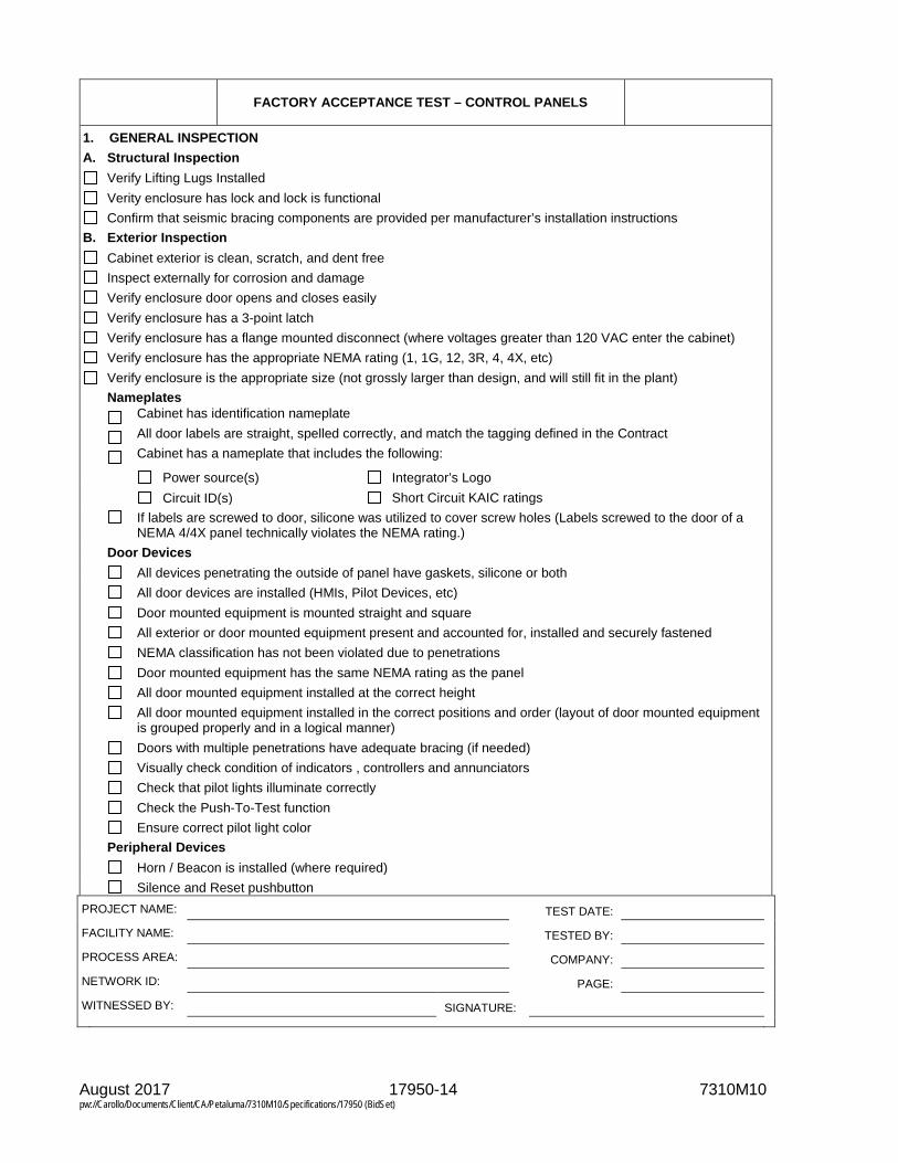
August 2017 17950-14 7310M10 pw://Carollo/Documents/Client/CA/Petaluma/7310M10/Specifications/17950 (BidSet)
FACTORY ACCEPTANCE TEST – CONTROL PANELS
1. GENERAL INSPECTION A. Structural Inspection
Verify Lifting Lugs Installed Verity enclosure has lock and lock is functional Confirm that seismic bracing components are provided per manufacturer’s installation instructions
B. Exterior Inspection Cabinet exterior is clean, scratch, and dent free Inspect externally for corrosion and damage Verify enclosure door opens and closes easily Verify enclosure has a 3-point latch Verify enclosure has a flange mounted disconnect (where voltages greater than 120 VAC enter the cabinet) Verify enclosure has the appropriate NEMA rating (1, 1G, 12, 3R, 4, 4X, etc) Verify enclosure is the appropriate size (not grossly larger than design, and will still fit in the plant)
Nameplates Cabinet has identification nameplate
All door labels are straight, spelled correctly, and match the tagging defined in the Contract
Cabinet has a nameplate that includes the following:
Power source(s) Integrator’s Logo Circuit ID(s) Short Circuit KAIC ratings If labels are screwed to door, silicone was utilized to cover screw holes (Labels screwed to the door of a
NEMA 4/4X panel technically violates the NEMA rating.) Door Devices All devices penetrating the outside of panel have gaskets, silicone or both All door devices are installed (HMIs, Pilot Devices, etc) Door mounted equipment is mounted straight and square All exterior or door mounted equipment present and accounted for, installed and securely fastened NEMA classification has not been violated due to penetrations Door mounted equipment has the same NEMA rating as the panel All door mounted equipment installed at the correct height All door mounted equipment installed in the correct positions and order (layout of door mounted equipment
is grouped properly and in a logical manner) Doors with multiple penetrations have adequate bracing (if needed) Visually check condition of indicators , controllers and annunciators Check that pilot lights illuminate correctly Check the Push-To-Test function Ensure correct pilot light color Peripheral Devices Horn / Beacon is installed (where required) Silence and Reset pushbutton PROJECT NAME: TEST DATE: FACILITY NAME: TESTED BY: PROCESS AREA: COMPANY: NETWORK ID: PAGE: WITNESSED BY: SIGNATURE:

August 2017 17950-15 7310M10 pw://Carollo/Documents/Client/CA/Petaluma/7310M10/Specifications/17950 (BidSet)
FACTORY ACCEPTANCE TEST – CONTROL PANELS
1. GENERAL INSPECTION (continued) C. Interior Inspection
Cabinet is cleaned of marks and dirt. Inspect internally for corrosion and damage. Back panel is clean of marks and dirt. Interior of panel vacuumed and shall be free of all debris. Check that the panel roof is clean and clear of foreign materials. Bottom of panel has been cut out (where bottom entry is required), with angle iron welded around the bottom
perimeter. Re-painting has been performed. If internal light door limit switch is provided, ensure the light automatically turns "on" when the doors are open. Intrusion alarms (where required).
Interior Labeling All panel mounted equipment has identification labeling, by using either a Brothers or Phenolic type tags. Verify that door mounted components are mounted square and symmetrical. Verify that nameplates are straight, legible, and spelled correctly. All terminal blocks are identified/labeled with permanent labels including tight end blocks and caps. All wiring shrink labeled and or phased correctly to the specifications. All wire labels shrunk completely rotated and aligned alike for easy identification. All fuses and circuit breakers are labeled with ID and current rating. System Integrator’s label or labels installed on door. Panel manufacturer model/serial number tag is present. All required safety/warning tags installed and straight. Correct UL (typically UL 508) or cUL tag installed and registered and all other associated tags installed and
straight (the UL tag might not be installed in the panel at the factory test. If the panel is modified due to changes during the factory test or a punch list generated from the factory test, the UL labeling would need to be re-applied. Some UL shops do not apply the UL label until the panel is released to be shipped.).
Wireways Plastic wire way covers installed properly. Plastic wireways have no sharp edges. No wire Ties inside the wireways. No sharp edges on wire ties. Separation: White duct is used for DC voltages, Gray duct is used for AC voltages. Ensure wiring duct is not over-full, includes provision for 20% more wiring and the cover may easily be
installed. Panduit recommends 50% duct fill, but 40% is a better practice. PROJECT NAME: TEST DATE: FACILITY NAME: TESTED BY: PROCESS AREA: COMPANY: NETWORK ID: PAGE: WITNESSED BY: SIGNATURE:

August 2017 17950-16 7310M10 pw://Carollo/Documents/Client/CA/Petaluma/7310M10/Specifications/17950 (BidSet)
FACTORY ACCEPTANCE TEST – CONTROL PANELS
1. GENERAL INSPECTION (continued) C. Interior Inspection (continued) Wiring Visually check terminals and condition of internal wirings Verify that the control panel has been assembled and wired as designed Verify that all components are operational and perform the functions intended Verify that all components are sized appropriately for the application Verify that equipment control circuits function as intended Back of door wiring is labeled and neatly formed Back panel to door wiring has sufficient bending radius with spiral wrap Wire connection has been verified wired to correct points within the panel Individual wires have been given a pull test to verify a good terminal connection Wire and cable minimum bending radius have not been violated All equipment installed straight and square to back panel Wire colors are correct: Black and White > AC hot and neutral, respectively Red > AC control signals Blue > DC power and control (Blue w/White stripe for DC ground) Yellow > Foreign voltages (those still present when panel power is disconnected) Green > AC equipment ground Black > TSP (+) White> TSP(-) Analog wiring shields are continuous (connected by a dedicated terminal block for such shields) Analog shield wires are grounded within the panel, where not otherwise grounded at the transmitter itself Discrete inputs are separately fused or protected by a circuit breaker on a “per loop” basis Intrinsic Safety Wiring Ensure wiring associated with intrinsic safety circuits or intrinsic safety barriers is kept away from all
other wiring by UL minimum distances or by a physical (grounded metal) barrier preventing non-intrinsically safe wiring from coming in contact with intrinsically safe circuits or wiring
Verify all spare terminals are installed according to the percentage listed in the specifications Grounding Equipped with “Blackburn” or other grounding type lug Lug is securely fastened to the panel structure Verify Grounding bar is installed Verify Isolated ground bar is installed PROJECT NAME: TEST DATE: FACILITY NAME: TESTED BY: PROCESS AREA: COMPANY: NETWORK ID: PAGE: WITNESSED BY: SIGNATURE:

August 2017 17950-17 7310M10 pw://Carollo/Documents/Client/CA/Petaluma/7310M10/Specifications/17950 (BidSet)
FACTORY ACCEPTANCE TEST – CONTROL PANELS
2. POWER TEST A. AC Power
AC Power is routed correctly within the panel, and is isolated from DC and network wiring . All fuses are installed and sized properly. All breakers are installed and sized properly . 24 VDC Power Supplies are functional. 24 VDC Power fail contacts are functional. 24 VDC power supplies are redundant, and have diode modules enabling the hot swap-over between supplies.
24 VDC supplies are equipped with dry contact failure alarms, wired as PLC inputs to signal failure of any DC power supply. Such alarm inputs to the PLC have been tested as being functional.
Dedicated receptacle is wired to receive a dedicated AC supply . Verify continuity for all DC commons, ground and AC neutrals. Verify that the CP temporary input power is connected correctly and is the correct voltage. Close the CP main circuit breaker(s). Verify that voltages at subsequent circuit breakers are correct. Close circuit breakers. Verify that power feeding interruptible and uninterruptible power supplies is correct. Turn on power supplies if they are not already on. Verify that voltages at distribution terminals are correct. Energize any remaining hardware such as the PLC.
B. Uninterruptible Power Supply (UPS) Mounted appropriately within the cabinet, on a dedicated shelf, or rear of a swing-out sub panel. Is equipped with maintenance bypass switch (or at least plug/receptacle means for bypassing the unit). Test all UPS alarms (on inverter, failure, battery failure etc) Turn off the AC power supply and verify that the UPS will be switched on to supply the designated vital loads in
the control panel. 3. CONTROLS & AUXILIARY DEVICES TEST
Verify all interposing and auxiliary relays are functioning.
Verify panel lights are functioning. Ventilation and Heating
If ventilation fans are fitted , check the fans operate correctly any associated air filters are clean and not blocked. Verify components are installed in the correct orientation for proper air flow.
4. HARDWIRED INTERLOCK AND SAFETY TEST Verify that hardwired interlocks through the control panel as shown on schematic drawings are functioning. For
example, outlet high pressure switch interlock to a pump. Verify that all hardwired safety devices through the control panel is functioning. For example, the pull cord
emergency stops of conveyors. PROJECT NAME: TEST DATE: FACILITY NAME: TESTED BY: PROCESS AREA: COMPANY: NETWORK ID: PAGE: WITNESSED BY: SIGNATURE:

August 2017 17950-18 7310M10 pw://Carollo/Documents/Client/CA/Petaluma/7310M10/Specifications/17950 (BidSet)
FACTORY ACCEPTANCE TEST – CONTROL PANELS
5. PLC TEST A. Components
PLC interior High Temperature alarm is installed, wired to the PLC, and is shown to be functional. Relays have transient suppression across their coils. This is particularly important for DC coil relays, where
diodes in reverse polarity are often used. TVSS is installed across the main incoming 120 VAC.
PLC and PLC Rack Verify all cards are securely seated. Ensure clearance around PLC rack has been met, such that convective heat transfer is not impeded by
devices erroneously mounted in the “no encroachment” area. Confirm with manufacturer clearance recommendations.
B. PLC I/O Test Furnish I/O test forms and test all the listed input and output points as follows:
Discrete Inputs: Simulate a field contact closure by “shorting” across the appropriate terminal blocks. Observe the transition between a logical “0” and “1” in the PLC software.
Discrete Outputs: Force the output bit to toggle between logical “0” and logical “1” using the PLC software. Measure contact resistance at the wired terminal blocks using a digital meter selected for the “ohms” setting.
Analog Inputs: Connect a signal generator to the appropriate terminal blocks. Tailor the connection depending on whether a 2-wire or 4-wire simulation is required. Modulate the 4-20mA signal. Observe the associated PLC internal memory register to transition between 0-65535 or if scaled in engineering units, between 0 and the maximum scaled engineering unit. The latter method is preferred.
Analog Outputs: Force the output register to a value between 0-65535 or 0-100%, if the scaling block can be manipulated. Observe the measured 4-20mA value increment and decrement using a digital ammeter.
C. Redundant Controllers (where required) Test Remove Communication cable from PLC-1 to verify switching to PLC-1A Remove Communication cable from PLC-1A to verify switching back to PLC-1 Remove Power from PLC-1 to verify switching to PLC-1A Remove Power from PLC-1A to verify switching to PLC-1 Remove Communication cable from PLC-1 to I/O rack and verify switching to PLC-1A Remove Communication cable from PLC -1A to I/O rack and verify switching to PLC-1
D. PLC Control Logic Verification The PLC control strategy is verified by following the Control Logic Verification Form based on the specifications.
Each control strategy will be verified by simulating the process and checking the state or value of PLC outputs. The results of equipment status and alarms and process instrument values and trends shall also be verified on the Plant SCADA graphic screens stored in a temporary SCADA computer. Since all PLC input and output wiring has been verified and some field devices are not available during Factory Acceptance Testing, certain inputs will be simulated either by means of additional hardware and/or software as described below.
DI states are either simulated by hardwired switches or forced inputs using a programming terminal. For example, when starters and drives are not provided as part of the contract, jumpers may be installed
from the output call relays to the running confirmation inputs to simulate the running state of the motors. AI values are either simulated by an external source or within software using a programming terminal. For example, when a level transducer is not provided as part of the contract the level transducer loop
current may be simulated with a loop powered potentiometer and adjusted manually for the level input. PROJECT NAME: TEST DATE: FACILITY NAME: TESTED BY: PROCESS AREA: COMPANY: NETWORK ID: PAGE: WITNESSED BY: SIGNATURE:

August 2017 17950-19 7310M10 pw://Carollo/Documents/Client/CA/Petaluma/7310M10/Specifications/17950 (BidSet)
FACTORY ACCEPTANCE TEST – CONTROL PANELS
5. PLC TEST (continued) D. PLC Control Logic Verification (continued) Typical Fault Logic If the fault input is high and the disable (if applicable) for the fault is not high and the common disable (if
applicable) is not high begin timing. If any of these conditions changes, stop timing and reset the timer. If the timer reaches its preset, activate the alarm output. If the fault alarm is a shutdown alarm stop the associated motor and latch the alarm so that it remains present even if the condition clears.
The fault condition must return to normal and the alarm must be reset for a latched alarm to clear. Typical Fail to Start Logic If the motor is called to run (call output high) and no running feedback is received (running input is low) and
the fail to start and common alarm disables (if applicable) are not high start timing. If any of these conditions changes, stop timing and reset the timer. If the timer reaches its preset, activate the alarm output, stop calling the motor and latch the alarm.
6. HMI OR OIT TEST HMI / OIT Functionality Communication with PLC Screen Layouts Screen Navigation Set Point Entry Animation Color Correctness (Green=Run, Red=Off, Amber=Alarm, or the agreed upon convention) Alarms Acknowledge and Reset Security / Access Levels / Passwords 7. NETWORK COMMUNICATION TEST A. Network Components Fiber optic cabling terminates in a patch panel Media converters are installed and functional Terminating resistors have been installed for trunk/tap topologies or where required Wire and cable bending limitations have not been violated B. Networking Functions Verify data transfer via the network to different PLCs as shown on the Network Block Diagrams Verify network traffic rate and error margin is acceptable PROJECT NAME: TEST DATE: FACILITY NAME: TESTED BY: PROCESS AREA: COMPANY: NETWORK ID: PAGE: WITNESSED BY: SIGNATURE:
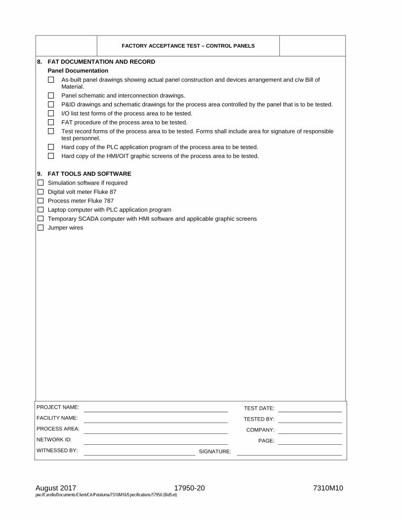
August 2017 17950-20 7310M10 pw://Carollo/Documents/Client/CA/Petaluma/7310M10/Specifications/17950 (BidSet)
FACTORY ACCEPTANCE TEST – CONTROL PANELS
8. FAT DOCUMENTATION AND RECORD Panel Documentation As-built panel drawings showing actual panel construction and devices arrangement and c/w Bill of
Material. Panel schematic and interconnection drawings. P&ID drawings and schematic drawings for the process area controlled by the panel that is to be tested. I/O list test forms of the process area to be tested. FAT procedure of the process area to be tested. Test record forms of the process area to be tested. Forms shall include area for signature of responsible
test personnel. Hard copy of the PLC application program of the process area to be tested. Hard copy of the HMI/OIT graphic screens of the process area to be tested. 9. FAT TOOLS AND SOFTWARE
Simulation software if required Digital volt meter Fluke 87 Process meter Fluke 787 Laptop computer with PLC application program Temporary SCADA computer with HMI software and applicable graphic screens Jumper wires
PROJECT NAME: TEST DATE: FACILITY NAME: TESTED BY: PROCESS AREA: COMPANY: NETWORK ID: PAGE: WITNESSED BY: SIGNATURE:

August 2017 17950-21 7310M10 pw://Carollo/Documents/Client/CA/Petaluma/7310M10/Specifications/17950 (BidSet)
INSTALLATION AND CERTIFICATION CHECKLIST DOCUMENTATION
INSTRUMENT LOOP NO.
SERVICE DESCRIPTION
A COPY OF LATEST ISSUE OF THE FOLLOWING DOCUMENTS ARE INCLUDED IN THIS INSTRUMENT INSTALLATION CERTIFICATION FILE:
INSTRUMENT SPECIFICATION SHEETS (FOR ALL INSTRUMENTS IN THE LOOP)
INSTRUMENT INSTALLATION DETAILS (FOR ALL INSTRUMENTS IN THE LOOP)
INSTRUMENT LOOP WIRING DIAGRAMS
INSTRUMENT INSTALLATION CERTIFICATION CHECKLIST
SIZING CALCULATIONS
INSTRUMENT INSTALLATION SCHEDULE (APPLICABLE PART)
NAMEPLATE SCHEDULE (APPLICABLE PART)
VENDOR LITERATURE CALIBRATION INFORMATION
INSTRUMENT LOOP IS PART OF EQUIPMENT START-UP/SHUTDOWN INTERLOCKS? No Yes
REMARKS:
CHECKED BY (COMPANY) ACCEPTED BY (COMPANY)
SIGNATURE SIGNATURE
DATE DATE

August 2017 17950-22 7310M10 pw://Carollo/Documents/Client/CA/Petaluma/7310M10/Specifications/17950 (BidSet)
SWITCHES INSTALLATION AND CALIBRATION CHECKLIST
INSTRUMENT LOOP NO.
SERVICE DESCRIPTION
CHECK BELOW, WHEN COMPLETED:
BENCH CALIBRATED PER SPECIFICATION SHEET NO.
VERIFIED PER P&ID NO.
CORRESPONDS TO SPECIFICATION SHEET NO.
WIRING CORRECT PER INSTRUMENT LOOP DRAWING NO.
INSTALLATION CORRECT PER DETAIL NO.
ACCESSORIES ARE PRESENT AND PROPERLY INSTALLED
INSTRUMENT IS ACCESSIBLE FOR MAINTENANCE OR REMOVAL
ENGRAVED LAMINATED NAMEPLATE (NO SPELLING ERRORS) PERMANENTLY INSTALLED
INSTRUMENT LOOP IS PART OF EQUIPMENT START-UP/SHUTDOWN INTERLOCKS? No Yes
FIELD CALIBRATION CHECK
CONTACT NO. FUNCTION
FOR SIGNAL
CONTACT IS TO AT SPECIFIED VALUE FOR ACTUAL TRIP POINT WAS
1 ALARM INCR OPEN SET PT = SET PT =
S/D PERM DECR CLOSE RESET = RESET =
2 ALARM INCR OPEN SET PT = SET PT =
S/D PERM DECR CLOSE RESET = RESET =
3 ALARM INCR OPEN SET PT = SET PT =
S/D PERM DECR CLOSE RESET = RESET =
4 ALARM INCR OPEN SET PT = SET PT =
S/D PERM DECR CLOSE RESET = RESET =
NOTE: PERM IS ABBREVIATION FOR PERMISSIVE

August 2017 17950-23 7310M10 pw://Carollo/Documents/Client/CA/Petaluma/7310M10/Specifications/17950 (BidSet)
SWITCHES INSTALLATION AND CALIBRATION CHECKLIST
REMARKS:
CHECKED BY (COMPANY) ACCEPTED BY (COMPANY)
SIGNATURE SIGNATURE
DATE DATE

August 2017 17950-24 7310M10 pw://Carollo/Documents/Client/CA/Petaluma/7310M10/Specifications/17950 (BidSet)
TRANSMITTER/CONTROLLER/INDICATOR INSTALLATION AND CALIBRATION CHECKLIST
INSTRUMENT LOOP IS PART OF EQUIPMENT START-UP/SHUTDOWN INTERLOCKS? No Yes
INSTRUMENT TYPE INDICATOR
TRANSMITTER CONTROLLER
OTHER DESCRIPTION
INSTRUMENT TAG NO. SERIAL NO.
SERVICE DESCRIPTION
BENCH CALIBRATION CHECK
INPUT RANGE = OUTPUT RANGE =
HEAD CORRECTION = LINEAR
CALIBRATED SPAN = SQUARE ROOT
% CALIB SPAN DESIRED VALUE ACTUAL VALUE EXPECTED VALUE ACTUAL VALUE
0
50
100
CHECK BELOW, WHEN COMPLETED:
BENCH CALIBRATED PER SPECIFICATION SHEET NO.
VERIFIED PER P&ID NO.
CORRESPONDS TO SPECIFICATION SHEET NO.
WIRING CORRECT PER INSTRUMENT LOOP DRAWING NO.
INSTALLATION CORRECT PER DETAIL NO.
ACCESSORIES ARE PRESENT AND PROPERLY INSTALLED
INSTRUMENT IS ACCESSIBLE FOR MAINTENANCE OR REMOVAL
ENGRAVED LAMINATED NAMEPLATE (NO SPELLING ERRORS) PERMANENTLY INSTALLED
FIELD CALIBRATION CHECK
INPUT RANGE =
OUTPUT RANGE =
% CALIB SPAN DESIRED VALUE ACTUAL VALUE EXPECTED VALUE ACTUAL VALUE
0
50
100

August 2017 17950-25 7310M10 pw://Carollo/Documents/Client/CA/Petaluma/7310M10/Specifications/17950 (BidSet)
TRANSMITTER/CONTROLLER/INDICATOR INSTALLATION AND CALIBRATION CHECKLIST
DIRECT REVERSE
ACTION VERIFIED AT 50% SPAN
ACTION VERIFIED AT SPAN
CONTROLLER SETTINGS
SETTING GAIN PB RESET
(INTEGRAL) DERIV. (RATE)
HIGH LIMIT
LOW LIMIT
ELEV. ZERO
ZERO SUPP
PRE-TUNE
POST-TUNE
PRE-TUNE SETTINGS
GAIN PB RESET (REPEAT/MIN) RESET (MIN/REPEAT) DERIVATION (MINUTES)
FLOW 1.0 100 10 0.1 N/A
LEVEL 1.0 100 MIN. MAX. N/A
PRESSURE 2.0 50 2.0 0.5 N/A
TEMP. 4.0 25 0.1 10 OFF
REMARKS
CHECKED BY (COMPANY) ACCEPTED BY (COMPANY)
SIGNATURE SIGNATURE
DATE DATE

August 2017 17950-26 7310M10 pw://Carollo/Documents/Client/CA/Petaluma/7310M10/Specifications/17950 (BidSet)
ANALYZERS INSTALLATION AND CALIBRATION CHECKLIST
INSTRUMENT LOOP IS PART OF EQUIPMENT START-UP/SHUTDOWN INTERLOCKS? No Yes
TYPE OF INSTRUMENT
INSTRUMENT TAG NO. SERIAL NO.
SERVICE DESCRIPTION
CHECK BELOW, IF TRUE
BENCH CALIBRATED PER SPECIFICATION SHEET NO.
VERIFIED PER P&ID NO.
CORRESPONDS TO SPECIFICATION SHEET NO.
WIRING CORRECT PER INSTRUMENT LOOP DRAWING NO.
INSTALLATION CORRECT PER DETAIL NO.
ACCESSORIES ARE PRESENT AND PROPERLY INSTALLED
INSTRUMENT IS ACCESSIBLE FOR MAINTENANCE OR REMOVAL
ENGRAVED LAMINATED NAMEPLATE (NO SPELLING ERRORS) PERMANENTLY INSTALLED
REMARKS
CHECKED BY (COMPANY) ACCEPTED BY (COMPANY)
SIGNATURE SIGNATURE
DATE DATE

August 2017 17950-27 7310M10 pw://Carollo/Documents/Client/CA/Petaluma/7310M10/Specifications/17950 (BidSet)
CONTROL VALVES INSTALLATION AND CALIBRATION CHECKLIST
INSTRUMENT LOOP IS PART OF EQUIPMENT START-UP/SHUTDOWN INTERLOCKS? No Yes
VALVE TAG NO. SERIAL NO.
TRANSDUCER TAG NO. SERIAL NO.
SOLENOID TAG NO. SERIAL NO.
VOLUME BOOSTER TAG NO.
SERIAL NO.
POSITIONER SERIAL NO.
SERVICE DESCRIPTION
TRANSDUCER CHECK
INPUT RANGE = OUTPUT RANGE =
CALIBRATED SPAN = CALIBRATED SPAN =
BENCH
SPAN DESIRED ACTUAL SPAN EXPECTED ACTUAL
0% 0%
50% 50%
100% 100%
FIELD
SPAN DESIRED ACTUAL SPAN EXPECTED ACTUAL
0% 0%
50% 50%
100% 100%
CHECK BELOW, IF TRUE:
BENCH CALIBRATED PER ABOVE
VERIFIED PER P&ID NO.
CORRESPONDS TO SPECIFICATION SHEET NO.
VALVE SPECIFICATION NO.
TRANSDUCER SPECIFICATION NO.
SOLENOID SPECIFICATION NO.
WIRING CORRECT PER INSTRUMENT LOOP DRAWING NO.
INSTALLATION CORRECT PER INSTRUMENT INSTALLATION DETAILS
VALVE DETAIL NO.
TRANSDUCER DETAIL NO.
SOLENOID DETAIL NO.
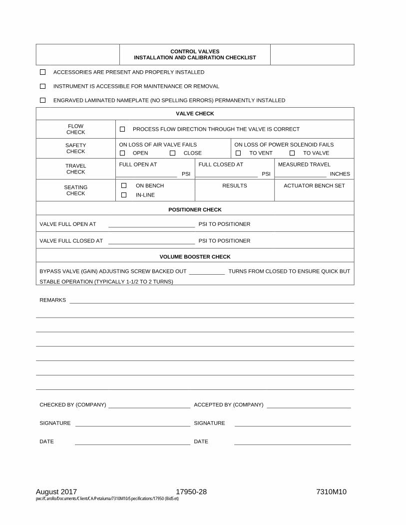
August 2017 17950-28 7310M10 pw://Carollo/Documents/Client/CA/Petaluma/7310M10/Specifications/17950 (BidSet)
CONTROL VALVES INSTALLATION AND CALIBRATION CHECKLIST
ACCESSORIES ARE PRESENT AND PROPERLY INSTALLED
INSTRUMENT IS ACCESSIBLE FOR MAINTENANCE OR REMOVAL
ENGRAVED LAMINATED NAMEPLATE (NO SPELLING ERRORS) PERMANENTLY INSTALLED
VALVE CHECK
FLOW CHECK PROCESS FLOW DIRECTION THROUGH THE VALVE IS CORRECT
SAFETY CHECK
ON LOSS OF AIR VALVE FAILS ON LOSS OF POWER SOLENOID FAILS OPEN CLOSE TO VENT TO VALVE
TRAVEL CHECK
FULL OPEN AT FULL CLOSED AT MEASURED TRAVEL
PSI PSI INCHES
SEATING CHECK
ON BENCH RESULTS ACTUATOR BENCH SET
IN-LINE
POSITIONER CHECK
VALVE FULL OPEN AT PSI TO POSITIONER
VALVE FULL CLOSED AT PSI TO POSITIONER
VOLUME BOOSTER CHECK
BYPASS VALVE (GAIN) ADJUSTING SCREW BACKED OUT TURNS FROM CLOSED TO ENSURE QUICK BUT
STABLE OPERATION (TYPICALLY 1-1/2 TO 2 TURNS)
REMARKS
CHECKED BY (COMPANY) ACCEPTED BY (COMPANY)
SIGNATURE SIGNATURE
DATE DATE

August 2017 17950-29 7310M10 pw://Carollo/Documents/Client/CA/Petaluma/7310M10/Specifications/17950 (BidSet)
DEVICENET INSTALLATION TESTING
DeviceNet Network Network Installation Characteristics Architecture Baud Rate Trunk Media Drop Media
Single Master 125 kBaud Thick Round Thick Round, Unshielded or
Multi Master 250 kBaud Thin Round Thin Round, Shielded Redundant Power Supplies 500 kBaud Thick Round, Shielded Per Network
Installed Node List 0 1 2 3 4 5 6 7 8 9 10 11 12 13 14 15 16 17 18 19 20 21 22 23 24 25 26 27 28 29 30 31 32 33 34 35 36 37 38 39 40 41 42 43 44 45 46 47 48 49 50 51 52 53 54 55 56 57 58 59 60 61 62 63
All nodes present and in accordance with network drawings/specifications ODVA approved devices
Nodes/devices accessible for inspection and maintenance Nodes/devices properly addressed Comments: Media Inspection Trunk Cable Drop Cable Installation
ODVA approved ODVA approved No evidence of physical damage Labeling complete Labeling complete Installed in protective raceway Cable/conductor
terminations Cable/conductor terminations Bending radius not exceeded
Terminating resistors at ends
Maximum drop length < 20' Cable supports in place
V- and shield are grounded Clearance from high
temperature/voltage sources No installation subject to vibration
Comments:

August 2017 17950-30 7310M10 pw://Carollo/Documents/Client/CA/Petaluma/7310M10/Specifications/17950 (BidSet)
Network Power Supplies Power Supply Equipment Supply Source (120 VAC) Network Power Tap (24 VDC)
ODVA compliant Overcurrent protection Overcurrent protection Quantity and ratings Conductor size Conductor size
Comments:
CHECKED BY (COMPANY) ACCEPTED BY (COMPANY)
SIGNATURE SIGNATURE
DATE DATE

August 2017 17950-31 7310M10 pw://Carollo/Documents/Client/CA/Petaluma/7310M10/Specifications/17950 (BidSet)
PROFIBUS INSTALLATION QUALIFICATION AND TESTING
General Network Description The Profibus network serves the RO pretreatment, blended water, and concentrate processes and consists of both DP and PA slave devices. The master is located in programmable logic controller, PLC-900. Profibus DP repeaters are deployed in the network to essentially support a radial network topology from each process control panel.
Network Design Characteristics
ARCHITECTURE BAUD RATE (kbits/sec) MASTER SINGLE REDUNDANT 9.6 187.5 3,000 TOTAL NODE COUNT ≤ 126 19.2 50 6,000 REPEATER COUNT 93.75 1,500 12,000 CASCADED REPEATER COUNT <9 NODE COUNT PER DP SEGMENT
<32
DP/PA SEGMENT COUPLERS REDUNDANCY (DP/PA COUPLERS ACTIVE TERMINATORS PROFIBUS DIAGNOSTICS PA ONLY DP & PA SURGE PROTECTION FOR SLAVES LOCATED OUTSIDE SURGE PROTECTION FOR MEDIA ENTERING THE CONTROLLER CABINET INTRINSIC SAFETY WIRING: REQUIRED FOR ANY PA NETWORK INSTALLED NODE LIST 0 1 2 3 4 5 6 7 8 9 10 11 12 13 14 15 16 17 18 19 20 21 22 23 24 25 26 27 28 29 30 31 32 33 34 35 36 37 38 39 40 41 42 43 44 45 46 47 48 49 50 51 52 53 54 55 56 57 58 59 60 61 62 63 64 65 66 67 68 69 70 71 72 73 74 75 76 77 78 79 80 81 82 83 84 85 86 87 88 89 90 91 92 93 94 95 96 97 98 99 100 101 102 103 104 105 106 107 108 109 110 111 112 113 114 115 116 117 118 119 120 121 122 123 124 125 R 126 R 127 ALL NODES PRESENT IN ACCORDANCE WITH NETWORK DESIGN DOCUMENTS. LEGEND
M MASTER NODE PRESENT AT THIS ADDRESS D PROFIBUS DP NODE PRESENT AT THIS ADDRESS P PROFIBUS PA NODE PRESENT AT THIS ADDRESS R RESERVED ADDRESS NO DEVICE PRESENT AT THIS ADDRESS COMMENTS (Comments referenced by number. Refer to the Comments, Observations, and Recommendations Summary.)
PROJECT NAME: TEST DATE: FACILITY NAME: TESTED BY: PROCESS AREA: COMPANY: NETWORK ID: PAGE: WITNESSED BY: SIGNATURE:

August 2017 17950-32 7310M10 pw://Carollo/Documents/Client/CA/Petaluma/7310M10/Specifications/17950 (BidSet)
PROFIBUS INSTALLATION QUALIFICATION AND TESTING
Media Inspection
CABLING
DP NETWORK PA NETWORK SEGMENTS
PI COMPLIANT LABELING COMPLETE GROUNDING CABLE AND CONDUCTOR TERMINATIONS NO STUB LINES (DP ONLY) TERMINATING RESISTORS (IN PLACE) DEDICATED DIAGNOSTICS BUS INSTALLATION NO EVIDENCE OF PHYSICAL DAMAGE INSTALLATION IN PROTECTIVE RACEWAY CLEARANCES FROM HIGH TEMPERATURE SOURCES CLEARANCES FROM HIGH VOLTAGE SOURCES BEND RADIUS NO INSTALLATION SUBJECT TO VIBRATION, SHOCK, HIGH FLEX,
CHEMICALS, OR MOISTURE
TERMINATING RESISTORS TURNED ON AT CORRECT LOCATION COMMENTS (Comments referenced by number. Refer to the Comments, Observations, and Recommendations Summary.)
Device Inspection
DEVICE QUANTITY/TYPE INSTALLATION TOTAL SLAVE COUNT NO EVIDENCE OF PHYSICAL DAMAGE MOST UPDATED DEVICE DRIVER INSTALLED? ACCESSIBLE FOR INSPECTION AND MAINTENANCE INSTALLED DEVICES COMPLY WITH DRAWINGS
AND SPECIFICATIONS FDT COMPLIANT DEVICES
PI COMPLIANCE DEVICES DIAGNOSTICS MODULE INSTALLED COMMENTS (Comments referenced by number. Refer to the Comments, Observations, and Recommendations Summary.)
Power Supplies
ACTIVE TERMINATIONS COUPLERS REPEATERS SOURCE LOCATION SOURCE LOCATION SOURCE LOCATION OVERCURRENT PROTECTION OVERCURRENT PROTECTION OVERCURRENT PROTECTION CONDUCTOR SIZE CONDUCTOR SIZE CONDUCTOR SIZE GROUNDING GROUNDING GROUNDING COMMENTS (Comments referenced by number. Refer to the Comments, Observations, and Recommendations Summary.)
PROJECT NAME: TEST DATE: FACILITY NAME: TESTED BY: PROCESS AREA: COMPANY: NETWORK ID: PAGE: WITNESSED BY: SIGNATURE:

August 2017 17950-33 7310M10 pw://Carollo/Documents/Client/CA/Petaluma/7310M10/Specifications/17950 (BidSet)
PROFIBUS INSTALLATION QUALIFICATION AND TESTING
DP Network Media Testing DESCRIPTION SEGMENT ID
TRUNK LENGTH (feet) ALLOWABLE TRUNK LENGTH AT SPECIFIED DATA RATE: MEASURED TRUNK LENGTH: SPARE TRUNK LENGTH RESISTANCE MEASUREMENTS (ohms) NETWORK CABLE: NO TERMINATIONS ONE TERMINATION TWO TERMINATIONS POWER SUPPLY VOLTAGE (volts DC) ACTIVE TERMINATOR REPEATER CP1100-RPT1 REPEATER CP1000-RPT1 REPEATER CP1000-RPT2 REPEATER CP2700-RPT1 CABLE TEXTS PASS FAIL PASS FAIL PASS FAIL PASS FAIL PASS FAIL PASS FAIL TESTED FOR SHORT CIRCUIT BETWEEN SIGNAL LINES TESTED FOR SHORT CIRCUIT BETWEEN SIGNAL LINES AND SHIELD TESTED FOR SHIELD CONTINUITY TESTED FOR OPEN SIGNAL LINES TESTED FOR CROSSED SIGNAL LINES TESTED FOR CORRECT TERMINATOR POSITION CORRECT CABLE TYPE AND LENGTH TESTED FOR SECURE AND TIGHT CONNECTORS COMMENTS (Comments referenced by number. Refer to the Comments, Observations, and Recommendations Summary.)
PROJECT NAME: TEST DATE: FACILITY NAME: TESTED BY: PROCESS AREA: COMPANY: NETWORK ID: PAGE: WITNESSED BY: SIGNATURE: