Embed Size (px)
Citation preview

Copy No.
CITY OF FLINT, MICHIGAN
WATER POLLUTION CONTROL
AERATION SYSTEM IMPROVEMENTS
Contract Number 200-156238-19001
SRF No. 5696-01
Bidding Documents
Specifications
Prepared by
Lansing, Michigan
May 2020

p:\ier\156238\200-156238-19001\docs\specs\000z - cover.doc

CONTENTS
Section Number Title Pages
City of Flint WPC
Aeration System Improvements
SRF No. 5696-01
200-156238-19001 TC-1 052920
00100 ADVERTISEMENT FOR BIDS 00100 - 1 to 2
00110 CONTRACTOR’S QUALIFICATION STATEMENT 00110 - 1 to 8
00200 INSTRUCTION TO BIDDERS 00200 - 1 to 9
00400 BID FORM 00400 - 1 to 7
00430 BID BOND 00430 - 1 to 2
00450 REQUIRED CONTRACT LANGUAGE – SRF 00450 - 1 to 30
00458 AMERICAN IRON AND STEEL CONTRACT LANGUAGE 00458 - 1 to 1
00500 AGREEMENT 00500 - 1 to 8
00510 NOTICE OF AWARD 00510 - 1 to 2
00550 NOTICE TO PROCEED 00550 - 1 to 1
00613 PERFORMANCE BOND 00613 - 1 to 2
00614 PAYMENT BOND 00614 - 1 to 2
00615 ACT NO. 524, MICHIGAN P.A. 1980 00615 - 1 to 4
00620 APPLICATION FOR PAYMENT CERTIFICATE 00620 - 1 to 3
00623 CERTIFICATES OF INSURANCE 00623 - 1 to 1
00625 CERTIFICATE OF COMPONENT ACCEPTANCE 00625 - 1 to 1
00626 CERTIFICATE OF SUBSTANTIAL COMPLETION 00626 - 1 to 2
00627 CERTIFICATE OF FINAL COMPLETION 00627 - 1 to 2
00700 GENERAL CONDITIONS, EJCDC 1996 EDITION 00700 - 1 to 39
00800 SUPPLEMENTARY CONDITIONS 00800 - 1 to 13
DIVISION 1 - GENERAL REQUIREMENTS
01110 Summary of Work 01110 - 1 to 3
01210 Allowances 01210 - 1 to 3
01230 Alternates 01230 - 1 to 3
01290 Applications for Payment 01290 - 1 to 3
01310 Project Coordination 01310 - 1 to 4
01330 Submittals 01330 - 1 to 7
01420 Definitions and Standards 01420 - 1 to 5
01450 Quality Control Services 01450 - 1 to 3
01500 Temporary Facilities 01500 - 1 to 16
01600 General Equipment Stipulations 01600 - 1 to 6
01730 Cutting and Patching 01730 - 1 to 3
01770 Contract Closeout 01770 - 1 to 5
DIVISION 2 - SITE WORK
02225 Selective Demolition 02225 - 1 to 7
02805 Restoration Work 02805 - 1 to 8
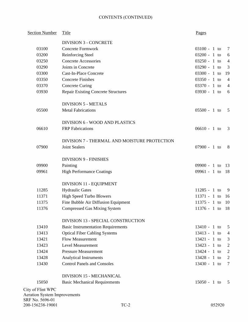
CONTENTS (CONTINUED)
Section Number Title Pages
City of Flint WPC
Aeration System Improvements
SRF No. 5696-01
200-156238-19001 TC-2 052920
DIVISION 3 - CONCRETE
03100 Concrete Formwork 03100 - 1 to 7
03200 Reinforcing Steel 03200 - 1 to 6
03250 Concrete Accessories 03250 - 1 to 4
03290 Joints in Concrete 03290 - 1 to 3
03300 Cast-In-Place Concrete 03300 - 1 to 19
03350 Concrete Finishes 03350 - 1 to 4
03370 Concrete Curing 03370 - 1 to 4
03930 Repair Existing Concrete Structures 03930 - 1 to 6
DIVISION 5 - METALS
05500 Metal Fabrications 05500 - 1 to 5
DIVISION 6 - WOOD AND PLASTICS
06610 FRP Fabrications 06610 - 1 to 3
DIVISION 7 - THERMAL AND MOISTURE PROTECTION
07900 Joint Sealers 07900 - 1 to 8
DIVISION 9 - FINISHES
09900 Painting 09900 - 1 to 13
09961 High Performance Coatings 09961 - 1 to 18
DIVISION 11 - EQUIPMENT
11285 Hydraulic Gates 11285 - 1 to 9
11371 High Speed Turbo Blowers 11371 - 1 to 16
11375 Fine Bubble Air Diffusion Equipment 11375 - 1 to 10
11376 Compressed Gas Mixing System 11376 - 1 to 18
DIVISION 13 - SPECIAL CONSTRUCTION
13410 Basic Instrumentation Requirements 13410 - 1 to 5
13413 Optical Fiber Cabling Systems 13413 - 1 to 4
13421 Flow Measurement 13421 - 1 to 3
13423 Level Measurement 13423 - 1 to 2
13424 Pressure Measurement 13424 - 1 to 2
13428 Analytical Instruments 13428 - 1 to 2
13430 Control Panels and Consoles 13430 - 1 to 7
DIVISION 15 - MECHANICAL
15050 Basic Mechanical Requirements 15050 - 1 to 5

CONTENTS (CONTINUED)
Section Number Title Pages
City of Flint WPC
Aeration System Improvements
SRF No. 5696-01
200-156238-19001 TC-3 052920
15060 Supports and Anchors 15060 - 1 to 6
15080 Mechanical Insulation 15080 - 1 to 7
15100 Pressure Process Piping 15100 - 1 to 16
15105 Basic Piping Materials and Methods 15105 - 1 to 16
15110 Process Valves 15110 - 1 to 11
15115 Plumbing Valves 15115 - 1 to 7
15125 Meters, Gauges, Switches, and Controls 15125 - 1 to 2
15140 Water Distribution Piping 15140 - 1 to 10
15150 Drainage and Vent Systems 15150 - 1 to 6
15212 Compressed Air Systems 15212 - 1 to 5
DIVISION 16 - ELECTRICAL
16050 Basic Electrical Requirements 16050 - 1 to 8
16052 Coordination Study and Arc Flash Analysis 16052 - 1 to 6
16060 Grounding 16060 - 1 to 3
16070 Supporting Devices 16070 - 1 to 2
16075 Electrical Identification 16075 - 1 to 3
16090 Demolition and Earthwork 16090 - 1 to 4
16120 Wires and Cables 16120 - 1 to 5
16130 Raceways 16130 - 1 to 4
16135 Cabinets, Boxes, and Fittings 16135 - 1 to 4
16139 Vaults 16139 - 1 to 5
16140 Wiring Devices 16140 - 1 to 2
16220 Motors 16220 - 1 to 5
16270 Transformers 16270 - 1 to 2
16330 Medium-Voltage Transformers 16330 - 1 to 7
16334 Medium-Voltage Switchgear 16334 - 1 to 5
16410 Circuit and Motor Disconnects 16410 - 1 to 2
16420 Motor Controllers 16420 - 1 to 3
16421 Motor Control Centers 16420 - 1 to 4
16440 Panelboards 16440 - 1 to 2
16450 Busways 16450 - 1 to 3
16497 Fuses 16497 - 1 to 2
16529 Hazardous Material Disposal 16529 - 1 to 2

City of Flint WPC
Aeration System Improvements
SRF No. 5696-01
200-156238-19001 00100-1 052920
ADVERTISEMENT FOR BIDS
CITY OF FLINT WPC
AERATION SYSTEM IMPROVEMENTS
SRF No. 5693-01
Contract 200-156238-19001
Sealed Bids will be received by the City of Flint, Michigan at the office of the City of Flint Finance Department
– Division of Purchases and Supplies, 1101 S Saginaw St, Room 203, Flint MI 48502 up to 3:00 p.m.,
prevailing local time, on June 29, 2020, and then publicly opened and read aloud for the construction of
Contract 200-156238-19001. One fully completed digital copy and hard copy of the Bid, including all
necessary support forms shall be submitted at time of bid. The digital copy of bid shall be submitted to City of
Flint Finance Department – Division of Purchases and Supplies at [email protected].
The Work consists of improvements to the aeration system at the City of Flint Water Pollution Control Facility.
The works includes installation of three new aeration blowers. Also includes installation of a low energy mixing
system in secondary treatment influent and effluent channels, portions of the Battery B Aeration tanks and
primary tank influent channels. The works also includes installation of fine bubble diffuser equipment in one
tank of the Battery B aeration system, replacement of valves, piping and instrumentation within the Aeration
Tank Galleries, replacement and removal of a number of existing channel gates, concrete repairs to the existing
structures, and electrical and instrumentation improvements.
Bids shall be on a lump sum basis for the Work.
The Drawings and Project Manual under which the Work is to be done are on file and may be examined at the
office of the City of Flint Water Pollution Control Facility; at Construction Association of Michigan in
Bloomfield Hills, Michigan; at McGraw-Hill Construction Dodge,; at Builders Exchange of Grand Rapids,
Lansing, and Saginaw, Michigan; at Construction News Service in Detroit, Michigan; and at the office of the
ENGINEER, Tetra Tech, Inc., 401 S. Washington Square Suite 100, Lansing, Michigan 48933.
Bidding Documents may be obtained on or after May 29, 2020, through the City of Flint, Finance Department
Division of Purchases and Supplies. Plans will be available to view, purchase or download from on the City’s
Purchasing page of the City of Flint’s web site at https://www.cityofflint.com/finance/purchasing/bids-2/ under
“open bids” and the specific bid or proposal number assigned.
A Bid Security in the form of a certified check, bank check, or Bid Bond for a sum not less than five percent (5%)
of the amount of the Bid will be required with each Bid.
The right is reserved by OWNER to accept any Bid, to reject any Bid, and to waive irregularities in Bids.
A mandatory Pre-Bid Conference will be held at 9:00 a.m. on June 9, 2020, at City of Flint Water Pollution
Control Facility, 4652 Beecher Road, Flint MI 48532. Attendance at meeting at the site is not allowed; bidder
shall attend through virtual meeting. Representatives of OWNER and ENGINEER will be present to discuss the
Project. Bidders are required to attend and participate in the conference via Windows Teams meeting
attendance. Interested parties wishing to attend the Pre-Bid meeting shall request meeting attendance
information no later than 4:00 p.m on June 8, 2020 from [email protected]. The necessary login
information shall then be provided.

City of Flint WPC
Aeration System Improvements
SRF No. 5696-01
200-156238-19001 00100-2 052920
Interested bidder may schedule a tour of the Site per details provided at Pre-Bid meeting. Prospective Bidders
who fail to attend and register at the meeting will be disqualified from bidding for the Work. ENGINEER will
transmit to all prospective Bidders of record such Addenda as ENGINEER considers necessary in response to
questions arising at the conference. Oral statements may not be relied upon and will not be binding or legally
effective.
CONTRACTOR will not engage in unlawful discrimination on the basis of race, color, religion, national origin,
age, sex, height, weight, marital status, or unrelated disability. Bids from minority- and female-owned
organizations are encouraged.
This Contract is funded with a State Revolving Fund (SRF) loan. Bidders are required to complete the
Certification Regarding Debarment, Suspension and other Responsibility Matters statement included in the
Project Manual.
This Contract requires the use of prevailing wage rates. Other specific funding requirements are included in the
Project Manual.
No Bids may be withdrawn after the above date and time for receiving Bids for a period of ninety (90) days.
Joyce McClane
City of Flint Division of Purchases and Supplies

City of Flint WPC
Aeration System Improvements
SRF No. 5696-01
200-156238-19001 00110-1 052920
SECTION 00110 - CONTRACTOR’S QUALIFICATION STATEMENT
This Section shall be completed upon request of OWNER to demonstrate Bidder’s qualifications to enter into
Contract with and to perform the Work for OWNER.
1. Project Information:
OWNER: City of Flint, MI Water Pollution Control
Address:
Project: Aeration System Improvements
Contract No. 200-156238-19001
2. Bidder Information:
Name of Organization:
Address:
Telephone:
Facsimile:
3. Surety company:
Name of Surety:
Agent’s Name:
Surety Rating: A.M. Best’s Rating
Address:
Telephone:
Facsimile:
4. Type of Organization, check if:
Corporation Partnership Joint Venture Sole Proprietorship

City of Flint WPC
Aeration System Improvements
SRF No. 5696-01
200-156238-19001 00110-2 052920
If Corporation:
Date and State of Incorporation
List of Executive Officers
Name Title
If Partnership:
Date and State of Organization:
Names of Current General Partners
Type of Partnership
General Publicly Traded
Limited Other (describe):
If Joint Venture:
Date and State of Organization:
Name, Address and Form of Organization of Joint Venture Partners: (Indicate managing partner by an
asterisk *)
If Sole Proprietorship:
Date and State of Organization:
Name and Address of Owner or Owners
5. Completed Projects: In Schedule A, provide the following for projects completed within the past five
years (If joint venture, list each participant's projects separately):
A. List major engineered construction projects completed by this organization.
B. Has your organization ever failed to complete any work awarded to it?
C. Has your organization ever failed to substantially complete a project in a timely manner?

City of Flint WPC
Aeration System Improvements
SRF No. 5696-01
200-156238-19001 00110-3 052920
D. Are there any judgments, claims, arbitration proceedings or suits pending or outstanding against your
organization or its officers?
E. Has your organization filed any lawsuits or requested arbitration with regard to construction
contracts?
F. Has any Corporate officer, partner, joint venture participant or proprietor ever failed to complete a
construction contract awarded to him or her in their own name or when acting as a principal of
another organization?
G. Is your organization a member of a controlled group of corporations as defined in I.R.C. Sec. 1563?
Yes No
If yes, show names and addresses of affiliated companies.
6. Current Projects: In Schedule B, provide the following (If joint venture, list each participant's projects
separately):
A. List major engineered construction projects under current contract by this organization.
B. Are there any projects that are beyond final completion date?
C. Are there any projects that have liquidated damages presently being assessed?
D. Are there any judgments, claims, arbitration proceedings or suits pending or outstanding against your
organization or its officers?
E. Has your organization filed any lawsuits or requested arbitration on any of these projects?
7. Financial Resources:
A. Provide complete financial statement for firm.
B. Provide in Schedule C, equipment owned by firm. Include manufacturer’s name, description, size
and or capacity, and age.
C. Provide the following information with respect to an accredited banking institution familiar with
your organization.
Name of Bank:
Address:
Account Manager:
Telephone:
Facsimile:

City of Flint WPC
Aeration System Improvements
SRF No. 5696-01
200-156238-19001 00110-4 052920
D. What is your approximate total bonding capacity (circle one)?
$500,000 to $2,000,000
$2,000,000 to $5,000,000
$5,000,000 to $10,000,000
$10,000,000 or more
8. Experience Record: In Schedule D, provide:
A. Details of the construction experience of the principal individuals of your organization directly
involved in construction operations.
B. Indicate general types of work performed with your own work force.
9. Safety: Describe the permanent safety program you maintain within your organization (use attachment if
necessary).
A. Submit a copy of the Bidder's current Experience Modification Rates (EMR).
B. Submit Bidder's OSHA Form 200 recordable incidence rate for the last calendar year, per 200,000
man-hours, for:
1. Total cases.
2. Lost workday cases.
3. Non-fatal cases per number of lost workdays.
I hereby certify that the information submitted herewith, including any attachment is true to the best of my
knowledge and belief.
Subscribed and sworn to
before me on
By:
County, Michigan Title:
Signature Dated:
Printed:
Notary Public

City of Flint WPC
Aeration System Improvements
SRF No. 5696-01
200-156238-19001 00110-5 05292020
COMPLETED PROJECTS
SCHEDULE A
Name, Location, and
Description of Project Owner
Design
Engineer
Date
Completed
Contract
Price
5.B.
Yes / No
5.C.
Yes / No
5.D.
Yes / No
5.E.
Yes / No
5.F.
Yes / No
Reference/Contact
Include Address & Phone
If any of questions 5.B. through F is yes, then attach written explanation.
City of Flint WPC
Aeration System Improvements
SRF No. 5696-01
200-156238-19001 00110-6 05292020
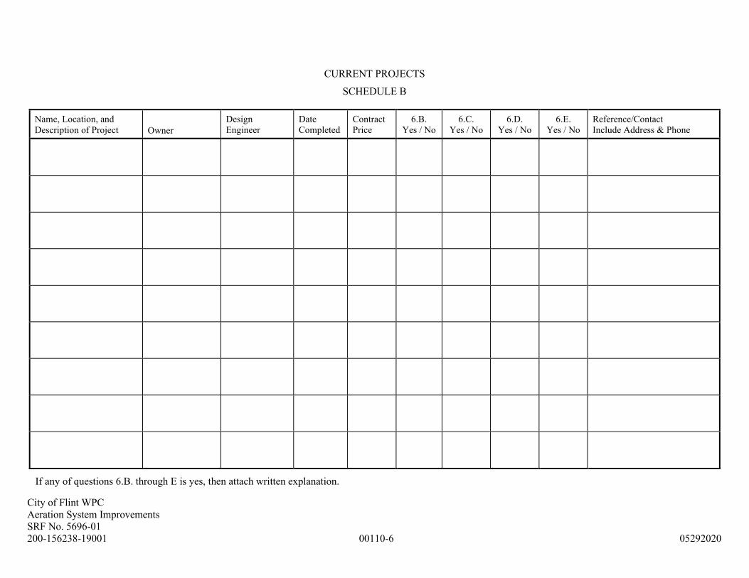
CURRENT PROJECTS
SCHEDULE B
Name, Location, and
Description of Project Owner
Design
Engineer
Date
Completed
Contract
Price
6.B.
Yes / No
6.C.
Yes / No
6.D.
Yes / No
6.E.
Yes / No
Reference/Contact
Include Address & Phone
If any of questions 6.B. through E is yes, then attach written explanation.

City of Flint WPC
Aeration System Improvements
SRF No. 5696-01
200-156238-19001 00110-7 05292020
FINANCIAL RESOURCES
SCHEDULE C
Owned Equipment Description Manufacturer’s Name Size or Capacity Age Condition Location Stored

City of Flint WPC
Aeration System Improvements
SRF No. 5696-01
200-156238-19001 00110-8 05292020
EXPERIENCE RECORD
SCHEDULE D
Person’s Name
Position
Date started with
this Firm
Year started in
Construction
Prior positions and experience
in Construction
General Types of Work Performed by Own Work Force:

City of Flint WPC
Aeration System Improvements
SRF No. 5696-01
200-156238-19001 00200-1 052920
SECTION 00200 - INSTRUCTION TO BIDDERS
ARTICLE 1 - DEFINED TERMS
1.01 Terms used in these Instructions to Bidders will have the meanings indicated in the General Conditions and
Supplementary Conditions. Additional terms used in these Instructions to Bidders have the meanings
indicated below which are applicable to both the singular and plural thereof:
A. Bidder: The individual or entity who submits a Bid directly to OWNER.
B. Issuing Office: The office from which the Bidding Documents are to be issued and where the bidding
procedures are to be administered.
C. Successful Bidder: The lowest responsible Bidder submitting a responsive Bid to whom OWNER (on
the basis of OWNER’s evaluation as hereinafter provided) makes an award.
ARTICLE 2 - COPIES OF BIDDING DOCUMENTS
2.01 Complete sets of the Bidding Documents for the purchase sum, if any, stated in the Advertisement or
Invitation to Bid may be obtained from the Issuing Office.
A. Upon written request, copies of the Bidding Drawings, in their entirety or by individual Drawing, may
be obtained in electronic format from the Issuing Office for the purchase sum of $30 per Drawing.
Upon receipt of payment, Drawings will be made available in the latest version of AutoCAD and
transmitted to Bidder on a CD or DVD. E-mail transfer of Bidding Drawings will not be permitted.
2.02 Complete sets of Bidding Documents must be used in preparing Bids; neither OWNER nor ENGINEER
assumes any responsibility for errors or misinterpretations resulting from the use of incomplete sets of
Bidding Documents.
2.03 OWNER and ENGINEER in making copies of Bidding Documents available on the above terms do so only
for the purpose of obtaining Bids for the Work and do not confer a license or grant for any other use.
ARTICLE 3 - QUALIFICATIONS OF BIDDERS
A. Each Bidder shall submit to ENGINEER the following information pertaining to its
financial resources, adequacy of plant and equipment, organization, prior experience and
other facts, as their qualification to enter into contract with and to perform the Work for
OWNER.
1. Section 00110 - Contractor’s Qualification Statement, including Schedules A, B, C,
and D.
2. Bidders must demonstrate in Schedule A, a minimum of two project experiences that are
similar to or larger than this Project. Projects must be similar in nature to this Project
description. Bidders who cannot demonstrate project experience of this type or size must
demonstrate an experience in other types of construction projects of comparable
complexity.

City of Flint WPC
Aeration System Improvements
SRF No. 5696-01
200-156238-19001 00200-2 052920
a. Subcontractors, when required to be identified in the Bid, may be required to
complete the Contractor’s Qualification Statement for Engineered Construction,
including Schedules A, B, C, and D. Subcontractor’s may be required to demonstrate
a project experience record as required in this Paragraph.
ARTICLE 4 - EXAMINATION OF BIDDING DOCUMENTS, OTHER RELATED DATA, AND SITE
4.01 It is the responsibility of each Bidder before submitting a Bid:
A. To examine and carefully study the Bidding Documents, including any Addenda and other related
data identified in the Bidding Documents (including "technical data" referred to in Paragraphs 4.02
through 4.05, inclusive);
B. To visit the Site and become familiar with and satisfy Bidder as to the general, local, and Site
conditions that may affect cost, progress, and performance of the Work;
C. To become familiar with and satisfy Bidder as to all Federal, State, and local Laws and Regulations
that may affect cost, progress, and performance of the Work;
D. To promptly notify ENGINEER of all conflicts, errors, ambiguities, or discrepancies which Bidder
has discovered in or between the Contract Documents and such other related documents;
E. To carefully study all reports of explorations and tests of subsurface conditions at or contiguous to the
Site and all drawings of physical conditions in or relating to existing surface or subsurface structures at
or contiguous to the Site (except Underground Facilities) which have been identified in the
Supplementary Conditions as provided in Paragraph 4.02 of the General Conditions, and carefully
study all reports and drawings of a Hazardous Environmental Condition, if any, at the Site which have
been identified in the Supplementary Conditions as provided in Paragraph 4.06 of the General
Conditions;
F. To obtain and carefully study (or assume responsibility for doing so) all additional or supplementary
examinations, investigations, explorations, tests, studies, and data concerning conditions (surface,
subsurface, and Underground Facilities) at or contiguous to the Site which may affect cost, progress, or
performance of the Work or which relate to any aspect of the means, methods, techniques, sequences,
and procedures of construction to be employed by Bidder, including any specific means, methods,
techniques, sequences, and procedures of construction expressly required by the Bidding Documents,
and safety precautions and programs incident thereto;
G. To agree at the time of submitting its Bid that no further examinations, investigations, explorations,
tests, studies, or data are necessary for the determination of its Bid for performance of the Work at the
price bid and within the times and in accordance with the other terms and conditions of the Bidding
Documents;
H. To correlate the information known to Bidder, information and observations obtained from visits to the
Site, reports and drawings identified in the Bidding Documents, and all additional examinations,
investigations, explorations, tests, studies, and data with the Bidding Documents;
I. To determine that the Bidding Documents are generally sufficient to indicate and convey
understanding of all terms and conditions for the performance of the Work;

City of Flint WPC
Aeration System Improvements
SRF No. 5696-01
200-156238-19001 00200-3 052920
4.02 Subsurface and Physical Conditions
A. The Supplementary Conditions identify:
1. Those reports of explorations and tests of subsurface conditions at or contiguous to the Site that
ENGINEER has used in preparing the Bidding Documents.
2. Those drawings of physical conditions in or relating to existing surface and subsurface structures
at or contiguous to the Site (except Underground Facilities) that ENGINEER has used in
preparing the Bidding Documents.
B. Provisions concerning responsibilities for the adequacy of data furnished to prospective Bidders with
respect to subsurface conditions, other physical conditions, and Underground Facilities, and possible
changes in the Bidding Documents due to differing or unanticipated conditions appear in Paragraphs
4.02, 4.03, and 4.04 of the General Conditions.
4.03 Underground Facilities
A. Information and data shown or indicated in the Bidding Documents with respect to existing
Underground Facilities at or contiguous to the Site is based upon information and data furnished to
OWNER and ENGINEER by owners of such Underground Facilities, including OWNER, or others.
4.04 Hazardous Environmental Condition(s)
A. The Supplementary Conditions identify:
1. Those reports and drawings relating to Hazardous Environmental Condition(s) identified at the
Site, if any, that ENGINEER has used in preparing the Bidding Documents are identified in
Paragraph 4.06.
B. Copies of reports and drawings referenced in Paragraph 4.04.A, that are not included with Bidding
Documents, may be examined City of Flint Water Pollution Control Facility, 4652 Beecher Road,
Flint MI 48532during regular business hours. Those reports and drawings are not part of the Contract
Documents, but the "technical data" contained therein upon which Bidder is entitled to rely as provided
in Paragraph 4.06 of the General Conditions has been identified and established in Paragraph 4.06 of
the Supplementary Conditions. Bidder is responsible for any interpretation or conclusion Bidder draws
from any “technical data” or any other data, interpretations, opinions, or information contained in such
reports or shown or indicated on such drawings.
C. Provisions concerning responsibilities for the adequacy of data furnished to prospective Bidders with
respect to a Hazardous Environmental Condition at the Site, if any, and possible changes in the
Contract Documents due to any Hazardous Environmental Condition uncovered or revealed at the Site
which was not shown or indicated on Drawings or Specifications or identified in the Contract
Documents to be within the scope of the Work appear in Paragraph 4.06 of the General Conditions.
4.05 The submission of a Bid will constitute an incontrovertible representation by Bidder that Bidder has
complied with every requirement of this Article 4, that without exception the Bid is premised upon
performing and furnishing the Work required by the Bidding Documents and applying any specific means,
methods, techniques, sequences, and procedures of construction that may be shown or indicated or expressly
required by the Bidding Documents, that Bidder has given ENGINEER written notice of all conflicts, errors,
ambiguities, and discrepancies that Bidder has discovered in the Bidding Documents and the written

City of Flint WPC
Aeration System Improvements
SRF No. 5696-01
200-156238-19001 00200-4 052920
resolutions thereof by ENGINEER are acceptable to Bidder, and that the Bidding Documents are generally
sufficient to indicate and convey understanding of all terms and conditions for performing and furnishing
the Work.
ARTICLE 5 - PRE-BID CONFERENCE
A mandatory Pre-Bid Conference will be held at 9:00 a.m. on June 9, 2020, at City of Flint Water Pollution
Control Facility, 4652 Beecher Road, Flint MI 48532. Attendance of meeting at the site is not allowed; bidder
shall attend through virtual meeting. Representatives of OWNER and ENGINEER will be present to discuss the
Project. Bidders are required to attend and participate in the conference via Windows Teams meeting
attendance. Interested parties wishing to attend the Pre-Bid meeting shall request meeting attendance
information no later than 4:00 p.m. on June 8, 2020, from ENGINEER at [email protected]. The
necessary login information shall then be provided. Interested bidder may schedule a tour of the Site per details
provide at Pre-Bid meeting. Prospective Bidders who fail to attend and register at the meeting will be
disqualified from bidding for the Work. ENGINEER will transmit to all prospective Bidders of record such
Addenda as ENGINEER considers necessary in response to questions arising at the conference. Oral statements
may not be relied upon and will not be binding or legally effective.
ARTICLE 6 - SITE AND OTHER AREAS
6.01 The Site is identified in the Bidding Documents. All additional lands and access thereto required for
temporary construction facilities, construction equipment, or storage of materials and equipment to be
incorporated in Work are to be obtained and paid for by CONTRACTOR. Easements for permanent
structures or permanent changes in existing facilities are to be obtained and paid for by OWNER unless
otherwise provided in the Bidding Documents.
ARTICLE 7 - INTERPRETATIONS AND ADDENDA
7.01 All questions about the meaning or intent of the Bidding Documents are to be submitted to ENGINEER in
writing. Interpretations or clarifications considered necessary by ENGINEER in response to such questions
will be issued by Addenda mailed or delivered to all parties recorded by ENGINEER as having received the
Bidding Documents. Questions received less than ten days prior to the date for opening of Bids may not be
answered. Only questions answered by Addenda will be binding. Oral and other interpretations or
clarifications will be without legal effect.
7.02 Addenda may be issued to clarify, correct, or change the Bidding Documents as deemed advisable by
OWNER or ENGINEER.
ARTICLE 8 - BID SECURITY
8.01 A Bid must be accompanied by Bid Security made payable to OWNER in an amount of five percent of
Bidder’s maximum Bid price and in the form of a certified check, bank check, or a Bid Bond on the form
attached in Section 00430, issued by a surety meeting the requirements of Paragraphs 5.01 and 5.02 of the
General Conditions.
8.02 The Bid Security of the Successful Bidder will be retained until such Bidder has executed the Contract
Documents, furnished the required Contract Security and met the other conditions of the Notice of Award,
whereupon the Bid Security will be returned. If the Successful Bidder fails to execute and deliver the
Contract Documents and furnish the required Contract Security within ten (10) days after the Notice of
Award, OWNER may annul the Notice of Award and the Bid Security of that Bidder will be forfeited. The
City of Flint WPC
Aeration System Improvements
SRF No. 5696-01
200-156238-19001 00200-5 052920
Bid Security of other Bidders whom OWNER believes to have a reasonable chance of receiving the award
may be retained by OWNER until the earlier of seven (7) days after the Effective Date of the Agreement or
91 days after the Bid opening, whereupon Bid Security furnished by such Bidders will be returned.
8.03 Bid Security of other Bidders whom OWNER believes do not have a reasonable chance of receiving the
award will be returned within seven (7) days after the Bid opening.
ARTICLE 9 - CONTRACT TIMES
9.01 The number of days within which, or the dates by which, the Work is to be (a) Substantially Completed,
(b) Milestones (if any), and (c) also completed and ready for final payment are set forth in the Agreement.
ARTICLE 10 - LIQUIDATED DAMAGES
10.01 Provisions for liquidated damages, if any, are set forth in the Agreement.
ARTICLE 11 - SUBSTITUTE AND "OR-EQUAL" ITEMS
11.01 The Contract, if awarded, will be on the basis of materials and equipment specified or described in the
Bidding Documents without consideration of possible substitute or "or-equal" items. Whenever it is
specified or described in the Bidding Documents that a substitute or "or-equal" item of material or
equipment may be furnished or used by CONTRACTOR if acceptable to ENGINEER, application for such
acceptance will not be considered by ENGINEER until after the Effective Date of the Agreement. The
procedure for submission of any such application by CONTRACTOR and consideration by ENGINEER is
set forth in the General Conditions and may be supplemented in the General Requirements.
ARTICLE 12 - SUBCONTRACTORS, SUPPLIERS, AND OTHERS
12.01 If the Supplementary Conditions require the identity of certain Subcontractors, Suppliers, individuals, or
entities to be submitted to OWNER in advance of a specified date prior to the Effective Date of the
Agreement, the apparent Successful Bidder, and any other Bidder so requested, shall within five (5) days
after Bid opening, submit to OWNER a list of all such Subcontractors, Suppliers, individuals, or entities
proposed for those portions of the Work for which such identification is required. Such list shall be
accompanied by an experience statement with pertinent information regarding similar projects and other
evidence of qualification for each such Subcontractor, Supplier, individual, or entity if requested by
OWNER. If OWNER or ENGINEER, after due investigation, has reasonable objection to any proposed
Subcontractor, Supplier, individual, or entity, OWNER may, before the Notice of Award is given, request
apparent Successful Bidder to submit a substitute, in which case apparent Successful Bidder shall submit an
acceptable substitute. Bidder’s Bid price will be increased (or decreased) by the difference in cost
occasioned by such substitution, and OWNER may consider such price adjustment in evaluating Bids and
making the contract award.
12.02 If apparent Successful Bidder declines to make any such substitution, OWNER may award the Contract to
the next lowest Bidder that proposes to use acceptable Subcontractors, Suppliers, individuals, or entities.
Declining to make requested substitutions will not constitute grounds for forfeiture of the Bid Security of
any Bidder. Any Subcontractor, Supplier, individual, or entity so listed and against which OWNER or
ENGINEER makes no written objection prior to the giving of the Notice of Award will be deemed
acceptable to OWNER and ENGINEER subject to revocation of such acceptance after the Effective Date of
the Agreement as provided in Paragraph 6.06 of the General Conditions.

City of Flint WPC
Aeration System Improvements
SRF No. 5696-01
200-156238-19001 00200-6 052920
12.03 CONTRACTOR shall not be required to employ any Subcontractor, Supplier, individual, or entity against
whom CONTRACTOR has reasonable objection.
12.04 The manufacturers of certain equipment items are required to submit Equipment Data Sheets to
ENGINEER prior to the time Bids are received. Equipment items requiring such submittals are identified
in the Specifications. Failure on the part of the manufacturer to provide this information in the form and at
the time prescribed in the individual Specification Sections where the equipment is described will make
their equipment subject to rejection by OWNER.
ARTICLE 13 - PREPARATION OF BID
13.01 The Bid Form is included with the Bidding Documents. Additional copies may be obtained from
ENGINEER or Issuing Office.
13.02 All blanks on Bid Form shall be completed by printing in ink or by typewriter and the Bid signed. Changes
on Bid Form shall be lined-out with Bidder’s initials next to the change to signify and validate change on
Bid Form.
13.03 A Bid by a corporation shall be executed in the corporate name by the president or a vice-president or other
corporate officer accompanied by evidence of authority to sign. The corporate seal shall be affixed and
attested by the secretary or an assistant secretary. The corporate address and state of incorporation shall be
shown below the signature.
13.04 A Bid by a partnership shall be executed in the partnership name and signed by a partner (whose title must
appear under the signature), accompanied by evidence of authority to sign. The official address of the
partnership shall be shown below the signature.
13.05 A Bid by a limited liability company shall be executed in the name of the firm by a member and
accompanied by evidence of authority to sign. The state of formation of the firm and the official address of
the firm must be shown below the signature.
13.06 A Bid by an individual shall show the Bidder’s name and official address.
13.07 A Bid by a joint venture shall be executed by each joint venturer in the manner indicated on Bid Form. The
official address of the joint venture must be shown below the signature.
13.08 Evidence of authority to conduct business as an out-of-state corporation in the state where the Work is to be
performed shall be provided in accordance with Paragraph 13.03 above. State contractor license number, if
any, must be shown.
13.09 All names shall be typed or printed in black ink below the signatures.
13.10 The Bid shall contain an acknowledgment of receipt of all Addenda, the numbers of which shall be filled in
on Bid Form.
13.11 The address and telephone number for communications regarding the Bid shall be shown.
13.12 The Bid shall contain evidence of Bidder’s authority and qualification to do business in the state where the
Project is located or covenant to obtain such qualification prior to award of the Contract. Bidder’s state
contractor license number for the state of the Project, if any, shall also be shown on Bid Form.

City of Flint WPC
Aeration System Improvements
SRF No. 5696-01
200-156238-19001 00200-7 052920
ARTICLE 14 - BASIS OF BID; EVALUATION OF BIDS
14.01 Lump Sum
A. Bidders shall submit a Bid on a Lump Sum basis as set forth on Bid Form.
14.02 The Bidder will complete the "EQUIPMENT EVALUATION" portion of the Bid. OWNER reserves the
right to evaluate the data and prices received for the products listed. Based on the information listed on
"Equipment Data Sheet" included in the appropriate Specification Section and the prices listed on Bid
Form, OWNER will evaluate the product as to its long-term value. If OWNER determines that another
product is desirable to OWNER, a Change Order, in accordance with Articles 10, 11, and 12 of the
General Conditions, will be issued for providing the product at the differential price listed on Bid Form
after the award of the Contract.
ARTICLE 15 - SUBMITTAL OF BID
15.01 Each prospective Bidder is furnished one copy of the Bidding Documents. An unbound copy of Bid Form is
to be completed and submitted with the following data:
A. Evidence of Bidder's qualification to do business in the state where the Project is located or covenant
to obtain such qualification prior to award of the Contract; and
B. Required Bid Security in the form of a certified check, bank check, or a Bid Bond; and
C. Section 00435 - A tabulation of Subcontractors, Suppliers and other individuals and entities required to
be identified in this Bid.
15.02 A Bid shall be submitted no later than the date and time prescribed and at the place indicated in the
Advertisement or Invitation to Bid and shall be enclosed in an opaque sealed envelope plainly marked with
the Project title (and, if applicable, the designated portion of the Project for which the Bid is submitted), the
name and address of Bidder, and shall be accompanied by the Bid Security and other required documents. If
a Bid is sent by mail or other delivery system, the sealed envelope containing the Bid shall be enclosed in a
separate envelope plainly marked on the outside with the notation "BID ENCLOSED." A mailed Bid shall
be addressed to OWNER’s office. A digital copy of the Bid shall also be submitted at the same time to the
City of Flint Finance Department – Division of Purchases and Supplies at
ARTICLE 16 - MODIFICATION AND WITHDRAWAL OF BID
16.01 A Bid may be modified or withdrawn by an appropriate document duly executed in the manner that a Bid
must be executed and delivered to the place where Bids are to be submitted prior to the date and time for the
opening of Bids.
16.02 No Bidder may withdraw any Bid after the time stated in the Advertisement or Invitation to Bid.

City of Flint WPC
Aeration System Improvements
SRF No. 5696-01
200-156238-19001 00200-8 052920
ARTICLE 17 - OPENING OF BIDS
17.01 Bids will be opened at the time and place indicated in the Advertisement or Invitation to Bid and, unless
obviously non-responsive, read aloud publicly. An abstract of the amounts of the base Bids and major
alternates, if any, will be made available to Bidders after the opening of Bids.
ARTICLE 18 - BIDS TO REMAIN SUBJECT TO ACCEPTANCE
18.01 All Bids will remain subject to acceptance for the period of time stated on Bid Form, but OWNER may, in
its sole discretion, release any Bid and return the Bid Security prior to the end of this period.
ARTICLE 19 - AWARD OF CONTRACT
19.01 OWNER reserves the right to reject any or all Bids, including without limitation, nonconforming,
nonresponsive, unbalanced, or conditional Bids. OWNER further reserves the right to reject the Bid of any
Bidder whom it finds, after reasonable inquiry and evaluation, to be non-responsible. OWNER may also
reject the Bid of any Bidder if OWNER believes that it would not be in the best interest of the Project to
make an award to that Bidder. OWNER also reserves the right to waive all informalities not involving price,
time, or changes in the Work and to negotiate Contract terms with the Successful Bidder.
19.02 More than one Bid for the same Work from an individual or entity under the same or different names will
not be considered. Reasonable grounds for believing that any Bidder has an interest in more than one Bid
for the Work may be cause for disqualification of that Bidder and the rejection of all Bids in which that
Bidder has an interest.
19.03 In evaluating Bids, OWNER will consider whether or not the Bids comply with the prescribed requirements,
and such alternates, unit prices and other data, as may be requested on Bid Form or prior to the Notice of
Award.
19.04 In evaluating Bidders, OWNER will consider the qualifications of Bidders, in accordance with Article 3 of
this Section, and may consider the qualifications and experience of Subcontractors, Suppliers, and other
individuals or entities proposed for those portions of the Work for which the identity of Subcontractors,
Suppliers, and other individuals or entities must be submitted as provided in the Supplementary Conditions.
19.05 OWNER may conduct such investigations as OWNER deems necessary to establish the responsibility,
qualifications, and financial ability of Bidders, proposed Subcontractors, Suppliers, individuals, or entities to
perform the Work in accordance with the Contract Documents.
19.06 If the Contract is to be awarded, OWNER will award the Contract to the Bidder whose Bid is in the best
interests of the Project.
ARTICLE 20 - CONTRACT SECURITY AND INSURANCE
20.01 Article 5 of the General Conditions, as may be modified by the Supplementary Conditions, sets forth
OWNER’s requirements as to performance and payment Bonds and insurance. When the Successful Bidder
delivers the executed Agreement to OWNER, it must be accompanied by such Bonds and insurance.

City of Flint WPC
Aeration System Improvements
SRF No. 5696-01
200-156238-19001 00200-9 052920
ARTICLE 21 - SIGNING OF AGREEMENT
21.01 When OWNER gives a Notice of Award to the Successful Bidder, it shall be accompanied by the required
number of unsigned counterparts of the Agreement with the other Contract Documents which are identified
in the Agreement as attached thereto. Within ten (10) days thereafter, Successful Bidder shall sign and
deliver the required number of counterparts of the Agreement and attached documents to OWNER. Within
ten (10) days thereafter, OWNER shall deliver one fully signed counterpart to Successful Bidder with a
complete set of Drawings with appropriate identification.
ARTICLE 22 - SALES AND USE TAXES
22.01 Bidder shall pay all State Sales, Use, and other Taxes that are lawfully assessed against OWNER or
Bidder on materials and equipment to be incorporated in Work. Said taxes shall be included in the
Contract Price. Refer to General Conditions GC 6.10.
ARTICLE 23 - RETAINAGE
23.01 Provisions concerning CONTRACTOR’s retainage are set forth in Article 6 of the Agreement.
END OF SECTION

City of Flint WPC
Aeration System Improvements
SRF No. 5696-01
200-156238-19001 00400-1 052920
SECTION 00400 - BID FORM
City of Flint
Water Pollution Control
Aeration System Improvements
SRF No. 5696-01
Contract 200-156238-19001
THIS BID IS SUBMITTED TO:
City of Flint – Finance Department Division of Purchase and Supplies
Owner
1101 S. Saginaw St., Room 203, 2nd Floor
Address
Flint, MI 48502
City, State, Zip
1.01 The undersigned Bidder proposes and agrees, if this Bid is accepted, to enter into an Agreement with
OWNER in the form included in the Bidding Documents to perform all Work as specified or indicated in
the Bidding Documents for the prices and within the times indicated in this Bid and in accordance with the
other terms and conditions of the Bidding Documents.
2.01 Bidder accepts all of the terms and conditions of the Advertisement or Invitation to Bid and Instructions to
Bidders, including without limitation those dealing with the disposition of Bid security. The Bid will remain
subject to acceptance for 90 days after the Bid opening, or for such longer period of time that Bidder may
agree to in writing upon request of OWNER.
3.01 In submitting this Bid, Bidder represents, as set forth in the Agreement, that:
A. Bidder has examined and carefully studied the Bidding Documents, the other related data identified in
the Bidding Documents, and the following Addenda, receipt of all which is hereby acknowledged.
Addendum No. Addendum Date
_____________ _____________
_____________ _____________
_____________ _____________
B. Bidder has visited the Site and become familiar with and is satisfied as to the general, local, and Site
conditions that may affect cost, progress, and performance of the Work.
C. Bidder is familiar with and is satisfied as to all Federal, State, and local Laws and Regulations that may
affect cost, progress, and performance of the Work.

City of Flint WPC
Aeration System Improvements
SRF No. 5696-01
200-156238-19001 00400-2 052920
D. Bidder has carefully studied all:
1. Reports of explorations and tests of subsurface conditions at or contiguous to the Site and all
drawings of physical conditions in or relating to existing surface or subsurface structures at or
contiguous to the Site (except Underground Facilities) which have been identified in the
Supplementary Conditions as provided in Paragraph 4.02 of the General Conditions, and
2. Reports and drawings of a Hazardous Environmental Condition, if any, which has been identified
in the Supplementary Conditions as provided in Paragraph 4.06 of the General Conditions.
E. Bidder has obtained and carefully studied (or assumes responsibility for having done so) all additional
or supplementary examinations, investigations, explorations, tests, studies and data concerning
conditions (surface, subsurface and Underground Facilities) at or contiguous to the Site which may
affect cost, progress, or performance of the Work or which relate to any aspect of the means, methods,
techniques, sequences, and procedures of construction to be employed by Bidder, including applying
the specific means, methods, techniques, sequences, and procedures of construction expressly required
by the Bidding Documents to be employed by Bidder, and safety precautions and programs incident
thereto.
F. Bidder does not consider that any further examinations, investigations, explorations, tests, studies, or
data are necessary for the determination of this Bid for performance of the Work at the price(s) bid and
within the times and in accordance with the other terms and conditions of the Bidding Documents.
G. Bidder has correlated the information known to Bidder, information and observations obtained from
visits to the Site, reports and drawings identified in the Bidding Documents, and all additional
examinations, investigations, explorations, tests, studies, and data with the Bidding Documents.
H. Bidder has given ENGINEER written notice of all conflicts, errors, ambiguities, or discrepancies that
Bidder has discovered in the Bidding Documents, and the written resolution thereof by ENGINEER is
acceptable to Bidder.
I. The Bidding Documents are generally sufficient to indicate and convey understanding of all terms and
conditions for the performance of the Work for which this Bid is submitted.
J. In preparation of this Bid, Bidder acknowledges that it will not discriminate against any employee or
applicant for employment with respect to hire, tenure, conditions, or privileges of employment, or a
matter directly or indirectly related to employment, because of race, color, religion, national origin, age,
sex, height, weight, marital status, or a disability that can be reasonable accommodated. OWNER will
require this covenant be placed in the Contract with any subcontractor employed in the performance of
this Contract.
K. OWNER will utilize funds from the State Revolving Loan Fund (SRF) on the Project. Bidders
acknowledge that they must:
1. Revolving Loan Fund projects require the use of Prevailing Wages as explained in Section
00450.
2. Revolving Loan Fund projects require the use of the Buy American Contract requirements as
explained in Section 00458.

City of Flint WPC
Aeration System Improvements
SRF No. 5696-01
200-156238-19001 00400-3 052920
3. Complete the Certification Regarding Debarment, Suspension and Other Responsibility Matters
form in Section 00450, or explanation why it cannot certify the terms included in the
certification, within seven (7) days after a request from OWNER.
a. In addition, each prospective subcontractor and supplier must submit a completed
certification or explanation to CONTRACTOR for all procurement transactions of $25,000
or more. The submission of the certification or explanation is also required for all subtier
subcontractors.
L. OWNER will require the use of prevailing wage rates on this Project. Bidders acknowledge that
M. All claims and disputes arising from related Work at Site by other contractors shall be settled in
accordance with Paragraph 7.03 of the Supplementary Conditions.
4.01 Bidder further represents that this Bid is genuine and not made in the interest of or on behalf of any
undisclosed individual or entity and is not submitted in conformity with any agreement or rules of any
group, association, organization or corporation; Bidder has not directly or indirectly induced or solicited any
other Bidder to submit a false or sham Bid; Bidder has not solicited or induced any individual or entity to
refrain from bidding; and Bidder has not sought by collusion to obtain for itself any advantage over any
other Bidder or over OWNER.
5.01 Bidder will complete the Work in accordance with the Contract Documents for the following price(s):
A. BASE BID PRICE ($ )
(use words) (figures)
B. All specific allowances are included in the price(s) set forth above and have been computed in
accordance with Paragraph 11.02 of the General Conditions.
1. Included in the Bid Price is a Lump Sum Allowance for WPC system integration programming in
the amount of $ 150,000.
2. Included in the Bid Price is a Lump Sum Allowance for Unforeseen Conditions in the amount of
$125,000.
C. Alternates for this Contract are set forth in Section 01230. The price for each Alternate will be the
amount added to or deleted from the base Bid if OWNER selects the Alternate. Alternates will be
applied in the order as they appear below:
1. Alternate 1:
Alternate No. 1 generally consists of deletion of all work associated with Battery B Aeration Tank
No. 1
(add) (deduct) ($ )
(circle one) words figures
2. Alternate No. 2 generally consists of deletion of compressed air mixing system in Battery B
Aeration Tanks No. 1 thru 5.
(add) (deduct) ($ )
(circle one) words figures

City of Flint WPC
Aeration System Improvements
SRF No. 5696-01
200-156238-19001 00400-4 052920
D. Unit Price Adjustments to the Lump Sum Bid Price for this Contract are set forth in the Specifications.
The cost for installing quantities listed below shall be included in the Lump Sum Bid Price. If increases
or decreases in these quantities occur, the Contract Price will be adjusted by Change Order on the basis
of the following:
Item and Location
in Specifications
Number of Units to
be Included with Bid
Unit for
Adjustment
Adjustment Price
Per Unit
Pipe Gasket Replacement
8”-10” Diameter 10 Ea
12”-18” Diameter 20 Ea
20”-36” Diameter 10 Ea
Wall Penetration Repair
20” Diameter 10 Ea
Pipe Wall Repair
12”-18” Diameter 10 Sft
20”-36” Diameter 10 Sft
Concrete Repair
Concrete Repair, Type A 20,000 Ft
Concrete Repair, Type B 60 Cft
Concrete Repair, Type C 100 Cft
1. Adjustment prices are subject to acceptance by OWNER, and rejections of one or more
adjustment prices will not invalidate acceptance of this Bid.
2. Bidder acknowledges that estimated quantities are not guaranteed, and are solely for the purpose
of comparison of Bids, and final payment for all Unit Price Bid items will be based on actual
quantities provided, determined as provided in the Contract Documents.
6.01 Equipment Evaluation. OWNER reserves the right to evaluate the "EQUIPMENT EVALUATION" data
and prices received for the products listed below in accordance with Paragraphs 14.04 and 19.07 of the
Instructions to Bidders.
Section Equipment Item Manufactured By Price
11371 Blower $
11376 Compressed Gas Mixing $
City of Flint WPC
Aeration System Improvements
SRF No. 5696-01
200-156238-19001 00400-5 052920
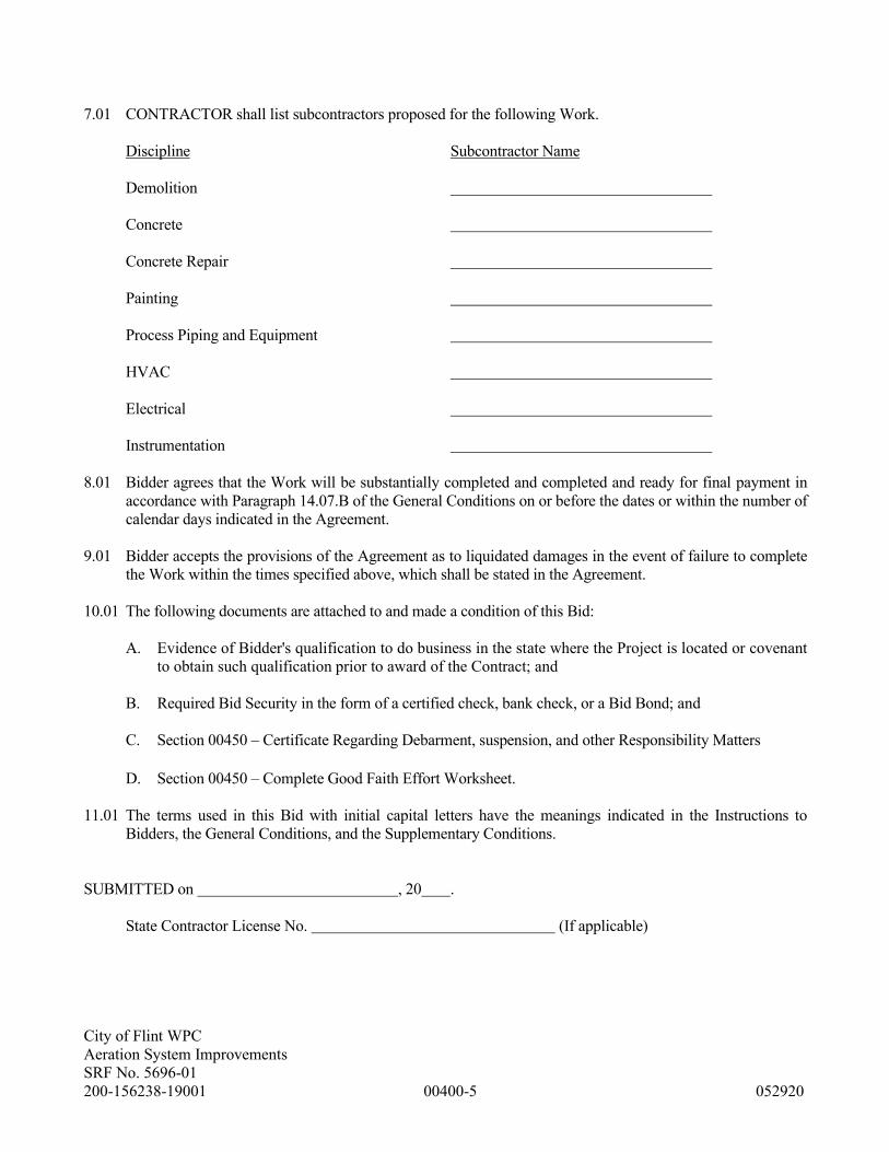
7.01 CONTRACTOR shall list subcontractors proposed for the following Work.
Discipline Subcontractor Name
Demolition
Concrete
Concrete Repair
Painting
Process Piping and Equipment
HVAC
Electrical
Instrumentation
8.01 Bidder agrees that the Work will be substantially completed and completed and ready for final payment in
accordance with Paragraph 14.07.B of the General Conditions on or before the dates or within the number of
calendar days indicated in the Agreement.
9.01 Bidder accepts the provisions of the Agreement as to liquidated damages in the event of failure to complete
the Work within the times specified above, which shall be stated in the Agreement.
10.01 The following documents are attached to and made a condition of this Bid:
A. Evidence of Bidder's qualification to do business in the state where the Project is located or covenant
to obtain such qualification prior to award of the Contract; and
B. Required Bid Security in the form of a certified check, bank check, or a Bid Bond; and
C. Section 00450 – Certificate Regarding Debarment, suspension, and other Responsibility Matters
D. Section 00450 – Complete Good Faith Effort Worksheet.
11.01 The terms used in this Bid with initial capital letters have the meanings indicated in the Instructions to
Bidders, the General Conditions, and the Supplementary Conditions.
SUBMITTED on , 20 .
State Contractor License No. (If applicable)

City of Flint WPC
Aeration System Improvements
SRF No. 5696-01
200-156238-19001 00400-6 052920
If Bidder is:
An Individual
Name (typed or printed):
By: (SEAL)
(Individual’s signature)
Doing business as:
Business address:
Phone No.: FAX No.:
A Partnership
Partnership Name: (SEAL)
By:
(Signature of general partner -- attach evidence of authority to sign)
Name (typed or printed):
Business address:
Phone No.: FAX No.:
A Corporation
Corporation Name: (SEAL)
State of Incorporation:
Type (General Business, Professional, Service, Limited Liability):
By:
(Signature -- attach evidence of authority to sign)
Name (typed or printed):
Title:
(CORPORATE SEAL)
Attest
(Signature of Corporate Secretary)
Business address:
Phone No.: FAX No.:
Date of Qualification to do business is

City of Flint WPC
Aeration System Improvements
SRF No. 5696-01
200-156238-19001 00400-7 052920
A Joint Venture
Joint Venturer Name: (SEAL)
By:
(Signature of joint venture partner -- attach evidence of authority to sign)
Name (typed or printed):
Title:
Business address:
Phone No.: FAX No.:
Joint Venturer Name: (SEAL)
By:
(Signature -- attach evidence of authority to sign)
Name (typed or printed):
Title:
Business address:
Phone No.: FAX No.:
Phone and FAX Number, and Address for receipt of official communications:
(Each joint venturer must sign. The manner of signing for each individual, partnership, and corporation that is a
party to the joint venture should be in the manner indicated above.)
END OF SECTION

PENAL SUM FORM
EJCDC NO. 1910-28-C (1996 Edition)
City of Flint WPC
Aeration System Improvements
SRF No. 5696-01
200-156238-19001 00430-1 052920
BID BOND
BIDDER (Name and Address):
SURETY (Name and Address of Principal Place of Business):
OWNER (Name and Address):
BID
BID DUE DATE:
PROJECT (Brief Description Including Location):
BOND
BOND NUMBER:
DATE (Not later than Bid due date):
PENAL SUM:
(Words) (Figures)
IN WITNESS WHEREOF, Surety and Bidder, intending to be legally bound hereby, subject to the terms printed on
the reverse side hereof, do each cause this Bid Bond to be duly executed on its behalf by its authorized officer,
agent, or representative.
BIDDER SURETY
(Seal) (Seal)
Bidder's Name and Corporate Seal Surety's Name and Corporate Seal
By: By:
Signature and Title Signature and Title
(Attach Power of Attorney)
Attest: Attest:
Signature and Title Signature and Title
Note: (1) Above addresses are to be used for giving required notice.
(2) Any singular reference to Bidder, Surety, OWNER or other party shall be considered plural where
applicable.

PENAL SUM FORM
EJCDC NO. 1910-28-C (1996 Edition)
City of Flint WPC
Aeration System Improvements
SRF No. 5696-01
200-156238-19001 00430-2 052920
1. Bidder and Surety, jointly and severally, bind
themselves, their heirs, executors, administrators,
successors and assigns to pay to OWNER upon default
of Bidder the penal sum set forth on the face of this
Bond.
2. Default of Bidder shall occur upon the failure of
Bidder to deliver within the time required by the Bidding
Documents (or any extension thereof agreed to in writing
by OWNER) the executed Agreement required by the
Bidding Documents and any performance and payment
Bonds required by the Bidding Documents.
3. This obligation shall be null and void if:
3.1. OWNER accepts Bidder's Bid and Bidder
delivers within the time required by the Bidding
Documents (or any extension thereof agreed to in writing
by OWNER) the executed Agreement required by the
Bidding Documents and any performance and payment
Bonds required by the Bidding Documents, or
3.2. All Bids are rejected by OWNER, or
3.3. OWNER fails to issue a Notice of Award to
Bidder within the time specified in the Bidding
Documents (or any extension thereof agreed to in writing
by Bidder and, if applicable, consented to by Surety
when required by Paragraph 5 hereof).
4. Payment under this Bond will be due and payable
upon default by Bidder and within 30 calendar days after
receipt by Bidder and Surety of written notice of default
from OWNER, which notice will be given with
reasonable promptness, identifying this Bond and the
Project and including a statement of the amount due.
5. Surety waives notice of and any and all defenses
based on or arising out of any time extension to issue
Notice of Award agreed to in writing by OWNER and
Bidder, provided that the total time for issuing Notice of
Award including extensions shall not in the aggregate
exceed 120 days from Bid due date without Surety's
written consent.
6. No suit or action shall be commenced under this
Bond prior to 30 calendar days after the notice of default
required in Paragraph 4 above is received by Bidder and
Surety and in no case later than one year after Bid due
date.
7. Any suit or action under this Bond shall be
commenced only in a court of competent jurisdiction
located in the state in which the Project is located.
8. Notices required hereunder shall be in writing and
sent to Bidder and Surety at their respective addresses
shown on the face of this Bond. Such notices may be
sent by personal delivery, commercial courier or by
United States Registered or Certified Mail, return receipt
requested, postage pre-paid, and shall be deemed to be
effective upon receipt by the party concerned.
9. Surety shall cause to be attached to this Bond a
current and effective Power or Attorney evidencing the
authority of the officer, agent or representative who
executed this Bond on behalf of Surety to execute, seal
and deliver such Bond and bind the Surety thereby.
10. This Bond is intended to conform to all applicable
statutory requirements. Any applicable requirement of
any applicable statute that has been omitted from this
Bond shall be deemed to be included herein as if set
forth at length. If any provision of this Bond conflicts
with any applicable statute, then the provision of said
statute shall govern and the remainder of this Bond that
is not in conflict therewith shall continue in full force
and effect.
11. The term "Bid" as used herein includes a Bid, offer
or proposal as applicable.

Rev. 3-2015
REQUIRED STANDARD CONTRACT LANGUAGE: CLEAN WATER STATE REVOLVING FUND AND DRINKING
WATER REVOLVING FUND
• Davis-Bacon/Prevailing Federal Wages, Including Labor Standards Provisions
• Disadvantaged Business Enterprise (DBE) Requirements*
• Debarment/Suspension Certification*
* Bidders should note these sections contain instructions regarding forms/information that must be completed/included with any
submitted bid.

1 Rev. 3/2015
Davis-Bacon/Prevailing Federal Wage Rates P.L. 111-88 requires compliance with the Davis Bacon Act and adherence to the current U.S. Department of Labor Wage Decision. Attention is called to the fact that not less than the minimum salaries and wages as set forth in the Contract Documents (see Wage Decision included herein) must be paid on this project. The Wage Decision, including modifications, must be posted by the Contractor on the job site. A copy of the Federal Labor Standards Provisions is included and is hereby a part of this contract.

"General Decision Number: MI20200083 05/08/2020
Superseded General Decision Number: MI20190083
State: Michigan
Construction Type: Building
County: Genesee County in Michigan.
BUILDING CONSTRUCTION PROJECTS (does not include single family homes or apartments up to and including 4 stories).
Note: Under Executive Order (EO) 13658, an hourly minimum wage of $10.80 for calendar year 2020 applies to all contracts subject to the Davis-Bacon Act for which the contract is awarded (and any solicitation was issued) on or after January 1, 2015. If this contract is covered by the EO, the contractor must pay all workers in any classification listed on this wage determination at least $10.80 per hour (or the applicable wage rate listed on this wage determination, if it is higher) for all hours spent performing on the contract in calendar year 2020. If this contract is covered by the EO and a classification considered necessary for performance of work on the contract does not appear on this wage determination, the contractor must pay workers in that classification at least the wage rate determined through the conformance process set forth in 29 CFR 5.5(a)(1)(ii) (or the EO minimum wage rate,if it is higher than the conformed wage rate). The EO minimum wage rate will be adjusted annually. Please note that this EO applies to the above-mentioned types of contracts entered into by the federal government that are subject to the Davis-Bacon Act itself, but it does not apply to contracts subject only to the Davis-Bacon Related Acts, including those set forth at 29 CFR 5.1(a)(2)-(60). Additional information on contractor requirements and worker protections under the EO is available at www.dol.gov/whd/govcontracts.
Modification Number Publication Date 0 01/03/2020 1 01/24/2020 2 05/08/2020
ASBE0047-002 07/01/2019
Rates Fringes
ASBESTOS WORKER/HEAT & FROST INSULATOR........................$ 31.82 17.88 ---------------------------------------------------------------- BOIL0169-001 03/01/2018
Rates Fringes
BOILERMAKER......................$ 38.65 26.22 ---------------------------------------------------------------- BRMI0009-014 08/01/2019
Rates Fringes
BRICKLAYER.......................$ 33.23 21.28 TILE FINISHER....................$ 29.93 18.02
5/25/2020https://beta.sam.gov/wage-determination/MI20200083/2?index=wd&keywords=&is_activ...
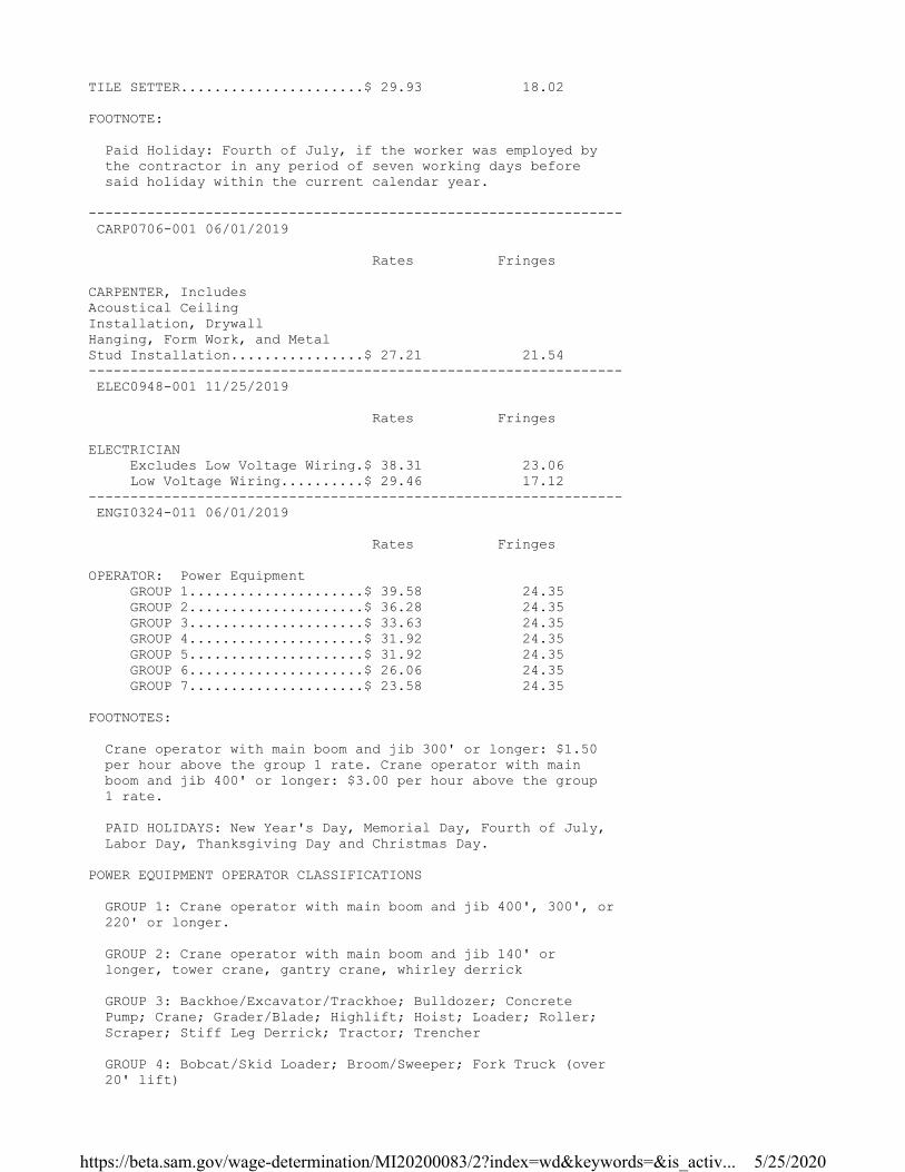
TILE SETTER......................$ 29.93 18.02
FOOTNOTE:
Paid Holiday: Fourth of July, if the worker was employed by the contractor in any period of seven working days before said holiday within the current calendar year.
---------------------------------------------------------------- CARP0706-001 06/01/2019
Rates Fringes
CARPENTER, Includes Acoustical Ceiling Installation, Drywall Hanging, Form Work, and Metal Stud Installation................$ 27.21 21.54 ---------------------------------------------------------------- ELEC0948-001 11/25/2019
Rates Fringes
ELECTRICIAN Excludes Low Voltage Wiring.$ 38.31 23.06 Low Voltage Wiring..........$ 29.46 17.12 ---------------------------------------------------------------- ENGI0324-011 06/01/2019
Rates Fringes
OPERATOR: Power Equipment GROUP 1.....................$ 39.58 24.35 GROUP 2.....................$ 36.28 24.35 GROUP 3.....................$ 33.63 24.35 GROUP 4.....................$ 31.92 24.35 GROUP 5.....................$ 31.92 24.35 GROUP 6.....................$ 26.06 24.35 GROUP 7.....................$ 23.58 24.35
FOOTNOTES:
Crane operator with main boom and jib 300' or longer: $1.50 per hour above the group 1 rate. Crane operator with main boom and jib 400' or longer: $3.00 per hour above the group 1 rate.
PAID HOLIDAYS: New Year's Day, Memorial Day, Fourth of July, Labor Day, Thanksgiving Day and Christmas Day.
POWER EQUIPMENT OPERATOR CLASSIFICATIONS
GROUP 1: Crane operator with main boom and jib 400', 300', or 220' or longer.
GROUP 2: Crane operator with main boom and jib 140' or longer, tower crane, gantry crane, whirley derrick
GROUP 3: Backhoe/Excavator/Trackhoe; Bulldozer; Concrete Pump; Crane; Grader/Blade; Highlift; Hoist; Loader; Roller; Scraper; Stiff Leg Derrick; Tractor; Trencher
GROUP 4: Bobcat/Skid Loader; Broom/Sweeper; Fork Truck (over 20' lift)
5/25/2020https://beta.sam.gov/wage-determination/MI20200083/2?index=wd&keywords=&is_activ...

GROUP 5: Boom Truck (non-swinging)
GROUP 6: Fork Truck (20' lift and under for masonry work)
GROUP 7: Oiler
---------------------------------------------------------------- IRON0025-019 06/01/2019
Rates Fringes
IRONWORKER REINFORCING.................$ 30.98 27.99 STRUCTURAL..................$ 36.77 29.03 ---------------------------------------------------------------- LABO0334-005 06/01/2019
Rates Fringes
LABORER: Landscape & Irrigation GROUP 1.....................$ 20.75 7.10 GROUP 2.....................$ 18.75 7.10
CLASSIFICATIONS
GROUP 1: Landscape specialist, including air, gas and diesel equipment operator, lawn sprinkler installer, skidsteer (or equivalent)
GROUP 2: Landscape laborer: small power tool operator, material mover, truck driver and lawn sprinkler installer tender
---------------------------------------------------------------- LABO1075-002 06/01/2019
Rates Fringes
LABORER Common or General; Grade Checker; Mason Tender - Brick/Cement/Concrete, Pipelayer; Sandblaster......$ 23.00 13.66 ---------------------------------------------------------------- PAIN1052-001 06/01/2018
Rates Fringes
PAINTER Brush & Roler...............$ 24.40 12.95 Spray.......................$ 25.75 12.95 ---------------------------------------------------------------- PAIN1052-004 06/01/2018
Rates Fringes
DRYWALL FINISHER/TAPER Drywall sanding.............$ 26.07 13.50 Hand work...................$ 26.07 13.50 Machine work................$ 26.07 13.50 ---------------------------------------------------------------- PLAS0016-005 04/01/2014
5/25/2020https://beta.sam.gov/wage-determination/MI20200083/2?index=wd&keywords=&is_activ...

Rates Fringes
CEMENT MASON/CONCRETE FINISHER...$ 25.58 12.88 ---------------------------------------------------------------- PLUM0370-002 06/01/2018
Rates Fringes
PIPEFITTER (Includes HVAC Pipe Installation; Excludes HVAC System Installation)........$ 37.81 20.60 PLUMBER, Excludes HVAC Pipe Installation.....................$ 37.81 20.60 ---------------------------------------------------------------- ROOF0149-005 06/01/2019
Rates Fringes
ROOFER...........................$ 28.53 17.53 ---------------------------------------------------------------- * SFMI0669-001 04/01/2020
Rates Fringes
SPRINKLER FITTER (Fire Sprinklers)......................$ 35.72 23.60 ---------------------------------------------------------------- SHEE0007-008 05/01/2018
Rates Fringes
SHEET METAL WORKER, Includes HVAC Duct and Unit Installation.....................$ 30.64 22.76 ---------------------------------------------------------------- SUMI2011-008 02/01/2011
Rates Fringes
IRONWORKER, ORNAMENTAL...........$ 18.48 7.93
TRUCK DRIVER: Tractor Haul Truck............................$ 13.57 1.18 ----------------------------------------------------------------
WELDERS - Receive rate prescribed for craft performing operation to which welding is incidental.
================================================================
Note: Executive Order (EO) 13706, Establishing Paid Sick Leave for Federal Contractors applies to all contracts subject to the Davis-Bacon Act for which the contract is awarded (and any solicitation was issued) on or after January 1, 2017. If this contract is covered by the EO, the contractor must provide employees with 1 hour of paid sick leave for every 30 hours they work, up to 56 hours of paid sick leave each year. Employees must be permitted to use paid sick leave for their own illness, injury or other health-related needs, including preventive care; to assist a family member (or person who is like family to the employee) who is ill, injured, or has other health-related needs, including preventive care; or for reasons resulting from, or to assist a family member (or person who is
5/25/2020https://beta.sam.gov/wage-determination/MI20200083/2?index=wd&keywords=&is_activ...
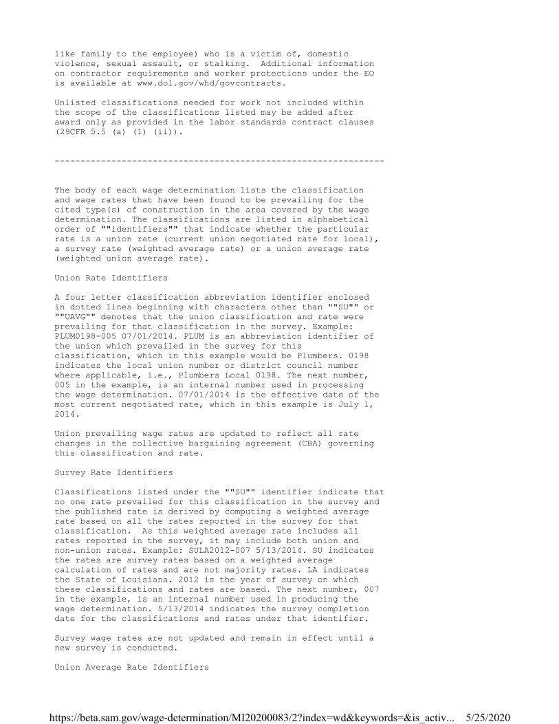
like family to the employee) who is a victim of, domestic violence, sexual assault, or stalking. Additional information on contractor requirements and worker protections under the EO is available at www.dol.gov/whd/govcontracts.
Unlisted classifications needed for work not included within the scope of the classifications listed may be added after award only as provided in the labor standards contract clauses (29CFR 5.5 (a) (1) (ii)).
----------------------------------------------------------------
The body of each wage determination lists the classification and wage rates that have been found to be prevailing for the cited type(s) of construction in the area covered by the wage determination. The classifications are listed in alphabetical order of ""identifiers"" that indicate whether the particular rate is a union rate (current union negotiated rate for local), a survey rate (weighted average rate) or a union average rate (weighted union average rate).
Union Rate Identifiers
A four letter classification abbreviation identifier enclosed in dotted lines beginning with characters other than ""SU"" or ""UAVG"" denotes that the union classification and rate were prevailing for that classification in the survey. Example: PLUM0198-005 07/01/2014. PLUM is an abbreviation identifier of the union which prevailed in the survey for this classification, which in this example would be Plumbers. 0198 indicates the local union number or district council number where applicable, i.e., Plumbers Local 0198. The next number, 005 in the example, is an internal number used in processing the wage determination. 07/01/2014 is the effective date of the most current negotiated rate, which in this example is July 1, 2014.
Union prevailing wage rates are updated to reflect all rate changes in the collective bargaining agreement (CBA) governing this classification and rate.
Survey Rate Identifiers
Classifications listed under the ""SU"" identifier indicate that no one rate prevailed for this classification in the survey and the published rate is derived by computing a weighted average rate based on all the rates reported in the survey for that classification. As this weighted average rate includes all rates reported in the survey, it may include both union and non-union rates. Example: SULA2012-007 5/13/2014. SU indicates the rates are survey rates based on a weighted average calculation of rates and are not majority rates. LA indicates the State of Louisiana. 2012 is the year of survey on which these classifications and rates are based. The next number, 007 in the example, is an internal number used in producing the wage determination. 5/13/2014 indicates the survey completion date for the classifications and rates under that identifier.
Survey wage rates are not updated and remain in effect until a new survey is conducted.
Union Average Rate Identifiers
5/25/2020https://beta.sam.gov/wage-determination/MI20200083/2?index=wd&keywords=&is_activ...

Classification(s) listed under the UAVG identifier indicate that no single majority rate prevailed for those classifications; however, 100% of the data reported for the classifications was union data. EXAMPLE: UAVG-OH-0010 08/29/2014. UAVG indicates that the rate is a weighted union average rate. OH indicates the state. The next number, 0010 in the example, is an internal number used in producing the wage determination. 08/29/2014 indicates the survey completion date for the classifications and rates under that identifier.
A UAVG rate will be updated once a year, usually in January of each year, to reflect a weighted average of the current negotiated/CBA rate of the union locals from which the rate is based.
----------------------------------------------------------------
WAGE DETERMINATION APPEALS PROCESS
1.) Has there been an initial decision in the matter? This can be:
* an existing published wage determination * a survey underlying a wage determination * a Wage and Hour Division letter setting forth a position on a wage determination matter * a conformance (additional classification and rate) ruling
On survey related matters, initial contact, including requests for summaries of surveys, should be with the Wage and Hour Regional Office for the area in which the survey was conducted because those Regional Offices have responsibility for the Davis-Bacon survey program. If the response from this initial contact is not satisfactory, then the process described in 2.) and 3.) should be followed.
With regard to any other matter not yet ripe for the formal process described here, initial contact should be with the Branch of Construction Wage Determinations. Write to:
Branch of Construction Wage Determinations Wage and Hour Division U.S. Department of Labor 200 Constitution Avenue, N.W. Washington, DC 20210
2.) If the answer to the question in 1.) is yes, then an interested party (those affected by the action) can request review and reconsideration from the Wage and Hour Administrator (See 29 CFR Part 1.8 and 29 CFR Part 7). Write to:
Wage and Hour Administrator U.S. Department of Labor 200 Constitution Avenue, N.W. Washington, DC 20210
The request should be accompanied by a full statement of the interested party's position and by any information (wage payment data, project description, area practice material, etc.) that the requestor considers relevant to the issue.
5/25/2020https://beta.sam.gov/wage-determination/MI20200083/2?index=wd&keywords=&is_activ...

3.) If the decision of the Administrator is not favorable, an interested party may appeal directly to the Administrative Review Board (formerly the Wage Appeals Board). Write to:
Administrative Review Board U.S. Department of Labor 200 Constitution Avenue, N.W. Washington, DC 20210
4.) All decisions by the Administrative Review Board are final.
================================================================
END OF GENERAL DECISION"
5/25/2020https://beta.sam.gov/wage-determination/MI20200083/2?index=wd&keywords=&is_activ...

3 Rev. 3/2015
29 CFR Part 5 – Labor Standards Provisions for Federally Assisted Projects
§ 5.5 Contract provisions and related matters. (a) The Agency head shall cause or require the contracting officer to insert in full in any contract in excess of $2,000 which is entered into for the actual construction, alteration and/or repair, including painting and decorating, of a public building or public work, or building or work financed in whole or in part from Federal funds or in accordance with guarantees of a Federal agency or financed from funds obtained by pledge of any contract of a Federal agency to make a loan, grant or annual contribution (except where a different meaning is expressly indicated), and which is subject to the labor standards provisions of any of the acts listed in Sec. 5.1, the following clauses (or any modifications thereof to meet the particular needs of the agency, Provided, That such modifications are first approved by the Department of Labor): (1) Minimum wages. (i) All laborers and mechanics employed or working upon the site of the work (or under the United States Housing Act of 1937 or under the Housing Act of 1949 in the construction or development of the project), will be paid unconditionally and not less often than once a week, and without subsequent deduction or rebate on any account (except such payroll deductions as are permitted by regulations issued by the Secretary of Labor under the Copeland Act (29 CFR part 3)), the full amount of wages and bona fide fringe benefits (or cash equivalents thereof) due at time of payment computed at rates not less than those contained in the wage determination of the Secretary of Labor which is attached hereto and made a part hereof, regardless of any contractual relationship which may be alleged to exist between the contractor and such laborers and mechanics. Contributions made or costs reasonably anticipated for bona fide fringe benefits under section 1(b)(2) of the Davis-Bacon Act on behalf of laborers or mechanics are considered wages paid to such laborers or mechanics, subject to the provisions of paragraph (a)(1)(iv) of this section; also, regular contributions made or costs incurred for more than a weekly period (but not less often than quarterly) under plans, funds, or programs which cover the particular weekly period, are deemed to be constructively made or incurred during such weekly period. Such laborers and mechanics shall be paid the appropriate wage rate and fringe benefits on the wage determination for the classification of work actually performed, without regard to skill, except as provided in Sec. 5.5(a)(4). Laborers or mechanics performing work in more than one classification may be compensated at the rate specified for each classification for the time actually worked therein: Provided, That the employer's payroll records accurately set forth the time spent in each classification in which work is performed. The wage determination (including any additional classification and wage rates conformed under paragraph (a)(1)(ii) of this section) and the Davis-Bacon poster (WH-1321) shall be posted at all times by the contractor and its subcontractors at the site of the work in a prominent and accessible place where it can be easily seen by the workers. (ii)(A) The contracting officer shall require that any class of laborers or mechanics, including helpers, which is not listed in the wage determination and which is to be employed under the contract shall be classified in conformance with the wage determination. The contracting officer shall approve an additional classification and wage rate and fringe benefits therefore only when the following criteria have been met: (1) The work to be performed by the classification requested is not performed by a classification in the wage determination; and

4 Rev. 3/2015
(2) The classification is utilized in the area by the construction industry; and (3) The proposed wage rate, including any bona fide fringe benefits, bears a reasonable relationship to the wage rates contained in the wage determination. (B) If the contractor and the laborers and mechanics to be employed in the classification (if known), or their representatives, and the contracting officer agree on the classification and wage rate (including the amount designated for fringe benefits where appropriate), a report of the action taken shall be sent by the contracting officer to the Administrator of the Wage and Hour Division, Employment Standards Administration, U.S. Department of Labor, Washington, DC 20210. The Administrator, or an authorized representative, will approve, modify, or disapprove every additional classification action within 30 days of receipt and so advise the contracting officer or will notify the contracting officer within the 30-day period that additional time is necessary. (C) In the event the contractor, the laborers or mechanics to be employed in the classification or their representatives, and the contracting officer do not agree on the proposed classification and wage rate (including the amount designated for fringe benefits, where appropriate), the contracting officer shall refer the questions, including the views of all interested parties and the recommendation of the contracting officer, to the Administrator for determination. The Administrator, or an authorized representative, will issue a determination within 30 days of receipt and so advise the contracting officer or will notify the contracting officer within the 30-day period that additional time is necessary. (D) The wage rate (including fringe benefits where appropriate) determined pursuant to paragraphs (a)(1)(ii) (B) or (C) of this section, shall be paid to all workers performing work in the classification under this contract from the first day on which work is performed in the classification. (iii) Whenever the minimum wage rate prescribed in the contract for a class of laborers or mechanics includes a fringe benefit which is not expressed as an hourly rate, the contractor shall either pay the benefit as stated in the wage determination or shall pay another bona fide fringe benefit or an hourly cash equivalent thereof. (iv) If the contractor does not make payments to a trustee or other third person, the contractor may consider as part of the wages of any laborer or mechanic the amount of any costs reasonably anticipated in providing bona fide fringe benefits under a plan or program, Provided, That the Secretary of Labor has found, upon the written request of the contractor, that the applicable standards of the Davis-Bacon Act have been met. The Secretary of Labor may require the contractor to set aside in a separate account assets for the meeting of obligations under the plan or program. (2) Withholding. The (write in name of Federal Agency or the loan or grant recipient) shall upon its own action or upon written request of an authorized representative of the Department of Labor withhold or cause to be withheld from the contractor under this contract or any other Federal contract with the same prime contractor, or any other federally-assisted contract subject to Davis-Bacon prevailing wage requirements, which is held by the same prime contractor, so much of the accrued payments or advances as may be considered necessary to pay laborers and mechanics, including apprentices, trainees, and helpers, employed by the contractor or any subcontractor the full amount of wages required by the contract. In the event of failure to pay any laborer or mechanic, including any apprentice, trainee, or helper, employed or working on the site of the work (or under the United States Housing Act of 1937 or under the Housing Act of

5 Rev. 3/2015
1949 in the construction or development of the project), all or part of the wages required by the contract, the (Agency) may, after written notice to the contractor, sponsor, applicant, or owner, take such action as may be necessary to cause the suspension of any further payment, advance, or guarantee of funds until such violations have ceased. (3) Payrolls and basic records. (i) Payrolls and basic records relating thereto shall be maintained by the contractor during the course of the work and preserved for a period of three years thereafter for all laborers and mechanics working at the site of the work (or under the United States Housing Act of 1937, or under the Housing Act of 1949, in the construction or development of the project). Such records shall contain the name, address, and social security number of each such worker, his or her correct classification, hourly rates of wages paid (including rates of contributions or costs anticipated for bona fide fringe benefits or cash equivalents thereof of the types described in section 1(b)(2)(B) of the Davis-Bacon Act), daily and weekly number of hours worked, deductions made and actual wages paid. Whenever the Secretary of Labor has found under 29 CFR 5.5(a)(1)(iv) that the wages of any laborer or mechanic include the amount of any costs reasonably anticipated in providing benefits under a plan or program described in section 1(b)(2)(B) of the Davis-Bacon Act, the contractor shall maintain records which show that the commitment to provide such benefits is enforceable, that the plan or program is financially responsible, and that the plan or program has been communicated in writing to the laborers or mechanics affected, and records which show the costs anticipated or the actual cost incurred in providing such benefits. Contractors employing apprentices or trainees under approved programs shall maintain written evidence of the registration of apprenticeship programs and certification of trainee programs, the registration of the apprentices and trainees, and the ratios and wage rates prescribed in the applicable programs. (ii)(A) The contractor shall submit weekly for each week in which any contract work is performed a copy of all payrolls to the (write in name of appropriate federal agency) if the agency is a party to the contract, but if the agency is not such a party, the contractor will submit the payrolls to the applicant, sponsor, or owner, as the case may be, for transmission to the (write in name of agency). The payrolls submitted shall set out accurately and completely all of the information required to be maintained under 29 CFR 5.5(a)(3)(i), except that full social security numbers and home addresses shall not be included on weekly transmittals. Instead the payrolls shall only need to include an individually identifying number for each employee (e.g., the last four digits of the employee's social security number). The required weekly payroll information may be submitted in any form desired. Optional Form WH-347 is available for this purpose from the Wage and Hour Division Web site at http://www.dol.gov/whd/forms/wh347.pdf or its successor site. The prime contractor is responsible for the submission of copies of payrolls by all subcontractors. Contractors and subcontractors shall maintain the full social security number and current address of each covered worker, and shall provide them upon request to the (write in name of appropriate federal agency) if the agency is a party to the contract, but if the agency is not such a party, the contractor will submit them to the applicant, sponsor, or owner, as the case may be, for transmission to the (write in name of agency), the contractor, or the Wage and Hour Division of the Department of Labor for purposes of an investigation or audit of compliance with prevailing wage requirements. It is not a violation of this section for a prime contractor to require a subcontractor to provide addresses and social security numbers to the prime contractor for its own records, without weekly submission to the sponsoring government agency (or the applicant, sponsor, or owner). (B) Each payroll submitted shall be accompanied by a ``Statement of Compliance,'' signed by the contractor or subcontractor or his or her agent who pays or supervises the payment of the persons employed under the contract and shall certify the following:

6 Rev. 3/2015
(1) That the payroll for the payroll period contains the information required to be provided under Sec. 5.5 (a)(3)(ii) of Regulations, 29 CFR part 5, the appropriate information is being maintained under Sec. 5.5 (a)(3)(i) of Regulations, 29 CFR part 5, and that such information is correct and complete; (2) That each laborer or mechanic (including each helper, apprentice, and trainee) employed on the contract during the payroll period has been paid the full weekly wages earned, without rebate, either directly or indirectly, and that no deductions have been made either directly or indirectly from the full wages earned, other than permissible deductions as set forth in Regulations, 29 CFR part 3; (3) That each laborer or mechanic has been paid not less than the applicable wage rates and fringe benefits or cash equivalents for the classification of work performed, as specified in the applicable wage determination incorporated into the contract. (C) The weekly submission of a properly executed certification set forth on the reverse side of Optional Form WH-347 shall satisfy the requirement for submission of the ``Statement of Compliance'' required by paragraph (a)(3)(ii)(B) of this section. (D) The falsification of any of the above certifications may subject the contractor or subcontractor to civil or criminal prosecution under section 1001 of title 18 and section 231 of title 31 of the United States Code. (iii) The contractor or subcontractor shall make the records required under paragraph (a)(3)(i) of this section available for inspection, copying, or transcription by authorized representatives of the (write the name of the agency) or the Department of Labor, and shall permit such representatives to interview employees during working hours on the job. If the contractor or subcontractor fails to submit the required records or to make them available, the Federal agency may, after written notice to the contractor, sponsor, applicant, or owner, take such action as may be necessary to cause the suspension of any further payment, advance, or guarantee of funds. Furthermore, failure to submit the required records upon request or to make such records available may be grounds for debarment action pursuant to 29 CFR 5.12. (4) Apprentices and trainees--(i) Apprentices. Apprentices will be permitted to work at less than the predetermined rate for the work they performed when they are employed pursuant to and individually registered in a bona fide apprenticeship program registered with the U.S. Department of Labor, Employment and Training Administration, Office of Apprenticeship Training, Employer and Labor Services, or with a State Apprenticeship Agency recognized by the Office, or if a person is employed in his or her first 90 days of probationary employment as an apprentice in such an apprenticeship program, who is not individually registered in the program, but who has been certified by the Office of Apprenticeship Training, Employer and Labor Services or a State Apprenticeship Agency (where appropriate) to be eligible for probationary employment as an apprentice. The allowable ratio of apprentices to journeymen on the job site in any craft classification shall not be greater than the ratio permitted to the contractor as to the entire work force under the registered program. Any worker listed on a payroll at an apprentice wage rate, who is not registered or otherwise employed as stated above, shall be paid not less than the applicable wage rate on the wage determination for the classification of work actually performed. In addition, any apprentice performing work on the job site in excess of the ratio permitted under the registered program shall be paid not less than the applicable wage rate on the wage determination for the work actually performed. Where a contractor is performing construction on a project in a locality other than that in which its

7 Rev. 3/2015
program is registered, the ratios and wage rates (expressed in percentages of the journeyman's hourly rate) specified in the contractor's or subcontractor's registered program shall be observed. Every apprentice must be paid at not less than the rate specified in the registered program for the apprentice's level of progress, expressed as a percentage of the journeymen hourly rate specified in the applicable wage determination. Apprentices shall be paid fringe benefits in accordance with the provisions of the apprenticeship program. If the apprenticeship program does not specify fringe benefits, apprentices must be paid the full amount of fringe benefits listed on the wage determination for the applicable classification. If the Administrator determines that a different practice prevails for the applicable apprentice classification, fringes shall be paid in accordance with that determination. In the event the Office of Apprenticeship Training, Employer and Labor Services, or a State Apprenticeship Agency recognized by the Office, withdraws approval of an apprenticeship program, the contractor will no longer be permitted to utilize apprentices at less than the applicable predetermined rate for the work performed until an acceptable program is approved. (ii) Trainees. Except as provided in 29 CFR 5.16, trainees will not be permitted to work at less than the predetermined rate for the work performed unless they are employed pursuant to and individually registered in a program which has received prior approval, evidenced by formal certification by the U.S. Department of Labor, Employment and Training Administration. The ratio of trainees to journeymen on the job site shall not be greater than permitted under the plan approved by the Employment and Training Administration. Every trainee must be paid at not less than the rate specified in the approved program for the trainee's level of progress, expressed as a percentage of the journeyman hourly rate specified in the applicable wage determination. Trainees shall be paid fringe benefits in accordance with the provisions of the trainee program. If the trainee program does not mention fringe benefits, trainees shall be paid the full amount of fringe benefits listed on the wage determination unless the Administrator of the Wage and Hour Division determines that there is an apprenticeship program associated with the corresponding journeyman wage rate on the wage determination which provides for less than full fringe benefits for apprentices. Any employee listed on the payroll at a trainee rate who is not registered and participating in a training plan approved by the Employment and Training Administration shall be paid not less than the applicable wage rate on the wage determination for the classification of work actually performed. In addition, any trainee performing work on the job site in excess of the ratio permitted under the registered program shall be paid not less than the applicable wage rate on the wage determination for the work actually performed. In the event the Employment and Training Administration withdraws approval of a training program, the contractor will no longer be permitted to utilize trainees at less than the applicable predetermined rate for the work performed until an acceptable program is approved. (iii) Equal employment opportunity. The utilization of apprentices, trainees and journeymen under this part shall be in conformity with the equal employment opportunity requirements of Executive Order 11246, as amended, and 29 CFR part 30. (5) Compliance with Copeland Act requirements. The contractor shall comply with the requirements of 29 CFR part 3, which are incorporated by reference in this contract. (6) Subcontracts. The contractor or subcontractor shall insert in any subcontracts the clauses contained in 29 CFR 5.5(a)(1) through (10) and such other clauses as the (write in the name of the Federal agency) may by appropriate instructions require, and also a clause requiring the subcontractors to include these clauses in any lower tier subcontracts. The prime contractor shall be responsible for the compliance by any subcontractor or lower tier subcontractor with all the contract clauses in 29 CFR 5.5.

8 Rev. 3/2015
(7) Contract termination: debarment. A breach of the contract clauses in 29 CFR 5.5 may be grounds for termination of the contract, and for debarment as a contractor and a subcontractor as provided in 29 CFR 5.12. (8) Compliance with Davis-Bacon and Related Act requirements. All rulings and interpretations of the Davis-Bacon and Related Acts contained in 29 CFR parts 1, 3, and 5 are herein incorporated by reference in this contract. (9) Disputes concerning labor standards. Disputes arising out of the labor standards provisions of this contract shall not be subject to the general disputes clause of this contract. Such disputes shall be resolved in accordance with the procedures of the Department of Labor set forth in 29 CFR parts 5, 6, and 7. Disputes within the meaning of this clause include disputes between the contractor (or any of its subcontractors) and the contracting agency, the U.S. Department of Labor, or the employees or their representatives. (10) Certification of eligibility. (i) By entering into this contract, the contractor certifies that neither it (nor he or she) nor any person or firm who has an interest in the contractor's firm is a person or firm ineligible to be awarded Government contracts by virtue of section 3(a) of the Davis-Bacon Act or 29 CFR 5.12(a)(1). (ii) No part of this contract shall be subcontracted to any person or firm ineligible for award of a Government contract by virtue of section 3(a) of the Davis-Bacon Act or 29 CFR 5.12(a)(1). (iii) The penalty for making false statements is prescribed in the U.S. Criminal Code, 18 U.S.C. 1001. (b) Contract Work Hours and Safety Standards Act. The Agency Head shall cause or require the contracting officer to insert the following clauses set forth in paragraphs (b)(1), (2), (3), and (4) of this section in full in any contract in an amount in excess of $100,000 and subject to the overtime provisions of the Contract Work Hours and Safety Standards Act. These clauses shall be inserted in addition to the clauses required by Sec. 5.5(a) or 4.6 of part 4 of this title. As used in this paragraph, the terms laborers and mechanics include watchmen and guards. (1) Overtime requirements. No contractor or subcontractor contracting for any part of the contract work which may require or involve the employment of laborers or mechanics shall require or permit any such laborer or mechanic in any workweek in which he or she is employed on such work to work in excess of forty hours in such workweek unless such laborer or mechanic receives compensation at a rate not less than one and one-half times the basic rate of pay for all hours worked in excess of forty hours in such workweek. (2) Violation; liability for unpaid wages; liquidated damages. In the event of any violation of the clause set forth in paragraph (b)(1) of this section the contractor and any subcontractor responsible there for shall be liable for the unpaid wages. In addition, such contractor and subcontractor shall be liable to the United States (in the case of work done under contract for the District of Columbia or a territory, to such District or to such territory), for liquidated damages. Such liquidated damages shall be computed with respect to each individual laborer or mechanic, including watchmen and guards, employed in violation of the clause set forth in paragraph (b)(1) of this section, in the sum of $10 for each calendar day on which such individual was required or permitted to work in excess of the standard workweek of forty hours without payment of the overtime wages required by the clause set forth in paragraph (b)(1) of this section.

9 Rev. 3/2015
(3) Withholding for unpaid wages and liquidated damages. The (write in the name of the Federal agency or the loan or grant recipient) shall upon its own action or upon written request of an authorized representative of the Department of Labor withhold or cause to be withheld, from any moneys payable on account of work performed by the contractor or subcontractor under any such contract or any other Federal contract with the same prime contractor, or any other federally-assisted contract subject to the Contract Work Hours and Safety Standards Act, which is held by the same prime contractor, such sums as may be determined to be necessary to satisfy any liabilities of such contractor or subcontractor for unpaid wages and liquidated damages as provided in the clause set forth in paragraph (b)(2) of this section. (4) Subcontracts. The contractor or subcontractor shall insert in any subcontracts the clauses set forth in paragraph (b)(1) through (4) of this section and also a clause requiring the subcontractors to include these clauses in any lower tier subcontracts. The prime contractor shall be responsible for compliance by any subcontractor or lower tier subcontractor with the clauses set forth in paragraphs (b)(1) through (4) of this section. (c) In addition to the clauses contained in paragraph (b), in any contract subject only to the Contract Work Hours and Safety Standards Act and not to any of the other statutes cited in Sec. 5.1, the Agency Head shall cause or require the contracting officer to insert a clause requiring that the contractor or subcontractor shall maintain payrolls and basic payroll records during the course of the work and shall preserve them for a period of three years from the completion of the contract for all laborers and mechanics, including guards and watchmen, working on the contract. Such records shall contain the name and address of each such employee, social security number, correct classifications, hourly rates of wages paid, daily and weekly number of hours worked, deductions made, and actual wages paid. Further, the Agency Head shall cause or require the contracting officer to insert in any such contract a clause providing that the records to be maintained under this paragraph shall be made available by the contractor or subcontractor for inspection, copying, or transcription by authorized representatives of the (write the name of agency) and the Department of Labor, and the contractor or subcontractor will permit such representatives to interview employees during working hours on the job.

10 Rev. 3/2015
Disadvantaged Business Enterprises (DBE) Prime contractors bidding on this project must follow, document, and maintain documentation of their Good Faith Efforts, as listed below, to ensure that Disadvantaged Business Enterprises (DBEs) have the opportunity to participate in the project by increasing DBE awareness of procurement efforts and outreach. Bidders must make the following Good Faith Efforts for any work that will be subcontracted.
1. Ensure DBEs are made aware of contracting opportunities to the fullest extent practicable through outreach and recruitment activities. Place DBEs on solicitation lists and solicit DBEs whenever they are potential sources.
2. Make information on forthcoming opportunities available to DBEs. Arrange time-
frames for contracts and establish delivery schedules, where the requirements permit, in a way that encourages and facilitates participation by DBEs in the competitive process. Whenever possible, post solicitation for bids or proposals for a minimum of 30 calendar days before the bid or proposal closing date. The DBEs should be given a minimum of 5 days to respond to the posting.
3. Consider in the contracting process whether firms competing for large contracts can
be subcontracted with DBEs. Divide total requirements, when economically feasible, into smaller tasks or quantities to permit maximum participation by DBEs in the competitive process.
4. Encourage contracting with a consortium of DBEs when a contract is too large for
one DBE firm to handle individually.
5. Use the services and assistance of the Small Business Administration and the Minority Business Development Agency of the U.S. Department of Commerce.
Subsequent to compliance with the Good Faith Efforts, the following conditions also apply under the DBE requirements. Completed Good Faith Efforts Worksheets (Attachment 1), along with the required supporting documentation outlined in the instructions, must be submitted with your bid proposal. EPA form 6100-2 must also be provided at the pre-bid meeting. A copy of this form is available on the Forms and Guidance page of the Revolving Loan website.
1. The prime contractor must pay its subcontractor for work that has been satisfactorily completed no more than 30 days from the prime contractor’s receipt of payment from the owner.
2. The prime contractor must notify the owner in writing prior to the termination of any
DBE subcontractor for convenience by the prime contractor and employ the Good Faith Efforts if soliciting a replacement contractor.
3. If a DBE contractor fails to complete work under the subcontract for any reason, the
prime contractor must employ the Good Faith Efforts if soliciting a replacement contractor.
4. The prime contractor must employ the Good Faith Efforts.

11 Rev. 3/2015
Debarment Certification
The prime contractor must provide a completed Certification Regarding Debarment, Suspension, and Other Responsibility Matters Form with its bid or proposal package to the owner (Attachment 2).

Attachment 1
Disadvantaged Business Enterprise (DBE) Utilization GOOD FAITH EFFORTS WORKSHEET


Michigan Department of Environmental Quality Office of Drinking Water and Municipal Assistance– Revolving Loan Section
Disadvantaged Business Enterprise (DBE) Utilization State Revolving Fund/Drinking Water Revolving Fund
GOOD FAITH EFFORTS WORKSHEET
Rick Snyder, Governor Dan Wyant, Director
Authorized under Parts 53 & 54 of the Natural Resources and Environmental Protection Act, 1994 PA 451, as amended. www.michigan.gov/deq
Bidder:______________________________________________________________________ Subcontract Area of Work (one per worksheet:_______________________________________________ Outreach Goal: Solicit a minimum of three (3) DBEs via email/letter/fax. It is recommended that various sources be used to locate the minimum number of DBEs. The Michigan Department of Transportation (MDOT) website and www.sam.gov registries may be two resources used to find a minimum of three DBEs. List the DBEs contacted for the above area of work and complete the following information for each DBE.
Company Name Type of Contact
Date of Contact
Price Quote Received
Accepted/ Rejected
Please Explain if Rejected
A R
A R
A R
A R
A R
A R
Explanation for Not Achieving a Minimum of Three Contacts; you may include a printout of the MDOT and www.sam.gov search results (attach extra sheets if necessary): MITA DBE Posting Date (if applicable): _____________________________ (attach a copy of the DBE advertisement) Other Efforts (attach extra sheets if necessary):
Please include the completed worksheet and supporting documentation with the bid proposal. Rev.3-2015

Michigan Department of Environmental Quality Office of Drinking Water and Municipal Assistance– Revolving Loan Section
Disadvantaged Business Enterprise (DBE) Utilization State Revolving Fund/Drinking Water Revolving Fund
GOOD FAITH EFFORTS WORKSHEET
Rick Snyder, Governor Dan Wyant, Director
Authorized under Parts 53 & 54 of the Natural Resources and Environmental Protection Act, 1994 PA 451, as amended. www.michigan.gov/deq
Instructions to Bidders for the Completion of the Good Faith Efforts Worksheet
1. Separate worksheets must be provided for each area of work to be subcontracted out. This includes both major and minor subcontracts.
2. A minimum of three (3) DBEs must be contacted by a verifiable means of communication such as
e-mail, letter, or fax for each area of work to be subcontracted out. Copies of the solicitation letters/e-mails and fax confirmation sheets must be provided with the worksheet.
3. If less that three (3) DBEs exist statewide for the area of work, then provide documentation that
other DBE resources were consulted. This may include the MDOT and www.sam.gov registries and an advertisement is a publication. A printout of the website searched (conducted prior to the end of the bid period) must be submitted.
4. Posting solicitations for quotes/proposals from DBEs on the MITA website (www.mitadbe.com)
is highly recommended to facilitate participation in the competitive process whenever possible. The solicitation needs to identify the project and the areas of work to be subcontracted out. A copy of the MITA DBE advertisement must be submitted with the Good Faith Efforts worksheet, if used, or a printout of the resulting quotes posted to the MITA website can be submitted with this form as supporting documentation.
5. If the area of work is so specialized that no DBEs exist, then an explanation is required to support
that conclusion, including the documentation required in No. 3 above. 6. The date of the DBE contact must be identified, as it is important to document that the DBE
solicitation was made during the bid period and that sufficient time was given for the DBE to return a quote.
7. Each DBE firm’s price quote must be identified if one was received or N/A entered on the
worksheet if a quote was not received. Copies of all quotes must be submitted with the worksheet.
8. If a quote was received, indicate if it was accepted or rejected. Justification for not accepting a
quote and not using the DBE subcontractor must be provided. 9. Under Other Efforts, please indicate additional steps you have taken to obtain DBE contractors
and provide the appropriate supporting documentation such as: • Follow-up e-mails, faxes, or letters. • Copies of announcements/postings in newspapers, trade publications, or minority media that
target DBE firms.
Rev. 3-2015

Attachment 2
Certification Regarding Debarment, Suspension, and Other Responsibility Matters

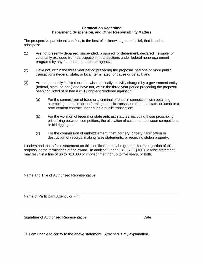
Certification Regarding Debarment, Suspension, and Other Responsibility Matters
The prospective participant certifies, to the best of its knowledge and belief, that it and its principals: (1) Are not presently debarred, suspended, proposed for debarment, declared ineligible, or
voluntarily excluded from participation in transactions under federal nonprocurement programs by any federal department or agency;
(2) Have not, within the three year period preceding the proposal, had one or more public
transactions (federal, state, or local) terminated for cause or default; and (3) Are not presently indicted or otherwise criminally or civilly charged by a government entity
(federal, state, or local) and have not, within the three year period preceding the proposal, been convicted of or had a civil judgment rendered against it:
(a) For the commission of fraud or a criminal offense in connection with obtaining,
attempting to obtain, or performing a public transaction (federal, state, or local) or a procurement contract under such a public transaction;
(b) For the violation of federal or state antitrust statutes, including those proscribing
price fixing between competitors, the allocation of customers between competitors, or bid rigging; or
(c) For the commission of embezzlement, theft, forgery, bribery, falsification or
destruction of records, making false statements, or receiving stolen property. I understand that a false statement on this certification may be grounds for the rejection of this proposal or the termination of the award. In addition, under 18 U.S.C. §1001, a false statement may result in a fine of up to $10,000 or imprisonment for up to five years, or both. _____________________________________________________________________________ Name and Title of Authorized Representative _____________________________________________________________________________ Name of Participant Agency or Firm _____________________________________________________________________________ Signature of Authorized Representative Date I am unable to certify to the above statement. Attached is my explanation.


Attachment 3
Frequently Asked Questions About Disadvantaged Business Enterprise (DBE) Solicitation


Disadvantaged Business Enterprise (DBE) Requirements Frequently Asked Questions Regarding Contractor Compliance
Q: What is the Good Faith Efforts Worksheet form and how is it to be completed? A: This form captures efforts by the prime contractor to solicit DBEs for each area of work type
that will be subcontracted out. A separate Good Faith Efforts Worksheet must be provided by the prime contractor for each area of work type to be subcontracted out. There are specific instructions that accompany this form that prescribe minimum efforts which bidders must make in order to be in compliance with the DBE requirements.
Q: Can non-certified DBEs be used? A: While non-certified DBEs can be used, only DBEs, MBEs, and WBEs that are certified by
EPA, SBA, or MDOT (or by tribal, state and local governments, as long as their standards for certification meet or exceed the standards in EPA policy) can be counted toward the fair share goal. Proof of certification by one of these recognized and approved agencies should be sought from each DBE.
Q: How does a DBE get certified? A: Applications for certification under MDOT can be found at
http://mdotjboss.state.mi.us/UCP/LearnHowServlet.
Applications for certification under EPA can be found on EPA’s Small Business Programs website at http://www.epa.gov/osbp/dbe_firm.htm under Certification Forms.
Q: If a bidder follows the MDOT DBE requirements, will the bidder be in compliance with the
SRF/DWRF DBE requirements? A: No. Federally funded highway projects utilize DBE goals, which require that a certain
percentage of work be performed by DBE subcontractors. For SRF/DWRF projects, there is no financial goal. However, there is a solicitation effort goal. Bidders must use Good Faith Efforts for each and every area of work to be subcontracted out to obtain DBEs. The bidders are not required to use DBEs if the quotes are higher than non-DBE subcontractors. There is no required DBE participation percentage contract goal for the SRF/DWRF. However, if the SRF/DWRF project is part of a joint project with MDOT, the project can be excluded from SRF/DWRF DBE requirements (i.e., the Good Faith Efforts Worksheet is not required) as it would be difficult to comply with both programs’ requirements.
Q. Must the Good Faith Efforts Worksheet and supporting documentation be turned in with the
bid proposals? A: Yes. This is a requirement to document that the contractor has complied with the DBE
requirements and the Good Faith Efforts. These compliance efforts must be done during the bidding phase and not after-the-fact. It is highly recommended that the need for these efforts and the submittal of the forms with the bid proposals be emphasized at the pre-bid meetings. Failure to show that the Good Faith Efforts were complied with during the bidding process can lead to a prime contractor being found non-responsive.
Q: Does EPA form 6100-2 need to be provided at the pre-bid meeting?
A: Yes. The form must be made available at the pre-bid meeting.

Q: What kinds of documentation should a contractor provide to document solicitation efforts? A: Documentation can include fax confirmation sheets, copies of solicitation letters/e-mails,
printouts of online solicitations, printouts of online search results, affidavits of publication in newspapers, etc.
Q: How much time will compliance with the Good Faith Efforts require in terms of structuring an
adequate bidding period? A: Due to the extent of the efforts required, a minimum of 30 calendar days is recommended
between bid posting and bid opening to ensure adequate time for contractors to locate certified DBEs and solicit quotes.
Q: How does a contractor locate certified DBEs? A: The Michigan Department of Transportation has a directory of all Michigan certified entities
located at http://mdotjboss.state.mi.us/UCP/. Additionally, the federal System for Award Management (SAM) is another place to search and can be found at www.sam.gov. SAM contains information from the former Central Contractor Registration (CCR) database.
Q: If the bidder does not intend to subcontract any work, what forms, if any, must be provided
with the bid proposal? A: The bidder should complete the Good Faith Efforts Worksheet with a notation that no
subcontracting will be done. However, if the bidder is awarded the contract and then decides to subcontract work at any point, then the Good Faith Efforts must be made to solicit DBEs.
Q: In the perfect world, the Good Faith Efforts Worksheet is required to be turned in with the
proposal. What if no forms are turned in with the bid proposal or forms are blank or incomplete? Should this be cause to determine that the bidder is non-responsive?
A: While the Good Faith Efforts Worksheet is important, it is more critical to confirm that the
contractor complied with the DBE requirements prior to bid opening. The owner should contact the bidder as soon as deficiencies are noted for a determination/documentation of efforts taken to comply with the DBE requirements. Immediate submittal of the completed forms will be acceptable provided the Good Faith Efforts were made and it is just a matter of transferring information to the forms.
Q: If the prime contractor is a DBE, does he have to solicit DBE subcontractors? A: Yes, the DBE requirements still apply if the prime intends to subcontract work out. Good
Faith Efforts must be used to solicit DBEs. Q: If the area of work is one where there are less than three DBE contractors, how is the
contractor to document this? A: Copies of printouts from MDOT and SAM showing no DBEs and advertisements soliciting
quotes for all subcontract areas, including the questionable areas, will be adequate if the dates on the printouts are prior to the bid or proposal closing date.

City of Flint WPC
Aeration System Improvements
SRF No. 5696-01
200-156238-19001 00458-1 052920
SECTION 00458 – AMERICAN IRON AND STEEL CONTRACT LANGUAGE
The Contractor acknowledges to and for the benefit of the city of Flint (“Purchaser”) and the Michigan
Department of Environment, Great Lakes, and Energy (the “State”) that it understands the goods and services
under this Agreement are being funded with monies made available by the State Revolving Fund and/or the
Drinking Water Revolving Fund and such law contains provisions commonly known as “American Iron and
Steel (AIS);” that requires all iron and steel products used in the project be produced in the United States (“AIS
Requirements”) including iron and steel provided by the Contractor pursuant to this Agreement. The Contractor
hereby represents and warrants to and for the benefit of the Purchaser and the State that (a) the Contractor has
reviewed and understands the AIS Requirements, (b) all iron and steel used in the project will be and/or have
been produced in the United States in a manner that complies with the AIS Requirements, unless a waiver of the
requirements is approved or the State made the determination in writing that the AIS Requirements do not apply
to the project, and (c) the Contractor will provide any further verified information, certification or assurance of
compliance with this paragraph, or information necessary to support a waiver of the AIS requirements, as may
be requested by the Purchaser. Notwithstanding any other provision of this Agreement, any failure to comply
with this paragraph by the Contractor shall permit the Purchaser or State to recover as damages against the
Contractor any loss, expense or cost (including without limitation attorney’s fees) incurred by the Purchaser or
State resulting from any such failure (including without limitation any impairment or loss of funding, whether in
whole or in part, from the State or any damages owed to the State by the Purchaser). While the Contractor has
no direct contractual privity with the State, as a lender to the Purchaser for the funding of its project, the
Purchaser and the Contractor agree that the State is a third-party beneficiary and neither this paragraph (nor any
other provision of this Agreement necessary to give this paragraph force or effect) shall be amended or waived
without the prior written consent of the State.
END OF SECTION

City of Flint WPC
Aeration System Improvements
SRF No. 5696-01
200-156238-19001 00500-1 052920
SECTION 00500 - AGREEMENT
THIS AGREEMENT is by and between City of Flint, MI
(hereinafter called OWNER) and
(hereinafter called CONTRACTOR).
OWNER and CONTRACTOR, in consideration of the mutual covenants hereinafter set forth, agree as follows:
ARTICLE 1 - WORK
1.01 CONTRACTOR shall complete all Work as specified or indicated in the Contract Documents. The Work is
generally described as follows:
A. The Work consists of improvements to the aeration system at the City of Flint Water Pollution Control
Facility. The works includes installation of three new aeration blowers. Also includes installation of a
low energy mixing system in secondary treatment influent and effluent channels, portions of the
Battery B Aeration tanks and primary tank influent channels. The works also includes installation of
fine bubble diffuser equipment in one tank of the Battery B aeration system, replacement of valves,
piping and instrumentation within the Aeration Tank Galleries, replacement and removal of a number
of existing channel gates, concrete repairs to the existing structures, and electrical and instrumentation
improvements.
ARTICLE 2 - THE PROJECT
2.01 The Project for which the Work under the Contract Documents may be the whole or only a part is generally
described as follows:
City of Flint
Water Pollution Control
Aeration System Improvements
SRF No. 5696-01
Contract 200-156238-19001
ARTICLE 3 - ENGINEER
3.01 The Project has been designed by Tetra Tech, Inc., 401 South Washington Square Suite 100, Lansing, MI
48933, who is hereinafter called ENGINEER and who is to act as OWNER’s representative, assume all
duties and responsibilities, and have the rights and authority assigned to ENGINEER in the Contract
Documents in connection with the completion of the Work in accordance with the Contract Documents.
ARTICLE 4 - CONTRACT TIMES
4.01 Time of the Essence

City of Flint WPC
Aeration System Improvements
SRF No. 5696-01
200-156238-19001 00500-2 052920
A. All time limits for Milestones, if any, Substantial Completion, and completion and readiness for final
payment as stated in the Contract Documents are of the essence of the Contract.
4.02 Days to Achieve Substantial Completion and Final Payment
A. The Work will be substantially completed within 600 days after the date when the Contract Times
commence to run as provided in Paragraph 2.03 of the General Conditions, and completed and ready
for final payment in accordance with Paragraph 14.07 of the General Conditions within 630 days after
the date when the Contract Times commence to run.
4.03 Liquidated Damages
A. CONTRACTOR and OWNER recognize that time is of the essence of this Agreement and that
OWNER will suffer financial loss if the Work is not completed within the times specified in Paragraph
4.02 above, plus any extensions thereof allowed in accordance with Article 12 of the General
Conditions. The parties also recognize the delays, expense, and difficulties involved in proving in a
legal or arbitration proceeding the actual loss suffered by OWNER if the Work is not completed on
time. Accordingly, instead of requiring any such proof, OWNER and CONTRACTOR agree that as
liquidated damages for delay (but not as a penalty), CONTRACTOR shall pay OWNER one thousand
dollars ($1,000) for each day that expires after the time specified in Paragraph 4.02 for Substantial
Completion until the Work is substantially complete. After Substantial Completion, if CONTRACTOR
shall neglect, refuse, or fail to complete the remaining Work within the Contract Time or any proper
extension thereof granted by OWNER, CONTRACTOR shall pay OWNER one thousand dollars
($1,000) for each day that expires after the time specified in Paragraph 4.02 for completion and
readiness for final payment until the Work is completed and ready for final payment.
ARTICLE 5 - CONTRACT PRICE
5.01 OWNER will pay CONTRACTOR for completion of the Work in accordance with the Contract Documents
an amount in current funds equal to the sum of the amounts determined pursuant to this Paragraph 5.01 in
the amount listed below:
A. For all Work, a Lump Sum of:
($_______________)
(use words) (figure)
B. All specific allowances are included in the price(s) set forth above and have been computed in
accordance with Paragraph 11.02 of the General Conditions.
1. Included in the Bid Price is a Lump Sum Allowance for WPC system integration programming in
the amount of $ 150,000.
2. Included in the Bid Price is a Lump Sum Allowance for Unforeseen Conditions in the amount of
$125,000.
C. All specific OWNER selected alternates listed below are included in the price(s) set forth above and
have been computed in accordance with Paragraph 11.01 of the General Conditions.
1. Alternate No. 1 (deduct) $_________________

City of Flint WPC
Aeration System Improvements
SRF No. 5696-01
200-156238-19001 00500-3 052920
2. Alternate No. 2 (deduct) $_________________
D. Lump Sum Price Adjustments have been established for this Contract. If increases or decreases in
these quantities occur, the Contract Price is to be adjusted by Change Order on the basis of the
following:
Item and Location
in Specifications
Number of Units to
be Included with Bid
Unit for
Adjustment
Adjustment Price
Per Unit
Pipe Gasket Replacement
6”-10” Diameter 10 Ea
12”-18” Diameter 20 Ea
20”-36” Diameter 10 Ea
Wall Penetration Repair
20” Diameter 10 Ea
Pipe Wall Repair
12”-18” Diameter 10 Sft
20”-36” Diameter 10 Sft
Concrete Repair
Concrete Repair, Type A 20,000 Ft
Concrete Repair, Type B 60 Cft
Concrete Repair, Type C 100 Cft
1. Adjustment prices are subject to acceptance by OWNER, and rejections of one or more
adjustment prices will not invalidate acceptance of this Bid.
2. Bidder acknowledges that estimated quantities are not guaranteed, and are solely for the
purpose of comparison of Bids, and final payment for all Unit Price Bid items will be based on
actual quantities provided, determined as provided in the Contract Documents.
E. All specific allowances are included in the above price and have been computed in accordance with
Paragraph 11.02 of the General Conditions.
F. All specific OWNER-selected alternates are included in the price(s) set forth above, and have been
computed in accordance with Paragraph 11.01 of the General Conditions.
ARTICLE 6 - PAYMENT PROCEDURES
6.01 Submittal and Processing of Payments
A. CONTRACTOR shall submit Applications for Payment in accordance with Article 14 of the General
Conditions. Applications for Payment will be processed by ENGINEER as provided in the General
Conditions.
6.02 Retainage
A. OWNER will make progress payments on account of the Contract Price on the basis of
CONTRACTOR’s Applications for Payment in accordance with Paragraph 14.02.C of the General
Conditions during performance of the Work as provided in Paragraph 6.02.A.1 below. All such

City of Flint WPC
Aeration System Improvements
SRF No. 5696-01
200-156238-19001 00500-4 052920
payments will be measured by the schedule of values established in Paragraph 2.07.A of the General
Conditions (and in the case of Unit Price Work based on the number of units completed) or, in the
event there is no schedule of values, as provided in the General Requirements:
1. The provisions set forth in Michigan Public Acts of 1980, Act No. 524, shall be adhered to by
OWNER and CONTRACTOR for retainage. A copy of the Act is included in Section 00615,
Act No. 524, Michigan P.A. 1980.
2. The OWNER shall pay up to 70 percent on equipment and material that has been delivered to the
site but is not yet installed. Items shall be properly stored per manufacturers guidelines.
3. The OWNER shall pay up to 90 percent on equipment and material that has been installed but is
not yet operational.
6.03 Final Payment
A. Upon final completion and acceptance of the Work in accordance with Paragraph 14.07 of the General
Conditions, OWNER shall pay the remainder of the Contract Price as recommended by ENGINEER as
provided in said Paragraph 14.07.
ARTICLE 7 - INTEREST
7.01 All moneys not paid when due as provided in Article 14 of the General Conditions shall bear interest at
the prevailing passbook savings rate at the place of the Project.
ARTICLE 8 - CONTRACTOR’S REPRESENTATIONS
8.01 In order to induce OWNER to enter into this Agreement CONTRACTOR makes the following
representations:
A. CONTRACTOR has examined and carefully studied the Contract Documents and the other related
data identified in the Bidding Documents.
B. CONTRACTOR has visited the Site and become familiar with and is satisfied as to the general, local,
and Site conditions that may affect cost, progress, and performance of the Work.
C. CONTRACTOR is familiar with and is satisfied as to all Federal, State, and local Laws and
Regulations that may affect cost, progress, and performance of the Work.
D. CONTRACTOR has carefully studied all:
1. Reports of explorations and tests of subsurface conditions at or contiguous to the Site and all
drawings of physical conditions in or relating to existing surface or subsurface structures at or
contiguous to the Site (except Underground Facilities) which have been identified in the
Supplementary Conditions as provided in Paragraph 4.02 of the General Conditions, and
2. Reports and drawings of a Hazardous Environmental Condition, if any, at the Site which has been
identified in the Supplementary Conditions as provided in Paragraph 4.06 of the General
Conditions.
E. CONTRACTOR has obtained and carefully studied (or assumes responsibility for having done so) all
additional or supplementary examinations, investigations, explorations, tests, studies, and data

City of Flint WPC
Aeration System Improvements
SRF No. 5696-01
200-156238-19001 00500-5 052920
concerning conditions (surface, subsurface, and Underground Facilities) at or contiguous to the Site
which may affect cost, progress, or performance of the Work or which relate to any aspect of the
means, methods, techniques, sequences, and procedures of construction to be employed by
CONTRACTOR, including applying the specific means, methods, techniques, sequences, and
procedures of construction, if any, expressly required by the Contract Documents to be employed by
CONTRACTOR, and safety precautions and programs incident thereto
F. CONTRACTOR does not consider that any further examinations, investigations, explorations, tests,
studies, or data are necessary for the performance of the Work at the Contract Price, within the
Contract Times, and in accordance with the other terms and conditions of the Contract Documents.
G. All claims and disputes arising from related Work at Site by other contractors shall be settled in
accordance with Paragraph 7.03 of the Supplementary Conditions.
H. CONTRACTOR has correlated the information known to CONTRACTOR, information and
observations obtained from visits to the Site, reports and drawings identified in the Contract
Documents, and all additional examinations, investigations, explorations, tests, studies, and data with
the Contract Documents.
I. CONTRACTOR has given ENGINEER written notice of all conflicts, errors, ambiguities, or
discrepancies that CONTRACTOR has discovered in the Contract Documents, and the written
resolution thereof by ENGINEER is acceptable to CONTRACTOR.
J. The Contract Documents are generally sufficient to indicate and convey understanding of all terms and
conditions for performance and furnishing of the Work.
K. CONTRACTOR acknowledges that it shall not discriminate against any employee or applicant for
employment with respect to hire, tenure, conditions, or privileges of employment, or a matter directly
or indirectly related to employment, because of race, color, religion, national origin, age, sex, height,
weight, marital status, or a disability that can be reasonable accommodated. OWNER will require this
covenant be placed in the Contract with any subcontractor employed in the performance of this
Contract. A breach of this covenant shall be regarded as a material breach of the Contract.
L. OWNER will require the use of prevailing wage rates on this Project. CONTRACTOR must comply
with:
1. Section 00450 - Prevailing Wage Rates, General Decision Number MI20200083, dated
05/08/2020.
2. Section 00458 – Buy American Contract Language
ARTICLE 9 - CONTRACT DOCUMENTS
9.01 Contents
A. The Contract Documents consist of the following:
1. This Agreement (Pages 00500-1 to ______, inclusive);
2. Performance Bond (Pages 00613-1 to 2, inclusive);
3. Payment Bond (Pages 00614-1 to 2, inclusive);

City of Flint WPC
Aeration System Improvements
SRF No. 5696-01
200-156238-19001 00500-6 052920
4. General Conditions (Pages 00700-1 to _____, inclusive);
5. Supplementary Conditions (Pages 00800-1 to _____, inclusive);
6. Specifications as listed in the table of contents of the Project Manual;
7. Drawings consisting of a cover sheet and sheets enumerated as follows:
Volume I Drawing No. Volume II Drawing No.
General G-1 through _____, inclusive Pipework P-1 through _____, inclusive
Architectural A-1 through _____, inclusive Mechanical M-1 through _____, inclusive
Structural S-1 through _____, inclusive
Volume III Drawing No.
Electrical E-1 through _____, inclusive
Instrumentation I-1 through _____, inclusive
With each sheet bearing the following general title:
City of Flint
Water Pollution Control
Aeration System Improvements
SRF No. 5696-01
Contract 200-156238-19001
7. Addenda (numbers _____ to _____, inclusive);
8. Exhibits to this Agreement (enumerated as follows):
a. Notice to Proceed (Page 00550-1);
b. CONTRACTOR’s Bid (Pages 00400-1 to _____, inclusive);
c. Documentation submitted by CONTRACTOR prior to Notice of Award (pages _____ to
_____, inclusive);
d. ___________________________________________________________;
9. The following which may be delivered or issued on or after the Effective Date of the Agreement
and are not attached hereto:
a. Written Amendments;
b. Work Change Directives;
c. Change Order(s).
B. The documents listed in Paragraph 9.01.A are attached to this Agreement (except as expressly noted
otherwise above).
C. There are no Contract Documents other than those listed above in this Article 9.
D. The Contract Documents may only be amended, modified, or supplemented as provided in Paragraph
3.04 of the General Conditions.

City of Flint WPC
Aeration System Improvements
SRF No. 5696-01
200-156238-19001 00500-7 052920
ARTICLE 10 - MISCELLANEOUS
10.01 Terms
A. Terms used in this Agreement will have the meanings indicated in the General Conditions.
10.02 Assignment of Contract
A. No assignment by a party hereto of any rights under or interests in the Contract will be binding on
another party hereto without the written consent of the party sought to be bound; and, specifically but
without limitation, moneys that may become due and moneys that are due may not be assigned without
such consent (except to the extent that the effect of this restriction may be limited by law), and unless
specifically stated to the contrary in any written consent to an assignment, no assignment will release
or discharge the assignor from any duty or responsibility under the Contract Documents.
10.03 Successors and Assigns
A. OWNER and CONTRACTOR each binds itself, its partners, successors, assigns, and legal
representatives to the other party hereto, its partners, successors, assigns, and legal representatives in
respect to all covenants, agreements, and obligations contained in the Contract Documents.
10.04 Severability
A. Any provision or part of the Contract Documents held to be void or unenforceable under any Law or
Regulation shall be deemed stricken, and all remaining provisions shall continue to be valid and
binding upon OWNER and CONTRACTOR, who agree that the Contract Documents shall be
reformed to replace such stricken provision or part thereof with a valid and enforceable provision that
comes as close as possible to expressing the intention of the stricken provision.

City of Flint WPC
Aeration System Improvements
SRF No. 5696-01
200-156238-19001 00500-8 052920
IN WITNESS WHEREOF, OWNER and CONTRACTOR have signed this Agreement in duplicate. One
counterpart each has been delivered to OWNER and CONTRACTOR. All portions of the Contract Documents
have been signed or identified by OWNER and CONTRACTOR or on their behalf.
This Agreement will be effective on , (which is the
Effective Date of the Agreement).
OWNER: CONTRACTOR:
By: By:
[CORPORATE SEAL]
[CORPORATE SEAL]
Attest
Attest
Address for giving notices:
Address for giving notices:
(If OWNER is a corporation, attach evidence of
authority to sign. If OWNER is a public body, attach
evidence of authority to sign and resolution or other
documents authorizing execution of OWNER-
CONTRACTOR Agreement.)
License No.
(Where applicable)
Agent for service of process:
(If CONTRACTOR is a corporation or a partnership,
attach evidence of authority to sign.)
Designated Representative: Designated Representative:
Name: Name:
Title: Title:
Address: Address:
Phone: Phone:
Facsimile: Facsimile:
END OF SECTION

City of Flint WPC
Aeration System Improvements
SRF No. 5696-01
200-156238-19001 00510-1 052920
NOTICE OF AWARD
Dated ________________________
TO:
(BIDDER)
ADDRESS:
Contract:
(Insert name of Contract as it appears in the Bidding Documents)
Contract No. _______________________________
You are notified that your Bid dated __________________________________, 20___ for the above
Contract has been considered responsive and responsible by OWNER. You are the apparent Successful Bidder
and have been awarded a Contract for
(Project Description)
For all Unit Price Work, an amount equal to the sum of the established unit price for each separately identified
item of Unit Price Work times the estimated quantity of that item as indicated in the Unit Price Table located in
Section 00400, Bid Form:
The total for all unit prices establishes your Contract Price as
dollars ($ ___________________).
The Contract Price of your lump sum Contract is
dollars ($ __________________).
Copies of each of the proposed Contract Documents (except Drawings) will be delivered within ___
days, under separate cover. sets of the Drawings will be delivered separately or otherwise made available to
you immediately.
You must comply with the following conditions precedent within ten days of the date you receive this
Notice of Award.
1. Deliver to the ENGINEER ____ fully executed counterparts of the Contract Documents. (Each of the
Contract Documents must bear your signature on Page __ of Section 00500, Agreement.)
City of Flint WPC
Aeration System Improvements
SRF No. 5696-01
200-156238-19001 00510-2 052920
2. Deliver with the executed Contract Documents the Contract security (Bonds) and ten copies of all
insurance certificates as specified in the Instructions to Bidders (Article 20), and General Conditions
(Paragraphs 5.01, 5.03, 5.04, 5.05 and 5.06), as amended by the Supplementary.
3. Deliver to OWNER with copy to ENGINEER an acknowledged copy of this Notice of Award.
4. (List other conditions precedent).
Failure to comply with these conditions within the time specified will entitle OWNER to consider your Bid
in default, to annul this Notice of Award and to declare your Bid security forfeited. OWNER will be entitled to
such other rights as may be granted by law.
Within ten days after you comply with the above conditions, OWNER will return to you one fully executed
counterpart of the Contract Documents.
(OWNER)
By:
(AUTHORIZED SIGNATURE)
(TITLE)
ACKNOWLEDGEMENT OF ACCEPTANCE OF NOTICE OF AWARD
CONTRACTOR acknowledges receipt of this Notice of Award this ______________________________ day of
_______________, 20___.
(CONTRACTOR)
By:
(AUTHORIZED SIGNATURE)
(TITLE)
cc: OWNER w/1
CONTRACTOR w/1
Tt (ENGINEER) w/1
File w/1

City of Flint WPC
Aeration System Improvements
SRF No. 5696-01
200-156238-19001 00550-1 052920
NOTICE TO PROCEED
Dated ___________________________
TO: (CONTRACTOR)
ADDRESS:
Contract: (Insert name of Contract as it appears in the Contract Documents)
Contract No. _____________________________
You are notified that the Contract Times under the above Contract will commence to run on
_________________. By that date, you are to start performing your obligations under the Contract Documents. In
accordance with Article 4 of the Agreement, the date of Substantial Completion is _______________________
and the date of readiness for final payment is ____________________.
Deliver to OWNER with copy to ENGINEER an acknowledged copy of this Notice to Proceed.
(OWNER)
By: (AUTHORIZED SIGNATURE)
(TITLE)
ACKNOWLEDGEMENT OF ACCEPTANCE OF NOTICE TO PROCEED
CONTRACTOR acknowledges receipt of this Notice to Proceed this ______________________________ day
of _______________, 20___.
(CONTRACTOR)
By:
(AUTHORIZED SIGNATURE)
(TITLE)
cc: OWNER w/1
CONTRACTOR w/1
Tt (ENGINEER) w/1
File w/1

City of Flint WPC
Aeration System Improvements
SRF No. 5696-01
200-156238-19001 00613-1 052920
(FOR INFORMATION ONLY--Name, Address and Telephone)
AGENT or BROKER: OWNER'S REPRESENTATIVE (Engineer or other party):
Performance Bond
Any singular reference to Contractor, Surety, Owner or other party shall be considered plural where applicable.
CONTRACTOR (Name and Address): SURETY (Name and Address of Principal Place
of Business):
OWNER (Name and Address):
CONTRACT
Date:
Amount:
Description (Name and Location):
BOND
Date (Not earlier than Contract Date):
Amount:
Modifications to this Bond Form:
Surety and Contractor, intending to be legally bound hereby, subject to the terms printed on the reverse side hereof, do each cause this
Performance Bond to be duly executed on its behalf by its authorized officer, agent or representative.
CONTRACTOR AS PRINCIPAL SURETY
Company: (Corp. Seal) Company: (Corp. Seal)
Signature: Signature:
Name and Title: Name and Title:
(Attach Power of Attorney)
(Space is provided below for signatures of additional parties, if required.)
CONTRACTOR AS PRINCIPAL SURETY
Company: (Corp. Seal) Company: (Corp. Seal)
Signature: Signature:
Name and Title: Name and Title:
EJCDC No. 1910-28-A (1996 Edition) Originally prepared through the joint efforts of the Surety Association of America, Engineers Joint Contract Documents Committee, the Associated General Contractors of America, and the American Institute of Architects.

(FOR INFORMATION ONLY--Name, Address and Telephone)
AGENT or BROKER: OWNER'S REPRESENTATIVE (Engineer or other party):
City of Flint WPC
Aeration System Improvements
SRF No. 5696-01
200-156238-19001 00613-2 052920
1. The CONTRACTOR and the Surety, jointly and severally, bind themselves, their
heirs, executors, administrators, successors and assigns to the Owner for the
performance of the Contract, which is incorporated herein by reference.
2. If the CONTRACTOR performs the Contract, the Surety and the CONTRACTOR
have no obligation under this Bond, except to participate in conferences as provided in
Paragraph 3.1.
3. If there is no OWNER Default, the Surety's obligation under this Bond shall arise
after:
3.1. The OWNER has notified the CONTRACTOR and the Surety at the addresses described in Paragraph 10 below, that the OWNER is considering declaring a
CONTRACTOR Default and has requested and attempted to arrange a conference with
the CONTRACTOR and the Surety to be held not later than fifteen days after receipt of
such notice to discuss methods of performing the Contract. If the OWNER, the
CONTRACTOR and the Surety agree, the CONTRACTOR shall be allowed a
reasonable time to perform the Contract, but such an agreement shall not waive the
OWNER's right, if any, subsequently to declare a CONTRACTOR Default; and
3.2. The OWNER has declared a CONTRACTOR Default and formally terminated the CONTRACTOR's right to complete the Contract. Such CONTRACTOR
Default shall not be declared earlier than twenty days after the CONTRACTOR and the
Surety have received notice as provided in Paragraph 3.1; and
3.3. The OWNER has agreed to pay the Balance of the Contract Price to:
3.3.1. The Surety in accordance with the terms of the Contract;
3.3.2 Another contractor selected pursuant to Paragraph 4.3 to
perform the Contract.
4. When the OWNER has satisfied the conditions of Paragraph 3, the Surety shall
promptly and at the Surety's expense take one of the following actions:
4.1. Arrange for the CONTRACTOR, with consent of the OWNER, to perform
and complete the Contract; or
4.2. Undertake to perform and complete the Contract itself, through its agents or
through independent contractors; or
4.3. Obtain bids or negotiated proposals from qualified contractors acceptable to the OWNER for a contract for performance and completion of the Contract, arrange for
a contract to be prepared for execution by the OWNER and the contractor selected with
the OWNER's concurrence, to be secured with performance and payment bonds
executed by a qualified surety equivalent to the Bonds issued on the Contract, and pay
to the OWNER the amount of damages as described in Paragraph 6 in excess of the
Balance of the Contract Price incurred by the OWNER resulting from the
CONTRACTOR Default; or
4.4. Waive its right to perform and complete, arrange for completion, or obtain a
new contractor and with reasonable promptness under the circumstances;
4.4.1 After investigation, determine the amount for which it may be
liable to the OWNER and, as soon as practicable after the amount is determined, tender
payment therefor to the OWNER; or
4.4.2 Deny liability in whole or in part and notify the OWNER
citing reasons therefor.
5. If the Surety does not proceed as provided in Paragraph 4 with reasonable
promptness, the Surety shall be deemed to be in default on this Bond fifteen days after
receipt of an additional written notice from the OWNER to the Surety demanding that
the Surety perform its obligations under this Bond, and the OWNER shall be entitled to
enforce any remedy available to the OWNER. If the Surety proceeds as provided in
Paragraph 4.4, and the OWNER refuses the payment tendered or the Surety has denied
pliability, in whole or in part, without further notice the OWNER shall be entitled to
enforce any remedy available to the OWNER.
6. After the OWNER has terminated the CONTRACTOR's right to complete the
Contract, and if the Surety elects to act under Paragraph 4.1, 4.2, or 4.3 above, then the
responsibilities of the Surety to the OWNER shall not be greater than those of the CONTRACTOR under the Contract, and the responsibilities of the OWNER to the
Surety shall not be greater than those of the OWNER under the Contract. To a limit of
the amount of this Bond, but subject to commitment by the OWNER of the Balance of
the Contract Price to mitigation of costs and damages on the Contract, the Surety is
obligated without duplication for:
6.1. The responsibilities of the CONTRACTOR for correction of defective
Work and completion of the Contract;
6.2. Additional legal, design professional and delay costs resulting from the CONTRACTOR's Default, and resulting from the actions or failure to act of the Surety
under Paragraph 4; and
6.3. Liquidated damages, or if no liquidated damages are specified in the
Contract, actual damages caused by delayed performance or non-performance of the
CONTRACTOR.
7. The Surety shall not be liable to the OWNER or others for obligations of the
CONTRACTOR that are unrelated to the Contract, and the Balance of the Contract Price shall not be reduced or set off on account of any such unrelated obligations. No
right of action shall accrue on this Bond to any person or entity other than the OWNER
or its heirs, executors, administrators, or successors.
8. The Surety hereby waives notice of any change, including changes of time, to the
Contract or to related subcontracts, purchase orders and other obligations.
9. Any proceeding, legal or equitable, under this Bond may be instituted in any court of
competent jurisdiction in the location in which the Work or part of the Work is located
and shall be instituted within two years after CONTRACTOR Default or within two
years after the CONTRACTOR ceased working or within two years after the Surety
refuses or fails to perform its obligations under this Bond, whichever occurs first. If the
provisions of this Paragraph are void or prohibited by law, the minimum period of
limitation available to sureties as a defense in the jurisdiction of the suit shall be
applicable.
10. Notice to the Surety, the OWNER or the CONTRACTOR shall be mailed or
delivered to the address shown on the signature page.
11. When this Bond has been furnished to comply with a statutory or other legal
requirement in the location where the Contract was be performed, any provision in this
Bond conflicting with said statutory or legal requirement shall be deemed deleted here from and provisions conforming to such statutory or other legal requirement shall be
deemed incorporated herein. The intent is that this Bond shall be construed as a
statutory bond and not as a common law bond.
12. Definitions.
12.1 Balance of the Contract Price: The total amount payable by the OWNER to
the CONTRACTOR under the Contract after all proper adjustments have been made,
including allowance to the CONTRACTOR of any amounts received or to be received by the OWNER in settlement of insurance or other Claims for damages to which the
CONTRACTOR is entitled, reduced by all valid and proper payments made to or on
behalf of the CONTRACTOR under the Contract.
12.2. Contract: The agreement between the OWNER and the CONTRACTOR
identified on the signature page, including all Contract Documents and changes thereto.
12.3. CONTRACTOR Default: Failure of the CONTRACTOR, which has
neither been remedied nor waived, to perform or otherwise to comply with the terms of
the Contract.
12.4. OWNER Default: Failure of the OWNER, which has neither been remedied
nor waived, to pay the CONTRACTOR as required by the Contract or to perform and
complete or comply with the other terms thereof.

(FOR INFORMATION ONLY--Name, Address and Telephone)
AGENCY or BROKER: OWNER'S REPRESENTATIVE (Engineer or other party):
City of Flint WPC
Aeration System Improvements
SRF No. 5696-01
200-156238-19001 00614-1 052920
Payment Bond
Any singular reference to Contractor, Surety, Owner or other party shall be considered plural where applicable.
CONTRACTOR (Name and Address): SURETY (Name and Address of Principal Place
of Business):
OWNER (Name and Address):
CONTRACT
Date:
Amount:
Description (Name and Location):
BOND
Date (Not earlier than Contract Date):
Amount:
Modifications to this Bond Form:
Surety and Contractor, intending to be legally bound hereby, subject to the terms printed on the reverse side hereof, do each cause this
Payment Bond to be duly executed on its behalf by its authorized officer, agent, or representative.
CONTRACTOR AS PRINCIPAL SURETY
Company: (Corp. Seal) Company: (Corp. Seal)
Signature: Signature:
Name and Title: Name and Title:
(Attach Power of Attorney)
(Space is provided below for signatures of additional parties, if required.)
CONTRACTOR AS PRINCIPAL SURETY
Company: (Corp. Seal) Company: (Corp. Seal)
Signature: Signature:
Name and Title: Name and Title:
EJCDC No. 1910-28-B (1996 Edition) Originally prepared through the joint efforts of the Surety Association of America, Engineers Joint Contract Documents Committee, the Associated General Contractors
of America, the American Institute of Architects, the American Subcontractors Association, and the Associated Specialty Contractors.

(FOR INFORMATION ONLY--Name, Address and Telephone)
AGENCY or BROKER: OWNER'S REPRESENTATIVE (Engineer or other party):
City of Flint WPC
Aeration System Improvements
SRF No. 5696-01
200-156238-19001 00614-2 052920
1. The CONTRACTOR and the Surety, jointly and severally, bind themselves,
their heirs, executors, administrators, successors and assigns to the OWNER to
pay for labor, materials and equipment furnished for use in the performance of the Contract, which is incorporated herein by reference.
2. With respect to the OWNER, this obligation shall be null and void if the CONTRACTOR:
2.1. Promptly makes payment, directly or indirectly, for all sums due
Claimants, and
2.2. Defends, indemnifies and holds harmless the OWNER from all
claims, demands, liens or suits by any person or entity who furnished labor,
materials or equipment for use in the performance of the Contract, provided the OWNER has promptly notified the CONTRACTOR and the Surety (at the
addresses described in Paragraph 12) of any claims, demands, liens or suits and
tendered defense of such claims, demands, liens or suits to the CONTRACTOR and the Surety, and provided there is no OWNER Default.
3. With respect to Claimants, this obligation shall be null and void if the CONTRACTOR promptly makes payment, directly or indirectly, for all sums
due.
4. The Surety shall have no obligation to Claimants under this Bond until:
4.1. Claimants who are employed by or have a direct contract with the
CONTRACTOR have given notice to the Surety (at the addresses described in Paragraph 12) and sent a copy, or notice thereof, to the OWNER, stating that a
claim is being made under this Bond and, with substantial accuracy, the amount of the claim.
4.2. Claimants who do not have a direct contract with the
CONTRACTOR:
1. Have furnished written notice to the CONTRACTOR and
sent a copy, or notice thereof, to the OWNER, within 90 days after having last
performed labor or last furnished materials or equipment included in the claim stating, with substantial accuracy, the amount of the claim and the name of the
party to whom the materials were furnished or supplied or for whom the labor
was done or performed; and
2. Have either received a rejection in whole or in part from
the CONTRACTOR, or not received within 30 days of furnishing the above
notice any communication from the CONTRACTOR by which the
CONTRACTOR had indicated the claim will be paid directly or indirectly; and
3. Not having been paid within the above 30 days, have sent
a written notice to the Surety and sent a copy, or notice thereof, to the OWNER, stating that a claim is being made under this Bond and enclosing a copy of the
previous written notice furnished to the CONTRACTOR.
5. If a notice required by Paragraph 4 is given by the OWNER to the
CONTRACTOR or to the Surety, that is sufficient compliance.
6. Reserved
7. The Surety's total obligation shall not exceed the amount of this Bond, and the amount of this Bond shall be credited for any payments made in good faith by
the Surety.
8. Amounts owed by the OWNER to the CONTRACTOR under the Contract
shall be used for the performance of the Contract and to satisfy claims, if any,
under any Performance Bond. By the CONTRACTOR furnishing and the OWNER accepting this Bond, they agree that all funds earned by the
CONTRACTOR in the performance of the Contract are dedicated to satisfy
obligations of the CONTRACTOR and the Surety under this Bond, subject to the OWNER's priority to use the funds for the completion of the Work.
9. The Surety shall not be liable to the OWNER, Claimants or others for
obligations of the CONTRACTOR that are unrelated to the Contract. The
OWNER shall not be liable for payment of any costs or expenses of any Claimant under this Bond, and shall have under this Bond no obligations to
make payments to, give notices on behalf of, or otherwise have obligations to
Claimants under this Bond.
10. The Surety hereby waives notice of any change, including changes of time,
to the Contract or to related Subcontracts, purchase orders and other obligations.
11. No suit or action shall be commenced by a Claimant under this Bond other
than in a court of competent jurisdiction in the location in which the Work or part of the Work is located or after the expiration of one year from the date (1)
on which the Claimant gave the notice required by Paragraph 4.1 or Paragraph
4.2.3, or (2) on which the last labor or service was performed by anyone or the last materials or equipment were furnished by anyone under the Construction
Contract, whichever of (1) or (2) first occurs. If the provisions of this Paragraph
are void or prohibited by law, the minimum period of limitation available to sureties as a defense in the jurisdiction of the suit shall be applicable.
12. Notice to the Surety, the OWNER or the CONTRACTOR shall be mailed or delivered to the addresses shown on the signature page. Actual receipt of notice
by Surety, the OWNER or the CONTRACTOR, however accomplished, shall be
sufficient compliance as of the date received at the address shown on the signature page.
13. When this Bond has been furnished to comply with a statutory or other legal
requirement in the location where the Contract was to be performed, any
provision in this Bond conflicting with said statutory or legal requirement shall be deemed deleted herefrom and provisions conforming to such statutory or
other legal requirement shall be deemed incorporated herein. The intent is, that
this Bond shall be construed as a statutory Bond and not as a common law bond.
14. Upon request of any person or entity appearing to be a potential beneficiary
of this Bond, the CONTRACTOR shall promptly furnish a copy of this Bond or shall permit a copy to be made.
15. DEFINITIONS
15.1. Claimant: An individual or entity having a direct contract with the
CONTRACTOR or with a Subcontractor of the CONTRACTOR to furnish
labor, materials or equipment for use in the performance of the Contract. The
intent of this Bond shall be to include without limitation in the terms "labor,
materials or equipment" that part of water, gas, power, light, heat, oil, gasoline,
telephone service or rental equipment used in the Contract, architectural and engineering services required for performance of the Work of the
CONTRACTOR and the CONTRACTOR's Subcontractors, and all other items
for which a mechanic's lien may be asserted in the jurisdiction where the labor, materials or equipment were furnished.
15.2. Contract: The agreement between the OWNER and the
CONTRACTOR identified on the signature page, including all Contract Documents and changes thereto.
15.3. OWNER Default: Failure of the OWNER, which has neither been
remedied nor waived, to pay the CONTRACTOR as required by the Contract or to perform and complete or comply with the other terms thereof.
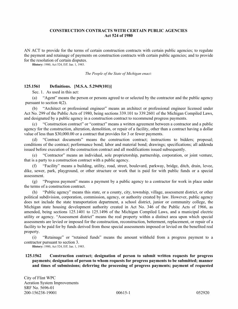
City of Flint WPC
Aeration System Improvements
SRF No. 5696-01
200-156238-19001 00615-1 052920
CONSTRUCTION CONTRACTS WITH CERTAIN PUBLIC AGENCIES
Act 524 of 1980
AN ACT to provide for the terms of certain construction contracts with certain public agencies; to regulate
the payment and retainage of payments on construction contracts with certain public agencies; and to provide
for the resolution of certain disputes. History: 1980, Act 524, Eff. Jan. 1, 1983.
The People of the State of Michigan enact:
125.1561 Definitions. [M.S.A. 5.2949(101)]
Sec. 1. As used in this act:
(a) “Agent” means the person or persons agreed to or selected by the contractor and the public agency
pursuant to section 4(2).
(b) “Architect or professional engineer” means an architect or professional engineer licensed under
Act No. 299 of the Public Acts of 1980, being sections 339.101 to 339.2601 of the Michigan Compiled Laws,
and designated by a public agency in a construction contract to recommend progress payments.
(c) “Construction contract” or “contract” means a written agreement between a contractor and a public
agency for the construction, alteration, demolition, or repair of a facility, other than a contract having a dollar
value of less than $30,000.00 or a contract that provides for 3 or fewer payments.
(d) “Contract documents” means the construction contract; instructions to bidders; proposal;
conditions of the contract; performance bond; labor and material bond; drawings; specifications; all addenda
issued before execution of the construction contract and all modifications issued subsequently.
(e) “Contractor” means an individual, sole proprietorship, partnership, corporation, or joint venture,
that is a party to a construction contract with a public agency.
(f) “Facility” means a building, utility, road, street, boulevard, parkway, bridge, ditch, drain, levee,
dike, sewer, park, playground, or other structure or work that is paid for with public funds or a special
assessment.
(g) “Progress payment” means a payment by a public agency to a contractor for work in place under
the terms of a construction contract.
(h) “Public agency” means this state, or a county, city, township, village, assessment district, or other
political subdivision, corporation, commission, agency, or authority created by law. However, public agency
does not include the state transportation department, a school district, junior or community college, the
Michigan state housing development authority created in Act No. 346 of the Public Acts of 1966, as
amended, being sections 125.1401 to 125.1496 of the Michigan Compiled Laws, and a municipal electric
utility or agency. “Assessment district” means the real property within a distinct area upon which special
assessments are levied or imposed for the construction, reconstruction, betterment, replacement, or repair of a
facility to be paid for by funds derived from those special assessments imposed or levied on the benefited real
property.
(i) “Retainage” or “retained funds” means the amount withheld from a progress payment to a
contractor pursuant to section 3. History: 1980, Act 524, Eff. Jan. 1, 1983.
125.1562 Construction contract; designation of person to submit written requests for progress
payments; designation of person to whom requests for progress payments to be submitted; manner
and times of submissions; deferring the processing of progress payments; payment of requested

City of Flint WPC
Aeration System Improvements
SRF No. 5696-01
200-156238-19001 00615-2 052920
progress payment; failure of public agency to make timely progress payment;
interest. [M.S.A. 5.2949(102)]
Sec. 2. (1) The construction contract shall designate a person representing the contractor who will
submit written requests for progress payments, and a person representing the public agency to whom request
for progress payments are to be submitted. The written requests for progress payments shall be submitted to
the designated person in a manner and at such times as provided in the construction contract.
(2) The processing of progress payments by the public agency may be deferred by the public agency
until work having a prior sequence, as provided in the contract documents, is in place and is approved.
(3) Each progress payment requested, including reasonable interest if requested under subsection (4),
shall be paid within 1 of the following time periods, whichever is later:
(a) Thirty days after the architect or professional engineer has certified to the public agency that work
is in place in the portion of the facility covered by the applicable request for payment in accordance with the
contract documents.
(b) Fifteen days after the public agency has received the funds with which to make the progress
payment from a department or agency of the federal or state government, if any funds are to come from either
of those sources.
(4) Upon failure of a public agency to make a timely progress payment pursuant to this section, the
person designated to submit requests for progress payments may include reasonable interest on amounts past
due in the next request for payment. History: 1980, Act 524, Eff. Jan. 1, 1983.
125.1563 Retaining portion of each progress payment to assure proper performance of
construction contract; retainage; limitations; exceeding pro rata share of public agency's matching
requirement; commingling and deposit of retained funds; releasing to contractor retainage and
interest earned on retainage; irrevocable letter of credit. [M.S.A. 5.2949(103)]
Sec. 3. (1) To assure proper performance of a construction contract by the contractor, a public agency
may retain a portion of each progress payment otherwise due as provided in this section.
(2) The retainage shall be limited to the following:
(a) Not more than 10% of the dollar value of all work in place until work is 50% in place.
(b) After the work in 50% in place, additional retainage shall not be withheld unless the public
agency determines that the contractor is not making satisfactory progress, or for other specific cause relating
to the contractor's performance under the contract. If the public agency so determines, the public agency may
retain not more than 10% of the dollar value of work more than 50% in place.
(3) The retained funds shall not exceed the pro rata share of the public agency's matching requirement
under the construction contract and shall not be commingled with other funds of the public agency and shall
be deposited in an interest bearing account in a regulated financial institution in this state wherein all such
retained funds are kept by the public agency which shall account for both retainage and interest on each
construction contract separately. A public agency is not required to deposit retained funds in an interest
bearing account if the retained funds are to be provided under a state or federal grant and the retained funds
have not been paid to the public agency.
(4) Except as provided in section 4(7) and (8), retainage and interest earned on retainage shall be
released to a contractor together with the final progress payment.
(5) At any time after 94% of work under the contract is in place and at the request of the original
contractor, the public agency shall release the retainage plus interest to the original contractor only if the
original contractor provides to the public agency an irrevocable letter of credit in the amount of the retainage
plus interest, issued by a bank authorized to do business in this state, containing terms mutually acceptable to
the contractor and the public agency. History: 1980, Act 524, Eff. Jan. 1, 1983.

City of Flint WPC
Aeration System Improvements
SRF No. 5696-01
200-156238-19001 00615-3 052920
125.1564 Construction contract; agreement to submit matters described in subsection (3) to
decision of agent; designation of agent; dispute resolution process; use; agent to receive pertinent
information and provide opportunity for informal meeting; decision of agent to be final and
binding; vacation of decision by circuit court; dispute resolution resulting in decision; final
progress payment to original contractor where public agency contracts with subsequent
contractor. [M.S.A. 5.2949(104)]
Sec. 4. (1) The construction contract shall contain an agreement to submit those matters described in
subsection (3) to the decision of an agent at the option of the public agency.
(2) If a dispute regarding a matter described in subsection (3) arises, the contractor and the public
agency shall designate an agent who has background, training, and experience in the construction of facilities
similar to that which is the subject of the contract, as follows:
(a) In an agreement reached within 10 days after a dispute arises.
(b) If an agreement cannot be reached within 10 days after a dispute arises, the public agency shall
designate an agent who has background, training, and experience in the construction of facilities similar to
that which is the subject of the contract and who is not an employee of the agency.
(3) The public agency may request dispute resolution by the agent regarding the following:
(a) At any time during the term of the contract, to determine whether there has been a delay for
reasons that were within the control of the contractor, and the period of time that delay has been caused,
continued, or aggravated by actions of the contractor.
(b) At any time after 94% of work under the contract is in place, whether there has been an
unacceptable delay by the contractor in the performance of the remaining 6% of work under the contract. The
agent shall consider the terms of the contract and the procedures normally followed in the industry and shall
determine whether the delay was for failure to follow reasonable and prudent practices in the industry for
completion of the project.
(4) This dispute resolution process shall be used only for the purpose of determining the rights of the
parties to retained funds and interest earned on retained funds and is not intended to alter, abrogate, or limit
any rights with respect to remedies that are available to enforce or compel performance of the terms of the
contract by either party.
(5) The agent may request and shall receive all pertinent information from the parties and shall
provide an opportunity for an informal meeting to receive comments, documents, and other relevant
information in order to resolve the dispute. The agent shall determine the time, place, and procedure for the
informal meeting. A written decision and reasons for the decision shall be given to the parties within 14 days
after the meeting.
(6) The decision of the agent shall be final and binding upon all parties. Upon application of either
party, the decision of the agent may be vacated by order of the circuit court only upon a finding by the court
that the decision was procured by fraud, duress, or other illegal means.
(7) If the dispute resolution results in a decision:
(a) That there has been a delay as described in subsection (3)(a), all interest earned on retained funds
during the period of delay shall become the property of the public agency.
(b) That there has been unacceptable delay as described in subsection (3)(b), the public agency may
contract with a subsequent contractor to complete the remaining 6% of work under the contract, and interest
earned on retained funds shall become the property of the public agency. A subsequent
contractor under this subdivision shall be paid by the public agency from the following sources until each
source is depleted, in the order listed below:
(i) The dollar value of the original contract, less the dollar value of funds already paid to the original
contractor and the dollar value of work in place for which the original contractor has not received payment.
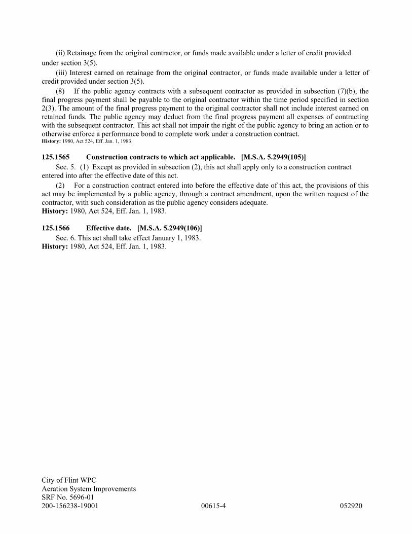
City of Flint WPC
Aeration System Improvements
SRF No. 5696-01
200-156238-19001 00615-4 052920
(ii) Retainage from the original contractor, or funds made available under a letter of credit provided
under section 3(5).
(iii) Interest earned on retainage from the original contractor, or funds made available under a letter of
credit provided under section 3(5).
(8) If the public agency contracts with a subsequent contractor as provided in subsection (7)(b), the
final progress payment shall be payable to the original contractor within the time period specified in section
2(3). The amount of the final progress payment to the original contractor shall not include interest earned on
retained funds. The public agency may deduct from the final progress payment all expenses of contracting
with the subsequent contractor. This act shall not impair the right of the public agency to bring an action or to
otherwise enforce a performance bond to complete work under a construction contract. History: 1980, Act 524, Eff. Jan. 1, 1983.
125.1565 Construction contracts to which act applicable. [M.S.A. 5.2949(105)]
Sec. 5. (1) Except as provided in subsection (2), this act shall apply only to a construction contract
entered into after the effective date of this act.
(2) For a construction contract entered into before the effective date of this act, the provisions of this
act may be implemented by a public agency, through a contract amendment, upon the written request of the
contractor, with such consideration as the public agency considers adequate.
History: 1980, Act 524, Eff. Jan. 1, 1983.
125.1566 Effective date. [M.S.A. 5.2949(106)]
Sec. 6. This act shall take effect January 1, 1983.
History: 1980, Act 524, Eff. Jan. 1, 1983.

City of Flint WPC
Aeration System Improvements
SRF No. 5696-01
200-156238-19001 00620-1 052920
SECTION 00620 - APPLICATION FOR PAYMENT CERTIFICATE
CONTRACTOR’S APPLICATION FOR PAYMENT NO. ___________
CONTRACTOR: TITLE:
OWNER: CONTRACT NO.:
Substantial Completion Date: Final Completion Date:
Milestone Completion Date:
Application is made for payment for the Work shown below, accomplished through the date of
1. Original Contract Sum $
2. Net Change by Change Order $
3. Current Contract Amount (line 1 + line 2) $
4. Work Complete (from summary sheet) % $
5. Stored Materials (from summary sheet, if applicable) $
6. Less % Retainage $
7. Less 10% Retainage - Stored Materials $
8. Total Retainage (line 6 + 7) $
9. Amount Due to Date (line 4 + 5 - 8) $
10. Less Previous Payments (from summary sheet) $
11. Amount Due This Application (line 9-10) $
CONTRACTOR’s Certification:
The undersigned CONTRACTOR certifies that: (1) all previous progress payments received from OWNER on account of
Work done under the Contract referred to above have been applied to discharge in full all obligations of CONTRACTOR
incurred in connection with Work covered by prior Applications for Payment; (2) title to all Work, materials and equipment
incorporated in said Work or otherwise listed in or covered by this Application for Payment will pass to OWNER at time of
payment free and clear of all liens, claims, security interest and encumbrances (except such as are covered by Bond
acceptable to OWNER indemnifying OWNER against any such lien, claim, security interest or encumbrance); and (3) all
Work covered by this Application for Payment is in accordance with the Contract Documents and not defective as that term is
defined in the Contract Documents.
ATTACHMENTS TO THIS CERTIFICATION:
Summary Sheet Change Order Summary Stored Material Summary
Other
CONTRACTOR:
By: Date:
Payment to CONTRACTOR of the amount shown in line 11 above is recommended by ENGINEER,
Tetra Tech, Inc.
By: Date:
APPROVED: OWNER
By: Date:

City of Flint WPC
Aeration System Improvements
SRF No. 5696-01
200-156238-19001 00620-2 052920
Change Order Summary
No. Date Additions Deductions
Subtotals
Total Change In
Contract Price

City of Flint WPC
Aeration System Improvements
SRF No. 5696-01
200-156238-19001 00620-3 052920
Stored Material Summary
Invoice
No.
Stored Material
Material
Location
Insurance
Certificates
on File
Stored Previous Stored This Month Incorporated This
Month
Materials
remaining
in storage
($)
Date
(MO/YR)
Amount
($)
Date
(MO/YR)
Amount
($)
Date
(MO/YR)
Amount
($)
On-Site
Off-Site
Yes / No
On-Site
Off-Site
Yes / No
On-Site
Off-Site
Yes / No

City of Flint WPC
Aeration System Improvements
SRF No. 5696-01
200-156238-19001 00623-1 052920
SECTION 00623 - CERTIFICATES OF INSURANCE
Attach Certificates of Insurance to This Page.

City of Flint WPC
Aeration System Improvements
SRF No. 5696-01
200-156238-19001 00625-1 052920
SECTION 00625 - CERTIFICATE OF COMPONENT ACCEPTANCE
Contract
Contract No.
Date Issued:
Specification Section No.
Equipment Item:
Manufacturer:
Manufacturer’s Representative: Phone:
Address:
The representative named above hereby approves the equipment installation, and certifies that:
1. The equipment has been properly installed and lubricated.
2. The equipment is in accurate alignment.
3. The equipment is free from any undue stress imposed by connecting piping or anchor bolts.
4. The equipment has been operated under full load conditions and that it operated satisfactorily to
ENGINEER.
5. OWNER’s Representative has been instructed in the proper lubrication and operation of the
equipment.
6. OWNER’s Representative has been given a copy of all test data recorded during the installation
check including speed, noise level, vibration, etc. (If no data was taken, so state below.)
The manufacturer's representative takes no exceptions to the above unless such exceptions are written
below: (Continue on another sheet if required.)
Manufacturer’s Representative Date Signature
Witnesses:
Owner’s Representative Date Signature
Contractor’s Representative Date Signature
Engineer’s Representative Date Signature
Owner Date Signature
END OF SECTION

City of Flint WPC
Aeration System Improvements
SRF No. 5696-01
200-156238-19001 00626-1 052920
SECTION 00626 - CERTIFICATE OF SUBSTANTIAL COMPLETION
Contract
Contract No.
Date Issued:
OWNER
CONTRACTOR
This Certificate of Substantial Completion applies to all Work under the Contract Documents or to the following
specified parts thereof:
The Work to which this Certificate applies has been inspected by authorized representatives of OWNER,
CONTRACTOR and ENGINEER, and that Work is hereby declared to be substantially complete in accordance
with the Contract Documents on
____________________________________
DATE OF SUBSTANTIAL COMPLETION
A tentative list of items to be completed or corrected is attached hereto as Attachment No. A. This list may not
be all-inclusive, and the failure to include an item in it does not alter the responsibility of CONTRACTOR to
complete all the Work in accordance with the Contract Documents. The items in the tentative list shall be
completed or corrected by CONTRACTOR within _______ days of the above date of Substantial Completion.
The responsibilities between OWNER and CONTRACTOR for security, operation, safety, maintenance, heat,
utilities, insurance and warranties and guarantees pending final payment shall be as follows:
OWNER: Shall perform and/or maintain insurances, if any, in accordance with Article 5 of the General
Conditions, and allow CONTRACTOR reasonable access to complete or correct items on the tentative
list. Additional responsibilities are:
CONTRACTOR: Shall perform and/or maintain Site security, temporary facilities, Bonds and insurances
in accordance with Article 5 of the General Conditions, and protect the Work. Additional responsibilities
are:

City of Flint WPC
Aeration System Improvements
SRF No. 5696-01
200-156238-19001 00626-2 052920
The following documents are attached to and made a part of this Certificate:
Attachment A: Tentative List of Items to be completed prior to Final Payment (Pages 1 to __, inclusive).
This certificate does not constitute an acceptance of Work not in accordance with the Contract Documents nor is
it a release of CONTRACTOR's obligation to complete the Work in accordance with the Contract Documents.
Executed by ENGINEER on _______________________
Date
___________________________________________
ENGINEER
By: __________________________________________
(Authorized Signature)
CONTRACTOR accepts this Certificate of Substantial Completion on ________________________
Date
__________________________________________
CONTRACTOR
By: __________________________________________
(Authorized Signature)
OWNER accepts this Certificate of Substantial Completion on _______________________
Date
_______________________________________
OWNER
By: _______________________________________
(Authorized Signature)

City of Flint WPC
Aeration System Improvements
SRF No. 5696-01
200-156238-19001 00627-1 052920
SECTION 00627 - CERTIFICATE OF FINAL COMPLETION
Contract
Contract No.
Date Issued:
OWNER
CONTRACTOR
This Certificate of Final Completion applies to all Work under the Contract Documents or to the following
specified parts thereof:
The Work to which this Certificate applies has been inspected by authorized representatives of OWNER,
CONTRACTOR and ENGINEER, in accordance with Paragraph 14.06 of the General Conditions, and that
Work is hereby declared to be finally complete in accordance with the Contract Documents on
____________________________
DATE OF FINAL COMPLETION
CONTRACTOR's general warranty and guarantee period commences on _____________ and terminates on
____________.
CONTRACTOR's special warranty and guarantee are:
___________________ warranty and guarantee period commences on _____________ and terminates on
____________.
___________________ warranty and guarantee period commences on _____________ and terminates on
____________.

City of Flint WPC
Aeration System Improvements
SRF No. 5696-01
200-156238-19001 00627-2 052920
This certificate does not constitute an acceptance of Work not in accordance with the Contract Documents nor is
it a release of CONTRACTOR's obligation to correct defective Work in accordance with the General Conditions
of the Contract Documents.
Executed by ENGINEER on _______________________
Date
___________________________________________
ENGINEER
By: __________________________________________
(Authorized Signature)
CONTRACTOR accepts this Certificate of Final Completion on ________________________
Date
__________________________________________
CONTRACTOR
By: __________________________________________
(Authorized Signature)
OWNER accepts this Certificate of Final Completion on _______________________
Date
_______________________________________
OWNER
By: _______________________________________
(Authorized Signature)

City of Flint WPC
Aeration System Improvements
SRF No. 5696-01
200-156238-19001 00700-1 052920
SECTION 00700 - GENERAL CONDITIONS
ARTICLE 1 - DEFINITIONS AND TERMINOLOGY
_______________________________________________
1.01 Defined Terms
A. Wherever used in the Contract Documents and
printed with initial or all capital letters, the terms listed
below will have the meanings indicated which are
applicable to both the singular and plural thereof.
1. Addenda--Written or graphic instruments
issued prior to the opening of Bids which clarify, correct, or
change the Bidding Requirements or the Contract
Documents.
2. Agreement--The written instrument which is
evidence of the agreement between OWNER and
CONTRACTOR covering the Work.
3. Application for Payment--The form
acceptable to ENGINEER which is to be used by
CONTRACTOR during the course of the Work in
requesting progress or final payments and which is to be
accompanied by such supporting documentation as is
required by the Contract Documents.
4. Asbestos--Any material that contains more
than one percent asbestos and is friable or is releasing
asbestos fibers into the air above current action levels
established by the United States Occupational Safety and
Health Administration.
5. Bid--The offer or proposal of a bidder
submitted on the prescribed form setting forth the prices for
the Work to be performed.
6. Bidding Documents--The Bidding
Requirements and the proposed Contract Documents
(including all Addenda issued prior to receipt of Bids).
7. Bidding Requirements--The Advertisement or
Invitation to Bid, Instructions to Bidders, Bid security
form, if any, and the Bid form with any supplements.
8. Bonds--Performance and payment bonds and
other instruments of security.
9. Change Order--A document recommended
by ENGINEER which is signed by CONTRACTOR and
OWNER and authorizes an addition, deletion, or revision
in the Work or an adjustment in the Contract Price or the
Contract Times, issued on or after the Effective Date of the
Agreement.
10. Claim--A demand or assertion by OWNER or
CONTRACTOR seeking an adjustment of Contract Price
or Contract Times, or both, or other relief with respect to
the terms of the Contract. A demand for money or services
by a third party is not a Claim.
11. Contract--The entire and integrated written
agreement between the OWNER and CONTRACTOR
concerning the Work. The Contract supersedes prior
negotiations, representations, or agreements, whether
written or oral.
12. Contract Documents--The Contract
Documents establish the rights and obligations of the
parties and include the Agreement, Addenda (which pertain
to the Contract Documents), CONTRACTOR’s Bid
(including documentation accompanying the Bid and any
post Bid documentation submitted prior to the Notice of
Award) when attached as an exhibit to the Agreement, the
Notice to Proceed, the Bonds, these General Conditions,
the Supplementary Conditions, the Specifications and the
Drawings as the same are more specifically identified in the
Agreement, together with all Written Amendments, Change
Orders, Work Change Directives, Field Orders, and
ENGINEER’s written interpretations and clarifications
issued on or after the Effective Date of the Agreement.
Approved Shop Drawings and the reports and drawings of
subsurface and physical conditions are not Contract
Documents. Only printed or hard copies of the items listed
in this paragraph are Contract Documents. Files in
electronic media format of text, data, graphics, and the like
that may be furnished by OWNER to CONTRACTOR are
not Contract Documents.
13. Contract Price--The moneys payable by
OWNER to CONTRACTOR for completion of the Work
in accordance with the Contract Documents as stated in the
Agreement (subject to the provisions of Paragraph 11.03 in
the case of Unit Price Work).
14. Contract Times--The number of days or the
dates stated in the Agreement to: (i) achieve Substantial
Completion; and (ii) complete the Work so that it is ready
for final payment as evidenced by ENGINEER’s written
recommendation of final payment.
15. CONTRACTOR--The individual or entity
with whom OWNER has entered into the Agreement.
16. Cost of the Work--See Paragraph 11.01.A for
definition.
17. Drawings--That part of the Contract
Documents prepared or approved by ENGINEER which

City of Flint WPC
Aeration System Improvements
SRF No. 5696-01
200-156238-19001 00700-2 052920
graphically shows the scope, extent, and character of the
Work to be performed by CONTRACTOR. Shop Drawings
and other CONTRACTOR submittals are not Drawings as
so defined.
18. Effective Date of the Agreement--The date
indicated in the Agreement on which it becomes effective,
but if no such date is indicated, it means the date on which
the Agreement is signed and delivered by the last of the
two parties to sign and deliver.
19. ENGINEER--The individual or entity named
as such in the Agreement.
20. ENGINEER's Consultant--An individual or
entity having a contract with ENGINEER to furnish
services as ENGINEER’s independent professional
associate or consultant with respect to the Project and who
is identified as such in the Supplementary Conditions.
21. Field Order--A written order issued by
ENGINEER which requires minor changes in the Work but
which does not involve a change in the Contract Price or
the Contract Times.
22. General Requirements--Sections of Division
1 of the Specifications. The General Requirements pertain
to all sections of the Specifications.
23. Hazardous Environmental Condition--The
presence at the Site of Asbestos, PCBs, Petroleum,
Hazardous Waste, or Radioactive Material in such
quantities or circumstances that may present a substantial
danger to persons or property exposed thereto in
connection with the Work.
24. Hazardous Waste--The term Hazardous
Waste shall have the meaning provided in Section 1004 of
the Solid Waste Disposal Act (42 USC Section 6903) as
amended from time to time.
25. Laws and Regulations; Laws or Regulations--
Any and all applicable laws, rules, regulations, ordinances,
codes, and orders of any and all governmental bodies,
agencies, authorities, and courts having jurisdiction.
26. Liens--Charges, security interests, or
encumbrances upon Project funds, real property, or
personal property.
27. Milestone--A principal event specified in the
Contract Documents relating to an intermediate completion
date or time prior to Substantial Completion of all the
Work.
28. Notice of Award--The written notice by
OWNER to the apparent successful bidder stating that upon
timely compliance by the apparent successful bidder with
the conditions precedent listed therein, OWNER will sign
and deliver the Agreement.
29. Notice to Proceed--A written notice given by
OWNER to CONTRACTOR fixing the date on which the
Contract Times will commence to run and on which
CONTRACTOR shall start to perform the Work under the
Contract Documents.
30. OWNER--The individual, entity, public body,
or authority with whom CONTRACTOR has entered into
the Agreement and for whom the Work is to be performed.
31. Partial Utilization--Use by OWNER of a
substantially completed part of the Work for the purpose
for which it is intended (or a related purpose) prior to
Substantial Completion of all the Work.
32. PCBs--Polychlorinated biphenyls.
33. Petroleum--Petroleum, including crude oil or
any fraction thereof which is liquid at standard conditions
of temperature and pressure (60 degrees Fahrenheit and
14.7 pounds per square inch absolute), such as oil,
petroleum, fuel oil, oil sludge, oil refuse, gasoline,
kerosene, and oil mixed with other non-Hazardous Waste
and crude oils.
34. Project--The total construction of which the
Work to be performed under the Contract Documents may
be the whole, or a part as may be indicated elsewhere in the
Contract Documents.
35. Project Manual--The bound documentary
information prepared for bidding and constructing the
Work. A listing of the contents of the Project Manual,
which may be bound in one or more volumes, is contained
in the table(s) of contents.
36. Radioactive Material--Source, special
nuclear, or byproduct material as defined by the Atomic
Energy Act of 1954 (42 USC Section 2011 et seq.) as
amended from time to time.
37. Resident Project Representative--The
authorized representative of ENGINEER who may be
assigned to the Site or any part thereof.
38. Samples--Physical examples of materials,
equipment, or workmanship that are representative of some
portion of the Work and which establish the standards by
which such portion of the Work will be judged.

City of Flint WPC
Aeration System Improvements
SRF No. 5696-01
200-156238-19001 00700-3 052920
39. Shop Drawings--All drawings, diagrams,
illustrations, schedules, and other data or information
which are specifically prepared or assembled by or for
CONTRACTOR and submitted by CONTRACTOR to
illustrate some portion of the Work.
40. Site--Lands or areas indicated in the Contract
Documents as being furnished by OWNER upon which the
Work is to be performed, including rights-of-way and
easements for access thereto, and such other lands
furnished by OWNER which are designated for the use of
CONTRACTOR.
41. Specifications--That part of the Contract
Documents consisting of written technical descriptions of
materials, equipment, systems, standards, and workmanship
as applied to the Work and certain administrative details
applicable thereto.
42. Subcontractor--An individual or entity
having a direct contract with CONTRACTOR or with any
other Subcontractor for the performance of a part of the
Work at the Site.
43. Substantial Completion--The time at which
the Work (or a specified part thereof) has progressed to the
point where, in the opinion of ENGINEER, the Work (or a
specified part thereof) is sufficiently complete, in
accordance with the Contract Documents, so that the Work
(or a specified part thereof) can be utilized for the purposes
for which it is intended. The terms “substantially complete”
and “substantially completed” as applied to all or part of
the Work refer to Substantial Completion thereof.
44. Supplementary Conditions--That part of the
Contract Documents which amends or supplements these
General Conditions.
45. Supplier--A manufacturer, fabricator,
supplier, distributor, materialman, or vendor having a direct
contract with CONTRACTOR or with any Subcontractor
to furnish materials or equipment to be incorporated in the
Work by CONTRACTOR or any Subcontractor.
46. Underground Facilities--All underground
pipelines, conduits, ducts, cables, wires, manholes, vaults,
tanks, tunnels, or other such facilities or attachments, and
any encasements containing such facilities, including those
that convey electricity, gases, steam, liquid petroleum
products, telephone or other communications, cable
television, water, wastewater, storm water, other liquids or
chemicals, or traffic or other control systems.
47. Unit Price Work--Work to be paid for on the
basis of unit prices.
48. Work--The entire completed construction or
the various separately identifiable parts thereof required to
be provided under the Contract Documents. Work includes
and is the result of performing or providing all labor,
services, and documentation necessary to produce such
construction, and furnishing, installing, and incorporating
all materials and equipment into such construction, all as
required by the Contract Documents.
49. Work Change Directive--A written statement
to CONTRACTOR issued on or after the Effective Date of
the Agreement and signed by OWNER and recommended
by ENGINEER ordering an addition, deletion, or revision
in the Work, or responding to differing or unforeseen
subsurface or physical conditions under which the Work is
to be performed or to emergencies. A Work Change
Directive will not change the Contract Price or the Contract
Times but is evidence that the parties expect that the
change ordered or documented by a Work Change
Directive will be incorporated in a subsequently issued
Change Order following negotiations by the parties as to its
effect, if any, on the Contract Price or Contract Times.
50. Written Amendment--A written statement
modifying the Contract Documents, signed by OWNER
and CONTRACTOR on or after the Effective Date of the
Agreement and normally dealing with the nonengineering
or nontechnical rather than strictly construction-related
aspects of the Contract Documents.
1.02 Terminology
A. Intent of Certain Terms or Adjectives
1. Whenever in the Contract Documents the
terms “as allowed,” “as approved,” or terms of like
effect or import are used, or the adjectives
“reasonable,” “suitable,” “acceptable,” “proper,”
“satisfactory,” or adjectives of like effect or import are
used to describe an action or determination of
ENGINEER as to the Work, it is intended that such
action or determination will be solely to evaluate, in
general, the completed Work for compliance with the
requirements of and information in the Contract
Documents and conformance with the design concept
of the completed Project as a functioning whole as
shown or indicated in the Contract Documents (unless
there is a specific statement indicating otherwise). The
use of any such term or adjective shall not be effective
to assign to ENGINEER any duty or authority to
supervise or direct the performance of the Work or any
duty or authority to undertake responsibility contrary to

City of Flint WPC
Aeration System Improvements
SRF No. 5696-01
200-156238-19001 00700-4 052920
the provisions of Paragraph 9.10 or any other provision
of the Contract Documents.
B. Day
1. The word “day” shall constitute a
calendar day of 24 hours measured from midnight
to the next midnight.
C. Defective
1. The word “defective,” when modifying
the word “Work,” refers to Work that is
unsatisfactory, faulty, or deficient in that it does not
conform to the Contract Documents or does not
meet the requirements of any inspection, reference
standard, test, or approval referred to in the Contract
Documents, or has been damaged prior to
ENGINEER’s recommendation of final payment
(unless responsibility for the protection thereof has
been assumed by OWNER at Substantial
Completion in accordance with Paragraph 14.04 or
14.05).
D. Furnish, Install, Perform, Provide
1. The word “furnish,” when used in
connection with services, materials, or equipment,
shall mean to supply and deliver said services,
materials, or equipment to the Site (or some other
specified location) ready for use or installation and
in usable or operable condition.
2. The word “install,” when used in
connection with services, materials, or equipment,
shall mean to put into use or place in final position
said services, materials, or equipment complete and
ready for intended use.
3. The words “perform” or “provide,” when
used in connection with services, materials, or
equipment, shall mean to furnish and install said
services, materials, or equipment complete and
ready for intended use.
4. When “furnish,” “install,” “perform,” or
“provide” is not used in connection with services,
materials, or equipment in a context clearly requiring an
obligation of CONTRACTOR, “provide” is implied.
E. Unless stated otherwise in the Contract
Documents, words or phrases which have a well-known
technical or construction industry or trade meaning are used
in the Contract Documents in accordance with such
recognized meaning.
ARTICLE 2 - PRELIMINARY MATTERS
_______________________________________________
2.01 Delivery of Bonds
A. When CONTRACTOR delivers the executed
Agreements to OWNER, CONTRACTOR shall also
deliver to OWNER such Bonds as CONTRACTOR may
be required to furnish.
2.02 Copies of Documents
A. OWNER shall furnish to CONTRACTOR up to
ten copies of the Contract Documents. Additional copies
will be furnished upon request at the cost of reproduction.
2.03 Commencement of Contract Times; Notice to
Proceed
A. The Contract Times will commence to run on the
thirtieth day after the Effective Date of the Agreement or, if
a Notice to Proceed is given, on the day indicated in the
Notice to Proceed. A Notice to Proceed may be given at
any time within 30 days after the Effective Date of the
Agreement. In no event will the Contract Times commence
to run later than the sixtieth day after the day of Bid
opening or the thirtieth day after the Effective Date of the
Agreement, whichever date is earlier.
2.04 Starting the Work
A. CONTRACTOR shall start to perform the Work
on the date when the Contract Times commence to run. No
Work shall be done at the Site prior to the date on which
the Contract Times commence to run.
2.05 Before Starting Construction
A. CONTRACTOR’s Review of Contract Documents:
Before undertaking each part of the Work,
CONTRACTOR shall carefully study and compare the
Contract Documents and check and verify pertinent figures
therein and all applicable field measurements.
CONTRACTOR shall promptly report in writing to
ENGINEER any conflict, error, ambiguity, or discrepancy
which CONTRACTOR may discover and shall obtain a
written interpretation or clarification from ENGINEER
before proceeding with any Work affected thereby;
however, CONTRACTOR shall not be liable to OWNER
or ENGINEER for failure to report any conflict, error,
ambiguity, or discrepancy in the Contract Documents
unless CONTRACTOR knew or reasonably should have
known thereof.

City of Flint WPC
Aeration System Improvements
SRF No. 5696-01
200-156238-19001 00700-5 052920
B. Preliminary Schedules: Within ten days after the
Effective Date of the Agreement (unless otherwise
specified in the General Requirements), CONTRACTOR
shall submit to ENGINEER for its timely review:
1. a preliminary progress schedule
indicating the times (numbers of days or dates) for
starting and completing the various stages of the
Work, including any Milestones specified in the
Contract Documents;
2. a preliminary schedule of Shop Drawing
and Sample submittals which will list each required
submittal and the times for submitting, reviewing,
and processing such submittal; and
3. a preliminary schedule of values for all
of the Work which includes quantities and prices of
items which when added together equal the
Contract Price and subdivides the Work into
component parts in sufficient detail to serve as the
basis for progress payments during performance of
the Work. Such prices will include an appropriate
amount of overhead and profit applicable to each
item of Work.
C. Evidence of Insurance: Before any Work at the
Site is started, CONTRACTOR and OWNER shall each
deliver to the other, with copies to each additional insured
identified in the Supplementary Conditions, certificates of
insurance (and other evidence of insurance which either of
them or any additional insured may reasonably request)
which CONTRACTOR and OWNER respectively are
required to purchase and maintain in accordance with
Article 5.
2.06 Preconstruction Conference
A. Within 20 days after the Contract Times start to
run, but before any Work at the Site is started, a conference
attended by CONTRACTOR, ENGINEER, and others as
appropriate will be held to establish a working
understanding among the parties as to the Work and to
discuss the schedules referred to in Paragraph 2.05.B,
procedures for handling Shop Drawings and other
submittals, processing Applications for Payment, and
maintaining required records.
2.07 Initial Acceptance of Schedules
A. Unless otherwise provided in the Contract
Documents, at least ten days before submission of the first
Application for Payment a conference attended by
CONTRACTOR, ENGINEER, and others as appropriate
will be held to review for acceptability to ENGINEER as
provided below the schedules submitted in accordance with
Paragraph 2.05.B. CONTRACTOR shall have an
additional ten days to make corrections and adjustments
and to complete and resubmit the schedules. No progress
payment shall be made to CONTRACTOR until acceptable
schedules are submitted to ENGINEER.
1. The progress schedule will be acceptable
to ENGINEER if it provides an orderly progression
of the Work to completion within any specified
Milestones and the Contract Times. Such
acceptance will not impose on ENGINEER
responsibility for the progress schedule, for
sequencing, scheduling, or progress of the Work nor
interfere with or relieve CONTRACTOR from
CONTRACTOR’s full responsibility therefor.
2. CONTRACTOR’s schedule of Shop
Drawing and Sample submittals will be acceptable
to ENGINEER if it provides a workable
arrangement for reviewing and processing the
required submittals.
3. CONTRACTOR’s schedule of values
will be acceptable to ENGINEER as to form and
substance if it provides a reasonable allocation of
the Contract Price to component parts of the Work.
ARTICLE 3 - CONTRACT DOCUMENTS: INTENT,
AMENDING, REUSE
_______________________________________________
3.01 Intent
A. The Contract Documents are complementary;
what is called for by one is as binding as if called for by all.
B. It is the intent of the Contract Documents to
describe a functionally complete Project (or part thereof) to
be constructed in accordance with the Contract Documents.
Any labor, documentation, services, materials, or
equipment that may reasonably be inferred from the
Contract Documents or from prevailing custom or trade
usage as being required to produce the intended result will
be provided whether or not specifically called for at no
additional cost to OWNER.
C. Clarifications and interpretations of the Contract
Documents shall be issued by ENGINEER as provided in
Article 9.
City of Flint WPC
Aeration System Improvements
SRF No. 5696-01
200-156238-19001 00700-6 052920
3.02 Reference Standards
A. Standards, Specifications, Codes, Laws, and
Regulations
1. Reference to standards, specifications,
manuals, or codes of any technical society,
organization, or association, or to Laws or
Regulations, whether such reference be specific or
by implication, shall mean the standard,
specification, manual, code, or Laws or Regulations
in effect at the time of opening of Bids (or on the
Effective Date of the Agreement if there were no
Bids), except as may be otherwise specifically
stated in the Contract Documents.
2. No provision of any such standard,
specification, manual or code, or any instruction of
a Supplier shall be effective to change the duties or
responsibilities of OWNER, CONTRACTOR, or
ENGINEER, or any of their subcontractors,
consultants, agents, or employees from those set
forth in the Contract Documents, nor shall any such
provision or instruction be effective to assign to
OWNER, ENGINEER, or any of ENGINEER’s
Consultants, agents, or employees any duty or
authority to supervise or direct the performance of
the Work or any duty or authority to undertake
responsibility inconsistent with the provisions of the
Contract Documents.
3.03 Reporting and Resolving Discrepancies
A. Reporting Discrepancies
1. If, during the performance of the Work,
CONTRACTOR discovers any conflict, error,
ambiguity, or discrepancy within the Contract
Documents or between the Contract Documents and
any provision of any Law or Regulation applicable
to the performance of the Work or of any standard,
specification, manual or code, or of any instruction
of any Supplier, CONTRACTOR shall report it to
ENGINEER in writing at once. CONTRACTOR
shall not proceed with the Work affected thereby
(except in an emergency as required by Paragraph
6.16.A) until an amendment or supplement to the
Contract Documents has been issued by one of the
methods indicated in Paragraph 3.04; provided,
however, that CONTRACTOR shall not be liable to
OWNER or ENGINEER for failure to report any
such conflict, error, ambiguity, or discrepancy
unless CONTRACTOR knew or reasonably should
have known thereof.
B. Resolving Discrepancies
1. Except as may be otherwise specifically
stated in the Contract Documents, the provisions of
the Contract Documents shall take precedence in
resolving any conflict, error, ambiguity, or
discrepancy between the provisions of the Contract
Documents and:
a. the provisions of any standard,
specification, manual, code, or instruction
(whether or not specifically incorporated by
reference in the Contract Documents); or
b. the provisions of any Laws or
Regulations applicable to the performance of the
Work (unless such an interpretation of the
provisions of the Contract Documents would
result in violation of such Law or Regulation).
3.04 Amending and Supplementing Contract
Documents
A. The Contract Documents may be amended to
provide for additions, deletions, and revisions in the Work
or to modify the terms and conditions thereof in one or
more of the following ways: (i) a Written Amendment; (ii)
a Change Order; or (iii) a Work Change Directive.
B. The requirements of the Contract Documents may
be supplemented, and minor variations and deviations in
the Work may be authorized, by one or more of the
following ways: (i) a Field Order; (ii) ENGINEER’s
approval of a Shop Drawing or Sample; or (iii)
ENGINEER’s written interpretation or clarification.
3.05 Reuse of Documents
A. CONTRACTOR and any Subcontractor or
Supplier or other individual or entity performing or
furnishing any of the Work under a direct or indirect
contract with OWNER: (i) shall not have or acquire any
title to or ownership rights in any of the Drawings,
Specifications, or other documents (or copies of any
thereof) prepared by or bearing the seal of ENGINEER or
ENGINEER’s Consultant, including electronic media
editions; and (ii) shall not reuse any of such Drawings,
Specifications, other documents, or copies thereof on
extensions of the Project or any other project without
written consent of OWNER and ENGINEER and specific
written verification or adaption by ENGINEER. This
prohibition will survive final payment, completion, and
acceptance of the Work, or termination or completion of
the Contract. Nothing herein shall preclude

City of Flint WPC
Aeration System Improvements
SRF No. 5696-01
200-156238-19001 00700-7 052920
CONTRACTOR from retaining copies of the Contract
Documents for record purposes.
ARTICLE 4 - AVAILABILITY OF LANDS;
SUBSURFACE AND PHYSICAL CONDITIONS;
REFERENCE POINTS
_______________________________________________
4.01 Availability of Lands
A. OWNER shall furnish the Site. OWNER shall
notify CONTRACTOR of any encumbrances or
restrictions not of general application but specifically
related to use of the Site with which CONTRACTOR must
comply in performing the Work. OWNER will obtain in a
timely manner and pay for easements for permanent
structures or permanent changes in existing facilities. If
CONTRACTOR and OWNER are unable to agree on
entitlement to or on the amount or extent, if any, of any
adjustment in the Contract Price or Contract Times, or
both, as a result of any delay in OWNER’s furnishing the
Site, CONTRACTOR may make a Claim therefor as
provided in Paragraph 10.05.
B. Upon reasonable written request, OWNER shall
furnish CONTRACTOR with a current statement of record
legal title and legal description of the lands upon which the
Work is to be performed and OWNER’s interest therein as
necessary for giving notice of or filing a mechanic's or
construction lien against such lands in accordance with
applicable Laws and Regulations.
C. CONTRACTOR shall provide for all additional
lands and access thereto that may be required for temporary
construction facilities or storage of materials and
equipment.
4.02 Subsurface and Physical Conditions
A. Reports and Drawings: The Supplementary
Conditions identify:
1. those reports of explorations and tests of
subsurface conditions at or contiguous to the Site
that ENGINEER has used in preparing the Contract
Documents; and
2. those drawings of physical conditions in
or relating to existing surface or subsurface
structures at or contiguous to the Site (except
Underground Facilities) that ENGINEER has used
in preparing the Contract Documents.
B. Limited Reliance by CONTRACTOR on Technical
Data Authorized: CONTRACTOR may rely upon the
general accuracy of the “technical data” contained in such
reports and drawings, but such reports and drawings are not
Contract Documents. Such “technical data” is identified in
the Supplementary Conditions. Except for such reliance on
such “technical data,” CONTRACTOR may not rely upon
or make any Claim against OWNER, ENGINEER, or any
of ENGINEER’s Consultants with respect to:
1. the completeness of such reports and
drawings for CONTRACTOR’s purposes,
including, but not limited to, any aspects of the
means, methods, techniques, sequences, and
procedures of construction to be employed by
CONTRACTOR, and safety precautions and
programs incident thereto; or
2. other data, interpretations, opinions, and
information contained in such reports or shown or
indicated in such drawings; or
3. any CONTRACTOR interpretation of or
conclusion drawn from any "technical data" or any
such other data, interpretations, opinions, or
information.
4.03 Differing Subsurface or Physical Conditions
A. Notice: If CONTRACTOR believes that any
subsurface or physical condition at or contiguous to the Site
that is uncovered or revealed either:
1. is of such a nature as to establish that any
“technical data” on which CONTRACTOR is
entitled to rely as provided in Paragraph 4.02 is
materially inaccurate; or
2. is of such a nature as to require a change
in the Contract Documents; or
3. differs materially from that shown or
indicated in the Contract Documents; or
4. is of an unusual nature, and differs
materially from conditions ordinarily encountered
and generally recognized as inherent in work of the
character provided for in the Contract Documents;
then CONTRACTOR shall, promptly after becoming
aware thereof and before further disturbing the subsurface
or physical conditions or performing any Work in
connection therewith (except in an emergency as required
by Paragraph 6.16.A), notify OWNER and ENGINEER in
writing about such condition. CONTRACTOR shall not
City of Flint WPC
Aeration System Improvements
SRF No. 5696-01
200-156238-19001 00700-8 052920
further disturb such condition or perform any Work in
connection therewith (except as aforesaid) until receipt of
written order to do so.
B. ENGINEER’s Review: After receipt of written
notice as required by Paragraph 4.03.A, ENGINEER will
promptly review the pertinent condition, determine the
necessity of OWNER's obtaining additional exploration or
tests with respect thereto, and advise OWNER in writing
(with a copy to CONTRACTOR) of ENGINEER’s
findings and conclusions.
C. Possible Price and Times Adjustments
1. The Contract Price or the Contract
Times, or both, will be equitably adjusted to the
extent that the existence of such differing
subsurface or physical condition causes an increase
or decrease in CONTRACTOR’s cost of, or time
required for, performance of the Work; subject,
however, to the following:
a. such condition must meet any one or
more of the categories described in Paragraph
4.03.A; and
b. with respect to Work that is paid for on a
Unit Price Basis, any adjustment in Contract
Price will be subject to the provisions of
Paragraphs 9.08 and 11.03.
2. CONTRACTOR shall not be entitled to
any adjustment in the Contract Price or Contract
Times if:
a. CONTRACTOR knew of the existence
of such conditions at the time CONTRACTOR
made a final commitment to OWNER in respect
of Contract Price and Contract Times by the
submission of a Bid or becoming bound under a
negotiated contract; or
b. the existence of such condition could
reasonably have been discovered or revealed as
a result of any examination, investigation,
exploration, test, or study of the Site and
contiguous areas required by the Bidding
Requirements or Contract Documents to be
conducted by or for CONTRACTOR prior to
CONTRACTOR's making such final
commitment; or
c. CONTRACTOR failed to give the
written notice within the time and as required by
Paragraph 4.03.A.
3. If OWNER and CONTRACTOR are
unable to agree on entitlement to or on the amount
or extent, if any, of any adjustment in the Contract
Price or Contract Times, or both, a Claim may be
made therefor as provided in Paragraph 10.05.
However, OWNER, ENGINEER, and
ENGINEER’s Consultants shall not be liable to
CONTRACTOR for any claims, costs, losses, or
damages (including but not limited to all fees and
charges of engineers, architects, attorneys, and other
professionals and all court or arbitration or other
dispute resolution costs) sustained by
CONTRACTOR on or in connection with any other
project or anticipated project.
4.04 Underground Facilities
A. Shown or Indicated: The information and data
shown or indicated in the Contract Documents with respect
to existing Underground Facilities at or contiguous to the
Site is based on information and data furnished to OWNER
or ENGINEER by the owners of such Underground
Facilities, including OWNER, or by others. Unless it is
otherwise expressly provided in the Supplementary
Conditions:
1. OWNER and ENGINEER shall not be
responsible for the accuracy or completeness of any
such information or data; and
2. the cost of all of the following will be
included in the Contract Price, and CONTRACTOR
shall have full responsibility for:
a. reviewing and checking all such
information and data,
b. locating all Underground Facilities
shown or indicated in the Contract Documents,
c. coordination of the Work with the
owners of such Underground Facilities,
including OWNER, during construction, and
d. the safety and protection of all such
Underground Facilities and repairing any
damage thereto resulting from the Work.
B. Not Shown or Indicated
1. If an Underground Facility is uncovered
or revealed at or contiguous to the Site which was
not shown or indicated, or not shown or indicated
with reasonable accuracy in the Contract

City of Flint WPC
Aeration System Improvements
SRF No. 5696-01
200-156238-19001 00700-9 052920
Documents, CONTRACTOR shall, promptly after
becoming aware thereof and before further
disturbing conditions affected thereby or performing
any Work in connection therewith (except in an
emergency as required by Paragraph 6.16.A),
identify the owner of such Underground Facility
and give written notice to that owner and to
OWNER and ENGINEER. ENGINEER will
promptly review the Underground Facility and
determine the extent, if any, to which a change is
required in the Contract Documents to reflect and
document the consequences of the existence or
location of the Underground Facility. During such
time, CONTRACTOR shall be responsible for the
safety and protection of such Underground Facility.
2. If ENGINEER concludes that a change
in the Contract Documents is required, a Work
Change Directive or a Change Order will be issued
to reflect and document such consequences. An
equitable adjustment shall be made in the Contract
Price of Contract Times, or both, to the extent that
they are attributable to the existence or location of
any Underground Facility that was not shown or
indicated or not shown or indicated with reasonable
accuracy in the Contract Documents and that
CONTRACTOR did not know of and could not
reasonably have been expected to be aware of or to
have anticipated. If OWNER and CONTRACTOR
are unable to agree on entitlement to or on the
amount or extent, if any, of any such adjustment in
Contract Price or Contract Times, OWNER or
CONTRACTOR may make a Claim therefor as
provided in Paragraph 10.05.
4.05 Reference Points
A. OWNER shall provide engineering surveys to
establish reference points for construction which in
ENGINEER’s judgment are necessary to enable
CONTRACTOR to proceed with the Work.
CONTRACTOR shall be responsible for laying out the
Work, shall protect and preserve the established reference
points and property monuments, and shall make no changes
or relocations without the prior written approval of
OWNER. CONTRACTOR shall report to ENGINEER
whenever any reference point or property monument is lost
or destroyed or requires relocation because of necessary
changes in grades or locations, and shall be responsible for
the accurate replacement or relocation of such reference
points or property monuments by professionally qualified
personnel.
4.06 Hazardous Environmental Condition at Site
A. Reports and Drawings: Reference is made to the
Supplementary Conditions for the identification of those
reports and drawings relating to a Hazardous
Environmental Condition identified at the Site, if any, that
have been utilized by the ENGINEER in the preparation of
the Contract Documents.
B. Limited Reliance by CONTRACTOR on Technical
Data Authorized: CONTRACTOR may rely upon the
general accuracy of the “technical data” contained in such
reports and drawings, but such reports and drawings are not
Contract Documents. Such “technical data” is identified in
the Supplementary Conditions. Except for such reliance on
such “technical data,” CONTRACTOR may not rely upon
or make any Claim against OWNER, ENGINEER or any
of ENGINEER’s Consultants with respect to:
1. the completeness of such reports and
drawings for CONTRACTOR’s purposes,
including, but not limited to, any aspects of the
means, methods, techniques, sequences and
procedures of construction to be employed by
CONTRACTOR and safety precautions and
programs incident thereto; or
2. other data, interpretations, opinions and
information contained in such reports or shown or
indicated in such drawings; or
3. any CONTRACTOR interpretation of or
conclusion drawn from any “technical data” or any
such other data, interpretations, opinions or
information.
C. CONTRACTOR shall not be responsible for any
Hazardous Environmental Condition uncovered or revealed
at the Site which was not shown or indicated in Drawings
or Specifications or identified in the Contract Documents to
be within the scope of the Work. CONTRACTOR shall be
responsible for a Hazardous Environmental Condition
created with any materials brought to the Site by
CONTRACTOR, Subcontractors, Suppliers, or anyone else
for whom CONTRACTOR is responsible.
D. If CONTRACTOR encounters a Hazardous
Environmental Condition or if CONTRACTOR or anyone
for whom CONTRACTOR is responsible creates a
Hazardous Environmental Condition, CONTRACTOR
shall immediately: (i) secure or otherwise isolate such
condition; (ii) stop all Work in connection with such
condition and in any area affected thereby (except in an
emergency as required by Paragraph 6.16); and (iii) notify
OWNER and ENGINEER (and promptly thereafter
City of Flint WPC
Aeration System Improvements
SRF No. 5696-01
200-156238-19001 00700-10 052920
confirm such notice in writing). OWNER shall promptly
consult with ENGINEER concerning the necessity for
OWNER to retain a qualified expert to evaluate such
condition or take corrective action, if any.
E. CONTRACTOR shall not be required to resume
Work in connection with such condition or in any affected
area until after OWNER has obtained any required permits
related thereto and delivered to CONTRACTOR written
notice: (i) specifying that such condition and any affected
area is or has been rendered safe for the resumption of
Work; or (ii) specifying any special conditions under which
such Work may be resumed safely. If OWNER and
CONTRACTOR cannot agree as to entitlement to or on the
amount or extent, if any, of any adjustment in Contract
Price or Contract Times, or both, as a result of such Work
stoppage or such special conditions under which Work is
agreed to be resumed by CONTRACTOR, either party may
make a Claim therefor as provided in Paragraph 10.05.
F. If after receipt of such written notice
CONTRACTOR does not agree to resume such Work
based on a reasonable belief it is unsafe, or does not agree
to resume such Work under such special conditions, then
OWNER may order the portion of the Work that is in the
area affected by such condition to be deleted from the
Work. If OWNER and CONTRACTOR cannot agree as to
entitlement to or on the amount or extent, if any, of an
adjustment in Contract Price or Contract Times as a result
of deleting such portion of the Work, then either party may
make a Claim therefor as provided in Paragraph 10.05.
OWNER may have such deleted portion of the Work
performed by OWNER’s own forces or others in
accordance with Article 7.
G. To the fullest extent permitted by Laws and
Regulations, OWNER shall indemnify and hold harmless
CONTRACTOR, Subcontractors, ENGINEER,
ENGINEER’s Consultants and the officers, directors,
partners, employees, agents, other consultants, and
subcontractors of each and any of them from and against all
claims, costs, losses, and damages (including but not
limited to all fees and charges of engineers, architects,
attorneys, and other professionals and all court or
arbitration or other dispute resolution costs) arising out of
or relating to a Hazardous Environmental Condition,
provided that such Hazardous Environmental Condition:
(i) was not shown or indicated in the Drawings or
Specifications or identified in the Contract Documents to
be included within the scope of the Work, and (ii) was not
created by CONTRACTOR or by anyone for whom
CONTRACTOR is responsible. Nothing in this Paragraph
4.06.E shall obligate OWNER to indemnify any individual
or entity from and against the consequences of that
individual’s or entity’s own negligence.
H. To the fullest extent permitted by Laws and
Regulations, CONTRACTOR shall indemnify and hold
harmless OWNER, ENGINEER, ENGINEER’s
Consultants, and the officers, directors, partners,
employees, agents, other consultants, and subcontractors of
each and any of them from and against all claims, costs,
losses, and damages (including but not limited to all fees
and charges of engineers, architects, attorneys, and other
professionals and all court or arbitration or other dispute
resolution costs) arising out of or relating to a Hazardous
Environmental Condition created by CONTRACTOR or
by anyone for whom CONTRACTOR is responsible.
Nothing in this Paragraph 4.06.F shall obligate
CONTRACTOR to indemnify any individual or entity
from and against the consequences of that individual’s or
entity’s own negligence.
I. The provisions of Paragraphs 4.02, 4.03, and 4.04
are not intended to apply to a Hazardous Environmental
Condition uncovered or revealed at the Site.
ARTICLE 5 - BONDS AND INSURANCE
_______________________________________________
5.01 Performance, Payment, and Other Bonds
A. CONTRACTOR shall furnish performance and
payment Bonds, each in an amount at least equal to the
Contract Price as security for the faithful performance and
payment of all CONTRACTOR’s obligations under the
Contract Documents. These Bonds shall remain in effect at
least until one year after the date when final payment
becomes due, except as provided otherwise by Laws or
Regulations or by the Contract Documents.
CONTRACTOR shall also furnish such other Bonds as are
required by the Contract Documents.
B. All Bonds shall be in the form prescribed by the
Contract Documents except as provided otherwise by Laws
or Regulations, and shall be executed by such sureties as
are named in the current list of “Companies Holding
Certificates of Authority as Acceptable Sureties on Federal
Bonds and as Acceptable Reinsuring Companies” as
published in Circular 570 (amended) by the Financial
Management Service, Surety Bond Branch, U.S.
Department of the Treasury. All Bonds signed by an agent
must be accompanied by a certified copy of such agent’s
authority to act.
C. If the surety on any Bond furnished by
CONTRACTOR is declared bankrupt or becomes insolvent
or its right to do business is terminated in any state where
any part of the Project is located or it ceases to meet the

City of Flint WPC
Aeration System Improvements
SRF No. 5696-01
200-156238-19001 00700-11 052920
requirements of Paragraph 5.01.B, CONTRACTOR shall
within 20 days thereafter substitute another Bond and
surety, both of which shall comply with the requirements of
Paragraphs 5.01.B and 5.02.
5.02 Licensed Sureties and Insurers
A. All Bonds and insurance required by the Contract
Documents to be purchased and maintained by OWNER or
CONTRACTOR shall be obtained from surety or insurance
companies that are duly licensed or authorized in the
jurisdiction in which the Project is located to issue Bonds
or insurance policies for the limits and coverages so
required. Such surety and insurance companies shall also
meet such additional requirements and qualifications as
may be provided in the Supplementary Conditions.
5.03 Certificates of Insurance
A. CONTRACTOR shall deliver to OWNER, with
copies to each additional insured identified in the
Supplementary Conditions, certificates of insurance (and
other evidence of insurance requested by OWNER or any
other additional insured) which CONTRACTOR is
required to purchase and maintain. OWNER shall deliver to
CONTRACTOR, with copies to each additional insured
identified in the Supplementary Conditions, certificates of
insurance (and other evidence of insurance requested by
CONTRACTOR or any other additional insured) which
OWNER is required to purchase and maintain.
5.04 CONTRACTOR’s Liability Insurance
A. CONTRACTOR shall purchase and maintain
such liability and other insurance as is appropriate for the
Work being performed and as will provide protection from
claims set forth below which may arise out of or result
from CONTRACTOR’s performance of the Work and
CONTRACTOR’s other obligations under the Contract
Documents, whether it is to be performed by
CONTRACTOR, any Subcontractor or Supplier, or by
anyone directly or indirectly employed by any of them to
perform any of the Work, or by anyone for whose acts any
of them may be liable:
1. claims under workers’ compensation,
disability benefits, and other similar employee
benefit acts;
2. claims for damages because of bodily
injury, occupational sickness or disease, or death of
CONTRACTOR’s employees;
3. claims for damages because of bodily
injury, sickness or disease, or death of any person
other than CONTRACTOR’s employees;
4. claims for damages insured by
reasonably available personal injury liability
coverage which are sustained: (i) by any person as a
result of an offense directly or indirectly related to
the employment of such person by
CONTRACTOR, or (ii) by any other person for any
other reason;
5. claims for damages, other than to the
Work itself, because of injury to or destruction of
tangible property wherever located, including loss
of use resulting therefrom; and
6. claims for damages because of bodily
injury or death of any person or property damage
arising out of the ownership, maintenance or use of
any motor vehicle.
B. The policies of insurance so required by this
Paragraph 5.04 to be purchased and maintained shall:
1. with respect to insurance required by
Paragraphs 5.04.A.3 through 5.04.A.6 inclusive,
include as additional insureds (subject to any
customary exclusion in respect of professional
liability) OWNER, ENGINEER, ENGINEER's
Consultants, and any other individuals or entities
identified in the Supplementary Conditions, all of
whom shall be listed as additional insureds, and
include coverage for the respective officers,
directors, partners, employees, agents, and other
consultants and subcontractors of each and any of
all such additional insureds, and the insurance
afforded to these additional insureds shall provide
primary coverage for all claims covered thereby;
2. include at least the specific coverages
and be written for not less than the limits of liability
provided in the Supplementary Conditions or
required by Laws or Regulations, whichever is
greater;
3. include completed operations insurance;
4. include contractual liability insurance
covering CONTRACTOR’s indemnity obligations
under Paragraphs 6.07, 6.11, and 6.20;
5. contain a provision or endorsement that
the coverage afforded will not be canceled,
materially changed or renewal refused until at least

City of Flint WPC
Aeration System Improvements
SRF No. 5696-01
200-156238-19001 00700-12 052920
thirty days prior written notice has been given to
OWNER and CONTRACTOR and to each other
additional insured identified in the Supplementary
Conditions to whom a certificate of insurance has
been issued (and the certificates of insurance
furnished by the CONTRACTOR pursuant to
Paragraph 5.03 will so provide);
6. remain in effect at least until final
payment and at all times thereafter when
CONTRACTOR may be correcting, removing, or
replacing defective Work in accordance with
Paragraph 13.07; and
7. with respect to completed operations
insurance, and any insurance coverage written on a
claims-made basis, remain in effect for at least two
years after final payment (and CONTRACTOR
shall furnish OWNER and each other additional
insured identified in the Supplementary Conditions,
to whom a certificate of insurance has been issued,
evidence satisfactory to OWNER and any such
additional insured of continuation of such insurance
at final payment and one year thereafter).
5.05 OWNER’s Liability Insurance
A. In addition to the insurance required to be
provided by CONTRACTOR under Paragraph 5.04,
OWNER, at OWNER’s option, may purchase and maintain
at OWNER’s expense OWNER’s own liability insurance
as will protect OWNER against claims which may arise
from operations under the Contract Documents.
5.06 Property Insurance
A. Unless otherwise provided in the Supplementary
Conditions, OWNER shall purchase and maintain property
insurance upon the Work at the Site in the amount of the
full replacement cost thereof (subject to such deductible
amounts as may be provided in the Supplementary
Conditions or required by Laws and Regulations). This
insurance shall:
1. include the interests of OWNER,
CONTRACTOR, Subcontractors, ENGINEER,
ENGINEER’s Consultants, and any other
individuals or entities identified in the
Supplementary Conditions, and the officers,
directors, partners, employees, agents, and other
consultants and subcontractors of each and any of
them, each of whom is deemed to have an insurable
interest and shall be listed as an additional insured;
2. be written on a Builder’s Risk “all-risk”
or open peril or special causes of loss policy form
that shall at least include insurance for physical loss
or damage to the Work, temporary buildings, false
work, and materials and equipment in transit, and
shall insure against at least the following perils or
causes of loss: fire, lightning, extended coverage,
theft, vandalism and malicious mischief,
earthquake, collapse, debris removal, demolition
occasioned by enforcement of Laws and
Regulations, water damage, and such other perils or
causes of loss as may be specifically required by the
Supplementary Conditions;
3. include expenses incurred in the repair or
replacement of any insured property (including but
not limited to fees and charges of engineers and
architects);
4. cover materials and equipment stored at
the Site or at another location that was agreed to in
writing by OWNER prior to being incorporated in
the Work, provided that such materials and
equipment have been included in an Application for
Payment recommended by ENGINEER;
5. allow for partial utilization of the Work
by OWNER;
6. include testing and startup; and
7. be maintained in effect until final
payment is made unless otherwise agreed to in
writing by OWNER, CONTRACTOR, and
ENGINEER with 30 days written notice to each
other additional insured to whom a certificate of
insurance has been issued.
B. OWNER shall purchase and maintain such boiler
and machinery insurance or additional property insurance
as may be required by the Supplementary Conditions or
Laws and Regulations which will include the interests of
OWNER, CONTRACTOR, Subcontractors, ENGINEER,
ENGINEER’s Consultants, and any other individuals or
entities identified in the Supplementary Conditions, each of
whom is deemed to have an insurable interest and shall be
listed as an insured or additional insured.
C. All the policies of insurance (and the certificates
or other evidence thereof) required to be purchased and
maintained in accordance with Paragraph 5.06 will contain
a provision or endorsement that the coverage afforded will
not be canceled or materially changed or renewal refused
until at least 30 days prior written notice has been given to
OWNER and CONTRACTOR and to each other additional
City of Flint WPC
Aeration System Improvements
SRF No. 5696-01
200-156238-19001 00700-13 052920
insured to whom a certificate of insurance has been issued
and will contain waiver provisions in accordance with
Paragraph 5.07.
D. OWNER shall not be responsible for purchasing
and maintaining any property insurance specified in this
Paragraph 5.06 to protect the interests of CONTRACTOR,
Subcontractors, or others in the Work to the extent of any
deductible amounts that are identified in the Supplementary
Conditions. The risk of loss within such identified
deductible amount will be borne by CONTRACTOR,
Subcontractors, or others suffering any such loss, and if any
of them wishes property insurance coverage within the
limits of such amounts, each may purchase and maintain it
at the purchaser’s own expense.
E. If CONTRACTOR requests in writing that other
special insurance be included in the property insurance
policies provided under Paragraph 5.06, OWNER shall, if
possible, include such insurance, and the cost thereof will
be charged to CONTRACTOR by appropriate Change
Order or Written Amendment. Prior to commencement of
the Work at the Site, OWNER shall in writing advise
CONTRACTOR whether or not such other insurance has
been procured by OWNER.
5.07 Waiver of Rights
A. OWNER and CONTRACTOR intend that all
policies purchased in accordance with Paragraph 5.06 will
protect OWNER, CONTRACTOR, Subcontractors,
ENGINEER, ENGINEER’s Consultants, and all other
individuals or entities identified in the Supplementary
Conditions to be listed as insureds or additional insureds
(and the officers, directors, partners, employees, agents,
and other consultants and subcontractors of each and any of
them) in such policies and will provide primary coverage
for all losses and damages caused by the perils or causes of
loss covered thereby. All such policies shall contain
provisions to the effect that in the event of payment of any
loss or damage the insurers will have no rights of recovery
against any of the insureds or additional insureds
thereunder. OWNER and CONTRACTOR waive all rights
against each other and their respective officers, directors,
partners, employees, agents, and other consultants and
subcontractors of each and any of them for all losses and
damages caused by, arising out of or resulting from any of
the perils or causes of loss covered by such policies and
any other property insurance applicable to the Work; and,
in addition, waive all such rights against Subcontractors,
ENGINEER, ENGINEER’s Consultants, and all other
individuals or entities identified in the Supplementary
Conditions to be listed as insureds or additional insureds
(and the officers, directors, partners, employees, agents,
and other consultants and subcontractors of each and any of
them) under such policies for losses and damages so
caused. None of the above waivers shall extend to the
rights that any party making such waiver may have to the
proceeds of insurance held by OWNER as trustee or
otherwise payable under any policy so issued.
B. OWNER waives all rights against
CONTRACTOR, Subcontractors, ENGINEER,
ENGINEER’s Consultants, and the officers, directors,
partners, employees, agents, and other consultants and
subcontractors of each and any of them for:
1. loss due to business interruption, loss of
use, or other consequential loss extending beyond
direct physical loss or damage to OWNER’s
property or the Work caused by, arising out of, or
resulting from fire or other peril whether or not
insured by OWNER; and
2. loss or damage to the completed Project
or part thereof caused by, arising out of, or resulting
from fire or other insured peril or cause of loss
covered by any property insurance maintained on
the completed Project or part thereof by OWNER
during partial utilization pursuant to Paragraph
14.05, after Substantial Completion pursuant to
Paragraph 14.04, or after final payment pursuant to
Paragraph 14.07.
C. Any insurance policy maintained by OWNER
covering any loss, damage or consequential loss referred to
in Paragraph 5.07.B shall contain provisions to the effect
that in the event of payment of any such loss, damage, or
consequential loss, the insurers will have no rights of
recovery against CONTRACTOR, Subcontractors,
ENGINEER, or ENGINEER’s Consultants and the
officers, directors, partners, employees, agents, and other
consultants and subcontractors of each and any of them.
5.08 Receipt and Application of Insurance Proceeds
A. Any insured loss under the policies of insurance
required by Paragraph 5.06 will be adjusted with OWNER
and made payable to OWNER as fiduciary for the insureds,
as their interests may appear, subject to the requirements of
any applicable mortgage clause and of Paragraph 5.08.B.
OWNER shall deposit in a separate account any money so
received and shall distribute it in accordance with such
agreement as the parties in interest may reach. If no other
special agreement is reached, the damaged Work shall be
repaired or replaced, the moneys so received applied on
account thereof, and the Work and the cost thereof covered
by an appropriate Change Order or Written Amendment.

City of Flint WPC
Aeration System Improvements
SRF No. 5696-01
200-156238-19001 00700-14 052920
B. OWNER as fiduciary shall have power to adjust
and settle any loss with the insurers unless one of the
parties in interest shall object in writing within 15 days
after the occurrence of loss to OWNER’s exercise of this
power. If such objection be made, OWNER as fiduciary
shall make settlement with the insurers in accordance with
such agreement as the parties in interest may reach. If no
such agreement among the parties in interest is reached,
OWNER as fiduciary shall adjust and settle the loss with
the insurers and, if required in writing by any party in
interest, OWNER as fiduciary shall give bond for the
proper performance of such duties.
5.09 Acceptance of Bonds and Insurance; Option to
Replace
A. If either OWNER or CONTRACTOR has any
objection to the coverage afforded by or other provisions of
the Bonds or insurance required to be purchased and
maintained by the other party in accordance with Article 5
on the basis of nonconformance with the Contract
Documents, the objecting party shall so notify the other
party in writing within 10 days after receipt of the
certificates (or other evidence requested) required by
Paragraph 2.05.C. OWNER and CONTRACTOR shall
each provide to the other such additional information in
respect of insurance provided as the other may reasonably
request. If either party does not purchase or maintain all of
the Bonds and insurance required of such party by the
Contract Documents, such party shall notify the other party
in writing of such failure to purchase prior to the start of the
Work, or of such failure to maintain prior to any change in
the required coverage. Without prejudice to any other right
or remedy, the other party may elect to obtain equivalent
Bonds or insurance to protect such other party's interests at
the expense of the party who was required to provide such
coverage, and a Change Order shall be issued to adjust the
Contract Price accordingly.
5.10 Partial Utilization, Acknowledgment of Property
Insurer
A. If OWNER finds it necessary to occupy or use a
portion or portions of the Work prior to Substantial
Completion of all the Work as provided in Paragraph
14.05, no such use or occupancy shall commence before
the insurers providing the property insurance pursuant to
Paragraph 5.06 have acknowledged notice thereof and in
writing effected any changes in coverage necessitated
thereby. The insurers providing the property insurance shall
consent by endorsement on the policy or policies, but the
property insurance shall not be canceled or permitted to
lapse on account of any such partial use or occupancy.
ARTICLE 6 - CONTRACTOR’S RESPONSIBILITIES
_______________________________________________
6.01 Supervision and Superintendence
A. CONTRACTOR shall supervise, inspect, and
direct the Work competently and efficiently, devoting such
attention thereto and applying such skills and expertise as
may be necessary to perform the Work in accordance with
the Contract Documents. CONTRACTOR shall be solely
responsible for the means, methods, techniques, sequences,
and procedures of construction, but CONTRACTOR shall
not be responsible for the negligence of OWNER or
ENGINEER in the design or specification of a specific
means, method, technique, sequence, or procedure of
construction which is shown or indicated in and expressly
required by the Contract Documents. CONTRACTOR
shall be responsible to see that the completed Work
complies accurately with the Contract Documents.
B. At all times during the progress of the Work,
CONTRACTOR shall assign a competent resident
superintendent thereto who shall not be replaced without
written notice to OWNER and ENGINEER except under
extraordinary circumstances. The superintendent will be
CONTRACTOR’s representative at the Site and shall have
authority to act on behalf of CONTRACTOR. All
communications given to or received from the
superintendent shall be binding on CONTRACTOR.
6.02 Labor; Working Hours
A. CONTRACTOR shall provide competent,
suitably qualified personnel to survey, lay out, and
construct the Work as required by the Contract Documents.
CONTRACTOR shall at all times maintain good discipline
and order at the Site.
B. Except as otherwise required for the safety or
protection of persons or the Work or property at the Site or
adjacent thereto, and except as otherwise stated in the
Contract Documents, all Work at the Site shall be
performed during regular working hours, and
CONTRACTOR will not permit overtime work or the
performance of Work on Saturday, Sunday, or any legal
holiday without OWNER’s written consent (which will not
be unreasonably withheld) given after prior written notice
to ENGINEER.
6.03 Services, Materials, and Equipment
A. Unless otherwise specified in the General
Requirements, CONTRACTOR shall provide and assume
full responsibility for all services, materials, equipment,
labor, transportation, construction equipment and

City of Flint WPC
Aeration System Improvements
SRF No. 5696-01
200-156238-19001 00700-15 052920
machinery, tools, appliances, fuel, power, light, heat,
telephone, water, sanitary facilities, temporary facilities,
and all other facilities and incidentals necessary for the
performance, testing, start-up, and completion of the Work.
B. All materials and equipment incorporated into the
Work shall be as specified or, if not specified, shall be of
good quality and new, except as otherwise provided in the
Contract Documents. All warranties and guarantees
specifically called for by the Specifications shall expressly
run to the benefit of OWNER. If required by ENGINEER,
CONTRACTOR shall furnish satisfactory evidence
(including reports of required tests) as to the source, kind,
and quality of materials and equipment. All materials and
equipment shall be stored, applied, installed, connected,
erected, protected, used, cleaned, and conditioned in
accordance with instructions of the applicable Supplier,
except as otherwise may be provided in the Contract
Documents.
6.04 Progress Schedule
A. CONTRACTOR shall adhere to the progress
schedule established in accordance with Paragraph 2.07 as
it may be adjusted from time to time as provided below.
1. CONTRACTOR shall submit to
ENGINEER for acceptance (to the extent indicated
in Paragraph 2.07) proposed adjustments in the
progress schedule that will not result in changing
the Contract Times (or Milestones). Such
adjustments will conform generally to the progress
schedule then in effect and additionally will comply
with any provisions of the General Requirements
applicable thereto.
2. Proposed adjustments in the progress
schedule that will change the Contract Times (or
Milestones) shall be submitted in accordance with
the requirements of Article 12. Such adjustments
may only be made by a Change Order or Written
Amendment in accordance with Article 12.
6.05 Substitutes and “Or-Equals
A. Whenever an item of material or equipment is
specified or described in the Contract Documents by using
the name of a proprietary item or the name of a particular
Supplier, the specification or description is intended to
establish the type, function, appearance, and quality
required. Unless the specification or description contains or
is followed by words reading that no like, equivalent, or
“or-equal” item or no substitution is permitted, other items
of material or equipment or material or equipment of other
Suppliers may be submitted to ENGINEER for review
under the circumstances described below.
1. “Or-Equal” Items: If in ENGINEER’s
sole discretion an item of material or equipment
proposed by CONTRACTOR is functionally equal
to that named and sufficiently similar so that no
change in related Work will be required, it may be
considered by ENGINEER as an “or-equal” item, in
which case review and approval of the proposed
item may, in ENGINEER’s sole discretion, be
accomplished without compliance with some or all
of the requirements for approval of proposed
substitute items. For the purposes of this Paragraph
6.05.A.1, a proposed item of material or equipment
will be considered functionally equal to an item so
named if:
a. in the exercise of reasonable judgment
ENGINEER determines that: (i) it is at least
equal in quality, durability, appearance, strength,
and design characteristics; (ii) it will reliably
perform at least equally well the function
imposed by the design concept of the completed
Project as a functioning whole, and;
b. CONTRACTOR certifies that: (i) there
is no increase in cost to the OWNER; and (ii) it
will conform substantially, even with deviations,
to the detailed requirements of the item named
in the Contract Documents.
2. Substitute Items
a. If in ENGINEER’s sole discretion an
item of material or equipment proposed by
CONTRACTOR does not qualify as an
“or-equal” item under Paragraph 6.05.A.1, it
will be considered a proposed substitute item.
b. CONTRACTOR shall submit sufficient
information as provided below to allow
ENGINEER to determine that the item of
material or equipment proposed is essentially
equivalent to that named and an acceptable
substitute therefor. Requests for review of
proposed substitute items of material or
equipment will not be accepted by ENGINEER
from anyone other than CONTRACTOR.
c. The procedure for review by
ENGINEER will be as set forth in Paragraph
6.05.A.2.d, as supplemented in the General
Requirements and as ENGINEER may decide is
appropriate under the circumstances.

City of Flint WPC
Aeration System Improvements
SRF No. 5696-01
200-156238-19001 00700-16 052920
d. CONTRACTOR shall first make written
application to ENGINEER for review of a
proposed substitute item of material or
equipment that CONTRACTOR seeks to
furnish or use. The application shall certify that
the proposed substitute item will perform
adequately the functions and achieve the results
called for by the general design, be similar in
substance to that specified, and be suited to the
same use as that specified. The application will
state the extent, if any, to which the use of the
proposed substitute item will prejudice
CONTRACTOR’s achievement of Substantial
Completion on time, whether or not use of the
proposed substitute item in the Work will
require a change in any of the Contract
Documents (or in the provisions of any other
direct contract with OWNER for work on the
Project) to adapt the design to the proposed
substitute item and whether or not incorporation
or use of the proposed substitute item in
connection with the Work is subject to payment
of any license fee or royalty. All variations of
the proposed substitute item from that specified
will be identified in the application, and
available engineering, sales, maintenance,
repair, and replacement services will be
indicated. The application will also contain an
itemized estimate of all costs or credits that will
result directly or indirectly from use of such
substitute item, including costs of redesign and
claims of other contractors affected by any
resulting change, all of which will be considered
by ENGINEER in evaluating the proposed
substitute item. ENGINEER may require
CONTRACTOR to furnish additional data
about the proposed substitute item.
B. Substitute Construction Methods or Procedures:
If a specific means, method, technique, sequence, or
procedure of construction is shown or indicated in and
expressly required by the Contract Documents,
CONTRACTOR may furnish or utilize a substitute means,
method, technique, sequence, or procedure of construction
approved by ENGINEER. CONTRACTOR shall submit
sufficient information to allow ENGINEER, in
ENGINEER’s sole discretion, to determine that the
substitute proposed is equivalent to that expressly called for
by the Contract Documents. The procedure for review by
ENGINEER will be similar to that provided in
Subparagraph 6.05.A.2.
C. Engineer’s Evaluation: ENGINEER will be
allowed a reasonable time within which to evaluate each
proposal or submittal made pursuant to Paragraphs 6.05.A
and 6.05.B. ENGINEER will be the sole judge of
acceptability. No “or-equal” or substitute will be ordered,
installed or utilized until ENGINEER’s review is complete,
which will be evidenced by either a Change Order for a
substitute or an approved Shop Drawing for an “or equal.”
ENGINEER will advise CONTRACTOR in writing of any
negative determination.
D. Special Guarantee: OWNER may require
CONTRACTOR to furnish at CONTRACTOR’s expense a
special performance guarantee or other surety with respect
to any substitute.
E. ENGINEER’s Cost Reimbursement: ENGINEER
will record time required by ENGINEER and
ENGINEER’s Consultants in evaluating substitute
proposed or submitted by CONTRACTOR pursuant to
Paragraphs 6.05.A.2 and 6.05.B and in making changes in
the Contract Documents (or in the provisions of any other
direct contract with OWNER for work on the Project)
occasioned thereby. Whether or not ENGINEER approves
a substitute item so proposed or submitted by
CONTRACTOR, CONTRACTOR shall reimburse
OWNER for the charges of ENGINEER and ENGINEER’s
Consultants for evaluating each such proposed substitute.
F. CONTRACTOR’s Expense: CONTRACTOR
shall provide all data in support of any proposed substitute
or “or-equal” at CONTRACTOR’s expense.
6.06 Concerning Subcontractors, Suppliers, and
Others
A. CONTRACTOR shall not employ any
Subcontractor, Supplier, or other individual or entity
(including those acceptable to OWNER as indicated in
Paragraph 6.06.B), whether initially or as a replacement,
against whom OWNER may have reasonable objection.
CONTRACTOR shall not be required to employ any
Subcontractor, Supplier, or other individual or entity to
furnish or perform any of the Work against whom
CONTRACTOR has reasonable objection.
B. If the Supplementary Conditions require the
identity of certain Subcontractors, Suppliers, or other
individuals or entities to be submitted to OWNER in
advance for acceptance by OWNER by a specified date
prior to the Effective Date of the Agreement, and if
CONTRACTOR has submitted a list thereof in accordance
with the Supplementary Conditions, OWNER’s acceptance
(either in writing or by failing to make written objection
thereto by the date indicated for acceptance or objection in
the Bidding Documents or the Contract Documents) of any
such Subcontractor, Supplier, or other individual or entity

City of Flint WPC
Aeration System Improvements
SRF No. 5696-01
200-156238-19001 00700-17 052920
so identified may be revoked on the basis of reasonable
objection after due investigation. CONTRACTOR shall
submit an acceptable replacement for the rejected
Subcontractor, Supplier, or other individual or entity, and
the Contract Price will be adjusted by the difference in the
cost occasioned by such replacement, and an appropriate
Change Order will be issued or Written Amendment
signed. No acceptance by OWNER of any such
Subcontractor, Supplier, or other individual or entity,
whether initially or as a replacement, shall constitute a
waiver of any right of OWNER or ENGINEER to reject
defective Work.
C. CONTRACTOR shall be fully responsible to
OWNER and ENGINEER for all acts and omissions of the
Subcontractors, Suppliers, and other individuals or entities
performing or furnishing any of the Work just as
CONTRACTOR is responsible for CONTRACTOR’s own
acts and omissions. Nothing in the Contract Documents
shall create for the benefit of any such Subcontractor,
Supplier, or other individual or entity any contractual
relationship between OWNER or ENGINEER and any
such Subcontractor, Supplier or other individual or entity,
nor shall it create any obligation on the part of OWNER or
ENGINEER to pay or to see to the payment of any moneys
due any such Subcontractor, Supplier, or other individual or
entity except as may otherwise be required by Laws and
Regulations.
D. CONTRACTOR shall be solely responsible for
scheduling and coordinating the Work of Subcontractors,
Suppliers, and other individuals or entities performing or
furnishing any of the Work under a direct or indirect
contract with CONTRACTOR.
E. CONTRACTOR shall require all Subcontractors,
Suppliers, and such other individuals or entities performing
or furnishing any of the Work to communicate with
ENGINEER through CONTRACTOR.
F. The divisions and sections of the Specifications
and the identifications of any Drawings shall not control
CONTRACTOR in dividing the Work among
Subcontractors or Suppliers or delineating the Work to be
performed by any specific trade.
G. All Work performed for CONTRACTOR by a
Subcontractor or Supplier will be pursuant to an
appropriate agreement between CONTRACTOR and the
Subcontractor or Supplier which specifically binds the
Subcontractor or Supplier to the applicable terms and
conditions of the Contract Documents for the benefit of
OWNER and ENGINEER. Whenever any such agreement
is with a Subcontractor or Supplier who is listed as an
additional insured on the property insurance provided in
Paragraph 5.06, the agreement between the
CONTRACTOR and the Subcontractor or Supplier will
contain provisions whereby the Subcontractor or Supplier
waives all rights against OWNER, CONTRACTOR,
ENGINEER, ENGINEER’s Consultants, and all other
individuals or entities identified in the Supplementary
Conditions to be listed as insureds or additional insureds
(and the officers, directors, partners, employees, agents,
and other consultants and subcontractors of each and any of
them) for all losses and damages caused by, arising out of,
relating to, or resulting from any of the perils or causes of
loss covered by such policies and any other property
insurance applicable to the Work. If the insurers on any
such policies require separate waiver forms to be signed by
any Subcontractor or Supplier, CONTRACTOR will obtain
the same.
6.07 Patent Fees and Royalties
A. CONTRACTOR shall pay all license fees and
royalties and assume all costs incident to the use in the
performance of the Work or the incorporation in the Work
of any invention, design, process, product, or device which
is the subject of patent rights or copyrights held by others.
If a particular invention, design, process, product, or device
is specified in the Contract Documents for use in the
performance of the Work and if to the actual knowledge of
OWNER or ENGINEER its use is subject to patent rights
or copyrights calling for the payment of any license fee or
royalty to others, the existence of such rights shall be
disclosed by OWNER in the Contract Documents. To the
fullest extent permitted by Laws and Regulations,
CONTRACTOR shall indemnify and hold harmless
OWNER, ENGINEER, ENGINEER’s Consultants, and the
officers, directors, partners, employees or agents, and other
consultants of each and any of them from and against all
claims, costs, losses, and damages (including but not
limited to all fees and charges of engineers, architects,
attorneys, and other professionals and all court or
arbitration or other dispute resolution costs) arising out of
or relating to any infringement of patent rights or
copyrights incident to the use in the performance of the
Work or resulting from the incorporation in the Work of
any invention, design, process, product, or device not
specified in the Contract Documents.
6.08 Permits
A. Unless otherwise provided in the Supplementary
Conditions, CONTRACTOR shall obtain and pay for all
construction permits and licenses. OWNER shall assist
CONTRACTOR, when necessary, in obtaining such
permits and licenses. CONTRACTOR shall pay all
governmental charges and inspection fees necessary for the
prosecution of the Work which are applicable at the time of

City of Flint WPC
Aeration System Improvements
SRF No. 5696-01
200-156238-19001 00700-18 052920
opening of Bids, or, if there are no Bids, on the Effective
Date of the Agreement. CONTRACTOR shall pay all
charges of utility owners for connections to the Work, and
OWNER shall pay all charges of such utility owners for
capital costs related thereto, such as plant investment fees.
6.09 Laws and Regulations
A. CONTRACTOR shall give all notices and comply
with all Laws and Regulations applicable to the
performance of the Work. Except where otherwise
expressly required by applicable Laws and Regulations,
neither OWNER nor ENGINEER shall be responsible for
monitoring CONTRACTOR’s compliance with any Laws
or Regulations.
B. If CONTRACTOR performs any Work knowing
or having reason to know that it is contrary to Laws or
Regulations, CONTRACTOR shall bear all claims, costs,
losses, and damages (including but not limited to all fees
and charges of engineers, architects, attorneys, and other
professionals and all court or arbitration or other dispute
resolution costs) arising out of or relating to such Work;
however, it shall not be CONTRACTOR’s primary
responsibility to make certain that the Specifications and
Drawings are in accordance with Laws and Regulations,
but this shall not relieve CONTRACTOR of
CONTRACTOR’s obligations under Paragraph 3.03.
C. Changes in Laws or Regulations not known at the
time of opening of Bids (or, on the Effective Date of the
Agreement if there were no Bids) having an effect on the
cost or time of performance of the Work may be the subject
of an adjustment in Contract Price or Contract Times. If
OWNER and CONTRACTOR are unable to agree on
entitlement to or on the amount or extent, if any, of any
such adjustment, a Claim may be made therefor as
provided in Paragraph 10.05.
6.10 Taxes
A. CONTRACTOR shall pay all sales, consumer,
use, and other similar taxes required to be paid by
CONTRACTOR in accordance with the Laws and
Regulations of the place of the Project which are applicable
during the performance of the Work.
6.11 Use of Site and Other Areas
A. Limitation on Use of Site and Other Areas
1. CONTRACTOR shall confine
construction equipment, the storage of materials and
equipment, and the operations of workers to the Site
and other areas permitted by Laws and Regulations,
and shall not unreasonably encumber the Site and
other areas with construction equipment or other
materials or equipment. CONTRACTOR shall
assume full responsibility for any damage to any
such land or area, or to the owner or occupant
thereof, or of any adjacent land or areas resulting
from the performance of the Work.
2. Should any claim be made by any such
owner or occupant because of the performance of
the Work, CONTRACTOR shall promptly settle
with such other party by negotiation or otherwise
resolve the claim by arbitration or other dispute
resolution proceeding or at law.
3. To the fullest extent permitted by Laws
and Regulations, CONTRACTOR shall indemnify
and hold harmless OWNER, ENGINEER,
ENGINEER’s Consultant, and the officers,
directors, partners, employees, agents, and other
consultants of each and any of them from and
against all claims, costs, losses, and damages
(including but not limited to all fees and charges of
engineers, architects, attorneys, and other
professionals and all court or arbitration or other
dispute resolution costs) arising out of or relating to
any claim or action, legal or equitable, brought by
any such owner or occupant against OWNER,
ENGINEER, or any other party indemnified
hereunder to the extent caused by or based upon
CONTRACTOR's performance of the Work.
B. Removal of Debris During Performance of the
Work: During the progress of the Work CONTRACTOR
shall keep the Site and other areas free from accumulations
of waste materials, rubbish, and other debris. Removal and
disposal of such waste materials, rubbish, and other debris
shall conform to applicable Laws and Regulations.
C. Cleaning: Prior to Substantial Completion of the
Work CONTRACTOR shall clean the Site and make it
ready for utilization by OWNER. At the completion of the
Work CONTRACTOR shall remove from the Site all tools,
appliances, construction equipment and machinery, and
surplus materials and shall restore to original condition all
property not designated for alteration by the Contract
Documents.
D. Loading Structures: CONTRACTOR shall not
load nor permit any part of any structure to be loaded in
any manner that will endanger the structure, nor shall
CONTRACTOR subject any part of the Work or adjacent
property to stresses or pressures that will endanger it.
City of Flint WPC
Aeration System Improvements
SRF No. 5696-01
200-156238-19001 00700-19 052920
6.12 Record Documents
A. CONTRACTOR shall maintain in a safe place at
the Site one record copy of all Drawings, Specifications,
Addenda, Written Amendments, Change Orders, Work
Change Directives, Field Orders, and written interpretations
and clarifications in good order and annotated to show
changes made during construction. These record
documents together with all approved Samples and a
counterpart of all approved Shop Drawings will be
available to ENGINEER for reference. Upon completion of
the Work, these record documents, Samples, and Shop
Drawings will be delivered to ENGINEER for OWNER.
6.13 Safety and Protection
A. CONTRACTOR shall be solely responsible for
initiating, maintaining and supervising all safety
precautions and programs in connection with the Work.
CONTRACTOR shall take all necessary precautions for
the safety of, and shall provide the necessary protection to
prevent damage, injury or loss to:
1. all persons on the Site or who may be
affected by the Work;
2. all the Work and materials and
equipment to be incorporated therein, whether in
storage on or off the Site; and
3. other property at the Site or adjacent
thereto, including trees, shrubs, lawns, walks,
pavements, roadways, structures, utilities, and
Underground Facilities not designated for removal,
relocation, or replacement in the course of
construction.
B. CONTRACTOR shall comply with all applicable
Laws and Regulations relating to the safety of persons or
property, or to the protection of persons or property from
damage, injury, or loss; and shall erect and maintain all
necessary safeguards for such safety and protection.
CONTRACTOR shall notify owners of adjacent property
and of Underground Facilities and other utility owners
when prosecution of the Work may affect them, and shall
cooperate with them in the protection, removal, relocation,
and replacement of their property. All damage, injury, or
loss to any property referred to in paragraph 6.13.A.2 or
6.13.A.3 caused, directly or indirectly, in whole or in part,
by CONTRACTOR, any Subcontractor, Supplier, or any
other individual or entity directly or indirectly employed by
any of them to perform any of the Work, or anyone for
whose acts any of them may be liable, shall be remedied by
CONTRACTOR (except damage or loss attributable to the
fault of Drawings or Specifications or to the acts or
omissions of OWNER or ENGINEER or ENGINEER’s
Consultant, or anyone employed by any of them, or anyone
for whose acts any of them may be liable, and not
attributable, directly or indirectly, in whole or in part, to the
fault or negligence of CONTRACTOR or any
Subcontractor, Supplier, or other individual or entity
directly or indirectly employed by any of them).
CONTRACTOR’s duties and responsibilities for safety and
for protection of the Work shall continue until such time as
all the Work is completed and ENGINEER has issued a
notice to OWNER and CONTRACTOR in accordance
with Paragraph 14.07.B that the Work is acceptable (except
as otherwise expressly provided in connection with
Substantial Completion).
6.14 Safety Representative
A. CONTRACTOR shall designate a qualified and
experienced safety representative at the Site whose duties
and responsibilities shall be the prevention of accidents and
the maintaining and supervising of safety precautions and
programs.
6.15 Hazard Communication Programs
A. CONTRACTOR shall be responsible for
coordinating any exchange of material safety data sheets or
other hazard communication information required to be
made available to or exchanged between or among
employers at the Site in accordance with Laws or
Regulations.
6.16 Emergencies
A. In emergencies affecting the safety or protection
of persons or the Work or property at the Site or adjacent
thereto, CONTRACTOR is obligated to act to prevent
threatened damage, injury, or loss. CONTRACTOR shall
give ENGINEER prompt written notice if CONTRACTOR
believes that any significant changes in the Work or
variations from the Contract Documents have been caused
thereby or are required as a result thereof. If ENGINEER
determines that a change in the Contract Documents is
required because of the action taken by CONTRACTOR in
response to such an emergency, a Work Change Directive
or Change Order will be issued.
6.17 Shop Drawings and Samples
A. CONTRACTOR shall submit Shop Drawings to
ENGINEER for review and approval in accordance with
the acceptable schedule of Shop Drawings and Sample
submittals. All submittals will be identified as ENGINEER
may require and in the number of copies specified in the
General Requirements. The data shown on the Shop

City of Flint WPC
Aeration System Improvements
SRF No. 5696-01
200-156238-19001 00700-20 052920
Drawings will be complete with respect to quantities,
dimensions, specified performance and design criteria,
materials, and similar data to show ENGINEER the
services, materials, and equipment CONTRACTOR
proposes to provide and to enable ENGINEER to review
the information for the limited purposes required by
Paragraph 6.17.E.
B. CONTRACTOR shall also submit Samples to
ENGINEER for review and approval in accordance with
the acceptable schedule of Shop Drawings and Sample
submittals. Each Sample will be identified clearly as to
material, Supplier, pertinent data such as catalog numbers,
and the use for which intended and otherwise as
ENGINEER may require to enable ENGINEER to review
the submittal for the limited purposes required by
Paragraph 6.17.E. The numbers of each Sample to be
submitted will be as specified in the Specifications.
C. Where a Shop Drawing or Sample is required by
the Contract Documents or the schedule of Shop Drawings
and Sample submittals acceptable to ENGINEER as
required by Paragraph 2.07, any related Work performed
prior to ENGINEER’s review and approval of the pertinent
submittal will be at the sole expense and responsibility of
CONTRACTOR.
D. Submittal Procedures
1. Before submitting each Shop Drawing or
Sample, CONTRACTOR shall have determined
and verified:
a. all field measurements, quantities,
dimensions, specified performance criteria,
installation requirements, materials, catalog
numbers, and similar information with respect
thereto;
b. all materials with respect to intended use,
fabrication, shipping, handling, storage,
assembly, and installation pertaining to the
performance of the Work;
c. all information relative to means,
methods, techniques, sequences, and procedures
of construction and safety precautions and
programs incident thereto; and
d. CONTRACTOR shall also have
reviewed and coordinated each Shop Drawing
or Sample with other Shop Drawings and
Samples and with the requirements of the Work
and the Contract Documents.
2. Each submittal shall bear a stamp or
specific written indication that CONTRACTOR has
satisfied CONTRACTOR’s obligations under the
Contract Documents with respect to
CONTRACTOR’s review and approval of that
submittal.
3. At the time of each submittal,
CONTRACTOR shall give ENGINEER specific
written notice of such variations, if any, that the
Shop Drawing or Sample submitted may have from
the requirements of the Contract Documents, such
notice to be in a written communication separate
from the submittal; and, in addition, shall cause a
specific notation to be made on each Shop Drawing
and Sample submitted to ENGINEER for review
and approval of each such variation.
E. ENGINEER’s Review
1. ENGINEER will timely review and
approve Shop Drawings and Samples in accordance
with the schedule of Shop Drawings and Sample
submittals acceptable to ENGINEER.
ENGINEER’s review and approval will be only to
determine if the items covered by the submittals
will, after installation or incorporation in the Work,
conform to the information given in the Contract
Documents and be compatible with the design
concept of the completed Project as a functioning
whole as indicated by the Contract Documents.
2. ENGINEER’s review and approval will
not extend to means, methods, techniques,
sequences, or procedures of construction (except
where a particular means, method, technique,
sequence, or procedure of construction is
specifically and expressly called for by the Contract
Documents) or to safety precautions or programs
incident thereto. The review and approval of a
separate item as such will not indicate approval of
the assembly in which the item functions.
3. ENGINEER’s review and approval of
Shop Drawings or Samples shall not relieve
CONTRACTOR from responsibility for any
variation from the requirements of the Contract
Documents unless CONTRACTOR has in writing
called ENGINEER’s attention to each such
variation at the time of each submittal as required
by Paragraph 6.17.D.3 and ENGINEER has given
written approval of each such variation by specific
written notation thereof incorporated in or
accompanying the Shop Drawing or Sample
approval; nor will any approval by ENGINEER

City of Flint WPC
Aeration System Improvements
SRF No. 5696-01
200-156238-19001 00700-21 052920
relieve CONTRACTOR from responsibility
for complying with the requirements of
Paragraph 6.17.D.1.
F. Resubmittal Procedures
1. CONTRACTOR shall make corrections
required by ENGINEER and shall return the
required number of corrected copies of Shop
Drawings and submit as required new Samples for
review and approval. CONTRACTOR shall direct
specific attention in writing to revisions other than
the corrections called for by ENGINEER on
previous submittals.
6.18 Continuing the Work
A. CONTRACTOR shall carry on the Work and
adhere to the progress schedule during all disputes or
disagreements with OWNER. No Work shall be delayed or
postponed pending resolution of any disputes or
disagreements, except as permitted by Paragraph 15.04 or
as OWNER and CONTRACTOR may otherwise agree in
writing.
6.19 CONTRACTOR’s General Warranty and
Guarantee
A. CONTRACTOR warrants and guarantees to
OWNER, ENGINEER, and ENGINEER’s Consultants that
all Work will be in accordance with the Contract
Documents and will not be defective. CONTRACTOR’s
warranty and guarantee hereunder excludes defects or
damage caused by:
1. abuse, modification, or improper
maintenance or operation by persons other than
CONTRACTOR, Subcontractors, Suppliers, or any
other individual or entity for whom
CONTRACTOR is responsible; or
2. normal wear and tear under normal
usage.
B. CONTRACTOR’s obligation to perform and
complete the Work in accordance with the Contract
Documents shall be absolute. None of the following will
constitute an acceptance of Work that is not in accordance
with the Contract Documents or a release of
CONTRACTOR’s obligation to perform the Work in
accordance with the Contract Documents:
1. observations by ENGINEER;
2. recommendation by ENGINEER or
payment by OWNER of any progress or final
payment;
3. the issuance of a certificate of
Substantial Completion by ENGINEER or any
payment related thereto by OWNER;
4. use or occupancy of the Work or any
part thereof by OWNER;
5. any acceptance by OWNER or any
failure to do so;
6. any review and approval of a Shop
Drawing or Sample submittal or the issuance of a
notice of acceptability by ENGINEER;
7. any inspection, test, or approval by
others; or
8. any correction of defective Work by
OWNER.
6.20 Indemnification
A. To the fullest extent permitted by Laws and
Regulations, CONTRACTOR shall indemnify and hold
harmless OWNER, ENGINEER, ENGINEER’s
Consultants, and the officers, directors, partners,
employees, agents, and other consultants and
subcontractors of each and any of them from and against all
claims, costs, losses, and damages (including but not
limited to all fees and charges of engineers, architects,
attorneys, and other professionals and all court or
arbitration or other dispute resolution costs) arising out of
or relating to the performance of the Work, provided that
any such claim, cost, loss, or damage:
1. is attributable to bodily injury, sickness,
disease, or death, or to injury to or destruction of
tangible property (other than the Work itself),
including the loss of use resulting therefrom; and
2. is caused in whole or in part by any
negligent act or omission of CONTRACTOR, any
Subcontractor, any Supplier, or any individual or
entity directly or indirectly employed by any of
them to perform any of the Work or anyone for
whose acts any of them may be liable, regardless of
whether or not caused in part by any negligence or
omission of an individual or entity indemnified
hereunder or whether liability is imposed upon such
indemnified party by Laws and Regulations
City of Flint WPC
Aeration System Improvements
SRF No. 5696-01
200-156238-19001 00700-22 052920
regardless of the negligence of any such individual
or entity.
B. In any and all claims against OWNER or
ENGINEER or any of their respective consultants, agents,
officers, directors, partners, or employees by any employee
(or the survivor or personal representative of such
employee) of CONTRACTOR, any Subcontractor, any
Supplier, or any individual or entity directly or indirectly
employed by any of them to perform any of the Work, or
anyone for whose acts any of them may be liable, the
indemnification obligation under Paragraph 6.20.A shall
not be limited in any way by any limitation on the amount
or type of damages, compensation, or benefits payable by
or for CONTRACTOR or any such Subcontractor,
Supplier, or other individual or entity under workers’
compensation acts, disability benefit acts, or other
employee benefit acts.
C. The indemnification obligations of
CONTRACTOR under Paragraph 6.20.A shall not extend
to the liability of ENGINEER and ENGINEER’s
Consultants or to the officers, directors, partners,
employees, agents, and other consultants and
subcontractors of each and any of them arising out of:
1. the preparation or approval of, or the
failure to prepare or approve, maps, Drawings,
opinions, reports, surveys, Change Orders, designs,
or Specifications; or
2. giving directions or instructions, or
failing to give them, if that is the primary cause of
the injury or damage.
ARTICLE 7 - OTHER WORK
_______________________________________________
7.01 Related Work at Site
A. OWNER may perform other work related to the
Project at the Site by OWNER’s employees, or let other
direct contracts therefor, or have other work performed by
utility owners. If such other work is not noted in the
Contract Documents, then:
1. written notice thereof will be given to
CONTRACTOR prior to starting any such other
work; and
2. if OWNER and CONTRACTOR are
unable to agree on entitlement to or on the amount
or extent, if any, of any adjustment in the Contract
Price or Contract Times that should be allowed as a
result of such other work, a Claim may be made
therefor as provided in Paragraph 10.05.
B. CONTRACTOR shall afford each other
contractor who is a party to such a direct contract and each
utility owner (and OWNER, if OWNER is performing the
other work with OWNER’s employees) proper and safe
access to the Site and a reasonable opportunity for the
introduction and storage of materials and equipment and
the execution of such other work and shall properly
coordinate the Work with theirs. Unless otherwise provided
in the Contract Documents, CONTRACTOR shall do all
cutting, fitting, and patching of the Work that may be
required to properly connect or otherwise make its several
parts come together and properly integrate with such other
work. CONTRACTOR shall not endanger any work of
others by cutting, excavating, or otherwise altering their
work and will only cut or alter their work with the written
consent of ENGINEER and the others whose work will be
affected. The duties and responsibilities of
CONTRACTOR under this paragraph are for the benefit of
such utility owners and other contractors to the extent that
there are comparable provisions for the benefit of
CONTRACTOR in said direct contracts between OWNER
and such utility owners and other contractors.
C. If the proper execution or results of any part of
CONTRACTOR’s Work depends upon work performed by
others under this Article 7, CONTRACTOR shall inspect
such other work and promptly report to ENGINEER in
writing any delays, defects, or deficiencies in such other
work that render it unavailable or unsuitable for the proper
execution and results of CONTRACTOR’s Work.
CONTRACTOR’s failure to so report will constitute an
acceptance of such other work as fit and proper for
integration with CONTRACTOR’s Work except for latent
defects and deficiencies in such other work.
7.02 Coordination
A. If OWNER intends to contract with others for the
performance of other work on the Project at the Site, the
following will be set forth in Supplementary Conditions:
1. the individual or entity who will have
authority and responsibility for coordination of the
activities among the various contractors will be
identified;
2. the specific matters to be covered by
such authority and responsibility will be itemized;
and
3. the extent of such authority and
responsibilities will be provided.

City of Flint WPC
Aeration System Improvements
SRF No. 5696-01
200-156238-19001 00700-23 052920
B. Unless otherwise provided in the Supplementary
Conditions, OWNER shall have sole authority and
responsibility for such coordination.
ARTICLE 8 - OWNER’S RESPONSIBILITIES
_______________________________________________
8.01 Communications to Contractor
A. Except as otherwise provided in these General
Conditions, OWNER shall issue all communications to
CONTRACTOR through ENGINEER.
8.02 Replacement of ENGINEER
A. In case of termination of the employment of
ENGINEER, OWNER shall appoint an engineer to whom
CONTRACTOR makes no reasonable objection, whose
status under the Contract Documents shall be that of the
former ENGINEER.
8.03 Furnish Data
A. OWNER shall promptly furnish the data required
of OWNER under the Contract Documents.
8.04 Pay Promptly When Due
A. OWNER shall make payments to
CONTRACTOR promptly when they are due as provided
in Paragraphs 14.02.C and 14.07.C.
8.05 Lands and Easements; Reports and Tests
A. OWNER’s duties in respect of providing lands
and easements and providing engineering surveys to
establish reference points are set forth in Paragraphs 4.01
and 4.05. Paragraph 4.02 refers to OWNER’s identifying
and making available to CONTRACTOR copies of reports
of explorations and tests of subsurface conditions and
drawings of physical conditions in or relating to existing
surface or subsurface structures at or contiguous to the Site
that have been utilized by ENGINEER in preparing the
Contract Documents.
8.06 Insurance
A. OWNER’s responsibilities, if any, in respect to
purchasing and maintaining liability and property insurance
are set forth in Article 5.
8.07 Change Orders
A. OWNER is obligated to execute Change Orders as
indicated in Paragraph 10.03.
8.08 Inspections, Tests, and Approvals
A. OWNER’s responsibility in respect to certain
inspections, tests, and approvals is set forth in Paragraph
13.03.B.
8.09 Limitations on OWNER’s Responsibilities
A. The OWNER shall not supervise, direct, or have
control or authority over, nor be responsible for,
CONTRACTOR’s means, methods, techniques, sequences,
or procedures of construction, or the safety precautions and
programs incident thereto, or for any failure of
CONTRACTOR to comply with Laws and Regulations
applicable to the performance of the Work. OWNER will
not be responsible for CONTRACTOR’s failure to perform
the Work in accordance with the Contract Documents.
8.10 Undisclosed Hazardous Environmental
Condition
A. OWNER’s responsibility in respect to an
undisclosed Hazardous Environmental Condition is set
forth in Paragraph 4.06.
8.11 Evidence of Financial Arrangements
A. If and to the extent OWNER has agreed to furnish
CONTRACTOR reasonable evidence that financial
arrangements have been made to satisfy OWNER’s
obligations under the Contract Documents, OWNER’s
responsibility in respect thereof will be as set forth in the
Supplementary Conditions.
ARTICLE 9 - ENGINEER’S STATUS DURING
CONSTRUCTION
_______________________________________________
9.01 OWNER’S Representative
A. ENGINEER will be OWNER’s representative
during the construction period. The duties and
responsibilities and the limitations of authority of
ENGINEER as OWNER’s representative during
construction are set forth in the Contract Documents and
will not be changed without written consent of OWNER
and ENGINEER.

City of Flint WPC
Aeration System Improvements
SRF No. 5696-01
200-156238-19001 00700-24 052920
9.02 Visits to Site
A. ENGINEER will make visits to the Site at
intervals appropriate to the various stages of construction as
ENGINEER deems necessary in order to observe as an
experienced and qualified design professional the progress
that has been made and the quality of the various aspects of
CONTRACTOR’s executed Work. Based on information
obtained during such visits and observations, ENGINEER,
for the benefit of OWNER, will determine, in general, if
the Work is proceeding in accordance with the Contract
Documents. ENGINEER will not be required to make
exhaustive or continuous inspections on the Site to check
the quality or quantity of the Work. ENGINEER’s efforts
will be directed toward providing for OWNER a greater
degree of confidence that the completed Work will
conform generally to the Contract Documents. On the basis
of such visits and observations, ENGINEER will keep
OWNER informed of the progress of the Work and will
endeavor to guard OWNER against defective Work.
B. ENGINEER’s visits and observations are subject
to all the limitations on ENGINEER’s authority and
responsibility set forth in Paragraph 9.10, and particularly,
but without limitation, during or as a result of
ENGINEER's visits or observations of CONTRACTOR's
Work ENGINEER will not supervise, direct, control, or
have authority over or be responsible for
CONTRACTOR’s means, methods, techniques, sequences,
or procedures of construction, or the safety precautions and
programs incident thereto, or for any failure of
CONTRACTOR to comply with Laws and Regulations
applicable to the performance of the Work.
9.03 Project Representative
A. If OWNER and ENGINEER agree, ENGINEER
will furnish a Resident Project Representative to assist
ENGINEER in providing more extensive observation of
the Work. The responsibilities and authority and limitations
thereon of any such Resident Project Representative and
assistants will be as provided in Paragraph 9.10 and in the
Supplementary Conditions. If OWNER designates another
representative or agent to represent OWNER at the Site
who is not ENGINEER’s Consultant, agent or employee,
the responsibilities and authority and limitations thereon of
such other individual or entity will be as provided in the
Supplementary Conditions.
9.04 Clarifications and Interpretations
A. ENGINEER will issue with reasonable
promptness such written clarifications or interpretations of
the requirements of the Contract Documents as
ENGINEER may determine necessary, which shall be
consistent with the intent of and reasonably inferable from
the Contract Documents. Such written clarifications and
interpretations will be binding on OWNER and
CONTRACTOR. If OWNER and CONTRACTOR are
unable to agree on entitlement to or on the amount or
extent, if any, of any adjustment in the Contract Price or
Contract Times, or both, that should be allowed as a result
of a written clarification or interpretation, a Claim may be
made therefor as provided in Paragraph 10.05.
9.05 Authorized Variations in Work
A. ENGINEER may authorize minor variations in
the Work from the requirements of the Contract Documents
which do not involve an adjustment in the Contract Price or
the Contract Times and are compatible with the design
concept of the completed Project as a functioning whole as
indicated by the Contract Documents. These may be
accomplished by a Field Order and will be binding on
OWNER and also on CONTRACTOR, who shall perform
the Work involved promptly. If OWNER and
CONTRACTOR are unable to agree on entitlement to or
on the amount or extent, if any, of any adjustment in the
Contract Price or Contract Times, or both, as a result of a
Field Order, a Claim may be made therefor as provided in
Paragraph 10.05.
9.06 Rejecting Defective Work
A. ENGINEER will have authority to disapprove or
reject Work which ENGINEER believes to be defective, or
that ENGINEER believes will not produce a completed
Project that conforms to the Contract Documents or that
will prejudice the integrity of the design concept of the
completed Project as a functioning whole as indicated by
the Contract Documents. ENGINEER will also have
authority to require special inspection or testing of the
Work as provided in Paragraph 13.04, whether or not the
Work is fabricated, installed, or completed.
9.07 Shop Drawings, Change Orders and Payments
A. In connection with ENGINEER’s authority as to
Shop Drawings and Samples, see Paragraph 6.17.
B. In connection with ENGINEER’s authority as to
Change Orders, see Articles 10, 11, and 12.
C. In connection with ENGINEER’s authority as to
Applications for Payment, see Article 14.
9.08 Determinations for Unit Price Work
A. ENGINEER will determine the actual quantities
and classifications of Unit Price Work performed by
City of Flint WPC
Aeration System Improvements
SRF No. 5696-01
200-156238-19001 00700-25 052920
CONTRACTOR. ENGINEER will review with
CONTRACTOR the ENGINEER’s preliminary
determinations on such matters before rendering a written
decision thereon (by recommendation of an Application for
Payment or otherwise). ENGINEER’s written decision
thereon will be final and binding (except as modified by
ENGINEER to reflect changed factual conditions or more
accurate data) upon OWNER and CONTRACTOR, subject
to the provisions of Paragraph 10.05.
9.09 Decisions on Requirements of Contract
Documents and Acceptability of Work
A. ENGINEER will be the initial interpreter of the
requirements of the Contract Documents and judge of the
acceptability of the Work thereunder. Claims, disputes and
other matters relating to the acceptability of the Work, the
quantities and classifications of Unit Price Work, the
interpretation of the requirements of the Contract
Documents pertaining to the performance of the Work, and
Claims seeking changes in the Contract Price or Contract
Times will be referred initially to ENGINEER in writing,
in accordance with the provisions of Paragraph 10.05, with
a request for a formal decision.
B. When functioning as interpreter and judge under
this Paragraph 9.09, ENGINEER will not show partiality to
OWNER or CONTRACTOR and will not be liable in
connection with any interpretation or decision rendered in
good faith in such capacity. The rendering of a decision by
ENGINEER pursuant to this Paragraph 9.09 with respect to
any such Claim, dispute, or other matter (except any which
have been waived by the making or acceptance of final
payment as provided in Paragraph 14.07) will be a
condition precedent to any exercise by OWNER or
CONTRACTOR of such rights or remedies as either may
otherwise have under the Contract Documents or by Laws
or Regulations in respect of any such Claim, dispute, or
other matter.
9.10 Limitations on ENGINEER’s Authority and
Responsibilities
A. Neither ENGINEER’s authority or responsibility
under this Article 9 or under any other provision of the
Contract Documents nor any decision made by
ENGINEER in good faith either to exercise or not exercise
such authority or responsibility or the undertaking,
exercise, or performance of any authority or responsibility
by ENGINEER shall create, impose, or give rise to any
duty in contract, tort, or otherwise owed by ENGINEER to
CONTRACTOR, any Subcontractor, any Supplier, any
other individual or entity, or to any surety for or employee
or agent of any of them.
B. ENGINEER will not supervise, direct, control, or
have authority over or be responsible for
CONTRACTOR’s means, methods, techniques, sequences,
or procedures of construction, or the safety precautions and
programs incident thereto, or for any failure of
CONTRACTOR to comply with Laws and Regulations
applicable to the performance of the Work. ENGINEER
will not be responsible for CONTRACTOR’s failure to
perform the Work in accordance with the Contract
Documents.
C. ENGINEER will not be responsible for the acts or
omissions of CONTRACTOR or of any Subcontractor, any
Supplier, or of any other individual or entity performing
any of the Work.
D. ENGINEER’s review of the final Application for
Payment and accompanying documentation and all
maintenance and operating instructions, schedules,
guarantees, Bonds, certificates of inspection, tests and
approvals, and other documentation required to be
delivered by Paragraph 14.07.A will only be to determine
generally that their content complies with the requirements
of, and in the case of certificates of inspections, tests, and
approvals that the results certified indicate compliance
with, the Contract Documents.
E. The limitations upon authority and responsibility
set forth in this Paragraph 9.10 shall also apply to
ENGINEER’s Consultants, Resident Project
Representative, and assistants.
ARTICLE 10 - CHANGES IN THE WORK; CLAIMS
_______________________________________________
10.01 Authorized Changes in the Work
A. Without invalidating the Agreement and without
notice to any surety, OWNER may, at any time or from
time to time, order additions, deletions, or revisions in the
Work by a Written Amendment, a Change Order, or a
Work Change Directive. Upon receipt of any such
document, CONTRACTOR shall promptly proceed with
the Work involved which will be performed under the
applicable conditions of the Contract Documents (except as
otherwise specifically provided).
B. If OWNER and CONTRACTOR are unable to
agree on entitlement to, or on the amount or extent, if any,
of an adjustment in the Contract Price or Contract Times,
or both, that should be allowed as a result of a Work
Change Directive, a Claim may be made therefor as
provided in Paragraph 10.05.

City of Flint WPC
Aeration System Improvements
SRF No. 5696-01
200-156238-19001 00700-26 052920
10.02 Unauthorized Changes in the Work
A. CONTRACTOR shall not be entitled to an
increase in the Contract Price or an extension of the
Contract Times with respect to any work performed that is
not required by the Contract Documents as amended,
modified, or supplemented as provided in Paragraph 3.04,
except in the case of an emergency as provided in
Paragraph 6.16 or in the case of uncovering Work as
provided in Paragraph 13.04.B.
10.03 Execution of Change Orders
A. OWNER and CONTRACTOR shall execute
appropriate Change Orders recommended by ENGINEER
(or Written Amendments) covering:
1. changes in the Work which are: (i)
ordered by OWNER pursuant to Paragraph 10.01.A,
(ii) required because of acceptance of defective
Work under Paragraph 13.08.A or OWNER’s
correction of defective Work under Paragraph
13.09, or (iii) agreed to by the parties;
2. changes in the Contract Price or Contract
Times which are agreed to by the parties, including
any undisputed sum or amount of time for Work
actually performed in accordance with a Work
Change Directive; and
3. changes in the Contract Price or Contract
Times which embody the substance of any written
decision rendered by ENGINEER pursuant to
Paragraph 10.05; provided that, in lieu of executing
any such Change Order, an appeal may be taken
from any such decision in accordance with the
provisions of the Contract Documents and
applicable Laws and Regulations, but during any
such appeal, CONTRACTOR shall carry on the
Work and adhere to the progress schedule as
provided in Paragraph 6.18.A.
10.04 Notification to Surety
A. If notice of any change affecting the general scope
of the Work or the provisions of the Contract Documents
(including, but not limited to, Contract Price or Contract
Times) is required by the provisions of any Bond to be
given to a surety, the giving of any such notice will be
CONTRACTOR’s responsibility. The amount of each
applicable Bond will be adjusted to reflect the effect of any
such change.
10.05 Claims and Disputes
A. Notice: Written notice stating the general nature
of each Claim, dispute, or other matter shall be delivered by
the claimant to ENGINEER and the other party to the
Contract promptly (but in no event later than 30 days) after
the start of the event giving rise thereto. Notice of the
amount or extent of the Claim, dispute, or other matter with
supporting data shall be delivered to the ENGINEER and
the other party to the Contract within 60 days after the start
of such event (unless ENGINEER allows additional time
for claimant to submit additional or more accurate data in
support of such Claim, dispute, or other matter). A Claim
for an adjustment in Contract Price shall be prepared in
accordance with the provisions of Paragraph 12.01.B. A
Claim for an adjustment in Contract Time shall be prepared
in accordance with the provisions of Paragraph 12.02.B.
Each Claim shall be accompanied by claimant's written
statement that the adjustment claimed is the entire
adjustment to which the claimant believes it is entitled as a
result of said event. The opposing party shall submit any
response to ENGINEER and the claimant within 30 days
after receipt of the claimant’s last submittal (unless
ENGINEER allows additional time).
B. ENGINEER’s Decision: ENGINEER will render
a formal decision in writing within 30 days after receipt of
the last submittal of the claimant or the last submittal of the
opposing party, if any. ENGINEER’s written decision on
such Claim, dispute, or other matter will be final and
binding upon OWNER and CONTRACTOR unless:
1. an appeal from ENGINEER’s decision is
taken within the time limits and in accordance with
the dispute resolution procedures set forth in Article
16; or
2. if no such dispute resolution procedures
have been set forth in Article 16, a written notice of
intention to appeal from ENGINEER’s written
decision is delivered by OWNER or
CONTRACTOR to the other and to ENGINEER
within 30 days after the date of such decision, and a
formal proceeding is instituted by the appealing
party in a forum of competent jurisdiction within 60
days after the date of such decision or within 60
days after Substantial Completion, whichever is
later (unless otherwise agreed in writing by
OWNER and CONTRACTOR), to exercise such
rights or remedies as the appealing party may have
with respect to such Claim, dispute, or other matter
in accordance with applicable Laws and
Regulations.
City of Flint WPC
Aeration System Improvements
SRF No. 5696-01
200-156238-19001 00700-27 052920
C. If ENGINEER does not render a formal decision
in writing within the time stated in Paragraph 10.05.B, a
decision denying the Claim in its entirety shall be deemed
to have been issued 31 days after receipt of the last
submittal of the claimant or the last submittal of the
opposing party, if any.
D. No Claim for an adjustment in Contract Price or
Contract Times (or Milestones) will be valid if not
submitted in accordance with this Paragraph 10.05.
ARTICLE 11 - COST OF THE WORK; CASH
ALLOWANCES; UNIT PRICE WORK
_______________________________________________
11.01 Cost of the Work
A. Costs Included: The term Cost of the Work means
the sum of all costs necessarily incurred and paid by
CONTRACTOR in the proper performance of the Work.
When the value of any Work covered by a Change Order or
when a Claim for an adjustment in Contract Price is
determined on the basis of Cost of the Work, the costs to be
reimbursed to CONTRACTOR will be only those
additional or incremental costs required because of the
change in the Work or because of the event giving rise to
the Claim. Except as otherwise may be agreed to in writing
by OWNER, such costs shall be in amounts no higher than
those prevailing in the locality of the Project, shall include
only the following items, and shall not include any of the
costs itemized in Paragraph 11.01.B.
1. Payroll costs for employees in the direct
employ of CONTRACTOR in the performance of
the Work under schedules of job classifications
agreed upon by OWNER and CONTRACTOR.
Such employees shall include without limitation
superintendents, foremen, and other personnel
employed full time at the Site. Payroll costs for
employees not employed full time on the Work
shall be apportioned on the basis of their time spent
on the Work. Payroll costs shall include, but not be
limited to, salaries and wages plus the cost of fringe
benefits, which shall include social security
contributions, unemployment, excise, and payroll
taxes, workers’ compensation, health and retirement
benefits, bonuses, sick leave, vacation and holiday
pay applicable thereto. The expenses of performing
Work outside of regular working hours, on
Saturday, Sunday, or legal holidays, shall be
included in the above to the extent authorized by
OWNER.
2. Cost of all materials and equipment
furnished and incorporated in the Work, including
costs of transportation and storage thereof, and
Suppliers’ field services required in connection
therewith. All cash discounts shall accrue to
CONTRACTOR unless OWNER deposits funds
with CONTRACTOR with which to make
payments, in which case the cash discounts shall
accrue to OWNER. All trade discounts, rebates and
refunds and returns from sale of surplus materials
and equipment shall accrue to OWNER, and
CONTRACTOR shall make provisions so that they
may be obtained.
3. Payments made by CONTRACTOR to
Subcontractors for Work performed by
Subcontractors. If required by OWNER,
CONTRACTOR shall obtain competitive bids from
subcontractors acceptable to OWNER and
CONTRACTOR and shall deliver such bids to
OWNER, who will then determine, with the advice
of ENGINEER, which bids, if any, will be
acceptable. If any subcontract provides that the
Subcontractor is to be paid on the basis of Cost of
the Work plus a fee, the Subcontractor’s Cost of the
Work and fee shall be determined in the same
manner as CONTRACTOR’s Cost of the Work and
fee as provided in this Paragraph 11.01.
4. Costs of special consultants (including
but not limited to engineers, architects, testing
laboratories, surveyors, attorneys, and accountants)
employed for services specifically related to the
Work.
5. Supplemental costs including the
following:
a. The proportion of necessary
transportation, travel, and subsistence expenses of
CONTRACTOR’s employees incurred in discharge
of duties connected with the Work.
b. Cost, including transportation and
maintenance, of all materials, supplies, equipment,
machinery, appliances, office, and temporary
facilities at the Site, and hand tools not owned by
the workers, which are consumed in the
performance of the Work, and cost, less market
value, of such items used but not consumed which
remain the property of CONTRACTOR.
c. Rentals of all construction equipment
and machinery, and the parts thereof whether rented
from CONTRACTOR or others in accordance with

City of Flint WPC
Aeration System Improvements
SRF No. 5696-01
200-156238-19001 00700-28 052920
rental agreements approved by OWNER with the
advice of ENGINEER, and the costs of
transportation, loading, unloading, assembly,
dismantling, and removal thereof. All such costs
shall be in accordance with the terms of said rental
agreements. The rental of any such equipment,
machinery, or parts shall cease when the use thereof
is no longer necessary for the Work.
d. Sales, consumer, use, and other similar
taxes related to the Work, and for which
CONTRACTOR is liable, imposed by Laws and
Regulations.
e. Deposits lost for causes other than
negligence of CONTRACTOR, any Subcontractor,
or anyone directly or indirectly employed by any of
them or for whose acts any of them may be liable,
and royalty payments and fees for permits and
licenses.
f. Losses and damages (and related
expenses) caused by damage to the Work, not
compensated by insurance or otherwise, sustained
by CONTRACTOR in connection with the
performance of the Work (except losses and
damages within the deductible amounts of property
insurance established in accordance with Paragraph
5.06.D), provided such losses and damages have
resulted from causes other than the negligence of
CONTRACTOR, any Subcontractor, or anyone
directly or indirectly employed by any of them or
for whose acts any of them may be liable. Such
losses shall include settlements made with the
written consent and approval of OWNER. No such
losses, damages, and expenses shall be included in
the Cost of the Work for the purpose of determining
CONTRACTOR’s fee.
g. The cost of utilities, fuel, and sanitary
facilities at the Site.
h. Minor expenses such as telegrams, long
distance telephone calls, telephone service at the
Site, expressage, and similar petty cash items in
connection with the Work.
i. When the Cost of the Work is used to
determine the value of a Change Order or of a
Claim, the cost of premiums for additional Bonds
and insurance required because of the changes in
the Work or caused by the event giving rise to the
Claim.
j. When all the Work is performed on the
basis of cost-plus, the costs of premiums for all
Bonds and insurance CONTRACTOR is required
by the Contract Documents to purchase and
maintain.
B. Costs Excluded: The term Cost of the Work shall
not include any of the following items:
1. Payroll costs and other compensation of
CONTRACTOR’s officers, executives, principals
(of partnerships and sole proprietorships), general
managers, engineers, architects, estimators,
attorneys, auditors, accountants, purchasing and
contracting agents, expediters, timekeepers, clerks,
and other personnel employed by CONTRACTOR,
whether at the Site or in CONTRACTOR’s
principal or branch office for general administration
of the Work and not specifically included in the
agreed upon schedule of job classifications referred
to in Paragraph 11.01.A.1 or specifically covered by
Paragraph 11.01.A.4, all of which are to be
considered administrative costs covered by the
CONTRACTOR’s fee.
2. Expenses of CONTRACTOR’s principal
and branch offices other than CONTRACTOR’s
office at the Site.
3. Any part of CONTRACTOR’s capital
expenses, including interest on CONTRACTOR’s
capital employed for the Work and charges against
CONTRACTOR for delinquent payments.
4. Costs due to the negligence of
CONTRACTOR, any Subcontractor, or anyone
directly or indirectly employed by any of them or
for whose acts any of them may be liable, including
but not limited to, the correction of defective Work,
disposal of materials or equipment wrongly
supplied, and making good any damage to property.
5. Other overhead or general expense costs
of any kind and the costs of any item not
specifically and expressly included in Paragraphs
11.01.A and 11.01.B.
C. CONTRACTOR’s Fee: When all the Work is
performed on the basis of cost-plus, CONTRACTOR’s fee
shall be determined as set forth in the Agreement. When
the value of any Work covered by a Change Order or when
a Claim for an adjustment in Contract Price is determined
on the basis of Cost of the Work, CONTRACTOR’s fee
shall be determined as set forth in Paragraph 12.01.C.
City of Flint WPC
Aeration System Improvements
SRF No. 5696-01
200-156238-19001 00700-29 052920
D. Documentation: Whenever the Cost of the Work
for any purpose is to be determined pursuant to Paragraphs
11.01.A and 11.01.B, CONTRACTOR will establish and
maintain records thereof in accordance with generally
accepted accounting practices and submit in a form
acceptable to ENGINEER an itemized cost breakdown
together with supporting data.
11.02 Cash Allowances
A. It is understood that CONTRACTOR has
included in the Contract Price all allowances so named in
the Contract Documents and shall cause the Work so
covered to be performed for such sums as may be
acceptable to OWNER and ENGINEER. CONTRACTOR
agrees that:
1. the allowances include the cost to
CONTRACTOR (less any applicable trade
discounts) of materials and equipment required by
the allowances to be delivered at the Site, and all
applicable taxes; and
2. CONTRACTOR’s costs for unloading
and handling on the Site, labor, installation costs,
overhead, profit, and other expenses contemplated
for the allowances have been included in the
Contract Price and not in the allowances, and no
demand for additional payment on account of any of
the foregoing will be valid.
B. Prior to final payment, an appropriate Change
Order will be issued as recommended by ENGINEER to
reflect actual amounts due CONTRACTOR on account of
Work covered by allowances, and the Contract Price shall
be correspondingly adjusted.
11.03 Unit Price Work
A. Where the Contract Documents provide that all or
part of the Work is to be Unit Price Work, initially the
Contract Price will be deemed to include for all Unit Price
Work an amount equal to the sum of the unit price for each
separately identified item of Unit Price Work times the
estimated quantity of each item as indicated in the
Agreement. The estimated quantities of items of Unit Price
Work are not guaranteed and are solely for the purpose of
comparison of Bids and determining an initial Contract
Price. Determinations of the actual quantities and
classifications of Unit Price Work performed by
CONTRACTOR will be made by ENGINEER subject to
the provisions of Paragraph 9.08.
B. Each unit price will be deemed to include an
amount considered by CONTRACTOR to be adequate to
cover CONTRACTOR’s overhead and profit for each
separately identified item.
C. OWNER or CONTRACTOR may make a Claim
for an adjustment in the Contract Price in accordance with
Paragraph 10.05 if:
1. the quantity of any item of Unit Price
Work performed by CONTRACTOR differs
materially and significantly from the estimated
quantity of such item indicated in the Agreement;
and
2. there is no corresponding adjustment
with respect any other item of Work; and
3. if CONTRACTOR believes that
CONTRACTOR is entitled to an increase in
Contract Price as a result of having incurred
additional expense or OWNER believes that
OWNER is entitled to a decrease in Contract Price
and the parties are unable to agree as to the amount
of any such increase or decrease.
ARTICLE 12 - CHANGE OF CONTRACT PRICE;
CHANGE OF CONTRACT TIMES
_______________________________________________
12.01 Change of Contract Price
A. The Contract Price may only be changed by a
Change Order or by a Written Amendment. Any Claim for
an adjustment in the Contract Price shall be based on
written notice submitted by the party making the Claim to
the ENGINEER and the other party to the Contract in
accordance with the provisions of Paragraph 10.05.
B. The value of any Work covered by a Change
Order or of any Claim for an adjustment in the Contract
Price will be determined as follows:
1. where the Work involved is covered by
unit prices contained in the Contract Documents, by
application of such unit prices to the quantities of
the items involved (subject to the provisions of
Paragraph 11.03 ); or
2. where the Work involved is not covered
by unit prices contained in the Contract Documents,
by a mutually agreed lump sum (which may include
an allowance for overhead and profit not necessarily
in accordance with Paragraph 12.01.C.2); or
City of Flint WPC
Aeration System Improvements
SRF No. 5696-01
200-156238-19001 00700-30 052920
3. where the Work involved is not covered
by unit prices contained in the Contract Documents
and agreement to a lump sum is not reached under
Paragraph 12.01.B.2, on the basis of the Cost of the
Work (determined as provided in Paragraph 11.01)
plus a CONTRACTOR’s fee for overhead and
profit (determined as provided in Paragraph
12.01.C).
C. CONTRACTOR’s Fee: The CONTRACTOR’s
fee for overhead and profit shall be determined as follows:
1. a mutually acceptable fixed fee; or
2. if a fixed fee is not agreed upon, then a
fee based on the following percentages of the
various portions of the Cost of the Work:
a. for costs incurred under Paragraphs
11.01.A.1 and 11.01.A.2, the CONTRACTOR’s
fee shall be 15 percent;
b. for costs incurred under Paragraph
11.01.A.3, the CONTRACTOR’s fee shall be
five percent;
c. where one or more tiers of
subcontracts are on the basis of Cost of the
Work plus a fee and no fixed fee is agreed upon,
the intent of Paragraph 12.01.C.2.a is that the
Subcontractor who actually performs the Work,
at whatever tier, will be paid a fee of 15 percent
of the costs incurred by such Subcontractor
under Paragraphs 11.01.A.1 and 11.01.A.2 and
that any higher tier Subcontractor and
CONTRACTOR will each be paid a fee of five
percent of the amount paid to the next lower tier
Subcontractor;
d. no fee shall be payable on the basis of
costs itemized under Paragraphs 11.01.A.4,
11.01.A.5, and 11.01.B;
e. the amount of credit to be allowed by
CONTRACTOR to OWNER for any change
which results in a net decrease in cost will be the
amount of the actual net decrease in cost plus a
deduction in CONTRACTOR’s fee by an
amount equal to five percent of such net
decrease; and
f. when both additions and credits are
involved in any one change, the adjustment in
CONTRACTOR’s fee shall be computed on the
basis of the net change in accordance with
Paragraphs 12.01.C.2.a through 12.01.C.2.e,
inclusive.
12.02 Change of Contract Times
A. The Contract Times (or Milestones) may only be
changed by a Change Order or by a Written Amendment.
Any Claim for an adjustment in the Contract Times (or
Milestones) shall be based on written notice submitted by
the party making the claim to the ENGINEER and the other
party to the Contract in accordance with the provisions of
Paragraph 10.05.
B. Any adjustment of the Contract Times (or
Milestones) covered by a Change Order or of any Claim for
an adjustment in the Contract Times (or Milestones) will be
determined in accordance with the provisions of this
Article 12.
12.03 Delays Beyond CONTRACTOR’s Control
A. Where CONTRACTOR is prevented from
completing any part of the Work within the Contract Times
(or Milestones) due to delay beyond the control of
CONTRACTOR, the Contract Times (or Milestones) will
be extended in an amount equal to the time lost due to such
delay if a Claim is made therefor as provided in Paragraph
12.02.A. Delays beyond the control of CONTRACTOR
shall include, but not be limited to, acts or neglect by
OWNER, acts or neglect of utility owners or other
contractors performing other work as contemplated by
Article 7, fires, floods, epidemics, abnormal weather
conditions, or acts of God.
12.04 Delays Within CONTRACTOR’s Control
A. The Contract Times (or Milestones) will not be
extended due to delays within the control of
CONTRACTOR. Delays attributable to and within the
control of a Subcontractor or Supplier shall be deemed to
be delays within the control of CONTRACTOR.
12.05 Delays Beyond OWNER’s and CONTRACTOR’s
Control
A. Where CONTRACTOR is prevented from
completing any part of the Work within the Contract Times
(or Milestones) due to delay beyond the control of both
OWNER and CONTRACTOR, an extension of the
Contract Times (or Milestones) in an amount equal to the
time lost due to such delay shall be CONTRACTOR’s sole
and exclusive remedy for such delay.
12.06 Delay Damages

City of Flint WPC
Aeration System Improvements
SRF No. 5696-01
200-156238-19001 00700-31 052920
A. In no event shall OWNER or ENGINEER be
liable to CONTRACTOR, any Subcontractor, any Supplier,
or any other person or organization, or to any surety for or
employee or agent of any of them, for damages arising out
of or resulting from:
1. delays caused by or within the control of
CONTRACTOR; or
2. delays beyond the control of both
OWNER and CONTRACTOR including but not
limited to fires, floods, epidemics, abnormal
weather conditions, acts of God, or acts or neglect
by utility owners or other contractors performing
other work as contemplated by Article 7.
B. Nothing in this Paragraph 12.06 bars a change in
Contract Price pursuant to this Article 12 to compensate
CONTRACTOR due to delay, interference, or disruption
directly attributable to actions or inactions of OWNER or
anyone for whom OWNER is responsible.
ARTICLE 13 - TESTS AND INSPECTIONS;
CORRECTION, REMOVAL OR ACCEPTANCE OF
DEFECTIVE WORK
_______________________________________________
13.01 Notice of Defects
A. Prompt notice of all defective Work of which
OWNER or ENGINEER has actual knowledge will be
given to CONTRACTOR. All defective Work may be
rejected, corrected, or accepted as provided in this
Article 13.
13.02 Access to Work
A. OWNER, ENGINEER, ENGINEER’s
Consultants, other representatives and personnel of
OWNER, independent testing laboratories, and
governmental agencies with jurisdictional interests will
have access to the Site and the Work at reasonable times
for their observation, inspecting, and testing.
CONTRACTOR shall provide them proper and safe
conditions for such access and advise them of
CONTRACTOR’s Site safety procedures and programs so
that they may comply therewith as applicable.
13.03 Tests and Inspections
A. CONTRACTOR shall give ENGINEER timely
notice of readiness of the Work for all required inspections,
tests, or approvals and shall cooperate with inspection and
testing personnel to facilitate required inspections or tests.
B. OWNER shall employ and pay for the services of
an independent testing laboratory to perform all
inspections, tests, or approvals required by the Contract
Documents except:
1. for inspections, tests, or approvals
covered by Paragraphs 13.03.C and 13.03.D below;
2. that costs incurred in connection with
tests or inspections conducted pursuant to Paragraph
13.04.B shall be paid as provided in said Paragraph
13.04.B; and
3. as otherwise specifically provided in the
Contract Documents.
C. If Laws or Regulations of any public body having
jurisdiction require any Work (or part thereof) specifically
to be inspected, tested, or approved by an employee or
other representative of such public body, CONTRACTOR
shall assume full responsibility for arranging and obtaining
such inspections, tests, or approvals, pay all costs in
connection therewith, and furnish ENGINEER the required
certificates of inspection or approval.
D. CONTRACTOR shall be responsible for
arranging and obtaining and shall pay all costs in
connection with any inspections, tests, or approvals
required for OWNER’s and ENGINEER’s acceptance of
materials or equipment to be incorporated in the Work; or
acceptance of materials, mix designs, or equipment
submitted for approval prior to CONTRACTOR’s purchase
thereof for incorporation in the Work. Such inspections,
tests, or approvals shall be performed by organizations
acceptable to OWNER and ENGINEER.
E. If any Work (or the work of others) that is to be
inspected, tested, or approved is covered by
CONTRACTOR without written concurrence of
ENGINEER, it must, if requested by ENGINEER, be
uncovered for observation.
F. Uncovering Work as provided in Paragraph
13.03.E shall be at CONTRACTOR’s expense unless
CONTRACTOR has given ENGINEER timely notice of
CONTRACTOR’s intention to cover the same and
ENGINEER has not acted with reasonable promptness in
response to such notice.

City of Flint WPC
Aeration System Improvements
SRF No. 5696-01
200-156238-19001 00700-32 052920
13.04 Uncovering Work
A. If any Work is covered contrary to the written
request of ENGINEER, it must, if requested by
ENGINEER, be uncovered for ENGINEER’s observation
and replaced at CONTRACTOR’s expense.
B. If ENGINEER considers it necessary or advisable
that covered Work be observed by ENGINEER or
inspected or tested by others, CONTRACTOR, at
ENGINEER’s request, shall uncover, expose, or otherwise
make available for observation, inspection, or testing as
ENGINEER may require, that portion of the Work in
question, furnishing all necessary labor, material, and
equipment. If it is found that such Work is defective,
CONTRACTOR shall pay all Claims, costs, losses, and
damages (including but not limited to all fees and charges
of engineers, architects, attorneys, and other professionals
and all court or arbitration or other dispute resolution costs)
arising out of or relating to such uncovering, exposure,
observation, inspection, and testing, and of satisfactory
replacement or reconstruction (including but not limited to
all costs of repair or replacement of work of others); and
OWNER shall be entitled to an appropriate decrease in the
Contract Price. If the parties are unable to agree as to the
amount thereof, OWNER may make a Claim therefor as
provided in Paragraph 10.05. If, however, such Work is not
found to be defective, CONTRACTOR shall be allowed an
increase in the Contract Price or an extension of the
Contract Times (or Milestones), or both, directly
attributable to such uncovering, exposure, observation,
inspection, testing, replacement, and reconstruction. If the
parties are unable to agree as to the amount or extent
thereof, CONTRACTOR may make a Claim therefor as
provided in Paragraph 10.05.
13.05 OWNER May Stop the Work
A. If the Work is defective, or CONTRACTOR fails
to supply sufficient skilled workers or suitable materials or
equipment, or fails to perform the Work in such a way that
the completed Work will conform to the Contract
Documents, OWNER may order CONTRACTOR to stop
the Work, or any portion thereof, until the cause for such
order has been eliminated; however, this right of OWNER
to stop the Work shall not give rise to any duty on the part
of OWNER to exercise this right for the benefit of
CONTRACTOR, any Subcontractor, any Supplier, any
other individual or entity, or any surety for, or employee or
agent of any of them.
13.06 Correction or Removal of Defective Work
A. CONTRACTOR shall correct all defective Work,
whether or not fabricated, installed, or completed, or, if the
Work has been rejected by ENGINEER, remove it from the
Project and replace it with Work that is not defective.
CONTRACTOR shall pay all Claims, costs, losses, and
damages (including but not limited to all fees and charges
of engineers, architects, attorneys, and other professionals
and all court or arbitration or other dispute resolution costs)
arising out of or relating to such correction or removal
(including but not limited to all costs of repair or
replacement of work of others).
13.07 Correction Period
A. If within one year after the date of Substantial
Completion or such longer period of time as may be
prescribed by Laws or Regulations or by the terms of any
applicable special guarantee required by the Contract
Documents or by any specific provision of the Contract
Documents, any Work is found to be defective, or if the
repair of any damages to the land or areas made available
for CONTRACTOR’s use by OWNER or permitted by
Laws and Regulations as contemplated in Paragraph 6.11.A
is found to be defective, CONTRACTOR shall promptly,
without cost to OWNER and in accordance with
OWNER’s written instructions: (i) repair such defective
land or areas, or (ii) correct such defective Work or, if the
defective Work has been rejected by OWNER, remove it
from the Project and replace it with Work that is not
defective, and (iii) satisfactorily correct or repair or remove
and replace any damage to other Work, to the work of
others or other land or areas resulting therefrom. If
CONTRACTOR does not promptly comply with the terms
of such instructions, or in an emergency where delay would
cause serious risk of loss or damage, OWNER may have
the defective Work corrected or repaired or may have the
rejected Work removed and replaced, and all Claims, costs,
losses, and damages (including but not limited to all fees
and charges of engineers, architects, attorneys, and other
professionals and all court or arbitration or other dispute
resolution costs) arising out of or relating to such correction
or repair or such removal and replacement (including but
not limited to all costs of repair or replacement of work of
others) will be paid by CONTRACTOR.
B. In special circumstances where a particular item
of equipment is placed in continuous service before
Substantial Completion of all the Work, the correction
period for that item may start to run from an earlier date if
so provided in the Specifications or by Written
Amendment.

City of Flint WPC
Aeration System Improvements
SRF No. 5696-01
200-156238-19001 00700-33 052920
C. Where defective Work (and damage to other
Work resulting therefrom) has been corrected or removed
and replaced under this Paragraph 13.07, the correction
period hereunder with respect to such Work will be
extended for an additional period of one year after such
correction or removal and replacement has been
satisfactorily completed.
D. CONTRACTOR’s obligations under this
Paragraph 13.07 are in addition to any other obligation or
warranty. The provisions of this Paragraph 13.07 shall not
be construed as a substitute for or a waiver of the
provisions of any applicable statute of limitation or repose.
13.08 Acceptance of Defective Work
A. If, instead of requiring correction or removal and
replacement of defective Work, OWNER (and, prior to
ENGINEER’s recommendation of final payment,
ENGINEER) prefers to accept it, OWNER may do so.
CONTRACTOR shall pay all Claims, costs, losses, and
damages (including but not limited to all fees and charges
of engineers, architects, attorneys, and other professionals
and all court or arbitration or other dispute resolution costs)
attributable to OWNER’s evaluation of and determination
to accept such defective Work (such costs to be approved
by ENGINEER as to reasonableness) and the diminished
value of the Work to the extent not otherwise paid by
CONTRACTOR pursuant to this sentence. If any such
acceptance occurs prior to ENGINEER’s recommendation
of final payment, a Change Order will be issued
incorporating the necessary revisions in the Contract
Documents with respect to the Work, and OWNER shall be
entitled to an appropriate decrease in the Contract Price,
reflecting the diminished value of Work so accepted. If the
parties are unable to agree as to the amount thereof,
OWNER may make a Claim therefor as provided in
Paragraph 10.05. If the acceptance occurs after such
recommendation, an appropriate amount will be paid by
CONTRACTOR to OWNER.
13.09 OWNER May Correct Defective Work
A. If CONTRACTOR fails within a reasonable time
after written notice from ENGINEER to correct defective
Work or to remove and replace rejected Work as required
by ENGINEER in accordance with Paragraph 13.06.A, or
if CONTRACTOR fails to perform the Work in accordance
with the Contract Documents, or if CONTRACTOR fails
to comply with any other provision of the Contract
Documents, OWNER may, after seven days written notice
to CONTRACTOR, correct and remedy any such
deficiency.
B. In exercising the rights and remedies under this
paragraph, OWNER shall proceed expeditiously. In
connection with such corrective and remedial action,
OWNER may exclude CONTRACTOR from all or part of
the Site, take possession of all or part of the Work and
suspend CONTRACTOR’s services related thereto, take
possession of CONTRACTOR’s tools, appliances,
construction equipment and machinery at the Site, and
incorporate in the Work all materials and equipment stored
at the Site or for which OWNER has paid CONTRACTOR
but which are stored elsewhere. CONTRACTOR shall
allow OWNER, OWNER’s representatives, agents and
employees, OWNER’s other contractors, and ENGINEER
and ENGINEER’s Consultants access to the Site to enable
OWNER to exercise the rights and remedies under this
paragraph.
C. All Claims, costs, losses, and damages (including
but not limited to all fees and charges of engineers,
architects, attorneys, and other professionals and all court
or arbitration or other dispute resolution costs) incurred or
sustained by OWNER in exercising the rights and remedies
under this Paragraph 13.09 will be charged against
CONTRACTOR, and a Change Order will be issued
incorporating the necessary revisions in the Contract
Documents with respect to the Work; and OWNER shall be
entitled to an appropriate decrease in the Contract Price. If
the parties are unable to agree as to the amount of the
adjustment, OWNER may make a Claim therefor as
provided in Paragraph 10.05. Such claims, costs, losses and
damages will include but not be limited to all costs of
repair, or replacement of work of others destroyed or
damaged by correction, removal, or replacement of
CONTRACTOR’s defective Work.
D. CONTRACTOR shall not be allowed an
extension of the Contract Times (or Milestones) because of
any delay in the performance of the Work attributable to
the exercise by OWNER of OWNER’s rights and remedies
under this Paragraph 13.09.
ARTICLE 14 - PAYMENTS TO CONTRACTOR AND
COMPLETION
_______________________________________________
14.01 Schedule of Values
A. The schedule of values established as provided in
Paragraph 2.07.A will serve as the basis for progress
payments and will be incorporated into a form of
Application for Payment acceptable to ENGINEER.
Progress payments on account of Unit Price Work will be
based on the number of units completed.

City of Flint WPC
Aeration System Improvements
SRF No. 5696-01
200-156238-19001 00700-34 052920
14.02 Progress Payments
A. Applications for Payments
1. At least 20 days before the date
established for each progress payment (but not more
often than once a month), CONTRACTOR shall
submit to ENGINEER for review an Application for
Payment filled out and signed by CONTRACTOR
covering the Work completed as of the date of the
Application and accompanied by such supporting
documentation as is required by the Contract
Documents. If payment is requested on the basis of
materials and equipment not incorporated in the
Work but delivered and suitably stored at the Site or
at another location agreed to in writing, the
Application for Payment shall also be accompanied
by a bill of sale, invoice, or other documentation
warranting that OWNER has received the materials
and equipment free and clear of all Liens and
evidence that the materials and equipment are
covered by appropriate property insurance or other
arrangements to protect OWNER’s interest therein,
all of which must be satisfactory to OWNER.
2. Beginning with the second Application
for Payment, each Application shall include an
affidavit of CONTRACTOR stating that all
previous progress payments received on account of
the Work have been applied on account to discharge
CONTRACTOR’s legitimate obligations associated
with prior Applications for Payment.
3. The amount of retainage with respect to
progress payments will be as stipulated in the
Agreement.
B. Review of Applications
1. ENGINEER will, within 10 days after
receipt of each Application for Payment, either
indicate in writing a recommendation of payment
and present the Application to OWNER or return
the Application to CONTRACTOR indicating in
writing ENGINEER’s reasons for refusing to
recommend payment. In the latter case,
CONTRACTOR may make the necessary
corrections and resubmit the Application.
2. ENGINEER’s recommendation of any
payment requested in an Application for Payment
will constitute a representation by ENGINEER to
OWNER, based on ENGINEER’s observations on
the Site of the executed Work as an experienced and
qualified design professional and on ENGINEER's
review of the Application for Payment and the
accompanying data and schedules, that to the best of
ENGINEER’s knowledge, information and belief:
a. the Work has progressed to the point
indicated;
b. the quality of the Work is generally in
accordance with the Contract Documents
(subject to an evaluation of the Work as a
functioning whole prior to or upon Substantial
Completion, to the results of any subsequent
tests called for in the Contract Documents, to a
final determination of quantities and
classifications for Unit Price Work under
Paragraph 9.08, and to any other qualifications
stated in the recommendation); and
c. the conditions precedent to
CONTRACTOR’s being entitled to such
payment appear to have been fulfilled in so far
as it is ENGINEER’s responsibility to observe
the Work.
3. By recommending any such payment
ENGINEER will not thereby be deemed to have
represented that: (i) inspections made to check the
quality or the quantity of the Work as it has been
performed have been exhaustive, extended to every
aspect of the Work in progress, or involved detailed
inspections of the Work beyond the responsibilities
specifically assigned to ENGINEER in the Contract
Documents; or (ii) that there may not be other
matters or issues between the parties that might
entitle CONTRACTOR to be paid additionally by
OWNER or entitle OWNER to withhold payment to
CONTRACTOR.
4. Neither ENGINEER’s review of
CONTRACTOR’s Work for the purposes of
recommending payments nor ENGINEER’s
recommendation of any payment, including final
payment, will impose responsibility on ENGINEER
to supervise, direct, or control the Work or for the
means, methods, techniques, sequences, or
procedures of construction, or the safety precautions
and programs incident thereto, or for
CONTRACTOR’s failure to comply with Laws and
Regulations applicable to CONTRACTOR’s
performance of the Work. Additionally, said review
or recommendation will not impose responsibility
on ENGINEER to make any examination to
ascertain how or for what purposes
CONTRACTOR has used the moneys paid on
account of the Contract Price, or to determine that

City of Flint WPC
Aeration System Improvements
SRF No. 5696-01
200-156238-19001 00700-35 052920
title to any of the Work, materials, or equipment has
passed to OWNER free and clear of any Liens.
5. ENGINEER may refuse to recommend
the whole or any part of any payment if, in
ENGINEER’s opinion, it would be incorrect to
make the representations to OWNER referred to in
Paragraph 14.02.B.2. ENGINEER may also refuse
to recommend any such payment or, because of
subsequently discovered evidence or the results of
subsequent inspections or tests, revise or revoke any
such payment recommendation previously made, to
such extent as may be necessary in ENGINEER’s
opinion to protect OWNER from loss because:
a. the Work is defective, or completed
Work has been damaged, requiring correction or
replacement;
b. the Contract Price has been reduced by
Written Amendment or Change Orders;
c. OWNER has been required to correct
defective Work or complete Work in accordance
with Paragraph 13.09; or
d. ENGINEER has actual knowledge of the
occurrence of any of the events enumerated in
Paragraph 15.02.A.
C. Payment Becomes Due
1. Ten days after presentation of the
Application for Payment to OWNER with
ENGINEER’s recommendation, the amount
recommended will (subject to the provisions of
Paragraph 14.02.D) become due, and when due will
be paid by OWNER to CONTRACTOR.
D. Reduction in Payment
1. OWNER may refuse to make payment of
the full amount recommended by ENGINEER
because:
a. claims have been made against OWNER
on account of CONTRACTOR’s performance
or furnishing of the Work;
b. Liens have been filed in connection with
the Work, except where CONTRACTOR has
delivered a specific Bond satisfactory to
OWNER to secure the satisfaction and
discharge of such Liens;
c. there are other items entitling OWNER
to a set-off against the amount recommended; or
d. OWNER has actual knowledge of the
occurrence of any of the events enumerated in
Paragraphs 14.02.B.5.a through 14.02.B.5.c or
Paragraph 15.02.A.
2. If OWNER refuses to make payment of
the full amount recommended by ENGINEER,
OWNER must give CONTRACTOR immediate
written notice (with a copy to ENGINEER) stating
the reasons for such action and promptly pay
CONTRACTOR any amount remaining after
deduction of the amount so withheld. OWNER shall
promptly pay CONTRACTOR the amount so
withheld, or any adjustment thereto agreed to by
OWNER and CONTRACTOR, when
CONTRACTOR corrects to OWNER’s satisfaction
the reasons for such action.
3. If it is subsequently determined that
OWNER’s refusal of payment was not justified, the
amount wrongfully withheld shall be treated as an
amount due as determined by Paragraph 14.02.C.1.
14.03 CONTRACTOR’s Warranty of Title
A. CONTRACTOR warrants and guarantees that title
to all Work, materials, and equipment covered by any
Application for Payment, whether incorporated in the
Project or not, will pass to OWNER no later than the time
of payment free and clear of all Liens.
14.04 Substantial Completion
A. When CONTRACTOR considers the entire Work
ready for its intended use CONTRACTOR shall notify
OWNER and ENGINEER in writing that the entire Work
is substantially complete (except for items specifically
listed by CONTRACTOR as incomplete) and request that
ENGINEER issue a certificate of Substantial Completion.
Promptly thereafter, OWNER, CONTRACTOR, and
ENGINEER shall make an inspection of the Work to
determine the status of completion. If ENGINEER does not
consider the Work substantially complete, ENGINEER will
notify CONTRACTOR in writing giving the reasons
therefor. If ENGINEER considers the Work substantially
complete, ENGINEER will prepare and deliver to OWNER
a tentative certificate of Substantial Completion which shall
fix the date of Substantial Completion. There shall be
attached to the certificate a tentative list of items to be
completed or corrected before final payment. OWNER
shall have seven days after receipt of the tentative
certificate during which to make written objection to

City of Flint WPC
Aeration System Improvements
SRF No. 5696-01
200-156238-19001 00700-36 052920
ENGINEER as to any provisions of the certificate or
attached list. If, after considering such objections,
ENGINEER concludes that the Work is not substantially
complete, ENGINEER will within 14 days after submission
of the tentative certificate to OWNER notify
CONTRACTOR in writing, stating the reasons therefor. If,
after consideration of OWNER’s objections, ENGINEER
considers the Work substantially complete, ENGINEER
will within said 14 days execute and deliver to OWNER
and CONTRACTOR a definitive certificate of Substantial
Completion (with a revised tentative list of items to be
completed or corrected) reflecting such changes from the
tentative certificate as ENGINEER believes justified after
consideration of any objections from OWNER. At the time
of delivery of the tentative certificate of Substantial
Completion ENGINEER will deliver to OWNER and
CONTRACTOR a written recommendation as to division
of responsibilities pending final payment between OWNER
and CONTRACTOR with respect to security, operation,
safety, and protection of the Work, maintenance, heat,
utilities, insurance, and warranties and guarantees. Unless
OWNER and CONTRACTOR agree otherwise in writing
and so inform ENGINEER in writing prior to
ENGINEER’s issuing the definitive certificate of
Substantial Completion, ENGINEER’s aforesaid
recommendation will be binding on OWNER and
CONTRACTOR until final payment.
B. OWNER shall have the right to exclude
CONTRACTOR from the Site after the date of Substantial
Completion, but OWNER shall allow CONTRACTOR
reasonable access to complete or correct items on the
tentative list.
14.05 Partial Utilization
A. Use by OWNER at OWNER’s option of any
substantially completed part of the Work which has
specifically been identified in the Contract Documents, or
which OWNER, ENGINEER, and CONTRACTOR agree
constitutes a separately functioning and usable part of the
Work that can be used by OWNER for its intended purpose
without significant interference with CONTRACTOR’s
performance of the remainder of the Work, may be
accomplished prior to Substantial Completion of all the
Work subject to the following conditions.
1. OWNER at any time may request
CONTRACTOR in writing to permit OWNER to
use any such part of the Work which OWNER
believes to be ready for its intended use and
substantially complete. If CONTRACTOR agrees
that such part of the Work is substantially complete,
CONTRACTOR will certify to OWNER and
ENGINEER that such part of the Work is
substantially complete and request ENGINEER to
issue a certificate of Substantial Completion for that
part of the Work. CONTRACTOR at any time may
notify OWNER and ENGINEER in writing that
CONTRACTOR considers any such part of the
Work ready for its intended use and substantially
complete and request ENGINEER to issue a
certificate of Substantial Completion for that part of
the Work. Within a reasonable time after either such
request, OWNER, CONTRACTOR, and
ENGINEER shall make an inspection of that part of
the Work to determine its status of completion. If
ENGINEER does not consider that part of the Work
to be substantially complete, ENGINEER will
notify OWNER and CONTRACTOR in writing
giving the reasons therefor. If ENGINEER
considers that part of the Work to be substantially
complete, the provisions of Paragraph 14.04 will
apply with respect to certification of Substantial
Completion of that part of the Work and the
division of responsibility in respect thereof and
access thereto.
2. No occupancy or separate operation of
part of the Work may occur prior to compliance
with the requirements of Paragraph 5.10 regarding
property insurance.
14.06 Final Inspection
A. Upon written notice from CONTRACTOR that
the entire Work or an agreed portion thereof is complete,
ENGINEER will promptly make a final inspection with
OWNER and CONTRACTOR and will notify
CONTRACTOR in writing of all particulars in which this
inspection reveals that the Work is incomplete or defective.
CONTRACTOR shall immediately take such measures as
are necessary to complete such Work or remedy such
deficiencies.
14.07 Final Payment
A. Application for Payment
1. After CONTRACTOR has, in the
opinion of ENGINEER, satisfactorily completed all
corrections identified during the final inspection and
has delivered, in accordance with the Contract
Documents, all maintenance and operating
instructions, schedules, guarantees, Bonds,
certificates or other evidence of insurance
certificates of inspection, marked-up record
documents (as provided in Paragraph 6.12), and
other documents, CONTRACTOR may make
City of Flint WPC
Aeration System Improvements
SRF No. 5696-01
200-156238-19001 00700-37 052920
application for final payment following the
procedure for progress payments.
2. The final Application for Payment shall
be accompanied (except as previously delivered)
by: (i) all documentation called for in the Contract
Documents, including but not limited to the
evidence of insurance required by Subparagraph
5.04.B.7; (ii) consent of the surety, if any, to final
payment; and (iii) complete and legally effective
releases or waivers (satisfactory to OWNER) of all
Lien rights arising out of or Liens filed in
connection with the Work.
3. In lieu of the releases or waivers of Liens
specified in Paragraph 14.07.A.2 and as approved
by OWNER, CONTRACTOR may furnish receipts
or releases in full and an affidavit of
CONTRACTOR that: (i) the releases and receipts
include all labor, services, material, and equipment
for which a Lien could be filed; and (ii) all payrolls,
material and equipment bills, and other
indebtedness connected with the Work for which
OWNER or OWNER's property might in any way
be responsible have been paid or otherwise satisfied.
If any Subcontractor or Supplier fails to furnish
such a release or receipt in full, CONTRACTOR
may furnish a Bond or other collateral satisfactory
to OWNER to indemnify OWNER against any
Lien.
B. Review of Application and Acceptance
1. If, on the basis of ENGINEER’s
observation of the Work during construction and
final inspection, and ENGINEER’s review of the
final Application for Payment and accompanying
documentation as required by the Contract
Documents, ENGINEER is satisfied that the Work
has been completed and CONTRACTOR’s other
obligations under the Contract Documents have
been fulfilled, ENGINEER will, within ten days
after receipt of the final Application for Payment,
indicate in writing ENGINEER’s recommendation
of payment and present the Application for Payment
to OWNER for payment. At the same time
ENGINEER will also give written notice to
OWNER and CONTRACTOR that the Work is
acceptable subject to the provisions of Paragraph
14.09. Otherwise, ENGINEER will return the
Application for Payment to CONTRACTOR,
indicating in writing the reasons for refusing to
recommend final payment, in which case
CONTRACTOR shall make the necessary
corrections and resubmit the Application for
Payment.
C. Payment Becomes Due
1. Thirty days after the presentation to
OWNER of the Application for Payment and
accompanying documentation, the amount
recommended by ENGINEER will become due
and, when due, will be paid by OWNER to
CONTRACTOR.
14.08 Final Completion Delayed
A. If, through no fault of CONTRACTOR, final
completion of the Work is significantly delayed, and if
ENGINEER so confirms, OWNER shall, upon receipt of
CONTRACTOR’s final Application for Payment and
recommendation of ENGINEER, and without terminating
the Agreement, make payment of the balance due for that
portion of the Work fully completed and accepted. If the
remaining balance to be held by OWNER for Work not
fully completed or corrected is less than the retainage
stipulated in the Agreement, and if Bonds have been
furnished as required in Paragraph 5.01, the written consent
of the surety to the payment of the balance due for that
portion of the Work fully completed and accepted shall be
submitted by CONTRACTOR to ENGINEER with the
Application for such payment. Such payment shall be made
under the terms and conditions governing final payment,
except that it shall not constitute a waiver of Claims.
14.09 Waiver of Claims
A. The making and acceptance of final payment will
constitute:
1. a waiver of all Claims by OWNER
against CONTRACTOR, except Claims arising
from unsettled Liens, from defective Work
appearing after final inspection pursuant to
Paragraph 14.06, from failure to comply with the
Contract Documents or the terms of any special
guarantees specified therein, or from
CONTRACTOR’s continuing obligations under the
Contract Documents; and
2. a waiver of all Claims by
CONTRACTOR against OWNER other than those
previously made in writing which are still unsettled.

City of Flint WPC
Aeration System Improvements
SRF No. 5696-01
200-156238-19001 00700-38 052920
ARTICLE 15 - SUSPENSION OF WORK AND
TERMINATION
_______________________________________________
15.01 OWNER May Suspend Work
A. At any time and without cause, OWNER may
suspend the Work or any portion thereof for a period of not
more than 90 consecutive days by notice in writing to
CONTRACTOR and ENGINEER which will fix the date
on which Work will be resumed. CONTRACTOR shall
resume the Work on the date so fixed. CONTRACTOR
shall be allowed an adjustment in the Contract Price or an
extension of the Contract Times, or both, directly
attributable to any such suspension if CONTRACTOR
makes a Claim therefor as provided in Paragraph 10.05.
15.02 OWNER May Terminate for Cause
A. The occurrence of any one or more of the
following events will justify termination for cause:
1. CONTRACTOR’s persistent failure to
perform the Work in accordance with the Contract
Documents (including, but not limited to, failure to
supply sufficient skilled workers or suitable
materials or equipment or failure to adhere to the
progress schedule established under Paragraph 2.07
as adjusted from time to time pursuant to
Paragraph 6.04);
2. CONTRACTOR’s disregard of Laws or
Regulations of any public body having jurisdiction;
3. CONTRACTOR’s disregard of the
authority of ENGINEER; or
4. CONTRACTOR’s violation in any
substantial way of any provisions of the Contract
Documents.
B. If one or more of the events identified in
Paragraph 15.02.A occur, OWNER may, after giving
CONTRACTOR (and the surety, if any) seven days written
notice, terminate the services of CONTRACTOR, exclude
CONTRACTOR from the Site, and take possession of the
Work and of all CONTRACTOR’s tools, appliances,
construction equipment, and machinery at the Site, and use
the same to the full extent they could be used by
CONTRACTOR (without liability to CONTRACTOR for
trespass or conversion), incorporate in the Work all
materials and equipment stored at the Site or for which
OWNER has paid CONTRACTOR but which are stored
elsewhere, and finish the Work as OWNER may deem
expedient. In such case, CONTRACTOR shall not be
entitled to receive any further payment until the Work is
finished. If the unpaid balance of the Contract Price
exceeds all claims, costs, losses, and damages (including
but not limited to all fees and charges of engineers,
architects, attorneys, and other professionals and all court
or arbitration or other dispute resolution costs) sustained by
OWNER arising out of or relating to completing the Work,
such excess will be paid to CONTRACTOR. If such
claims, costs, losses, and damages exceed such unpaid
balance, CONTRACTOR shall pay the difference to
OWNER. Such claims, costs, losses, and damages incurred
by OWNER will be reviewed by ENGINEER as to their
reasonableness and, when so approved by ENGINEER,
incorporated in a Change Order. When exercising any
rights or remedies under this paragraph OWNER shall not
be required to obtain the lowest price for the Work
performed.
C. Where CONTRACTOR’s services have been so
terminated by OWNER, the termination will not affect any
rights or remedies of OWNER against CONTRACTOR
then existing or which may thereafter accrue. Any retention
or payment of moneys due CONTRACTOR by OWNER
will not release CONTRACTOR from liability.
15.03 OWNER May Terminate For Convenience
A. Upon seven days written notice to
CONTRACTOR and ENGINEER, OWNER may, without
cause and without prejudice to any other right or remedy of
OWNER, elect to terminate the Contract. In such case,
CONTRACTOR shall be paid (without duplication of any
items):
1. for completed and acceptable Work
executed in accordance with the Contract
Documents prior to the effective date of
termination, including fair and reasonable sums for
overhead and profit on such Work;
2. for expenses sustained prior to the
effective date of termination in performing services
and furnishing labor, materials, or equipment as
required by the Contract Documents in connection
with uncompleted Work, plus fair and reasonable
sums for overhead and profit on such expenses;
3. for all claims, costs, losses, and damages
(including but not limited to all fees and charges of
engineers, architects, attorneys, and other
professionals and all court or arbitration or other
dispute resolution costs) incurred in settlement of
terminated contracts with Subcontractors, Suppliers,
and others; and

City of Flint WPC
Aeration System Improvements
SRF No. 5696-01
200-156238-19001 00700-39 052920
4. for reasonable expenses directly
attributable to termination.
B. CONTRACTOR shall not be paid on account of
loss of anticipated profits or revenue or other economic loss
arising out of or resulting from such termination.
15.04 CONTRACTOR May Stop Work or Terminate
A. If, through no act or fault of CONTRACTOR, the
Work is suspended for more than 90 consecutive days by
OWNER or under an order of court or other public
authority, or ENGINEER fails to act on any Application for
Payment within 30 days after it is submitted, or OWNER
fails for 30 days to pay CONTRACTOR any sum finally
determined to be due, then CONTRACTOR may, upon
seven days written notice to OWNER and ENGINEER,
and provided OWNER or ENGINEER do not remedy such
suspension or failure within that time, terminate the
Contract and recover from OWNER payment on the same
terms as provided in Paragraph 15.03. In lieu of terminating
the Contract and without prejudice to any other right or
remedy, if ENGINEER has failed to act on an Application
for Payment within 30 days after it is submitted, or
OWNER has failed for 30 days to pay CONTRACTOR
any sum finally determined to be due, CONTRACTOR
may, seven days after written notice to OWNER and
ENGINEER, stop the Work until payment is made of all
such amounts due CONTRACTOR, including interest
thereon. The provisions of this Paragraph 15.04 are not
intended to preclude CONTRACTOR from making a
Claim under Paragraph 10.05 for an adjustment in Contract
Price or Contract Times or otherwise for expenses or
damage directly attributable to CONTRACTOR’s stopping
the Work as permitted by this paragraph.
ARTICLE 16 - DISPUTE RESOLUTION
_______________________________________________
16.01 Methods and Procedures
A. Dispute resolution methods and procedures, if
any, shall be as set forth in the Supplementary Conditions.
If no method and procedure has been set forth, and subject
to the provisions of Paragraphs 9.09 and 10.05, OWNER
and CONTRACTOR may exercise such rights or remedies
as either may otherwise have under the Contract
Documents or by Laws or Regulations in respect of any
dispute.
ARTICLE 17 - MISCELLANEOUS
_______________________________________________
17.01 Giving Notice
A. Whenever any provision of the Contract
Documents requires the giving of written notice, it will be
deemed to have been validly given if delivered in person to
the individual or to a member of the firm or to an officer of
the corporation for whom it is intended, or if delivered at or
sent by registered or certified mail, postage prepaid, to the
last business address known to the giver of the notice.
17.02 Computation of Times
A. When any period of time is referred to in the
Contract Documents by days, it will be computed to
exclude the first and include the last day of such period. If
the last day of any such period falls on a Saturday or
Sunday or on a day made a legal holiday by the law of the
applicable jurisdiction, such day will be omitted from the
computation.
17.03 Cumulative Remedies
A. The duties and obligations imposed by these
General Conditions and the rights and remedies available
hereunder to the parties hereto are in addition to, and are
not to be construed in any way as a limitation of, any rights
and remedies available to any or all of them which are
otherwise imposed or available by Laws or Regulations, by
special warranty or guarantee, or by other provisions of the
Contract Documents, and the provisions of this paragraph
will be as effective as if repeated specifically in the
Contract Documents in connection with each particular
duty, obligation, right, and remedy to which they apply.
17.04 Survival of Obligations
A. All representations, indemnifications, warranties,
and guarantees made in, required by, or given in
accordance with the Contract Documents, as well as all
continuing obligations indicated in the Contract
Documents, will survive final payment, completion, and
acceptance of the Work or termination or completion of the
Agreement.
17.05 Controlling Law
A. This Contract is to be governed by the law of the
state in which the Project is located.

City of Flint WPC
Aeration System Improvements
SRF No. 5696-01
200-156238-19001 00800-1 052920
SECTION 00800 - SUPPLEMENTARY CONDITIONS
SUPPLEMENTARY CONDITIONS
These Supplementary Conditions amend or supplement the Standard General Conditions of the Construction
Contract (EJCDC No. 1910-8, 1996 Edition) and other provisions of the Contract Documents as indicated
below. All provisions, which are not so amended or supplemented, remain in full force and effect.
The terms used in these Supplementary Conditions will have the meanings indicated in the General Conditions.
Additional terms used in these Supplementary Conditions have the meanings indicated below, which are
applicable to both the singular and plural thereof.
SC-1.01 Defined Terms
SC-1.01 A.12. Add the following language to the first sentence of Paragraph 1.01 A.12. following the
words, "the Bonds,":
"Product List Schedule."
SC-1.01 A.20. Add the following language at the end of Paragraph 1.01 A.20.:
ENGINEER’s Consultants for this Project are identified as follows:
a) ENGINEER used no consultants in the preparation of this Project.
b) Geotechnical Consultant.
c) Testing Agency.
d) Environmental Consultant.
SC-1.01.A.33 Add the following new definition for Performance Specifications:
Performance Specifications—Specifications that require the manufacturer or supplier of
equipment, materials, or systems to design, manufacture, deliver, and install products to achieve
specific results under stipulated conditions of operation and in environments described in
applicable Specification Sections. Performance Specification will be identified as such in Part 1
under System Requirements.
SC-1.01 A.43. Add the following language at the end of Paragraph 1.01 A.43.:
Substantial Completion for any portion of the Project shall include full operation of all automatic
systems, including but not limited to, testing of individual system components and full operational
checkout of the system.
Substantial Completion for any portion of the Project shall include opening the entire road to traffic.
Substantial Completion for any portion of the Project shall include backfilling, testing, and
acceptance by OWNER of the sewer or water main system for their intended use.
City of Flint WPC
Aeration System Improvements
SRF No. 5696-01
200-156238-19001 00800-2 052920
SC-2.02 Copies of Documents
SC-2.02 Add the following new paragraph immediately after Paragraph 2.02 A.:
B. Upon written request, copies of the Contract Drawings, in their entirety or by individual
Drawing, may be obtained in electronic format from ENGINEER for the purchase sum of
$30 per Drawing. Upon receipt of payment, Drawings will be made available in the latest
version of AutoCAD and transmitted to CONTRACTOR on a CD or DVD. E-mail transfer
of Contract Drawings will not be permitted.
SC-2.03 Commencement of Contract Times; Notice to Proceed
SC-2.03 A. Amend the last sentence of Paragraph 2.03 A., by striking out the word "sixtieth" and
replacing it with the word "ninetieth."
SC-2.08 Delivery of Insurance Certificates
SC-2.08 Add the following new paragraphs immediately after Paragraph 2.07 A.3.:
SC-2.08 Delivery of Insurance Certificates
A. Provide OWNER, at the time Contracts are returned by OWNER for execution, ten (10)
copies of all insurance certificates. In addition, all coverages held jointly in names of
OWNER and/or ENGINEER, three (3) copies of policies shall be furnished. OWNER
reserves the right to request complete copies of policies if deemed necessary to ascertain
details of coverage not provided by the certificates. Such policy copies shall be "originally
signed copies" and so designated.
SC-4.02 Subsurface and Physical Conditions
SC-4.02 Add the following new paragraphs immediately after Paragraph 4.02 B.:
C. In the preparation of Drawings and Specifications, ENGINEER or ENGINEER’s Consultants
did not rely upon reports of explorations or tests of subsurface conditions at the Site, except as
noted on Drawings.
SC-4.06 Hazardous Environmental Condition at Site
SC-4.06 Add the following new paragraphs immediately after Paragraph 4.06 I.:
J. In the preparation of Drawings and Specifications, ENGINEER or ENGINEER’s Consultants
relied upon the following reports of Hazardous Environmental Conditions at the Site:
1. Report dated March 15, 1990, prepared by Testing Engineers and Consultants , Troy,
Michigan, entitled: Asbestos Inspection and Management Plan City of Flint Water
Pollution Control Facility. The "technical data" contained in such report upon which
CONTRACTOR may rely is the laboratory analysis sheets.
K. Copies of reports itemized in SC-4.06 J. that are not included with Bidding Documents may be
examined at City of Flint Water Pollution Control Facility, 4652 Beecher Road, Flint MI

City of Flint WPC
Aeration System Improvements
SRF No. 5696-01
200-156238-19001 00800-3 052920
48532 during regular business hours. These reports are not part of the Contract Documents, but
the "technical data" contained therein upon which CONTRACTOR may rely as identified and
established above are incorporated therein by reference. CONTRACTOR is not entitled to rely
upon other information and data utilized by ENGINEER and ENGINEER’s Consultants in the
preparation of Drawings and Specifications.
SC-5.02 Licensed Sureties and Insurers
SC-5.02 Add the following new paragraph immediately after Paragraph 5.02 A.:
B. In order to determine financial strength and reputation of insurance carriers, all companies
providing the coverages required shall be licensed or approved by the Insurance Bureau of the
State in which the Work is performed and shall have a financial rating not lower than XI and a
policyholder's service rating no lower than B+ as listed in A.M. Best's Key Rating Guide,
current edition. Certificates of insurance shall note A.M. Best's Rating. Companies with ratings
lower than B+:XI will be acceptable only upon written consent of OWNER.
C. All bonds and insurance coverages shall be with sureties or insurance companies that are
acceptable to OWNER.
SC-5.03 Certificates of Insurance
SC-5.03 Add the following new paragraph immediately after Paragraph 5.03 A.:
B. Provide OWNER, at the time Contracts are returned by OWNER for execution, ten (10) copies
of all insurance certificates. In addition, all coverages held jointly in names of OWNER and
ENGINEER, three (3) copies of policies shall be furnished. OWNER reserves the rights to
request complete copies of policies if deemed necessary to ascertain details of coverage not
provided by the certificates. Such policy copies shall be "originally signed copies" and so
designated.
C. All insurance certificates shall include an endorsement stating the following:
1. Sixty (60) days advance written notice of cancellation, non-renewal, reduction, and/or
material change shall be sent, by Certified Mail, to the ENGINEER at 710 Avis Drive,
Ann Arbor, Michigan 48108.
SC-5.04 CONTRACTOR’s Liability Insurance
SC-5.04 Add the following new paragraphs immediately after Paragraph 5.04 B.:
C. The limits of liability for the insurance required by Paragraph 5.04 of the General Conditions shall
provide coverage for not less than the following amounts or greater where required by Laws and
Regulations:
1. Workers’ Compensation, and related coverages under Paragraphs 5.04 A.1. and A.2. of the
General Conditions:
a. State: Statutory
b. Applicable Federal

City of Flint WPC
Aeration System Improvements
SRF No. 5696-01
200-156238-19001 00800-4 052920
(i.e., Longshoreman’s): Statutory
c. Employer’s Liability: $ 1,000,000
2. CONTRACTOR’s General Liability under Paragraphs 5.04 A.3. through A.6. of the General
Conditions which shall include completed operations and product liability coverages and
eliminate the exclusion with respect to property under the care, custody and control of
CONTRACTOR:
a. General per Contract Aggregate: $ 1,000,000
b. Products - Completed
Operations per Contract Aggregate: $ 1,000,000
c. Personal and Advertising Injury: $ 500,000d. Each Occurrence
(Bodily Injury and Property Damage): $500,000
e. Property Damage liability insurance shall provide Explosion, Collapse, and
Underground coverages where applicable.
f. Excess or Umbrella Liability:
1) General per Contract Aggregate: $ 1,000,000
2) Each Occurrence: $ 1,000,000_
3. Automobile Liability under Paragraph 5.04 A.6. of the General Conditions:
a. Bodily Injury:
Each person $500,000
Each Accident $ 500,000
b. Property Damage:
Each Accident $ 500,000
c. Or a Combined Single Limit of: $ 1,000,000
d. Include applicable No-Fault coverages.
e. Include all owned vehicles, non-owned vehicles, and hired vehicles.
4. The Contractual Liability coverage required by Paragraph 5.04 B.4. of the General
Conditions shall provide coverage for not less than the following amounts:
a. Bodily Injury:
Each Accident $ 1,000,000
Contract Aggregate $ 1,000,000
b. Property Damage:
Each Accident $ 1,000,000
Contract Aggregate $ 1,000,000_
5. Flood Insurance for Buildings and Contents in an amount equal to the maximum limit of
coverage available under the National Flood Insurance Act of 1968.

City of Flint WPC
Aeration System Improvements
SRF No. 5696-01
200-156238-19001 00800-5 052920
6. The identity of the additional insureds that are to be included on CONTRACTOR’s General
Liability insurance policies are:
a. Use Owner’s proper name, i.e., City of Flint, Michigan, and including all elected and
appointed officials, all employees and volunteers, all boards, commissions, and/or
authorities and their board members, employees, and volunteers.
b. Tetra Tech, Inc.
c. Geotechnical Consultant.
d. Testing Agency.
e. Environmental Consultant.
SC-5.05 OWNER’s Liability Insurance
SC-5.05.A Delete Paragraph 5.05 A. in its entirety and insert the following in its place:
A. CONTRACTOR shall procure and maintain during the Contract Times a separate OWNER’s
and CONTRACTOR’s Protective (OCP) Liability Insurance in the name of OWNER in an
amount not less than $1,000,000 for injuries, including accidental death for each occurrence,
and property damage in an amount not less than $500,000 each occurrence and $500,000 per
Contract aggregate combined single limit. Tetra Tech, Inc. shall be named on the policy as an
additional insured.
SC-5.06 Property Insurance
SC-5.06 A. Delete Paragraph 5.06 A. in its entirety and insert the following in its place:
A. CONTRACTOR shall purchase and maintain property insurance upon the Work at the Site in the
amount of the full replacement cost thereof. This insurance shall:
1. Include the interests of OWNER, CONTRACTOR, Subcontractors, ENGINEER,
ENGINEER’s Consultants and any other individuals or entities identified in the
Supplementary Conditions, and the officers, directors, partners, employees, agents and other
consultants and subcontractors of any of them each of whom is deemed to have an insurable
interest and shall be listed as an insured or additional insured;
2. Be written on a Builder’s Risk "all-risk" or open peril or special causes of loss policy form
that shall at least include insurance for physical loss and damage to the Work, temporary
buildings, falsework, and materials and equipment in transit and shall insure against at least
the following perils or causes of loss: fire, lightning, extended coverage, theft, vandalism and
malicious mischief, earthquake, collapse, debris removal, demolition occasioned by
enforcement of Laws and Regulations, water damage, and such other perils or causes of loss
as may be specifically required by the Supplementary Conditions;
3. Include expenses incurred in the repair or replacement of any insured property (including but
not limited to fees and charges of engineers and architects);
4. Cover materials and equipment stored at the Site or at another location that was agreed to in
writing by OWNER prior to being incorporated in the Work, provided that such materials
and equipment have been included in an Application for Payment recommended by
ENGINEER;
5. Allow for partial utilization of the Work by OWNER;

City of Flint WPC
Aeration System Improvements
SRF No. 5696-01
200-156238-19001 00800-6 052920
6. Include testing and startup; and
7. Be maintained in effect until final payment is made unless otherwise agreed to in writing by
OWNER, CONTRACTOR and ENGINEER with 30 days written notice to each other
additional insured to whom a certificate of insurance has been issued.
8. CONTRACTOR shall be responsible for any deductible or self-insured retention.
9. The policies of insurance required to be purchased and maintained by CONTRACTOR in
accordance with this Paragraph SC-5.06 shall comply with the requirements of
Paragraph 5.06 C. of the General Conditions.
SC-5.06 E. Delete Paragraph 5.06 E. in its entirety.
SC-6.03 C. Add new Paragraphs 6.03 C. and D.
C. The Contract Documents may include Performance Specifications, which are identified as such.
Where Performance Specifications are used, required systems, equipment, and/or materials to
be incorporated in the Project are specified in terms of required results, without mandating
specific means for achieving the required results. The functional requirements for the systems,
equipment, and/or materials are defined together with the operating conditions and/or
environment in which they must operate and general standards which must be satisfied.
Performance Specifications establish minimum standards that must be met.
D. Under Performance Specifications, CONTRACTOR, together with its subcontractors, suppliers,
and manufacturer, are solely responsible for the design, manufacture, and performance of the
specified systems, equipment, or materials. ENGINEER’s review of Shop Drawings for such
systems, equipment, or materials is solely to determine that appropriate operating conditions
and environment have been referenced by CONTRACTOR, subcontractors, suppliers, and/or
manufacturer, and is not intended for the benefit of CONTRACTOR or any other entity.
Observations or requirements that ENGINEER may communicate to CONTRACTOR or others
are for clarification only and shall not alter the responsibility of any party nor be interpreted to
impose on OWNER or ENGINEER any liability to CONTRACTOR, subcontractors, suppliers,
or manufacturers related to systems, equipment, or materials supplied pursuant to a Performance
Specification. Neither CONTRACTOR nor anyone claiming rights by virtue of this Contract or
any subcontract or order placed hereunder shall seek to recover from OWNER or ENGINEER
any losses or damages suffered as a result of any deficiency, defect, or performance problem in
any systems, equipment, or materials supplied pursuant to a performance specification.
SC-6.05 Substitutes and "Or-Equals"
SC-6.05 Add the following new paragraphs immediately after Paragraph 6.05 A.2.d.:
1. CONTRACTOR shall submit each substitute item with the Substitution Request Application in
Section 01630. No substitute item will be reviewed prior to or without this application being
submitted.
2. Additional information may consist of completing ENGINEER’s vendor checklist, field mock-ups,
special samples, pilot testing, or other special requirements that ENGINEER determines necessary
to assess if the item of material or equipment proposed is essentially equivalent to that named and
an acceptable substitute therefore.

City of Flint WPC
Aeration System Improvements
SRF No. 5696-01
200-156238-19001 00800-7 052920
SC-6.05 Add the following new paragraphs immediately after Paragraph 6.05 E.:
1. Prior to ENGINEER’s review of a substitute, ENGINEER will prepare a Work Change Directive
to document ENGINEER’s anticipated costs in reviewing CONTRACTOR’s substitute. The Work
Change Directive shall be executed prior to ENGINEER commencing its review.
2. The Work Change Directive will include ENGINEER’s opinion of the probable hours required to
review the substitute. ENGINEER will notify CONTRACTOR if the hours listed on the Work
Change Directive are to be exceeded.
a. ENGINEER’s minimum cost for reviewing a substitute will be $200.
b. ENGINEER’s hourly rate for reviewing a substitute will be $120 per hour.
SC-6.08 Permits
SC-6.08 Add the following new paragraphs immediately after Paragraph 6.08 A.:
B. OWNER has secured or will secure the following permits, approvals and licenses and has paid
or will pay any associated charges and fees. CONTRACTOR shall pay all inspection fees
necessary for the prosecution of the Work which are applicable at the time of opening of Bids,
or, if there are no Bids, on the Effective Date of the Agreement.
1. Michigan Department of Environmental Quality Part 41 of PA 451 Construction Permit.
C. OWNER has submitted applications for the following permits, approvals, and licenses.
CONTRACTOR is responsible for and shall pay for any associated charges and fees for the
applications. CONTRACTOR shall pay all inspection fees necessary for the prosecution of the
Work which are applicable at the time of Bids, or if there are no Bids, on the Effective Date of
the Agreement.
1. Soil Erosion Control Permit.
2. Stormwater Discharge Permit.
SC-6.11 Use of Site and Other Areas
SC-6.11 Add the following language at the end of the last sentence of Paragraph 6.11 A.1.:
CONTRACTOR is responsible to ensure that all activities required to perform the Work are confined
to the limits of OWNER’s property and easements established for the Work. Permanent structures
placed outside the limits of OWNER’s property or defined permanent easements shall be relocated
as necessary at no additional change in Contract Price.
SC-6.19 CONTRACTOR’s General Warranty and Guarantee
SC-6.19 Add the following language at the end of the last sentence of Paragraph 6.19 A.:
The warranty and guarantee period shall be for a period of one (1) year, or such longer period of time
as may be prescribed by Law, from the date of Substantial Completion.
SC-7.02 Coordination
SC-7.02 Add the following new paragraphs immediately after Paragraph 7.02 B.:
City of Flint WPC
Aeration System Improvements
SRF No. 5696-01
200-156238-19001 00800-8 052920
SC-7.03 Claims and Disputes Arising from Related Work at Site
A. Should CONTRACTOR cause damage to the Work or property of any separate contractor
at the Site, or should any claim arising out of CONTRACTOR's performance of the Work
at the Site be made by any separate contractor against CONTRACTOR, OWNER,
ENGINEER, ENGINEER's Consultants, the construction coordinator or any other person,
CONTRACTOR shall promptly attempt to settle with such other contractor by agreement,
or to otherwise resolve the dispute by arbitration or at law.
B. CONTRACTOR shall, to the fullest extent permitted by Laws and Regulations, indemnify
and hold harmless OWNER, ENGINEER, ENGINEER’s Consultants, the construction
coordinator and the officers, directors, partners, employees, agents and other consultants and
subcontractors of each and any of them from and against all claims, costs, losses, and
damages (including, but not limited to, fees and charges of engineers, architects, attorneys,
and other professionals and court and arbitration costs) arising directly, indirectly, or
consequentially out of any action, legal or equitable, brought by any separate contractor
against OWNER, ENGINEER, ENGINEER’s Consultants, or the construction coordinator to
the extent said claim is based on or arises out of CONTRACTOR’s performance of the
Work. Should a separate contractor cause damage to the Work or property of
CONTRACTOR or should the performance of work by any separate contractor at the Site
give rise to any other Claim, CONTRACTOR shall not institute any action, legal or
equitable, against OWNER, ENGINEER, ENGINEER’s Consultants, or the construction
coordinator or permit any action against any of them to be maintained and continued in its
name or for its benefit in any court or before any arbiter which seeks to impose liability on or
to recover damages from OWNER, ENGINEER, ENGINEER’s Consultants, or the
construction coordinator on account of any such damage or Claim.
C. If CONTRACTOR is delayed at any time in performing or furnishing Work by any act or
neglect of a separate contractor, and OWNER and CONTRACTOR are unable to agree as to
the extent of any adjustment in Contract Times attributable thereto, CONTRACTOR may
make a Claim for an extension of times in accordance with Article 12. An extension of the
Contract Times shall be CONTRACTOR’s exclusive remedy with respect to OWNER,
ENGINEER, ENGINEER’s Consultants, and construction coordinator for any delay,
disruption, interference, or hindrance caused by any separate contractor. This paragraph does
not prevent recovery from OWNER, ENGINEER, ENGINEER’s Consultant, or construction
coordinator for activities that are their respective responsibilities.
SC-7.04 Assignment of Procurement Contracts from OWNER to CONTRACTOR
A. OWNER has executed contracts for Goods and Special Services for other portions of this
Project and has assigned these contracts to CONTRACTOR. CONTRACTOR’s costs for
assuming these contracts, unloading and handling on the Site, labor, installation costs,
overhead, profit, and other expenses contemplated for the assignment of the contract have
been included in the Contract Price and not in the assignment costs. No change in Contract
Price on account of any of the foregoing will be valid.
City of Flint WPC
Aeration System Improvements
SRF No. 5696-01
200-156238-19001 00800-9 052920
B. The following equipment will be assigned to CONTRACTOR:
1. (List all OWNER PURCHASED equipment here, including reference to any contract
numbers.)
C. The following tasks shall become CONTRACTOR's responsibility upon assignment of
equipment purchased by OWNER:
1. Coordination of all systems interfacing with equipment.
2. Scheduling and coordinating equipment delivery, loading, unloading, handling on the
Site, and installation.
3. Scheduling and coordination of manufacturer’s services as indicated in OWNER’s
procurement contract.
4. Equipment warranty to remain with manufacturer.
5. Payments as indicated in OWNER’s procurement contract.
6. NOTE TO SPECIFIER: LIST ADDITIONAL RESPONSIBILITIES HERE.
SC-8.11 Evidence of Financial Arrangements
SC-8.11 Add the following new paragraph immediately after Paragraph 8.11 A.:
B. On request of CONTRACTOR prior to the execution of any Change Order involving a significant
increase in the Contract Price, OWNER shall furnish to CONTRACTOR reasonable evidence that
adequate financial arrangements have been made by OWNER to enable OWNER to fulfill the
increased financial obligations to be undertaken by OWNER as a result of such Change Order.
SC-9.08 Determinations for Unit Price Work
SC-9.08 A. Delete Paragraph 9.08 A. in its entirety and insert the following in its place:
A. ENGINEER will have authority to determine the actual quantities and classifications of items of
Unit Price Work performed by CONTRACTOR, and the written decisions of ENGINEER on
such matters will be final, binding on OWNER and CONTRACTOR, and not subject to appeal
(except as modified by ENGINEER to reflect changed factual conditions or more accurate data).
SC-11.03 Unit Price Work
SC-11.03 C. Delete Paragraph 11.03 C. in its entirety and insert the following in its place:
C. The unit price of an item of Unit Price Work shall be subject to reevaluation and adjustment under
the following conditions:
1. If the total cost of a particular item of Unit Price Work amounts to ___ percent or more of the
Contract Price and the variation in the quantity of that particular item of Unit Price Work
performed by CONTRACTOR differs by more than __ percent from the estimated quantity
of such item indicated in the Agreement; and
2. If there is no corresponding adjustment with respect to any other item of Work; and
3. If CONTRACTOR believes that CONTRACTOR has incurred additional expense as a result
thereof; or if OWNER believes that the quantity variation entitles OWNER to an adjustment

City of Flint WPC
Aeration System Improvements
SRF No. 5696-01
200-156238-19001 00800-10 052920
in the unit price, either OWNER or CONTRACTOR may make a claim for an adjustment in
the Contract Price in accordance with Article 10 if the parties are unable to agree as to the
effect of any such variations in the quantity of Unit Price Work performed.
SC-12.01 Change of Contract Price
SC-12.01 Add the following new paragraphs immediately after Paragraph 12.01 C.2.f.:
g. An example of how the procedure works is:
Cost of Work Performed or
Furnished by Sub-Subcontractor $10,000.00
Sub-Subcontractor’s Fee (15%) $1,500.00
Total Paid by Subcontractor to
Sub-Subcontractor $11,500.00
Subcontractor’s Fee (5%) $575.00
Total Paid by Contractor to
Subcontractor $12,075.00
Contractor’s Fee (5%) $603.75
Total Cost of Work plus Fee $12,678.75
SC-12.02 Change of Contract Times
SC-12.02 Add the following new paragraphs immediately after Paragraph 12.02 B.:
C. The termination of Work during the winter season on account of cold weather shall not be taken
as entitling CONTRACTOR to any extension of Contract Time.
D. CONTRACTOR shall maintain all construction signage and traffic control devices during the
termination of Work during the winter season.
SC-14.02 Progress Payments
SC-14.02.C.1 Delete Paragraph 14.02.C.1. in its entirety and insert the following in its place:
1. Thirty days after presentation of the Application for Payment to OWNER with ENGINEER's
recommendation, the amount recommended will (subject to the provisions of Paragraph
14.02 D.) become due, and when due will be paid by OWNER to CONTRACTOR; except
when funds with which payments are made are provided by a department or agency of the State
or Federal government, in which case payment to CONTRACTOR shall be made within fifteen
(15) days after OWNER receives said funds.
SC-14.04 Substantial Completion
SC-14.05 Partial Utilization
SC-14.05 A.2. Amend Paragraph 14.05 A.2. to read as 14.05 A.3.

City of Flint WPC
Aeration System Improvements
SRF No. 5696-01
200-156238-19001 00800-11 052920
SC-14.05 A. Add the following new paragraph immediately after Paragraph 14.05 A.1.:
2. OWNER may at any time request CONTRACTOR in writing to permit OWNER to take over
operation of any part of the Work although it is not substantially complete. A copy of such request
will be sent to ENGINEER, and within a reasonable time thereafter OWNER, CONTRACTOR,
and ENGINEER shall make an inspection of that part of the Work to determine its status of
completion and will prepare a list of the items remaining to be completed or corrected thereon
before final payment. If CONTRACTOR does not object in writing to OWNER and ENGINEER
that such part of the Work is not ready for separate operation by OWNER, ENGINEER will
finalize the list of items to be completed or corrected and will deliver such lists to OWNER and
CONTRACTOR together with a written recommendation as to the division of responsibilities
pending final payment between OWNER and CONTRACTOR with respect to security, operation,
safety, maintenance, utilities, insurance, warranties, and guarantees for that part of the Work
which will become binding upon OWNER and CONTRACTOR at the time when OWNER takes
over such operation (unless they shall have otherwise agreed in writing and so informed
ENGINEER). During such operation and prior to Substantial Completion of such part of the
Work, OWNER shall allow CONTRACTOR reasonable access to complete or correct items on
said list and to complete other related Work.
SC-16.01 Methods and Procedures
SC-16.01 A. Delete Paragraph 16.01 A. in its entirety and insert the following in it place:
A. Appeals of decisions rendered by ENGINEER pursuant to Paragraphs 9.09 and 9.10 of the
General Conditions shall be resolved by formal proceedings instituted by the appealing party in
a forum of competent jurisdiction instituted within sixty (60) days of the date of such decision,
unless otherwise agreed in writing by OWNER and CONTRACTOR.
SC-16.01 Add the following new paragraphs immediately after Paragraph 16.01 A.:
SC-16.02 Mediation
A. OWNER and CONTRACTOR agree that they shall submit any and all unsettled Claims or
counterclaims, disputes, or other matters in question between them arising out of or relating
to the Contract Documents or the breach thereof to mediation by the rules of the Amercian
Arbitration Association [prior to either of them initiating against the other a demand for
arbitration pursuant to Paragraph SC-16.03, unless delay in initiating arbitration would
irrevocably prejudice one of the parties. The 30-day time limit within which to file a demand
for arbitration as provided in Paragraphs SC-16.03.B and 16.03.C shall be suspended with
respect to a dispute submitted to mediation within that time limit and shall remain suspended
until 10 days after the termination of the mediation.] The mediator of any dispute submitted
to mediation under this agreement shall not serve as arbitrator of such dispute unless
otherwise agreed.
SC-16.03 Arbitration
A. All Claims or counterclaims, disputes, or other matters in question between OWNER and
CONTRACTOR arising out of or relating to the Contract Documents or the breach thereof
(except for Claims which have been waived by the making or acceptance of final payment as
provided by Paragraph 14.09) not resolved under the provisions of Paragraph SC-16.02 will

City of Flint WPC
Aeration System Improvements
SRF No. 5696-01
200-156238-19001 00800-12 052920
be decided by binding arbitration in accordance with the rules of the American Arbitration
Association then obtaining, subject to the limitations of this Paragraph SC-16.03. This
agreement to arbitrate and any other agreement or consent to arbitrate entered into will be
specifically enforceable under the prevailing law of any court having jurisdiction.
B. No demand for arbitration of any Claim or counterclaim, dispute, or other matter that is
required to be referred to ENGINEER initially for decision in accordance with Paragraph
9.09 will be made until the earlier of: (i) the date on which ENGINEER has rendered a
written decision, or (ii) the 31st day after the parties have presented their final evidence to
ENGINEER if a written decision has not been rendered by ENGINEER before that date. No
demand for arbitration of any such Claim or counterclaim, dispute, or other matter will be
made later than 30 days after the date on which ENGINEER has rendered a written decision
in respect thereof in accordance with Paragraph 10.05; and the failure to demand arbitration
within said 30-day period will result in ENGINEER's decision being final and binding upon
OWNER and CONTRACTOR. If ENGINEER renders a decision after arbitration
proceedings have been initiated, such decision may be entered as evidence but will not
supersede the arbitration proceedings, except where the decision is acceptable to the parties
concerned.
C. Notice of the demand for arbitration will be filed in writing with the other party to the
Contract and with the selected arbitrator, and a copy will be sent to ENGINEER for
information. The demand for arbitration will be made within the 30-day period specified in
Paragraph SC-16.03 B., and in all other cases within a reasonable time after the Claim or
counterclaim, dispute, or other matter in question has arisen, and in no event shall any such
demand be made after the date when institution of legal or equitable proceedings based on
such Claim or other dispute or matter in question would be barred by the applicable statue of
limitations.
D. Except as provided in Paragraph SC-16.03 E., no arbitration arising out of or relating to the
Contract Documents shall include by consolidation, joinder, or in any other manner any other
individual or entity (including ENGINEER, and ENGINEER's Consultants and the officers,
directors, partners, agents, employees or consultants of any of them) who is not a party to this
Contract unless:
1. The inclusion of such other individual or entity is necessary if complete relief is to be
afforded among those who are already parties to the arbitration; and
2. Such other individual or entity is substantially involved in a question of law or fact which
is common to those who are already parties to the arbitration and which will arise in such
proceedings; and
3. The written consent of the other individual or entity sought to be included and of
OWNER and CONTRACTOR has been obtained for such inclusion, which consent shall
make specific reference to this paragraph; but no such consent shall constitute consent to
arbitration of any dispute not specifically described in such consent or to arbitration with
any party not specifically identified in such consent.
E. Notwithstanding Paragraph SC-16.03 D., if a Claim or counterclaim, dispute, or other matter
in question between OWNER and CONTRACTOR involves the Work of a Subcontractor,
either OWNER or CONTRACTOR may join such Subcontractor as a party to the arbitration
between OWNER and CONTRACTOR hereunder. CONTRACTOR shall include in all

City of Flint WPC
Aeration System Improvements
SRF No. 5696-01
200-156238-19001 00800-13 052920
subcontracts required by Paragraph 6.06.G a specific provision whereby the Subcontractor
consents to being joined in an arbitration between OWNER and CONTRACTOR involving
the Work of such Subcontractor. Nothing in this Paragraph SC-16.03 E., or in the provisions
of such subcontract consenting to joinder shall create any claim, right, or cause of action in
favor of Subcontractor and against OWNER, ENGINEER, or ENGINEER's Consultants that
does not otherwise exist.
F. The award rendered by the arbitrators will be final, judgment may be entered upon it in any
court having jurisdiction thereof, and it will not be subject to modification or appeal.
SC-17 Miscellaneous
SC-17.05 Add the following new paragraphs immediately after Paragraph 17.5 A.:
B. In accordance with Section 209 of the Elliott-Larsen Civil Rights Act, a Contract to which
the State, a political subdivision, or an agency thereof is a party shall contain a covenant by
CONTRACTOR and his subcontractors not to discriminate against an Employee or
Applicant for employment with respect to hire, tenure, conditions, or privileges of
employment, or a matter directly or indirectly related to employment because of race, color,
religion, national origin or ancestry, age, sex, height, weight, or marital status. Breach of this
covenant may be regarded as a material breach of the Contract.
SC-17.06 Funding Agency Requirements
A. OWNER will require the use of prevailing wage rates on this Project. CONTRACTOR
must comply with:
1. Section 00450 - Prevailing Wage Rates, General Decision Number MI20200083, dated
05/08/2020.
B. OWNER will utilize funds from the Environmental Protection Agency (EPA) on the
Project. CONTRACTORS must comply with:
1. 41 CFR Part 60-4, Construction Contractors Affirmative Action requirements.
2. 40 CFR Part 31, Uniform Administrative Requirements for Grants and Cooperative
Agreements to State and Local Governments.
END OF SECTION

City of Flint WPC
Aeration System Improvements
SRF No. 5696-01
200-156238-19001 01110-1 052920
SECTION 01110 - SUMMARY OF WORK
PART 1 - GENERAL
1.01 SUMMARY
A. The Project is located at City of Flint Water Pollution Control Facility, 4652 Beecher Road, Flint MI
48532.
B. The Work consists improvements to the aeration system at the City of Flint Water Pollution Control
Facility. The works includes installation of three new aeration blowers. Also includes installation of
a low energy mixing system in secondary treatment influent and effluent channels, portions of the
Battery B Aeration tanks and primary tank influent channels. The works also includes installation of
fine bubble diffuser equipment in one tank of the Battery B aeration system, replacement of valves,
piping and instrumentation within the Aeration Tank Galleries, replacement and removal of a
number of existing channel gates, concrete repairs to the existing structures, and electrical and
instrumentation improvements.
1.02 GENERAL CONSTRAINTS AND WORK SEQUENCE
A. CONTRACTOR shall arrange its Work so that at no time shall it cause unnecessary interruption to
the operation of existing facilities. When construction operations must be done with any portion of
the existing facilities out of service, such Work shall be done at such times and in the sequence as
recommended by ENGINEER and with the prior approval of the Michigan Department of
Environmental Quality, if required. During such period of curtailment of facility operation, the Work
shall be done with all haste possible under the circumstances, even to the extent of working
continuously 24 hours a day for this period. General constraints and temporary treatment process
facility requirements that the CONTRACTOR shall incorporate in the Project schedule and sequence
of construction are outlined below. Note that this listing is not represented as comprehensive or
complete. Additional accommodations to facilitate operation and other temporary facilities shall also
be required to complete the work
B. Suggested Sequence of Construction
1. Work shall begin in Battery A portion of the facility inconjunction with the Grit Removal
Improvments Project.
2. The existing stop plate in the channel between the Battery A and B Primary effluent channels
shall be put in place to isolate Battery A. At that point the Battery A influent gate shall be
installed or a temporary bulkhead so that flow from Battery A primary can then be routed to
Battery B aeration.
3. Work shall proceed in the Battery A including modification in galleries, aeration tanks, influent
and effluent channels
4. A bulkhead plate shall be installed across the opening of the existing 48x48 Battery A and B
effluent channel gate to facilitate the replacement of the gate with the Battery B portion of the
work. Bulkhead to be removed after Battery B work completed and returned to service.
5. Work in Battery A primary influent channel shall also be completed in conjunction with Grit
Removal Improvments project.
6. After work in Battery A is completed and in coordination with the Grit Removal Improvments
project, flow shall be reintroduced to Battery A and the system shall be operated for 14 days
without error. At the completion of this test time Battery B can be taken off line.

City of Flint WPC
Aeration System Improvements
SRF No. 5696-01
200-156238-19001 01110-2 052920
7. The existing stop plate in the channel between the Battery A and B Primary effluent channels
shall be put in place to isolate Battery B.
8. The work in Battery B shall then be completed including modifications in galleries, aeration
tanks, influent and effluent channels.
9. The replacement of the existing Battery B 84” diameter Primary Effluent sluice gate shall be
completed when Battery B primary is taken offline, this work shall be completed in 7 days.
10. The installation of new Aeration Blowers can take place at any time as long as the blowers in
the Equipment Building are operational.
11. A temporary plug balloon shall be installed in existing Main Air Header to isolate Battery A and
Battery B header as necessary to perform the work.
12. The installation of new large bubble mixing compressor system and piping in galleries can take
place at any time.
C. If CONTRACTOR wishes to propose an alternate sequence of construction for maintaining
operation of existing facilities, CONTRACTOR shall submit complete details of its plan to
ENGINEER for approval.
D. General Constraints
1. Influent flow and water service to the WPC shall be maintained at all times.
2. No interruptions of any part of the WPC treatment process shall occur without the expressed
prior approval of the OWNER and ENGINEER. Requests shall allow no less than 72 hours for
plant staff to make necessary arrangements to properly accommodate any required shutdowns.
Longer period of time to facilitate changes in operation may be required at the sole discretion of
the OWNER.
3. The CONTRACTOR shall be completely responsible for fines or other enforcement imposed
upon the OWNER facility resulting from inadvertent or unplanned treatment interruptions
caused by the CONTRACTOR that result in NPDES permit violations.
4. CONTRACTOR shall provide Drawings and other necessary details of temporary facilities for
approval prior to purchase, installation or interruption of any plant process.
5. CONTRACTOR shall place matting over all tunnels, channels, tanks, and piping where heavy
equipment will be travelling. CONTRACTOR shall also install shoring in tunnels and channels
where heavy equipment will travel over. Extent of areas may not be shown on the drawings.
Verify with Owner and Engineer before any large equipment is brought on site.
6. The WPC shall attempt to flush sediment from channels, tanks and pipes to the best of their
ability. CONTRACTOR shall be prepared to handle and remaing solids or liquid as necessary
to perform their works. Remaining solids levels may but 3-4 inches.
1.03 CONTRACTOR USE OF PREMISES
A. Limit use of the premises to construction activities in areas indicated; allow for OWNER occupancy
and use by the public. Confine operations to areas within Contract limits indicated. Portions of the
Site beyond areas in which construction operations are indicated are not to be disturbed.
B. Keep driveways and entrances serving the premises clear and available to OWNER, OWNER's
employees, and private property owners at all times. Do not use these areas for parking or storage of
materials. Schedule deliveries to minimize space and time requirements for storage of materials and
equipment on Site. Areas for CONTRACTOR's trailers, equipment, and material storage, and
CONTRACTOR's employee parking shall be as indicated on Drawings or agreed by OWNER prior
to the start of construction.
City of Flint WPC
Aeration System Improvements
SRF No. 5696-01
200-156238-19001 01110-3 052920
C. Use of the Existing Building: Maintain the existing building in a weathertight condition throughout
the construction period. Repair damage caused by construction operations. Take all precautions
necessary to protect the building and its occupants during the construction period.
D. CONTRACTOR may use existing overhead cranes in building if the following items are met;
1. CONTRACTOR must submit in writing a request to OWNER to use building crane hoists
2. OWNER will instruct CONTRACTOR in proper operation of the equipment
3. CONTRACTOR must maintain a sign in sheet for operation of equipment
1.04 OWNER OCCUPANCY
A. Full OWNER Occupancy: OWNER will occupy the Site and existing building during the entire
construction period. Cooperate with OWNER during construction operations to minimize conflicts
and facilitate OWNER usage. Perform the Work so as not to interfere with OWNER's operations.
1.05 MISCELLANEOUS PROVISIONS
A. Time and Sequence of Work: In general, it is the intention and understanding that CONTRACTOR
shall have control over the sequence or order of execution of the several parts of the Work to be done
under the Contract and over the method of accomplishing the required results, except as some
particular sequence or method may be distinctly demanded by the Drawings and Project Manual or
by the expressed provisions of the Contract. ENGINEER may, however, make such reasonable
requirements as may, in ENGINEER's judgment, be necessary for the proper and effective protection
of Work partially or wholly completed, and to these requirements CONTRACTOR shall conform.
PART 2 - PRODUCTS
NOT USED
PART 3 - EXECUTION
NOT USED
END OF SECTION
City of Flint WPC
Aeration System Improvements
SRF No. 5696-01
200-156238-19001 01210-1 052920
SECTION 01210 - ALLOWANCES
PART 1 - GENERAL
1.01 SUMMARY
A. This Section specifies administrative and procedural requirements for processing Allowances.
Selected materials and equipment, and in some cases their installation, are shown and specified in the
Contract Documents by Allowances. Allowances have been established in lieu of additional
requirements and to defer selection of actual materials and equipment to a later date when additional
information is available for evaluation. Additional requirements, if necessary, will be issued by
Change Order.
1.02 DEFINITIONS
A. Lump Sum Allowance: A monetary sum that includes, as part of the Contract Price, the associated
costs and requirements to complete the specified Allowance.
B. Unit-cost Allowance: A specified quantity of a product or assembly, as part of the Contract Price,
that is to be included in the Work even though the location of the product or assembly is not
indicated on Drawings or shown in the specifications.
C. Contingency Allowance: A monetary sum that, as part of the Contract Price, is to be utilized as
directed by OWNER, through a Change Order, to cover minor changes in the Work.
D. Provisionary Allowance: A monetary sum that, as part of the Contract Price, is to be utilized as
directed by OWNER, through a Change Order, to cover minor changes in the Work.
1.03 SUBMITTALS
A. Submit invoices or delivery slips to indicate actual quantities of materials delivered to the Site for
use in fulfillment of each Allowance.
1.04 OWNER’S INSTRUCTIONS
A. At the earliest feasible date after Contract Award, advise ENGINEER of the date when the final
selection and purchase of each product or system described by an Allowance must be completed in
order to avoid delay in performance of the Work.
B. When requested by ENGINEER, obtain Bids for each Allowance for use in making final selections;
include recommendations that are relevant to performance of the Work.
C. Purchase products and systems as selected by ENGINEER from the designated supplier.
D. Use Allowances only as directed for OWNER's purposes, and only by Change Orders which
designate amounts to be charged to the Allowance.

City of Flint WPC
Aeration System Improvements
SRF No. 5696-01
200-156238-19001 01210-2 052920
E. If the actual price for the specified Allowance is more or less than the stated Allowance, the Contract
Price shall be adjusted accordingly by Change Order. The adjustment in Contract Price shall be made
in accordance with Paragraph 11.02 of the General Conditions.
F. Change Orders authorizing use of funds from the Contingency or Provisionary Allowances will
include CONTRACTOR's related costs and reasonable overhead and profit margins.
G. At Project closeout, any amounts remaining in Allowances will be credited to OWNER by Change
Order.
PART 2 - PRODUCTS
NOT USED
PART 3 - EXECUTION
3.01 INSPECTION
A. Inspect products covered by an Allowance promptly upon delivery for damage or defects.
3.02 PREPARATION
A. Coordinate materials and their installation for each Allowance with related materials and
installations to ensure that each Allowance item is completely integrated and interfaced with related
construction activities.

City of Flint WPC
Aeration System Improvements
SRF No. 5696-01
200-156238-19001 01210-3 052920
SCHEDULE OF ALLOWANCES
1. Lump Sum Allowance for WPC Aeration System Impementation. Allowance shall include all
instrumentation and communication programming between manufacturer supplied control systems and
the WPC SCADA system. An Allowance of $150,000 shall be included in the Bid Price for these
services. The work shall be performed by Tetra Tech. CONTRACTOR shall make all arrangements for
and shall pay for this Work under this Contract.
2. Allowance for Unforeseen Site Conditions. An allowance in the amount of $125,000 shall be included in
the Contract Price for Work related to unforeseen conditions including but not limited to relocation of
existing utilities, concrete restoration, replacement of components found to be inoperable and changed
existing conditions. CONTRACTOR shall make all arrangements for and shall pay for this Work under
this Contract.
END OF SECTION

City of Flint WPC
Aeration System Improvements
SRF No. 5696-01
200-156238-19001 01230-1 052920
SECTION 01230 - ALTERNATES
PART 1 - GENERAL
1.01 SUMMARY
A. This Section specifies administrative and procedural requirements for Alternates.
1.02 DEFINITIONS
A. Alternate: An amount proposed by Bidders and stated on Bid Form for certain construction activities
defined in the Bidding Requirements that may be added to or deducted from Base Bid amount if
OWNER decides to accept a corresponding change in either the amount of construction to be
completed, or in the products, materials, equipment, systems, or installation methods described in the
Contract Documents.
1.03 OWNER'S INSTRUCTIONS
A. Coordinate related Work and modify or adjust adjacent Work as necessary to ensure that Work
affected by each accepted Alternate is complete and fully integrated into the Project.
B. OWNER will evaluate Bids from the Base Lump Sum Bid price, and add or deduct the amounts
stated on Bid Form for the Alternate in the order in which the Alternates are listed on Schedule at the
end of this Section. OWNER reserves the right to determine how many Alternates will be added or
deducted for this Project. The cost of the Alternate shall include any appropriate amounts for general
conditions, bonds, insurances, materials, labor, tools, power, transportation, construction equipment,
and associated items involved with the described Alternate.
C. Immediately following the award of the Contract, prepare and distribute to each party involved,
notification of the status of each Alternate. Indicate whether Alternates have been accepted, rejected,
or deferred for consideration at a later date. Include a complete description of negotiated
modifications to Alternates.
D. A "Schedule of Alternates" is included at the end of this Section. Specification Sections referenced
on the Schedule contain requirements for materials and methods necessary to achieve the Work
described under each Alternate. Drawings referenced on the Schedule indicate the Work required to
perform the Alternate.
E. Include as part of each Alternate, miscellaneous devices, accessory objects, and similar items that are
included with or required for a complete installation, whether or not mentioned as part of the
Alternate.
PART 2 - PRODUCTS
NOT USED

City of Flint WPC
Aeration System Improvements
SRF No. 5696-01
200-156238-19001 01230-2 052920
PART 3 - EXECUTION
NOT USED

City of Flint WPC
Aeration System Improvements
SRF No. 5696-01
200-156238-19001 01230-3 052920
SCHEDULE OF ALTERNATES
Alternates to the Base Bid Form are offered as follows:
Alternate No. 1
Description: The Alternate consists of the deletion of the work to be performed to Battery B Aeration
Tank 1, Passes 1 through 4. This include installation of fine pore diffusers, compressed air mixing
system, valve replace, piping modifications, and associated electrical and instrumentation associated the
with the Tank 1 modifications.
Reference Drawing No. D-003, 004, 005, 105, 107, 108, 303, 305 and associated E and I sheets.
Alternate No. 2
Description: The Alternate consists of the deletion of the work related into the installation of the
compressed air mixing system within the 4th pass of each Battery B aeration tank, Tanks 1 – 5. This
include mixing grids, air piping, and related electrical and controls components. The specified
compressor units in the Equipment Building and work in the channels shall remain
Reference Drawing No. D-003, 004, 005, 105, 107, 108, 303, 305 and associated E and I sheets.
END OF SECTION
City of Flint WPC
Aeration System Improvements
SRF No. 5696-01
200-156238-19001 01290-1 052920
SECTION 01290 - APPLICATIONS FOR PAYMENT
PART 1 – GENERAL
1.01 SUMMARY
A. This Section specifies administrative and procedural requirements governing CONTRACTOR's
Applications for Payment.
B. Related Sections:
1. CONTRACTOR's Application for Payment form is included in Section 00620.
2. CONTRACTOR's Construction Schedule and Submittal Schedule are included in
Section 01330.
1.02 OWNER’S INSTRUCTIONS
A. Schedule of Values:
1. Coordinate preparation of Schedule of Values with preparation of CONTRACTOR's
Construction Schedule.
2. Correlate line items on Schedule of Values with other required administrative schedules and
forms, including:
a. CONTRACTOR's Construction Schedule.
b. Application for Payment form.
c. List of subcontractors.
d. Schedule of Allowances.
e. Schedule of Alternates.
f. List of products.
g. List of principal suppliers and fabricators.
h. Schedule of Submittals.
3. Submit Schedule of Values to ENGINEER at the earliest feasible date, but in no case later than
7 days before the date scheduled for submittal of the initial Application for Payment.
4. Format and Content: Use the Project Manual Table of Contents as a guide to establish the
format for Schedule of Values.
5. Identification: Include the following Project identification on Schedule of Values:
a. Project name and location.
b. Name of ENGINEER.
c. Project number.
d. CONTRACTOR's name and address.
e. Date of submittal.
6. Arrange Schedule of Values in a tabular form with separate rows for each Specification Section
and separate columns for each major structure or area of Work.
7. Provide a breakdown of the Contract Price in sufficient detail to facilitate continued evaluation
of Applications for Payment and progress reports. Break principal subcontract amounts down
into several line items.
8. Round off amounts to the nearest whole dollar; the total shall equal the Contract Price.
9. For each part of the Work where an Application for Payment may include materials or
equipment, purchased or fabricated and stored, but not yet installed, provide separate line items
on Schedule of Values for initial cost of the materials, for each subsequent stage of completion,
and for total installed value of that part of the Work.

City of Flint WPC
Aeration System Improvements
SRF No. 5696-01
200-156238-19001 01290-2 052920
10. Show line items for indirect costs, and margins on actual costs, only to the extent that such
items will be listed individually on Applications for Payment. Each item on Schedule of Values
and Applications for Payment shall be complete including its total cost and proportionate share
of general overhead and profit margin.
11. At CONTRACTOR's option, temporary facilities and other major cost items that are not direct
cost of actual work-in-place may be shown as separate line items on Schedule of Values or
distributed as general overhead expense.
12. Update and resubmit Schedule of Values when Change Orders or Work Change Directives
result in a change in the Contract Price.
B. Initial Application for Payment: Administrative actions and submittals that must precede submittal of
the first Application for Payment include the following:
1. List of subcontractors.
2. List of principal suppliers and fabricators.
3. Schedule of Values.
4. CONTRACTOR's Construction Schedule (preliminary if not final).
5. Schedule of principal products.
6. Schedule of unit prices.
7. Submittal Schedule (preliminary if not final).
C. Applications For Payment:
1. Work, installation, equipment, etc. will not be paid past 90% complete until work, installation,
equipment has been started, fully functional, and passed all performance tests to the satisfaction
of the Engineer. This includes payment for stored equipment.
2. The OWNER shall pay up to 70 percent on equipment and material that has been delivered to
the site but is not yet installed. Items shall be properly stored and maintained per manufacturuer
guidelines.
3. Each Application for Payment shall be consistent with previous applications and payments as
certified by ENGINEER and paid for by OWNER.
4. The initial Application for Payment, the Application for Payment at time of Substantial
Completion, and the final Application for Payment involve additional requirements.
5. The date for each progress payment will be determined at the Pre-Construction Conference. The
period of construction Work covered by each Application for Payment is 1 month. Actual
start/end dates will be determined at the Pre-Construction Conference.
6. Use the pay application form included in Section 00620 for Applications for Payment.
7. Complete every entry on the form, including execution by person authorized to sign legal
documents on behalf of CONTRACTOR. Incomplete applications will be returned without
action.
8. Entries shall match data on Schedule of Values and CONTRACTOR's Construction Schedule.
Use updated Schedules if revisions have been made.
9. Include amounts of Change Orders and Work Change Directives issued prior to the last day of
the construction period covered by the application.
10. Submit 3 executed copies of each Application for Payment to ENGINEER; 1 copy shall be
complete, including waivers of lien and similar attachments, when required.
11. Transmit each copy with a transmittal form listing attachments, and recording appropriate
information related to the application in a manner acceptable to ENGINEER.
City of Flint WPC
Aeration System Improvements
SRF No. 5696-01
200-156238-19001 01290-3 052920
D. Application for Payment at Substantial Completion:
1. Following issuance of the Certificate of Substantial Completion, submit an Application for
Payment; this application shall reflect any Certificates of Partial Substantial Completion issued
previously for OWNER occupancy of designated portions of the Work.
2. Administrative actions and submittals that shall proceed or coincide with this application
include:
a. Occupancy permits and similar approvals.
b. Warranties (guarantees) and maintenance agreements.
c. Test/adjust/balance records.
d. Maintenance instructions.
e. Meter readings.
f. Start-up performance reports.
g. Changeover information related to OWNER's occupancy, use, operation, and maintenance.
h. Final cleaning.
i. Application for reduction of retainage and consent of surety.
j. Advice on shifting insurance coverages.
k. Final progress photographs.
l. List of incomplete Work, recognized as exceptions to ENGINEER'S Certificate of
Substantial Completion.
E. Final Payment Application: Administrative actions and submittals which must precede or coincide
with submittal of the final payment Application for Payment include the following:
1. Completion of Project closeout requirements.
2. Completion of items specified for completion after Substantial Completion.
3. Assurance that unsettled claims will be settled.
4. Assurance that Work not complete and accepted will be completed without undue delay.
5. Transmittal of required Project construction records to OWNER.
6. Proof that taxes, fees, and similar obligations have been paid.
7. Removal of temporary facilities and services.
8. Removal of surplus materials, rubbish, and similar elements.
9. Change of door locks to OWNER's access.
10. CONTRACTOR's waivers of mechanics liens for Project.
PART 2 - PRODUCTS
NOT USED
PART 3 - EXECUTION
NOT USED
END OF SECTION

City of Flint WPC
Aeration System Improvements
SRF No. 5696-01
200-156238-19001 01310-1 052920
SECTION 01310 - PROJECT COORDINATION
PART 1 - GENERAL
1.01 SUMMARY
A. This Section specifies administrative and supervisory requirements necessary for Project
coordination including, but not necessarily limited to:
1. Coordination of Work under this Contract.
2. Coordination with other Contractors.
3. Administrative and supervisory personnel.
4. Land survey work.
5. Pre-Construction Conference.
6. Pre-Excavation Conference.
7. Pre-Installation Conference.
8. Progress meetings.
9. General installation provisions.
10. Cleaning and protection.
B. Related Sections Specified Elsewhere:
1. Equipment installation check, and operation, maintenance, and training of OWNER's personnel
are included in Section 01600 and Sections for specific equipment items.
2. Requirements for CONTRACTOR's Construction Schedule are included in Section 01330.
1.02 SUBMITTALS
A. At the Preconstruction Meeting, submit to the OWNER a list of CONTRACTOR's principal staff
assignments, including the Superintendent and other personnel in attendance at Site; identify
individuals, their duties and responsibilities; list their addresses and telephone numbers.
1.03 SCHEDULING
A. Coordinate construction operations included under different Sections of the Specifications that are
dependent upon each other for proper installation, connection, and operation. Where installation of
one part of the Work is dependent on installation of other components, either before or after its own
installation, schedule construction activities in the sequence required to obtain the best results.
Where availability of space is limited, coordinate installation of different components to assure
maximum accessibility for required maintenance, service and repair. Make adequate provisions to
accommodate items scheduled for later installation.
B. CONTRACTOR shall be responsible for coordinating any exchange of material safety data sheets or
other hazard communication information required to be made available to or exchanged between or
among employers at Site in accordance with Laws or Regulations. CONTRACTOR shall train
CONTRACTOR's employees on use of these sheets and shall keep a master copy on hand at Site.
C. Coordination with Other Contractors:
1. CONTRACTOR shall so conduct CONTRACTOR's operations as not to interfere with or injure
the Work of other Contractors or workmen employed on adjoining or related Work, and

City of Flint WPC
Aeration System Improvements
SRF No. 5696-01
200-156238-19001 01310-2 052920
CONTRACTOR shall promptly make good any injury or damage which may be done to such
Work by CONTRACTOR or CONTRACTOR's employees or agents.
2. Should a contract for adjoining Work be awarded to another CONTRACTOR, and should the
Work on one of these contracts interfere with that of the other, ENGINEER shall decide which
contract shall cease Work for the time being and which shall continue, or whether Work on both
contracts shall continue at the same time and in what manner.
D. Administrative Procedures: Coordinate scheduling and timing of required administrative procedures
with other construction activities to avoid conflicts and ensure orderly progress of the Work. Such
administrative activities include, but are not limited to, the following:
1. Preparation of schedules.
2. Installation and removal of temporary facilities.
3. Delivery and processing of submittals.
4. Progress meetings.
5. Project closeout activities.
1.04 PRE-CONSTRUCTION CONFERENCE
A. Within 10 days of Notice of Award, ENGINEER will schedule a Pre-Construction Conference and
organizational meeting at the Site or other convenient location prior to commencement of
construction activities to review responsibilities and personnel assignments.
B. Attendees: OWNER, ENGINEER and ENGINEER's consultants, CONTRACTOR and its
superintendent, major subcontractors, manufacturers, suppliers and other concerned parties shall
each be represented at the conference by persons familiar with and authorized to conclude matters
relating to the Work.
C. Agenda: Discuss items of significance that could affect progress including such topics as:
1. Tentative Construction Schedule.
2. Critical Work sequencing.
3. Designation of responsible personnel.
4. Procedures for processing field decisions and Change Orders.
5. Procedures for processing Applications for Payment.
6. Distribution of Contract Documents.
7. Submittal of Shop Drawings, product data, and samples.
8. Preparation of Record Documents.
9. Use of the premises.
10. Office, Work, and storage areas.
11. Equipment deliveries and priorities.
12. Safety procedures.
13. First aid.
14. Security.
15. Housekeeping.
16. Working hours.
1.05 PRE-INSTALLATION CONFERENCE
A. Where specified, CONTRACTOR, supplier, and ENGINEER shall meet on Site and discuss tools,
techniques, and procedures for installation of products and equipment prior to performing the Work.

City of Flint WPC
Aeration System Improvements
SRF No. 5696-01
200-156238-19001 01310-3 052920
1.06 PROGRESS MEETINGS
A. Progress Meeting will take place on a monthly basis.
B. Attendees: In addition to representatives of OWNER and ENGINEER, each subcontractor, supplier,
or other entity concerned with current progress or involved in planning, coordination, or performance
of future activities shall be represented at these meetings by persons familiar with the Project and
authorized to conclude matters relating to progress.
C. Agenda: Review and correct or approve minutes of the previous progress meeting. Review other
items of significance that could affect progress. Include topics for discussion as appropriate to the
current status of the Project.
D. CONTRACTOR's Construction Schedule: Review progress since the last meeting. Determine where
each activity is in relation to CONTRACTOR's Construction Schedule, whether on time or ahead or
behind schedule. Determine how construction behind schedule will be expedited; secure
commitments from parties involved to do so. Discuss whether schedule revisions are required to
ensure that current and subsequent activities will be completed within the Contract Time.
E. Reporting: CONTRACTOR will prepare and distribute copies of minutes of the meeting to each
party present and to other parties who should have been present. The minutes will include a brief
summary, in narrative form, of progress since the previous meeting and report.
F. Schedule Updating: CONTRACTOR shall revise Construction Schedule after each progress meeting
where revisions to Schedule have been made or recognized. Issue revised Schedule no later than
3 days after the progress meeting date to ENGINEER for distribution concurrently with the progress
meeting minutes.
PART 2 - PRODUCTS
NOT USED
PART 3 - EXECUTION
3.01 LAND SURVEY WORK
A. CONTRACTOR Performance:
1. Verify layout information shown on Drawings, in relation to the property survey and existing
benchmarks before proceeding to layout the Work. Locate and protect existing benchmarks and
control points. Preserve permanent reference points during construction.
a. Record benchmark locations, with horizontal and vertical data, on Contract Record
Documents.
2. Working from lines and levels established by ENGINEER, establish benchmarks and markers
to set lines and levels at each area of Work and elsewhere as needed to properly locate each
element of the Project. Calculate and measure required dimensions within indicated or
recognized tolerances. Do not scale Drawings to determine dimensions.

City of Flint WPC
Aeration System Improvements
SRF No. 5696-01
200-156238-19001 01310-4 052920
3. Benchmarks or control points shall not be changed or relocated without prior written approval
by ENGINEER. Promptly report lost or destroyed reference points, or requirements to relocate
reference points because of necessary changes in grades or locations.
4. Promptly replace lost or destroyed Project control points. Base replacements on the original
survey control points.
5. Advise entities engaged in construction activities, of marked lines and levels provided for their
use.
6. As construction proceeds, check every major element for line, level and plumb.
7. Site Improvements: Locate and lay out site improvements, including pavements, stakes for
grading, fill and topsoil placement, utility slopes, and invert elevations by instrumentation and
similar appropriate means.
8. Building Lines and Levels: Locate and lay out batter boards for structures, building foundations,
column grids and locations, floor levels, and control lines and levels required for mechanical
and electrical Work.
9. Existing Utilities and Equipment:
a. The existence and location of underground and other utilities and construction as shown on
Drawings as existing are not guaranteed. Before beginning Site Work, CONTRACTOR
shall investigate and verify the existence and location of underground utilities and other
construction.
b. Furnish information necessary to adjust, move, or relocate existing structures, utility poles,
lines, services, or other appurtenances located in or affected by construction. Coordinate
with local authorities having jurisdiction.
c. Prior to construction, verify the location and invert elevation at points of connection of
sanitary sewer, storm sewer, and water service piping.
3.02 CLEANING AND PROTECTION
A. During handling and installation, clean and protect construction in progress and adjoining materials
in place. Apply protective covering where required to ensure protection from damage or
deterioration at Substantial Completion.
B. Clean and maintain completed construction as frequently as necessary through the remainder of the
construction period. Adjust and lubricate operable components to ensure operability without
damaging effects.
END OF SECTION
City of Flint WPC
Aeration System Improvements
SRF No. 5696-01
200-156238-19001 01330-1 052920
SECTION 01330 - SUBMITTALS
PART 1 - GENERAL
1.01 SUMMARY
A. This Section specifies administrative and procedural requirements for submittals, including, but not
necessarily limited to, the following:
1. CONTRACTOR's Construction Schedule.
2. Submittal Schedule.
3. Shop Drawings.
4. Product data.
5. Samples.
6. Progress photographs.
7. Record photographs.
B. Topics covered elsewhere include, but are not limited to:
1. Permits.
2. Applications for payment.
3. Performance and payment bonds.
4. Insurance certificates.
5. List of subcontractors.
1.02 SUBMITTALS
A. Bonds and Insurance Certificates shall be submitted to and approved by OWNER and ENGINEER
prior to the initiation of any construction on Site.
B. Permits, Licenses, and Certificates: For OWNER's records, submit copies of permits, licenses,
certifications, inspection reports, releases, jurisdictional settlements, notices, receipts for fee
payments, judgments, and similar documents; correspondence and records established in conjunction
with compliance with standards; and regulations bearing upon performance of the Work.
1.03 SUBMITTAL PROCEDURES
A. Coordination:
1. Coordinate preparation and processing of submittals with performance of construction
activities. Transmit each submittal sufficiently in advance of performance of related
construction activities to avoid delay.
2. Coordinate each submittal with fabrication, purchasing, testing, delivery, other submittals, and
related activities that require sequential activity.
3. Coordinate transmittal of different types of submittals for related elements of the Work so
processing will not be delayed by the need to review submittals concurrently for coordination.
4. ENGINEER reserves the right to withhold action on a submittal requiring coordination with
other submittals until related submittals are received.
B. Processing:
1. Allow sufficient review time so that installation shall not be delayed as a result of the time
required to process submittals, including time for resubmittals.
City of Flint WPC
Aeration System Improvements
SRF No. 5696-01
200-156238-19001 01330-2 052920
2. ENGINEER will review and return submittals with reasonable promptness, or advise
CONTRACTOR when a submittal being processed must be delayed for coordination or receipt
of additional information by putting the submittal "On Hold" and returning a transmittal
identifying the reasons for the delay.
3. No extension of Contract Time will be authorized because of failure to transmit submittals to
ENGINEER sufficiently in advance of the Work to permit processing.
C. Submittal Preparation:
1. Place a permanent label or title block on each submittal for identification. Indicate the name of
the entity that prepared each submittal on the label or title block.
2. Provide a space approximately 4 inches by 5 inches on the label or beside the title block on
submittals not originating from CONTRACTOR to record CONTRACTOR's review and
approval markings and the action taken.
3. Include the following information on the label for processing and recording action taken.
a. Project name.
b. Date.
c. Name and address of ENGINEER.
d. Name and address of CONTRACTOR.
e. Name and address of subcontractor.
f. Name and address of supplier.
g. Name of manufacturer.
h. Number and title of appropriate Specification Section.
i. Drawing number and detail references, as appropriate.
4. Any markings done by CONTRACTOR shall be done in green or blue. Red and yellow
highlight are reserved for ENGINEER's marking.
5. The number of copies to be submitted will be determined at the pre-construction conference.
Reproducibles may be submitted and will be marked and returned to CONTRACTOR. Blue or
black line prints shall be submitted in sufficient quantity for distribution to ENGINEER and
OWNER recipients.
6. At completion of the project, CONTRACTOR to provide one CD that includes all submittals,
O&M manuals, construction photos, start-up reports, and record drawings.
D. Submittal Transmittal:
1. Package each submittal appropriately for shipping and handling. This shall include an index
either on the transmittal or within the submittal itself. Transmit each submittal from
CONTRACTOR to ENGINEER using a transmittal form. Submittals received from sources
other than CONTRACTOR will be returned without action. Use separate transmittals for items
from different specification sections. Number each submittal consecutively. Resubmittals
should have the same number as the original, plus a letter designation for each resubmittal (i.e.,
7-A, 7-B, etc.).
2. Indicate on the transmittal relevant information and requests for data. On the form, or separate
sheet, record deviations from Contract Document requirements, including minor variations and
limitations. Include CONTRACTOR's certification that information complies with Contract
Document requirements. On resubmittal, all changes shall be clearly identified for ease of
review. Resubmittals shall be reviewed for the clearly identified changes only. Any changes not
clearly identified will not be reviewed and original submittal shall govern.
City of Flint WPC
Aeration System Improvements
SRF No. 5696-01
200-156238-19001 01330-3 052920
1.04 CONSTRUCTION SCHEDULE
A. Bar Chart Schedule:
1. Prepare a fully developed, horizontal bar chart type Construction Schedule. Submit within
30 days of the date established for "NOTICE TO PROCEED."
2. Provide a separate time bar for each significant construction activity. Provide a continuous
vertical line to identify the first working day of each week. Use the same breakdown of units of
the Work as indicated on Schedule of Values.
3. Prepare Schedule on a sheet, or series of sheets, of stable transparency or other reproducible
media, of sufficient width to show data for the entire construction period.
4. Secure time commitments for performing critical elements of the Work from parties involved.
Coordinate each element on Schedule with other construction activities; include minor elements
involved in the sequence of the Work. Show each activity in proper sequence. Indicate
graphically sequences necessary for completion of related portions of the Work.
5. Coordinate Construction Schedule with Schedule of Values, list of subcontracts, Submittal
Schedule, progress reports, payment requests, and other schedules.
6. Indicate completion in advance of the date established for Substantial Completion. Indicate
Substantial Completion on Schedule to allow time for ENGINEER's procedures necessary for
certification of Substantial Completion.
B. Schedule Updating: Revise Schedule after each meeting or activity where revisions have been
recognized or made within 2 weeks following the meeting or activity.
1.05 SUBMITTAL SCHEDULE
A. After development and acceptance of Construction Schedule, prepare a complete Schedule of
Submittals. Submit Schedule within 10 days of the date required for establishment of Construction
Schedule.
B. Coordinate Submittal Schedule with the list of subcontracts, Schedule of Values, and the list of
products, as well as Construction Schedule.
C. Prepare Schedule in chronological order; include submittals required during the first 90 days of
construction. Provide the following information:
1. Scheduled date for the first submittal.
2. Related Section number.
3. Submittal category.
4. Name of subcontractor.
5. Description of the part of the Work covered.
6. Scheduled date for resubmittal.
7. Scheduled date ENGINEER's final release or approval.
D. Following response to initial submittal, print and distribute copies to ENGINEER, OWNER,
subcontractors, and other parties required to comply with submittal dates indicated. Post copies in
the Project meeting room and field office.
E. When revisions are made, distribute to the same parties and post in the same locations. Delete parties
from distribution when they have completed their assigned portion of the Work and are no longer
involved in construction activities.

City of Flint WPC
Aeration System Improvements
SRF No. 5696-01
200-156238-19001 01330-4 052920
F. Schedule Updating: Revise Schedule after each meeting or activity where revisions have been
recognized or made within 2 weeks following the meeting or activity.
1.06 SHOP DRAWINGS
A. Submit newly prepared information, drawn to accurate scale. Highlight, encircle, or otherwise
indicate deviations from the Contract Documents. Do not reproduce Contract Documents or copy
standard information as the basis of Shop Drawings. Standard information prepared without specific
reference to the Project is not considered Shop Drawings.
B. Shop Drawings include fabrication and installation drawings, setting diagrams, schedules, patterns,
templates, and similar drawings. Include the following information:
1. Dimensions.
2. Identification of products and materials included.
3. Compliance with specified standards.
4. Notation of coordination requirements.
5. Notation of dimensions established by field measurement.
C. Nameplate data for equipment including electric motors shall be included on Shop Drawings.
Electric motor data shall state the manufacturer, horsepower, service factor, voltage, enclosure type,
oversize wiring box, etc.
D. Shop Drawings shall indicate shop painting requirements to include type of paint and manufacturer.
E. Standard manufactured items in the form of catalog work sheets showing illustrated cuts of the items
to be furnished, scale details, sizes, dimensions, quantity, and all other pertinent information should
be submitted and approved in a similar manner.
F. Measurements given on Shop Drawings or standard catalog sheets, as established from Contract
Drawings and as approved by ENGINEER, shall be followed. When it is necessary to verify field
measurements, they shall be checked and established by CONTRACTOR. The field measurements
so established shall be followed by CONTRACTOR and by all affected trades.
G. Sheet Size: Except for templates, patterns, and similar full-size Drawings, submit Shop Drawings on
sheets at least 8-1/2 inches by 11 inches but no larger than 36 inches by 48 inches.
H. Do not use Shop Drawings without an appropriate final stamp indicating action taken in connection
with construction.
1.07 PRODUCT DATA
A. Collect Product Data into a single submittal for each element of construction or system. Product Data
includes printed information such as manufacturer's installation instructions, catalog cuts, standard
color charts, roughing-in diagrams and templates, standard wiring diagrams, and performance
curves. Where Product Data must be specially prepared because standard printed data is not suitable
for use, submit as Shop Drawings.

City of Flint WPC
Aeration System Improvements
SRF No. 5696-01
200-156238-19001 01330-5 052920
B. Mark each copy to show applicable choices and options. Where printed Product Data includes
information on several products, some of which are not required, mark copies to indicate the
applicable information. Include the following information:
1. Manufacturer's printed recommendations.
2. Compliance with recognized trade association standards.
3. Compliance with recognized testing agency standards.
4. Application of testing agency labels and seals.
5. Notation of dimensions verified by field measurement.
6. Notation of coordination requirements.
C. Do not submit Product Data until compliance with requirements of the Contract Documents has been
confirmed.
1.08 SAMPLES
A. Submit full-size, fully fabricated Samples cured and finished as specified and physically identical
with the material or product proposed. Samples include partial sections of manufactured or
fabricated components, cuts or containers of materials, color range sets, and swatches showing color,
texture, and pattern.
B. Mount, display, or package Samples in the manner specified to facilitate review of qualities
indicated. Prepare Samples to match ENGINEER's Sample. Include the following:
1. Generic description of the Sample.
2. Sample source.
3. Product name or name of manufacturer.
4. Compliance with recognized standards.
5. Availability and delivery time.
C. Submit Samples for review of kind, color, pattern, and texture, for a final check of these
characteristics with other elements, and for a comparison of these characteristics between the final
submittal and the actual component as delivered and installed.
D. Where variation in color, pattern, texture, or other characteristics are inherent in the material or
product represented, submit multiple units (not less than 3) that show approximate limits of the
variations.
E. Refer to other Specification Sections for requirements for Samples that illustrate workmanship,
fabrication techniques, details of assembly, connections, operation, and similar construction
characteristics.
F. Preliminary Submittals: Where Samples are for selection of color, pattern, texture, or similar
characteristics from a range of standard choices, submit a full set of choices for the material or
product.
1. Preliminary submittals will be reviewed and returned with ENGINEER's mark indicating
selection and other action.
G. Except for Samples illustrating assembly details, workmanship, fabrication techniques, connections,
operation and similar characteristics, submit 3 sets; 1 will be returned marked with the action taken.

City of Flint WPC
Aeration System Improvements
SRF No. 5696-01
200-156238-19001 01330-6 052920
H. Maintain sets of Samples, as returned, at the Site, for quality comparisons throughout the course of
construction.
I. Unless noncompliance with Contract Document provisions is observed, the submittal may serve as
the final submittal.
J. Sample sets may be used to obtain final acceptance of the construction associated with each set.
1.09 ENGINEER'S ACTION
A. Except for submittals for record, information or similar purposes, where action and return is required
or requested, ENGINEER will review each submittal, mark to indicate action taken, and return
promptly.
1. Compliance with specified characteristics is CONTRACTOR's responsibility.
B. Action Stamp: ENGINEER will stamp each submittal with a uniform, self-explanatory action stamp.
The stamp will be appropriately marked, as follows, to indicate the action taken:
1. Final Unrestricted Release: Where submittals are marked "No Exceptions Taken," that part of
the Work covered by the submittal may proceed provided it complies with requirements of the
Contract Documents; final acceptance will depend upon that compliance.
2. Final-But-Restricted Release: When submittals are marked "Furnish as Corrected," that part of
the Work covered by the submittal may proceed, provided it complies with notation or
corrections on the submittal and requirements of the Contract Documents; final acceptance will
depend on that compliance.
3. Returned for Resubmittal: When submittal is marked "Rejected" or "Revise and Resubmit," do
not proceed with that part of the Work covered by the submittal, including purchasing,
fabrication, delivery, or other activity. Revise or prepare a new submittal in accordance with the
notations; resubmit without delay. Repeat if necessary to obtain a different action mark.
a. Do not permit submittals marked "Rejected" or "Revise and Resubmit" to be used at Site,
or elsewhere where Work is in progress.
4. Other Action: Where a submittal is primarily for information or record purposes, special
processing or other activity, the submittal will be returned, marked "Acknowledge Receipt."
5. The approval of ENGINEER shall not relieve CONTRACTOR of responsibility for errors on
Drawings or submittals as ENGINEER's checking is intended to cover compliance with
Drawings and Specifications and not enter into every detail of the shop work.
1.10 PROGRESS PHOTOGRAPHS
A. During the process of the Work, photographs shall be taken at the rate of at least 4 every month from
start of construction until acceptance by OWNER. These photographs shall be taken from points and
at the times directed by ENGINEER.
B. Digital files in high resolution JPEG format and of adequate quality to reproduce prints of
approximately 7-1/2 x 9-1/2 inches overall, shall be provided to ENGINEER and OWNER.
However, the requirement for numbers of prints and binding shall remain unchanged. At the
conclusion of the Work, the digital files shall become the property of the OWNER.
1. Upon completion of the Work, the digital photos shall be copied to two CD’s and shall be
turned over to the OWNER.
City of Flint WPC
Aeration System Improvements
SRF No. 5696-01
200-156238-19001 01330-7 052920
1.11 RECORD PHOTOGRAPHS
A. After final acceptance of the Work, 24 photographs shall be taken of each structure and major feature
of the Project as directed by ENGINEER. These photographs shall be taken from points and at times
directed by ENGINEER.
B. Two CDs containing all record photos shall be turned over to the OWNER at the completion of the
Work.
PART 2 - PRODUCTS
NOT USED
PART 3 - EXECUTION
NOT USED
END OF SECTION

City of Flint WPC
Aeration System Improvements
SRF No. 5696-01
200-156238-19001 01420-1 052920
SECTION 01420 - DEFINITIONS AND STANDARDS
PART 1 - GENERAL
1.01 DEFINITIONS
A. Basic Contract definitions are included in the General Conditions.
B. Testing Laboratories: A "testing laboratory" is an independent entity engaged to perform specific
inspections or tests, either at the Site or elsewhere, and to report on and, if required, to interpret
results of those inspections or tests.
1.02 INDUSTRY STANDARDS
A. Applicability of Standards: Except where the Contract Documents include more stringent
requirements, applicable construction industry standards have the same force and effect as if bound
or copied directly into the Contract Documents. Such standards are made a part of the Contract
Documents by reference. Individual Sections indicate which codes and standards CONTRACTOR
must keep available at Site for reference.
B. Updated Standards: At the request of ENGINEER, CONTRACTOR, or authority having jurisdiction,
submit a Change Order proposal where an applicable code or standard has been revised and reissued
after the date of the Contract Documents and before performance of Work affected. ENGINEER will
decide whether to issue a Change Order to proceed with the updated standard.
C. Minimum Quantity or Quality Levels: In every instance the quantity or quality level shown or
specified shall be the minimum to be provided or performed. The actual installation may comply
exactly, within specified tolerances, with the minimum quantity or quality specified, or it may
exceed that minimum within reasonable limits. In complying with these requirements, indicated
numeric values are minimum or maximum values, as noted, or appropriate for the context of the
requirements. Refer instances of uncertainty to ENGINEER for a decision before proceeding.
D. Copies of Standards: Each entity engaged in construction on the Project is required to be familiar
with industry standards applicable to that entity's construction activity. Copies of applicable
standards are not bound with the Contract Documents.
1. Where copies of standards are needed for performance of a required construction activity,
CONTRACTOR shall obtain copies directly from the publication source.
E. Abbreviations and Names: Trade association names and titles of general standards are frequently
abbreviated. The following acronyms or abbreviations as referenced in Contract Documents are
defined to mean the associated names. Names and addresses are subject to change and are believed
to be, but are not assured to be, accurate and up to date as of date of Contract Documents.
AASHTO American Association of State Highway and
Transportation Officials
444 North Capitol St., NW, Suite 249; Washington, D.C. 20001
ACI American Concrete Institute
P.O. Box 9094; Farmington Hills, MI 48333-9094

City of Flint WPC
Aeration System Improvements
SRF No. 5696-01
200-156238-19001 01420-2 052920
ACPA American Concrete Pipe Association
222 West Las Colinas Blvd., Suite 641; Irving, TX 75039-5423
AGA American Gas Association
400 N Capitol St., NW; Washington, D.C. 20001
AGMA American Gear Manufacturers Association
AI Asphalt Institute
Research Park Dr., P.O. Box 14052; Lexington, KY 40512-4052
A.I.A. American Insurance Association
1130 Connecticut Ave., NW, Suite 1000; Washington, D.C. 20036
AISC American Institute of Steel Construction
One East Wacker Dr., Suite 3100; Chicago, IL 60601-2001
AISI American Iron and Steel Institute
1101 Seventeenth St., NW; Washington, D.C. 20036
ALI Associated Laboratories, Inc.
P.O. Box 152837; Dallas, TX 75315
ANSI American National Standards Institute
25 West 43rd St.; New York, NY 10036
ASCE American Society of Civil Engineers
1801 Alexander Bell Dr.; Reston, VA 20191-4400
ASHRAE American Society of Heating, Refrigerating and
Air Conditioning Engineers
1791 Tullie Circle, NE; Atlanta, GA 30329
ASME American Society of Mechanical Engineers
345 East 47th St.; New York, NY 10017
ASSE American Society of Safety Engineers
1800 East Oakton Street, Des Plaines, IL 60018
ASTM American Society for Testing and Materials
100 Barr Harbor Dr.; West Conshohocken, PA 19428-2959
AWS American Welding Society
550 NW Le Jeune Rd.; Miami, FL 33126
AWWA American Water Works Association
6666 W. Quincy Ave.; Denver, CO 80235

City of Flint WPC
Aeration System Improvements
SRF No. 5696-01
200-156238-19001 01420-3 052920
CRSI Concrete Reinforcing Steel Institute
933 North Plum Grove Rd.; Schaumburg, IL 60173
CSA Canadian Standards Association
FM Factory Mutual Engineering and Research
1151 Boston-Providence Turnpike; Norwood, MA 02062-9102
H.I. Hydraulic Institute
9 Sylvan Way; Parsippany, NJ 07054
IEEE Institute of Electrical and Electronic Engineers
3 Park Ave., 17th Floor; New York, NY 10016-5997
ISA Instrument Society of America
67 Alexander Dr.; Research Triangle Park, NC 27709
MBMA Metal Building Manufacturers Association
1300 Summer Ave.; Cleveland, OH 44115-2851
NAPA National Asphalt Pavement Association
5100 Forbes Blvd.; Lanham, MD 20706-4413
NCPI National Clay Pipe Institute
P.O. Box 759; Lake Geneva, WI 53147
NEC National Electrical Code (by NFPA)
NESC National Electrical Safety Code
NEMA National Electrical Manufacturers Association
1300 North 17th St., Suite 1847; Rosslyn, VA 22209
NFPA National Fire Protection Association
1 Batterymarch Park; Quincy, MA 02269-9101
NPCA National Precast Concrete Association
10333 North Meridian St., Suite 272; Indianapolis, IN 46290
PCA Portland Cement Association
5420 Old Orchard Rd.; Skokie, IL 60077-1083
PCI Precast/Prestressed Concrete Institute
209 W. Jackson Blvd.; Chicago, IL 60606-6938
PDI Plumbing and Drainage Institute
800 Turnpike Street, Suite 300, North Andover, MA 01845
PTI Post-Tensioning Institute
1717 W. Northern Ave., Suite 114; Phoenix, AZ 85021

City of Flint WPC
Aeration System Improvements
SRF No. 5696-01
200-156238-19001 01420-4 052920
SDI Steel Deck Institute
P.O. Box 25; Fox River Grove, IL 60021-0025
SJI Steel Joist Institute
3127 10th Ave. North Ext.; Myrtle Beach, SC 29577-6760
SMACNA Sheet Metal & Air Conditioning
Contractors’ National Association
4201 Lafayette Center Dr.; Chantilly, VA 20151-1209
SSPC The Society for Protective Coatings
40 24th St., 6th Floor; Pittsburgh, PA 15222-4565
TPI Truss Plate Institute
583 Donofrio Dr., Suite 200; Madison, WI 53719
UL Underwriters Laboratories
333 Pfingsten Rd.; Northbrook, IL 60062-2096
F. Government Agencies. Names and titles of state and Federal Government standard or Specification
producing agencies are frequently abbreviated. The following acronyms or abbreviations referenced
in the Contract Documents indicate names of standard or Specification producing agencies of the
Federal government. Names and addresses are subject to change but are believed to be, but are not
assured to be, accurate and up to date as of the date of the Contract Documents.
CE Corps of Engineers
(U.S. Department of the Army)
Chief of Engineers - Referral
Washington, D.C. 20314
CFR Code of Federal Regulations
(Available from the Government Printing Office)
N. Capitol Street between G and H St. NW
Washington, D.C. 20402
(Material is usually first published in the Federal Register)
DOT Department of Transportation
400 Seventh Street, SW
Washington, D.C. 20590
EDA Economic Development Administration
U.S. Department of Commerce
121 N. Canal Street, Suite 855
Chicago, IL 60606
EGLE Michigan Department of Environment, Great Lakes, and Energy
City of Flint WPC
Aeration System Improvements
SRF No. 5696-01
200-156238-19001 01420-5 052920
EPA Environmental Protection Agency
401 M Street, SW
Washington, D.C. 20460
MDOT Michigan Department of Transportation
MIOSHA State of Michigan OSHA
OSHA Occupational Safety and Health Administration
(U.S. Department of Labor)
Government Printing Office
Washington, D.C. 20402
1.03 GOVERNING REGULATIONS/AUTHORITIES
A. ENGINEER has contacted authorities having jurisdiction where necessary to obtain information
necessary for the preparation of Contract Documents; that information may or may not be of
significance to CONTRACTOR. Contact authorities having jurisdiction directly for information and
decisions having a bearing on the Work.
1.04 SUBMITTALS
A. Permits, Licenses, and Certificates: For OWNER's records, submit copies of permits, licenses,
certifications, inspection reports, releases, jurisdictional settlements, notices, receipts for fee
payments, judgments, and similar documents, correspondence, and records established in
conjunction with compliance with standards and regulations bearing upon performance of the Work.
PART 2 - PRODUCTS
NOT USED
PART 3 - EXECUTION
NOT USED
END OF SECTION

City of Flint WPC
Aeration System Improvements
SRF No. 5696-01
200-156238-19001 01450-1 052920
SECTION 01450 - QUALITY CONTROL SERVICES
PART 1 - GENERAL
1.01 SUMMARY
A. This Section specifies administrative and procedural requirements for quality control services.
B. Quality control services include inspections and tests and related actions including reports,
performed by independent agencies, governing authorities, and CONTRACTOR. They do not
include Contract enforcement activities performed by ENGINEER.
C. Inspection and testing services are required to verify compliance with requirements specified or
indicated. These services do not relieve CONTRACTOR of responsibility for compliance with
Contract Document requirements.
D. Requirements of this Section relate to customized fabrication and installation procedures, not
production of standard products.
E. Specific quality control requirements for individual construction activities are specified in the
Sections that specify those activities. Those requirements, including inspections and tests, cover
production of standard products as well as customized fabrication and installation procedures.
F. Inspections, tests, and related actions specified are not intended to limit CONTRACTOR's quality
control procedures that facilitate compliance with Contract Document requirements.
G. Requirements for CONTRACTOR to provide quality control services required by ENGINEER,
OWNER, or authorities having jurisdiction are not limited by provisions of this Section.
1.02 CONTRACTOR RESPONSIBILITIES
A. Provide inspections, tests, and similar quality control services, specified in individual Specification
Sections and required by governing authorities, except where they are specifically indicated to be
OWNER's responsibility, or are provided by another identified entity; these services include those
specified to be performed by an independent agency and not by CONTRACTOR. Costs for these
services shall be included in the Contract Price.
B. Employ and pay an independent agency to perform specified quality control services.
C. CONTRACTOR and each agency engaged to perform inspections, tests, and similar services shall
coordinate the sequence of activities to accommodate required services with a minimum of delay. In
addition, CONTRACTOR and each agency shall coordinate activities to avoid the necessity of
removing and replacing construction to accommodate inspections and tests.
D. Schedule times for inspections, tests, taking samples, and similar activities.
E. Retesting: CONTRACTOR is responsible for retesting where results of required inspections, tests, or
similar services prove unsatisfactory and do not indicate compliance with Contract Document
requirements, regardless of whether the original test was CONTRACTOR's responsibility.

City of Flint WPC
Aeration System Improvements
SRF No. 5696-01
200-156238-19001 01450-2 052920
1. Cost of retesting construction revised or replaced by CONTRACTOR is CONTRACTOR's
responsibility, where required tests were performed on original construction.
F. Associated Services: Cooperate with agencies performing required inspections, tests, and similar
services and provide reasonable auxiliary services as requested. Notify the agency sufficiently in
advance of operations to permit assignment of personnel. Auxiliary services required include but are
not limited to:
1. Providing access to the Work and furnishing incidental labor and facilities necessary to
facilitate inspections and tests.
2. Taking adequate quantities of representative samples of materials that require testing or
assisting the agency in taking samples.
3. Providing facilities for storage and curing of test samples, and delivery of samples to testing
laboratories.
4. Providing the agency with a preliminary design mix proposed for use for materials mixes that
require control by the testing agency.
5. Security and protection of samples and test equipment at the Project site.
1.03 OWNER RESPONSIBILITIES
A. Provide inspections, tests, and similar quality control services specified to be performed by
independent agencies and not by CONTRACTOR, except where they are specifically indicated as
CONTRACTOR's responsibility or are provided by another identified entity. Costs for these services
are not included in the Contract Price.
B. Engage and pay for the services of an independent agency to perform inspections and tests specified
as OWNER's responsibility.
C. OWNER will employ and pay for the services of an independent agency, testing laboratory, or other
qualified firm to perform services which are OWNER's responsibility.
1.04 TESTING AGENCY RESPONSIBILITIES
A. Where OWNER has engaged a testing agency or other entity for testing and inspection of a part of
the Work, and CONTRACTOR is also required to engage an entity for the same or related element,
CONTRACTOR shall not employ the entity engaged by OWNER, unless otherwise agreed in
writing with OWNER.
B. The independent testing agency engaged to perform inspections, sampling, and testing of materials
and construction specified in individual Specification Sections shall cooperate with ENGINEER and
CONTRACTOR in performance of its duties, and shall provide qualified personnel to perform
required inspections and tests.
C. The agency shall notify ENGINEER and CONTRACTOR promptly of irregularities or deficiencies
observed in the Work during performance of its services.
D. The agency is not authorized to release, revoke, alter, or enlarge requirements of the Contract
Documents, or approve or accept any portion of the Work.
E. The agency shall not perform any duties of CONTRACTOR.

City of Flint WPC
Aeration System Improvements
SRF No. 5696-01
200-156238-19001 01450-3 052920
1.05 SUBMITTALS
A. The independent testing agency shall submit a certified written report of each inspection, test, or
similar service to ENGINEER in triplicate, unless CONTRACTOR is responsible for the service. If
CONTRACTOR is responsible for the service, submit a certified written report of each inspection,
test, or similar service through CONTRACTOR in triplicate.
B. Submit additional copies of each written report directly to the governing authority, when the
authority so directs.
C. Written reports of each inspection, test, or similar service shall include, but not be limited to:
1. Date of issue.
2. Project title and number.
3. Name, address, and telephone number of testing agency.
4. Dates and locations of samples and tests or inspections.
5. Names of individuals making the inspection or test.
6. Designation of the Work and test method.
7. Identification of product and Specification Section.
8. Complete inspection or test data.
9. Test results and an interpretation of test results.
10. Ambient conditions at the time of sample taking and testing.
11. Comments or professional opinion as to whether inspected or tested Work complies with
Contract Document requirements.
12. Name and signature of laboratory inspector.
13. Recommendations on retesting.
PART 2 - PRODUCTS
NOT USED
PART 3 - EXECUTION
3.01 REPAIR AND PROTECTION
A. Upon completion of inspection, testing, sample taking, and similar services, repair damaged
construction and restore substrates and finishes to eliminate deficiencies, including deficiencies in
visual qualities of exposed finishes.
B. Protect construction exposed by or for quality control service activities and protect repaired
construction.
C. Repair and protection are CONTRACTOR's responsibility regardless of the assignment of
responsibility for inspection, testing, or similar services.
END OF SECTION

City of Flint WPC
Aeration System Improvements
SRF No. 5696-01
200-156238-19001 01500-1 052920
SECTION 01500 - TEMPORARY FACILITIES
PART 1 - GENERAL
1.01 SUMMARY
A. Section Includes: This Section specifies procedural and administrative requirements for temporary
services and facilities.
B. Temporary Utilities include, but are not limited to:
1. Water service and distribution.
2. Temporary electric power.
3. Temporary lighting.
4. Storm and sanitary sewer.
C. Temporary Construction and Support Facilities include, but are not limited to:
1. Temporary heating facilities.
2. CONTRACTOR's field offices and storage sheds.
3. ENGINEER's field office.
4. Temporary roads and paving.
5. Sanitary facilities.
6. Dewatering facilities and drains.
D. Construction Buildings and Facilities include, but are not limited to.
1. Temporary enclosures.
2. Temporary Project identification signs.
3. Temporary Site identification signs.
4. Temporary Project bulletin boards.
5. Stairs.
6. Hoists.
7. Ongoing construction cleanup.
8. Rodent and pest control.
9. Storage of equipment and material.
E. Security and Protection Facilities required include, but are not limited to:
1. Temporary fire protection.
2. Barricades, warning signs, lights.
3. Enclosure fence for the Site.
4. Security enclosure and lockup.
5. Environmental protection.
6. Control of noise.
7. Dust control.
F. Sedimentation Control Facilities required include, but are not limited to:
1. Soil erosion and sedimentation control.
2. Stormwater discharge control.
3. Dewatering trenches and disposal of excess excavated material.
4. Slope protection.
5. Final topography protection.

City of Flint WPC
Aeration System Improvements
SRF No. 5696-01
200-156238-19001 01500-2 052920
1.02 REFERENCES
A. Natural Resources and Environmental Protection Act, P.A. 451 (Act 451) of 1994.
B. Guidebook of Best Management Practices for Michigan Watersheds.
C. Local Soil Erosion Control Ordinance or requirements.
D. Michigan Manual of Uniform Traffic Control Devices (MMUTCD).
E. Codes and Standards:
1. Comply with NFPA Code 241, "Building Construction and Demolition Operations," ANSI A10
Series standards for "Safety Requirements for Construction and Demolition," and NECA
Electrical Design Library, "Temporary Electrical Facilities."
2. Refer to "Guidelines for Bid Conditions for Temporary Job Utilities and Services," prepared
jointly by AGC and ASC, for industry recommendations.
3. Comply with NEMA, NECA, and UL standards and regulations for temporary electric service.
Install service in compliance with National Electric Code (NFPA 70).
1.03 SUBMITTALS
A. Shop Drawings: Submit in accordance with Section 01330, Shop Drawings covering the items
included under this Section. Shop Drawing submittals shall include:
1. CONTRACTOR shall submit the Plan of Action for Traffic Control in 6 copies within 10 days
after the Notice to Proceed is issued. CONTRACTOR shall not commence Work on any State
trunk line or major artery without written approval of the Plan for that portion of the Contract.
2. Soil Erosion and Sedimentation Control Program prepared by CONTRACTOR, as specified in
this Section, shall be reviewed and have received at least preliminary concurrence from the
local Enforcing Agent before it will be presented and discussed at the Pre-Construction
Conference, at which time final revisions may be made. Copies of the final agreed program, and
Act 451 Permit, shall be delivered to ENGINEER a minimum of 2 weeks prior to beginning any
Work on Site.
1.04 QUALITY ASSURANCE
A. Regulatory Requirements: Comply with industry standards and applicable laws and regulations of
authorities having jurisdiction including, but not limited to:
1. Building Code requirements.
2. Health and Safety regulations.
3. Utility Company regulations.
4. Police, Fire Department, and Rescue Squad rules.
5. Environmental Protection regulations.
6. State and Local Soil Erosion and Sedimentation Control regulations.
B. Inspection: Arrange for authorities having jurisdiction to inspect and test each temporary utility
before use. Obtain required certifications and permits.

City of Flint WPC
Aeration System Improvements
SRF No. 5696-01
200-156238-19001 01500-3 052920
1.05 PROJECT CONDITIONS
A. Unless otherwise provided in these Specifications, CONTRACTOR shall make CONTRACTOR's
own arrangements for electricity, gas, water, and sewer services for use during the construction of
the Work and shall pay for all temporary facilities, connections, extensions, and services.
1. Cost or use charges for temporary facilities are not chargeable to OWNER or ENGINEER, and
will not be accepted as a basis of claims for a Change Order.
B. Keep temporary services and facilities clean and neat in appearance. Operate in a safe and efficient
manner. Take necessary fire prevention measures. Do no overload facilities or permit them to
interfere with progress. Do not allow hazardous, dangerous or unsanitary conditions, or public
nuisances to develop or persist on Site.
PART 2 - PRODUCTS
2.01 MATERIALS
A. Provide new materials; if acceptable to ENGINEER, undamaged previously used materials in
serviceable condition may be used. Provide materials suitable for the use intended.
B. Water: Provide potable water approved by local health authorities.
C. Open-Mesh Fencing: Provide 11-gauge, galvanized 2-inch, chain-link fabric fencing 6 feet high with
galvanized barbed wire top strand and galvanized steel pipe posts, 1-1/2-inch inside diameter for line
posts and 2-1/2-inch inside diameter for corner posts.
D. Seed: Consisting of, per acre, 10 pounds Kentucky 31 fescue, 3 pounds Birdsfoot Trefoil, and
3 pounds white clover.
E. Fertilizers: Consisting of, at least, 200 pounds per acre 12:12:12, or equivalent.
F. Mulches: Consisting of 2 tons per acre of straw or hay. Chemical mulch or other approved material
may be used.
G. Traffic Control Devices:
1. Barricades: When a road or street is closed to all through traffic, movable Type III barricades
shall be erected at all points of closures, including cross streets. If barricades are to be left over
night, 3 warning lights shall be provided for each Type III barricade.
2. Barriers: Whenever the excavation on roads open to through traffic exceeds 10 feet below
surface grade, portable concrete barriers shall be provided between the open trench and any
traffic lanes including barriers at the ends of the trench as necessary. The maximum length of
open trench shall be 50 feet.
3. Lane Control: Provide by using drums to channel the traffic flow, supplemented by guide signs
and/or flagpersons as necessary. Lighted arrow panels, Type A, shall be required for lane
control on both State trunk lines and all city streets open to through traffic.
4. Signs: Standard sign sizes and colors, as shown in "MMUTCD," shall be used to make the
approach to construction areas and to direct motorists on any detour route. All signs shall be
reflectorized.
City of Flint WPC
Aeration System Improvements
SRF No. 5696-01
200-156238-19001 01500-4 052920
5. Temporary Pavement Marking: Complying with Section 811 of Michigan Department of
Transportation’s 2003 Standard Specifications for Construction.
2.02 EQUIPMENT
A. Provide new equipment; if acceptable to ENGINEER, undamaged, previously used equipment in
serviceable condition may be used. Provide equipment suitable for use intended.
B. Electrical Outlets: Provide properly configured NEMA polarized outlets to prevent insertion of 110
to 120 volt plugs into higher voltage outlets. Provide receptacle outlets equipped with ground-fault
circuit interrupters, reset button, and pilot light for connection of power tools and equipment.
C. Electrical Power Cords: Provide grounded extension cords; use "hard-service" cords where exposed
to abrasion and traffic. Provide waterproof connectors to connect separate lengths of electric cords, if
single lengths will not reach areas where construction activities are in progress.
D. Heating Units: Provide temporary heating units that have been tested and labeled by UL, FM, or
another recognized trade association related to the type of fuel being consumed.
E. Temporary Offices: Provide prefabricated or mobile units or similar on-site construction with
lockable entrances, operable windows, and serviceable finishes. Provide heated and air-conditioned
units on foundations adequate for normal loading.
F. Temporary Toilet Units: Provide self-contained single-occupant toilet units, properly vented and
fully enclosed with a glass fiber-reinforced polyester shell or similar nonabsorbent material.
G. First Aid Supplies: Comply with governing regulations.
H. Fire Extinguishers: Provide hand-carried, portable, UL rated, Class "A" fire extinguishers for
temporary offices and similar spaces.
1. In other locations, provide hand-carried, portable, UL rated, Class "ABC" dry chemical
extinguishers, or a combination of extinguishers of NFPA recommended classes for the
exposures.
2. Comply with NFPA 10 and 241 for classification, extinguishing agent and size required by
location and class of fire exposure.
I. Project Identification Signs: Provide 8-foot wide by 4-foot high Project sign as detailed, of solid
cedar wood and MDO plywood, painted, with exhibit lettering by a professional sign painter, with
final graphics as approved by ENGINEER.
J. Bulletin Board: Provide a weather-protected enclosed bulletin board at Site. The bulletin board shall
be mounted in a conspicuous and public outside location.

City of Flint WPC
Aeration System Improvements
SRF No. 5696-01
200-156238-19001 01500-5 052920
PART 3 - EXECUTION
3.01 INSTALLATION
A. Use qualified personnel for installation of temporary facilities. Locate facilities where they shall
serve the Project adequately and result in minimum interference with performance of the Work.
Relocate and modify facilities as required.
B. Provide each facility ready for use when needed to avoid delay. Maintain and modify as required. Do
not remove until facilities are no longer needed, or are replaced by authorized use of completed
permanent facilities.
3.02 TEMPORARY UTILITY INSTALLATION
A. Engage the appropriate local utility company to install temporary service or to connect to existing
service. Where the company provides only part of the service, provide the remainder with matching,
compatible materials and equipment; comply with the company's recommendations.
1. Arrange with the company and existing users for a time when service can be interrupted, where
necessary, to make connections for temporary services.
B. Water Service and Distribution: CONTRACTOR shall at all times provide for CONTRACTOR's
employees an abundant and convenient supply of cool drinking water taken from a potable source.
C. Temporary Electric Power Service: Provide weatherproof, grounded electric power service and
distribution system of sufficient size, capacity, and power characteristics during construction period.
Include meters, transformers, overload protected disconnects, automatic ground fault interrupters,
and main distribution switchgear.
1. Except where overhead service must be used, install electric power service underground.
2. Install wiring overhead, and rise vertically where least exposed to damage. Where permitted,
wiring circuits not exceeding 125 volts, AC 20 ampere rating, and lighting circuits may be
nonmetallic sheathed cable where overhead and exposed for surveillance.
D. Temporary Lighting: Wherever overhead floor or roof deck has been installed, provide temporary
lighting with local switching.
1. Install and operate temporary lighting that shall fulfill security and protection requirements,
without operating the entire system, and shall provide adequate illumination for construction
operations and traffic conditions.
2. When permanent lights and receptacles are installed in new areas of construction,
CONTRACTOR may use them, provided CONTRACTOR reimburses OWNER for the energy
consumed under the following conditions:
a. If the new lights and receptacles are placed on an extension of an existing distribution
system, CONTRACTOR shall pay a prorated amount agreed to with OWNER if no meter
exists to determine actual energy consumption.
b. If the new lights and receptacles are on a new service, CONTRACTOR shall pay the entire
bill (which includes transformer losses, power factor penalties, minimum demand charges,
energy adjustments, etc.) as metered on the new service. A new service is a plant
connection provided under this Contract that will increase OWNER's electrical costs.
3. CONTRACTOR shall investigate the billing structure before requesting the new service to be
energized for facility construction purposes. Once energized, the service shall remain energized.
Where a new service is required to provide test power to equipment for performance tests,

City of Flint WPC
Aeration System Improvements
SRF No. 5696-01
200-156238-19001 01500-6 052920
power will not be paid for by OWNER until construction is 90 percent complete as determined
by the payment certificates. Any costs associated with CONTRACTOR requests for power prior
to the 90 percent construction completion will be paid for by CONTRACTOR. In no case shall
OWNER begin paying the entire electrical bill until OWNER has beneficial use of the facilities.
E. Public and Private Utilities: Where any utilities, water, sewer, gas, telephone, or any other either
public or private, are encountered, CONTRACTOR must provide adequate protection for them, and
CONTRACTOR shall be held responsible for any damages to such utilities arising from
CONTRACTOR's operations.
1. When it is apparent that construction operations may endanger the foundation of any utility
conduit or the support of any structure, CONTRACTOR shall notify the utility Owner of this
possibility and CONTRACTOR shall take such steps as may be required to provide temporary
bracing or support of conduits or structures.
2. Where it is the policy of utility Owners to make repairs to damaged conduit or other structures,
CONTRACTOR shall cooperate to the fullest extent with the utility, and CONTRACTOR shall
see that CONTRACTOR's operations interfere as little as possible with those operations.
3. When it is necessary to carry out the Work, that an electric, telephone, or light pole be moved to
a new location, or moved and replaced after construction, CONTRACTOR shall arrange for the
moving of such poles and the lines thereof, and shall pay any charges therefor.
4. Where existing utilities are encountered along the line of Work, CONTRACTOR shall perform
CONTRACTOR's operations in such a manner that service will not be interrupted, and shall, at
CONTRACTOR's own expense, make all temporary provisions to maintain service.
5. Unless otherwise indicated on Drawings, CONTRACTOR shall replace any disturbed sewer or
drain, or relay same at a new grade to be established by ENGINEER, such that sufficient
clearance for the sewer will be provided.
6. CONTRACTOR will receive no extra compensation for replacement of sewers or drains
encountered, or for relaying at a new grade and/or line where necessary, except where
specifically noted otherwise on Drawings or Specifications.
7. Where existing gas mains and services are encountered, CONTRACTOR shall arrange with the
gas company for any necessary relaying, and shall pay for the cost of such work.
8. Materials used in repairing or relaying utilities shall be the same type and strength as the
existing Work.
F. Storm and Sanitary Sewers: If sewers are available, CONTRACTOR may provide temporary
connections to remove effluent that can be discharged lawfully. If sewers are not available or cannot
be used, provide portable units.
1. If gas is present in existing sewers or tanks where CONTRACTOR must work, they shall be
cleared of gas before entering. If the gas cannot be removed by natural ventilation by the
removal of covers, CONTRACTOR shall maintain forced draft to render the area safe as
determined by gas detection equipment.
2. Filter out excessive amounts of soil, construction debris, chemicals, oils, and similar
contaminants that might clog sewers or pollute waterways before discharge.
3. Connect temporary sewers to the municipal system as directed by the sewer department
officials.
4. Maintain temporary sewers and drainage facilities in a clean, sanitary condition. Following
heavy use, restore normal conditions promptly.
5. Provide earthen embankments and similar barriers in and around excavations and subgrade
construction, sufficient to prevent flooding by runoff of stormwater from heavy rains.
City of Flint WPC
Aeration System Improvements
SRF No. 5696-01
200-156238-19001 01500-7 052920
3.03 TEMPORARY CONSTRUCTION AND SUPPORT FACILITIES INSTALLATION
A. Locate field offices, storage sheds, sanitary facilities, and other temporary construction and support
facilities for easy access.
1. Maintain temporary construction and support facilities until near Substantial Completion.
Remove prior to Substantial Completion. Personnel remaining after Substantial Completion will
be permitted to use permanent facilities, under conditions acceptable to OWNER.
2. Provide incombustible construction for offices, shops, and sheds located within the construction
area, or within 30 feet of building lines. Comply with requirements of NFPA 241.
B. Temporary Heating Facilities: Provide temporary heat required by construction activities for curing
or drying of completed installations or protection of installed construction from adverse effects of
low temperatures or high humidity. Select safe equipment that will not have a harmful effect on
completed installations or elements being installed. Coordinate ventilation requirements to produce
the ambient condition required and minimize consumption of energy.
1. Except where use of the permanent system is authorized, provide vented self-contained LP gas
or fuel oil heaters with individual space thermostatic control.
2. Use of gasoline-burning space heaters, open flame, or salamander-type heating units is
prohibited.
C. CONTRACTOR's Field Offices: Provide insulated, weathertight temporary offices of sufficient size
to accommodate required office personnel at Site. Keep the office clean and orderly for use for small
progress meetings.
D. ENGINEER's Field Office: CONTRACTOR shall provide and maintain the following type of field
office for OWNER's Resident Project Representative at a point on the Site to be designated the life
of the Project as listed on Bid Form. ENGINEER’s field office shall be operational 3 weeks before
and after each construction period or season.
1. This office shall be a minimum of 8 feet by 20 feet in plan. The office shall be equipped using
acceptable second-hand or on-site constructed furniture as follows:
a. At least four windows with provision for cross-ventilation
b. Securely locking exterior door.
c. Plan table and stool.
d. Two desks with drawers.
e. Two desk chairs.
f. Six electric convenience outlets.
g. Three wastebaskets.
h. Two smoke alarms.
i. Two 10-pound fire extinguishers for Class "ABC" fires.
j. One 4 cu.ft. mini refrigerator.
k. One microwave
2. ENGINEER’s field office shall be for the exclusive use of ENGINEER and shall be securely
anchored for stability in high winds.
3. CONTRACTOR shall provide electric or propane heat, electric air conditioning, screened and
locking windows, toilet and lavatory facilities with potable water, wardrobe closet, and electric
light in ENGINEER's office during the continuance of this Contract. Offices shall have a
minimum of 6’-9” ceiling height.
a. Provide bi-weekly janitorial service in the ENGINEER’s field office. Service to include
maintaining toilet and lavatory facilities, replacing light bulbs, disinfecting surfaces, and
cleaning the floors. Coordinate with OWNER’s Resident Project Representative.

City of Flint WPC
Aeration System Improvements
SRF No. 5696-01
200-156238-19001 01500-8 052920
4. Four parking spaces close to ENGINEER's office shall be provided and reserved for
ENGINEER.
5. CONTRACTOR shall arrange, furnish and provide service for during the Contract Times:
a. Wireless internet connection either through CONTRACTOR system or separate cellular
hotspot to provide continuous internet service of sufficient capacity to perform all
necessary data function.
6. As part of the Contract Price, CONTRACTOR shall provide an allowance of $3,000 for
ENGINEER to select office furnishings consisting of: computers, printer, computer equipment,
software, and general office supplies as part of the Contract Price. Office furnishings purchased
by ENGINEER using this Allowance shall be turned over to OWNER at final completion.
E. Temporary Roads and Paving: Construct and maintain temporary roads and paving to adequately
support the indicated loading and to withstand exposure to traffic during the construction period.
Locate temporary paving for roads, storage areas and parking where the same permanent facilities
will be located. Review proposed modifications to permanent paving with ENGINEER.
1. Comply with Section 02740 for construction and maintenance of temporary asphalt concrete
paving.
2. Coordinate temporary paving development with subgrade grading, compaction, installation and
stabilization of subbase, and installation of base and finish courses of permanent paving.
3. Install temporary paving to minimize the need to rework the installations and to result in
permanent roads and paved areas that are without damage or deterioration when occupied by
OWNER.
4. Delay installation of the final course of permanent asphalt concrete paving until immediately
before Substantial Completion. Coordinate with weather conditions to avoid unsatisfactory
results.
5. Extend temporary paving in and around the construction area as necessary to accommodate
delivery and storage of materials, equipment usage, administration, and supervision.
F. Sanitary Facilities: Sanitary facilities include temporary toilets, wash facilities, and drinking water
fixtures. Comply with regulations and health Codes for the type, number, location, operation, and
maintenance of fixtures and facilities. Install where facilities will best service the Project's needs.
1. Provide toilet tissue, paper towels, paper cups, and similar disposable materials for each facility.
Provide covered waste containers for used material.
2. Install self-contained toilet units. Shield toilets to ensure privacy. Use of pit-type privies will not
be permitted.
3. Install wash facilities supplied with potable water at convenient locations for personnel involved
in handling materials that require wash-up for a healthy and sanitary condition. Dispose of
drainage properly. Supply cleaning compounds appropriate for each condition.
4. Provide safety showers, eyewash fountains and similar facilities where needed for safety and
sanitation of personnel.
G. Dewatering Facilities and Drains: For temporary drainage and dewatering facilities and operations
not directly associated with construction activities included under individual Sections, comply with
dewatering requirements of applicable Division 2 Sections. Where feasible, utilize the same
facilities. Maintain the Site, excavations, and construction free of water.
3.04 CONSTRUCTION BUILDINGS AND FACILITIES INSTALLATION
A. Storage platforms, sheds, temporary closures for doors, windows and other openings of buildings,
temporary sidewalks, runways, and ladders shall be provided.

City of Flint WPC
Aeration System Improvements
SRF No. 5696-01
200-156238-19001 01500-9 052920
1. Hazardous areas shall be protected by guardrails and fences. Storage platforms and sheds shall
be provided for materials which require protection from the weather.
2. Sheds shall be substantially constructed and covered with "ready roofing." Doors, windows, and
other openings in the permanent work shall be closed as soon as necessary to safeguard the
construction and materials from tampering or damage.
3. Enclosures for openings easily accessible from the exterior shall be of solid wood or sash,
provided with necessary hardware and padlocks. Other openings shall be enclosed by old sash
or canvas on wooden frames for the protection of the building against damage by weather.
4. Enclosures shall be weathertight and secured in such manner as not to damage the finish of the
building.
B. Temporary Enclosures: Provide temporary enclosure for protection of construction in progress and
completed, from exposure, foul weather, other construction operations and similar activities.
1. Where heat is needed and the permanent building enclosure is not complete, provide temporary
enclosures where there is no other provision for containment of heat. Coordinate enclosure with
ventilating and material drying or curing requirements to avoid dangerous conditions and
effects.
2. Install tarpaulins securely, with incombustible wood framing and other materials. Close
openings of 25 square feet or less with plywood or similar materials.
3. Close openings through floor or roof decks and horizontal surfaces with load-bearing wood-
framed construction.
C. Temporary Project Identification Signs: Engage an experienced sign painter to apply graphics.
Comply with details indicated. Verify with ENGINEER final wording of graphics to be placed on
sign and final location of sign. Obtain sign permit from local authority.
D. Temporary Site Identification and Signs: Prepare Site identification and other signs of the size
indicated; install signs where indicated or as directed by ENGINEER to inform construction
personnel, public and visitors seeking entrance to Site. Do not permit installation of unauthorized
signs.
E. Temporary Project Bulletin Board: As a minimum, the following items must be posted:
1. Wage Rates (when applicable).
2. Safety Poster (OSHA or State OSHA).
3. Nondiscrimination Poster.
4. Equal Employment Opportunity Statement signed by a Company official.
5. Grading Permit (Soil Erosion and Sedimentation Control Act 451).
F. Stairs: Until permanent stairs are available, provide temporary stairs where ladders are not adequate.
Cover finished permanent stairs with a protective covering of plywood or similar material so finishes
will be undamaged at the time of acceptance.
G. Hoists: CONTRACTOR shall provide temporary hoists to lift building materials and equipment to
the intended areas. Hoists shall be capable of carrying the intended load without exceeding the load
limitation of the hoisting device.
H. Ongoing Construction Cleanup: Project cleanup shall be an ongoing operation. CONTRACTOR
shall maintain an order of neatness and good housekeeping comparable to that maintained by
OWNER. Project cleanup applies to the Site and all areas affected by construction operations.
CONTRACTOR shall:

City of Flint WPC
Aeration System Improvements
SRF No. 5696-01
200-156238-19001 01500-10 052920
1. Collect waste from construction areas and elsewhere daily. Comply with requirements of NFPA
241 for removal of combustible waste material and debris. Enforce requirements strictly. Do not
hold materials more than 7 days during normal weather or 3 days when the temperature is
expected to rise above 80 degrees F (27 degrees C). Handle hazardous, dangerous, or unsanitary
waste materials separately from other waste by containerizing properly. Dispose of material in a
lawful manner.
2. Maintain dirt and debris resulting from CONTRACTOR’s operations in designated spoil piles
as approved by ENGINEER or remove from the Site daily. Dirt and debris shall not collect or
interfere with OWNER’s facility operations. Excess dirt and debris shall be removed from the
Site as needed to confine spoil piles in designated areas.
3. Perform general cleanup inside of OWNER’s buildings at least once every two weeks. Cleanup
shall include consolidation of stored materials, removal of waste material and debris, and
sweeping of flooring surfaces.
4. Maintain clear access to all properties affected by construction activities. Maintain unobstructed
access to existing buildings, equipment, safety equipment, and other items requiring OWNER
access for facility operation.
5. Keep tools, equipment, and materials in a neat and orderly arrangement.
6. Maintain culverts, sewers, and drainage structures by removing sediment and debris from
construction operations.
7. Repair all holes and ruts resulting from construction operations that affect OWNER’s use of
property with approved material; compact, level, and restore.
I. Rodent and Pest Control: CONTRACTOR shall employ a licensed pest control service during the
Contract Times of this Contract.
1. Pest control service shall maintain Site free from:
a. Mice, rats, and similar rodents.
b. Termites, carpenter ants, and similar pests.
2. Pest control services shall be performed at the start of the Project. Inspections and maintenance
of pest control products shall be performed on a monthly basis.
J. Storage of Equipment and Material: Pumps and other machinery units shall be stored in weathertight
structures provided by CONTRACTOR.
1. Motors, electrical switchgear, gauges, and other equipment of a delicate nature, as determined
by ENGINEER, shall be stored in weathertight warehouses which are maintained at a
temperature of at least 60 degrees F.
2. Structural steel, miscellaneous and cast iron items may be placed in open yard storage, but any
such items having attached motors or other machinery units shall have such units well wrapped
with waterproof paper or cloth for protection from the weather.
3. Painted surfaces shall be protected against impact, abrasion, discoloration, and other damage.
All painted surfaces which are damaged prior to acceptance of equipment shall be repainted to
the satisfaction of ENGINEER.
4. Materials and equipment distributed, stored, and placed upon or near the Site of the Work shall
at all times be so disposed as not to interfere with work prosecuted by OWNER or other
Contractors in the employment of OWNER or with drainage. Materials and equipment shall not
be stored on public streets.

City of Flint WPC
Aeration System Improvements
SRF No. 5696-01
200-156238-19001 01500-11 052920
3.05 SECURITY AND PROTECTION FACILITIES INSTALLATION
A. Except for use of permanent fire protection as soon as available, do not change over from use of
temporary security and protection facilities to permanent facilities until Substantial Completion, or
longer as requested by ENGINEER.
B. Temporary Fire Protection: Until fire protection needs are supplied by permanent facilities, install
and maintain temporary fire protection facilities of the types needed to protect against reasonably
predictable and controllable fire losses. Comply with NFPA 10, "Standard for Portable Fire
Extinguishers," and NFPA 241, "Standard for Safeguarding Construction, Alterations and
Demolition Operations."
1. Locate fire extinguishers where convenient and effective for their intended purpose, but not less
than 1 extinguisher on each floor at or near each usable stairwell.
2. Store combustible materials in containers in fire-safe locations.
3. Maintain unobstructed access to fire extinguishers, fire hydrants, temporary fire protection
facilities, stairways, and other access routes for fighting fires. Prohibit smoking in hazardous
fire exposure areas.
4. Provide supervision of welding operations, combustion type temporary heating units, and
similar sources of fire ignition.
C. Barricades, Warning Signs, and Lights: Comply with Standards and Code requirements for erection
of structurally adequate barricades. Paint with appropriate colors, graphics, and warning signs to
inform personnel and the public of the hazard being protected against. Where appropriate and
needed, provide lighting, including flashing red or amber lights.
D. Enclosure Fence for the Site: When excavation begins, install an enclosure fence with lockable
entrance gates. Locate where indicated, or enclose the entire Site or the portion determined sufficient
to accommodate construction operations. Install in a manner that will prevent people, dogs, and other
animals from easily entering the Site, except by the entrance gates.
1. Provide open-mesh, chain-link fencing with posts set in a compacted mixture of gravel and
earth.
E. Security Enclosure and Lockup: Install substantial temporary enclosure of partially completed areas
of construction. Provide locking entrances to prevent unauthorized entrance, vandalism, theft, and
similar violations of security.
1. Where materials and equipment must be stored, and are of value or attractive for theft, provide a
secure lockup. Enforce discipline in connection with the installation and release of material to
minimize the opportunity for theft and vandalism.
F. Environmental Protection: Provide protection, operate temporary facilities and conduct construction
in ways and by methods that comply with environmental regulations and minimize the possibility
that air, waterways and subsoil might be contaminated or polluted, or that other undesirable effects
might result. Avoid use of tools and equipment which produce harmful noise. Restrict use of noise-
making tools and equipment to hours that will minimize complaints from persons or firms near the
Site.
G. Control of Noise: CONTRACTOR shall eliminate noise to as great an extent as possible at all times.
Air compressors shall be equipped with silencers, and the exhaust of all gasoline motors and other
power equipment shall be provided with mufflers.
1.
City of Flint WPC
Aeration System Improvements
SRF No. 5696-01
200-156238-19001 01500-12 052920
H. On-Site Burning: Burning of waste materials resulting from the Work under this Contract will not be
allowed unless authorized in writing by OWNER. Where burning is not allowed, CONTRACTOR
shall haul all waste materials from Site and dispose of same in a manner acceptable to ENGINEER.
1. The costs of hauling and disposal of waste materials shall be included in other items of the
Work under this Contract.
I. Dust Control: CONTRACTOR shall take all steps necessary for the alleviation or prevention of dust
nuisance caused by or resulting from CONTRACTOR's operations and shall apply water or dust
palliative, or both, as required. No direct payment will be made for any such Work performed or
materials used to control dust from this Contract.
3.06 TRAFFIC CONTROL FACILITIES INSTALLATION
A. Traffic Control Plan of Action: CONTRACTOR's Plan of Action shall be based upon OWNER's
requirements for Traffic Control and shall detail specific detour routes including individual sign
markings and locations. CONTRACTOR shall also propose CONTRACTOR's intended method for
lane control within the construction Work areas. The Plan of Action shall include long-term
maintenance of traffic control devices for Work that is not completed during a construction season or
for extended periods when Work is not performed.
1. OWNER and/or MDOT shall approve the proposed Plan of Action. Modifications to the
proposed Plan of Action resulting in changes to the Bid quantities shall be adjusted as required
during CONTRACTOR's submittal of monthly payment estimates.
2. In addition to the Plan of Action, this Work shall consist of the furnishing, installation,
operation, maintenance, and removal of the traffic control devices described in this Section.
3. The location, type, and wording of warning and guide signs shall be proposed by
CONTRACTOR as part of CONTRACTOR's required Plan of Action for Traffic Control.
B. Maintenance of Traffic: During the progress of Work, CONTRACTOR shall accommodate both
vehicular and pedestrian traffic as provided in these Specifications and as indicated on Drawings.
1. In the absence of specific requirements, CONTRACTOR shall maintain such traffic. Access to
fire hydrants, water, and gas valves shall always be maintained.
2. CONTRACTOR's truck and equipment operations on public streets shall be governed by all
local traffic ordinances and regulations of the Fire and Police Departments and the Department
of Public Works. Work within State highway rights-of-way shall be under the jurisdiction of the
Michigan Department of Transportation.
3. Small street openings necessary for manholes, alignment holes, pipe connections, etc., will be
permitted. Such holes shall not be open longer than necessary and shall be protected in
accordance with the requirements of the local agency having jurisdiction, and any traffic
detouring necessary shall be done to the satisfaction of the Agency. Whenever possible, small
openings shall be covered with steel plates at pavement level and secured in place at the time
that Work is being performed.
4. Where streets are partially obstructed, CONTRACTOR shall place and maintain temporary
driveways, ramps, bridges and crossings which, in the opinion of ENGINEER, are necessary to
accommodate the public. As part of the Work under this Contract, CONTRACTOR shall be
responsible for providing and maintaining flagpersons, warning lights, signs, and/or barricades,
including necessary detour signs outside the Project limits as required to direct and protect
vehicular and pedestrian traffic. In the event of CONTRACTOR's failure to comply with the
foregoing provisions, OWNER may, with or without notice, cause the same to be done and
deduct the cost of such Work from any monies due or to become due CONTRACTOR under

City of Flint WPC
Aeration System Improvements
SRF No. 5696-01
200-156238-19001 01500-13 052920
this Contract; but the performance of such Work by OWNER, or at OWNER's insistence, shall
serve in no way to release CONTRACTOR from CONTRACTOR's liability for the safety of the
traveling public.
5. CONTRACTOR shall inform the local Fire Department in advance of CONTRACTOR's
program of street obstruction and detours, so that the Fire Department can set up plans for
servicing the area in case of an emergency. CONTRACTOR shall also notify the public agency
having jurisdiction over the roads at least 1 week prior to obstructing a road.
3.07 SEDIMENTATION CONTROL FACILITIES INSTALLATION
A. CONTRACTOR shall limit amount of dirt and debris on plant drives and shall be prepared to clean
drives at OWNER’s direction.
B. Soil Erosion and Sedimentation Control: CONTRACTOR shall take all precautions necessary to
prevent soil erosion of areas disturbed by the construction and shall ensure that all soil erosion be
contained within the construction Site. CONTRACTOR shall provide temporary slope protection,
temporary dikes, etc., as required to prevent eroded materials from entering any sewers or natural
watercourses.
1. CONTRACTOR shall comply with Natural Resources and Environmental Protection Act,
P.A. 451 (Act 451) of 1994, Part 91 of the Michigan Complied Laws and local city or county
soil erosion control programs.
2. CONTRACTOR shall prepare a Soil Erosion and Sedimentation Control Program for submittal
to and approval by Local Soil Erosion and Sedimentation Control Agent prior to start of
construction, as required in the following paragraphs. Copies of State guidelines "Better
Environment through Soil Erosion and Sedimentation Control" and "Protection of Natural
Resources" DEQ Handbook of Specifications may be obtained at no charge from the Michigan
Department of Environmental Quality (MDEQ). The "Michigan Soil Erosion and Sedimentation
Control Guidebook" and the "Guidebook of Best Management Practices for Michigan
Watersheds" may also be obtained from MDEQ.
3. Since it is impractical to identify specific potential soil erosion problems along a water main
route, CONTRACTOR, after award but prior to the Pre-Construction Conference, together with
the local soil erosion Enforcing Agent, shall identify all potential soil erosion problem areas and
prepare a detailed Soil Erosion and Sedimentation Control Program satisfying
CONTRACTOR's specific method of operation. This program shall include as a minimum, but
not necessarily be limited to, the following:
a. Identify on a separate set of Drawings all soil erosion problem areas.
b. Identify specific control structure using DEQ United Keying System from the "Michigan
Soil Erosion and Sedimentation Control Guidebook" to be placed to control erosion and to
prevent soil from entering storm sewers and streams.
c. Indicate timing of placement and removal of structures both in relationship to time of year
and to sequence of construction.
d. Indicate timing of completion of cleanup and surface restoration after control structures are
removed.
4. The Soil Erosion and Sedimentation Control Program, prepared by CONTRACTOR, shall be
reviewed and have received at least preliminary concurrence from the local Enforcing Agent
before it will be presented and discussed at the Pre-Construction Conference, at which time
final revisions may be made. Copies of the final agreed program shall be made available for
ENGINEER and the local Enforcing Agent. Should the local regulatory agency determine at
any time during construction that the construction operation is in violation of the Act and cite
City of Flint WPC
Aeration System Improvements
SRF No. 5696-01
200-156238-19001 01500-14 052920
OWNER, CONTRACTOR or subcontractor shall take immediate action, as directed by
OWNER, to ensure compliance with the Act.
C. Stormwater Discharge Control:
1. CONTRACTOR shall comply with Natural Resources and Environmental Protection Act,
P.A. 451 (Act 451) of 1994, Part 31 of the Michigan Complied Laws and local city or county
stormwater discharge control programs.
2. CONTRACTOR shall not begin any Work at Site until the stormwater discharge permit has
been obtained for the Project.
a. CONTRACTOR shall indemnify OWNER against any and all fines for discharge permit
violations which are assessed against OWNER, and which are due to CONTRACTOR's
actions or failure to maintain the sedimentation control measures.
3. CONTRACTOR shall utilize the appropriate Best Management Practices to prevent any of
CONTRACTOR's activities from resulting in an unlawful discharge of pollutants to the waters
of the State. CONTRACTOR shall correct any deficiencies noted by ENGINEER, Local
Enforcement Agency or MDEQ within 24 hours of receiving written notice that corrections are
necessary. Should CONTRACTOR fail to take action within the allotted time, OWNER shall
have the right to perform the work and deduct all costs from amounts due CONTRACTOR
under this Contract.
D. Dewatering Trenches and Disposal of Excess Excavated Material:
1. Pumping or draining from trench excavations shall be made on either side of the pipeline and
not into the waters of the State. It shall be CONTRACTOR's responsibility to secure the
necessary approval of private landowners before discharging water from the trench excavation
onto private lands. Water shall be discharged in such a manner as to cause no pollution or
erosion problems.
2. CONTRACTOR shall dewater to existing storm sewer systems wherever possible; method of
disposal shall be approved by OWNER. All discharge from dewatering wells discharged onto
the ground ahead of being piped to a natural watercourse or lake via an existing storm sewer
system or by a temporary piping system shall have built at the point of entry into such storm
sewer a silt retention structure.
3. The silt retention structure may consist of several straw bales adequately anchored and placed as
directed by ENGINEER. Any eventual silt or solids retained in the area of these structures shall
be removed prior to removal of the structure. At no time will silt or similar materials be
permitted to filter into a lake or natural watercourse. There shall be no sidecasting of any
excavated material into any waterway. Excess excavated material from stream crossings and
excavation near streams shall be removed and disposed of elsewhere, and not within the
floodplain.
E. Slope Protection: On slopes greater than 20 percent, but not immediately adjacent to stream crossing,
mulch shall be anchored with a spray of asphalt, Type SS-1S emulsion mixed with an equal amount
of water at a rate of 200 gallons per acre. Chemical self-adhering mulch may be used. Mulch shall be
anchored on slopes greater than 10 percent if immediately adjacent to stream crossings. Mulch may
also be held in place by discing with a farm disc. If mulch materials such as netting or excelsior
blankets are used, they may have to be pegged.
City of Flint WPC
Aeration System Improvements
SRF No. 5696-01
200-156238-19001 01500-15 052920
F. Final Topography Protection: When final topography has been established, all bared soil shall be
seeded, fertilized, and mulched in an effort to restore to a protected condition, except in flat, active
farm fields.
1. The permanent protection measures shall be in effect not more than 30 days after the earth
change is completed, except at tie-in areas at both sides of the stream where temporary
measures will be installed within 3 days following a pipeline crossing. Temporary measures
may include a row of sandbags at the top of the bank, a row of pegged bales of straw, or an
earth berm or diversion ditch. These temporary measures shall be maintained until permanent
measures are installed.
2. Where construction involves placing pipes in roadways or under other impervious materials,
special care shall be provided by CONTRACTOR.
3. Provide control measures at all storm sewer catch basins by providing straw or other types of
filters or construct sediment traps adjacent to inlets.
4. If a roadway has a grass ditch area, minimize disturbance and provide filter berms (straw or
gravel) or sediment traps as appropriate.
5. Provide proper downdrain structures to control increased runoff to streams and drains.
6. Stabilize the roadway as soon as possible after placement of the utility. Temporary erosion
control measures shall be instituted until final paving is complete. Such measures may include a
subbase surfacing application or gravel surfacing. Compaction of soil may suffice if other
control measures are effected.
3.08 FIELD QUALITY CONTROL
A. Any unforeseen situations that may be encountered during the course of construction that may cause
accelerated erosion and deposition of sediment into waterways and/or lakes shall be controlled by
methods that may include sediment traps, sediment basins, or holding ponds. Any slope failures or
development of gullies after construction has been completed shall be corrected immediately.
B. Should the local Regulatory Agency determine at any time during construction that the construction
operation is in violation of the Natural Resources and Environmental Protection Act, P.A. 451
(Act 451) of 1994 and cite OWNER, CONTRACTOR or Subcontractor shall take immediate action,
as directed by OWNER, to ensure compliance with the Act.
3.09 OPERATION, TERMINATION, AND REMOVAL
A. Supervision: Enforce strict discipline in use of temporary facilities. Limit availability of temporary
facilities to essential and intended uses to minimize waste and abuse.
B. Maintenance: Maintain facilities in good operating condition until removal. Protect from damage by
freezing temperatures and similar elements.
1. Maintain operation of temporary enclosures, heating, cooling, humidity control, ventilation, and
similar facilities on a 24-hour-day basis where required to achieve indicated results and to avoid
possibility of damage.
C. Protection: Prevent water-filled piping from freezing. Maintain markers for underground lines.
Protect from damage during excavation operations.
D. Termination and Removal: Unless ENGINEER requires that it be maintained longer, remove each
temporary facility when the need has ended, or when replaced by authorized use of a permanent
facility, or no later than Substantial Completion. Complete or, if necessary, restore permanent

City of Flint WPC
Aeration System Improvements
SRF No. 5696-01
200-156238-19001 01500-16 052920
construction that may have been delayed because of interference with the temporary facility. Repair
damaged Work, clean exposed surfaces and replace construction that cannot be satisfactorily
repaired.
1. Materials and facilities that constitute temporary facilities are property of CONTRACTOR.
OWNER reserves the right to take possession of Project identification signs.
2. At Substantial Completion, clean and renovate permanent facilities that have been used during
the construction period including, but not limited to:
a. Replace air filters and clean inside of ductwork and housings.
b. Replace significantly worn parts and parts that have been subject to unusual operating
conditions.
c. Replace lamps that are burned out or noticeably dimmed by substantial hours of use.
END OF SECTION

City of Flint WPC
Aeration System Improvements
SRF No. 5696-01
200-156238-19001 01600-1 052920
SECTION 01600 - GENERAL EQUIPMENT STIPULATIONS
PART 1 - GENERAL
1.01 SUMMARY
A. These General Equipment Stipulations apply, in general, to all equipment provided under other
Specification Sections. They shall supplement the detailed equipment specifications, but in cases of
conflict the equipment specifications shall govern.
B. Related Sections: Electric and DC-driven motors are specified in Section 16220.
1.02 OPERATION AND MAINTENANCE
A. All equipment suppliers shall submit to ENGINEER, through CONTRACTOR, 6 bound copies and
2 electronic/digital format copy of a manual containing specifications, Drawings, and descriptions of
equipment; installation instructions; operation, maintenance, and lubrication manuals; parts lists;
emergency instructions; and where applicable, test data with curves, wiring diagrams, PLC programs
on CD and schematics. This information shall be submitted for each item of equipment furnished
under this Contract and shall be specific to the exact equipment models complete with all
appurtenances provided. It shall also include detailed, comprehensive directions for all required
maintenance activities and for the repair or replacement of all wearing parts. Special attention shall
be paid to necessary safety precautions that OWNER’s staff should take when operating,
maintaining, or repairing the equipment.
1. Bound copies of O&M Manuals shall be in addition to any instructions shipped with the
equipment and shall be submitted only after ENGINEER has given final approval of Shop
Drawings. All manuals shall be submitted to ENGINEER following final Shop Drawing
approval and prior to the date of shipment of the equipment to the Site. Organize operation and
maintenance manuals into suitable sets of manageable size, organized by section or process, as
directed by ENGINEER. Bind properly indexed data in heavy-duty 2-inch, 3-ring vinyl-covered
binders, with pocket folders for folded sheet information. Appropriate identification shall be
noted on the front and spine of each binder.
2. Electronic Copy of O&M Manuals: Each equipment O&M manual shall be provided with an
electronic disk, matching the content of the final approved printed O&M Manual. The
information shall be saved in a single ".pdf" file, with bookmarks for each chapter, section,
appendices, etc., as well as each piece of equipment. Where numerous pieces of equipment may
be addressed within a section, a second tier of bookmarks shall be provided to allow quick
access to each piece of equipment or key piece of information.
3. "Sample" Table of Contents:
Bookmarks
Table of Contents Section 1 - Approved Shop Drawings Section 2 - Installation Instructions and Parts Identification Section 3 - Operations and Maintenance Information Section 4 - Troubleshooting (If not included in Section 3.)
Section 5 - Parts List (If not included in Section 3.)
Section 6 - Lubrication Instructions (If not included in Section 3.)

City of Flint WPC
Aeration System Improvements
SRF No. 5696-01
200-156238-19001 01600-2 052920
4. These manuals shall be in addition to any instructions shipped with the equipment and shall be
submitted only after ENGINEER has given final approval of Shop Drawings. All manuals shall
be submitted to ENGINEER following final Shop Drawing approval and prior to the date of
shipment of the equipment to the Site. Organize operation and maintenance manuals into
suitable sets of manageable size, organized by section or process, as directed by ENGINEER.
Bind properly indexed data in heavy-duty 2-inch, 3-ring vinyl-covered binders, with pocket
folders for folded sheet information. Appropriate identification shall be noted on the front and
spine of each binder.
1.03 QUALITY ASSURANCE
A. Compliance with OSHA: All equipment provided under this Contract shall meet all the requirements
of the Federal and/or State Occupational Safety and Health Acts. Each equipment supplier shall
submit to ENGINEER certification that the equipment furnished is in compliance with OSHA.
B. Electrical Codes, Ordinances, and Industrial Standards: The design, testing, assembly, and methods
of installation of the wiring materials, electrical equipment and accessories proposed under this
Contract shall conform to the National Electrical Code and to applicable State and local
requirements. UL listing and labeling shall be adhered to under this Contract. Any equipment that
does not have a UL, FM, CSA, or other listed testing laboratory label shall be furnished with a
notarized letter signed by the supplier stating that the equipment furnished has been manufactured in
accordance with the National Electrical Code and OSHA requirements. Any additional cost resulting
from any deviation from codes or local requirements shall be borne by CONTRACTOR.
1.04 SHIPPING AND HANDLING EQUIPMENT
A. All equipment shall be boxed, crated, or otherwise completely enclosed and protected during
shipment and handling.
B. CONTRACTOR shall provide documentation of all preventative maintenance performed on stored
equipment as required by manufacturer’s O&M manuals.
1.05 SPARE MATERIALS
A. All V-belt driven equipment shall be furnished with a complete set of spare belts per each piece of
equipment. When two or more similar pieces of equipment are furnished, replacement belt
assemblies shall be furnished for every other drive assembly.
PART 2 - PRODUCTS
2.01 MATERIALS
A. Anchor Bolts: Anchor bolts, nuts, and washers shall be 304 stainless steel and be supplied with
sleeves.
B. Shop Painting:
1. Non-submerged Applications: Tnemec Series 37H, Chem-Prime.
2. Submerged, Non-potable Applications: Tnemec Series 66, Hi-Build Epoxoline.
3. Submerged, Potable Applications: Tnemec Series 139, Pota-Pox II.

City of Flint WPC
Aeration System Improvements
SRF No. 5696-01
200-156238-19001 01600-3 052920
4. Rust preventive compound shall be:
a. Dearborn Chemical, No-Ox-ID2W.
b. Houghton, Rust Veto 344.
c. Rust-Oleum R-9.
2.02 MANUFACTURED UNITS
A. Wall and Slab Sleeves and Castings: Where water- or gas-tightness is essential and at other locations
where indicated, wall castings and sleeves shall be provided with an intermediate flange located
approximately at the center of the wall or slab.
1. All sleeves and casting shall be flush with walls and underside of slabs but shall extend 2 inches
above finished floors.
2.03 COMPONENTS
A. Lubrication: Equipment shall be adequately lubricated by systems which require attention no more
often than weekly during continuous operation. Lubrication system shall not require attention during
start-up or shutdown and shall not waste lubricants.
1. Lubrication point shall be easily accessible with all points of application provided with standard
fittings for greasing or placing oil.
2. Lubricants of the type recommended by the equipment manufacturer shall be provided in
sufficient quantity for all consumption prior to completion of required testing and acceptance of
equipment by OWNER.
B. Safety Guards: All belt or chain drives, fan blades, couplings, vertical or horizontal drive shafts, and
other moving or rotating parts shall be covered on all sides by a safety guard. Safety guards shall be
fabricated from 16 gauge or heavier galvanized or aluminum-clad sheet steel or 1/2-inch mesh
galvanized expanded metal. Each guard shall be designed for easy installation and removal and
painted safety yellow.
1. All necessary supports and accessories shall be provided for each guard. Supports and
accessories, including bolts, shall be hot-dipped galvanized.
2. All safety guards in outdoor locations shall be designed to prevent the entrance of rain and
dripping water.
C. Anchor Bolts: All necessary anchor bolts shall be provided as per the manufacturer's
recommendations for size, strength, and location and shall meet the requirements of Standard Details
on Drawings. Substantial templates and working drawings for installation shall be provided. Two
nuts shall be furnished.
1. Unless otherwise shown or specified, anchor bolts for items of equipment mounted on
baseplates shall be long enough to permit 1-1/2 inches of grout beneath the baseplate and to
provide adequate anchorage into structural concrete.
D. Seals: Mercury seals will not be acceptable.
E. Bearings: All antifriction bearings shall be designed per the Anti-Friction Bearing Manufacturers
Association (AFBMA) recommendations with a rating life of B-10, 30,000 hours.
F. Equipment Bases: A cast iron or welded steel baseplate shall be provided for all equipment and
motor assemblies. Each baseplate shall support the unit and its drive assembly, shall be of a neat
design with pads for anchoring the units, shall have a raised lip all around, and shall have a threaded

City of Flint WPC
Aeration System Improvements
SRF No. 5696-01
200-156238-19001 01600-4 052920
drain connection. Bases shall be fully braced to withstand shock loads and resist buckling. Necessary
safety guard mounting shall be provided as part of the equipment base.
G. Motor Starters and Control Panels: Motor starters 480 volt or less shall be size one or larger and have
120 volt AC contactor coils. All control circuits and indicating lights associated with the starter shall
be 120 volt. The control transformer shall be sized to have 100 VA minimum spare capacity for
future use. A terminal strip shall be provided for all control wires entering the starter with spare
terminals for future use. The terminal strip and wires shall be identified. One spare normally open
auxiliary starter contact, wired to the terminal strip, shall be provided for future use. Indicating lights
shall be 120 volt, oiltight, push-to-test type. Explosion-proof units shall meet NEC Class I,
Division I, Group D requirements.
1. Provide equipment enclosures appropriate for areas in which they are installed. Each area will
be designated on Drawings with a type of construction, such as NEMA 4, 4X, 7, or 9 if it is
other than NEMA 12. An area designated by a name and elevation includes space bounded by
floor, ceiling, and enclosing walls.
H. Variable Frequency Drive: Supplier shall coordinate requirements for Variable Frequency Drives
with requirements list in Equipment Specifications, Section 16422, and ALL ELECTRICAL AND
INSTRUMENTATION DRAWINGS.
2.04 FABRICATION
A. Shop Painting: All iron and steel surfaces shall be protected by suitable paint or coatings applied in
the shop or at point of fabrication. Surfaces which will be inaccessible after assembly shall be
protected for the life of the equipment.
1. All iron and steel surfaces which will be totally or partially submerged or located in a
continuously or intermittently moist atmosphere during normal operation shall be shop blast
cleaned to a near-white finish, removing all dirt, rust-scale, and foreign matter by any of the
recommended methods outlined in the Steel Structures Painting Council Specification SP-10.
2. The cleaned surfaces shall be shop primed before any rust bloom forms. All other exposed
surface shall be properly filed, scraped, sanded, etched, brushed, sandblasted, and/or cleaned to
provide surfaces free from dirt, loose crystals, rust, scale, oil, and grease and shop primed.
3. Shop primed surfaces shall be painted with one or more coats of a primer which meets the
requirements of this Section and is compatible with the finish painting system specified in
Section 09961. Minimum shop coat thickness shall be 1.5 dry mills.
4. Shop painting colors shall meet the color code in Section 09961.
B. Sluice gates shall be factory painted with coal tar.
C. The exterior surfaces of all ground-buried valves shall receive a coal tar or bituminous coating in
accordance with manufacturer's standards. The inside surfaces of all valves shall be coated with coal-
tar pitch varnish in accordance with the latest AWWA Specifications.
D. Electric motors, speed reducers, starters, pumps, motor control centers, control panels, and other self-
contained or enclosed components shall be shop finished with 2 coats of an enamel paint as per
manufacturer's recommendations.
E. Where specified, steel and iron surfaces shall be hot-dipped galvanized in conformity with
ASTM A 153 and A 385.

City of Flint WPC
Aeration System Improvements
SRF No. 5696-01
200-156238-19001 01600-5 052920
F. Machined, polished, and nonferrous surfaces which are not to be painted or galvanized shall be
coated with rust preventive compound.
PART 3 - EXECUTION
3.01 EQUIPMENT BASES
A. The baseplate shall be installed on a concrete base. Baseplates shall be anchored to the concrete base
with suitable anchor bolts and grouted in place.
3.02 WALL AND SLAB SLEEVES AND CASTINGS
A. Unless otherwise shown on Drawings or specified, at all points where pipes or conduit pass through
walls, slabs or roofs, suitable sleeves or castings shall be furnished and installed. Sleeves and
castings shall not be painted in areas to be embedded in the concrete. All loose rust, scale, grease, or
oil shall be removed prior to pouring the concrete.
B. Unless otherwise shown or approved by ENGINEER, the space between the pipe and the sleeve shall
be caulked. All ground buried and water or gas retaining wall or slab sleeves or castings shall be
caulked with lead and oakum or be mechanical joint.
3.03 EQUIPMENT INSTALLATION CHECK
A. An experienced, competent, and authorized representative of the manufacturer or supplier of each
item of equipment shall visit Site of Work a minimum of 2 times, once prior to installation to review
installation procedures with CONTRACTOR and once after installation to inspect, check, adjust if
necessary, and approve the equipment's installation. The equipment supplier's representative shall
revisit Site as often as necessary until all trouble is corrected and the equipment installation and
operation is satisfactory to ENGINEER.
B. Manufacturer's representative shall provide all necessary tools and testing equipment required
including noise level and vibration sensing equipment.
C. Each equipment supplier's representative shall furnish to OWNER, through ENGINEER, a written
report certifying that the equipment:
1. Has been properly installed and lubricated;
2. Is in accurate alignment;
3. Is free from any undue stress imposed by connecting piping or anchor bolts;
4. Has been operated under full load condition and that it operated satisfactorily to ENGINEER;
5. That OWNER's Representative has been instructed in the proper maintenance and operation of
the equipment; and
6. Furnish OWNER a copy of all test data recorded during the installation check including noise
level and vibration readings.
3.04 OPERATION AND MAINTENANCE TRAINING
A. Provide services of manufacturer's service representative to instruct OWNER's personnel in
operation and maintenance of equipment. Training shall include start-up and shutdown, servicing
City of Flint WPC
Aeration System Improvements
SRF No. 5696-01
200-156238-19001 01600-6 052920
and preventative maintenance schedule and procedures, and troubleshooting procedures plus
procedures for obtaining repair parts and technical assistance.
1. Manufacturer’s representative shall provide a minimum of 2 days on-Site training.
a. At least two sessions of training for Operations personnel. Training shall take place on a
Tuesday at 8:00 am and Thursday at 3:00 pm.
b. One session for Maintenance, Electrical and Instrumentation personnel.
2. Training will not be scheduled until OWNER has approved final O&M manuals and a training
outline of the items to be covered including key performance indicators, normal operation
guide, control and alarm set points, safety, emergency procedures, basic system curves, etc.
3. Equipment shall be operational.
4. Review operating and maintenance data contained in the operating and maintenance manuals.
5. Schedule training with OWNER and ENGINEER, provide at least 7-day prior written notice to
ENGINEER.
END OF SECTION

City of Flint WPC
Aeration System Improvements
SRF No. 5696-01
200-156238-19001 01730-1 052920
SECTION 01730 - CUTTING AND PATCHING
PART 1 - GENERAL
1.01 SUMMARY
A. This Section specifies administrative and procedural requirements for cutting and patching.
B. Related Sections:
1. Refer to other Sections for specific requirements and limitations applicable to cutting and
patching individual parts of the Work. Requirements of this Section apply to mechanical and
electrical installations. Refer to Division 15 and Division 16 Sections for other requirements and
limitations applicable to cutting and patching mechanical and electrical installations.
2. Demolition of selected portions of the building for alterations is included in Section 02225.
C. CONTRACTOR shall take percautions that all existing piping and equipment paint may contain lead
paint.
1.02 SUBMITTALS
A. Cutting and Patching Proposed Method: Where approval of procedures for cutting and patching is
required before proceeding, submit a proposal describing procedures well in advance of the time
cutting and patching will be performed and request approval from ENGINEER to proceed.
1.03 QUALITY ASSURANCE
A. Requirements for Structural Work: Do not cut and patch structural elements in a manner that would
reduce their load-carrying capacity or load-deflection ratio.
B. Operational and Safety Limitations: Do not cut and patch operating elements or safety related
components in a manner that would result in reducing their capacity to perform as intended, or result
in increased maintenance or decreased operational life or safety.
C. Visual Requirements: Do not cut and patch construction exposed on the exterior or in occupied
spaces, in a manner that would, in ENGINEER's opinion, reduce the building's aesthetic qualities, or
result in visual evidence of cutting and patching. Remove and replace Work cut and patched in a
visually unsatisfactory manner.
PART 2 - PRODUCTS
2.01 MATERIALS
A. Use materials that are identical to existing materials. If identical materials are not available or cannot
be used where exposed surfaces are involved, use materials that match existing adjacent surfaces to
the fullest extent possible with regard to visual effect. Use materials whose installed performance
shall equal or surpass that of existing materials.

City of Flint WPC
Aeration System Improvements
SRF No. 5696-01
200-156238-19001 01730-2 052920
PART 3 - EXECUTION
3.01 INSPECTION
A. Before cutting existing surfaces, examine surfaces to be cut and patched and conditions under which
cutting and patching is to be performed. Take corrective action before proceeding, if unsafe or
unsatisfactory conditions are encountered.
3.02 PREPARATION
A. Prior to any cutting, coordinate with OWNER and ENGINEER to verify that all lines are drained and
isolated and all conduits have been deenergized.
B. Provide temporary support of Work to be cut.
C. Protect existing construction during cutting and patching to prevent damage. Provide protection from
adverse weather conditions for portions of the Project that might be exposed during cutting and
patching operations.
D. Avoid interference with use of adjoining areas or interruption of free passage to adjoining areas.
E. Take all precautions necessary to avoid cutting existing pipe, conduit, or ductwork serving the
building, but scheduled to be removed or relocated until provisions have been made to bypass them.
3.03 PERFORMANCE
A. Employ skilled workmen to perform cutting and patching. Proceed with cutting and patching at the
earliest feasible time and complete without delay.
B. Cut existing construction to provide for installation of other components or performance of other
construction activities and the subsequent fitting and patching required to restore surfaces to their
original condition.
C. Cutting: Cut existing construction using methods least likely to damage elements to be retained or
adjoining construction. Where possible review proposed procedures with the original installer;
comply with the original installer's recommendations.
1. In general, where cutting is required use hand or small power tools designed for sawing or
grinding, not hammering and chopping. Cut holes and slots neatly to size required with
minimum disturbance of adjacent surfaces. Temporarily cover openings when not in use.
2. To avoid marring existing finished surfaces, cut or drill from the exposed or finished side into
concealed surfaces.
3. Cut through concrete and masonry using a cutting machine such as a carborundum saw or
diamond core drill.
4. Use of cutting torches on surfaces known to contain lead paint is prohibited. Cutting shall be
performed in a manner to prevent airborne exposure to lead paint. The paint shall be removed in
a 4-inch wide stripe, in the area to be cut, by hand tool or chemical means prior to the cutting of
the pipe.
D. Comply with requirements of applicable Sections of Division 2 where cutting and patching requires
excavating and backfilling.
City of Flint WPC
Aeration System Improvements
SRF No. 5696-01
200-156238-19001 01730-3 052920
E. Cap, valve or plug, and seal the remaining portion of pipe or conduit to prevent entrance of moisture
or other foreign matter after bypassing and cutting.
F. Patching: Patch with durable seams that are as invisible as possible. Comply with specified
tolerances.
1. Where feasible, inspect and test patched areas to demonstrate integrity of the installation.
2. Restore exposed finishes of patched areas and extend finish restoration into retained adjoining
construction in a manner that will eliminate evidence of patching and refinishing.
3. Patch, repair or rehang existing ceilings as necessary to provide an even plane surface of
uniform appearance.
3.04 CLEANING
A. Thoroughly clean areas and spaces where cutting and patching is performed or used as access.
Remove completely paint, mortar, oils, putty, and items of similar nature. Thoroughly clean piping,
conduit and similar features before painting or other finishing is applied. Restore damaged pipe
covering to its original condition.
END OF SECTION

City of Flint WPC
Aeration System Improvements
SRF No. 5696-01
200-156238-19001 01770-1 052920
SECTION 01770 - CONTRACT CLOSEOUT
PART 1 - GENERAL
1.01 SUMMARY
A. This Section specifies administrative and procedural requirements for Contract closeout including,
but not limited to:
1. Warranties and Bonds.
2. Requirements for Substantial Completion.
3. Project record document submittal.
4. Equipment acceptance.
5. Operating and maintenance manual submittal.
6. Final cleaning.
B. Refer to the General Conditions for terms of CONTRACTOR's special warranty of workmanship
and materials.
C. Specific requirements for warranties for the Work and products and installation that are specified to
be warranted, are included in the individual Sections of Divisions 2 through 16.
D. Certifications and other commitments and agreements for continuing services to OWNER are
specified elsewhere in the Contract Documents.
1.02 WARRANTY REQUIREMENTS
A. Disclaimers and Limitations: Manufacturer's disclaimers and limitations on product warranties do
not relieve CONTRACTOR of the warranty on the Work that incorporates the products, nor does it
relieve suppliers, manufacturers, and subcontractors required to countersign special warranties with
CONTRACTOR.
B. Related Damages and Losses: When correcting warranted Work that has failed, remove and replace
other Work that has been damaged as a result of such failure or that must be removed and replaced to
provide access for correction of warranted Work.
C. Reinstatement of Warranty: When Work covered by a warranty has failed and been corrected by
replacement or rebuilding, reinstate the warranty by written endorsement. The reinstated warranty
shall be equal to the original warranty with an equitable adjustment for depreciation.
D. Replacement Cost: Upon determination that Work covered by a warranty has failed, replace or
rebuild the Work to an acceptable condition complying with requirements of Contract Documents.
CONTRACTOR is responsible for the cost of replacing or rebuilding defective Work regardless of
whether OWNER has benefited from use of the Work through a portion of its anticipated useful
service life.
E. OWNER's Recourse: Written warranties made to OWNER are in addition to implied warranties, and
shall not limit the duties, obligations, rights, and remedies otherwise available under the law, nor
shall warranty periods be interpreted as limitations on time in which OWNER can enforce such other
duties, obligations, rights, or remedies.

City of Flint WPC
Aeration System Improvements
SRF No. 5696-01
200-156238-19001 01770-2 052920
F. Rejection of Warranties: OWNER reserves the right to reject warranties and to limit selections to
products with warranties not in conflict with requirements of the Contract Documents.
G. OWNER reserves the right to refuse to accept Work for the Project where a special warranty,
certification, or similar commitment is required on such Work or part of the Work, until evidence is
presented that entities required to countersign such commitments are willing to do so.
1.03 SUBSTANTIAL COMPLETION
A. Before requesting inspection for certification of Substantial Completion, complete the following. List
exceptions in the request.
1. In the Application for Payment that coincides with, or first follows, the date Substantial
Completion is claimed, show 100 percent completion for the portion of the Work claimed as
substantially complete. Include supporting documents for completion as indicated in these
Contract Documents and a statement showing an accounting of changes to the Contract Price.
2. If 100 percent completion cannot be shown, include a list of incomplete items, the value of
incomplete construction, and reasons the Work is not complete.
3. Advise OWNER of pending insurance changeover requirements.
4. Submit specific warranties, workmanship bonds, maintenance agreements, record drawings,
maintenance and operation manuals, final certifications, and similar documents.
5. Obtain and submit releases enabling OWNER unrestricted use of the Work and access to
services and utilities; include occupancy permits, operating certificates, and similar releases.
6. Complete final clean up requirements, including touch-up painting. Touch-up and otherwise
repair and restore marred exposed finishes.
7. Instruction of OWNER’s operation and maintenance personnel.
B. Inspection Procedures: On receipt of a request for inspection, ENGINEER will either proceed with
inspection or advise CONTRACTOR of unfilled requirements.
1. Equipment shall meet all performance requirements in corresponding specification sections and
have had approved Operation and Maintenance Manuals and training provided to the OWNER’s
personnel.
2. ENGINEER will prepare the Certificate of Substantial Completion following inspection, or
advise CONTRACTOR of construction that must be completed or corrected before the
certificate will be issued.
3. ENGINEER will repeat inspection when requested and assured that the Work has been
substantially completed.
4. Results of the completed inspection will form the basis of requirements for final acceptance.
C. The warranty period for specific portions of the Work will begin on the date established on
Component Acceptance Form or at such other date as agreed by OWNER, ENGINEER, and
CONTRACTOR.
1.04 FINAL ACCEPTANCE
A. Before requesting final inspection for certification of final acceptance and final payment, complete
the following. List exceptions in the request.
1. Submit the final payment request with releases and supporting documentation not previously
submitted and accepted. Include certificates of insurance for products and completed operations
where required.

City of Flint WPC
Aeration System Improvements
SRF No. 5696-01
200-156238-19001 01770-3 052920
2. Submit an updated final statement, accounting for final additional changes to the Contract Price.
3. Submit a copy of ENGINEER's final inspection list of items to be completed or corrected,
stating that each item has been completed or otherwise resolved for acceptance, and the list has
been endorsed and dated by ENGINEER.
4. Submit to OWNER furnished consent of surety to final payment.
5. Submit a final liquidated damages settlement statement.
6. Submit evidence of final, continuing insurance coverage complying with insurance
requirements.
7. Submit record drawings, maintenance manuals, final Project photographs, damage or settlement
survey, property survey, and similar final record information.
8. Deliver tools, spare parts, extra stock, and similar items.
9. Make final changeover of permanent locks and transmit keys to OWNER. Advise OWNER's
personnel of changeover in security provisions.
10. Discontinue or change over and remove temporary facilities from the site, along with
construction tools, mock-ups, and similar elements.
B. Reinspection Procedure: ENGINEER will reinspect the Work upon receipt of notice that the Work,
including inspection list items from earlier inspections, has been completed, except items whose
completion has been delayed because of circumstances acceptable to ENGINEER.
1. Upon completion of reinspection, ENGINEER will prepare a certificate of final acceptance, or
advise CONTRACTOR of Work that is incomplete or of obligations that have not been fulfilled
but are required for final acceptance.
2. If necessary, reinspection will be repeated.
1.05 SUBMITTALS
A. Submit written warranties to ENGINEER prior to the date certified for Substantial Completion. If
ENGINEER's Certificate of Substantial Completion designates a commencement date for warranties
other than the date of Substantial Completion for the Work, or a designated portion of the Work,
submit written warranties upon request of ENGINEER.
B. When a designated portion of the Work is completed and occupied or used by OWNER, by separate
agreement with CONTRACTOR during the construction period, submit properly executed
warranties to ENGINEER within 15 days of completion of that designated portion of the Work.
C. When a special warranty is required to be executed by CONTRACTOR, or CONTRACTOR and a
subcontractor, supplier, or manufacturer, prepare a written document that contains appropriate terms
and identification, ready for execution by the required parties. Submit a draft to OWNER through
ENGINEER for approval prior to final execution.
D. Refer to individual Sections of Divisions 2 through 16 for specific content requirements, and
particular requirements for submittal of special warranties.
1.06 RECORD DOCUMENT SUBMITTALS
A. Record Drawings:
1. Maintain a clean, undamaged set of blue or black line white-prints of Contract Drawings. Mark
the set to show the actual installation where the installation varies substantially from the Work
as originally shown.

City of Flint WPC
Aeration System Improvements
SRF No. 5696-01
200-156238-19001 01770-4 052920
2. Mark whichever Drawing is most capable of showing conditions fully and accurately. Where
Shop Drawings are used, record a cross-reference at the corresponding location on Contract
Drawings. Give particular attention to concealed elements that would be difficult to measure
and record at a later date.
3. Mark record sets with red erasable pencil; use other colors to distinguish between variations in
separate categories of the Work.
4. Mark new information that is important to OWNER, but was not shown on Contract Drawings
or Shop Drawings.
5. Note related Change Order numbers where applicable.
6. Organize Record Drawing sheets into manageable sets, bind with durable paper cover sheets,
and print suitable titles, dates, and other identification on the cover of each set.
B. Miscellaneous Record Submittals: Refer to other Specification Sections for requirements of
miscellaneous record keeping and submittals in connection with actual performance of the Work.
1. Immediately prior to the date or dates of Substantial Completion, complete miscellaneous
records and place in good order, properly identified and bound or filed, ready for continued use
and reference. Submit to ENGINEER for OWNER's records.
C. Operation and Maintenance Manuals: Submit in accordance with requirements of Section 01600,
operation and maintenance manuals for items included under this Section.
PART 2 - PRODUCTS
NOT USED
PART 3 - EXECUTION
3.01 COMPONENT ACCEPTANCE
A. Component Acceptance Certificate: For each item of equipment incorporated into the Project,
ENGINEER will issue a Component Acceptance Certificate as shown in Section 00625.
B. The certificate will certify that the equipment installation is complete, that manufacturer-provided
inspection and start-up services and training have taken place, and that OWNER has beneficial use
of the equipment.
C. The data on the Component Acceptance Certificate may be used to establish the time of beginning
for the warranty period for that piece of equipment, if OWNER begins to use it at that time.
3.02 FINAL CLEANING
A. General cleaning during construction is required by the General Conditions and included in
Section 01500.
B. Employ experienced workers or professional cleaners for final cleaning. Clean each surface or unit to
the condition expected in a normal, commercial building cleaning and maintenance program.
Comply with manufacturer's instructions.

City of Flint WPC
Aeration System Improvements
SRF No. 5696-01
200-156238-19001 01770-5 052920
C. Complete the following cleaning operations before requesting inspection for Certification of
Substantial Completion.
1. Remove labels that are not permanent labels.
2. Clean transparent materials, including mirrors and glass in doors and windows. Remove glazing
compound and other substances that are noticeable vision-obscuring materials. Replace chipped
or broken glass and other damaged transparent materials.
3. Clean exposed exterior and interior hard-surfaced finishes to a dust-free condition, free of
stains, films, and similar foreign substances. Restore reflective surfaces to their original
reflective condition. Leave concrete floors broom clean. Vacuum carpeted surfaces.
4. Wipe surfaces of mechanical and electrical equipment. Remove excess lubrication and other
substances. Clean plumbing fixtures to a sanitary condition. Clean light fixtures and lamps.
5. Clean Site, including landscape development areas, of rubbish, litter, and foreign substances.
Sweep paved areas broom clean; remove stains, spills, and other foreign deposits. Rake grounds
that are neither paved nor planted to a smooth even-textured surface.
D. Pest Control: Engage an experienced exterminator to make a final inspection, and rid Site of rodents,
insects and other pests.
E. Removal of Protection: Remove temporary protection and facilities installed for protection of the
Work during construction.
F. Comply with regulations of authorities having jurisdiction and safety standards for cleaning.
1. Do not burn waste materials. Do not bury debris or excess materials on OWNER's property.
2. Do not discharge volatile, harmful, or dangerous materials into drainage systems.
3. Remove waste materials from Site and dispose of in a lawful manner.
G. Where extra materials of value remaining after completion of associated Work have become
OWNER's property, arrange for disposition of these materials as directed.
END OF SECTION
City of Flint WPC
Aeration System Improvements
SRF No. 5696-01
200-156238-19001 02225-1 052920
SECTION 02225 - SELECTIVE DEMOLITION
PART 1 - GENERAL
1.01 SUMMARY
A. Section Includes: Selective Demolition Work requires selective removal and off-Site disposal of
following:
1. Portions of building structure shown on Drawings or required to accommodate new
construction.
2. Removal of interior partitions marked "remove" on Drawings.
3. Removal of doors and frames marked "remove" on Drawings. Removal of built-in casework
marked "remove" on Drawings. Removal of existing windows shown as "bricked-in."
4. Removal and protection of existing fixtures and equipment items shown or marked as "remove
and salvage."
5. Removal, protection, and reinstallation of existing fixtures and equipment items shown or
marked as "remove and reinstall."
B. Related Documents: Drawings and general provisions of Contract, including General and
Supplementary Conditions and Division 1 Sections, apply to Work of this Section.
1.02 DEFINITIONS
A. Remove: Remove and dispose of items shown or scheduled. Discard demolished or removed items
except for those shown to remain, those shown as reinstalled, those shown as salvaged, and historical
items that are to remain OWNER’s property.
B. Remove and Salvage: Items shown as "remove and salvage" remain OWNER’s property. Carefully
remove and clean salvage items; pack or crate to protect against damage.
C. Remove and Reinstall: Remove items shown; clean, service, and otherwise prepare them for reuse;
store and protect against damage. Reinstall items in same location or in location shown.
D. Existing to Remain: Protect construction or items shown to remain against damage during selective
demolition operations. When permitted by ENGINEER, CONTRACTOR may elect to remove items
to suitable, protected storage location during selective demolition and properly clean and reinstall
items in their original locations.
1.03 SUBMITTALS
A. Shop Drawings: Submit in accordance with Section 01330, Shop Drawings covering the items
included under this Section. Shop Drawing submittals shall include:
1. Proposed dust control measures.
2. Proposed noise control measures.
3. Proposed haul routes between Site and disposal areas before commencing this Work.
B. Submit Schedules listed below to OWNER.
1. Detailed sequence of selective demolition and removal Work, with starting and ending dates for
each activity.

City of Flint WPC
Aeration System Improvements
SRF No. 5696-01
200-156238-19001 02225-2 052920
2. Inventory list of removed existing equipment not reused in Contract Work. Submit lists to
OWNER. OWNER to determine or select items for retention by OWNER.
3. Inventory list of removed and salvaged items.
4. Inventory list of OWNER-removed items.
5. Interruption of utility service.
6. Coordination for shutoff, capping, and continuation of utility services.
7. Use of elevator and stairs.
8. Detailed sequence of selective demolition and removal Work to ensure uninterrupted progress
of OWNER’s on-Site operations.
9. Coordination of OWNER’s continuing occupancy of portions of existing building and of
OWNER’s partial occupancy of completed Work.
10. Locations of temporary partitions and means of egress.
C. Inventory list of existing equipment to be removed and not reused in Work. OWNER to determine or
select items for retention by OWNER. OWNER reserves right to retain any and all equipment or
material removed under this contract. CONTRACTOR is responsible to haul and dispose of all
remaining equipment, piping, conduit, materials, debris, etc. not retained by OWNER at a proper
disposal facility in accordance with all regulations.
1.04 QUALITY ASSURANCE
A. Regulatory Requirements:
1. Demolition operations shall comply with OSHA and EPA requirements and EPA notification
regulations insofar as they apply to selective demolition Work under this Contract.
2. Comply with hauling and disposal regulations of authorities having jurisdiction.
3. If hazardous materials are found during selective demolition operations, comply with applicable
paragraphs of General Conditions.
B. Pre-Installation Meetings:
1. Do not close, block, or obstruct streets, walks, or other occupied or used facilities without
written permission from authorities having jurisdiction.
a. Use alternative routes around closed or obstructed routes if required by governing
regulations.
2. Coordinate with OWNER’s continuing occupation of portions of existing building, with
OWNER’s partial occupancy of completed new addition, and with OWNER’s reduced usage
during summer months.
1.05 DELIVERY, STORAGE, AND HANDLING
A. Delivery: Disassemble or cut large equipment items into smaller pieces to promote safe removal and
transportation.
1. Transport and unload items requested by OWNER at designated Site within distance of 5 miles.
2. Haul away and dispose of debris and materials neither retained by OWNER, nor reused or
reinstalled.
3. Arrange for disposal areas.
4. Traffic: Conduct selective demolition operations and debris removal to ensure minimum
interference with roads, streets, walks, and other adjacent occupied or used facilities.

City of Flint WPC
Aeration System Improvements
SRF No. 5696-01
200-156238-19001 02225-3 052920
B. Unloading Salvage Items: Where shown on Drawings as "Remove and Salvage," carefully remove
shown items, clean, store, and turn over to OWNER and obtain receipt. OWNER will designate site
for receiving items.
C. Handling: CONTRACTOR shall take every precaution to prevent spillage of materials being hauled
in public streets.
1. It shall be CONTRACTOR’s responsibility to immediately clean spillage that may accidentally
occur.
2. Do not burn removed material on or within Project Site.
1.06 PROJECT CONDITIONS
A. Materials Ownership:
1. Salvage Materials: Demolished materials shall become CONTRACTOR’s property, except for
items or materials shown as reused, salvaged, reinstalled, or otherwise shown to remain
OWNER’s property. Remove demolished material promptly from Site with further disposition
at CONTRACTOR’s option.
2. Historical artifacts, relics, and similar objects including, but not limited to, cornerstones and
their contents, commemorative plaques and tablets, antiques, and other articles of historical
significance remain property of OWNER. Notify OWNER’s Representative when these items
are found and obtain method of removal and salvage from OWNER.
3. Transport items of salvageable value to CONTRACTOR (CONTRACTOR’s area) as they are
removed. Storage or sale of demolition items on-Site is not allowed.
B. Environmental Requirements: Use water sprinkling, temporary enclosures, and other suitable
methods to limit dust and dirt rising and scattering in air to lowest practical level. Comply with
governing regulations relating to environmental protection. Do not use water when it may create
hazardous or objectionable conditions including ice, flooding, and pollution.
C. Existing Conditions: OWNER will be continuously occupying building areas immediately adjacent
to selective demolition areas.
D. OWNER assumes no responsibility for actual condition of items or structures scheduled for selective
demolition.
E. OWNER will maintain conditions existing at Contract commencement insofar as practical. However,
variations within structure may occur by OWNER’s removal and salvage operation before selective
demolition Work begins.
F. Asbestos is present in building to be selectively demolished. A report on the presence of asbestos is
on file for review and use. Examine report to become aware of locations where asbestos is present.
1. Do not disturb asbestos or any material suspected of containing asbestos except under
procedures specified in General Conditions.
1.07 SEQUENCING
A. Conduct selective demolition Work in manner that minimizes need for disruption or interference of
OWNER’s normal on-Site operations.

City of Flint WPC
Aeration System Improvements
SRF No. 5696-01
200-156238-19001 02225-4 052920
B. Coordinate with OWNER’s continuing occupation of portions of existing building, with OWNER’s
partial occupancy of completed new addition and OWNER’s reduced usage during summer months.
C. Include coordination for shutoff, capping, and continuation of utility services together with details
for dust and noise control protection to ensure uninterrupted on-Site operations by OWNER.
1.08 SCHEDULING
A. Schedule: Submit schedule showing proposed methods and sequence of operations for selective
demolition Work to OWNER’s Representative for review before commencement of Work.
B. Arrange selective demolition schedule so as not to interfere with OWNER’s on-Site operations.
C. Give minimum of 72 hours advance notice to OWNER of demolition activities which affect
OWNER’s normal operations.
D. Give minimum of 72 hours advance notice to OWNER if shutdown of service is necessary during
changeover.
PART 2 - PRODUCTS
NOT USED
PART 3 - EXECUTION
3.01 EXAMINATION
A. Site Verification of Conditions: Before beginning selective demolition Work, inspect areas of Work.
Survey existing conditions and correlate with requirements shown to determine extent of selective
demolition required. Photograph existing structure surfaces, equipment, or surrounding properties
which could be misconstrued as damage resulting from selective demolition Work. File with
OWNER’s Representative before starting Work.
B. Inventory and record condition of items scheduled as "remove and re-install" or items scheduled as
"remove and salvage."
C. Verify disconnection and capping of utilities within the affected area of Work.
D. If unanticipated mechanical, electrical, or structural elements conflict with intended function or
design, investigate and measure nature and extent of conflicts. Promptly submit detailed written
reports to OWNER’s Representative. Pending receipt of the directive from OWNER’s
Representative, rearrange selective demolition schedule to continue general job progress without
delay.

City of Flint WPC
Aeration System Improvements
SRF No. 5696-01
200-156238-19001 02225-5 052920
3.02 UTILITY SERVICES
A. Where utility services are scheduled for removal, relocation, or abandonment, install bypass
connections and temporary service to maintain continuity of services to other building parts before
proceeding with selective demolition.
B. Do not interrupt existing utilities serving occupied or used facilities, except when authorized in
writing by authorities having jurisdiction.
C. Maintain existing utilities shown as remaining. Keep in service and protect existing utilities against
damage during selective demolition operations.
D. Locate, identify, stub off, and disconnect utility services that are not to remain active.
1. OWNER will arrange to shut off designated utilities when requested by CONTRACTOR.
2. Arrange to shut off utilities with utility companies.
E. Cut off pipe or conduit in walls or partitions scheduled for removal. Cap, valve or plug, and seal
remaining portion of pipe or conduit after bypassing.
3.03 PREPARATION
A. Drain, purge, or remove, collect and dispose of chemicals, gases, explosives, acids, flammable, or
other dangerous material before proceeding with selective demolition operations.
B. Cover and protect furniture, equipment, and permanent fixtures from soiling or damage while
demolition Work is done in rooms or areas where items remain in place.
C. Protect existing finish Work that remains in place and becomes exposed during selective demolition
operations.
D. Protect floors with suitable coverings when necessary.
E. Where selective demolition occurs immediately adjacent to occupied portions of building, or to
separate areas of noisy or extensive dirt or dust operations, construct and maintain temporary,
insulated, fire-rated solid dustproof partitions.
1. Construct dustproof partitions of minimum 4-inch studs, 5/8-inch-thick drywall (joints taped on
occupied side), 1/2-inch fire-retardant plywood on demolition side, and fill partition cavity with
sound-deadening insulation.
2. Equip partitions with dustproof doors and security locks if required.
F. Provide weatherproof closures for exterior openings resulting from selective demolition Work.
Provide temporary weather protection during interval between selective demolition and removal of
existing construction on exterior surfaces, and installation of new construction to ensure that no
water leakage or damage occurs to structure or interior areas of existing building.
G. Provide and ensure free and safe passage of OWNER’s personnel and general public to and from
occupied portions of building around selective demolition areas.
1. Provide temporary barricades and other forms of protection to protect OWNER’s personnel and
general public from injury.
2. Build temporary covered passageways required by authorities having jurisdiction.

City of Flint WPC
Aeration System Improvements
SRF No. 5696-01
200-156238-19001 02225-6 052920
H. Provide interior and exterior shoring, bracing, or support to prevent movement, settlement, or
collapse of demolished structures or elements, or adjacent facilities or Work to remain.
I. Cease operations and notify OWNER’s Representative immediately if safety of structure seems
endangered. Take precautions to support structure until determination is made for continuing
operations.
J. Remove protection at completion of Work.
3.04 DEMOLITION
A. Special Techniques: Demolish concrete and masonry in small sections. Cut concrete and masonry at
junctures with construction to remain using power-driven masonry saw or hand tools; do not use
power-driven impact tools.
B. Use of cutting torches on surfaces known to contain lead paint is prohibited. Cutting shall be
performed in a manner to prevent airborne exposure to lead paint. The paint shall be removed in a 4-
inch side stripe, in the area to be cut, by hand tool or chemical means prior to the cutting of the pipe.
C. Demolish foundation walls to depth of not less than 12 inches below proposed ground surface.
Demolish and remove below-grade wood or metal construction. Break up below-grade concrete
slabs.
D. For interior slabs on grade, use power saw or removal methods that do not crack or structurally
disturb adjacent slabs or partitions.
E. Completely fill below-grade areas and voids resulting from selective demolition Work. Either:
1. Provide fill consisting of approved earth, gravel, or sand.
2. Fill shall be free of trash, debris, stones over 6-inch diameter, roots, or other organic matter.
OR
3. Fill below-grade areas and voids with Class F concrete.
F. Explosives: Use of explosives is not allowed.
G. Interface with Other Work: Locate demolition equipment throughout structure and promptly remove
debris to avoid imposing excessive loads on supporting walls, floors, or framing.
H. Site Tolerances: Provide services for effective air and water pollution controls required by local
authorities having jurisdiction.
3.05 REPAIR\RESTORATION
A. Repair damages caused by demolition that was more extensive than required.
B. Return structures and surfaces to condition existing before commencement of selective demolition
Work.
C. Repair adjacent construction or surfaces soiled or damaged by selective demolition Work.

City of Flint WPC
Aeration System Improvements
SRF No. 5696-01
200-156238-19001 02225-7 052920
D. Promptly repair damages caused to adjacent facilities by selective demolition Work at no cost to
OWNER.
3.06 CLEANING
A. CONTRACTOR shall maintain an order of neatness and good housekeeping comparable to that
observed by OWNER.
B. Keep tools, scaffolding, and other demolition equipment in neat and orderly arrangement.
C. Remove dirt and debris resulting from CONTRACTOR’s demolition operations from Site daily. Dirt
and debris shall not collect or interfere with OWNER’s facility operations.
D. Upon completion of selective demolition Work, remove tools, equipment, and demolished materials
from Site. Remove protection and leave interior areas broom clean.
END OF SECTION

City of Flint WPC
Aeration System Improvements
SRF No. 5696-01
200-156238-19001 02805-1 052920
SECTION 02805 - RESTORATION WORK
PART 1 - GENERAL
1.01 SUMMARY
A. Section Includes: Work including the replacement of all permanent type roadway bases and surfaces,
concrete sidewalks, curbs and gutters, trees, lawns, and driveways damaged or removed due to the
construction of the pipe and appurtenant structures. All such Work shall be in accordance with the
Best Modern Practice, OWNER's standards, and/or as specified herein.
B. Related Documents: Drawings and general provisions of Contract, including General and
Supplementary Conditions and Division 1, apply to Work of this Section.
1.02 REFERENCES
A. Michigan Department of Transportation (MDOT):
1. 4.00 Construction Mix Designs.
2. 4.00.04 Trench Surface Conditioning.
3. 4.06 Bituminous Seal Coats.
4. 4.06.06 Bituminous Seal Coats.
5. 4.06.09 Application of Cover Material.
6. 4.06.10 Weather Limitations.
7. 4.06.12 Maintenance of Surface.
8. 6AA Coarse Aggregate.
9. 7.10 Plant Hot Mix Method.
1.03 SUBMITTALS
A. Shop Drawings: Submit in accordance with Section 01330, Shop Drawings covering the items
included under this Section. Shop Drawing submittals shall include:
1. Material Certificates: Provide copies of materials certificates signed by materials producer and
CONTRACTOR, certifying that each materials item complies with or exceeds specified
requirements.
B. Warranty: Submit in accordance with requirements of Section 01770, warranties covering the items
included under this Section.
1.04 QUALITY ASSURANCE
A. Certification: CONTRACTOR shall submit certificates of compliance with applicable MDOT
Standard Specifications.
1.05 SITE CONDITIONS
A. Weather Conditions: Construct asphalt concrete surface course when atmospheric temperature is
above 40 degrees F (4 degrees C), and when base is dry. Bituminous base course over 2 inches thick
may be placed when air temperature is above 35 degrees F (-1 degree C) and rising. Asphalt may not
be placed between November 15 and May 5.

City of Flint WPC
Aeration System Improvements
SRF No. 5696-01
200-156238-19001 02805-2 052920
1.06 WARRANTY
A. Special Warranty: Provide, in accordance with Section 01770, warranties covering the items
included under this Section.
1. Warranty Period: 1 year from the time of planting.
2. This warranty includes furnishing new plants as well as labor and materials for installation of
replacements. Replacement plantings shall meet or exceed all requirements for original plant
materials as specified herein.
3. CONTRACTOR shall not assume responsibility for damages or loss of plants or trees caused by
fire, flood, lightning storms, freezing rains, winds over 60 miles per hour, or vandalism.
PART 2 - PRODUCTS
2.01 AGGREGATE BASE
A. Aggregate base shall be constructed with not less than 12 inches of compacted aggregate placed in
two 6-inch layers. Aggregate base shall meet requirements of MDOT Specification for 21A or 22A
aggregate. Aggregate base shall extend beyond pavements to match existing aggregate or a minimum
of 24 inches.
2.02 AGGREGATE SURFACE
A. Aggregate surface shall be constructed with not less than 12 inches of aggregate placed in two 6-inch
layers. Aggregate surface shall meet MDOT Specification No. 22A.
2.03 BITUMINOUS BASE
A. Bituminous base shall have a completed thickness of 8 inches, placed and compacted in two 4-inch
layers. Bituminous base shall meet the requirements of Bituminous Mixture No. 500-20C of MDOT
Specification 7.10. Asphalt cement shall have an asphalt penetration (viscosity) rate of 120-150. A
bituminous bond coat meeting MDOT Specification SS-1h or MS-2a shall be applied to each
succeeding layer of bituminous material at the rate of 0 - 0.10 gallon per square yard.
2.04 BITUMINOUS PAVEMENT
A. Bituminous pavement shall be one of the following types:
1. Type A: 1-1/2-inch, No. 1100L-20AA, leveling course over aggregate base with 1-1/4-inch,
No. 1100T-20AA, wearing course in trench areas.
2. Type B: 1-1/2-inch, No. 1100L-20AA, leveling course over aggregate base in trench areas with
1-1/2-inch, No. 1100T-20AA, wearing course over entire width of pavement.
3. Type C: 1-1/2-inch, No. 1100T-20AA, wearing course on 8-inch concrete base in trench areas.
4. Type D: 1-1/2-inch, No. 1100T-20AA, wearing course in trench areas over bituminous base
course No. 500-20L.
B. Bituminous mixtures shall be furnished and placed in accordance with MDOT Specification 7.10
with no restriction for the "Aggregate Wear Index."
City of Flint WPC
Aeration System Improvements
SRF No. 5696-01
200-156238-19001 02805-3 052920
C. Asphalt cement shall have an asphalt penetration (viscosity) rate of 120-150. Aggregate required
shall be 20AA. When tested at the optimum asphalt content in accordance with ASTM D 1559, the
bituminous mixture shall meet the requirements for stability; 1,100 pounds; flow, 8-18 hundredths of
an inch; and voids in mineral aggregate, 15.0 percent, as specified in Table 7.10-1 of MDOT
Specifications. The maximum allowable deviations permitted from the approved Job-Mix Formula
shall be as shown in Table 7.10-3 of MDOT Specifications.
D. At CONTRACTOR's expense, a qualified laboratory shall furnish ENGINEER a Job-Mix Formula
in accordance with above criteria. After Job-Mix Formula is established, the aggregate gradation and
the bitumen content of the bituminous mixture furnished for Work shall be maintained within the
uniformity tolerance limits permitted in Table 7.10-3, and within the master gradation range as
specified in Table 7.10-2 of MDOT Specifications.
2.05 CONCRETE DRIVEWAYS
A. All concrete driveways removed shall be replaced with Class P concrete, 6 inches thick. All
driveways replaced shall have welded wire fabric, 6-inch by 6-inch, W1.4 by W1.4, for the full
extent of new concrete paving. Joints shall be as specified in concrete work and/or concrete
pavements.
2.06 CONCRETE CURB AND GUTTER
A. Concrete curb and gutter to be replaced shall have the same cross-section as that removed, or as
shown on Drawings, using Class P concrete and in accordance with OWNER's standards.
2.07 CONCRETE SIDEWALKS
A. Concrete sidewalks shall be replaced with walks 4 inches thick (6 inches thick at driveway crossings)
and to the same width as the existing walks. Concrete shall be Class B.
2.08 CONCRETE RAMPS
A. Ramps shall be constructed 6 inches thick and to the width and slope shown on Drawings using
Class B concrete. Type of ramp shall be as noted on Drawings for different intersection conditions.
2.09 SEEDING
A. Seeding shall be one of the following types:
1. Sodded Shoulders, Slope Area, or Flat Field: 4 inches of topsoil, 20 pounds of 10-6-4
commercial fertilizer per 1,000 square feet of area, and 5 pounds of MDOT mixture roadside
per 1,000 square feet of area.
2. Flat Lawn Area: 4 inches of topsoil, fertilizer as specified above and 3 pounds of MDOT
mixture Class A per 1,000 square feet of area.
B. Sod: Provide strongly rooted sod, not less than 2 years old, free of weeds and undesirable native
grasses, and machine cut to pad thickness of 3/4 inch (plus or minus 1/4-inch), excluding top growth
and thatch. Provide only sod capable of vigorous growth and development when planted (viable, not
dormant). Peat sod will not be acceptable.
1. Provide sod of uniform pad sizes with maximum 5 percent deviation in either length or width.
Broken pads or pads with uneven ends will not be acceptable. Sod pads incapable of supporting

City of Flint WPC
Aeration System Improvements
SRF No. 5696-01
200-156238-19001 02805-4 052920
their own weight when suspended vertically with a firm grasp on upper 10 percent of pad will
be rejected.
2. Provide sod composed principally of following:
a. Mixed Kentucky Bluegrass (Poa pratensis).
PART 3 - EXECUTION
3.01 COORDINATION OF WORK
A. Type of restoration shall be as noted on Drawings regardless of existing surface.
B. The placing of base and surface courses shall follow immediately after backfilling the trench so that
not more than 600 feet of length of trench shall be incomplete at one time. If areas of trench in
excess of 600 feet are left incomplete, CONTRACTOR shall provide such necessary temporary
roadway surface as directed by ENGINEER. Any material placed in the trench other than that
specified shall be considered as a temporary surface and shall be removed. No payment will be
allowed for temporary roadway construction.
C. All utilities, such as catch basins, manhole castings, water valve boxes, etc., shall be adjusted prior to
installation of new pavement so that the finished surface will meet such utilities smoothly when
surfacing is completed.
3.02 SAW CUT JOINTS
A. Damaged areas shall be removed by sawing a straight-cut parallel with longitudinal and transverse
construction or contraction joints. No saw cuts shall be nearer than 5 feet to a longitudinal or
transverse joint or to the edge of the pavement. If the damaged area is less than 5 feet from an
existing joint, the existing surface shall be saw-cut 5 feet from the damaged area, removed, and
replaced. If the damaged area is less than 5 feet from the edge of the pavement, the removal and
replacement shall be extended to said edge of pavement.
B. Saw cutting of concrete shall be done with a carborundum saw to a minimum depth of half the slab
thickness or that depth required to cut reinforcing steel. Bituminous surfaces shall be cut full depth.
C. After the trench is backfilled and before the pavement over the trench is replaced, all angular and
ragged irregularities on the edges of the cut pavement shall be removed giving a smooth and regular
edge of pavement. Payment for cut joints required shall be included under the unit price of pavement
restoration.
3.03 EXCAVATION
A. Before repaving is started, all trenches and area around structures shall be excavated or backfilled to
the level of the subgrade as required by the type of pavement replacement and cross-section
specified. All existing pavement that has been undercut by the excavation for the pipe or structures
shall be removed. The finished subgrade shall be smoothed, trimmed, and compacted to the required
grade and cross-section. Compaction of the finish subgrade shall be obtained by suitable means
approved by ENGINEER.

City of Flint WPC
Aeration System Improvements
SRF No. 5696-01
200-156238-19001 02805-5 052920
3.04 AGGREGATE BASE
A. Place aggregate base on a prepared subbase or subgrade in accordance with construction methods
described in Section 3.01 of MDOT Specifications.
3.05 AGGREGATE PAVEMENTS
A. Aggregate surfaces shall be replaced with aggregate. After placing aggregate, this surface shall
immediately be opened to traffic and as holes and ruts appear, they shall be filled with aggregate and
the surface shall be maintained as a smooth, dust-free street surface until Work is accepted by
ENGINEER and OWNER.
3.06 BITUMINOUS BASE
A. Place bituminous base on a prepared subbase or subgrade in accordance with construction methods
described in Division 4 of MDOT Specifications.
3.07 BITUMINOUS PAVEMENTS
A. Pavement surfaces shall be replaced with bituminous concrete of the type and in locations shown on
Drawings. Work shall consist of saw cutting existing surfaces as herein specified under Saw Cut
Joints, conditioning and treating the base course with prime or bond material and constructing
thereon a bituminous concrete surface consisting of mineral aggregate, mineral filler, and bituminous
material combined by a plant hot mix method per MDOT Specification. Construction methods and
equipment for placing bituminous materials shall be as specified in MDOT Standard Specifications.
B. Pavement surfaces shall be replaced to match existing widths but new pavements shall not be less
than 22 feet wide.
C. Conditioning of Base: Bituminous base shall be treated with a bond coat applied at the rate of 0 -
0.10 gallon per square yard. Bond coat shall be SS-1h or MS-2a.
D. Leveling Course: Bituminous leveling course mixture shall be placed in one or more layers to the
cross-section shown on Drawings. When the total application rate exceeds 220 pounds per square
yard, the leveling course shall be applied in 2 courses. A bond coat shall be applied at the rate of 0 -
0.10 gallon per square yard between courses.
E. Wearing Course: Following completion of the leveling course or courses, the surface shall be treated
with a bond coat of 0 - 0.10 gallon per square yard. The wearing course mixture shall be placed
according to the cross-section shown on Drawings in one or more courses as required.
F. All joints in the bituminous pavements shall be vertical joints. Where the joints are allowed to set
before the adjoining pavement is placed, such joints shall be treated with bond coat material.
G. Feathering to connect new pavement to an existing pavement will not be allowed.
3.08 CONCRETE CONSTRUCTION
A. Pavement: The surface of concrete pavements shall be properly consolidated and struck off to such
elevations so as to match adjacent pavement and made uniform by transverse floating. As soon as all

City of Flint WPC
Aeration System Improvements
SRF No. 5696-01
200-156238-19001 02805-6 052920
excess moisture has disappeared, the pavement shall be given a final light brooming finish by
dragging a seamless strip of damp burlap or cotton fabric. Edges of all joints shall be tooled.
1. As soon as concrete surfaces have hardened sufficiently to prevent marring, they shall be
covered by an approved curing compound, or they shall be thoroughly wetted and cured by an
approved method for a period of 6 days unless otherwise directed by ENGINEER.
B. Curb and Gutter: Concrete curb and gutter shall be placed prior to the placement of other types of
roadway surfaces including concrete pavements.
1. Curb and gutter to be replaced shall be determined by ENGINEER and shall include any
cracked or broken sections and any sections which have settled 0.25 inch or more.
2. Forms shall be complete front and back type. Back forms resulting in hand forming the curb and
gutter will not be allowed. Forms shall be of metal, straight and free of distortion and of
sufficient strength to resist springing during the placing of concrete. Forms shall be securely
staked, braced, and tied to the required line and grade. Flexible steel or adequately sized lumber
may be used for short radius forms.
3. One-inch expansion joints shall be placed opposite expansion joints in an abutting pavement. If
curb or curb and gutter do not abut a concrete pavement, place expansion joints at all spring
lines of street returns. If intersecting streets are more than 300 feet apart, place expansion joints
at 200-foot intervals. For MDOT Standard Details A, B, C5, C6, and D curb and gutter, place
expansion joints in abutting pavement.
4. If the structure does not abut a concrete pavement or base, contraction joints shall be placed at
approximately 100-foot intervals.
5. Intermediate plane of weakness joints shall be placed at approximately 10-foot intervals
between other joints as called for above.
6. Curb returns and curb cuts for driveways shall be installed as required.
7. The gutter and top of curb shall not vary more than 3/16 inch in 10 feet when checked with a
10-foot straightedge.
8. After the back forms are removed, honeycomb and minor defects shall be filled with mortar,
composed of 1 part Portland cement and 2 parts sand.
9. As soon as concrete surfaces have hardened sufficiently to prevent marring, they shall be
covered by an approved curing compound, or they shall be thoroughly wetted and cured by an
approved method for a period of 6 days unless otherwise directed by ENGINEER.
C. Sidewalks: Forms shall be of metal or wood, straight and free of distortion, and of sufficient strength
to resist springing during the placing of concrete. Forms shall be securely staked, braced, and tied to
the required line and grade. Flexible steel or adequately sized lumber may be used for short radius
forms.
1. The walk subgrade shall be compacted to 95 percent compaction by tamping. After wetting the
subgrade, the concrete shall be placed to the proper depth and spaded along the form faces.
2. Concrete shall be alternately tamped and screeded until all voids are removed and the surface
has been brought to the required grade. The surface shall then be floated to produce a smooth,
dense surface, free from irregularities. All edges and joints shall be rounded to a radius of
1/4 inch with an edging tool and trowel. As soon as all excess moisture has disappeared, the
surface shall be finished by light brooming.
3. Walks shall be divided into blocks approximately square, using slab division forms or by
cutting joints after floating. These joints shall be 1/2-inch-deep by 1/8- to 1/4-inch in width, and
shall be finished smooth and true to line. Bituminous expansion joints shall be provided at
intervals of 50 feet and at junctions with structures and curbs. Control joints shall be located
between expansion joints at intervals equal to the sidewalk width.
City of Flint WPC
Aeration System Improvements
SRF No. 5696-01
200-156238-19001 02805-7 052920
4. As soon as concrete surfaces have hardened sufficiently to prevent marring, they shall be
covered by an approved curing compound, or they shall be thoroughly wetted and cured by an
approved method for a period of 6 days unless otherwise directed by ENGINEER.
3.09 SEEDING
A. Wherever the pipe trench passes through an area to be seeded, the backfilling shall be carried up to
the surface except the top 4 inches, which shall be selected topsoil preserved or secured elsewhere
for this purpose. This topsoil shall be rich, black surface earth, free from sod, weed stalks, or debris.
The trench surface shall be carefully raked to an even surface, and all stones, sticks and other debris
removed therefrom.
B. Seeded areas shall receive a proper mulch of chopped straw, jute matting, or woven Kraft paper yarn.
Seed shall not be sown between June 15 and August 15, or between October 15 and April 15, or at
any time when the soil has insufficient moisture to ensure proper germination, or CONTRACTOR
shall provide sufficient application of water by sprinkling until a growing catch of grass is
established.
3.10 RECONDITIONING EXISTING LAWNS
A. Recondition existing lawn areas damaged by CONTRACTOR's operations including storage of
materials and equipment and movement of vehicles. Also recondition existing lawn areas where
minor regrading is required.
B. Provide fertilizer, seed or sod, and soil amendments as specified for new lawns, and as required, to
provide a satisfactorily reconditioned lawn.
C. Provide new topsoil, as required, to fill low spots and meet new finish grades.
D. Cultivate bare and compacted areas thoroughly to provide a satisfactory planting bed.
E. Remove diseased and unsatisfactory lawn areas; do not bury into soil. Remove topsoil containing
foreign materials resulting from CONTRACTOR's operations, including oil drippings, stone, gravel,
and other loose building materials.
F. Where substantial lawn remains but is thin, mow, rake, aerate if compacted, fill low spots, remove
humps, and cultivate soil, fertilize, and seed. Remove weeds before seeding, or if extensive, apply
selective chemical weed killers as required. Apply a seedbed mulch, if required, to maintain moist
condition.
G. Water newly planted lawn areas and keep moist until new grass is established.
3.11 PROTECTION
A. Protection and Maintenance: CONTRACTOR shall assume responsibility for maintaining
CONTRACTOR's Work to the end of the guarantee period. During this period, CONTRACTOR
shall make a minimum of 1 maintenance trip every 4 weeks during the growing season, and as many
more as necessary to keep the plantings in a thriving condition.

City of Flint WPC
Aeration System Improvements
SRF No. 5696-01
200-156238-19001 02805-8 052920
1. Maintenance of plants shall consist of pruning, cultivating, weeding, watering, keeping guying
taut and trees erect, raising tree balls which settle below grade, and providing such sprays as are
necessary to keep the planting free of insects and diseases.
B. Acceptance: At the end of the warranty period, final acceptance will be made by ENGINEER and
OWNER, provided all requirements of the Specifications have been fulfilled.
1. Inspection of the plantings will be made jointly by CONTRACTOR and ENGINEER at
completion of planting. All plants not in a healthy growing condition shall be removed and
replaced with plants of like kind, size, and quality as originally specified before close of next
planting season.
END OF SECTION

City of Flint WPC
Aeration System Improvements
SRF No. 5696-01
200-156238-19001 03100-1 052920
SECTION 03100 - CONCRETE FORMWORK
PART 1 - GENERAL
1.01 REQUIREMENTS
A. Provide materials, labor, and equipment required for the design and construction of all concrete
formwork, bracing, shoring and supports in accordance with the provisions of the Contract Documents.
1.02 RELATED WORK SPECIFIED ELSEWHERE
A. Section 03200 - Reinforcing Steel
B. Section 03250 - Concrete Accessories
C. Section 03290 - Joints in Concrete
D. Section 03300 - Cast-in-Place Concrete
1.03 REFERENCE SPECIFICATIONS, CODES AND STANDARDS
A. Without limiting the generality of the other requirements of the specifications, all work herein shall
conform to the applicable requirements of the following documents. All referenced specifications,
codes, and standards refer to the most current issue available at the time of Bid.
1. International Building Code
2. ACI 318 - Building Code Requirements for Structural Concrete
3. ACI 301 - Specifications for Structural Concrete for Buildings
4. ACI 347 - Recommended Practice for Concrete Formwork
5. U.S. Product Standard for Concrete Forms, Class I, PS 1
6. ACI 117 - Standard Specifications for Tolerances for Concrete Construction and Materials
1.04 SUBMITTALS
A. Submit the following in accordance with Section 01330, Submittals.
1. Manufacturer's data on proposed form release agent
2. Manufacturer's data on proposed formwork system including form ties
1.05 QUALITY ASSURANCE
A. Concrete formwork shall be in accordance with ACI 301, ACI 318, and ACI 347.
PART 2 - PRODUCTS
2.01 FORMS AND FALSEWORK
A. All forms shall be smooth surface forms unless otherwise specified.

City of Flint WPC
Aeration System Improvements
SRF No. 5696-01
200-156238-19001 03100-2 052920
B. Wood materials for concrete forms and falsework shall conform to the following requirements:
1. Lumber for bracing, shoring, or supporting forms shall be Douglas Fir or Southern Pine,
construction grade or better, in conformance with U.S. Product Standard PS20. All lumber used for
forms, shoring or bracing shall be new material.
2. Plywood for concrete formwork shall be new, waterproof, synthetic resin bonded, exterior type
Douglas Fir or Southern Pine high density overlaid (HDO) plywood manufactured especially for
concrete formwork and shall conform to the requirements of PS1 for Concrete Forms, Class I, and
shall be edge sealed. Thickness shall be as required to support concrete at the rate it is placed, but
not less than 5/8-inch thick.
C. Other form materials such as metal, fiberglass, or other acceptable material that will not adversely affect
the concrete and will facilitate placement of concrete to the shape, form, line and grade indicated may
be submitted to the Engineer for approval, but only materials that will produce a smooth form finish
equal or better than the wood materials specified will be considered.
2.02 FORMWORK ACCESSORIES
A. Form ties shall be provided with a plastic cone or other suitable means for forming a conical hole to
insure that the form tie may be broken off back of the face of the concrete. The maximum diameter of
removable cones for rod ties, or of other removable form-tie fasteners having a circular cross-section,
shall not exceed 7/8-inch, and all such fasteners shall be such as to leave holes of regular shape for
reaming.
B. Form ties for water-retaining structures shall have integral waterstops. Removable taper ties may be
used when acceptable to the Engineer. A preformed neoprene or polyurethane tapered plug sized to seat
at the center of the wall shall be inserted in the hole left by the removal of the taper tie.
C. Form release agent shall be a blend of natural and synthetic chemicals that employs a chemical reaction
to provide quick, easy and clean release of concrete from forms. It shall not stain the concrete and shall
leave the concrete with a paintable surface. Formulation of the form release agent shall be such that it
would minimize formation of "bug holes" in cast-in-place concrete.
2.03 FORMWORK LINERS
A. Formwork liners for construction of fluted wall treatment shall be prefabricated plastic liners as
manufactured by Greenstreak, Interform Company, or Symons Corporation.
B. Liners shall be fiberglass or ABS (acrylonitrile – butadiene – styrene) of such configuration as to obtain
the fluted pattern shown or indicated on the Drawings.
C. For purposes of designating type and quality of material required, form liners shall be pattern 361
trapezoidal liners as manufactured by Greenstreak.
D. Preparation of forming materials, sealing of joints to prevent grout leakage and form release treatment
(if required) shall be in strict compliance with the manufacturer’s printed instructions and
recommendations.

City of Flint WPC
Aeration System Improvements
SRF No. 5696-01
200-156238-19001 03100-3 052920
PART 3 - EXECUTION
3.01 FORM DESIGN
A. Forms and falsework shall be designed for total dead load, plus all construction live load as outlined in
ACI 347. Design and engineering of formwork and safety considerations during construction shall be
the responsibility of the Contractor.
B. Forms shall be of sufficient strength and rigidity to maintain their position and shape under the loads
and operations incident to placing and vibrating the concrete. The maximum deflection of facing
materials reflected in concrete surfaces exposed to view shall be 1/240 of the span between structural
members.
C. All forms shall be designed for predetermined placing rates per hour, considering expected air
temperatures and setting rates.
3.02 CONSTRUCTION
A. The type, size, quality, and strength of all materials from which forms are made shall be subject to the
approval of the Engineer. No falsework or forms shall be used which are not clean and suitable.
Deformed, broken or defective falsework and forms shall be removed from the work.
B. Forms shall be smooth and free from surface irregularities. Suitable and effective means shall be
provided on all forms for holding adjacent edges and ends of panels and sections tightly together and in
accurate alignment so as to prevent the formation of ridges, fins, offsets, or similar surface defects in the
finished concrete. Joints between the forms shall be sealed to eliminate any irregularities. The
arrangement of the facing material shall be orderly and symmetrical, with the number of seams kept to a
practical minimum.
C. Forms shall be true to line and grade, and shall be sufficiently rigid to prevent displacement and sagging
between supports. Curved forms shall be used for curved and circular structures. Straight panels joined
at angles will not be acceptable for forming curved structures. Forms shall be properly braced or tied
together to maintain their position and shape under a load of freshly-placed concrete. Facing material
shall be supported with studs or other backing which shall prevent both visible deflection marks in the
concrete and deflections beyond the tolerances specified.
D. Forms shall be mortar tight so as to prevent the loss of water, cement and fines during placing and
vibrating of the concrete. Specifically, the bottom of wall forms that rest on concrete footings or slabs
shall be provided with a gasket to prevent loss of fines and paste during placement and vibration of
concrete. Such gasket may be a 1 to 1-1/2 inch diameter polyethylene rod held in position to the
underside of the wall form.
E. All vertical surfaces of concrete members shall be formed, and side forms shall be provided for all
footings, slab edges and grade beams, except where placement of the concrete against the ground is
called for on the Drawings. Not less than 1-inch of concrete shall be added to the thickness of the
concrete member as shown where concrete is permitted to be placed against trimmed ground in lieu of
forms. Such permission will be granted only for members of comparatively limited height and where

City of Flint WPC
Aeration System Improvements
SRF No. 5696-01
200-156238-19001 03100-4 052920
the character of the ground is such that it can be trimmed to the required lines and will stand securely
without caving or sloughing until the concrete has been placed.
F. All forms shall be constructed in such a manner that they can be removed without hammering or prying
against the concrete. Wood forms shall be constructed for wall openings to facilitate loosening and to
counteract swelling of the forms.
G. Adequate clean-out holes shall be provided at the bottom of each lift of forms. Temporary openings
shall be provided at the base of column forms and wall forms and at other points to facilitate cleaning
and observation immediately before the concrete is deposited. The size, number and location of such
clean-outs shall be as acceptable to the Engineer.
H. Construction joints shall not be permitted at locations other than those shown or specified, except as may
be acceptable to the Engineer. When a second lift is placed on hardened concrete, special precautions
shall be taken in the way of the number, location and tightening of ties at the top of the old lift and bottom
of the new to prevent any unsatisfactory effect whatsoever on the concrete. For flush surfaces at
construction joints exposed to view, the contact surface of the form sheathing over the hardened concrete
in the previous placement shall be lapped by not more than 1 inch. Forms shall be held against hardened
concrete to prevent offset or loss of mortar at construction joints and to maintain a true surface.
I. The formwork shall be cambered to compensate for anticipated deflections in the formwork due to the
weight and pressure of the fresh concrete and due to construction loads. Set forms and intermediate
screed strips for slabs accurately to produce the designated elevations and contours of the finished
surface. Ensure that edge forms and screed strips are sufficiently strong to support vibrating screeds or
roller pipe screeds if the nature of the finish specified requires the use of such equipment. When
formwork is cambered, set screeds to a like camber to maintain the proper concrete thickness.
J. Positive means of adjustment (wedges or jacks) for shores and struts shall be provided and all settlement
shall be taken up during concrete placing operation. Shores and struts shall be securely braced against
lateral deflections. Wedges shall be fastened firmly in place after final adjustment of forms prior to
concrete placement. Formwork shall be anchored to shores or other supporting surfaces or members to
prevent upward or lateral movement of any part of the formwork system during concrete placement. If
adequate foundation for shores cannot be secured, trussed supports shall be provided.
K. Runways shall be provided for moving equipment with struts or legs. Runways shall be supported directly
on the formwork or structural member without resting on the reinforcing steel.
3.03 TOLERANCES
A. Unless otherwise indicated in the Contract Documents, formwork shall be constructed so that the
concrete surfaces will conform to the tolerance limits listed in ACI 117.
B. Structural framing of reinforced concrete around elevators and stairways shall be accurately plumbed
and located within 1/4 in. tolerance from established dimensions.
C. The Contractor shall establish and maintain in an undisturbed condition and until final completion and
acceptance of the project, sufficient control points and bench marks to be used for reference purposes to
check tolerances. Plumb and string lines shall be installed before concrete placement and shall be

City of Flint WPC
Aeration System Improvements
SRF No. 5696-01
200-156238-19001 03100-5 052920
maintained during placement. Such lines shall be used by Contractor's personnel and by the Engineer
and shall be in sufficient number and properly installed. During concrete placement, the Contractor
shall continually monitor plumb and string line form positions and immediately correct deficiencies.
D. Regardless of the tolerances specified, no portion of the building shall extend beyond the legal boundary
of the building.
3.04 FORM ACCESSORIES
A. Suitable moldings shall be placed to bevel or round all exposed corners and edges of beams, columns,
walls, slabs, and equipment pads. Chamfers shall be 3/4 inch unless otherwise noted.
B. Form ties shall be so constructed that the ends, or end fasteners, can be removed without causing
appreciable spalling at the faces of the concrete. After ends, or end fasteners of form ties have been
removed, the embedded portion of the ties shall terminate not less than 2 inches from the formed face of
the concrete that is exposed to wastewater or enclosed surfaces above the wastewater, and not less than
1 inch from the formed face of all other concrete. Holes left by the removal of form tie cones shall be
reamed with suitable toothed reamers so as to leave the surface of the holes clean and rough before
being filled with mortar as specified in Section 03350 - Concrete Finishing. No form-tying device or
part thereof, other than metal, shall be left embedded in the concrete. Ties shall not be removed in such
manner as to leave a hole extending through the interior of the concrete member. The use of snap-ties
which cause spalling of the concrete upon form stripping or tie removal will not be permitted. No snap
ties shall be broken off until the concrete is at least three days old. If steel panel forms are used, rubber
grommets shall be provided where the ties pass through the form in order to prevent loss of cement
paste.
3.05 APPLICATION - FORM RELEASE AGENT
A. Forms for concrete surfaces that will not be subsequently waterproofed shall be coated with a form
release agent. Form release agent shall be applied on formwork in accordance with manufacturer's
recommendations.
3.06 INSERTS AND EMBEDDED ITEMS
A. Sleeves, pipe stubs, inserts, anchors, expansion joint material, waterstops, and other embedded items
shall be positioned accurately and supported against displacement prior to concreting. Voids in sleeves,
inserts, and anchor slots shall be filled temporarily with readily removable material to prevent the entry
of concrete into the voids.
3.07 FORM CLEANING AND REUSE
A. The inner faces of all forms shall be thoroughly cleaned prior to concreting. Forms may be reused only
if in good condition and only if acceptable to the Engineer. Light sanding between uses will be required
wherever necessary to obtain uniform surface texture. Unused tie rod holes in forms shall be covered
with metal caps or shall be filled by other methods acceptable to the Engineer.

City of Flint WPC
Aeration System Improvements
SRF No. 5696-01
200-156238-19001 03100-6 052920
3.08 FORM REMOVAL AND SHORING
A. Forms shall not be disturbed until the concrete has attained sufficient strength. Sufficient strength shall
be demonstrated by structural analysis considering proposed loads, strength of forming and shoring
system, and concrete strength data. Shoring shall not be removed until the supported member has
achieved 28-day compressive strength, unless approved by Engineer. Additional concrete test cylinders
used for shoring removal, as required, shall be cured on site. Members subject to additional loads
during construction shall be adequately shored to sustain all resulting stresses. Forms shall be removed
in such manner as not to impair safety and serviceability of the structure. All concrete to be exposed by
form removal shall have sufficient strength not to be damaged thereby.
B. Provided the strength requirements specified above have been met and subject to the Engineer's
approval, forms may be removed at the following minimum times. The Contractor shall assume full
responsibility for the strength of all such components from which forms are removed prior to the
concrete attaining its full design compressive strength. Shoring may be required at the option of the
Engineer beyond these periods.
Minimum Time Forms are to Remain in Place:
Average Air Temperature*
During Period
Part of Structure 40 - 50 degrees F >50 degrees F
Walls, columns and sides of
beam (hours) 72 24
Bottom forms for slabs, beams
arches not reshored (days) 12 7
Bottom forms for slabs, beams
and arches if reshored (days) 7 4
* Air temperature near form.
C. When, in the opinion of the Engineer, conditions of the work or weather justify, forms may be required
to remain in place for longer periods of time.
D. An accurate record shall be maintained by the Contractor of the dates of concrete placings and the exact
location thereof and the dates of removal of forms. These records shall be available for inspection at all
times at the site, and two copies shall be furnished the Engineer upon completion of the concrete work.
3.09 RESHORING
A. When reshoring is permitted or required the operations shall be planned in advance and subjected to
approval by the Engineer.
B. Reshores shall be placed after stripping operations are complete but in no case later than the end of the
working day on which stripping occurs.

City of Flint WPC
Aeration System Improvements
SRF No. 5696-01
200-156238-19001 03100-7 052920
C. Reshoring for the purpose of early form removal shall be performed so that at no time will large areas of
new construction be required to support their own weight. While reshoring is under way, no
construction or live loads shall be permitted on the new construction. Reshores shall be tightened to
carry their required loads but they shall not be overtightened so that the new construction is
overstressed. Reshores shall remain in place until the concrete has reached its specified 28-day
strength, unless otherwise specified.
D. For floors supporting shores under newly placed concrete, the original supporting shores shall remain in
place or reshores shall be placed. The shoring or reshoring system shall have a capacity sufficient to
resist the anticipated loads and, in all cases, shall have a capacity equal to at least one-half of the
capacity of the shoring system above. Reshores shall be located directly under a reshore position above
unless other locations are permitted.
E. In multi-story buildings, reshoring shall extend over a sufficient number of stories to distribute the
weight of newly placed concrete, forms, and construction live loads so the design superimposed loads of
the floors supporting shores are not exceeded.
END OF SECTION
City of Flint WPC
Aeration System Improvements
SRF No. 5696-01
200-156238-19001 03200-1 052920
SECTION 03200 - REINFORCING STEEL
PART 1 - GENERAL
1.01 REQUIREMENTS
A. Provide all concrete reinforcing including all cutting, bending, fastening and any special work necessary
to hold the reinforcing steel in place and protect it from injury and corrosion in accordance with the
requirements of this section.
B. Provide deformed reinforcing bars to be grouted into reinforced concrete masonry walls.
1.02 RELATED WORK SPECIFIED ELSEWHERE
A. Section 03100 - Concrete Formwork
B. Section 03250 - Concrete Accessories
C. Section 03300 - Cast-in-Place Concrete
1.03 REFERENCE SPECIFICATIONS, CODES, AND STANDARDS
A. Without limiting the generality of the other requirements of the specifications, all work herein shall
conform to the applicable requirements of the following documents. All referenced specifications,
codes, and standards refer to the most current issue available at the time of Bid.
1. International Building Code
2. CRSI - Concrete Reinforcing Institute Manual of Standard Practice
3. ACI SP66 - ACI Detailing Manual
4. ACI 315 - Details and Detailing of Concrete Reinforcing
5. ACI 318 - Building Code Requirements for Structural Concrete
6. WRI - Manual of Standard Practice for Welded Wire Fabric
7. ASTM A 185 - Standard Specification for Welded Steel Wire Fabric for
Concrete Reinforcing
8. ASTM A 615 - Standard Specification for Deformed and Plain Billet-Steel Bars for Concrete
Reinforcing
1.04 SUBMITTALS
A. Submit the following in accordance with Section 01330, Submittals.
1. Detailed placing and shop fabricating drawings, prepared in accordance with ACI 315 and ACI
Detailing Manual - (SP66), shall be furnished for all concrete reinforcing. These drawings shall be
made to such a scale as to clearly show joint locations, openings, and the arrangement, spacing and
splicing of the bars.
2. Mill test certificates - 3 copies of each.
3. Description of the reinforcing steel manufacturer's marking pattern.
4. Requests to relocate any bars that cause interferences or that cause placing tolerances to be violated.
5. Proposed supports for each type of reinforcing.

City of Flint WPC
Aeration System Improvements
SRF No. 5696-01
200-156238-19001 03200-2 052920
6. Request to use splices not shown on the Drawings.
7. Request to use mechanical couplers along with manufacturer's literature on mechanical couplers with
instructions for installation, and certified test reports on the couplers' capacity.
8. Request for placement of column dowels without the use of templates.
9. Request and procedure to field bend or straighten partially embedded reinforcing.
1.05 QUALITY ASSURANCE
A. If requested by the Engineer, the Contractor shall provide samples from each load of reinforcing steel
delivered in a quantity adequate for testing. Costs of initial tests will be paid by the Owner. Costs of
additional tests due to material failing initial tests shall be paid by the Contractor.
PART 2 - PRODUCTS
2.01 REINFORCING STEEL
A. Bar reinforcing shall conform to the requirements of ASTM A 615 for Grade 60 Billet Steel reinforcing.
All reinforcing steel shall be from domestic mills and shall have the manufacturer's mill marking rolled
into the bar which shall indicate the producer, size, type and grade.
B. Welded wire fabric reinforcing shall conform to the requirements of ASTM A 185 and the details
shown on the Drawings.
C. A certified copy of the mill test on each load of reinforcing steel delivered showing physical and
chemical analysis shall be provided, prior to shipment. The Engineer reserves the right to require the
Contractor to obtain separate test results from an independent testing laboratory in the event of any
questionable steel. When such tests are necessary because of failure to comply with this Specification,
such as improper identification, the cost of such tests shall be borne by the Contractor.
D. Field welding of reinforcing steel will not be allowed.
E. Use of coiled reinforcing steel will not be allowed.
2.02 ACCESSORIES
A. Accessories shall include all necessary chairs, slab bolsters, concrete blocks, tie wires, dips, supports,
spacers and other devices to position reinforcing during concrete placement. Slab bolsters shall have
gray plastic-coated legs.
B. Concrete blocks (dobies), used to support and position bottom reinforcing steel, shall have the same or
higher compressive strength as specified for the concrete in which it is located.
2.03 MECHANICAL COUPLERS
A. Mechanical couplers shall develop a tensile strength which exceeds 125 percent of the yield strength of
the reinforcing bars being spliced at each splice. The reinforcing steel and coupler used shall be
compatible for obtaining the required strength of the connection.

City of Flint WPC
Aeration System Improvements
SRF No. 5696-01
200-156238-19001 03200-3 052920
B. Where the type of coupler used is composed of more than one component, all components required for a
complete splice shall be supplied.
C. Hot-forged sleeve type couplers shall not be used. Acceptable mechanical couplers are Dayton Superior
Dowel Bar Splicer System by Dayton Superior, Dayton, Ohio. Mechanical couplers shall only be used
where shown on the Drawings or where specifically approved by the Engineer.
2.04 DOWEL ADHESIVE SYSTEM
A. Where shown on the Drawings, reinforcing bars anchored into hardened concrete with a dowel adhesive
system shall use a two-component adhesive mix which shall be injected with a static mixing nozzle
following manufacturer's instructions. All holes shall be drilled with a carbide bit unless otherwise
recommended by the manufacturer. Thoroughly clean drill holes of all debris and drill dust with
compressed air followed by a wire brush prior to installation of adhesive and reinforcing bar. Where
depth of hole exceeds the length of the static mixing nozzle, a plastic extension hose shall be used to
ensure proper adhesive injection from the back of the hole. Injection of adhesive into the hole shall
utilize a piston plug to minimize the formation of air pockets. The embedment depth of the bar shall be
per manufacturer's recommendations, so as to provide a minimum allowable bond strength that is equal
to 125 percent of the yield strength of the bar, unless noted otherwise on the Drawings. The adhesive
system shall be” HILTI RE500 -SD " or HILTI-HY 200” as manufactured by HILTI. Epcon System C6
or G5" as manufactured by ITW Redhead. “SET Epoxy-Tie” or “SET-XP” as manufactured by Simpson
Strong-Tie Co. or “PE-1000 SD” and “T308” by Powers Fasteners. Engineer's approval is required for
use of this system in locations other than those shown on the Drawings. Fast-set epoxy formulations
shall not be acceptable.
B. Where identified on the Contract Drawings or for installation of concrete where anchorage failure could
present a life-threatening hazard, the adhesive system shall be “PE-1000 SD” by Powers Fasteners,
“SET-XP” by Simpson Strong-Tie Co. or “Epcon System G5” as manufactured by ITW Redhead.
Alternate adhesive systems shall be IBC compliant for use in both cracked and uncracked concrete in all
Seismic Design Categories, must comply with the latest revision of ICC-ES Acceptance Criteria
AC308, and shall have a valid ICC-ES report in accordance with the applicable building code.
Installation of adhesive system shall be per manufacturer’s recommendations and as required in Item A
above.
PART 3 - EXECUTION
3.01 TEMPERATURE REINFORCING
A. Unless otherwise shown on the Drawings or in the absence of the concrete reinforcing being shown, the
minimum cross sectional area of horizontal and vertical concrete reinforcing in walls shall be 0.0033
times the gross concrete area and the minimum cross sectional area of reinforcing perpendicular to the
principal reinforcing in slabs shall be 0.0020 times the gross concrete area. Temperature reinforcing
shall not be spaced further apart than five times the slab or wall thickness, nor more than 18 inches.

City of Flint WPC
Aeration System Improvements
SRF No. 5696-01
200-156238-19001 03200-4 052920
3.02 FABRICATION
A. Reinforcing steel shall be accurately formed to the dimensions and shapes shown on the Drawings and
the fabricating details shall be prepared in accordance with ACI 315 and ACI 318, except as modified
by the Drawings.
B. The Contractor shall fabricate reinforcing bars for structures in accordance with the bending diagrams,
placing lists and placing Drawings.
C. No fabrication shall commence until approval of Shop Drawings has been obtained. All reinforcing
bars shall be shop fabricated unless approved by the Engineer to be bent in the field. Reinforcing bars
shall not be straightened or rebent in a manner that will injure the material. Heating of bars will not be
permitted.
D. Welded wire fabric shall be furnished in flat sheets only.
3.03 DELIVERY, STORAGE AND HANDLING
A. All reinforcing shall be neatly bundled and tagged for placement when delivered to the job site.
Bundles shall be properly identified for coordination with mill test reports.
B. Reinforcing steel shall be stored above ground on platforms or other supports and shall be protected
from the weather at all times by suitable covering. It shall be stored in an orderly manner and plainly
marked to facilitate identification.
C. Reinforcing steel shall at all times be protected from conditions conducive to corrosion until concrete is
placed around it.
D. The surfaces of all reinforcing steel and other metalwork to be in contact with concrete shall be
thoroughly cleaned of all dirt, grease, loose scale and rust, grout, mortar and other foreign substances
immediately before the concrete is placed. Where there is delay in depositing concrete, reinforcing
shall be reinspected and if necessary recleaned.
3.04 PLACING
A. Reinforcing steel shall be accurately positioned as shown on the Drawings and shall be supported and
wired together to prevent displacement, using annealed iron wire ties or suitable clips at intersections.
All reinforcing steel shall be supported by concrete, plastic or metal supports, spacers or metal hangers
which are strong and rigid enough to prevent any displacement of the reinforcing steel. Where concrete
is to be placed on the ground, supporting concrete blocks (or dobies) shall be used in sufficient numbers
to support the reinforcing bars without settlement. In no case shall concrete block supports be
continuous.
B. The portions of all accessories in contact with the formwork shall be made of plastic or steel coated with
a 1/8-inch minimum thickness of plastic which extends at least 1/2 inch from the concrete surface.
Plastic shall be gray in color.
C. Tie wires shall be bent away from the forms in order to provide the specified concrete coverage.

City of Flint WPC
Aeration System Improvements
SRF No. 5696-01
200-156238-19001 03200-5 052920
D. Reinforcing bars additional to those shown on the Drawings, which may be found necessary or desirable
by the Contractor for the purpose of securing reinforcing in position, shall be provided by the
Contractor at no additional cost to the Owner.
E. Reinforcing placing, spacing, and protection tolerances shall be within the limits specified in ACI 318
except where in conflict with the Building Code, unless otherwise specified.
F. Reinforcing bars may be moved within one bar diameter as necessary to avoid interference with other
concrete reinforcing, conduits, or embedded items. If bars are moved more than one bar diameter, or
enough to exceed placing tolerances, the resulting arrangement of bars shall be as acceptable to the
Engineer.
G. Welded wire fabric shall be supported on slab bolsters spaced not less than 30 inches on centers,
extending continuously across the entire width of the reinforcing mat and supporting the reinforcing mat
in the plane shown on the Drawings.
H. Reinforcing shall not be straightened or rebent unless specifically shown on the drawings or authorized
in writing by the Engineer. Bars with kinks or bends not shown on the Drawings shall not be used.
Coiled reinforcement shall not be used.
I. Dowel Adhesive System shall be installed in strict conformance with the manufacturer’s
recommendations. A representative of the manufacturer must be on site when required by the Engineer.
At least 25 percent of the dowels installed shall be proof tested to 1.33 times the allowable load
specified by the manufacturer, or as indicated on the Drawings. If the dowels are required to have a
hook at the end to be embedded in the new work, an approved mechanical coupler shall be provided at a
convenient distance from the face of existing concrete to facilitate the testing.
3.05 SPLICING
A. Reinforcing bar splices shall only be used at locations shown on the Drawings. When it is necessary to
splice reinforcing at points other than where shown, the splice shall be as acceptable to the Engineer.
B. The length of lap for reinforcing bars, unless otherwise shown on the Drawings shall be in accordance
with ACI 318 for a class B splice.
C. Laps of welded wire fabric shall be in accordance with ACI 318. Adjoining sheets shall be securely tied
together with No. 14 tie wire, one tie for each 2 running feet. Wires shall be staggered and tied in such
a manner that they cannot slip.
D. Mechanical splices shall be used only where shown on the drawings or when approved by the Engineer.
E. Couplers which are located at a joint face shall be a type which can be set either flush or recessed from
the face as shown on the Drawings. The couplers shall be sealed during concrete placement to
completely eliminate concrete or cement paste from entering. After the concrete is placed, couplers
intended for future connections shall be plugged and sealed to prevent any contact with water or other
corrosive materials. Threaded couplers shall be plugged with plastic plugs which have an O-ring seal.

City of Flint WPC
Aeration System Improvements
SRF No. 5696-01
200-156238-19001 03200-6 052920
3.06 INSPECTION
A. The Contractor shall advise the Engineer of his intentions to place concrete and shall allow him
adequate time to inspect all reinforcing steel before concrete is placed.
B. The Contractor shall advise the Engineer of his intentions to place grout in masonry walls and shall
allow him adequate time to inspect all reinforcing steel before grout is placed.
END OF SECTION
City of Flint WPC
Aeration System Improvements
SRF No. 5696-01
200-156238-19001 03250-1 052920
SECTION 03250 - CONCRETE ACCESSORIES
PART 1 - GENERAL
1.01 REQUIREMENTS
A. Furnish all materials, labor and equipment required to provide all concrete accessories including
waterstops, expansion joint material, joint sealants, expansion joint seals, contraction joint inserts,
epoxy bonding agent, and concrete anchors.
1.02 RELATED WORK SPECIFIED ELSEWHERE
A. Section 03100 - Concrete Formwork
B. Section 03290 - Joints in Concrete
C. Section 03300 - Cast-in-Place Concrete
D. Section 07900 - Joint Sealers
1.03 REFERENCE SPECIFICATIONS, CODES AND STANDARDS
A. Without limiting the generality of the other requirements of the specifications, all work herein shall
conform to the applicable requirements of the following documents. All referenced specifications,
codes, and standards refer to the most current issue available at the time of Bid.
1 Federal Specification TT-S-00227 E (3)
2. ASTM C881 Standard Specification for Epoxy-Resin-Base Bonding Systems for
Concrete
3. ASTM D412 Standard Tests for Rubber Properties in Tension
4. ASTM D 624 Standard Test method for Rubber Property - Tear Resistance
5. ASTM D 638 Standard Test Method for Tensile Properties of Plastics
6. ASTM D1751 Standard Specifications for Preformed Expansion Joint fillers for Concrete
Paving and Structural Construction (nonextruding and resilient bituminous
types)
7. ASTM D 1752 Standard Specification for Preformed Sponge Rubber and Cork Expansion
Joint Fillers for Concrete Paving and Structural Construction
1.04 SUBMITTALS
A. Submit the following in accordance with Section 01330, Submittals.
1. Manufacturer's literature on all products specified herein including material certifications.
2. Proposed system for supporting PVC waterstops in position during concrete placement
3. Samples of products if requested by the Engineer.
City of Flint WPC
Aeration System Improvements
SRF No. 5696-01
200-156238-19001 03250-2 052920
PART 2 - PRODUCTS
2.01 JOINT SEALANTS
A. Joint sealants shall comply with Section 07900, Joint Sealers.
2.02 EXPANSION JOINT MATERIAL
A. Preformed expansion joint material shall be non-extruding, and shall be of the following types:
1. Type I - Sponge rubber, conforming to ASTM D1752, Type I.
2. Type II - Cork, conforming to ASTM D1752, Type II.
3. Type III - Self-expanding cork, conforming to ASTM D1752, Type III.
4. Type IV - Bituminous fiber, conforming to ASTM Designation D1751.
2.03 EXPANSION JOINT SEAL
A. Expansion Joint Seal System shall consist of a preformed backer rod, installed using the same
dimensions as the joint gap, bonded with a two-component epoxy adhesive and pressurized during
the adhesive cure time.
2.04 CONCRETE ANCHORS
A. Mechanical Anchors:
1. Wedge Anchors: Wedge anchors shall be “Kwik Bolt TZ” by Hilti, Inc., “TruBolt +” by ITW
Redhead, “Strong-Bolt” or “Strong-Bolt 2” by Simpson Strong-Tie Co. or “Powerstud SD-1” or
“Powerstud SD-2” by Powers Fasteners.
2. Screw Anchors: Screw anchors shall be “Kwik HUS-EZ” and “KWIK HUS-EZ-I” by Hilti,
Inc., “Titen HD” by Simpson Strong-Tie Co., or “Wedge-Bolt +” by Powers Fasteners. Bits
specifically provided by manufacturer of chosen system shall be used for installation of anchors.
3. Sleeve Anchors: Sleeve anchors shall be “HSL-3 Heavy Duty Sleeve Anchor” by Hilti, Inc. or
“Power-Bolt +” by Powers Fasteners.
4. Undercut Anchors: Undercut anchors shall be “HDA Undercut Anchor” by Hilti, Inc., “Torq-
Cut Undercut Anchor” by Simpson Strong-Tie Co., “Atomic + Undercut Anchor” by Powers
Fasteners
B. Adhesive Anchors:
1. Adhesive anchors shall be “Epcon G5” by ITW Redhead, “HIT HY-200” or RE 500-SD by
Hilti, Inc., “SET-XP” by Simpson Strong-Tie Co., or “Powers 1000+” by Powers Fasteners.
2. Adhesive anchor systems shall be IBC compliant and capable of resisting short term wind and
seismic loads (Seismic Design Categories A through F) as well as long term and short term
sustained static loads in both cracked and uncracked concrete in all Seismic Design Categories.
Structural adhesive anchor systems shall comply with the latest revision of ICC-ES Acceptance
Criteria AC308, and shall have a valid ICC-ES report in accordance with the applicable
building code. No “or equal” products will be considered unless prequalified and approved by
the Engineer and Owner.

City of Flint WPC
Aeration System Improvements
SRF No. 5696-01
200-156238-19001 03250-3 052920
C. Concrete Anchor Materials:
1. Concrete anchors used to anchor structural steel shall be a threaded steel rod per manufacturer’s
recommendations for proposed adhesive system, but shall not have a yield strength (fy) less
than 58 ksi nor an ultimate strength (fu) less than 72.5 ksi, unless noted otherwise. Where steel
to be anchored is galvanized, concrete anchors shall also be galvanized unless otherwise
indicated on the Drawings.
2. Concrete anchors used to anchor aluminum, FRP, or stainless steel shall be Type 304 stainless
steel unless noted otherwise. All underwater concrete anchors shall be Type 316 stainless steel.
3. Nuts, washers, and other hardware shall be of a material to match the anchors.
PART 3 - EXECUTION
3.01 INSTALLATION OF EXPANSION JOINT MATERIAL AND SEALANTS
A. Type I, II, or III shall be used in all expansion joints in structures and concrete pavements unless
specifically shown otherwise on the Drawings. Type IV shall be used in sidewalk and curbing and
other locations specifically shown on the Drawings.
B. All expansion joints exposed in the finish work, exterior and interior, shall be sealed with the
specified joint sealant. Expansion joint material and sealants shall be installed in accordance with
manufacturer's recommended procedures and as shown on the Drawings.
C. Expansion joint material that will be exposed after removal of forms shall be cut and trimmed to
ensure a neat appearance and shall completely fill the joint except for the space required for the
sealant. The material shall be held securely in place and no concrete shall be allowed to enter the joint
or the space for the sealant and destroy the proper functions of the joint.
D. A bond breaker shall be used between expansion joint material and sealant. The joint shall be
thoroughly clean and free from dirt and debris before the primer and the sealant are applied. Where
the finished joint will be visible, masking of the adjoining surfaces shall be carried out to avoid their
discoloration. The sealant shall be neatly tooled into place and its finished surfaces shall present a
clean and even appearance.
E. Type 1 joint sealant shall be used in all expansion and contraction joints in concrete, except where
Type 7 or Type 8 is required as stated below, and wherever else specified or shown on the
Drawings. It shall be furnished in pour grade or gun grade depending on installation requirements.
Primers shall be used as required by the manufacturer. The sealant shall be furnished in colors as
directed by the Engineer.
F. Type 8 joint sealant shall be used in all concrete pavements and floors subject to heavy traffic and
wherever else specified or shown on the Drawings.
G. Type 7 joint sealant shall be used for all joints in chlorine contact tanks and wherever specified or
shown on the Drawings.

City of Flint WPC
Aeration System Improvements
SRF No. 5696-01
200-156238-19001 03250-4 052920
3.02 EXPANSION JOINT SEAL
A. The expansion joint seal system shall be installed as shown on the Drawings in strict accordance
with the manufacturer's recommendations.
3.03 ANCHOR INSTALLATION
A. Concrete Anchors and Masonry Anchors
1. Overhead adhesive anchors, and base plates or elements they are anchoring, shall be shored as
required and securely held in place during anchor setting to prevent movement during anchor
installation. Movement of anchors during curing is prohibited.
2. The Contractor shall verify that all concrete and masonry anchors have been installed in
accordance with the manufacturer's recommendations and that the capacity of the installed
anchor meets or exceeds the specified safe holding capacity.
3. Concrete anchors shall not be used in place of anchor bolts without Engineer's approval.
4. All stainless steel threads shall be coated with antiseize lubricant.
B. Concrete Anchors
1. Concrete at time of anchor installation shall be a minimum age of 21 days.
2. All concrete anchors shall be installed in strict conformance with the manufacturer’s printed
installation instructions. A representative of the manufacturer shall be on site when required by
the Engineer.
3. All holes shall be drilled with a carbide bit unless otherwise recommended by the manufacturer.
No cored holes shall be allowed unless specifically approved by the Engineer. If coring holes is
allowed by the manufacturer and approved by the Engineer, cored holes shall be roughened in
accordance with manufacturer requirements. Thoroughly clean drill holes of all debris and drill
dust with compressed air followed by a wire brush prior to installation of adhesive and threaded
rod/bolt unless otherwise recommended by the manufacturer. Degree of hole dampness shall be
in strict accordance with manufacturer recommendations. Where depth of hole exceeds the
length of the static mixing nozzle, a plastic extension hose shall be used to ensure proper
adhesive injection from the back of the hole. Injection of adhesive into the hole shall utilize a
piston plug to minimize the formation of air pockets. Wipe rod free from oil that may be
present from shipping or handling.
C. Other Bolts
1. All dissimilar metal shall be connected with appropriate fasteners and shall be insulated with a
dielectric or approved equal.
2. All stainless steel bolts shall be coated with antiseize lubricant.
END OF SECTION

City of Flint WPC
Aeration System Improvements
SRF No. 5696-01
200-156238-19001 03290-1 052920
SECTION 03290 - JOINTS IN CONCRETE
PART 1 - GENERAL
1.01 REQUIREMENTS
A. Provide all materials, labor and equipment required for the construction of all joints in concrete
specified herein and shown on the Drawings.
B. Types of joints in concrete shall be as follows:
1. Construction Joints - Joints between adjacent concrete placements continuously connected with
reinforcement.
2. Expansion Joints - Joints in concrete which allow thermal expansion and contraction of concrete.
Reinforcement terminates within concrete on each side of joint.
3. Contraction Joints - Joints formed in concrete to provide a weakened plane in concrete section to
control formation of shrinkage cracks.
1.02 RELATED WORK SPECIFIED ELSEWHERE
A. Section 03100 - Concrete Formwork
B. Section 03250 - Concrete Accessories
C. Section 03300 - Cast-in-Place Concrete
D. Section 07900 - Joint Sealers
1.03 REFERENCE SPECIFICATIONS, CODES AND STANDARDS
A. Without limiting the generality of the other requirements of the specifications, all work herein shall
conform to the applicable requirements of the following documents. All referenced specifications,
codes, and standards refer to the most current issue available at the time of Bid.
1. ACI 301 - Specifications for Structural Concrete for Buildings
2. ACI 318 - Building Code Requirements for Structural Concrete
3. ACI 350 - Code Requirements for Environmental Engineering Concrete Structures
1.04 SUBMITTALS
A. Submit the following in accordance with Section 01330, Submittals.
1. Layout drawings showing location and type of all joints to be placed in each structure.
2. Details of proposed joints in each structure.

City of Flint WPC
Aeration System Improvements
SRF No. 5696-01
200-156238-19001 03290-2 052920
PART 2 - MATERIALS
2.01 MATERIALS
A. All materials required for joint construction shall comply with Section 03250 - Concrete Accessories,
and Section 07900 - Joint Sealers.
PART 3 - EXECUTION
3.01 CONSTRUCTION JOINTS
A. Construction joints shall be as shown on the Drawings. Otherwise, Contractor shall submit description
of the joint and its location to Engineer for approval.
B. Unless noted otherwise on the Drawings, construction joints shall be located near the middle of the
spans of slabs, beams, and girders unless a beam intersects a girder at this point. In this case, the joints
in the girders shall be offset a distance equal to twice the width of the beam. Joints in walls and
columns shall be at the underside of floors, slabs, beams, or girders and the top of footings or floor slabs
unless noted otherwise on Drawings. Beams, girders, brackets, column capitals, haunches, and drop
panels shall be placed at the same time as slabs. Joints shall be perpendicular to the main
reinforcement.
C. Maximum distance between horizontal joints in slabs and vertical joints in walls shall be 45'-0". For
exposed walls with fluid or earth on the opposite side, the spacing between vertical and horizontal joints
shall be a maximum of 25’-0”.
D. All corners shall be part of a continuous placement, and should a construction joint be required, the joint
shall not be located closer than five feet from a corner.
E. All reinforcing steel and welded wire fabric shall be continued across construction joints. Keys and
inclined dowels shall be provided as shown on the Drawings or as directed by the Engineer.
Longitudinal keys shall be provided in all joints in walls and between walls and slabs or footings, except
as specifically noted otherwise on the Drawings. Size of keys shall be as shown on the Drawings.
F. All joints in water bearing structures shall have a waterstop. All joints below grade in walls or slabs
which enclose an accessible area shall have a waterstop.
3.02 EXPANSION JOINTS
A. Size and location of expansion joints shall be as shown on the Drawings.
B. All expansion joints in water-bearing structures shall have a center-bulb type waterstop. All expansion
joints below grade in walls or slabs which enclose an accessible area shall have a center-bulb type
waterstop. Waterstop shall be as shown on Drawings and specified in Section 03250, Concrete
Accessories.
3.03 CONTRACTION JOINTS
A. Location of contraction joints shall be as shown on the Drawings.
City of Flint WPC
Aeration System Improvements
SRF No. 5696-01
200-156238-19001 03290-3 052920
B. Contraction joints shall be formed with contraction joint inserts as specified in Section 03250, Concrete
Accessories.
C. Sawcutting of contraction joints in lieu of forming will not be allowed unless otherwise noted on the
Drawings. Where sawcutting is allowed, joints shall be sawed as soon as the concrete can support foot
traffic without leaving any impression, normally the same day as concrete is placed and in no case
longer than 24 hours after concrete is placed.
D. Unless noted otherwise on Drawings, depth of contraction joints shall be 1-1/2 inches in reinforced
concrete and 1/3 of concrete thickness in unreinforced concrete.
3.04 JOINT PREPARATION
A. No concrete shall be allowed to enter the joint or the space for the sealant and destroy the proper
functions of the joint.
B. The surface of the concrete at all joints shall be thoroughly cleaned and all laitance removed by wire
brushing, air or light sand blasting.
C. The joint shall be thoroughly clean and free from dirt and debris before the primer and the sealant are
applied. Where the finished joint will be visible, masking of the adjoining surfaces shall be carried out
to avoid their discoloration. The sealant shall be neatly tooled into place and its finished surface shall
present a clean and even appearance.
D. All joints shall be sealed as shown on the Drawings and specified in Section 03250, Concrete
Accessories.
END OF SECTION

City of Flint WPC
Aeration System Improvements
SRF No. 5696-01
200-156238-19001 03300-1 052920
SECTION 03300 - CAST-IN-PLACE CONCRETE
PART 1 - GENERAL
1.01 REQUIREMENTS
A. Provide all labor, equipment, materials and services necessary for the manufacture, transportation
and placement of all plain and reinforced concrete work, as shown on the Drawings or as ordered
by the Engineer.
B. The requirements in this section shall apply to the following types of concrete:
1. Class A1 Concrete: Normal weight structural concrete to be used in all structures, sidewalks
and pavements, except where noted otherwise in the Contract Documents. All concrete shall
be Class A1 concrete unless another class is specifically called for on Contract Documents or
specified herein.
2. Class A2 Concrete: Normal weight structural concrete to be used for interior slabs where a
concrete hardener is required for application after placement of slab.
3. Class A3 Concrete: Normal weight structural concrete to be used where specifically called
for on Contract Drawings or where specifically requested by Contractor and approved by
Engineer. Class A3 concrete shall be similar to Class A1 except Class A3 concrete shall
contain a mandatory addition of high range water reducer to aid in placement of concrete.
4. Class A4 Concrete: Normal weight structural concrete to be used where specifically called
for on Contract Drawings or areas where specifically requested by Contractor and approved
by Engineer. Class A4 concrete is identical to Class A1 concrete except that coarse
aggregate specified in Article 2.05 below shall be Size #8 in accordance with ASTM C33.
Class A4 concrete may also require a mandatory addition of high range water reducer to aid
in placement of concrete.
5. Class B Concrete: Normal weight structural concrete used for duct bank encasements, catch
basins, fence and guard post embedment, and other areas where specifically noted on
Contract Drawings.
6. Class C Concrete: Normal weight concrete to be used where specifically called for on
Contract Drawings for fill below structures.
1.02 RELATED WORK SPECIFIED ELSEWHERE
A. Section 03100 - Concrete Formwork
B. Section 03200 - Reinforcing Steel
C. Section 03250 - Concrete Accessories
D. Section 03290 - Joints in Concrete
E. Section 03350 - Concrete Finishes
F. Section 03370 - Concrete Curing

City of Flint WPC
Aeration System Improvements
SRF No. 5696-01
200-156238-19001 03300-2 052920
1.03 REFERENCE SPECIFICATIONS, CODES AND STANDARDS
A. Without limiting the generality of the Specifications, all work herein shall conform to or exceed
the applicable requirements of the following documents. All referenced specifications, codes,
and standards refer to the most current issue available at the time of Bid.
1. International Building Code
2. ACI 214 Recommended Practice for Evaluation of Strength Test Results of
Concrete
3. ACI 301 Specifications for Structural Concrete for Buildings
4. ACI 304 Guide for Measuring, Mixing, Transporting, and Placing Concrete
5. ACI 305 Hot Weather Concreting
6. ACI 306 Cold Weather Concreting
7. ACI 309 Recommended Practice for Consolidation of Concrete
8. ACI 318 Building Code Requirements for Structural Concrete
9. ACI 350 Code Requirements for Environmental Engineering Concrete
Structures
10. ACI 350.1 Specification for Tightness Testing of Environmental Engineering
Concrete Structures
11. ASTM C 31 Standard Methods of Making and Curing Concrete Test Specimens
in the Field
12. ASTM C 33 Standard Specification for Concrete Aggregates
13. ASTM C 39 Standard Test Method for Compressive Strength of Cylindrical
Concrete Specimens
14. ASTM C42 Obtaining and Testing Drilled Cores and Sawed Beams of Concrete
15. ASTM C 88 Standard Test Method for Soundness of Aggregates by use of
Sodium Sulfate or Magnesium Sulfate
16. ASTM C 94 Standard Specification for Ready-Mixed Concrete
17. ASTM C 114 Standard Test Method for Chemical Analysis of Hydraulic Cement
18. ASTM C 136 Standard Method for Sieve Analysis of Fine and Coarse Aggregate
19. ASTM C 138 Standard Test Method for Unit Weight, Yield, and Air Content
(Gravimetric) of Concrete
20. ASTM C 143 Standard Test Method for Slump of Portland Cement Concrete
21. ASTM C 150 Standard Specification for Portland Cement
22. ASTM C 172 Standard Method of Sampling Fresh Concrete
23. ASTM C 192 Standard Method of Making and Curing Concrete Test Specimens in
the Laboratory
24. ASTM C 231 Standard Test Method for Air Content of Freshly Mixed Concrete by
the Pressure Method
25. ASTM C 260 Standard Specification for Air-Entraining Admixtures for Concrete
26. ASTM C 295 Standard Guide for Petrographic Examination of Aggregates for
Concrete
27. ASTM C 457 Standard Recommended Practice for Microscopical Determination of
Air-Void Content and Parameters of the Air-Void System in
Hardened Concrete
28. ASTM C 494 Standard Specification for Chemical Admixtures for Concrete
29. ASTM C 595 Standard Specification for Blended Hydraulic Cements
30. ASTM C 618 Standard Specification for Fly Ash and Raw or Calcined Natural
Pozzolan for use as a Mineral Admixture in Portland Cement
Concrete

City of Flint WPC
Aeration System Improvements
SRF No. 5696-01
200-156238-19001 03300-3 052920
31. ASTM C 989 Standard Specification for Slag Cement for Use in Concrete and
Mortars
32. ASTM C1077 Recommended Practice for Labs Testing Concrete
33. ASTM C 1567 Standard Test Method for Potential Alkali-Silica Reactivity of
Combinations of Cementitious Materials and Aggregate (Accelerated
Mortar-Bar Method)
1.04 SUBMITTALS
A. Product Data
For each manufactured material and product utilized under this section including, but not limited
to, aggregates, admixtures, method of adding admixtures, materials and method of curing,
method of developing bond at joints, joint materials, waterstops, and vapor barriers.
B. Design Mixes
For each concrete mix indicated.
C. Shop Drawings
Include details of steel reinforcement placement including material, grade, bar schedules, stirrup
spacing, bent bar diagrams, arrangement, and supports. Shop drawings to include the proposed
construction and control joint locations.
D. Material Certificates
E. Testing agency to perform service required in ACI 301.
F. Laboratory tests on concrete.
G. If ready-mixed concrete is used, provide the following:
1. Physical capacity of mixing plant.
2. Trucking facilities available.
3. Estimated average amount which can be produced and delivered to the site during a normal
8-hour day excluding the output to other customers.
4. Delivery Tickets and Batch Tickets: Furnish to Engineer copies of all delivery tickets and
batch tickets for each load of concrete delivered to the site. Provide items of information as
specified in ASTM C 94.
H. Submit the following in accordance with Section 01330, Submittals.
1. Sources of all materials and certifications of compliance with specifications for all materials.
2. Certified current (less than 1 year old) chemical analysis of the Portland Cement or Blended
Cement to be used.
3. Certified current (less than 1 year old) chemical analysis of fly ash or slag cement to be used.
4. Aggregate test results showing compliance with required standards, i.e., sieve analysis,
aggregate soundness tests, petrographic analysis, mortar bar expansion testing per ASTM C
1567, etc.
5. Manufacturer's data on all admixtures stating compliance with required standards.

City of Flint WPC
Aeration System Improvements
SRF No. 5696-01
200-156238-19001 03300-4 052920
6. Concrete mix design for each class of concrete specified herein.
7. Field experience records and/or trial mix data for the proposed concrete mixes for each class
of concrete specified herein.
8. Testing procedures for structures to be leak tested.
9. Testing report upon completion of leak testing. Report shall include test summary, test data
and calculations.
1.05 QUALITY ASSURANCE
A. Tests on materials used in the production of concrete shall be required as specified in PART 2 --
PRODUCTS. These tests shall be performed by an independent testing laboratory approved by
the Engineer at no additional cost to the Owner.
B. Trial concrete mixes shall be tested when required in accordance with Article 3.01 at no
additional cost to the Owner.
C. Field quality control tests, as specified in Article 3.10, unless otherwise stated, will be performed
by a testing laboratory employed by the Owner. However, the Contractor shall be charged for
the cost of any additional tests and investigation on work performed which does not meet the
Specifications. Any individual who samples and tests concrete to determine if the concrete is
being produced in accordance with this Specification shall be certified as a Concrete Field
Testing Technician, Grade I, in accordance with ACI CP-2. Testing laboratory shall conform to
requirements of ASTM C-1077.
PART 2 - PRODUCTS
2.01 HYDRAULIC CEMENT
A. Portland Cement
1. Portland Cement shall be Type II conforming to ASTM C 150. Type I cement may be used
provided either fly ash or slag cement is also included in the mix in accordance with Articles
2.02 or 2.03 respectively.
2. When potentially reactive aggregates as defined in Article 2.05 are to be used in concrete
mix, cement shall meet the following requirements:
a. For concrete mixed with only Portland Cement, the total alkalies in the cement
(calculated as the percentage of NA2O plus 0.658 times the percentage of K2O) shall not
exceed 0.40%.
b. For concrete mixed with Portland Cement and an appropriate amount of fly ash (Article
2.02) or slag cement (Article 2.03) the total alkalies in the Portland Cement (calculated
as the percentage of NA2O plus 0.658 times the percentage of K2O) shall not exceed
0.85%.
3. When non-reactive aggregates as defined in Article 2.05 are used in concrete mix, total
alkalies in the cement shall not exceed 1.0%.
4. The proposed Portland Cement shall not contain more than 8% tricalcium aluminate and
more than 12% tetracalcium aluminoferrite.

City of Flint WPC
Aeration System Improvements
SRF No. 5696-01
200-156238-19001 03300-5 052920
B. Blended Cement
1. Blended cements shall be Type IP (Portland Fly Ash Cement) or Type IS (Portland Slag
Cement) conforming to ASTM C 595.
2. Type IP cement shall be an interground blend of Portland Cement and fly ash in which the
fly ash constituent is between 15% and 25% of the weight of the total blend.
3. Type IS cement shall be an interground blend of Portland Cement and slag cement in which
the slag constituent is between 35% and 50% of the weight of the total blend.
4. Fly ash and slag cement used in the production of blended cements shall meet the
requirements of Articles 2.02 and 2.03, respectively.
5. When reactive aggregates as defined in Article 2.05 are used in concrete mix, the total
alkalies in the Portland Cement (calculated as the percentage of Na2O plus 0.658 times the
percentage of K2O) shall not exceed 0.85%. The percentage of fly ash or slag cement shall
be set to meet provisions of Article 2.05.G.2.
C. Different types of cement shall not be mixed nor shall they be used alternately except when
authorized in writing by the Engineer. Different brands of cement or the same brand from
different mills may be used alternately. A resubmittal will be required if different cements are
proposed during the Project.
D. Cement shall be stored in a suitable weather-tight building so as to prevent deterioration or
contamination. Cement which has become caked, partially hydrated, or otherwise damaged will
be rejected.
2.02 FLY ASH
A. Fly ash shall meet the requirements of ASTM C 618 for Class F, except that the loss on ignition
shall not exceed 4%. Fly ash shall also meet the optional physical requirements for uniformity as
shown in Table 3 of ASTM C 618.
B. For fly ash to be used in the production of type IP cement, the Pozzolan Activity Index shall be
greater than 75% as specified in Table 3 of ASTM C 595.
C. Where reactive aggregates as defined in Article 2.05 are used in concrete mix, the fly ash
constituent shall be between 15% and 25% of the total weight of the combined Portland Cement
and fly ash. The percentage of fly ash shall be set to meet the provisions of Article 2.05.G.2.
D. For concrete to be used in environmental concrete structures, i.e. process structures or fluid
containing structures, inclusion of fly ash or slag cement in the concrete mix, is mandatory.
E. Additional fly ash shall not be included in concrete mixed with Type IS or IP cement.
2.03 SLAG CEMENT
A. Slag cement shall meet the requirements of ASTM C 989 including tests for effectiveness of slag
in preventing excessive expansion due to alkali-aggregate reactivity as described in Appendix X-
3 of ASTM C 989.

City of Flint WPC
Aeration System Improvements
SRF No. 5696-01
200-156238-19001 03300-6 052920
B. Where reactive aggregates as defined in Article 2.05 are used in concrete mix, the slag cement
constituent shall be between 35% and 40% of the total weight of the combined Portland Cement
and slag. The percentage of slag cement shall be set to meet the provisions of Article 2.05.G.2.
C. For concrete to be used in environmental concrete structures, i.e. process structures or fluid
containing structures, inclusion of fly ash or slag cement in the concrete mix, is mandatory.
D. Additional slag cement shall not be included in concrete mixed with type IS or IP cement.
2.04 WATER
A. Water used for mixing concrete shall be clear, potable and free from deleterious substances such
as objectionable quantities of silty organic matter, alkali, salts and other impurities.
B. Water shall not contain more than 100 PPM chloride.
C. Water shall not contain more than 500 PPM dissolved solids.
D. Water shall have a pH in the range of 4.5 to 8.5.
2.05 AGGREGATES
A. All aggregates used in normal weight concrete shall conform to ASTM C 33.
B. Fine Aggregate (Sand) in the various concrete mixes shall consist of natural or manufactured
siliceous sand, clean and free from deleterious substances, and graded within the limits of ASTM
C 33.
C. Coarse aggregates shall consist of hard, clean, durable gravel, crushed gravel or crushed rock.
Coarse aggregate shall be size #57 or #67 as graded within the limits given in ASTM C 33 unless
otherwise specified.
D. For Class A4 concrete, coarse aggregate shall be Size #8M in accordance with ASTM C33.
E. Aggregates shall be tested for gradation by sieve analysis tests in conformance with
ASTM C 136.
F. Aggregates shall be tested for soundness in accordance with ASTM C 88. The loss resulting
after five cycles shall not exceed 10 percent for fine or coarse aggregate when using magnesium
sulfate.
G. Non-reactive aggregates shall meet the following requirements:
1. A petrographic analysis in accordance with ASTM C295 shall be performed to identify the
constituents of the fine and coarse aggregate. Non-reactive aggregates shall meet the
following limitations:
a. Optically strained, microfractured, or microcrystalline quartz, 5.0%, maximum.
b. Chert or chalcedony, 3.0%, maximum.
c. Tridymite or cristobalite, 1.0%, maximum.
d. Opal, 0.5%, maximum.

City of Flint WPC
Aeration System Improvements
SRF No. 5696-01
200-156238-19001 03300-7 052920
e. Natural volcanic glass in volcanic rocks, 3.0%, maximum.
2. Proposed concrete mix including proposed aggregates shall be evaluated by ASTM C-1567.
Mean mortar bar expansions at 16 days shall be less than 0.08%. Tests shall be made using
exact proportion of all materials proposed for use on the job in design mix submitted.
H. All aggregates shall be considered reactive unless they meet the requirements above for non-
reactive aggregates. Aggregates with a lithology essentially similar to sources in the same region
found to be reactive in service shall be considered reactive regardless of the results of the tests
above.
I. Contractor shall submit a new trial mix to the Engineer for approval whenever a different
aggregate or gradation is proposed.
2.06 ADMIXTURES
A. Air entraining agent shall be added to all concrete unless noted otherwise. The agent shall
consist of a neutralized vinsol resin solution or a purified hydrocarbon with a cement catalyst
which will provide entrained air in the concrete in accordance with ASTM C 260. The admixture
proposed shall be selected in advance so that adequate samples may be obtained and the required
tests made. Air content of concrete, when placed, shall be within the ranges given in the concrete
mix design.
B. The following admixtures are required or used for water reduction, slump increase, and/or
adjustment of initial set. Admixtures permitted shall confirm to the requirements of ASTM C
494. Admixtures shall be non-toxic after 30 days and shall be compatible with and made by the
same manufacturer as the air-entraining admixtures.
1. Water reducing admixture shall conform to ASTM C 494, Type A and shall contain no more
than 0.05% chloride ions. Acceptable products are “Eucon Series” by the Euclid Chemical
Company, “Pozzolith Series” by BASF, and “Plastocrete Series” by Sika Corporation.
2. High range water reducer shall be sulfonated polymer conforming to ASTM C 494, Type F
or G. The high range water reducer shall be added to the concrete at either the batch plant or
at the job site and may be used in conjunction with a water reducing admixture. The high
range water reducer shall be accurately measured and pressure injected into the mixer as a
single dose by an experienced technician. A standby system shall be provided and tested
prior to each day’s operation of the job site system. Concrete shall be mixed at mixing speed
for a minimum of 100 mixer revolutions after the addition of the high range water reducer.
Acceptable products are “Eucon 37” or Plastol 5000 by the Euclid Chemical Company,
“Rheobuild 1000 or Glenium Series” by BASF, and “Daracem 100 or Advaflow Series” by
W.R. Grace.
3. A non-chloride, non-corrosive accelerating admixture may be used where specifically
approved by the Engineer. The admixture shall conform to ASTM C 494, Type C or E, and
shall not contain more chloride ions than are present in municipal drinking water. The
admixture manufacturer must have long-term non-corrosive test data from an independent
testing laboratory (of at least a year’s duration) using an acceptable accelerated corrosion test
method such as that using electrical potential measures. Acceptable products are
“Accelguard 80/90 or NCA” by the Euclid Chemical Company and “Daraset” by W.R.
Grace.
4. A water reducing retarding admixture may be used where specifically approved by the
Engineer. The admixture shall conform to ASTM C494, Type D and shall not contain more

City of Flint WPC
Aeration System Improvements
SRF No. 5696-01
200-156238-19001 03300-8 052920
than 0.05% chloride ions. Acceptable products are “Eucon NR or Eucon Retarder 100” by
the Euclid Chemical Company, “Pozzolith Retarder” by BASF, and “Plastiment” by Sika
Corporation.
C. Admixtures containing calcium chloride, thiocyanate or more than 0.05 percent chloride ions are
not permitted. The addition of admixtures to prevent freezing is not permitted.
D. The Contractor shall submit manufacturer's data including the chloride ion content of each
admixture and certification from the admixture manufacturer that all admixtures utilized in the
design mix are compatible with one another and properly proportioned prior to mix design
review by the Engineer.
2.07 CONCRETE MIX DESIGN
A. The proportions of cement, aggregates, admixtures and water used in the concrete mixes shall be
based on the results of field experience or preferably laboratory trial mixes in conformance with
Section 5.3. "Proportioning on the Basis of Field Experience and/or Trial Mixtures" of ACI 318
and ACI 350. When trial mixes are used they shall also conform to Article 3.01 of this Section
of the Specifications. If field experience records are used, concrete strength results shall be from
concrete mixed with all of the ingredients proposed for use on job used in similar proportions to
mix proposed for use on job. Contractor shall submit verification confirming this stipulation has
been followed. Field experience records and/or trial mix data used as the basis for the proposed
concrete mix design shall be submitted to the Engineer along with the proposed mix.
B. Structural concrete shall conform to the following requirements. Cementitious materials refer to
the total combined weight of all cement, fly ash, and slag cement contained in the mix.
1. Compressive Strength (28 day)
a. Concrete Class A1, A2, A3,A4 4,500 psi (minimum)
6,500 psi (maximum)
b. Class B 3,000 psi (minimum)
c. Class C 2,000 psi (minimum)
2. Maximum water/cementitious materials ratio, by weight
a. Concrete Class A1, A2, A3,A4 0.42
b. Class B 0.50
c. Class C 0.75
3. Slump range
a. 4" nominal unless high range water reducing admixture is used.
b. 3" maximum before addition of high range water reducing admixture.
c. Except, 3-6” for Class C concrete
4. Air Content
a. Concrete Class A1, A3,A4 6% ±1.5%
b. Class A2, B 3% Max
c. Class C N/A
2.08 FLOWABLE FILL
Flowable Fill is considered Class F concrete for filling spaces as permitted and direction by the
Engineer. Flowable fill must have proportions by volume in agreement with the following table:
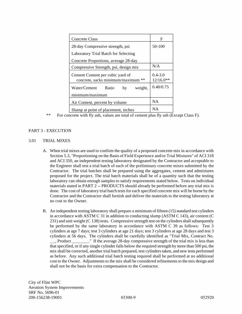
City of Flint WPC
Aeration System Improvements
SRF No. 5696-01
200-156238-19001 03300-9 052920
Concrete Class F
28-day Compressive strength, psi 50-100
Laboratory Trial Batch for Selecting
Concrete Proportions, average 28-day
Compressive Strength, psi, design mix N/A
Cement Content per cubic yard of 0.4-3.0
concrete, sacks minimum/maximum ** 12/16.0**
Water/Cement Ratio by weight,
minimum/maximum
0.40/0.75
Air Content, percent by volume NA
Slump at point of placement, inches NA
** For concrete with fly ash, values are total of cement plus fly ash (Except Class F).
PART 3 - EXECUTION
3.01 TRIAL MIXES
A. When trial mixes are used to confirm the quality of a proposed concrete mix in accordance with
Section 5.3, "Proportioning on the Basis of Field Experience and/or Trial Mixtures" of ACI 318
and ACI 350, an independent testing laboratory designated by the Contractor and acceptable to
the Engineer shall test a trial batch of each of the preliminary concrete mixes submitted by the
Contractor. The trial batches shall be prepared using the aggregates, cement and admixtures
proposed for the project. The trial batch materials shall be of a quantity such that the testing
laboratory can obtain enough samples to satisfy requirements stated below. Tests on individual
materials stated in PART 2 -- PRODUCTS should already be performed before any trial mix is
done. The cost of laboratory trial batch tests for each specified concrete mix will be borne by the
Contractor and the Contractor shall furnish and deliver the materials to the testing laboratory at
no cost to the Owner.
B. An independent testing laboratory shall prepare a minimum of fifteen (15) standard test cylinders
in accordance with ASTM C 31 in addition to conducting slump (ASTM C 143), air content (C
231) and unit weight (C 138) tests. Compressive strength test on the cylinders shall subsequently
be performed by the same laboratory in accordance with ASTM C 39 as follows: Test 3
cylinders at age 7 days; test 3 cylinders at age 21 days; test 3 cylinders at age 28 days and test 3
cylinders at 56 days. The cylinders shall be carefully identified as "Trial Mix, Contract No.
, Product ." If the average 28-day compressive strength of the trial mix is less than
that specified, or if any single cylinder falls below the required strength by more than 500 psi, the
mix shall be corrected, another trial batch prepared, test cylinders taken, and new tests performed
as before. Any such additional trial batch testing required shall be performed at no additional
cost to the Owner. Adjustments to the mix shall be considered refinements to the mix design and
shall not be the basis for extra compensation to the Contractor.

City of Flint WPC
Aeration System Improvements
SRF No. 5696-01
200-156238-19001 03300-10 052920
3.02 PRODUCTION OF CONCRETE
A. All concrete shall be machine mixed. Hand mixing of concrete will not be permitted. The
Contractor may supply concrete from a ready mix plant or from a site mixed plant. In selecting
the source for concrete production the Contractor shall carefully consider its capability for
providing quality concrete at a rate commensurate with the requirements of the placements so
that well bonded, homogenous concrete, free of cold joints, is assured.
B. Ready-Mixed Concrete
1. At the Contractor's option, ready-mixed concrete may be used meeting the requirements for
materials, batching, mixing, transporting, and placing as specified herein and in accordance
with ASTM C 94.
2. Truck mixers shall be equipped with electrically-actuated counters by which the number of
revolutions of the drum or blades may be readily verified. The counter shall be of the
resettable, recording type, and shall be mounted in the driver's cab. The counters shall be
actuated at the time of starting mixers at mixing speeds.
3. Each batch of concrete shall be mixed in a truck mixer for not less than 100 revolutions of
the drum or blades at the rate of rotation designated by the manufacturer of equipment.
Additional mixing, if any, shall be at the speed designated by the manufacturer of the
equipment as agitating speed. All materials including mixing water shall be in the mixer
drum before actuating the revolution counter for determining the number of revolutions of
mixing.
4. Truck mixers and their operation shall be such that the concrete throughout the mixed batch,
as discharged, is within acceptable limits of uniformity with respect to consistency, mix and
grading. If slump tests taken at approximately the 1/4 and 3/4 points of the load during
discharge give slumps differing by more than one inch when the specified slump is 3 inches
or less, or if they differ by more than 2 inches when the specified slump is more than 3
inches, the mixer shall not be used on the work unless the causing condition is corrected and
satisfactory performance is verified by additional slump tests. All mechanical details of the
mixer, such as water measuring and discharge apparatus, condition of the blades, speed of
rotation, general mechanical condition of the unit and clearance of the drum, shall be
checked before a further attempt to use the unit will be permitted.
5. Ready-mixed concrete shall be delivered to the site for the work and discharge shall be
completed before the drum has been revolved 300 revolutions and within the time
requirements stated in Article 3.03 of this Section.
6. Each and every concrete delivery shall be accompanied by a delivery ticket containing at
least the following information:
a. Date and truck number
b. Ticket number
c. Mix designation of concrete
d. Cubic yards of concrete
e. Cement brand, type and weight in pounds
f. Weight in pounds of fine aggregate (sand)
g. Weight in pounds of coarse aggregate (stone)
h. Air entraining agent, brand, and weight in pounds and ounces
i. Other admixtures, brand, and weight in pounds and ounces
j. Water, in gallons, stored in attached tank
k. Water, in gallons, maximum that can be added without exceeding design
water/cement ratio
City of Flint WPC
Aeration System Improvements
SRF No. 5696-01
200-156238-19001 03300-11 052920
l. Water, in gallons, actually used (by truck driver)
m. Time of loading
n. Time of delivery to job (by truck driver)
7. Any truck delivering concrete to the job site, which is not accompanied by a delivery ticket
showing the above information will be rejected and such truck shall immediately depart from
the job site.
8. The use of non-agitating equipment for transporting ready-mixed concrete will not be
permitted. Combination truck and trailer equipment for transporting ready-mixed concrete
will not be permitted. The quality and quantity of materials used in ready-mixed concrete
and in batch aggregates shall be subject to continuous inspection at the batching plant by the
Engineer.
C. Site Mixed Concrete
1. Scales for weighing concrete ingredients shall be accurate when in use within ±0.4 percent of
their total capacities. Standard test weights shall be available to permit checking scale
accuracy.
2. Operation of batching equipment shall be such that the concrete ingredients are consistently
measured within the following tolerances:
a. Cement, fly ash, or slag cement ± 1 percent
b. Water ± 1 percent
c. Aggregates ± 2 percent
d. Admixtures ± 3 percent
3. Each batch shall be so charged into the mixer that some water will enter in advance of the
cement and aggregates. Water shall continue for a period which may extend to the end of the
first 25 percent of the specified mixing time. Controls shall be provided to prevent batched
ingredients from entering the mixer before the previous batch has been completely
discharged.
4. The concrete shall be mixed in a batch mixer capable of thoroughly combining the
aggregates, cement, and water into a uniform mass within the specified mixing time, and of
discharging the concrete without harmful segregation. The mixer shall bear a manufacturer's
rating plate indicating the rate capacity and the recommended revolutions per minute and
shall be operated in accordance therewith.
5. Mixers with a rate capacity of 1 cu.yd. or larger shall conform to the requirements of the
Plant Mixer Manufacturers' Division of the Concrete Plant Manufacturers' Bureau.
6. Except as provided below, batches of 1 cu. yd. or less shall be mixed for not less than 1
minute. The mixing time shall be increased 15 seconds for each cubic yard or fraction
thereof of additional capacity.
7. Shorter mixing time may be permitted provided performance tests made in accordance with
of ASTM C 94 indicate that the time is sufficient to produce uniform concrete.
8. Controls shall be provided to insure that the batch cannot be discharged until the required
mixing time has elapsed. At least three-quarters of the required mixing time shall take place
after the last of the mixing water has been added.
9. The interior of the mixer shall be free of accumulations that will interfere with mixing action.
Mixer blades shall be replaced when they have lost 10 percent of their original height.
10. Air-entraining admixtures and other chemical admixtures shall be charged into the mixer as
solutions and shall be measured by means of an approved mechanical dispensing device.
The liquid shall be considered a part of the mixing water. Admixtures that cannot be added
in solution may be weighed or may be measured by volume if so recommended by the
manufacturer.
City of Flint WPC
Aeration System Improvements
SRF No. 5696-01
200-156238-19001 03300-12 052920
11. If two or more admixtures are used in the concrete, they shall be added separately to avoid
possible interaction that might interfere with the efficiency of either admixture or adversely
affect the concrete.
12. Addition of retarding admixtures shall be completed within 1 minute after addition of water
to the cement has been completed, or prior to the beginning of the last three-quarters of the
required mixing, whichever occurs first. Retarding admixtures shall not be used unless
approved by the Engineer.
13. Concrete shall be mixed only in quantities for immediate use and within the time and mixing
requirements of ASTM C 94.
3.03 CONCRETE PLACEMENT
A. No concrete shall be placed prior to approval of the concrete mix design. Concrete placement
shall conform to the recommendations of ACI 304.
B. Prior to concrete placement, all reinforcement shall be securely and properly fastened in its
correct position. Formwork shall be clean, oiled and form ties at construction joints shall be
retightened. All bucks, sleeves, castings, hangers, pipe, conduits, bolts, anchors, wire, and any
other fixtures required to be embedded therein shall be in place. Forms for openings to be left in
the concrete shall be in place and anchored by the Contractor. All loose debris in bottoms of
forms or in keyways shall be removed and all debris, water, snow, ice and foreign matter shall be
removed from the space to be occupied by the concrete. The Contractor shall notify the Engineer
in advance of placement, allowing sufficient time for a concurrent inspection and for any
corrective measures which are subsequently required.
C. On horizontal joints where concrete is to be placed on hardened concrete, flowing concrete
containing a high range water reducing admixture shall be placed with a slump not less than 8
inches for the initial placement at the base of the wall. This concrete shall be worked well into
the irregularities of the hard surface.
D. All concrete shall be placed during the daylight hours except with the consent of the Engineer. If
special permission is obtained to carry on work during the night, adequate lighting must be
provided.
E. When concrete arrives at the project with slump below that suitable for placing, as indicated by
the Specifications, water may be added to bring the concrete within the specified slump range
provided that the design water-cement ratio is not exceeded. The water shall be incorporated by
additional mixing equal to at least half of the total mixing required. Water may be added only to
full trucks. On-site tempering shall not relieve the Contractor from furnishing a concrete mix
that meets all specified requirements.
F. Concrete shall be conveyed as rapidly as practicable to the point of deposit by methods which
prevent the separation or loss of the ingredients. It shall be so deposited that rehandling will be
unnecessary. Discharge of the concrete to its point of deposit shall be completed within
90 minutes after the addition of the cement to the aggregates. In hot weather, or under conditions
contributing to quick stiffening of the concrete, the time between the introduction of the cement
to the aggregates and discharge shall not exceed the requirements stated in Article 3.09 of this
Section.

City of Flint WPC
Aeration System Improvements
SRF No. 5696-01
200-156238-19001 03300-13 052920
G. Where concrete is conveyed to position by chutes, a practically continuous flow in the chute shall
be maintained. The angle and discharge arrangement of the chute shall be such as to prevent
segregation of the concrete ingredients. The delivery end of the chute shall be as close as
possible to the point of deposit and in no case shall the free pour from the delivery end of the
chute exceed five feet, unless approved otherwise by Engineer.
H. Special care must be exercised to prevent splashing of forms or reinforcement with concrete, and
any such splashes or accumulations of hardened or partially hardened concrete on the forms or
reinforcement above the general level of the concrete already in place must be removed before
the work proceeds. Concrete shall be placed in all forms in such way as to prevent any
segregation.
I. Placing of concrete shall be so regulated that the pressure caused by the wet concrete shall not
exceed that used in the design of the forms.
J. All concrete for walls shall be placed through openings in the form spaced at frequent intervals or
through tremies (heavy duct canvas, rubber, etc.), equipped with suitable hopper heads. Tremies
shall be of variable lengths so the free fall shall not exceed five (5) feet and a sufficient number
shall be placed in the form to ensure the concrete is kept level at all times.
K. When placing concrete which is to be exposed, sufficient illumination shall be provided in the
interior of the forms so the concrete, at places of deposit, is visible from deck and runways.
L. Concrete shall be placed so as to thoroughly embed all reinforcement, inserts, and fixtures.
M. When forms are removed, surfaces shall be even and dense, free from aggregate pockets or
honeycomb. To achieve this, concrete shall be consolidated using mechanical vibration,
supplemented by forking and spading by hand in the corners and angle of forms and along form
surfaces while the concrete is plastic under the vibratory action. Consolidation shall conform to
ACI 309.
N. Mechanical vibration shall be applied directly to the concrete, unless otherwise approved by the
Engineer. The bottom of vibrators used on floor slabs must not be permitted to ride the form
supporting the slab. Vibration shall be applied at the point of deposit and in the area of freshly
placed concrete by a vertical penetration of the vibrator. Vibrators shall not be used to move
concrete laterally within the forms.
O. The intensity of vibration shall be sufficient to cause settlement of the concrete into place and to
produce monolithic joining with the preceding layer. It shall be of sufficient duration to
accomplish thorough compaction and complete embedment of reinforcement and fixtures with a
vibrator transmitting not less than 7,500 impulses per minute. Since the duration of vibration per
square foot of surface is dependent on the frequency (impulses per minute), size of vibrator, and
slump of concrete, the length of time must therefore be determined in the field. Vibration,
however, shall not be continued in any one location to the extent that pools of grout are formed.
P. Care shall be taken to prevent cold joints when placing concrete in any portion of the work. The
concrete placing rate shall be such as to ensure that each layer is placed while the previous layer
is soft or plastic, so that the two layers can be made monolithic by penetration of the vibrators.

City of Flint WPC
Aeration System Improvements
SRF No. 5696-01
200-156238-19001 03300-14 052920
Maximum thickness of concrete layers shall be 18 inches. The surface of the concrete shall be
level whenever a run of concrete is stopped.
Q. To prevent featheredges, construction joints located at the tops of horizontal lifts near sloping
exposed concrete surfaces shall be inclined near the exposed surface, so the angle between such
inclined surface and the exposed concrete surface will be not less than 50°.
R. In placing unformed concrete on slopes, the concrete shall be placed ahead of a non-vibrated slip-
form screed extending approximately 2-1/2 feet back from its leading edge. The method of
placement shall provide a uniform finished surface with the deviation from the straight line less
than 1/8 inch in any concrete placement. Concrete ahead of the slip-form screed shall be
consolidated by internal vibrators so as to ensure complete filling under the slip-form. Prior to
placement of concrete on sloped walls or slabs, the Contractor shall submit a plan specifically
detailing methods and sequence of placements, proposed concrete screed equipment, location of
construction joints and waterstops, and/or any proposed deviations from the aforementioned to
the Engineer for review and approval.
S. Concrete shall not be placed during rains sufficiently heavy or prolonged to wash mortar from
coarse aggregate on the forward slopes of the placement. Once placement of concrete has
commenced in a block, placement shall not be interrupted by diverting the placing equipment to
other uses.
3.04 ORDER OF PLACING CONCRETE
A. In order to minimize the effects of shrinkage, the concrete shall be placed in units as bounded by
construction joints shown on the Drawings and maximum lengths as indicated on Drawings.
Where required on the Drawings and wherever else practical, the placing of such units shall be
done in a strip pattern in accordance with ACI 302.1. A minimum of 72 hours shall pass prior to
placing concrete directly adjacent to previously placed concrete.
3.05 CONCRETE WORK IN COLD WEATHER
A. Cold weather concreting procedures shall conform to the requirements of ACI 306.
B. In addition to the requirements of ACI 306, concrete placed at any time when air temperature is
40°F or lower shall have a minimum temperature, as placed, of 55°F for placements less than 12"
thick, 50°F for placements 12" to 36" thick, and 45°F for placements greater than 36" thick. The
temperature of the concrete as placed shall not exceed the aforementioned minimum values by
more than 20°F, unless otherwise approved by the Engineer.
C. All aggregate and water shall be preheated. Precautions shall be taken to avoid the possibility of
flash set when aggregate or water are heated to a temperature in excess of 100°F in order to meet
concrete temperature requirements. The addition of admixtures to the concrete to prevent
freezing is not permitted. All reinforcement, forms, and concrete accessories with which the
concrete is to come in contact shall be defrosted by an approved method. No concrete shall be
placed on frozen ground.

City of Flint WPC
Aeration System Improvements
SRF No. 5696-01
200-156238-19001 03300-15 052920
3.06 CONCRETE WORK IN HOT WEATHER
A. Hot weather concreting procedures shall conform to the requirements of ACI 305.
B. When air temperatures exceed 85°F., or when extremely dry conditions exist even at lower
temperatures, particularly if accompanied by high winds, the Contractor and his concrete supplier
shall exercise special and precautionary measures in preparing, delivering, placing, finishing,
curing and protecting the concrete mix. The Contractor shall consult with the Engineer regarding
such measures prior to each day's placing operation and the Engineer reserves the right to modify
the proposed measures consistent with the requirements of this Section of the Specifications. All
necessary materials and equipment shall be on hand an in position prior to each placing
operation.
C. Preparatory work at the job site shall include thorough wetting of all forms, reinforcing steel and,
in the case of slab pours on ground or subgrade, spraying the ground surface on the preceding
evening and again just prior to placing. No standing puddles of water shall be permitted in those
areas which are to receive the concrete.
D. The temperature of the concrete mix when placed shall not exceed 90°F.
E. Temperature of mixing water and aggregates shall be carefully controlled and monitored at the
supplier's plant, with haul distance to the job site being taken into account. Stockpiled aggregates
shall, if necessary, be shaded from the sun and sprinkled intermittently with water. If ice is used
in the mixing water for cooling purposes, it must be entirely melted prior to addition of the water
to the dry mix.
F. Delivery schedules shall be carefully planned in advance so that concrete is placed as soon as
practical after it is properly mixed. For hot weather concrete work (air temperature greater than
85°F), discharge of the concrete to its point of deposit shall be completed within 60 minutes from
the time the concrete is batched.
G. The Contractor shall arrange for an ample work force to be on hand to accomplish transporting,
vibrating, finishing, and covering of the fresh concrete as rapidly as possible.
3.07 QUALITY CONTROL
A. Field Testing of Concrete
1. The Contractor shall coordinate with the Owner’s testing firm personnel as required for
concrete testing.
2. Concrete for testing shall be supplied by the Contractor at no additional cost to the Owner,
and the Contractor shall provide assistance to the testing laboratory in obtaining samples.
The Contractor shall dispose of and clean up all excess material.
3. For every placement of concrete that is 10 cubic yards or less, the following tests shall be
performed (as described in paragraphs B through E below):
a. Consistency
b. Unit Weight
c. Air content
d. Compressive Strength
e. Temperature

City of Flint WPC
Aeration System Improvements
SRF No. 5696-01
200-156238-19001 03300-16 052920
4. For every placement of concrete that is larger than 10 cubic yards, the following tests shall
be performed for every 50 cubic yards (as described in paragraphs B through E below):
a. Consistency – test the first truck and one additional truck randomly selected by the
Owner’s Resident Project Representative (RPR).
b. Unit Weight – test one truck randomly selected by the RPR
c. Air content - test the first truck and one additional truck randomly selected by the RPR.
d. Compressive Strength - test one truck randomly selected by the RPR
e. Temperature - test one truck randomly selected by the RPR
The sampling of concrete is approved at the truck discharge. If a concrete pump is employed,
the Contractor is advised that 1.5-3.0% air is lost in pumping and such should be accounted
for at the point of testing. Therefore, the air content should be adjusted to ensure that the air
content meets the specification at the point of placement.
The first truck is defined as the first truck as accepted by the RPR. The RPR shall have the
authority of the Owner to accept or reject all concrete.
5. Sampling is at the discretion of the RPR.
6. Additional testing may be required as deemed necessary by the Owner.
B. Consistency
1. The consistency of the concrete will be checked by the Owner’s testing firm by standard
slump cone tests. The Contractor shall make any necessary adjustments in the mix as the
Owner or Engineer may direct and shall upon written order suspend all placing operations in
the event the consistency does not meet the intent of the specifications. No payment shall be
made for any delays, material or labor costs due to such eventualities.
2. Slump tests shall be made in accordance with ASTM C 143.
3. Concrete with a specified nominal slump shall be placed having a slump within 1” (higher or
lower) of the specified slump. Concrete with a specified maximum slump shall be placed
having a slump less than the specified slump.
C. Unit Weight
1. Samples of freshly mixed concrete shall be tested for unit weight by the Owner’s testing firm
in accordance with ASTM C 138.
D. Air Content
1. Samples of freshly mixed concrete will be tested for entrained air content by the Owner’s
testing firm in accordance with ASTM C 231.
2. In the event test results are outside the limits specified, additional testing shall occur. Upon
discovery of incorrect air entrainment, the concrete shall be removed from the jobsite.
E. Compressive Strength
1. Samples of freshly mixed concrete will be taken by the Owner’s testing firm and tested for
compressive strength in accordance with ASTM C 172, C 31 and C 39, except as modified
herein.
2. Each sampling shall consist of at least five (5) 6x12 cylinders or (8) 4x8 cylinders. Each
cylinder shall be identified by a tag, which shall be hooked or wired to the side of the
container. The Owner’s testing firm will fill out the required information on the tag, and the
Contractor shall satisfy himself that such information shown is correct.

City of Flint WPC
Aeration System Improvements
SRF No. 5696-01
200-156238-19001 03300-17 052920
3. The Contractor shall be required to furnish labor to the Owner for assisting in preparing test
cylinders for testing. The Contractor shall provide approved curing boxes for storage of
cylinders on site. The insulated curing box shall be of sufficient size and strength to contain
all the specimens made in any four consecutive working days and to protect the specimens
from falling over, being jarred or otherwise disturbed during the period of initial curing. The
box shall be erected, furnished and maintained by the Contractor. Such box shall be
equipped to provide the moisture and to regulate the temperature necessary to maintain the
proper curing conditions required by ASTM C 31. Such box shall be located in an area free
from vibration such as pile driving and traffic of all kinds and such that all specimen are
shielded from direct sunlight and/or radiant heating sources. No concrete requiring
inspection shall be delivered to the site until such storage curing box has been provided.
Specimens shall remain undisturbed in the curing box until ready for delivery to the testing
laboratory but not less than sixteen hours.
4. The Contractor shall be responsible for maintaining the temperatures of the curing box
during the initial curing of test specimens with the temperature preserved between 60°F and
80°F as measured by a maximum-minimum thermometer. The Contractor shall maintain a
written record of curing box temperatures for each day curing box contains test specimens.
Temperature shall be recorded a minimum of three times a day with one recording at the start
of the work day and one recording at the end of the work day.
5. When transported, the cylinders shall not be thrown, dropped, allowed to roll, or be damaged
in any way.
F. Evaluation and Acceptance of Concrete
1. Evaluation and acceptance of the compressive strength of concrete shall be according to the
requirements of ACI 214, ACI 318, and ACI 350.
2. The strength level of concrete will be considered satisfactory if all of the following
conditions are satisfied.
a. Every arithmetic average of any three consecutive strength tests equals or exceeds the
minimum specified 28-day compressive strength for the mix (see Article 2.07).
b. No individual compressive strength test results falls below the minimum specified
strength by more than 500 psi.
c. No more than 10% of the compressive tests have strengths greater than the maximum
strength specified.
3. In the event any of the conditions listed above are not met, the mix proportions shall be
corrected for the next concrete placing operation.
4. In the event that condition 2B is not met, additional tests in accordance with Article 3.10,
paragraph H shall be performed.
5. When a ratio between 7-day and 28-day strengths has been established by these tests, the 7-
day strengths shall subsequently be taken as a preliminary indication of the 28-day strengths.
Should the 7-day test strength from any sampling be more than 10% below the established
minimum strength, the Contractor shall:
a. Immediately provide additional periods of curing in the affected area from which the
deficient test cylinders were taken.
b. Maintain or add temporary structural support as required.
c. Correct the mix for the next concrete placement operation, if required to remedy the
situation.
6. All concrete which fails to meet the ACI requirements and these specifications is subject to
removal and replacement at no additional cost to the Owner.

City of Flint WPC
Aeration System Improvements
SRF No. 5696-01
200-156238-19001 03300-18 052920
G. Additional Tests
1. In the event the 28-day test cylinders fail to meet the minimum strength requirements as
outlined in Article 3.10, paragraph F, the Contractor shall have concrete core specimens
obtained and tested from the affected area immediately.
a. Three cores shall be taken by the Owner’s testing firm for each sample in which the
strength requirements were not met.
b. The concrete in question will be considered acceptable if the average compressive
strength of a minimum of three test core specimens taken from a given area equal or
exceed 85% of the specified 28-day strength and if the lowest core strength is greater
than 75% of the specified 28-day strength.
2. Concrete placed with compressive strengths greater than the maximum strength specified
shall be removed and replaced or repaired as deemed necessary by the Engineer.
3.08 CARE AND REPAIR OF CONCRETE
A. The Contractor shall protect all concrete against injury or damage from excessive heat, lack of
moisture, overstress, or any other cause until final acceptance by the Owner. Particular care shall
be taken to prevent the drying of concrete and to avoid roughening or otherwise damaging the
surface. Care shall be exercised to avoid jarring forms or placing any strain on the ends of
projecting reinforcing bars. Any concrete found to be damaged, or which may have been
originally defective, or which becomes defective at any time prior to the final acceptance of the
completed work, or which departs from the established line or grade, or which, for any other
reason, does not conform to the requirements of the Contract Documents, shall be satisfactorily
repaired or removed and replaced with acceptable concrete at no additional cost to the Owner.
B. Areas of honeycomb shall be chipped back to sound concrete and repaired as directed by the
Engineer.
C. Concrete formwork blowouts or unacceptable deviations in tolerances for formed surfaces due to
improperly constructed or misaligned formwork shall be repaired as directed by the Engineer.
Bulging or protruding areas, which result from slipping or deflecting forms shall be ground flush
or chipped out and redressed as directed by the Engineer.
D. Areas of concrete in which cracking, spalling, or other signs of deterioration develop prior to
final acceptance shall be removed and replaced, or repaired as directed by the Engineer. This
stipulation includes concrete that has experienced cracking due to drying or thermal shrinkage of
the concrete. Structural cracks shall be repaired using an epoxy injection system approved by the
Engineer. Non-structural cracks shall be repaired using a hydrophilic resin pressure injected
grout system approved by the Engineer, unless other means of repair are deemed necessary and
approved by the Engineer. Extensive repair or replacement will be considered for concrete
placed having compressive strengths greater than maximum strength specified. All repair work
shall be performed at no additional cost to the Owner.

City of Flint WPC
Aeration System Improvements
SRF No. 5696-01
200-156238-19001 03300-19 052920
E. Concrete which fails to meet the strength requirements as outlined in Article 3.10, paragraph F,
will be analyzed by the Engineer as to its adequacy based upon loading conditions, resultant
stresses and exposure conditions for the particular area of concrete in question. If the concrete in
question is found unacceptable based upon this analysis, that portion of the structure shall be
strengthened or replaced by the Contractor at no additional cost to the Owner. The method of
strengthening or extent of replacement shall be directed by the Engineer.
END OF SECTION

City of Flint WPC
Aeration System Improvements
SRF No. 5696-01
200-156238-19001 03350-1 052920
SECTION 03350 - CONCRETE FINISHES
PART 1 - GENERAL
1.01 REQUIREMENTS
A. Furnish all materials, labor, and equipment required to provide finishes of all concrete surfaces specified
herein and shown on the Drawings.
1.02 RELATED WORK SPECIFIED ELSEWHERE
A. Section 03100 - Concrete Formwork
B. Section 03300 - Cast-in-Place Concrete
1.03 REFERENCE SPECIFICATIONS, CODES AND STANDARDS
A. Without limiting the generality of the other requirements of the specifications, all work herein shall
conform to the applicable requirements of the following documents. All referenced specifications, codes,
and standards refer to the most current issue available at the time of Bid.
1. ACI 301 - Specifications for Structural Concrete for Buildings
2. ACI 318 - Building Code Requirements for Structural Concrete
1.04 SUBMITTALS
A. Submit the following in accordance with Section 01330 - Submittals.
1. Manufacturer's literature on all products specified herein.
PART 2 - PRODUCTS
NOT USED
PART 3 - EXECUTION
3.01 FINISHES ON FORMED CONCRETE SURFACES
A. After removal of forms, the finishes described below shall be applied in accordance with Article 3.05 -
Concrete Finish Schedule. Unless the finish schedule specifies otherwise, all surfaces shall receive at
least a Type I finish. The Engineer shall be the sole judge of acceptability of all concrete finish work.
1. Type I - Rough: All fins, burrs, offsets, marks and all other projections left by the forms shall be
removed. Projections, depressions, etc. below finished grade required to be removed will only be
those greater than ¼-inch. All holes left by removal of ends of ties, and all other holes, depressions,
bugholes, air/blow holes or voids shall be filled solid with cement grout after first being thoroughly
wetted and then struck off flush. The only holes below grade to be filled will be tie holes and any
other holes larger than ¼-inch in any dimension. Honeycombs shall be chipped back to solid

City of Flint WPC
Aeration System Improvements
SRF No. 5696-01
200-156238-19001 03350-2 052920
concrete and repaired as directed by the Engineer. All holes shall be filled with tools, such as
sponge floats and trowels, that will permit packing the hole solidly with cement grout. Cement
grout shall consist of one part cement to three parts sand, epoxy bonding agent (for tie holes only)
and the amount of mixing water shall be as little as consistent with the requirements of handling
and placing. Color of cement grout shall match the adjacent wall surface.
2. Type II - Grout Cleaned: Where this finish is required, it shall be applied after completion of Type
I finish. After the concrete has been predampened, a slurry consisting of one part cement (including
an appropriate quantity of white cement in order to produce a color matching the surrounding
concrete) and 1-1/2 parts sand passing the No. 16 sieve, by damp loose volume, shall be spread over
the surface with clean burlap pads or sponge rubber floats. Mix proportions shall be submitted to
the Engineer after a sample of the work is established and accepted. Any surplus shall be removed
by scraping and then rubbing with clean burlap.
3. Type III - Smooth Rubbed: Where this finish is required, it shall be applied after the completion of
the Type I finish. No rubbing shall be done before the concrete is thoroughly hardened and the mortar
used for patching is firmly set. A smooth, uniform surface shall be obtained by wetting the surface
and rubbing it with a carborundum stone to eliminate irregularities. Unless the nature of the
irregularities requires it, the general surface of the concrete shall not be cut into. Corners and edges
shall be slightly rounded by the use of the carborundum stone. Brush finishing or painting with grout
or neat cement will not be permitted. A 100 square foot example shall be established at the beginning
of the project to establish acceptability.
3.02 SLAB AND FLOOR FINISHES
A. The finishes described below shall be applied to floors, slabs, flow channels and top of walls in
accordance with Article 3.05 - Concrete Finish Schedule. The Engineer shall be the sole judge of
acceptability of all such finish work.
1. Type "A" - Screeded: This finish shall be obtained by placing screeds at frequent intervals and
striking off to the surface elevation required. When a Type "F" finish is subsequently to be applied,
the surface of the screeded concrete shall be roughened with a stiff brush or rake prior to final set.
2. Type "B" - Wood or Magnesium Floated: This finish shall be obtained after completion of a Type
"A" finish by working a previously screeded surface with a wood or magnesium float or until the
desired texture is reached. Floating shall begin when the water sheen has disappeared and when the
concrete has sufficiently hardened so that a person's foot leaves only a slight imprint. If wet spots
occur, water shall be removed with a squeegee. Care shall be taken to prevent the formation of
laitance and excess water on the finished surface. All edges shall be edged with an 1/8-inch tool as
directed by the Engineer. The finished surface shall be true, even, and free from blemishes and any
other irregularities.
3. Type "C" - Cork Floated: This finish shall be similar to Type "B" but slightly smoother than that
obtained with a wood float. It shall be obtained by power or band floating with cork floats.
4. Type "D" - Steel Troweled: This finish shall be obtained after completion of a Type "B" finish. When
the concrete has hardened sufficiently to prevent excess fine material from working to the surface, the
surface shall be compacted and smoothed with not less than two thorough and complete steel troweling
operations. In areas which are to receive a floor covering such as tile, resilient flooring, or carpeting, the
applicable Specification Sections and Contract Drawings shall be reviewed for the required finishes and
degree of flatness. In areas that are intermittently wet such as pump rooms, only one troweling
operation is required to provide some trowel marks for slip resistance. All edges shall be edged with an
1/8-inch tool as directed by the Engineer. The finish shall be brought to a smooth, dense surface, free
from defects and blemishes.

City of Flint WPC
Aeration System Improvements
SRF No. 5696-01
200-156238-19001 03350-3 052920
5. Type "E" - Broom or Belt: This finish shall provide the surface with a transverse scored texture by
drawing a broom or burlap belt across the surface immediately after completion of a Type "B"
finish. All edges shall be edged with an 1/8-inch tool as directed by the Engineer.
6. Type "F" - Swept in Grout Topping: This finish shall be applied after a completion of a Type "A"
finish. The concrete surface shall be properly cleaned, washed, and coated with a mixture of water
and Portland Cement. Cement grout in accordance with Section 03600 shall then be plowed and
swept into neat conformance with the blades or arms of the apparatus by turning or rotating the
previously positioned mechanical equipment. Special attention shall be paid to true grades, shapes
and tolerances as specified by the manufacturer of the equipment. Before beginning this finish, the
Contractor shall notify the Engineer and the equipment manufacturer of the details of the operation
and obtain approval and recommendations.
7. Type “G” Hardened Finish: This finish shall be applied after completion of a Type “B” or Type
“C” finish and prior to application of a Type “D” finish. Hardeners shall be applied in strict
accordance with the manufacturer’s requirements. Hardeners shall be applied using a mechanical
spreader. The hardener shall be applied in two shakes with the first shake comprising 2/3 of the
total amount. Type “D” finish shall be applied following completion of application of the hardener.
a. Non-metallic floor hardener shall be applied where specifically required on the Contract
Drawings at the rate of 1.0 pounds/ft.2.
b. Non-oxidizing heavy-duty metallic floor hardener shall be applied at the loading docks and
where specifically required on the Contract Drawings or specified herein at the rate of 1.5
pounds/ft.2.
8. Type "H" - Non-Slip Finish: This finish shall be provided by applying a non-slip shake-on aggregate
concurrently with the application of a Type "D" finish. Application procedure shall be in accordance
with manufacturer's instructions.
9. Type "J" - Raked Finish: This finish shall be provided by raking the surface as soon as the
condition of the concrete permits by making depressions of ±1/4 inch.
3.03 FINISHES ON EQUIPMENT PADS
A. Formed surfaces of equipment pads shall receive a Type III finish.
B. Top surfaces of equipment pads, except those surfaces subsequently required to receive grout and
support equipment bases, shall receive a Type "D" finish, unless otherwise noted. Surfaces which will
later receive grout shall, before the concrete takes its final set, be made rough by removing the sand and
cement that accumulates on the top to the extent that the aggregate will be exposed with irregular
indentations in the surface up to 1/2 inch deep.

City of Flint WPC
Aeration System Improvements
SRF No. 5696-01
200-156238-19001 03350-4 052920
3.05 CONCRETE FINISH SCHEDULE
Item Type of Finish
Concrete surfaces indicated to receive textured I
Inner face of walls of tanks, flow channels, wet wells, perimeter walls, and
miscellaneous concrete structures:
From 1 foot below water surface to bottom of wall I
From top of wall to 1 foot below water surface I
Exterior concrete walls below grade
Exterior exposed concrete walls grout cleaned smooth surface
I
II
Exterior exposed concrete ceilings, beams, manholes, hand holes,
miscellaneous structures and columns (including top of wall) to one foot
below grade. All other exposed concrete surfaces not specified elsewhere
I
All interior exposed concrete walls and vertical surfaces I
Interior exposed ceiling, including beams III
Floors of process equipment tanks or basins, wetwells, flow channels and
slabs to receive roofing material or waterproof membranes
B
All interior finish floors of buildings and structures and walking surfaces
which will be continuously or intermittently wet
D
All interior finish floors of buildings and structures which are not
continuously or intermittently wet
D
Floors to receive tile, resilient flooring, or carpeting D
Exterior concrete sidewalks, steps, ramps, decks, slabs on grade and landings
exposed to weather
E
Floors of process equipment tanks indicated on Drawings to receive grout
topping
F
Garage and storage area floors G
Precast concrete form panels, hollow core planks, double tees to receive
concrete topping
J
END OF SECTION
City of Flint WPC
Aeration System Improvements
SRF No. 5696-01
200-156238-19001 03370-1 052920
SECTION 03370 - CONCRETE CURING
PART 1 - GENERAL
1.01 REQUIREMENTS
A. Protect all freshly deposited concrete from premature drying and from the weather elements. The
concrete shall be maintained with minimal moisture loss at a relatively constant temperature for a period
of time necessary for the hydration of the cement and proper hardening of the concrete in accordance
with the requirements specified herein.
1.02 RELATED WORK SPECIFIED ELSEWHERE
A. Section 03100 - Concrete Formwork
B. Section 03300 - Cast-In-Place Concrete
C. Section 03350 - Concrete Finishes
1.03 REFERENCE SPECIFICATIONS, CODES AND STANDARDS
A. Without limiting the generality of the other requirements of the specifications, all work herein shall
conform to the applicable requirements of the following documents. All referenced specifications,
codes, and standards refer to the most current issue available at the time of Bid.
1. ACI 301 - Specifications for Structural Concrete for Buildings
2. ACI 304 - Guide for Measuring, Mixing, Transporting, and Placing Concrete
3. ACI 305 - Hot Weather Concreting
4. ACI 306 - Cold Weather Concreting
5. ACI 308 - Standard Practice for Curing Concrete
6. ASTM C171 - Standard Specifications for Sheet Materials for Curing Concrete
7. ASTM C309 - Standard Specification for Liquid Membrane-Forming Compounds for Curing
Concrete
8. Federal Specification TT-C-800
1.04 SUBMITTALS
A. Submit the following in accordance with Section 01330, Submittals.
1. Proposed procedures for protection of concrete under wet weather placement conditions.
2. Proposed normal procedures for protection and curing of concrete.
3. Proposed special procedures for protection and curing of concrete under hot and cold weather
conditions.
4. Proposed method of measuring concrete surface temperature changes.
5. Manufacturer's literature and material certification for proposed curing compounds.

City of Flint WPC
Aeration System Improvements
SRF No. 5696-01
200-156238-19001 03370-2 052920
PART 2 - PRODUCTS
2.01 LIQUID MEMBRANE-FORMING CURING COMPOUND
A. Clear curing and sealing compound shall be a clear styrene acrylate type complying with ASTM C
1315, Type 1, Class A with a minimum solids content of 30%. Moisture loss shall not be greater than
0.40 kg/m2 when applied at 300 sq.ft./gal. Manufacturer’s certification is required. Acceptable
products are Super Diamond Clear VOX by the Euclid Chemical Company, Sonneborn Kure N Seal 30
by BASF Construction Chemicals, and Cure & Seal 30 Plus by Symons Corporation.
B. Where specifically approved by Engineer, on slabs to receive subsequent applied finishes, compound
shall conform to ASTM C 309. Acceptable products are “Kurez DR VOX” or “Kurez W VOX” by the
Euclid Chemical Company. Install in strict accordance with manufacturer’s requirements.
PART 3 - EXECUTION
3.01 PROTECTION AND CURING
A. All freshly placed concrete shall be protected from the elements, flowing water and from defacement of
any nature during construction operations.
B. As soon as the concrete has been placed and horizontal top surfaces have received their required finish,
provision shall be made for maintaining the concrete in a moist condition for at least a 5-day period
thereafter except for high early strength concrete, for which the period shall be at least the first three
days after placement. Horizontal surfaces shall be kept covered, and intermittent, localized drying will
not be permitted.
C. Walls that will be exposed on one side with either fluid or earth backfill on the opposite side shall be
continuously wet cured for a minimum of five days. Use of a curing compound will not be acceptable
for applications of this type.
D. The Contractor shall use one of the following methods to insure that the concrete remains in a moist
condition for the minimum period stated above.
1. Ponding or continuous fogging or sprinkling.
2. Application of mats or fabric kept continuously wet.
3. Continuous application of steam (under 150°F).
4. Application of sheet materials conforming to ASTM C171.
5. If approved by the Engineer, application of a curing compound in accordance with Article 3.04.
E. The Contractor shall keep absorbent wood forms wet until they are removed. After form removal, the
concrete shall be cured by one of the methods in paragraph D.
F. Any of the curing procedures used in Paragraph 3.01-D may be replaced by one of the other curing
procedures listed in Paragraph 3.01-D after the concrete is one-day old. However, the concrete surface
shall not be permitted to become dry at any time.
City of Flint WPC
Aeration System Improvements
SRF No. 5696-01
200-156238-19001 03370-3 052920
3.02 CURING CONCRETE UNDER COLD WEATHER CONDITIONS
A. Suitable means shall be provided for a minimum of 72 hours after placing concrete to maintain it at or
above the minimum as placed temperatures specified in Section 03300, Cast-In-Place Concrete, for
concrete work in cold weather. During the 72-hour period, the concrete surface shall not be exposed to
air more than 20°F above the minimum as placed temperatures.
B. Stripping time for forms and supports shall be increased as necessary to allow for retardation in concrete
strength caused by colder temperatures. This retardation is magnified when using concrete made with
blended cements or containing fly ash or ground granulated blast furnace slag. Therefore, curing times
and stripping times shall be further increased as necessary when using these types of concrete.
C. The methods of protecting the concrete shall be approved by the Engineer and shall be such as will
prevent local drying. Equipment and materials approved for this purpose shall be on the site in
sufficient quantity before the work begins. The Contractor shall assist the Engineer by providing holes
in the forms and the concrete in which thermometers can be placed to determine the adequacy of
heating and protection. All such thermometers shall be furnished by the Contractor in quantity and type
which the Engineer directs.
D. Curing procedures during cold weather conditions shall conform to the requirements of ACI 306.
E. Protect concrete to provide continuous warm moist curing immediately after placement and during
protection period. Minimum protection period is 7 days. Maintain these temperatures:
Concrete section <12” during protection period – 55 F
Concrete section 12” to 36” during protection period – 50 F
Concrete section 36” to 72” during protection period – 45 F
At the end of the protection period, allow concrete to cool gradually to the ambient temperature.
1. Where temperature of concrete exceeds ambient by 20 degrees Fahrenheit or more, loosen forms
and leave in place for at least 24 to 48 hours before removal.
2. If water curing has been used, maintain concrete temperature for at least 24 hours after water curing
is terminated. Allow water-cured concrete to air dry for 72 hrs. before exposure to freezing
temperatures.
3.03 CURING CONCRETE UNDER HOT WEATHER CONDITIONS
A. When air temperatures exceed 85°F, the Contractor shall take extra care in placing and finishing
techniques to avoid formation of cold joints and plastic shrinkage cracking. If ordered by the Engineer,
temporary sun shades and/or windbreakers shall be erected to guard against such developments,
including generous use of wet burlap coverings and fog sprays to prevent drying out of the exposed
concrete surfaces.
B. Immediately after screeding, horizontal surfaces shall receive an application of evaporation reducer.
Apply in accordance with manufacturer's instructions. Final finish work shall begin as soon as the mix
has stiffened sufficiently to support the workmen.
C. Curing and protection of the concrete shall begin immediately after completion of the finishing
operation. Continuous moist-curing consisting of method 1 or 2 listed in paragraph 3.01D is mandatory
City of Flint WPC
Aeration System Improvements
SRF No. 5696-01
200-156238-19001 03370-4 052920
for at least the first 24 hours. Method 2 may be used only if the finished surface is not marred or
blemished during contact with the coverings.
D. At the end of the initial 24-hour period, curing and protection of the concrete shall continue for at least
four (4) additional days using one of the methods listed in paragraph 3.01D.
E. Curing procedures during hot weather conditions shall conform to the requirements of ACI 305.
3.04 USE OF CURING COMPOUND
A. Curing compound shall be used only where specifically approved by the Engineer. Curing compound
shall never be used for curing exposed walls with fluid or earth backfill on the opposite side. A
continuous wet cure for a minimum of five days is required for these applications. Curing compound
shall not be used on surfaces exposed to water in potable water storage tanks and treatment plants unless
curing compound is certified in accordance with ANSI/NSF Standard 61.
B. When permitted, the curing compound shall maintain the concrete in a moist condition for the required
time period, and the subsequent appearance of the concrete surface shall not be affected.
C. The compound shall be applied in accordance with the manufacturer's recommendations after water
sheen has disappeared from the concrete surface and after finishing operations. Maximum coverage for
the curing and sealing compound shall be 300 square feet per gallon for trowel finishes and 200 square
feet per gallon for floated or broom surfaces. Maximum coverage for compounds placed where
subsequent finishes will be applied shall be 200 square feet per gallon. For rough surfaces, apply in two
directions at right angles to each other.
3.05 EARLY TERMINATION OF CURING
A. Moisture retention measures may be terminated earlier than the specified times only when at least one
of the following conditions is met:
1. The strength of the concrete reaches 85 percent of the specified 28-day compressive strength in
laboratory-cured cylinders representative of the concrete in place, and the temperature of the in-place
concrete has been constantly maintained at 50 degrees Fahrenheit or higher.
2. The strength of concrete reaches the specified 28-day compressive strength as determined by
accepted nondestructive methods or laboratory-cured cylinder test results.
END OF SECTION
City of Flint WPC
Aeration System Improvements
SRF No. 5696-01
200-156238-19001 03930-1 052920
SECTION 03930 - REPAIR OF EXISTING CONCRETE STRUCTURES
PART 1 - GENERAL
1.01 SUMMARY
A. Section Includes: Extent of repair of existing concrete structures shown on Drawings and specified,
and includes patching loose, spalled, and unsound concrete, grouting cracks, removing debris
resulting from Work, and other Work required to produce a neat and complete job.
B. Related Documents: Drawings and general provisions of Contract, including General and
Supplementary Conditions and Division 1, apply to Work of this Section.
1.02 METHODS OF PAYMENT
A. Repair over 2 inches Deep: Measure surface area and average depth after surface preparation and
prior to beginning actual repair. ENGINEER, with CONTRACTOR, will determine the volume of
each location for repair. These measurements shall be done to the nearest inch, and then totaled for
comparison with the quantity shown on Drawings. The difference in quantities over or under those
shown, will be included in a Change Order increasing or decreasing the Contract Price noted on Bid
Form.
B. Repair Equal to or Less than 2 Inches Deep: Work shall be paid for by the square foot of surface area
repaired. Measure surface area after surface preparation and prior to beginning actual repair.
ENGINEER, with CONTRACTOR, will determine the surface area of each location or fraction of
each location for repair that is equal to or less than 2 inches deep. These measurements shall be done
to the nearest 0.1 square foot and then totaled for comparison with the quantity shown on Drawings.
The difference in quantities over or under those shown shall be included in a Change Order
increasing or decreasing the Lump Sum Bid Price noted on Bid Form.
C. Pressure Injection of Epoxy Resin: Work will be paid for by the linear foot of crack injected. These
measurements shall be done to the nearest linear foot and then totaled for comparison with the
quantity shown on Drawings. The difference in quantities over or under those shown shall be
included in a Change Order increasing or decreasing the Lump Sum Bid Price noted on Bid Form.
D. Pressure Injection of Hydrophilic Grout: Work will be paid for by the linear foot of crack injected.
These measurements shall be done to the nearest linear foot and then totaled for comparison with the
quantity shown on Drawings. The difference in quantities over or under those shown shall be
included in a Change Order increasing or decreasing the Lump Sum Bid Price noted on Bid Form.
1.03 SUBMITTALS
A. Shop Drawings: Submit in accordance with Section 01330, Shop Drawings covering the items
included under this Section. Shop Drawing submittals shall include:
1. Product data for proprietary materials and items, including patching compounds and others
requested by ENGINEER.
2. Samples of materials as requested by ENGINEER, including names, sources, and descriptions.

City of Flint WPC
Aeration System Improvements
SRF No. 5696-01
200-156238-19001 03930-2 052920
B. Material certificates in lieu of laboratory test reports on other materials. Manufacturer and
CONTRACTOR shall sign material certificates certifying that each material item complies with, or
exceeds, specified requirements.
C. Qualification Data for Installers.
1. Manufacturer’s certificates that the installer’s workers are trained and qualified for each type of
product.
2. Satisfactory experience record including references from previous applications of the specified
materials for repairs of a similar type and under similar conditions.
D. Repair Plan: Submit before Work begins.
1.04 REFERENCES
A. Codes and Standards:
1. Comply with provisions of following codes, specifications, and standards, except where more
stringent requirements are shown or specified:
a. ACI 224, Causes, Evaluation, and Repair of Cracks.
b. ACI 201, Chapter 6, "Repair of Concrete."
c. ACI 301, Specifications for Structural Concrete for Buildings.
1.05 QUALITY ASSURANCE
A. Manufacturer Qualifications: Each product manufacturer shall employ factory-trained technical
representatives who are available for consultation and Project-site inspection and assistance at no
additional cost.
B. Installer Qualifications: Entity qualified in the field of concrete repair with a minimum of 5-years
experience and employs installers and supervisors who are trained and approved by product
manufacturers to apply products used.
C. Repair Plan: Prepare a written plan for repair of cast-in-place concrete, including each phase or
process, protection of surrounding materials during operations, and control of debris and runoff
during Work. Describe in detail materials, methods, equipment, and sequence of operations to used
for each phase of the Work.
D. Materials and installed work may require testing and retesting at any time during progress of Work.
Tests, including retesting of rejected materials for installed Work, shall be done at CONTRACTOR's
expense.
E. Materials and installed work may require testing and retesting at any time during progress of Work.
Tests, including retesting of rejected materials for installed Work, shall be done at CONTRACTOR's
expense.
1.06 DELIVERY, STORAGE AND HANDLING
A. Deliver materials in manufacturer’s original, unopened, undamaged containers with identification
labels intact.
City of Flint WPC
Aeration System Improvements
SRF No. 5696-01
200-156238-19001 03930-3 052920
B. Comply with manufacturer’s written instructions for minimum and maximum temperature
requirements and other conditions for storage.
C. Store tightly sealed materials off ground and away from moisture, direct sunlight, extreme heat, or
freezing temperatures.
1.07 FIELD CONDITIONS
A. Cold-Weather Requirements for Cementitious Materials: Do not apply unless concrete-surface and
air temperatures are above 40-degrees F and will remain so for at least 48 hours after completion of
Work.
B. Hot-Weather Requirements for Cementitious Materials: Protect repair work when temperature and
humidity conditions produce excessive evaporation of water from patching materials. Provide
artificial shade and wind breaks, and use cooled materials as required. Do not apply to substrates
with temperatures 90-degrees F and above.
C. Protect adjacent finish materials against spatter during patching operations.
PART 2 - PRODUCTS
2.01 MANUFACTURERS
1. Cement-Polymer Patching Mortar:
a. Trowel-Grade, Horizontal Surfaces:
1) "EMACO R310 CI," BASF Construction Chemicals LLC.
2) "Eucocrete Supreme" or "Thin-Top Supreme," Euclid Chemical Co.
3) "SikaTop 122 Plus," Sika Chemical Corp.
b. Trowel-Grade, Vertical/Overhead Surfaces:
1) "Gel Patch," BASF Construction Chemicals LLC.
2) "Verticoat Supreme," Euclid Chemical Co.
3) "SikaTop 123 Plus," Sika Chemical Corp.
c. Formed Surfaces:
1) "EMACO S66 CI," BASF Construction Chemicals LLC.
2) "Tamms Form and Pour," Euclid Chemical Co.
3) "Sikacrete 211 SCC Plus," Sika Chemical Corp.
2. Epoxy Injection Resin:
a. "Concresive Standard LVI," BASF Construction Chemicals LLC.
b. "Prime Rez 1000 High Mod or 1100 High Mod LV," Prime Resins, Inc.
c. "Sikadur 35 Hi-Mod LV," Sika Chemical Corp.
3. Polyurethane Chemical Grout:
a. "Concresive 1210 IUG," BASF Construction Chemicals LLC.
b. "Hydro Active Sealfoam NF," De Neef Construction Chemicals, Inc.
c. "Prime Flex 900 XLV or 900 LVSF," Prime Resins, Inc.
d. "Sikafix HH Hydrophillic," Sika Chemical Corp.
City of Flint WPC
Aeration System Improvements
SRF No. 5696-01
200-156238-19001 03930-4 052920
2.02 PATCHING MATERIALS
A. Patching up to 2-inch Deep: Cement-polymer patching mortar with an integral corrosion inhibitor
suitable for the particular patching application.
B. Patching over 2-inches Deep: Class A concrete with the use of an epoxy bonding agent applied at the
bonding surfaces, unless otherwise noted.
C. Epoxy Injection Resin: Moisture-insensitive 2-component epoxy-resin system conforming to ASTM
Specification C 881, Type I. Provide Grade and Class to suit Project requirements.
D. Grouting of Non-structural and Leaking Cracks: Moisture reactive (hydrophilic) TDI (toluene
diisocyanate) based polyurethane chemical grout. For structures in contact with potable water,
chemical grout shall be NSF 61 approved.
2.03 REINFORCING MATERIALS
A. Reinforcing Bars: ASTM A 615, Grade 60, deformed.
PART 3 - EXECUTION
3.01 GENERAL
A. All workers shall have sufficient experience on concrete repair work to be familiar with the use of
these materials and methods of operation.
B. To ensure the quality of the finished work, ENGINEER may require CONTRACTOR to replace
workers who, in his judgment, are not capable or qualified to perform this Work. CONTRACTOR,
upon receipt of the written notification from ENGINEER, shall immediately comply with this
request at no additional cost to OWNER.
3.02 PREPARATION
A. Ensure that supervisory personnel are on-site and on duty when concrete repair work begins and
during its progress.
3.03 PATCHING
A. Locate areas of deteriorated or delaminated concrete using hammer or chain-drag sounding and mark
boundaries. Mark areas for removal by simplifying and squaring off boundaries.
B. Square cut perimeter of areas to be patched to a minimum depth of 1/4-inch. Remove deteriorated or
unsound concrete as required to reach sound concrete. Removal shall be to a minimum depth of 1/4-
inch.
C. Thoroughly clean by sandblasting all corroded and rusted reinforcement. Wherever a reinforcing bar
has lost more than 30 percent of its cross-sectional area, place a new bar of the same size parallel to
it using 24-bar diameters lapped length at each end. When a bar has exposed 50 percent or more of

City of Flint WPC
Aeration System Improvements
SRF No. 5696-01
200-156238-19001 03930-5 052920
its perimeter, chip out the concrete around the bar to provide a minimum of 1-inch gap all around so
the bar can be completely encased in new mortar.
D. Test areas where concrete has been removed by tapping with a hammer, and remove additional
concrete until unsound and disbanded concrete is completely removed.
E. After concrete removal, mechanically prepare concrete surface to obtain a minimum surface profile
of 1/16-inch +/-.
F. Thoroughly clean dirt, oil, dust, or foreign matter from repair surfaces. Dampen concrete substrate
to a saturated surface dry condition. Coat substrate with bonding agent.
G. The patching material must be applied within the working time of the bonding agent. Use bonding
agent only on surfaces not requiring formwork or when the patching material can be applied within
manufacturer’s recommended working time.
H. Prepare the cement mortar per manufacturer's recommendations. Apply mortar with a spatula
pressed tight against existing surfaces and filling all voids. Build up mortar to original lines in one or
more layers, with each layer thickness not to exceed that recommended by the manufacturer, and
finished smooth with a steel trowel.
3.04 PRESSURE INJECTION OF CRACKS
A. Drilling Injection Holes :
1. Pressure injection of epoxy resin: Drill holes into face of crack.
2. Pressure injection of hydrophilic grout: Drill injection holes along the sides of the cracks set at
an angle of 45-degrees from the surface of the concrete so the holes intersect the crack near the
mid-section of the concrete. Alternate holes from one side of crack to the other.
3. Minimum hole spacing should equal thickness of the concrete to be repaired.
B. Flush drilling dust out of out of injection holes by use of water and a flushing wand that reaches the
back of the hole. Install injection packers or ports in the injection holes. Mechanically clean and
surface seal cracks wider than 1/8-inch with hydraulic cement or epoxy gel adhesive.
C. Thoroughly flush cracks with potable water prior to grout injection.
D. Inject chemical grout, maintaining slow, steady pressure until crack is filled. In slabs, injection shall
start at the first packer or port that was flushed with water. In walls, injection shall start at the lowest
packer or port. Move to next adjacent packer or port when the injection material appears from
adjacent packers or ports. Reinject first packer or port after pumping a number of locations.
E. Remove injection packers or ports and patch injection holes with patching mortar. Remove excess
cured grout, hydraulic cement, or epoxy gel and clean surface.
3.05 PLACING REINFORCEMENT
A. Comply with Concrete Reinforcing Steel Institute's recommended practice for "Placing Reinforcing
Bars" for details and methods of reinforcing placement and supports.
City of Flint WPC
Aeration System Improvements
SRF No. 5696-01
200-156238-19001 03930-6 052920
B. Clean reinforcement of loose rust and mill scale, earth, ice, and other materials that reduce or destroy
bond to patching material.
C. Accurately position, support, and secure reinforcement against displacement by construction or
patching operations. Locate and support reinforcing by metal chairs, runners, bolsters, spacers, and
hangers.
D. Place reinforcement to obtain minimum coverings for reinforcement protection. Arrange, space, and
securely tie bars and bar supports to hold reinforcement in position during patching operations. Set
wire ties to direct ends into concrete, not toward exposed surfaces.
3.06 SURFACE FINISHES
A. Patching: Provide finish to match adjacent concrete surfaces unless otherwise noted.
3.07 CURING AND PROTECTION
A. Protect freshly placed material from premature drying and excessive cold or hot temperatures.
B. Patching up to 2 Inches Deep: Perform curing as recommended by patching mortar manufacturer.
C. Patching over 2 Inches Deep: Perform curing of Class A concrete as specified in Section 03300.
3.08 REPAIR OF DEFECTS
A. Repair patch areas that lack uniformity or have honeycomb, rock pockets, voids over 1/4-inch in
diameter, and holes left by tie rods and bolts.
END OF SECTION

City of Flint WPC
Aeration System Improvements
SRF No. 5696-01
200-156238-19001 05500-1 052920
SECTION 05500 - METAL FABRICATIONS
PART 1 - GENERAL
1.01 SUMMARY
A. Section Includes:
1. Miscellaneous framing and supports for the following:
a. Grating support
B. Related Documents: Drawings and general provisions of Contract, including General and
Supplementary Conditions and Division 1, apply to Work of this Section.
1.02 DEFINITIONS
A. Definitions in ASTM E 985 for railing-related terms apply to this Section.
1.03 SYSTEM PERFORMANCE REQUIREMENTS
A. Structural Performance: CONTRACTOR shall furnish services to design, engineer, fabricate, and
install the following metal fabrications to withstand the following structural loads without exceeding
the allowable design working stress of the materials involved, including anchors and connections.
Apply each load to produce the maximum stress in each respective component of each metal
fabrication.
1.04 SUBMITTALS
A. Shop Drawings: Submit in accordance with Section 01330, Shop Drawings covering the items
included under this Section. Shop Drawing submittals shall include:
1. Product Data for products used in miscellaneous metal fabrications, including paint products
and grout.
2. Shop Drawings detailing fabrication and erection of each metal fabrication indicated. Include
plans, elevations, sections, and details of metal fabrications and their connections. Show
anchorage and accessory items. Provide templates for anchors and bolts specified for
installation under other Sections.
a. Where installed metal fabrications are indicated to comply with certain design loadings,
include structural computations, material properties, and other information needed for
structural analysis that has been signed and sealed by the qualified Professional Engineer
who was responsible for their preparation.
3. Samples representative of materials and finished products as may be requested by ENGINEER.
4. Welder certificates signed by CONTRACTOR certifying that welders comply with
requirements specified under "Quality Assurance" paragraph.
5. Qualification data for firms and persons specified in "Quality Assurance" paragraph to
demonstrate their capabilities and experience. Include list of completed projects with project
name, addresses, names of Engineers and Owners, and other information specified.
City of Flint WPC
Aeration System Improvements
SRF No. 5696-01
200-156238-19001 05500-2 052920
1.05 QUALITY ASSURANCE
A. Fabricator Qualifications: Firms experienced in successfully producing metal fabrications similar to
that indicated for this Project, with sufficient production capacity to produce required units without
causing delay in the Work.
B. Qualify welding processes and welding operators in accordance with AWS D1.1, "Structural
Welding Code - Steel," D1.3, "Structural Welding Code - Sheet Steel," and D1.2, "Structural
Welding Code - Aluminum."
1. Certify that each welder has satisfactorily passed AWS qualification tests for welding processes
involved and, if pertinent, has undergone recertification.
C. Engineer Qualifications: Professional Engineer licensed to practice in jurisdiction where Project is
located and experienced in providing engineering services of the kind indicated that have resulted in
the successful installation of metal fabrications similar in material, design, and extent to that
indicated for this Project.
1.06 PROJECT CONDITIONS
A. Field Measurements: Check actual locations of walls and other construction to which metal
fabrications must fit, by accurate field measurements before fabrication; show recorded
measurements on final Shop Drawings. Coordinate fabrication schedule with construction progress
to avoid delay of Work.
1. Where field measurements cannot be made without delaying the Work, guarantee dimensions
and proceed with fabrication of products without field measurements. Coordinate construction
to ensure that actual opening dimensions correspond to guaranteed dimensions. Allow for
trimming and fitting.
PART 2 - PRODUCTS
2.01 ALUMINUM
A. Extruded Bars and Shapes: ASTM B 221, alloys as follows:
1. 6061-T6 for bars and shapes.
2.02 FASTENERS
A. All anchors, fastners, and hardware shall be 304 stainless steel. Select fasteners for the type, grade,
and class required.
B. Bolts and Nuts: Regular hexagon head type, ASTM A 307, Grade A.
C. Lag Bolts: Square head type, FS FF-B-561.
D. Machine Screws: Cadmium-plated steel, FS FF-S-92.
E. Wood Screws: Flat head carbon steel, FS FF-S-111.

City of Flint WPC
Aeration System Improvements
SRF No. 5696-01
200-156238-19001 05500-3 052920
F. Plain Washers: Round, carbon steel, FS FF-W-92.
G. Drilled-In Expansion Anchors: Expansion anchors complying with FS FF-S-325, Group VIII
(anchors, expansion, [nondrilling]), Type I (internally threaded tubular expansion anchor); and
machine bolts complying with FS FF-B-575, Grade 5.
H. Toggle Bolts: Tumble-wing type, FS FF-B-588, type, class, and style as required.
I. Lock Washers: Helical spring type carbon steel, FS FF-W-84.
2.03 FABRICATION
A. Form metal fabrications from materials of size, thickness, and shapes indicated but not less than that
needed to comply with performance requirements indicated. Work to dimensions indicated or
accepted on Shop Drawings using proven details of fabrication and support. Use type of materials
indicated or specified for various components of each metal fabrication.
B. Form exposed work true to line and level with accurate angles and surfaces and straight sharp edges.
C. Allow for thermal movement resulting from the following maximum change (range) in ambient
temperature in the design, fabrication, and installation of installed metal assemblies to prevent
buckling, opening up of joints, and overstressing of welds and fasteners. Base design calculations on
actual surface temperatures of metals due to both solar heat gain and nighttime sky heat loss.
1. Temperature Change (Range): 100 degrees F (55.5 degrees C).
D. Shear and punch metals cleanly and accurately. Remove burrs.
E. Ease exposed edges to a radius of approximately 1/32 inch unless otherwise indicated. Form bent-
metal corners to smallest radius possible without causing grain separation or otherwise impairing
Work.
1. Remove sharp or rough areas on exposed traffic surfaces.
2. Weld corners and seams continuously to comply with AWS recommendations and the
following:
a. Use materials and methods that minimize distortion and develop strength and corrosion
resistance of base metals.
b. Obtain fusion without undercut or overlap.
c. Remove welding flux immediately.
d. At exposed connections, finish exposed welds and surfaces smooth and blended so that no
roughness shows after finishing and contour of welded surface matches those adjacent.
3. Form exposed connections with hairline joints, flush and smooth, using concealed fasteners
wherever possible. Use exposed fasteners of type indicated or, if not indicated, Phillips flat-head
(countersunk) screws or bolts. Locate joints where least conspicuous.
4. Provide for anchorage of type indicated; coordinate with supporting structure. Fabricate and
space anchoring devices to provide adequate support for intended use.
F. Shop Assembly: Pre-assemble items in shop to greatest extent possible to minimize field splicing
and assembly. Disassemble units only as necessary for shipping and handling limitations. Use
connections that maintain structural value of joined pieces. Clearly mark units for reassembly and
coordinated installation.

City of Flint WPC
Aeration System Improvements
SRF No. 5696-01
200-156238-19001 05500-4 052920
G. Cut, reinforce, drill, and tap miscellaneous metal Work as indicated to receive finish hardware,
screws, and similar items.
H. Fabricate joints that will be exposed to weather in a manner to exclude water, or provide weep holes
where water may accumulate.
2.04 ROUGH HARDWARE
A. Furnish bent or otherwise custom fabricated bolts, plates, anchors, hangers, dowels, and other
miscellaneous steel and iron shapes as required for framing and supporting woodwork, and for
anchoring or securing woodwork to concrete or other structures. Straight bolts and other stock rough
hardware items are specified in Division 6.
B. Fabricate items to sizes, shapes, and dimensions required. Furnish malleable-iron washers for heads
and nuts which bear on wood structural connections; elsewhere, furnish steel washers.
2.05 MISCELLANEOUS FRAMING AND SUPPORTS
A. Provide framing and supports for applications indicated or which are not a part of structural steel
framework as required to complete work.
B. Fabricate units to sizes, shapes, and profiles indicated and required to receive adjacent other
construction retained by framing and supports. Fabricate from aluminum shapes, plates, and steel
bars of welded construction using mitered joints for field connection. Cut, drill, and tap units to
receive hardware, hangers, and similar items.
2.06 FINISHES
A. Comply with NAAMM "Metal Finishes Manual" for recommendations relative to application and
designations of finishes.
B. Finish metal fabrications after assembly.
2.07 ALUMINUM FINISHES
A. Finish designations prefixed by "AA" conform to the system established by the Aluminum
Association for designating aluminum finishes.
B. As Fabricated Finish: AA-M10 (Mechanical Finish: as fabricated, unspecified).
PART 3 - EXECUTION
3.01 ACCEPTABLE INSTALLERS
A. Installer Qualifications: Arrange for installation of metal fabrications specified in this Section by
same firm that fabricated them.

City of Flint WPC
Aeration System Improvements
SRF No. 5696-01
200-156238-19001 05500-5 052920
3.02 PREPARATION
A. Coordinate and furnish anchorages, setting drawings, diagrams, templates, instructions, and
directions for installation of anchorages, including concrete inserts, sleeves, anchor bolts, and
miscellaneous items having integral anchors that are to be embedded in concrete or masonry
construction. Coordinate delivery of such items to Site.
3.03 INSTALLATION
A. Fastening to In-Place Construction: Provide anchorage devices and fasteners where necessary for
securing miscellaneous metal fabrications to in-place construction; include threaded fasteners for
concrete and masonry inserts, toggle bolts, through-bolts, lag bolts, wood screws, and other
connectors as required.
B. Cutting, Fitting, and Placement: Perform cutting, drilling, and fitting required for installation of
miscellaneous metal fabrications. Set metal fabrication accurately in location, alignment, and
elevation; with edges and surfaces level, plumb, true, and free of rack; and measured from
established lines and levels.
1. Provide temporary bracing or anchors in formwork for items that are to be built into concrete
masonry or similar construction.
C. Corrosion Protection: Coat concealed surfaces of aluminum that will come into contact with grout,
concrete, masonry, wood, or dissimilar metals, with a heavy coat of bituminous paint or zinc
chromate primer.
END OF SECTION

City of Flint WPC
Aeration System Improvements
SRF No. 5696-01
200-156238-19001 06610-1 052920
SECTION 06610 - FRP FABRICATIONS
PART 1 - GENERAL
1.01 SUMMARY
A. Section includes the following:
1. FRP gratings
B. Related Documents: Drawings and general provisions of Contract, including General and
Supplementary Conditions and Division 1, apply to Work of this Section.
1.02 DEFINITIONS
A. Pultrusion: Process of pulling fiberglass rovings (strands), mats, and other forms of reinforcements
such as woven fiberglass through baths of thermosetting liquid resin, and then through a heated
forming die (made of steel) to form a completed composite fiberglass structural shape.
1.03 SYSTEM PERFORMANCE REQUIREMENTS
A. Structural Performance: CONTRACTOR shall provide services to design, engineer, fabricate, and
install the following FRP fabrications to withstand the following structural loads without exceeding
the allowable design working stress of the materials involved, including anchors and connections.
Apply each load to produce the maximum stress in each respective component of each FRP
fabrication. Limit deflection to L/200.
B. FRP Gratings: Capable of withstanding a uniform load of 200 pounds-force per square foot or a
concentrated load of 300 pounds-force on an area of 4 square inches located in the center of the
tread, whichever produces the greater stress.
1.04 SUBMITTALS
A. Shop Drawings: Submit in accordance with Section 01330, Shop Drawings covering the items
included under this Section. Shop Drawing submittals shall include:
1. Shop Drawings detailing fabrication and erection of each FRP fabrication indicated. Include
plans, elevations, sections, and details of FRP fabrications and their connections. Show
anchorage and accessory items. Provide templates for anchors and bolts specified for
installation under other Sections.
2. Product Data for products used in miscellaneous FRP fabrications including paint products and
grout.
3. Where installed FRP fabrications are indicated to comply with certain design loadings, include
structural computations, material properties, and other information needed for structural
analysis that has been signed and sealed by the qualified Professional Engineer responsible for
their preparation.
4. Samples representative of materials and finished products as may be requested by ENGINEER.
B. Quality Control Submittals: Qualification data for firms and persons specified in "Quality
Assurance" Paragraph to demonstrate their capabilities and experience. Include list of completed

City of Flint WPC
Aeration System Improvements
SRF No. 5696-01
200-156238-19001 06610-2 052920
projects with project name, addresses, names of Architects, Engineers and Owners, and other
information specified.
1.05 QUALITY ASSURANCE:
A. Fabricator Qualifications: Firm experienced in successfully producing FRP fabrications similar to
that indicated for this Project, with sufficient production capacity to produce required units without
causing delay in Work.
1. Arrange for installation of FRP fabrications specified in this Section by same firm that
fabricated them.
PART 2 - PRODUCTS
2.01 MANUFACTURERS
A. Subject to compliance with specified requirements, manufacturers offering products which may be
incorporated in Work include:
1. FRP Gratings:
a. Fibergrate Corp.
b. Fowler Fiberglass Grating, Inc.
c. IKG Industries.
d. IMCO Reinforced Plastics, Inc.
e. International Grating, Inc.
f. Strongwell Corp.
2.02 FRP SURFACES
A. For FRP fabrications exposed to view upon completion of Work, provide materials selected for their
surface flatness, smoothness, and freedom from surface blemishes. Do not use materials whose
exposed surfaces exhibit pitting, seam marks, roller marks, rolled trade names, roughness, and, for
FRP sheet, variations in flatness exceeding those permitted by reference standards for stretcher-
leveled sheet.
2.03 MATERIALS
A. Fiberglass sheet or solid fiberglass bar shall be used to fabricate the internal connectors for the
square tube. The internal connectors will be 1-1/2 by 1-1/2 inches (38.1 by 38.1 mm) with length and
angularity variable to meet the requirements of each connection. Angular connections shall be
fabricated from fiberglass sheet bonded together using a bisphenol A/epichlorohydrin epoxy resin
with an amine-curing agent to give a minimum thickness of 1-1/2 inches. The angular connections
will be fabricated to the proper dimension from the fiberglass sheets that have been bonded together.
Fiberglass sheet used for angular connections shall meet the properties specified in Table 1.
Fiberglass solid bar, 1-1/2 by 1-1/2-inch, shall be used for the straight connections, and shall meet
the properties specified in Table 1.
B. Rivets shall be nickel copper or nonmetallic.
C. Bolts shall be 3/8-inch (9.5 mm) diameter, 316 stainless steel.
City of Flint WPC
Aeration System Improvements
SRF No. 5696-01
200-156238-19001 06610-3 052920
D. Adhesive used to bond internal connectors to fiberglass pultruded square tube shall be a bisphenol
A/epichlorohydrin epoxy resin with an amine-curing agent.
2.04 FRP GRATINGS
A. Glass fiber gratings shall be standard square mesh type or pultruded bar type manufactured of
continuous glass fibers completely wetted with polyester resin.
PART 3 - EXECUTION
3.01 PREPARATION
A. Coordinate and provide anchorages, setting Drawings, diagrams, templates, instructions, and
directions for installation of anchorages, including concrete inserts, sleeves, anchor bolts, and
miscellaneous items having integral anchors that are to be embedded in concrete or masonry
construction. Coordinate delivery of such items to Site.
3.02 INSTALLATION
A. Fastening to In-Place Construction: Provide anchorage devices and fasteners where necessary for
securing miscellaneous FRP fabrications to in-place construction. Include threaded fasteners for
concrete and masonry inserts, toggle bolts, through-bolts, lag bolts, and other connectors as required.
B. Cutting, Fitting, and Placement: Perform cutting, drilling, and fitting required for installation of
miscellaneous FRP fabrications. Set FRP fabrication accurately in location, alignment, and elevation;
with edges and surfaces level, plumb, true, and free of rack; and measured from established lines and
levels.
C. Provide temporary bracing or anchors in formwork for items that are to be built into concrete
masonry or similar construction.
D. All cut edges and holes shall be sealed with a compatible resin system containing an UV inhibitor.
3.03 INSTALLATION OF FRP BAR GRATINGS
A. Install gratings to comply with recommendations of NAAMM grating standard referenced under Part
2 that apply to grating types and/or bar sizes indicated, including installation clearances and standard
anchoring details.
END OF SECTION

City of Flint WPC
Aeration System Improvements
SRF No. 5696-01
200-156238-19001 07900-1 052920
SECTION 07900 - JOINT SEALERS
PART 1 - GENERAL
1.01 SUMMARY
A. Section Includes: Extent of each form and type of joint sealer as indicated on Drawings and
Schedules.
B. Section includes joint sealers for the following locations:
1. Exterior joints in vertical surfaces and nontraffic horizontal surfaces as indicated below.
a. Control and expansion joints in cast-in-place concrete.
b. Joints between different materials listed above.
c. Other joints as indicated.
2. Exterior joints in horizontal traffic surfaces as indicated below.
a. Control, expansion, and isolation joints in cast-in-place concrete slabs for floors and
paving.
b. Joints between different materials listed above.
c. Other joints as indicated.
3. Interior joints in vertical surfaces and horizontal nontraffic surfaces as indicated below.
a. Control and expansion joints on exposed interior surfaces of exterior walls.
b. Perimeter joints of exterior openings where indicated.
c. Joints between different materials listed above.
d. Other joints as indicated.
4. Interior joints in horizontal traffic surfaces as indicated below.
a. Control and expansion joints in cast-in-place concrete slabs.
b. Other joints as indicated.
C. Related Documents: Drawings and general provisions of Contract, including General and
Supplementary Conditions and Division 1 Specification Sections, apply to Work of this Section.
1.02 SYSTEM PERFORMANCE
A. Provide joints sealers that have been produced and installed to establish and maintain watertight and
airtight continuous seals.
1.03 SUBMITTALS
A. Shop Drawings: Submit in accordance with Section 01330, Shop Drawings covering items included
under this Section. Shop Drawing submittals shall include:
1. Product Data from manufacturer for each joint sealer product required, including instructions
for joint preparation and joint sealer application.
2. Samples for Initial Selection Purposes: Manufacturer's standard bead samples consisting of
strips of actual products showing full range of colors available for each product exposed to
view.
3. Samples for verification purposes of each type and color of joint sealer required. Install joint
sealer samples in 1/2-inch-wide joints formed between two 6-inch-long strips of material
matching the appearance of exposed surfaces adjacent to joint sealers.

City of Flint WPC
Aeration System Improvements
SRF No. 5696-01
200-156238-19001 07900-2 052920
4. Certificates from manufacturers of joint sealers attesting that their products comply with
specification requirements and are suitable for the use indicated.
1.04 DELIVERY, STORAGE, AND HANDLING
A. Deliver materials to Site in original unopened containers or bundles with labels informing about
manufacturer, product name and designation, color, expiration period for use, pot life, curing time,
and mixing instructions for multi-component materials.
B. Store and handle materials in compliance with manufacturer's recommendations to prevent their
deterioration or damage due to moisture, high or low temperatures, contaminants, or other causes.
1.05 PROJECT CONDITIONS
A. Environmental Conditions: Do not proceed with installation of joint sealers under the following
conditions:
1. When ambient and substrate temperature conditions are outside the limits permitted by joint
sealer manufacturer or below 40 degrees F (4.4 degrees C).
2. When joint substrates are wet due to rain, frost, condensation, or other causes.
B. Joint Width Conditions: Do not proceed with installation of joint sealers where joint widths are less
than allowed by joint sealer manufacturer for application indicated.
C. Joint Substrate Conditions: Do not proceed with installation of joint sealers until contaminants
capable of interfering with their adhesion are removed from joint substrates.
1.06 SEQUENCING AND SCHEDULING
A. Sequence installation of joint sealers to occur not less than 21 or more than 30 days after completion
of waterproofing, unless otherwise indicated.
PART 2 - PRODUCTS
2.01 MANUFACTURERS
A. Subject to compliance with specified requirements, manufacturers offering products which may be
incorporated in Work include:
1. Multi-Part Nonsag Urethane Sealant for Use NT:
a. "Dymeric 240," Tremco, Inc.
b. "Dynatrol II," Pecora Corp.
c. “Sikaflex 2c NS”, Sika Corp.
2. One-Part Nonsag Urethane for Use NT:
a. "Dymonic," Tremco, Inc.
b. "Dynatrol I-XL," Pecora Corp.
c. "Sikaflex-15LM," Sika Corp.
3. One-Part Nonsag Urethane Sealant for Use T:
a. "Sonolastic NP 1," BASF Building Systems.
b. "Sikaflex-1a,"Sika Corp.
c. "Vulkem 45 SSL," Tremco Sealant/Weatherproofing Division, RPM.
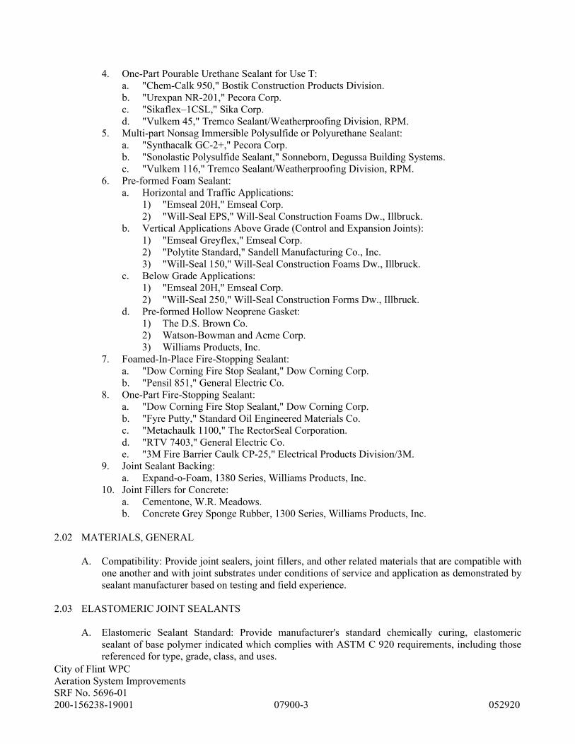
City of Flint WPC
Aeration System Improvements
SRF No. 5696-01
200-156238-19001 07900-3 052920
4. One-Part Pourable Urethane Sealant for Use T:
a. "Chem-Calk 950," Bostik Construction Products Division.
b. "Urexpan NR-201," Pecora Corp.
c. "Sikaflex–1CSL," Sika Corp.
d. "Vulkem 45," Tremco Sealant/Weatherproofing Division, RPM.
5. Multi-part Nonsag Immersible Polysulfide or Polyurethane Sealant:
a. "Synthacalk GC-2+," Pecora Corp.
b. "Sonolastic Polysulfide Sealant," Sonneborn, Degussa Building Systems.
c. "Vulkem 116," Tremco Sealant/Weatherproofing Division, RPM.
6. Pre-formed Foam Sealant:
a. Horizontal and Traffic Applications:
1) "Emseal 20H," Emseal Corp.
2) "Will-Seal EPS," Will-Seal Construction Foams Dw., Illbruck.
b. Vertical Applications Above Grade (Control and Expansion Joints):
1) "Emseal Greyflex," Emseal Corp.
2) "Polytite Standard," Sandell Manufacturing Co., Inc.
3) "Will-Seal 150," Will-Seal Construction Foams Dw., Illbruck.
c. Below Grade Applications:
1) "Emseal 20H," Emseal Corp.
2) "Will-Seal 250," Will-Seal Construction Forms Dw., Illbruck.
d. Pre-formed Hollow Neoprene Gasket:
1) The D.S. Brown Co.
2) Watson-Bowman and Acme Corp.
3) Williams Products, Inc.
7. Foamed-In-Place Fire-Stopping Sealant:
a. "Dow Corning Fire Stop Sealant," Dow Corning Corp.
b. "Pensil 851," General Electric Co.
8. One-Part Fire-Stopping Sealant:
a. "Dow Corning Fire Stop Sealant," Dow Corning Corp.
b. "Fyre Putty," Standard Oil Engineered Materials Co.
c. "Metachaulk 1100," The RectorSeal Corporation.
d. "RTV 7403," General Electric Co.
e. "3M Fire Barrier Caulk CP-25," Electrical Products Division/3M.
9. Joint Sealant Backing:
a. Expand-o-Foam, 1380 Series, Williams Products, Inc.
10. Joint Fillers for Concrete:
a. Cementone, W.R. Meadows.
b. Concrete Grey Sponge Rubber, 1300 Series, Williams Products, Inc.
2.02 MATERIALS, GENERAL
A. Compatibility: Provide joint sealers, joint fillers, and other related materials that are compatible with
one another and with joint substrates under conditions of service and application as demonstrated by
sealant manufacturer based on testing and field experience.
2.03 ELASTOMERIC JOINT SEALANTS
A. Elastomeric Sealant Standard: Provide manufacturer's standard chemically curing, elastomeric
sealant of base polymer indicated which complies with ASTM C 920 requirements, including those
referenced for type, grade, class, and uses.
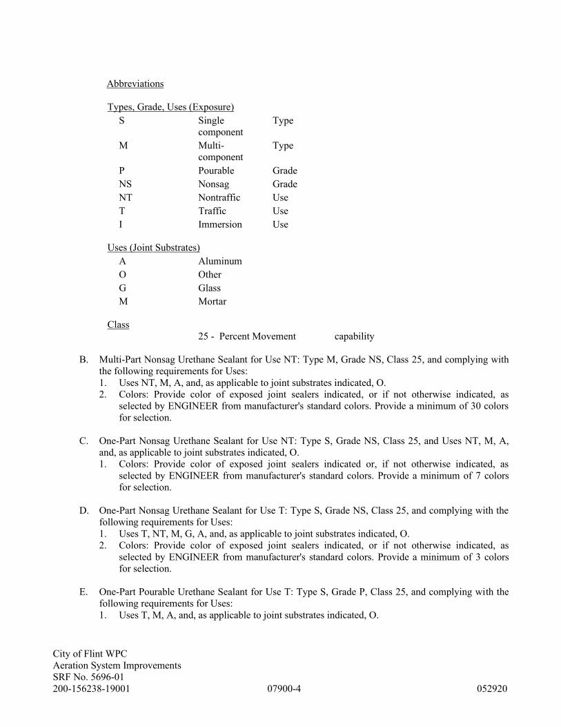
City of Flint WPC
Aeration System Improvements
SRF No. 5696-01
200-156238-19001 07900-4 052920
Abbreviations
Types, Grade, Uses (Exposure)
S Single
component
Type
M Multi-
component
Type
P Pourable Grade
NS Nonsag Grade
NT Nontraffic Use
T Traffic Use
I Immersion Use
Uses (Joint Substrates)
A Aluminum
O Other
G Glass
M Mortar
Class
25 - Percent Movement capability
B. Multi-Part Nonsag Urethane Sealant for Use NT: Type M, Grade NS, Class 25, and complying with
the following requirements for Uses:
1. Uses NT, M, A, and, as applicable to joint substrates indicated, O.
2. Colors: Provide color of exposed joint sealers indicated, or if not otherwise indicated, as
selected by ENGINEER from manufacturer's standard colors. Provide a minimum of 30 colors
for selection.
C. One-Part Nonsag Urethane Sealant for Use NT: Type S, Grade NS, Class 25, and Uses NT, M, A,
and, as applicable to joint substrates indicated, O.
1. Colors: Provide color of exposed joint sealers indicated or, if not otherwise indicated, as
selected by ENGINEER from manufacturer's standard colors. Provide a minimum of 7 colors
for selection.
D. One-Part Nonsag Urethane Sealant for Use T: Type S, Grade NS, Class 25, and complying with the
following requirements for Uses:
1. Uses T, NT, M, G, A, and, as applicable to joint substrates indicated, O.
2. Colors: Provide color of exposed joint sealers indicated, or if not otherwise indicated, as
selected by ENGINEER from manufacturer's standard colors. Provide a minimum of 3 colors
for selection.
E. One-Part Pourable Urethane Sealant for Use T: Type S, Grade P, Class 25, and complying with the
following requirements for Uses:
1. Uses T, M, A, and, as applicable to joint substrates indicated, O.
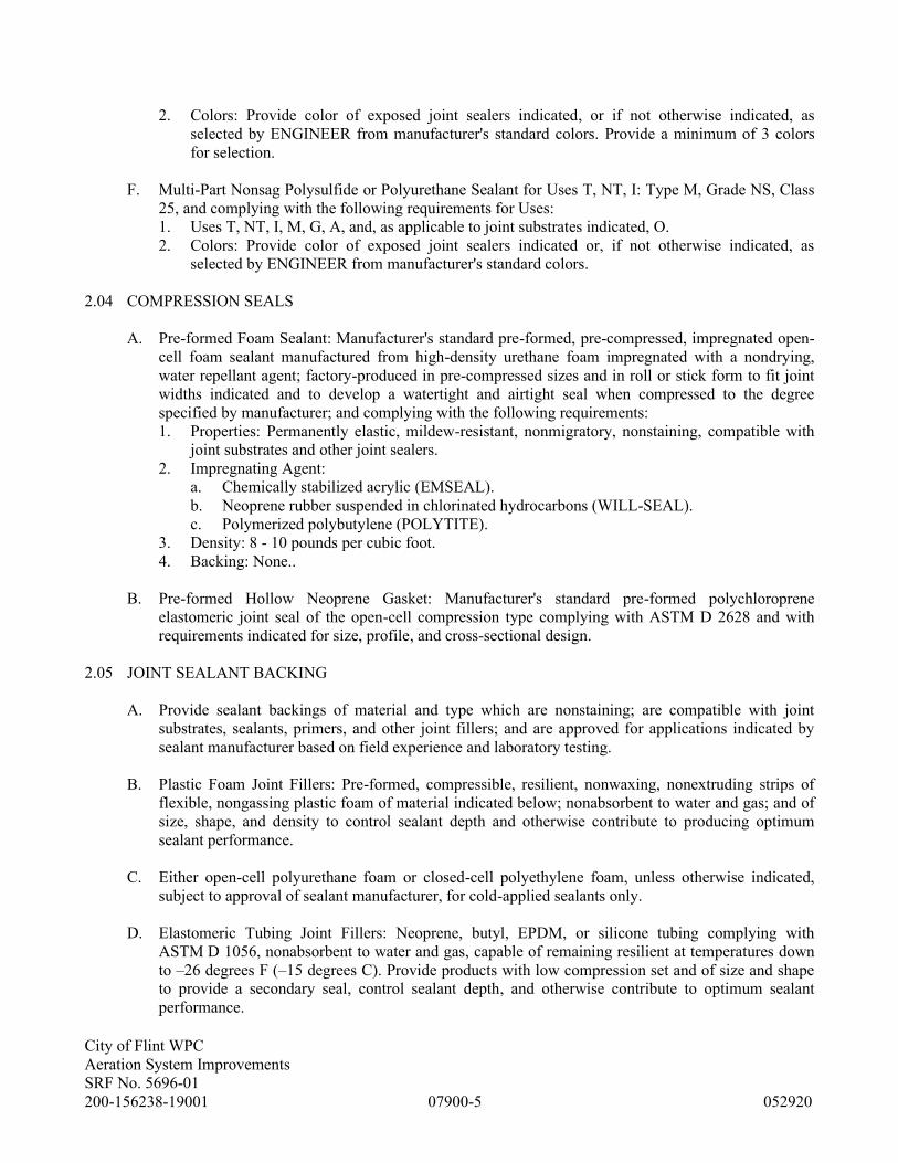
City of Flint WPC
Aeration System Improvements
SRF No. 5696-01
200-156238-19001 07900-5 052920
2. Colors: Provide color of exposed joint sealers indicated, or if not otherwise indicated, as
selected by ENGINEER from manufacturer's standard colors. Provide a minimum of 3 colors
for selection.
F. Multi-Part Nonsag Polysulfide or Polyurethane Sealant for Uses T, NT, I: Type M, Grade NS, Class
25, and complying with the following requirements for Uses:
1. Uses T, NT, I, M, G, A, and, as applicable to joint substrates indicated, O.
2. Colors: Provide color of exposed joint sealers indicated or, if not otherwise indicated, as
selected by ENGINEER from manufacturer's standard colors.
2.04 COMPRESSION SEALS
A. Pre-formed Foam Sealant: Manufacturer's standard pre-formed, pre-compressed, impregnated open-
cell foam sealant manufactured from high-density urethane foam impregnated with a nondrying,
water repellant agent; factory-produced in pre-compressed sizes and in roll or stick form to fit joint
widths indicated and to develop a watertight and airtight seal when compressed to the degree
specified by manufacturer; and complying with the following requirements:
1. Properties: Permanently elastic, mildew-resistant, nonmigratory, nonstaining, compatible with
joint substrates and other joint sealers.
2. Impregnating Agent:
a. Chemically stabilized acrylic (EMSEAL).
b. Neoprene rubber suspended in chlorinated hydrocarbons (WILL-SEAL).
c. Polymerized polybutylene (POLYTITE).
3. Density: 8 - 10 pounds per cubic foot.
4. Backing: None..
B. Pre-formed Hollow Neoprene Gasket: Manufacturer's standard pre-formed polychloroprene
elastomeric joint seal of the open-cell compression type complying with ASTM D 2628 and with
requirements indicated for size, profile, and cross-sectional design.
2.05 JOINT SEALANT BACKING
A. Provide sealant backings of material and type which are nonstaining; are compatible with joint
substrates, sealants, primers, and other joint fillers; and are approved for applications indicated by
sealant manufacturer based on field experience and laboratory testing.
B. Plastic Foam Joint Fillers: Pre-formed, compressible, resilient, nonwaxing, nonextruding strips of
flexible, nongassing plastic foam of material indicated below; nonabsorbent to water and gas; and of
size, shape, and density to control sealant depth and otherwise contribute to producing optimum
sealant performance.
C. Either open-cell polyurethane foam or closed-cell polyethylene foam, unless otherwise indicated,
subject to approval of sealant manufacturer, for cold-applied sealants only.
D. Elastomeric Tubing Joint Fillers: Neoprene, butyl, EPDM, or silicone tubing complying with
ASTM D 1056, nonabsorbent to water and gas, capable of remaining resilient at temperatures down
to –26 degrees F (–15 degrees C). Provide products with low compression set and of size and shape
to provide a secondary seal, control sealant depth, and otherwise contribute to optimum sealant
performance.

City of Flint WPC
Aeration System Improvements
SRF No. 5696-01
200-156238-19001 07900-6 052920
E. Bond Breaker Tape: Polyethylene tape or other plastic tape as recommended by sealant manufacturer
for preventing sealant from adhering to rigid, inflexible joint filler materials or joint surfaces at back
of joint where such adhesion would result in sealant failure. Provide self-adhesive tape where
applicable.
2.06 MISCELLANEOUS MATERIALS
A. Primer: Provide type recommended by joint sealer manufacturer where required for adhesion of
sealant to joint substrates indicated, as determined from pre-construction joint sealer substrate tests
and field tests.
B. Cleaners for Nonporous Surfaces: Provide nonstaining, chemical cleaners of type which are
acceptable to manufacturer of sealants and sealant backing materials, which are not harmful to
substrates and adjacent nonporous materials, do not leave oily residues, or otherwise have a
detrimental effect on sealant adhesion or in-service performance.
C. Masking Tape: Provide nonstaining, nonabsorbent type compatible with joint sealants and to
surfaces adjacent to joints.
2.07 JOINT FILLERS FOR CONCRETE
A. Provide joint fillers of thickness and widths indicated.
Sponge Rubber Joint Filler: Pre-formed strips complying with ASTM D 1752 for Type I.
PART 3 - EXECUTION
3.01 ACCEPTABLE INSTALLERS
A. Installer Qualifications: Engage an installer who has successfully completed, within the last 3 years,
at least 3 joint sealer applications similar in type and size to that of this Project.
3.02 EXAMINATION
A. Examine joints indicated to receive joint sealers, with Installer present, for compliance with
requirements for joint configuration, installation tolerances, and other conditions affecting joint
sealer performance. Do not proceed with installation of joint sealers until unsatisfactory conditions
have been corrected.
3.03 PREPARATION
A. Surface Cleaning of Joints: Clean out joints immediately before installing joint sealers to comply
with recommendations of joint sealer manufacturers and the following requirements:
1. Remove all foreign material from joint substrates which could interfere with adhesion of joint
sealer, including dust, paints (except for permanent, protective coatings tested and approved for
sealant adhesion and compatibility by sealant manufacturer), old joint sealers, oil, grease,
waterproofing, water repellants, water, surface dirt, and frost.
2. Clean concrete, masonry, unglazed surfaces of ceramic tile, and similar porous joint substrate
surfaces by brushing, grinding, blast cleaning, mechanical abrading, or a combination of these

City of Flint WPC
Aeration System Improvements
SRF No. 5696-01
200-156238-19001 07900-7 052920
methods to produce a clean, sound substrate capable of developing optimum bond with joint
sealers. Remove loose particles remaining from cleaning operations by vacuuming or blowing
out joints with oil-free compressed air.
3. Remove laitance and form release agents from concrete.
4. Clean metal, glass, porcelain enamel, glazed surfaces of ceramic tile, and other nonporous
surfaces by chemical cleaners or other means which are not harmful to substrates or leave
residues capable of interfering with adhesion of joint sealers.
B. Joint Priming: Prime joint substrates where indicated or where recommended by joint sealer
manufacturer based on pre-construction joint sealer-substrate tests or prior experience. Apply primer
to comply with joint sealer manufacturer's recommendations. Confine primers to areas of joint sealer
bond; do not allow spillage or migration onto adjoining surfaces.
C. Masking Tape: Use masking tape where required to prevent contact of sealant with adjoining
surfaces which otherwise would be permanently stained or damaged by such contact or by cleaning
methods required to remove sealant smears. Remove tape immediately after tooling without
disturbing joint seal.
3.04 INSTALLATION OF JOINT SEALERS
A. Comply with joint sealer manufacturers' printed installation instructions applicable to products and
applications indicated except where more stringent requirements apply.
B. Elastomeric Sealant Installation Standard: Comply with recommendations of ASTM C 962 for use of
joint sealants as applicable to materials, applications, and conditions indicated.
C. Installation of Sealant Backings: Install sealant backings to comply with the following requirements:
1. Install joint fillers of type indicated to provide support of sealants during application and at
position required to produce the cross-sectional shapes and depths of installed sealants relative
to joint widths which allow optimum sealant movement capability.
a. Do not leave gaps between ends of joint fillers.
b. Do not stretch, twist, puncture, or tear joint fillers.
c. Remove absorbent joint fillers which have become wet prior to sealant application and
replace with dry material.
2. Install bond breaker tape between sealants and joint fillers, compression seals, or back of joints
where adhesion of sealant to surfaces at back of joints would result in sealant failure.
3. Install compressible seals serving as sealant backings to comply with requirements indicated
above for joint fillers.
4. Installation of Sealants: Install sealants by proven techniques that result in sealants directly
contacting and fully wetting joint substrates, completely filling recesses provided for each joint
configuration and providing uniform, cross-sectional shapes and depths relative to joint widths
which allow optimum sealant movement capability.
a. Note: Install all sealant in interior joints after painting of adjoining surfaces have been
performed. Do not paint over sealant joints.
D. Tooling of Nonsag Sealants: Immediately after sealant application and prior to time skinning or
curing begins, tool sealants to form smooth, uniform beads of configuration indicated, to eliminate
air pockets, and to ensure contact and adhesion of sealant with sides of joint. Remove excess sealants
from surfaces adjacent to joint. Do not use tooling agents which discolor sealants or adjacent
surfaces or are not approved by sealant manufacturer.

City of Flint WPC
Aeration System Improvements
SRF No. 5696-01
200-156238-19001 07900-8 052920
1. Provide concave joint configuration per Figure 6A in ASTM C 962 unless otherwise indicated.
2. Provide flush joint configuration per Figure 6B in ASTM C 962 where indicated.
3. Use masking tape to protect adjacent surfaces of recessed tooled joints.
4. Provide recessed joint configuration per Figure 6C in ASTM C 962, of recess depth and at
locations indicated.
E. Installation of Pre-formed Foam Sealants: Install each length of sealant immediately after removing
protective wrappings, taking care not to pull or stretch material, and complying with sealant
manufacturer's directions for installation methods, materials, and tools which produce seal continuity
at ends, turns, and intersections of joints. For applications at low ambient temperatures where
expansion of sealant requires acceleration to produce seal, apply heat to sealant in conformance with
sealant manufacturer's recommendations.
F. Installation of Pre-formed Hollow Neoprene Gaskets: Install gaskets, with minimum number of end
joints, in joint recesses with edges free of spalls and sides straight and parallel, both within
tolerances specified by gasket manufacturer. Apply manufacturer's recommended adhesive to joint
substrates immediately prior to installing gaskets. For straight sections, provide gaskets in
continuous lengths; where changes in direction occur, adhesively splice gaskets together to provide
watertight joint. Recess gasket below adjoining joint surfaces by 1/8 to 1/4 inch.
3.05 CLEANING
A. Clean off excess sealants or sealant smears adjacent to joints as Work progresses, by methods and
with cleaning materials approved by manufacturers of joint sealers and of products in which joints
occur.
3.06 PROTECTION
A. Protect joint sealers during and after curing period from contact with contaminating substances or
from damage resulting from construction operations or other causes so that they are without
deterioration or damage at time of Substantial Completion. If, despite such protection, damage or
deterioration occurs, cut out and remove damaged or deteriorated joint sealers immediately and
reseal joints with new materials to produce joint sealer installations with repaired areas
indistinguishable from original Work.
END OF SECTION
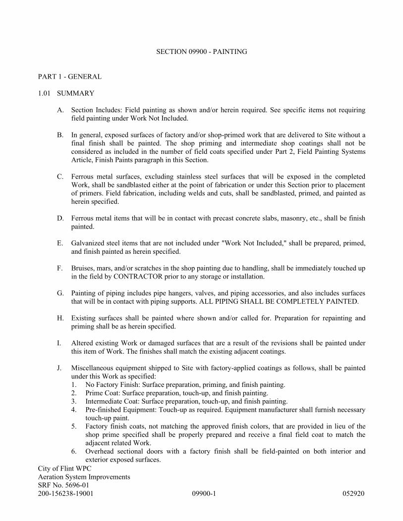
City of Flint WPC
Aeration System Improvements
SRF No. 5696-01
200-156238-19001 09900-1 052920
SECTION 09900 - PAINTING
PART 1 - GENERAL
1.01 SUMMARY
A. Section Includes: Field painting as shown and/or herein required. See specific items not requiring
field painting under Work Not Included.
B. In general, exposed surfaces of factory and/or shop-primed work that are delivered to Site without a
final finish shall be painted. The shop priming and intermediate shop coatings shall not be
considered as included in the number of field coats specified under Part 2, Field Painting Systems
Article, Finish Paints paragraph in this Section.
C. Ferrous metal surfaces, excluding stainless steel surfaces that will be exposed in the completed
Work, shall be sandblasted either at the point of fabrication or under this Section prior to placement
of primers. Field fabrication, including welds and cuts, shall be sandblasted, primed, and painted as
herein specified.
D. Ferrous metal items that will be in contact with precast concrete slabs, masonry, etc., shall be finish
painted.
E. Galvanized steel items that are not included under "Work Not Included," shall be prepared, primed,
and finish painted as herein specified.
F. Bruises, mars, and/or scratches in the shop painting due to handling, shall be immediately touched up
in the field by CONTRACTOR prior to any storage or installation.
G. Painting of piping includes pipe hangers, valves, and piping accessories, and also includes surfaces
that will be in contact with piping supports. ALL PIPING SHALL BE COMPLETELY PAINTED.
H. Existing surfaces shall be painted where shown and/or called for. Preparation for repainting and
priming shall be as herein specified.
I. Altered existing Work or damaged surfaces that are a result of the revisions shall be painted under
this item of Work. The finishes shall match the existing adjacent coatings.
J. Miscellaneous equipment shipped to Site with factory-applied coatings as follows, shall be painted
under this Work as specified:
1. No Factory Finish: Surface preparation, priming, and finish painting.
2. Prime Coat: Surface preparation, touch-up, and finish painting.
3. Intermediate Coat: Surface preparation, touch-up, and finish painting.
4. Pre-finished Equipment: Touch-up as required. Equipment manufacturer shall furnish necessary
touch-up paint.
5. Factory finish coats, not matching the approved finish colors, that are provided in lieu of the
shop prime specified shall be properly prepared and receive a final field coat to match the
adjacent related Work.
6. Overhead sectional doors with a factory finish shall be field-painted on both interior and
exterior exposed surfaces.
City of Flint WPC
Aeration System Improvements
SRF No. 5696-01
200-156238-19001 09900-2 052920
K. Painting as called for on Drawings is for guidance only and does not limit the requirements for
painting.
L. Work Not Included: Unless specifically called for on Drawings or specified in this Section, the
following are not included:
1. Exterior exposed concrete surfaces and exposed concrete surfaces below the ground floor plan.
2. Nonferrous metals and stainless steel, except copper and brass.
3. Exterior aluminum siding.
4. Nonexposed surfaces of treated lumber.
5. Conduits below the main floor, except in rooms that are painted.
6. Exterior gratings with a hot-dipped galvanized finish.
7. Manufacturer's name and identification plates.
8. All interior and exterior sealant and caulking unless adjacent to latex-coated surfaces and
approved by ENGINEER.
1.02 DEFINITIONS
A. Potable Water Use Defined: Paint or coatings in contact with water anywhere within the potable
water system (including intake/treatment/storage/distribution), shall be tested and certified by the
National Sanitation Foundation (NSF) or Underwriter’s Laboratory (UL) as a protective (barrier)
material as per ANSI/NSF Standard 61 (Listed Drinking Water System Components - Health
Effects).
1.03 SUBMITTALS
A. Shop Drawings: Submit in accordance with Section 01330, Shop Drawings covering the items
included under this Section. Shop Drawing submittals shall include:
1. Listing of all materials proposed for use on Work, including designation of the area, primer
required, or purpose.
2. Specification data sheets included for each specific material proposed.
3. Application instructions included for each specific material proposed.
4. Color samples.
B. Furnish ENGINEER, for approval, a schedule for all painting as called for on Painting Schedule and
Piping Color Code and Identification subsection.
C. Warranty: Submit in accordance with requirements of Section 01770, warranties covering the items
included under this Section.
1.04 QUALITY ASSURANCE
A. Single Source Responsibility: Provide primers and undercoat paint produced by the same
manufacturer as the finish coats.
B. CONTRACTOR's Responsibility: It shall be CONTRACTOR's responsibility to check the
compatibility of painting materials proposed for this Contract. CONTRACTOR shall coordinate this
Work with other trades to ensure compliance with these Specifications.
C. Acceptability of materials and performance shall be determined by ENGINEER.

City of Flint WPC
Aeration System Improvements
SRF No. 5696-01
200-156238-19001 09900-3 052920
D. Testing or certification may be required to aid ENGINEER's determination of fitness.
1. Expense of testing and certification when required and, unless noted otherwise in the Contract
Documents, shall be borne by CONTRACTOR.
2. If destructive testing is required, CONTRACTOR shall repair damaged area. Expense of repair
shall be borne by CONTRACTOR.
E. Request, in writing, a review of each coat by ENGINEER of first finished surface of each type of
color, texture, and workmanship. First acceptance of each type and color shall be visibly labeled by
ENGINEER with removable labels as Project standard for that type and color of item. Labels shall
remain in place until Work is finished.
1. For spray application, paint a surface of 100-square-foot as Project standard.
2. For roller application, apply a 36-square-foot mock-up as Project standard.
F. All Work may be inspected as to proper surface preparation, pre-treatment, priming, dry film
thickness, curing, color, and workmanship. CONTRACTOR shall supply the following applicable
standards, test methods, and inspection equipment:
1. SSPC-VIS-1 photographic blast cleaning standards.
2. Inspectors wet film gauge.
3. Inspectors magnetic dry film thickness gauge.
4. Tinkor Razor M-1 low voltage Holiday Detector.
5. Marke 5 Tooke Gauge.
1.05 FIELD PAINTING SUBMITTAL SCHEDULE
A. Furnish ENGINEER, for approval, prior to commencing any painting, a Schedule similar to that
below:

City of Flint WPC
Aeration System Improvements
SRF No. 5696-01
200-156238-19001 09900-4 052920
FIELD PAINTING SUBMITTAL SCHEDULE
Item and/or Location Type Material Coverage per
Coat
Paint Manufacturer
Pre-treatment
Primers
Barrier coats
Sealers
Filler and leveling coats
Existing paint, water-base epoxy coated
Interior concrete floors and walkways,
nonslip epoxy coated
Interior concrete bases, curbs and platforms,
epoxy coated
Interior concrete, epoxy coated
Interior concrete, latex coated
Interior concrete block, epoxy coated
Interior concrete block, latex coated
Exterior concrete block, stained
Exterior concrete block, elastomeric coated
Interior nonsubmerged metal, epoxy coated
Interior nonsubmerged metal, alkyd coated
Exterior nonsubmerged metal, polyurethane
coated
Nonpotable submerged and intermittently
submerged metal, coal-tar epoxy coated
Potable submerged and intermittently
submerged metal, epoxy coated
Interior wood, alkyd coated
Interior wood, stained
Exterior wood, stained
Exterior wood, latex coated
Exterior PVC, vinylester, fiberglass,
polyurethane coated
Interior PVC, vinylester, fiberglass, epoxy
coated
Insulated piping, latex coated
Interior plaster and drywall, latex coated
Interior plaster and drywall, epoxy coated
Exterior plaster, latex coated.

City of Flint WPC
Aeration System Improvements
SRF No. 5696-01
200-156238-19001 09900-5 052920
1.06 PROJECT MEETING
A. Prior to ordering any materials under this Section, CONTRACTOR, ENGINEER, painting
subcontractor, and paint manufacturer's representative shall attend a progress meeting to review
Work to be performed under this Section.
1.07 DELIVERY, STORAGE, AND HANDLING
A. Deliver materials to Site in manufacturer's original, unopened packages and containers, bearing
manufacturer's name and label and the following information:
1. Product name or title of material.
2. Product description (generic classification or binder type).
3. Federal Specification number, if applicable.
4. Manufacturer's stock number and date of manufacture.
5. Contents by volume for pigment and vehicle constituents.
6. Thinning instructions.
7. Application instructions.
8. Color name and number.
B. Store materials not in use in tightly covered containers in a well-ventilated area at a minimum
ambient temperature of 45 degrees F (7 degrees C). Maintain containers used in storage in a clean
condition, free of foreign materials and residue.
1. Protect from freezing. Keep storage area neat and orderly. Remove oily rags and waste daily.
Take necessary measures to ensure that workers and work areas are protected from fire and
health hazards resulting from handling, mixing, and application.
1.08 PROJECT CONDITIONS
A. Apply water-based paints only when the temperature of surfaces to be painted and surrounding air
temperatures are between 50 degrees F (10 degrees C) and 90 degrees F (32 degrees C).
B. Apply solvent-thinned paints only when the temperature of surfaces to be painted and surrounding
air temperatures are between 45 degrees F (7 degrees C) and 95 degrees F (35 degrees C).
C. Do not apply paint in snow, rain, fog, or mist, when the relative humidity exceeds 85 percent, at
temperatures less than 5 degrees F (3 degrees C) above the dew point, or to damp or wet surfaces.
1. Painting may continue during inclement weather if surfaces and areas to be painted are enclosed
and heated within temperature limits specified by the manufacturer during application and
drying periods.
PART 2 - PRODUCTS
2.01 MANUFACTURERS
A. Subject to compliance with specified requirements, manufacturers offering products which may be
incorporated in Work include:
1. Painting Materials:
a. ICI/Devoe Coatings, Louisville, KY.

City of Flint WPC
Aeration System Improvements
SRF No. 5696-01
200-156238-19001 09900-6 052920
b. Carboline Co., St. Louis, MO 63144.
c. PPG Industries, Pittsburgh, PA 15222.
d. Porter International, Louisville, KY 40203.
e. Sherwin-Williams Company, Cleveland, OH 44101.
f. Tnemec, North Kansas City, MO 64141.
2. Dry Film Thickness Gauge:
a. Elcometer.
b. Nordstrom.
2.02 MATERIALS
A. Painting materials shall be those as herein specified under "Field Painting Systems" Article.
B. The specification designations, manufacturers and/or trade names herein are intended to establish a
quality and standard for the materials used.
C. Colors and sheen, where not specified, shall be selected by ENGINEER.
D. Oil, turpentine, and other thinners used in the finishing Work shall meet the requirements of the
latest appropriate ASTM.
2.03 FIELD PAINTING SYSTEMS
A. The following systems may vary from the coverages and mil thickness shown if recommended by
paint manufacturer and approved in writing by ENGINEER. Number of coats shall be as required to
obtain the mil thickness specified.
B. If no pre-treatment is required by paint manufacturer, the surfaces shall be solvent cleaned
(SSPC-SP1); otherwise the surfaces shall be pre-treated as follows:
1. Nonsubmerged Galvanized Metal: Apply 1 brush coat of phosphoric acid.
2. Nonferrous Metals: Apply 1 coat of a 2-component wash primer formulated with a zinc
chromate pigmented polyvinyl butyral resin and phosphoric acid at a minimum of 0.3 dry mils
and maximum of 0.5 dry mils thickness.
C. Field Priming and Sealing:
1. Concrete and Concrete Block Primer and Sealer: Apply 1 coat of an approved material.
2. Metal Primer: Apply 1 coat of a universal rust-inhibitive primer which can be used on both
submerged and nonsubmerged ferrous metal and has the ability to accept alkyds, epoxy, vinyl,
coal tar, chlorinated rubber, emulsion, coal-tar epoxies, epoxy ester, asphalt, and phenolic paints
as finish coats. Apply at the rate of 1.5 dry mils or as recommended by manufacturer.
3. Nonsubmerged Galvanized Metal Primer: If the finish paint required is self-priming, no primer
is required. Otherwise, apply 1 coat of approved galvanized iron primer that will form a
permanent bond coat for the finish coat.
4. Sealant for Bituminous Coated Surfaces: Apply 2.5 dry mils of synthetic alcohol-soluble resin
and titanium pigment, or as recommended by manufacturer in writing and approved by
ENGINEER.
5. Exterior Wood Primer: Apply 2.0 to 3.5 dry mils of an alkyd-linseed oil mildew-resistant film.
6. Interior Wood Primer: Apply 2.0 to 3.5 dry mils of an oil alkyd undercoater to wood that has a
painted finish called for.
City of Flint WPC
Aeration System Improvements
SRF No. 5696-01
200-156238-19001 09900-7 052920
D. Finish Paints:
1. Existing Painted Walls, Water-Base Acrylic Epoxy Coated: Apply 2 coats of a water-base
acrylic epoxy at 2.0 to 2.5 mils per coat.
2. Interior Concrete Floors, Epoxy Coated: Apply 2 coats of a polyamide-cured epoxy resin finish
at 2.0 to 3.0 dry mils minimum per coat. The second coat shall provide a nonslip surface.
3. Interior Concrete, Epoxy Coated: Apply 2 coats of a polyamide-cured epoxy resin finish at 2.5
to 3.5 dry mils minimum per coat.
4. Interior Concrete Curbs and Platforms: Apply 2 coats of a polyamide-cured epoxy resin finish at
2.0 to 3.0 dry mils minimum per coat.
5. Interior Concrete where Hydrostatic Back-pressure is Determined, Latex Coated: Apply 2 coats
of an acrylic latex finish at 2.0 to 3.0 dry mil minimum per coat.
6. Exterior Nonsubmerged Poured Concrete, Modified Epoxy Masonry Texture Coating: Apply
1 coat of a modified epoxy masonry texture coating at coverage of 70 to 90 square feet per
gallon. Backroll to assure proper penetration into concrete.
7. Interior Concrete Block, Latex Coated: Apply an acrylic emulsion sealer or leveler coat and
2 coats of an acrylic latex finish at 2.0 to 3.0 dry mils per coat.
8. Interior Concrete Block, Epoxy Coated: Apply a modified epoxy sealer at the rate of 60 to
80 square feet per gallon, and 2 coats of a polyamide-cured epoxy resin finish at 2.5 to 3.5 dry
mils per coat.
9. Exterior Concrete Block, Elastomeric Coated: See Section 09672.
10. Exterior Concrete Block, Stained: See Section 07145.
11. Interior Nonsubmerged Metal: In rooms and areas that have the walls finished with latex or
alkyd paint, apply 2 coats of a medium to long alkyd resin finish at 2.0 to 3.5 dry mils per coat.
All other items of interior nonsubmerged metal that are specified to be painted shall be finished
by applying 2 coats of a polyamide-cured epoxy resin finish at 2.0 to 3.0 dry mils per coat.
12. Exterior Nonsubmerged Metal, Polyurethane Coated: Apply 2 coats of a polyamide-cured
epoxy resin finish at 2.5 to 3.5 dry mils, and 1 final coat of an aliphatic polyurethane enamel at
2.0 to 3.0 dry mils. The second coat shall have a color close to the final finish.
13. Non-Potable Submerged and Intermittently Submerged Metal, Coal-tar Epoxy Coated: Apply
2 coats of a coal-tar epoxy finish at 8.0 to 10.0 dry mils per coat.
a. Spray application is necessary to obtain required film thickness. Spray application shall be
made in crosshatches to achieve required dry film thickness. Brush or roller application
will require additional coats to obtain the required film thickness at no additional expense
to OWNER. Additional coats to meet the dry film thickness requirements must be applied
within 24 hours of application of first coat of coal-tar epoxy. CONTRACTOR shall
provide adequate protection of adjacent areas to protect against overspray.
14. Potable Submerged and Intermittently Submerged Metal, Epoxy Coated: Apply 2 coats of an
epoxy-polyamide or epoxy-polyamine system as approved by the NSF for potable water service
conforming to AWWA D102 inside System No. 1.
15. Interior Wood, Alkyd Coated: Apply 2 coats of an alkyd resin finish at 2.0 to 3.0 dry mils per
coat.
16. Interior Wood, Stained: Apply 1 coat of pigmented stain and 3 coats of varnish.
17. Exterior Wood, Stained: Apply 2 coats of pigmented stain.
18. Exterior Wood and Interior Fire-Protected Wood Latex Coated: Apply 2 coats of an acrylic
latex finish at 2.0 dry mils minimum.
19. Exterior PVC, Vinylester, or Epoxy Resin Fiberglass: These nonsubmerged materials shall be
painted the same system as for exterior nonsubmerged metal. Submerged and intermittently
submerged materials shall be painted the same system as for submerged and intermittently
submerged metal.

City of Flint WPC
Aeration System Improvements
SRF No. 5696-01
200-156238-19001 09900-8 052920
20. Interior PVC, Vinylester, or Epoxy Resin Fiberglass, Epoxy Coated: Apply 2 coats of a
polyamide-cured epoxy resin finish at 2.0 to 3.0 dry mils per coat.
21. Insulated Piping, Acrylic Coated: Apply 2 coats of an acrylic enamel at 2.0 to 2.5 dry mils per
coat.
22. Interior Plaster and Drywall, Latex Coated: Apply 1 coat of latex primer at 1.5 dry mils
minimum, and 2 coats of an acrylic latex finish at 1.0 to 1.5 dry mils.
23. Interior Plaster and Drywall, Epoxy Coated: Apply 1 coat of latex primer at 1.5 dry mils, and
2 coats of polyamide-cured epoxy finish at 2.0 to 2.5 dry mils per coat.
24. Exterior Plaster, Latex Coated: Apply 1 coat of a modified epoxy masonry texture coating at the
rate of 80-100 square feet per gallon, and 1 coat of an acrylic latex finish at 2.0 to 3.0 dry mils.
2.04 PIPING COLOR CODE AND IDENTIFICATION
A. CONTRACTOR shall furnish ENGINEER for approval, prior to commencing any painting, a
Schedule showing colors and markings proposed.
B. The pipe color code and identification nomenclature shall be as designated on the Piping Color
Schedule. CONTRACTOR shall contact ENGINEER for an approved color and appropriate name if
no designation is Scheduled.
C. Pipe markings and banding shall be placed on exposed pipe by stenciling or other method as
approved by ENGINEER. The markings shall include an appropriate name and direction of flow
arrow. The markings shall be located at intervals not to exceed 15 feet and shall occur at least once
in every room unless otherwise approved by ENGINEER. Letters and arrows shall be white-on-dark
colored surfaces and black-on-light colored surfaces, shall be proportioned to the size of the pipe,
and shall be located in an area that will facilitate readings.
Size of Identification Letters
Outside Diameter of Pipe
or Covering (inches)
Size of Letters
(inches)
3/4 to 1-1/4 1/2
1-1/2 to 2 3/4
2-1/2 to 6 1-1/4
8 to 10 2-1/2
over 10 3-1/2
PART 3 - EXECUTION
3.01 WORKMANSHIP
A. Workmanship shall be of the best grade with materials evenly spread and smoothly flowed on,
without runs or sagging of materials. No adulterations or changes of proportions shall be permitted
unless recommended by manufacturer and approved by ENGINEER. Paint shall be applied in strict
conformity with the manufacturer's directions.

City of Flint WPC
Aeration System Improvements
SRF No. 5696-01
200-156238-19001 09900-9 052920
3.02 EXAMINATION
A. It is the responsibility of the painter to thoroughly inspect all surfaces prior to the commencement of
Work to determine if the Work is ready to be prepared and painted.
B. Report in writing to ENGINEER, all conditions that may potentially affect the application.
C. Do not commence until such defects have been corrected.
D. Start of painting shall be construed as the applicator’s acceptance of surfaces and conditions within a
particular area.
3.03 PREPARATION
A. General Procedures: Remove hardware and hardware accessories, plates, machined surfaces, lighting
fixtures, and similar items in places that are not to be painted, or provide surface-applied protection
prior to surface preparation and painting. Remove these items if necessary for complete painting of
the items and adjacent surfaces. Following completion of painting operations in each space or area,
removed items shall be reinstalled by workers skilled in the trades involved.
1. Clean surfaces before applying paint or surface treatments. Remove oil and grease prior to
cleaning. Schedule cleaning and painting so that dust and other contaminants from the cleaning
process will not fall on wet, newly painted surfaces.
B. Surface Preparation: Prior to applying specific finishes, exposed surfaces requiring field painting
shall be properly filled, scraped, sanded, etched, brushed, and/or cleaned as required to provide
surfaces free from dirt, loose crystals, rust, scale, oil, and grease.
1. Surfaces shall be prepared in accordance with manufacturer's recommendations. Surfaces shall
be inspected and accepted by CONTRACTOR before coatings are applied.
2. No change in treatment of surfaces shall be permitted unless recommended by manufacturer and
approved by ENGINEER.
C. Cementitious Materials Preparation: Prepare concrete, concrete masonry block, cement plaster, and
mineral-fiber-reinforcement panel surfaces to be painted. Remove efflorescence, chalk, dust, dirt,
grease, oils, and release agents. Roughen, as required, to remove glaze. If hardeners or sealers have
been used to improve curing, use mechanical methods of surface preparation.
1. Use abrasive blast-cleaning methods if recommended by the paint manufacturer.
2. Cementitious Work shall be cured at least 28 days before painting.
3. Determine alkalinity and moisture content of surfaces by performing appropriate tests. If
surfaces are sufficiently alkaline to cause the finish paint to blister and burn, correct this
condition before application. Do not paint surfaces where moisture content exceeds that
permitted in manufacturer’s printed directions.
4. Hidden dampness (moisture content) shall be checked by using a polyethylene cover test. A
heavy gauge plastic film, approximately 18 inches square and 4 mils thick, is securely taped to a
small section of the concrete. Pieces of test film should be placed at various locations not
exposed to direct sunlight that are likely to be slow drying, such as below grade, low spots in
floors, inside corners, and lower wall areas. The polyethylene sheet is checked after 24 hours for
beads of moisture. If condensation appears on the back side of the film, or if the concrete under
the film appears to be darker, damp or wet, this indicates the presence of moisture in the
concrete. Painting shall not be performed until no condensation exists after the 24-hour test
period.

City of Flint WPC
Aeration System Improvements
SRF No. 5696-01
200-156238-19001 09900-10 052920
5. Steel troweled surfaces shall be acid etched to a "fine sandpaper" finish with a muriatic solution
of approximately 10 to 15 percent. Flush the floor with clean water to remove acids, neutralize
with ammonia, rinse, allow to dry, and vacuum before painting.
6. Surfaces formed by smooth formwork shall be whipped (brush-off) sandblasted to remove all
slag, laitance, form release agents, rough edges, and open air holes. All bug holes shall be filled
with non-shrink, nonmetallic grout.
D. Metals Preparation: Submerged ferrous metals shall have all welds ground smooth to remove spatter,
recesses, pinholes, and protrusions. Metal shall be degreased in accordance with SSPC-SP1 and
abrasive blast cleaned in accordance with SSPC-SP10, "Near White Abrasive Blast Cleaning."
1. Nonsubmerged ferrous metals shall be degreased in accordance with SSPC-SP1 and sandblasted
in accordance with SSPC-SP6, "Commercial Abrasive Blast Cleaning."
2. Nonferrous and galvanized metals shall be degreased in accordance with SSPC-SP1.
3. Submerged galvanized metals shall not be treated.
4. Steel surfaces that are to be repainted shall be commercial blast cleaned in accordance with
SSPC-SP6 until at least 2/3 of each element is free of all visible residues.
E. Wood Preparation: Wood surfaces to be finished shall be clean, dry, smooth, warm, and in proper
condition to receive the finish. Remove surface deposits of sap or pitch by scraping and wiping clean
with mineral spirits. Spot coat knots, pitch streaks, and sappy sections with sealer. Fill nail holes and
cracks after the primer has dried and sand between coats. Back-prime interior and exterior
woodwork.
F. PVC and FRP Preparation: No special surface treatment is required. Surface shall be clean and dry.
G. Drywall Construction: Joint compound material shall be sanded to provide a smooth flat surface.
Remove dust from surface by wiping with clean rags or other means.
3.04 PRE-TREATMENT OF METAL
A. Nonsubmerged galvanized metal and nonferrous metal shall be pre-treated. The galvanized pre-
treatment shall be allowed 30 minutes for reaction to take place, then the residue shall be removed
with a water rinse.
3.05 FIELD PRIMING AND SEALING
A. In general, metal surfaces requiring field painting shall receive a priming coat before shipment from
the shop. Such priming coats shall be compatible to subsequent applied coats.
1. Wherever Work requiring field painting bears no priming coat, or has a damaged shop coat, it
shall have the surface prepared as specified and shall receive an approved priming coat, applied
before and in addition to the finish coats required.
2. Concrete surfaces, requiring field painting, shall be primed and sealed if recommended by the
manufacturer of the finish paint.
3.06 PAINT MATERIALS PREPARATION
A. Carefully mix and prepare paint materials in accordance with manufacturer's directions.
1. Maintain containers used in mixing and application of paint in a clean condition, free of foreign
materials and residue.

City of Flint WPC
Aeration System Improvements
SRF No. 5696-01
200-156238-19001 09900-11 052920
2. Stir material before application to produce a mixture of uniform density; stir as required during
application. Do not stir surface film into material. Remove film and, if necessary, strain material
before using.
3. Use only thinners approved by paint manufacturer and only within recommended limits.
3.07 TINTING
A. Tint each undercoat a lighter shade to facilitate identification of each coat where multiple coats of
the same material are applied. Tint undercoats to match the color of the finish coat but provide
sufficient differences in shade of undercoats to distinguish each separate coat.
3.08 APPLICATION
A. First Field Coat: The first field coat shall be the best suited for use with the surfaces to be covered
and with the final coats. Whenever the finish color permits, the first coat shall be slightly tinted to
the end that complete coverage of the final coat may be assured.
B. Finish Coats: Apply in a uniform manner and of the mil thicknesses as specified. Where the mil
thickness recommended by manufacturer is in conflict with that thickness specified, the proposed
thickness shall be submitted in writing by manufacturer, supported by evaluative data sheets, subject
to approval by ENGINEER. Where the mil thickness is omitted, it shall be as recommended by the
manufacturer to give an excellent surface finish. Finished surface thickness shall be subject to spot
checking by ENGINEER using a wet and/or dry gauge. Deficiencies in required thickness shall be
corrected by addition of extra coats at no additional cost to OWNER.
C. Thinners: Those recommended by manufacturer shall be used and the amounts shall not exceed
recommendations by manufacturer.
D. Caution: Paints shall not be applied on damp surfaces or on preceding coats not thoroughly dried,
and shall not be applied on outside surfaces in extreme cold, frosty, foggy, or damp weather unless
permitted by the materials manufacturer in the standard application specification. Materials shall not
be applied when the temperature is below 50 degrees F. Drying time between coats shall be as
recommended by paint manufacturer.
E. Spraying: Spraying will be permitted only for such Work as approved by ENGINEER.
1. Spraying equipment shall be of a type and capacity adapted to Work and shall be subject to
ENGINEER's approval. Spraying equipment, including temporary rigid piping, flexible hose,
nozzles, etc., shall be kept in such condition as will ensure against breakdowns and stoppage.
2. Particular care shall be exercised to prevent the soiling or damaging of adjacent Work. Brushing
shall immediately follow the spraying when necessary to eliminate wrinkling, blistering, and air
holes.
F. Painting Existing Surfaces: Repainted existing surfaces shall receive a finish to match the existing
Work. Where the existing surfaces are irregular, they shall be made smooth with an approved leveler
coat.

City of Flint WPC
Aeration System Improvements
SRF No. 5696-01
200-156238-19001 09900-12 052920
3.09 PROTECTION, SPECIAL PRECAUTIONS, AND CLEAN UP
A. Reasonable care shall be used to prevent splattering. Drop cloths and masking materials shall be used
to protect surfaces and parts of equipment that are not required to be painted under the Contract.
Splashes, drippings, and stains shall be thoroughly removed upon the completion of Work.
B. Provide "wet paint" signs to protect newly painted finishes. Remove temporary protective wrappings
provided by others for protection of their Work after completion of painting operations.
1. At completion of construction activities of other trades, touch up and restore damaged or
defaced painted surfaces.
C. Lighting fixtures shall be covered and protected, or removed and replaced upon completion of Work.
Electric switch plates, surface hardware, and similar equipment shall be removed, protected and
replaced.
D. Materials shall be stored and mixed in a well-ventilated location as designated or approved by
ENGINEER. Paints and related materials shall be stored in an area that is protected in accordance
with NFPA Bulletin No. 101. They shall be kept in a neat condition and shall be sealed or covered
when not in use. Empty containers shall not be allowed to accumulate on the premises. Oily waste
rags, etc., shall be collected each day and destroyed or stored in a tightly covered metal container.
E. Comply with manufacturer's recommendations regarding environmental conditions under which
coatings and coat systems can be applied.
F. During surface preparation, CONTRACTOR shall take all precautions necessary to protect related
Work. Equipment items and Work areas shall be tightly covered so as not to be damaged by the
painting operation. Special attention shall be made to protect equipment items during sandblasting
operations.
G. CONTRACTOR shall be responsible for clean up of painting materials upon completion of Work.
H. As soon as painting Work is accepted by CONTRACTOR, it shall become its responsibility for
protection, final cleaning, and touch-up.

City of Flint WPC
Aeration System Improvements
SRF No. 5696-01
200-156238-19001 09900-13 052920
Piping Color Schedule - Wastewater Treatment
Type Base Color Bands*
WATER LINES
Finished or Potable Dark Blue
Service or Nonpotable Light Blue Black
Circulating - Hot and Return Dark Blue Red
Deionized Dark Blue White
Tempered Dark Blue Light Gray
CHEMICAL LINES
Alum Orange
Caustic Yellow Green
Polymer Solution Purple
Chlorine (Gas or Solution) Yellow
Ferric Chloride Solution Orange
Fluorosilicic Acid Light Blue Red
Sulfur Dioxide Yellow Red
WASTE LINES
Raw Sludge Brown Black
Sludge Recirculation Suction Line Brown Yellow
Sludge Draw Off Line Brown Orange
Sludge Recirculation Discharge Line Brown
Sludge Gas Line Red
Sewer (Sanitary, Discharge, or Other) Dark Gray
Final Effluent Light Gray
Supernatant Light Green Dark Green
Scum Light Gold
Drainage and Vent **Black
Mixed Liquor (Combined Flow of Raw or
Settled with Return Sludge)
Light Brown
MISCELLANEOUS ITEMS
Vacuum Black White
Compressed Air Dark Green
Natural Gas Safety Red Black
Fuel Oil/Diesel Safety Red
Steam Supply and Return Safety Red White
Sample Piping To match piping sampled
Electrical Conduit **Light Gray
Pumps, Valves, and Compressors To match piping color of line it serves
Low Pressure Air and Blowers Black Light Gray
* Banding shall be 6 inches wide at 30-inch c/c.
** When exposed to the building interiors above the basement areas, the color shall match the adjacent finish.
END OF SECTION
City of Flint WPC
Aeration System Improvements
SRF No. 5696-01
200-156238-19001 09961-1 052920
SECTION 09961 - HIGH PERFORMANCE COATINGS
PART 1 GENERAL
1.01 REFERENCES
A. The following is a list of standards which may be referenced in this section:
1. American Water Works Association (AWWA):
a. C203, Coal-Tar Protective Coatings and Linings for Steel Water
Pipelines-Enamel and Tape-Hot-Applied.
b. C209, Cold-Applied Tape Coatings for the Exterior of Special
Sections, Connections, and Fittings for Steel Water Pipelines.
c. C213, Fusion-Bonded Epoxy Coating for the Interior and Exterior
of Steel Water Pipelines.
d. C214, Tape Coating Systems for the Exterior of Steel Water
Pipelines.
2. Environmental Protection Agency (EPA).
3. International Concrete Repair Institute (ICRI) Guideline No. 310.2 -
Selecting and Specifying Concrete Surface Preparation for Sealers,
Coatings, and Polymer Overlays.
4. NACE International (NACE): SP0188, Discontinuity (Holiday) Testing
of New Protective Coatings on Conductive Substrates.
5. ANSI / NSF International (NSF): 61, Drinking Water System
Components Health Effects.
6. National Association of Pipe Fabricators (NAPF)
a. 500-03-04, Abrasive Blast Cleaning for Ductile Iron Pipe.
7. Occupational Safety and Health Act (OSHA).
8 The Society for Protective Coatings (SSPC):
a. SSPC-PA 2, Measurement of Dry Coating Thickness with
Magnetic Gages.
b. SSPC-PA 3, Guide to Safety in Paint Applications.
c. SSPC-SP 1, Solvent Cleaning.
d. SSPC-SP 2, Hand Tool Cleaning.
e. SSPC-SP 3, Power Tool Cleaning.
f. SSPC-SP 5/NACE 1, White Metal Blast Cleaning.
g. SSPC-SP 6/NACE 3, Commercial Blast Cleaning.
h. SSPC-SP 7, Joint Surface Preparation Standard Brush-Off Blast
Cleaning.
i. SSPC-SP 10/NACE 2, Near-White Blast Cleaning.
j. SSPC-SP 11, Power Tool Cleaning to Bare Metal.
k. SSPC-SP 12, Surface Preparation and Cleaning of Metals
Waterjetting
Prior to Recoating.
l. SSPC-SP 13/NACE 6, Surface Preparation of Concrete.

City of Flint WPC
Aeration System Improvements
SRF No. 5696-01
200-156238-19001 09961-2 052920
m. SSPC-SP 16, Brush-off Blast cleaning of Coated and Uncoated
Galvanized Steel, Stainless Steels, and Non-Ferrous Metals.
n. Guide 15, Field Methods for Retrieval and Analysis of Soluble
Sa1ts on Steel and Other Nonporous Substrates.
o. SSPC-TU 11, Inspection of Fluorescent Coating Systems.
9. National Fire Protection Association (NFPA).
10. American Society for Testing and Materials (ASTM International).
1.02 SUMMARY
A. Section Includes: Field painting as shown and/or herein required. See specific items
not requiring field painting under Work Not Included.
B. Provide all labor, materials, equipment and services for furnishing and installing the
finishes as indicated on drawings and schedules, and as herein specified.
C. In general, exposed surfaces of factory and/or shop-primed work that are delivered to
Site without a final finish shall be painted. The shop priming and intermediate shop
coatings shall not be considered as included in the number of field coats specified
under Part 2, Field Painting Systems Article, Finish Paints paragraph in this Section.
D. Ferrous metal surfaces, excluding stainless steel surfaces that will be exposed in the
completed Work, shall be sandblasted either at the point of fabrication or under this
Section prior to placement of primers. Field fabrication, including welds and cuts,
shall be sandblasted, primed, and painted as herein specified.
E. Ferrous metal items that will be in contact with precast concrete slabs, masonry, etc.,
shall be finish painted.
F. Galvanized steel items that are not included under "Work Not Included," shall be
prepared, primed, and finish painted as herein specified.
G. Bruises, mars, and/or scratches in the shop painting due to handling, shall be
immediately touched up in the field by Contractor prior to any storage or installation.
H. Work includes field painting of exposed bare and covered pipes and ducts (including
color coding), and of hangers, exposed steel and iron work, and primed metal
surfaces of equipment installed under mechanical and electrical work, except as
otherwise indicated.
I. "Paint" as used herein means all coating systems materials, including primers,
emulsions, enamels, stains, sealers and fillers, and other applied materials whether
used as prime, intermediate or finish coats.

City of Flint WPC
Aeration System Improvements
SRF No. 5696-01
200-156238-19001 09961-3 052920
J. Surfaces to be Painted: Except where natural finish of material is specifically noted
as a surface not to be painted, paint exposed surfaces whether or not colors are
designated in "schedules". Where items or surfaces are not specifically mentioned,
paint the same as similar adjacent materials or areas. If color or finish is not
designated, Architect-Engineer will select these from standard colors or finishes
available.
K. Painting of piping includes pipe hangers, valves, and piping accessories, and also
includes surfaces that will be in contact with piping supports. ALL PIPING SHALL
BE COMPLETELY PAINTED.
L. Existing surfaces shall be painted where shown and/or called for. Preparation for
repainting and priming shall be as herein specified.
M. Altered existing Work or damaged surfaces that are a result of the revisions shall be
painted under this item of Work. The finishes shall match the existing adjacent
coatings.
N. Miscellaneous equipment shipped to Site with factory-applied coatings as follows,
shall be painted under this Work as specified:
1. No Factory Finish: Surface preparation, priming, and finish painting.
2. Prime Coat: Surface preparation, touch-up, and finish painting.
3. Intermediate Coat: Surface preparation, touch-up, and finish painting.
4. Pre-finished Equipment: Touch-up as required. Equipment manufacturer shall
furnish necessary touch-up paint.
5. Factory finish coats, not matching the approved finish colors, that are provided in
lieu of the shop prime specified shall be properly prepared and receive a final
field coat to match the adjacent related Work.
O. Painting as called for on Drawings is for guidance only and does not limit the
requirements for painting.
P. Work Not Included: Unless specifically called for on Drawings or specified in this
Section, the following are not included:
1. Exterior exposed concrete surfaces and exterior exposed concrete surfaces below
the ground floor plan.
2. Nonferrous metals and stainless steel, except copper and brass.
3. Exterior aluminum siding.
4. Nonexposed surfaces of treated lumber.
5. Concealed Surfaces: Unless otherwise indicated, painting is not required on
surfaces such as walls or ceilings in concealed areas and generally inaccessible
areas, furred areas, pipe spaces, and duct shafts.
6. Conduits below the main floor, except in rooms that are painted.
7. Exterior gratings with a hot-dipped galvanized finish.

City of Flint WPC
Aeration System Improvements
SRF No. 5696-01
200-156238-19001 09961-4 052920
8. Manufacturer's name and identification plates, such as Underwriters’
Laboratories and Factory Mutual, or any equipment identification, performance
rating, name or nomenclature plates.
9. Overhead sectional doors - shall have a factory finish on both interior and
exterior exposed surfaces.
10. All interior and exterior sealant and caulking unless adjacent to latex-coated
surfaces and approved by Engineer.
11. Interior concrete surfaces of tanks and basins, immersed and exposed not to be
painted.
12. Operating Parts: Unless otherwise indicated, moving parts of operating units,
mechanical and electrical parts, such as valve and damper operators, linkages,
sensing devices, motors, and fan shafts will not require finish painting.
1.03 DEFINITIONS
A. Terms used in this section:
1. ASTM D 16, unless otherwise specified.
2. Coverage: total-minimum dry film thickness in mils or square feet per
gallon.
3. DFT: Dry Film Thickness – Thickness of a coat of cured paint measured
in mils (1/1000 inch).
4. FRP: Fiberglass Reinforced Plastic.
5. HCl: Hydrochloric Acid.
6. MDFT: Minimum Dry Film Thickness, mils.
7. MDFTPC: Minimum Dry Film Thickness per Coat, mils.
8. Mil: Thousandth of an inch.
9. PDS: Product Data Sheet.
10. PSDS: Paint System Data Sheet.
11. PVC: Polyvinyl Chloride.
12. SFPG: Square Feet per Gallon.
13. SFPGPC: Square Feet per Gallon per Coat.
14. SP: Surface Preparation.
1.04 SUBMITTALS
A. Action Submittals:
1. Shop Drawings: Submit in accordance with Division 1 Submittal
Procedures.
a. Data Sheets:
1) For each product, furnish a Product Data Sheet (PDS), the
manufacturer's technical data sheets, and paint colors
available (where applicable). The PDS form is appended
to the end of this section.
2) For each paint system, furnish a Paint System Data Sheet
(PSDS).
City of Flint WPC
Aeration System Improvements
SRF No. 5696-01
200-156238-19001 09961-5 052920
3) Technical and performance information that demonstrates
compliance with Specification.
4) Furnish copies of paint system submittals to the coating
applicator.
5) Indiscriminate submittal of only manufacturer's literature
is not acceptable.
b. Detailed chemical and gradation analysis for each proposed
abrasive material.
2. Samples:
a. Proposed Abrasive Materials: Minimum 5-pound sample for each
type.
b. Reference Panel:
1) Surface Preparation:
a) Prior to start of surface preparation, furnish a 4-
inch by 4-inch steel panel for each grade of
sandblast specified herein, prepared to specified
requirements.
b) Provide panel representative of the steel used;
prevent deterioration of surface quality.
c) Panel to be reference source for inspection upon
approval by Engineer.
2) Paint:
a) Unless otherwise specified, before painting work is
started, prepare minimum 8-inch by 10-inch
sample with type of paint and application specified
on similar substrate to which paint is to be applied.
b) Furnish additional samples as required until colors,
finishes, and textures are approved.
c) Approved samples to be the quality standard for
final finishes.
B. Informational Submittals:
1. Typewritten schedule of Painting Operations. This schedule shall include for
each surface to be painted, the brand name, generic type, solids by volume,
application method, the coverage and number of coats in order to achieve the
specified dry film thickness, and color charts.
2. Coating manufacturer's Certificate of Compliance, in accordance with
Division 1, Manufacturers' Field Services.
3. Factory Applied Coatings: Manufacturer's certification stating factory
applied coating system meets or exceeds requirements specified.
4. Manufacturer's written verification that submitted material is suitable for the
intended use.
5. If the manufacturer of finish coating differs from that of shop primer, provide
finish coating manufacturer's written confirmation that materials are
compatible.

City of Flint WPC
Aeration System Improvements
SRF No. 5696-01
200-156238-19001 09961-6 052920
6. Manufacturer's written instructions and special details for applying each type
of paint.
C. Warranty:
1. Submit manufacturer’s standard warranty in accordance with
requirements of Division 1, warranties covering the items included under
this Section.
1.05 QUALITY ASSURANCE
A. Applicator Qualifications: Minimum 5 years' experience in application of
specified products.
B. Regulatory Requirements:
1. Meet federal, state, and local requirements limiting the emission of
volatile organic compounds.
2. Perform surface preparation and painting in accordance with
recommendations of the following:
a. Paint manufacturer's instructions.
b. SSPC PA 3, Guide to Safety in Paint Applications.
c. Federal, state, and local agencies having jurisdiction.
C. Mockup:
1. Before proceeding with Work under this section, finish one complete
space or item of each color scheme required showing selected colors,
finish texture, materials, quality of work, and special details.
2. After Engineer approval, sample spaces or items shall serve as a standard
for similar work throughout the Project.
D. Pre-application Meeting:
1. Convene a pre-application meeting two [2] weeks before start of
application of coating systems. Require attendance of parties directly
affecting work of this section, including Contractor, Engineer, applicator,
and manufacturer’s representative. Review the following:
a. Environmental requirements.
b. Protection of surfaces not scheduled to be coated.
c. Surface preparation.
d. Application.
e. Repair.
f. Field quality control.
g. Cleaning.
h. Protection of coating systems.
i. One-year inspection.
j. Coordination with other work.

City of Flint WPC
Aeration System Improvements
SRF No. 5696-01
200-156238-19001 09961-7 052920
E. Single Source Responsibility: Provide primers and other undercoat paint
produced by same manufacturer as finish coats. Use only thinners approved by
paint manufacturer, and use only within recommended limits.
F. Coordination of Work: Review other sections of these Specifications in which
prime paints are to be provided to ensure compatibility of total coatings systems
for various substrates. Upon request from other trades, furnish information or
characteristics of finish materials provided for use, to ensure compatible prime
coats are used.
1.06 DELIVERY, STORAGE, AND HANDLING
A. Shipping:
1. Where precoated items are to be shipped to the Site, protect coating from
damage. Batten coated items to prevent abrasion.
2. Protect shop painted surfaces during shipment and handling by suitable
provisions including padding, blocking, and use of canvas or nylon
slings.
B. Deliver materials to job site in original, new and unopened packages and
containers bearing manufacturer's name and label, and following information:
1. Name or title of material.
2. Fed. Spec. number, if applicable.
3. Manufacturer's stock number, batch number, and date of manufacturer.
4. Manufacturer's name.
5. Contents by volume, for major pigment and vehicle constituents.
6. Thinning instructions.
7. Application instructions.
8. Color name and number.
C. Storage:
1. Store products in a protected area that is heated or cooled to maintain
temperatures within the range recommended by paint manufacturer.
2. Primed surfaces shall not be exposed to weather for more than 2 months
before being topcoated, or less time if recommended by coating
manufacturer.
3. Handling: Protect materials during handling and application to prevent
damage or contamination.
4. Keep storage area neat and orderly. Remove oily rags and waste daily.
Take all precautions to ensure that workmen and work areas are
adequately protected from fire hazards and health hazards resulting from
handling, mixing and application of paints.
1.07 PROJECT CONDITIONS

City of Flint WPC
Aeration System Improvements
SRF No. 5696-01
200-156238-19001 09961-8 052920
A. Environmental Requirements:
1. Do not apply paint in temperatures or moisture conditions outside of
manufacturer's recommended maximum or minimum allowable.
2. Do not perform final abrasive blast cleaning whenever relative humidity
exceeds 85 percent, or whenever surface temperature is less than
5 degrees F above dew point of ambient air.
3. Apply water-base paints only when temperature of surfaces to be painted
and surrounding air temperatures are between 50 degrees F (10 degrees
C) and 90 degrees F (32 degrees C), unless otherwise permitted or
restricted by paint manufacturer's printed instructions.
4. Apply solvent-thinned paints only when temperature of surfaces to be
painted and surrounding air temperatures are between 45 degrees F (7
degrees C) and 95 degrees F (35 degrees C), unless otherwise permitted
or restricted by paint manufacturer's printed instructions.
5. Do not apply paint in snow, rain, fog or mist, or when relative humidity
exceeds 85%, or to damp or wet surfaces, unless otherwise permitted or
restricted by paint manufacturer's printed instructions. Painting may be
continued during inclement weather if areas and surfaces to be painted
are enclosed and heated within temperature limits specified by paint
manufacturer during application and drying periods.
6. Paint only when the surface temperature is at least 5 degrees F above the
dew point, unless otherwise permitted by paint manufacturer’s printed
instructions.
B. Status of Existing Coatings:
1. Perform tests as required to verify condition of existing coatings and
substrate conditions.
PART 2 PRODUCTS
2.01 MANUFACTURERS
A. Nationally recognized manufacturers of paints and protective coatings who are
regularly engaged in the production of such materials for essentially identical
service conditions.
B. Minimum of 5 years' verifiable experience in manufacture of specified product.
C. Each of the following manufacturers is capable of supplying most of the products
specified herein:
1. TNEMEC Company, Inc.
2. The Sherwin-Williams Company (Basis of Design).
3. PPG Industries.
4. Carboline.

City of Flint WPC
Aeration System Improvements
SRF No. 5696-01
200-156238-19001 09961-9 052920
2.02 ABRASIVE MATERIALS
A. Abrasives for blasting shall be sharp, washed, salt free, angular, and free from
feldspar or other constituents that tend to breakdown and remain on the surface.
B. Select abrasive type and size to produce surface profile that meets coating
manufacturer's recommendations for specific primer and coating system to be
applied.
2.03 PAINT MATERIALS
A. General:
1. Manufacturer's highest quality products suitable for intended service.
Materials not displaying manufacturer's identification as a standard,
best-grade product will not be acceptable.
2. Compatibility: Only compatible materials from a single manufacturer
shall be used in the Work. Particular attention shall be directed to
compatibility of primers and finish coats.
3. Thinners, Cleaners, Driers, and Other Additives: As recommended by
coating manufacturer.
4. Color Pigments: Pure, non fading, applicable types to suit substrates and
service indicated.
a. Lead content in pigment, if any, is limited to contain not more than
0.06% lead, as lead metal based on the total non volatile (dry film)
of paint by weight.
B. Products:
Product Definition
Acrylic Latex Single-component, 100% acrylic finish as required
Block Filler Primer-sealer designed for rough masonry surfaces, acrylic
emulsion, cementitious acrylic, or epoxy
Coal-Tar Epoxy Amine, polyamide, or phenolic epoxy type, suitable for
immersion service
Epoxy Filler/Surfacer 100% solids epoxy trowel grade filler and surface,
nonshrinking, suitable for application to concrete and masonry
Epoxy Nonskid (Aggregated) 100% solids two-component catalyzed epoxy aggregated;
aggregate may be packaged separately
Epoxy Primer-
Ferrous Metal
High-build, two-component catalyzed epoxy primer.
Epoxy Primer- Other Epoxy primer, high-build, as recommended by coating
manufacturer for specific galvanized metal, copper, or
nonferrous metal alloy to be coated

City of Flint WPC
Aeration System Improvements
SRF No. 5696-01
200-156238-19001 09961-10 052920
Product Definition
Fusion Bonded Coating 100% solids, thermosetting, fusion bonded, dry powder epoxy,
suitable for the intended service
Fusion Bonded, TFE Lube or
Grease Lube
Tetrafluoroethylene, liquid coating, or open gear grease as
supplied by McMaster-Carr Supply Corporation, Elmhurst, IL;
RL 736 manufactured by Amrep, Inc., Marietta, GA
High Build Epoxy High-build, two-component catalyzed epoxy, capability of 3 to
5 MDFT per coat
Epoxy Novolac 100% solids two-component, highly chemical resistant epoxy
Latex Primer Sealer Waterborne vinyl acrylic primer/sealer for interior gypsum
board and plaster. Capable of providing uniform seal and
suitable for use with specified finish coats.
Gloss Polyurethane - Two-component, aliphatic acrylic based polyurethane; high
gloss finish
Multipolymeric Matrix
Coating
Heat resistant single component inert multipolymeric matrix
coating for high heat applications under insulation.
Water Base Epoxy Two-component, polyamide epoxy emulsion, finish as required.
2.04 MIXING
A. Multiple-Component Coatings:
1. Prepare using each component as packaged by paint manufacturer.
2. No partial batches will be permitted.
3. Do not use multiple-component coatings that have been mixed beyond
their pot life.
4. Furnish small quantity kits for touchup painting and for painting other
small areas.
5. Mix only components specified and furnished by paint manufacturer.
6. Do not intermix additional components for reasons of color or otherwise,
even within the same generic type of coating.
B. Maintain containers used in mixing and application of paint in a clean condition,
free of foreign materials and residue.
C. Stir materials before application to produce a mixture of uniform density, and stir
as required during application. Do not stir surface film into material. Remove
film and, if necessary, strain material before using.
1. Colors: Formulate paints with colorants for reasons of color or other
materials that might be affected by presence of hydrogen sulfide or other
gas likely to be present at Site.

City of Flint WPC
Aeration System Improvements
SRF No. 5696-01
200-156238-19001 09961-11 052920
PART 3 - EXECUTION
3.01 GENERAL
A. Provide Engineer minimum 7 days' advance notice to start of field surface
preparation work and coating application work.
B. Perform the Work only in presence of Engineer or their representative, unless
Engineer grants prior approval to perform the Work in Engineer's absence.
C. Schedule inspection of cleaned surfaces and all coats prior to succeeding coat in
advance with Engineer.
D. Protection: Protect work of other trades, whether to be painted or not, against
damage by painting and finishing work. Correct any damage by cleaning,
repairing or replacing, and repainting, as acceptable to Architect-Architect-
Engineer. Provide "Wet Paint" signs as required to protect newly painted
finishes. Remove temporary protective wrappings provided by others for
protection of their work, after completion of painting operations. At completion
of work of other trades, touch up and restore all damaged or defaced painted
surfaces.
3.02 EXAMINATION
A. Factory Finished Items:
1. Scheduling Inspection with Engineer before repairing damaged factory
finished items delivered to Site.
2. Repair abraded or otherwise damaged areas on factory-finished items as
recommended by coating manufacturer. Carefully blend repaired areas
into original finish. If required to match colors, provide full finish coat in
field.
B. Surface Preparation Verification: Inspect and provide substrate surfaces
prepared in accordance with these Specifications and printed directions and
recommendations of paint manufacturer whose product is to be applied. The
more stringent requirements shall apply.
C. Starting of painting work will be construed as acceptance of surfaces and
conditions within any particular area.
D. Do not paint over dirt, rust, scale, grease, moisture, scuffed surfaces, or
conditions otherwise detrimental to formation of a durable paint film.

City of Flint WPC
Aeration System Improvements
SRF No. 5696-01
200-156238-19001 09961-12 052920
3.03 PROTECTION OF ITEMS NOT TO BE PAINTED
A. Remove, mask, or otherwise protect hardware, lighting fixtures, switchplates,
aluminum surfaces, machined surfaces, couplings, shafts, bearings, nameplates
on machinery, and other surfaces not specified elsewhere to be painted.
B. Provide drop cloths to prevent paint materials from falling on or marring
adjacent surfaces.
C. Protect working parts of mechanical and electrical equipment from damage
during surface preparation and painting process.
D. Mask openings in motors to prevent paint and other materials from entering.
E. Protect surfaces adjacent to or downwind of Work area from overspray.
3.04 SURFACE PREPARATION
A. General: Perform preparation and cleaning procedures in accordance with paint
manufacturer's instructions and as herein specified, for each particular substrate
condition, or as required by this specification, the more stringent requirements
shall apply.
1. Provide barrier coats over incompatible primers or remove and re-prime
as required. Notify Architect-Architect-Engineer in writing of any
anticipated problems in using the specified coating systems with
substrates primed by others.
2. Remove hardware, hardware accessories, machined surfaces, plates,
lighting fixtures, and similar items in place and not to be finish-painted,
or provide surface-applied protection prior to surface preparation and
painting operations. Remove, if necessary, for complete painting of
items and adjacent surfaces. Following completion of painting of each
space or area, reinstall removed items.
3. Clean surfaces to be painted before applying paint or surface treatments.
Remove oil and grease prior to mechanical cleaning per SSPC SP-1.
Program cleaning and painting so that contaminants from cleaning
process will not fall onto wet, newly-painted surfaces.
4. Abrasives for blasting shall be sharp, washed, salt free, angular, and free
from feldspar or other constituents that tend to breakdown and remain on
the surface.
5. Concrete floors shall be dry as indicated by testing in accordance with
ASTM D4263, Standard Test Method for Indicating Moisture in Concrete
by the Plastic Sheet Method.
City of Flint WPC
Aeration System Improvements
SRF No. 5696-01
200-156238-19001 09961-13 052920
B. Field Abrasive Blasting:
1. Perform blasting for items and equipment where specified and as required
to restore damaged surfaces previously shop or field blasted and primed
or coated.
2. Refer to coating systems for degree of abrasive blasting required.
3. Where the specified degree of surface preparation differs from
manufacturer's recommendations, the more stringent shall apply.
3.05 SURFACE CLEANING
A. Brush-off Blast Cleaning:
1. Equipment, procedure, and degree of cleaning shall meet requirements of
SSPC SP 7.
2. Abrasive: Either wet or dry blasting sand, grit, or nutshell.
3. Select various surface preparation parameters, such as size and hardness
of abrasive, nozzle size, air pressure, and nozzle distance from surface
such that surface is cleaned without pitting, chipping, or other damage.
4. Verify parameter selection by blast cleaning a trial area that will not be
exposed to view.
5. Engineer will review acceptable trial blast cleaned area and use area as a
representative sample of surface preparation.
6. Repair or replace surface damaged by blast cleaning.
B. Solvent Cleaning:
1. Consists of removal of foreign matter such as oil, grease, soil, drawing
and cutting compounds, and any other surface contaminants by using
solvents, emulsions, cleaning compounds, steam cleaning, or similar
materials and methods that involve a solvent or cleaning action.
2. Meet requirements of SSPC SP 1.
3.06 APPLICATION
A. General:
1. The intention of these Specifications is for existing and new interior
masonry, interior and exterior wood, and metal and submerged metal
surfaces to be painted, whether specifically mentioned or not, except as
specified otherwise. Do not paint exterior concrete surfaces, unless
specifically indicated.
2. Extent of Coating (Immersion): Coatings shall be applied to internal
vessel and pipe surfaces, nozzle bores, flange gasket sealing surfaces,
carbon steel internals, and stainless steel internals, unless otherwise
specified.
3. For coatings subject to immersion, obtain full cure for completed system.
Consult coatings manufacturer's written instructions for these
requirements. Do not immerse coating until completion of curing cycle.

City of Flint WPC
Aeration System Improvements
SRF No. 5696-01
200-156238-19001 09961-14 052920
4. Apply coatings in accordance with these Specifications and paint
manufacturers' printed recommendations and special details. The more
stringent requirements shall apply. Allow sufficient time between coats to
assure thorough drying of previously applied paint.
5. Vacuum clean surfaces free of loose particles. Use tack cloth just prior to
applying next coat.
6. Coat units or surfaces to be bolted together or joined closely to structures
or to one another prior to assembly or installation.
7. Keep paint materials sealed when not in use.
8. Where more than one coat is applied within a given system, alternate
colors to provide a visual reference showing required number of coats
have been applied.
9. Paint surfaces behind movable equipment and furniture same as similar
exposed surfaces. Paint surfaces behind permanently fixed equipment or
furniture with prime coat only before final installation of equipment.
10. Provide finish coats which are compatible with prime paints used.
11. Apply additional coats when undercoats, stains or other conditions show
through final coat of paint, until paint film is of uniform finish, color and
appearance. Give special attention to insure that surfaces, including
edges, corners, crevices, welds, and exposed fasteners receive a dry film
thickness equivalent to that of flat surfaces.
12. Pigmented (Opaque) Finishes: Completely cover to provide an opaque,
smooth surface of uniform finish, color, appearance and coverage.
Cloudiness, spotting, holidays, laps, brush marks, runs, sags, ropiness or
other surface imperfections will not be acceptable. Holiday test coated
steel in immersion areas in accordance with NACE International RP
0188-90.
13. Transparent (Clear) Finishes: Use multiple coats to produce glass smooth
surface film of even luster. Provide a finish free of laps, cloudiness, color
irregularity, runs, brush marks, orange peel, nail holes, or other surface
imperfections. Provide satin finish for final coats, unless otherwise
indicated.
14. Completed Work: Match approved samples for color, texture and
coverage. Remove, refinish or repaint work not in compliance with
specified requirements.
B. Porous Surfaces, Such As Concrete and Masonry:
1. Filler/Surfacer: Use coating manufacturer's recommended product to fill
air holes, bug holes, and other surface voids or defects.
2. Prime Coat: May be thinned to provide maximum penetration and
adhesion.
a. Type and Amount of Thinning: Determined by paint manufacturer
and dependent on surface density and type of coating.

City of Flint WPC
Aeration System Improvements
SRF No. 5696-01
200-156238-19001 09961-15 052920
3. Surface Specified to Receive Water Base Coating: Damp, but free of
running water, just prior to application of coating.
C. Film Thickness and Coverage:
1. Number of Coats:
a. Minimum required without regard to coating thickness.
b. Additional coats may be required to obtain minimum required
paint thickness, depending on method of application, differences
in manufacturers' products, and atmospheric conditions.
2. Application Thickness:
a. Do not exceed coating manufacturer's recommendations.
b. Measure using a wet film thickness gauge to ensure proper
coating thickness during application.
3. Film Thickness Measurements and Electrical Inspection of Coated
Surfaces:
a. Perform with properly calibrated instruments.
b. Recoat and repair as necessary for compliance with Specification.
c. Coats are subject to inspection by Engineer and coating
manufacturer's representative.
4. Visually inspect concrete, masonry, nonferrous metal, plastic, and wood
surfaces to ensure proper and complete coverage has been attained.
5. Give particular attention to edges, angles, flanges, and other similar areas,
where insufficient film thicknesses are likely to be present, and ensure
proper millage in these areas.
6. Apply additional coats as required to achieve complete hiding of
underlying coats. Hiding shall be so complete that additional coats would
not increase the hiding.
3.07 PROTECTIVE COATINGS SYSTEMS AND APPLICATION SCHEDULE
A. Unless otherwise shown or specified, paint surfaces in accordance with the
following application schedule. In the event of discrepancies or omissions in the
following, request clarification from Engineer before starting work in question.
B. The Finish Schedule on Architectural Drawings addresses walls, floors and
ceilings for various buildings Additional requirements are included in the
following schedule which addresses structural steel, prefabricated steel trusses,
process equipment, pumps, piping and other items.
C. NSF International approval required for coatings used in contact with the water
treatment plant process water.
D. System No. 1 Chemical Resistant Concrete Floor / Secondary Containment
(hazardous chemical exposure)

City of Flint WPC
Aeration System Improvements
SRF No. 5696-01
200-156238-19001 09961-16 052920
Surface Prep Paint Material Min. Coats, Cover
SSPC-SP 13/NACE 6 to
achieve ICRI CSP as
required by manufacturer
Urethane Cement
Vapor Barrier /
Surfacer
Manufacturer
Recommended Primer –
4.0 to 6.0 mils DFT
2 coats – 15.0 – 20.0 mils
DFT
Verify resistance to stored commodities and anticipated traffic load PRIOR to
installation.
3.08 FIELD QUALITY CONTROL
A. Testing Equipment:
1. Provide magnetic type dry film thickness gauge to test coating thickness
specified in mils, as manufactured by Nordson Corp., Anaheim, CA,
Mikrotest.
2. Provide low-voltage wet sponge electrical holiday detector to test
completed coating systems, 20 mils dry film thickness or less, except
zinc primer, high-build elastomeric coatings, and galvanizing, for
pinholes, holidays, and discontinuities, as manufactured by Tinker and
Rasor, San Gabriel, CA, Model M-1.
3. Provide high-voltage spark tester to test completed coating systems in
excess of 20 mils dry film thickness. Unit as recommended by coating
manufacturer.
B. Inspection: Leave staging and lighting in place until Engineer has inspected
surface or coating. Replace staging removed prior to approval by Engineer.
Provide additional staging and lighting as requested by Engineer.
C. Unsatisfactory Application:
1. If item has an improper finish color or insufficient film thickness, clean
surface and topcoat with specified paint material to obtain specified color
and coverage. Obtain specific surface preparation information from
coating manufacturer.
2. Evidence of runs, bridges, shiners, laps, or other imperfections is cause
for rejection.
3. Repair defects in accordance with written recommendations of coating
manufacturer.
D. Damaged Coatings, Pinholes, and Holidays:
1. Feather edges and repair in accordance with recommendations of paint
manufacturer.
2. Hand or power sand visible areas of chipped, peeled, or abraded paint,
and feather the edges. Follow with primer and finish coat. Depending on
extent of repair and appearance, a finish sanding and topcoat may be
required.

City of Flint WPC
Aeration System Improvements
SRF No. 5696-01
200-156238-19001 09961-17 052920
3. Apply finish coats, including touchup and damage-repair coats in a
manner that will present a uniform texture and color-matched appearance.
E. The right is reserved by Owner to invoke the following material testing
procedure at any time, and any number of times during period of field painting:
1. Engage services of an independent testing laboratory to sample paint
being used. Samples of materials delivered to project site will be taken,
identified and sealed, and certified in presence of Contractor.
2. Testing laboratory will perform appropriate tests for any or all of
following characteristics: Abrasion resistance, apparent reflectivity,
flexibility, washability, absorption, accelerated weathering, dry opacity,
accelerated yellowness, recoating, skinning, color retention, alkali
resistance and quantitative materials analysis.
F. If test results show that material being used does not comply with specified
requirements, Contractor may be directed to stop painting work, and remove
non-complying paint; pay for testing; repaint surfaces coated with rejected paint;
remove rejected paint from previously painted surfaces if, upon repainting with
specified paint, the two coatings are non-compatible.
3.09 MANUFACTURER'S SERVICES
A. In accordance with Division 1, Manufacturers' Field Services, coating
manufacturer's representative shall be present at Site as follows:
1. On first day of application of any coating system.
2. A minimum of two additional Site inspection visits, each for a minimum
of 4 hours, in order to provide Manufacturer's Certificate of Proper
Installation.
3. As required to resolve field problems attributable to or associated with
manufacturer's product.
4. To verify full cure of coating prior to coated surfaces being places into
immersion service.
a. Inspection Reports: Submit written reports to Engineer and
Contractor describing inspections made and actions taken to
correct nonconforming work. Report nonconforming work not
corrected.
b. Manufacturer’s Field Services: Manufacturer’s representative shall
provide technical assistance and guidance for surface preparation
and application of coating systems.
3.10 CLEANUP
A. Place cloths and waste that might constitute a fire hazard in closed metal
containers or destroy at end of each day.
City of Flint WPC
Aeration System Improvements
SRF No. 5696-01
200-156238-19001 09961-18 052920
B. Upon completion of the Work, remove staging, scaffolding, and containers from
Site or destroy in a legal manner.
C. Remove paint spots, oil, or stains upon adjacent surfaces and floors and leave
entire job clean.
D. As soon as painting Work is accepted by Contactor, it shall become its
responsibility for protection, final cleaning, and tough-up. Recoat entire surface
where touch-up result is visibly different, either in sheen, texture, or color.
Repair coating defects in accordance with manufacturer’s written instructions.
E. Upon completion of painting work, clean window glass and other paint spattered
surfaces. Remove spattered paint by proper methods of washing and scraping,
using care not to scratch or otherwise damage finished surfaces.
3.11 ONE-YEAR INSPECTION
A. Owner will set date for one-year inspection of coating systems.
B. Inspection shall be attended by Owner, Contractor, Engineer, and manufacturer’s
representative.
C. Repair deficiencies in coating systems as determined by Engineer in accordance
with manufacturer’s instructions.
END OF SECTION

City of Flint WPC
Aeration System Improvements
SRF No. 5696-01
200-156238-19001 11285-1 052920
SECTION 11285 - HYDRAULIC GATES
PART 1 - GENERAL
1.01 SUMMARY
A. Section Includes: Labor, materials, and equipment necessary for furnishing the fabrication,
production, installation, or erection of the items specified in this Section as shown on Drawings or
listed on Schedule.
B. Products Furnished But Not Installed Under This Section: Wiring to motor operators and limit
switches shall be done under Division 16.
C. Items furnished under this Section shall be erected under Section 15100. Mechanical joint gaskets for
gates shall be furnished and installed under Section 15100.
D. Anchor bolts shall be installed Division 3 in accordance with certified prints furnished by equipment
manufacturer.
E. Related Sections: Drawings and general provisions of the Contract, including General and
Supplemental Conditions and Division 1 Specification Sections, including Section 01600, apply to
Work of this Section.
1.02 REFERENCES
A. ASTM References:
1. A 126 Gray Iron Castings for Valves, Flanges, and Pipe Fittings.
2. A 276 Stainless Steel Bars and Shapes.
3. A 304 Carbon and Alloy Steel Bars Subject to End-Quench Hardenability Requirements.
4. A 582 Free-Machining Stainless Steel Bars.
5. B 21 Navel Brass Rod, Bar, and Shapes.
6. B 98 Copper-Silicon Alloy Rod, Bar, and Shapes.
7. B 209 Aluminum and Aluminum-Alloy Sheet and Plate.
8. B 308 Aluminum-Alloy 6061-T6 Standard Structural Shapes, Rolled or Extruded.
9. B 584 Copper Alloy Sand Castings for General Applications.
B. ANSI References:
1. B 16.1 Cast Iron Pipe Flanges and Flanged Fittings.
C. AWWA References:
1. AWWA/ANSI C501 Sluice Gates.
1.03 SUBMITTALS
A. Shop Drawings: Submit in accordance with Section 01330, Shop Drawings covering the items
included under this Section. Shop Drawing submittals shall include:
1. Each gate, including accessories, shall be identified on Shop Drawings by its respective mark as
noted on Gate Schedule.

City of Flint WPC
Aeration System Improvements
SRF No. 5696-01
200-156238-19001 11285-2 052920
B. Operation and Maintenance Manuals: Submit in accordance with requirements of Section 01600,
operation and maintenance manuals for items included under this Section.
C. Warranty: Submit in accordance with Section 01770, warranties covering the items included under
this Section.
PART 2 - PRODUCTS
2.01 MANUFACTURERS
A. Subject to compliance with the specified requirements, manufacturers offering products which may
be included in Work include:
1. Rectangular Butterfly Valve or Gate (RB)
a. Henry Pratt
b. Hydrogate
2. Sluice Gates:
a. Hydro Gate.
b. Rodney Hunt.
c. Waterman.
3. Fabricated Stainless Steel Slide Gates:
a. Hydro Gate.
b. Rodney Hunt.
c. Waterman.
d. Whipps Inc.
4. Electric Motor Open-Shut Service Operators:
a. Rotork.
5. Electric Motor Operators for Throttling Service:
a. Rotork.
2.02 COMPONENTS
A. Rectangular Butterfly Valves (RB):
1. Rectangular butterfly valves shall be resilient seated and shall be bubble tight at rated pressures
with flow in either direction.
2. Valve design shall be rated for 10 psi working pressure and 15 psi test pressure. They shall be
satisfactory for applications involving throttling service through the entire range of flow – open to
closed. Valves shall withstand frequent operations and for applications involving valve operation
after long periods of inactivity.
3. Valve discs shall rotate 90 degrees from the full open position to the tight shut position.
4. When subjected to the maximum design head, a stress safety factor of 3.0 on the yield point or 5.0
on ultimate strength, whichever is lower, shall not be exceeded.
5. Valve Bodies: The valve body shall be fabricated of ASTM A36 carbon steel. Upper trunnion shall
be recessed bored for Chevron packing.
6. Valve Disc:
a. The valve disc shall be fabricated of ASTM A36 carbon steel.
b. Seating edge shall be Type 316 stainless steel and shall be ground, polished and contoured.
c. Disc shall be streamlined in shape to prevent turbulence in the full open position and to
minimize pressure drop across valve.
City of Flint WPC
Aeration System Improvements
SRF No. 5696-01
200-156238-19001 11285-3 052920
7. Valve Seat:
a. The resilient valve seat shall be contained in the body of the valve. A seating face shall be
furnished around the periphery of the disc.
b. Resilient valve seats shall be resilient natural rubber or synthetic rubber Buna N. Seating
face shall be type 316 stainless steel.
c. Retaining screws shall be of Type 316 stainless steel.
d. Seat adjustment possible and inherent in the design shall not be less than 1/8 inch and be
fully field adjustable and replaceable without dismantling operator, disc or shaft. No
special tools shall be required for this operation.
8. Valve Shafts:
a. Valve shafts shall be the stub type with shafts extending into the disc for a minimum distance
of at least 1.5 shaft diameters.
b. Shafts shall be securely locked to the disc by Type 316 stainless steel taper pins.
c. A shaft seal shall be provided where the valve shaft projects through the body for the actuator
connection. The seal shall be of a type utilizing a stuffing box and packing gland, so that the
packing can be adjusted or completely replaced without disturbing any part of the valve or
actuator assembly. Packing shall be of the graphite impregnated, lattice braid square type, as
approved by the Engineer.
9. Valve Bearings:
a. Main shaft bearings shall be self-lubricated sleeve type fitted into each valve body trunnion
bore. Unit bearing stress shall not exceed 4000 psi.
b. Each valve assembly shall be furnished with a two-way thrust bearing assembly designed to
hold the disc centered in the valve seat at all times.
c. Thrust bearing shall be secured by locking device and easily accessible for field adjustment
from operator end of the valve.
10. Valve Operators: Valve operators shall be motor actuated with manual over-ride as specified in
this Section of the Work.
B. Sluice Gates (S):
1. Sluice gates shall meet the requirements of AWWA C501 and be furnished complete including
gate, thimble, rubber gasket, mounting hardware, anchor bolts, and appurtenances as listed on
Schedule or shown on Drawings.
2. Sluice gates shall be furnished with ASTM A 126, Class B, cast iron items, seating faces made
of strips of ASTM B 21, Alloy A or B, extruded bronze, wedges, thrust nut, lift nut, or stem
block, and stem couplings shall be ASTM B 584, Alloy 8A or B 584, Alloy B bronze.
Assembly bolts, unless otherwise noted, shall be bronze per ASTM B 98 Alloy A, B, or D.
Studs, nuts, anchor bolts, and stems shall be ASTM A 276,304, or ASTM A 582-303 stainless
steel. Holes shall be made by drilling.
3. Sluice gate reinforcing ribs shall be designed to uniformly distribute wedge pressure and shall
consist of a horizontal rib terminating at each wedge or heavy vertical ribs located along each
side of the gate.
4. The seating face shall be mounted in full width dovetail slots and held in position without use of
screws or other fasteners. After mounting, the seating faces shall be machined to a plane with a
32 micro-inch finish, or better. When the slide is in the fully closed position and wedged into
position against the frame, the maximum clearance between seating faces shall not exceed 0.004
inch.
5. The side wedges shall be a tongue and groove type assembly, solid cast bronze, and keyed to
the cast iron pads to maintain true alignment by preventing undesirable rotation or lateral
movement. The wedge shall be attached to the slide by means of a bronze stud, hex nut, and
washer. Top and bottom wedges shall be solid cast bronze, nonrotating, adjustable with a

City of Flint WPC
Aeration System Improvements
SRF No. 5696-01
200-156238-19001 11285-4 052920
locking device, and attached to the frame with two stainless steel fasteners. Mating and contact
faces on wedging devices shall be fully machined. Wedges shall be located at corners and at
disc stiffeners as required. Top and bottom wedges are not required on gates below 8 feet
unseating head.
6. Normally, Type "F" wall thimble shall be furnished for mounting sluice gates. Type "E" wall
thimbles shall be furnished if recommended by the manufacturer for high unseating pressures.
Special wall thimbles shall be furnished if noted on Schedule. A center ring water stop shall be
around the periphery of the thimble. The front face of the thimble shall be machined, and holes
drilled and tapped to attach the gate. Cored holes will be allowed only if specifically shown on
Drawings.
7. Stem sizing must be designed to accept the maximum thrust of the operator based on 100 foot-
pounds being applied to the operator. Stem size in conjunction with bronze bushed stem guides
shall limit the L/r ratio to 200 maximum. Stems of more than one section shall be jointed by
bronze or stainless steel, couplings threaded and keyed to the stems. The contact surface of the
stem threads shall be machined to a plane with a minimum 32 micro-inch finish or better.
8. Operators shall be as specified herein and shown on Schedule.
2.03 ACCESSORIES
A. Operators:
1. Operators shall be designed with a safety factor of 5 for torsional and shear stresses. The
operating mechanism shall be so located and so designed that parts subject to maintenance shall
be easily accessible.
2. Manual operators shall be so sized that a maximum of 80 pounds of rim force per pull is
required for operation.
3. Positions of operators shall be approved by ENGINEER.
4. Gate shall be made to open when turned to the left or counterclockwise.
5. The direction of the operator to open position shall be indicated on the operator.
6. Bevel Gear: Bevel gear activators shall provide vertical mounting of the handwheel.
Handwheels shall be included.
7. Crank/Handle: Cranks shall be cast iron with a rotating brass grip. They shall be a maximum of
15 inches in length and keyed to the operator nut.
8. Chainwheel: Chainwheels shall be cast iron and furnished complete with chain and guides.
Chain shall be galvanized and shall be looped to extend to within 4 feet of the floor below the
valve.
9. Handwheel: Handwheels shall be fabricated steel. They shall be a maximum of 30 inches in
diameter and keyed to the operating nut.
10. Wrench Head: Wrench heads shall be cast iron with set screw. They shall be furnished for
wrench nuts except where extension stems or T-handle wrenches are required.
11. Wrench Nut: Wrench nuts shall be provided with a 2-inch operating nut when a T-handle
wrench or extension stem is required. Other wrench nuts shall be furnished with a wrench head.
B. Motor Operators:
1. Electric Motor Open-Close Service:
a. Electric motor operators for open-shut service shall meet the requirements of
AWWA C501 Motor-Operated Lift Mechanisms except as hereinafter specified.
b. Controls shall be either "integrally mounted" or separated in a "wall-mounted" enclosure.
The type to be supplied will be designated on Schedule. Deviations from Schedule will not
be accepted.
City of Flint WPC
Aeration System Improvements
SRF No. 5696-01
200-156238-19001 11285-5 052920
c. Electrical equipment shall be mounted in a NEMA 4 enclosure, unless shown otherwise on
Schedule.
d. Motorized gate operators shall include the motor, reversing starter with remote-local
switch, associated gearing, limit switches, torque switches, auxiliary handwheel for manual
operation, a mechanical dial position indicator, open-close-stop push-buttons, and
accessories as listed on Schedule.
e. Motorized gate operators scheduled with "wall-mounted" controls shall include the motor,
reversing starter and remote-local switch mounted in the valve body or the wall-mounted
enclosure at the manufacturer's option, associated gearing, limit switches and torque
switches mounted in the valve body, auxiliary handwheel for manual operation, a valve-
mounted mechanical dial valve position indicator, the wall-mounted control enclosure, and
accessories as listed on Schedule.
f. The wall-mounted control enclosure shall include gate "open" (amber) and "closed" (green)
indicating lights, a remote-local switch even if there is a remote-local switch at the gate
body, open-stop-close push-buttons and a terminal strip to accept incoming and outgoing
wires.
g. Wires shall be tagged at each end of the wire with individual wire markers. Each terminal
of the terminal strips shall be numbered and identified with a marker. Schematics shall be
provided with Shop Drawings showing wire numbers, terminals, field wiring, etc.
Connections for remote equipment shall be wired to terminal blocks. Equipment shall be
factory wired and tested before shipment.
h. The motor starters shall be the reversing contactor type complete with gang-operated
switch, two mechanically interlocking reversing contactors, 120 volt control power
transformer when motor voltage is other than 120 volt, thermal overload protection for
each phase, and associated wiring.
i. Limit switches shall be provided at the extreme open and close position of the operator
travel. At least 2 independent switches at each end of motor travel shall be provided as
standard for the local indicator lights and interlocking. An additional 4 switches shall be
provided for remote use.
j. Torque switches shall be provided in both the open and closed circuits of the operators.
The torque switches shall be field adjustable and designed to stop the operator motor when
the torque exceeds safe limits for either the operator or the gate. An electrical or
mechanical interlock shall be provided to prevent the open torque switch from tripping
when unseating a torque-seated valve.
k. A local mechanical dial position indicator shall be provided on the gate operator to indicate
the position of the gate.
l. Motors shall be standard duty rated, totally enclosed nonventilated, Class B insulated,
60 hertz with voltage and phase as noted on Schedules, especially designed for gate
service. The design shall combine low inertia with a high starting and stalling torque. The
motors shall be sized to operate the gate slide at a rate of 10-12 inches per minute under the
full specified unbalance operating head stated on Specifications. The motor winding
temperature rise shall be NEMA standard for Class "B" insulation at the rated service
factor load.
m. Gear case shall be cast iron. Pedestals shall be fabricated steel or cast iron. Stem nut shall
be high-tensile bronze.
n. Mechanical emergency operation in event of power failure shall be provided by a
clutchable handwheel drive mechanism completely independent from the motor gearing.
Hand operation shall be direct drive permitting fast manual gate operation. Failure of
motor gearing shall not prevent emergency handwheel operation. Manual operation shall
prevent (disconnect) electrical operation.
City of Flint WPC
Aeration System Improvements
SRF No. 5696-01
200-156238-19001 11285-6 052920
2. Electric Motor Throttling Service:
a. Electric motor operator for throttling service on the gates shall meet the requirement of
AWWA C501 Electric Operators except as herein specified. Enclosures shall be NEMA 4
unless shown otherwise on Schedule.
b. The housing and covers shall be of cast aluminum or cast iron. Mechanical parts shall be
designed for safety factor of at least 2. Construction of the operator shall be such that it
may be mounted in any position required to facilitate manual operation. Manual operation
of the gates shall be possible by a handwheel attached to the mechanism. Power to motor
circuit shall be automatically disconnected to prevent accidental electric operation during
manual operation. A mechanical dial position indicator shall be provided to continuously
indicate valve position. Operator bearings shall be self-lubricating type or lubricated for
life before operator is sealed at the factory.
c. The operator motor shall be heavy-duty with continuous duty rating and totally enclosed
and nonventilated. The motor shall be equipped with thermal overload protection.
d. The power supplied shall be 115V single phase, 208V single phase, 230V single phase,
208/230V 3-phase, or 460V 3-phase, plus or minus 10 percent at 60 hertz as shown on
Schedule. The motor supplied shall conform to the voltage specified.
e. The winding temperature rise shall meet NEMA standard for the class of insulation used at
the rated service factor load. The motor shall be for high-torque, variable-speed duty. The
motor shall be reversible. A 4-20 mA throttling signal shall be provided by others. Control
interface electronics, motor controller, and appurtenances to accept this signal and position
the gate between 0 and 90 degrees, based on the value of the throttling signal, shall be
provided with the gate operator. The controller shall be provided complete with NEMA 4
enclosure, auto-manual selector switch, and open-close push-buttons. Controller shall be
completely solid state; contactors are not acceptable. Motor and controller shall be suitable
for over 1,000 starts per hour. Controllers shall accept an isolated 4-20 mA signal for gate
positioning from a remote source.
f. The gear train shall be pre-selected to have open-close operating time from 1-3 minutes as
shown on Gate Schedule.
g. Limit switches shall be provided at the extreme open and close position of the operator
travel. At least two independent switches at each end of motor travel shall be provided as
standard for a local indicator and interlocking. An additional switch shall be provided at
each end for remote use.
h. Motor circuit limit switches shall be of the direct-break type. Limit switches shall be
adjustable. Limit switch contacts shall be isolated. Auxiliary switches for secondary
functions shall be of the cam-operated, spring-leaf type. The operator shall be equipped
with a torque switch for protection in the closing direction. An electrical or mechanical
interlock shall be provided to prevent the open torque switch from tripping when unseating
a torque seated valve. In the event of power failure, the operator shall lock in the last
control position until power is restored or switched over to standby power, or the manual
operating handwheel is engaged.
i. Torque switches, limit switches, and motor thermal switches are to be mounted as required
inside the housing and connected to the master terminal strip. Provisions shall be made for
2 internal potentiometers for feedback on control operations. Wiring within operator shall
be incorporated in a standard laced wiring harness using compression connectors and
terminal strips. Internal wiring shall be UL approved for 105 degrees C operation.
Insulation shall be suitable for 600 volts.
j. Wires shall be tagged at each end of the wire with individual wire markers. Each terminal
of the terminal strips shall be numbered and identified with a marker. Schematics shall be
provided with Shop Drawings showing wire numbers, terminals, field wiring, etc.

City of Flint WPC
Aeration System Improvements
SRF No. 5696-01
200-156238-19001 11285-7 052920
Connections for remote equipment shall be wired to terminal blocks. Equipment shall be
factory wired and tested before shipment.
C. Miscellaneous:
1. One complete set of wrenches, spanners, and other tools necessary for the adjustment and
dismantling of the equipment shall be furnished. Standard open end and pipe wrenches need not
be included among these tools, but socket wrenches and offset wrenches, which can be used to
better advantage than standard open wrenches, shall be included among the tools to be furnished
with the equipment.
a. Wrenches and spanners shall be case-hardened steel forgings and shall have a bright finish
with working faces dressed to fit nuts.
b. The gate shall be shipped as fully assembled as is practicable.
c. The shipping crates shall be provided with skids and lifting devices for crane slings.
d. Devices not attached to the gate during shipment shall be packed in boxes and properly
labeled for assembly. Such equipment shall be shipped machined and fitted. No machining
of parts in assembly shall be required.
2. Bench Stand: Bench stands shall meet the requirements of floor stands as herein specified,
except that baseplates shall replace pedestals.
3. Extension Stem/Shaft (Length): Extension stems shall be 304 or 303 stainless steel with bronze
couplings. Stems of more than one section shall be jointed by bronze couplings threaded and
keyed to the stems. Extension stems shall have a 2-inch wrench nut end connection for T-handle
wrench operation.
a. Extension shafts shall be 304 or 303 stainless steel with universal joint couplings.
4. Floor Stand:
a. Floor stands shall meet the requirements of AWWA C501 for Manual Operating
Mechanism except as herein specified.
b. Floor stands shall be a high-strength cast iron pedestal type furnished with lubrication
fittings and stainless steel, double-nutted anchor bolts.
c. Geared floor stands shall have weatherproof housings.
d. Floor stands shall be provided with a galvanized steel stem cover and position indicator,
and the direction of rotation to open the gate shall be indicated.
e. The operating stem will be 304 or 303 stainless steel. On aluminum gates the stem shall be
connected to the disc by means of an aluminum angle connection, threaded and bolted for
the stem and welded to the disc.
f. A sleeve made from standard-weight galvanized steel pipe shall be provided for the
opening in the floor beneath each operating stand.
g. Connections of stems to stainless steel or fiberglass gates shall be as per the manufacturer's
recommendations.
5. Position Indicator: Position indicators shall be of bronze or cast iron construction.
6. Stem Cover: Stem covers shall be galvanized steel with position indicators and cap.
7. Stem Guide: Stem guides shall be cast iron ASTM A 126, Class B construction with bronze
bushings adjustable in two directions and furnished with mounting assembly and anchor bolts of
stainless steel. The minimum thickness of any portion shall be 1/2 inch.
8. Wall Bracket: Wall brackets shall be cast iron and furnished with stainless steel assembly and
anchor bolts.
2.04 GATE SCHEDULE KEY
A. The Gate Schedule provided on Drawings gives the designation for each gate, its location, service
size, quantity, and other pertinent data.

City of Flint WPC
Aeration System Improvements
SRF No. 5696-01
200-156238-19001 11285-8 052920
B. The distance given with extension stems or shafts is that from centerline of port to top of floor at
floor stand or floor box, or from centerline of port to ground surface for valve box.
C. In general, no gates smaller than 4 inches are included on Schedule.
D. Unless otherwise noted on Schedule, stems shall be of the rising type for gates, service use shall be
open-shut; motors shall be 230/460 volt, 60 cycle, 3-phase AC; and enclosures shall be NEMA 4.
E. Included in the remarks column will be exceptions to class, stem, service, motor, and motor
enclosure requirements, etc.
PART 3 - EXECUTION
3.01 INSTALLATION
A. Equipment provided under this Section shall be fabricated, assembled, erected, and placed in proper
operation condition in full conformity with detail drawings, specifications, engineering data,
instructions, and recommendations of the equipment manufacturer approved by ENGINEER.
B. Equipment furnished under this Section shall be installed under Section 15100, in accordance with
procedures specified there.
3.02 FIELD QUALITY CONTROL
A. Installation: Special attention shall be given by CONTRACTOR to ensure that items furnished under
this Section of the Work are installed in accordance with manufacturer's recommendations.
3.03 EQUIPMENT INSTALLATION CHECK
A. An experienced, competent, and authorized representative of the manufacturer shall visit Site of
Work a minimum of 1 trip, to inspect, check, adjust if necessary, set limit and torque switches, and
approve the equipment’s installation. The equipment supplier’s representative shall revisit Site as
soften as necessary until all trouble is corrected and the equipment installation and operation is
satisfactory to ENGINEER.
B. Manufacturer’s representative shall provide all necessary tools and testing equipment required
including noise level and vibration sensing equipment.
C. Each equipment supplier’s representative shall check the equipment installation and furnish to
OWNER, through ENGINEER, a written report certifying that the equipment:
1. Has been properly installed and lubricated;
2. Is in accurate alignment;
3. Is free from any undue stress imposed by connecting conduit or anchor bolts;
4. Limit and torque switches have been set;
5. Verify wiring connections, remote control, and remote control indication feedback.
6. Has been operated under full load condition and that it operated to the satisfaction of
ENGINEER;

City of Flint WPC
Aeration System Improvements
SRF No. 5696-01
200-156238-19001 11285-9 052920
7. That OWNER’s Representative has been instructed in the proper maintenance and operation of
the equipment; and
8. Furnish OWNER through ENGINEER a copy of all test data recorded during the installation
check.
3.04 OPERATION AND MAINTENANCE TRAINING
A. Provide services of manufacturer’s service representative to instruct OWNER’s personnel in
operation and maintenance of equipment. Training shall include start-up and shutdown, servicing
and preventative maintenance schedule and procedures, and troubleshooting procedures plus
procedures for obtaining repair parts and technical assistance.
1. Manufacturer’s representative shall provide 1 day, 8 hours, on-site training.
2. Review operating and maintenance data contained in the operating and maintenance manuals.
3. Schedule training with OWNER, provide at least 7-day prior written notice to ENGINEER after
approved O&M manuals have been reviewed and accepted.
END OF SECTION

City of Flint WPC
Aeration System Improvements
SRF No. 5696-01
200-156238-19001 11371-1 052920
SECTION 11371 - HIGH SPEED TURBO BLOWERS
PART 1 - GENERAL
1.01 SUMMARY
A. General: Furnish, install and test packaged high speed, air foil bearing turbo blower system. The
packaged blower system shall be complete pre-packaged system including blower, premium
efficiency motor, variable frequency drive, control panel, plc, inlet filter and silencer, blow-off valve,
check valve, discharge valve, connectors and other appurtenances as shown on Drawings and
specified herein for complete and operational system.
B. Refer to system configuration drawing sheet I-100 for requirements on PLC hardware, panelview
and ethernet switch information. Manufacturer responsible for providing IO cards as required to suit
the process equipment being provided. PLC hardware to be Rockwell. Provide Rockwell
panelviews—model as noted. Ethernet switches to be Hirschman—model as noted on drawings.
C. Section Includes: Labor, materials, and equipment necessary for fabrication, production, installation,
and erection of the items specified in this Section as shown on Drawings or listed on Schedule.
D. Related Work Specified Elsewhere.
Section 13421 Flow Measurement
Section 13428 Analytical Instruments
Section 13430 Control Panels and Consoles
Section 15110 Process Valves
E. Products Furnished But Not Installed Under This Section. Anchor bolts shall be installed under
“Concrete” Section of Work in accordance with certified prints furnished by the equipment
manufacturer.
F. The system design is based on APG Neuros (Basis of Design). The aeration blowers are integral to
the aeration system operation, performance and layout. Approval by ENGINEER is required for any
proposed deviations from the basis of design.
1.02 REFERENCES
A. Reference Standards:
1. ASME PTC-13 Wire to Air Performance Test Code for Blower Systems
2. AWWA C-504, Class 25 Butterfly Valves
3. ASTM A 126, Class B Cast Iron
4. ASTM A 48, Class 40 Cast Iron
5. ASTM A 278, Class 40 Cast Iron
6. ASTM A 148, Class 9A Aluminum Bronze
7. ASTM A 436, Type 1 Ni-resist
8. ASTM A 536, Class 65-45-12 Ductile Iron
9. ASTM B 147, Class 8b Aluminum Manganese Bronze
10. ANSI B16.1, Class 125 Flange Joint
11. ASA, Class 125 Flange Joint
12. AFBMA C-10 Bearing Life
13. AGMA Gear Rating
14. ASTM B 61 Cast Bronze

City of Flint WPC
Aeration System Improvements
SRF No. 5696-01
200-156238-19001 11371-2 052920
1.03 DESIGN AND PERFORMANCE REQUIREMENTS
A. Design conditions and performance requirements are as indicated in the schedule provided at the end
of this Section.
1. Manufacturer shall meet guaranteed performance requirements for the design conditions
indicated in the schedule and provided with blower bids.
1.04 SUBMITTALS
A. Shop Drawings: Submit in accordance with Section 01330, Shop Drawings covering the items
included under this Section. Shop Drawing submittals shall include:
1. Manufacturer shall furnish a tentative schedule and an outline of services to be performed by
their representative to meet the requirements described herein.
B. Product Data: The following is to be supplied by manufacturer:
1. General Description of blower with all performance data, blower curves, and model.
2. Mechanical Drawings with general arrangement showing blower base dimensions, floor
mounting, skid piping, overall weights , and weights of largest components requiring removal
for maintenance.
3. Process and Instrumentation diagrams.
a. Control Panel drawings shall include:
1) Interconnects to all components outside the panel
2) Sample Operator interface screens for the local and master control panel.
3) Local Control Panel interconnect wiring diagrams
4) Plant SCADA system interconnect wiring diagrams
5) PLC address points for remote monitoring and control (In addition to the
preconstruction submittal, Contractor to provide an as commissioned list indicating
any changes during installation and startup)
6) PLC logic and panelview graphics shall conform to the owners existing software
programming standards. Coordinate with Owner prior to programming of these
manufacturer supplied systems.
7) Coordinate with Tetra Tech on any signals needed from the existing plant wide
SCADA system for automatic operation of the manufacturer supplied systems. These
signals will be messaged over the plant wide fiber optic/SCADA network.
4. Operating Description for the local control panels. As a minimum, provide a more detailed
description than given in this specification, covering all logic and sequences of operation.
a. Furnish to owner actual electronic program copies of the PLC programs and the panelview
applications. These applications shall be integrated to the existing plant-wide SCADA
system by Tetra Tech.
5. Provide a detailed description that demonstrates the simultaneous, automatic, and continuous
efficiency optimization of the blower to obtain the lowest power consumption based on the
three (3) variables of inlet temperature, differential pressure, and machine capacity.
6. Preliminary /output (I/O) listing shall be shown on electrical schematic drawings. Coordinate
IP addresses with OWNER.
7. Blower Tests – Submit a detailed test plan with complete piping and instrumentation
configuration diagram per ASME PTC-13 showing inlet and discharge air test pipe size. The
location, type, and quantity of all major instruments necessary for performance data, including
those on air, water, and lube oil with corresponding distances from reference points, shall be
identified per ASME PTC-13 requirements. As a minimum, the detailed test plan shall include:

City of Flint WPC
Aeration System Improvements
SRF No. 5696-01
200-156238-19001 11371-3 052920
a. Quality control procedures
b. ASME PTC-13 test procedure and method of calculating results
c. Functional testing of entire package instrumentation, ancillary components, cooling system,
and the LCP’s
8. Surface preparation and shop paint specifications.
9. Miscellaneous Technical Information
a. Safety Precautions
b. Receiving and Handling
c. Storage Requirements
d. Allowable load on compressor discharge flange
e. Recommended lubricants
f. Suggested preventative maintenance
g. Blower manufacturer’s service and spare part capabilities
h. Recommended spare parts
i. Installation list
j. Warranty
10. List of components with Manufacturer and model number information.
a. Mechanical and structural components
b. Instruments
c. Programmable Logic Controller (PLC)
d. Operator Interface/machine monitors
C. Tests and Inspection Reports: A written reports shall be submitted to ENGINEER documenting the
results of test and/or inspections. The report shall be prepared as noted under Section 01600.
1. Shop test reports shall be neatly bound and shall include a written test description, arrangement
drawings, instrument descriptions, actual test data sheets, computation results, description of
formulas used, and resulting test curves. The following reports shall be submitted prior to final
equipment acceptance:
a. Shop Test Report
1) Evaluation Warranty Shop Test (ASME PTC-13 Test)
b. Initial Inspection and Startup Report
c. Performance Test Report
d. Alignment (Millwright's) Report.
e. Dynamic Balance Test Report
f. Complete Air System Functional Test
D. Operation Review Report: A written "Operation Review Report" will be submitted to OWNER and
ENGINEER following the 1-year aeration equipment review described in Part 3.
E. Operation and Maintenance Manuals: Submit in accordance with requirements of Section 01600,
operation and maintenance manuals for items included under this Section.
1. Manufacturer shall provide written instructions for operating equipment furnished. These
instructions should be short, easy-to-understand directions specifically written for this Project
describing the various possible methods of operating the equipment including tests which may
be required to be made by the operator. The instructions should also include starting and
stopping sequencing and precautions to be taken by operating personnel with the equipment.
F. In addition to the above, Operation and Maintenance manuals shall include:
1. Unloading, handling, storage, and maintenance requirements
2. Recommended spare parts list and those supplied per specifications

City of Flint WPC
Aeration System Improvements
SRF No. 5696-01
200-156238-19001 11371-4 052920
3. Recommended lubricants
4. Instrument settings
5. Troubleshooting guide
6. Suggested preventative maintenance schedule
7. Sample blower data log
G. Warranties: Submit in accordance with requirements of Section 01770, warranties covering the items
included under this Section.
H. Blower: The blower manufacturer will submit a certified test report attesting to the date and place of
dynamic balance and the accuracy achieved.
1.05 WARRANTY
A. Special Warranty
1. The blower manufacturer shall warrant the blowers against defect in workmanship, materials
and operation for a period of five years under normal use, operation, and service. The blower
manufacturer shall also include in the warranty a progressive schedule of cost for a period of
five years on certain parts that become defective through normal use and wear. The warranty
shall be in published form and submitted with each blower at the time of shipment. The
warranty period shall commence after blower start-up and component acceptance by OWNER.
1.06 QUALITY ASSURANCE
A. Tests: Shop and performance tests shall be conducted as specified and shall meet the requirements of
ASME PTC-13 2019 The following tests are to be performed:
1. Shop Test:
a. General Shop Test: To certify compliance with specification requirements.
b. Evaluation Guarantee Shop Test (ASME PTC-13 Test)
2. Performance Test: To verify acceptable field operation.
B. Certified Performance Curve: Certified performance curves, compiled from shop test data, shall be
furnished as specified under "Shop Tests" and shall be included in the Shop Test Report. Testing
shall be in conformance with the ASME "Code for Testing Centrifugal Compressors and Exhausters"
as specified.
PART 2 - PRODUCTS
2.01 GENERAL
A. The blowers will be used for supplying a variable volume of air to the aeration basin. All items
specified in this section shall be supplied by the Manufacturer to provide a sole source responsibility
for a properly functioning aeration blower system with the objective to minimize power consumption
while providing the air to each . All components shall be new. Both workmanship and materials
shall be of the very best quality and conform to all applicable sections of these specifications. It
shall be understood that components specified establish minimum requirements only, and do not
relieve the Contractor of responsibility for providing a properly functioning system.

City of Flint WPC
Aeration System Improvements
SRF No. 5696-01
200-156283-19001 11371-5 052920
B. The blowers shall be motor driven, air bearing type that shall not require oils or lubricants for
adequate operation, capable of variable speed operation with a minimum turndown to fifty percent
(50%) using an integral variable frequency drive. The blower shall be capable of operating
continuously and satisfactorily at any point between the minimum and maximum flows without any
surge. The blower shall be designed to operate at optimum specific speed in order to maximize
efficiency and reduce motor speed.
2.02 MANUFACTURERS
A. Subject to compliance with specified requirements manufacturers offering products which may be
included in Work include:
1. High Speed Blower:
a. APG-Neuros, Inc.
b. Or Approved Equal
B. The air blower mechanical components, actuators, accessories, instruments, controls, and aeration
control system shall be supplied by a single Blower Manufacturer who is fully experienced,
reputable, and qualified in the supply of the equipment specified. The Manufacturer shall have at
least ten (25) installations of high speed turbo blowers in North America that have been in operation
in wastewater treatment applications. Submit evidence of conformance to experience requirements
for the blowers. Lack of evidence, with details matching each specific requirement is cause for
rejection of the Manufacturer.
C. All control panels provided shall be designed, constructed, and tested “in-house” by the
Manufacturer. This work shall not be outsourced, the purpose being to ensure quality assurance,
control, and testing by the Manufacturer in an ISO 9001 certified shop.
D. The Manufacturer’s machining and assembly shops must be ISO 9001 certified in order to assure
conformance to the highest quality standards of the industry.
E. The listing of any Manufacturer by name shall not imply tacit approval of same. The selected
Manufacturer shall be required to meet the specifications. Equipment which is a “standard product”
with the Manufacturer shall be modified, re-designed from the standard mode, if necessary, or
furnished with special features, accessories, materials, or finishes as may be necessary to conform to
the detailed requirements of these specifications and contract drawings.
F. Any modifications from that shown in the contract drawings shall be the Contractors responsibility,
at no additional cost to the Owner.
2.03 COMPONENTS
A. High Speed Blower
1. Blower shall be designed to maintain a minimum rise to surge margin of 0.5 psig away from
surge at any point in its capacity range.
2. Blower impeller shall be of backswept design milled from forged aluminum alloy. The first
lateral critical speed shall be at least 120% of the maximum allowable speed. The impeller shall
be mounted directly to motor shaft and shall be statically and dynamically balanced.
3. Bearing shall be sized for a minimum of expected 10 years between major overhaul.
4. The blower shall be supplied with a sound enclosure covering the entire blower package. The
enclosure shall be designed for easy inspection and maintenance of the blower components.

City of Flint WPC
Aeration System Improvements
SRF No. 5696-01
200-156283-19001 11371-6 052920
5. The blower shall not allow heat caused by the motor or electrical cooling to be exhausted into
the blower room.
6. The blower shall be supplied with built in vibration isolating mounts.
7. The unit shall include a stepdown transformer located within the blower enclosure to transfer
incoming 4160V power to 480V for the unit.
B. Motor
1. The motor shall be a Permanent Magnet Synchronous (PMSM) high speed motor suitable to be
driven by variable frequency drive operating on 460/480 V, 3 Phase, 60 Hz power.
2. The maximum allowable horsepower shall be listed on Schedule.
3. The drive motors shall be sized within their rated loads under the specified conditions without
utilizing the top 15 percent of the 1.15 service factor.
4. Class “F” insulation or better.
5. The motor shall have bump-foil air bearings.
6. The motor shall be monitored by PLC.
7. The motors shall be rated for inverter duty in accordance with NEMA MG1-1993, Rev. 1, Part
31, Definite Purpose Inverter-Fed Motors," and shall be capable of handling unfiltered voltage
peaks of up to 1600 volts, and rise times of 0.1 micro-seconds.
C. Inverter/VFD
1. The variable frequency drive unit shall convert 480 volt plus 10 percent, minus 5 percent; 3-
phase; 60 hertz plus or minus 2 hertz, input power into an adjustable frequency output. Output
power shall be of suitable capacity and wave form to provide stepless speed control of the
specified AC motor throughout a continuous speed range of 10:1 under variable torque load not
exceeding 1.15 times the motor's full load rating in an ambient of 0-40 degrees C with up to 95
percent humidity. The drive continuous run amperes rating shall be 1.15 times the full load
ampere of the load. The drive shall be able to withstand external short circuits without fuse
blowing or device failure
2. Provide instantaneous static overvoltage and overcurrent protection. Provide undervoltage trip
upon input power loss or phase loss without component failure and automatic restart upon
return of full power and command. The drive shall not be damaged by application of incorrect
phase sequence.
3. The blower shall be equipped with a high efficiency Variable Frequency Drive with 97%
efficiency at full rated motor speed and power.
4. The VFD shall be supplied with passive harmonic filters that reduces the THD to less than 8%
in compliance with IEEE 519 rating. The filters shall be supplied by Arteche, Mirius
International or approved equal. Filter shall be mounted in blower skid control panel (load side
of the control panel disconnect switch).
5. The VFD shall have a sinusoidal filter on its output consisting of an inductor and capacitor
filter.
6. The VFD shall have fault detection circuit with contacts for remote alarm used by others. The
drive shall shut down on any type of failure. Cause of drive shutdown shall be displayed on
operator interface.
7. The VFD shall have forced air ventilation system to remove heat from the drive enclosure.
Power for the ventilation system shall be provided from the drive circuits.
8. All wires are to be identified, and the identifying mark shown on the schematics and wiring
diagram. Documentation of schematics, wiring diagrams, terminal strips, and operating and
maintenance manuals shall be supplied at Shop Drawing time and delivered with the equipment.
9. The VFD manufacturer or service representative shall supply all circuit protection inform for
feeder breakers. This information shall include at a minimum:

City of Flint WPC
Aeration System Improvements
SRF No. 5696-01
200-156283-19001 11371-7 052920
a. Long Time Setting
b. Short Time Setting
c. Instantaneous Setting
d. Ground Fault Setting
e. Fuse Style, Type, Size
f. Breaker coordination
10. Meet OSHA, and NEC recommendations for signage for:
a. Lockout/tagout
b. Arc Flash
c. Safe working distances
d. Power feeder information (type and location)
D. Power Supply
1. The Contractor shall provide and wire the power supply to the blower unit. Blower
manufacturer shall provide 460V and 120V power to their system from the internal stepdown
transformers. All wiring within the panel shall be grouped together in harnesses and secured to
the structure. The LCP shall be factory assembled and wired such that Contractor field wiring
shall consist only of connection to terminals. Each assembled control panel shall carry a UL
label certifying the assembled industrial control panel complies with UL 508A.
E. Accessories
1. Each blower shall include a flexible expansion connection to the discharge piping.
2. Each blower shall have a wafer style dual vane check valve on the discharge.
3. Blower shall have a manual operating butterfly valve with 316 stainless steel disc and 416
stainless steel stem, as indicated in Valve Schedule of Contract Documents.
4. Blower shall have a integrated blow-off valve actuated by blower pressure.
5. Each blower shall have an integrated combination intake/inlet filter/silencer system. Intake
performance losses shall be included by the blower manufacturer in performance calculations.
Blower intake shall be connected to the existing intake piping within the blower room. The pre
filter shall have removal efficiency of 90% at 10 microns. The final filter media shall have an
efficiency of greater than 98% at 10 microns. Filter element shall be removable without
disconnecting the inlet pipe and shall be washable by maintenance personnel.
6. Instrumentation, the following items shall be integrated into the system and shall have 4-20mA
output signals.
a. Inlet pressure sensor for filter monitoring
b. Discharge Pressure sensor
c. Inlet and Discharge temperature sensor
d. Bearing Temperature sensor
e. Motor temperature sensor
f. Vibration sensor
7. Spare Parts
a. Furnish a list of recommended spare parts with Operation and Maintenance Manual.
b. Furnish one set of special tools required for complete assembly and disassembly of blower
system components for the blowers specified. Tools to shall be provided in a metal box
labeled with contents.
c. One set of inlet filters for each blower.
d. Three spare fuses of each type used.

City of Flint WPC
Aeration System Improvements
SRF No. 5696-01
200-156283-19001 11371-8 052920
2.04 CONTROLS AND INSTRUMENTATION
A. Each blower shall be furnished with an integral PLC-based control panel. All instruments and
controls on the unit shall be factory wired to the panel. All controls and instruments shall fail into a
safe condition. The controls shall be designed such that the blower cannot operate unless the controls
are energized, nor can they operate with any defective controls. PLC’s panelview’s, and switches to
be powered by an on-line UPS. Provide bypass contactor for bypassing the UPS in the event of a
failure.
B. Panels and consoles shall be equipped with a flange mounted 600V rated main non-automatic trip
circuit breaker or disconnect switch. Three phase, 60 hertz power at voltage shown on Drawings shall
be supplied to main disconnect. Panel fabricator shall provide any additional voltages and power
requirements at control panel to meet requirements of equipment contained therein.
1. Disconnect and transformer shall have enclosed protected terminations to prevent accidental
shock.
2. Provide a copper ground bus 0.1 by 0.5 by 6-inch minimum in enclosure to which all instrument
grounds and panel enclosure are tied. Separate ground wire shall be run from instrument
enclosure ground terminal directly to ground bus. Instrument ground wires looped from one
instrument to another will not be accepted. Under no circumstances shall neutral side of power
source or any other terminals used for grounding power circuits be used as an instrument
common.
C. Each blower LCP shall contain controls for blower motor starting, surge and overload detection,
shutdown control and sequencing, alarm and emergency shutdown systems and bypass valve,.
D. A PLC shall start and shut down the blower in a permissive sequence, receive input, monitor and
control operating variables. The PLC shall also contain a program for continuous optimization of
blower efficiency with respect to changes in capacity, inlet temperature, and differential pressure
across the blower
E. Isolation amplifiers, R/I transmitters, RTD/vibration transmitters, and other controls shall be
supplied, as required, for complete system control.
F. Identify each end of each wire by a unique wire number printed on a heat shrunk sleeve marker.
G. Provide a Operator Interface touch sensitive, color monitor screen, minimum 8-inch size that
incorporates all controls, alarms, and meters in easy-to-interpret screens. Verify model with the
owner prior to installation.
1. Provide the following indicators on the Operator Interface:
a. Blower Status – Running/Stopped
b. Operator Mode Selections
c. System Pressure Display
d. Blower Local / Remote Control
e. Blower Speed Indications Status
f. Blower Run Time
g. Blower Amp Draw
h. System Pressure
i. System Air Flow

City of Flint WPC
Aeration System Improvements
SRF No. 5696-01
200-156283-19001 11371-9 052920
2. Operator Interface Displays
a. Alarm History
b. Operating Status
c. Alarm Information
d. Daily log/run time
e. Setup Menu
3. Alarms
a. Local indication of alarm conditions shall be provided on operator interface.
b. All alarm conditions shall be output to Plant SCADA system.
Panelview applications to have at a minimum 3 levels of password security. Coordinate exact
requirements with Engineer The panelview programming shall include at a minimum software
manual operation of the equipment from the panelview. Software automatic operation shall be
provided as specified herein and as coordinated with Owner/Engineer.
H. Hardwired Connection
1. Coordinate signal type and state with plant. Contractor shall provide required equipment to
connect to plants existing system.
2. The following outputs shall be provided to each Blower local PLC via a hardwired connection.
a. Airflow (Isolated 4-20 mA signal)
b. Discharge Air Temperature (Isolated 4-20 mA input signal)
c. Blower Running (Isolated Dry Contact rated for 4 amps)
d. Blower Faulted (Isolated Dry Contact rated for 4 amps)
3. The following inputs shall be provided to the plants’ PLC via a hardwired connection.
a. Remote Command (Isolated or non-isolated 4-20 mA signal)
b. Remote Start (Closure contact)
c. Remote Stop (Closure contact
I. Plant SCADA System
1. The following outputs shall be provided to the plant PLC and SCADA system via Ethernet / IP
communication.
a. All Alarms
b. All equipment status (on/off, Remote/Local, etc.)
c. All parameters displayed at operator interface
d. Motor Speed
e. Airflow
f. Discharge pressure
g. Blower Running
h. Blower Fault
i. Remote On
j. Remote Speed Control
k. Remote Stop
l. Remote Emergency Stop
J. The panel shall be provided with a 480 VAC to 115 VAC, and a 115 VAC to 24 VDC
transformer/power supply to power programmable controller inputs and other 115 VAC/24 VDC
powered devices. This should be sized appropriately to power all device associated with the blower.
(including any items shipped loose)
K. Master Control Panel (MCP). The blower manufacturer shall coordinate with ENGINEER and
OWNER on Blower automation and aeration system control. A dedicated control logix processor
(Master PLC) and separate ethernet bridge card and ethernet switch is to be included in the BPP

City of Flint WPC
Aeration System Improvements
SRF No. 5696-01
200-156283-19001 11371-10 052920
panel indicated in the CONTRACT DOUCMENTS, see sheet I-100. This will serve as the system
master control panel to coordinate functions between the plant SCADA system and the manufacturer
aeration control system. The blower manufacture shall be responsible for the entire aeration system
performance and compatibility. PLC based sequencing program shall be provided and tested by the
Manufacturer for starting and stopping blowers automatically and to facilitate set point control. The
Contractor shall provide and wire the 120/60/3, 30 amp power supply.
1. The MCP shall provide air header pressure control over a range of 6 to 12 psig with any or all of
the blowers in service. The PLC shall receive the two main air header pressure 4-20 mA
signals. An internal PLC algorithm shall compare the two signals, and average the data points,
so long as they are within a pre-set differential bracket. If one signal varies outside this
differential, an alarm is energized and the remaining signal within a pre-set bracket is used. The
main air header pressure variable input is compared with an air header set point, with the MCP
directing increase or decrease of on-line blower volume to maintain the pre-set air header
pressure. The discharge pressure set point shall be adjustable from the MCP or from a remote
serial or analog input provided by others.
2. The MCP shall provide two modes of air header pressure control:
a. Fixed mode in which the set point is manually adjusted via controls on the front of the
control panel.
b. Most open valve control mode in which the pressure set point is based on air flow control
valve position. In addition to the air header pressure 4-20 mA signal input, the MCP shall
also receive 4-20 mA position signal input from each air flow control valve (valves
specified in Paragraph 2.23A). The pressure set point versus valve position function shall
be a linear function derived from field operated experiments, which shall be designed and
conducted by the Manufacturer to determine the most efficient header pressure throughout
the range of valve positions.
3. The blower and aeration system control shall use inputs of DO, air flow, valve position, and
main air header pressure to optimize system design, the objective being to operate at the lowest
system pressure and DO to affect modulation of air flow to all cells. Should a fouled DO sensor
yield a DO level above or below pre-set limits, resulting in incorrect flow modulation to the
cell, it shall be ignored and an adjacent DO sensor, diurnal flow, or other back-up mode as
established at time of submittal shall be used to adjust the affected flow valve.
4. The MCP shall have process integrating control loops for each aeration cell DO, air flow meter,
and air flow control valve. DO in an aeration cell shall be maintained at a pre-set level from the
MCP via a manual set point at the MCP for each aeration cell. The air flow meter shall be used
as the control function and air flow control valve as the controlled function. The DO probes
shall input to the MCP providing a secondary control loop to optimize the air flow rate with DO
control. Maximum and minimum air flow set points and warning alarms shall be based on
design parameters set during the submittal stages by the Engineers.
5. The PLC shall bring blowers on and off-line and increase/decrease on-line blower capacity
based on cascade control logic. The result being a gradual increase/decrease of air throughout
the entire range of one (1) to two (2) to three (3) blowers on-line. In the event of a blower
failure, the next blower in the pre-selected start sequence shall come on-line.
6. The MCP shall provide surge control of the entire on-line blower system by modulating the
main air header blow-off valve as system pressure rises, approaching a surge condition. System
surge shall be automatically controlled via a dynamic algorithm based on the blower
performance curves, ambient temperature, and the main air header discharge pressure or
manually, via blow-off set point from the MCP.
7. The Operator Interface shall have multiple color screens to display operating variables, valve
positions, and other relevant data and to select the start sequence of the blowers, pressure set
point adjustment and the local/remote selection for local or remote pressure or most open valve

City of Flint WPC
Aeration System Improvements
SRF No. 5696-01
200-156283-19001 11371-11 052920
system control. The operation shall be programmed to be user friendly by providing sufficient
prompting that an operator can intuitively follow through the commands to operate the blower
system.
8. Displays and controls shall be provided to monitor all process variable input for master control
and to monitor and modify set points, as required.
9. The monitor shall display screens identifying the blowers on-line including the lead blower and
the ability to modify the lead blower selection.
10. The monitor shall provide options for control of the blowers and air flow control valves as a
manual function, air header pressure controlled via manual set point, or via floating air header
pressure set points based on most open valve philosophy. All valve positions shall be displayed
with the most open valve being appropriately identified.
11. The MCP shall have status indicators for each blower as follows:
a. Blower in remote
b. Blower ready for start
c. Blower on
d. Common alarm
12. External signals from the MCP to each LCP shall be as follows:
a. Blower start/stop signal
b. Increase air flow
c. Decrease air flow
13. Furnish fiber optic patch panels as show on instrumentation drawings.
14. Furnish ethernet patch cables as shown. Furnish duplex multimode fiber optic patch cables- 50
micron as shown. Connectors as noted on drawings.
L. Control Panel Design and Testing. The LCP and MCP design, construction, and testing shall be
completed “in-house” by the Manufacturer. This work shall not be outsourced, the purpose being to
ensure quality assurance, control, and testing by the Manufacturer in an ISO 9001 certified shop.
This testing in the Manufacturer’s shop shall be completed as specified in Paragraph 1.04C of this
specification section.
2.05 SOURCE QUALITY CONTROL
A. General: Each blower shall be shop tested to verify acceptable operation at the design extreme
conditions. All testing shall be made in conformance with the requirements of the ASME "Test Code
for Centrifugal Compressors and Exhausters."
B. Evaluation Warranty Shop Test: Each blower shall be shop tested for capacities, power requirements
and efficiencies at all design points of the blower evaluation criteria indicated in the blower
schedule.
1. Each blower shall be tested in accordance with the ASME Power Test Code PTC-13. Tests
may be conducted using the job motor or a factory test motor. The test shall include
determination of the surge point and verification of the guarantee points. Compressor net
delivered flow rate and discharge pressure shall be guaranteed with no negative tolerance.
There shall be no other tolerances or measuring uncertainties used in reporting test results (i.e.,
the tests shall be reported with ± zero percent tolerance).
2. The capacity of the blower shall be defined as ASME PTC-13 Power Test Code. Specifically,
capacity is defined as, “the net rate of flow compressed and delivered, expressed in terms of
cubic feet per minute at the prevailing inlet temperature and pressure. It shall be measured in a
suitable manner to exclude effectively all external leakage losses from sources such as shaft
City of Flint WPC
Aeration System Improvements
SRF No. 5696-01
200-156283-19001 11371-12 052920
seals.” That is, air flow shall be measured on the discharge side of the compressor at zero
percent tolerance.
3. All test equipment shall be calibrated and certified by an independent test agency no more than
twelve (12) months prior to the test date. Certificates shall show the stability of calibration over
a period of at least one year per ISO 9001, Paragraph 4.11.
4. Velocity vibration versus frequency levels shall be recorded within 10-1,000 and 10-10,000 Hz
frequency range.
a. The results of the shop test on the compressors and motors or on the compressor units shall
be such as will meet CONTRACTOR's warranties and the approval of ENGINEER before
the equipment may be shipped. If, in the judgment of ENGINEER, the results of a shop test
indicate that the equipment is not capable of fulfilling the warranty made for it by
CONTRACTOR, OWNER may refuse to accept the equipment until CONTRACTOR shall
have made such modifications in it as make it capable of fulfilling the warranties, or
OWNER may accept the equipment and reduce the price as determined by the Energy Use
Guarantee.
5. Complete Air System Functional Test: upon completion of assembly, each blower, motor, skid
shall be functionally tested with the local control panel (LCP) connected to all skidded
instruments, electric valves, and appurtenances. All start/stop sequences and all safety and
alarm systems shall be tested, simulating start of the blower motor. All blowers, motorized
valves, local panels shall be demonstrated to the Witnessing Engineers as an operating system
before shipment. The Witnessing Engineers shall sign the test procedure and results, certifying
that the assembled blowers, auxiliaries, blow-off, discharge, LCP were tested in the
Manufacturer’s shop.
6. The shop tests shall be performed in the presence of the ENGINEER or designated Witnessing
Engineer selected by the ENGINEER and OWNER.
PART 3 - EXECUTION
3.01 PRODUCT DELIVERY, STORAGE AND HANDLING
A. All equipment shall be skid mounted or crated to protect against damage during shipment. All parts
shall be properly protected so that no damage or deterioration will occur during a prolonged delay
from time of shipment until installation is completed, and the units and equipment are ready for
operation.
B. Finished surfaces of all exposed flanges shall be protected by fiberboard blank flanges strongly built
and securely bolted thereto.
C. Shipment is not to be made until Manufacturer coordinates shipment to the jobsite with the
CONTRACTOR and OWNER, assuring that the equipment will be properly received and stored.
D. Upon receipt, store equipment indoors, in a heated, controlled environment above 50 deg, in strict
accordance with the Manufacturer’s instructions. Connect and energize motor space heaters.
3.02 ERECTION
A. Equipment furnished and installed under this Section shall be fabricated, assembled, erected, and
placed in proper operating condition in full conformity with detail drawings, specifications,
engineering data, instructions, and recommendations of equipment manufacturer as approved by

City of Flint WPC
Aeration System Improvements
SRF No. 5696-01
200-156283-19001 11371-13 052920
ENGINEER. All piping shall be supported so as to preclude the possibility of exerting undue forces
and movements on the blower flanges. Each blower unit shall be mounted on a flat level concrete
pad (+/- ¼-inch) in accordance with the recommendations of the Manufacturer.
B. The CONTRACTOR shall furnish the required piping, pipe supports, flange gaskets, bolts, nuts,
pneumatic tubing, oil, grease, for initial operation in accordance with the manufacturer’s
recommendations.
3.03 FIELD QUALITY CONTROL
A. General: The total minimum manufacturer-supplied services, as herein specified, shall be 12 day
with 2 trips to the Site. If there are difficulties in operation of the equipment due to manufacturer’s
fabrication, additional services shall be provided at no extra cost to the CONTRACTOR and
OWNER. If there are difficulties in start up due the CONTRACTOR installation, the
CONTRACTOR shall retain the services of the Manufacturer at no extra cost to the OWNER.
B. Installation Check: Manufacturer shall provide the services of a factory-trained representative to
check the installation of all equipment installed in this Section. The services include checking the
equipment prior to installation to review installation procedure, and again following installation, to
inspect, check, and adjust if necessary, and approve the equipment installation.
1. Initial Startup
a. Provide as a minimum, the following field commissioning
1) Verify proper connection of piping and installation of accessories
2) Field precision alignment of motor, blower, and coupling
3) Check level of base
4) Confirm proper wiring on all instruments and field wired items
b. A minimum four hour field run test shall demonstrate that, under all conditions of
operation, each unit
1) Has not been damaged by transportation or installation
2) Has been properly installed
3) Has no mechanical defects
4) Has fully functional instrumentation, properly calibrated and set
5) Will start, run and stop in the prescribed manner
6) Will run through the entire range of specified pressure and flow
7) Has the proper shutdown sequence of standard stop, soft stop, and emergency stop
8) Is free of overheating of any parts
9) Is free of objectionable vibration and noise
10) Is free of overloading of any parts
11) Demonstrates the simultaneous and continuous efficiency optimization based on inlet
temperature, differential pressure and capacity.
C. Performance Tests: After installation of the equipment has been completed and as soon as conditions
permit, a service representative from blower manufacturer shall be present to check out, start-up and
test each blower unit as outlined under Installation Check of the General Requirements. The object
of these tests is to determine that the units meet the specifications and to determine surge point and
full load point. All instruments, labor, lubrication and other necessary material required to run these
shall be provided by manufacturer.
1. OWNER will furnish all required electrical power for testing.

City of Flint WPC
Aeration System Improvements
SRF No. 5696-01
200-156283-19001 11371-14 052920
D. Manufacturer's Field Service: Manufacturer shall furnish the services of a representative at the Site
to assist CONTRACTOR's personnel in the initial equipment check-out, to supervise equipment base
grouting and to assist OWNER's personnel in proper operation and maintenance of the equipment.
1. Manufacturer shall schedule a qualified representative to visit the Site for a 2day period near the
end of the first year of the 5-year warranty period to review aeration equipment operation and
performances. The schedule of this visit is subject to approval by OWNER.
E. Training:
1. Training shall be provided on site for all appropriate personnel designated by the OWNER.
Training shall include system operation and hands-on demonstration of equipment functions
and adjustment. Tuning, testing, preventive maintenance, routine inspection, and service
procedures shall also be included. All safety requirements and safety procedures shall be
identified.
2. Manufacturer to provide four sessions of training, for operation, maintenance, and
instrumentation groups. The training shall be scheduled with OWNER a minimum of 10 days
after an approved O&M manual and outline of training.

City of Flint WPC
Aeration System Improvements
SRF No. 5696-01
200-156283-19001 11371-15 052920
HIGH SPEED TURBO BLOWER SCHEDULE
DESIGN CONDITIONS AND PERFORMANCE REQUIREMENTS
Number to be supplied: 3 Location: Flint, MI
Design relative humidity (%): 60% Elevation above sea level (ft.): 715 ft
A. Blower Capacity Criteria
Inlet air temperature (oF): 100 deg F
Barometric pressure 14.3 psia
Pressure at the blower inlet flange (psia): 14.2 psia
Rated pressure at the blower discharge flange (psia): 7.6 psig
Rated air flow per blower (Standard Cubic Feet per Minute SCFM): 16,000 SCFM
B. Motor Sizing Criteria
Inlet air temperature (0F) : 104 deg F
Pressure at the blower inlet flange (psia): 14.2 psia
Rated pressure at the blower discharge flange (psia): 7.6 psig
Max Unit Combined Motor horsepower: 700 hp
C. General Criteria
Inlet air temperature (0F): (range) 100 to -22 deg F
Pressure at the blower inlet flange (psia): (range) 14.2 to 14.4 psia
Minimum air flow (SCFM): 8,000 SCFM w/ both internal cores operating.
D. Blower Evaluation Criteria
Barometric pressure 14.3 psia
Pressure at the blower inlet flange (psia): 14.2 psia
Rated pressure at the blower discharge flange (psia): 7.6 psig
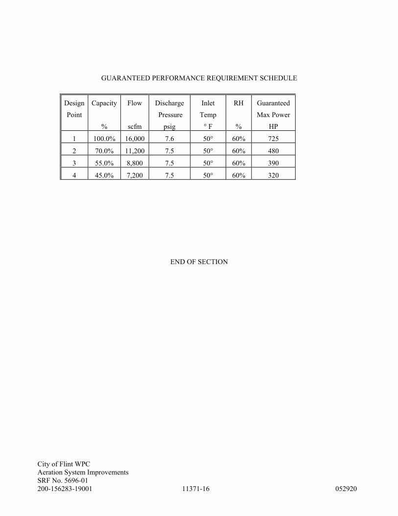
City of Flint WPC
Aeration System Improvements
SRF No. 5696-01
200-156283-19001 11371-16 052920
GUARANTEED PERFORMANCE REQUIREMENT SCHEDULE
Design
Point
Capacity
%
Flow
scfm
Discharge
Pressure
psig
Inlet
Temp
° F
RH
%
Guaranteed
Max Power
HP
1 100.0% 16,000 7.6 50° 60% 725
2 70.0% 11,200 7.5 50° 60% 480
3 55.0% 8,800 7.5 50° 60% 390
4 45.0% 7,200 7.5 50° 60% 320
END OF SECTION

City of Flint WPC
Aeration System Improvements
SRF No. 5696-01
200-156238-19001 11375-1 052920
SECTION 11375 - FINE BUBBLE AIR DIFFUSION EQUIPMENT
PART 1 - GENERAL
1.01 SUMMARY
A. Section Includes: Labor, materials, and equipment necessary for fabrication, production, installation,
and erection of the items specified in this Section as shown on Drawings or listed on Schedule.
B. Related Documents: Drawings and general provisions of the Contract, including General and
Supplementary Conditions, Division 1 Specification Sections, including Section 01600, apply to
Work of this Section.
1.02 REFERENCES
A. Reference Standards:
1. ANSI B-16.1 Pipe Flanges.
2. ASTM A 240 Stainless Steel Pipe Supports.
3. ASTM A 774 Stainless Steel Pipe.
4. ASTM A 778 Stainless Steel Pipe Fittings.
5. ASTM D 2564 PVC Pipe.
6. ASTM D 2855 PVC Pipe.
7. ASTM D 3034 PVC Pipe.
8. ASTM D 3915 PVC Pipe.
9. AWWA C-504 Butterfly Valves.
1.03 DEFINITIONS
A. "Oxygen Transfer" shall be defined as the pounds of oxygen absorbed per day per 1,000 cubic feet of
tank volume at standard conditions. Standard conditions shall be 20 degrees C, 760 mm mercury,
0.0 mg/l D.O. level, alpha = 1.0, and beta = 1.0.
B. "Dynamic Wet Pressure" is defined as the pressure to operate at the specified conditions minus
submergence and flow control losses.
C. "Diffuser Headloss" is defined as the headloss from the pod through the diffuser to the water.
D. "Orifice Loss" is defined as the headloss from the centerline of the header through the metering
orifice and into the pod or element holder.
1.04 SYSTEM DESCRIPTION
A. Design Conditions: Air supply equipment for this Project has been designed for actual in-waste
oxygen transfer efficiency at the mid-operating range air flow rate per diffuser grid as listed on
Schedule.
B. Performance Requirements: The equipment shall provide a fine pore wastewater aeration system
designed for full floor coverage of the aeration tanks using diffuser elements as specified under
Article 2.02, Components.

City of Flint WPC
Aeration System Improvements
SRF No. 5696-01
200-156238-19001 11375-2 052920
1.05 SUBMITTALS
A. Shop Drawings: Submit in accordance with Section 01330, Shop Drawings covering the items
included under this Section. Shop Drawing submittals shall include:
1. As-Constructed Drawings: Manufacturers shall furnish OWNER 4 sets of as-constructed
Drawings.
B. Test and Inspection Report: A written report shall be submitted to ENGINEER documenting testing
and/or inspection results. The report shall be prepared as noted under Section 01600.
C. Oxygen Transfer: Prior to any shop testing, manufacturer shall submit to ENGINEER for approval,
an outline of his test procedures including all formulas to be used in calculating oxygen transfer
efficiencies.
1. The results of the performance tests shall be submitted to ENGINEER in a written report. This
report shall include all raw data sheets, plots, and calculations. In addition, all results shall be
reported in a clear and concise manner, along with a written explanation of all pertinent
information dealing with testing or analysis of the data.
2. Manufacturer shall notify ENGINEER at least 1 month in advance of the scheduled test date in
order that they may arrange for an observer and also an estimate of the time required to perform
the tests.
D. Operation and Maintenance Manuals: Submit in accordance with requirements of Section 01600,
operation and maintenance manuals for items included under this Section.
E. Equipment Data Sheet: Prior to the taking of Bids for this Contract, as noted on Data Sheet included
in this Section, manufacturer of the equipment furnished under this Section shall furnish ENGINEER
the information listed on Equipment Data Sheets. The purpose of the Data Sheets is to furnish
OWNER necessary information so that an evaluation of the equipment can be accomplished.
F. Warranty: Submit in accordance with requirements of Section 01770, warranties covering the items
included under this Section.
1.06 QUALITY ASSURANCE
A. Oxygen Transfer: Certified documentation will be required to be submitted to ENGINEER.
PART 2 - PRODUCTS
2.01 MANUFACTURERS
A. Subject to compliance with specified requirements, manufacturers offering products which may be
incorporated in Work include:
1. Membrane Aeration Equipment:
a. Aquarius Technologies
b. EDI
c. ITT / Sanitaire.
d. SSI

City of Flint WPC
Aeration System Improvements
SRF No. 5696-01
200-156238-19001 11375-3 052920
2.02 COMPONENTS
A. The system shall include the vertical drop pipes, manifolds, air distribution headers, diffuser
assemblies, supports, expansion joints, diffuser pressure monitoring panels, and appurtenant
equipment necessary for a complete operating system. Diffuser layout shall provide a full-floor
coverage capable of providing uniform air dispersion per unit area.
1. The system shall be furnished with a hydrogen chloride gas cleaning system as specified and
shown on Drawings.
B. Drop Pipes: Existing portion of stainless steel drop pipe may be reused to connect to diffuser
manifold. The drop pipe is believed to be Schedule 5S, Type 304L stainless steel in accordance with
ASTM Standard A 778. Fittings shall be in accordance with ASTM Standard A 774 and be equal in
wall thickness to the pipe.
1. All fastening hardware shall be series 18-8 stainless steel. All connections shall be made using
125-pound drilled flanges. Flange bolts shall be Type 304 stainless steel with brass or bronze
nuts.
C. Manifolds: A manifold pipe shall be furnished and installed for each grid area that extends the full
width of the aeration tank. The manifold pipe and fittings shall be SDR 26, PVC conforming to
ASTM 3034 and 3915.
D. Air Distribution Headers: Air distribution headers shall be furnished and installed with a spacing that
provides uniform air dispersion per unit area. The header pipe and fittings shall be SDR 33.5, PVC
conforming to ASTM 3034 and 3915.
1. Design the diffuser grid layout to satisfy the following minimum requirements:
a. Minimum clearance of 12-inches from any wall to edge of diffuser.
b. Maximum clearance of 36-inches from any wall to edge of diffuser.
c. A minimum clear space of 1-inch between adjacent diffusers on the same header.
d. A maximum clear spacing of 36-inches between adjacent diffusers on same headers.
e. A minimum clear space of 6-inch between adjacent diffusers on adjacent headers.
f. A maximum clear spacing of 36-inches between adjacent diffusers on adjacent headers.
g. A minimum clear spacing of 10-inches from bottom of tank to diffusers.
2. Each diffuser grid shall be provided with at least 1 moisture purge connection. The moisture
purge shall consist of a 3/4-inch PVC blowoff line terminating at least 18 inches above the basin
water level with a 3/4-inch PVC ball valve. The blowoff line shall connect to a sump in the air
piping which shall collect condensate or water which enters through the diffusers when power is
off. The sump bottom shall be below the bottom elevation of the distribution headers. Provide a
1-inch diameter flexible connection where the moisture blowoff line connects to the header
system.
E. Membrane Diffuser Assemblies: Diffuser assemblies shall consist of round rubber membrane
diffusers, diffuser element holders, diffuser element retaining device(s), and airflow control orifices.
1. Diffuser element holders shall be PVC, polypropylene, or polyamide plastic, formed to support
the diffuser when the air supply is interrupted and hold the diffuser firmly in position during
operation. Diffuser element holders shall be securely attached to the header pipe, and shall
provide means for fastening the diffuser membrane in a fashion which precludes the possibility
of it coming loose.
City of Flint WPC
Aeration System Improvements
SRF No. 5696-01
200-156238-19001 11375-4 052920
2. Rubber membrane diffusers shall be fabricated from an EPDM rubber compound formulated by
the manufacturer specifically for use in air diffusers to be used in wastewater aeration.
Perforations for air discharge may be round holes or slits, formed by piercing the membrane
using methods which do not result in removal of any material to create the perforations.
Hole/slit size shall be determined by manufacturer to optimize oxygen transfer efficiency, and
minimize the potential for air side fouling.
3. Membrane thickness shall be determined by manufacturer who shall certify that, if operated at
air flow rates less than a manufacturer-stipulated maximum, the diffuser membrane will not
experience permanent deformation (elongation) or tearing at the air flow perforations for a
period of 5 years.
4. Diffuser membranes shall be retained by removable corrosion-resistant devices of PVC or
stainless steel construction which hold the entire edge of the membrane securely in place.
Intermittent clips or clamps shall not be acceptable.
F. Diffuser Pressure Monitoring Panels: Each diffuser grid shall be furnished with a monitoring panel
box, support brackets, polyethylene tubing, PVC carrier pipe, and fittings to monitor air distribution
header pressure, diffuser element holder plenum pressure, and submergence pressure.
1. Three diffusers in each grid shall be instrumented to monitor diffuser headloss and orifice
losses. The 3 diffusers to be monitored shall be selected by ENGINEER, and may be located
anywhere in the grid.
2. The monitoring panel shall be of fiberglass construction, made watertight with a continuous
gasket along the sealing face of the panel door. The panel door shall be provided with a 1/4-turn
handle and piano hinge. Panel support shall be as shown on Drawings.
3. Pressure sensing lines shall be polyethylene tubing with polypropylene fittings. Each sensing
line shall be provided with a PVC ball valve and quick coupling connection compatible with the
portable gas cleaning mounting panel. The submergence pressure bubbler tube shall be 1/2-inch
diameter, and other sensing lines shall be 3/8-inch diameter. Sensing lines shall be housed in a
1-1/2-inch diameter Schedule 80 PVC carrier pipe. The carrier pipe shall be supported from the
drop pipe using stainless steel angles, U-bolts, and fastening hardware. Each panel shall be
equipped with polypropylene quick disconnect fittings for connection to the portable monitoring
panel to each grid.
2.03 ACCESSORIES
A. Spare Parts: The aeration equipment manufacturer shall supply the following spare parts:
1. 50 each membrane diffusers.
2. 50 each O-rings or gaskets.
3. 15 each diffuser hold-down rings.
4. 4 each lengths of diffuser header piping with the diffuser connector spacings at the minimum
spacing used on the project (length similar to average length used).
5. 4 each Header expansion fittings.
B. Supports: Manifold and header supports shall be designed to withstand pipe bouyant forces with a
2.0 factor of safety. Support spacings shall not exceed 8'-0" and supports shall be provided at the
ends of all pipework.
1. All pipe supports shall be designed to provide 2-inch vertical and 1/2-inch horizontal
adjustment for field alignment of the piping system.
2. Manifold and header pipe supports shall be Type 304 stainless steel. Supports shall be fastened
to the aeration tank floor using stainless steel expansion anchors designed to withstand applied
pull-out forces with a 4.0 factor of safety. Expansion anchors shall have 3-inch embedment

City of Flint WPC
Aeration System Improvements
SRF No. 5696-01
200-156238-19001 11375-5 052920
minimum. Fixed and guide supports shall be provided and arranged to be compatible with
expansion joint installation. Fixed header supports shall consist of a 1-1/2-inch-wide hold-down
clamp contoured to the pipe perimeter. The clamping device shall positively grip the air
distribution header when tight and be self-limiting to prevent over-stressing of the air header if
the clamp is over-tightened. Guide supports shall consist of a 2-inch-wide guide strap for the
manifolds and a 1-1/2-inch-wide guide strap for the headers contoured to the pipe perimeter.
The guide clamp edges shall be chamfered to avoid binding between the pipe and guide clamp.
A sliding surface shall be provided between the clamp and pipe to minimize resistance to
movement. A 1/8-inch clearance shall be provided between the sliding surface and the pipe. A
self-limiting feature shall be provided to maintain the specified clearance if the clamp is over-
tightened.
C. Expansion Joints: PVC expansion joints shall be provided on the air distribution headers at intervals
to accommodate thermally induced stresses due to expansion and contraction. Expansion joints shall
be airtight and permit force movement of the header plain end within the joint barrel. The expansion
joint seal shall be by an O-ring gasket made from polyisoprene. The O-ring shall be held in place by
a threaded retainer ring. The expansion joint shall be designed for a 4-inch minimum stroke with an
average 50-pound operating force or design calculations and details shall be provided to allow travel
for a 125 degrees F temperature change. The number and location of expansion joints in each
diffuser grid shall be as recommended by manufacturer and approved by ENGINEER. A preliminary
layout of expansion joints shall be included with the Equipment Data Sheet.
D. Portable Monitoring Panel: A portable monitoring panel shall be provided for connection to the
diffuser pressure monitoring panels. The portable panel shall contain a vapor actuated differential
pressure gauge with 3-1/2-inch face and 0 - 30-inch w.c. range suitable for outdoor exposure; a 0 -
5 scfh rotameter; and isolation valves and polyethylene tubing for connection to the fittings in the
diffuser pressure monitoring panels.
1. The portable panel shall be arranged as shown on Drawings so that the differential pressure
gauge can measure pressure drop between the air header and the diffuser plenum, between the
air header and the bubbler, and between the diffuser plenum and the bubbler. The rotameter
shall measure airflow to the submergence bubbler.
2.04 FABRICATION
A. System: Air diffusion system shall not be fabricated until ENGINEER has approved the oxygen
transfer test results.
B. Pipe and Fittings: The PVC resin used for all pipe and fittings shall be treated for ultraviolet light
exposure by adding 2 parts (by weight) of titanium dioxide per 100 parts of resin.
C. Drop Pipes: All welding shall be completed at the point of fabrication using the shielded arc or inert
gas method. Where filler wire is used, it shall be the same material as the parent metal. Butt welds
shall have full penetration to the interior surface and gas shielding provided to the interior and
exterior of the joint. Weld beads shall be smooth and evenly distributed with an interior projection
not exceeding 1/16 inch beyond the pipe or fitting I.D. Face ring angles and follower flanges shall be
continuously welded, both sides.
1. Weld splatter shall be removed using a stainless steel wire brush. Fabricated assemblies shall be
completely immersed in a pickling solution of 6 percent nitric acid and 3 percent hydrofluoric
acid to remove carbon deposits, grease, and oils. Following the pickling process, the assembly

City of Flint WPC
Aeration System Improvements
SRF No. 5696-01
200-156238-19001 11375-6 052920
shall be neutralized by immersion in a tri-sodium phosphate rinse to regenerate a uniform,
chromium oxide film.
D. Manifolds: The manifolds shall be fabricated with 4-inch-diameter flanged stubs for connection to
the distribution headers. Connections to the manifold shall be reinforced with solvent-welded saddle
tees.
1. All joints shall be factory solvent welded in accordance with ASTM D 2855. Solvent cements
shall be suitable for use with PVC and conform to ASTM D 2564 requirements.
E. Air Distribution Headers: The distribution headers shall be fabricated with the diffuser element
holder factory solvent welded to the crown of the header. Diffuser element holders shall be attached
so that they can resist the following applied torques:
1. About the holder polar axis 150 foot-pounds.
2. About the holder longitudinal axis 100 foot-pounds.
3. Distribution headers shall be fabricated in sections not to exceed 20 feet in length. Sections of
distribution headers shall be connected with joints as specified herein.
F. Diffuser Element Holder: All diffuser element holder joints shall be factory solvent welded in
accordance with ASTM D 2855. Solvent cements shall be suitable for use with PVC and shall
conform to ASTM D 2564 requirements.
G. Supports: Pipe supports, including supports for moisture purge lines, shall be fabricated from
Type 304L stainless steel for welded assemblies and Type 304 stainless steel for nonwelded parts.
Materials shall conform to ASTM A 240-78. All welding shall be completed at the point of
fabrication using shielded arc or inert gas methods. All welds shall be stainless steel wire brushed.
Fabricated assemblies shall be immersed in a pickling solution of 6 percent nitric acid and 3 percent
hydrofluoric acid. Following the pickling solution, the fabricated assembly shall be immersed in a
tri-sodium phosphate solution to regenerate a uniform chromium oxide corrosion-resistant film.
H. Expansion Joints: The expansion joint barrel shall be factory solvent welded to one end of the
distribution header.
2.05 SOURCE QUALITY CONTROL
A. Testing: Where noted on Schedule, aeration equipment manufacturer shall conduct factory tests of
the equipment to demonstrate its capability to achieve the specified oxygen transfer and head loss
requirements at the specified conditions. The tests shall be conducted at aeration equipment
manufacturer's facility, as a condition of acceptance prior to fabrication of the air diffusion system.
Testing shall be done in conformance with the ASCE Standard for Measurement of Oxygen Transfer
in Clean Water, 1984.
1. If the equipment does not meet the guaranteed oxygen transfer efficiency or the guaranteed
headloss as demonstrated by shop testing, the equipment shall be rejected by ENGINEER.
B. Diffuser Assemblies: Diffuser elements shall be tested by submerging the unit in at least 2 inches of
tap water.
1. Manufacturer shall randomly select diffuser elements from each lot manufactured for testing.
The number tested shall be in accordance with Military Standard 105D, Table I, Inspection
Level II or 0.2 percent, whichever is greater. These diffuser elements shall be tested for specific
permeability, hydrostatic load, dynamic wet pressure, and dimensional tolerances. Tested
diffuser elements shall be marked for identification. A test report shall be submitted to

City of Flint WPC
Aeration System Improvements
SRF No. 5696-01
200-156238-19001 11375-7 052920
ENGINEER summarizing the test procedures and results. The sampling results shall
demonstrate a value of percent defective of less than 1.5 percent of the total units furnished.
2. Equipment manufacturer shall test diffuser assemblies similar to those to be furnished.
PART 3 - EXECUTION
3.01 ERECTION
A. Equipment furnished and installed under this Section shall be fabricated, assembled, erected, and
placed in proper operating condition in full conformity with detail drawings, specifications,
engineering data, instructions, and recommendations of equipment manufacturer as approved by
ENGINEER.
3.02 EXAMINATION
A. Installation Check: Manufacturer shall provide the services of a factory-trained representative to
check the equipment once prior to installation to review installation procedures with
CONTRACTOR, and once after installation to inspect, check, adjust if necessary, and approve
equipment's installation.
1. Manufacturer shall provide the services of a factory-trained representative to instruct OWNER’s
personnel in all aspects of system operation and maintenance. Such instruction shall take place
immediately after system start-up. Manufacturer shall allow for 3 trips to the Site and a total of
6 person-days to account for the above-stated installation checks.
3.03 ERECTION, INSTALLATION AND APPLICATION
A. Supports: After pipe installation, the tank shall be filled with water to the level of the diffuser
element holders. Header pipe supports shall be adjusted so that diffuser elements are level within
plus or minus 1/4 inch. The air shall be turned on with the diffuser elements off, and the headers
blown out and cleaned prior to diffuser element installation.
3.04 FIELD QUALITY CONTROL
A. Tests: Where noted on Schedule, equipment manufacturer shall conduct on-site mixing tests of the
equipment to demonstrate its capability to maintain uniform suspension of tank contents.
B. Expansion Anchors: All expansion anchors shall be field tested following installation to verify their
pull-out resistance. Anchors that fail to meet the pull-out test shall be replaced or supplemented by
additional anchors.
3.05 DEMONSTRATION
A. Training: Where herein specified, manufacturer shall provide the services of a factory-trained
representative to instruct OWNER's personnel.

City of Flint WPC
Aeration System Improvements
SRF No. 5696-01
200-156238-19001 11375-8 052920
MEMBRANE FINE BUBBLE AERATION EQUIPMENT
EQUIPMENT DATA SHEET
Page 1 of 2
The manufacturer of this equipment shall submit to ENGINEER, 72 hours prior to the Bid date, the following
specific data on the equipment being offered. The purpose of this information is to provide OWNER the
information necessary to evaluate the equipment. Failure by a manufacturer to furnish all the information
requested shall be cause for rejection of the equipment. Any exceptions to these Specifications must be noted
and included with the information submitted with this form. Exceptions may be cause for rejection of the
equipment. A minimum of 1 week prior to the taking of Bids on this Contract, manufacturers will be advised
whether their equipment has been approved, and an Addendum will be issued listing the names of all approved
equipment manufacturers and the total number of diffusers each will be required to provide. Equipment
manufactured by manufacturers not listed shall not be acceptable. Exceptions to the Specifications, unless
specifically addressed in the Addendum, are not approved.
A. DYNAMIC WET PRESSURE
List the dynamic wet pressure of a clean, new, individual diffuser in tap water at the listed airflow rates:
Dynamic wet pressure is the total pressure required at the listed airflow for a diffuser submerged a
minimum of 2-inches, minus submergence and distribution orifice losses.
B. PERMEABILITY
List the dry permeability of a clean, new diffuser at the listed airflow rates.
Permeability is the airflow rate in scfm per square foot of diffuser surface area at a pressure differential of
2-inches water column.
C. CLEAN WATER OXYGEN TRANSFER EFFICIENCY
List the non-steady-state oxygen transfer efficiency of a diffuser grid in tap water at 20 degrees C,
14.7 psia, and 0.0 mg/l D.O. at the indicated air flow rates per diffuser, at a diffuser submergence of 12’-
2”. Attach supporting test data.
D. IN-WASTE OXYGEN TRANSFER EFFICIENCY
List the steady-state oxygen transfer efficiency of a diffuser grid in mixed liquor (in a functioning aeration
tank) corrected to standard conditions of 20 degrees C, 14.7 psia, and 0.0 mg/l mixed liquor D.O. at the
indicated air flow rates per diffuser, adjusted to a diffuser submergence of 12’-2”. Attach supporting test
data and a detailed description of test procedures and the test location with wastewater parameters. Test
data and procedures for in-waste testing conducted by Tetra Tech MPS need not be submitted
(continued)

City of Flint WPC
Aeration System Improvements
SRF No. 5696-01
200-156238-19001 11375-9 052920
Page 2 of 2
Air Flow A. DWP B. Permeability C. Clean Water D. In-Waste
per Diffuser (in w.c) (scfm/sf) OTE % OTE%
0.5 scfm
1.0 scfm
1.5 scfm
2.0 scfm
2.5 scfm
3.0 scfm
E. ASSEMBLY
Attach a detailed arrangement drawing for one complete drop assembly, complete, including quick
disconnect coupling, riser pipe, header, diffuser assembly, adjustable support legs, details and locations of
expansion joints, and junction box. Indicate all pipe diameters, materials, thickeners (Schedule, SDR,
etc.), etc.
F. PERFORMANCE GUARANTEE
The aeration equipment manufacturer guarantees the clean water oxygen transfer efficiency (Item C) of
the equipment configuration he proposes to furnish. Number of drops, submergence and riser and header
pipe sizes shall be as shown on Drawings.
G. INSTALLATION DATA
Attach a list of five installations where the proposed air diffusion equipment has been installed and
operated in a municipal wastewater treatment facility. State number of diffusers installed, treatment
capacity of the plant in mgd, contact person name, address, and telephone number.
By:
Representing:
Telephone:
Date:

City of Flint WPC
Aeration System Improvements
SRF No. 5696-01
200-156238-19001 11375-10 052920
FINE BUBBLE AIR DIFFUSION EQUIPMENT SCHEDULE:
Type: 9-inch Diameter Membrane Diffuser
No. of Tanks: 1 tank, 4 passes
No. Drops per pass: 3 (existing)
Tank Dimensions
Length: 200’
Width: 24’
Depth: 15’
SWD: 13’
Submergence: 12’-2”
Actual Oxygen Requirement: 14,300 lbs/day/tank Max day
Required Dissolved Oxygen: 2.0 mg/L
Remarks: Existing Zone Information to match
Aeration Zones No. of Grids No. of Headers Min. No. of Diffusers
1 1 8 480
2 1 7 320
3 1 7 250
4 1 8 480
5 1 7 320
6 1 7 250
7 1 7 175
8 1 7 150
9 1 7 150
10 1 7 150
11 1 7 150
12 1 7 150
END OF SECTION

City of Flint WPC
Aeration System Improvements
SRF No. 5696-01
200-156238-19001 11376-1 052920
SECTION 11376 - COMPRESSED GAS MIXING SYSTEM
PART 1 – GENERAL
1.01 SCOPE
A. General: Furnish, install and test packaged compressed air mixing system.
B. This section covers the furnishing of a compressed gas mixing system for the Battery B
Aeration Basins (Pass 4) and Channels including compressors, receivers, master control panel,
remote I/O panel, valve modules, header supply piping, nozzle headers, nozzles, auxiliary
equipment and accessories as specified herein and shown on Contract Drawings.
C. The system design in based on Enviromix (Basis of Design). The mixing system in integral to
the operation of the existing aeration tanks and channels. Approval by ENGINEER is required
for any proposed deviations from the basis of design.
D. Refer to system configuration drawing sheet I-100 for requirements on PLC hardware,
panelview and ethernet switch information. Manufacturer responsible for providing IO cards
as required to suit the process equipment being provided. PLC hardware to be
Rockwell. Provide Rockwell panelviews- model as noted. Ethernet switches to be
Hirschman- model as noted on drawings
E. Section Includes: Labor, materials, and equipment necessary for fabrication, production,
installation, and erection of the items specified in this Section as shown on Drawings or listed
on Schedule.
1.02 DESCRIPTION
A. The system shall intermittently and sequentially inject compressed air through fixed nozzles
located on the basin floor to create large bubbles which effectively mix the basin contents
using no moving parts located within the basin with negligible oxygen transfer from the
mixing system to the bulk liquid.
B. Manufacturer shall meet the performance requirement to maintain a mixed system.
1.03 REFERENCES
A. ASTM International (ASTM)
1. A240/A240M, Standard Specification for Chromium and Chromium-Nickel Stainless
Steel Plate, Sheet, and Strip for Pressure Vessels and General Applications.
2. A276, Standard Specification for Stainless Steel Bars and Shapes.
3. A312, Standard Specification for Seamless, Welded, and Heavily Cold Worked
Austenitic Stainless Steel Pipe
4. A380, Standard Practice for Cleaning, Descaling, and Passivation of Stainless Steel Parts,
Equipment, and Systems
City of Flint WPC
Aeration System Improvements
SRF No. 5696-01
200-156238-19001 11376-2 052920
1.04 DEFINITIONS
A. Basin: The structure within which mixing occurs; i.e., Anoxic/Swing Zones, Channels,
Aeration Tanks, Equalization Tank, etc.
B. Main Air Header Pipe: Piping from compressor to valve modules.
C. Header Supply Pipe: Piping between a valve module and respective nozzle headers.
D. Nozzle Header: Continuous (i.e., not branched) horizontal piping with nozzle offsets, with
single inlet connection to header supply pipe and outlet offset connections to nozzles.
E. Nozzle Drop Leg: Piping branching off nozzle header trunk piping which connects to nozzles
either at a 90-degree angle (offset drop leg) or vertically (straight drop leg).
F. Nozzle: Floor-anchored, large bubble-emitting device.
G. Standard Cubic Feet per Minute (scfm): Air at 68° F, 14.7 psia, and 0 percent relative
humidity as defined by the Compressed Air & Gas Institute.
H. Actual Cubic Feet per Minute (acfm): Flow rate of air at the standardized reference condition
(ISO 1217) delivered to the terminal point of the compressor package.
I. Master Control Panel (MCP): Control panel that controls the mixing system including the
solenoid-actuated air control valves (ACVs) in one or more remote VMs.
J. Valve Module (ZVM): Enclosure with solenoid-actuated air control valves controlled remotely
by the MCP controller or locally factory programmed controller. Valves are in a common
manifold which receives and distributes compressed air bursts intermittently to header supply
pipes.
1.05 SUBMITTALS
A. The following items shall be submitted with the Shop Drawings:
1. Catalog data or illustrations showing principal parts and materials.
2. A complete set of all layout drawings and details including complete assembly and
installation drawings including overall equipment layout and piping interconnection
drawings.
3. Complete electrical schematics and field termination drawings.
4. Complete data for accessory items.
5. Detailed specifications and data including the following:
a. Compressors
1) Manufacturer
2) Type and model
3) Rotative speed
4) Dimensions
5) Weight including motor
6) Performance data
7) Bearing data
8) Separator details
9) Filter details

City of Flint WPC
Aeration System Improvements
SRF No. 5696-01
200-156238-19001 11376-3 052920
10) Accessory details
11) Piping schematic
12) Control equipment
13) Sequence of operation
b. Motors
1) Manufacturer
2) Type and model
3) Horsepower rating and service factor
4) Insulation class
5) Temperature rise full load
6) Rotative speed
c. Particulate and Coalescing Filters, as applicable
1) Manufacturer
2) Type and model
3) Pressure drop
6. Test or performance data that the system does not contribute measurable oxygen into the
process stream.
7. Compressor support locations and loads transmitted to bases and foundations.
8. Compressor electrical schematics and field termination wiring.
9. List of recommended spare parts.
10. Qualifications of field service engineer.
11. Recommendations for short and long-term storage.
12. Special tool requirements.
13. Testing procedures.
14. Full scale test results from a minimum of ten (10) U.S. compressed gas mixing system
installations demonstrating that the compressed gas mixing system achieved
homogeneous mixing as substantiated through statistical analysis of Total Suspended
Solids (TSS) samples yielding a Coefficient of Variation (Cv) of 10%.
15. Installation reference of not less than ten (10) separate North American installations of
compressed air mixing systems similar to that required for the Project in satisfactory
operation for at least two (2) years and not less than five (5) separate North American
installations of compressed air mixing systems with nozzle quantity not less than required
for this Project. Installations shall be where the Manufacturer supplied compressors,
receivers, control panels, header supply piping, nozzle headers and nozzles. For each
installation, submit the following information: name of facility owner, facility name,
facility location including city and state, facility operation and maintenance contact
person including name and telephone number, equipment model number and motor size,
nozzle quantity, and month and year that equipment was place into continuous service.
1.06 WARRANTY
A. The Compressed Gas Mixing Manufacturer shall guarantee the equipment against defects in
materials and workmanship under normal use and service, to the original purchaser, for a
period of twelve (12) months from date of equipment startup by an authorized technician or
eighteen (18) months from date of equipment shipment, whichever is the lesser.
B. Requirements to maintain the compressor warranty are:
1. Factory Authorized start-up by a representative of the Compressor Manufacturer
distributor/factory store.
2. OEM filters and oil used at the intervals described in the compressor O&M manual.

City of Flint WPC
Aeration System Improvements
SRF No. 5696-01
200-156238-19001 11376-4 052920
3. Oil samples are to be taken and analyzed every 4,000 hours of run-time or as defined in
compressor O&M manual or once a year.
4. Maintenance in accordance with compressor Manufacturer’s operating and maintenance
instruction.
1.07 QUALITY ASSURANCE
A. The compressed gas mixing system shall be furnished by a single Manufacturer who has a
minimum of ten (10) years’ experience producing substantially similar equipment and shall
have provided a minimum of five (5) individual systems of similar size of not less than the
specified minimum quantity of nozzles for this Project in satisfactory operation for at least two
(2) years.
B. The equipment shall be designed, constructed, and installed in accordance with the best
practices and methods. The system manufactured by EnviroMix, Inc. of Charleston, SC, was
utilized as the basis of design. Any substitutions shall be approved by ENGINEER.
C. This specification includes patented technology under US Patents 6280636, 8505881,
8702070, 9416037.
D. The Contractor shall obtain the compressors, receivers, control panels, header supply piping,
nozzle headers, nozzles and appurtenances from the compressed gas mixing system
Manufacturer, as a complete and integrated package to insure proper coordination and
compatibility and operation of the system.
E. Alternate Manufacturer’s wishing to offer their equipment must submit the following
information to the Engineer in a Pre-Qualification Package within fourteen (14) days prior to
the published date of Bid Closing. Engineer will evaluate information and if in the Engineer’s
sole discretion, the Alternate Manufacturer’s proposed compressed gas mixing system meets
the specification, performance and offers equal quality and experience to the basis of design,
the Alternate Manufacturer will be added to the compressed gas mixing specification via
addendum.
1. A complete set of drawings, specifications, catalogue cut sheets, and detailed descriptive
material of proposed major equipment items. This information shall identify all technical
and performance requirements stipulated on each drawing and in each specification
section.
2. Full scale test results from a minimum of ten (10) U.S. installations demonstrating that
the compressed gas mixing system achieved homogeneous mixing as substantiated
through statistical analysis of Total Suspended Solids (TSS) samples yielding a
Coefficient of Variation (Cv) of 10% or less at nozzle densities +/- 10% of the density
specified for this project.
3. Test or performance data that the compressed gas mixing system does not contribute
measurable oxygen into the process stream.
4. Full scale test results from a minimum of two (2) U.S. installations demonstrating that the
compressed gas mixing system does not negatively impact biological nitrogen and/or
phosphorus removal.
5. Written confirmation from Authorized Officer of the Company that the proposed
compressed gas mixing system includes complete Unit Responsibility with all
components specified in Section 46 41 26 – Compressed Gas Mixing System as well as
the specified Field Performance Testing and Guarantee.

City of Flint WPC
Aeration System Improvements
SRF No. 5696-01
200-156238-19001 11376-5 052920
6. Installation reference list including a minimum of ten (10) U.S. compressed gas mixing
installations for which the supplier furnished and integrated the complete compressed gas
mixing system, including compressors, receivers, control panels, header supply piping,
nozzle headers and nozzles. Provide facility name/location, design average daily flow,
contact name/telephone number and start-up date for each installation.
7. Installation reference of not less than ten (10) separate North American installations of
compressed air mixing systems similar to that required for the Project in satisfactory
operation for at least two (2) years and not less than five (5) separate North American
installations of compressed air mixing systems with nozzle quantity not less than required
for this Project.
8. List of recommended spare parts.
9. Equipment field installation requirements.
10. A maintenance schedule with projected labor hours showing the required maintenance,
frequency of maintenance, lubricants and other items required at each regular
preventative maintenance period.
11. Reviewed specification with each paragraph marked noting full compliance and detailed
written documentation with discussion of all deviations from the specification.
12. Letter from a Surety indicating that the Manufacturer is pre-approved to receive a two (2)
year performance bond.
F. Should the Contractor choose equipment from a Manufacturer of an acceptable equivalent
product, any additional costs required to accommodate such equipment, including any changes
to the field air piping, power distribution or additional Engineer review time, shall be made
without a change in the Contract Price or Contract Time and at no additional cost to the Owner
G. A performance bond from the Manufacturer guaranteeing the replacement of the acceptable
equivalent product shall be provided with the submittal package. The bond term shall be for a
period of two (2) years. If the operation of the acceptable equivalent compressed gas mixing
system as determined by the Owner is unsatisfactory, the Contractor shall repair, modify or
replace the entire system to include the compressed air equipment system with appurtenances,
in a manner acceptable to the Owner. If the Contractor fails to correct deficiencies identified
by the Owner within six (6) months of the date first notified in wiring, the Owner shall, at its
own discretion make all necessary repairs or replacement and deduct all associated costs from
the performance bond.
PART 2 – PRODUCTS
2.01 PERFORMANCE AND DESIGN REQUIREMENTS
A. Provide a compressed gas mixing system for the Battery B Aeration Basins (Pass 4) and
Channels. The system shall intermittently and sequentially inject compressed air through
fixed nozzles located on the basin floor to create large bubbles which mix the basin contents
using no moving parts located within the basin with negligible oxygen transfer from the
mixing system to the bulk liquid.
B. Basin mixing shall be uniform throughout the basin with effective mixing confirmed through a
Field Performance Test as specified.
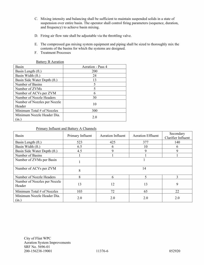
City of Flint WPC
Aeration System Improvements
SRF No. 5696-01
200-156238-19001 11376-6 052920
C. Mixing intensity and balancing shall be sufficient to maintain suspended solids in a state of
suspension over entire basin. The operator shall control firing parameters (sequence, duration,
and frequency) to achieve basin mixing.
D. Firing air flow rate shall be adjustable via the throttling valve.
E. The compressed gas mixing system equipment and piping shall be sized to thoroughly mix the
contents of the basins for which the systems are designed.
F. Treatment Processes
Battery B Aeration
Basin Aeration - Pass 4
Basin Length (ft.) 200
Basin Width (ft.) 24
Basin Side Water Depth (ft.) 13
Number of Basins 5
Number of ZVMs 5
Number of ACVs per ZVM 6
Number of Nozzle Headers 30
Number of Nozzles per Nozzle
Header 10
Minimum Total # of Nozzles 300
Minimum Nozzle Header Dia.
(in.) 2.0
Primary Influent and Battery A Channels
Basin Primary Influent Aeration Influent Aeration Effluent Secondary
Clarifier Influent
Basin Length (ft.) 523 425 377 140
Basin Width (ft.) 6.5 6 10 6
Basin Side Water Depth (ft.) 4.5 9 9 9
Number of Basins 1 1 1 1
Number of ZVMs per Basin 1
1
Number of ACVs per ZVM 8
14
Number of Nozzle Headers 8 6 5 3
Number of Nozzles per Nozzle
Header 13 12 13 9
Minimum Total # of Nozzles 103 72 65 22
Minimum Nozzle Header Dia.
(in.) 2.0 2.0 2.0 2.0

City of Flint WPC
Aeration System Improvements
SRF No. 5696-01
200-156238-19001 11376-7 052920
Battery B Channels
Basin Aeration
Influent
Aeration
Effluent
Section 1
Aeration
Effluent
Section 2
Aeration Effluent
Section 3
Secondary
Clarifier Influent
Basin Length (ft.) 466 400 295 240 164
Basin Width (ft.) 9 10 10 10 10
Basin Side Water Depth (ft.) 4.5 9 9 9 9
Number of Basins 1 1 1 1 1
Number of ZVMs 1
1 1
Number of ACVs per ZVM 13 4 5
Number of Nozzle Headers 7 6 4 3 2
Number of Nozzles per Nozzle
Header 14 12 12 13 14
Minimum Total # of Nozzles 98 72 48 39 28
Minimum Nozzle Header Dia.
(in.) 2.0 2.0 2.0 2.0 2.0
G. Performance Requirements
1. The compressed gas mixing system Manufacturer shall be responsible for sizing and
selecting all system components to meet the requirements of the field mixing
performance test specified herein. The compressor size, number of nozzles and piping
size specified herein and shown on the Drawing are minimum. Any increase in the
number and size of system components to meet the requirements of the field mixing
performance test shall be at no additional cost to the Owner.
2.02 MATERIALS
A. Main Air Header Supply Piping
1. The main air header supply piping from compressors to Valve modules shall be furnished
and installed by CONTRACTOR.
2. Sch 5S, stainless steel Press technology system (Viega, or equal), comprised of stainless
steel Press technology fittings, couplings, and pipe, unless specified otherwise. Per the
requirements of Section 15105 and 15212.
3. Maximum working pressure of 150 psi.
4. Couplings and fittings: Press technology products formed of Type 304/304L stainless
steel tubing including a self-contained o-ring seal(s) molded of synthetic FKM rubber.
5. Pipe: Type 304/304L ASTM A312 stainless steel.
B. Header Supply Piping
1. Provide threaded connections only where required.
2. Sch 5S, stainless steel Press technology system (Viega, or equal), comprised of stainless
steel Press technology fittings, couplings, and pipe, unless specified otherwise.
3. Maximum working pressure of 150 psi.
4. Couplings and fittings: Press technology products formed of Type 304/304L stainless
steel tubing including a self-contained o-ring seal(s) molded of synthetic FKM rubber.
5. Pipe: Type 304/304L ASTM A312 stainless steel.
C. Nozzle Headers
1. Sch 10S, 304/304L stainless steel with 1” Sch 40S, stainless steel nozzle offsets

City of Flint WPC
Aeration System Improvements
SRF No. 5696-01
200-156238-19001 11376-8 052920
2. Nozzle couplings: 1” NPT, 150 lb, 304/304L stainless steel
3. Delivered from the Manufacturer pre-assembled to the extent practicable to minimize
field assembly error and installation time.
4. Pipe: Type 304/304L ASTM A312 stainless steel.
5. Provide nozzle headers in maximum 20-ft segments with two bolt 304/304L stainless
steel flexible gasketed coupling connections. Flexible couplings shall be rated for a
maximum working pressure of 150 psi.
6. Provide nozzle headers with removable end caps to facilitate clean-out.
D. Nozzles
1. Top plate fabricated from 1/8” stainless steel plate, ASTM A240/A240M, Type 304/304L
with a 2D finish.
2. Bottom plate fabricated from HDPE and gasketed to prevent air from leaking between the
top plate and the bottom plate.
3. Top and bottom nozzle plates shall be joined together using Type 304/304L stainless
steel hardware. Nozzles shall come pre-assembled.
4. Nozzles shall be designed with adequate strength to withstand vertical thrust of mixing
air.
5. Threaded Rod Anchors: Use Hilti HIT-RE 500 adhesive or equal to be provided by the
Contractor. A minimum of two threaded rods shall be installed per nozzle for flat floor
installations, one each on opposite diagonal corners. Three threaded rods shall be
installed per nozzle for slope floor installations.
6. Nozzles shall be installed in the locations as shown on the Drawings.
E. Appurtenances
1. Miscellaneous: Nuts, bolts, washers, threaded rod, and other non-welded parts shall be
stainless steel, ASTM A240/A240M, Type 304. Threaded assemblies shall be chemically
treated or lubricated prior to assembling to prevent galling.
F. Fabrication
1. The piping used for the air mixing system shall be Type 304/304L stainless steel unless
otherwise noted.
2. Shop fabricate welded metal parts and assemblies from stainless steel,
ASTM A240/A240M, Type 304/304L with a 2D finish.
3. Shop fabricate non-welded parts and pieces from sheets and plates of stainless steel,
ASTM A240/A240M, Type 304 or from bars of stainless steel ASTM A276, Type 304,
unless specified otherwise.
4. Welds and Welding Procedure
a. Shop weld with filler wire using MIG, TIG or shield-arc, or plasma-arc welding
inert gas processes. Provide a cross-section equal to or greater than parent metal.
b. Provide full penetration welds to interior surface with gas shielding to interior and
exterior of joint.
c. Provide smooth, evenly distributed interior weld beads with an interior projection
not exceeding 1/16 inch beyond inner diameter of nozzle header or fittings.
d. Field welding is not permitted.
e. Clean all welded stainless steel surfaces and welds after fabrication to remove weld
splatter and finish clean all exterior welds, carbon deposits and contaminants by
passivation per ASTM A380 Section 6.2.11.

City of Flint WPC
Aeration System Improvements
SRF No. 5696-01
200-156238-19001 11376-9 052920
2.03 MASTER CONTROL PANEL (MCP)
A. General Requirements
1. Refer to system configuration drawing sheet I-100 for requirements on PLC hardware,
panelview and ethernet switch information. Manufacturer responsible for providing IO
cards as required to suit the process equipment being provided. PLC hardware to be
Rockwell. Provide Rockwell panelviews- model as noted. Ethernet switches to be
Hirschman- model as noted on drawings.
2. Coordinate IP addresses with Owner.
3. PLC logic and panelview graphics shall conform to the owners existing software
programming standards. Coordinate with Owner prior to programming of these
manufacturer supplied systems.
4. Furnish to owner actual electronic program copies of the PLC programs and the
panelview applications. These applications shall be integrated to the existing plant-wide
SCADA system by Tetra Tech.
5. Coordinate with Tetra Tech on any signals needed from the existing plant wide SCADA
system for automatic operation of the manufacturer supplied systems. These signals will
be messaged over the plant wide fiber optic/SCADA network.
6. Panelview applications to have at a minimum 3 levels of password security. Coordinate
exact requirements with Tetra Tech.
7. PLC’s panelview’s, and switches to be powered by an on-line UPS. Provide bypass
contactor for bypassing the UPS in the event of a failure.
8. Panels to be provided with input surge protection.
9. Panels to be provided with step-down transformers externally mounted as required.
10. The panelview programming shall include at a minimum software manual operation of
the equipment from the panelview. Software automatic operation shall be provided as
specified herein and as coordinated with Owner/Tetra Tech.
11. Furnish fiber optic patch panels as show on instrumentation drawings.
12. Furnish ethernet patch cables as shown. Furnish duplex multimode fiber optic patch
cables- 50 micron as shown. Connectors as noted on drawings.
B. Wall Mount or Free Standing Enclosure: MCP shall have UL-rated NEMA 4 painted steel
enclosure and be rated for a maximum ambient temperature of 104°F.
C. Power Connection: MCP shall accept a single source 120 VAC power connection. Lightning
and surge protection shall be provided on the incoming line power.
D. Operator Interface Terminal (OIT): The MCP shall have an OIT to make operating parameter
changes and acknowledge alarms. The OIT shall be an Allen Bradley 10” Panelview Plus 7
color touchscreen. The OIT shall have flash memory capacity, USB port, and Ethernet
communication.
E. Controller: MCP shall be equipped with an Allen Bradley CompactLogix 5069-L306ER
controller which controls the mixing system including sequence, duration, and frequency of
the air control valve (ACV) openings in each valve module (VM). The controller shall also
provide network communication capabilities via Ethernet IP protocol.

City of Flint WPC
Aeration System Improvements
SRF No. 5696-01
200-156238-19001 11376-10 052920
F. Ethernet Switch: MCP shall include a Hirschmann Model RS20-0800M2M2SAE Ethernet
switch.
G. Nameplate: A stainless steel nameplate shall be provided on the control panel. The nameplate
shall be securely fastened in a conspicuous place and clearly inscribed with the Manufacturer’s
name, year of manufacture, and serial number.
H. Control and Operation
1. Control Features: All control features shall be adjustable from the OIT provided by the
mixing system Manufacturer. Control features shall be adjustable at any time during the
operation of the system. Control features shall be initially set according to Manufacturer
recommendations.
2. Mixing Parameters: The operator shall be able to enable/disable mixing operation, select
the firing sequence, the firing duration and the frequency of firing. Minimum control
features selected through the OIT shall include the following:
a. Enable/Disable: ACV firing can be started and stopped at any point during operation
without powering down the system.
b. Firing Sequence: Order and operation in which ACVs are fired, e.g.
1,2,3,..8 1,1,2,2,3,..8 8,1,7,2,..1.
c. Firing Duration: Length of time an individual ACV is open during a firing
event. The duration shall be operator adjustable within programmed limits and
configurable for each ACV individually.
d. Firing Frequency: Length of time to complete the firing sequence. Frequency shall
be operator adjustable within programmed limits.
e. Valve Isolation: Individual ACVs or specific groups of ACVs may be added and/or
removed from the firing sequence at any point during operation.
3. High Intensity Mixing Cycle: The control system shall be equipped with an intermittent
mode that mixes at a higher intensity for a short duration and cycles through each VM.
This cycle can be enabled and the frequency and duration can be adjusted through the
OIT.
4. Preventative Maintenance Cycle: The control system shall be equipped with a special
cycle that pulses the system during an extended mixing disabled period.
5. Zone Control: VMs distributed across multiple tanks or zones shall be grouped into
separately controlled zones that can be enabled independently.
6. Alarms: VMs shall come equipped with a pressure transducer plumbed to the valve
manifold. The pressure transducer shall transmit pressure anomalies to the controller. The
controller shall interpret the pressure to provide a low system pressure alarm and monitor
ACV position.
7. Alarm Indication: When either the low system pressure or Valve Fail to Open alarms
occur, a red general alarm light shall be illuminated on the MCP. The specific alarm
shall be indicated on the OIT and shall remain until the fault is corrected or the system is
turned off.
8. Heartbeat Function: The controller shall have a register with a bit that toggles at a
regular interval to act as a heartbeat for confirmation of continued controller operation
and network communication.
9. Compressors: The controller shall enable/disable compressors in a lead/lag sequence to
maintain optimum system pressure based on the compressor discharge pressure
transducer signal. The controller shall automatically rotate compressors for balanced
runtime.
10. Condensate Drain Valve Control: The controller shall open and close the condensate
drain(s) based on operator adjustable frequency and duration settings.

City of Flint WPC
Aeration System Improvements
SRF No. 5696-01
200-156238-19001 11376-11 052920
11. Remote Communication with the Compressors and Compressor Line Pressure
Transducer:
a. The controller shall communicate using the following I/O via hardwired conductors.
1) Run discrete input
2) No Fault discrete input
3) Load discrete input
4) Enable discrete output
5) Pressure analog input
12. Remote Communication with the Condensate Drain Valve(s):
a. The controller shall communicate using the following I/O via hardwired conductors.
1) Open discrete output
2) Open discrete input
3) Closed discrete input
13. Remote Communication with the Valve Modules:
a. The controller shall communicate using the following I/O via hardwired conductors.
1) Valve Open discrete output
2) Pressure analog input
3) Controller heartbeat discrete output
4) In Remote discrete input
5) Zombie In Control discrete input
14. Remote Communication with Plant Control System:
a. An RJ45 Ethernet port shall be provided for connection to the Plant Control
Network.
b. The controller shall communicate via Ethernet/IP
1) System Low Pressure
2) Compressor(#) Running
3) Compressor(#) Fault
4) ZVM(#) Running
5) ZVM(#)Fault
6) ZVM(#) Not In Remote
2.04 REMOTE I/O PANEL (RIO)
A. Wall Mount Enclosure. RIO shall have UL-rated NEMA 4 painted steel enclosure.
B. Power Connection. RIO shall accept a single source 120 VAC power connection. Lightning
and surge protection shall be provided on the incoming line power.
C. RIO PLC Hardware. RIO shall be equipped with an Allen Bradley CompactLogix 5069-
AENTR ethernet adaptor which communicates with the MCP via Ethernet IP protocol.
D. Ethernet Switch RIO Panel shall include a Hirschmann Model RS20-0800M2M2SAE
Ethernet switch.
E. Control of the Primary Influent Channel Mixing shall be via a Remote I/O Panel (RIO)
installed at the pipe gallery that is connected to the plant Ethernet network via fiber optic
connection.
F. One I/O panel shall be provided and installed in the pipe gallery as shown on the Drawings.
The I/O panel shall have all the I/O required by Manufacturer to operate the Primary Influent
Channel mixing system.
City of Flint WPC
Aeration System Improvements
SRF No. 5696-01
200-156238-19001 11376-12 052920
2.05 ZOMBIETM VALVE MODULE (ZVM)
A. ZVM Enclosures: The ZVM enclosure shall be 304 stainless steel and all components shall be
rated for a maximum ambient temperature of 115°F. The ZVM shall be built in accordance
with UL standards and rated Nema 4X for outdoor duty.
B. Support Stand: ZVM shall be provided with an aluminum support stand unless wall mounted.
C. Heater: ZVM located outdoors shall be provided with a 120 VAC heater designed to maintain
40° F in an ambient outside temperature of 20° F. The heater shall be equipped with a
thermostat to turn the heater off at temperatures above 55° F.
D. Power Connection: ZVM shall accept a single source 120 VAC power connection. Lightning
and surge protection shall be provided on the incoming line power.
E. ZVM Operator Interface: The ZVM shall have a Local-Off-Remote (LOR) selector switch, a
Frequency dial, and a Duration dial. In Local control the ‘Duration’ dial and the ‘Frequency’
dial inside the ZVM shall allow the operator to adjust mixing intensity locally. In Remote
control, the MCP controller shall control the mixing intensity. If there is not a master control
panel the remote position will function the same as the off position
F. ZombieTM Controller:
1. ZVM shall be equipped with a ZombieTM controller. The controller shall be rated for a -
40°F to 176°F temperature range, Class I, Division 2 Hazardous Areas, and be
submersible in up to 3 feet of water.
2. The controller shall be programmed to operate according to the dial settings for valve
open frequency and duration when the LOR is in Local mode.
3. The ZombieTM controller shall automatically take control of the ACVs based on the local
settings if the discrete heartbeat signal from the MCP controller is lost and shall
automatically relinquish control when the MCP controller heartbeat is restored.
G. Air Control Valves (ACVs): The air control valves shall be mounted to a common manifold.
The valves are tested to minimum of 15,000,000 cycles.
H. Nameplate: A stainless steel nameplate shall be provided on the ZVM. The nameplate shall be
securely fastened in a conspicuous place and clearly inscribed with the Manufacturer’s name,
year of manufacture, and serial number.
I. Alarm Light: A red stack light shall be mounted on the top of the ZVM and indicate an alarm
condition specific to the ZVM.
J. Control & Operation:
1. Control shall allow mixing to be started and stopped, and mixing intensity to be adjusted
at any point during operation. Control features shall be initially set according to
Manufacturer recommendations.
2. Mixing Parameters: The operator shall be able to enable/disable mixing operation, select
the firing duration and the frequency of firing. Minimum control features selected
through the local interface shall include the following:
a. Local-Off-Remote (LOR) Switch:
1) Local Position. In Local, the ZombieTM controls the ZVM mixing intensity.
The ‘Duration’ dial and the ‘Frequency’ dial inside the ZVM shall allow the

City of Flint WPC
Aeration System Improvements
SRF No. 5696-01
200-156238-19001 11376-13 052920
operator to adjust mixing intensity locally.
2) Remote Position. In Remote, the MCP Controller shall control the ZVM
mixing intensity based on mixing parameters from the MCP OIT. If the system
does not have an MCP, this mode will function the same as the Off position.
3) Off Position. In Off, the ZVM will be disabled locally and remotely.
b. Duration Dial: Length of time an individual ACV is open during a firing event. The
duration shall be operator adjustable from 0.1 to 1 seconds by adjusting the dial. The
duration will be the same for all ACV’s in the ZVM.
c. Frequency Dial: Length of time to complete the firing sequence. Frequency shall be
operator adjustable from 1 to 100 seconds by adjusting the dial.
d. Valve Isolation: Individual ACVs may be removed from the firing sequence at any
point during operation by unplugging the solenoid from the ACV. Alternatively, the
header supply pipe isolation valve can be closed.
e. Alarms: Each ZVM shall come equipped with a pressure transducer plumbed to the
valve manifold which is transmitted back to the MCP. The MCP controller
interprets the pressure to provide a low system pressure alarm and monitor ACV
position.
2.06 AIR COMPRESSORS
A. High Pressure Air Compressors
1. Three (3) air compressor modules shall be as noted in the Design Table below. Each shall
include an inlet air filter, compressor with an AC motor, air/oil separator reservoir, air
cooled oil cooler, cooling fan or water cooling system, separator pressure relief valve,
discharge check valve, moisture separator, controls, control panel, base, and unloading
system.
2. Units equipped with water cooling systems shall have supply control valves which is
either solenoid or motor actuated furnished by system manufacturer. System
manufacturer shall provide open/close and status feedback to the supply valve from their
control system. A pressure regulator shall be installed on the supply line to the
compressor unit and set at compressor manufacturer rated pressure.
3. Each compressor module shall be completely factory assembled requiring only field
connection of electrical power, air piping, and condensate drain tubing.
4. Each compressor shall be of the single stage, positive displacement, oil-flooded, rotary
screw type. The compressor shall be provided with an integral skid or lifting lugs for
unloading and placement.
5. Each compressor rotors shall be asymmetrical, steel or high strength ductile iron integral
shafts, and dynamically balanced. Housings shall be cast iron. Rotors and housings shall
be precision machined for accurate bearing positioning and running clearances.
6. The drive arrangement shall be a direct driven design.
7. Positive pressure lubrication shall be provided by an inherent pressure differential
system. Lubricant shall be provided as recommended by the Manufacturer. A lubricant
filter shall have a high-capacity 10 micron rating.
8. An air/oil separator reservoir shall be provided for each compressor. The reservoir shall
be designed and constructed in accordance with the ASME Code for Unfired Pressure
Vessels and shall bear the code stamp. The reservoir shall include two-stage filtration to
remove oil from air stream. Oil carry-over downstream of compressor modules shall not
exceed 3 mg/m3.
9. Each air compressor shall have a regulating system which is of the variable-speed design,
controlled by an air compressor discharge pressure sensor which senses the pressure
variations at the compressor discharge and adjusts the speed of the compressor to

City of Flint WPC
Aeration System Improvements
SRF No. 5696-01
200-156238-19001 11376-14 052920
maintain a stable discharge pressure. The full variable-speed regulation shall be
combined with start / stop regulation to automatically stop the compressor as required
during low demand periods without idling.
10. Each baseplate shall be constructed of one-piece folded mild-steel with structural
members and shall be designed for no measurable deflection with the equipment mounted
thereon and the baseplate supported around its perimeter. Each base shall be designed so
that all equipment bolted to it can be removed without access to the underside of the plate
and with a flat top surface for ease of cleaning. Structural stiffeners shall be located
under the compressors at the compressor anchor points.
11. Valves and piping within the enclosure shall be the compressor manufacturer's standard.
Relief valves shall be provided for equipment protection on the air and coolant systems as
required.
12. Each compressor shall be provided with an integral, dry-type intake filter. Intake filters
shall have replaceable filter element(s). Particle arrestance shall be not less than 99.9%
efficient at 10 microns and above.
13. Each compressor shall be supplied in a sound attenuated enclosure. The enclosure shall
reduce the measured sound to a maximum of 85 decibels, as measured by ISO 8571,
while the compressor is operating, and the sound level is measured a distance of three
feet from the enclosure.
14. A high air/fluid temperature shutdown system shall be provided. The unit must have
safety devices mounted and wired. Safety devices shall include motor thermal overload
and high compressor discharge temperature shut-down. These systems must be designed
to prevent the compressor from running in an over temperature situation or motor from
running in an overload condition.
15. Each compressor shall feature controls capable of operating at two pressure settings, set
up and selected in the controller. The controller shall allow one of two different pressure
control settings to be chosen so that if the demand is greater than one unit’s capacity (the
lead compressor), a second compressor (the lag compressor), if installed, will
automatically turn itself on until the excess demand has been satisfied. The lag
compressor’s motor will shut down after a set period in which it is not loaded as
described in paragraph above. The lead/lag pressure settings shall be fully incorporated
inside the compressor’s control panel. No additional separate control sequence panels
shall be required.
16. The compressors shall be as manufactured by Atlas Copco, Model GA110VSD+ and
Model GA18, or equal.
B. Refrigerated Dryer
1. An air dryer shall be provided of cycling refrigerated air type. The dryer shall produce
37-390F pressure dew point at the dryer exit when operating continuously at 100 psi and
100F inlet air ambient temperature.
2. The dryer shall be capable of continuously drying the maximum discharge capacity of the
air compressor.
3. The dryer shall be integral or separately mounted to the compressor package.
C. Free Standing Air Receiver
1. Three (3) air receivers shall be provided. The receivers shall be designed and constructed
in accordance with the ASME Code of Unfired Pressure Vessels and shall bear the code
stamp.
2. Receivers shall be factory powder coated. One quart touch-up paint shall be provided.
3. Each receiver shall be provided with mounting feet valve and pressure gauge.
City of Flint WPC
Aeration System Improvements
SRF No. 5696-01
200-156238-19001 11376-15 052920
4. Condensate Drain Valve:
a. Each receiver shall be provided with a 24 VDC motor-operated ½” FNPT stainless
steel ball valve with deutsche connector powered, controlled, and monitored out of
an adjacent MCP. A deutsche x pigtail connector shall be provided
D. Compressor System Particulate and Coalescing Oil Filters
1. Replaceable-cartridge primary particulate and secondary high-efficiency oil-removal
filters shall be provided for the compressor package. Following both filters, the
maximum particulate size removal shall be to 1 micron and coolant removal shall be to
0.1 mg/m3 at 21oC.
2. The filters shall be rated for the maximum discharge capacity of the air compressor.
E. Compressor System Electrical
1. All electrical and control equipment for the air compressor module shall be furnished as
required for a complete installation, requiring only field connection of a 480 VAC, three
phase power supply
2. The compressor electric motor shall be rated 480 volts, 60 Hz, three phase.
3. The drive motor shall be a totally enclosed, oil lubricated, permanent magnet motor with
an enclosure rating of IP66 and inverter duty rated.
F. Compressor System Control Panel - An enclosure-integrated control panel mounted on the
compressor module shall include:
1. Each compressor electrical control cabinet shall be a NEMA 1 rated enclosure.
2. Variable speed drive as required by the manufacturer.
3. Control power transformers shall have both primary leads fused, one secondary lead
fused, and one secondary lead grounded.
4. Terminal blocks for all system wiring. Internal panel wiring shall be neatly bundled and
tied and shall be identified with suitable wire markers
5. Controller shall be provided to indicate the following conditions; discharge pressure,
compressor element discharge temperature, power on, hours of operation, operating
mode.
6. Remote mounted fusible disconnects with time delay fuses shall be provided by
Contractor.
7. The following I/O shall be provided at the compressor control panel and hardwired to the
MCP.
a. RUN status discrete output
b. NO FAULT discrete output
c. ENABLE command discrete input
d. LOAD discrete output
G. Compressor Shop Painting
1. All components of the compressed air equipment system shall be shop primed and finish
painted with the Manufacturer's standard paint system prior to shipment to the site.

City of Flint WPC
Aeration System Improvements
SRF No. 5696-01
200-156238-19001 11376-16 052920
H. Compressor System Performance and Design Requirements
1. The compressed air equipment shall be designed for the following operating conditions:
Ambient Conditions
Max Air temperature, F 115
Min Air temperature, F 32
Relative humidity, percent 80
Site Elevation, FASL 750
Compressors No. 1 and 2 – Type 1
Number required 2
Maximum discharge pressure, psig 104
Capacity at operating target pressure, acfm 103 - 731
Motor size, hp 150
Max motor shaft speed, rpm ~3,600
Furnish with cooling water system
Compressor No. 3 – Type 2
Number required 1
Maximum discharge pressure, psig 104
Capacity at operating target pressure, acfm 120
Motor size, hp 25
Max motor shaft speed, rpm ~3,600
Receivers – Type 1
Number required 2
Design pressure (psig) 200
Nominal volume (gal) 1,060
Receivers – Type 2
Number required 1
Design pressure (psig) 200
Nominal volume (gal) 240
Filters
Type Particulate and Oil
Removal
Number required 1 each/compressor
Refrigerated Air Dryer
Type Cycling
Number required 1 each/compressor
(integral)
Target Pressure Dew Point (oF) 35 - 39
I. Pressure Transducer
1. The compressors shall be equipped with a pressure transducer plumbed to the discharge
piping or receiver to monitor the common discharge pressure from the compressors.
2. The transducer range shall be 0-150 psi (minimum) with ¼” NPT male threaded
connection, stainless steel housing, and M12x1 flange connector. Transducer shall be
NEMA 4, minimum ambient -100F, and maximum ambient 150oF.
3. The transducer shall be 4-20 mA, loop-powered from the MCP. An M12 x pigtail adaptor
shall also be provided for termination in a junction box adjacent to the device.

City of Flint WPC
Aeration System Improvements
SRF No. 5696-01
200-156238-19001 11376-17 052920
4. The transducer shall be as manufactured by Schneider or equal.
2.07 SPARE PARTS
A. Provide spare parts that are identical to and interchangeable with similar parts installed.
1. Five (5) Air Control Valves (ACVs) rebuild kit
2. Five (5) solenoid
3. Five (5) valve plug and cable assembly
4. Five (5) relay
5. One (1) compressor intake air filter element per compressor provided
6. One (1) compressor oil filter element per compressor provided
7. One (1) each compressor separator element per compressor provided
8. Any other standard parts recommended by the Manufacturer.
PART 3 – EXECUTION
3.01 INSTALLATION
A. Install items in accordance with approved shop drawings, Manufacturer's printed instructions
and as indicated.
B. All nozzles on respective nozzle header shall be level within ½-inch of a common horizontal
plane.
3.02 MANUFACTURER’S FIELD SERVICES
A. The services of a qualified Manufacturer's technical representative shall be provided for
installation inspection, testing, startup and training. The mixing system Manufacturer shall
include the following site visits and days on site:
Service Number of Trips Number of Days/Trip
Installation Inspection and Testing 3 2
Compressor Installation Inspection
and Testing
2 1
Startup and Training 2 3
3.03 FIELD PERFORMANCE TESTING AND GUARANTEE
A. All mixer components shall be field tested with the respective basins full to the maximum
water surface elevation.
B. Exposed air piping shall be tested by Contractor for leaks using soapy water on all joints and
applying 100 psi test pressure. Buried air piping shall be tested using this method before the
trench is filled. Air piping in the tanks may be tested by submersing the piping in non-potable
water and pressurizing the piping to 100 psi, in lieu of using soapy water on all joints.
Pressure testing requirement shall not apply to supply piping downstream from VM or pre-
manufactured nozzle headers.
C. The Contractor shall operate each mixing system at the maximum water surface elevation in
the basins for a continuous period of not less than 72 hours. The Contractor shall correct and

City of Flint WPC
Aeration System Improvements
SRF No. 5696-01
200-156238-19001 11376-18 052920
resolve all operating problems, deficiencies, etc., determined as a result of the tests.
D. After the above testing is complete, field mixing performance testing of the installed
compressed gas mixing system shall be performed by the Manufacturer as described below.
1. Mixing performance testing shall be conducted in the following basin(s):
One (1) Train of Aeration Basins (Pass 4)
Primary Influent Channel
Battery A Aeration Effluent
Battery B Aeration Effluent
2. All personnel and equipment necessary to conduct and supervise all testing shall be
provided by the compressed gas mixing system Manufacturer. Engineer/Owner shall be
notified of the test to witness at their option and expense.
3. The TSS shall be in typical operating ranges of 1,500 – 5,000 for Aeration Basin and
Effluent Channels and 150 - 300 mg/L for the primary Influent Channel. No flow shall
enter or exit the respective basin for two hours prior to and during the test.
4. The compressed gas mixing system Manufacturer shall conduct total suspended solids
(TSS) testing using a Cerlic TSS probe, or equal, suspended solids analyzer.
5. Testing Procedure:
a. In the mixing test, the compressed gas mixing system shall have been in normal
operating mode for at least two days prior to testing and must have TSS in the
typical operating range indicated above.
b. For the Aeration Basin, four horizontal-plane sample sites for each zone to be tested
shall be selected by the Engineer. At each sample site, three vertical samples shall
be collected as follows: 24-inches from the surface, tank sidewall mid-point and 24-
inches above the tank sidewall bottom. Each sample site must be a minimum of 4 ft
away from any structure within the tank. The samples for each location shall be
analyzed as described above.
c. For each Channel, six horizontal-plane sample sites for a 50-ft section of the channel
shall be selected by the Engineer. At each sample site, two vertical samples shall be
collected as follows: 18-inches from the surface and 18-inches above the tank
sidewall bottom. The samples for each location shall be analyzed as described
above.
d. The Coefficient of Variation (Cv) shall be determined for the sample set, excluding
the maximum and minimum samples. The Cv shall be calculated by taking the
resultant set of ten (10) samples as follows: Cv = (100 x Standard Deviation of Ten
Samples)/(Mean Value of Ten Samples).“
e. If the Cv is less than or equal to 15%, then the mixer performance shall be
acceptable for that location.
f. If the Cv is greater than 15%, then the mixer performance shall be unacceptable for
that location and the Contractor and/or Manufacturer shall make all necessary
improvements (at no additional cost to the Owner) and repeat the testing procedure
at no additional cost to the Owner until the Cv is less than or equal to 15% for that
location.
END OF SECTION

City of Flint WPC
Aeration System Improvements
SRF No. 5696-01
200-156238-19001 13410-1 052920
SECTION 13410 - BASIC INSTRUMENTATION REQUIREMENTS
PART 1 - GENERAL
1.01 SUMMARY
A. Section Includes: General administrative and procedural requirements for instrumentation
installations. Administrative and procedural requirements are included in this Section to expand on
requirements specified in Division 1.
1.02 SUBMITTALS
A. Shop Drawings: Submit in accordance with Sections 01330, Shop Drawings covering the items
included under this Section. Shop Drawing submittals shall include:
1. Product data for each product specified.
2. Wiring diagrams, both elementary and schematic, differentiating between manufacturer
installed and field-installed wiring.
3. Digital Systems: Provide the following:
a. Digital equipment layouts of input and output racks showing complete module model
number and addressing assignment. Layouts of port pin assignment, connection schematic
indicating cable types and port addresses.
B. Record Drawings: At Project closeout, submit record drawings of installed products, in accordance
with requirements of Section 01770.
1. Where Drawings are drafted by computer equipment, CONTRACTOR shall furnish files on a
disk. These Drawings shall include changes made by Field Orders, Change Orders, Addenda,
and errors discovered during start-up and acceptance.
2. Drawings shall include terminal numbers at each wiring termination and piping termination. A
complete system diagram shall be included.
C. Operation and Maintenance Manuals: Submit in accordance with requirements of Section 01600,
operation and maintenance manuals for items included under this Section.
1. Instructions shall be short, easy-to-understand directions specifically written for this Project
describing various possible methods of operating equipment. Instructions shall include
procedures for tests required, adjustments to be made, and safety precautions to be taken with
equipment. These documents are to be submitted to ENGINEER's office.
2. Provide 1 complete set of manufacturer's documentation covering programmable equipment
supplied. Include hardware manuals and prints as manufacturer normally ships with
programmable equipment.
D. Warranty: Submit in accordance with requirements of Section 01770, warranties covering the items
included under this Section.
1.03 QUALITY ASSURANCE
A. Manufacturer’s Qualifications: Firms regularly engaged in manufacture of equipment, of types and
sizes required, and whose products have been in satisfactory use in similar service for not less than
5 years.

City of Flint WPC
Aeration System Improvements
SRF No. 5696-01
200-156238-19001 13410-2 052920
B. Codes and Standards:
1. National Electric Code.
2. Applicable State and local requirements.
3. UL listing and labeling shall be adhered to.
C. Equipment that does not have a UL, FM, CSA, or other listed testing laboratory label shall be
furnished with a notarized letter signed by the supplier stating that equipment furnished has been
manufactured in accordance with National Electric Code and OSHA requirements.
D. CONTRACTOR shall provide permits and licenses, observe and abide by applicable laws,
regulations, ordinances, and rules of State, territory or political subdivision thereof, wherein the
Work is done. CONTRACTOR shall pay fees for permits, inspections, licenses, and certifications
when such fees are required.
E. Responsibility and Coordination: Drawings and Specifications are intended to include details of a
complete equipment installation for purposes specified. CONTRACTOR shall be responsible for
details which may be necessary to properly install, adjust, and place in operation complete
installation. Any error on Drawings or in Specifications which prevents proper operation of supplied
system shall be shown correct at time of Shop Drawing submittal for approval or brought to attention
of ENGINEER with or prior to submittal.
F. CONTRACTOR shall be responsible for costs incurred to correct aforementioned errors brought to
ENGINEER's attention. CONTRACTOR shall assume full responsibility for additional costs which
may result from unauthorized deviations from Specifications.
1.04 DELIVERY, STORAGE, AND HANDLING
A. Manufactured material shall be adequately packed to prevent damage during shipping, handling,
storage, and erection. Material shipped to Site shall be packed in a container properly marked for
identification. Blocks and padding shall be used to prevent movement.
B. CONTRACTOR shall inspect the material prior to removing it from carrier. If damage is observed,
CONTRACTOR shall immediately notify carrier so that a claim can be made. If no such notice is
given, material shall be assumed to be in undamaged condition; any subsequent damage that occurs
to the equipment shall be the responsibility of CONTRACTOR. Repair and replacement of damaged
parts will be done at no expense to OWNER.
C. CONTRACTOR shall be responsible for any damage charges resulting from handling of materials.
PART 2 - PRODUCTS
2.01 EQUIPMENT SUPPLIERS
A. Subject to compliance with specified requirements, equipment suppliers shall be the following (no
"or equals"):
1. West Michigan Instrumentation Systems Inc.
2. Commerce Controls Inc.
3. Feyen Zylstra

City of Flint WPC
Aeration System Improvements
SRF No. 5696-01
200-156238-19001 13410-3 052920
B. References made in these Specifications to specific manufacturer’s products are intended to serve as
a guide to type, construction, and materials. Listing of a manufacturer does not imply acceptance by
ENGINEER of a manufacturer's particular product, product line, or latest product revision if it does
not meet Specifications.
C. Equipment Supplier: Equipment specified under Sections 13413 through 13899 and shown on
Drawings shall be designed as a system, fabricated or purchased, shipped to Site, and started up by
one of the qualified and approved equipment suppliers listed under this Section. Intent is for unit
responsibility.
1. Equipment supplier shall not assign any of its rights or delegate any of its obligations under
these Sections without prior written acceptance by ENGINEER.
2. Direct purchase of any items in these Sections by CONTRACTOR is not in compliance with
this Specification and will not be permitted.
a. Project Engineer/Project Manager's name shall be forwarded to CONTRACTOR and
ENGINEER within 30 days after receipt of a purchase order by equipment supplier.
b. Project Engineer/Project Manager shall be focal point for design, fabrication, Contract
communications, and shall be responsible for start-up and acceptance. Project
Engineer/Project Manager shall be at factory test at Site for start-up and at the Site during
entire acceptance procedure. Only qualified and approved equipment suppliers shall be
accepted as meeting this Specification.
2.02 EQUIPMENT
A. Transmitted electronic signals to equipment of other vendors and between control panels shall be a
separate isolated-floating output for each item of equipment and shall conform to ISA
Standard S50.1.
B. Enclosures shall be NEMA 1, 4, 4X, or 7 as indicated on Drawings. Intrinsically safe systems, as
approved by Factory Mutual, shall be furnished when called for.
C. No external power connections shall be allowed unless specifically called for in Specification.
Where an external power source is called for, unit shall accept 120 VAC, plus or minus 10 percent
power.
D. Current-to-current converters shall be used as power boosters to provide sufficient signal power as
required. It is equipment supplier's responsibility to determine under what circumstances and
locations power boosters are required, provide them, and integrate them into the instrumentation
system to make system function properly.
E. Separate power supplies shall be totally enclosed with solderless terminals for connections. They
shall be short circuit current limiting type that will automatically resume regulation after removal of
short circuit. They shall operate from 120 volt AC, plus or minus 10 percent power. Regulated
voltage shall be fixed. Units with internal trim potentiometers will be accepted.
1. Pneumatic instruments shall have an input and output range of 3-15 psig. Units shall require a
20 psi supply. Provide an air set for each pneumatic unit or for each 20 psi manifold. Bubbler
air sets, regulators, valves, etc., must be factory assembled on a subplate as specified and
detailed.
2. Instruments shall be panel-mounted or enclosed for wall mounting as shown on Drawings.

City of Flint WPC
Aeration System Improvements
SRF No. 5696-01
200-156238-19001 13410-4 052920
F. Instruments shall be equipped with permanently attached identification tag. Tag shall be included on
field- and panel-mounted devices. Tags shall include ENGINEER's tag identification and
manufacturer's tag identification if different from ENGINEER's.
1. Tags shall be either stamped metal or laminated phenolic with white letters engraved on a black
background. Field-mounted devices shall have tags fastened with screws. Devices mounted in
panels will be tagged inside panel on subplates or on device itself where it can be easily read.
G. Finish on instruments and accessories shall provide protection against corrosion by elements in
environment in which they are to be installed. Both the interior and exterior of enclosures shall be
finished. Extra paint of each color used on material shall be provided by manufacturer for touch-up
purposes.
H. Provide equipment identification nameplates complying with Section 16075. Nameplates shall
contain ENGINEER's item designation and, for indicators and transmitters, design range and units of
device shown.
2.03 SOURCE QUALITY CONTROL
A. Procesor panels, IO panels, and associated fiber control panels shall be tested at the factory prior to
shipment to the Site. ENGINEER is to be given 5 weeks notice before the factory test date;
ENGINEER will witness the tests. The purpose of factory testing is to verify correct functioning of
equipment and conformity to Project requirements before shipment. The equipment supplier shall
power up all of the panels, connect the panels with fiber optic cabling and Ethernet cabling and test
all communication before Engineer begins factory test of the Engineeer developed PLC and SCADA
application software.
B. Schedule factory test not before 8 weeks after Shop Drawing status of deliverable items under this
Section is either N.E.T. or F.A.C.
C. Engineer will download the PLC and application software for testing the enginer developed PLC and
SCADA system programming.
D. At completion of the factory test, the panels shall remain connected for 2 weeks to allow Engineer to
correct anhy software errors.
PART 3 - EXECUTION
3.01 INSTALLATION
A. Equipment provided under this Section shall be fabricated, assembled, erected, and placed in proper
operating condition in full conformity with detail drawings, specifications, engineering data,
instructions, and recommendations of equipment manufacturer as approved by ENGINEER.
B. Install equipment as indicated, in accordance with manufacturer's written instruction, and in
compliance with recognized industry practices to ensure that products fulfill requirements.
C. Elements that are supported by plumbing or piping, or that have only plumbing or piping
connections shall be installed under those Sections.

City of Flint WPC
Aeration System Improvements
SRF No. 5696-01
200-156238-19001 13410-5 052920
D. Plumbing, piping, or pneumatic signal connections to elements requiring such connections shall be
made under those Sections. Control panels shall be installed in accordance with Division 16
Sections, with piping connections to control panels installed under Division 15 Sections.
E. Drawings are not intended to show every detail of construction or location of piping, ductwork, or
equipment. Where proper operation or construction makes it necessary or advisable to change
location of piping, instrumentation equipment, air ducts, or other equipment, CONTRACTOR shall
so inform ENGINEER for his approval and permission.
3.02 DEMONSTRATION
A. Upon completion of installation and calibration, demonstrate functioning of equipment in accordance
with requirements. Where possible, correct malfunctioning units at Site, then retest to demonstrate
compliance; otherwise, remove and replace with new or repaired units, and retest to demonstrate
compliance.
END OF SECTION

City of Flint WPC
Aeration System Improvements
SRF No. 5696-01
200-156238-19001 13413-1 052920
SECTION 13413 - OPTICAL FIBER CABLING SYSTEMS
PART 1 - GENERAL
1.01 SUMMARY
A. Section Includes: Product and installation requirements for the following:
1. Fiber-optic (E-FO, C-FO, V-FO, FO) Cables.
2. Fiber-optic Connectors, Couplers, and Patch Panels.
1.02 SUBMITTALS
A. Shop Drawings: Submit in accordance with Section 01330, Shop Drawings covering the items
included under this Section. Shop Drawing submittals shall include:
1. Product data for each type of product specified.
2. Product certificates, signed by the communication system manufacturers, certifying that the
cables are suitable for the connected equipment as described in "Quality Assurance" Article
below.
1.03 QUALITY ASSURANCE
A. Manufacturers Qualifications: Firms regularly engaged in manufacture of equipment, of types and
sizes required, and whose products have been in satisfactory use in similar service for not less than
5 years.
B. Connected Equipment Manufacturer Certifications: Where cables specified in this Section are used
to provide signal paths for systems specified in other sections of these Specifications, or for systems
furnished under other contracts, obtain review of the cable characteristics and certification for use
with the connected system equipment by the connected equipment manufacturers.
C. UL Compliance: For cables that may be run in plenum ceilings or other air-handling spaces, provide
cables tested for compliance with applicable requirements of UL Standard 910, "Test Method for
Fire and Smoke Characteristics of Electrical and Optical Fiber Cables Used in Air-Handling Spaces."
In addition, provide FO cables that have passed the UL VW-1 flame test.
D. EIA/TIA Compliance: Comply with applicable requirements of EIA Standards, EIA-440, -455, -458,
-475, -509, –568-b.3, and 598-a pertaining to optical fiber cable and system component construction
and installation. EIA/TIA-455-61, FOTP-61, Measurement of Fiber or Cable Attenuation Using an
OTDR.
E. Fiber Optics Experience: CONTRACTOR must be able to prove to the satisfaction of OWNER that
it has significant experience in the installation of fiber-optics cable systems. Installation must include
installation of fiber-optics cable, fiber termination, knowledge of interconnect equipment, and a
thorough knowledge of testing procedures.
F. Labeling: Handwritten labels are not acceptable. All labels shall be machine printed on clear or
opaque tape, stenciled onto adhesive labels, or type written onto adhesive labels. The font shall be at
least 1/8 inch in height, block characters, and legible. The text shall be of a color contrasting with the
label such that is may be easily read. If labeling tape is utilized, the font color shall contrast with the

City of Flint WPC
Aeration System Improvements
SRF No. 5696-01
200-156238-19001 13413-2 052920
background. Patch panels shall exhibit workstation numbers or some type of location identifier, in
sequential order, for all workstations or devices attached. Each fiber-optics cable segment shall be
labeled at each end with its respective identifier.
G. Fiber-Optics Interconnect Equipment (Patch Panels): Interconnect equipment shall be used in all
fiber cable installations. Patch panels shall be mounted in the equipment racks or panel mounted.
Interconnect equipment mounted in racks shall be affixed to the rack by at least 4 screws. All fiber-
optics interconnect devices shall be assembled and installed in accordance with the manufacturer’s
instructions and recommendations.
H. Patch Cords: Patch cords shall be provided for each fiber-optic port on the patch panel. Patch cords
shall meet or exceed technical specifications of all installed fiber-optic cable. Patch cord connectors
shall be matched with patch panel connector type and network fiber module connector type as
required.
1.04 COMMISSIONING
A. Subsequent to hook-ups of FO system to signal sources and destination equipment, operate systems
to demonstrate proper functioning. Replace malfunctioning FO cabling system items with new
materials, and then retest until satisfactory performance is achieved.
PART 2 - PRODUCTS
2.01 MANUFACTURERS
A. Subject to compliance with specified requirements, manufacturers offering products which may be
incorporated in Work include:
1. FO Cables:
a. Corning Infinicor SX+ Optical Fiber, or Equal, for multi-mode applications.
b. Corning NexCor Optical Fiber, or Equal, for single-mode applications.
2. FO Connectors and Couplers:
a. AMP Netcon.
b. AT&T Network Systems.
c. Corning.
d. Honeywell, Inc.
e. ITT Corp.
f. Thomas and Betts Corp.
3. FO Patch Panels:
a. Panduit.
b. Volition.
2.02 OPTICAL FIBER CABLING SYSTEMS
A. Fabricate system using manufacturer's standard materials as indicated by published product
information and in sizes, types, and performance characteristics as indicated.
B. FO Cables: Factory fabricated, single channel, all di-electric low loss glass type, fiber-optic
multimode graded-index cables with the following operational and construction features:
1. Multi-mode Fibers:

City of Flint WPC
Aeration System Improvements
SRF No. 5696-01
200-156238-19001 13413-3 052920
a. Cable Type shall be Corning FREEDM One Indoor/Outdoor Tight-Buffered Cable.
b. Number of Fibers: 6 minimum or as listed on Drawings.
c. Core Diameter: 50 microns or as listed on Drawings.
d. Cladding Diameter: 125 microns or as listed on Drawings.
e. Subunit Size: 2.0 mm or as listed on Drawings.
f. Maximum Attenuation: Less than 2.5 dB/850 nm.
g. Minimum Bandwidth: Greater than 500 MHz-km.
h. Minimum Bend Radius (Unloaded): 10 cm (3.1 in).
i. Operating Temperature Range: -20 to +70 degrees C.
2. Single-mode Fibers:
a. Cable Type shall be Corning FREEDM One Indoor/Outdoor Tight-Buffered all di-electric
Cable.
b. Number of Fibers: 6 minimum or as listed on Drawings.
c. Cladding Diameter: 125 microns or as listed on Drawings.
d. Subunit Size: 2.0 mm or as listed on Drawings.
e. Maximum Attenuation: Less than 0.5 dB/1,350 nm.
f. Minimum Bandwidth: Greater than 500 MHz-km.
g. Minimum Bend Radius (Unloaded): 10 cm (3.1 in).
h. Operating Temperature range: -20 to +70 degrees C.
C. FO Connectors: Stainless steel, fiber-optic cable connectors, capable of terminating FO glass cables
with diameters from 8 through 1,000 microns. Fabricate connectors with optical fiber, self-centering,
axial alignment mechanisms. Select ST or SC style connectors as required or shown on Drawings.
PART 3 - EXECUTION
3.01 EXAMINATION
A. Examine areas and conditions with the Installer present for compliance with requirements, and other
conditions affecting the performance of optical fiber cabling system. Do not proceed with Work until
unsatisfactory conditions have been corrected in a manner acceptable to Installer.
3.02 INSTALLATION
A. Install fiber-optic cables and associated equipment and devices in accordance with industry standards
and manufacturer's written instructions.
B. Install fiber-optic cable without damage to fibers, cladding, or jacket. Ensure that media
manufacturer's recommended pulling tensions are not exceeded. Do not, at any time, bend cables to
smaller radii than minimums recommended by manufacturer.
C. Install FO cables simultaneously where more than one cable is being installed in same raceway. Use
pulling lubricant where necessary; compound used must not deteriorate cable materials. Do not use
soap. Use a pulling means, including fish tape, rope, and basket-weave grips, that will not damage
media or raceway.
D. No splices are allowed, except at indicated splice points.

City of Flint WPC
Aeration System Improvements
SRF No. 5696-01
200-156238-19001 13413-4 052920
3.03 GROUNDING
A. Provide grounding connections for FO cable and other system components as required by
manufacturer's written instructions.
3.04 APPLICATIONS
A. Install optical fiber cabling for project applications as detailed on drawings.
3.05 FIELD QUALITY CONTROL
A. Testing: Testing shall be done by CONTRACTOR with at least 5 years of experience in testing
fiber-optic cabling systems. CONTRACTOR shall test each fiber strand. OWNER reserves the
right to have representation present during all or a portion of the testing process.
CONTRACTOR must notify OWNER 5 days prior to commencement of testing. If OWNER
elects to be present during testing, test results will only be acceptable when conducted in the
presence of OWNER. Any fiber-optic cable left non-terminated at the discretion of OWNER, shall
be tested using an adequate light source to determine that all installed strands are not damaged.
B. Fiber-Optics Cable: Each fiber strand shall undergo bi-directional testing for signal attenuation
losses using power meter and light source. Testing shall also include Optical Time Domain
Reflectometer (OTDR) at both 850 and 1,300 nanometers for all installed fiber strands.
1. Recommended Test Equipment:
a. Multimode: Siecor OM-100F and OS-100D or equivalent power meter and light source.
b. Multimode: Siecor OTDRPlus with appropriate modules for testing.
2. Tests:
a. Multi-mode: Bi-directional signal attenuation at 850 and 1,300 nm.
b. Single-mode: Bi-directional signal attenuation at 850 and 1,300 nm.
3. Test Criteria: Signal loss of less than 10 dB through entire fiber path, including cable, couplers
and jumpers.
C. Documentation (Fiber Optic): CONTRACTOR shall provide documentation to include test results
and as-built Drawings. Fiber Test Results: The results of the fiber testing shall be entered into the
form "Fiber Attenuation Tests Results." Handwritten results are acceptable provided the test is neat
and legible. Copies of test results are not acceptable. Only original signed copies will be acceptable.
1. Each cable installed shall undergo complete testing in accordance with TIA/EIA TSB-67 to
guarantee performance to this standard.
2. All required documentation shall be submitted within 30 days at conclusion of the project to
OWNER.
3. Test Criteria: Pass rate to conform to latest TIA/EIA Standards that incorporate link
performance testing through entire path, including cable, couplers, and jumpers.
D. Acceptance: Acceptance of the Data Communications System, by OWNER, shall be based on the
results of testing, functionality, and the receipt of documentation.
3.06 CLEANING
A. Clean optical fiber cabling and components of dirt and construction debris upon completion of
installation.
END OF SECTION
City of Flint WPC
Aeration System Improvements
SRF No. 5696-01
200-156238-19001 13421-1 052920
SECTION 13421 - FLOW MEASUREMENT
PART 1 - GENERAL
1.01 SUMMARY
A. Section Includes:
1. Magnetic Flowmeter
1.02 SUBMITTALS
A. Shop Drawings: Submit in accordance with Sections 01330 and 13410, Shop Drawings covering the
items included under this Section.
PART 2 - PRODUCTS
2.01 MANUFACTURERS
A. Subject to compliance with specified requirements, manufacturers offering products which may be
incorporated in Work include(no or equal):
1. Magnetic Flow Meter:
a. Rosemount.
2.02 MAGNETIC FLOW METER
A. Magnetic flow meters shall be either flanged or flangeless type as indicated. Meters 4 inches or
smaller shall be wafer style. Meters 6-inch or larger shall be of flange design.
B. Meter body shall be Schedule 10, 304 stainless steel or Schedule 40 steel with 150-pound ANSI
flange or AWWA Class D flange when ANSI is not an available option. Meters 4 inches or smaller
shall be wafer or flangeless style and shall be designed for installation between 150 Class and
300 Class ANSI, DIN, or BS pipe flanges.
1. Wafer or flangeless style meters 4 inches or smaller shall have a ceramic, Teflon, or Tefzel liner
and Hastelloy "C" or platinum electrodes as indicated.
2. Meters 6 to 12 inches shall have Teflon or polyurethane liner and Hastelloy "C" or platinum
electrodes as indicated.
3. Meters 14 inches and larger shall have an Elastomer or polyurethane liner and Hastelloy "C" or
platinum electrodes as indicated.
C. Liner material shall be suitable for the process flow indicated on Drawings.
1. Meters 4 inches or smaller shall be furnished with a Teflon or Tefzel liner. Exception: Ceramic
liner shall be furnished for meters 4 inches or smaller used for lime slurry, sludge, and abrasive
process flows.
2. Teflon liner shall be furnished for meters 6 to 12 inches.
3. Polyurethane liner shall be furnished for meters 14 inches and larger, or if not indicated
otherwise on Drawings or in the Specifications.

City of Flint WPC
Aeration System Improvements
SRF No. 5696-01
200-156238-19001 13421-2 052920
D. Electrodes shall be suitable for the process flow indicated on the drawings and shall be bullet nosed
style made of Hastelloy "C." Exception: Platinum electrodes shall be provided for sodium hydroxide
or other caustic process applications.
E. Start-up and acceptance check for flow meters shall be performed by a qualified employee of flow
meter manufacturer. Service personnel of sales representative or of equipment supplier of this
Section will not be accepted.
F. Meter shall be capable of withstanding continuous submergence in up to 30 feet of water without
damage. Field coil design shall be such that they shall not overheat or otherwise be damaged if flow
tube is not totally filled with fluid. Magmeters shall be provided with 2 grounding rings. Meter
cables shall be factory sealed in meter head by manufacturer. Coordinate exact cable length between
meter and transmitter with installation Contractor.
G. Magnetic flow meter signal converter shall consist of solid-state, feedback-type microprocessor
circuitry. Operational parameters shall be user configurable locally via an integral push-button
arrangement or via a remote intelligent terminal. Appurtenances, including hand-held programmer
and/or programming software, shall be provided for local configuration of operational parameters.
Converter shall change a low-level flow signal from sensor electrodes into a proportional isolated
4-20 mA DC signal. The converter shall have an extremely high input impedance and not be affected
by quadrature noise. The unit shall be capable of accommodating uni-directional or bi-directional
flow. Sensing of meter failure shall activate a user-configurable zero or 130 percent output signal
and a failure alarm contact closure.
H. Where indicated on Drawings, a high-frequency digital proportional output shall be provided for use
with high-accuracy totalizers. To eliminate errors, the converter shall incorporate an integral zero
return circuit to provide a constant zero output signal in response to an external dry contact closure.
An automatic empty pipe detector and low-flow cutoff shall be provided as standard.
I. Magmeter shall be electronically isolated for grounding. Where insulated or nonconductive pipe is
used, only orifice plate-type grounding rings will be acceptable. Grounding electrodes which
penetrate the liner will not be acceptable. Ground ring tabs shall be of suitable length to extent
above flanges of meter.
J. Unit shall be supplied with an integral or local conduit-mounted flow indicator calibrated in
engineering units. Indicator shall be tagged showing design range in units being measured and shall
be capable of simultaneously displaying flow rate and totalization with an alphanumeric display.
K. Zero stability shall be achieved by pulsing the sensing head magnetic field coils with a regulated
direct current, first in one direction and then in opposite direction.
L. Continuous zero stability shall be obtained by signal sampling during the quiescent coil states. There
shall be no zero offset or zero adjustments required. The converter shall not require calibration over
its expected life under normal use.
M. Flow meter shall operate within Specifications on 120 volt AC plus 10 percent and 60 hertz plus
5 percent. Power consumption shall not exceed 25 VA for meters 24 inches and smaller, and 50 VA
for meters 30 inches or greater.

City of Flint WPC
Aeration System Improvements
SRF No. 5696-01
200-156238-19001 13421-3 052920
N. Input span shall be adjustable between 0-1 and 0-30 feet per second and range adjustment shall be
digital. Converter shall include adjustable damping circuitry. Unit shall not be affected by power line
aberrations such as those produced by SCR-type motor controllers or other voltage transients.
O. System accuracy, including primary magnetic flow meter, shall be plus 0.5 percent of rate for
maximum flow velocities from 1.33 to 33.33 feet per second, and plus 1 percent of rate for
maximum flow velocities from 0.7 to 1.32 feet per second. Repeatability shall be plus 0.1 percent of
span. Rangeability shall meet or exceed 30:1 turndown.
P. The signal converter portion of the magnetic flow meter shall include both a magnetic driver to
power the magnetic coils and the signal converter electronics. The converter shall have the ability to
be either integrally or remotely mounted as specified. If not specified, converter shall be remotely
mounted. It shall be housed in a NEMA 4X case. When remotely mounted, the signal cable shall be
provided with the proper length.
Q. Magmeter manufacturer shall comply with ISO9000 Standards and the meter shall be FM approved.
Signal converters shall be interchangeable without effect of meter accuracy or the need for
recalibration for all meter sizes. Provide spool-piece for meters sized 12 inches and smaller.
PART 3 - EXECUTION
3.01 GENERAL
A. Examination, Installation, Field Quality Control, Demonstration: In accordance with Section 13410.
END OF SECTION

City of Flint WPC
Aeration System Improvements
SRF No. 5696-01
200-156238-19001 13423-1 052920
SECTION 13423 - LEVEL MEASUREMENT
PART 1 - GENERAL
1.01 SUMMARY
A. Section includes the following:
1. Cord type float switch.
2. Radar Transmitter
1.02 SUBMITTALS
A. Shop Drawings: Submit in accordance with Sections 01330 and 13410, Shop Drawings covering the
items included under this Section.
PART 2 - PRODUCTS
2.01 MANUFACTURERS
A. Subject to compliance with specified requirements, manufacturers offering products which may be
incorporated in Work include(no or equal):
1. Cord Type Float Switch:
a. Anchor Scientific, Inc.
b. Consolidated Electric Co.
c. Pulsar, Inc.
2. Radar Transmitter(exact model as shown on drawings):
a. Vega- Rated class 1, division 1 group c and d with remote indicator rated class 1, division
1 ground c and d.
2.02 FLOAT SWITCH (CORD TYPE)
A. Direct acting float switch shall be furnished to automatically detect liquid level change. Liquid rise
of 1 inch from rest position shall operate float switch and reset will occur when liquid level drops
1 inch. Mounting shall be to a 1-inch vertical pipe for multiple float applications or to a flange for a
single float application as shown. Free cable hanging floats with weights shall not be acceptable.
B. Float switch shall consist of 316 type stainless steel housing, mounting clamp for 1-inch-diameter
pipe, flexible 3-conductor cable with a synthetic rubber jacket, and mercury switch. Inside float
housing will be a (normally open/closed) mercury switch potted in epoxy. Electrical load for switch
contacts shall be rated 115 volt AC at 0.5 horsepower inductive load.
C. Three-conductor cable shall be 14 AWG with 105 strands per conductor made for heavy flexing
service and underwater use. A green grounding wire shall connect internally to float housing.
D. Provide mercury free float switches with molded ABS housing and Form C contact switch.
CONTRACTOR shall ensure ampere rating is suitable for load shown on Drawing.

City of Flint WPC
Aeration System Improvements
SRF No. 5696-01
200-156238-19001 13423-2 052920
PART 3 - EXECUTION
3.01 GENERAL
A. Examination, Installation, Field Quality Control, Demonstration: In accordance with Section 13410.
END OF SECTION

City of Flint WPC
Aeration System Improvements
SRF No. 5696-01
200-156238-19001 13424-1 052920
SECTION 13424 - PRESSURE MEASUREMENT
PART 1 - GENERAL
1.01 SUMMARY
A. Section includes the following:
1. Pressure seals.
2. Diaphragm seals.
3. Pressure to current (P/I).
1.02 SUBMITTALS
A. Shop Drawings: Submit in accordance with Sections 01330 and 13410, Shop Drawings covering the
items included under this Section.
PART 2 - PRODUCTS
2.01 MANUFACTURERS
A. Subject to compliance with specified requirements, manufacturers offering products which may be
incorporated in Work include (no or equal):
1. Pressure Seals:
a. Ashcroft.
b. OPW (Ronningen-Petter).
c. Red Valve.
2. Diaphragm Seals:
a. Ashcroft.
b. ITT Conoflow.
3. Pressure to Current:
a. Rosemount.
2.02 PRESSURE SEALS
A. Pressure seals shall be of the isolation ring type.
B. The seal construction shall consist of a body, 360-degree flexible elastomeric cylinder with positive
O-ring type sealing arrangement, captive sensing liquid and 2 assembly flanges. The Iso-Ring ID
shall match the pipeline ID. The Iso-Ring OD shall not exceed the ID of the piping flange bolt circle.
Units shall be designed to fit 125-pound, 150-pound, and 300-pound ANSI piping flanges, as shown
on Drawings.
C. When not shown, this information shall be obtained by CONTRACTOR from ENGINEER.
D. The process liquid pressure is transmitted through the flexible cylinder wall and the captive sensing
liquid to the pressure seal.

City of Flint WPC
Aeration System Improvements
SRF No. 5696-01
200-156238-19001 13424-2 052920
E. The seal body shall be carbon steel unless otherwise required. Two assembly flanges are carbon steel
or 316SS. Flexible elastomeric cylinder is Buna-N or natural rubber. Captive sensing liquid is 50
percent ethylene glycol and water mix or silicone (specify one).
F. Seal weight in pounds not to exceed four times the nominal pipe size in inches.
G. Installation: Centering gauges shall be provided to align the ID of the isolation ring with the ID of
the process pipeline, holding the ring in place during installation.
2.03 DIAPHRAGM SEALS
A. Diaphragm seals shall isolate the process measuring instruments from the process fluid. The
diaphragm seal shall be of the removable type. The diaphragm seal shall be filled with liquid,
compatible for the process shown to be measured on Drawings. The diaphragm seal shall be supplied
with gaskets, bolts, capillary tubing, and fill fluids.
2.04 PRESSURE TO CURRENT (P/I)
A. Pressure to current signal converter shall be 2-wire, solid-state electronic, temperature-compensated,
strain gauge or capacitive type. Process pressure shall be applied to sealing diaphragm in measuring
section. This pressure shall be transmitted to a measuring element connected to the electronics of the
transmitter. Converter shall include a repairable circuit board mounted in a cast aluminum explosion-
proof housing. Transmitter shall output an isolated 4-20 mA signal proportional to pressure
measurement. Adjustable electronic damping shall be provided from 0 to 16 seconds in
electronically adjustable increments of 0.1 second.
B. Positive overage protection shall be provided to 2,000 psig. Diaphragms and wetted parts shall be
316 stainless steel, except where other special alloys are required to prevent corrosion.
C. Accuracy shall be within plus or minus 0.1 percent of calibrated span for spans from 1:1 to 15:1 of
URL. Stability shall be plus or minus 0.1 percent of URL for 6 months. Zero suppression and
elevation shall be at least 500 percent of range.
D. In applications where pressure transients may occur (i.e., level for elevated and ground storage tanks,
pumping pressure, etc.), CONTRACTOR shall include snubbers in pressure tap line and an
electronic signal time constant which will reduce pressure transients to plus or minus 1 percent of
calibrated span. Time constant is to be achieved by placing it in panel providing power to pressure
transmitter.
E. Units shall be supplied with an integral digital indicator calibrated 0 to 100 percent. Provide hand-
held configurator.
PART 3 - EXECUTION
3.01 GENERAL
A. Examination, Installation, Field Quality Control, Demonstration: In accordance with Section 13410.
END OF SECTION

City of Flint WPC
Aeration System Improvements
SRF No. 5696-01
200-156238-19001 13428-1 052920
SECTION 13428 - ANALYTICAL INSTRUMENTS
PART 1 - GENERAL
1.01 SUMMARY
A. Section Includes:
1. Dissolved oxygen analyzer.
1.02 SUBMITTALS
A. Shop Drawings: Submit in accordance with Section 01330, Shop Drawings covering the items
included under this Section.
PART 2 - PRODUCTS
2.01 MANUFACTURERS
A. Subject to compliance with specified requirements, manufacturers offering products which may be
incorporated in Work include(no or equal):
1. Dissolved Oxygen Analyzer:
a. Insite. See instrumentation drawings for specific requirements.
2.02 COMPONENTS
A. Dissolved Oxygen Analyzer:
1. Process dissolved oxygen (DO) analyzer shall consist of a field-mounted submersible sensor
probe and an analyzer transmitter. Sensor probe shall be either self-cleaning type or type with a
replaceable electrode-eletrolyte-membrane cartridge. Cartridge type sensor shall expose no less
than 4 square inches of membrane area to monitored liquid. Unit shall operate from 120 VAC,
plus or minus 10 percent power.
2. Analyzer/transmitter shall have direct-reading, multi-scale indicator on analyzer face or behind
a window in the "space" enclosure. Enclosure shall be surface-mount or panel-mount in a
general-purpose or NEMA 4 rating as shown. Provide cable between probe and
analyzer/transmitter in length required. Provide "plug-and-receptacle" type connector. Female
receptacle shall be suitable for mounting on junction box and shall have stainless steel shell.
Connector shall have gold contacts, shall be hose-down rated, and shall be Brad Harrison
Quick-change or equal.
3. Analyzer output shall be an isolated 4-20 mA, DC signal proportional to D.O.
4. Accuracy shall be plus or minus 0.3 ppm excluding effects of free Chlorine, Hydrogen Sulfide,
and pH.
5. Probe shall have automatic temperature compensation. Transmitter shall be capable of operating
in an ambient of minus 30 to plus 50 degrees C. High and low adjustable control contacts shall
be provided for remote use.

City of Flint WPC
Aeration System Improvements
SRF No. 5696-01
200-156238-19001 13428-2 052920
PART 3 - EXECUTION
3.01 GENERAL
A. Examination, Installation, Field Quality Control, Demonstration: In accordance with Basic
Instrumentation Requirements.
3.02 FIELD QUALITY CONTROL
A. Installation Check: The manufacturer shall provide the services of a factory-trained representative to
check the installation of all equipment installed in this Section. The services shall be as noted in
Section 01600.
1. Satisfactorily calibrate each analyzer and instruct the plant personnel in the operation and
maintenance of each analyzer.
END OF SECTION

City of Flint WPC
Aeration System Improvements
SRF No. 5696-01
200-156238-19001 13430-1 052920
SECTION 13430 - CONTROL PANELS AND CONSOLES
PART 1 - GENERAL
1.01 SUMMARY
A. Section Includes:
1. Control panels and consoles.
2. Switches, push-buttons, lights.
3. Relays.
4. Intrinsically safe isolator relays.
5. Timing devices.
6. Terminal blocks.
7. Control power transformers.
1.02 SUBMITTALS
A. Shop Drawings: Submit in accordance with Sections 01330 and 13410, Shop Drawings covering the
items included under this Section.
1.03 QUALITY ASSURANCE
A. Regulatory Requirements:
1. Codes, Ordinances, and Industrial Standards: Design, testing, assembly, and methods of
installation for materials, electrical equipment, and accessories proposed under this Section
shall conform to National Electric Code and to applicable State and local requirements.
2. UL listing and labeling of custom-built panels (UL 508) shall be adhered to under this Contract.
PART 2 - PRODUCTS
2.01 MANUFACTURERS
A. Subject to compliance with specified requirements, manufacturers offering products which may be
incorporated in Work include:
1. Switches, Push-Buttons, Lights:
a. Allen-Bradley (Type 800MR).
b. American Solenoid Company.
c. Arrow Hart (Type OB).
d. Electroswitch. (Type M5, KW or Series 24)
e. Microswitch (Honeywell) (Series PW).
2. Relays:
a. Potter-Brumfield (Type KUP).
b. Schrack North America, Inc. (Type CAD).
c. Schneider Electric (Square D). (Type KU).
d. Struthers-Dunn (Type A283).
3. Latching Relays:
a. Deltrol (Type 105 ML).
b. Potter-Brumfield (Type KBP).

City of Flint WPC
Aeration System Improvements
SRF No. 5696-01
200-156238-19001 13430-2 052920
c. Struthers-Dunn (Type 255 or 455).
4. Signal Switching Relay:
a. Airpax.
b. American Zettler, Inc.
c. Aromat.
d. Potter-Brumfield (Type RIOL).
e. Sigma.
5. Intrinsically Safe Isolator Relay:
a. B/W Controls, Inc.
b. MTL, Inc.
c. R. Stahl, Inc.
d. Symcom, Inc.
e. Warrick Controls.
6. Solid-State Timers:
a. ATC (Series 306D).
b. Eagle Signal (Type DG100).
7. Solid State Repeat Cycle Timers:
a. ATC (Series 342).
b. Eagle Signal (Type DA100).
8. Terminal Blocks
a. Allen-Bradley (Type 1492-CE6).
b. Altech (Type CTS4U-N).
c. Schneider Electric (Square D) (Class 9080, Type KCA-1).
d. Thomas & Betts (100 series or 200 series).
e. Weidmueller (SAKD2.5N or SAK2.5).
9. Fusible Terminal Blocks:
a. Allen-Bradley (Type 1492-CE6).
b. Altech (Type CAFL4U).
c. Schneider Electric (Square D). (Class 9080, Type KH-1).
d. Weidmueller (SAKS1 or ASK1).
10. Control Power Transformers:
a. Acme.
b. Sola.
11. Textured Polyurethane Enamel:
a. Sherwin-Williams, Polane T and/or Polane HST.
12. Wire Markers:
a. Brady.
b. T&B.
c. Westline.
2.02 CONTROL PANELS AND CONSOLES
A. Sheet Metal Construction:
1. Panels and consoles shall be fabricated from sheet steel welded and bolted into a rigid self-
supporting structure a maximum of 90 inches high and a minimum of 20 inches deep. Overall
length shall be coordinated with space requirements as indicated by Drawings. Changes in
length from that shown on Drawings must be brought to attention of ENGINEER within
90 days of Contract Award. Cost to modify floor plan or wall opening shall be at
CONTRACTOR's expense after this 90-day period. Panel face layouts shown on Drawings are

City of Flint WPC
Aeration System Improvements
SRF No. 5696-01
200-156238-19001 13430-3 052920
intended to indicate relative position of all components. Supplier shall fix exact locations and
overall dimensions to meet requirements of its equipment.
2. Panel and console bodies shall be 12 gauge minimum steel for panels up to 42 inches in width,
and 10 gauge minimum steel for panels exceeding 42 inches in width. Panel subplates shall be
same gauge as enclosure. Stiffening members shall be provided for strength and stiffness as
required.
3. A minimum of 3 inches shall be provided between edge of panel subplate and outside walls of
panel body to ensure adequate wire-way space for external wires entering panel. Panel subplate
shall be mounted on collar studs for easy removal. Print pockets shall be provided on each
panel. Brackets welded to inside of panel, complete with lights, shall be provided on panels
where indicated by Drawings.
4. Identification plates shall be laminated phenolic with white letters engraved on a black
background and mounted with screws or double-back adhesive foam tape.
5. All components inside panel shall have identification plates. This includes instruments, relays,
switches, circuit boards in plug-in racks, etc. Identification plates shall include engineering
symbols (FBQ-1, SW-3, FIC-4, CR-1, etc.). Switches and circuit breakers inside panel shall
have names (Horn, Audio Tone, Panel Power, etc.) on identification plates as well as
engineering symbol.
6. Identification plates shall be located on or adjacent to device they are identifying and shall be
readable without looking around, under, or on top of device to find identification plate.
B. Access:
1. Wall- and/or floor-mounted control panels shall have continuous piano-hinged doors for ease of
access. Door openings shall expose a minimum of 80 percent of panel interior. Door openings
shall be sealed with a 0.125-inch thick minimum cellular neoprene gasket cemented with oil-
resistant adhesive and held in place with a retaining strip. Print pockets shall be provided on
each door. Two door enclosures shall have a removable center post. Panel doors less than 40
inches high shall be equipped with a 2-point latching mechanism. Panel doors 40 inches high or
more shall be equipped with a 3-point latching mechanism.
2. Components and terminals shall be accessible without removing another component except
covers. Swing out sections shall be used if mounting space is required that is not normally
accessible.
3. Panels shall have open bottoms except where structural members are required.
C. Finish:
1. Panel face openings for mounting equipment shall be smoothly finished cut with counterboring
and trim strips provided as required to give a neat finished appearance. Bezels shall be used on
all front panel-mounted devices to cover panel cutouts. A chrome-plated or stainless steel bezel
shall be used at parting line of panels that have shipping splits or at parting line of panels placed
end to end.
2. Graphic plates, when used, shall be fastened to panel frame with fasteners not visible from front
of graphic.
3. After fabrication, panel surfaces shall be given a phosphatizing treatment inside and out, and
then finished with 2 coats of textured polyurethane enamel. Panel interior shall be painted
white, ANSI No. 51. Exterior color will be selected by ENGINEER.
4. Panels shall have identical exterior finishes as selected by ENGINEER. Panel finishes on
matching colored panels shall be identical. It is supplier's responsibility to achieve this result,
especially for panels fabricated in different shops.

City of Flint WPC
Aeration System Improvements
SRF No. 5696-01
200-156238-19001 13430-4 052920
D. Pneumatics:
1. Interior panel piping shall be grouped, supported, and terminated at bottom of panel at bulkhead
fittings unless indicated otherwise. Terminations shall be clearly tagged.
2. Tubing shall be color-coded per ISA RP7.2. Pneumatic systems shall be tested per ISA RP7.1.
E. Electrical:
1. Internal panel wiring shall be 19 strand No. 16 AWG, 90oC MTW, Class C stranded, or
THHN/THWN approved as 90oC MTW. All panel wiring not run in wire ducts shall be bundled
and tied. Each wire shall be identified at both ends with same exclusive number. Number shall
be same number shown on control schematic. Number shall not be used again for any other
purpose. Wires marked differently on each end will not be accepted. Wire markers shall be
provided on end of each wire at termination point.
2. Control wiring associated with control circuits de-energized when main disconnect is opened
shall be color-coded red. Control wiring associated with control circuits which remains "hot"
when main disconnect is opened shall be color-coded yellow. DC control wiring shall be color-
coded blue. Ground wires shall be color-coded green. Terminal blocks shall be numbered in
numerical order. Yellow wiring leaving panel shall be brought to an isolated set of terminal
blocks.
3. Provide an instrument common bus 0.1 by 0.5 by 6-inch minimum in enclosure and isolated
from enclosure. A separate instrument common wire shall be run from each common terminal
on an instrument to instrument common bus. Instrument common wires looped from one
terminal to another and then to instrument common bus will not be accepted.
4. Instrument common bus shall be connected to power supply common with a wire or wire braid
strap as short as practical and of sufficient capacity to prevent troublesome voltage drop.
Common terminals and common bus for instrument common shall be tagged "Instrument
Common." Instrument signal wires of 4-20 mA or 1-5V shall be shielded wire. Telephone wires
and telemetry equipment interconnection wires shall be shielded wires.
5. Provide a copper ground bus 0.1 by 0.5 by 6-inch minimum in enclosure to which all instrument
grounds and panel enclosure are tied. Separate ground wire shall be run from instrument
enclosure ground terminal directly to ground bus. Instrument ground wires looped from one
instrument to another will not be accepted. Under no circumstances shall neutral side of power
source or any other terminals used for grounding power circuits be used as an instrument
common.
6. Wires to internal components shall be connected to inside of terminal strip. Wires to external
components shall be connected to outside of terminal strip. No more than 2 wires shall be
connected to one terminal point.
7. Panel wire duct shall be provided between each row of components and adjacent to each
terminal strip. Wire ducts shall be a minimum of 1-inch wide and 3 inches deep with removable
snap-on covers and perforated walls for easy wire entrance. Wire ducts shall be constructed of
nonmetallic materials with a voltage insulation in excess of maximum voltage carried therein.
8. Floor-standing panels and consoles shall be equipped with a flange mounted 600V rated main
non-automatic trip circuit breaker or disconnect switch. Single phase, 60 hertz power at voltage
shown on Drawings shall be supplied to main disconnect. Panel fabricator shall provide any
additional voltages and power requirements at control panel to meet requirements of equipment
contained therein.
9. Disconnect and transformer shall have enclosed protected terminations to prevent accidental
shock.
10. Relays, timers, etc., installed on panel subplate shall be provided with a minimum spacing
between component and wire duct of 1.5 inches above and 1 inch below. Minimum spacing
between adjacent components shall be 0.25 inch. Relays, timers, etc., shown in schematics are
City of Flint WPC
Aeration System Improvements
SRF No. 5696-01
200-156238-19001 13430-5 052920
intended to show function. Additional relays may be required in conjunction with items shown
to provide total number of contacts required. Where limit, pressure, float switches, etc., are used
and more than SPDT contacts are indicated by schematics, provide additional contacts required
by using auxiliary relays. However, if a DPDT switch is called for, using a SPDT with a relay
will not be accepted. All control and pilot devices such as relays, timers, etc., shall be 120V, 3
amp rated except where noted with coil voltage as required. One N.O. spare contact shall be
provided on each relay.
F. Panel/Subplate Layout:
1. Panel face-mounted equipment shall consist of pilot lights, push-buttons, selector switches,
meters, indicating timer, etc. Spacing between horizontal rows of components shall be
1.5 inches minimum; spacing between vertical columns of components shall be 1.875 inches
minimum. Components shall be grouped and/or located as indicated on Drawings. Distance
from bottom row of components to floor shall be not less than 36 inches. Top row of recording
and indicating instruments shall be centered approximately 60 inches above floor. Maximum
height for annunciator windows shall be 85 inches above floor. In general, indicating lights,
push-buttons, etc., shall be mounted in accordance with sequence of operation from left to right
and top to bottom.
2. A minimum of 2 inches shall be provided between terminal strips and wire ducts or terminal
strips and terminal strips. In general, terminal strips shall be mounted on vertical edges of
subplate. Where terminal strips are mounted side-by-side, terminals shall be elevated 1.5 inches
above subplate to allow wires to pass underneath.
3. Subplates shall have a minimum of 15 percent spare mounting space, and terminal strips shall
have a minimum of 20 percent spare terminal blocks.
2.03 SWITCH, PUSH BUTTONS, LIGHTS
A. Selector switches shall be 120 VAC rated, oil-tight construction with standard operator knob.
B. Start push buttons shall be 120 VAC rated, oil-tight construction with extended guard and black
color insert.
C. Stop push-buttons shall have a half-guard with red color insert. Contacts shall be rated NEMA B-150
and P-150.
D. Pilot lights shall be push-to-test oil-tight construction with cap colors and voltages as required. Pilot
light shall be supplied with Light Emitting Diode (LED) type light module.
E. Nameplates for each switch and light shall conform to manufacturer's series and type with engraving
as called for on Drawings.
2.04 RELAYS
A. Control Relays: Switching and output relays shall be plug-in type with contacts rated 120 VAC,
3 amp with 120 VAC or 24 VDC coil, indicating light, manual operator, and plastic transparent
cover. Relays shall have a retainer mechanism to prevent loosening from vibration. Relays shall not
be used for switching 1-5 VDC or 4-20 mA signals associated with instruments.
B. Latching Relays: Latching relays shall be transparent enclosed plug-in type with mechanical or
magnetic latching, mechanical holding device, contacts rated 120V at 3 amps, and continuous duty

City of Flint WPC
Aeration System Improvements
SRF No. 5696-01
200-156238-19001 13430-6 052920
coils. These relays shall not be used for switching 1-5 VDC or 4-20 mA signals associated with
instruments.
C. Signal Switching Relays: Instrument relays shall be those relays switching a 1-5 VDC or 4-20 mA
signal. Instrument relays shall be transparent enclosed plug-in type with indicating LED and
mechanical holding mechanism. Relay contacts shall be dry circuit type rated 250 mA maximum.
Contact material shall be a gold-platinum-silver alloy.
2.05 TIMING DEVICES
A. Solid-state timers shall be plug-in type.
B. Solid-state timers with ON or OFF delay cycles shall operate at 120 VAC, 60 hertz. Solid-state
device may be analog or digital in operation. Time interval shall be as shown on Drawings or as
required.
C. Solid-state repeat cycle timers with adjustable ON-OFF cycles shall operate at 120 VAC, 60 hertz.
Solid-state device may be analog or digital in operation. Time interval shall be as shown on
Drawings or as required.
2.06 TERMINAL BLOCKS
A. Terminal blocks shall be 300 or 600 volt rated, channel-mounted box lug with pressure plate type or
binding head screw type with pressure plate, and shall have a white marking strip. Terminal blocks
shall be color-coded according to the following coloring scheme:
Black 120V power circuits de-energized when main disconnect is opened.
White 120V neutral conductors.
Red 120V control circuits de-energized when main disconnect is opened.
Yellow 120V control circuits which remain hot when main disconnect is opened.
Blue Terminal blocks for DC wiring.
Gray Terminal blocks for shields in DC wiring.
Green Ground terminal blocks.
B. For terminals associated with 120V nonisolated input cards, individually fused terminal blocks shall
be used for 120V power to field devices.
C. Provide a minimum of 20 percent spare terminals for each type and color of terminal used. All
terminals of a given color shall be grouped with other terminals of the same color.
2.07 CONTROL POWER TRANSFORMERS
A. Control power transformers shall be sized to handle in-rush currents and to accommodate continuous
load of circuits plus 25 percent future load with 5 percent or less voltage drop. Transformer primary
voltage shall be as indicated on Drawings.

City of Flint WPC
Aeration System Improvements
SRF No. 5696-01
200-156238-19001 13430-7 052920
PART 3 - EXECUTION
3.01 GENERAL
A. Examination, Installation, Field Quality Control, Demonstration: In accordance with Section 13410.
END OF SECTION

City of Flint WPC
Aeration System Improvements
SRF No. 5696-01
200-156238-19001 15050-1 052920
SECTION 15050 - BASIC MECHANICAL REQUIREMENTS
PART 1 - GENERAL
1.01 SUMMARY
A. Section Includes: General administrative and procedural requirements for mechanical installations.
The following administrative and procedural requirements are included in this Section to expand the
requirements specified in Division 1:
1. Submittals.
2. Record documents.
3. Maintenance manuals.
4. Quality assurance.
5. Delivery storage and handling.
6. Guarantee.
7. Rough-ins.
8. Mechanical installations.
9. Cutting and patching.
B. The Drawings are schematic and are not intended to show every detail of construction.
1. In general, piping/ductwork transitions and offsets shown on Drawings indicate approximate
locations in plan and elevation where the systems are intended to be run.
2. CONTRACTOR shall fully coordinate mechanical work with other trades to avoid
interferences.
3. In the event of interferences, CONTRACTOR shall request clarification from ENGINEER in
writing.
1.02 SUBMITTALS
A. Shop Drawings: Submit in accordance with Section 01330, Shop Drawings covering the items
included under this Section. Shop Drawing submittals shall include:
1. A schedule indicating the system, line size, line material, joints, fittings, valves, insulation
thickness, hanger type and spacing, test pressure and shop finish for each system shown on the
Drawings and/or specified herein.
2. Complete layout drawings of all pipe sleeves, ductwork, etc., showing all sizes and controlling
elevations. These drawings shall be reproducible and submitted on tracing, mylar or sepia paper.
3. No work shall be undertaken until such drawings, specifications and schedules have been
approved by ENGINEER. Approval of this data by ENGINEER shall not relieve
CONTRACTOR of responsibility for the completeness, coordination, and dependable operation
of the system as installed.
B. Product Data: Submit in accordance with requirements of Section 01330, product data covering the
items included under this Division of the Work.
C. Record Drawings: At Project closeout, submit record drawings of installed products, in accordance
with requirements of Section 01770.
D. Operation and Maintenance Manuals: Submit in accordance with requirements of Section 01600,
operation and maintenance manuals for items included under this Section.

City of Flint WPC
Aeration System Improvements
SRF No. 5696-01
200-156238-19001 15050-2 052920
1.03 QUALITY ASSURANCE
A. Permits, Inspections and Licenses: CONTRACTOR shall procure all necessary permits and licenses,
observe and abide by all applicable laws, codes, regulations, ordinances, and rules of the State,
territory or political subdivision thereof, wherein the Work is done, or any other duly constituted
public authority.
1. Upon completion of the Work, CONTRACTOR shall secure certificates of inspection from the
inspector having jurisdiction and shall submit three copies of the certificates to OWNER.
CONTRACTOR shall pay the fees for the permits, inspections, licenses and certifications when
such fees are required.
1.04 DELIVERY, STORAGE, AND HANDLING
A. Deliver products to the project properly identified with names, model numbers, types, grades,
compliance labels, and other information needed for identification.
1.05 PROJECT CONDITIONS
A. Explosion-proof Requirements: All work and equipment located in areas designated "Explosion-
proof" shall conform to all requirements of Article 500 of the National Electric Code for Class 1,
Division 1, Group. D installations, except when otherwise noted. All mechanical equipment located
in these areas shall be built from nonsparking material per AMCA Std. 401-66 Type B.
B. Corrosive Area Requirements: All heating, ventilating and air conditioning equipment, controls,
ductwork, piping, supports and hangers shall be made of materials resistant to the chemicals or gases
to which they are exposed, or be coated with the appropriate resistant coatings.
1. The following is a partial list of areas which require equipment, piping, ductwork, supports,
anchors etc. to be corrosion treated:
a. grit and screen rooms,
b. enclosed primary sanitary treatment structures,
c. chemical storage and handling areas,
d. filter areas,
e. high-humidity areas,
f. wet wells, and
g. other areas as indicated on Drawings.
2. Acceptable Manufacturers: Products shall meet the requirements of this Section and be the
product of:
a. Liberty Plastics.
b. Plasite (Wisconsin Protective Coating Corp.).
3. Hanger, supports, anchors in corrosive areas shall be 316 stainless steel or FRP unless otherwise
noted on the drawings or herein.
C. Painting and Identification: Painting of piping and drainage lines installed as a part of this Work will
be done under Section 09900, Painting.
1. CONTRACTOR under this Section shall identify and label lines clearly so painting contractor
can apply correct color(s) to each pipe.
2. CONTRACTOR under this Section shall apply pipe labels to the pipe after painting has been
completed. The piping labels shall include the pipe material and flow direction.

City of Flint WPC
Aeration System Improvements
SRF No. 5696-01
200-156238-19001 15050-3 052920
D. Motors: Motors shall comply with the specifications as set forth in Section 16220. Submit motor
manufacturer's name with Shop Drawings for approval.
1. All motors in Division 15 shall be TEFC Premium Efficiency unless noted otherwise in the
specific Division 15 Sections or on mechanical drawing Schedules.
E. Stainless Steel: All stainless steel referenced in the specifications is 304 Stainless Steel unless
otherwise noted herein or on the drawings.
PART 2 – PRODUCTS
2.01 PIPE LABELS
A. Provide Vinyl pipe label that attach to the pipe with tie-wraps or formed label that snaps on the pipe.
Labels shall be rated for indoor and outdoor use.
1. Label Manufactures: Seton Name Plate Corporation, W.H. Brady, James H. Matthews, or
approved equal.
B. Labels that use adhesive shall not be used.
Where product labels are not available for the media in the pipe, the contractor may paint the
background the stencil the pipe product and flow arrow on the pipe.
PART 3 - EXECUTION
3.01 ROUGH-IN
A. Verify final locations for rough-ins with field measurements and with the requirements of the actual
equipment to be connected.
B. Refer to equipment specifications in Divisions 2 through 16 for rough-in requirements.
3.02 MECHANICAL INSTALLATIONS
A. General: Sequence, coordinate, and integrate the various elements of mechanical systems, materials,
and equipment. Comply with the following requirements.
1. Coordinate mechanical systems, equipment, and materials installation with other building
components.
2. Verify all dimensions by field measurements.
3. Arrange for chases, slots, and openings in other building components during progress of
construction, to allow for mechanical installations.
4. Coordinate the installation of required supporting devices and sleeves to be set in poured-in-
place concrete and other structural components, as they are constructed. Furnish, set, and grout
or secure in place all required sleeves.
5. Sequence, coordinate, and integrate installations of mechanical materials and equipment for
efficient flow of the Work. Give particular attention to large equipment requiring positioning
prior to closing in the building.

City of Flint WPC
Aeration System Improvements
SRF No. 5696-01
200-156238-19001 15050-4 052920
B. Where mounting heights are not detailed or dimensioned, install systems, materials, and equipment
to provide the maximum headroom possible.
1. Unless noted otherwise on Drawings, mount unit heaters 8’-0” above finished floor.
C. Coordinate connection of mechanical systems with exterior underground and overhead utilities and
services. Comply with requirements of governing regulations, franchised service companies, and
controlling agencies. Provide required connection for each service.
D. Install systems, materials, and equipment to conform with approved submittal data. Conform to
arrangements indicated by the Contract Documents, recognizing that portions of Work are shown
only in diagrammatic form. Where coordination requirements conflict with individual system
requirements, refer conflict to ENGINEER.
E. Install systems, materials, and equipment level and plumb, parallel and perpendicular to other
building systems and components, where installed exposed in finished spaces.
F. Install mechanical equipment to facilitate servicing, maintenance, and repair or replacement of
equipment components. As much as practical, connect equipment for ease of disconnecting, with
minimum of interference with other installations. Extend grease fittings to an accessible location.
G. Install access panel or doors where units are concealed behind finished surfaces.
H. Install systems, materials, and equipment giving right-of- way priority to systems required to be
installed at a specified slope.
3.03 PIPE AND EQUIPMENT IDENTIFICATION:
A. Label all piping showing contents and direction of flow.
B. Place label adjacent to each valve and branch takeoff, at each side of a wall or partition through
which pipe passes; and at 20 feet 0 inch spacing on straight runs.
C. Label Manufacturers: Seton Name Plate Corporation, W.H. Brady, Topflight Tape Company, James
H. Matthews, or approved equal.
D. Paint or stencil 1-1/2 inch high black enamel block type letters or numerals on all equipment items
3.04 VALVE IDENTIFICATION:
A. Brass Tags: 1-inch diameter, secured to each valve with brass S-hook and stamped with system
designation and assigned number.
B. Obtain existing valve schedule from Owner and review existing valve naming sequence. Submit
proposed schedule showing proposed continuation of sequence to Architect / Engineer for approval.
Provide a printed schedule, in duplicate, describing each valve by number, giving location and
service for which used.

City of Flint WPC
Aeration System Improvements
SRF No. 5696-01
200-156238-19001 15050-5 052920
3.05 CUTTING AND PATCHING
A. General: Perform cutting and patching in accordance with the following requirements:
1. Protection of Installed Work: During cutting and patching operations, protect adjacent
installations.
B. Perform cutting, fitting, and patching of mechanical equipment and materials required to:
1. Uncover Work to provide for installation of ill-timed Work.
2. Remove and replace defective Work.
3. Remove and replace Work not conforming to requirements of the Contract Documents.
4. Remove samples of installed Work as specified for testing.
5. Install equipment and materials in existing structures.
C. Upon written instructions from ENGINEER, uncover and restore Work to provide for ENGINEER
observation of concealed Work.
D. Cut, remove and legally dispose of selected mechanical equipment, components, and materials as
indicated, including but not limited to removal of mechanical piping, heating units, plumbing
fixtures and trim, and other mechanical items made obsolete by the new Work.
E. Protect the structure, furnishings, finishes, and adjacent materials not indicated or scheduled to be
removed.
F. Provide and maintain temporary partitions or dust barriers adequate to prevent the spread of dust and
dirt to adjacent areas.
G. Patch existing finished surfaces and building components using new materials matching existing
materials and experienced Installers.
H. Patch finished surfaces and building components using new materials specified for the original
installation and experienced Installers.
END OF SECTION

City of Flint WPC
Aeration System Improvements
SRF No. 5696-01
200-156238-19001 15060-1 052920
SECTION 15060 - SUPPORTS AND ANCHORS
PART 1 - GENERAL
1.01 SUMMARY
A. Section Includes: Extent of supports and anchors required by this Section is indicated on Drawings
and/or specified in other Division 15 Sections.
B. Types of supports and anchors include the following:
1. Horizontal piping hangers and supports.
2. Vertical piping clamps.
3. Hanger rod attachments.
4. Building attachments.
5. Saddles and shields.
6. Miscellaneous materials.
7. Anchors.
8. Equipment supports.
C. Supports and anchors furnished as part of factory-fabricated equipment are specified as part of
equipment assembly in other Division 15 Sections.
1.02 SUBMITTALS
A. Shop Drawings: Submit in accordance with Section 01330, Shop Drawings covering the items
included under this Section. Shop Drawing submittals shall include:
1. Manufacturer's assembly type Shop Drawings for each type of support and anchor, indicating
dimensions, weights, required clearances, and methods of assembly of components.
2. Submit manufacturer's technical product data, including installation instructions, for each type
of support and anchor.
B. Operation and Maintenance Manuals: Submit in accordance with requirements of Section 01600,
operation and maintenance manuals for items included under this Section. Include maintenance data
and parts list for each type of support and anchor.
1.03 QUALITY ASSURANCE
A. Manufacturer's Qualifications: Firms regularly engaged in manufacture of supports and anchors, of
types and sizes required, whose products have been in satisfactory use in similar service for not less
than 5 years.
B. Codes and Standards:
1. Comply with applicable plumbing codes pertaining to product materials and installation of
supports and anchors.

City of Flint WPC
Aeration System Improvements
SRF No. 5696-01
200-156238-19001 15060-2 052920
C. Manufacturers Standardization Society of the Valves and Fittings Industry, Inc. (MSS) Standard
Compliance:
1. Provide pipe hangers and supports of which materials, design, and manufacture comply with
MSS SP-58.
2. Select and apply pipe hangers and supports complying with MSS SP-69.
3. Fabricate and install pipe hangers and supports complying with MSS SP-89.
4. Terminology used in this Section is defined in MSS SP-90.
PART 2 - PRODUCTS
2.01 MANUFACTURERS
A. Subject to compliance with specified requirements, manufacturers offering products which may be
incorporated in Work include:
1. Hangers and Supports:
a. B-Line Systems, Inc.
b. Carpenter and Patterson, Inc.
c. Corner & Lada Co., Inc.
d. Elcen Metal Products Co.
e. Fee & Mason Mfg. Co., Div. Figgie International.
f. Anvil International.
2. Saddles and Shields:
a. Elcen Metal Products Co.
b. Pipe Shields, Inc.
2.02 MATERIALS
A. Hangers, supports, and anchors shall be 304 stainless steel.
B. Hangers, supports, and anchors shall be 316 stainless steel or FRP construction in corrosive
environments unless otherwise noted herein or on the drawings.
2.03 HORIZONTAL PIPING HANGERS AND SUPPORTS
A. Except as otherwise indicated, provide factory-fabricated horizontal piping hangers and supports
complying with MSS SP-58, of one of the following MSS types listed, selected by Installer to suit
horizontal piping systems, in accordance with MSS SP-69 and manufacturer's published product
information. Use only one type by one manufacturer for each piping service. Select size of hangers
and supports to exactly fit pipe size for bare piping, and to exactly fit around piping insulation with
saddle or shield for insulated piping. Provide copper-plated hangers and supports for copper piping
systems.
1. Adjustable Steel Clevis Hangers: MSS Type 1.
2. Pipe Hangers: MSS Type 5.
3. Adjustable Band Hangers: MSS Type 9.
4. Pipe Rolls and Plates: MSS Type 45.

City of Flint WPC
Aeration System Improvements
SRF No. 5696-01
200-156238-19001 15060-3 052920
2.04 VERTICAL PIPING CLAMPS
A. Except as otherwise indicated, provide factory fabricated vertical piping clamps complying with
MSS SP-58, of one of the following types listed, selected by Installer to suit vertical piping systems,
in accordance with MSS SP-69 and manufacturer's published product information. Select size of
vertical piping clamps to exactly fit pipe size of bare pipe. Provide copper-plated clamps for copper
piping systems.
1. Two-Bolt Riser Clamps: MSS Type 8.
2.05 HANGER-ROD ATTACHMENTS
A. Except as otherwise indicated, provide factory-fabricated hanger-rod attachments complying with
MSS SP-58, of one of the following MSS types listed, selected by Installer to suit horizontal piping
hangers and building attachments, in accordance with MSS SP-69 and manufacturer's published
product information. Use only one type by one manufacturer for each piping service. Select size of
hanger-rod attachments to suit hanger rods. Provide copper-plated hanger-rod attachments for copper
piping systems.
1. Steel Turnbuckles: MSS Type 13.
2. Malleable Iron Sockets: MSS Type 16.
3. Steel Weldless Eye Nuts: MSS Type 17.
2.06 BUILDING ATTACHMENTS
A. Except as otherwise indicated, provide factory-fabricated building attachments complying with MSS
SP-58, of one of the following MSS types listed, selected by Installer to suit building substrate
conditions in accordance with MSS SP-69 and manufacturer's published product information. Select
size of building attachments to suit hanger rods. Provide copper-plated building attachments for
copper piping systems.
1. Concrete Inserts: MSS Type 18. Inserts for concrete shall be 304 stainless
steel for all applications in wastewater treatment and water
treatment process areas unless otherwise noted on
drawings.
2. Top Beam Clamps: MSS Type 25.
3. Steel Brackets:
a. Side Beam Brackets: MSS Type 34.
2.07 SADDLES AND SHIELDS
A. Except as otherwise indicated, provide saddles or shields under piping hangers and supports, factory
fabricated, for all insulated piping. Size saddles and shields for exact fit to mate with pipe insulation.
B. Protection Shields: MSS Type 40, of length recommended by manufacturer to prevent crushing of
insulation.
2.08 MISCELLANEOUS MATERIALS
A. Metal Framing: Provide products complying with NEMA Standard ML 1.
B. Steel Plates, Shapes, and Bars: Provide products complying with ANSI/ASTM A 36.

City of Flint WPC
Aeration System Improvements
SRF No. 5696-01
200-156238-19001 15060-4 052920
C. Cement Grout: Portland cement (ASTM C 150, Type I or Type III) and clean uniformly graded,
natural sand (ASTM C 404, Size No. 2). Mix at a ratio of 1 part cement to 3 parts sand, by volume,
with minimum amount of water required for placement and hydration.
D. Heavy-Duty Steel Trapezes: Fabricate from steel shapes selected for loads required; weld steel in
accordance with AWS standards.
E. Pipe Guides: Provide factory-fabricated guides, of cast semi-steel or heavy fabricated steel,
consisting of bolted 2-section outer cylinder and base with 2-section guiding spider bolted tight to
pipe. Size guide and spiders to clear pipe and insulation (if any) and cylinder. Provide guides of
length recommended by manufacturer to allow indicated travel.
PART 3 - EXECUTION
3.01 INSPECTION
A. Examine areas and conditions under which supports and anchors are to be installed. Do not proceed
with Work until unsatisfactory conditions have been corrected in manner acceptable to Installer.
3.02 PREPARATION
A. Proceed with installation of hangers, supports, and anchors only after required building structural
work has been completed in areas where the Work is to be installed. Correct inadequacies including
(but not limited to) proper placement of inserts, anchors, and other building structural attachments.
B. Prior to installation of hangers, supports, anchors, and associated Work, Installer shall meet at Site
with CONTRACTOR, Installer of each component of associated Work, inspection and testing
agency representatives (if any), Installers of other work requiring coordination with Work of this
Section, and ENGINEER for purpose of reviewing material selections and procedures to be followed
in performing the Work in compliance with requirements specified.
3.03 INSTALLATION OF BUILDING ATTACHMENTS
A. Install building attachments at required locations within concrete or on structural steel for proper
piping support. Space attachments within maximum piping span length indicated in MSS SP-69.
Install additional building attachments where support is required for additional concentrated loads,
including valves, flanges, guides, strainers, expansion joints, and at changes in direction of piping.
Install concrete inserts before concrete is placed; fasten insert securely to forms. Where concrete
with compressive strength less than 2,500 psi is indicated, install reinforcing bars through openings
at top of inserts.
3.04 INSTALLATION OF HANGERS AND SUPPORTS
A. Install hangers, supports, clamps, and attachments to support piping properly from building structure;
comply with MSS SP-69. Arrange for grouping of parallel runs of horizontal piping to be supported
together on trapeze type hangers where possible. Install supports with maximum spacings complying
with MSS SP-69. Where piping of various sizes is to be supported together by trapeze hangers, space
hangers for smallest pipe size or install intermediate supports for smaller diameter pipe. Do not use
wire or perforated metal to support piping, and do not support piping from other piping.

City of Flint WPC
Aeration System Improvements
SRF No. 5696-01
200-156238-19001 15060-5 052920
B. Install hangers and supports complete with necessary inserts, bolts, rods, nuts, washers, and other
accessories. Except as otherwise indicated for exposed continuous pipe runs, install hangers and
supports of same type and style as installed for adjacent similar piping.
C. Support fire-water piping independently of other piping.
D. Prevent electrolysis in support of copper tubing by use of hangers and supports which are copper-
plated or by other recognized industry methods.
E. Provisions for Movement:
1. Install hangers and supports to allow controlled movement of piping systems and to permit
freedom of movement between pipe anchors, and to facilitate action of expansion joints,
expansion loops, expansion bends, and similar units.
2. Load Distribution: Install hangers and supports so that piping live and dead loading and stresses
from movement will not be transmitted to connected equipment.
3. Pipe Slopes: Install hangers and supports to provide indicated pipe slopes, and so that maximum
pipe deflections allowed by ANSI B31.1 Pressure Piping Codes are not exceeded.
F. Insulated Piping: Comply with the following installation requirements.
1. Clamps: Attach clamps, including spacers (if any), to piping with clamps projecting through
insulation; do not exceed pipe stresses allowed by ANSI B31.1.
2. Shields: Where low compressive strength insulation or vapor barriers are indicated on cold or
chilled water piping, install coated protective shields. For pipe 8-inch and over, install wood
insulation saddles.
3. Saddles: Where insulation without vapor barrier is indicated, install protection saddles.
3.05 INSTALLATION OF ANCHORS
A. Install anchors at proper locations to prevent stresses from exceeding those permitted by
ANSI B31.1, and to prevent transfer of loading and stresses to connected equipment.
B. Fabricate and install anchor by welding steel shapes, plates and bars to piping and to structure.
Comply with ANSI B31.1 and with AWS standards.
C. Where expansion compensators are indicated, install anchors in accordance with expansion unit
manufacturer's written instructions, to limit movement of piping and forces to maximums
recommended by manufacturer for each unit.
D. Where not otherwise indicated, install anchors at ends of principal pipe-runs, at intermediate points
in pipe runs between expansion loops and bends. Make provisions for pre-set of anchors as required
to accommodate both expansion and contraction of piping.
3.06 EQUIPMENT SUPPORTS
A. Furnish to CONTRACTOR, scaled layouts of all required bases, with dimensions of bases, and
location to column centerlines. Furnish templates, anchor bolts, and accessories necessary for base
construction.

City of Flint WPC
Aeration System Improvements
SRF No. 5696-01
200-156238-19001 15060-6 052920
B. Provide structural steel stands to support equipment not floor mounted or hung from structure.
Construct of structural steel members or steel pipe and fittings. Provide factory-fabricated tank
saddles for tanks mounted on steel stands.
3.07 ADJUSTING AND CLEANING
A. Adjust hangers so as to distribute loads equally on attachments.
B. Provide grout under supports so as to bring piping and equipment to proper level and elevations.
C. Clean factory-finished surfaces. Repair any marred or scratched surfaces with manufacturer's touch-
up paint.
END OF SECTION

City of Flint WPC
Aeration System Improvements
SRF No. 5696-01
200-156238-19001 15080-1 052920
SECTION 15080 - MECHANICAL INSULATION
PART 1 – GENERAL
1.01 SUMMARY
A. Section Includes: Labor, materials, tools, equipment, accessories, and services necessary for
providing and installing mechanical insulation of all items as shown on Drawings and/or specified
herein. All sizing required for preparation of painting shall be performed under this Section.
1.02 QUALITY ASSURANCE
A. Flame/Smoke Ratings: Provide composite mechanical insulation (insulation, jackets, coverings,
sealers, mastics, and adhesives) with flame-spread index of 25 or less, and smoke-developed index of
50 or less, as tested by ASTM E 84 (NFPA 255) method.
1. Exception: Outdoor mechanical insulation may have flame spread index of 75 and smoke
developed index of 150.
2. Exception: Industrial mechanical insulation that will not affect life safety egress of building
may have flame spread index of 75 and smoke developed index of 150.
1.03 SUBMITTALS
A. Shop Drawings: Submit in accordance with requirements of Section 01330, Shop Drawings covering
the items included under this Section.
B. CONTRACTOR shall furnish ENGINEER for approval a list of insulating materials and thickness
for items listed on Schedule. The list shall be complete including all types and thicknesses of
insulation used for the various services as well as the limits of Work.
C. Submit manufacturer's technical product data and installation instructions for each type of
mechanical insulation. Submit schedule showing manufacturer's product number, k-value, thickness,
and furnished accessories for each mechanical system requiring insulation.
1.04 DELIVERY, STORAGE, AND HANDLING
A. Deliver insulation, coverings, cements, adhesives, and coatings to Site in containers with
manufacturer's stamp or label, affixed showing fire hazard indexes of products.
B. Protect insulation against dirt, water, and chemical and mechanical damage. Do not install damaged
or wet insulation; remove from Site.

City of Flint WPC
Aeration System Improvements
SRF No. 5696-01
200-156238-19001 15080-2 052920
PART 2 - PRODUCTS
2.01 MANUFACTURERS
A. Manufacturer’s Qualifications: Firms regularly engaged in manufacture of mechanical insulation
products, of types and sizes required, whose products have been in satisfactory use in similar service
for not less than three years.
B. Subject to compliance with specified requirements, manufacturers offering products which may be
incorporated in Work include:
1. Type I Insulation:
a. CSG.
b. Manville - Micro-lok 650.
c. Owens/Corning Fiberglass.
d. UpJohn Company.
2. Type II Insulation:
a. Armacell AP Armaflex.
b. Manville – Aerotube.
c. Rubatex.
3. Paint for Exposed Pipe Insulation:
a. Arabol.
b. Fosters.
c. Lagfas.
2.02 MATERIALS
A. Insulation for each of the applications listed on Schedule shall be one of the following types:
1. Type I Insulation shall be a precision molded pipe covering composed of bonded fiberglass
wool resin, minimum density 7.25 pcf, or polyurethane or phenolic foam minimum density 1.8
pcf formed in two half cylinders.
a. Indoor insulation cover shall be the all service jacket ASJ type with integral vapor barrier
unless otherwise noted on Schedule, and outdoor insulation cover shall be 0.016-inch
aluminum jacket.
b. All ASJ jacket laps and butt joint strips shall be of the adhesive contact type. Aluminum
jackets shall have mastic laps and butt joints and banded using soft aluminum bands on 12-
inch centers.
c. Fittings and valve insulation shall be fabricated from mitered segments of pipe insulation
or molded fitting covers. Fitting and valve insulation shall be coated with insulating
cement, dried, coated with a vapor barrier mastic and, on indoor applications, wrapped
with fiberglass reinforcing cloth and a second coat of mastic applied or, on outdoor
applications, coated with a method recommended by the manufacturer and approved by
ENGINEER.
2. Type II Insulation shall be flexible tubing elastomeric thermal type with a minimum density of
5.5 pcf. Adhesives shall be as recommended by the insulating manufacturer.
a. Indoor and outdoor piping shall be finished by applying two coats of a protective insulation
coating as recommended by insulation manufacturer.
City of Flint WPC
Aeration System Improvements
SRF No. 5696-01
200-156238-19001 15080-3 052920
PART 3 - EXECUTION
3.01 ACCEPTABLE INSTALLERS
A. Installer's Qualifications: Firm with at least three years successful installation experience on projects
with mechanical insulations similar to that required for this Project.
3.02 INSPECTION
A. Examine areas and conditions under which mechanical insulation is to be installed. Do not proceed
with Work until unsatisfactory conditions have been corrected in manner acceptable to Installer.
3.03 INSTALLATION
A. The Mechanical Insulation Schedule gives the application, type, temperature, and thickness of
insulation required. This Schedule should be used with the following interpretations.
1. Insulation thickness selection not shown on Schedule shall be based on the ASHRAE Standard
for the conditions of 80 degrees F ambient air temperature with 80 percent relative humidity
indoor, and –20 degrees F ambient air temperature with 90 percent relative humidity outdoor,
with operating temperatures as listed on Schedule.
2. Type I insulation thickness shown on Schedule is based on fiberglass with a k-factor (thermal
conductivity Btu/hour/square foot/degree F inch) of 0.255 at 40 degrees F. Insulation thickness
may be increased or decreased in direct proportion to the k-factor of the insulation material
furnished.
3. Ground-buried pipe shall be considered as all pipe with at least 5 feet of earth cover. Pipe with
less than 5 feet of cover shall be considered as exposed exterior piping when determining
insulation thickness.
4. Roof Drains: Insulation of roof drains shall include the drain, or to the underside, or roof
opening enclosures, risers, all laterals or horizontal runs and internal vertical drops above main
floor slabs.
5. Insulation within 7’-0” of walking surfaces (horizontal or vertical distance) shall be installed
with protective jacketing.
3.04 PLUMBING PIPING SYSTEM INSULATION
A. Omit insulation on chrome-plated exposed piping (except for handicapped fixtures), air chambers,
unions, strainers, check valves, balance cocks, flow regulators, drain lines from water coolers,
drainage piping located in crawl spaces or tunnels, buried piping, fire protection piping, and pre-
insulated equipment.
B. Cold Piping:
1. Application Requirements: Insulate the following cold plumbing piping systems:
a. Potable and Non-Potable cold water piping.
b. Potable chilled water piping.
c. Plant effluent water piping.
d. Interior aboveground stormwater piping.
e. Plumbing vents within six lineal feet of roof outlet.
2. Omit insulation of drain piping of the scrubber unit.

City of Flint WPC
Aeration System Improvements
SRF No. 5696-01
200-156238-19001 15080-4 052920
C. Hot Piping:
1. Application Requirements: Insulate the following hot plumbing piping systems:
a. Potable hot water piping.
b. Potable hot water recirculating piping.
c. Hot drain piping (where indicated).
3.05 AIR PIPING SYSTEM INSULATION
A. Hot Low-Pressure Piping (to 250 degrees F (121 degrees C):
1. Application Requirements: Insulate the following hot low-pressure piping
a. Low-pressure process air piping.
3.06 EQUIPMENT INSULATION
A. Cold Equipment (Below Ambient Temperature):
1. Application Requirements: Insulate the following cold equipment:
a. Pneumatic water tanks.
B. Hot Equipment (Above Ambient Temperature):
1. Application Requirements: Insulate the following hot equipment:
a. Condensate receivers.
3.07 INSTALLATION OF PIPING INSULATION
A. Install insulation products in accordance with manufacturer's written instructions, and in accordance
with recognized industry practices to ensure that insulation serves its intended purpose.
B. Install insulation on pipe systems subsequent to installation of heat tracing, painting, testing, and
acceptance of tests.
C. Install insulation materials with smooth and even surfaces. Insulate each continuous run of piping
with full-length units of insulation, with single cut piece to complete run. Do not use cut pieces or
scraps abutting each other.
D. Clean and dry pipe surfaces prior to insulating. Butt insulation joints firmly together to ensure
complete and tight fit over surfaces to be covered.
E. Maintain integrity of vapor-barrier jackets on pipe insulation, and protect to prevent puncture or
other damage.
F. Exposed covering shall be cleaned and sized for painting.
G. Premolded sectional covers shall be applied to flanges, fittings, and valves where possible. All other
flanges, fittings, and valves shall be field-insulated and jacket applied manually. Insulation shall be
the same thickness as that of the pipe.
H. In general, pipe hangers will be sized to fit the pipe with insulation placed over the pipe hanger
assembly (except hot water or steam piping where hangers are sized to fit the insulation with a
City of Flint WPC
Aeration System Improvements
SRF No. 5696-01
200-156238-19001 15080-5 052920
saddle). Insulation shall be grooved for hangers. The hanger area shall be completely filled with
insulating material and sealed in vapor barrier areas.
I. Insulation, where terminated at equipment connections, ends of pipe, etc., shall be tapered at a 45-
degree angle and sealed.
J. Extend piping insulation without interruption through walls, floors, and similar piping penetrations,
except where otherwise indicated.
K. Butt pipe insulation against pipe hanger insulation inserts. For hot pipes, apply 3-inch-wide vapor
barrier tape or band over the butt joints. For cold piping apply wet coat of vapor barrier lap cement
on butt joints and seal joints with 3-inch-wide vapor barrier tape or band.
3.08 INSTALLATION OF EQUIPMENT INSULATION
A. Install equipment thermal insulation products in accordance with manufacturer's written instructions
and in compliance with recognized industry practices to ensure that insulation serves intended
purpose.
B. Install insulation materials with smooth and even surfaces and on clean and dry surfaces. Redo
poorly fitted joints. Do not use mastic or joint sealer as filler for gapping joints and excessive voids
resulting from poor workmanship.
C. Maintain integrity of vapor-barrier on equipment insulation and protect it to prevent puncture and
other damage.
D. Do not apply insulation to equipment, breechings, or stacks while hot.
E. Apply insulation using staggered joint method for both single- and double-layer construction where
feasible. Apply each layer of insulation separately.
F. Coat insulated surfaces with layer of insulating cement, troweled in workmanlike manner, leaving
smooth continuous surface. Fill in scored block, seams, chipped edges, and depressions, and cover
over wire netting and joints with cement of sufficient thickness to remove surface irregularities.
G. Cover insulated surfaces with all-service jacketing neatly fitted and firmly secured. Lap seams at
least two inches. Apply over vapor barrier where applicable.
H. Do not insulate boiler manholes, handholes, cleanouts, ASME stamp, and manufacturer's nameplate.
Provide neatly beveled edge at interruptions of insulation.
I. Provide removable insulation sections to cover parts of equipment which must be opened
periodically for maintenance, including metal vessel covers, fasteners, flanges, frames, and
accessories.
J. Protect outdoor insulation from weather by installation of weather-barrier mastic protective finish, or
jacketing, as recommended by manufacturer.

City of Flint WPC
Aeration System Improvements
SRF No. 5696-01
200-156238-19001 15080-6 052920
3.09 EXISTING INSULATION REPAIR
A. Repair damaged sections of existing mechanical insulation, both previously damaged or damaged
during this construction period. Replacement insulation shall be of same thickness as existing
insulation. Jacket of replacement insulation shall overlap and seal to the existing insulation.
3.10 PROTECTION AND REPLACEMENT
A. Replace damaged insulation which cannot be repaired satisfactorily, including units with vapor
barrier damage and moisture saturated units.
B. Insulation installer shall advise CONTRACTOR of required protection for insulation work during
remainder of construction period to avoid damage and deterioration.
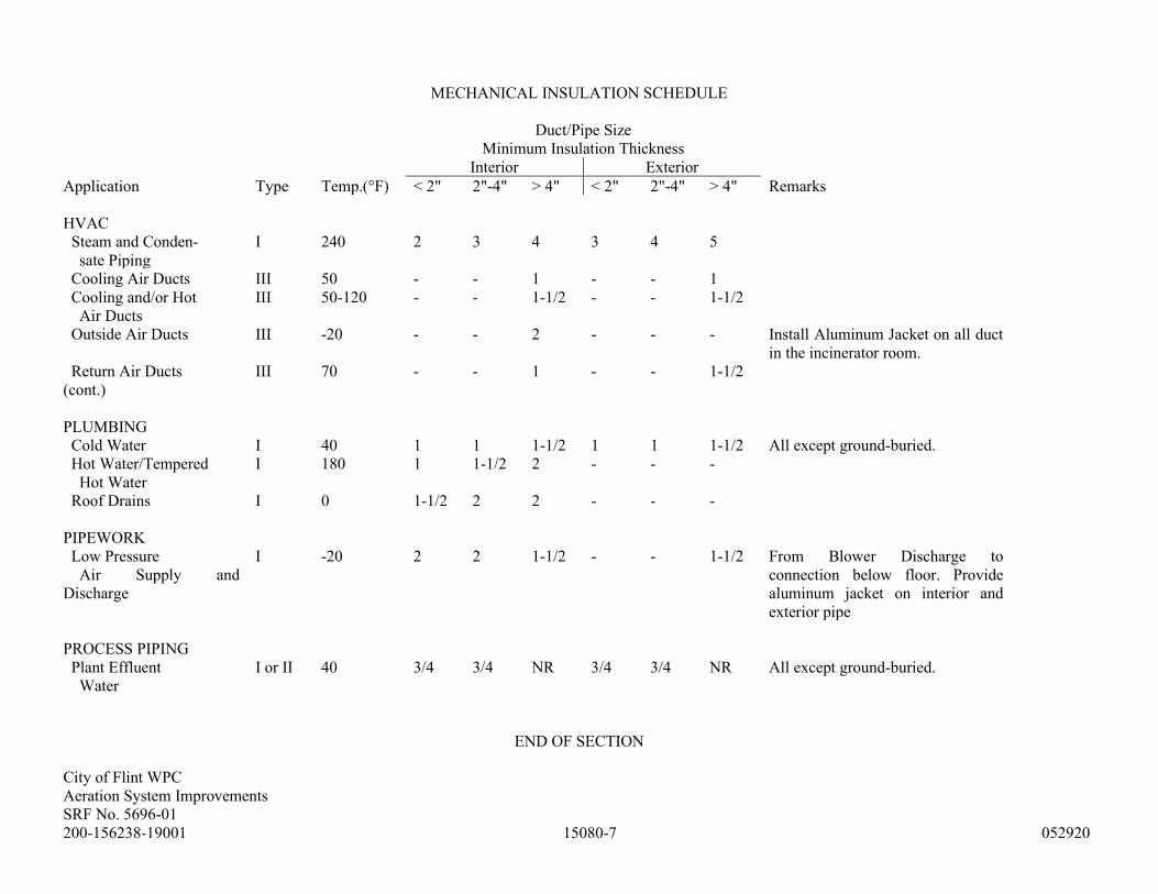
City of Flint WPC
Aeration System Improvements
SRF No. 5696-01
200-156238-19001 15080-7 052920
MECHANICAL INSULATION SCHEDULE
Duct/Pipe Size
Minimum Insulation Thickness
Interior Exterior
Application Type Temp.(°F) < 2" 2"-4" > 4" < 2" 2"-4" > 4" Remarks
HVAC
Steam and Conden-
sate Piping
I 240 2 3 4 3 4 5
Cooling Air Ducts III 50 - - 1 - - 1
Cooling and/or Hot
Air Ducts
III 50-120 - - 1-1/2 - - 1-1/2
Outside Air Ducts III -20 - - 2 - - - Install Aluminum Jacket on all duct
in the incinerator room.
Return Air Ducts III 70 - - 1 - - 1-1/2
(cont.)
PLUMBING
Cold Water I 40 1 1 1-1/2 1 1 1-1/2 All except ground-buried.
Hot Water/Tempered
Hot Water
I 180 1 1-1/2 2 - - -
Roof Drains I 0 1-1/2 2 2 - - -
PIPEWORK
Low Pressure
Air Supply and
Discharge
I -20 2 2 1-1/2 - - 1-1/2 From Blower Discharge to
connection below floor. Provide
aluminum jacket on interior and
exterior pipe
PROCESS PIPING
Plant Effluent
Water
I or II 40 3/4 3/4 NR 3/4 3/4 NR All except ground-buried.
END OF SECTION

City of Flint WPC
Aeration System Improvements
SRF No. 5696-01
200-156238-19001 15100-1 052920
SECTION 15100 - PRESSURE PROCESS PIPING
PART 1 - GENERAL
1.01 SUMMARY
A. Section includes the following:
1. Provide all labor, materials, and equipment necessary for fabrication and production of the
items specified in this Section and as shown on Drawings or listed on Schedule.
2. Unless otherwise noted on Drawings, or in this Section, pressure process piping 4 inches in
diameter and larger shall be part of this Work.
3. Dismantling of existing piping and supports, where required or shown or noted on Drawings;
piping connections to existing piping, structures, valves, gates, measuring devices, pumps and
other equipment, including equipment erected under other Contracts, are included in Work of
this Section. Piping shall contain necessary unions or companion flanges to allow ease of
equipment removal.
4. Complete all the demolition work and repair thereof to existing walls and slabs as required for
the installation of this Work including grouting of all sleeves and castings. Provide all necessary
joint and coupling materials, including bolts, nuts and gaskets, wall castings or sleeves, and
standard or special fittings. Furnish hangers, supports, anchors, blocking, harnesses, and other
necessary closure pipe sections and special fittings. Provide and secure in proper alignment, all
sleeve and casting openings in existing walls and slabs, including repair thereof.
5. Provide all shop-applied interior and exterior pipe linings and coatings. Provide plugs in open
ends of pipe, temporary bulkheads, protection of surface and subsurface improvements,
cleaning, painting, testing, and disinfection, as required to accomplish Work as specified and
shown on Drawings.
B. Products Installed But Not Furnished Under This Section: Install process valves, hydraulic gates,
flow meters, and other appurtenances which are furnished under other Sections and incorporated in
the piping systems as shown on Drawings and specified in this Section.
1. All pipe insulation shall be accomplished under Section 15080. Under this Section of Work, all
shop-applied surface coating shall be furnished as herein specified and pipe testing
accomplished prior to insulating.
2. Sewers are specified under Division 2.
3. All exposed pipe, field-applied finish painting preparation and repair of existing painted
surfaces shall be done under Division 9.
4. Floor and roof drain systems are specified under Section 15150.
C. Products Supplied But Not Installed Under This Section:
1. All piping, fittings, appurtenances, and shop-applied coatings shall be supplied as specified
under this Section.
2. The installation and testing of Water Distribution and Pumping Mains shall be performed as
specified in this Section.
1.02 SUBMITTALS
A. Shop Drawings: Submit in accordance with Section 01330, Shop Drawings covering the items
included under this Section. Shop Drawing submittals shall include:

City of Flint WPC
Aeration System Improvements
SRF No. 5696-01
200-156238-19001 15100-2 052920
1. Shop Drawings shall be fully dimensioned Drawings showing the piping in full detail with exact
locations, dimensions, and schedules of all pipe, fittings, hangers, supports, and appurtenances.
They shall be made in accordance with the general information shown on Drawing and special
information furnished by the several manufacturers of equipment. Where special fittings are
required, they shall be shown in large detail with all necessary dimensions.
2. Each pipe section, special fitting, casting, sleeve, and appurtenance shall be identified on
Drawings by its respective erection mark.
3. Design details of joints and joint restraint shall be submitted to ENGINEER for ENGINEER's
consideration and approval before ordering any pipe.
4. Product Data: Submit product data covering the items included under this Section.
B. Record Drawings: At Project closeout, submit record Drawings of installed products, in accordance
with requirements of Section 01770.
1.03 QUALITY ASSURANCE
A. All Work under this Section shall be done in accordance with standard practices as recommended by
manufacturer and AWWA.
B. Codes, Ordinances, and Standards: Manufacture, storage, and erection of equipment under this
Contract shall be in accordance with current ASA (ANSI), AWWA, and ASTM Standards.
Standards and Specifications referenced herein shall be the current published edition. The
manufacturer of the pipe and fittings shall furnish ENGINEER a certified statement that all pipe and
fittings furnished by manufacturer meet the material requirements and have been inspected and
tested in accordance with the applicable Specification and Standard.
1.04 DELIVERY, STORAGE, AND HANDLING
A. Disinfection compounds shall be stored in well-ventilated areas protected from moisture and fire.
B. Liquid Chlorine shall not be stored on Site except when more than one working day is required for
disinfection. Prior approval from ENGINEER and the local authorities is required for gas chlorine
storage.
C. Storage:
1. All pipe and related items installed under this Section shall be stored as recommended by
manufacturer.
2. CONTRACTOR shall take all actions necessary to protect all items installed under this Contract
including furnishing all special storage areas required by equipment manufacturers.
3. Pipe shall be stored on suitable timber skids free from contact with the ground. Gaskets shall be
stored in as cool, clean, and shaded a place as practical.
D. Handling:
1. All items installed under this Contract shall at all times be handled as recommended by
manufacturer and in such a manner as to avoid any damage.
2. All special handling equipment and temporary supports shall be provided by CONTRACTOR.
3. Items will be subject to inspection and approval upon delivery to the Site and after storage. No
cracked, broken, or damaged pipe shall be used.
4. In the event coatings are damaged, the damaged area shall be recoated with an approved coating
similar to that specified for that item.

City of Flint WPC
Aeration System Improvements
SRF No. 5696-01
200-156238-19001 15100-3 052920
5. Steel pipe shall be handled by means of rubber or fabric slings. No hooks shall be permitted to
come in contact with joint rings or be inserted in the ends of the pipe and fittings for any reason.
6. During handling, hauling, and storage of pipe, each piece shall be kept from contact with
adjacent pieces by means of wooden blocks or timbers.
1.05 PROJECT CONDITIONS
A. Existing Conditions: The Drawings are not intended to show every detail of construction or location
of piping or equipment. Where existing conditions make it necessary or advisable to change location
of piping or equipment, CONTRACTOR shall so inform ENGINEER for ENGINEER's approval.
PART 2 - PRODUCTS
2.01 MANUFACTURERS
A. Subject to compliance with specified requirements, manufacturers offering products which may be
incorporated in Work include:
1. Adapter Flange Coupling (AFC):
a. EBAA Iron Sales, Inc. (Series 2100 Megaflange).
b. Smith-Blair, Inc.
c. Uni-Flange Corp.
d. Victaulic Co.
2. Bolted Flexible Coupling (BFC):
a. Dresser Industries, Inc.
b. Smith-Blair, Inc.
3. Grooved Couplings (GC):
a. Victaulic.
b. Grinnell.
c. Anvil.
4. Plastic Pipe (PVC):
a. Spears.
b. Harvel.
c. JM Eagle.
5. High-Density Polyethylene Pipe (HDPE):
a. Performance Pipe.
b. KWH.
6. Equipment Connections:
a. Garlock.
b. Metra Flex.
c. Mercer Rubber Co.
d. Redflex.
e. Atlantic Metal Hose Co. (Vibra-flexor).
f. Allied Metal Hose Company.
g. Universal Oil Products Flexonics Division.
7. Hangers and Supports:
a. Grinnell.
b. Elcen.
8. Utility Markers:
a. ScotchMark mid-range markers, Model 1258, as manufactured by 3M Company.

City of Flint WPC
Aeration System Improvements
SRF No. 5696-01
200-156238-19001 15100-4 052920
b. 3M Marker Locator Model 1265.
9. Mechanical Joint-Retaining Glands, no substitution or "or equals" will be accepted:
a. "Megalug Series," as manufactured by EBAA Iron.
b. "Blockbuster 1400 Series," as manufactured by Uni-Flange (Ford Meter Box Co.).
10. Mechanical Sleeve Seals:
a. Thunderline Corp.
b. Calpico, Inc.
2.02 MATERIALS
A. Disinfection Products:
1. Liquid Chlorine shall not be allowed for this Project.
2. Sodium Hypochlorite shall meet the requirements of AWWA B300. Containers shall have an
expiration date marked at time of shipment to ensure that excessive deterioration has not
occurred.
3. Calcium Hypochlorite shall meet the requirements of AWWA B300.
2.03 PIPE JOINTS
A. All joint material and lubricants shall be furnished with the pipe, including all joint material required
for connection to equipment furnished under other Sections. All joint materials shall be assembled in
accordance with standard practice and manufacturer's recommendations. All equipment connections
shall be flanged, union, or grooved coupling so that equipment can be removed without disassembly
of the connecting piping.
B. Bolted Flexible Couplings (BFC): Bolted flexible couplings shall consist of a steel sleeve, with
centering bead removed, rubber gaskets, follower rings, and a full complement of nuts and bolts.
Couplings shall allow a deflection of approximately 4 degrees per joint.
1. Couplings shall have a minimum middle ring thickness and minimum length as follows:
Pipe Size (inches) Middle Ring Thickness Middle Ring Length
4 0.203-inch 5-inch
6 to 12 1/4-inch 5-inch
14 to 20 5/16-inch 7-inch
24 3/8-inch 7-inch
30 to 48 3/8-inch 10-inch
54 to 72 1/2-inch 10-inch
2. Couplings shall have a maximum gap between pipe ends as follows:
Sleeve Length Max. Gap Allowed
5-inch 1-inch
7-inch 2-inch
10-inch 3-inch
3. Couplings and accessories shall be galvanized and shall be shop coated with a sealer suitable for
subsequent field painting or coating.
4. Restraint rods shall be installed across coupling

City of Flint WPC
Aeration System Improvements
SRF No. 5696-01
200-156238-19001 15100-5 052920
C. Flanged Joints (FJ): Pipe flanges shall conform to American Standards: dimensions, ANSI B16.1 and
threads, ANSI B2.1. Flange faces except stainless steel shall be coated with a rust inhibitor
immediately after drilling.
1. Flanges for cast or ductile iron pipe and fittings shall be ductile iron and meet the requirements
of AWWA C115 (ANSI 21.15).
2. Flanges for steel plate pipe and fittings shall meet the requirements of AWWA C207 Standard
Steel Ring Flanges, Class B, except high service discharge piping as noted on Drawings or on
Schedule, shall be Class D.
3. Flanges for stainless steel pipe shall be fabricated from stainless steel flat plate of the same
composition as the pipe.
4. Flanges for stainless steel tubing shall be constructed using standard steel angle face rings (Van
Stone Connection) and galvanized carbon steel backup flanges.
5. Flanged joints shall be made up with full-face 1/8-inch rubber gaskets. Gaskets for gas lines
shall be neoprene and asbestos.
6. Flanges shall be firmly bolted with machine, stud or tap bolts of the proper size and number
meeting the requirements of ASTM A 307, Grade B. Joints made with bolts or bolt studs shall
have a nut on each side. Bolt projection through nuts shall be equal, and where studs are used,
bolt projection on each side of the flange shall be equal.
7. All nuts and bolts shall be cadmium plated or hot-dip galvanized except on stainless steel
flanges shall be 316L stainless steel.
8. Flange connections to all flexible connectors and expansion joints shall have a lock washer
under all nut and bolt heads, 2 control rods across each joint and steel retainer rings at each
flange. All steel materials shall be galvanized.
9. Flange joints shall not be used on ground-buried pipe.
D. Grooved Couplings (GC): Provide rigid grooved couplings where shown or noted on Drawings or
noted on Pipe Schedule. Flexible type shall only be used in applications approved by ENGINEER.
1. Grooved couplings and fittings may be used in lieu of flanged joints.
2. Couplings shall conform to AWWA Standard C606.
3. Gaskets shall be molded or extruded of an elastomer that is recommended by coupling
manufacturer and that will satisfy the end use. End use includes consideration for pipe material
and material being transmitted by the pipe.
4. Generally, ductile iron pipe gaskets shall be halogenated Butyl compound, and steel pipe shall
be an ethylene, propylene, diene-monomer (EPDM) compound.
5. Shop Drawings submitted shall identify the gasket material, pipe material, and material being
transmitted in the pipe.
6. Cast iron or ductile iron fittings shall conform to the requirements of ANSI Specifications
A21.10 or AWWA C110 with end preparation of a radius cut groove configuration.
7. Standard weight steel pipe or better may be cut grooved in accordance with manufacturer's
standard groove dimensions. Where pipe is less than or standard weight, a ring shall be welded
to steel pipe to form the necessary shoulder for the joint, or the pipe may be roll-grooved in
accordance with manufacturer's recommendation for roll-grooving pipe as approved by
ENGINEER.
8. Ductile iron pipe in sizes 4-inch to 24-inch shall be radius cut grooved in accordance with
manufacturer's specifications.
City of Flint WPC
Aeration System Improvements
SRF No. 5696-01
200-156238-19001 15100-6 052920
E. Mechanical Joints (MJ): Mechanical joint shall conform to ANSI A21.10 and AWWA C110, or
ANSI A21.11.
1. Each joint shall be complete with rubber gasket, cast iron gland and a full complement of high-
strength, low-alloy steel bolts and nuts.
2. All mechanical joints are to be restrained in accordance with the paragraph on joint restraints.
F. Screwed Joints (SJ): Screwed joints in steel plate, galvanized steel, or black steel pipe shall conform
to American Standards: dimensions, ANSI B16.3; threads, ANSI B2.1. The ends of pipe shall be
reamed and all burrs and cuttings shall be removed. Joints shall be sealed with Teflon thread tape or
an approved compound.
G. Welded Joint (WJ): Butt-welded joints shall be used whenever shown or noted on Drawings.
Welding shall comply with the current AWWA Standard C206. Lap-welded joints may be used if
approved by ENGINEER.
H. Adapter Flange Coupling (AFC): Adapter flange couplings for steel or ductile iron pipe shall be
provided where shown on Drawings.
1. The coupling shall be designed to meet the test requirements of ANSI B16.1, 125-pound
flanges.
2. The coupling shall be designed to handle a 525 psi hydrostatic test and 175 psi working pressure
at temperatures of -20 to 150 degrees Fahrenheit without leaking or requiring additional
restraint.
3. The coupling shall consist of a standard flange drilling (ANSI B16.1); a standard mechanical
joint material (ANSI A21.11 or AWWA C111); and standard retainer gland construction
(AISI 4140 steel setscrews, galvanized with ductile iron body ASTM A 536).
2.04 PIPING
A. Black Steel Pipe (BSP): Black steel pipe shall meet the requirements of ASTM A 53, Schedule 80.
1. Fittings: Fittings shall be wrought carbon steel manufactured in accordance with
ANSI/ASTM A 234, and welded conforming to ANSI B16.9, B16.11, B16.28, MSS SP-79,
ASTM A 234, WPA-Grade, equal in thickness to the pipe.
2. Joints: Black steel pipe joints shall be welded with flange connections where required for
connection to equipment in accordance with the paragraph on "Pipe Joints," as shown or noted
on Drawings, listed on Schedule, and approved by ENGINEER.
3. Coating and Lining: Ground-buried black steel pipe and fittings shall be coated on the outside
with a cold-applied wax coating.
4. All 6 inch to 12 inch exposed piping for Aeration supply piping shall be ASTM A53 Schedule
20 with Buttwelding Fittings.
5. All 14 inch to 66 inch exposed piping for Aeration supply piping shall be ASTM A53 Schedule
10 with Buttwelding Fittings.
B. Ductile Iron Pipe (DIP): Buried ductile iron pipe shall be either the Pressure Class indicated on Bid
Form or on Schedule. If no classification is indicated, pipe shall be the highest Standard Pressure
Class available. Ductile iron pipe shall be manufactured in accordance with AWWA C151
(ANSI A21.51). Pipe placed in buildings to be joined by flanges or grooved couplings for the pipe
size shown shall have a minimum thickness of Special Thickness Class 53. Each pipe run shall be of
the same class. Pipe sizes indicated are inside diameter (I.D.).
1. Fittings for flanged ductile iron pipe shall be ductile iron or cast iron and shall meet the
requirements of AWWA C110 (ANSI A21.10) and for 54-inch and larger sized shall meet the

City of Flint WPC
Aeration System Improvements
SRF No. 5696-01
200-156238-19001 15100-7 052920
requirements of AWWA C153 (ANSI A21.53). Fittings for mechanical joint ductile iron pipe
shall meet the requirements AWWA C110 (ANSI A21.53) Ductile iron fittings shall be rated
for 350 psi, pipe sizes 24-inch diameter and less and 250 psi for pipe sizes over 24-inch
diameter, except that ductile iron flanged fittings shall be rated for 250 psi for all pipe
diameters.
2. Cast iron fittings shall be rated for 250 psi, pipe sizes 12-inch diameter and less and 150 psi for
pipe sizes over 12-inch diameter.
3. Ductile iron joints shall be mechanical, bolted flexible coupling, and push-on, as specified under
Pipe Joints, as shown or noted on Drawings, listed on Schedule, and approved by ENGINEER.
Joints shall meet the requirements of AWWA C111 (ANSI A21.11). All joint materials shall be
furnished with the pipe.
4. Coatings and Linings: Ductile iron pipe and fittings to be ground buried shall be coated by
manufacturer on the outside with an asphaltic coating 1 mil thick, in accordance with
AWWA C151 and C110 (ANSI A21.51) and cement lined, standard thickness, in accordance
with AWWA C104/ANSI 21.4. The pipe shall be supplied with and wrapped in polyethylene
encasement in accordance with AWWA C105 (ANSI 21.5) and shall be installed following
Method "A."
5. Exposed pipe and fittings shall be coated by manufacturer on the outside with a universal rust-
inhibitive primer 2 mils minimum dry thickness, and cement lined, standard thickness, in
accordance with AWWA C104/ANSI 21.4.
C. Galvanized Steel Pipe (GSP): Steel pipe shall meet the requirements of ASTM A 53 standard weight
class.
1. Screwed fittings shall be 150-pound malleable iron galvanized for field installation and welded
fittings ANSI B16.9, ASTM A 234, WPA Grade, equal in thickness to the pipe for factory
fabrication.
2. Galvanized steel pipe joints shall be flanged, shop welded, grooved coupling, bolted flexible
coupling or screwed in accordance with the paragraphs under "Pipe Joints," as shown or noted
on Drawings, listed on Schedule, and approved by ENGINEER.
3. Coating and lining shall be galvanized after fabrication in accordance with ASTM A 153. No
field galvanizing will be allowed.
D. Plastic Pipe (PVC): Plastic pipe shall be designed, fabricated, and installed in accordance with these
Specifications and as shown or noted on Drawings and listed on Schedule.
1. Plastic pipe shall meet the requirements of ASTM D 1785 (PVC) Schedule 80, socket end
ASTM D 2467.
2. Pipe sizes indicated are I.D.
3. Plastic pipe fittings shall meet the same requirements as the pipe and connections shall be
socket type ASTM D 2467.
4. All plastic pipe joints shall be socket type in accordance with the paragraph on "Socket Type
Joints."
5. Installation shall be in accordance with the paragraph on "Pipe Installation." In addition, the
recommendations of ASTM Committee D 20 on Plastics relating to the installation of flexible
thermoplastic sewer pipe shall be followed. Hanger spacing shall be as shown or noted on
Drawings and meet manufacturer's recommendations as approved by ENGINEER.
E. Stainless Steel Pipe (SSP): Stainless steel pipe shall be designed and fabricated in accordance with
the ASTM Standards A 312 and A 409, and as shown on Drawings.
1. The pipe and fittings and all appurtenant supports specified shall be made from 304 L stainless
steel with a minimum No. 1 mil finish and a maximum carbon content of 0.035 percent.

City of Flint WPC
Aeration System Improvements
SRF No. 5696-01
200-156238-19001 15100-8 052920
2. Pipe schedule shall be as shown on Drawings or on Pipe Schedule.
3. Fittings shall be made to ASTM A 403 standards, to MSS SP-43 dimensional tolerances, and
shall be equal in wall thickness to, and meet the conditions of, the pipe.
4. Special fittings shall meet the requirements of the pipe and shall be as shown on Drawings.
5. All welding shall be performed in shop and be accomplished using inert gas shielded-arc
method. Where consumable electrode or filler wire is used, they shall be the same material as
the parent metal. Butt welds shall have full penetration to the interior surface and gas shielding
provided to the interior and exterior of the joint.
6. All interior weld finishes shall equal the smoothness of a minimum No. 1 mil sheet finish. The
weld bead shall be smooth evenly distributed with an interior projection not exceeding 1/16 inch
beyond the I.D. of the pipe or fitting. All unevenness shall be finely ground to meet the above
requirements. Coarse grinding shall not be permitted.
7. All exterior weld finishes shall be wire brushed with stainless steel brushes used only on
stainless steel. The joints shall then be cleaned of all discoloration, and deposits left during
welding shall be removed by pickling.
F. Stainless Steel Tubing (SST): Stainless steel tubing shall be designed and fabricated in accordance
with ASTM Standard A 778 and as shown on Drawings.
1. The pipe and fittings and all appurtenant supports specified shall be made from 304 L stainless
steel with a maximum carbon content of 0.03 percent.
2. Finish shall be No. 2 mil finish or better.
3. Tubing Thicknesses: Nominal pipe size indicated for pipe less than 14-inch shall be iron pipe
size (IPS), and pipe 14-inch and larger shall be outside diameter (O.D.). Pipe shall be fabricated
in the thickness as given in the following Schedule:
Tube O.D. Wall Thickness
8-inch and less 14 gauge
10-inch to 18-inch 12 gauge
20-inch and greater 10 gauge
4. Fittings shall be made to ASTM Standard A 774, MSS SP-43 dimensional tolerances and shall
be equal in wall thickness to, and meet the conditions of, the pipe.
5. Special fittings shall meet the requirements of the pipe and shall be as shown on Drawings.
6. All welding shall be performed in shop and accomplished using inert gas shielded-arc method.
Filler material shall be extra low carbon and appropriate for use with the base metal. Butt welds
shall have full penetration to the interior surface and gas shielding provided to the interior and
exterior of the joint.
7. All interior weld finishes shall equal the smoothness of a minimum No. 2 mil sheet finish. The
weld bead shall be smooth and evenly distributed with an interior projection not exceeding
1/16-inch beyond the I.D. of the pipe or fitting.
8. All exterior weld finishes shall be wire brushed with stainless steel brushes.
9. Finished pipe and fittings shall be immersion pickled in 6 to 10 percent nitric acid and 3 to
5 percent hydrofluoric acid prior to shipment.
10. SST joints shall be flanged, shop welded, bolted flexible coupling or screwed, in accordance
with the paragraphs under "Pipe Joints," as shown or noted on Drawings, listed on Schedule,
and approved by ENGINEER. Field welded joints shall not be allowed.
City of Flint WPC
Aeration System Improvements
SRF No. 5696-01
200-156238-19001 15100-9 052920
G. Polyvinyl Chloride Pressure Pipe (PVCP):
1. PVCP pipe shall be manufactured of PVC resin compounds Class 12454 A or B conforming to
ASTM D 1784 in accordance with ASTM D 2241. Unless otherwise indicated on Schedule or
Bid Form, all PVCP pipe shall have a pressure rating of 200 psi (SDR 21).
2. If used for potable water service, PVCP shall meet the requirements of AWWA C900 & 905,
ANSI/NSF 14 and ANSI/NSF 61.
3. Fittings shall be cast or ductile iron of comparable class, provided with special gaskets for SDR
size pipe.
4. Joints shall be bell and spigot type with a flexible elastomeric gasket conforming to
ASTM D 3139. Joints shall be made using lubricant as supplied and as directed by
manufacturer. If it is necessary to field cut a standard length of pipe, the new spigot end shall be
prepared as recommended by pipe manufacturer.
5. After delivery, PVCP pipe shall be stored on a flat surface so that the barrel is evenly supported.
Pipe shall not be stored in piles higher than 4 feet. If the pipe is to be stored for an extended
period of time, it shall be covered with an opaque material so it is protected from the sun's rays
and the bells shall be inverted in alternate rows so they are not supporting the direct load of the
pipe. Deflection of any particular amount of PVCP pipe shall not exceed 5 percent.
2.05 WALL AND SLAB SLEEVES AND CASTING
A. At all points where pipes must pass through the walls, floors, or slabs of structures, CONTRACTOR
shall furnish and install suitable sleeves or wall castings. Unless otherwise shown or permitted, the
space between the pipe and the sleeve shall be sealed at the inside and outside wall faces on walls
exposed to earth or water/sewage, at one face of other walls, and at the top surface of floors and slabs
with a rubber link seal.
B. In general, the wall sleeve or castings shall be of the same material as the pipe. Iron pipe
wall castings, wall pipe, transition sleeves, and solid sleeves shall meet the requirements of
AWWA Specifications C100 and shall be of the lightest class conforming to the pressure rating of
the pipelines which they connect, but in no case shall be lighter than Class B.
C. Steel sleeves and wall pipe shall not be painted in areas to be embedded in the concrete. Under this
Section, all loose rust, scale, grease, or oil shall be removed prior to pouring of the concrete.
D. Where watertightness is essential and at other locations where indicated on Drawings, wall castings,
and sleeves shall be provided with an intermediate flange located approximately at the center of the
wall.
E. Sleeves and castings at the point of manufacture shall be coated on the inside with a universal rust-
inhibitive primer 1.5 to 2.0 mils minimum dry thickness.
F. Rubber link seal shall be identical rubber links interconnected with bolts and elongated nuts and
washers. The sealing element shall be made of synthetic rubber material especially compounded to
resist aging, ozone, sunlight, and chemical action. Bolts and metal parts shall be made of galvanized
or cadmium-plated steel to resist corrosion. Rubber link seal joints shall be submitted to ENGINEER
for approval.

City of Flint WPC
Aeration System Improvements
SRF No. 5696-01
200-156238-19001 15100-10 052920
2.06 EQUIPMENT CONNECTIONS
A. The connecting piping to pumps and other equipment shall be supported independently of the pump
or equipment so as to avoid any strain on the pump or equipment.
B. All equipment connections shall be flanged or have unions to facilitate removal of the equipment.
C. Piping to vibrating equipment shall contain control-rodded, retainer ringed flanges, flexible spool-
type expansion joint of duct and chlorobutyl or Buna-N material as shown or noted on Drawings.
D. All carbon steel shall be galvanized.
2.07 JOINT RESTRAINT
A. Where water or air pressure exerts a disjoining force, at all pipe deflections over 20 degrees, and all
tees and dead ends, joints shall be restrained, tied, or harnessed in a manner approved by
ENGINEER.
B. The restraint shall be applied to joints in each direction from the deflection an adequate distance to
resist the axial thrust of the test pressure as shown on Pipe Restraint Schedule on Drawings. Fire
hydrants shall be restrained from the main line to the hydrant. Details of all proposed joint restraint,
showing the type and locations, shall be submitted to ENGINEER for approval. Concrete thrust
blocks will not be permitted except where noted. All pipe and fitting restrained joints shall be rated
for a minimum of 250 psi.
C. For unit price items, joint restraint shall be considered as included in the prices Bid for the type and
size of pipe listed on Bid Form.
D. Acceptable methods of joint restraint are as follows:
1. Ductile Iron Pipe: Mechanical joint pipe with EBAA Iron "Megalug Series," or Uni-Flange
Block Buster 1400 retainers, shall be used when shown on Drawings. Megalugs or Uni-Flange
Block Buster 1400 retainers may also be used to restrain joints for unanticipated deflection
points, or where connections require a mechanical joint. Restrained joint glands and hardware
shall have surfaces factory prepared and protected with a corrosion resistant coating system.
Glands shall have a polyester or epoxy fusion bonded coating. Wedges, nuts and bolts shall
have two coats of a heat cured blue fluoropolymer coating or alternatively made of stainless
steel. No other manufacturers or types of mechanical joint-retaining glands will be accepted.
Push-on joint pipe shall be restrained with American Lok-Ring, Flex-ring or Fast-Grip Gaskets,
U.S. Pipe TR Flex, or equal.
2. Steel Pipe: Studs and lugs AWWA Manual MII (studs galvanized).
2.08 JOINT HARNESSING
A. Pipe and fittings that require harnessing shall be provided with standard lugs ASTM A 283, Grade B,
or A 285, Grade C, or equal, meeting the requirements of AWWA Specification C111 or
AWWA Manual M11, unless otherwise noted.
B. Harness tie rods and nuts shall be mild steel meeting the requirements of ASTM A 193, Grade B7, or
A 307, Grade B, or equal with American Standard threads. The nuts shall seat on steel plate washers.
The rod, washers, and nuts shall be hot-dip galvanized ASTM A 153.
City of Flint WPC
Aeration System Improvements
SRF No. 5696-01
200-156238-19001 15100-11 052920
2.09 HANGERS AND SUPPORTS
A. Hangers and supports shall include all hanging and supporting devices of metallic construction
shown, specified, or required for piping, apparatus, and equipment installed under this Section. All
supports and parts shall conform to the latest requirements of ANSI B31.1, except as supplemented
or modified by the requirements of this Specification or as detailed on Drawings. Materials shall be
stainless steel.
B. Hangers and supports shall be adequate to maintain the pipelines, apparatus, and equipment in proper
position and alignment under all operating conditions with due allowance for expansion and
contraction, and shall have springs where necessary. Hangers and supports shall be of standard
design where possible and be best suited for the service required, as approved by ENGINEER.
Supporting devices shall be designed in accordance with the best practice and shall not be
unnecessarily heavy. Sufficient hangers and supports shall be installed to provide a working safety
factor of not less than 5 for each hanger. Hangers shall have a minimum spacing in accordance with
ANSI B31.1. Point loading hangers are not acceptable. Hangers shall be sling or saddle type.
C. Wherever possible, pipe attachments for horizontal piping shall be pipe clamp, and structural
attachments shall be beam clamps. All rigid hangers shall provide a means of vertical adjustment
after erection. Generally, hangers shall be sized for supporting the pipe, excluding insulation. Proper
pipe protection saddles shall be installed on pipes that are covered with insulation where hangers and
supports are outside the insulation. Overhead hangers shall be supported by threaded rods properly
fastened in place by suitable screws, clamps, inserts or bolts, or by welding. Saddle stands shall be of
the adjustable type. Each stand shall consist of a length of steel pipe fitted at the base with a standard
threaded flange and at the top with an adjustable saddle or roll. The base flange shall be bolted to the
floor, foundation, or concrete base.
D. Anchors shall be furnished and installed where specified, shown, or required for holding the
pipelines and equipment in position or alignment. Anchors shall be designed for rigid fastening to
the structures, either directly or through brackets. The design of all anchors shall be subject to
approval by ENGINEER. Materials shall be stainless steel. Inserts for concrete shall be stainless
steel and shall be installed in the concrete structures where required for fastening supporting devices.
They shall be designed to permit the rods to be adjusted horizontally in one place and to lock the rod
nut or head automatically. Inserts shall be recessed near the upper flange to receive reinforcing rods.
Inserts shall be so designed that they may be held in position during concrete pouring operations.
Inserts shall be designed to carry safely the maximum load that can be imposed by the rod that they
engage.
E. Concrete supports shall be placed wherever shown or required under Division 3. Equipment shall be
supported in accordance with manufacturer's recommendations.
2.10 CLEANOUTS
A. Cleanouts shall be provided where shown or specified. Cleanout openings for pipe 8 inches or larger
in diameter shall be not less than 6 inches in diameter (unless otherwise noted on Drawings).
B. Cleanout openings for pipe 6 inches and smaller shall be of the same diameter as the pipe.

City of Flint WPC
Aeration System Improvements
SRF No. 5696-01
200-156238-19001 15100-12 052920
C. Cleanout covers shall be standard 125-pound blind flanges, where conformation is required with the
inside curvature of the pipeline, in which case the covers shall be flanged of proper shape with
standard flange drilling.
D. Covers shall be fastened by means of galvanized steel studs and nuts and shall be drilled and tapped
for a 1-1/2-inch pipe connection. A 1-1/2-inch galvanized steel plug shall be furnished. The flange or
conformed plugs shall be provided with a dowel or other suitable means to ensure proper setting.
2.11 TAPS AND PLUGS
A. Where indicated or required, pipe or fittings shall be tapped to receive small or special fittings under
this or other headings of the Work. Required taps shall be provided as part of this Work.
B. All taps shall be temporarily plugged at point of fabrication.
2.12 SOURCE QUALITY CONTROL
A. Tests, Inspections:
1. All pipe and fittings delivered to the Project shall be accompanied by certification papers
showing that the pipe and fittings have been tested in accordance with the applicable
Specifications and that pipe and fittings meet the Specifications for this Project. All pipe and
fittings will be inspected upon delivery to the Site by ENGINEER or OWNER's Representative.
No cracked, broken, or damaged pipe or fittings will be allowed in this Work.
2. Ductile Iron Pipe:
a. Each pipe shall be hydrostatically tested to 500 psi at the point of manufacture.
b. The class of nominal thickness, net weight without lining, and casting period shall be
clearly marked on each length of pipe. Additionally, the manufacturer's mark, county
where cast, year in which the pipe was produced, and the letters "DI" or "ductile" shall be
cast or stamped on the pipe.
c. Where required, other designation marks shall be painted on the pipe or fittings to indicate
correct location in the pipeline in conformity to a detailed layout plan.
PART 3 - EXECUTION
3.01 ERECTION
A. Equipment provided under this Section shall be fabricated, assembled, erected, and placed in proper
operation condition in full conformity with detail Drawings, specifications, engineering data,
instructions, and recommendations of equipment manufacturer approved by ENGINEER.
3.02 INSTALLATION
A. Laying and Erecting Pipe: Pipe shall be installed as recommended by manufacturers or by the
applicable AWWA installation manual or specification.
1. Pipe shall be carefully laid to line and grade as shown on Drawings. Care shall be taken to keep
the interior of the pipe clean and free from dirt and other foreign materials.
2. Bulkheads or other means shall be used at the open ends of the pipe for this purpose. At the end
of each day's work, ground-buried pipe shall have its working end bulkheaded.

City of Flint WPC
Aeration System Improvements
SRF No. 5696-01
200-156238-19001 15100-13 052920
3. Ground-buried ductile iron pipe shall be wrapped with polyethylene encasement in accordance
with AWWA C105 (ANSI 21.5) following Method "A."
B. Field Cutting Piping: The spigot ends of all pipe lengths, which have been cut in the field, shall be
ground to a smooth surface and painted with 2 coats of asphaltum metal protective paint.
C. Bolted Flexible Couplings (BFC): All bolted flexible couplings shall be harnessed with tie bolts or
studs across the joint, design based on test pressures.
1. On cast iron or ductile iron pipe, tie bolts shall be installed between flanges across the coupling
unless otherwise noted on Drawings or approved by ENGINEER.
2. Piping of other materials shall be furnished with lugs. The number and size of the bolts and
studs and other details of the harnessed joint shall be submitted to ENGINEER for review.
3. Tie bolts or studs shall be galvanized.
D. Concrete Cradle: Pipework shall be placed on Class "C" concrete cradle in locations and according
to details shown on Drawings.
E. Bedding: Where the subgrade is disturbed during excavation, the space shall be refilled with bedding
material solidly tamped to form a firm foundation for the pipe.
1. At least the bottom quarter of the pipe shall be laid on a sand or pea gravel bedding, except that
the bedding shall be exclusively pea gravel for pipe 48 inches and larger in diameter. Bedding
shall be provided as specified under Division 2.
F. Joints: All joints shall be assembled in accordance with that described in the "Pipe Joints" Article.
G. Connections to Existing Facilities:
1. CONTRACTOR shall furnish all labor and materials required for the connection of piping
under this Contract to existing structures as called for on Drawings.
2. Where breaking holes for connections to existing structures, care shall be taken to prevent
debris from entering.
3. After installation of the pipe, the structure shall be pointed up around the pipe, both on the
inside and outside so that it is restored to a watertight condition.
H. Connections to Existing Mains: Where shown on Drawings, connections of existing main to the new
mains shall be done only after the new mains are shown to be disinfected by the results of the
bacteriological analysis. Care should be taken to prevent debris from entering water main.
3.03 PIPE LOCATING SYSTEMS
A. Utility Markers: All plastic pipe pumping mains shall have an electronic marker system furnished
and installed complete with marker locator.
1. Markers shall be installed in a horizontal position 3 to 4 feet below the ground surface.
2. A marker shall be placed over every buried tee, bend, or saddle fitting, at intervals no greater
than 100 feet along pumping mains and where directed by ENGINEER.
3. Holes shall be excavated over bored or directionally drilled pumping main for placement of
markers.

City of Flint WPC
Aeration System Improvements
SRF No. 5696-01
200-156238-19001 15100-14 052920
3.04 REPAIR
A. Repair of all damaged interior pipe coatings, ground-buried exterior pipe coatings and galvanized
coatings shall be under this Section. Repair of exposed painted pipe shall be as specified under
Section 09900.
B. For field-welded joints, both inside and outside, coatings shall be left off for a distance of 6 inches
from each end. These areas shall be shop primed. After completing the welded joint and under this
Section, the interior of all joints and exterior of ground-buried pipe shall be thoroughly cleaned,
primed, and given field coating of the same material as specified for the pipe. Coating shall meet the
requirements of AWWA C203 or AWWA C210, as approved by ENGINEER. Exposed field-welded
joints shall be cleaned under this Section to remove slag and scale, and then shall be finish cleaned,
primed and painted under Division 9.
C. Damaged linings, coatings, and wrapping shall be repaired under this Section and, if possible, before
pipe is laid.
1. Surfaces shall be thoroughly cleaned, dried, and free of old materials.
2. They shall then be given a field coating of the same material as specified for the pipe.
3. Coating shall meet the requirements of AWWA C203, AWWA C210, or AWWA C602 as
approved by ENGINEER.
4. All other pipe coatings and linings shall be as stated in "Piping" Article.
3.05 AERATION PIPING REPAIR
A. The existing portions of the aeration piping in the WPC galleries and tanks have leaks. As part of
this project those leaks shall be repairs.
1. ENGINEER and OWNER shall determine leaks that shall be repaired.
2. The repair cost shall be based on the Unit Price Adjustment Table in the Bid Form and the
Agreement. The table provides a range for pipe diameter sizes.
B. Repair Approach
1. Leaks at Gaskets – aeration pipe leaks at gaskets shall be addressed by disassembling the pipe
joint and replacing the existing gasket. The joint shall then be reassembled using new bolt
hardware.
2. Leaks at Wall Penetrations – aeration pipe leaks at wall penetrations shall be reviewed to
determine if the leak is at the joint between pipes or in the pipe wall material at the wall
penetration. If the leak is at the joint the pipe shall be dissembled and repaired as indicated in
prior section. If the leak is in the pipe wall material the existing wall sleeve shall be removed
and a new sleeve shall be set in the wall. A new portion of pipe shall be installed through the
wall and link seal shall be installed between pipe and wall sleeve.
3. Leaks in Pipe Wall material – If the aeration pipe leaks are determined to be in the pipe wall the
leak shall be corrected by welding a new portion of steel over the existing pipe surface. The
patch material shall match the existing pipe wall thickeness and shall extend 6-inch in all
direction beyond the deteriorated portion of the pipe. The pipe surface shall be cleaned to
determine the extents of the repair. After patch is installed the portion of the pipe shall be
repainted.
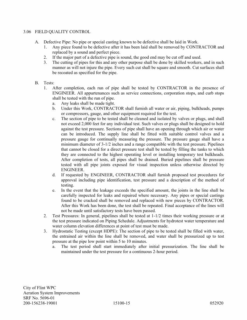
City of Flint WPC
Aeration System Improvements
SRF No. 5696-01
200-156238-19001 15100-15 052920
3.06 FIELD QUALITY CONTROL
A. Defective Pipe: No pipe or special casting known to be defective shall be laid in Work.
1. Any piece found to be defective after it has been laid shall be removed by CONTRACTOR and
replaced by a sound and perfect piece.
2. If the major part of a defective pipe is sound, the good end may be cut off and used.
3. The cutting of pipes for this and any other purpose shall be done by skilled workers, and in such
manner as will not injure the pipe. Every such cut shall be square and smooth. Cut surfaces shall
be recoated as specified for the pipe.
B. Tests:
1. After completion, each run of pipe shall be tested by CONTRACTOR in the presence of
ENGINEER. All appurtenances such as service connections, corporation stops, and curb stops
shall be tested with the run of pipe.
a. Any leaks shall be made tight.
b. Under this Work, CONTRACTOR shall furnish all water or air, piping, bulkheads, pumps
or compressors, gauge, and other equipment required for the test.
c. The section of pipe to be tested shall be cleaned and isolated by valves or plugs, and shall
not exceed 2,000 feet for any individual test. Such valves or plugs shall be designed to hold
against the test pressure. Sections of pipe shall have an opening through which air or water
can be introduced. The supply line shall be fitted with suitable control valves and a
pressure gauge for continually measuring the pressure. The pressure gauge shall have a
minimum diameter of 3-1/2 inches and a range compatible with the test pressure. Pipelines
that cannot be closed for a direct pressure test shall be tested by filling the tanks to which
they are connected to the highest operating level or installing temporary test bulkheads.
After completion of tests, all pipes shall be drained. Buried pipelines shall be pressure
tested with all pipe joints exposed for visual inspection unless otherwise directed by
ENGINEER.
d. If requested by ENGINEER, CONTRACTOR shall furnish proposed test procedures for
approval including pipe identification, test pressure and a description of the method of
testing.
e. In the event that the leakage exceeds the specified amount, the joints in the line shall be
carefully inspected for leaks and repaired where necessary. Any pipes or special castings
found to be cracked shall be removed and replaced with new pieces by CONTRACTOR.
After this Work has been done, the test shall be repeated. Final acceptance of the lines will
not be made until satisfactory tests have been passed.
2. Test Pressures: In general, pipelines shall be tested at 1-1/2 times their working pressure or at
the test pressure indicated on Piping Schedule. Adjustments for hydrotest water temperature and
water column elevation differences at point of test must be made.
3. Hydrostatic Testing (except HDPE): The section of pipe to be tested shall be filled with water,
the entrained air within the line shall be removed, and water shall be pressurized up to test
pressure at the pipe low point within 5 to 10 minutes.
a. The test period shall start immediately after initial pressurization. The line shall be
maintained under the test pressure for a continuous 2-hour period.

City of Flint WPC
Aeration System Improvements
SRF No. 5696-01
200-156238-19001 15100-16 052920
b. The section of pipe to be tested shall hold the test pressure with no more than a 5 percent
loss in pressure over the test period or the leakage per hour under the conditions of test
shall not exceed values determined by the following equation:
148,000
PSD = L
where L = allowable leakage per hour (gallons)
S = length of pipe in test (feet)
D = nominal diameter of pipe (inches)
P = average test pressure (psi, gauge)
c. Piping with flanged, grooved coupling, screwed, socket type, and welded joints shall be
completely tight at the designated test pressure.
d. The test pressure shall not vary by more than 5 psi throughout the entire test period.
4. Pneumatic Testing: The section of pipe to be tested shall be filled with air and pumped up to test
pressure.
a. Sufficient time shall be allowed for the air pressures to stabilize at the test pressure. After
the stabilization period, the air control valve shall be closed and the test period started. The
section of pipe shall be maintained under the test pressure for a continuous 4-hour period
with no more than a 10 percent loss in pressure over the entire test period.
b. Pneumatic testing of HDPE pipe shall not be allowed.
5. Each valve assembly shall be tested by CONTRACTOR; the test shall consist of opening and
closing the valve.
6. Each hydrant assembly shall be tested by CONTRACTOR; the test shall consist of flushing the
hydrant for a minimum of ten minutes. During the test period the 6-inch gate valve shall be
closed and opened. CONTRACTOR shall furnish necessary hoses for the disposal of OWNER-
furnished water.
END OF SECTION

City of Flint WPC
Aeration System Improvements
SRF No. 5696-01
200-156238-19001 15105-1 052920
SECTION 15105 - BASIC PLUMBING PIPING MATERIALS AND METHODS
PART 1 - GENERAL
1.01 SUMMARY
A. Section Includes: Piping materials and installation methods common to more than one Section of
Division 15 and includes pipe, fitting and joining materials, piping specialties, and basic piping
installation instructions.
B. All fastening hardware shall be 304 stainless steel.
1.02 SUBMITTALS
A. Shop Drawings: Submit in accordance with Sections 01330 and 15050, Shop Drawings covering the
items included under this Section. Shop Drawing submittals shall include:
1. Submit product data on the following items:
a. Escutcheons.
b. Dielectric Unions and Fittings.
c. Mechanical Sleeve Seals.
B. Quality Control Submittals: Submit welders' certificates specified in Quality Assurance below.
1.03 QUALITY ASSURANCE
A. Welder's Qualifications: All welders shall be qualified in accordance with ASME Boiler and
Pressure Vessel Code, Section IX, Welding and Brazing Qualifications.
1. Welding procedures and testing shall comply with ANSI Standard B31.1.0, Standard Code for
Pressure Piping, Power Piping, and The American Welding Society, Welding Handbook.
B. Soldering and Brazing procedures shall conform to ANSI B9.1 Standard Safety Code for Mechanical
Refrigeration.
1.04 DELIVERY, STORAGE, AND HANDLING
A. Provide factory-applied plastic end-caps on each length of pipe and tube except for concrete,
corrugated metal, hub-and-spigot, and clay pipe. Maintain end-caps through shipping, storage, and
handling to prevent pipe-end damage and prevent entrance of dirt, debris, and moisture.
B. Protect stored pipes and tubes. Elevate above grade and enclose with durable, waterproof wrapping.
When stored inside, do not exceed structural capacity of the floor.
C. Protect flanges, fittings, and specialties from moisture and dirt by inside storage and enclosure, or by
packaging with durable, waterproof wrapping.
D. Store pipe in a manner to prevent sagging and bending.

City of Flint WPC
Aeration System Improvements
SRF No. 5696-01
200-156238-19001 15105-2 052920
PART 2 - PRODUCTS
2.01 MANUFACTURERS
A. Subject to compliance with specified requirements, manufacturers offering products which may be
incorporated in Work include:
1. Pipe Escutcheons:
a. Chicago Specialty Mfg. Co.
b. Grinnell.
c. Sanitary-Dash Mfg. Co.
2. Dielectric Waterway Fittings:
a. Epco Sales, Inc.
b. Victaulic Company of America.
3. Dielectric Unions:
a. Eclipse, Inc.
b. Perfection Corp.
c. Watts Regulator Co.
4. Mechanical Sleeve Seals:
a. Thunderline Corp.
5. Malleable Iron Unions:
a. Crane, No. 1259.
b. ITT-Grinnell, Figure 470.
6. High-Impact Thermoplastic Wall Sleeve:
a. Thunderline.
7. Silicone Rubber Adhesive:
a. General Electric.
8. High Density Polyethylene Pipe (64.2):
a. Driscopipe 8000.
b. Nipak.
c. Dupont.
2.02 PIPE MATERIALS
A. Refer to the individual piping system specification Sections in Division 15 for specifications on
piping materials required from those listed from the following.

City of Flint WPC
Aeration System Improvements
SRF No. 5696-01
200-156238-19001 15105-3 052920
Steel Pipe (61.1)
Normal Service: Pressure to 150 psig
Temperature to 366 degrees F
Size Specifications
PIPE 1/4-inch through 4-inch Carbon steel pipe, Schedule 40, ASTM A 53
seamless or electric welded.
6-inch and larger Carbon steel pipe, standard weight, ASTM A 53
seamless or electric welded.
Note:
Standard weight and Schedule 40 are the same in
all sizes through 10 inches; in larger sizes, the
wall thickness differs.
TYPE of 1/4-inch through 2-inch Screwed.
JOINTS 2-1/2-inch and larger Welded.
FITTINGS 1/4-inch through 2-inch Black malleable iron, 150-pound class, screwed.
ANSI standard B16.3.
2-1/2-inch and larger Carbon steel, standard weight, butt welding, ANSI
Standard B16.9.
NIPPLES 1/4-inch through 2-inch Carbon steel, extra strong, ASTM A 120 or A 53.
UNIONS 1/4-inch through 2-inch Malleable iron, 250-pound class (500 WOG), rail-
road type with brass seats.
FLANGES 2-1/2-inch and larger Carbon steel, 150-pound class, weld neck,
standard raised face. ANSI standard B16.5.
Exception: Face shall be flat when matching C.I.
such as for mission check valves.
FLANGE
GASKETS
2-1/2-inch and larger 1/16-inch Garlock Blue - Gard, Style 3200 (Style
3800 for natural gas), ring type.
Exception: For flat-face flanges use face gaskets
of same material as above.
THREAD Pipe dope.
SEALANT John Crane Insoluble Plastic Lead Seal No. 2, or
approved equal.
Exception: For temperatures in excess of 250
degrees F, use Teflon ribbon, 1/2-inch wide.

City of Flint WPC
Aeration System Improvements
SRF No. 5696-01
200-156238-19001 15105-4 052920
Steel Pipe (61.3)
Normal Service: Pressure to 150 psig
Temperature to 366 degrees F
Note: For condensate in sizes 1-1/2-inch and smaller use Schedule 80 pipe and fittings.
Size Specifications
PIPE 1/4-inch through 4-inch Carbon steel pipe, Schedule 40, ASTM A 120
seamless or electric welded.
Above 4-inches Carbon steel pipe, standard weight, ASTM A 53
seamless or electric welded.
Note:
Standard weight and Schedule 40 are the same in
all sizes through 10 inches; in larger sizes, the
wall thickness differs.
TYPE OF 1/4-inch through
JOINTS 1-1/2-inch Screwed.
2-inch and larger Butt-welded.
FITTINGS 1/4-inch through Black malleable iron, 150-pound class, screwed.
1-1/2-inch ANSI standard B16.3.
2-inch and larger Carbon steel, standard weight, butt welding, ANSI
Standard B16.9.
NIPPLES 1/4-inch through Carbon steel, extra strong, ASTM A 120 or A 53.
1-1/2-inch
UNIONS 1/4-inch through
1-1/2-inch
Malleable iron, 250 psig saturated steam rating,
railroad type, with brass seats.
FLANGES All sizes Carbon steel, 150-pound class, weld neck,
standard raised face. ANSI standard B16.5.
Exception: Face shall be flat when matching C.I.
GASKETS All sizes 1/16-inch Garlock Blue - Gard, Style 3200, ring
type.
Exceptions: For flat-face flanges, use face gaskets
of same material as above. Use Teflon for CO2
and N2. Use Gylon or Flexitallic Style CG
stainless steel with Teflon fill for high
temperature compressed air.
THREAD Teflon ribbon, 1/2-inch wide.
SEALANT

City of Flint WPC
Aeration System Improvements
SRF No. 5696-01
200-156238-19001 15105-5 052920
Steel Pipe (61.10)
(Galvanized)
Normal Service: Pressure to 150 psig
Temperature to 180 degrees F
Size Specifications
PIPE 1/4-inch through 4-inch Galvanized steel pipe, Schedule 40, ASTM A 120
butt or electric welded.
6-inch and larger Galvanized steel pipe, standard weight, ASTM A
53 seamless or electric welded.
Note:
Standard weight and Schedule 40 are the same in
all sizes through 10 inches; in larger sizes, the
wall thickness differs.
TYPE OF 1/4-inch through 4-inch Screwed.
JOINTS 5-inch and larger Flanged.
FITTINGS 1/4-inch through 4-inch Galvanized malleable iron, 150-pound class,
screwed. ANSI Standard B16.3.
5-inch and larger Galvanized cast-iron, 125-pound class, flanged.
ANSI Standard B16.1.
NIPPLES 1/4-inch through 4-inch Galvanized steel, standard weight, ASTM A 120
or A 53.
UNIONS 1/4-inch through 2-inch Galvanized malleable iron, 250-pound class, rail-
road type, with brass seats.
FLANGES 2-1/2-inch and larger Companion flanges, black cast iron, 125-pound
class, screwed, flat-face. ANSI Standard B16.1.
GASKETS 2-1/2-inch and larger 1/16-inch Teflon, full-face type, or Durco
"Taskline" Teflon.
THREAD Teflon tape.
SEALANT

City of Flint WPC
Aeration System Improvements
SRF No. 5696-01
200-156238-19001 15105-6 052920
Steel Pipe (61.11)
(Galvanized)
Maximum Pressure: 150 psig
Maximum Temperature: 200 degrees F
Size Specifications
PIPE 1/4-inch through 4-inch Galvanized steel, Schedule 40, ASTM A 120
seamless or electric welded. Mill galvanized.
6-inch and larger Galvanized steel, standard weight, ASTM A 53
seamless or electric welded. Mill galvanized.
Note:
Standard weight and Schedule 40 are the same in
all sizes through 10 inches; in larger sizes, the
wall thickness differs.
TYPE OF 1/4-inch through 2-inch Screwed.
JOINTS 2-1/2-inch and larger Mechanical couplings.
FITTINGS 1/4-inch through 2-inch Galvanized malleable iron, 150-pound class,
screwed. ANSI Standard B16.3.
2-1/2-inch and larger Galvanized steel, grooved end for mechanical
coupling. Gustin-Bacon, Victaulic.
NIPPLES 1/4-inch through 2-inch Galvanized steel, standard weight, ASTM A 120
or A 53.
UNIONS 1/4-inch through 2-inch Galvanized malleable iron, 250-pound class, rail-
road type, with brass seats.
COUPLINGS 2-1/2-inch and larger Malleable iron mechanical coupling with Grade M
chlorinated butyl rubber gasket. Gustin-Bacon
Series 100, Victaulic Style 77.
FLANGES 2-1/2-inch through
12-inch
Galvanized flanged adapter nipples, 125-pound
flat-face. Gustin-Bacon No. 54, Victaulic Style
77.
14-inch and larger Companion flanges, black cast-iron, 125-pound
class, screwed, flat-face. ANSI Standard B16.1
FLANGE 2-1/2-inch and larger 1/16-inch Teflon, full-face type, or Durco
GASKETS "Taskline" Teflon.
THREAD Teflon tape.
SEALANT
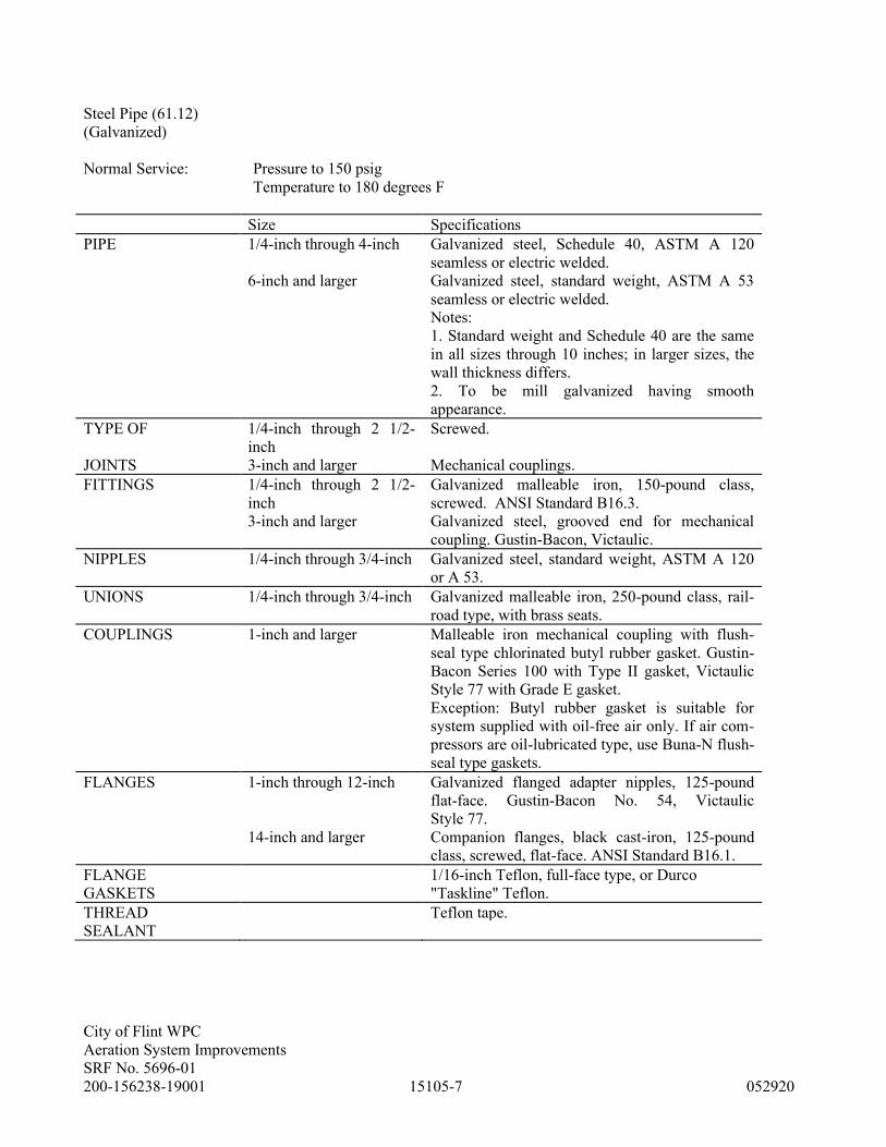
City of Flint WPC
Aeration System Improvements
SRF No. 5696-01
200-156238-19001 15105-7 052920
Steel Pipe (61.12)
(Galvanized)
Normal Service: Pressure to 150 psig
Temperature to 180 degrees F
Size Specifications
PIPE 1/4-inch through 4-inch Galvanized steel, Schedule 40, ASTM A 120
seamless or electric welded.
6-inch and larger Galvanized steel, standard weight, ASTM A 53
seamless or electric welded.
Notes:
1. Standard weight and Schedule 40 are the same
in all sizes through 10 inches; in larger sizes, the
wall thickness differs.
2. To be mill galvanized having smooth
appearance.
TYPE OF 1/4-inch through 2 1/2-
inch
Screwed.
JOINTS 3-inch and larger Mechanical couplings.
FITTINGS 1/4-inch through 2 1/2-
inch
Galvanized malleable iron, 150-pound class,
screwed. ANSI Standard B16.3.
3-inch and larger Galvanized steel, grooved end for mechanical
coupling. Gustin-Bacon, Victaulic.
NIPPLES 1/4-inch through 3/4-inch Galvanized steel, standard weight, ASTM A 120
or A 53.
UNIONS 1/4-inch through 3/4-inch Galvanized malleable iron, 250-pound class, rail-
road type, with brass seats.
COUPLINGS 1-inch and larger Malleable iron mechanical coupling with flush-
seal type chlorinated butyl rubber gasket. Gustin-
Bacon Series 100 with Type II gasket, Victaulic
Style 77 with Grade E gasket.
Exception: Butyl rubber gasket is suitable for
system supplied with oil-free air only. If air com-
pressors are oil-lubricated type, use Buna-N flush-
seal type gaskets.
FLANGES 1-inch through 12-inch Galvanized flanged adapter nipples, 125-pound
flat-face. Gustin-Bacon No. 54, Victaulic
Style 77.
14-inch and larger Companion flanges, black cast-iron, 125-pound
class, screwed, flat-face. ANSI Standard B16.1.
FLANGE 1/16-inch Teflon, full-face type, or Durco
GASKETS "Taskline" Teflon.
THREAD Teflon tape.
SEALANT

City of Flint WPC
Aeration System Improvements
SRF No. 5696-01
200-156238-19001 15105-8 052920
Ductile Iron Pipe (62.5)
Normal Service: Pressure to approx. 250 psig
Temperature to 180 degrees F
Size Specifications
PIPE 3-inch and larger Ductile Iron, ASTM 21.51 (AWWA C151) and
ASTM A 536, Grade 60-45-10 Class 54 cement-
lined interior, coal tar varnish coating - ground-
buried universal rust-inhibitive primer exposed.
TYPE OF 3-inch and larger Push-on joint, compression with restrained
JOINTS mechanical joint fittings - ground-buried, flanged
or grooved coupling - exposed.
FITTINGS 3-inch and larger Ductile Iron, ASA 21.10, 250 psi rating.
GASKETS 3-inch and larger 1/16-inch rubber.
FLANGES 3-inch and larger Ductile iron, ANSI 21.15 (AWWA C115)
(when required) dimensions ANSI B16.1; threads ANSI B 2-1,
bolts ASTM A 307, Grade B. All nuts and bolts to
be cadmium-plated.
NOTE: Ground-buried pipe to be restrained for pressures up to 180 psi as noted in the pipe restraint schedule.
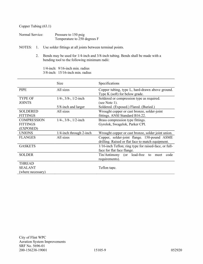
City of Flint WPC
Aeration System Improvements
SRF No. 5696-01
200-156238-19001 15105-9 052920
Copper Tubing (63.1)
Normal Service: Pressure to 150 psig
Temperature to 250 degrees F
NOTES: 1. Use solder fittings at all joints between terminal points.
2. Bends may be used for 1/4-inch and 3/8-inch tubing. Bends shall be made with a
bending tool to the following minimum radii:
1/4-inch: 9/16-inch min. radius
3/8-inch: 15/16-inch min. radius
Size Specifications
PIPE All sizes Copper tubing, type L, hard-drawn above ground.
Type K (soft) for below grade.
TYPE OF 1/4-, 3/8-, 1/2-inch Soldered or compression type as required.
JOINTS (see Note 1).
5/8-inch and larger Soldered. (Exposed.) Flared. (Buried.)
SOLDERED All sizes Wrought copper or cast bronze, solder-joint
FITTINGS fittings. ANSI Standard B16.22.
COMPRESSION 1/4-, 3/8-, 1/2-inch Brass compression type fittings.
FITTINGS Gyrolok, Swagelok, Parker CPI.
(EXPOSED)
UNIONS 1/4-inch through 2-inch Wrought copper or cast bronze, solder joint union.
FLANGES All sizes Copper, solder-joint flange. 150-pound ASME
drilling. Raised or flat face to match equipment.
GASKETS 1/16-inch Teflon; ring type for raised-face, or full-
face for flat face flange.
SOLDER Tin/Antimony (or lead-free to meet code
requirements).
THREAD
SEALANT Teflon tape.
(where necessary)

City of Flint WPC
Aeration System Improvements
SRF No. 5696-01
200-156238-19001 15105-10 052920
PVC Pipe (64.1)
Normal Service: Maximum Pressure: 150 psig
Maximum Temperature: 150 degrees F
Size Specifications
PIPE 1/2-inch through 6-inch PVC Type I, Schedule 80, ASTM D 1785.
TYPE OF 1/2-inch through 6-inch Solvent welded.
JOINTS
FITTINGS 1/2-inch through 6-inch PVC, Schedule 80, socket type, ASTM D 2467.
FLANGES 1/2-inch through 6-inch PVC, 150-pound, flat-face, Schedule 80,
(where necessary) socket type.
GASKETS 1/2-inch through 6-inch 1/16-inch solid neoprene, full-face type.
NOTE: Provide 20-gauge (0.032-inch) aluminum jacket on all piping in return air plenums.
Sodium hypochlorite and sodium hydroxide piping joints shall be made with Oatey, Lo-Voc heavy-duty
gray, Industrial Grade PVC cement. PVC cement shall be NSF listed and meet ASTM D 2564 and D
1412. Cement shall be resistant to caustics and hypochlorites up to 15 percent solution.

City of Flint WPC
Aeration System Improvements
SRF No. 5696-01
200-156238-19001 15105-11 052920
CPVC Pipe (64.8)
Normal Service: Maximum Pressure: 100 psig
Maximum Temperature: 180 degrees F
Size Specifications
PIPE 1/2-inch through 2-inch rigid chlorinated polyvinyl chloride (CPVC)
compound, Type IV Grade I,
with a Cell Classification of 23447 as defined in
ASTM D1784
TYPE OF 1/2-inch through 2-inch Solvent welded.
JOINTS
FITTINGS 1/2-inch through 2-inch CPVC, Schedule 80, socket type, ASTM F 439.
FITTINGS -
THREADED
1/2-inch through 2-inch CPVC, , Schedule 80 ,THREADED, ASTM F 437
(where necessary) Only for transition to different piping system
LISTING approved by NSF
for use with potable water

City of Flint WPC
Aeration System Improvements
SRF No. 5696-01
200-156238-19001 15105-12 052920
Stainless Steel Pipe (66.1)
Normal Service: Pressure to approx. 150 psig
Temperature to 300 degrees F
Size Specifications
PIPE 1/2-inch through 6-inch Types 304, 304L, 316 or 316L stainless steel pipe,
Schedule 5S. ASTM A 312 seamless or electric
welded.
TYPE OF 1/2-inch through 6-inch Butt-welded, Press Fittings or threaded as
required.
JOINTS
FITTINGS 1/2-inch through 6-inch Press Fittings by Viega or approved equal per
ASME A312 or ASTM A554.
Types 304, 304L, 316 or 316L stainless steel,
schedule 5S, butt-welding. ASTM Standard A 403
and ANSI Standard B16.9, or tangential fittings as
manufactured by Horace T. Potts Co. (Speedline)
or by Picor, Inc.
FLANGED 1/2-inch through 6-inch Types 304, 304L, 316 or 316L stub ends, schedule
CONNECTIONS 5S, butt-welding. Type A or B as covered by MSS
or ANSI. All stub ends must be true schedule 5 --
not taper-bored.
Speedline or Camco 150-pound. C.S. lightweight
backup flanges are permitted for stub ends.
GASKETS 1/2-inch through 6-inch Press Fitting O-rings shall be EDPM or FKM
depening on application
1/16-inch solid Teflon, ring type. (Gylon is an
acceptable alternate where cold flow of Teflon
could be a problem.)
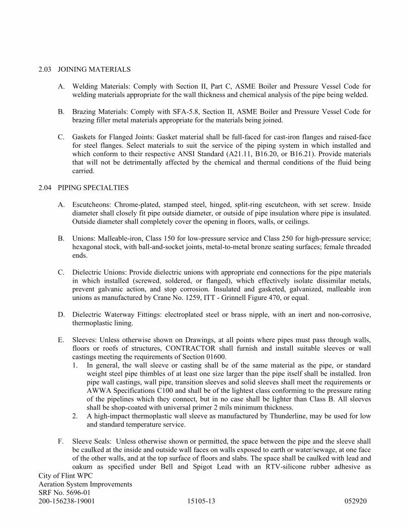
City of Flint WPC
Aeration System Improvements
SRF No. 5696-01
200-156238-19001 15105-13 052920
2.03 JOINING MATERIALS
A. Welding Materials: Comply with Section II, Part C, ASME Boiler and Pressure Vessel Code for
welding materials appropriate for the wall thickness and chemical analysis of the pipe being welded.
B. Brazing Materials: Comply with SFA-5.8, Section II, ASME Boiler and Pressure Vessel Code for
brazing filler metal materials appropriate for the materials being joined.
C. Gaskets for Flanged Joints: Gasket material shall be full-faced for cast-iron flanges and raised-face
for steel flanges. Select materials to suit the service of the piping system in which installed and
which conform to their respective ANSI Standard (A21.11, B16.20, or B16.21). Provide materials
that will not be detrimentally affected by the chemical and thermal conditions of the fluid being
carried.
2.04 PIPING SPECIALTIES
A. Escutcheons: Chrome-plated, stamped steel, hinged, split-ring escutcheon, with set screw. Inside
diameter shall closely fit pipe outside diameter, or outside of pipe insulation where pipe is insulated.
Outside diameter shall completely cover the opening in floors, walls, or ceilings.
B. Unions: Malleable-iron, Class 150 for low-pressure service and Class 250 for high-pressure service;
hexagonal stock, with ball-and-socket joints, metal-to-metal bronze seating surfaces; female threaded
ends.
C. Dielectric Unions: Provide dielectric unions with appropriate end connections for the pipe materials
in which installed (screwed, soldered, or flanged), which effectively isolate dissimilar metals,
prevent galvanic action, and stop corrosion. Insulated and gasketed, galvanized, malleable iron
unions as manufactured by Crane No. 1259, ITT - Grinnell Figure 470, or equal.
D. Dielectric Waterway Fittings: electroplated steel or brass nipple, with an inert and non-corrosive,
thermoplastic lining.
E. Sleeves: Unless otherwise shown on Drawings, at all points where pipes must pass through walls,
floors or roofs of structures, CONTRACTOR shall furnish and install suitable sleeves or wall
castings meeting the requirements of Section 01600.
1. In general, the wall sleeve or casting shall be of the same material as the pipe, or standard
weight steel pipe thimbles of at least one size larger than the pipe itself shall be installed. Iron
pipe wall castings, wall pipe, transition sleeves and solid sleeves shall meet the requirements or
AWWA Specifications C100 and shall be of the lightest class conforming to the pressure rating
of the pipelines which they connect, but in no case shall be lighter than Class B. All sleeves
shall be shop-coated with universal primer 2 mils minimum thickness.
2. A high-impact thermoplastic wall sleeve as manufactured by Thunderline, may be used for low
and standard temperature service.
F. Sleeve Seals: Unless otherwise shown or permitted, the space between the pipe and the sleeve shall
be caulked at the inside and outside wall faces on walls exposed to earth or water/sewage, at one face
of the other walls, and at the top surface of floors and slabs. The space shall be caulked with lead and
oakum as specified under Bell and Spigot Lead with an RTV-silicone rubber adhesive as

City of Flint WPC
Aeration System Improvements
SRF No. 5696-01
200-156238-19001 15105-14 052920
manufactured by General Electric, or sealed with a rubber link seal. Rubber link seal shall be
identical rubber links interconnected with bolts and elongated nuts and washers. The sealing element
shall be made of synthetic rubber material especially compounded to resist aging, ozone, sunlight,
and chemical action. Bolts and metal parts shall be made of galvanized or cadmium-plated steel to
resist corrosion. Rubber link seal joints shall be submitted to ENGINEER for approval.
PART 3 - EXECUTION
3.01 PREPARATION
A. Ream ends of pipes and tubes, and remove burrs. Bevel plain ends of steel pipe.
B. Remove scale, slag, dirt, and debris for both inside and outside of piping and fittings before
assembly.
3.02 INSTALLATION
A. Drawings (plans, schematics, and diagrams) indicate the general location and arrangement of the
piping systems. Location and arrangement of piping layout take into consideration pipe sizing and
friction loss, expansion, pump sizing, and other design considerations. So far as practical, install
piping as indicated. Refer to individual system specifications for requirements for coordination
drawing submittals.
B. Piping shall be exposed, unless indicated otherwise.
C. Install piping free of sags or bends and with ample space between piping to permit proper insulation
applications.
D. Install exposed piping at right angles or parallel to building walls. Diagonal runs are not permitted,
unless expressly indicated on Drawings.
E. Install piping far enough from slabs, beams, joists, columns, walls, and other permanent elements of
the building to permit access for painting. Provide space to permit insulation applications, with
3-inch clearance outside the insulation. Allow sufficient space above removable ceiling panels to
allow for panel removal.
F. Locate groups of pipes parallel to each other, spaced to permit applying full insulation and servicing
of valves.
G. Install drains at low points in mains, risers, and branch lines consisting of a tee fitting, 3/4-inch ball
valve, and short 3/4-inch threaded nipple and cap.
H. Exterior Wall Penetrations: Seal pipe penetrations through exterior walls using sleeves and
mechanical sleeve seals.
I. Fire Barrier Penetrations: Where pipes pass through fire rated walls, partitions, ceilings, or floors, the
fire rated integrity shall be maintained. Refer to Division 7 for special sealers and materials.

City of Flint WPC
Aeration System Improvements
SRF No. 5696-01
200-156238-19001 15105-15 052920
J. Buired Plastic Pipe: Install a yellow insulated copper tracer wire or other approved conductor
adjacent to underground nonmetallic piping. The tracer wire shall terminate above ground at each
end of the nonmetallic piping. The tracer wire size shall not be less than 18 AWG and unsulation
type shall be suitable for direct burial.
3.03 FITTINGS AND SPECIALTIES
A. Use fittings for all changes in direction and all branch connections.
B. Remake leaking joints using new materials.
C. Install strainers on the supply side of each control valve, pressure reducing or regulating valve,
solenoid valve, and elsewhere as indicated.
D. Install unions adjacent to each valve, and at the final connection to each piece of equipment and
plumbing fixture having 2-inch and smaller connections, and elsewhere as indicated.
E. Install flanges in piping 2-1/2-inch and larger, where indicated, adjacent to each valve, and at the
final connection to each piece of equipment.
F. Install dielectric unions to connect piping materials of dissimilar metals in dry piping systems (gas,
compressed air, vacuum).
G. Install dielectric fittings to connect piping materials of dissimilar metals in wet piping systems
(water, steam).
H. HDPE to Metallic
1. Provide an anodeless transition fitting between the underground HDPE gas piping and the
above ground metallic piping.
3.04 JOINTS
A. Steel Pipe Joints:
1. Pipe 2-inch and Smaller: Thread pipe with tapered pipe threads in accordance with ANSI B2.1.
Cut threads full and clean using sharp dies. Ream threaded ends to remove burrs and restore full
inside diameter. Apply pipe joint lubricant or sealant suitable for the service for which the pipe
is intended on the male threads at each joint and tighten joint to leave not more than 3 threads
exposed.
2. Pipe Larger than 2-inch:
a. Weld pipe joints (except for exterior water service pipe) in accordance with ASME Code
for Pressure Piping, B31.
b. Weld pipe joints of exterior water service pipe in accordance with AWWA C206.
c. Install flanges on all valves, apparatus, and equipment. Weld pipe flanges to pipe ends in
accordance with ASME B31.1.0 Code for Pressure Piping. Clean flange faces and install
gaskets. Tighten bolts to torque specified by manufacturer of flange and flange bolts, to
provide uniform compression of gaskets.

City of Flint WPC
Aeration System Improvements
SRF No. 5696-01
200-156238-19001 15105-16 052920
B. Non-ferrous Pipe Joints:
1. Brazed and Soldered Joints: For copper tube and fitting joints, braze joints in accordance with
ANSI B31.1.0 - Standard Code for Pressure Piping, Power Piping, and ANSI B9.1 - Standard
Safety Code for Mechanical Refrigeration.
2. Mechanical Joints: Flared compression fittings may be used for refrigerant lines 3/4-inch and
smaller.
C. Joints for other piping materials are specified within the respective piping system sections.
3.05 FIELD QUALITY CONTROL
A. Testing: Refer to individual piping system Specification Sections.
END OF SECTION

City of Flint WPC
Aeration System Improvements
SRF No. 5696-01
200-156238-19001 15110-1 052920
SECTION 15110 - PROCESS VALVES
PART 1 - GENERAL
1.01 SUMMARY
A. Section Includes: Labor, materials, and equipment necessary for fabrication, production, installation,
and erection of the items specified in this Section and as shown on Drawings or on Valve Schedule
on Drawings.
B. Items furnished under this Section shall be erected under Division 15. Hanger rods, inserts and
supports, flange bolts, and gaskets for valves shall be furnished and installed under Section 15100.
1.02 REFERENCES
A. ANSI:
1. B16.1 Cast Iron Pipe Flanges and Flanged Fittings, Classes 25, 125, 250, and 800.
2. B16.3, B2.1 Threaded Valve Joint Standards.
3. B16-104 Reinforced Teflon Steel Standard.
B. ANSI/AWWA:
1. C110/A21.10 Ductile Iron and Gray Iron Fittings, 3-inch through 48-inch for Water and
Other Liquids.
2. C111/A21.11 Rubber Gasket Joints for Ductile Iron and Gray Iron Pressure Pipe and Fittings.
3. C500 Metal Seated Gate Valves for Water Supply Service.
4. C507 Ball Valves.
5. C504 Rubber Seated Butterfly Valves, 3-Inch through 72-Inch.
6. C508 Swing-Check Valves for Waterworks Service, 2-Inch Through 24-Inch
7. C509 Resilient Seated Gate Valves for Water Supply Service.
8. C512 Air-Release, Air/Vacuum, and Combination Air Valves for Waterworks
Service.
9. C515 Reduced-Wall, Resilient-Seated Gate Valves for Water Supply Service
10. C517 Resilient-Seated Cast-Iron Eccentric Plug Valves
11. C530 Pilot Operated Control Valves
12. C541 Hydraulic and Pneumatic Cylinder and Vane-Type Actuators for Valves and
Slide Gates
13. C542 Electric Motor Actuators for Valves and Slide Gates
14. C550 Protective Interior Coating for Valves and Hydrants
C. ASTM:
1. A 48 Specification for Gray Iron Castings.
2. A 126 Specification for Gray Iron Castings for Valves, Flanges and Pipe Fittings.
3. A 182/A 183M Specification for Forged or Rolled Alloy Steel Pipe Flanges, Forged Fittings
and Valves and Parts for High Temperature Service.
4. A 183 Specification for Carbon Steel Track Bolts and Nuts.
5. A 194/194M Specification for Carbon and Alloy Steel Nuts for Bolts for High Pressure and
High Temperature Service.
6. A 276 Specification for Stainless and Heat Resisting Steel Bars and Shapes.
7. A 436 Specification for Austenitic Gray Iron Castings.

City of Flint WPC
Aeration System Improvements
SRF No. 5696-01
200-156238-19001 15110-2 052920
8. A 536 Specification for Ductile Iron Castings.
9. B 148 Specification for Aluminum Bronze Castings.
10. B 584 Specification for Copper Alloy Sand Castings for General Applications.
11. B 61 Specification for Steam of Bronze Castings.
1.03 SUBMITTALS
A. Shop Drawings: Submit in accordance with Section 01330, Shop Drawings covering the items
included under this Section. Shop Drawing submittals shall include:
1. Each valve, including accessories, shall be identified on Shop Drawings by its respective mark
as noted on Valve Schedule.
B. Operation and Maintenance Manuals: Submit in accordance with requirements of Section 01600,
operation and maintenance manuals for items included under this Section.
C. Warranty: Submit in accordance with requirements of Section 01770, warranties covering the items
included under this Section.
1.04 QUALITY ASSURANCE
A. All Work under this Section shall be performed in accordance with standard practices as
recommended by manufacturer and AWWA.
PART 2 - PRODUCTS
2.01 MANUFACTURERS
A. Subject to compliance with specified requirements, manufacturers offering products which may be
incorporated in Work include:
1. Butterfly Valves (B):
a. DeZurik.
b. Henry Pratt Co.
c. M&H Valve Co.
d. Rodney Hunt Co.
e. Val-matic Valve and Manufacturing Corp.
2. Industrial Butterfly Valves (IB):
a. Cooper Cameron Corp. (Demco Valve).
b. DeZurik SPX.
c. Henry Pratt Co.
d. Hilliburton Co. (Dresser Valve Div.).
e. Kennedy Valve.
f. Keystone Valve.
g. Mark Controls Corp. (Center Line Valve).
3. Resilient Seated Gate Valves (RA):
a. American Flow Control Valves.
b. Clow Valve Co.
c. M&H Valve Co.
d. Mueller Co. (A-2360 Resilient Wedge).
e. U.S. Pipe (Metroseal 250).

City of Flint WPC
Aeration System Improvements
SRF No. 5696-01
200-156238-19001 15110-3 052920
4. Standard Swing Check Valves (C):
a. Clow Valve Co.
b. G.A. Valves (Golden Anderson).
c. Kennedy Valve.
d. M&H Valve Co.
e. Rensselaer Valve Mfg. Co.
5. Double Vane Check Valves (DC):
a. Mission Manufacturing Co. - Duo-Chek.
b. Techno Corporation - Technocheck.
6. Plug Valves (P):
a. Clow Valve Co.
b. DeZurik.
c. Homestead Valve (Div. of Olson Technologies, Inc.).
d. Milliken Valve Co.
e. Henry Pratt Co.
f. Val-Matic Valve and Manufacturing Co.
g. Victaulic Co.
7. Tapping Sleeves and Valves (TPSV):
a. A.P. Smith Co.
b. Clow Valve Co.
c. Kennedy Valve Co.
d. M&H Valve Co.
8. Electric motor open-shut service operators:
a. Rotork.
9. Electric motor operators for throttling service:
a. Rotork.
10. Floor Box:
a. Clow Valve Co.
b. Ludlow.
11. Limit Switches, spring-centered:
a. Allen-Bradley.
b. Square D Co.
12. T-handle Wrench:
a. Clow Valve Co.
2.02 VALVE AND GATE IDENTIFICATION
A. Each valve and gate shall be tagged with its distinguishing mark letter and number. Mark letter and
number will be as listed on Valve Schedule. Identification tag shall be 1-1/2-inch in diameter,
18-gauge polished brass or aluminum with 1/2-inch-high, embossed, black-filled mark letter and
number placed thereon. Tags shall be securely fastened to the valve or gate operator with No. 16
brass jack chain or plastic seals.
2.03 COMPONENTS
A. Industrial Butterfly Valves (IB):
1. Shall be suitable for installation between ANSI B16.1, Class 125 flanges, and shall be designed
for 150 psi working pressure or as herein specified or noted on Valve Schedule. Valves shall
meet or exceed the design strength, testing and performance requirements of AWWA
Standard C504.
City of Flint WPC
Aeration System Improvements
SRF No. 5696-01
200-156238-19001 15110-4 052920
2. Valve bodies shall be cast iron ASTM A 126, Class B, gray iron ASTM A 48, Class 20 or
ductile iron ASTM A 536, Class 65-45-12 or 65-45-15. Valve bodies on exterior valves shall
have exposed surfaces protected with a weather-resistant thermosetting multipolymer resin
coating.
3. Valve discs shall be ductile iron and, where noted on Valve Schedule, coated with EPDM/EPT.
Discs shall be one-piece cast design with no external ribs transverse to the flow. Disc hub and
edge shall be ground and polished to a rounded contour to give full concentric seating.
4. Valve seats shall totally encapsulate the inside surfaces of the valve body and shall also serve as
the flange gaskets. The resilient elastomer valve seat shall be bonded to metallic or plastic
backup ring. Valve seats shall be designed with integral seals at the disc shaft hub areas to
completely isolate the stem, stem bearings and body area from the flowing media. Valve seats
shall be completely field replaceable at the Site without the use of special tools. Seats shall be
Buna N or EPDM/EPT for air.
5. Shafts shall be 316 or 416 stainless steel construction. Valve shafts shall be securely fastened to
the valve disc by 316 stainless steel taper pins, or by a broached connection. Shafts shall be
provided with both a primary and secondary shaft sealing device at each end of the shaft where
the shaft enters the valve body. Upper shaft bearing surfaces shall be adequately designed to
absorb the loads imposed by the service conditions and any side thrusts developed by the
operator and shall be of the permanently lubricated type for valves 12-inch and smaller and self-
lubricating bushing type on valves larger than 12 inches. On valves 30 inches and larger, shaft
seals shall be of the double-chevron bi-directional type suitable for both pressure and vacuum.
Seals may be pre-loaded by a packing gland mechanism. The packing gland, studs, and nut shall
be constructed of corrosion-resistant materials.
B. Resilient Seated Gate Valves (RA):
1. Resilient seated gate valves shall be designed for 150 psi working pressure and shall meet the
requirements of AWWA Specification C509 or C515 except as otherwise specified herein.
Valves shall be cast or ductile iron body, bronze stem, O-ring stem seal, and non-rising stem.
The interior and exterior surfaces of the valve body shall be coated with an epoxy coating
meeting the requirements of AWWA C550. The bronze or iron or ductile iron wedge shall be
fully encapsulated with molded rubber. No bare metal shall be left exposed. The valve shall seal
on both sides of the wedge. Gate valves shall have a clear waterway equivalent in area, when
fully open, to that of the connecting pipe. Valves shall be made to open when turned to the left,
or counterclockwise. The gate valves shall have square wrench nuts mounted on non-rising
stems. All fasteners shall be stainless steel. Ground-buried gate valves shall be furnished with
valve boxes. Flanges shall meet the requirements of AWWA C115 (ANSI 21.15). Two
complete sets of joint accessories shall be furnished with each valve.
2. The force mains will be laid with a minimum 5 feet of cover or as noted on Drawings. One
operating wrench of suitable length shall be provided under this Section.
C. Standard Swing Check Valves (C):
1. Standard swing check valves shall meet the requirements of ANSI/AWWA C508.. Check
valves shall be cast or ductile iron body with end flanges conforming to ASME B16.1 Class
125. Reslient to metal type seat shall be provided with stainless steel seating surface
mechanically attached to machined body area with the buna-N seat material integral with or
mechanically attached to the disc. Check valves shall be of the balanced single disc type with
the disc hinged at the top, with outside lever and adjustable weight or spring. A clear waterway
opening equal to the full area of the connecting pipe shall be provided when the valve is open.

City of Flint WPC
Aeration System Improvements
SRF No. 5696-01
200-156238-19001 15110-5 052920
2. Disc shall be shall be cast or ductile iron.. Hinge pins shall be one piece stainless steel and
protrude through both sides of the body. Bronze or stainless steel bushings with adjustable
packing or O-ring seal shall be provided where pins pass through the valve body.
3. Valves shall be interior coated with epoxy meeting requirements NSF/ANSI 61 approved epoxy
in accordance with AWWA C550 and, as minimum, be painted with primer on the exterior.
D. Double Vane Check Valves (DC):
1. Valves shall be of the spring-loaded, double-vane type with flanged ends or suitable for
mounting between two flanges. Valves shall be designed for 150 psi working pressure except as
herein specified or shown on Valve Schedule. Torsion springs shall be of a heat-resistant
material.
2. Valves shall be furnished with cast iron bodies, bronze mounted, Buna-N seal, nickel-plated
steel stops, 316 stainless steel pin and spring and cast iron pin retainer.
E. Plug Valves (P):
1. Plug valves shall meet the requirements of AWWA C517, be nonlubricated, eccentric type with
nitrile butadiene (hycar) or Buna-N resilient faced plugs. End connections shall generally be
flanged or grooved for inside valves and mechanical joint for exterior ground-buried valves.
Port areas shall be equal to at least 80 percent of the nominal size pipe area. Valve shall be
suitably marked to indicate whether it is open or closed.
2. The seating surface of the valve body shall be welded in stainless steel or nickel. Bearings at the
top and bottom supporting the rotating element shall be self-lubricating, corrosion-resistant
type, suitable for sewage plant service. The valve shall be of the bolted bonnet design. Packing
shall be visible for inspection without dismantling valve or removing operator. The packing
shall be adjustable and replaceable without disassembling of the valve and actuator. The valve
body shall be cast or ductile iron marked to show seat side of valve.
3. Plug valves shall be of adequate design to operate with a pressure of 50 psi on both sides or on
either side of the valve without leakage.
2.04 VALVE JOINTS
A. Bell and Spigot Lead: Bell lead joints shall meet the requirements of ANSI/AWWA C110/A21.10.
B. Flange Joint: Flanges shall meet the requirements of ANSI-B16.1 Standard Class 125, except that
bolt holes at shaft hubs may be drilled and tapped on the flanges. Flange faces shall be coated with a
rust inhibitor immediately after drilling.
C. Grooved Coupling: Grooved coupling joints shall be the rigid type and shall have housing fabricated
in 2 or more parts of malleable iron in accordance with ASTM Specification A 47, Grade C32510.
Ends shall be factory grooved in accordance with the coupling manufacturer's standard groove
dimension. Bolts shall be oval neck track head type with hexagonal heavy nuts, per ASTM A 183
and A 194/A 194M. Gasket material shall be Grade H, E chlorinated butyl, or E.P.D.M. for water
service and Grade T Buna-N for sewage.
D. Mechanical joints shall conform to ANSI/AWWA C110/A 21.10 and ANSI/AWWA C111/A 21.11.
E. Push-on joints shall conform to ANSI A21.11 and AWWA C111.
F. Screwed joints shall conform to American Standard dimensions ANSI B16.3 and threads
ANSI B2.1.

City of Flint WPC
Aeration System Improvements
SRF No. 5696-01
200-156238-19001 15110-6 052920
G. Wafer joints shall be flat face or raised face for use between standard flanges.
2.05 ACCESSORIES
A. Manual Operators: Operators shall be designed with a safety factor of 5 for torsional and shear
stresses. The operating mechanism shall be so located and so designed that parts subject to the
maintenance shall be easily accessible.
1. Manual operators shall be so sized that a maximum of 80 pounds of rim force/pull is required
for operation.
2. Positions of operators shall be approved by ENGINEER.
3. Valve shall be made to open when turned to the left or counterclockwise.
4. The direction of the operator to open position shall be indicated on the operator.
5. Bevel gear activators shall provide vertical mounting of the handwheel. Handwheels shall be
included.
6. Crank/Handle: Cranks shall be cast iron with a rotating brass grip. They shall be a maximum of
15 inches in length and keyed to the operator nut.
7. Chainwheels shall be cast iron and furnished complete with chain and guides. Chain shall be
galvanized and shall be looped to extend to within 4 feet of the floor below the valve.
8. Handwheels shall be fabricated steel. They shall be a maximum of 30 inches in diameter and
keyed to the operating nut.
9. Lever shall be fabricated steel, shall include a setscrew and be grease lubricated.
10. Chain lever shall indicate chain and lever. Materials shall be galvanized.
11. Infinite lever shall be of extra heavy steel and capable to be moved to any position and locked in
place by a simple wing nut.
12. Position lever shall be of extra heavy steel with a multiple position throttling plate.
13. Wrench heads shall be cast iron with setscrew. They shall be furnished for wrench nuts except
where extension stems or T-handle wrenches are required.
14. Wrench nuts shall be provided with a 2-inch operating nut when a T-handle wrench or
extension stem is required. Other wrench nuts shall be furnished with a wrench head.
B. Motor:
1. Electric Motor Open-Close Service: Electric motor actuators for open-shut service shall meet
the requirements of ANSI/AWWA C542, except as herein specified.
a. Controls shall be "integrally mounted" as part of the actuator body. If designated on
Valve Schedule a "wall-mounted enclosure" or “remote control station” shall be provided
for mounting important actuator controls separate from the actuator body in an easily
accessable location. Deviations from the Valve Schedule will not be accepted.
b. The valve manufacturer shall provide the required seating, unseating dynamic torque
requirements and any other trust or static loading information necessary to properly size
the electric motor actuator.
c. Electrical equipment shall be mounted in a NEMA 4 or 7 enclosure whether on the valve
body or in the wall-mounted enclosure. The enclosure shall be NEMA 4 unless shown
otherwise on Valve Schedule.
d. Actuator materials of construction shall be selected by the manufacturer to be compatable
with the environmental conditions that will be present at the valves installed location.
Actuators installed in water treatment plants or other potable water applications shall have
materials that comply with the Safe Water Drinking Act requirements including food grade
lubricants.

City of Flint WPC
Aeration System Improvements
SRF No. 5696-01
200-156238-19001 15110-7 052920
e. Motorized valve actuators shall include the motor, reversing starter with remote-off-local
switch, associated gearing, limit switches, torque switches, auxiliary handwheel for manual
operation, a valve mounted mechanical dial valve position indicator, Open-Close-Stop
position switch or push-buttons, and accessories as listed on Valve Schedule.
f. The remote control station shall be provided by the actuator manufacturer, have a NEMA 4
rated enclosure unless noted otherwise on Schedule and be powered by the actuator.
Signal and power wires shall be integrally linked to the actuator with wires landed on
appropriately marked termainal stips in the actuator. Unit shall be capable of being
mounted 300 feet away from the actuator and with enclosure suitable for wall, rack or pole
mounting. Locable Local-Off-Remote selector and Open-Close valve postion switches,
push buttons, and open-closed indicator lights or valve position indication shall be
provided.
g. Wires shall be tagged at each end of the wire with individual wire markers. Each terminal
of the terminal strips shall be numbered and identified with a marker. Schematics shall be
provided with Shop Drawings showing wire numbers, terminals, field wiring, etc.
Connections for remote equipment shall be wired to terminal blocks. Equipment shall be
factory wired and tested before shipment.
h. The motor starters shall be the solid state reversing contactor type complete with gang-
operated switch, 2 solid state reversing contactors, 120 volt control power transformer
when motor voltage is other than 120 volt, thermal overload protection for each phase, and
associated wiring. Operating voltage shall be 460 Volts unless indicated otherwise on
Valve Schedule.
i. Limit switches shall be provided at the extreme open and close position of the operator
travel. At least 2 independent switches at each end of motor travel shall be provided as
standard for the local indicator lights and interlocking. An additional 4 switches shall be
provided for remote use.
j. Torque switches shall be provided in both the open and closed circuits of the operators.
The torque switches shall be field adjustable and designed to stop the operator motor when
the torque exceeds safe limits for either the operator or the valve. An electrical or
mechanical interlock shall be provided to prevent the open torque switch from tripping
when unseating a torque seated valve.
k. A local mechanical dial position indicator shall be provided on the valve operator to
indicate the position of the valve.
l. Motors shall be standard-duty rated, totally enclosed nonventilated, Class B insulated,
60 hertz and specially designed for valve service. If voltage and phase are not noted on
Valve Schedule configure motors for 460 Volt three phase service. The design shall
combine low inertia with a high starting and stalling torque.
m. Lost motion drive for increased unseating torque shall be provided.
n. Unless indicated otherwise on Valve Schedule the actuator shall be sized to stroke valves
from full open to full closed and vise versa in one to three minutes under the full specified
unbalance operating head stated in the Specifications and at a frequency not to exceed 60
cycles per hour. The motor winding temperature rise shall be NEMA standard for Class B
insulation at the rated service factor load.
o. Gear case shall be cast iron. Pedestals shall be fabricated steel or cast iron. Stem nut shall
be high-tensile bronze.
p. A heater shall be provided if indicated in the Schedule to prevent condensation in the
controls cavity and terminal chamber of the actuator body. Heaters shall be 120 V
powered. Multiple heaters shall be provided if necessary depending on the actuator body
configuration.

City of Flint WPC
Aeration System Improvements
SRF No. 5696-01
200-156238-19001 15110-8 052920
q. Mechanical manual operation shall be provided by a clutchable handwheel drive
mechanism completely independent from the motor gearing. Hand operation shall be direct
drive permitting fast manual valve operation. Failure of motor gearing due to power failure
or gearing problem shall not prevent handwheel operation. Manual operation shall prevent
(disconnect) electrical operation. Gear reducers shall be provided for manual handwheel if
required. Maximum rim force required for handwheel operation shall not exceed 40
pounds for dynamic loads. Manual operator shall engage the actuators lost motion device.
2. Electric Motor Throttling Service:
a. Electric motor actuator for throttling service on the valves shall meet the requirements of
ANSI/AWWA C542 except as herein specified. Enclosures shall be NEMA 4 unless
shown otherwise on Valve Schedule.
b. The valve operator torque shall be as required for a 150 psi pressure drop across the valve,
minimum, except those for low pressure air service. The valve operator torque for low
pressure air service valves shall be as required for a 25 psi pressure drop across the valve,
minimum.
c. The valve manufacturer shall provide the operating seating, unseating and dynamic torque
requirements along with any other thrust or static loading information necessary to
properly size the electric motor actuator.
d. Actuator materials of construction shall be selected by the manufacturer to be compatable
with the environmental conditions that will be present at the valves installed location.
Actuators installed in water treatment plants or other potable water applications shall have
materials that comply with the Safe Water Drinking Act requirements including food grade
lubricants.
e. Mechanical parts shall be designed for safety factor of at least 2. Construction of the
operator shall be such that it may be mounted in any position required to facilitate manual
operation. Manual operation of the valves shall be possible by a handwheel attached to the
mechanism. Power to motor circuit shall be automatically disconnected to prevent
accidental electric operation during manual operation. A mechanical dial position indicator
shall be provided to continuously indicate valve position. Operator bearings shall be self-
lubricating type or lubricated for life before operator is sealed at the factory.
f. The operator motor shall be heavy-duty with continuous duty rating and totally enclosed
and nonventilated. The motor shall be equipped with thermal overload protection.
Operating voltage shall be as listed on Valve Schedule.
g. The winding temperature rise shall meet NEMA standard for the class of insulation used at
the rated service factor load. The motor shall be for high torque variable speed duty. The
motor shall be reversible. A 4-20 mA throttling signal shall be provided by others. Control
interface electronics, motor controller, and appurtenances to accept this signal and position
the valve between 0 and 90 degrees based on the value of the throttling signal shall be
provided with the valve operator. The controller shall be provided complete with NEMA 4
enclosure, Auto-Manual selector switch and Open, Close push-buttons. Controller shall be
completely solid state; contactors are not acceptable. Motor and controller shall be suitable
for 600 starts per hour. Controllers shall accept an isolated 4-20 mA signal for valve
positioning from a remote source. Valve operators shall be equipped to be field adjustable
to fail open, fail closed, or fail in place upon loss of control signal (4-20 mA). Actuators
shall be set up to fail in place unless otherwise noted on Valve Schedule.
h. The actuator motor gear train in conjunction with any gearing provided as part of the valve
shall be pre-selected to have a stroking time from opento close or vise versa between 1 and
3 minutes or as shown on Valve Schedule.
i. Limit switches shall be provided at the extreme open and close position of the operator
travel. At least 2 independent switches at each end of motor travel shall be provided as

City of Flint WPC
Aeration System Improvements
SRF No. 5696-01
200-156238-19001 15110-9 052920
standard for a local indicator and interlocking. An additional switch shall be provided at
each end for remote use.
j. Motor circuit limit switches shall be of the direct break type. Limit switches shall be
adjustable. Limit switch contacts shall be isolated. Auxiliary switches for secondary
functions shall be of the cam-operated, spring leaf type. The operator shall be equipped
with a torque switch for protection in the closing direction. An electrical or mechanical
interlock shall be provided to prevent the open torque switch from tripping when unseating
a torque-seated valve. In the event of power failure, the operator shall lock in the last
control position until power is restored or switched over to standby power or the manual
operating handwheel is engaged.
k. Torque switches, limit switches, and motor thermal switches are to be mounted as required
inside the housing and connected to the master terminal strip. Provisions shall be made for
2 internal potentiometers for feedback control operations and for remote valve position
indicator. Wiring within operator shall be incorporated in a standard laced wiring harness
using compression connectors and terminal strips. Internal wiring shall be UL approved for
105 degrees C operation. Insulation shall be suitable for 600 volts.
l. Wires shall be tagged at each end of the wire with individual wire markers. Each terminal
of the terminal strips shall be numbered and identified with a marker. Schematics shall be
provided with Shop Drawings showing wire numbers, terminals, field wiring, etc.
Connections for remote equipment shall be wired to terminal blocks. Equipment shall be
factory wired and tested before shipment.
3. Electric Motor Actuator Retrofit.
a. Existing valves shall be retrofitted with new motor actuators when shown on the Valve
Schedule.
b. Prior to submitting shop drawings the actuator manufactures representative shall perform a
field inspection to verify mounting requirements and existing configurations that may
effect valve mounting.
c. If the existing valve and operator need to be partially disassembled or operated through
open-close cycles to acquire the necessary information for installation of new actuators the
Engineer and Owner shall be notified in advance to allow time for scheduling.
d. Actuator representative is responsible to either contact the existing valve manufacturer to
obtain torque requirements. If this information is not available loadings shall be as
determined by the actuator manufacturer based on field observation and measurements of
existing actuator and anciallary support utilities, historical data of similar valves or other
means. Actuator manufacturer shall assume increased torque will be required for old
valves and make allowances when sizing new actuators.
e. Adapter plates, bushings, couplings, mounting brackets, secondary gear assemblies and
any other items necessary for proper actuator mounting shall be provided. If not indicated
otherwise materials shall be compatible with the environment at the mounting location.
f. Actuator representative shall perform installation and start-up site visits to ensure the
actuators are functioning properly and communicating with the control system.
1) Actuator representative shall configure the valve including setting the open/close
limits and seating/unseating torque settings. All settings shall be carefully adjusted to
avoid overloading existing valve components.
2) Installation Check: The manufacturer shall provide the services of a factory-trained
representative to check the installation of all equipment installed in this Section. The
services shall be as noted in Section 01600.
C. Bench Stand: Bench stands shall meet the requirements of floor stands as specified in this Section,
except that baseplates shall replace pedestals.

City of Flint WPC
Aeration System Improvements
SRF No. 5696-01
200-156238-19001 15110-10 052920
D. Remote Control Station: The control package shall consist of indicating lights, Open-Close-Stop
push-button stations, Local-Remote control selector, strip headers, and wiring factory assembled,
mounted in a NEMA 4 enclosure unless otherwise noted on Valve Schedule.
E. Extension Bonnet (Length): Extension bonnets shall be cast iron and be provided complete with
galvanized assembly bolts.
F. Extension Stem/Shaft (Length): Extension stems shall be 304 or 303 stainless steel with bronze
couplings. Stems of more than one section shall be jointed by bronze couplings threaded and keyed
to the stems. Extension stems shall have a 2-inch wrench nut end connection for T-handle wrench
operation.
1. Extension shafts shall be 304 or 303 stainless steel with universal joint couplings.
G. Floor Box (Length): Where openings through concrete slabs are provided for key operation of valves
and extension stems connected therewith, the operating nut being in or below the slab, such openings
shall be provided with a floor box, complete with cover. Each floor box shall be of the depth
required for installation as shown on Valve Schedule and shall have cast on the cover an appropriate
name designating the service for which the valve is used. In addition, where the operating nut is in
the slab, the floor box shall be bronze bushed; where below, the opening in the bottom of the box
shall be sufficient for passage of the operating key.
1. Each floor box and cover therefor shall be coated by dipping in hot asphaltum varnish.
H. Floor Stand: Floor stands shall meet the requirements of AWWA C501 for Manual Operating
Mechanism except as specified in this Section.
1. Floor stands shall be a high-strength cast iron pedestal type furnished with lubrication fittings
and stainless steel, double-nutted anchor bolts.
2. Geared floor stands shall have weatherproof housings.
3. Floor stands shall be provided with a galvanized steel stem cover and position indicator, and the
direction of rotation to open the valve shall be indicated.
4. The operating stem will be 304 or 303 stainless steel.
5. A sleeve made from standard weight galvanized steel pipe shall be provided for the opening in
the floor beneath each operating stand.
I. Position Indicator: Position indicators shall be of bronze or cast iron construction.
1. Limit Switch. Two limit switches shall be factory-mounted to the valve for indicating full open
and full closed positions.
J. Manual Screw: Manual screw operators shall meet the requirements of AWWA C504 operators.
K. Remote Position Indicator: Remote position indicators shall be the isolated 1,000 ohm potentiometer
design for use with a remote position indicator. Resolution of 1/2 percent shall be required and
potentiometer shall be directly attached to or geared from the valve operating shaft.
L. Stem Cover: Stem covers shall be galvanized steel with position indicators and cap.
M. Stem Guide: Stem guides shall be cast iron ASTM A 126, Class B, construction with bronze
bushings adjustable in two directions and provided with mounting assembly and anchor bolts of
stainless steel. The minimum thickness of any portion shall be 1/2 inch.

City of Flint WPC
Aeration System Improvements
SRF No. 5696-01
200-156238-19001 15110-11 052920
N. Valve Box (Length): Valve boxes shall be either cast iron or ABS plastic. Cast iron lids shall be
provided with valve boxes and shall be marked "WATER" in raised letters.
1. Cast iron boxes shall be of the 3-piece adjustable type. A Number 6 base shall be furnished with
valves 8 inches or less, and a Number 160 base shall be provided for valves over 8 inches.
2. ABS plastic boxes shall be of high-grade ABS polymer, two sections, adjustable to varying,
desired grade levels by means of a friction design (upper section slides inside lower section),
with base to fit various sized valves with arch.
3. Plastic material shall meet requirements of ASTM D 1788.
4. Cast iron material shall meet requirements of ASTM A 126-B or ASTM A 48, Class 30B.
5. Bolt material shall meet requirements of ASTM B 316 and B 253.
6. A magnet shall be permanently molded into both the upper and lower sections for easy locating
with a dip needle or magnetic locator.
O. Wall Bracket: Wall brackets shall be cast iron and provided with stainless steel assembly and anchor
bolts.
PART 3 - EXECUTION
3.01 ERECTION
A. Equipment provided under this Section shall be fabricated, assembled, erected, and placed in proper
operation condition in full conformity with detail drawings, specifications, engineering data,
instructions, and recommendations of the equipment manufacturer approved by ENGINEER.
B. Equipment furnished under this Section shall be installed under Section 15100.
3.02 FIELD QUALITY CONTROL
A. Installation: Special attention shall be given by CONTRACTOR to ensure that items furnished under
this Section are installed in accordance with manufacturer's recommendations.
END OF SECTION

City of Flint WPC
Aeration System Improvements
SRF No. 5696-01
200-156238-19001 15115-1 052920
SECTION 15115 - PLUMBING VALVES
PART 1 - GENERAL
1.01 SUMMARY
A. Section Includes: General duty valves common to most mechanical piping systems.
B. Refer to system specifications for valves to be used for a given service. Then use the following tables
for a complete description of each type of valve.
C. Special purpose valves are specified in individual piping system specifications.
1.02 SUBMITTALS
A. Shop Drawings: Submit in accordance with requirements of Section 01330, Shop Drawings covering
the items included under this Section.
1. Product data, including body material, valve design, pressure and temperature classification,
end connection details, seating materials, trim material and arrangement, dimensions and
required clearances, and installation instructions.
1.03 QUALITY ASSURANCE
A. Regulatory Requirements: Comply with the provisions of the following:
1. ASME B31.9, "Building Services Piping."
2. ASME B31.1, "Power Piping."
B. Manufacturers Standardization Society of the Valve and Fittings Industry (MSS) Compliance:
Comply with the various MSS Standard Practices referenced.
1.04 DELIVERY, STORAGE, AND HANDLING
A. Preparation for Transport: Prepare valves for shipping as follows:
1. Ensure valves are dry and internally protected against rusting and corrosion.
2. Protect valve ends against damage to threads, flange faces, and weld ends preps.
3. Set valves in best position for handling. Set globe and gate valves closed to prevent rattling; set
ball and plug valves open to minimize exposure of functional surfaces; set butterfly valves
closed or slightly open; and block swing check valves in either closed or open position.
B. Storage: Use the following precautions during storage:
1. Do not remove valve end protectors, unless necessary for inspection then reinstall for storage.
2. Protect valves from weather; store valves indoors. Maintain valve temperature higher than the
ambient dewpoint temperature. If outdoor storage is necessary, support valves off the ground or
on pavement in watertight enclosures.
C. Handling: Use a sling to handle valves whose size requires handling by crane or lift. Rig valves to
avoid damage to exposed valve parts. Do not use handwheels and stems as lifting or rigging points.
City of Flint WPC
Aeration System Improvements
SRF No. 5696-01
200-156238-19001 15115-2 052920
PART 2 - PRODUCTS
2.01 MANUFACTURERS
A. Subject to compliance with specified requirements, manufacturers offering products which may be
incorporated in Work are listed in the valve Schedules.
2.02 VALVE FEATURES
A. Valve Design: Rising stem or rising outside screw and yoke stems.
1. Nonrising stem valves may be used where headroom prevents full extension of rising stems.
B. Pressure and Temperature Ratings: As scheduled and required to suit system pressures and
temperatures.
C. Sizes: Same sizes as upstream pipe, unless otherwise indicated.
D. Operators: Provide the following special operator features:
1. Handwheels, fastened to valve stem, for valves other than quarter turn.
2. Lever handles, on quarter-turn valves 6-inch and smaller, except for plug valves. Provide plug
valves with square heads; provide one wrench for every 10 plug valves.
3. Chainwheel operators, for valves 2-1/2-inch and larger, install 72 inches or higher above
finished floor elevation. Extend chains to an elevation of 5'-0" above finished floor elevation.
4. Gear driven operators, on quarter-turn valves 8-inch and larger.
E. Extended Stems: Where insulation is indicated or specified, provide extended stems arranged to
receive insulation.
F. Bypass and Drain Connections: Comply with MSS SP-45 bypass and drain connections.
G. End Connections: As indicated in the valve specifications.
1. Threads: Comply with ANSI B1.20.1.
2. Flanges: Comply with ANSI B16.1 for cast iron, ANSI B16.5 for steel, and ANSI B16.24 for
bronze valves.
3. Solder-Joint: Comply with ANSI B16.18. Where soldered end connections are used, use solder
having a melting point below 840 degrees F for gate, globe, and check valves; below 421
degrees F for ball valves.

City of Flint WPC
Aeration System Improvements
SRF No. 5696-01
200-156238-19001 15115-3 052920
GATE VALVES (101)
Subsection Valve
Number Size Specifications
101.1 1/4" - 2" Bronze, Class 125 (200 WOG, screwed, RS, split
wedge, union bonnet. C-430 UB, J-62U, L-3125,
P- 2700, S-B-106 (Class 125), S-B-121 (Class
150).
2-1/2" - 16" IBBM, Class 125 (200 WOG), flanged, RS, solid
wedge, bolted bonnet. C-465-1/2, J-651-A, L-
1430, P-1793, S-G-623.
101.2 1/4" - 1-1/2" Bronze, 200-pound class, screwed body, RS, solid
wedge, union bonnet. C-424, J-270U, L- 2227, P-
2375-S, S-B-132.
2" - 16" IBBM, Class 125 (200 WOG), flanged, RS, solid
wedge, bolted bonnet. C-465-1/2, J-651-A, L-
1430, P-1793, S-G-623.
101.3 1/4" - 1-1/2" Bronze, 200-pound class, screwed body, RS, solid
wedge, union bonnet. C-424, J-270U, L- 2227, P-
2375-S, S-B-132.
2" - 24" Cast steel, Class 150, RS, solid or flexible wedge,
bolted bonnet. Use weld end body except where
hazardous environment precludes welding or
when replacing Class 125 valve to handle higher
service conditions.
W.E. Valves: C-47-1/2 XU-F for 2" - 16", C-47-
1/2 XU for 18"-24", J-2009-B8F, L-1513, P-
1503-N W.E. for 2"-12", P-1503 W.E. for 14"-
24", S-15-OW- U for 2"-12", S-15-OW-11 for
14"-24"
Flanged Valves: C-47XU-F for 2"-16", C47XU
for 18"-24", J-1009-B8F, L-1502, P-1503-N F.E.
for 2"- 12", P-1503 F.E. for 14"-24", S-15-OF-U
for 2"-12", S-15-OF- 11 for 14"-24".

City of Flint WPC
Aeration System Improvements
SRF No. 5696-01
200-156238-19001 15115-4 052920
BALL VALVES (104)
Subsection Valve
Number Size Specifications
104.8 1/4" - 2" Stainless steel, screwed, blow-out proof stem,
Teflon seats and seals. Consolidated Brass
"Apollo" series 76, Crane 950-TF, Jenkins 1350,
Jamesbury 11-3600MT, Whitey "60" Series.
NOTES: 1. Round or oval handles are available from most manufacturers and should be considered where a
valve may be subject to accidental operation or may cause personnel injury.

City of Flint WPC
Aeration System Improvements
SRF No. 5696-01
200-156238-19001 15115-5 052920
HOSE BIBB/WALL HYDRANT (109)
Subsection Valve
Number Size Specifications
109.3 1-1/2" Flushing hose bibb, 125-pound, bronze gate valve
with fire hose thread and protective cap with
chain.
109.5 3/4" - 2" Corporation cock, 125-pound, solid head, plain
top, flared coupling, per AWWA C800. Ford
Meter Box Company.
CHECK VALVES (110)
Subsection Valve
Number Size Specifications

City of Flint WPC
Aeration System Improvements
SRF No. 5696-01
200-156238-19001 15115-6 052920
CHECK VALVES (110)
Subsection Valve
Number Size Specifications
110.5 1/2" through 6" Stainless steel, Class 150, swing check, Teflon
seat and seals, Flanged ends. Crane 61676-BB
series or approved equal.

City of Flint WPC
Aeration System Improvements
SRF No. 5696-01
200-156238-19001 15115-7 052920
PART 3 - EXECUTION
3.01 EXAMINATION
A. Examine valve interior through the end ports, for cleanliness, freedom from foreign matter and
corrosion.
B. Examine mating flange faces for conditions which might cause leakage. Check gasket material for
proper size, material composition suitable for service, and freedom from defects and damage.
C. Prior to valve installation, examine the piping for cleanliness, freedom from foreign materials, and
proper alignment.
D. Replace defective valves with new valves.
3.02 VALVE ENDS SELECTION
A. Select valves with the following ends or types of pipe/tube connections:
1. Steel Pipes Sizes, 2-Inch and Smaller: threaded or grooved end.
2. Steel Pipe Sizes 2-1/2-Inch and Larger: grooved end or flanged.
3.03 VALVE INSTALLATIONS
A. General Application: Ball valves in sizes 2-inch and smaller, and butterfly valves in sizes 2-1/2-inch
and larger, are to be used unless gate or globe valves are specifically designated on Drawings. Refer
to piping system specification sections for specific valve applications and arrangements.
B. Locate valves for easy access and provide separate support.
C. Install valves and unions for each fixture and item of equipment to allow equipment removal without
system shut down. Unions are not required on flanged devices.
D. Install valves in horizontal piping with stem at or above the center of the pipe.
E. Install valves in a position to allow full stem movement.
3.04 FIELD QUALITY CONTROL
A. After piping systems have been tested and put into service, but before final adjusting and balancing,
inspect each valve for leaks. Adjust or replace packing to stop leaks; replace valves if leak persists.
3.05 ADJUSTING AND CLEANING
A. Clean mill scale, grease, and protective coatings from exterior of valves and prepare valves to
receive finish painting or insulation.
END OF SECTION

City of Flint WPC
Aeration System Improvements
SRF No. 5696-01
200-156238-19001 15125-1 052920
SECTION 15125 - METERS, GAUGES, SWITCHES AND CONTROLS
PART 1 - GENERAL
1.01 SUMMARY
A. Section Includes:
1. Pressure Gauges.
1.02 SUBMITTALS
A. Submit in accordance with requirements of Section 01330, Shop Drawings covering the items
included under this Section.
1. Product data for each type of device: Include scale range, ratings, and calibrated performance
curves, certified where indicated. Submit schedule showing manufacturer's figure number, scale
range, location, and accessories for each meter and gauge.
2. Product certificates signed by manufacturers of meters and gauges certifying accuracies under
specified operating conditions and products' compliance with specified requirements.
B. Operation and Maintenance Manuals: Submit in accordance with requirements of Section 01600,
operating and maintenance manuals for items included under this Section..
1.03 QUALITY ASSURANCE
A. UL Compliance: Comply with applicable UL standards pertaining to meters and gauges.
B. ASME, ANSI, and ISA Compliance: Comply with applicable portions of ASME, ANSI, and
Instrument Society of America (ISA) standards pertaining to construction and installation of meters
and gauges.
PART 2 - PRODUCTS
2.01 MANUFACTURERS
A. Subject to compliance with specified requirements, manufacturers offering products which may be
incorporated in Work include:
1. Pressure Gauge:
a. Ashcroft, Model Type 1279.
b. Trerice, Model No. 450LFB.
c. Weksler “Royal AY14.”
2.02 MATERIALS
A. Pressure Gauge: Pressure gauges shall be liquid filled with a fiberglass-reinforced polypopylene case
and ring, 4-1/2-inch steel dial with white background and black markings, clear glass window,
micro-adjustable aluminum pointer with black finish, brass movement with milled teeth, bourdon
tube of drawn Grade A phosphor bronze with silver brazed joints, and a 1/4-inch NPT brass bottom
outlet with shutoff valve.

City of Flint WPC
Aeration System Improvements
SRF No. 5696-01
200-156238-19001 15125-2 052920
1. Accuracy shall be 1/2 percent of full scale, meeting ASME Grade 2A B40.1.
2. Scale range shall be 0 to 100 psi unless noted on Drawings.
3. Seals shall be provided for all non-clean water applications. Seals and diaphragms shall be
suitable for the service provided.
4. Provide protective siphon when used for steam service.
PART 3 - EXECUTION
3.01 INSTALLATION OF PRESSURE GAUGES
A. Install pressure gauges in piping tee with pressure gauge valve, located on pipe at most readable
position.
B. Install in the following locations, and elsewhere as shown on Drawings:
1. At each pump.
2. At discharge of each pressure-reducing valve.
3. At building water service entrance.
3.02 INSTALLATION OF TEST PLUGS
A. Test Plugs: Install in piping tee where indicated, located on pipe at most readable position. Secure
cap.
3.03 ADJUSTING AND CLEANING
A. Adjust faces of meters and gauges to proper angle for best visibility.
B. Clean windows of meters and gauges and factory-finished surfaces. Replace cracked and broken
windows, and repair scratched and marred surfaces with manufacturer's touch-up paint.
3.04 CONNECTIONS
A. Piping installation requirements are specified in other Sections of Division 15. Drawings indicate the
general arrangement of piping, fittings, and specialties. The following are specific connection
requirements:
1. Install meters and gauges piping adjacent to machine to allow servicing and maintaining of
machine.
END OF SECTION

City of Flint WPC
Aeration System Improvements
SRF No. 5696-01
200-156238-19001 15140-1 052920
SECTION 15140 - WATER DISTRIBUTION PIPING
PART 1 - GENERAL
1.01 SUMMARY
A. Section includes the following:
1. Water Distribution Piping System:
a. Potable cold and hot, water system.
b. Non-Potable cold water system.
2. Service Water Distribution System.
a. Plant effluent water distribution system.
b. Piping, fittings, and specialties.
1.02 DEFINITIONS
A. Water Distribution Piping: A pipe within the building or on the premises which conveys water from
the water service pipe, or meter, to the points of usage. This definition includes all potable, Non-
potable, service, and effluent water piping.
B. Potable Water Piping: The pipe from the water main, or other source of potable water supply, to the
water distributing system of the building served.
C. Service Water Piping: A pipe within the building or on the premises which conveys service water to
the points of usage.
D. Effluent Water Piping: A pipe within the building or on the premises which conveys plant effluent
water to the points of usage.
E. Non-Potoble Water: A pipe within the building or on the premises which conveys water which has
been separated from the potable water service by means of backflow prevention device. This water
shall note be used human consumption, hand washing, bathing, drinking, food preparation, or
cleaning of equipment or articles used in preparation or consumption of food or drink.
F. Pipe sizes used in this Specification are Nominal Pipe Size (NPS).
G. Abbrevaitions used within this specification
1. PW: Potable Water (also referred to as cold water or city water)
2. NPW: Non-Potable Water
3. PEW: Plant Effluent Water
4. HW: Hot Water
5. SW: Service Water (also reffered to as NPW)
1.03 SUBMITTALS
A. Shop Drawings: Submit in accordance with Section 01330, Shop Drawings covering the items
included under this Section:
1. Product data for each piping specialty and valve specified.

City of Flint WPC
Aeration System Improvements
SRF No. 5696-01
200-156238-19001 15140-2 052920
2. Welders' Certificates certifying that welders comply with requirements specified in Quality
Assurance below.
3. Certification of Compliance with ASME and UL fabrication requirements specified below.
B. Operation and Maintenance Manuals: Submit in accordance with requirments of Section 01600,
operation and maintenance manuals for items included under this Section..
C. Test and Inspection Report: Submit a written report to ENGINEER documenting testing and/or
inspection results. The report shall be prepared as noted under Section 01600.
1.04 QUALITY ASSURANCE
A. Regulatory Requirements: Comply with the provisions of the following:
1. ASME B 31.9 "Building Services Piping" for materials, products, and installation. Safety valves
and pressure valves shall bear the appropriate ASME label.
2. ASME "Boiler and Pressure Vessel Code," Section IX, "Welding and Brazing Qualification" for
Qualifications for Welding Processes and Operators.
3. Michigan Plumbing Code.
1.05 SEQUENCING AND SCHEDULING
A. Coordinate the size and location of concrete equipment pads. Cast anchor bolt inserts into pad.
B. Coordinate the installation of pipe sleeves for foundation wall penetrations.
1.06 EXTRA STOCK
A. Maintenance Stock: Furnish one valve key for each key-operated hydrant, bibb, or faucet installed.
PART 2 - PRODUCTS
2.01 MANUFACTURERS
A. Subject to compliance with specified requirements, manufacturers offering products which may be
incorporated in Work include:
1. Yard Hydrants:
a. Josam Manufacturing Co.
b. Woodford.
c. Zurn.
2. In-Line Pressure Relief Valve:
a. Bailey.
b. Baker.
c. Cla-Val Co.
3. Pressure Reducing Valve:
a. Cla-Val Co.
b. Golden Anderson.
City of Flint WPC
Aeration System Improvements
SRF No. 5696-01
200-156238-19001 15140-3 052920
4. Backflow Preventer:
a. Cla-Val Co.
b. Febco Sales, Inc., Subs. of Charles M. Bailey Co., Inc.
c. Hersey Products, Inc.
d. ITT Lawler, Fluid Handling Division.
e. Watts Regulator Co.
5. Backflow Preventer Test Kit:
a. Mid-west Instrument, Model 830.
6. Pressure Regulating Valve:
a. Cla-Val Co.
b. Masonelian.
7. Relief Valve:
a. Cash (A.W.) Valve Manufacturing Corp.
b. Conbraco Industries, Inc.
c. Watts Regulator Co.
d. Zurn Industries, Inc., Wilkins Regulator Division.
8. Water Hammer Arrester:
a. Josam.
b. Wade.
9. Pressure Gauge:
a. Trerice, Model No. 450LFB.
b. Ashcroft, Model Type 1279.
10. Hose:
a. B.F. Goodrich.
b. Uniroyal.
11. Flushing Hose:
a. B.F. Goodrich.
b. National Fire Hose.
c. Uniroyal.
12. Y-Pattern Strainer:
a. Armstrong Machine Works.
b. Hoffman Specialty ITT, Fluid Handling Division.
c. Spirax Sarco.
d. Trane Co.
e. Victaulic Co. of America (low-pressure applications only).
f. Watts Regulator Co.
13. Dual Basket Strainer
a. Eaton 53 BTX
14. Hose Reels:
a. Ames.
b. Suncast.
2.02 MATERIALS
A. Following are material specifications for the water systems. Refer to Section 15105 and
Section 15115 for specifications listed below.

City of Flint WPC
Aeration System Improvements
SRF No. 5696-01
200-156238-19001 15140-4 052920
Item Spec. No. Remarks
Piping
PEW and PW – Buried or
exposed 3-inch and larger
62.5 DIP
PW and NPW Exposed 3-inch
and larger
61.10 Galv. Steel
66.1 Stainless Steel
(corrosive areas)
PW and NPW Buried
2-1/2 inch and smaller 63.1 Copper
PW and NPW Exposed
2-1/2 inch and smaller 63.4 Copper PVC Coated
Alternate 66.1 Stainless Steel
(corrosive areas)
PEW, PW, NPW
Ball Valves 1/2 inch – 2 inch
104.8 Stainless Steel, Steel, DIP,
or Copper
104.2 Copper piping
PEW,
Ball Valves, Flanged 2-1/2 – 12
inch
104.12 Stainless Steel, Steel, DIP,
or Copper
Check Valves 110.1
Globe Valves 105.1
Hose Bibbs/Cocks/Stops 109 See 109 series
2.03 SPECIAL DUTY VALVES
A. Tempering Valve: Bronze body and plunger, hermetically sealed thermostatic element, mixing range
from 100 to 140 degrees F. Provide valve with isolation valves and temperature gauge.
B. Relief Valves: Provide proper size for relief valve, in accordance with ASME Boiler and Pressure
Vessel Codes, for indicated capacity of the appliance for which installed.
C. Combined Pressure-Temperature Relief Valves: Bronze body, test lever, thermostat, complying with
ANSI Z21.22 listing requirements for temperature discharge capacity. Provide temperature relief at
210 degrees F, and pressure relief at 150 psi.

City of Flint WPC
Aeration System Improvements
SRF No. 5696-01
200-156238-19001 15140-5 052920
D. In-Line Pressure Relief Valve: Valve shall maintain constant upstream pressure by bypassing or
relieving excess pressure, and shall maintain close pressure limits without causing surges. The main
valve shall be of the hydraulically operated, pilot-controlled diaphragm type, and shall have a single
removable seat and resilient disc with external strainer. No external packing glands shall be allowed,
and the diaphragm shall not be used as a seating surface. The pilot control shall be a direct-acting,
adjustable, spring-loaded, diaphragm valve designed to permit flow when controlling pressure
exceeds spring setting. As excess line pressure is dissipated the main valve shall gradually close to a
positive, drip-tight seating.
E. Pressure Reducing Valve (PRV) and Pressure Control Valves (PCV): Pressure reducing valves shall
maintain a constant downstream pressure regardless of varying inlet pressure. Valves shall be globe
pattern or angle pattern as required by the installation shown on Drawings and/or as called for on
Schedule.
1. Valves shall be hydraulically operated, pilot-controlled and of the diaphragm-operated type; the
diaphragm shall be nylon fabric-reinforced synthetic rubber and the disc shall have a
rectangular cross-section. The valve may also be a self-contained differential piston type with
the small end of the piston representing one of the sealing contacts, and the large end
representing the effective area to provide the closing force.
2. The external pilot valves and piping shall be arranged for either pressure sustaining or pressure
reducing service for the pressure range as listed on Schedule. The pilot control shall be direct-
acting, adjustable, spring-loaded, diaphragm type.
3. Valves shall be cast iron or semi-steel body with bronze trim and be designed for 150 psi
working pressures. Valves shall be fitted with renewable seals and designed so that the seats can
be replaced without removing the valve from the piping. Valves shall be furnished with a valve
position indicator, flow stabilizer, shutoff valves and a strainer in the pilot system. Flow
symbols shall be cast in the valve body or the inlet end shall be identified to facilitate correct
installation in the piping. Valve shall have ANSI 125-pound flanged connections.
F. Yard hydrants shall be the nonfreezing type, with a connection and depth of bury as noted on
Drawings. Provide hydrants with curb stop and valve box conforming to Valve Schedule No. 109.4
in Section 15110. Hydrants shall be located where shown on Drawings and indicated on Schedule.
2.04 PIPING SPECIALTIES
A. Water Hammer Arresters: Bellows type, with stainless steel casing and bellows, pressure rated for
250 psi, tested and certified in accordance with PDI Standard WH-201.
B. Y-Strainers: 1/4-inch through 2-inch, bronze, screwed, 250-pound or 300-pound ASTM A 61 or
A 62 with stainless steel or monel screen having 3/64-inch perforations.
C. Basket Strainers: 2-1/2-inch and larger cast iron, flanged, duplex basket strainer with stainless steel
screen basket having 1/8-inch perforations and 200 mesh 316 stainless steel insert. Stainer shall
have drain for each basket.
D. Non-Freeze Post Hydrants: Cast-bronze hydrant, with tee handle key, drain hole, vacuum breaker,
3/4-inch inlet and hose outlet. Bronze casing with cast-iron casing guard shall be length to suit depth
of bury.
E. Backflow Preventers: Reduced pressure principle assembly consisting of shutoff valves on inlet and
outlet, and strainer on inlet. Assemblies shall include test cocks and pressure-differential relief valve

City of Flint WPC
Aeration System Improvements
SRF No. 5696-01
200-156238-19001 15140-6 052920
located between two positive seating check valves, and comply with requirements of
ASSE Standard 1013.
1. Operation shall be completely automatic. All parts must be removable or replaceable without
removal of the unit from the line. The total head loss through the complete backflow assembly
shall not exceed 15 psi at the rated flow listed in the Schedule.
2. Main valve body and cover shall be bronze ASTM B 61 or cast iron ASTM A 26 interior epoxy
coated, main valve trim to be bronze ASTM B 61 and differential relief valve shall be bronze
ASTM B 61 with 304 stainless steel trim. Two isolating gate valves and air gap drain fitting
shall be included.
3. A test kit shall be furnished incorporating a differential pressure gauge and appropriate valving
and hoses for easy field hookup. The unit shall be capable of a working pressure to 175 psig and
working temperature to 200 degrees F. The gauge dial shall be 0-15 psig with 1-pound major
graduations and 0.2-pound minor graduations.
a. Hose lengths shall be at least 3 feet, colors matched to valves, and shall have hose end
fittings 1/4-inch female quick couplers. The kit shall include a set of brass adapters if
required for the backflow preventer supplied.
4. Provide a spare parts kit for each size of backflow preventer supplied.
F. Pressure Regulators: Single-seated, direct-operated type having bronze body with integral strainer,
and complying with requirements of ASSE Standard 1003. Select proper size for maximum flow rate
and inlet and outlet pressures indicated.
1. Regulator shall have maximum initial pressure limit of 100 psi, and a reduced pressure range of
5 to 35 psi. An adjusting screw shall be easily accessible for changing the outlet pressure. Valve
seat shall be stainless steel, diaphragm shall be Buna-N.
G. Pressure Gauge: Pressure gauges shall be liquid filled with a fiberglass-reinforced polypropylene
case and ring, 4-1/2-inch steel dial with white background and black markings, clear glass window,
aluminum pointer with black finish, brass movement with milled teeth, bourdon tube of drawn grade
A phosphor bronze with silver-brazed joints, and a 1/2-inch NPT brass bottom outlet with shutoff
valve. Accuracy shall be 1/2 percent of full scale. Scale range shall be 0 to 100 psi unless noted
otherwise. Seals shall be provided for all non-clean water applications. Seals and diaphragms shall
be suitable for the service provided.
H. Hose: A 50-foot length of 3/4-inch commercial-duty reinforced rubber hose with garden hose
connections shall be provided at each hose station shown on Drawings. Hose shall be capable of
handling extensive hot water (200 degrees F) use. Rubber cover shall be resistant to oils, chemicals,
abrasion, and weather and have a 600 psi burst pressure. Provide heavy-duty, 175-foot capacity,
wall-mounted plastic hose storage reel with hose guide at each hose station location. Hose storage
reel shall come with a minimum 3-foot connecting hose to the hose bib.
I. Flushing Hose: One-hundred-foot lengths of 1-1/2-inch collapsible fire hose for a 300 psi working
pressure shall be furnished in the number and locations as noted on Schedule. Adjustable fire nozzles
and connectors for hookup to flushing connections shall be provided with each length of flushing
hose. Hoses shall be 100 percent synthetic, and resistant to mildew and rot. Provide a heavy-duty
wall-mounted storage reel, as recommended by the manufacturer, to be mounted in each of the
locations noted.

City of Flint WPC
Aeration System Improvements
SRF No. 5696-01
200-156238-19001 15140-7 052920
PART 3 - EXECUTION
3.01 EXAMINATION
A. Verify all dimensions by field measurements. Verify that all water distribution piping may be
installed in accordance with pertinent codes and regulations, the original design, and the referenced
standards.
B. Examine rough-in requirements for plumbing fixtures and other equipment having water connections
to verify actual locations of piping connections prior to installation.
C. Do not proceed until unsatisfactory conditions have been corrected.
3.02 PIPING INSTALLATION
A. Install piping with 1/32-inch per foot (1/4 percent) downward slope towards drain point.
B. Ductile Iron Pipe: Install in accordance with AWWA C60.
3.03 HANGERS AND SUPPORTS
A. Hanger, supports, and anchor devices are specified in Section 15060. Conform to the table below for
maximum spacing of supports.
B. Install the following pipe attachments:
1. Adjustable steel clevis hangers for individual horizontal runs.
C. Install hangers with the following rod sizes and maximum spacing:
Nominal
Pipe Size
Max. Span
Feet
Min. Rod Size
Inches
1 7 3/8
1-1/2 9 3/8
2 10 3/8
3 12 1/2
3-1/2 13 1/2
4 14 5/8
5 16 5/8
6 17 3/4
8 19 7/8
10 22 7/8
12 23 7/8
D. Support vertical runs at each floor.
3.04 PIPE AND TUBE JOINT CONSTRUCTION
A. Soldered Joints: Comply with the procedures contained in the AWS "Soldering Manual."

City of Flint WPC
Aeration System Improvements
SRF No. 5696-01
200-156238-19001 15140-8 052920
1. CAUTION: Remove stems, seats, and packing of valves and accessible internal parts of piping
specialties before soldering.
2. Fill the tubing and fittings during soldering with an inert gas (nitrogen or carbon dioxide) to
prevent formation of scale.
3. Heat joints to proper and uniform temperature.
B. Threaded Joints: Conform to ANSI B1.20.1, tapered pipe threads for field cut threads.
3.05 SERVICE ENTRANCE
A. Extend water distribution piping to connect to water service piping, of size and in location for service
entrance to building.
B. Install sleeve and mechanical sleeve seal at penetrations through foundation wall for watertight
installation.
C. Install shutoff valve at service entrance inside building.
3.06 VALVE APPLICATIONS
A. General Duty Valve Applications: Drawings indicate valve types to be used. Where specific valve
types are not indicated the following requirements apply:
1. Shut-off duty: Use gate, ball, and butterfly valves.
2. Throttling duty: Use globe and butterfly valves.
3.07 INSTALLATION OF VALVES
A. Install sectional valves on each branch and riser, close to main, where branch or riser serves two or
more plumbing fixtures or equipment connections, and elsewhere as indicated.
B. Install shutoff valves on inlet of each plumbing equipment item, and on inlet of each plumbing
fixture, and elsewhere as indicated.
C. Install drain valves on each plumbing equipment item, located to completely drain equipment for
service or repair. Install drain valves at the base of each riser, at low points of horizontal runs, and
elsewhere as required to completely drain distribution piping system.
D. Install swing check valves on discharge side of each pump, and elsewhere as indicated.
E. Install balance cocks in each hot water recirculating loop, and elsewhere as indicated.
3.08 INSTALLATION OF PIPING SPECIALTIES
A. Install backflow preventers in compliance with the plumbing code and authority having jurisdiction.
Pipe relief outlet without valves to nearest floor drain or equipment drain.
B. Install pressure regulating valves with inlet and outlet shutoff valves, and balance cock bypass.
Install pressure gauge on valve outlet.

City of Flint WPC
Aeration System Improvements
SRF No. 5696-01
200-156238-19001 15140-9 052920
3.09 EQUIPMENT CONNECTIONS
A. Piping Runouts to Fixtures: Provide hot and cold water piping runouts to fixtures of sizes indicated,
but in no case smaller than required by Plumbing Code.
B. Mechanical Equipment Connections: Connect hot, cold, service or plant effluent water piping to
mechanical equipment as indicated. Provide shutoff valve and union for each connection; provide
drain valve on drain connection. For connections 2-1/2-inch and larger, use flanges instead of unions.
C. Service and Effluent Water Connections: At each sill cock, hose bibb, and hydrant, a sign shall be
placed and shall read in 1-inch-high letters as follows: THIS WATER NOT SAFE FOR DRINKING.
D. Sealing Water Connections: Sealing water shall be brought to connections on pumps where shown
on Drawings. Each connection shall be provided with a throttling valve, wye-strainer, solenoid-
operated valve, and shutoff valve as shown on Drawings.
E. Pressure Reducing Station: Sealing water pressure reducing stations shall be provided in the number
and locations shown on Drawings. Each reducing station shall be provided with a shutoff valve,
check valve, wye-strainer, pressure regulator, and pressure gauge as shown on Drawings.
F. Flushing Connections: Where called for on Drawings, a valved flushing connection shall be
furnished. The connection shall consist of a threaded pipe and valve suitable for hookup to the
flushing hose. The connection shall be made of 1-1/2-inch diameter pipe unless otherwise noted on
Drawings.
G. Foam Suppression Nozzles: Nozzles shall be of one-piece all stainless steel construction. Nozzle
shall have a flat fan type spray pattern with fine atomization characteristics and uniform distribution
throughout the pattern. Spray angle shall be 110 degrees. Nozzle shall be designed to handle
approximately 3.0 gpm at 40 psi, and have a minimum orifice diameter of 5/32-inch.
3.10 FIELD QUALITY CONTROL
A. Inspect water distribution piping as follows:
1. Do not enclose, cover, or put into operation water distribution piping system until it has been
inspected and approved by the authority having jurisdiction.
2. During the progress of the installation, notify the plumbing official having jurisdiction at least
24 hours prior to the time such inspection must be made. Perform tests specified below in the
presence of the plumbing official.
a. Rough-in Inspection: Arrange for inspection of the piping system before concealed or
closed-in, after system is roughed-in, and prior to setting fixtures.
b. Final Inspection: Arrange for a final inspection by the plumbing official to observe the
tests specified below and to ensure compliance with the requirements of the plumbing
code.
3. Reinspections: Whenever the plumbing official finds that the piping system will not pass the
test or inspection, make the required corrections and arrange for reinspection by the plumbing
official.
4. Prepare inspection reports, signed by the plumbing official.

City of Flint WPC
Aeration System Improvements
SRF No. 5696-01
200-156238-19001 15140-10 052920
B. Test water distribution piping as follows:
1. Test for leaks and defects of all new water distribution piping systems and parts of existing
systems which have been altered, extended, or repaired. If testing is performed in segments,
submit a separate report for each test, complete with a diagram of the portion of the system
tested.
2. Leave uncovered and unconcealed all new, altered, extended, or replaced water distribution
piping until it has been tested and approved. Expose all such work for testing that has been
covered or concealed before it has been tested and approved.
3. Cap, and subject the piping system to a static water pressure of 50 psig above the operating
pressure without exceeding the pressure rating of the piping system materials. Isolate the test
source and allow to stand for a period of four hours. Leaks and loss in test pressure constitute
defects which must be repaired.
4. Repair all leaks and defects using new materials and retest system or portion thereof until
satisfactory results are obtained.
5. Prepare reports for all tests and required corrective action.
3.11 ADJUSTING AND CLEANING
A. Clean and disinfect potable water distribution piping as follows:
1. Purge all new water distribution piping systems and parts of existing systems which have been
altered, extended, or repaired prior to use.
2. Use the purging and disinfecting procedure prescribed by the authority having jurisdiction, or in
case a method is not prescribed by that authority, the procedure described in AWWA C651.
B. Prepare reports for all purging and disinfecting activities.
3.12 COMMISSIONING
A. Fill the system.
B. Check compression tanks to determine that they are not air bound and that the system is completely
full of water.
C. Before operating the system perform these steps:
1. Open valves to full open position. Close drain valves, hydrants, and sill cocks.
2. Remove and clean strainers.
3. Lubricate pump motors and bearings (where required).
END OF SECTION
City of Flint WPC
Aeration System Improvements
SRF No. 5696-01
200-156238-19001 15150-1 052920
SECTION 15150 - DRAINAGE AND VENT SYSTEMS
PART 1 - GENERAL
1.01 SUMMARY
A. Section Includes: Building sanitary and storm drainage and vent piping systems, including drains and
drainage specialties.
1.02 DEFINITIONS
A. Building Drain: That part of the lowest piping of a drainage system which receives the discharge
from soil, waste, and other drainage pipes inside the walls of the building and conveys it to the
building sewer.
B. Building Sewer: That part of the drainage system which extends from the end of the building drain
and conveys its discharge to a public sewer, private sewer, individual sewage disposal system, or
other point of disposal.
C. Drainage System: Includes all the piping within a public or private premises which conveys sewage,
rain water or other liquid wastes to a point of disposal. It does not include the mains of public sewer
systems or a private or public sewage treatment or disposal plant.
D. Vent System: A pipe or pipes installed to provide a flow of air to or from a drainage system, or to
provide a circulation of air within such system to protect trap seals from siphonage and back
pressure.
1.03 SUBMITTALS
A. Shop Drawings: Submit in accordance with Section 01330, Shop Drawings covering the items
included under this Section for the following products:
1. Drainage piping specialties.
2. Floor drains.
1.04 QUALITY ASSURANCE
A. Regulatory Requirements: Comply with the provisions of the following:
1. Michigan Plumbing Code
1.05 SEQUENCING AND SCHEDULING
A. Coordinate the installation of drains in poured-in-place concrete slabs, to include proper drain
elevations, installation of flashing, and slope of slab to drains.
B. Coordinate the installation of sanitary and storm sewer systems as necessary to interface building
drains with drainage piping systems.
City of Flint WPC
Aeration System Improvements
SRF No. 5696-01
200-156238-19001 15150-2 052920
PART 2 - PRODUCTS
2.01 MANUFACTURERS
A. Subject to compliance with specified requirements, manufacturers offering products which may be
incorporated in Work include:
1. Drainage Piping Specialties, including backwater valves, expansion joints, drains, trap primers,
and vandal-proof vent caps:
a. Josam Manufacturing Co.
b. Smith (Jay R) Manufacturing Co.
c. Tyler Pipe; Subs. of Tyler Corp.
d. Wade
e. Zurn Industries, Inc; Hydromechanics Division.
2.02 MATERIALS
A. Unless otherwise noted, pipe materials shall conform to the following specifications. Refer to
Section 15105 for piping and Section 15115 for valves listed below:
Item Spec. No. Remarks
Sanitary waste and storm 62.2 C.I.
piping (exposed)
Sanitary waste and storm 62.2 C.I.
piping (finished area)
Equipment Drains 64.1 PVC – Sch 80
(acid)
2.03 DRAINAGE PIPING SPECIALTIES
A. Floor Cleanouts: Furnish and install cleanouts where indicated on Drawings at all bends, angles,
upper terminals and not over 50 feet apart. All cleanouts shall have bronze countersunk rectangular
slotted plugs lubricated with nonhardening thread lubricant and flush-with-floor, heavy-duty cast
iron cleanout tops with nonskid covers. Flashing flange is required on membrane floors. Provide
extra heavy nickel bronze tops in tiled floor areas.
B. Wall Cleanouts: Cast iron body adaptable to pipe with cast bronze or brass cleanout plug; stainless
steel cover including screws.
C. Flashing Flanges: Cast iron watertight stack or wall sleeve with membrane flashing ring. Provide
underdeck clamp and sleeve length as required.
D. Vent Flashing Sleeves: Cast iron caulking type roof coupling for cast iron stacks, cast iron threaded
type roof coupling for steel stacks, and cast bronze stack flashing sleeve for copper tubing.
E. Frost-Proof Vent Caps: Construct of galvanized iron, copper, or lead-coated copper, sized to provide
1 inch air space between outside of vent pipe and inside of flashing collar extension.
City of Flint WPC
Aeration System Improvements
SRF No. 5696-01
200-156238-19001 15150-3 052920
2.04 FLOOR DRAINS
A. Provide cast iron, round floor drains having a minimum of 30 square inch free grate area. Provide
with double drainage flange. Rectangular floor drains shall have a minimum of 14 square inch free
grate area. Connections shall be screwed, hub or inside caulked as required by the particular location.
All sanitary system floor drains shall be trapped. Rectangular type used near walls only.
1. Floor Drains, Tiled Floor Areas: Square drains shall have a minimum of 9 square inch of free
grate area, with flashing collar, and adjustable nickel bronze strainer. All drains shall be
trapped. Connections shall be screened, hub or inside caulked.
2. Floor Drains, Acid Waste Drainage: Drain shall be made of the same material as specified for
piping with flashing collar and adjustable strainer.
3. Floor Drains, Garage and Grit Area: Drain shall be coated cast iron with double drainage flange,
weepholes, bottom outlet inside caulk connection, round top, loose set heavy-duty grate with
minimum of 28.5 square inches of free area, and removable sediment bucket. Drains shall be
used in areas where vehicular traffic or other grit producing activities exist.
B. Equipment drains shall consist of a trapped pipe hub outlet located approximately 2 inches above
finished floor.
PART 3 - EXECUTION
3.01 EXAMINATION
A. Verify existing grades, inverts, utilities, obstacles, and topographical conditions prior to installations.
B. Examine rough-in requirements for plumbing fixtures and other equipment having drain connections
to verify actual locations of piping connections prior to installation.
C. Examine walls, floors, roof, and plumbing chases for suitable conditions where piping and
specialties are to be installed.
D. Do not proceed with Work until unsatisfactory conditions have been corrected.
3.02 INSTALLATION
A. Drainage connections shall be provided from the floor drainage system to the equipment as shown on
Drawings. Reducing couplings shall be used to fit the equipment outlets provided. All future
equipment outlets shall be provided with a plug.
B. No exposed drainage pipe, for any purpose, shall be less than 1-1/2 inches in diameter, and ground-
buried less than 3 inches in diameter. The ends of all runs and the bases of all stacks shall be
provided with cleanout extensions stopped with brass plugs. All drainage lines shall be properly
trapped and be adequately pitched toward the outlet.
C. All drainage systems under foundation footings shall be encased in concrete.
D. Make changes in direction for drainage and vent piping using appropriate 45-degree wyes, half-
wyes, or long sweep quarter, sixth, eighth, or sixteenth bends. Sanitary tees or short quarter bends
may be used on vertical stacks of drainage lines where the change in direction of flow is from
horizontal to vertical, except use long-turn tees where two fixtures are installed back to back and

City of Flint WPC
Aeration System Improvements
SRF No. 5696-01
200-156238-19001 15150-4 052920
have a common drain. Straight tees, elbows, and crosses may be used on vent lines. No change in
direction of flow greater than 90 degrees shall be made. Where different sizes of drainage pipes and
fittings are connected, use proper size, standard increasers and reducers. Reduction of the size of
drainage piping in the direction of flow is prohibited.
E. Install underground building drains to conform with the Plumbing Code, and in accordance with the
Cast Iron Soil Pipe Institute Engineering Manual. Lay underground building drains beginning at low
point of systems, true to grades and alignment indicated with unbroken continuity of invert. Place
bell ends of piping facing upstream. Install required gaskets in accordance with manufacturer's
recommendations for use of lubricants, cements, and other special installation requirements.
Maintain swab or drag-in line and pull past each joint as it is completed.
F. Install building drain pitched down at minimum slope of 1/4-inch per foot (2 percent) for piping 3-
inch and smaller, and 1/8-inch per foot (1 percent) for drainage piping 4-inch and larger.
G. Extend building drain to connect to sewer piping, of size and in location indicated for service
entrance to building. Sewer piping is specified in a separate section of Division 2.
H. Install sleeve and mechanical sleeve seal through foundation wall for watertight installation.
3.03 HANGERS AND SUPPORTS
A. Hanger, supports, and anchors devices are specified in Section 15060. Conform to the table below
for maximum spacing of supports:
B. Install the following pipe attachments:
1. Adjustable steel clevis hangers for individual horizontal runs.
C. Install hangers at the following intervals:
Pipe Materials Maximum
Horizontal Spacing
in Feet
Maximum
Vertical Spacing
in Feet
ABS Pipe 4 4
Cast Iron Pipe 5 15
Copper Tubing - 1-1/4-inch and smaller 6 10
Copper Tubing - 1-1/2-inch and larger 7 10
PVC Pipe 4 4
3.04 INSTALLATION OF PIPING SPECIALTIES
A. Install backwater valves in sanitary building drain piping as indicated, and as required by the
Plumbing Code. For interior installation, provide cleanout cover flush to floor centered over
backwater valve cover and of adequate size to remove valve cover for service.
B. Install expansion joints on vertical risers as indicated and as required by the Plumbing Code.
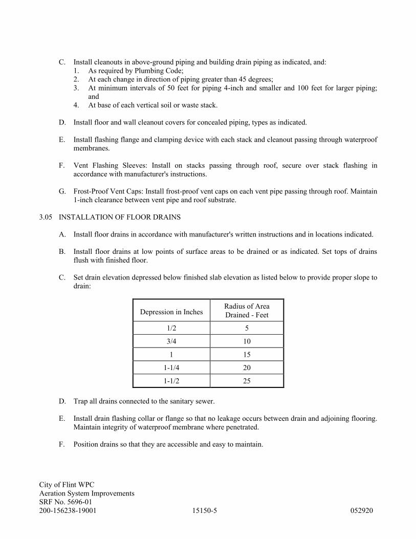
City of Flint WPC
Aeration System Improvements
SRF No. 5696-01
200-156238-19001 15150-5 052920
C. Install cleanouts in above-ground piping and building drain piping as indicated, and:
1. As required by Plumbing Code;
2. At each change in direction of piping greater than 45 degrees;
3. At minimum intervals of 50 feet for piping 4-inch and smaller and 100 feet for larger piping;
and
4. At base of each vertical soil or waste stack.
D. Install floor and wall cleanout covers for concealed piping, types as indicated.
E. Install flashing flange and clamping device with each stack and cleanout passing through waterproof
membranes.
F. Vent Flashing Sleeves: Install on stacks passing through roof, secure over stack flashing in
accordance with manufacturer's instructions.
G. Frost-Proof Vent Caps: Install frost-proof vent caps on each vent pipe passing through roof. Maintain
1-inch clearance between vent pipe and roof substrate.
3.05 INSTALLATION OF FLOOR DRAINS
A. Install floor drains in accordance with manufacturer's written instructions and in locations indicated.
B. Install floor drains at low points of surface areas to be drained or as indicated. Set tops of drains
flush with finished floor.
C. Set drain elevation depressed below finished slab elevation as listed below to provide proper slope to
drain:
Depression in Inches Radius of Area
Drained - Feet
1/2 5
3/4 10
1 15
1-1/4 20
1-1/2 25
D. Trap all drains connected to the sanitary sewer.
E. Install drain flashing collar or flange so that no leakage occurs between drain and adjoining flooring.
Maintain integrity of waterproof membrane where penetrated.
F. Position drains so that they are accessible and easy to maintain.

City of Flint WPC
Aeration System Improvements
SRF No. 5696-01
200-156238-19001 15150-6 052920
3.06 CONNECTIONS
A. Piping Runouts to Fixtures: Provide drainage and vent piping runouts to plumbing fixtures and
drains, with approved trap, of sizes indicated; but in no case smaller than required by the Plumbing
Code.
1. Locate piping runouts as close as possible to bottom of floor slab supporting fixtures or drains.
3.07 FIELD QUALITY CONTROL
A. Inspections:
1. Do not enclose, cover, or put into operation drainage and vent piping system until it has been
inspected and approved by the authority having jurisdiction.
2. During the progress of the installation, notify the plumbing official having jurisdiction at least
24 hours prior to the time such inspection must be made. Perform tests specified below in the
presence of the plumbing official.
3. Rough-in Inspection: Arrange for inspection of the piping system before concealed or closed-in
after system is roughed-in, and prior to setting fixtures.
4. Final Inspection: Arrange for a final inspection by the plumbing official to observe the tests
specified below and to ensure compliance with the requirements of the Plumbing Code.
B. Reinspections: Whenever the piping system fails to pass the test or inspection, make the required
corrections, and arrange for reinspection by the plumbing official.
C. Prepare inspection reports, signed by the plumbing official.
D. Piping System Test: Test drainage and vent system in accordance with the procedures of the
authority having jurisdiction, or in the absence of a published procedure, according to BOCA
Plumbing Code P1702.5.1.
1. Repair all leaks and defects using new materials and retest system or portion thereof until
satisfactory results are obtained.
2. Prepare reports for all tests and required corrective action.
3.08 ADJUSTING AND CLEANING
A. Clean interior of piping system. Remove dirt and debris as Work progresses.
B. Clean drain strainers, domes, and traps. Remove dirt and debris.
3.09 PROTECTION
A. Protect drains during construction period to avoid clogging with dirt and debris and to prevent
damage from traffic and construction work.
B. Place plugs in ends of uncompleted piping at end of day or whenever work stops.
C. Exposed ABS or PVC Piping: Protect plumbing vents exposed to sunlight with two coats of a water-
based latex paint.
END OF SECTION

City of Flint WPC
Aeration System Improvements
SRF No. 5696-01
200-156238-19001 15212-1 052920
SECTION 15212 - COMPRESSED AIR SYSTEMS
PART 1 - GENERAL
1.01 SUMMARY
A. Extent of compressed air systems Work is indicated on Drawings and Schedules and by requirements
of this Section. The standard accessories specified in this Section shall be included as a part of each
single or duplex air supply system.
B. Refer to Division 16 Sections for work, which is not Work of this Section.
1. Power supply wiring from power source to power connection on compressed air equipment.
Include starters, disconnects, and required electrical devices, except where specified as
furnished, or factory-installed, by manufacturer.
2. Interlock wiring between electrically operated compressed air equipment units and between
compressed air equipment and field-installed control devices.
a. Interlock wiring specified as factory-installed is work of this Section.
C. Provide the following electrical work as Work of this Section, complying with requirements of
Division 16.
1. Control wiring between field-installed controls, indicating devices, and unit control panels.
1.02 SUBMITTALS
A. Shop Drawings: Submit in accordance with Section 01330, Shop Drawings covering the items
included under this Section. Shop Drawing submittals shall include:
1. Submit manufacturer's technical product data and installation instructions for compressed air
systems materials and products.
B. Test and Inspection Report: Submit a written report to ENGINEER documenting testing and/or
inspection results. The report shall be prepared as noted under Section 01400.
1.03 QUALITY ASSURANCE
B. Codes and Standards:
1. ASME Compliance: Fabricate and install compressed air piping system in accordance with
ASME B31.9 "Building Services Piping."
2. CAGI Compliance: Provide compressed air auxiliary piping equipment in accordance with
CAGI Standards (Compressed Air and Gas Institute).
3. ASME Compliance: Provide compressed air receivers, and compressed air safety valves in
accordance with ASME "Boiler and Pressure Vessel Code"; provide ASME Code Symbol
Stamp.
4. UL Compliance: Provide electrical components of compressed air system which have been
listed and labeled by UL.

City of Flint WPC
Aeration System Improvements
SRF No. 5696-01
200-156238-19001 15212-2 052920
PART 2 - PRODUCTS
2.01 MANUFACTURERS
A. Subject to compliance with specified requirements, manufacturers offering products which may be
incorporated in Work include:
1. Pressure Regulator and Filter Assemblies:
a. Gardner Denver Co., 65NC403QQ.
b. Wilkerson, B18-03-000.
2. Solenoid Valves:
a. Asco Red Hat II.
b. Double A.
c. Skinner.
3. Particulate Filter:
a. Finite Filter, Grade 3PU.
b. Pall Trinity Micro, Epocel 3.
4. Air Regulator Station:
a. Curtis.
b. DeVilbiss.
c. Fisher.
d. Jordan.
2.02 MATERIALS AND PRODUCTS
A. Provide piping materials and factory-fabricated piping products of sizes, types, pressure ratings,
temperature ratings, and capacities as indicated. Where not indicated, provide proper selection as
determined by installer to comply with installation requirements. Provide sizes and types matching
piping and equipment connections; provide fittings of materials which match pipe materials used in
compressed air systems. Where more than one type of materials or products are indicated, selection
is installer's option.
B. Compressed Air Distribution: Unless otherwise noted, materials for the compressed air distribution
system shall conform to the following specifications. Refer to Section 15105 for piping and Section
15115 for valves listed below:
Acceptable Alternative
Item Spec. No. Specification
Piping 66.1 with Press Fittings
Piping - buried 63.1
Ball Valves 104.8
Check Valves 110.1 110.6
1. Where piping is exposed in chemical, corrosive, or clean areas, or otherwise so specified on
Drawings, materials shall be stainless steel as follows:

City of Flint WPC
Aeration System Improvements
SRF No. 5696-01
200-156238-19001 15212-3 052920
Item Spec. No.
Piping 66.1
Ball Valves 104.8
2. Use 1/4-inch ball valve for gauge cocks.
C. Air Set Assembly: An air set assembly shall be furnished and installed at all locations where high-
pressure air connects to equipment, valve and gate operators, instrumentation panels, and where
shown on Drawings. The air set assembly shall consist of two, 2-way brass ball valves with 3/8-inch
ports, 1/4 turn action and directional handle, and one combination pressure regulator and filter
assembly as specified below. Other instrumentation items shall be furnished with their own air set
assembly under Division 16 and shall be installed under this Section.
1. Pressure Regulator and Filter Assembly: Regulator assembly shall be the diaphragm-operated
type with integral filter, standard mount, 3/8-inch ports and furnished with a 2-inch pressure
gauge, T-handle adjustable screw, and self-venting mechanism. Valve and filter body shall be
die cast aluminum treated and finished with noncorrosive coating, diaphragm and inner valve
shall be Buna-N, spring and adjusting screw shall be cadmium-plated steel. Maximum inlet
pressure shall be 150 psi, operating inlet pressure shall be at least 80 psi, and reduced pressure
range shall be from 0-125 psi as indicated on Drawings. Diaphragm head shall have a built-in
relief valve which will open at a pressure 1 psi over the spring setting. Filter element shall be
laminated phenolic resin. An automatic drain shall be provided in the bottom of the
accumulator.
2.03 BASIC PIPING SPECIALTIES
A. Provide piping specialties complying with Section 15050, in accordance with the following listing:
1. Pipe escutcheons.
2. Dielectric unions.
3. Pipe sleeves.
4. Sleeve seals.
2.04 BASIC SUPPORTS AND ANCHORS
A. Provide supports and anchors complying with Section 15060.
2.05 PRESSURE GAUGES
A. Provide gauges complying with Section 15125, in accordance with the following listing:
1. Pressure gauges and fittings.
2.06 STANDARD ACCESSORIES
A. Provide the following accessory items for each air supply system: air regulator station, and trapsThe
size and capacity of each accessory item shall be sufficient to handle the total capacity of the
compressor system specified.
B. Quick Disconnect: 200 PSIG working pressure zinc plated steel or brass body and Buna-N seal. Sleeve type,
single shut off NPT inlet x 1/4” coupler unless noted otherwise. Provide 3/8” coupler where noted. Coupler
design shall be compatable with ARO 210, Industrial Interchange and Tru-Flate plugs. MIL C-4109

City of Flint WPC
Aeration System Improvements
SRF No. 5696-01
200-156238-19001 15212-4 052920
C. Air Regulator Stations: Air regulator station shall consist of a combination pressure-reducing valve
and downstream pressure gauge. The capacity of the pressure-reducing valve shall be equal to the
output of both compressors and shall be rated for maintaining a downstream pressure of 40 to 80 psi
with air upstream pressure as supplied by the specified compressor.
D. A pressure relief valve shall be provided at the discharge of each compressor as a safety valve. The
valve shall be ASME rated.
PART 3 - EXECUTION
3.01 INSPECTION
A. Examine areas and conditions under which compressed air systems and equipment is to be installed.
Do not proceed with Work until unsatisfactory conditions have been corrected in manner acceptable
to Installer.
3.02 INSTALLATION OF COMPRESSED AIR PIPING
A. Install compressed air piping in accordance with Section 15105.
B. Install piping with 1/8-inch per foot (1 percent) downward slope in direction of air flow.
C. Install reducers where required.
D. Connect branch piping to mains from top of main. Provide drain leg and drain trap at end of each
main, each branch, and each low point in piping system.
3.03 INSTALLATION OF PIPING SPECIALTIES
A. Install piping specialties in accordance with Section 15105.
3.04 INSTALLATION OF SUPPORTS AND ANCHORS
A. Install supports and anchors in accordance with Section 15060.
B. Spacing: Do not exceed 10'-0" spacing between pipe hangers for any size pipe.
3.05 INSTALLATION OF VALVES
A. Install valves in accordance with Section 15115.
3.06 INSTALLATION OF GAUGES
A. Install gauges in accordance with Section 15125.

City of Flint WPC
Aeration System Improvements
SRF No. 5696-01
200-156238-19001 15212-5 052920
3.07 EQUIPMENT CONNECTIONS
A. Connect compressed air piping system to mechanical equipment as indicated, and comply with
equipment manufacturer's instructions where not otherwise indicated.
3.08 FIELD QUALITY CONTROL
A. Compressed Air Piping Leak Test: Prior to initial operation of piping system, air purge lines with oil-
free dry air, and perform 24-hour standing pressure time-test. Charge line with compressed air to 150
psi; maintain test pressure for 24-hours with pressure loss no greater than 5 psi. During pressure test,
test joints and fittings for leaks with soap bubble solution; while bubble testing, hammer joints with
rubber or rawhide mallet to break hardened flux.
B. Repair or replace compressed air piping as required to eliminate leaks, and retest as specified to
demonstrate compliance.
C. Cap (seal) ends of piping where not connected to mechanical equipment.
3.09 ADJUSTING AND CLEANING
A. Clean, flush, and inspect compressed air systems in accordance with requirements of Section 15105.
B. Installation Check: The manufacturer shall provide the services of a factory-trained representative to
check the installation of all equipment installed in this Section. The services shall be as noted in
Section 01600.
END OF SECTION

City of Flint WPC
Aeration System Improvements
SRF No. 5696-01
200-156238-19001 16050-1 052920
SECTION 16050 - BASIC ELECTRICAL REQUIREMENTS
PART 1 - GENERAL
1.01 SUMMARY
A. Section Includes: General administrative, procedural requirements, and installation methods for
electrical installations specified in Division 16.
B. The Drawings are schematic and are not intended to show every detail of construction.
1. In general, conduits/raceways, transitions and offsets shown on Drawings indicate approximate
locations in plan and elevation where the systems are intended to be run.
2. CONTRACTOR shall fully coordinate electrical Work with other trades to avoid interferences.
3. In the event of interferences, CONTRACTOR shall request clarification from ENGINEER in
writing.
B. Related Documents: Drawings and general provisions of Contract, including General and
Supplementary Conditions and Division 1 Sections, apply to Work of this Section.
1.02 SUBMITTALS
A. Shop Drawings: Submit in accordance with requirements of Section 01330, Shop Drawings covering
the items included under this Section of Work. Shop Drawing submittals shall include:
1. Submit product data covering the items included under this Section of Work.
B. Conforming to Construction Drawings: Submit a complete set of Drawings showing the locations of
the piping, ductwork, etc., as actually installed. Such Drawings shall be submitted to ENGINEER on
tracing cloth, Mylar, or sepia paper from which blueprints can be obtained.
C. Operation and Maintenance Manuals: Submit in accordance with requirements of Section 01600,
operation and maintenance manuals for items included under this Section. Include following
information for equipment items:
1. Description of function, normal operating characteristics and limitations, performance curves,
engineering data and tests, and complete nomenclature and commercial numbers of replacement
parts.
2. Manufacturer's printed operating procedures to include start-up, break-in, and routine and
normal operating instructions; regulation, control, stopping, shutdown, and emergency
instructions; and summer and winter operating instructions.
3. Maintenance procedures for routine preventative maintenance and troubleshooting;
disassembly, repair, and reassembly; aligning and adjusting instructions.
4. Servicing instructions and lubrication charts and schedules.
1.03 RECORD DOCUMENTS
A. Prepare Record Documents in accordance with requirements in Section 01770. In addition,
CONTRACTOR shall submit, prior to final payment, Drawings conforming to construction records
of systems it has installed. Vendor drawings shall be sized as manufacturers' standard.

City of Flint WPC
Aeration System Improvements
SRF No. 5696-01
200-156238-19001 16050-2 052920
B. Provide typewritten data sheets on motor control circuits with following information on each branch
feeder: Load name, horsepower or KVA (transformer), fuse size, starter size, service factor of motor,
motor nameplate currents, power factor correction capacitor size (if used), and thermal overload part
number.
1.04 QUALITY ASSURANCE
A. National Electrical Code: Comply with NFPA 70, National Electrical Code.
B. UL Compliance and Labeling: Use products and components labeled by UL.
1.05 PERMITS, INSPECTIONS, AND LICENSES
A. CONTRACTOR shall procure all necessary permits and licenses, observe and abide by all applicable
laws, codes, regulations, ordinances, and rules of the State, territory, or political subdivision thereof,
wherein Work is done, or any other duly constituted public authority, and further agrees to hold
OWNER harmless from liability or penalty which might be imposed by reason of an asserted
violation of such laws, codes, regulations, ordinances, or other rules.
1. Upon completion of Work, CONTRACTOR shall secure certificates of inspection from the
inspector having jurisdiction and shall submit 3 copies of the certificates to OWNER.
CONTRACTOR shall pay the fees for the permits, inspections, licenses, and certifications when
such fees are required.
1.06 DELIVERY, STORAGE, AND HANDLING
A. Deliver products to Project properly identified with names, model numbers, types, grades,
compliance labels, and other information needed for identification. Equipment shall be packaged to
prevent damage during shipment, storage, and handling. Do not install damaged units; replace, and
remove damaged units from Site.
PART 2 - PRODUCTS
2.01 AMMETER
A. Furnish for OWNER's use an Amprobe, Model ACD-4, digital clamp-on ammeter.
PART 3 - EXECUTION
3.01 GENERAL ELECTRICAL INSTALLATION
A. Provide electrical materials and equipment enclosures appropriate for areas in which they are
installed. Each area will be designated on Drawings with a type of construction such as NEMA 4,
4X, 7 or 9 if it is other than NEMA 12. An area designated by a name and elevation includes space
bounded by floor, ceiling, and enclosing walls.
1. Exception: Provide manufacturer's standard construction for indoor or outdoor application
where equipment is not manufactured to NEMA specifications (e.g., switchgear, transformers,
high voltage capacitors, bus duct, and light fixtures; materials and equipment used in finished
areas such as offices, laboratories, etc.).
City of Flint WPC
Aeration System Improvements
SRF No. 5696-01
200-156238-19001 16050-3 052920
B. Provide nonmetallic electrical materials and equipment enclosures in NEMA 4X areas; watertight
NEMA 4 and equipment enclosures for outdoor applications and indoor applications below grade;
explosion-proof NEC Class I, Division 1, Group C and Group D equipment for NEMA 7 areas;
explosion-proof NEC Class II, Division 2, Group F equipment for NEMA 9 areas.
C. Coordinate with power company high voltage and/or low voltage metering requirements. Furnish,
install, and connect metering equipment not furnished, installed or connected by power company.
D. Coordinate with telephone company the communication service requirements. Furnish, install, and
connect cable and terminal equipment not furnished, installed, or connected by telephone company.
Furnish and install a 4-foot by 8-foot by 3/4-inch plywood backboard painted white, raceway from
backboard to property line, and cross-connect base and blocks which utilize punchdown wiring
methodology.
E. Provide chases, slots, and openings in other building components during progress of construction, to
allow for electrical installations.
F. Supporting devices and sleeves shall be set in poured-in-place concrete and other structural
components as they are constructed.
G. Where mounting heights are not detailed or dimensioned, install systems, materials, and equipment
to provide maximum headroom possible. Locate light fixtures at approximately 8 feet above floor
and where fixtures may be readily serviced.
H. Coordinate connection of electrical systems with exterior underground and overhead utilities and
services. Comply with requirements of governing regulations, franchised service companies, and
controlling agencies. Provide required connection for each service.
I. Install systems, materials, and equipment to conform with approved submittal data, including
coordination Drawings, to greatest extent possible. Conform to arrangements indicated by Drawings
recognizing that portions of Work are shown only in diagrammatic form. Where coordination
requirements conflict with individual system requirements, refer conflict to ENGINEER.
J. Install systems, materials, and equipment level and plumb, parallel and perpendicular to other
building systems and components where installed exposed in finished spaces.
K. As much as practical, connect equipment for ease of disconnecting with minimum of interference
with other installations.
L. Install access panel or doors where units are concealed behind finished surfaces.
M. Install systems, materials, and equipment giving right-of-way priority to systems required to be
installed at a specified slope.
3.02 RACEWAY INSTALLATION
A. Outdoors, use the following materials:
1. Exposed Conduit: PVC externally coated rigid metal conduit and fittings.
2. Underground Direct Buried Conduit: PVC externally coated rigid metal conduit.

City of Flint WPC
Aeration System Improvements
SRF No. 5696-01
200-156238-19001 16050-4 052920
3. Underground Concrete Encased Conduit: Fiberglass-reinforced conduit or rigid nonmetallic
conduit if the conductors are used for power or 120 VAC; otherwise, use rigid metal conduit.
4. Conduit Used to Connect to Vibrating Equipment including transformers and hydraulic,
pneumatic or electric solenoid or motor-driven equipment: Liquidtight flexible metal conduit.
B. Indoors, use the following wiring materials:
1. Connection to Vibrating Equipment, including transformers and hydraulic, pneumatic or electric
solenoid or motor-operated equipment: Liquidtight flexible metal conduit.
a. Exception: NEMA 7 or 9 areas require explosion-proof flexible conduit.
2. Exposed Conduit(Nema 12 and Nema 4 areas): PVC externally coated rigid metal conduit or
aluminum conduit.
a. Exceptions:
1) Areas indicated as NEMA 4X, use rigid Schedule 80 PVC conduit.
2) Areas indicated as NEMA 7 or NEMA 9 (such as grit and raw sewage rooms), use
PVC externally coated rigid metal conduit.
3. Concealed Conduit: Rigid metal conduit or aluminum conduit unless indicated otherwise.
C. Minimum size conduit shall be 1 inch unless shown otherwise.
D. Instrument Signal Conduit Requirements: Shielded signal wires for 4-20 mA type instruments or
thermocouple wires assigned to the same control panel may be run in the same conduit. Shielded
instrument signal wires, thermocouple wires, and shielded 2-wire intercom wires may be run in the
same conduit. No other wires will be permitted in an instrument signal/2-wire intercom conduit.
Conduit shall be RMC or PVC-coated RMC.
E. Conduit Thread Paint: Make threaded conduit joints watertight by coating threaded portions with a
spray-on or brush-on zinc-bearing paint. Provide paint containing 90 percent minimum by weight of
metallic zinc powder in the dried film. Clean field-cut threads of oil using the recommended solvent
prior to coating threads.
F. Install expansion fittings in all exposed rigid nonmetallic conduit runs of 20 feet or more.
G. Install expansion/deflection fittings where conduit passes a building expansion joint or where
conduits are attached to two structures joined by a concrete expansion joint.
H. Exposed or Concealed Construction: Install conduit exposed inside buildings except for areas with
finished walls (e.g., offices, laboratories, lavatories, locker rooms, etc.) unless otherwise indicated.
I. Concealed Raceways: Raceways embedded in slabs shall be installed in the middle third of the slab
thickness where practical and leave at least 1-inch concrete cover. Tie raceways to reinforcing rods
or otherwise secure them to prevent sagging or shifting during concrete placement. Space raceways
laterally to prevent voids in the concrete. Run 1-inch and smaller raceways with a minimum of bends
in the shortest practical distance. Run larger conduit parallel with or at right angles to the main
reinforcement; where at right angles to the reinforcement, the conduit shall be close to one of the
supports of the slab. Where nonmetallic conduit or fiberglass-reinforced conduit is used, raceways
must be converted to PVC externally coated rigid metal conduit before rising above floor.
J. Exposed Raceways: Install parallel and perpendicular to nearby surfaces or structural members and
follow the surface contours as much as practical. Make bends and offsets so the inside diameter is
not effectively reduced. Keep the legs of a bend in the same plane and the straight legs of offsets

City of Flint WPC
Aeration System Improvements
SRF No. 5696-01
200-156238-19001 16050-5 052920
parallel. Conduits shall slope away from loads to keep moisture from entering the load. Run parallel
or banked raceways together. Make bends in parallel or banked runs from the same centerline so that
the bends are parallel. Factory elbows may be used in banked runs only where they can be installed
parallel. This requires that there be a change in the plane of the run, such as from wall to ceiling and
that the raceways be of the same size. In other cases, provide field bends for parallel raceways. Keep
raceways at least 6 inches away from parallel runs of flues and steam or hot water pipes. Install
horizontal raceway runs above water and steam piping.
K. Space raceways, fittings, and boxes 0.25 inch from mounting surface in NEMA 4 and NEMA 7
areas. Spacers shall be one-piece construction of stainless steel, galvanized steel, PVC, ABS, or other
noncorrosive material.
L. Sleeves: Install in concrete floor slabs except where conduit passes through a housekeeping pad.
Install in exterior walls below grade.
M. Stub-up Connections: Extend conduits through concrete floor for connection to freestanding
equipment with an adjustable top or coupling threaded inside for plugs and set flush with the finished
floor. Extend conductors to equipment with rigid metal conduit; flexible metal conduit may be used
6 inches above the floor. Where equipment connections are not made under this Contract, install
screwdriver-operated threaded flush plugs with floor.
N. Flexible Connections: Use short length (maximum 6 feet for lighting fixtures; maximum 3 feet for all
other equipment) of flexible conduit for recessed and semi-recessed lighting fixtures, equipment
subject to vibration, noise transmission, or movement, and all motors. Use liquidtight flexible
conduit in wet locations and rated flexible connections for hazardous locations. Install separate
ground conductor across flexible connections.
O. Join raceways with fittings designed and approved for the purpose and make joints tight. Where
joints cannot be made tight, use bonding jumpers to provide electrical continuity of the raceway
system. Where terminations are subject to vibration, use bonding bushings or wedges to assure
electrical continuity. Where subject to vibration or dampness, use insulating bushings to protect
conductors.
P. Use raceway fittings that are of types compatible with the associated raceway and suitable for the use
and location. For intermediate metal conduit, use threaded rigid metal conduit fittings. For PVC
externally coated rigid metal conduit, use only factory-coated fittings approved for use with that
material. Patch all nicks and scrapes in PVC coating after installing conduit.
Q. Install raceway sealing fittings in accordance with the manufacturer's written instructions. Locate
fittings at suitable, approved, accessible locations and fill them with UL listed sealing compound.
For concealed raceways, install each fitting in a flush metal box with a blank cover plate having a
finish similar to that of adjacent plates or surfaces. Install raceway sealing fittings at the following
points and elsewhere as indicated:
1. Where conduits enter or leave hazardous locations.
2. Where conduits enter or leave NEMA 4X areas.
3. Where conduits pass from warm locations to cold locations, such as the boundaries of
refrigerated spaces and air-conditioned spaces.
4. Where required by the NEC.
5. Where noted on drawings.

City of Flint WPC
Aeration System Improvements
SRF No. 5696-01
200-156238-19001 16050-6 052920
R. Install electrical boxes in those locations which ensure ready accessibility to enclosed electrical
wiring. Provide knockout closures to cap unused knockout holes where blanks have been removed.
S. Install device boxes at the height above the floor as follows for:
1. Light switches, 4 feet.
2. Receptacles and telephone jacks, 18 inches except in NEMA 4 and 4X areas, 4 feet.
3. Thermostats, 4'-0".
4. Clock receptacles, 7'-0".
T. Avoid installing boxes back-to-back in walls. Provide not less than 6-inch (150 mm) separation.
U. Position recessed outlet boxes accurately to allow for surface finish thickness.
V. Fasten electrical boxes firmly and rigidly to substrates or structural surfaces to which attached, or
solidly embed electrical boxes in concrete masonry.
W. Provide fire-retardant barriers in all pull and junction boxes containing circuits that are otherwise
continuously separated in conduit. Securely fasten these barriers within box. Size barriers so that
space between barrier and box wall does not exceed 0.125 inch anywhere around the perimeter of
barrier.
X. Support exposed raceway within 1 foot of an unsupported box and access fittings. In horizontal runs,
support at box and access fittings may be omitted where box or access fittings are independently
supported and raceway terminals are not made with chase nipples or threadless box connectors.
Y. In open overhead spaces, cast boxes threaded to raceways need not be supported separately except
where used for fixture support; support sheet metal boxes directly from building structure.
Z. Terminations: Where raceways are terminated with locknuts and bushings, align the raceway to enter
squarely and install the locknuts with dished part against the box. Where terminating in threaded
hubs, screw the raceway or fitting tight into the hub so the end bears against the wire protection
shoulder. Where chase nipples are used, align the raceway so the coupling is square to the box and
tighten the chase nipples so no threads are exposed.
AA. Complete installation of electrical raceways before starting installation of conductors within
raceways and prevent foreign matter from entering raceways by using temporary closure protection.
Cap spare conduit. Protect stub-ups from damage where conduits rise from floor slabs. Arrange so
curved portion of bends is not visible above the finished slab.
BB. Install pull wires in empty raceways: Use No. 14 AWG zinc-coated steel or monofilament plastic
line having not less than 200-pound tensile strength. Leave not less than 12 inches of slack at each
end of the pull wire.
3.03 WIRE AND CABLE INSTALLATION
A. Use pulling means including fish tape, cable, rope, and basket weave wire/cable grips which will not
damage cables or raceways. Pull conductors simultaneously where more than one is being installed
in same raceway. Use UL listed pulling compound or lubricant where necessary.

City of Flint WPC
Aeration System Improvements
SRF No. 5696-01
200-156238-19001 16050-7 052920
B. Keep branch circuit conductor splices to minimum. Splice feeders only where indicated. Use a
standard kit. No splices are allowed for instrument and telephone cables except at indicated splice
points.
C. Install splice and tap connectors which possess equivalent or better mechanical strength and
insulation rating than conductors being spliced. Use splice and tap connectors which are compatible
with conductor material and are UL listed as pressure type connectors.
D. Provide adequate length of conductors within electrical enclosures and train conductors to terminal
points with no excess. Bundle multiple conductors, with conductors larger than No. 10 AWG cabled
in individual circuits. Make terminations so there is no bare conductor at terminal.
E. Terminate power conductors at equipment using pressure-type terminals specifically designed for
type of terminations to be made. Terminate no more than 2 conductors No. 8 AWG and smaller
within the same pressure-type terminal. These 2 conductors shall be no more than 4 wire gauge sizes
apart. Terminate no more than 1 conductor larger than No. 8 AWG within any pressure-type
terminal.
1. Exception: Power factor correction capacitor conductors may be terminated at the motor
disconnect switch load terminals.
F. Seal wire and cable ends until ready to splice or terminate.
3.04 CUTTING AND PATCHING
A. Perform cutting and patching in accordance with requirements in Section 01730. In addition, the
following requirements apply.
1. Perform cutting, fitting, and patching of electrical equipment and materials required to uncover
Work to provide for installation of ill-timed Work, remove and replace Work that is either
defective or does not conform to requirements of Drawings.
2. Cut, remove, and legally dispose of selected electrical equipment, components, and materials as
indicated including, but not limited to, removal of electrical items indicated to be removed and
items made obsolete by new Work. Protect structure, furnishings, finishes, and adjacent
materials not indicated or scheduled to be removed. Provide and maintain temporary partitions
or dust barriers adequate to prevent spread of dust and dirt to adjacent areas.
3. Patch existing finished surfaces and building components using new materials matching
existing materials.
3.05 EQUIPMENT CHECKOUT AND TESTING
A. In addition to testing recommended by equipment or material supplier and called for in equipment or
material specification, perform the following.
B. Motor Testing: Motor insulation shall be tested by using a 500 VDC (minimum) megger and
applying test until a constant megohm reading of the following magnitude is obtained:
Rmin. = 4 (KV + 1) at 25 degrees C winding temp. Rmin. = IV + 1 at 40 degrees C winding temp.
1. If motors do not meet requirements of megger test, blow hot air through motors to dry out and
repeat until test is passed. If desirable, drying can be done by applying an electrical potential to
City of Flint WPC
Aeration System Improvements
SRF No. 5696-01
200-156238-19001 16050-8 052920
equipment. However, in no case, induced or direct, shall voltage or current exceed continuous
rating of equipment being dried.
2. After passing megger test, motors shall be hi-pot tested at 200 percent rated voltage for a
minimum of 1 minute.
C. Equipment Testing: The following tests which are applicable for a particular item of equipment shall
be performed:
1. Megger bus work phase-to-phase and phase-to-ground. Minimum acceptable steady-state value
is 100 megohms.
2. Megger power circuit breakers and circuits supplied phase-to-phase and phase-to-ground
(100 megohms minimum).
3. Test current transformer circuits by applying current to secondary wiring at current transformer
terminals until contactor trips.
4. Test, time, and set protective relays. Relays shall be timed at various multiples (minimum of
3 points) of the pick-up value to determine agreement with published curves and adjust as
necessary to agree with coordination study required settings. Exact tests to be performed vary
with type of relay. Manufacturer's instructions for relay shall be complied with.
5. After Work has been completed, demonstrate to OWNER's Representative that entire electrical
installation is in proper working order and will perform functions for which it was designed by
functional testing.
6. Make any specific tests required by the manufacturer's installation instructions.
D. Check-out Procedures. In general, check-out procedures (as listed below) which are applicable for a
particular item of equipment shall be performed:
1. Vacuum interior of cubicles and remove foreign material.
2. Wipe clean with a lint-free cloth insulators, bushings, bus supports, etc.
3. Check and adjust time delay, under-voltage devices, phase relay, over-current relays, etc., as
required by coordination study or ENGINEER.
4. Fill motor bearings requiring oil.
5. Check and change, as required, thermal overload heater elements to correspond with motor full-
load current and service factors of installed motor.
6. Check direction of rotation of motors and reverse connections if necessary. Check rotation with
motor mechanically uncoupled where reverse rotation could damage equipment.
7. Equipment with two or more sources of power connected by tie breakers, transfer switches, or
generator receptacles shall be checked for rotation from each possible combination of power
sources. Power sources must have the same phase sequence for each source throughout entire
facility.
8. Check exposed bolted power connections for tightness.
9. Check operation of breakers, contactors, etc., and control and safety interlocks.
10. Check tightness of bolted structural connections.
11. Check leveling and alignment of enclosures.
12. Check operating parts and linkages for lubrication, freedom from binding, vibration, etc.
13. Check tightness and correctness of control connections at terminal blocks, relays, meters,
switches, etc.
14. Clean auxiliary contacts and exposed relay contacts after vacuuming.
END OF SECTION

City of Flint WPC
Aeration System Improvements
SRF No. 5696-01
200-156238-19001 16052-1 052920
SECTION 16052- COORDINATION STUDY AND ARC FLASH ANALYSIS
PART 1 - GENERAL
1.01 SUBMITTALS
A. Coordination Study detailing electrical system protection, protective equipment selectivity and arc
flash hazard analysis studies shall be performed for this project.
B. Submit electronic copies of the SKM raw data software files(the files created by the SKM software).
The reports shall include the following sections:
a. One-line diagram showing protective device ampere ratings and associated designations,
cable size & lengths, transformer kVA & voltage ratings, motor & generator kVA ratings,
and switchgear/switchboard/panelboard designations
b. Descriptions, purpose, basis and scope of the study
c. Tabulations of the worst-case calculated short circuit duties as a percentage of the applied
device rating (automatic transfer switches, circuit breakers, fuses, etc.); the short circuit
duties shall be upward-adjusted for X/R ratios that are above the device design ratings
d. Protective device time versus current coordination curves with associated one line diagram
identifying the plotted devices, tabulations of ANSI protective relay functions and
adjustable circuit breaker trip unit settings
e. Fault study input data, case descriptions, and current calculations including a definition of
terms and guide for interpretation of the computer printout
f. Incident energy and flash protection boundary calculations
g. Comments and recommendations for system improvements, where needed
h. Executive Summary including source of information and assumptions made
1.02 COORDINATION STUDY
A. Include as part of Contract a complete Coordination and Short Circuit Study from incoming power
lines primary switches and transformers through the high voltage switchgear, unit substations, and
the motor control centers branch circuits for the new work shown this contract. This includes new
medium voltage equipment and circuit breakers installed within existing motor control centers.
Obtain available short circuit current, inrush current, and upstream protective device time current
curves from the power company. Include power company current data and protective device curve as
part of study. Study shall include all coordinating curves with each fuse size, trip settings, and
thermal overloads given for connected loads. Curves shall include feeder wire melting curves and
transformer ANSI rating points. The study shall also include variable frequency drives harmonic
filters, power factor correction equipment, transformers and protective devices associated with
variable frequency drives, emergency and standby generators associated paralleling equipment and
distribution switchgear. Fuse sizes on motor control centers shall be those shown in Drawings
throughout the short circuit and coordination study. Changes in loads from those shown on Drawings
shall be incorporated in Study.
B. Analysis and labeling shall include the existing motor control centers as well as the new motor
control centers and medium voltage equipment shown on the contract drawings.

City of Flint WPC
Aeration System Improvements
SRF No. 5696-01
200-156238-19001 16052-2 052920
C. Contractor shall furnish all field data as required for the power system studies and arc flash hazard
analysis studies. Include fault contribution of existing motors in the study, with motors < 50 hp
grouped together. The Contractor shall obtain required existing equipment data, if necessary, to
satisfy the study requirements.
D. Study/report shall be performed by Eaton, General Electric, Rockwell, or Square D. Study results
shall be submitted to ENGINEER for approval. Report shall be stamped by a licensed professional
electrical engineer in the state of Michigan. Final report shall include the SKM raw data files to be
turned over to Owner.
E. After approval all electrical equipment settings, thermal overloads, and fuses shall be made to
conform to approved results. CONTRACTOR shall test all trip settings, time delays, and indicating
devices on all switchgear, unit substations, and motor control centers. Tests shall be witnessed by
ENGINEER.
F. Data sheets for test are to be furnished by CONTRACTOR and shall be filled out showing the
desired settings from Coordination Study and results obtained from witnessed test. Data sheets shall
be signed by those performing test and witness. Test data sheets and motor list showing fuses,
thermal overload sizes, etc. shall be submitted to ENGINEER as part of Contract.
PART 2 - PRODUCTS
2.01 SHORT-CIRCUIT AND PROTECTIVE DEVICE EVALUATION STUDY
A. Use actual conductor impedances if known. If unknown, use typical conductor impedances based on
IEEE Standards 141, latest edition. Transformer design impedances and standard X/R ratios shall be
used when test values are not available.
B. Provide the following information in the study report:
1. Calculation methods and assumptions.
2. Base per unit quantities.
3. One-line diagram of the system being evaluated with available fault at each bus, and interrupting
rating of devices noted.
4. Source impedance data, including electric utility system and motor fault contribution
characteristics.
5. Typical calculations and tabulations of calculated quantities.
6. Results, conclusions, and recommendations.
C. Calculate short-circuit momentary and interrupting duties for a three-phase bolted fault at each:
1. Electric utility’s supply termination point.
2. Incoming switchgear.
3. Unit substation primary and secondary terminals.
4. Low voltage switchgear.
5. Motor control centers.
6. Standby generators and automatic transfer switches.
7. Branch circuit panelboards.
8. Other significant locations throughout the system.

City of Flint WPC
Aeration System Improvements
SRF No. 5696-01
200-156238-19001 16052-3 052920
D. On grounded systems, provide a bolted line-to-ground fault current study for areas as defined for the
three-phase bolted fault short-circuit study.
E. Protective Device Evaluation:
1. Evaluate equipment and protective devices and compare to short circuit ratings.
2. Adequacy of switchgear, motor control centers, and panelboard bus bracing to withstand short-
circuit stresses.
3. Adequacy of transformer windings to withstand short-circuit stresses.
4. Cable and busway sizes for ability to withstand short-circuit heating.
5. Notify Owner in writing, of existing circuit protective devices improperly rated for the calculated
available fault current.
2.02 PROTECTIVE DEVICE COORDINATION STUDY
A. Proposed protective device coordination time-current curves shall be graphically displayed on log-
log scale paper.
B. Include on each curve sheet a complete title and one-line diagram with legend identifying the
specific portion of the system covered.
C. Terminate device characteristic curves at a point reflecting maximum symmetrical or asymmetrical
fault current to which device is exposed.
D. Identify device associated with each curve by manufacturer type, function, and, if applicable, tap,
time delay, and instantaneous settings recommended.
E. Plot the following characteristics on the curve sheets, where applicable:
1. Electric utility’s protective device
2. Medium voltage equipment relays
3. Medium and low voltage fuses including manufacturer’s minimum melt, total clearing, tolerance,
and damage bands
4. Low voltage equipment circuit breaker trip devices, including manufacturer’s tolerance bands
5. Transformer full-load current, magnetizing inrush current, and ANSI transformer withstand
parameters
6. Conductor damage curves
7. Ground fault protective devices, as applicable
8. Pertinent motor starting characteristics and motor damage points
9. Pertinent generator short-circuit decrement curve and generator damage point
10. Other system load protective devices for the largest branch circuit and the largest feeder circuit
breaker in each motor control center
F. Provide adequate time margins between device characteristics such that selective operation is
provided, while providing proper protection.
2.03 ARC FLASH HAZARD ANALYSIS
A. The arc flash hazard analysis shall be performed according to the IEEE 1584 equations that are
presented in NFPA70E-2004, Annex D.

City of Flint WPC
Aeration System Improvements
SRF No. 5696-01
200-156238-19001 16052-4 052920
B. When appropriate, the short circuit calculations and the clearing times of the phase overcurrent
devices will be retrieved from the short-circuit and coordination study model.
C. The flash protection boundary and the incident energy shall be calculated at all significant locations
in the electrical distribution system (switchboards, switchgear, motor-control centers, panelboards,
busway and splitters) where work could be performed on energized parts.
D. The Arc-Flash Hazard Analysis shall include all medium voltage and 480v locations and significant
locations in 240 volt and 208 volt systems fed from transformers equal to or greater than 125 kVA.
E. Safe working distances shall be specified for calculated fault locations based upon the calculated arc
flash boundary considering an incident energy of 1.2 cal/cm2.
F. The Arc Flash Hazard analysis shall include calculations for maximum and minimum contributions
of fault current magnitude. The minimum calculation shall assume that the utility contribution is at a
minimum and shall assume a minimum motor load. Conversely, the maximum calculation shall
assume a maximum contribution from the utility and shall assume motors to be operating under full-
load conditions.
G. Arc flash computation shall include both line and load side of main breaker calculations, where
necessary.
H. Arc Flash calculations shall be based on actual overcurrent protective device clearing time.
Maximum clearing time will be capped at 2 seconds based on IEEE 1584-2002 section B.1.2.
2.04 REPORT SECTIONS
A. Input Data:
1. Utility three-phase and line-to-ground available contribution with associated X/R ratios
2. Short-circuit reactance of rotating machines with associated X/R ratios
3. Cable type, construction, size, # per phase, length, impedance and conduit type
4. Bus duct type, size, length, and impedance
5. Transformer primary & secondary voltages, winding configurations, kVA rating, impedance, and
X/R ratio
6. Reactor inductance and continuous ampere rating
7. Aerial line type, construction, conductor spacing, size, # per phase, and length
B. Short-Circuit Data:
1. Source fault impedance and generator contributions
2. X to R ratios
3. Asymmetry factors
4. Motor contributions
5. Short circuit kVA
6. Symmetrical and asymmetrical fault currents
C. Recommended Protective Device Settings:
1. Phase and Ground Relays:
a. Current transformer ratio.
b. Current setting.

City of Flint WPC
Aeration System Improvements
SRF No. 5696-01
200-156238-19001 16052-5 052920
c. Time setting.
d. Instantaneous setting.
e. Specialty non-overcurrent device settings.
f. Recommendations on improved relaying systems, if applicable.
2. Circuit Breakers:
a. Adjustable pickups and time delays (long time, short time, ground).
b. Adjustable time-current characteristic.
c. Adjustable instantaneous pickup.
d. Recommendations on improved trip systems, if applicable.
D. Incident energy and flash protection boundary calculations.
1. Arcing fault magnitude
2. Device clearing time
3. Duration of arc
4. Arc flash boundary
5. Working distance
6. Incident energy
7. Hazard Risk Category
8. Recommendations for arc flash energy reduction
PART 3 – EXECUTION
3.01 ARC FLASH WARNING LABELS
A. The CONTRACTOR shall provide a 3.5 in. x 5 in. thermal transfer type label of high adhesion
polyester for each work location analyzed.
B. The label shall have an orange header with the wording, “WARNING, ARC FLASH HAZARD”,
and shall include the following information:
1. Location designation
2. Nominal voltage
3. Flash protection boundary
4. Hazard risk category
5. Incident energy
6. Working distance
7. Engineering report number, revision number and issue date
C. Arc flash labels shall be provided in the following manner and all labels shall be based on
recommended overcurrent device settings.
1. For each 600, 480 and applicable 208 volt panelboards and disconnects, one arc flash label shall
be provided.
2. For each motor control center, two arc flash labels shall be provided, one at each end of the motor
control center.
3. For each low voltage switchboard, one arc flash label shall be provided
4. For each switchgear or unit substations, two arc flash labels shall be provided, one at each end of
the equipment or near each main breaker.
5. For each medium voltage switch, one arc flash label shall be provided.

City of Flint WPC
Aeration System Improvements
SRF No. 5696-01
200-156238-19001 16052-6 052920
D. Labels shall be field installed by the electrical supplier performing the studies, local power company,
or engineering service division of the equipment manufacturer during the Startup and Acceptance
Testing.
3.02 ARC FLASH TRAINING
A. The equipment vendor shall train personnel of the potential arc flash hazards associated with
working on energized equipment (minimum of 16 hours, two trips to the Owners facility).
Maintenance procedures in accordance with the requirements of NFPA 70E, Standard for Electrical
Safety Requirements for Employee Workplaces, shall be provided in the equipment manuals. The
training shall be certified for continuing education units (CEUs) by the International Association for
Continuing Education Training (IACET). Assume for twenty (20) individuals of the Owners staff to
be trained.
END OF SECTION

City of Flint WPC
Aeration System Improvements
SRF No. 5696-01
200-156238-19001 16060-1 052920
SECTION 16060 - GROUNDING
PART 1 - GENERAL
1.01 SUMMARY
A. Section Includes: Electrical grounding and bonding Work as follows:
1. Solidly grounded.
B. Applications of electrical grounding and bonding Work in this Section:
1. Underground metal piping.
2. Underground metal water piping.
3. Underground metal structures.
4. Metal building frames.
5. Electrical power systems.
6. Grounding electrodes.
7. Separately derived systems.
8. Raceways.
9. Service equipment.
10. Enclosures.
11. Equipment.
12. Lighting standards.
13. Landscape lighting.
14. Signs.
1.02 SUBMITTALS
A. Shop Drawings: Submit in accordance with Section 01330, Shop Drawings covering the items
included under this Section. Shop Drawing submittals shall include:
1. Product Data: Submit manufacturer's data on grounding and bonding products and associated
accessories.
1.03 QUALITY ASSURANCE
A. Codes and Standards:
1. UL Compliance: Comply with applicable requirements of UL Standards No. 467, "Electrical
Grounding and Bonding Equipment," and No. 869, "Electrical Service Equipment," pertaining
to grounding and bonding of systems, circuits, and equipment. In addition, comply with UL
Standard 486A, "Wire Connectors and Soldering Lugs for Use with Copper Conductors."
Provide grounding and bonding products which are UL listed and labeled for their intended
usage.
2. IEEE Compliance: Comply with applicable requirements and recommended installation
practices of IEEE Standards 80, 81, 141, and 142 pertaining to grounding and bonding of
systems, circuits, and equipment.

City of Flint WPC
Aeration System Improvements
SRF No. 5696-01
200-156238-19001 16060-2 052920
PART 2 - PRODUCTS
2.01 GROUNDING AND BONDING
A. Materials and Components:
1. Except as otherwise indicated, provide electrical grounding and bonding systems indicated; with
assembly of materials including, but not limited to, cables/wires, connectors, solderless lug
terminals, grounding electrodes and plate electrodes, bonding jumper braid, surge arresters, and
additional accessories needed for complete installation. Where more than one type component
product meets indicated requirements, selection is Installer's option. Where materials or
components are not indicated, provide products which comply with NEC, UL, and IEEE
requirements and with established industry standards for those applications indicated.
2. Conductors: Electrical copper grounding conductors for grounding system connections that
match power supply wiring materials and are sized according to NEC.
3. Ground Bus: 0.25 inch by 1 inch minimum copper ground bus where indicated.
4. Service Arrester: Electrical service arrester, 480 volts, 3-phase, 4-wire, for exterior mounting.
5. Grounding Electrodes: Steel with copper welded exterior, 3/4-inch diameter by 20 feet.
6. Electrical Grounding Connection Accessories: Provide electrical insulating tape, heat-
shrinkable insulating tubing, welding materials, bonding straps, as recommended by accessories
manufacturers for type services indicated.
PART 3 - EXECUTION
3.01 INSTALLATION OF ELECTRICAL GROUNDING AND BONDING SYSTEMS
A. Connect grounding conductors to underground grounding electrodes using exothermic weld process
or mechanical compression type connectors.
B. Ground electrical service system neutral at service entrance equipment to grounding electrodes.
C. Ground each separately derived system neutral to effectively grounded metallic water pipe,
effectively grounded structural steel member, and separate grounding electrode.
D. Connect together system neutral, service equipment enclosures, exposed noncurrent carrying metal
parts of electrical equipment, metal raceway systems, grounding conductor in raceways and cables,
receptacle ground connectors, and plumbing systems.
E. Terminate feeder and branch circuit insulated equipment grounding conductors with grounding lug,
bus, or bushing.
F. Connect grounding electrode conductors to 1-inch diameter or greater, metallic cold water pipe using
a suitably sized ground clamp. Provide connections to flanged piping at street side of flange.
G. Connect building reinforcing steel, building steel beam, building steel roof and walls and duct bank
and vault reinforcing steel to ground mat using No. 4/0 AWG bare copper grounding cable.
H. Bond bare No. 4/0 AWG grounding cable in duct banks to grounding cable in vaults and to power
equipment ground bus at ends of each duct bank.
City of Flint WPC
Aeration System Improvements
SRF No. 5696-01
200-156238-19001 16060-3 052920
I. Bond strut and other metal inside of electrical manholes and vaults to bare No. 4/0 AWG grounding
cable carried in duct bank.
J. Bond grounding cables to both ends of metal conduit or sleeves through which such cables pass.
K. Tighten grounding and bonding connectors and terminals, including screws and bolts, in accordance
with manufacturer's published torque-tightening values for connectors and bolts. Where
manufacturer's torquing requirements are not indicated, tighten connections to comply with
tightening torque values specified in UL 486A to assure permanent and effective grounding.
L. Install braided type bonding jumpers with code-sized ground clamps on water meter piping to
electrically bypass water meters.
M. Route grounding connections and conductors to ground and protective devices in shortest and
straightest paths as possible while following building lines to minimize transient voltage rises.
Protect exposed cables and straps where subject to mechanical damage.
N. Apply corrosion-resistant finish to field connections, buried metallic grounding and bonding
products, and places where factory applied protective coatings have been destroyed and are subjected
to corrosive action.
3.02 FIELD QUALITY CONTROL
A. Upon completion of installation of electrical grounding and bonding systems, test ground resistance
with ground resistance tester using the 3-point fall of potential method. Testing shall be performed
during normal dry weather conditions with at least 5 non-rain days elapsing prior to test. Where tests
show resistance-to-ground is over 5 ohms, take appropriate action to reduce resistance to 5 ohms or
less by driving additional ground rods; then retest to demonstrate compliance.
B. Test ground paths for continuity by applying a low DC voltage source of current, capable of
furnishing up to 100 amps, between electrical equipment grounds and ground grid. Grounding path
must conduct a 100-amp current at a resistance of 0.010 ohms or less as calculated from circuit
voltage.
END OF SECTION

City of Flint WPC
Aeration System Improvements
SRF No. 5696-01
200-156238-19001 16070-1 052920
SECTION 16070 - SUPPORTING DEVICES
PART 1 - GENERAL
1.01 SUMMARY
A. Section Includes: Secure support from the building structure for electrical items by means of
hangers, supports, anchors, sleeves, inserts, seals, and associated fastenings.
1.02 SUBMITTALS
A. Shop Drawings: Submit in accordance with Section 01330, Shop Drawings covering the items
included under this Section. Shop Drawing submittals shall include:
1. Product data for each type of product specified.
1.03 QUALITY ASSURANCE
A. Electrical components shall be listed and labeled by UL, ETL, CSA, or other approved, nationally
recognized testing and listing agency that provides third-party certification follow-up services.
PART 2 - PRODUCTS
2.01 MANUFACTURERS
A. Subject to compliance with specified requirements, manufacturers offering products which may be
incorporated in Work include:
1. Slotted Metal Angle and U-Channel Systems:
a. Allied Tube & Conduit.
b. American Electric.
c. B -Line Systems, Inc.
d. Cinch Clamp Co., Inc.
e. GS Metals Corp.
f. Haydon Corp.
g. Kin-Line, Inc.
h. Unistrut Diversified Products.
2. Conduit Sealing Bushings:
a. Bridgeport Fittings, Inc.
b. Cooper Industries, Inc.
c. Elliott Electric Mfg. Corp.
d. GS Metals Corp.
e. Killark Electric Mfg. Co.
f. Madison Equipment Co.
g. L.E. Mason Co.
h. O-Z/Gedney.
i. Producto Electric Corp.
j. Raco, Inc.
k. Red Seal Electric Corp.
l. Spring City Electrical Mfg. Co.
m. Thomas & Betts Corp.
City of Flint WPC
Aeration System Improvements
SRF No. 5696-01
200-156238-19001 16070-2 052920
2.02 COATINGS
A. Coating: Supports, support hardware, and fasteners shall be stainless steel. Products for use outdoors,
in NEMA 4 areas, or embedded in concrete or in Nema 12 areas indoors shall be stainless steel.
2.03 MANUFACTURED SUPPORTING DEVICES
A. Raceway Supports: Clevis hangers, riser clamps, conduit straps, threaded C-clamps with retainers,
ceiling trapeze hangers, wall brackets, and stainless steel spring clamps.
B. Fasteners. Types, materials, and construction features as follows:
1. Expansion Anchors: 316 stainless steel wedge or sleeve type.
2. Toggle Bolts: 316 stainless steel springhead type.
3. Hanger Rods: 0.375-inch diameter minimum, 316 stainless steel.
C. Conduit Sealing Bushings: Factory fabricated, watertight conduit sealing bushing assemblies suitable
for sealing around conduit or tubing passing through concrete floors and walls. Construct seals with
steel sleeve, malleable iron body, neoprene sealing grommets or rings, metal pressure rings, pressure
clamps, and cap screws.
D. Cable Supports for Vertical Conduit: Factory fabricated assembly consisting of threaded body and
insulating wedging plug for nonarmored electrical cables in riser conduits. Provide plugs with
number and size of conductor gripping holes as required to suit individual risers. Construct body of
304 stainless steel.
E. U-Channel Systems: 12 gauge or 0.105-inch-thick 316 stainless steel channels, with 9/16-inch-
diameter holes, at a minimum of 8 inches on center in top surface. Provide fittings and accessories
that mate and match with U-channel and are of same manufacturer.
2.04 FABRICATED SUPPORTING DEVICES
A. Shop- or field-fabricated supports or manufactured supports assembled from U-channel 316 stainless
steel components.
B. 316 stainless steel Brackets: Fabricated of angles, channels, and other standard structural shapes.
Connect with welds and machine bolts to form rigid supports.
C. Pipe Sleeves: Provide a waterstop on pipe sleeves. Provide pipe sleeves of 2 standard sizes larger
than conduit/pipe passing through it and of one of the following:
1. Steel Pipe: Fabricate from Schedule 40 stainless steel pipe.
2. Plastic Pipe: Fabricate from Schedule 80 PVC plastic pipe
PART 3 - EXECUTION
NOT USED
END OF SECTION
City of Flint WPC
Aeration System Improvements
SRF No. 5696-01
200-156238-19001 16075-1 052920
SECTION 16075 - ELECTRICAL IDENTIFICATION
PART 1 - GENERAL
1.01 SUMMARY
A. Section Includes: Identification of electrical materials, equipment, and installations. It includes
requirements for electrical identification components including, but not limited to, the following:
1. Buried electrical line warnings.
2. Identification labeling for cables and conductors.
3. Operational instruction signs.
4. Warning and caution signs.
5. Equipment labels and signs.
1.02 SUBMITTALS
A. Shop Drawings: Submit in accordance with Section 01330, Shop Drawings covering the items
included under this Section. Shop Drawing submittals shall include:
1. Product Data for each type of product specified.
PART 2 - PRODUCTS
2.01 ELECTRICAL IDENTIFICATION PRODUCTS
A. Colored Adhesive Marking Tape for Wires and Cables: Self-adhesive, vinyl tape not less than 3 mils
thick by 1 inch to 2 inches in width.
B. Pre-tensioned Flexible Wraparound Colored Plastic Sleeves for Cable Identification: Flexible acrylic
bands sized to suit raceway diameter and arranged to stay in place by pre-tensioned gripping action
when coiled around the cable.
C. Underground Line Marking Tape: Permanent, bright colored, continuous printed, plastic tape
compounded for direct-burial service not less than 6 inches wide by 4 mils thick. Printed legend
indicative of general type of underground line below.
D. Wire/Cable Designation Tape Markers: Vinyl or vinyl-cloth, self-adhesive, wraparound,
cable/conductor markers with pre-printed numbers and letter.
E. Aluminum, Wraparound Cable Marker Bands: Bands cut from 0.014-inch-thick aluminum sheet,
fitted with slots or ears for securing permanently around wire or cable jacket or around groups of
conductors. Provide for legend application with stamped letters or numbers.
F. Engraved, Plastic Laminated Labels, Signs, and Instruction Plates: Engraving stock melamine plastic
laminate, 1/16 inch minimum thick for signs up to 20 square inches or 8 inches in length; 1/8-inch
thick for larger sizes. Engraved legend in white letters on black face and punched for mechanical
fasteners.

City of Flint WPC
Aeration System Improvements
SRF No. 5696-01
200-156238-19001 16075-2 052920
G. Baked Enamel Warning and Caution Signs for Interior Use: Pre-printed aluminum signs, punched
for fasteners, with colors, legend, and size appropriate to the location.
H. Exterior Metal-Backed Butyrate Warning and Caution Signs: Weather-resistant, nonfading, pre-
printed cellulose acetate butyrate signs with 20-gauge galvanized steel backing, with colors, legend,
and size appropriate to location. Provide 1/4-inch grommets in corners for mounting.
I. Fasteners for Plastic Laminated and Metal Signs: Self-tapping stainless steel screws or
Number 10/32 stainless steel machine screws with nuts and flat and lock washers.
J. Cable Ties: Fungus-inert, self-extinguishing, one-piece, self-locking nylon cable ties, 0.18 inch
minimum width, 50-pound minimum tensile strength, and suitable for a temperature range from
minus 50 to 350 degrees F. Provide ties in specified colors when used for color coding.
PART 3 - EXECUTION
3.01 INSTALLATION
A. Lettering and Graphics: Coordinate names, abbreviations, colors, and other designations used in
electrical identification Work with corresponding designations specified or indicated. Install
numbers, lettering, and colors as approved in submittals and as required by Code.
B. Underground Electrical Line Identification: During trench backfilling for exterior nonconcrete
encased underground power, signal, and communications lines, install continuous underground
plastic line marker located directly above line at 6 to 8 inches below finished grade. Where multiple
lines installed in a common trench, do not exceed an overall width of 16 inches; install a single line
marker.
C. Install line marker for underground wiring, both direct buried and in raceway.
D. Conductor Color Coding: Provide color coding for secondary service, feeder, and branch circuit
conductors throughout the Project secondary electrical system following OWNER's method of phase
identification or as follows:
Phase 480/277 Volts
A Yellow
B Brown
C Orange
Neutral White
Ground Green
E. Wiring Standards:
1. 480/277 Volt, 3-Phase Power:
a. Brown.
b. Orange.
c. Yellow.
d. Grey Neutral.

City of Flint WPC
Aeration System Improvements
SRF No. 5696-01
200-156238-19001 16075-3 052920
2. 208 Volt, 3-Phase Power:
a. Black.
b. Red.
c. Blue.
3. 240/120 Volt, 1-Phase Power:
a. Black.
b. Red.
c. White Neutral.
4. Motor Leads, Control Cabinet/MCC:
a. Black, numbered L1-T1, etc.
5. Control Wiring:
a. Red Control circuit wiring that is de-energized when the main disconnect is opened.
b. Yellow Control circuit wiring that remains energized when the main disconnect is opened.
c. Blue DC.
d. Green Ground.
F. Use conductors with color factory applied entire length of conductors except as follows:
1. The following field applied color coding methods may be used in lieu of factory-coded wire for
sizes larger than No. 10 AWG.
a. Apply colored, pressure-sensitive plastic tape in half-lapped turns for a distance of 6 inches
from terminal points and in boxes where splices or taps are made. Apply last 2 laps of tape
with no tension to prevent possible unwinding. Use 1-inch-wide tape in colors as specified.
Do not obliterate cable identification markings by taping. Tape locations may be adjusted
slightly to prevent such obliteration.
b. In lieu of pressure-sensitive tape, colored cable ties may be used for color identification.
Apply 3 ties of specified color to each wire at each terminal or splice point starting
3 inches from the terminal spaced 3 inches apart. Apply with a special tool or pliers,
tighten for snug fit, and cut off excess length.
G. Power Circuit Identification: Securely fasten identifying metal tags of aluminum wraparound marker
bands to cables, feeders, and power circuits in vaults, pull boxes, junction boxes, manholes, and
switchboard rooms with 1/4-inch steel letter and number stamps with legend to correspond with
designations on Drawings. If metal tags are provided, attach them with approximately 55-pound test
monofilament line or one-piece self-locking nylon cable ties.
H. Install wire/cable designation tape markers at termination points, splices, or junctions in each circuit.
Circuit designations shall be as indicated on Drawings.
END OF SECTION

City of Flint WPC
Aeration System Improvements
SRF No. 5696-01
200-156238-19001 16090-1 052920
SECTION 16090 - DEMOLITION AND EARTHWORK
PART 1 - GENERAL
1.01 SUMMARY
A. Section Includes: Limited scope general construction materials and methods for application with
electrical installations as follows:
1. Selective Demolition including:
a. Nondestructive removal of materials and equipment for reuse or salvage as indicated.
b. Dismantling electrical materials and equipment made obsolete by these installations.
2. Excavation for underground utilities and services, including underground raceways, vaults, and
equipment.
1.02 PROJECT CONDITIONS
A. Conditions Affecting Selective Demolition: The following Project conditions apply:
1. Protect adjacent materials indicated to remain. Install and maintain dust and noise barriers to
keep dirt, dust, and noise from being transmitted to adjacent areas. Remove protection and
barriers after demolition operations are complete.
2. Locate, identify, and protect electrical services passing through demolition area and serving
other areas outside the demolition limits. Maintain services to areas outside demolition limits.
When services must be interrupted, install temporary services for affected areas.
B. Conditions Affecting Excavations: The following Project conditions apply:
1. Maintain and protect existing building services which transit the area affected by selective
demolition.
2. Protect structures, utilities, sidewalks, pavements, and other facilities from damage caused by
settlement, lateral movement, undermining, washout, and other hazards created by excavation
operations.
3. Site Information: Subsurface conditions were investigated during the design of the Project.
Reports of these investigations are available for information only; data in the reports are not
intended as representations or warranties of accuracy or continuity of conditions. OWNER will
not be responsible for interpretations or conclusions drawn from this information.
4. Existing Utilities: Locate existing underground utilities in excavation areas. If utilities are
indicated to remain, support and protect services during excavation operations.
5. Remove existing underground utilities indicated to be removed.
a. Uncharted or Incorrectly Charted Utilities: Contact utility owner immediately for
instructions.
b. Provide temporary utility services to affected areas. Provide minimum of 48-hour notice to
ENGINEER prior to utility interruption.
6. Use of explosives is not permitted.
1.03 SEQUENCING AND SCHEDULING
A. Coordinate the shutoff and disconnection of electrical service with OWNER and utility company.
B. Notify ENGINEER at least 5 days prior to commencing demolition operations.

City of Flint WPC
Aeration System Improvements
SRF No. 5696-01
200-156238-19001 16090-2 052920
C. Perform demolition in phases as indicated.
PART 2 - PRODUCTS
NOT USED
PART 3 - EXECUTION
3.01 SELECTIVE DEMOLITION
A. Demolish, remove, demount, and disconnect abandoned electrical materials and equipment indicated
to be removed and not indicated to be salvaged or saved.
B. Materials and Equipment to be Salvaged: Remove, demount, and disconnect existing electrical
materials and equipment indicated to be removed and salvaged, and deliver materials and equipment
to location designated for storage.
C. Disposal and Clean Up: Remove from Site and legally dispose of demolished materials and
equipment not indicated to be salvaged.
D. Electrical Materials and Equipment: Demolish, remove, demount, and disconnect the following
items:
1. Inactive and obsolete raceway systems, controls, and fixtures.
2. Raceways embedded in floors, walls, and ceilings may remain if such materials do not interfere
with new installations. Remove materials above accessible ceilings.
E. Perform cutting and patching required for demolition in accordance with Section 01730.
3.02 EXCAVATION
A. Slope sides of excavations to comply with local codes and ordinances. Shore and brace as required
for stability of excavation.
B. Shoring and Bracing: Establish requirements for trench shoring and bracing to comply with local
codes and authorities. Maintain shoring and bracing in excavations regardless of time period
excavations will be open.
C. Remove and Bracing: Establish requirements for trench shoring and bracing to comply with local
codes and authorities. Maintain shoring and bracing in excavations regardless of time period
excavations will be open.
D. Install sediment and erosion control measures in accordance with local codes and ordinances.
E. Dewatering: Prevent surface water and subsurface or groundwater from flowing into excavations and
from flooding Project Site and surrounding area.
1. Do not allow water to accumulate in excavations. Remove to prevent softening of bearing
materials. Provide and maintain dewatering system components necessary to convey water
away from excavations.

City of Flint WPC
Aeration System Improvements
SRF No. 5696-01
200-156238-19001 16090-3 052920
2. Establish and maintain temporary drainage ditches and other diversions outside excavation
limits to convey surface water to collecting or run-off areas. Do not use trench excavations as
temporary drainage ditches.
F. Material Storage: Stockpile satisfactory excavated materials where directed, until required for
backfill or fill. Place, grade, and shape stockpiles for proper drainage.
1. Locate and retail soil materials away from edge of excavations. Do not store within drip-line of
trees indicated to remain.
2. Remove and legally dispose of excess excavated materials and materials not acceptable for use
as backfill or fill.
G. Excavation for Underground Vaults and Electrical Structures: Conform to elevations and dimensions
shown within a tolerance of plus or minus 0.10 foot; plus a sufficient distance to permit placing and
removal of concrete formwork, installation of services, other construction, and for inspection.
1. Excavate, by hand, areas within drip line of large trees. Protect the root system from damage
and dry-out. Maintain moist conditions for root system and cover exposed roots with burlap.
Paint root cuts of 1 inch in diameter and larger with emulsified asphalt tree paint.
2. Take care not to disturb bottom of excavation. Excavate by hand to final grade just before
concrete reinforcement is placed.
H. Trenching: Excavate trenches for electrical installations as follows:
1. Excavate trenches to uniform width, sufficiently wide to provide ample working room and
minimum of 6 to 9 inches clearance on both sides of raceways and equipment.
2. Excavate trenches to depth indicated or required.
3. Limit length of open trench to that in which installations can be made and trench backfilled
within same day.
4. Where rock is encountered, carry excavation below required elevation and backfill with a layer
of crushed stone or gravel prior to installation of raceways and equipment. Provide minimum of
6 inches of stone or gravel cushion between rock bearing surface and electrical installations.
I. Cold Weather Protection: Protect excavation bottoms against freezing when atmospheric temperature
is less than 35 degrees F (1 degree C).
J. Backfilling and Filling. Place soil materials in layers to required subgrade elevations for each area
classification listed below:
1. Under walks and pavements, use a combination of subbase materials and excavated or borrowed
materials.
2. Under building slabs, use drainage fill materials.
3. Under piping and equipment, use subbase materials where required over rock bearing surface
and for correction of unauthorized excavation.
4. For raceway less than 30 inches below surface of roadways, provide 4-inch-thick concrete base
slab support. After installation of raceways, provide a 4-inch-thick concrete encasement (sides
and top) prior to backfilling and placement of roadway subbase.
5. Other areas, use excavated or borrowed materials.
K. Backfill excavations as promptly as work permits, but not until completion of following:
1. Inspection, testing, approval, and locations of underground utilities have been recorded.
2. Removal of concrete formwork.
3. Removal of shoring and bracing, and backfilling of voids.
4. Removal of trash and debris.

City of Flint WPC
Aeration System Improvements
SRF No. 5696-01
200-156238-19001 16090-4 052920
L. Placement and Compaction: Place backfill and fill materials in layers of not more than 8 inches in
loose depth for material compacted by heavy equipment, and not more than 4 inches in loose depth
for material compacted by hand-operated tampers.
M. Before compaction, moisten or aerate each layer as necessary to provide optimum moisture content.
Compact each layer to required percentage of maximum dry density or relative dry density for each
area classification specified below. Do not place backfill or fill material on surfaces that are muddy,
frozen, or contain frost or ice.
N. Place backfill and fill materials evenly adjacent to structures, piping, and equipment to required
elevations. Prevent displacement of raceways and equipment by carrying material uniformly around
them to approximately same elevation in each lift.
O. Compaction: Control soil compaction during construction, providing minimum percentage of density
specified for each area classification indicated below.
1. Percentage of Maximum Density Requirements: Compact soil to not less than the following
percentages of maximum density for soils which exhibit a well-defined moisture-density
relationship (cohesive soils), determined in accordance with ASTM D 1557 and not less than
the following percentages of relative density, determined in accordance with ASTM D 2049, for
soils which will not exhibit a well-defined moisture-density relationship (cohesionless soils).
a. Areas Under Structures, Building Slabs and Steps, Pavements: Compact to 12 inches of
subgrade and each layer of backfill or fill material to 90 percent maximum density for
cohesive material, or 95 percent relative density for cohesionless material.
b. Areas Under Walkways: Compact top 6 inches of subgrade and each layer of backfill or fill
material to 90 percent maximum density for cohesive material, or 95 percent relative
density for cohesionless material.
c. Other Areas: Compact 6 inches of subgrade and each layer of backfill or fill material to
85 percent maximum density for cohesive soils, and 90 percent relative density for
cohesionless soils.
2. Moisture Control: Where subgrade or layer of soil material must be moisture conditioned before
compaction, uniformly apply water. Apply water in minimum quantity necessary to achieve
required moisture content and to prevent water appearing on surface during or subsequent to
compaction operations.
P. Subsidence. Where subsidence occurs at electrical installation excavations during the period
12 months after Substantial Completion, remove surface treatment (i.e., pavement, lawn, or other
finish), add backfill material, compact to specified conditions, and replace surface treatment. Restore
appearance, quality, and condition of surface or finish to match adjacent areas.
END OF SECTION
City of Flint WPC
Aeration System Improvements
SRF No. 5696-01
200-156238-19001 16120-1 052920
SECTION 16120 - WIRES AND CABLES
PART 1 - GENERAL
1.01 SUMMARY
A. Section includes the following:
1. Low-Voltage Wire and Cable.
2. Medium-Voltage Cable.
3. Instrument Cable.
4. Local Area Network Wiring (LAN).
1.02 SUBMITTALS
A. Shop Drawings: Submit in accordance with Section 01330, Shop Drawings covering the items
included under this Section. Include Shop Drawings of wires, cables, connectors, splice kits, and
termination assemblies.
B. Reports of field tests prepared as noted in Section 01600.
1.03 QUALITY ASSURANCE
A. UL Compliance: Provide components which are listed and labeled by UL. For cables intended for
use in air handling space comply with applicable requirements of UL Standard 710, "Test Method
for Fire and Smoke characteristics of cables used in Air Handling Spaces."
B. NEMA/ICEA Compliance: Provide components which comply with following standards:
1. NEMA WC 70-1999/ICEA S-95-658-1999, Nonshielded Power Cables Rated 2,000 Volts or
Less for the Distribution of Electrical Energy.
2. NEMA WC 71-1999/ICEA S-96-659-1999, Standard for Nonshielded Cables Rated 2,001-
5,000 Volts for use in the Distribution of Electrical Energy.
3. NEMA WC 74-2000/ICEA S-93-639, 5-46 kV Shielded Power Cable for use in the
Transmission and Distribution of Electrical Energy.
C. IEEE Compliance: Provide components which comply with the following standard.
1. Standard 82, Test procedures for Impulse Voltage Tests on Insulated Conductors.
D. Network Wiring Experience: CONTRACTOR must be able to prove to the satisfaction of OWNER
that it has significant experience in the installation of Local Area Network cable systems. Installation
must include installation of Network cable, cable termination, knowledge of interconnect equipment,
and a thorough knowledge of testing procedures.
E. Labeling: Handwritten labels are not acceptable. All labels shall be machine printed on clear or
opaque tape, stenciled onto adhesive labels, or typewritten onto adhesive labels. The font shall be at
least 1/8 inch in height, block characters, and legible. The text shall be of a color contrasting with the
label such that is may be easily read. If labeling tape is utilized, the font color shall contrast with the
background. Patch panels shall exhibit workstation numbers or some type of location identifier, in
sequential order, for all workstations or devices attached. Each Network cable segment shall be
labeled at each end with its respective identifier.

City of Flint WPC
Aeration System Improvements
SRF No. 5696-01
200-156238-19001 16120-2 052920
F. Network Wiring Interconnect Equipment (Patch Panels): Interconnect equipment shall be used in all
Local Area Network cable installations. Patch panels shall be mounted in the equipment racks or
panel mounted. Interconnect equipment mounted in racks shall be affixed to the rack by at least
4 screws. All interconnect devices shall be assembled and installed in accordance with the
manufacturer’s instructions and recommendations.
G. Patch Cords: Patch cords shall be provided for each Local Area Network port on the patch panel.
Patch cords shall meet or exceed technical specifications of all installed Local Area Network cable.
Patch cord connectors shall be matched with patch panel connector type and network module
connector type as required.
PART 2 - PRODUCTS
2.01 MANUFACTURERS
A. Subject to compliance with specified requirements, manufacturers offering products which may be
incorporated in Work include:
1. Low-Voltage Wire and Cable:
a. American Insulated Wire Corp.
b. General Cable.
c. The Okonite Co.
d. Southwire Co.
2. Connectors for Low-Voltage Wires and Cable Conductors:
a. AMP.
b. O-Z/Gedney Co.
c. Square D Company.
d. 3M Company.
3. Medium-Voltage Cable:
a. American Insulated Wire Corp.
b. General Cable.
c. Kerite Co.
d. The Okonite Co.
e. Prysmian Cables & Systems.
f. Southwire Co.
4. Medium-Voltage Cable Splicing and Terminating Products and Accessories:
a. Adelet-PLM.
b. Amerace Corp.
c. Electrical Products Division 3M.
d. G&W Electric Co.
e. M.P. Husky Corp.
f. Raychem Corp.
g. RTE Components.
5. Instrument Cable:
a. Belden (Trade Nos. 1120A and 1118A).
6. Local Area Network Cable:
a. Belden 7882A/7883A, or equal.

City of Flint WPC
Aeration System Improvements
SRF No. 5696-01
200-156238-19001 16120-3 052920
2.02 LOW-VOLTAGE WIRES AND CABLES
A. Conductors: Provide stranded conductors conforming to ASTM Standards for concentric stranding,
Class B. Construction of wire and cable shall be single conductor (1/c) unless multiconductor cable
is shown by notation in form (x/c) where x indicates the number of separate insulated conductors per
cable.
B. Conductor Material: Copper. Minimum size power wire shall be No. 12 AWG.
C. Insulation: Provide RHW/USE insulation for power conductors used in single- and 3-phase circuits
with more than 120 volts to ground. Provide RHW/USE, XHHW, or THWN/THHN insulation for
power conductors used in single- and 3-phase circuits with 120 volts or less to ground
1. Provide RHW, THHN/THWN, or XHHW insulation for grounding conductors installed in
raceways.
2. Provide THHN/THWN insulation for control conductors.
2.03 CONNECTORS FOR LOW-VOLTAGE WIRES AND CABLES
A. Provide UL listed factory fabricated, solderless metal connectors of sizes, ampacity ratings,
materials, types, and classes for applications and services indicated. Use connectors with temperature
ratings equal to or greater than those of the wires upon which used.
2.04 MEDIUM-VOLTAGE CABLE
A. Cable shall be single-conductor type, size as indicated, and conforming to UL Standard 1072,
"Medium Voltage Power Cables."
B. Cable shall be ethylene propylene rubber (EPR) insulated and shall conform to NEMA Standard
WC 74-2000 (ICEA S-93-639) "5-46 kV Shielded Power Cable for use in the Transmission and
Distribution of Electrical Energy."
C. Conductors: Class B stranded, annealed copper.
D. Conductor Shield: Extruded, semiconducting.
E. Insulation Shield: Extruded, semiconducting.
F. Concentric Neutral: Evenly spaced, annealed, coated, solid copper wires applied concentrically over
semiconducting insulation shield. Individual wires shall be No. 14 AWG minimum. Concentric
neutral ampacity shall be not less than 1/3 the ampacity of central conductor.
G. Metallic Shielding: Copper shielding tape, helically applied over semiconducting insulation shield or
evenly spaced solid copper wires applied concentrically over semiconducting insulation shield.
H. Cable Jacket: Sunlight-resistant PVC, cross-linked polyolefin, or chlorosulfonated polyethylence
(hypalon).
I. Cable Voltage Rating: 5 kV phase to phase.
J. Cable Voltage Rating: 8 kV phase to phase.

City of Flint WPC
Aeration System Improvements
SRF No. 5696-01
200-156238-19001 16120-4 052920
K. Cable Voltage Rating: 15 kV phase to phase.
L. Cable Voltage Rating: 25 kV phase to phase.
M. Cable Voltage Rating: 28 kV phase to phase.
N. Cable Voltage Rating: 35 kV phase to phase.
O. Cable Voltage Rating: 46 kV phase to phase.
2.05 MEDIUM-VOLTAGE SPLICING AND TERMINATING PRODUCTS
A. Types: Compatible with cable materials and shall be suitable for indoor or outdoor environments as
required.
B. Connectors: Compression type as recommended by cable or splicing kit manufacturer for
application.
C. Splicing and Terminating Kits: As recommended by manufacturer in writing for specific sizes,
ratings, and configurations of cable conductor, splices, and terminations specified. Kits shall contain
components required for a complete splice or termination including detailed instructions and shall be
the product of a single manufacturer. Completed splices and terminations shall provide insulation
equivalent to the insulation class of cable it connects and maintain current carrying capacity and
mechanical strength of cable.
2.06 INSTRUMENT CABLE
A. Instrument Cable: 600 volt minimum insulated shielded cable with two or more twisted No. 16 or
No. 18AWG stranded copper conductors; PVC, nylon, or polyethylene outer jacket; and 100 percent
foil shielding.
2.07 LOCAL AREA NETWORK CABLE
A. Category 6 (Ethernet) Data and Patch Cable:
1. Paired, 4-pair, 24 AWG, solid bare copper conductors with polyethylene insulation, overall
aluminum foil-polyester tape shield with 24 AWG stranded tinned copper drain wire,
100 percent shield coverage, PVC jacket.
2. UL verified to Category 6.
3. Provide plenum rated cable where installed exposed.
PART 3 - EXECUTION
3.01 FIELD QUALITY CONTROL
A. Prior to energizing, check installed 480 volt, 3-phase power circuits and higher wires and cables with
a 1,000-volt megohm meter to determine insulation resistance levels to assure requirements are
fulfilled. Minimum acceptable megohm meter reading is 100 megohms held at a constant value for
15 seconds. A certified copy of megohm meter tests shall be submitted to ENGINEER. Test reports

City of Flint WPC
Aeration System Improvements
SRF No. 5696-01
200-156238-19001 16120-5 052920
shall include ambient temperature and humidity at time of testing. Notify ENGINEER 48 hours prior
to test with schedule.
B. Medium-Voltage Cable Tests shall include high-potential test of cable and accessories and such tests
and examinations required to achieve specified objectives. Where new cables are spliced to existing
cables, high-potential test shall be performed on the new cable prior to splicing. After test results for
new cables are approved and splice is made, an insulation resistance test and continuity test on the
length of cable including the splice with existing cables being tested to the nearest disconnect point.
C. Local Area Network (LAN) Cable Tests: Testing of all cable segments shall be completed in
compliance with EIA/TIA-568-B.1 Standards. Testing shall be done by CONTRACTOR with at
least 5 years of experience in testing Network cabling systems.
1. TESTING: CONTRACTOR shall test each network cable segment. OWNER reserves the
right to have representation present during all or a portion of the testing process.
CONTRACTOR must notify OWNER 5 days prior to commencement of testing. If
OWNER elects to be present during testing, test results will only be acceptable when conducted
in the presence of OWNER.
2. DOCUMENTATION (Network Cable): CONTRACTOR shall provide documentation to
include test results and as-built Drawings. Network Cable Results: Handwritten results are
acceptable provided the test is neat and legible. Copies of test results are not acceptable. Only
original signed copies will be acceptable.
a. Each cable installed shall undergo complete testing in accordance with TIA/EIA-568-B.1
to guarantee performance to this Standard.
b. All required documentation shall be submitted within 30 days at conclusion of the project
to OWNER.
c. Test Criteria: Pass rate to conform to latest TIA/EIA-568-B.1 Standards that incorporate
link performance testing through entire path, including cable, couplers, and jumpers.
3. ACCEPTANCE: Acceptance of the Data Communications System, by OWNER, shall be based
on the results of testing, functionality, and receipt of documentation.
D. Reports (non-LAN cable): Testing organization shall maintain a written record of observations and
tests, report defective materials and workmanship, and retest corrected defective items. Testing
organization shall submit written reports to ENGINEER.
END OF SECTION

City of Flint WPC
Aeration System Improvements
SRF No. 5696-01
200-156238-19001 16130-1 052920
SECTION 16130 - RACEWAYS
PART 1 - GENERAL
1.01 SUMMARY
A. Section Includes: Raceways for electrical wiring. Types of raceways in this Section include the
following:
1. Flexible metal conduit.
2. Liquidtight flexible conduit.
3. Underground plastic utilities duct.
4. Rigid metal conduit.
5. Rigid nonmetallic conduit.
6. Surface raceways.
7. PVC externally coated rigid metal conduit.
8. Fiberglass reinforced conduit.
9. Aluminum conduit.
10. Wireway.
11. Conduit bodies.
1.02 SUBMITTALS
A. Shop Drawings: Submit in accordance with Section 01330, Shop Drawings covering the items
included under this Section. Shop Drawing submittals shall include:
1. Product data for the following products:
a. Surface raceway and fittings.
b. Wireway and fittings.
c. Conduit.
d. Conduit bodies.
1.03 QUALITY ASSURANCE
A. Codes and Standards:
1. NEMA Compliance: Comply with applicable requirements of NEMA standards pertaining to
raceways.
2. UL Compliance and Labeling: Comply with applicable requirements of UL standards pertaining
to electrical raceway systems. Provide raceway products and components listed and labeled by
UL, ETL, or CSA.
PART 2 - PRODUCTS
2.01 MANUFACTURERS
A. Subject to compliance with requirements, manufacturers offering products which may be
incorporated in Work include:
1. Conduit:
a. Allied Tube.
b. Carlon.
City of Flint WPC
Aeration System Improvements
SRF No. 5696-01
200-156238-19001 16130-2 052920
c. Johns Manville.
d. Occidental Coatings.
e. Orangeburg.
f. Perma-Cote Industries.
g. Republic Steel.
h. Robroy Industries.
i. Steelduct Co.
j. Triangle Conduit.
k. Wheatland Tube.
l. Youngstown Sheet and Tube.
2. Liquidtight Conduit:
a. Anamet, Inc.
b. Carlon.
c. Electric-Flex.
d. Thomas and Betts.
3. Conduit Bodies:
a. Adalet-PLM.
b. American Electric.
c. Appleton Electric Co.
d. Carlon.
e. Crouse-Hinds Division, Cooper Industries, Inc.
f. Delta Industrial Products.
g. Killark Electric Mfg. Co.
h. Kraloy Products Co.
i. O-Z/Gedney Co.
j. Perma-Cote Industries.
k. Robroy Industries.
l. Spring City Electrical Mfg. Co.
4. Conduit Thread Paint:
a. CRC Chemicals, USA.
b. Sherwin Williams.
c. ZRC Chemical Products Co.
5. Wireway:
a. Alrey-Thompson Co.
b. Anchor Electric Co.
c. Hoffman Engineering Co.
d. Keystone/Rees, Inc.
e. Robroy Industries, Inc.
f. Square D Company.
6. Surface Metal Raceway:
a. Allied Tube & Conduit.
b. B-Line Systems, Inc.
c. Butler Mfg. Co.
d. Hoffman Engineering Co.
e. Isoduct Energy Systems.
f. Isotrol Systems.
g. Keystone/Rees, Inc.
h. Square D Company.
i. The Wiremold Co.
City of Flint WPC
Aeration System Improvements
SRF No. 5696-01
200-156238-19001 16130-3 052920
7. Surface Nonmetallic Raceway:
a. Anixter Brothers, Inc.
b. Hoffman Engineering Co.
c. Hubbell, Inc.
d. Panduit Corp.
e. Premier Telecom Products, Inc.
f. Thermotools Co.
g. The Wiremold Co.
2.02 METAL CONDUIT AND TUBING
A. Rigid Metal Conduit: ANSI C 80.1, hot-dip galvanized.
B. PVC Externally Coated Rigid Metal Conduit and Fittings: ANSI C 80.1 and NEMA RN 1., Type 40,
40 mil nominal coating and thickness. The bond of the PVC to the substrate shall be stronger than
the tensile strength of the PVC.
C. Flexible Metal Conduit: UL 1, zinc-coated metal.
D. Liquidtight Flexible Metal Conduit and Fittings: UL 360. Fittings shall be specifically approved for
use with this raceway.
E. Rigid metal aluminum conduit: ANSI C 80.5, 6063 alloy in temper designation T-1.
2.03 NONMETALLIC CONDUIT AND DUCTS
A. Rigid Nonmetallic Conduit (RNC): NEMA TC 2 and UL 651, Schedule 40 or 80 PVC.
B. PVC Conduit and Tubing Fittings: NEMA TC 3; match to conduit or conduit/tubing type and
material.
C. Underground PVC and ABS Plastic Utilities Duct: NEMA TC 6, Type I for encased burial in
concrete, Type II for direct burial.
D. PVC and ABS Plastic Utilities Duct Fittings: NEMA TC 9; match to duct type and material.
E. Liquidtight Flexible Nonmetallic Conduit and Fittings: UL 1660. Fittings shall be specifically
approved for use with this raceway.
F. Fiberglass-Reinforced Conduit and Fittings: CSA B196.1 and B1089 A.
2.04 CONDUIT BODIES
A. Provide matching gasketed covers secured with corrosion-resistant screws. Use cast covers in
NEMA 4 areas and stamped steel covers in NEMA 1 and 12 areas. Use nonmetallic covers in
NEMA 4X areas and threaded, ground joint covers in NEMA 7 and NEMA 9 areas.
B. Metallic Conduit and Tubing: Use metallic conduit bodies as follows:
1. Rigid Metal Conduit: Use cast or malleable iron conduit bodies with zinc electroplating,
aluminum enamel or lacquer finish, and threaded hubs.
City of Flint WPC
Aeration System Improvements
SRF No. 5696-01
200-156238-19001 16130-4 052920
2. Intermediate Metal Conduit: Use cast or malleable iron conduit bodies with zinc electroplating,
aluminum enamel or lacquer finish, and threaded hubs.
3. Electrical Metallic Tubing: Use cast or malleable iron conduit bodies with zinc electroplating,
aluminum enamel or lacquer finish, and compression type or setscrew connectors.
4. PVC Externally Coated Rigid Metal Conduit: Use hot-dipped galvanized or cadmium-plated
cast or malleable iron conduit bodies with threaded hubs factory PVC-coated. Field application
of PVC coating to conduit bodies is not acceptable. Secure covers using PVC encapsulated or
stainless steel screws.
5. Nonmetallic Conduit and Tubing: Use nonmetallic conduit bodies conforming to UL 514 B.
6. NEMA 7 and NEMA 9 Areas: Use materials conforming to UL standards for the area.
2.05 WIREWAYS
A. Fittings and accessories including but not limited to couplings, offsets, elbows, expansion joints,
adapters, hold-down straps, and end caps shall match and mate with wireway as required for
complete system. Where features are not indicated, select to fulfill wiring requirements and comply
with applicable provisions of NEC.
B. Wireway covers shall be hinged type.
2.06 SURFACE RACEWAYS
A. Sizes and channels as indicated. Provide fittings that match and mate with raceway.
B. Surface Metal Raceway: Construct of galvanized steel with snap-on covers, with 1/8-inch mounting
screw knockouts in base approximately 8 inches o.c. Finish with manufacturer's standard prime
coating suitable for painting. Provide raceways of types suitable for each application required.
C. Surface Nonmetallic Raceway: Two-piece construction, manufactured of rigid PVC compound with
matte texture and manufacturer's standard color. Raceway and system components shall meet UL 94
requirements for nonflammable, self-extinguishing characteristics.
PART 3 - EXECUTION
NOT USED
END OF SECTION
City of Flint WPC
Aeration System Improvements
SRF No. 5696-01
200-156238-19001 16135-1 052920
SECTION 16135 - CABINETS, BOXES, AND FITTINGS
PART 1 - GENERAL
1.01 SUMMARY
A. Section Includes: Cabinets, boxes, and fittings for electrical installations and certain types of
electrical fittings not covered in other Sections. Types of products specified in this Section include:
1. Outlet and device boxes.
2. Pull and junction boxes.
3. Terminal boxes.
4. Bushings.
5. Locknuts.
6. Conduit hubs.
1.02 SUBMITTALS
A. Shop Drawings: Submit in accordance with Section 01330, Shop Drawings covering the items
included under this Section. Shop Drawing submittals shall include:
1. Shop Drawings for floor boxes and boxes, enclosures, and cabinets that are to be shop-
fabricated, (nonstock items). For shop-fabricated junction and pull boxes, show accurately
scaled views and spatial relationships to adjacent equipment. Show box types, dimensions, and
finishes.
2. Product data for boxes, fittings, cabinets, and enclosures.
1.03 QUALITY ASSURANCE
A. Codes and Standards:
1. UL Listing and Labeling: Items provided under this section shall be listed and labeled by UL.
2. NEMA Compliance: Comply with NEMA Standard 250, "Enclosures for Electrical Equipment
(1,000 Volts Maximum)."
PART 2 - PRODUCTS
2.01 MANUFACTURERS
A. Subject to compliance with specified requirements, manufacturers offering products which may be
incorporated in Work include:
1. Outlet Boxes, Concealed Conduit System:
a. Adalet-PLM Div., Scott Fetzer Co.
b. Appleton Electric, Emerson Electric Co.
c. Bell Electric, Square D Company
d. Eagle Electric Mfg. Co., Inc.
e. Midland-Ross Corp.
f. OZ/Gedney, General Signal Co.
g. Pass and Seymour, Inc.

City of Flint WPC
Aeration System Improvements
SRF No. 5696-01
200-156238-19001 16135-2 052920
h. RACO Div., Harvey Hubbell, Inc.
i. Thomas & Betts Co.
2. Outlet Boxes, Exposed Conduit System:
a. Appleton Electric, Type JB, GS, or SHE.
b. Crouse-Hinds, Type GS or GRF.
3. Device Boxes, Concealed Conduit Systems:
a. Adalet-PLM Div., Scott Fetzer Co.
b. Appleton Electric; Emerson Electric Co.
c. Bell Electric, Square D Company.
d. Eagle Electric Mfg. Co., Inc.
e. Midland-Ross Corp.
f. OZ/Gedney, General Signal Co.
g. Pass and Seymour, Inc.
h. RACO Div., Harvey Hubbell, Inc.
i. Thomas & Betts Co
4. Device Boxes, Exposed Conduit System:
a. Appleton Electric, Type FS/FD.
b. Crouse-Hinds, Type FS/FD.
5. Junction and Pull Boxes, Concealed System:
a. Adalet-PLM Div., Scott Fetzer Co.
b. Appleton Electric, Emerson Electric Co.
c. Arrow-Hart Div., Crouse-Hinds Co.
d. Bell Electric, Square D Company.
e. GTE Corporation.
f. Keystone Columbia, Inc.
g. OZ/Gedney Co.; General Signal Co.
h. Spring City Electrical Mfg. Co.
6. Junction and Pull Boxes, Exposed Conduit System:
a. Appleton Electric, Type FS/FD.
b. Crouse-Hinds, Type FS/FD.
7. Terminal Boxes:
a. AMFCO.
b. Boss.
c. Hoffman.
d. Keystone.
e. Hope.
8. Bushings, Knockout Closures, Locknuts, and Connectors:
a. Adalet-PLM Div., Scott Fetzer Co.
b. AMP, Inc.
c. Arrow-Hart Div., Crouse-Hinds Co.
d. Appleton Electric Co., Emerson Electric Co.
e. Bell Electric; Square D Co.
f. Midland-Ross Corp.
g. Midwest Electric, Cooper Industries, Inc.
h. OZ/Gedney Co., General Signal Co.
i. RACO Div., Harvey Hubbell, Inc.
j. Thomas & Betts Co., Inc.
City of Flint WPC
Aeration System Improvements
SRF No. 5696-01
200-156238-19001 16135-3 052920
2.02 CABINETS, BOXES, AND FITTINGS - GENERAL
A. Outlet Boxes: Suitable for the conduit system installation as follows:
1. Exposed Conduit: Provide cast outlet boxes finished with aluminum lacquer or enamel. Provide
cast metal covers with neoprene gaskets for NEMA 12 and 4 areas and undesignated areas.
a. Exception: Provide non-metallic outlet boxes for NEMA 4X areas. Provide the appropriate
explosion-proof rating for outlet boxes installed in NEMA 7 and NEMA 9 areas. Provide
factory PVC-coated or 316 stainless steel boxes where PVC-coated conduit is specified.
2. Concealed Conduit: Provide 316 stainless steel outlet wiring boxes, of shapes, cubic inch
capacities, and sizes, including box depths as indicated, suitable for installation at respective
locations. Construct outlet boxes with mounting holes and with cable and conduit-size knockout
openings in bottom and sides. Provide boxes with threaded screw holes, with corrosion-resistant
cover and grounding screws for fastening surface and device type box covers, and for
equipment type grounding. Provide cast metal outlet boxes for exterior outlets.
B. Device Boxes: Suitable for the conduit system as follows:
1. Exposed Conduit: Provide 316 stainless device boxes finished with aluminum lacquer or
enamel. Provide exterior mounting lugs on device boxes.
a. Exception: Provide non-metallic outlet boxes for NEMA 4X areas. Provide appropriate
explosion-proof rating for device boxes installed in NEMA 7 and NEMA 9 areas. Provide
factory PVC-coated or 316 stainless steel device boxes where PVC-coated conduit is
specified.
2. Concealed Conduit: Provide 316 stainless steel non-gangable device boxes, of shapes, cubic
inch capacities, and sizes, including box depths as indicated, suitable for installation at
respective locations. Construct device boxes for flush mounting with mounting holes, and with
cable-size knockout openings in bottom and ends, and with threaded screw holes in end plates
for fastening devices. Provide cable clamps and corrosion-resistant screws for fastening cable
clamps, and for equipment type grounding. Provide cast metal device boxes for exterior devices.
C. Junction and Pull Boxes: Suitable for the conduit system installation as follows:
1. Exposed Conduit: For pull and junction boxes provide 316 stainless steel hinged boxes.
Provide exterior mounting lugs. Grind exposed edges smooth or roll edges to prevent scuffing
of wire during installation. Provide a continuous neoprene or rubber gasket cemented to the box
cover where it contacts the box body.
a. Exceptions: Provide nonmetallic pull and junction boxes in NEMA 4X areas. Provide
appropriate explosion-proof construction for boxes located in NEMA 7 and NEMA 9
areas. Provide factory PVC-coated or 316 stainless steel boxes for areas where PVC
conduit is used.
2. Concealed Conduit: Provide 316 stainless steel junction and pull boxes, with screw-on covers;
of types, shapes and sizes, to suit each respective location and installation; with welded seams
and equipped with stainless steel nuts, bolts, screws, and washers.
D. Terminal Boxes: Provide compression lug type terminal strips in each terminal box with a minimum
of 20 percent spare terminals. Provide appropriate NEMA enclosure rating for area in which terminal
box is installed. Boxes to be 316 stainless steel.
E. Bushings, Knockout Closures, and Locknuts: Provide corrosion-resistant box knockout closures,
conduit locknuts and malleable iron conduit bushings, offset connectors, of types and sizes, to suit
respective installation requirements and applications. Provide watertight hubs on conduits terminated
at 316 stainless steel enclosures in NEMA 12 and Nema 4 areas.

City of Flint WPC
Aeration System Improvements
SRF No. 5696-01
200-156238-19001 16135-4 052920
PART 3 - EXECUTION
NOT USED
END OF SECTION

City of Flint WPC
Aeration System Improvements
SRF No. 5696-01
200-156238-19001 16139-1 052920
SECTION 16139 - VAULTS
PART 1 - GENERAL
1.01 SUMMARY
A. Section Includes: Extent of underground concrete encased conduit (ductbank) vault, manhole, and
handhole work as indicated by Drawings, and is hereby defined to include those units which are
utilized exclusively for installation of instrumentation, communication, and control media and
equipment; and electrical power cables, wires, and equipment.
B. Types of vaults, manholes, and handholes in this Section include, but are not limited to:
1. Utility vaults.
2. Electrical manholes.
3. Electrical handholes.
4. Concrete encased conduit (ductbank).
C. Related Work in Other Sections:
1. Excavation and backfill required in connection with vaults, manholes, and handholes.
2. Concrete Work required in connection with vaults, manholes, and handholes.
3. Waterproofing and dampproofing of vaults, manholes, and handholes.
1.02 SUBMITTALS
A. Shop Drawings: Submit in accordance with Section 01330, Shop Drawings covering the items
included under this Section. Shop Drawing submittals shall include:
1. Manufacturer's Data: Submit manufacturer's data on concrete encased conduit vault, manhole,
and handhole components and associated specialty products.
2. Submit Shop Drawings for vault system, showing raceway types and sizes, locations, and
elevations for horizontal runs. Include details of underground structures, accessories, fittings,
and connections.
1.03 QUALITY ASSURANCE
A. Prefabricators: Firms regularly engaged in manufacture of factory fabricated vaults, manholes, and
handholes, of types and sizes required, whose products have been in satisfactory use in similar
service for not less than 3 years.
B. Codes and Standards:
1. ANSI Compliance: Comply with requirements of ANSI C2, "National Electrical Safety Code,"
pertaining to construction and installation of concrete encased conduit vaults, manholes, and
handholes.
2. ASTM Compliance: Comply with applicable requirements of American Society for Testing and
Materials (ASTM) standards pertaining to construction and materials for vaults, manholes, and
handholes.
3. UL Compliance: Comply with applicable requirements of Standard 486A, "Wire Connectors
and Soldering Lugs for Use With Copper Conductors." Provide vault, manhole, and handhole
accessories which are UL listed and labeled.
City of Flint WPC
Aeration System Improvements
SRF No. 5696-01
200-156238-19001 16139-2 052920
PART 2 - PRODUCTS
2.01 MANUFACTURERS
A. Subject to compliance with specified requirements, manufacturers offering products which may be
incorporated in Work include:
B. Prefabricated Units:
1. Advance Concrete.
C. Manhole Frames and Covers:
1. James B. Clow & Sons.
2. Neenah Foundry Co.
2.02 MATERIALS FOR FIELD FABRICATED UNITS
A. Concrete Materials: Comply with Division 3 requirements for applicable product requirements of
concrete materials, except as otherwise indicated.
B. Concrete Masonry Units: ASTM C 139.
C. Masonry Mortar: ASTM C 270, Type M:
1. For minor amounts of mortar comprising less than 2.0-cubic-foot packaged mortar materials
complying with ASTM C 387, Type M, may be substituted at CONTRACTOR's option.
D. Manhole Frames and Covers: Grey cast iron, ASTM A 48, Class 30B:
1. Dip coat frames and covers in black asphalt paint. Provide 30-inch-diameter openings for vaults
and manholes carrying low-voltage circuits. Provide 36-inch-diameter openings for vaults and
manholes carrying medium-voltage circuits.
2. Furnish covers with cast-in legend "ELECTRIC" on roadway face.
E. Vault and Manhole Steps: Grey cast iron, ASTM A 48, Class 30B, integrally cast into vault and
manhole sidewalls, unless otherwise indicated.
2.03 FACTORY FABRICATED VAULTS, MANHOLES, AND HANDHOLES
A. Concrete Vaults and Manholes: Provide watertight, precast concrete vaults and manholes in types
and sizes indicated, with access knockout entrance holes for raceways and cable, cast-iron manhole
access cover and frame with machined bearing surfaces, with pulling/lift irons, sump/drainage box
and vertical embedded continuous slot inserts.
B. Manhole Frames and Covers: Grey cast iron, ASTM A 48, Class 30B:
1. Dip coat frames and covers in black asphalt paint. Provide 30-inch-diameter openings for vaults
and manholes carrying low-voltage circuits. Provide 36-inch diameter openings for vaults and
manholes carrying medium-voltage circuits.
2. Furnish covers with cast-in legend "ELECTRIC" on roadway face.

City of Flint WPC
Aeration System Improvements
SRF No. 5696-01
200-156238-19001 16139-3 052920
3. Provide reinforced concrete for vaults and manholes with slabs designed for H-20 highway
loading and walls designed for a lateral earth pressure of 80 pounds per square foot per foot of
depth.
C. Handholes and Boxes: Provide handholes and boxes for pulling, splicing, and terminating
conductors, in types and sizes indicated, with watertight cover and penta-head bolts and knockout
access holes; equip base with sump/drainage box.
1. Provide concrete body with cast iron cover and ring.
D. Accessories: Provide vault, manhole, and handhole accessories, including pulling-in irons, embedded
cable support accessories, cable rack arms, porcelain saddles, sump pump pits, ladders, mastics, and
sealants as indicated or required.
PART 3 - EXECUTION
3.01 INSPECTION
A. Installer must examine areas and conditions under which concrete encased conduit vaults, manholes,
and handholes are to be installed, and notify CONTRACTOR in writing of those conditions
detrimental to proper completion of Work. Do not proceed with Work until unsatisfactory conditions
have been corrected in manner acceptable to Installer.
3.02 UNDERGROUND CONCRETE ENCASED CONDUIT
A. Support conduit to be encased on approved spacers at the dimensions shown on Drawings.
B. Reinforce concrete encasement as indicated.
C. Slope duct runs a minimum of 0.5 percent in the direction indicated.
D. Maintain a 12-inch minimum clearance between concrete encasement and yard piping.
E. Provide 24-inch minimum clearance from top of concrete encasement to finished grade unless
otherwise noted.
F. Mandrel and clean all underground conduits prior to cable installation.
3.03 INSTALLATION OF VAULTS, MANHOLES, AND HANDHOLES
A. Install vaults, manholes, and handholes as indicated, in accordance with manufacturer's written
instructions and with recognized industry practices to ensure that vaults, manholes, and handholes
comply with requirements.
B. Set manhole frames and covers flush with sidewalk, pavement, or ground surface. In gravel
driveways set covers 4 inches below surface.
C. Coordinate with other Work, including electrical raceway and wiring Work, as necessary to interface
installation of vaults, manholes, and handholes with other Work.

City of Flint WPC
Aeration System Improvements
SRF No. 5696-01
200-156238-19001 16139-4 052920
3.04 INSTALLATION OF FIELD FABRICATED UNITS
A. Fabricate vaults, manholes, and handholes, of types and sizes indicated, watertight, and equip with
manhole metal access cover, steps, access holes for raceways and cables, sump/drainage box, and
bolting inserts.
B. Masonry Construction Manholes:
1. Use concrete masonry units to construct masonry manholes and vaults.
2. Construct manholes and vaults in sizes and shapes indicated.
3. Mix mortar with only enough water for workability. Retempering of mortar is not permitted.
Keep mortar mixing and conveying equipment clean. Do not deposit mortar upon, or permit
contact with, the ground.
4. Lay masonry in mortar to form full-bed joints, with end and side joints formed in one operation,
and with bed and vertical joints not more than 5/8-inch wide. Protect fresh masonry from
freezing and also from too rapidly freezing and from too rapidly drying.
5. Apply a 1/2-inch-thick mortar coating on both interior and exterior wall surfaces.
6. Where manholes are installed in pavements, set tops of frames and covers flush with finish
surface. Elsewhere, set tops 3 inches above finish surface unless otherwise indicated.
7. Use an epoxy bonding compound where manhole steps are mortared into masonry walls.
C. Cast-In-Place Concrete Manholes:
1. Use cast-in-place concrete to construct manholes and vaults.
2. Construct manholes and vaults of sizes and shapes indicated.
3. Dampproofing and Waterproofing:
a. Coordinate dampproofing and waterproofing Work with installation of field fabricated
units as necessary for proper interface.
b. Install dampproofing and waterproofing materials as indicated.
3.05 INSTALLATION OF FACTORY FABRICATED UNITS
A. Install vaults, manholes, and handholes as indicated, in accordance with manufacturer's written
instructions and recognized industry practices to ensure that vaults, manholes, and handholes comply
with requirements and serve intended purposes.
B. Precast Concrete Units: Place precast concrete sections as indicated. Where units occur in
pavements, set tops of frames and covers flush with finish surface, unless otherwise indicated. Use
epoxy bonding compound where steps are mortared into unit walls.
1. Install rubber joint gasket, complying with ASTM C 443, at joints between sections.
2. Apply bituminous mastic coating at joints between sections.
3. Coordinate dampproofing and waterproofing Work with installation of precast concrete units as
necessary for proper interface.
4. Install dampproofing and waterproofing materials as indicated.
3.06 BACKFILLING
A. Delay backfilling of excavations surrounding vaults, manholes, and handholes until after initial
inspection has been completed.

City of Flint WPC
Aeration System Improvements
SRF No. 5696-01
200-156238-19001 16139-5 052920
3.07 GROUNDING AND BONDING
A. Provide equipment grounding and bonding connections for exposed metal parts in vaults, manholes,
and handholes as indicated. Tighten connections to comply with tightening torques specified in
UL Std 486A to assure permanent and effective grounds.
END OF SECTION

City of Flint WPC
Aeration System Improvements
SRF No. 5696-01
200-156238-19001 16140-1 052920
SECTION 16140 - WIRING DEVICES
PART 1 - GENERAL
1.01 SUMMARY
A. Section includes the following:
1. Receptacles.
2. Ground fault circuit interrupter receptacles.
3. Plugs.
4. Plug connectors.
5. Telephone and network outlets.
6. Wall plates.
1.02 SUBMITTALS
A. Shop Drawings: Submit in accordance with Section 01330, Shop Drawings covering the items
included under this Section. Shop Drawing submittals shall include:
1. Product data for each type of product specified.
1.03 QUALITY ASSURANCE
A. Codes and Standards:
1. UL and NEMA Compliance: Provide wiring devices which are listed and labeled by UL and
comply with applicable UL and NEMA standards.
PART 2 - PRODUCTS
2.01 MANUFACTURERS
A. Subject to compliance with specified requirements, manufacturers offering products which may be
incorporated in Work include:
1. Bryant Electric Co., Division of Hubbell Corporation.
2. Cooper Wiring Devices.
3. Hubbell, Inc.
4. Leviton Manufacturing Co., Inc.
5. Pass and Seymour, Inc.
2.02 WIRING DEVICES
A. Provide devices which are UL listed and which comply with NEMA WD 1 and other applicable UL
and NEMA standards. Provide ivory color devices and wall plates except as otherwise indicated.
B. Receptacles: Provide specification grade or heavy-duty grounding receptacles with the NEMA rating
shown on Wiring Device Schedule on Drawings. Comply with UL 498 and NEMA WD1.
C. Receptacles, Industrial Heavy-Duty: Provide pin and sleeve design receptacles conforming to
UL 498. Comply with UL 1010 where installed in hazardous locations. Provide features indicated.
City of Flint WPC
Aeration System Improvements
SRF No. 5696-01
200-156238-19001 16140-2 052920
D. Ground Fault Interrupter (GFI) Receptacles: Provide specification grade or heavy-duty "feed-
through" type ground fault circuit interrupter, with integral grounding type NEMA 5-20R duplex
receptacles arranged to protect connected downstream receptacles on same circuit. Provide units
rated Class A, Group 1, per UL Standard 94.3.
E. Plugs: 15 amperes, 125 volts, 3-wire, grounding, armored cap plugs, parallel blades with cord clamp,
and 0.4-inch cord hole; match NEMA configuration with power source's.
F. Plug Connectors: 15 amperes, 125 volts, bakelite-body armored connectors, 3-wire, grounding,
parallel blades, double wipe contact, with cord clamp, and 0.4-inch cord hole, match NEMA
configuration to mating plug's. Arrange as indicated.
G. Telephone and Network Outlets: Telephone outlets shall consist of box, wall plate, and RJ-12 jack.
Network outlets shall consist of box, wall plate, and RJ-45 jack. Network outlet shall comply with
requirements of CAT-5E cabling systems. Wall plates shall match color and style of receptacle and
switch wall plates used throughout the Project.
2.03 WIRING DEVICE ACCESSORIES
A. Wall plates: Single and combination, of types, sizes, and with ganging and cutouts as indicated.
Provide plates which mate and match with wiring devices to which attached. Provide metal screws
for securing plates to devices with screw heads colored to match finish of plates. Provide wall plates
with engraved legend where indicated. Exterior receptacle covers shall provide rainproof protection
while in use. Conform to requirements of Section 16075. Provide plates possessing the following
additional construction features:
1. NEMA 12 and Unclassified Areas. Material and Finish: 0.04-inch-thick stainless steel, or
0.04-inch-thick brass, chrome plated.
2. NEMA 4 Area Material and Finish: Cast screw cap and cover plate for receptacles. Cast cover
plate with lever or plunger operator for switches.
3. NEMA 4X Material and Finish: Non-metallic, watertight wall plates 0.05-inch-thick aluminum,
anodized.
4. NEMA 7 and NEMA 9 Material and Finish: cast metal cover plates meeting NEC requirements
for area.
PART 3 - EXECUTION
NOT USED
END OF SECTION

City of Flint WPC
Aeration System Improvements
SRF No. 5696-01
200-156238-19001 16220-1 052920
SECTION 16220 - MOTORS
PART 1 - GENERAL
1.01 SUMMARY
A. Section applies, in general, to all electric or DC motor-driven equipment provided under Divisions 2
through 16 Sections. This Section shall supplement the detailed Equipment Specifications, but in
cases of conflict, the Specifications indicated in this Section shall govern.
1.02 SUBMITTALS
A. Shop Drawings: Submit in accordance with Section 01330, Shop Drawings covering the items
included under this Section. Shop Drawing submittals shall include:
1. Submittals for motors shall accompany the specific equipment the motor is to be supplied with.
2. Submit product literature for each motor.
B. Operation and Maintenance Manuals: Submit in accordance with requirements of Section 01600,
operation and maintenance manuals for items included under this Section.
1.03 QUALITY ASSURANCE
A. Electrical Codes, Ordinances, and Industrial Standards: The design, testing, assembly, and methods
of installation of the wiring materials, electrical equipment, and accessories proposed under this
Contract shall conform to the National Electrical Code and to applicable State and local
requirements. UL listing and labeling shall be adhered to under this Contract. Any equipment that
does not have a UL, FM, CSA, or other listed testing laboratory label, shall be furnished with a
notarized letter signed by the supplier stating that the equipment furnished has been manufactured in
accordance with the National Electrical Code and OSHA requirements. Any additional cost resulting
from any deviation from codes or local requirements shall be borne by CONTRACTOR.
PART 2 - PRODUCTS
2.01 MANUFACTURERS
A. Subject to compliance with specified requirements, motors shall be standard design and construction.
Manufacturers offering products which may be incorporated in Work include:
1. Motors:
a. Marathon Blue Chip Series.
b. Siemens, Inc.
c. General Electric Co.
d. Reliance Electric Co.
e. U.S. Electric Motors.
B. For motors that are integrally constructed as a piece of equipment, such as appliances, hand tools,
etc., and where manufacturer would be required to redesign equipment to meet these general
specifications, it is the intent to allow such standard motors to be used, provided they do not exceed
1-1/2 horsepower and are suitable for use on standard power systems.

City of Flint WPC
Aeration System Improvements
SRF No. 5696-01
200-156238-19001 16220-2 052920
2.02 MATERIALS
A. Shop primers shall be Tnemec "77 Chem-Prime," or equal.
B. Rust preventive compound shall be equal to Dearborn Chemical "No-Ox-ID2W," Houghton "Rust
Veto 344," or Rust-Oleum "R-9".
2.03 MANUFACTURED UNITS
A. Electrical Motors: Motor design and application shall comply with current ANSI, IEEE, NEMA, and
AFBMA standards and with the NEC where applicable. They shall be squirrel cage induction motors
rated 60 hertz, continuous duty for use in 40 degrees C ambient temperature. Motors shall comply
with NEMA MG1-1993, Rev. 1, Part 31, Definite Purpose Inverter-Fed Motors whether used with
variable frequency drives or not.
1. The motors shall be sized within their rated loads under the specified conditions without
utilizing the top 15 percent of the 1.0 or 1.15 service factor. Motor sizing measured at the motor
output shaft shall include all loadings on the motor. Motor loadings shall include the maximum
or specified load condition of the driven equipment plus all drive losses of components, located
between the motor and the driven equipment.
2. The motor winding temperature rise shall be NEMA Standard for the class of insulation used at
the rated service factor load.
3. The motors shall be capable of handling unfiltered voltage peaks of up to 1600 volts, and rise
times of 0.1 micro-seocnds.
B. Motors 50 horsepower and larger shall have embedded passive temperature switches in the windings
for use in the motor control circuit that will limit the winding temperature as defined by NEMA
Standard MG1-12.53 Type 1. The contact shall be normally closed and rated to operate a 120 volt
AC control relay (40 VA).
C. All integral horsepower motors shall have oversize conduit boxes with clamp-type grounding
terminals inside which are effectively connected to all noncurrent-carrying motor parts.
D. Multispeed motors are to be supplied with separate windings for each speed. The cost to change
starters for motors supplied with reconnectable windings will be the responsibility of equipment
(motor) supplier and must be coordinated with ENGINEER.
E. All explosion-proof motors shall meet NEC Class 1, Division I, Group D, requirements with T2A
temperature rating.
F. Unless these general specifications are supplanted by the detailed equipment specifications, motors
shall be rated and constructed as follows:
1. Below 1/2 Horsepower: Motors shall be rated 115/230 volts, single phase, but shall be suitable
for use on 208 volt power system. They shall have permanently lubricated sealed bearings
(antifriction type where high radial or axial thrusts are produced by the driven equipment).
Standard motors shall be totally enclosed fan cooled, totally enclosed air-over, or totally
enclosed nonventilated capacitor start type as shown on Equipment Schedule(s) or specified in
the equipment specifications. Totally enclosed explosion-proof motors shall be provided where
required per equipment specifications section.

City of Flint WPC
Aeration System Improvements
SRF No. 5696-01
200-156238-19001 16220-3 052920
2. From 1/2 to 1-1/2 Horsepower: Motors shall be rated 115/230 volts single phase or shall be
rated 230/460 volts 3-phase as indicated by Equipment Schedule(s). In either case they shall be
suitable for use on 208 volt power systems under their given load conditions. They shall have
bearings as in 2.03 F.1. The standard enclosures shall be totally enclosed fan cooled, totally
enclosed nonventilated, totally enclosed explosion-proof, or open drip-proof as shown on
Equipment Schedule(s) or specified in the equipment specifications.
3. From 2 to 200 Horsepower: Motors shall be rated 230/460 or 460 volt, 3-phase. They shall be
grease lubricated, ball bearing, Class B insulated, minimum or as specified. Horizontal motors
shall be open drip-proof, totally enclosed fan-cooled or totally enclosed explosion-proof (NEC,
Class I, Group D) as shown on Equipment Schedule(s) or specified in the equipment
specifications. Vertical motors shall meet NEMA standard open drip-proof specifications as a
vertical motor when called for or totally enclosed fan cooled or totally enclosed explosion-proof
as shown on Equipment Schedule(s).
G. Horizontal and vertical motors may also be weather protected, Type I, and shall have encapsulated or
sealed windings.
H. Open drip-proof type motors shall have encapsulated or sealed windings when called for on
Drawings or Equipment Schedules.
I. Special duty and severe environment application shall have motors which are designed specifically
to meet the special conditions as specified.
J. Motors above 200 Horsepower: Motors shall be of special design as detailed in specific sections of
the Specifications. All special purpose motors, such as wound-rotor, multi-speed, variable speed,
etc., shall be as detailed in specific Sections of the Specifications. Motor shall be furnished with ten
(10) 100-ohm (or as required to be accepted as inputs to the motor protective device) platinum RTD
Type temperature sensors for the stator windings; 2 sensors per phase per winding; and 2
temperature sensors for motor bearings; 1 sensor per bearing and 1 for motor ambient temperaturre.
RTD sensors shall be the 3-wire type and shall be wired to a terminal strip in a common frame
mounted terminal box.
K. The following symbols will be employed on Equipment Schedule(s) to indicate the required motor
enclosure and construction features:
1. TE Totally Enclosed, may be nonventilated, fan-cooled or air-over type.
2. TENV Totally Enclosed Nonventilated.
3. TEFC Totally Enclosed Fan-cooled.
4. TEEP Totally Enclosed Explosion-proof, Class I, Div. I, Group D.
5. ODP Open Drip-proof.
6. WPI Weather Protected Type I.
7. E/S Encapsulated or Sealed Windings.
a. All motors with encapsulation or sealed windings shall have a water-tight conduit box.
L. See NEMA Standard MG1 for definition of above terms.
M. Motor Efficiency: Where Equipment Schedule(s) indicate that motors shall be designed for high
efficiency, they shall meet or exceed the Motor Operating Characteristics shown on High Efficiency
Motor Schedule No. 16220.2, appended to this Section. Guaranteed minimum efficiency at full load
shall be based on IEEE Standard 112, Test Method B. Nominal motor efficiencies are average

City of Flint WPC
Aeration System Improvements
SRF No. 5696-01
200-156238-19001 16220-4 052920
expected values. Manufacturer's motor Shop Drawings shall indicate full compliance with the High
Efficiency Motor Schedule No. 16220.2.
2.04 FABRICATION
A. Electric motors shall be shop-finished with 2 coats of enamel paint per manufacturer's
recommendations.
PART 3 - EXECUTION
3.01 INSTALLATION
A. Comply with manufacturer's written installation and alignment instructions.
B. Lubricate oil-lubricated bearings.
C. Provide electrical wiring and connections as specified in Division 16 Sections.
3.02 FIELD QUALITY CONTROL
A. Inspect all terminations for proper connection.
B. Check motor for proper rotation.
3.03 INSTALLATION CHECK
A. Installation Check: Manufacturer shall provide the services of a factory-trained representative to
check the installation of all equipment installed in this Section. The services shall be as noted in
Section 01600. Equipment supplier's representative shall revisit Site as often as necessary until all
trouble is corrected and equipment installation and operation is satisfactory to ENGINEER.
B. Manufacturer's representative shall provide all necessary tools and testing equipment required
including noise level and vibration sensing equipment.
C. Inspection Report: A written report of the installation check shall be submitted to ENGINEER. The
report shall be as noted under Section 01600 certifying that the equipment:
1. Has been properly installed and lubricated;
2. Is in accurate alignment;
3. Is free from any undue stress imposed by any connection or anchor bolts;
4. Has been operated under full load condition and that it operated satisfactorily to ENGINEER;
and
5. That OWNER's representative has been instructed in the proper maintenance and operation of
the equipment.
6. Furnish OWNER a copy of all test data recorded during the installation check including noise
level and vibration readings.

City of Flint WPC
Aeration System Improvements
SRF No. 5696-01
200-156238-19001 16220-5 052920
HIGH EFFICIENCY MOTOR SCHEDULE NO. 16220.2
MOTOR OPERATING CHARACTERISTICS
Efficiency (percent)
Guar.
RPM Min. Nominal Power Factor (percent)
HP Syn. Full 1/2 3/4 Full 1/2 3/4 Full
1 1800
1200
81.5
75.5
78.1
69.5
81.0
75.6
81.5
78.5
54.2
38.4
67.3
49.4
75.8
58.3
1.5
3600 1800
1200
78.5 81.5
81.5
78.4 79.2
80.5
80.2 82.9
83.4
81.5 84.0
84.0
75.3 52.1
44.0
84.4 65.1
56.6
88.8 74.0
85.6
2
3600
1800 1200
81.5
81.5 84.0
78.8
78.8 83.0
82.9
82.6 83.6
84.0
84.0 86.5
66.3
48.9 46.6
78.4
61.7 59.6
85.0
70.0 68.0
3
3600
1800
1200
84.0
86.5
86.5
75.4
86.9
84.5
84.3
88.5
87.5
86.5
88.5
88.5
69.7
62.3
45.9
80.0
73.9
58.3
85.6
79.9
68.0
5
3600
1800
1200
86.5
88.5
86.5
86.2
84.0
85.8
88.2
88.2
88.2
88.5
88.5
88.5
71.7
68.5
50.8
81.7
79.2
63.8
86.4
84.6
71.9
7.5
3600 1800
1200
86.5 88.5
86.5
82.9 89.2
87.5
86.7 90.3
88.8
88.5 90.2
88.5
75.9 66.5
58.6
84.3 77.2
68.8
88.1 82.4
73.7
10
3600
1800 1200
86.5
88.5 88.5
87.7
89.3 89.0
89.0
90.4 90.3
88.5
90.2 90.2
77.1
67.6 60.1
84.5
77.4 70.2
87.6
81.9 74.9
15
3600
1800 1200
88.5
90.2 88.5
82.3
91.0 89.9
87.4
91.9 90.6
90.2
91.7 90.2
81.1
68.5 67.4
87.2
78.1 77.1
90.4
82.3 81.4
20
3600
1800
1200
90.2
90.2
90.2
89.1
90.9
91.0
91.1
91.9
91.0
91.7
91.7
91.7
83.7
68.9
69.8
88.5
78.1
78.5
90.5
81.8
81.9
25
3600 1800
1200
90.2 91.7
90.2
91.6 92.8
90.0
92.0 93.2
91.4
91.7 92.4
91.7
81.9 72.7
79.8
88.6 81.4
84.5
90.6 84.5
85.5
30
3600
1800 1200
90.2
91.7 90.2
90.6
92.8 91.7
91.7
93.3 92.0
91.7
93.0 91.7
81.1
71.5 78.9
87.8
80.6 85.4
90.3
84.2 86.8
40
3600
1800
1200
90.2
91.7
91.7
89.1
91.0
93.0
91.2
92.6
93.3
91.7
93.0
93.0
83.8
71.6
80.9
88.6
80.6
86.4
89.9
84.2
88.0
50
3600
1800
1200
90.2
93.0
91.7
88.7
92.4
93.0
90.8
93.7
93.3
91.7
94.1
93.0
82.5
76.4
80.9
90.8
83.7
87.3
92.0
86.3
88.9
60
3600 1800
1200
91.7 93.0
91.7
89.9 93.2
92.5
92.0 94.0
93.1
93.0 94.1
93.0
84.9 76.3
75.8
89.9 84.0
82.9
91.6 86.8
85.5
75
3600 1800
1200
93.0 93.0
93.0
91.0 92.6
93.5
93.1 93.8
94.2
94.1 94.1
94.1
82.6 76.4
75.1
88.7 83.8
82.4
90.9 86.6
84.7
100
3600
1800 1200
93.0
94.1 93.0
91.3
93.8 93.1
93.3
94.8 93.9
94.1
95.0 94.1
86.1
83.8 72.5
89.7
87.6 80.0
91.0
89.0 83.2
125
3600
1800
1200
93.0
93.7
93.0
91.2
93.5
93.5
93.1
94.6
94.2
94.1
95.0
94.1
83.0
79.2
75.2
88.3
84.6
82.3
89.0
86.0
85.2
150
3600
1800
1200
93.0
94.1
94.1
91.8
93.7
94.1
93.4
94.7
94.9
94.1
95.0
95.0
85.3
81.6
77.2
89.3
86.4
84.4
89.1
86.6
85.7
200
3600 1800
1200
94.1 94.5
94.3
92.7 94.2
94.2
94.3 94.9
94.9
95.0 95.0
95.0
83.3 80.0
78.0
87.5 85.6
84.5
88.5 86.7
86.0
250
3600
1800
94.3
94.3
94.8
96.0
95.5
96.0
95.3
95.8
83.0
79.5
87.5
85.6
88.5
83.0
END OF SECTION
City of Flint WPC
Aeration System Improvements
SRF No. 5696-01
200-156238-19001 16270-1 052920
SECTION 16270 - TRANSFORMERS
PART 1 - GENERAL
1.01 SUMMARY
A. Section Includes: Types of transformers specified, and include the following:
1. Dry-type transformers (lighting transformers).
1.02 SUBMITTALS
A. Shop Drawings: Submit in accordance with Section 01330, Shop Drawings covering the items
included under this Section. Shop Drawing submittals shall include:
1. Product Data: Submit manufacturer's technical product data, including rated kVA, frequency,
primary and secondary voltages, percent taps, polarity, impedance and average temperature rise
above 40 degrees C ambient temperature, sound level in decibels, and standard published data.
2. Submit manufacturer's Drawings indicating dimensions and weight loadings for transformer
installations.
3. Wiring Diagrams: Submit wiring diagrams for power distribution transformers.
1.03 QUALITY ASSURANCE
A. Codes and Standards:
1. NEMA Compliance: Comply with NEMA Standard Pub/Nos. ST 20, "Dry-Type Transformers
for General Applications," TR 1, and TR 27.
2. UL Compliance: Comply with applicable portions of ANSI/UL 506, "Safety Standard for
Specialty Transformers. Provide power/distribution transformers and components which are UL
listed and labeled.
PART 2 - PRODUCTS
2.01 MANUFACTURERS
A. Subject to compliance with specified requirements, manufacturers offering products which may be
incorporated in Work include:
1. Acme Electric Corporation.
2. Cutler-Hammer.
3. General Electric Company.
4. Hevi-Duty Electric Div., General Signal Corp.
5. Square D Company.
2.02 POWER/DISTRIBUTION TRANSFORMERS
A. Except as otherwise indicated, provide manufacturer's standard materials and components as
indicated by published product information, designed and constructed as recommended by
manufacturer, and as required for complete installation.

City of Flint WPC
Aeration System Improvements
SRF No. 5696-01
200-156238-19001 16270-2 052920
B. Dry-Type Distribution Transformers (45 kVA or less): Provide factory assembled, general purpose,
air cooled, dry-type distribution transformers where shown; of sizes, characteristics, and rated
capacities indicated, single phase, 60 hertz, 10 kV BIL, 4.0 percent impedance, with 480 volts
primary and 240/120 volts secondary; or K-rated 13 three-phase, 60 hertz, 10 kV BIL, 4.0 percent
impedance with 480-volts delta connection primary and 208/120 volts secondary wye connected.
Provide primary winding with 4 taps; 2 to 2-1/2 percent increments above and below full-rated
voltage for de-energized tap-changing operation. Insulate with Class 150 or 220 degree C insulation
and rate for continuous operation at kVA, and limit transformer temperature rise to maximum of 115
or 150 degrees C, respectively. Provide terminal enclosure, with cover, to accommodate primary and
secondary coil wiring connections and electrical supply raceway terminal connector. Equip terminal
leads with connectors installed. Limit terminal compartment temperature to 75 degrees C when
transformer is operating continuously at rated load with ambient temperature of 40 degrees C.
Provide wiring connectors suitable for copper or aluminum wiring. Cushion-mount transformers
with external vibration isolation supports; sound-level ratings not to exceed 45 db as determined in
accordance with ANSI/NEMA standards. Electrically ground core and coils to transformer enclosure
by means of flexible metal grounding strap. Provide transformers with fully enclosed sheet steel
enclosures. Apply manufacturer's standard light gray indoor enamel over cleaned and phosphatized
steel enclosure. Provide transformers suitable for wall mounting.
C. Finishes: Coat interior and exterior surfaces of transformer, including bolted joints, with
manufacturer's standard color baked-on enamel.
PART 3 - EXECUTION
NOT USED
END OF SECTION

City of Flint WPC
Aeration System Improvements
SRF No. 5696-01
200-156238-19001 16330-1 052920
SECTION 16330 - MEDIUM-VOLTAGE TRANSFORMERS
PART 1 - GENERAL
1.01 SUMMARY
A. Section Includes: Distribution and power transformers with medium-voltage primaries. Types of
transformers specified in this Section include:
1. Dry type secondary substation.
2. Pad-mounted type.
3. Liquid filled secondary substation type.
4. Pole-mounted transformers.
5. Cast coil dry type.
1.02 SUBMITTALS
A. Shop Drawings: Submit in accordance with Section 01330, Shop Drawings covering the items
included under this Section. Shop Drawing submittals shall include:
1. Shop Drawings for each transformer, including dimensional plans, sections, and elevations
showing minimum clearances, installed devices, and materials lists.
2. Product data for each product specified.
3. Wiring diagrams from manufacturer differentiating between manufacturer-installed and field-
installed wiring.
B. Product Test Reports: Certified copies of manufacturer's design and factory tests as follows.
1. Turns ratio.
2. Polarity.
3. Resistance.
4. Impedance.
5. Load losses.
6. No load losses.
7. Exciting current.
8. Regulation at 80percent power factor.
9. Impulse test (transformers larger than 750 kVA only).
10. Corona test (transformers larger than 1500 kVA only).
C. Power company approval for all transformers interfacing with power company connections. Submit
one copy of product data signed by power company.
PART 2 - PRODUCTS
2.01 MANUFACTURERS
A. Subject to compliance with specified requirements, manufacturers offering products which may be
incorporated in Work include:
1. ASEA Brown Boveri.
2. Cooper Power Systems.

City of Flint WPC
Aeration System Improvements
SRF No. 5696-01
200-156238-19001 16330-2 052920
3. Hevi-Duty Electric.
4. ABB National.
5. Niagara Transformer Corp.
6. Square D Co.
2.02 TRANSFORMERS, GENERAL
A. Medium-Voltage Transformers: Factory assembled and tested, general-purpose, air-cooled, dry type
or liquid filled as indicated, and having characteristics and capacities as indicated.
B. Windings: 2-winding type, designed for operation with high-voltage windings connected to the
system, indicated on Drawings. Provide 4- or 5-legged cores for all wye-wye connected
transformers.
C. Finishes: Thoroughly clean interior and exterior prior to coating enclosure and equipment, including
bolted joints, with rust inhibiting primer coat. Provide 2 finish coats of manufacturer's standard color
finish.
D. Forced Air-Cooled Transformers shall comply with the following requirements:
1. Forced air cooling equipment shall consist of cooling fans, temperature sensing devices, and
controls complete with housing, mounting devices, conduit, and wiring. Operation of cooling
fans shall be automatically and sequentially controlled by temperature sensing devices. A
manually operable switch shall be connected in parallel with automatic control contacts.
Controls shall be enclosed in a cabinet located on the side of transformer 60 inches or less
above base.
2. Cooling Fans: Propeller type, with aluminum blades and TEFC motors, direct drive. Motor
circuits shall be individually fused or thermally protected. Fans shall have OSHA fan guards.
3. Fan Control: Thermally operated winding temperature control devices.
E. Provisions for Future Forced Air Cooling: Include the following provisions where future forced air
cooling is required:
1. Top-Liquid Temperature Sensing on Liquid-Filled Transformers: Thermally operated control
device with thermal element mounted in a well, and provisions for mounting control cabinet,
conduit, and fans.
2. Winding Temperature Sensing on Dry-Type Transformers: Insulated wells in all 3 coils for
future installation of sensors directly in air ducts of each coil to monitor coil temperature, and
provisions for future mounting of cooling fans, control cabinet, and conduit.
F. Windings: Copper or aluminum.
G. Provide fully insulated neutral terminal for wye-connected windings.
H. Equip each transformer with a permanent stainless steel nameplate which includes serial number,
shop order number, transformer class, number of phases, frequency, kVA rating, primary and
secondary voltage, tap voltages, connection and vector diagrams, manufacturer's name, percent
impedance, temperature rise, weight of core, coils and fittings, weight and volume of fill liquid (if
applicable), and BIL of high and low voltage windings.

City of Flint WPC
Aeration System Improvements
SRF No. 5696-01
200-156238-19001 16330-3 052920
2.03 DRY-TYPE TRANSFORMERS
A. Comply with NEMA Standard ST 20, "Dry-Type Transformers for General Applications" and
ANSI/IEEE Standard C.57.12.01, "General Requirements for Dry-Type Distribution and Power
Transformers." Transformers shall have the following features and ratings:
1. Enclosure: Indoor, ventilated.
2. Enclosure: Outdoor, ventilated.
3. Enclosure: Totally enclosed, nonventilated.
4. Insulation Class: 220 degrees C.
5. Insulation Temperature Rise: 80 degrees C maximum rise above 40 degrees C.
6. Insulation Temperature Rise: 115 degrees C maximum rise above 40 degrees C.
7. Insulation Temperature Rise: 150 degrees C maximum rise above 40 degrees C.
8. Basic Impulse Insulation Level: 60 kV for 5.0 kV class.
9. Basic Impulse Insulation Level: 75 kV for 8.7 kV class.
10. Basic Impulse Insulation Level: 95 kV for 15.0 kV class.
B. Full Capacity Voltage Taps: Four nominal 2.5 percent taps, 2 above and 2 below rated high voltage.
C. Impedance: 5.75 percent unless otherwise indicated.
D. Surge Arresters: Low flash-over type, factory installed and connected to high-voltage terminals,
complying with NEMA Standard LA 1. Provide metal-oxide type with ethylene propylene housing.
E. Surge Arresters: Low voltage type, factory installed and connected to low-voltage terminals,
complying with NEMA Standard LA 1. Provide metal-oxide type with ethylene propylene housing.
2.04 CAST COIL DRY-TYPE TRANSFORMERS
A. Comply with NEMA Standard ST 20, "Dry-Type Transformers for General Applications," and
ANSI/IEEE Standard C.57.12.01, "General Requirements for Dry-Type Distribution and Power
Transformers." Transformers shall have the following features and ratings:
1. Enclosure: Outdoor, ventilated, weather resistant.
2. Insulation Class: 155 degrees C.
a. Core shall be constructed of miter-cut, high-grade, grain-oriented, non-aging silicon steel.
Core leg cross section shall be of cruciform shape to conform to the inside geometry of a
round coil. Core laminations shall be free of burrs and stacked without gaps. The core
framing structure shall be rigid construction and so designed to provide full clamping
pressure upon the core and to provide points for applying blocking and jacking to support
the coils.
B. Construction: Both HV and LV windings shall be of copper or aluminum conductors. Primary and
secondary windings shall be of the same material. HV and LV windings shall each be separately cast
as one rigid tubular coil, and arranged coaxially. Each cast coil shall be fully reinforced with glass
cloth, and cast under vacuum to ensure complete void-free resin impregnation throughout entire
insulation system. Coils shall be supported by cast epoxy bottom supports and space blocks and
spring-loaded top blocks to absorb thermal expansion and contraction of the coils. There shall be no
rigid mechanical connection between HV and LV coils.
1. The windings must not absorb moisture, and shall be suitable for both storage and operation in
adverse environments, including prolonged storage in 100 percent humidity at temperatures

City of Flint WPC
Aeration System Improvements
SRF No. 5696-01
200-156238-19001 16330-4 052920
from -40 to +40 degrees C and shall be capable of immediately being switched on after such
storage without pre-drying.
2. Core and coil shall be supported on resilient mounting that shall effectively dampen vibration to
the transformer enclosure.
C. Bus and Termination: Terminations shall be of the manufacturer's standard and shall incorporate a
functional design which provides appropriate current density and bolting surface capability.
Aluminum conductor-to-copper-bus transition shall be by bolt-less connections using DuPont
Detaclad (or equal) explosively bonded aluminum-copper plates, to which the aluminum conductor
shall be welded, and the copper silver soldered.
1. Outdoor, weather-resistant, ventilated enclosure shall be provided. The base shall be of welded
structural steel (11 gauge, minimum) to permit jacking, rolling, and skidding in any direction,
and shall have 2 ground pads. Removable panels shall be provided for access to the tap
connections, disassembly for moving and installation in limited space, and for inspection and
maintenance. Front and rear panels shall be provided with top and bottom weather-resistant
ventilation grills to provide adequate cooling and to prevent rain and snow from entering the
enclosure.
D. Insulation Temperature Rise: 80 degrees C maximum rise above 40 degrees C.
E. Basic Impulse Insulation Level: 75 kV for 5.0 kV class.
F. Full Capacity Voltage Taps: Four nominal 2.5 percent taps, 2 above and 2 below rated high voltage.
G. Impedance: 5.75 percent unless otherwise indicated.
H. Surge Arresters: Low flash-over type, factory installed and connected to high-voltage terminals,
complying with NEMA Standard LA 1. Provide metal-oxide type with ethylene propylene housing.
2.05 PAD MOUNTED TRANSFORMERS
A. Comply with ANSI/IEEE C57.12.22 and with the following features and ratings:
B. Comply with ANSI/IEEE C57.12.26 and with the following features and ratings:
1. Insulating Liquid: Mineral oil, conforming to ASTM D 3487, "Specifications for Mineral
Insulating Oil Used in Electrical Apparatus," Type II, tested in accordance with ASTM D 117,
"Guide to Test Methods and Specifications for Electrical Insulating Oils of Petroleum Origin."
a. Insulation Temperature Rise: 65 degrees C.
b. Basic Impulse Insulation Level: 60 kV for 5.0 kV class.
c. Basic Impulse Insulation Level: 75 kV for 8.7 kV class.
d. Basic Impulse Insulation Level: 95 kV for 15.0 kV class.
2. Full-Capacity Voltage Taps: Four nominal 2.5 percent taps, 2 above and 2 below rated high
voltage, with externally operable tap changer for de-energized use, with position indicator.
3. High-Voltage Terminals: Arranged for radial feed, with 3-phase, 2-position, gang-operated
load-break switch, oil immersed in transformer tank, with hook-stick-operated handle in the
primary compartment.
4. High-Voltage Terminals: Arranged for loop feed with 3-phase, 4-position, gang-operated load-
break switch, oil immersed in transformer tank, with hook-stick-operated handle in the primary
compartment.
City of Flint WPC
Aeration System Improvements
SRF No. 5696-01
200-156238-19001 16330-5 052920
5. Primary Fuses: Current limiting type in dry-fuse holder wells, mechanically interlocked with oil
switch to prevent disconnect under load.
6. Surge Arresters: Comply with NEMA Standard LA 1, Distribution Class, supported from tank
wall within high-voltage compartment, one for each primary phase.
a. Provide Ohio Brass Co. metal-oxide type surge-arresters with ethylene propylene housing.
Provide a barrier around the arresters which complies with Power Company's
requirements.
7. Separable Insulated Connectors: Insulated bushing, parking stand, feed-through bushing, and
dead-front elbow-type lightning arrester for each high-voltage terminal. Provide 3 portable
insulated bushings for parking-energized load-break connectors on parking stands.
8. Secondary Feeder Breaker: Molded case type, mounted in secondary compartment; frame, trip,
and interrupting ratings as indicated; complying with UL Standard 489, "Molded Case Circuit
Breakers and Circuit Breaker Enclosures."
9. Impedance: 5.75 percent unless otherwise indicated.
10. Accessories: Provide the following accessories:
a. One-inch drain valve with sampling device.
b. Dial-type thermometer.
c. Liquid level gauge.
d. Pressure-vacuum gauge.
e. Pressure relief device, self-sealing with indicator.
f. Mounting provision for low-voltage current transformers and potential transformers.
g. Busway opening in low-voltage compartment.
h. Alarm contacts for above gauges.
i. Key interlock on HV compartment door.
2.06 LIQUID-FILLED SUBSTATION TRANSFORMERS
A. Conform to ANSI/IEEE Standard C57.12.00, "General Requirements For Liquid-Immersed,
Distribution, Power, and Regulating Transformers," and C57.12.13, "Conformance Requirements for
Liquid Filled Transformers Used in Unit Installation Including Unit Substations," and the following
requirements:
1. Insulating Liquid: Mineral oil conforming to ASTM D 3487, "Specifications for Mineral
Insulating Oil Used in Electrical Apparatus," Type II, tested in accordance with ASTM D 117,
"Guide to Test Methods and Specifications for Electrical Insulating Oils of Petroleum Origin."
2. Insulating Liquid: Silicone insulating liquid, UL listed as a "Less Flammable" transformer
insulating liquid. Liquid shall have the ability to extinguish small arcing and shall have a
minimum fire point of 330 degrees C, a maximum convective heat release of 350 Btu per cubic
foot when tested in accordance with ASTM standards, and a minimum dielectric strength
of 35 kV.
B. Insulation Temperature Rise: 65 degrees C.
1. Basic Impulse Insulation Level: 60 kV for 2.5 kV class.
2. Basic Impulse Insulation Level: 75 kV for 5.0 kV class.
3. Basic Impulse Insulation Level: 95 kV for 8.7 kV class.
4. Basic Impulse Insulation Level: 110 kV for 15.0 kV class.

City of Flint WPC
Aeration System Improvements
SRF No. 5696-01
200-156238-19001 16330-6 052920
C. Full-Capacity Voltage Taps: Four nominal 2.5 percent taps, 2 above and 2 below rated high-voltage,
with externally operable tap changer for de-energized use and with position indicator and padlock
hasp.
D. Cooling System: ANSI/IEEE Standard C57.12.00, Class OA.
E. Cooling System: ANSI/IEEE Standard C57.12.00, Class OA/FA.
F. Cooling System: Equipped for future forced-air cooling; Class OA/FFA.
G. Impedance: 5.75 percent unless otherwise indicated.
H. Accessories: The following accessory items are required:
1. Drain Valve: 1-inch drain valve with sampling device.
2. Dial-type thermometer.
3. Magnetic liquid level gauge.
4. Pressure-vacuum gauge.
5. Pressure relief device: Self-sealing, with indicator.
6. Upper filter pressure connection.
7. Alarm contacts for above gauges.
8. Grounding and bonding components complying with UL Standard 467, "Grounding and
Bonding Equipment."
9. Vacuum-Pressure Bleeder: Outdoor units only.
2.07 POLE-MOUNTED TRANSFORMERS
A. Comply with applicable NEMA, ANSI, and REA standards.
B. Insulating Liquid: Mineral oil, conforming to ASTM D 3487, "Specifications for Mineral Insulating
Oil Used in Electrical Apparatus."
C. Insulating Temperature Rise: 65 degrees C.
1. Basic Impulse Insulation Level: 60 kV for 2.5 kV class.
2. Basic Impulse Insulation Level: 75 kV for 5.0 kV class.
3. Basic Impulse Insulation Level: 95 kV for 8.7 kV class.
D. Full Capacity Voltage Taps: Four nominal 2.5 percent taps, 2 above and 2 below rated high voltage
with tap changer accessible from top through a handhole cover.
E. High-Voltage Terminals. Cover mounted high voltage porcelain bushings with tin-plated eyebolt
terminal, keyed to prevent turning.
F. Low-Voltage Terminals: Porcelain bushings with tin-plated eyebolt terminal, keyed to prevent
turning.
G. Impedance: As indicated.

City of Flint WPC
Aeration System Improvements
SRF No. 5696-01
200-156238-19001 16330-7 052920
H. Accessories: Provide the following accessories:
1. ANSI support lugs (hanger brackets).
2. Lifting lugs.
3. Oil: Fill plug with cover ground strap.
4. Tank ground pad.
PART 3 - EXECUTION
3.01 ADJUSTING
A. Adjust transformer taps to provide optimum voltage conditions at utilization equipment.
END OF SECTION

City of Flint WPC
Aeration System Improvements
SRF No. 5696-01
200-156238-19001 16334-1 052920
SECTION 16334 - MEDIUM VOLTAGE SWITCHGEAR
PART 1 - GENERAL
1.01 SUMMARY
A. Section Includes: Medium voltage switchgear and associated auxiliary equipment, and includes the
following:
1. Metal-clad circuit breaker switchgear.
2. Metal-enclosed interrupter switchgear.
3. Fuses.
1.02 SUBMITTALS
A. Shop Drawings: Submit in accordance with Section 01330, Shop Drawings covering the items
included under this Section. Shop Drawing submittals shall include:
1. Product data for each product specified.
2. Shop Drawings for each switchgear lineup and accessory component. Include dimensional
plans, sections, connection details, and elevations showing minimum clearances, installed
devices, major features, and materials lists.
3. Wiring Diagrams, both elementary and schematic, differentiating between manufacturer
installed and field-installed wiring.
4. Time-Current curves for power fuses.
5. Protective relay settings for protective relays.
B. Operation and Maintenance Manuals: Submit in accordance with requirements of Section 01600,
operation and maintenance manuals for items included under this Section.
C. Power company approval for switchgear interfacing with power company connections: Submit one
copy of product data signed by power company.
PART 2 - PRODUCTS
2.01 MANUFACTURERS
A. Subject to compliance with specified requirements, manufacturers offering products which may be
incorporated in Work include:
1. Metal Enclosed Interrupter Switchgear:
a. Eaton
2.02 MEDIUM VOLTAGE SWITCHGEAR, GENERAL REQUIREMENTS
A. Factory assembled, factory tested, with functions and circuit assignments for each bay, and types,
characteristics, and ratings of busses and disconnecting, and protective devices as indicated.
Switchgear shall conform to NEMA Standard SG5, "Power Switchgear Assemblies," and entire
switchgear lineup shall be engineered, fabricated, and tested by nameplated manufacturer of major
electrical components.

City of Flint WPC
Aeration System Improvements
SRF No. 5696-01
200-156238-19001 16334-2 052920
1. Circuit breaker type switchgear shall comply with ANSI/IEEE Standard C37.20.2, "Standard
for Metal-Clad and Station-Type Cubicle Switchgear."
2. Metal enclosed interrupter-type switchgear shall comply with ANSI/IEEE Standard C37.20.3,
"Standard for Metal-Enclosed Interrupter Switchgear."
B. System Type: Suitable for application on system indicated on Drawings.
C. Switchgear Ratings: As follows:
1. Nominal System Voltage: 4.16 kV; maximum design voltage: 4.76 kV.
2. Main Bus Continuous: As indicated on Drawings.
3. Nominal Interrupting Capacity Class: 350 MVA at 4.76 kV.
4. BIL Voltage: 60 kV at 4.16 kV class.
5. 60 Hertz Withstand Voltage: 19 kV (5 kV class switchgear).
6. Momentary Current Rating: 61,000 amperes, rms asymmetrical.
7. Short-Time Current Rating: 38,000 amperes, rms symmetrical.
D. Finishes: Thoroughly clean interior and exterior prior to coating the enclosure and equipment,
including bolted joints, with rust inhibiting primer coat. Provide 2 finish coats of manufacturer's
standard color finish.
E. Ground Bus: Copper; silver-plated at connection points extending the entire length of the switchgear.
F. Main Bus: Tin-plated aluminum.
G. Main Bus Supports: Porcelain or flame-retardant, track-resistant insulation.
H. Electric space heater in each compartment of outdoor equipment powered from a separate control
power transformer supplied with switchgear.
I. Low Voltage Wiring: No. 14 AWG minimum, Type SIS, 600 volt, 90 degrees C labeled at each
terminal point with designations keyed to wiring diagrams.
J. Utility Metering Unit: Constructed to suit Power Company requirements and to match and line up
with basic switchgear assembly.
K. Bus transition and incoming line units: As indicated or required.
L. Load-Interrupter Switch Unit: With fuses equipped to house stationary device rated and arranged as
indicated.
M. Access to Rear Interior of Switchgear: Through hinged doors secured by captive thumb screws.
N. Auxiliary Unit: Arranged to house meters, relays, controls, and auxiliary equipment as indicated.
O. Key Interlocks: Where indicated, arranged so interlocking keys are held captive at devices indicated.
Where provision for future key interlocking is indicated, provide all necessary mountings and
hardware as required for future installation of key interlocking devices.

City of Flint WPC
Aeration System Improvements
SRF No. 5696-01
200-156238-19001 16334-3 052920
P. Instrument Transformers: Conforming to NEMA Standard EI 21.1, "Instrument Transformers for
Revenue Metering 110 kV BIL and Less," ANSI Standard C57.13, "Requirements for Instrument
Transformers," and the following:
1. Potential Transformer Secondary Voltage Rating: 120 volt with NEMA Accuracy Class of 0.3
with burdens of W, X, and Y. Provide primary and secondary fusing.
2. Current Transformers Ratios: As indicated with accuracy class suitable for connected relays,
meters, and instruments. Provide 0.3 accuracy class for B-0.1, B-0.2, and B-0.3 burdens.
Q. Microprocessor Based Bus Power Monitoring Device: Where indicated on Drawings, provide a
device having the features and functions specified below. The device shall consist of a single
microprocessor-based unit capable of monitoring and displaying the functions listed below with the
accuracy indicated. The device shall provide the adjustable protection functions indicated, and the
capability to communicate data via twisted pair network. The device shall be UL listed and also meet
ANSI Standard C37.90.1 for surge withstand.
1. Metered Values (Accuracy Percent Full Scale):
a. AC Phase Amperes plus or minus (0.3 percent).
b. AC Phase Voltage plus or minus (0.3 percent).
c. Watts plus or minus (0.6 percent).
d. VA plus or minus (0.6 percent).
e. VARS plus or minus (0.6 percent).
f. Power Factor (plus or minus 1 digit).
g. Frequency plus or minus (0.1 hertz).
h. Watt hours plus or minus (0.6 percent).
i. VAR hours plus or minus (0.6 percent).
j. VA-hours plus or minus (0.6 percent).
k. Watt Demand with 10-, 15-, 20-, 25-, 30-, 45-, 60-minute interval).
l. Percent THD (through 31st harmonic).
m. Voltage -- minimum/maximum.
n. Current -- minimum/maximum.
o. Power -- minimum/maximum.
p. Power Factor -- minimum/maximum.
q. Frequency -- minimum/maximum.
r. Peak percent THD.
s. Peak Demand.
2. Alarm Functions:
a. Voltage Phase Loss.
b. Current Phase Loss.
c. Phase Voltage Unbalance (5 to 40 percent).
d. Phase Voltage Reversal.
e. Overvoltage (105 to 140 percent).
f. Undervoltage (95 to 60 percent).
g. Time Delay for Overvoltage (0 to 20 seconds).
h. Time Delay for Undervoltage (0 to 20 seconds).
i. Time Delay for Phase Unbalance (0 to 20 seconds).
3. Outputs shall have separate Form C (NO/NC) trip and alarm contacts with ratings of
10 amperes at 115/240-volt AC.

City of Flint WPC
Aeration System Improvements
SRF No. 5696-01
200-156238-19001 16334-4 052920
4. Input ranges of the device shall accommodate external current transformers with ranges from
5/5 through 5,000/5 amperes. Provide external current transformers with rating as indicated on
Drawings or sized for incoming service. Above 600 volts, provide fused external potential
transformers.
5. Control power shall be capable of being supplied from the monitored incoming AC line without
the need for a separate AC supply control circuit or separate remote power source (96 to
264 volt AC or 100 to 350 volt DC) where shown on Drawings.
R. Relays: Comply with ANSI/IEEE Standard C37.90, "Relays and Relay Systems Associated with
Electric Power Apparatus." Types and settings with test blocks and plugs, as indicated.
S. Surge Arresters: Comply with NEMA Standard LA 1, "Surge Arresters." Arresters shall be
distribution class with ratings as indicated, metal-oxide type, and ethylene propylene housing. Install
in cable termination compartments and connect in each phase of circuit.
2.03 LOAD INTERRUPTER SWITCHES
A. Stationary mounted in switchgear and including the following features:
1. Arrangement and Rating: Gang operated, rated 600 amperes for continuous duty and for load
break. Suitable for operation up to the maximum short circuit rating of integrated switchgear
assembly.
2. Arrangement and Rating: Gang operated, rated 1,200 amperes for continuous duty and for load
break. Suitable for operation up to maximum short-circuit rating of integrated switchgear
assembly.
3. Switch Action: No external arc. Interrupting action shall not liberate significant quantities of
ionized gas into enclosure.
4. Switch Construction: Switchblade material shall be copper. Switch and parts including electrical
and mechanical connections shall be supported entirely from the interior framework of
structure. Switch shall have external manual operating handle with lock-open padlocking
provisions for multiple padlocks.
5. Operating Mechanism: Quick-make, quick-break, stored energy type.
6. Barriers: Phase barriers for the full length of the blades and fuses for each pole. If a protective
barrier is used, it shall be designed for easy removal. The barrier material shall allow visual
inspection of the switch with the barrier in place.
7. Protective shield to cover potentially live parts and terminals.
8. Fuses: De-energized when switch is open.
9. Mechanical interlock shall prevent opening door unless the switchblades are open and closing
switch if door is open. Interlocks shall be provided to prevent closing of a breaker between
operating and test positions, to trip breakers upon insertion or removal from housing, and to
discharge stored energy mechanisms upon insertion or removal from the housing. The breaker
shall be secured positively in the housing between and including the operating and test
positions.
10. Window: For viewing switchblade positions.
11. Power Fuses: Current ratings as indicated. Each fuse shall have an indicator to show it has
blown. Fuses shall meet applicable requirements of NEMA Standard SG 2, "High Voltage
Fuses," and the following:
a. Fuses shall be positively held in position with provision for easy removal and replacement
from the front without the use of special tools.
b. Spares: Each fusible bay shall include 3 fuses in use and 3 spare fuses in storage clips.
City of Flint WPC
Aeration System Improvements
SRF No. 5696-01
200-156238-19001 16334-5 052920
12. Current Limiting Fuses: Of full range, fast replaceable, current limiting type that will operate
without explosive noise or expulsion of gas, vapor, or foreign matter from the tube.
13. Expulsion Fuses: Furnished in disconnect type mountings and renewable with replacement fuse
units. Gases emitted on interruption shall be controlled and silenced by chambers designed for
that purpose.
14. Interrupting rating of fuses at rated system voltage shall be compatible with switchgear being
used and source short circuit current capability.
15. Refer to electrical one-line diagrams for additional requirements to be provided with each
switch.
PART 3 - EXECUTION
3.01 INSTALLATION
A. Anchoring: Anchor each switchgear assembly to two 4-inch minimum channel iron sills by tack
welding or bolting.
B. Sills shall suit the switchgear and shall be leveled and grouted flush into floor.
C. Temporary Lifting Provisions: Remove temporary lifting eyes, channels, and brackets and temporary
blocking of moving parts from switchgear units and components.
3.02 FIELD QUALITY CONTROL
A. Manufacturer's Field Services: Arrange and pay for services of a factory-authorized service
representative to supervise field assembly and connection of components and testing and adjustment
of switchgear components.
B. Testing: Upon completing installation of system, perform the following tests:
1. Make insulation resistance tests of switchgear buses, components, and connecting supply,
feeder, and control circuits.
2. Make continuity test of circuits.
3. Perform test procedures required by the manufacturer's installation and testing instructions.
4. Perform mechanical and electrical operator tests. Check main and auxiliary contact alignment.
5. Check arc interrupter operation on load interrupter switches.
6. Verify key interlock operation.
7. Test insulation resistance on each phase to ground and from each phase to each other phase.
8. Test AC over-potential in accordance with applicable ANSI/IEEE standards.
9. Test contact resistance across each main contact set. Report contact resistance in excess of
manufacturer's tolerances.
10. Test arc chutes for losses in accordance with manufacturer's instructions.
C. Retesting: Correct deficiencies identified by tests and completely retest switchgear. Verify by the
system test that the total system meets the specified requirements.
D. A training session shall be conducted by a manufacturer's qualified representative. Training program
shall include instructions on the assembly, and other major components.
END OF SECTION

City of Flint WPC
Aeration System Improvements
SRF No. 5696-01
200-156238-19001 16410-1 052920
SECTION 16410 - CIRCUIT AND MOTOR DISCONNECTS
PART 1 - GENERAL
1.01 SUBMITTALS
A. Shop Drawings: Submit in accordance with Section 01330, Shop Drawings covering the items
included under this Section. Shop Drawing submittals shall include:
1. Product data for each type of product specified.
B. Operation and Maintenance Manuals: Submit in accordance with requirements of Sections 01600
and 13410, operation and maintenance manuals for items included under this Section, including
circuits and motor disconnects.
1.02 QUALITY ASSURANCE
A. Codes and Standards:
1. Electrical Component Standards: Provide components which are listed and labeled by UL.
Comply with UL Standard 98 and NEMA Standard KS 1.
PART 2 - PRODUCTS
2.01 MANUFACTURERS
A. Subject to compliance with specified requirements, manufacturers offering products which may be
incorporated in Work include:
1. Allen-Bradley.
2. Square D Company.
3. Eaton
2.02 CIRCUIT AND MOTOR DISCONNECT SWITCHES
A. Provide NEMA 4, 4X, 7, 9, or 12 enclosure to match the rating of the area in which switch is
installed. For motor and motor starter disconnects through 100 horsepower, provide units with
horsepower ratings suitable to loads. For motor and motor starter disconnects above 100 horsepower,
clearly label switch, "DO NOT OPEN UNDER LOAD."
B. Fusible Switches: (Heavy-duty) switches, with fuses of classes and current ratings indicated. See
Section "Fuses" for specifications. Where current limiting fuses are indicated, provide switches with
non-interchangeable feature suitable only for current limiting type fuses.
C. Circuit Breaker Switches: Where individual circuit breakers are required, provide factory-assembled,
molded-case circuit breakers with permanent instantaneous magnetic and thermal trips in each pole,
and with fault-current limiting protection, ampere ratings as indicated. Construct with overcenter,
trip-free, toggle type operating mechanisms with quick-make, quick-break action and positive handle
indication. Provide push-to-trip feature for testing and exercising circuit breaker trip mechanism.
Construct breakers for mounting and operating in any physical position and in an ambient
City of Flint WPC
Aeration System Improvements
SRF No. 5696-01
200-156238-19001 16410-2 052920
temperature of 40 degrees C. Provide with AL/CU-rated mechanical screw type removable connector
lugs.
D. Non-fusible Disconnects: (Heavy-duty) switches of classes and current ratings as indicated.
E. Double-Throw Switches: (Heavy-duty) switches of classes and current ratings as indicated.
F. Bolted Pressure Switches: Bolted pressure switches conforming to and listed under UL
Standard 977, single- or double-throw arrangement as indicated. For fusible units, provide fuses as
indicated.
G. Service Switches: (Heavy-duty) fusible/circuit breaker switches. UL listed for use as service
equipment under UL Standard 98 or 869.
H. Switches for Classified (Hazardous) Locations: Heavy-duty switches with UL labels and listings for
hazardous location classifications in which installed.
2.03 ACCESSORIES
A. Special Enclosure Material: Provide special enclosure material as follows for switches indicated:
1. Stainless Steel for NEMA 12 and NEMA 4 switches.
2. Molded fiberglass-reinforced plastic for NEMA 4X switches.
PART 3 - EXECUTION
NOT USED
END OF SECTION

City of Flint WPC
Aeration System Improvements
SRF No. 5696-01
200-156238-19001 16420-1 052920
SECTION 16420 - MOTOR CONTROLLERS
PART 1 - GENERAL
1.01 SUMMARY
A. Section Includes: Types of motor controllers, including:
1. Combination controllers.
2. Solid-state reduced voltage controllers.
3. Fractional HP manual controllers.
1.02 SUBMITTALS
A. Shop Drawings: Submit in accordance with Section 01330, Shop Drawings covering the items
included under this Section. Shop Drawing submittals shall include:
1. Shop Drawings: Submit Shop Drawings of motor controllers showing dimensions and sizes.
2. Product Data: Submit manufacturer's data and installation instructions on motor controllers.
3. Wiring Diagrams: Submit power and control wiring diagrams for motor controllers
1.03 QUALITY ASSURANCE
A. Codes and Standards:
1. UL Compliance: Comply with applicable requirements of UL 486A and B, and UL 508,
pertaining to installation of motor controllers. Provide controllers and components which are
UL listed and labeled.
2. NEMA Compliance: Comply with applicable requirements of NEMA Standards ICS 2,
"Industrial Control Devices, Controllers and Assemblies," and Pub No. 250, "Enclosures for
Electrical Equipment (1,000 Volts Maximum)," pertaining to motor controllers and enclosures.
PART 2 - PRODUCTS
2.01 MANUFACTURERS
A. Subject to compliance with specified requirements, manufacturers offering products which may be
incorporated in Work include (no or equal):
1. Allen-Bradley Co.
2. Square D Company.
3. Eaton
2.02 MOTOR CONTROLLERS
A. Except as otherwise indicated, provide motor controllers and ancillary components which comply
with manufacturer's standard materials, design, and construction in accordance with published
product information and as required for a complete installation.

City of Flint WPC
Aeration System Improvements
SRF No. 5696-01
200-156238-19001 16420-2 052920
B. Combination Controllers: Consist of controller and circuit breaker or fusible disconnect switch
mounted in common enclosure of types, sizes, ratings, and NEMA sizes indicated. Equip starters
with block-type manual reset overload relays. Provide control and pilot devices indicated. Provide
90 degree C SIS or MTW, No. 14 AWG control wiring, tagged at each termination. Provide
operating handle for disconnect switch mechanism with indication and control of switch position,
with enclosure door either opened or closed, and capable of being locked in OFF position with
3 padlocks. Construct and mount controllers and disconnect switches in single NEMA-type
enclosure suitable for the location in which it is installed; coat with manufacturer's standard color
finish.
1. The 3-phase starter may be the following types:
a. Full Voltage Non-reversing (FVNR): One 3-pole magnetic contactor with a set of
3 overload devices.
b. Full Voltage Reversing (FVR): Two 3-pole magnetic contactors with a common set of
3 overload devices.
c. Two-speed (for two winding motor): Two, 3-pole magnetic contactors, each with its own
set of 3 overload devices.
d. Two-speed (for single winding motor): Two magnetic contactors, a 5-pole for high speed,
and a 3-pole for low speed, each with its own set of 3 overload devices.
e. Reduced Voltage (for wye-connected part winding motors): Two 3-pole magnetic
contactors, each with its own set of 3 overload devices and a timer for closing of the
running contactor. Running contactor shall be sized for motor full load current, and starting
(half-winding) contactor shall be sized for at least 75 percent of the full load current and
shall be capable of interrupting at least 10 times full load current.
f. Reduced Voltage (closed transition autotransformer type): Three magnetic contactors, two
2-pole and one 3-pole with a common set of 3 overloads, a timing relay and an
autotransformer with taps at 50, 65, 80, and 100 percent, and an integral temperature
switch or timing relay to protect transformer windings.
C. Solid-State Reduced Voltage Controllers: Provide 3-phase, solid-state, reduced voltage motor
controllers of sizes and ratings indicated.
1. The controller shall be microprocessor-based and shall provide as a minimum the following
modes of operation.
a. Soft start with selectable kick-start.
b. Soft stop.
c. Current limit.
d. Full voltage.
2. The controller shall be self-calibrating and shall automatically adjust itself for line voltage,
frequency and current fluctuations. It shall have adjustable starting acceleration and stopping
deceleration. Provide transient protection for all controllers furnished.
D. Control and Pilot Devices: Provide an individually fused control power transformer in each starter
unit. Provide 2 fuses in the transformer primary circuit and 1 in transformer secondary circuit. Size
transformers such that they can supply 100VA in excess of the unit requirements or provide 150VA
rated transformer, whichever is greater. Provide 300 volt rated, oiltight type pilot lights, push buttons
with extended guard and black color insert. Equip stop push buttons with half guard and red color
insert. Provide 120/6 volt transformer type push-to-test pilot lights with lens color indicated. Provide
machine tool type relays, each with 1 spare N.O. contact. Provide 6-digit elapsed time indicators
with one-tenth hour increments. When timers are required, they shall be synchronous type.
City of Flint WPC
Aeration System Improvements
SRF No. 5696-01
200-156238-19001 16420-3 052920
E. Fractional HP Manual Controllers: Provide 3-phase and single-phase fractional horsepower manual
motor controllers, of sizes and ratings indicated. Equip with manually operated quick-make, quick-
break toggle mechanisms, and with one-piece melting alloy type thermal units. Controller shall
become inoperative when thermal unit is removed. Provide controllers with double-break silver alloy
contacts, visible from both sides of controller, and switch capable of being padlocked-OFF. Enclose
controller unit in NEMA-type enclosure suitable for the location in which it is installed; coat with
manufacturer's standard color finish.
PART 3 - EXECUTION
NOT USED
END OF SECTION

City of Flint WPC
Aeration System Improvements
SRF No. 5696-01
200-156238-19001 16420-1 052920
SECTION 16421 - MOTOR CONTROL CENTERS
PART 1 - GENERAL
1.01 SUBMITTALS
A. Shop Drawings: Submit in accordance with Section 01330, Shop Drawings covering the items
included under this Section. Shop Drawing submittals shall include:
1. Product Data: Submit manufacturer's technical product data on NEMA Class 2, Type B motor
control centers (MCCs).
2. Submit layout Drawings of MCCs showing accurately scaled basic equipment sections
including, but not limited to, motor starters, controllers, device panels, and circuit breakers.
Show spatial relationships of MCC components to proximate electrical equipment. Clearly
differentiate on wiring diagrams those conductors which are factory installed and those which
are field installed.
3. Fuse and Overload Sizes: Submit a compiled list of motors, fuse sizes, overload sizes, and types
for motors actually installed.
B. Operation and Maintenance Manuals: Submit in accordance with requirements of Section 01600,
operation and maintenance manuals for items included under this Section. Include data and parts list
for each MCC and troubleshooting maintenance guide.
1.02 QUALITY ASSURANCE
A. Codes and Standards:
1. NEMA Compliance: Comply with NEMA Standards Pub/No. ICS-2, pertaining to construction,
testing, and installation of MCCs, and with applicable NEMA standards for circuit breakers and
fuses.
2. UL Compliance: Comply with applicable requirements of UL Standard 486A, "Wire
Connectors and Soldering Lugs for Use with Copper Conductors," and UL Standard 845,
"Electric Motor Control Centers." Provide MCCs and ancillary equipment which are UL listed
and labeled.
3. IEEE Compliance: Comply with applicable requirements of IEEE Standard 241 pertaining to
construction and installation of MCCs.
4. ANSI Compliance: Comply with applicable requirements of ANSI as applicable to MCCs.
PART 2 - PRODUCTS
2.01 MANUFACTURERS
A. Subject to compliance with specified requirements, manufacturers offering products which may be
incorporated in Work include (no or equal):
1. Allen-Bradley Co.
2.02 MOTOR CONTROL CENTERS AND COMPONENTS
A. Provide MCCs and ancillary components of sizes, ratings, classes, types, and characteristics
indicated, which comply with manufacturer's standard design, materials, components, and

City of Flint WPC
Aeration System Improvements
SRF No. 5696-01
200-156238-19001 16420-2 052920
construction in accordance with published product information and as required for complete
installation and as specified herein.
B. MCCs: For operation on power source rating indicated, consisting of one or more vertical sections,
each with groupings of control units containing motor starters, thermal overload units, disconnects,
and including such other electrical equipment as controls, control transformers, metering panels,
current transformers, and auxiliary devices as indicated. Provide MCC with NEMA Class 2, Type B
wiring, wire units using 90°C SIS or MTW stranded copper wire; No. 14 AWG minimum. Tag all
wires at each termination.
C. MCC Supporting Structures: Factory assembled, dead-front, MCC standard supporting structures
with enclosed vertical sections, fastened together to form rigid freestanding assembly. Construct
each section 90 inches high with 9-inch horizontal wireways at top and bottom, 20 inches wide, and
with 20-inch section depth for front-of-board unit arrangement. Provide NEMA Type 1A enclosure.
Provide gasketing on all enclosing sheet steel, wireways, and unit doors. Construct units with
4-5/8-inch wide, 8-inch deep, 90-inch high vertical wireway in each vertical structure on right side of
unit, accessible through hinged doors, and with supports at proper intervals within for fastening
wires/cables. Form supporting members of not less than 13 gauge hot-rolled steel. Construct
structure doors with removable pin hinges and secure with quarter-turn indicating type fasteners.
Provide front-accessible main lug compartment for connection of incoming cables in top or bottom
as indicated. Provide removable lifting angle full length of MCC. Design lifting angle to support
entire weight of MCC section. Design bottom channels to be removable; provide holes for bolting
MCC units to floor.
1. Provide shipping splits in MCC lineup to allow for shipment of maximum 60-inch-long units.
Design MCCs so matching vertical sections of same current rating and manufacturer can be
added later at either end of lineup without use of transition sections. Provide removable end and
top plates to close off openings.
D. Bus System: Tin-plated aluminum or copper, braced to withstand faults of 65,000 rms symmetrical
amperes minimum unless indicated otherwise. Provide main horizontal bus with rating shown, and
vertical bus rating of 300 amperes minimum; and construct vertical bus bars with protective barriers
to prevent accidental contact of personnel with bus. Vertical bus shall be full length.
1. Provide 0.25-inch by 1-inch minimum copper ground bus running full width of MCC at bottom
of lineup. Drill ground bus and furnish 1 lug per starter unit, minimum.
E. Starter Units: Draw-out type, magnetic motor starters with fusible switch or motor circuit protector
type disconnects, auxiliary control devices, and NEMA size as indicated. Construct each starter unit
with doors, unit support pans, saddles, and disconnect operators; enclose and isolate each unit from
adjacent units. Design units so that faults will be contained within compartments. Equip with thermal
and magnetic overload protection device for each motor circuit, unit-mounted pilot devices, timers,
selector switches, indicating lights, and control relays. Provide 1 spare normally open auxiliary
contact. Provide draw-out units with de-energized position where unit is still supported by structure,
but no electrical connection is made. Provide method of locking unit in de-energized position.
Design plug-in units of same NEMA size and branch feeder units of same trip rating, to be
interchangeable with each other.
1. Three-phase starter may be following types:
a. Full Voltage Nonreversing (FVNR): One 3-pole magnetic contactor with a set of
3 overload devices.
b. Full Voltage Reversing (FVR): Two 3-pole magnetic contactors with a common set of
3 overload devices.
City of Flint WPC
Aeration System Improvements
SRF No. 5696-01
200-156238-19001 16420-3 052920
F. Unit Plug-On: Provide plug-on connections for each electrical power phase. Design contact fingers
to be floating and self-aligning; silver plate contacts for obtaining low-resistance connections.
G. Disconnect Operators: Provide external operator handles for switches and circuit breakers. Design
handle with up-down motion and with down position indicating OFF. Construct handles which
permit locking handle in OFF position with 3 padlocks.
H. Unit Doors: Securely mounted with rugged concealed-type hinges which allow doors to swing open
minimum of 115 degrees for ease of unit maintenance and withdrawal. Fasten doors to structure so
that they remain in place when unit is withdrawn.
1. Closed door must cover unit space when unit has been temporarily removed. Provide interlock
for each unit door with associated disconnect mechanism to prevent door from opening when
unit is energized.
I. Control and Pilot Devices: Provide an individually fused control power transformer in each starter
unit. Provide 2 fuses in transformer primary circuit and 1 in transformer secondary circuit. Size
transformers such that they can supply 100VA in excess of unit requirements or provide 150VA
rated transformer, whichever is greater.
1. Provide synchronous type timers unless otherwise noted.
2. Provide 300 volt-rated, oil-tight type pilot lights, push buttons, and selector switches. Equip
Start push button with extended guard and black color insert. Equip Stop push buttons with half
guard and red color insert.
3. Provide 120/6 volt transformer type push button to test pilot lights with lens color indicated.
4. Provide machine tool type relays, each with 1 spare N.O. contact.
5. Provide 6-digit elapsed time indicators with 1/10 hour increments.
J. Fusible Switch: Quick-make quick-break, gang-operated switches with positive pressure fuse clips
suitable for use with class of fuses required. Provide switches with continuous current rating
indicated and with a 100,000 ampere interrupting capability at rated voltage.
K. Motor Circuit Protector: Adjustable trip magnetic-only instantaneous molded-case circuit breakers
for use in starter units. Provide a continuous current rating of at least 125 percent of the motor full
load current and an interrupting capacity of 65,000 amps symmetrical. Provide a field adjustable
instantaneous trip unit capable of being adjusted from 7 to 13 times motor full load current.
L. Circuit Breakers: Factory assembled, molded-case circuit breakers with permanent instantaneous
magnetic and thermal trips in each pole and with fault-current limiting protection; ampere ratings as
indicated. Construct with overcenter, trip-free, toggle type operating mechanisms with quick-make
quick-break action and positive handle indication. Provide push-to-trip feature for testing and
exercising circuit breaker trip mechanism. Construct breakers for mounting and operating in any
physical position and in an ambient temperature of 40 degrees. Provide with AL/CU rated
mechanical screw type removable connector lugs.
M. Finishes: Thoroughly clean interior and exterior prior to coating of MCC, including bolted joints,
with rust-inhibiting prime coat. Provide 2 finish coats of manufacturer's standard color baked-on
enamel finish.
N. Where existing motor control centers are shown to be modified including new circuit breakers, or
new sections to be added, furnish device net connections, terminations, and programming within the

City of Flint WPC
Aeration System Improvements
SRF No. 5696-01
200-156238-19001 16420-4 052920
existing PLC located in the existing motor control centers(XP1, XP4, P4W, P4E and P7-upper P7-
lower) to incorporate these breakers into the existing PLC and panelview display located on the face
of the existing motor control centers.
PART 3 - EXECUTION
NOT USED
END OF SECTION

City of Flint WPC
Aeration System Improvements
SRF No. 5696-01
200-156238-19001 16440-1 052920
SECTION 16440 - PANELBOARDS
PART 1 - GENERAL
1.01 SUMMARY
A. Section includes the following:
1. Lighting panelboards.
1.02 SUBMITTALS
A. Shop Drawings: Submit in accordance with Section 01330, Shop Drawings covering the items
included under this Section. Shop Drawing submittals shall include:
1. Manufacturer's product data on panelboards and enclosures.
1.03 QUALITY ASSURANCE
A. Codes and Standards:
1. UL Compliance: Comply with applicable requirements of UL 67, "Electric Panelboards," and
UL's 50, 869, 486A, 486B, and 1053 pertaining to panelboards, accessories, and enclosures.
Provide panelboard units which are UL listed and labeled.
2. NEMA Compliance: Comply with NEMA Standards Pub/No. 250, "Enclosures for Electrical
Equipment (1,000 Volts Maximum)," Pub/No. PB 1, "Panelboards," and Pub/No. PB 1.1,
"Instructions for Safe Installation, Operation and Maintenance of Panelboards Rated 600 Volts
or Less."
3. Federal Specification Compliance: Comply with FS W-P-115, "Power Distribution Panel,"
pertaining to panelboards and accessories.
PART 2 - PRODUCTS
2.01 MANUFACTURERS
A. Subject to compliance with specified requirements, manufacturers offering products which may be
incorporated in Work include:
1. General Electric
2. Eaton.
3. Square D Company.
2.02 PANELBOARDS
A. Except as otherwise indicated, provide panelboards, enclosures, and ancillary components, of types,
sizes, and ratings indicated, which comply with manufacturer's standard materials; with design and
construction in accordance with published product information. Equip with proper number of unit
panelboard devices as required for complete installation. Where types, sizes, or ratings are not
indicated, comply with NEC, UL, and established industry standards for those applications indicated.
B. Lighting Panelboards: Provide dead-front safety type lighting and appliance panelboards as
indicated, with switching and protective devices in quantities, ratings, and types shown; with anti-
City of Flint WPC
Aeration System Improvements
SRF No. 5696-01
200-156238-19001 16440-2 052920
turn solderless pressure type lug connectors approved for use with copper conductors. Construct unit
for connecting feeders at top of panel; equip with copper bus bars, full-sized neutral bar with bolt-in
type heavy-duty, quick-make quick-break, single pole circuit breakers, and toggle handles that
indicate when tripped. Provide suitable lugs on neutral bus for each outgoing feeder required and
provide bare uninsulated grounding bars suitable for bolting to enclosures. Select enclosures
fabricated by same manufacturer as panelboards, which mate and match properly with panelboards.
Panelboards and circuit breakers shall be braced for 10,000 rms symmetrical amperes fault current
unless otherwise indicated.
C. Panelboard Enclosures: Provide galvanized sheet steel cabinet type enclosures, in sizes and NEMA
types as indicated, code gauge, minimum 16-gauge thickness. Construct with multiple knockouts and
wiring gutters. Provide fronts with adjustable trim clamps and doors with flush locks and keys, all
panelboard enclosures keyed alike, with concealed piano door hinges and door swings as indicated.
Equip with interior circuit directory frame and card with clear plastic covering. Provide baked gray
enamel finish over a rust-inhibitor coating. Design enclosures for recessed or surface mounting as
indicated. Provide enclosures which are fabricated by same manufacturer as panelboards, which
mate and match properly with panelboards to be enclosed.
D. Molded-Case Circuit Breakers: Provide factory assembled, molded-case circuit breakers of frame
sizes, characteristics, and ratings, including rms symmetrical interrupting ratings indicated. Select
breakers with permanent thermal and instantaneous magnetic trip, and with fault-current limiting
protection, ampere ratings as indicated. Construct with overcenter, trip-free, toggle type operating
mechanisms with quick-make quick-break action and positive handle trip indication. Construct
breakers for mounting and operating in any physical position, and operating in an ambient
temperature of 40 degrees C. Provide breakers with mechanical screw type removable connector
lugs, AL/CU rated.
E. Ground Fault Protected Breakers: Provide UL Class A protected GFI breakers with 6 mA for
personnel protection, and for general-purpose receptacles. For breakers dedicated to equipment
(sump pumps, heat trace, etc.), provide breaker with 30 mA equipment protection.
F. Accessories: Provide panelboard accessories and devices including, but not necessarily limited to,
ground-fault protection units or circuit breaker locking hardware as indicated.
G. Spares: In each panelboard provide 8 installed, single pole, 20A spare circuit breakers unless
otherwise indicated.
PART 3 - EXECUTION
3.01 INSTALLATION OF PANELBOARDS
A. Type out panelboard's circuit directory card upon completion of installation Work.
END OF SECTION

City of Flint WPC
Aeration System Improvements
SRF No. 5696-01
200-156238-19001 16450-1 052920
SECTION 16450 - BUSWAYS
PART 1 - GENERAL
1.01 SUMMARY
A. Busways are defined as electrical distribution systems consisting of bus bars installed within
protective enclosures. Busways are comprised of straight lengths, fittings, and devices.
B. Section includes the following:
1. Branch circuit.
2. Outdoor feeder.
3. Indoor feeder.
4. Indoor plug-in.
5. Service entrance.
6. Plug-in devices.
1.02 SUBMITTALS
A. Shop Drawings: Submit in accordance with Section 01330, Shop Drawings covering the items
included under this Section. Shop Drawing submittals shall include:
1. Dimensioned layout Drawings of busway systems including, but not limited to, offsets, cable
tap boxes, and transformer connections. Show accurately scaled busway with locations of
supports and fittings, including firestops and weather seals. Indicate spatial relationship of
busways to other associated equipment.
2. Wiring Diagrams: Submit wiring diagrams for busways, including electrical connections to
feeders and distribution conductors. Differentiate between portions of wiring which are
manufacturer installed and those portions to be field installed.
3. Product Data: Submit manufacturer's data for busways, including sizes and types of enclosures,
finishes, bus joints, bar configurations, temperature rise above ambient, and electrical ratings
and characteristics. Include short circuit rating.
1.03 QUALITY ASSURANCE
A. Codes and Standards:
1. NEMA Compliance: Comply with NEMA Standards Pub./No's. BU 1, "Busways," and BU 1.1,
"Instructions for Safe Handling, Installation, Operation and Maintenance of Busway and
Associated Fittings Rated 600 Volts or Less."
2. UL Compliance: Comply with requirements of UL 857, "Electric Busways and Associated
Fittings." Provide busways which are UL listed and labeled.
3. IEEE Compliance: Comply with IEEE Standard 241, "Recommended Practice for Electric
Power Systems in Commercial Buildings," pertaining to construction and installation of
busways.
4. ANSI Compliance: Comply with applicable requirements of ANSI C2, "National Electrical
Safety Code," pertaining to metal enclosed bus.

City of Flint WPC
Aeration System Improvements
SRF No. 5696-01
200-156238-19001 16450-2 052920
PART 2 - PRODUCTS
2.01 MANUFACTURERS
A. Subject to compliance with specified requirements, manufacturers offering products which may be
incorporated in Work include:
1. Cutler-Hammer Group, Eaton Corporation.
2. Distribution Apparatus Div., Crouse-Hinds Corp.
3. Siemens-Allis, Inc.
4. Square D Company.
2.02 MATERIALS AND COMPONENTS
A. Provide busway systems of sizes, types, and ratings indicated, complete with, but not limited to,
conductor bus bars, electrical insulators, enclosures, flanges, elbows, offsets, tees, cable tap boxes,
weatherheads, transformer connections, power take-off sections, reducers, expansion joints, end
enclosures, and other components and accessories needed to form complete systems.
B. Outdoor Feeder Busway: Provide complete outdoor feeder busway distribution system; low
impedance, factory fabricated weathertight galvanized steel housings with sealed seams, drain holes
with removable plugs, of types, sizes and ratings indicated. Provide a 50 percent rated internal
ground bus. Equip with bolted section joints, gasketed joint covers, and splice plates. Insulate bus bar
conductors with Class B (130 degrees C) rated material except at section joints. Silver-plated bus bar
conductors at electrical contact surfaces. Temperature rise in busways not to exceed 55 degrees C
rise above 40 degrees C ambient temperature when operating at rated load current. Select busway
where it is possible to remove a bus length in a run without disturbing the two adjacent lengths to
which it connects. Design busways to withstand short-circuit currents in compliance with NEMA
short circuit current ratings for feeder busways. Finish busways with 2 coats of manufacturer's
standard color.
1. Conductor Material: Copper with not less than 98 percent conductivity, or aluminum with not
less than 55 percent conductivity.
C. Indoor Feeder Busway: Provide complete indoor feeder busway distribution system, low impedance,
factory fabricated and assembled. Provide a 50 percent rated internal ground bus. Select busway with
ventilated housings constructed of sheet steel with baked-on enamel finish, bottom cover welded to
side "C" channels, and top cover bolted to side channels, of types, sizes, and ratings indicated. Equip
with bolted section joints and splice plates; with bus bar conductors silver-plated at electrical contact
surfaces, and insulated except at section joints. Temperature rise in busway not to exceed
55 degrees C rise above 40 degrees C ambient temperature when operating at rated load current.
Select busway so it is possible to remove a bus length in a run without disturbing the two adjacent
lengths to which it connects. Design busways to withstand short circuit currents in compliance with
NEMA short-circuit current ratings for feeder busways. Finish busways with 2 coats of
manufacturer's standard color.
1. Conductor Material: Copper with not less than 98 percent conductivity, or aluminum with not
less than 55 percent conductivity.
D. Indoor Plug-in Busway: Provide complete indoor plug-in busway distribution system; low
impedance, factory fabricated and assembled. Provide a 50 percent rated internal ground bus. Select
busway with nonventilated housing constructed of not less than 22-gauge sheet steel with baked-on
enamel finish, bottom cover welded to side "C" channels, and top cover bolted to side channels, of

City of Flint WPC
Aeration System Improvements
SRF No. 5696-01
200-156238-19001 16450-3 052920
types, sizes, and ratings indicated. Provide plug-in outlets on 24-inch centers with maximum of
5 openings per side for 10-foot section; openings protected by hinged doors which fold back when
plug-in devices are installed and swing back into place when plug-in devices are removed. Equip
with bolted section joints and splice plates; with bus bar conductors silver plated at electrical contact
surfaces, and electrically insulated except at section joints. Temperature rise in busway not to exceed
55 degrees C rise above 40 degrees ambient temperature when operating at rated load current. Select
busway where it is possible to remove a bus length in a run without disturbing the two adjacent
lengths to which it connects. Design busways to withstand short-circuit currents in compliance with
NEMA short- circuit current ratings for plug-in busways. Finish busways with 2 coats of
manufacturer’s standard color.
1. Conductor Material: Copper with not less than 98 percent conductivity, or aluminum with not
less than 55 percent conductivity.
2. Plug-in Devices: Provide plug-in devices, compatible with plug-in busways, in types, sizes, and
ratings as indicated, and as recommended by busway manufacturer. Polarize plug-in units for
maintaining correct phase orientation. Select enclosures of not less than 18-gauge steel,
bonderized both inside and out, and finish with single coat of manufacturer's standard color.
Provide means of fastening plug-in devices to busway housings with bolted clamping device.
Equip units with safety grounding springs for electrically grounding units to busway housings.
E. Busway Components: Provide busway components including crosses, elbows, closures, and
reducers, in types, sizes and ratings indicated, which are compatible with busway sections and as
recommended by busway manufacturer.
F. Supports and Accessories: Provide busway supports and accessories, including hangers and anchors
as indicated and as recommended by busway manufacturer.
PART 3 - EXECUTION
3.01 INSTALLATION OF BUSWAYS
A. Install busway expansion fittings at those locations where busway crosses building expansion joint.
B. Install integral fire stops where busway penetrates fire-rated walls and floors. Seal between busway
and opening and around opening with fire-rated sealant not less than wall or floor fire ratings.
C. Install integral weatherseal where busway penetrates exterior wall or roof. Provide appropriate flange
and seal around openings to maintain weathertight installation.
END OF SECTION

City of Flint WPC
Aeration System Improvements
SRF No. 5696-01
200-156238-19001 16497-1 052920
SECTION 16497 - FUSES
PART 1 - GENERAL
1.01 SUMMARY
A. Section Includes: Types of fuses specified, including:
1. Class L time-delay.
2. Class RK1 time-delay.
1.02 SUBMITTALS
A. Shop Drawings: Submit in accordance with Section 01330, Shop Drawings covering the items
included under this Section. Shop Drawing submittals shall include:
1. Product Data: Submit manufacturer's technical product data on fuses, including specifications,
electrical characteristics, installation instructions, furnished specialties, and accessories. In
addition, include voltages and current ratings, interrupting ratings, current limitation ratings,
time-current trip characteristics curves, and mounting requirements.
1.03 QUALITY ASSURANCE
A. Manufacturer’s Qualifications: Firms regularly engaged in manufacture of equipment, of types and
sizes required, and whose products have been in satisfactory use in similar service for not less than
5 years.
B. Codes and Standards:
1. UL Compliance and Labeling: Comply with applicable provisions of UL 198D, "High-
Interrupting Capacity Class K Fuses." Provide overcurrent protective devices which are UL
listed and labeled.
2. ANSI Compliance: Comply with applicable requirements of ANSI C97.1, "Low-Voltage
Cartridge Fuses 600 Volts or Less."
PART 2 - PRODUCTS
2.01 MANUFACTURERS
A. Subject to compliance with specified requirements, manufacturers offering fusable devices which
may be incorporated in Work include:
1. Bussmann Division, Cooper Industries.
2. Commercial Enclosed Fuse Co.
3. Littelfuse, Inc.
4. Shawmut Division, Gould, Inc.
5. Reliance Fuse Division, Federal Pacific Electric Co.
2.02 FUSES
A. Except as otherwise indicated, provide fuses of types, sizes, ratings, and average time-current and
peak let-through current characteristics indicated, which comply with manufacturer's standard
City of Flint WPC
Aeration System Improvements
SRF No. 5696-01
200-156238-19001 16497-2 052920
design, materials, and constructed in accordance with published product information, and with
industry standards and configurations.
B. Class L Time-Delay Fuses: UL Class L time-delay fuses rated 600 volts, 60 Hertz, 800 amperes,
with 200,000 rms symmetrical interrupting current rating for protecting transformers, motors, circuit
breakers.
C. Class RK1 Time-Delay Fuses: UL Class RK1 dual element time-delay fuses rated 600 volts,
60 Hertz, 400 amperes, with 200,000 rms symmetrical interrupting current rating for protecting
motors and circuit breakers.
2.03 EXTRA MATERIAL
A. Spare Fuses: For the types and ratings required, furnish additional fuses, amounting to 1 unit for
every 10 installed units, but not less than 1 set of 3 of each kind.
PART 3 - EXECUTION
NOT USED
END OF SECTION
City of Flint WPC
Aeration System Improvements
SRF No. 5696-01
200-156238-19001 16529-1 052920
SECTION 16529 - HAZARDOUS MATERIAL DISPOSAL
PART 1 - GENERAL
1.01 SUMMARY
A. Section Includes: Labor, materials, equipment, and services necessary to fully complete
removal of hazardous materials specified herein including, but not limited to:
1. Removal of scheduled equipment from OWNER's premises.
2. Verified disposal of scheduled hazardous material.
3. Verified disposal of contaminated equipment.
B. A complete description of hazardous material is given in Hazardous Material Schedule
included in this Section.
1.02 HAZARDOUS MATERIAL DISPOSAL CONTRACTOR
A. Hazardous Material Disposal Contractor performing this Work (hereinafter referred to as
CONTRACTOR) shall be experienced in the handling, disposal, clean up, and documentation
of PCB capacitors, mercury filled pressure switches, Lead cables and Lead materials, and PCB
light fixture ballasts. CONTRACTOR shall provide insurance certificates for performing this
Work at levels of coverage as specified in Conditions of the Contract. Insurance policies shall
not contain pollution exclusion clauses for performing Work required under this Contract.
CONTRACTOR shall provide insurance certificates that cover environmental pollution Work
for performance under this Contract and shall hold harmless from and indemnify OWNER and
ENGINEER against claims, suits, actions, costs, counsel fees, expenses, damages, judgments,
or decrees by reason of any person or persons or property being damaged or injured by
performance of CONTRACTOR during the progress of this Work.
1.03 PERMITS, INSPECTIONS, AND LICENSES
A. Procure permits, licenses, approvals, and other documents which are required for processing
removal, transporting, and disposal of hazardous material and equipment specified on
Schedules. CONTRACTOR shall observe and abide by requirements of Federal, State, and
local laws, rules, regulations, and/or ordinances applicable to the services to be performed. If
changes occur with respect to such laws, rules, regulations, or ordinances which interfere with
execution of this Contract, CONTRACTOR shall comply with these changes and shall obtain
any additional permits, licenses, approvals, or other documents required by such changes to
allow timely completion of this Contract. CONTRACTOR shall pay fees for these documents
when such fees are required.
1.04 PAYMENT
A. An invoice shall be prepared by CONTRACTOR once disposal Work has been completed.
Payments to CONTRACTOR will not be made until written verifications of disposal are
submitted to ENGINEER.

City of Flint WPC
Aeration System Improvements
SRF No. 5696-01
200-156238-19001 16529-2 052920
1.05 SCHEDULE
A. Work shall be done between the hours of 8:00 a.m. and 4:00 p.m. local time, Monday through
Friday, except holidays, as agreed upon with OWNER.
PART 2 – PRODUCTS
NOT USED
PART 3 - EXECUTION
3.01 PROCESSING, REMOVAL, AND DISPOSAL OF HAZARDOUS MATERIALS
A. Removal: CONTRACTOR shall remove and transport from OWNER's premises PCB
capacitors, mercury filled pressure switches, Lead cables and lead materials, and PCB
equipment as described above and as noted on drawings, equipment described on Schedules,
and any contaminated debris generated by execution of this Contract, as soon as liquid,
equipment, or debris is taken out of service. It is not acceptable to store any portion of
removed Lead material on OWNER's premises while rest of Lead material is being taken out
of service. CONTRACTOR shall load materials on a vehicle provided by CONTRACTOR
and shall transport this material from OWNER's premises to disposal site(s). CONTRACTOR
shall provide waste hauler manifest. It shall be CONTRACTOR's responsibility to thoroughly
clean up and decontaminate hazardous material spilled during loading and transporting
operations.
B. Disposal: Hazardous liquid and hazardous solids designated by CONTRACTOR shall be
transported by CONTRACTOR to an EPA-approved facility and disposed.
C. Name of hazardous material facility site to be used shall be submitted to ENGINEER.
D. After destruction of hazardous liquids and/or solids, CONTRACTOR shall submit to
ENGINEER a "disposal certificate" indicating that destruction of hazardous materials has
been completed in compliance with Federal, State, and local regulatory requirements.
3.02 Contaminated equipment shall be transported by CONTRACTOR to an EPA-approved facility.
A. Name of hazardous contaminated equipment incineration site to be used shall be submitted to
ENGINEER.
B. After delivery of contaminated equipment and materials to incinerator site, CONTRACTOR
shall receive and submit to ENGINEER a "manifest of acceptance" of contaminated material
and "disposal" certificate" indicating that destruction of contaminated equipment has been
completed in compliance with Federal, State, and local regulatory requirements.
END OF SECTION