Embed Size (px)
Citation preview

CCNA Discovery - Working at a Small-to-Medium Business or ISP
9 Troubleshooting
9.0 Introduction
9.0.1 Introduction
Page 1:
9.0.1 - IntroductionTroubleshooting configuration or operation problems requires the application of networking knowledge and skills.
Employers value networkers who can troubleshoot in an organized manner to identify symptoms, isolate the causes, and fix the problems quickly.
Cisco Career Certifications bring valuable, measurable rewards to network professionals and the organizations that employ them.
Practicing troubleshooting can help prepare you to successfully obtain a Cisco Certified Entry Networking Technician (CCENT) certification.
After completion of this chapter, you should be able to: Use the O S I Model as a framework for troubleshooting network problems. Identify and correct problems with hardware and operation at Layer 1 and Layer 2. Troubleshoot IP addressing problems, including subnet mask, host range errors, DHCP, and NAT issues. Identify and correct problems with RIPv2 configuration and implementation. Explain possible causes of problems occurring with user applications and how to recognize symptoms of DNS failures. Create a plan to prepare to take the I CND1 examination in order to obtain a C CENT certification.
9.1 Troubleshooting Methodologies and Tools
9.1.1 The OSI Model and Troubleshooting
Page 1:
One of the most important abilities for a network professional to develop is the ability to efficiently troubleshoot network problems. Good network troubleshooters are always in high demand. For this reason, Cisco certification exams measure the ability to identify and correct network problems.
When troubleshooting, many technicians use the OSI and TCP/IP networking models to help isolate the cause of a problem. Logical networking models separate network functionality into modular

layers. Each layer of the OSI or TCP/IP model has specific functions and protocols. Knowledge of the features, functions, and devices of each layer, and how each layer relates to the layers around it, help a network technician to troubleshoot more efficiently.
This chapter uses the OSI and TCP/IP models to provide the structure for troubleshooting activities. Before beginning, review the material on the OSI and TCP/IP models in CCNA Discovery: Networking for Home and Small Businesses and CCNA Discovery: Working at a Small-to-Medium Business or ISP.
9.1.1 - The O S I Model and TroubleshootingThe diagram depicts a brief description of the functions and protocols of each layer of the O S I Model and the TCP/IP Model.
O S I Model
Application Layer Defines interfaces between application software and network communication functions. Provides standardized services such as file transfer between systems.
Presentation Layer Standardizes user data formats for use between different types of systems. Encodes and decodes user data; encrypts and decrypts data; compresses and decompresses data.
Session Layer Manages user sessions and dialogues. Manages links between applications.
Transport Layer Manages end-to-end message delivery over the network. Can provide reliable and sequential packet delivery through error recovery and flow control mechanisms.
Network Layer Provides logical network addressing. Routes packets between networks based on logical addressing.
Data Link Layer Defines procedures for operating the communication links. Detects and corrects frame transmit errors. Adds physical addresses to frame.
Physical Layer Defines physical means of sending data over network devices. Interfaces between network medium and devices. Defines optical, electrical, and mechanical characteristics for both wired and wireless media. Includes all forms of electromagnetic transmission such as light, electricity, infrared, and radio waves.
TCP/IP Model
Application

This layer has the same functionality as the Application, Presentation, and Session Layers of the O S I Model.
Transport This layer has the same functionality as the Transport Layer of the O S I Model.
Internet This layer has the same functionality as the Network Layer of the O S I Model.
Network Access This layer has the same functionality as the Data Link and Physical Layers of the O S I Model.
Page 2:
OSI Reference Model as a Troubleshooting Tool
The OSI reference model provides a common language for network technicians and engineers. It is important to understand the functions that occur and the networking devices that operate at each layer of the OSI model.
The upper layers (5-7) of the OSI model deal with specific application functionality and are generally implemented only in software. Problems isolated to these layers can frequently be caused by end-system software configuration errors on clients and servers.
The lower layers (1-4) of the OSI model handle data-transport issues.
The Network Layer (Layer 3) and the Transport Layer (Layer 4) are generally implemented only in software. In addition to software errors on end systems, software configuration errors on routers and firewalls account for many problems isolated to these layers. IP addressing and routing errors occur at Layer 3.
The Physical Layer (Layer 1) and Data Link Layer (Layer 2) are implemented in both hardware and software. The Physical Layer is closest to the physical network medium, such as the network cabling, and is responsible for actually placing information on the medium. Hardware problems and incompatibilities cause most Layer 1 and Layer 2 problems.
9.1.1 - The O S I Model and TroubleshootingThe diagram depicts the use of the O S I Model as a troubleshooting tool. Each network device is matched with the O S I Model layers, on which it functions, that could be troubleshooting targets.
A Router functions on the following layers: Layer 4: Transport. Layer 3: Network. Layer 2: Data Link. Layer 1: Physical.

A Firewall functions on the following layers: Layer 4: Transport. Layer 3: Network. Layer 2: Data Link. Layer 1: Physical.
A Standard Switch functions on the following layers: Layer 2: Data Link. Layer 1: Physical.
A Hub functions on the following layer: Layer 1: Physical.
An End System functions on the following layers: Layer 7: Application. Layer 6: Presentation. Layer 5: Session. Layer 4: Transport. Layer 3: Network. Layer 2: Data Link. Layer 1: Physical.
Page 3:
9.1.1 - The O S I Model and TroubleshootingThe diagram depicts an activity in which you must identify which layer each of the following protocols or forms of technology belongs.
Layer Options. One.Physical Layer. Two.Data Link Layer. Three.Network Layer. Four.Transport Layer. Five.Upper Layers.
Protocols and Forms of Technology. A.Radio waves. B.Hubs. C.Repeaters. D.Twisted pair cable. E.Electrical signaling. F.Ethernet. G.LAN Switching. H.MAC addresses. I.Network interface cards. J.Frames. K.Routing. L.IP addresses.

M.Packets. N.Port numbers. O.TCP. P.UDP. Q.Telnet. R.Client software. S.SMTP. T.FTP. U.HTTP.
Page 4:
Lab Activity
Using the worksheet provided, organize the CCENT objectives by which layer or layers they address.
Click the Lab icon to begin.
9.1.1 - The O S I Model and TroubleshootingLink to Hands-on Lab: Organize the CCENT objectives by O S I Layer
9.1.2 Troubleshooting Methodologies
Page 1:
There are three main troubleshooting approaches when using network models:
• Top-down • Bottom-up • Divide-and-conquer
Each method assumes a layered concept of networking. Using one of these troubleshooting methods, a troubleshooter can verify all functionality at each layer until the problem is located and isolated.
Top-down - Starts with the Application Layer and works down. It looks at the problem from the point of view of the user and the application. Is it just one application that is not functioning, or do all applications fail? For example, can the user access various web pages on the Internet, but not email? Do other workstations have similar issues?
Bottom-up - Starts with the Physical Layer and works up. The Physical Layer is concerned with hardware and wire connections. Are cables securely connected? If the equipment has indicator lights, are those lights on or off?

Divide-and-Conquer - Typically troubleshooting begins at one of the middle layers and works up or down from there. For example, the troubleshooter may begin at the Network Layer by verifying IP configuration information.
The structure of these approaches makes them ideally suited for the novice troubleshooter. More experienced individuals often bypass structured approaches and rely on instinct and experience.
9.1.2 - Troubleshooting MethodologiesThe diagram depicts the operation, suitable cases, advantages and disadvantages, as well as the layers that are involved for each of the following troubleshooting approaches: top-down, divide-and-conquer, and bottom-up.
If you start at the Application, Presentation, or Session O S I Layers: Troubleshooting Approach: Top-down How it operates: Always starts at the application layer and works its way down until it finds a faulty layer. Cases for which it is suitable: More suitable for simpler problems or those that are suspected to be application/user or upper-layer related. Advantages/ Disadvantages: If the problem turns out to be related to lower layers, you have wasted a lot of time and effort at the upper or application layers.
If you start at the Transport, Network, or Data Link O S I Layers: Troubleshooting Approach: Divide-and-conquer How it operates: Based on the circumstances (reported issues) and your experience, you might decide to start at any layer and work up or down the O S I stack. Cases for which it is suitable: Most suitable when you are experienced and the problem has precise symptoms. Advantages/ Disadvantages: It targets the problem layer faster than the other approaches. You need experience to use this approach effectively.
If you start at the Physical O S I Layer: Troubleshooting Approach: Bottom-up How it operates: Always starts at the Physical Layer and works its way up until it finds a faulty layer. Cases for which it is suitable: More suited for complex cases. Advantages/ Disadvantages: It is a slow, but solid approach. When the problem is application-related (or upper layer-related), this approach can take a long time.
Page 2:
9.1.2 - Troubleshooting MethodologiesThe diagram depicts an activity with a scenario in which customers report that they are unable to view web pages from a web server located at the ISP .
You must determine what category of troubleshooting method was used by the technicians in each of the following scenarios.

Troubleshooting Methods. One.Bottom-up. Two.Top-down. Three.Divide-and-conquer.
Troubleshooting Scenarios. A.The technician suspects that a firewall is causing the problem, and checks the firewall configuration. B.The technician checks the cable connections between the web server and the directly connected switch. C.The technician pings the server and then pings the switch located at the customer site. D.The technician calls the customer in order to determine if only web applications are affected. E.The technician checks the lights on the network interface card in the web server. F.The technician verifies that the server has the correct DNS entry and that it is resolving the name.
9.1.3 Troubleshooting Tools
Page 1:
It is very difficult to troubleshoot any type of network connectivity issue without a network diagram that depicts the IP addresses, IP routes, and devices, such as firewalls and switches. Logical and physical topologies are extremely useful in troubleshooting.
Physical Network Topologies
A physical network topology shows the physical layout of the devices connected to the network. Knowing how devices are physically connected is necessary for troubleshooting problems at the Physical Layer, such as cabling or hardware problems. Physical network topologies typically include:
• Device types• Models and manufacturers of devices• Locations• Operating system versions• Cable types and identifiers• Cabling endpoints
Logical Network Topologies
A logical network topology shows how data is transferred on the network. Symbols are used to represent network elements such as routers, servers, hubs, hosts, and security devices. Logical network topologies typically include:

• Device identifiers • IP addresses and subnet masks• Interface identifiers• Routing protocols• Static and default routes• Data-link protocols• WAN technologies
9.1.3 - Troubleshooting ToolsThe diagram depicts examples of physical and logical topologies.
Physical Topology - The actual physical wired topology of the network between the Internet, offices, and classrooms of a school. Routers, servers, printers, and other hosts are connected to the hubs and switches on the network.
Logical Topology - Addressing information, such as subnets and broadcast domains, that is necessary on a network.
Page 2:
In addition to network diagrams, other tools may be needed to effectively troubleshoot network performance issues and failures.
Network Documentation and Baseline Tools
Network documentation and baseline tools are available for Windows, Linux, and UNIX operating systems. CiscoWorks can be used to draw network diagrams, keep network software and hardware documentation up to date, and help to cost-effectively measure baseline network bandwidth use. These software tools often provide monitoring and reporting functions for establishing the network baseline.
Network Management System Tools
Network Management System (NMS) tools monitor network performance. They graphically display a physical view of the network devices. If a failure occurs, the tool can locate the source of the failure and determine whether it was caused by malware, malicious activity, or a failed device. Examples of commonly used network management tools are CiscoView, HP Openview, SolarWinds, and WhatsUp Gold.
Knowledge Bases
Network device vendor knowledge bases have become indispensable sources of information. When online knowledge bases are combined with Internet search engines, a network administrator has access to a vast pool of experience-based information.

Protocol Analyzers
A protocol analyzer decodes the various protocol layers in a recorded frame and presents this information in a relatively easy-to-use format. Protocol analyzers can capture network traffic for analysis. The captured output can be filtered to view specific traffic or types of traffic based on certain criteria; for example, all traffic to and from a particular device. Protocol analyzers, such as Wireshark, provide detailed troubleshooting information about the data being communicated on the network. An example of the types of information that can be viewed using a protocol analyzer is the setup and termination of a TCP session between two hosts.
9.1.3 - Troubleshooting ToolsThe diagram depicts examples of software troubleshooting tools.
Baseline Tools. Solar Winds LAN surveyor (Automated Network Mapping Tool). Solar Winds CyberGauge (Bandwidth Monitoring Tool).
NMS. WhatsUp Gold NMS Device Status Display.
Knowledge Base. Support Tools & Resources web page from the Cisco Systems website.
Protocol Analyzer. Wire shark Protocol Analyzer.
Page 3:
Lab Activity
Use Wireshark to observe the TCP/IP three-way handshake.
Click the Lab icon to begin.
9.1.3 - Troubleshooting ToolsLink to Hands-on Lab: Using Wire shark to Observe the TCP/IP Three-way Handshake
Page 4:
Sometimes failures in the lower layers of the OSI model cannot be easily identified with software tools. In these instances, it may be necessary to use hardware troubleshooting tools, such as cable testers, multimeters, and network analyzers.
Cable Testers

Cable testers are specialized, handheld devices designed for testing the various types of data communication cabling. Cable testers can be used to detect broken wires, crossed-over wiring, shorted connections, and improperly paired connections. More sophisticated testers, such as a time-domain reflectometer (TDR), can pinpoint the distance to a break in a cable. Cable testers can also determine the length of a cable.
Digital Multimeters
Digital multimeters (DMMs) are test instruments that directly measure electrical values of voltage, current, and resistance. In network troubleshooting, most of the multimeter tests involve checking power-supply voltage levels and verifying that network devices are receiving power.
Portable Network Analyzers
By plugging a network analyzer into a switch anywhere on the network, a network engineer can see the average and peak utilization of the segment. The analyzer can also be used to identify the devices producing the most network traffic, analyze network traffic by protocol, and view interface details. Network analyzers are useful when troubleshooting problems caused by malware or denial-of-service attacks.
9.1.3 - Troubleshooting ToolsThe diagram depicts examples of hardware troubleshooting tools.
Multimeter. Fluke 179 Digital Multimeter.
Cable Tester. Fluke Networks LinkRunner Pro Tester. Fluke Networks Cable IQ Qualification Tester.
Network Analyzer Fluke Networks Opti-View Series III Integrated Network Analyzer
9.1.4 Certification Study Guide
Page 1:
CCENT Study Guide
Click the lab icon to download a CCENT Preparation Guide for section 9.1.
Click the lab icon to download a CCENT Preparation Guide.

9.1.4 - Certification Study GuideLink to Hands-on Lab: CCENT Study Guide 1
Download the CCENT Study Guide for Section 9.1.
9.2 Troubleshooting Layer 1 and Layer 2 Issues
9.2.1 Layer 1 and 2 Problems
Page 1:
The Physical and the Data Link Layers encompass both hardware and software functions. All network communications rely on the technologies at these layers to function. A network technician must be able to quickly isolate and correct problems occurring at these layers.
The Physical Layer, or Layer 1, is responsible for the physical and electrical specifications for the transmission of bits from one host to another over the physical medium, either wired or wireless. Network problems occurring at Layer 1 can cause the loss of network connectivity, or simply cause network performance to degrade.
The types of problems that occur at Layer 1 are directly related to the type of technology used. For example, Ethernet is a multi-access technology. Ethernet protocols use an algorithm to sense when there are no other signals on the wire to begin a transmission. However, it is possible for two devices to begin sending at the exact same time, causing a collision. When a collision occurs, all devices stop transmitting and wait a random amount of time before transmitting again. Because Ethernet can detect collisions and respond to them, Ethernet is often referred to as Carrier Sense Multiple Access with Collision Detection (CSMA/CD).
However, excessive collisions can cause network performance to degrade. Collisions can be a significant problem on shared media, such as a hub network, more so than on switched ports.
9.2.1 - Layer 1 and 2 ProblemsThe diagram depicts possible causes of problems found on Layer 1, the Physical Layer.
Problem: Performance lower than baseline Inadequate cable or poor terminations can result in errors that increase the rate of retransmissions. Electrical interference may cause poor performance over copper links. Cabling that exceeds the recommended standard distance limitations can cause attenuation problems. In a wireless network, interference or a significant increase in traffic can cause network responses to degrade. Problem: Loss of connectivity Intermittent loss can be caused by power-related problems, such as a failing UPS or power supply, resulting in a device reboot or temporary link or device failure. Loose connections and tension on the connectors and wires can also cause intermittent loss. For wireless coverage areas, intermittent connectivity can be caused by overlapping wireless

channels. Complete loss can be caused by a cable connection failure or a failed device or interface. Problem: High collision counts Average collision counts on shared media should generally be below 1% of total traffic. Collision-based problems are often traced to a single source, such as a bad uplink cable on a hub or switch port, or a link that is exposed to external electrical noise. Too many hosts on a single shared segment can contribute to high collision rates. Duplex mismatches between devices can cause collisions to be recorded on a switch link. A full-duplex switch port should have no collisions. Problem: Network bottlenecks or congestion When congestion occurs, frames can be dropped. Unexpected high rates of traffic on devices or cables not designed to handle the load can cause congestion. Malware, such as Trojans and worms can cause Layer 1 devices and cabling to become congested. A protocol analyzer can assist in finding the source of high traffic related problems. Problem: High CPU utilization rates High CPU utilization indicates that a device is operating at or exceeding its design limits. CPU overloading can cause a device to shut down or fail. Problem: Console error messages Error messages reported on the device console can indicate a Physical Layer problem. Messages indicating that a device or protocol is down indicate interface or cabling problems.
Page 2:
The Data Link Layer, or Layer 2, specifies how the data is formatted for transmission over the network media. It also regulates how access to the network is granted. Layer 2 provides the link between the Network Layer software functions and the Layer 1 hardware for both LAN and WAN applications. To effectively troubleshoot Layer 1 and Layer 2 problems, technicians must be familiar with cabling standards, and encapsulation and framing.
After a technician verifies that Layer 1 is functioning, it must be determined if the problem resides in Layer 2 or one of the higher layers. For example, if a host can ping the local loopback address, 127.0.0.1, but cannot access any services over the network, the problem may be isolated to Layer 2 framing issues or a misconfigured interface card. Network analyzers and other online tools can locate the source of a Layer 2 issue. In some instances, a device recognizes that a Layer 2 problem occurred and sends alert messages to the console.
9.2.1 - Layer 1 and 2 ProblemsThe diagram depicts possible causes of problems found on Layer 2, the Data Link Layer.
Problem: No functionality or connectivity at the Network Layer or above Misconfigured network cards or faulty NIC drivers can stop the exchange of frames across a link. Encapsulation errors on serial or WAN links can also cause connectivity to fail over operational circuits. Problem: Network operating below baseline performance levels Interfaces dropping frames that exceed the capacity of the interface or have CRC or framing errors can cause poor network performance. These problems can be identified through error counter statistics and console error messages on the switch or router.

Faulty NICs, interface errors, and electric noise are common Layer 1 hardware issues that can create Layer 2 framing errors in the network. Problem: Excessive broadcasts Large Layer 2 network segments can contribute to excessive broadcasts. Viruses and worms can add excessive broadcast traffic to the network. Problem: Console error messages Console messages typically occur when the device detects a problem with interpreting incoming frames because of encapsulation or framing problems. Messages also occur when keepalives are expected but do not arrive. The most common console message that indicates a Layer 2 problem is a line protocol down message.
Page 3:
9.2.1 - Layer 1 and 2 ProblemsThe diagram depicts an activity in which you must match each Layer 1 or Layer 2 problem to a possible symptom. Each symptom may indicate two possible problems.
Symptoms. One. Intermittent loss of connectivity. Two. Excessive collisions on an interface. Three. Console message indicating a protocol is down.
Layer 1 or Layer 2 problems. A. Failing UPS or power supply. B. Loose cable. C. Too many hosts on a shared network segment. D. Duplex mismatch. E. No keepalive signals are being received. F. Encapsulation mismatch.
9.2.2 Troubleshooting Device Hardware and Boot Errors
Page 1:
Network problems often occur after a device is restarted. Restarts can happen intentionally after an upgrade, or unexpectedly after a power failure. To troubleshoot device hardware failures and boot errors, it is first necessary to review the process that Cisco IOS devices use during startup. The bootup process has three stages:
1. Performing the POST and loading the bootstrap program.
2. Locating and loading the Cisco IOS software.
3. Locating and loading the startup configuration file or entering setup mode.

When booting any Cisco networking device, it is helpful to observe the console messages that appear during the boot sequence. After the Cisco IOS software is loaded, the technician can use commands to verify that the hardware and software are fully operational.
The show version command displays the version of the operating system and whether all interface hardware is recognized.
The show flash command displays the contents of the Flash memory, including the Cisco IOS image file. It also displays the amount of Flash memory currently being used and the amount of memory available.
The show ip interfaces brief command shows the operational status of the device interfaces and IP addresses assigned.
The show running-configuration and show startup-configuration commands verify whether all the configuration commands were recognized during the reload.
When a device fails to boot correctly and creates a network outage, replace the device with a known good device to restore services to end users. After service is restored, then take the time to troubleshoot and repair the failed device.
9.2.2 - Troubleshooting Device Hardware and Boot ErrorsThe diagram depicts the three stages of the boot up process, including the console screen output.
Stage 1 ROMPOSTPerform PostPerform POST ROMBootstrapLoad BootstrapExecute Bootstrap Loader
Console screen output: System Bootstrap, Version 12.3 (8r) T8, RELEASE SOFTWARE (fcl) Cisco 1841 (revision 5.0) with 114688K/1684K bytes of memory.
Stage 2 The I O S can be loaded from Flash or a TFTP server. Flash, Cisco Internetwork Operating System, Locate and load Operating system TFTP Server, Cisco Internetwork Operating System, Locate and load Operating system
Console screen output: System Bootstrap, Version 12.3 (8r) T8, RELEASE SOFTWARE (fcl) Cisco 1841 (revision 5.0) with 114688K/16384K bytes of memory.
Self decompressing the image: ### [OK]
Stage 3 The configuration file can be loaded from NV RAM, a TFTP server or the console.

NV RAM Configuration > Locate, load and execute the Configuration file or enter "setup" mode TFTP Server Configuration > Locate, load and execute the Configuration file or enter "setup" mode
Console Configuration > Locate, load and execute the Configuration file (configuration commands entered from the console host keyboard) or enter "setup" mode
Console screen output: System Bootstrap, Version 12.3 (8r) T8, RELEASE SOFTWARE (fcl) Cisco 1841 (revision 5.0) with 114688K/16384K bytes of memory.
Self decompressing the image: ### [OK]
Restricted Rights Legend Use, duplication, or disclosure by the Government is subject to restrictions as set fourth in subparagraph (c) of the Commercial Computer Software - Restricted Rights clause at F A R Sec. 52.227-19 and subparagraph (c) (1) (ii) of the Rights in Technical Data and Computer Software clause at D F A R S sec. 252.227-7013.
Cisco Systems, Inc. 170 West Tasman Drive San Jose, California 95134-1706
Cisco I O S Software, 1840 Software (C1841-IP BASE-M), Version 12.3 (14) T7, RELEASE SOFTWARE (fc2) Technical Support: http://www.cisco.com/techsupport Copyright (c) 1986-2006 by Cisco Systems, Inc. Compiled Mon 15-May-06 14:54 by pt_team Image text-base: 0x6007D180, data-base: 0x61400000
Port Statistics for unclassified packets is not turned on. Cisco 1841 (revision 5.0) with 114688K/16384K bytes of memory. Processor board ID FTX0947Z18E M860 processor: part number 0, mask 49 2 FastEthernet/IEEE 802.3 interface(s) 2 Low-speed serial (sync/async) network interface(s) 191K bytes of NV RAM/ 31360K bytes of A T A CompactFlash (Read/Write) Cisco I O S Software, 1841 Software (C1841-IP BASE-M), Version 12.3 (14) T7, RELEASE SOFTWEAR (fc2) Technical Support: http://www.cisco.com/techsupport Copyright (c)1986-2006 by Cisco Systems, Inc. Compiled Mon 15-May-06 14:54 by pt_team
---System Configuration Dialog--- Continue with configuration dialog? [yes/no]: no
Page 2:
After a router boots successfully, the green LED indicators will display. When errors occur during

the bootup process, Cisco devices execute default actions to recover from the errors, such as loading into ROMmon mode. There are five common bootup errors (discussed on this page and the next), that have associated troubleshooting strategies.
Device Fails POST
When a device fails POST, no output appears on the console screen. In addition, system LEDs may change color or blink, depending on the device type. For a description of LED operation, check the documentation provided with the device. If the POST fails, turn off the power, unplug the device, and remove all interface modules. Then reboot the device. If the POST still fails, the device requires service. If it completes the POST successfully without the interface modules installed, an interface module may have failed. Disconnect the power and reinstall each module individually, rebooting each time, to determine which module has failed. When the failed module is identified, replace it with a known good module and restart the device.
Cisco IOS Image in Flash is Corrupt
If the image file in flash is corrupt or missing, the bootloader cannot find a valid Cisco IOS file to load. Some Cisco IOS devices have an image with limited functionality that is loaded and run if no image exists in flash or another specified location. This image is called a boothelper. Boothelper images may not have enough functionality to successfully execute the necessary configuration commands to bring the device back into operation. If there is no boothelper, the device enters ROMmon mode. Use ROMmon commands to reload the correct Cisco IOS image from a TFTP server.
9.2.2 - Troubleshooting Device Hardware and Boot ErrorsThe diagram depicts a table with information regarding the 1841 L E D Indicators on a successful boot.
L E D: SYS PWR Color: Green Status: Router has successfully booted up and the software is functional. Slow, steady blinking when system is booting or in the ROM monitor.
L E D: STS ACT Color: Green Status: Blinking when packets are transmitted or received on an WAN or LAN interface, or when monitoring system activity.
L E D: CF Color: Blinking Green Status: Flash memory is busy. Do not remove the CompactFlash memory card when this light is on.
Page 3:
Memory is not Recognized or Fails

If there is not enough memory to decompress the image, the device scrolls error messages rapidly or constantly reboots. The device may be able to boot into ROMmon mode by issuing a Ctrl-Break command during startup. In ROMmon mode, commands can be issued to determine the status of the memory. The memory may have to be replaced or increased for the device to function normally.
Interface Modules are not Recognized
Faulty or improperly seated interface modules may not be recognized during the POST and Cisco IOS load. When this occurs, the list of available interfaces displayed by the show version command does not match the physically installed modules. If an interface module is new, check that the module is supported by the Cisco IOS version that is installed and that enough memory exists to support the module. Always power down the device, disconnect the power, and reseat the module into the device to determine if there is a hardware problem. After reseating, if the module is not recognized during reboot, replace it with a known good module.
Configuration File is Corrupt or Missing
If a valid startup configuration file cannot be found, some Cisco devices execute an autoinstall utility. This utility broadcasts a TFTP request for a configuration file. Other devices immediately enter an initial configuration dialog, known as the setup utility or setup mode. Devices that have the autoinstall utility also enter setup mode if no TFTP server responds after five inquiries. Use either TFTP or manual configuration to reload or recreate the configuration. Devices do not forward traffic until a valid configuration is loaded.
9.2.2 - Troubleshooting Device Hardware and Boot ErrorsThe diagram depicts a COM2-Tera Term VT window boot screen for a Cisco device with the focus on the following error message line.
SYSTEM INIT: INSUFFICIENT MEMORY TO BOOT THE IMAGE!
9.2.3 Troubleshooting Cable and Device Port Errors
Page 1:
Router interface errors are often the first symptom of Layer 1 and Layer 2 cabling or connectivity errors. To troubleshoot, begin by examining the statistics recorded on the problematic interface using the show interfaces command and the status of interfaces using the show ip interface brief command.
The output for the show ip interface brief command includes a summary of the device interfaces, including the IP address and interface status.
• Up/up status - indicates normal operation and that both the media and the Layer 2 protocol

are functional.• Down/down status - indicates that a connectivity or media problem exists. • Up/down status - indicates that the media is connected properly, but that the Layer 2
protocol is not functioning or is misconfigured.
Common cable or media issues that can cause a down/down output include:
• Loose cable or too much tension on the cable - If all the pins cannot make a good connection, the circuit is down.
• Incorrect termination - Ensure that the correct standard is followed and that all pins are correctly terminated in the connector.
• Damaged serial interface connector - Pins on the interface connection are bent or missing.• Break or short in the cable - If there are problems along the circuit, the interface cannot
sense the correct signals.
Common Layer 2 issues that can cause an up/down output include:
• Encapsulation is improperly configured.• No keepalives are received on the interface.
9.2.3 - Troubleshooting Cable and Device Port ErrorsThe diagram depicts a summary of device interface information.
R1 # show I P interface brief Interface I P-Address OK? Method Status Protocol FastEthernet0/0 192.168.1.1 YES manual up up FastEthernet0/1 unassigned YES manual administratively down down Serial0/0/0 192.168.2.1 YES manual up up Serial0/0/1 unassigned YES manual administratively down down V lan1 unassigned YES manual administratively down down
Page 2:
Occasionally, media errors are not severe enough to cause the circuit to fail, but do cause network performance issues. The show interfaces command provides additional troubleshooting information to help identify these media errors.
Output for the show interfaces command includes:
• Excessive Noise - On Ethernet and serial interfaces, the presence of many CRC errors but not many collisions is an indication of excessive noise. CRC errors usually indicate a media or cable error. Common causes include electrical interference, loose or damaged connections, or using the incorrect cabling type.

• Excessive collisions - Collisions usually occur only on half-duplex or shared-media Ethernet connections. Damaged cables can cause excessive collisions.
• Excessive runt frames - Malfunctioning NICs are the usual cause of runt frames, but they can be caused by the same issues as excessive collisions.
• Late collisions - A properly designed and configured network should never have late collisions. Excessive cable lengths are the most common cause. Duplex mismatches can also be responsible.
9.2.3 - Troubleshooting Cable and Device Port ErrorsThe diagram depicts solutions for various media problems.
Media Problem: Excessive Noise Step 1. Use the show interface command to determine the status of the Ethernet interfaces. The presence of many CRC errors but not many collisions is an indication of excessive noise. Step 2. Inspect the cables for damage or sources of interference. Step 3. Verify that the correct cable and termination standard is in use for the speed of the interface. Step 4. If using 1000BASE-TX, make sure that Category 5e or above cabling is being used.
Media Problem: Excessive Collisions Step 1. Use the show interface command to check that rate of collisions. The total number of collisions with respect to the total number of output packets should be 1% or less. Step 2. Use a TDR to find any damaged cables.
Media Problem: Excessive Runt Frames Step 1. in a shared Ethernet environment, runt frames are almost always caused by collisions. If the collision rate is high, see the "Excessive collisions" problem. Step 2. If runt frames occur when collision rates are not high or in switched Ethernet environment, they are the result of bad software on a NIC. Step 3. Use a protocol analyzer to try to determine the source address of the runt frames.
Media Problem: Late Collisions Step 1. Use protocol analyzer to check for late collisions. Late collisions should never occur in a property designed Ethernet network. They usually occur when Ethernet cables are too long or when a duplex mismatch occurs. Step 2. Verify that the diameter of the network is within specification.
Page 3:
Lab Activity
Use the show ip interface brief and show interfaces commands to identify possible cable or media errors.
Click the Lab icon to begin.
9.2.3 - Troubleshooting Cable and Device Port ErrorsLink to Hands-on Lab: Identifying Cable and Media Errors

9.2.4 Troubleshooting LAN Connectivity Issues
Page 1:
LAN troubleshooting usually centers on switches, because the majority of LAN users connect to the network via switch ports. Many of the same Cisco IOS show commands can be used on switches to gather troubleshooting information. In addition, each port on a switch has an LED indicator that provides valuable troubleshooting information.
The first step in troubleshooting LAN connectivity issues is to verify that the switch port connected to the user is active and that the appropriate LED indicators are lit. If there is physical access to the switch, it can save time to look at the port LEDs, which give the link status or indicate an error condition (if red or orange). Check to see that both sides of the connection have a link.
If no link light is present, ensure that the cable is connected at both ends and that it is connected to the correct port. Make sure that both devices are powered up, and that there are no bootup errors on either device. Swap out any patch cables with known good cables and verify that the cable terminations are correct for the type of connectivity desired. If there is still no link light, verify that the port is not administratively shut down. Use the show running-config interface command to show the parameters configured on a switch port:
Switch#sh run interface fastEthernet 4/2
!
interface FastEthernet4/2
shutdown
duplex full
speed 100
end
9.2.4 - Troubleshooting LAN Connectivity IssuesThe diagram depicts the rear of a switch Catalyst 2950 series indicating the following components: System L E D Redundant Power Supply L E D Mode Button

Port Mode L E D's Port Status L E D's
Page 2:
Even if a link light is present, it does not guarantee that the cable is fully functional. The cable can be damaged, causing intermittent performance problems. Normally, this situation is identified by using Cisco IOS show commands to determine if the port has many packet errors, or if the port constantly flaps (loses and regains a link).
The show version and show interfaces commands executed on a switch provide similar information to the same commands executed on a router. To get a quick view of switch port error statistics, use the show interface port counters errors command.
Duplex mismatches are more common on switches than on routers. Many devices are set to autonegotiate speed and duplex settings. If one device on a link is configured to autonegotiate and the other side is manually configured with speed and duplex settings, mismatches may occur, leading to collisions and dropped packets.
To view the speed and duplex settings on a port and whether manual or autonegotiation features were used, use the show interface port status command.
If the mismatch occurs between two Cisco devices with the Cisco Discovery Protocol (CDP) enabled, there are CDP error messages on the console or in the logging buffer of both devices. CDP is useful to detect errors and port and system statistics on nearby Cisco devices.
To correct duplex mismatch errors, set both devices to autonegotiate speed and duplex. If the negotiation does not produce the desired results, manually configure matching speed and duplex settings on each device.
9.2.4 - Troubleshooting LAN Connectivity IssuesThe diagram depicts examples of messages that may indicate LAN connectivity issues.
Error message indicating that a duplex mismatch is detected. Jun 2 11:16:45 %CDP-4-DUPLEX_MISMATCH: duplex mismatch discovered on FastEthernet6 /2 (not half duplex), with TB A 04251336 3 /2 (half duplex).
Show output indicating that duplex and speed settings were set to auto negotiate. Switch # s h interfaces F A S 6 /1 status Portname Status V lan Duplex Speed Type F A 6 /1 not connect 1 auto auto 10 /100BaseTX
Page 3:

Packet Tracer Activity
Configure a switched network and troubleshoot duplex mismatches.
Click the Packet Tracer icon to begin.
9.2.4 - Troubleshooting LAN Connectivity IssuesLink to Packet Tracer Exploration: Configuring and Troubleshoot a Switched Network
Page 4:
Lab Activity
Troubleshoot LAN connectivity using LEDs and show commands.
Click the Lab icon to begin.
9.2.4 - Troubleshooting LAN Connectivity IssuesLink to Hands-on Lab: Troubleshooting LAN Connectivity
9.2.5 Troubleshooting WAN Connectivity Issues
Page 1:
Troubleshooting a serial WAN connection is different from troubleshooting Ethernet LAN connections. Typically, WAN connectivity relies on equipment and media that is owned and managed by a telecommunications service provider (TSP). Because of this, it is important for technicians to know how to troubleshoot the customer premises equipment and to communicate the results to the TSP.
Most serial interface and line problems can be identified and corrected using information gathered from the show interfaces serial command. Serial connections may experience problems caused by packet errors, configuration errors, or mismatches in encapsulation and timing. Because serial WAN connections usually rely on a CSU/DSU or modem for timing, these devices must be considered when troubleshooting serial lines. In prototype networks, a router can be configured to provide DCE clocking functions, eliminating the CSU or modem.
To successfully troubleshoot serial WAN connectivity problems, it is important to know the type of modem or CSU/DSU that is installed and how to place the device in a loopback state for testing.
9.2.5 - Troubleshooting WAN Connectivity IssuesThe diagram depicts a typical WAN topology with core routers and WAN switches.

Devices are connected to the WAN switches in the cloud. PCs and dialup modems are connected via an access server. A router and CSU/DSU are connected via a T1 circuit. A PC and cable modem are connected via the cable network. A PC and DSL modem are connected via the PSTN network.
Page 2:
The interface status line of the show interfaces serial command can display six possible problem states:
• Serial x is down, line protocol is down (DTE mode) - When the router serial interface cannot detect any signal on the line, it reports both the line and the Layer 2 protocol down.
• Serial x is up, line protocol is down (DTE mode) - If the serial interface does not receive keepalives or if there is an encapsulation error, the Layer 2 protocol is reported down.
• Serial x is up, line protocol is down (DCE mode) - In cases where the router is providing the clock signal and a DCE cable is attached, but no clock rate is configured, the Layer 2 protocol is reported down.
• Serial x is up, line protocol is up (looped) - It is common practice to place a circuit in a loopback condition to test connectivity. If the serial interface receives its own signals back on the circuit, it reports the line as looped.
• Serial x is up, line protocol is down (disabled) - High error rates cause the router to place the line in a protocol disabled mode. This type of problem is usually hardware related.
• Serial x is administratively down, line protocol is down - An administratively down interface is one that is configured with the shutdown command. Usually all that is needed to fix this condition is to enter theno shutdown command on the interface. If the interface does not come up using the no shutdown command, check the console messages for a duplicate IP address message. If a duplicate IP address exists, correct the problem and issue theno shutdown command again.
• Serial x is up, line protocol is up - The interface is operating as expected.
9.2.5 - Troubleshooting WAN Connectivity IssuesThe diagram depicts scenarios of WAN situations with possible problems and troubleshooting steps for each.
Scenario 1. Serial x is down, line protocol is down (DTE) Possible Problem: Indicates that the router is not sensing a carrier detect signal. Telephone company problem - Line is down or not connected to CSU/DSU. Faulty or incorrect cabling. Hardware failure (CSU/DSU)
To Troubleshoot: Step 1. Check the L E D's on the CSU/DSU to see whether the light is active.

Step 2. Verify that you are using the proper cable and interface. Step 3. Contact your leased-line or other carrier service to see whether there is a problem. Step 4. Replace the serial interface module with a known good module. Step 5. Replace the CSU/DSU with a known good device.
Scenario 2. Serial x is up, line protocol is down (DTE) Possible Problem: Local or remote router is misconfigured. Keepalives are not being sent by the remote router. Failed remote CSU or DSU. Failed local or remote CSU/DSU.
To Troubleshoot: Step 1. Put the modem, CSU, or DSU in local loopback mode, and use the show interface serial command to determine whether the line protocol comes up. If the line protocol comes up, a telephone company problem or a failed remote router is probably the cause. Step 2. If the problem appears to be on the remote end, repeat Step 1 on the remote modem, CSU, or DSU. Step 3. Verify all cabling. Make certain that the cable is attached to the correct interface, the correct CSU/DSU, and the correct telephone company network termination point. Step 4. Verify that the encapsulation is correct on both ends of the circuit. Step 5. If the line protocol does not come up in local loopback mode and if there is no encapsulation mismatch, replace failed hardware.
Scenario 3. Serial x is up, line protocol is down (DCE) Possible Problem: Missing clockrate interface configuration command. Failed local or remote CSU/DSU. Failed or incorrect cable. Router hardware failure.
To Troubleshoot: Step 1. Add the clockrate interface configuration command on the serial interface. Step 2. Verify that the correct cable is being used. Step 3. If the line protocol is still down, there is a possible hardware failure or cabling problem. Step 4. Replace faulty parts as necessary with known good equipment.
Scenario 4. Serial x is up, line protocol is up (looped) Possible Problem: A loop exists in circuit. The sequence number in the keepalive packet changes to a random number when a loop is detected initially. If the same random number is returned over the link, a loop exists.
To Troubleshoot: Step 1. Use the show running-config privileged EXEC command. This will enable you to look for any loopback interface configuration command entries. Step 2. If you find a loopback interface configuration command entry, use the no loopback interface configuration command to remove the loop. Step 3. If you do not find the loopback interface configuration command, examine the CSU/DSU to determine whether it is configured in manual loopback mode. If it is, disable manual loopback. Step 4. Reset the CSU/DSU and inspect the line status. If the line protocol comes up, no other action is needed. Step 5. If the CSU/DSU is not configured in manual loopback mode, contact the leased-line or other

carrier service for line troubleshooting assistance.
Scenario 5. Serial x is up, line protocol is down (disabled) Possible Problem: High error rate because of telecommunications service problem. CSU/DSU hardware problem. Bad router hardware.
To Troubleshoot: Step 1. Contact the telecommunications service provider. Step 2. Loop CSU/DSU (DTE loop). If the problem continues, there is likely a hardware problem. If the problem does not continue, the problem is likely with the telephone company. Step 3. Swap out bad hardware as required (CSU/DSU, switch, interface module, or remote router).
Scenario 6. Serial x is administratively down, line protocol is down Possible Problem: Router configuration includes the shutdown interface configuration command. Duplicate IP address.
To Troubleshoot: Step 1. Check the configuration for the shutdown command. Step 2. Use the no shutdown interface configuration command to remove the shutdown command. Step 3. Verify that there are no identical IP addresses using the show running-config privileged EXEC command or the show interface EXEC command. Step 4. If there are duplicate addresses, resolve the conflict by changing one of the IP addresses.
Page 3:
Packet Tracer Activity
Troubleshoot WAN encapsulation mismatches.
Click the Packet Tracer icon to begin.
9.2.5 - Troubleshooting WAN Connectivity IssuesLink to Packet Tracer Exploration: WAN Encapsulation Mismatches
Page 4:
Lab Activity
Troubleshoot WAN connectivity using LEDs and show commands.
Click the Lab icon to begin.
9.2.5 - Troubleshooting WAN Connectivity Issues

Link to Hands-on Lab: Troubleshooting WAN Connectivity
9.2.6 Certification Study Guide
Page 1:
CCENT Study Guide
Click the lab icon to download a CCENT Preparation Guide for section 9.2.
Click the lab icon to download a CCENT Preparation Guide.
9.2.6 - Certification Study GuideLink to Hands-on Lab: CCENT Study Guide 2
Download the CCENT Study Guide for Section 9.2.
9.3 Troubleshooting Layer 3 IP Addressing Issues
9.3.1 Review of Layer 3 Functionality and IP Addressing
Page 1:
Layer 1 networks are created by interconnecting devices using physical media. Layer 2 network protocols are hardware dependent. Ethernet cannot operate over a serial link, nor can serial communications occur using an Ethernet NIC.
Layer 3 (the Network Layer) protocols are not bound to a specific type of media or Layer 2 framing protocol. The same Layer 3 protocols can operate on Ethernet, wireless, serial, or other Layer 2 networks. Layer 3 networks can contain hosts that are connected using different Layer 1 and 2 technologies. The primary functions implemented at Layer 3 of the OSI model are network addressing and routing. Layer 3 networks are referred to as logical networks because they are created only in software.
Today most networks implement the TCP/IP protocols to exchange information between hosts. As a result, much of the focus of troubleshooting Layer 3 problems is concentrated on IP addressing errors and on routing protocol operation.
Troubleshooting Layer 3 problems requires a thorough understanding of network boundaries and IP addressing. Poorly designed and configured IP addressing schemes account for a large number of network performance problems.
9.3.1 - Review of Layer 3 Functionality and IP Addressing

The diagram depicts information about the interaction of protocols on Layer 2 and Layer 3.
Multiple Layer 2 Protocols Different protocols may be in use for different media. A network comprising of hosts, routers, fiber optic WAN links and satellite dish transmitting to satellites and wireless routers transmitting to laptops. Data Link Layer protocols govern how to format a frame for use on different media. At each hop along the path, an intermediary device accepts frames from one medium, decapsulates the frame and then forwards the packets in a new frame. The headers of each frame are formatted for the specific medium that it will cross. Single Layer 3 Protocol The same Network Layer protocol can be used across different media. A network comprising of hosts, routers, fiber optic WAN links and satellite dish transmitting to satellites and wireless routers transmitting to laptops. Network Layer protocols govern the format of the packet headers as well as the format of the network and host addressing. Although the frame format may change every time the physical media changes, the format of the Network Layer packet remains the same.
Page 2:
At Layer 3, each packet must be identified with the source and destination addresses of the two end systems. With IPv4, each packet has a 32-bit source address and a 32-bit destination address in the Layer 3 header.
The IP address identifies not only the individual host, but also the Layer 3 local network on which the host can communicate. A simple IP network can be created by configuring two interconnected hosts with unique addresses that share the same network prefix and subnet mask.
A device must be configured with an IP address to exchange messages using TCP/IP. Individual Layer 3 IP networks encompass a range of IP addresses. These boundaries are determined by the number of bits contained in the network prefix portion of the address. A simple rule is the longer the network prefix, the smaller the range of IP addresses that can be configured on hosts in that IP network.
To troubleshoot Layer 3 problems, an administrator must be able to determine the range of host addresses that belong to each individual IP network. The range of addresses is determined by the number and position of host bits. For example, in a 192.168.1.0/24 network, borrow three bits for subnetting. This leaves 5 bits for host addresses. This creates 8 subnets (2^3=8) and 30 hosts per subnet (2^5 - 2 = 30).
Given the 192.168.1.96/27 subnet, the first host on the subnet will be 192.168.1.97, and the last host will be 192.168.1.126. The broadcast address for this subnet will be 192.168.1.127. This can be seen by looking at the binary of the last octet:
(011 subnet) 96 + (00001 first host) 1 = (01100001) 97 in decimal

(011 subnet) 96 + (11110 last host) 30 = (01111110) 126
(011 subnet) 96 + (11111 broadcast) 31 = (01111111) 127
This example is using a class C address. This same technique can be applied to Class A and Class B addresses. Remember that the location of host bits can extend into more than one octet.
9.3.1 - Review of Layer 3 Functionality and IP AddressingThe diagram depicts representations of subnetting and address scheme.
Subnetting On a 24-bit network portion address, three bits are borrowed from the host portion to provide eight subnets. The following example shows subnetting the 192.168.1.0 /24 into eight /27 subnets, numbered 0-7.
192.168.1.0 (/24)Address:11000000.10101000.00000001.00000000 255.255.255.0Mask:11111111.11111111.11111111.00000000 0192.168.1.0 (/27)Address:11000000.10101000.00000001.00000000 255.255.255.0Mask:11111111.11111111.11111111.11100000 1192.168.1.32 (/27)Address:11000000.10101000.00000001.00100000 255.255.255.0Mask:11111111.11111111.11111111.11100000 2192.168.1.64 (/27)Address:11000000.10101000.00000001.01000000 255.255.255.0Mask:11111111.11111111.11111111.11100000 3192.168.1.96 (/27)Address:11000000.10101000.00000001.01100000 255.255.255.0Mask:11111111.11111111.11111111.11100000 4192.168.1.128(/27)Address:11000000.10101000.00000001.10000000 255.255.255.0Mask:11111111.11111111.11111111.11100000 5192.168.1.160 (/27)Address:11000000.10101000.00000001.10100000 255.255.255.0Mask:11111111.11111111.11111111.11100000 6192.168.1.192 (/27)Address:11000000.10101000.00000001.11000000 255.255.255.0Mask:11111111.11111111.11111111.11100000 7192.168.1.224 (/27)Address:11000000.10101000.00000001.11100000 255.255.255.0Mask:11111111.11111111.11111111.11100000
Addressing Scheme The table has examples of addressing schemes for eight networks.
Subnet: 0. Network Address: 192.168.1.0. Host Range: 192.168.1.1 - 192.168.1.30. Broadcast Address: 192.168.1.31.
Subnet: 1. Network Address: 192.168.1.32 /27. Host Range: 192.168.1.33 - 192.168.1.62. Broadcast Address: 192.168.1.63.
Subnet: 2.

Network Address: 192.168.1.64 /27. Host Range: 192.168.1.65 - 192.168.1.94. Broadcast Address: 192.168.1.95.
Subnet: 3. Network Address: 192.168.1.96 /27. Host Range: 192.168.1.97 - 192.168.1.126. Broadcast Address: 192.168.1.127.
Subnet: 4. Network Address: 192.168.1.128 /27. Host Range: 192.168.1.129 - 192.168.1.158. Broadcast Address: 192.168.1.159.
Subnet: 5. Network Address: 192.168.1.160 /27. Host Range: 192.168.1.161 - 192.168.1.190. Broadcast Address: 192.168.1.191.
Subnet: 6. Network Address: 192.168.1.192 /27. Host Range: 192.168.1.193 - 192.168.1.222. Broadcast Address: 192.168.1.223.
Subnet: 7. Network Address: 192.168.1.224 /27. Host Range: 192.168.1.225 - 192.168.1.254. Broadcast Address: 192.168.1.255.
Page 3:
9.3.1 - Review of Layer 3 Functionality and IP AddressingThe diagram depicts an activity in which you must use the network address and the subnet mask to define the range of hosts, the broadcast address, and the next network address. The Help option following the scenario explains the process.
Network Address in decimal: 10.55.119.128. Subnet Mask in decimal: 255.255.255.128. Network address in binary: 00001010.00110111.01110111.10000000. Subnet Mask in binary: 11111111.11111111.11111111.10000000.
One.What is the first usable host IP address in decimal: (first octet? second octet? third octet? fourth octet?). Two.What is the last usable host IP address in decimal: (first octet? second octet? third octet? fourth octet?). Three.What is the broadcast address in decimal: (first octet? second octet? third octet? fourth octet?). Four.What is the next network address in decimal: (first octet? second octet? third octet? fourth octet?).

Help Option The range of host addresses within a subnet is dependent upon the number and location of host bits.
Class C example: 192.168.1.32 / 27
Written in binary: IP: 11000000.10101000.00000001.00100000 SM: 11111111.11111111.11111111.11100000
According to the subnet mask (SM), the first 27 bits of the IP address are part of the network, leaving five bits to indicate a unique host. A host IP address cannot have all 1s or all 0s in the host portion. All 1s in the host bits is the broadcast address for that subnet.
First available IP: 11000000.10101000.00000001.00100001 192. 168. 1. 33
Last available IP: 11000000.10101000.00000001.00111110 192. 168. 1. 62
Broadcast IP: 11000000.10101000.00000001.00111111 192. 168. 1. 63
Class A example: 1 0.1 0.64.0 / 19
Written in binary: IP: 00001010.00001010.01000000.00000000 SM: 11111111.11111111.11100000.00000000
According to the subnet mask, the first 19 bits of the IP address are part of the network, leaving 13 bits to indicate a unique host. A host IP address cannot have all 1s or all 0s in the host portion. All 1s in the host bits is the broadcast address for that subnet.
First available IP: 00001010.00001010.01000000.00000001 1 0.1 0.6 4. 1 ( third octet = 64 + 0)
Last available IP: 00001010.00001010.01011111.11111110 1 0.1 0.9 5. 254 (third octet = 64 + 31)
Broadcast IP: 00001010.00001010.01011111.11111111 1 0.1 0.9 5. 255 (third octet = 64 + 31)
Page 4:
Packet Tracer Activity
Troubleshoot a small network.

Click the Packet Tracer icon to begin.
9.3.1 - Review of Layer 3 Functionality and IP AddressingLink to Packet Tracer Exploration: Troubleshooting a Small IP Network
9.3.2 IP Design and Configuration Issues
Page 1:
If IP addressing is assigned in a random manner, it is difficult to determine where a source or destination address is located. Today, most networks employ a hierarchical IP addressing scheme. Hierarchical IP addressing schemes offer many advantages, including smaller routing tables that require less processing power. Hierarchical IP addressing also creates a more structured environment that is easier to document, troubleshoot, and expand.
However, a poorly planned hierarchical network, or a badly documented plan, can create problems, such as overlapping subnets or incorrectly configured subnet masks on devices. These two conditions account for many IP addressing and routing issues within networks.
An overlapping subnet occurs when the address range of two separate subnets include some of the same host or broadcast addresses. Overlapping is usually a result of poor network documentation or by accidentally entering the incorrect subnet mask or network prefix. Overlapping subnets do not always cause a complete network outage. They may only affect a few hosts, depending on where the misconfigured subnet mask is placed.
9.3.2 - IP Design and Configuration IssuesThe diagram depicts a hierarchical IP addressing scheme.
The gateway router, which connects to the Internet, is on a network with a 16-bit network portion. The three routers coming from the gateway router have 22-bit network portion addressing schemes. The networks, which connect to the routers, all have 24-bit network portion addresses.
Page 2:
Cisco IOS software does permit you to configure an IP address from overlapping subnets on two different interfaces. However, the router does not activate the second interface.
For example, the router R1 interface Fast Ethernet 0/0 is configured with an IP address and subnet mask on the 192.168.1.0/24 network. If Fast Ethernet 0/1 is configured with an IP address on the 192.168.1.0/30 network, an overlapping error message appears. If there is an attempt to enable the interface with the no shutdown command, a second error message appears. No traffic is forwarded through the interface. The output from the show ip interface brief command shows that the second interface configured for the 192.168.1.0/24 network, FastEthernet 0/1, is down.

It is important to verify the status of the interfaces after making configuration changes. An interface that remains administratively down after the no shutdown command is issued can indicate an IP addressing problem.
9.3.2 - IP Design and Configuration IssuesThe diagram depicts examples of messages that may indicate overlapping IP addresses are assigned to interfaces.
Configuration Error Messages with overlapping IP addresses R1 (config) # interface FastEthernet0 /1 R1 (config-if) # I P address 192.168.1.2 255.255.255.252 192.168.1.0 overlaps with FastEthernet0 /0
R1 (config) # no shutdown 192.168.1.0 overlaps with FastEthernet0 /0 FastEthernet0/1: incorrect IP address assignment
Show Output R1 (config) # show IP interface brief {output omitted} FastEthernet0 /1 192.168.1.2 YES manual administratively down down
Page 3:
Although Cisco IOS software has safeguards to ensure that overlapping subnets are not configured on multiple interfaces of the same device, it does not prevent overlapping subnets from being configured on different devices or on hosts within the network.
A poorly configured subnet mask can cause some hosts on a network to not have access to network services. Subnet mask configuration errors can also present a variety of symptoms that may not be easily identified.
9.3.2 - IP Design and Configuration IssuesThe diagram depicts examples of misconfigured subnet masks that affect network communication.
Two LANs separated by a router. One LAN contains host H1 and H1 which connect to a switch which connects to the router which separates the two LANs. The other LAN contains two servers, SV1 and unnamed, which connect to a switch which connects to the router which separates the two LANs. The router also connects to the internet.
Issue 1 H2 (192.168.0.42 /27) says, "I requested a web page from SV1, but have not received it." SV1 (192.168.0.5/ 24) in the other LAN says, "192.168.0.42 is on my 192.168.0.0 /24 network, but has not responded to my ARP request; therefore I cannot respond."

A Server is Only Accessible by Hosts on the Same Subnet A server on one of the subnets is manually configured using the default /24 network prefix instead of the /27. This misconfiguration causes the server to determine that all hosts on the various subnets are on the same Layer 3 network that the server is on. The server does not send any traffic to the default gateway for any hosts on the /27 subnets. Check server configurations if this symptom occurs.
Issue 2 H1 (192.168.0.43 /24) says, "I need a web page from IP address 200.200.1.1. I have forwarded my request to the gateway." H2 (192.168.0.41 /14) says, "I need a web page from SV1. SV1 is on my network. I can ARP for the MAC address."
Hosts Get Responses from Internet Servers, but Not Servers on Another Subnet A host or group of hosts are configured with a /24 subnet mask that causes an overlap with the server network subnet addresses. Each host correctly determines that Internet addresses are not on their local Layer 3 network, and sends the traffic to the default gateway. The hosts incorrectly determine that internal server addresses are on their local network, and use ARP to attempt to get the server MAC addresses. Check DHCP server configurations and host configurations when this symptom is evident. A network sniffer can be used to show the ARP frames.
Issue 3 H2 (192.168.0.42 /24) says, "According to the IP information, the DNS server is on my local network, but I am unable to reach the DNS server to resolve hostnames."
Hosts are Unable to Get Responses from Internet Servers or Servers on Another Subnet, Using Hostnames A host or group of hosts are configured with a /24 subnet mask that causes an overlap with the server network subnet addresses, including the DNS server. Subnet mask errors on hosts do not usually affect Internet connectivity; however, if the subnet mask error causes the host subnet to overlap the subnet containing the DNS server, the host(s) will not be able to contact the DNS server. Without DNS, no IP addresses can be resolved and all services that rely on DNS cannot be accessed. Check host and DNS configurations if unable to access the Internet.
Issue 4 The router between the two subnets says, "I have received a packet for destination 192.168.0.51, but that does not match any route in my routing table. I cannot forward this packet."
Some Hosts Can Get Responses from Internet Servers and Servers on Other Subnets, but Others Cannot The subnet mask configuration error occurs on a router interface that serves as a default gateway for one of the /27 subnets. If the router interface is incorrectly configured with a /28 subnet mask, the route entered in the routing table will not include all hosts on the /27 subnet. Hosts with addresses on the lower portion of range that are within the /28 subnet IP address boundaries will be able to send and receive through the router. Those with address in the top half of the range can send packets to remote destinations, but when the responses return, the router does not have a route to the destination IP addresses. Always verify all connected routes in the routing table using the show IP route command.
Page 4:
Click the Activity icon to begin.
9.3.2 - IP Design and Configuration IssuesLink to Simulation GUI: Troubleshoot an IP Addressing Issue
9.3.3 IP Address Planning and Allocation Issues
Page 1:
Poor address allocation planning can cause other problems. Often, an administrator underestimates the potential for growth when designing subnets. As a result, the IP subnetting scheme does not allow for enough host addresses in each subnet. One indication of a subnet having too many hosts is when some hosts are unable to receive an IP address from the DHCP server.
When a host running Microsoft Windows does not receive an address from a DHCP server, it automatically assigns itself an address on the 169.254.0.0 network. If this occurs, use the show ip dhcp binding command to check whether the DHCP server has available addresses .
Another indication of not enough IP addresses is an error message on a host stating that duplicate IP addresses exist. If a host device is turned off when the DHCP lease expires, the address is returned to the DHCP pool and can be issued to another host. When the original lease holder is turned back on, it requests a renewal of its previous IP address. In a Microsoft Windows network, both hosts report a duplicate IP address error.
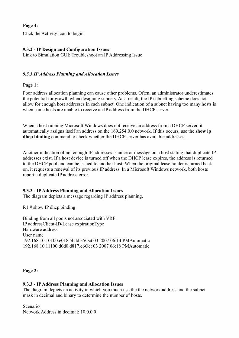
9.3.3 - IP Address Planning and Allocation IssuesThe diagram depicts a message regarding IP address planning.
R1 # show IP dhcp binding
Binding from all pools not associated with VRF: IP addressClient-ID/Lease expirationType Hardware address User name 192.168.10.10100.e018.5bdd.35Oct 03 2007 06:14 PMAutomatic 192.168.10.11100.d0d0.d817.e6Oct 03 2007 06:18 PMAutomatic
Page 2:
9.3.3 - IP Address Planning and Allocation IssuesThe diagram depicts an activity in which you much use the the network address and the subnet mask in decimal and binary to determine the number of hosts.
Scenario Network Address in decimal: 10.0.0.0

Subnet Mask in decimal: 255.255.254.0 Network address in binary: 00001010.00000000.00000000.00000000. Subnet Mask in binary: 11111111.11111111.11111110.10000000 What are the number of hosts?
Page 3:
Lab Activity
Create an IP addressing scheme that allows for 20% growth in the number of attached hosts.
Click the Lab icon to begin.
9.3.3 - IP Address Planning and Allocation IssuesLink to Hands-on Lab: Designing an IP Subnetting Scheme for Growth
9.3.4 DHCP and NAT Issues
Page 1:
DHCP can create another level of complication when troubleshooting network issues. If hosts are configured to use DHCP and are not able to connect to the network, verify that IP addressing is assigned using the Windows command, ipconfig /all. If hosts are not receiving IP addressing assignments, it is necessary to troubleshoot the DHCP configuration.
Regardless of whether the DHCP service is configured on a dedicated server or on the router, the first step in troubleshooting is to check the physical connectivity. If a separate server is used, check that the server is receiving network traffic. If the DHCP service is configured on a router, use the show interfaces command on the router to confirm that the interface is operational. If the interface connected to the host network is down, the port does not pass traffic, including DHCP requests.
Next, verify that the DHCP server is correctly configured and has available IP addresses to lease. After this is confirmed, check for any address conflicts. Address conflicts can occur even if there are available addresses within the DHCP pool. This can happen if a host is statically configured with an address that is also contained in the range of the DHCP pool.
Use the show ip dhcp conflict command to display all address conflicts recorded by the DHCP server. If an address conflict is detected, the address is removed from the pool and not assigned until an administrator resolves the conflict.
If none of these steps diagnoses the problem, test to ensure that the issue is actually with DHCP. Configure a host with a static IP address, subnet mask, and default gateway. If the workstation is

unable to reach network resources with a statically configured IP address, the root cause of the problem is not DHCP. At this point, network connectivity troubleshooting is required.
9.3.4 - DHCP and NAT IssuesThe diagram depicts a Windows cmd.exe window showing the ipconfig /all command.
Page 2:
DHCP is a broadcast protocol, which means that the DHCP server must be reachable through a broadcast message. Because routers normally do not forward broadcasts, either the DHCP server must be on the same local network as the hosts or the router must be configured to relay the broadcast messages.
A router can be configured to forward all broadcast packets, including DHCP requests, to a specific server using the ip helper-address command. This command allows a router to change the destination broadcast addresses within a packet to a specified unicast address:
Router(config-if)# ip helper-address x.x.x.x
Once this command is configured, all broadcast packets will be forwarded to the server IP address specified in the command, including DHCP requests.
When a router forwards address requests, it is acting as a DHCP relay agent. If DHCP relay is not operational, no hosts can obtain an IP address. When no hosts can obtain an IP address from a DHCP server that is located on another network, verify that the helper address is configured correctly on the router.
9.3.4 - DHCP and NAT IssuesThe diagram depicts examples of how DHCP relay operates.
DHCP Problem Router, R1, connects to a WAN via D C E. R1 also connects to network 192.168.10.0 /24 via F A 0 /0 with the link address 192.168.10.1/24 to the F A 0 /1 port of switch S1. S1 (192.168.10.2 /24) connects via F A 0 /2 to host, PC1, (192.168.10.10 /24). R1 also connects to network 192.168.11.0 /24 via F A 0 /1 to the F A 0 /1 port of switch S2 with the link address 192.168.11.1 /24. S2 (192.168.11.2 /24) connects via F A 0 /24 to DHCP server (192.168.11.5 /24).
PC1 says, "Looking for a DHCP server ..." R1 says, "Sorry, I can not forward any broadcasts outside of your network subnet ..."
Host Problem (PC1) C:\Documents and Settings\Administrator>ip config /release
Windows IP Configuration

Ethernet adapter Local Area
Connection: Connection-specific DNS Suffix . : IP address. . . . . . . . . . . . : 0.0.0.0 Subnet mask . . . . . . . . . . . : 0.0.0.0 Default gateway . . . . . . . . . :
C:\Documents and Settings\Administrator>ip config /renew
Windows IP Configuration
An error occurred while renewing interface Local Area Connection : unable to contact your DHCP server. Request has timed out.
C:\Documents and Settings\Administrator>
Relay Config Router, R1, connects to a WAN via D C E. R1 also connects to network 192.168.10.0/24 via F A 0 /0 with the link address 192.168.10.1 /24 to the F A 0 /1 port switch of S1. S1 (192.168.10.2/24) connects via F A 0 /2 to host, PC1, (192.168.10.10/ 24). R1 also connects to network 192.168.11.0/24 via F A 0 /1 to the F A 0 /1 port of switch, S2, with the link address 192.168.11.1/24. S2 (192.168.11.2 /24) connects via F A 0 /24 to DHCP server (192.168.11.5 /24).
R1 # config t R1 (config) # interface F A 0 /0 R1 (config-if) # IP helper-address 192.168.11.5 R1 (config) # end
Host Renew C:\Documents and Settings\Administrator>ip config /release
Windows IP Configuration
Ethernet adapter Local Area
Connection: Connection-specific DNS Suffix . :
IP Address. . . . . . . . . . . . : 0.0.0.0 Subnet Mask . . . . . . . . . . . : 0.0.0.0 Default Gateway . . . . . . . . . :
C:\Documents and Settings\Administrator>ip config /renew
Windows IP Configuration
Ethernet adapter Local Area Connection:
Connection-specific DNS Suffix . : IP address. . . . . . . . . . . . : 192.168.10.11 Subnet Mask . . . . . . . . . . . : 255.255.255.0 Default Gateway . . . . . . . . . : 192.168.10.1

C:\Documents and Settings\Administrator>
Page 3:
If the hosts on the internal network are assigned private addresses, NAT is required to communicate with the public network. Usually the first indication that there is a NAT problem is that users cannot reach sites located on the Internet. There are three types of address translation: static, dynamic, and PAT. Two common types of configuration errors affect all three translation methods.
Incorrect Designation of Inside and Outside Interfaces
It is critical that the correct interfaces are designated as the inside or outside interface for NAT. In most NAT implementations, the inside interface connects to the local network, which uses private IP address space. The outside interface connects to the public network, usually the ISP. Verify this configuration using the show running-config interfacecommand.
Incorrect Assignment of Interface IP Address or Pool Addresses
In most NAT implementations, the IP address pool and static NAT translation entries must use IP addresses that are on the same local IP network as the outside interface. If not, addresses are translated, but no route to the translated addresses are found. Check the configuration to verify that all the translated addresses are reachable. When the address translation is configured to use the outside interface address in PAT, make sure that the interface address is on the correct network and is configured with the proper subnet mask.
Another common issue is that when dynamic NAT or PAT is enabled, external users are no longer able to connect to internal devices. If external users must be able to reach specific servers on the internal network, be sure that static translations are configured.
9.3.4 - DHCP and NAT IssuesThe diagram depicts dynamic NAT configuration commands.
access-list 1 permit 192.168.0.0 0.0.255.255 !-Defines which addresses are eligible to be translated ip nat pool NAT-POOL2 209.165.200.226 209.165.200.240 !-Defines a pool of addresses named NAT-POOL2 to be used in NAT translation ip nat inside source list 1 pool NAT-POOL2 overload !-Binds the NAT pool with ACL1 interface serial 0/0/0 ip nat inside !-Identifies interface Serial 0/0/0 as an inside NAT interface interface serial 0/1/0 ip nat outside !-Identifies interface Serial 0/1/0 as an outside NAT interface

Page 4:
If you are certain that NAT is configured correctly, it is important to verify that NAT is operational.
One of the most useful commands when verifying NAT operation is the show ip nat translations command. After viewing the existing translations, clear them using the clear ip nat translation * command. Be aware that clearing all IP translations on a router may disrupt user services. Then use the show ip nat translations command again. If new translations appear, there may be another problem causing the loss of Internet connectivity.
Verify that there is a route to the Internet for the translated addresses. Use traceroute to determine the path the translated packets are taking and verify that the route is correct. Also, if possible, trace the route to a translated address from a remote device on the outside network. This can help isolate the next troubleshooting target. There may be a routing problem on the router where the trace output stops.
9.3.4 - DHCP and NAT IssuesThe diagram depicts NAT configurations and output.
A LAN with two PCs, 192.168.10.10 and 192.168.10.11, are connected to a switch which is also connected to router, R2, using its F A 0 /0 with IP address 192.168.10.1. Serial 0/1/0 of R2 is connected to the Internet cloud with an IP address of 209.165.200.225.
NAT Overload access-list 1 permit 192.168.10.0 0.0.0.0.255 ip nat inside source list 1 interface serial 0/1/0 overload interface fastethernet0/0 ip nat inside interface serial 0/1/0 ip nat outside
NAT Translations R2 # show IP nat translations ProInside globalInside localOutside local tcp209.165.200.225:16642192.168.10.10:16642209.165.200.254:80 tcp209.165.200.225:62452192.168.10.11:62452209.165.200.254:80 Outside global 209.165.200.254:80 209.165.200.254:80
R2 # show IP nat translations verbose Pro Inside global Inside local Outside local Outside global tcp 209.165.200.225:16642 192.168.10.10:16642 209.165.200.254:80 209.165.200.254:80 create 00:01:45, use 00:01:43 timeout :86400000, left 23:58:16, Map-Id (In) :1, flags: extended, use count: 0, entry- id: 4, 1c_entries : 0 tcp 209.165.200.225:62452 192.168.10.11:62 452 209.165.200.254:80 209.165.200 .254:80 create 00:00:37, use 00:00:35 timeout:86400000, left 23:59:24, Map-Id (In): 1,

flags: extended, use count : 0, entry-id : 5, lc_entries: 0 R2 #
Cleared NAT R2 # clear IP nat translation * R2 # show IP nat translations
R2 #
Page 5:
Packet Tracer Activity
Use show commands to troubleshoot DHCP and NAT.
Click the Packet Tracer icon to begin.
9.3.4 - DHCP and NAT IssuesLink to Packet Tracer Exploration: Troubleshooting DHCP and NAT
9.3.5 Certification Study Guide
Page 1:
CCENT Study Guide
Click the lab icon to download a CCENT Preparation Guide for section 9.3.
Click the lab icon to download a CCENT Preparation Guide.
9.3.5 - Certification Study GuideLink to Hands-on-Lab: CCENT Study Guide 3
9.4 Troubleshooting Layer 3 Routing Issues
9.4.1 Layer 3 Routing Issues
Page 1:
Layer 3 encompasses the addressing of networks and hosts, and the protocols that route packets between networks.

Most networks have a number of different types of routes, including a combination of static, dynamic, and default routes. Problems with routing can cause network failures or adversely affect network performance. These problems can be the result of manual route entry errors, routing protocol configuration and operation errors, or failures at lower layers of the OSI model.
To troubleshoot Layer 3 problems, it is important to understand how routing works, including how each type of route functions and is configured.
You may want to review the materials and activities in CCNA Discovery: Networking for Home and Small Businesses and CCNA Discovery: Working at a Small-to-Medium Business or ISP on routing and routing protocols before continuing with this chapter.
9.4.1 - Layer 3 Routing IssuesThe diagram depicts symptoms for issues on Layer 3, the Network Layer.
Layer 3: Network routing issues. Symptoms. Network failure. Network performance below baseline.
Page 2:
The status of a network can change frequently for a variety of reasons, including:
• An interface fails. • A service provider drops a connection.• The available bandwidth is overloaded.• An administrator enters an incorrect configuration.
When there is a change in the network status, routes can be lost, or an incorrect route can be installed into the routing table.
The primary tool to use when troubleshooting Layer 3 routing problems is the show ip route command. This command displays all the routes the router uses to forward traffic. The routing table consists of route entries from the following sources:
• Directly connected networks• Static routes• Dynamic routing protocols
Routing protocols choose which routes are preferred based on route metrics. Directly connected networks have a metric of 0, static routes also have a default metric of 0, and dynamic routes have various routing metrics, depending on the routing protocol used.

If there is more than one route to a specific destination network, the route with the lowest administrative distance (AD) is installed into the routing table.
Any time a routing problem is suspected, use the show ip route command to ensure that all the expected routes are installed in the routing table.
9.4.1 - Layer 3 Routing IssuesThe diagram depicts a table with administrative distance and default metric information about various route sources.
Route Source: Connected Administrative Distance: 0 Default Metric(s): 0
Route Source: Static Administrative Distance: 1 Default Metric(s): 0
Route Source: EIGRP Summary Route Administrative Distance: 5 Default Metric(s): N/A
Route Source: External BGP Administrative Distance: 20 Default Metric(s): Value assigned by Admin
Route Source: Internal EIGRP Administrative Distance: 90 Default Metric(s): Bandwidth Delay
Route Source: IGRP Administrative Distance:100 Default Metric(s): Bandwidth, Delay
Route Source: OSPF Administrative Distance: 110 Default Metric(s): Link cost (bandwidth)
Route Source: IS-IS Administrative Distance: 115 Default Metric(s): Link cost (Value assigned by admin)
Route Source: RIP Administrative Distance: 120 Default Metric(s): Hop count
Route Source: External EIGRP Administrative Distance: 170 Default Metric(s): N/A

Route Source: Internal BGP Administrative Distance: 200 Default Metric(s): Value assigned by Admin
Page 3:
Connected Route Problems
Directly connected routes are automatically installed in the routing table when an IP address is configured on an interface, and the interface is enabled using the no shutdown command. If a directly connected route does not appear in the table, use the show interfaces or show ip interface brief command to verify that an address is assigned and that the interface is in an up/up state.
Static and Default Route Problems
When a static or default route does not appear in the routing table, the problem is most likely a configuration error. Static and default routes must use either an exit interface or the IP address of a next hop router. Static routing errors sometimes occur because the next hop address is not in the correct IP address range of any directly connected network. Verify that the configuration statements are correct and that the exit interfaces used by the routes are in an up/up state.
Dynamic Route Problems
There are many different types of problems that can cause dynamic routes to not appear in the routing table. Because dynamic routing protocols exchange route tables with all other routers in the network, a missing route could be caused by a misconfiguration on one or more of the routers on the path to the destination.
9.4.1 - Layer 3 Routing IssuesThe diagram depicts an Edit Router C Window with the focus on the following information.
R - RIP
Directly Connected Route C 172.16.0.0 /16 is directly connected, Fast Ethernet 0 10.0.0.0 /24 is subnetted, 1 subnets
Static Route S 10.10.10.0 [1 /0] via 192.168.1.2
Dynamically Updated Route R 192.168.2.0 / 24 [120 /1] via 192.168.1.2, 00:00:23
Default Route

S* 0.0.0.0 /0 [1 /0] via 192.168.1.2 Gateway of last resort is 192.168.1.2 to network 0.0.0.0
Page 4:
Packet Tracer Activity
Use routing table principles to solve a routing problem.
Click the Packet Tracer icon to begin.
9.4.1 - Layer 3 Routing IssuesLink to Packet Tracer Exploration: Applying Routing Table Principles
9.4.2 Dynamic Routing Errors
Page 1:
Routing table updates usually occur when a new network is configured or an already configured network becomes unreachable.
If directly connected routes appear in the router table, the routing table is accessed and changed only if the directly connected interface changes states. If static or default routes are configured, the routing table changes only if new routes are specified or if the exit interface specified in the static or default route changes states.
Dynamic routing protocols automatically send updates to other routers in the network. If dynamic routing is enabled, a router accesses and changes its own routing table any time a change is reported in an update from a neighboring router.
RIP is a dynamic routing protocol used in small- to medium-sized LANs. When troubleshooting issues specific to RIP, check the versioning and configuration statements.
It is always best to use the same version of the routing protocol on all routers. Although RIPv1 and RIPv2 are compatible, RIPv1 does not support classless routing or variable length subnet masks (VLSM). This can create issues if both RIPv1 and RIPv2 are configured to run on the same network. Additionally, while RIPv2 automatically listens for both RIPv1 and RIPv2 updates from neighbors, RIPv1 does not listen for RIPv2 updates.
Routing problems also occur if there are incorrect or missing network statements. The network statement does two things:
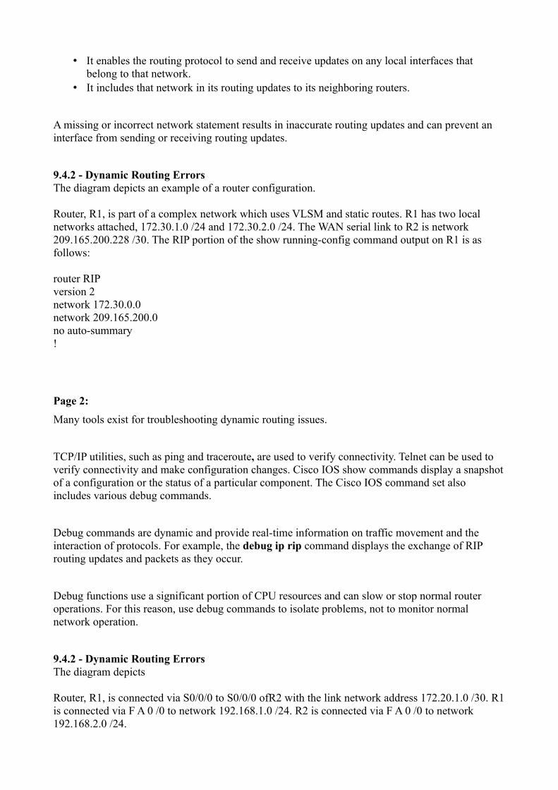
• It enables the routing protocol to send and receive updates on any local interfaces that belong to that network.
• It includes that network in its routing updates to its neighboring routers.
A missing or incorrect network statement results in inaccurate routing updates and can prevent an interface from sending or receiving routing updates.
9.4.2 - Dynamic Routing ErrorsThe diagram depicts an example of a router configuration.
Router, R1, is part of a complex network which uses VLSM and static routes. R1 has two local networks attached, 172.30.1.0 /24 and 172.30.2.0 /24. The WAN serial link to R2 is network 209.165.200.228 /30. The RIP portion of the show running-config command output on R1 is as follows:
router RIP version 2 network 172.30.0.0 network 209.165.200.0 no auto-summary !
Page 2:
Many tools exist for troubleshooting dynamic routing issues.
TCP/IP utilities, such as ping and traceroute, are used to verify connectivity. Telnet can be used to verify connectivity and make configuration changes. Cisco IOS show commands display a snapshot of a configuration or the status of a particular component. The Cisco IOS command set also includes various debug commands.
Debug commands are dynamic and provide real-time information on traffic movement and the interaction of protocols. For example, the debug ip rip command displays the exchange of RIP routing updates and packets as they occur.
Debug functions use a significant portion of CPU resources and can slow or stop normal router operations. For this reason, use debug commands to isolate problems, not to monitor normal network operation.
9.4.2 - Dynamic Routing ErrorsThe diagram depicts
Router, R1, is connected via S0/0/0 to S0/0/0 ofR2 with the link network address 172.20.1.0 /30. R1 is connected via F A 0 /0 to network 192.168.1.0 /24. R2 is connected via F A 0 /0 to network 192.168.2.0 /24.

RIP-related command output for R1 is as follows:
Command 1: show IP protocols Default version control: send version 2, receive version 2
Routing for Networks: 172.20.0.0 192.168.1.0
Command 2: show running-config interface FastEthernet0/0 description LAN gateway for 192.168.1.0 IP address 192.168.1.1 255.255.255.0 duplex auto
interface Serial0/0/0 IP address 172.20.1.1 255.255.255.252 no fair-queue ! Router rip version 2 passive-interface FastEthernet0/0 network 172.20.0.0 network 192.168.1.0 ! Banner m o td # Unauthorized use prohibited # !
Command 3: show interfaces MTU 1500 bytes, BW 100000 Kbit, D L Y 100 u sec,
Auto-duplex, Auto speed, 100BaseTX/FX
Command 4: show IP interface FastEthernet0/0 Multicast reserved groups joined: 224.0.0.9 Serial0/0/0 Multicast reserved groups joined: 224.0.0.9
Command 5: show IP route R192.168.2.0 [120/1] via 172.20.1.2, 00:00:04, Serial0/0/0
Command 6: debug IP rip * Sep 12 21:09:16.399:RIP: received v2 update from 172.20.1.2 on Serial0/0/0
Page 3:
Packet Tracer Activity
Subnet an address space, configure devices, and use combination of RIPv2 and static routing to

provide connectivity between remote hosts.
Click the Packet Tracer icon to begin.
9.4.2 - Dynamic Routing ErrorsLink to Packet Tracer Exploration: Configuring RIPv2 (Challenge)
Page 4:
Lab Activity
Troubleshoot a RIP router network configured with errors.
Click the Lab icon to begin.
9.4.2 - Dynamic Routing ErrorsLink to Hands-on Lab: Correcting RIPv2 Routing Problems
9.4.3 Certification Study Guide
Page 1:
CCENT Study Guide
Click the lab icon to download a CCENT Preparation Guide for section 9.4.
Click the lab icon to download a CCENT Preparation Guide.
9.4.3 - Certification Study GuideLink to Hands-on Lab: CCENT Study Guide 4
Download the CCENT Study Guide for Section 9.4.
9.5 Troubleshooting Layer 4 and Upper Layer Issues
9.5.1 Layer 4 Traffic Filtering Errors
Page 1:
Layer 4, the Transport Layer, is considered a transition between the upper and lower layers of the OSI model. Layer 4 is responsible for transporting data packets and specifies the port number used to reach specific applications. Layer 4 network problems can arise at the edge of the network where

security technologies are examining and modifying the traffic. Many problems are caused by firewalls that are configured to deny traffic based on port numbers, even though this traffic should be forwarded.
Layer 4 supports both UDP and TCP traffic. Some applications use TCP, some use UDP, and some use both. When denying traffic based on the port number, it is necessary to specify the transport protocol used. Some engineers are unsure of which transport protocol is used by specific applications and therefore deny the port number for both TCP and UDP traffic. This practice may unexpectedly deny traffic that should be allowed.
Firewalls are also often configured to deny everything except the applications specified in the permit statements. If traffic that should be permitted is not included in the firewall statements, or if a new application is added to the network without a corresponding permission being added to the firewall, filtering problems occur.
A common indication of Layer 4 problems is users reporting that some web services, especially video or audio, are not reachable.
Verify that the ports being permitted and denied by the firewall are the correct ones for the applications. For a better understanding of which ports correspond to specific applications, review the information on TCP, UDP, and ports in CCNA Discovery: Networking for Home and Small Businesses and CCNA Discovery: Working at a Small-to-Medium Business or ISP.
9.5.1 - Layer 4 Traffic Filtering ErrorsThe diagram depicts symptoms for issues on Layer 4, the Transport Layer. The table describes the abbreviation and definition for well-known ports.
Layer 4: Transport Layer Problems. Symptoms. Intermittent network problems Security problems Trouble reaching some web sites or other network-based applications and services.
Well-known Ports
Destination port number: 20 Abbreviation: FTP Data Definition: File Transfer Protocol (for data transfer)
Destination port number: 21 Abbreviation: FTP Control Definition: File Transfer Protocol (to establish connection)
Destination port number: 23 Abbreviation: TELNET Definition: TELetype NETwork
Destination port number: 25

Abbreviation: SMTP Definition: Simple Mail Transfer Protocol
Destination port number: 53 Abbreviation: DNS Definition: Domain Name Service
Destination port number: 67 Abbreviation: DHCP v4 Client Definition: Dynamic Host Configuration Protocol (Client)
Destination port number: 68 Abbreviation: DHCP v4 Server Definition: Dynamic Host Configuration Protocol (Server)
Destination port number: 69 Abbreviation: TFTP Definition: Trivial File Transfer Protocol
Destination port number: 80 Abbreviation: HTTP Definition: Hypertext Transfer Protocol
Destination port number: 110 Abbreviation: POP3 Definition: Post Office Protocol (version 3)
Destination port number: 137 Abbreviation: NBNS Definition: Microsoft NetBIOS Name Service
Destination port number: 143 Abbreviation: I MAP4 Definition: Internet Message Access Protocol (version 4)
Destination port number: 161 Abbreviation: SNMP Definition: Simple Network Management Protocol
Destination port number: 443 Abbreviation: HTTPS Definition: Hypertext Transfer Protocol Secure
Page 2:
9.5.1 - Layer 4 Traffic Filtering ErrorsThe diagram depicts an activity in which you must match the protocol name to the port number.
Port Numbers

A. 21 B. 53 C. 161 D. 67 E. 110 F. 23 G. 80 H. 25 I. 143
Protocol Names One. FTP Two. Telnet Three. SMTP Four. HTTP Five. POP3 Six. I MAP4 Seven. DNS Eight. DHCP Nine. SNMP
9.5.2 Troubleshooting Upper Layer Problems
Page 1:
Most of the upper layer protocols provide user services that are typically used for network management, file transfer, distributed file services, terminal emulation, and email. Protocols at these layers are often referred to as TCP/IP Application Layer protocols, because the TCP/IP model Application Layer encompasses the upper three layers of the OSI model.
The most widely known and implemented TCP/IP Application Layer protocols include:
• Telnet - Enables users to establish terminal session connections with remote hosts.• HTTP - Supports the exchange of text, graphic images, sound, video, and other multimedia
files on the web.• FTP - Performs interactive file transfers between hosts, using TCP.• TFTP - Performs basic interactive file transfers typically between hosts and networking
devices, using UDP .• SMTP - Supports basic email message delivery services.• POP3 - Connects to mail servers and downloads email to a client application.• IMAP4 - Enables email clients to retrieve messages and store email on servers.• SNMP - Collects information from managed devices.• NTP - Provides updated time to hosts and network devices.• DNS - Maps IP addresses to the names assigned to hosts.• SSL - Provides encryption and security for HTTP transactions.• SSH - Provides secure remote terminal access to servers and networking devices.

9.5.2 - Troubleshooting Upper Layer ProblemsThe diagram depicts protocols used on the upper layers of the O S I Model: Layer 5, the Session Layer, Layer 6, the Presentation Layer, and Layer 7, the Application Layer. The upper layers of the O S I model are referred to as the TCP/IP Application Layer protocols.
TCP/IP Application Layer protocols. HTTP. Telnet. FTP. TFTP. SMTP. POP3. I MAP4. SNMP. NTP. DNS. SSL. SSH.
Page 2:
It can be difficult to isolate problems to the upper layers, especially if the client configuration does not reveal any obvious problems. To determine that a network problem is with an upper layer function, start by eliminating basic connectivity as the source of the problem.
Using the "divide and conquer" method of troubleshooting, begin with verifying Layer 3 connectivity.
Step 1. Ping the host default gateway.
Step 2. Verify end-to-end connectivity.
Step 3. Verify the routing configuration.
Step 4. Ensure that NAT is working correctly.
Step 5. Check for firewall filter rules.
If the problem exists on a remote network, end-to-end connectivity cannot be verified because there is no control over all the connections. For this reason, it is possible that even though the configurations on the local devices are correct, there is still a problem with the remote network. Be sure to check with the ISP to ensure that their network connection is up and operational.
If all these steps are completed successfully, and it is verified that the end-to-end connectivity is not

the issue, but the end device is still not operating as expected, the problem has been isolated to the upper layers.
9.5.2 - Troubleshooting Upper Layer ProblemsThe diagram depicts the process for troubleshooting the upper layers.
Step 1. Ping the host default gateway. If both the host and the server can successfully ping their default gateways, Layer 1 and Layer 2 services are functioning properly and Layer 3 local network connectivity exists. If the ping to the local default gateway address fails, troubleshoot Layers 3, 2, and 1 to locate the source of the problem. Step 2. Verify end-to-end connectivity. Ping or telnet from the host to a remote server or networking device. If successful, Layer 3 routing is operating correctly. When Layers 1, 2, and 3 are functioning properly, the issue must exist at a higher layer. If this ping is unsuccessful, it is necessary to troubleshoot the routing, NAT and firewall configurations to ensure proper packet delivery. Step 3. Verify the routing configuration. Ensure that the routing configuration is correct and that routes are updating as expected. If the routing table does not contain expected routes, troubleshoot and fix the routing configuration and attempt Step 2 again. If still unable to ping, check the NAT configuration. Step 4. Ensure that NAT is working correctly. When there is a problem reaching services on a remote network, such as over the Internet, NAT may not be functioning correctly. Use the show IP nat translations command to verify that translations are occurring. Clear the NAT translations with the clear IP nat translation * command and try to access the external resource again. If still not successful, check the configuration of the inside and outside interfaces. When the NAT configuration has been verified, attempt Step 2 again. If still unable to ping, check for firewall filter rules. Step 5. Check for firewall filter rules. Even though there is IP connectivity between a source and a destination, problems may still exist for a specific upper layer protocol, such as FTP, HTTP, or Telnet. These protocols ride on top of the basic IP transport but are subject to protocol-specific problems relating to packet filters and firewalls. Verify that the necessary ports are permitted on all firewalls.
Page 3:
Upper layer problems prevent services from being provided to application programs. A problem at the upper layers can result in unreachable or unusable resources, even when the lower layers are functional. It is possible to have full network connectivity, but the application cannot provide data.
Problems with upper layer functions usually affect just a few applications, perhaps even only one. It is not unusual for a help desk technician to get a call from a user who cannot receive email, although all other applications are functioning correctly.
Misconfigured client applications account for the majority of upper layer network problems. When an incorrect email or FTP server is specified, the client cannot find and retrieve information. When more than one application is affected, the upper layer problem may be attributed to a DNS server issue.

To verify that DNS is functioning correctly and can resolve server addresses, use the Windows command nslookup. If DNS is not working as expected, ensure that the correct DNS server address is configured on the host. When hosts receive DNS server information from a DHCP server, verify that the DHCP server has the correct IP address for the DNS server.
If the DNS server is operational and reachable, check for DNS zone configuration errors. Look for a typographical error in an address or name within the files.
9.5.2 - Troubleshooting Upper Layer ProblemsThe diagram depicts symptoms for issues for the upper layers of the O S I Model: Layer 7, Application, Layer 6, Presentation, and Layer 5, Session.
Upper Layer Problems. Symptoms: User complains about slow application performance Application error message Unable to access application services, such as FTP Unable to access Web services
Page 4:
The upper layers are responsible for encryption and compression. A mismatch between the way a client encrypts or compresses the data and the way the server interprets it can cause applications to not function or to function poorly.
When a problem occurs on a single host or workstation, it may be a problem with the way the information is being interpreted in the host software. Browser plug-in programs, such as Adobe Reader, often perform upper layer functions. These programs must be kept updated for web pages to display correctly.
Using an incorrect protocol to request data can cause a web page to be unreachable. For example, it may be necessary to specify https:// on the browser address line, rather than http:// to retrieve an SSL-protected web page.
9.5.2 - Troubleshooting Upper Layer ProblemsThe diagram depicts a Firefox browser window with a "Server not found" error message.
9.5.3 Using Telnet to Check Upper Layer Connectivity
Page 1:
Telnet is an excellent tool to use when troubleshooting problems with upper layer functions. Using Telnet to access the networking devices enables the technician to enter commands on each device as

if they were locally attached. In addition, the ability to reach devices using Telnet indicates that the lower layer connectivity exists between the devices.
However, Telnet is an insecure protocol, which means that all data communicated can be captured and read. If there is a possibility that communications can be intercepted by unauthorized users, Secure Shell (SSH) protocol should be used instead. SSH is a more secure method for remote device access.
Most newer versions of the Cisco IOS software contain an SSH server. In some devices, this service is enabled by default. Other devices require the SSH server to be manually enabled.
Cisco IOS devices also include an SSH client that can be used to establish SSH sessions with other devices. Similarly, a remote computer with an SSH client can be used to start a secure CLI session. SSH client software is not provided by default on all computer operating systems. The technician may need to acquire, install, and configure SSH client software on the computer.
Review the material in CCNA Discovery: Working at a Small-to-Medium Business or ISP on configuring and using SSH.
9.5.3 - Using Telnet to Check Upper Layer ConnectivityThe diagram depicts an example of using Telnet to check an upper level connection.
A Telnet client with a virtual terminal application window is connected via the internet to a Telnet server. Telnet provides a way to use a computer, connected via the network, to access a network device as if the keyboard and monitor were directly connected to the device.
Page 2:
Lab Activity
Access networking devices using Telnet and SSH.
Click the Lab icon to begin.
9.5.3 - Using Telnet to Check Upper Layer ConnectivityLink to Hands-on Lab: Using Telnet and SSH to Access Networking Devices
9.5.4 Certification Study Guide
Page 1:
CCENT Study Guide

Click the lab icon to download a CCENT Preparation Guide for section 9.5.
Click the lab icon to download a CCENT Preparation Guide.
9.5.4 - Certification Study GuideLink to Hands-on Lab: CCENT Study Guide 5
Download the CCENT Study Guide for Section 9.5.
9.6 Preparing for Cisco Certification
9.6.1 Knowledge, Skills and Abilities
Page 1:
The Cisco Certified Entry Networking Technician (CCENT) certification validates the skills required for entry-level network support positions, the starting point for many successful careers in networking. CCENT certification is the first step toward achieving CCNA certification (Cisco Certified Network Associate), which covers medium-size enterprise branch networks that have more complex connections. To obtain CCENT certification, a candidate must pass the ICND1 examination at a Cisco Certified Testing Center.
The ICND1 exam (640-822) tests the ability to install, operate, and troubleshoot a small branch office network. The exam includes topics on networking fundamentals:
• Connecting to a WAN• Basic security and wireless concepts• Routing and switching • TCP/IP and OSI models• IP addressing• WAN technologies• Operating and configuring Cisco IOS devices• Configuring RIPv2, static and default routing• Implementing NAT and DHCP• Configuring simple networks
Mastering a Cisco certification exam is not an easy task. Cisco has maintained the difficulty of the CCNA exam series by changing the exam requirements regularly. Some candidates pass the exam the first time; many pass it after multiple attempts, while some do not pass it. Good preparation is the best way to ensure that you pass the exam the first time.
9.6.1 - Knowledge, Skills, and AbilitiesThe diagram depicts the steps to take to become CCENT and CCNA certified.

Option 1 - CCENT/CCNA Certification Take and pass: ICND1 640-822 Exam, CCNA Discovery: Networking for Home and Small Businesses, CCNA Discovery: Working at a Small-to-Medium Business or ISP, to become CCENT Certified.
Then take and pass: ICND2 640-816 Exam, CCNA Discovery: Introducing Routing and Switching in the Enterprise, CCNA Discovery: Designing and Supporting Computer Networks, to become CCNA Certified.
Option 2 - CCNA Certification Take and pass the CCNA 640-802 Exam, CCNA Discovery: Networking for Home and Small Businesses, CCNA Discovery: Working at a Small-to-Medium Business or ISP, CCNA Discovery: Introducing Routing and Switching in the Enterprise, CCNA Discovery: Designing and Supporting Computer Networks, to become CCNA Certified.
Page 2:
Before preparing for any certification examination, it is important to understand the purpose of the exam. Cisco certification examinations are designed to measure the knowledge, skills, and abilities of an individual in a defined area of expertise. The exams use a combination of techniques to enable a candidate to demonstrate readiness to perform various networking tasks. The exam can contain multiple choice questions, various exercises, and simulated network configuration tasks. Each question or task is designed to address a specific objective. The Cisco certification website lists the objectives for the ICND1 exam.
Cisco certification website
9.6.1 - Knowledge, Skills, and AbilitiesThe diagram depicts a brief description of the knowledge, skills, and abilities that are required to pass the certification exams.
Knowledge Knowledge statements are typically factual or procedural in nature. They are related directly to the performance of a function.
Skills Skill statements refer to the capability to manually, verbally, or mentally manipulate data or things to achieve a desired result. Skills can be measured by a performance test where quantity and quality of performance are tested, usually within an established time limit. Examples of skill related tasks include skill in typing or skill in operating a vehicle.
Abilities

Ability statements refer to the power to perform an observable activity at the present time. This means that abilities have been proven through activities or behaviors that are similar to those required on the job. An example is the ability to plan and organize work.
9.6.2 Networking Knowledge, Skills and Abilities
Page 1:
To perform most networking tasks, some knowledge must be recalled from memory. This type of knowledge is made up of facts. When studying for a certification exam, identify the pertinent facts associated with each exam objective. Some individuals find it useful to create flashcards to help memorize these facts. While there may be a few questions on the exam that require the basic factual answers, more often the factual knowledge is needed to diagnose or solve a networking problem.
9.6.2 - Networking Knowledge, Skills, and AbilitiesThe diagram depicts examples of the type of questions used to test knowledge.
In a RIP network, what is the maximum number of hops a packet can take before a destination becomes unreachable? Which routing protocols use a distance vector algorithm? How does a switch determine which port to use to reach a destination? Where is the startup configuration stored on a Cisco router?
Page 2:
Many skills are required when performing networking tasks. Some skills are fairly easy, such as creating and terminating a crossover cable. Other skills are more difficult, such as mastering IP subnetting.
The mastery of networking skills requires practice. Lab and Packet Tracer activities are designed to provide a structured practice environment for learners.
Cisco certifications measure and validate the networking skills of an individual based on how they interact with Cisco networking devices. Because of this, it is very important to practice with Cisco IOS software. Many exam tasks require the interpretation of Cisco IOS command output, especially the output of the various show commands.
9.6.2 - Networking Knowledge, Skills, and AbilitiesThe diagram depicts a sample question that is designed to test the IP addressing skills of the candidate. It also requires the candidate to be familiar with configuring Cisco I O S software.
Sample Question: Refer to the exhibit below. Which Cisco I O S command will assign the first usable IP address in the subnetwork to FastEthernet0/1 of R T A?

Exhibit: The host, PC-A, (IP 172.18.16.230/22) is connected to a switch which is connected to the router F A 0 /1 interface. S0/1 of the router is connected to the Internet cloud.
Command One.R T A (config-if) # ip address 172.18.13.1 255.255.254.0. Command Two.R T A (config-if) # ip address 172.18.14.1 255.255.252.0. Command Three.R T A (config-if) # ip address 172.18.14.1 255.255.255.252. Command Four.R T A (config-if) # ip address 172.18.16.1 255.255.252.0. Command Five.R T A (config-if) # ip address 172.18.16.1 255.255.252.252. Command Six.R T A (config-if) # ip address 172.18.16.229 255.255.255.252.
Page 3:
The ability to plan, organize, execute, and problem solve is critical to the success of an entry-level network technician. In a certification exam environment, these abilities are usually measured using configuration and troubleshooting tasks. Effort is made when designing the exams to simulate conditions that an individual would find when performing an actual networking job. These conditions can be presented on the exam using scenarios or simulations.
Preparing for a scenario-based or simulation task is not as simple as memorizing a fact or practicing a specific skill. These types of tasks require an individual to apply both the facts and skills to solve a problem or meet a stated requirement.
One of the best ways to develop troubleshooting abilities is to start by analyzing what knowledge and skills are needed in order to perform specific networking tasks. When the necessary information is identified, anticipate what would happen if that information was not known. Make a list of the possible outcomes and determine what skills could be used to identify and correct any problems that may be created. That sounds difficult, but here are a few examples to consider:
• What would happen if a network technician did not know the correct number of host addresses available using a specific subnet mask? How could the problems be identified and corrected?
• What problems might arise in a RIPv2 network that has more than 15 hops from a source to a destination address? What would be a symptom of this problem? How could the problem be corrected?
9.6.2 - Networking Knowledge, Skills, and AbilitiesThe diagram depicts areas of analysis that should be considered when studying the RIP routing protocol: the information needed, possible outcomes, and possible symptoms of problems.
Task: Configure RIPv2 to route network traffic
Information needed Steps to configure RIPv2 routing. One.Log into the router. Two.Enter privileged mode. Three.Enter configuration mode.

Four.Enable RIP. Five.Enable version 2. Six.Configure a network statement for each connected network that participates in RIP. Cisco I O S commands to enable RIPv2 routing. One.Config t. Two.Router rip. Three.Version 2. Four.Network [address]. Five.Copy running-config startup-config. Network addresses for each connected network. Methods to verify if RIPv2 is configured correctly and working. One.Use show running-configuration command. Two.Use show IP route command. Three.Ping from a host to a remote IP address on another network. Four.Trace the route through the router to a remote IP address. Five.Use debug to verify the RIPv2 routing updates are being sent and received.
Possible incorrect outcomes if I do no posses the necessary knowledge I cannot enter configuration mode to being the configuration I forgot to configure version 2 or add the network statement I do not configure all the networks I enter the wrong IP address information I cannot verify if RIPv2 is operating correctly
Possible symptoms of problems Cannot ping hosts on other networks Cannot trace route through the router No routes appear in routing table of router
Page 4:
9.6.2 - Networking Knowledge, Skills, and AbilitiesThe diagram depicts an activity in which you must determine if each of the following tasks belongs in the knowledge, skills, or ability category.
Tasks. One.Troubleshoot a non-functioning network. Two.Calculate an IP subnet. Three.Configure an IP address on a router interface. Four.Plan the implementation of a new router. Five.List two distance vector routing protocols. Six.Build a Category 5 crossover cable. Seven.Design an IP address scheme. Eight.Explain the meaning of the term NAT.
Page 5:
Lab Activity

Identify the knowledge, skills, and abilities needed to perform the lab tasks.
Click the Lab icon to begin.
9.6.2 - Networking Knowledge, Skills, and AbilitiesLink to Hands-on Lab: Identifying Necessary Knowledge, Skills, and Abilities
9.6.3 Making the Commitment
Page 1:
Getting ready to take a certification exam can be an overwhelming task. There is much information to review, many skills to practice, and pressure to succeed. Just like installing a network for a customer, exam preparation is more successful if it is broken down into a series of smaller steps:
1. Making the commitment.
2. Creating a plan.
3. Practicing test taking.
After you complete these steps, you are ready to begin the exam preparation.
9.6.3 - Making the CommitmentThe diagram depicts an image of the certification pyramid offered by Cisco, from bottom to top, as follows:
CCENT CCNA CCNP CCIE
Page 2:
The first step to obtaining a Cisco certification is making the commitment to devote the time and effort necessary to prepare for the examination. This commitment needs to be assigned a top priority, because it will take time that was previously used for other activities.
In addition to taking time, preparing for a certification exam requires concentration. Find a place at home or at school where you can study for long periods of time uninterrupted. Trying to learn and

practice networking skills can be extremely difficult if other distractions are present.
Having the right equipment and resources is also important. Make sure that you have access to a computer, the on-line course materials, and Packet Tracer software. Discuss with your instructor how to schedule lab time to practice your skills on actual equipment. Find out if remote lab access over the Internet is available in your area.
Inform friends and family of your commitment to obtaining the CCENT certification. Explain to them that their assistance and support are needed during the exam preparation. Even if they have no understanding of networking, they can help you study with flashcards or ask practice questions. At a minimum, they can help by respecting your need for uninterrupted study time. If others in your class are preparing for the exam at the same time, it may be helpful to organize a study group.
9.6.3 - Making the CommitmentThis image depicts two students studying.
9.6.4 Creating a Plan
Page 1:
After you have made the commitment to dedicate the time necessary to prepare to take the ICND1 examination, the next step is creating a plan. A certification preparation plan includes information on how you intend to prepare, a schedule of dates and times, and a list of the resources.
There are two ways to approach studying for a certification exam: individually or in a group. Many people find that creating a study group helps them to focus better on the material and keep to a schedule.
When studying with a partner or in a group, it is critical for all participants to know how to contact each other, the schedule and place for meetings, and other pertinent information. It may be necessary to assign members of the group different responsibilities, such as:
• Obtaining and distributing study materials• Scheduling lab time• Ensuring all necessary supplies are available• Keeping track of the group progress• Finding answers to problems
Studying alone might make the coordination of resources easier, but it does not diminish the importance of a good plan.
9.6.4 - Creating a PlanThe diagram depicts a checklist, as follows:

Exam Preparation Checklist Obtaining and distributing study materials Scheduling lab time Ensuring all necessary supplies are available Keeping track of the group progress Finding answers to problems
Page 2:
Set a realistic target date for taking the exam based on the amount of time that is available each week to dedicate to the preparation.
Use smaller amounts of time for fact memorization, and larger blocks of time for practicing skills. It can be frustrating to begin a lab or skill practice exercise and not have sufficient time scheduled to complete it.
The Cisco Press CCENT study guide entitled "31 Days to the CCENT" can be used to structure a schedule. The book takes each exam objective and highlights the important information to study. It contains references to the sections and topics in the CCNA Discovery: Networking for Home and Small Businesses and CCNA Discovery: Working at a Small-to-Medium Business or ISP curriculum that need to be reviewed and practiced.
A good way to create a schedule is to record all of the available time on a calendar. Then assign each block of time to a specific task, such as "learn OSI model layers and their functions" or "practice IP subnetting." When all tasks are entered, determine when to schedule the exam.
9.6.4 - Creating a PlanThis image depicts networking professionals configuring or designing networks.
Page 3:
Investigate all the tools and resources that are available to help you study. The ICND1 tests the knowledge and skills obtained during this course, in addition to all the content from CCNA Discovery: Networking for Home and Small Businesses. Access to the online curriculum, labs, and Packet Tracer activities is critical to successful preparation.
In addition to these tools, many other study aids exist on the Cisco Learning Network. The link for the Cisco Learning Network is:
Cisco Learning Network
Cisco Press publishes a number of books that cover the CCENT exam objectives. These books can be purchased through the Cisco Marketplace Bookstore.

Cisco Marketplace Bookstore
After the necessary materials have been gathered, it is important to organize them. Reviewing and practicing the CCENT knowledge and skills can be difficult if it is approached in a haphazard manner. It is easier to recall and use information if it is learned and practiced in an organized framework.
9.6.4 - Creating a PlanThe diagram depicts the CCNA Prep Center home page.
9.6.5 Practicing Test Taking
Page 1:
Recalling and performing networking skills in a formal testing environment is different from doing the same functions in a classroom or at home. It is important to understand the format of the exam and how it is administered.
Visit the Testing Center
Before taking the exam, visit the testing center and see how the exam is administered. Ask questions about what to expect. Some testing centers provide each examinee with a separate testing room; others have larger areas where a number of people are taking exams at the same time. Find out what is permitted to bring into the room and, more importantly, what items are not permitted. Visit the Cisco certification website to find the nearest testing center.
Format of the Examination
Certification exams are given online, similar to the manner in which Networking Academy assessments are delivered. There are, however, some differences:
• Survey questions may be presented before the actual examination begins. It is important to answer these questions truthfully. The survey questions have no impact on the content of the examination or on your final score.
• Certification exams are timed. The time remaining is displayed on the screen so that you can decide how long to spend on each question or task.
• There may be many different types of questions or tasks on the same examination.• You cannot go back to a previous question after moving to the next one.
There is no way to skip a question or mark a question for review. If you do not know an answer, it is best to guess the answer and move on to the next question.
9.6.5 - Practicing Test TakingThis image depicts an individual studying along with a pyramid figure displaying various Cisco certifications.

Page 2:
Cisco certification exams include the following test formats:
• Multiple-choice single answer • Multiple-choice multiple answer • Drag-and-drop • Fill-in-the-blank • Testlet • Simlet • Simulations
Before taking the exam, become familiar with how all question types function, especially the testlet, simlet, and simulation tool. This practice enables you to focus on the exam questions rather than on how to correctly use the tools. Practice the exam tutorial found on the Cisco Learning Network website until you are comfortable with the format and operation of each type of question and task.
9.6.5 - Practicing Test TakingThis image depicts students in a learning institution along with the Cisco pyramid displaying various Cisco certifications.
Page 3:
Lab Activity
Use the Cisco Learning Network website to find study materials and tools to help prepare for the CCENT exam.
Click the lab icon to begin.
9.6.5 - Practicing Test TakingLink to Hands-on Lab: Exploring the CCNA Prep Center
Page 4:
Although nothing substitutes for the experience of taking the actual exam, it is often helpful to take practice exams. The Cisco Learning Network provides sample tests for the ICND1 exam that include multiple choice questions. If studying for the exam with other students, create practice questions and share them. In addition, there are commercially available practice exams that can be purchased and downloaded from the Internet.

Cisco certifications include tasks that simulate the operation of Cisco routers and switches. It is recommended that you repeat all Packet Tracers and Labs in this course in preparation for the ICND1 exam. However, just reading the curriculum and practicing the labs may not be adequate preparation for the types of integrated tasks that appear on a certification exam. It is important to investigate what might happen if there is an error in the setup or configuration of a device. Much can be learned by creating error situations and observing the changes in command output and device operation. Many of the scenario questions and tasks on the ICND1 exam are based on troubleshooting network problems.
9.6.5 - Practicing Test TakingThe diagram depicts an example of a certification exam simulation question. A brief description is given for several windows, as well as the control buttons. Several windows are open on a desktop.
Router - This window displays a terminal emulation screen. It is used to enter C L I commands to make changes to device configuration and to display output. Topology - This window displays the topology of the network and provides additional context for the simulation. Instructions - This window provides instructions on how to complete the simulation. Control buttons - These are control buttons that open and activate the various simulation windows.
Page 5:
Packet Tracer Activity
Use Telnet and other tools to troubleshoot problems in a small network.
Click the Packet Tracer icon to begin.
9.6.5 - Practicing Test TakingLink to Packet Tracer Exploration: CCENT Troubleshooting Challenge
9.6.6 Certification Study Guide
Page 1:
CCENT Study Guide
Click the lab icon to download a CCENT Preparation Guide for section 9.6.
Click the lab icon to download a CCENT Preparation Guide.
9.6.6 - Certification Study Guide

Link to downloadable CCENT Preparation Guide - Preparing for the ICND1 Exam
Please see your instructor for further information.
Page 2:
CCENT Study Guide
In addition to the previous Study Guide topics, the CCENT Certification also covers Wireless LANs (WLANs). This topic is covered in CCNA Discovery: Networking for Home and Small Businesses. For your convenience a Study Guide for WLANs is included here.
Click the lab icon to download a CCENT Study Guide for WLANs.
9.6.6 - Certification Study GuideLink to Hands-on Lab: CCENT Study Guide 6
Download the CCENT Study Guide for Section 9.6.
9.7 Chapter Summary
9.7.1 Summary
Page 1:
9.7.1 - SummaryDiagram 1, Image The diagram depicts the layers of the O S I Model and the TCP/IP Model.
Diagram 1 text Each layer of the OSI or TCP/IP model has specific functions and protocols. Knowledge of the features, functions and devices of each layer, and how each layer relates to the layers around it, help a network technician to troubleshoot more efficiently. The upper layers, Layers 5-7, of the O S I Model deal with specific application functionality and are generally implemented only in software. The lower layers, Layers 1-4, of the O S I Model handle data transport and physical networking functions. There are three main troubleshooting approaches when using network models: Top-down Bottom-up Divide-and-conquer
Diagram 2, Image The diagram depicts software tools used to troubleshoot a network.

Diagram 2 text Tools that assist with network troubleshooting include: Network Diagrams and Documentation Network Documentation and Baseline Tools Network Management Systems Knowledge Bases Protocol Analyzers
Sometimes failures in the lower layer of the O S I Model cannot be easily identified with software tools. In these instances, it may be necessary to use hardware troubleshooting tools, such as cable testers, multimeters, and network analyzers.
Diagram 3, Image The diagram depicts Layer 1 and Layer 2 issues.
Diagram 3 text The Physical and the Data Link Layers encompass both hardware and software functions. The Physical Layer, or Layer 1, is responsible for the physical and electrical specifications for the transmission of bits from one host to another over the physical medium, either wired or wireless. Layer 1 Problems include: Cable type, length and termination problems Duplex mismatches Interfaces and noise that disrupts transmissions Device hardware and boot errors Router interface errors are often the first symptom of Layer 1 and Layer 2 cabling or connectivity errors. Devices L E D's provide valuable troubleshooting information that can be used to identify the cause of connectivity issues.
Diagram 4, Image The diagram depicts output information for Layer 2 issues.
Diagram 4 text The Data Link Layer, or Layer 2, specifies how the data is formatted for transmission over the network media. It also regulates how access to the network is granted. Layer 2 provides the link between the Network Layer software functions and the Layer 1 hardware for both LAN and WAN applications. Layer 2 Problems include: Encapsulation mismatches No keepalives generated or received Timing problems on WAN connections The show version , show interfaces and show interface brief commands provide troubleshooting information to isolate and identify Layer 1 and Layer 2 issues.
Diagram 5, Image The diagram depicts a table of addressing schemes at Layer 3.
Diagram 5 text
The primary functions implemented at Layer 3 of the O S I Model are network addressing and routing. Poorly designed and configured IP addressing schemes, especially overlapping subnet addresses,

account for a large number of network performance problems. Overlapping subnets can be caused by careless address assignment or by improperly configured subnet masks on devices. Problems obtaining an IP address from a DHCP server can cause PC clients to automatically configure an address on the 169.254.0.0 network. NAT configuration and operation issues can cause Internet sites to be unreachable from the privately addressed LAN.
Diagram 6, Image The diagram depicts routing information used at Layer 3.
Diagram 6 text Most networks have a number of different types of routes, including a combination of static, dynamic, and default routes. Problems with routing can be the result of manual route entry errors, routing protocol configuration and operation errors, or failures at lower layers of the O S I Model. The primary tool to use when troubleshooting Layer 3 routing problems is the show IP route command. The routing table consists of route entries from the following sources: Directly connected networks Static routes Dynamic routing protocols Problems that occur with RIPv2 routing include: Version not specified causing version mismatch between routers. Misconfigured or missing network statements Improperly configured interface IP addresses
Diagram 7, Image The diagram depicts the transport of data on a network at Level 4.
Diagram 7 text Layer 4 is responsible for transporting data packets and specifies the port number used to reach specific applications. Firewall and port filtering rules that permit or deny the incorrect ports can cause needed services to be unreachable from client computers. Upper Layer services include DNS name resolution, encryption and compression. Errors occurring with these functions can cause end-user applications to be unusable. The Windows command nslookup can provide information to assist with troubleshooting DNS failures.
Diagram 8, Image The diagram depicts the CCENT and CCNA certification process.
Diagram 8 text The Cisco Certified Entry Networking Technician (CCENT) certification validates the skills required for entry-level network support positions, the starting point for many successful careers in networking. To obtain CCENT certification, a candidate must pass the ICND1 (640-822) examination which tests the ability to install, operate, and troubleshoot a small branch office network. Cisco certifications measure and validate the networking skills of an individual based on how they interact with Cisco networking devices. Many exam tasks require the interpretation of Cisco I O S command output, especially the output of the various show commands.

Just like installing a network for a customer, exam preparation is more successful if it is broken down into a series of smaller steps: One.Making the commitment. Two.Creating a plan. Three.Practicing test taking.
9.8 Chapter Quiz
9.8.1 Quiz
Page 1:
Take the chapter quiz to check your knowledge.
Click the quiz icon to begin.
9.8.1 - QuizChapter 9 Quiz: Troubleshooting
1.Match the tool to its correct testing description.
Tools cable tester digital multimeter network analyzer network management system protocol analyzer
Testing Description checks power-supply voltage levels and verifies that network devices are receiving power graphically displays a physical view of network devices and can locate the source of a failed device identifies devices producing the most network traffic, analyzes network traffic by protocol, and views interface details detects broken wires, crossed-over wiring, shorted connections and improperly paired connections filters traffic that meets certain criteria so that all traffic between two devices can be captured
2.A network administrator is troubleshooting connectivity issues with a router and finds that the S 0 /0 /0 interface IP address has been improperly configured. At what layer of the O S I model is this problem occurring? A.Layer 1 B.Layer 3 C.Layer 4 D.Layer 7
3.Match the pairs of devices to the UTP cable type that connects them. Choose either straight-through cable or crossover cable for each pair of devices. Devices host to switch hub to switch router to switch

router F A 0 /0 to host hub to router switch to switch Cable types Straight-through Cable Crossover Cable
4.Match each network situation to its associated O S I layer. Choose either Layer 1 or Layer 2 for each network situation. Network Situation excessive broadcast encapsulation error loose cable connection fluctuating power supply serial 0 /0 /0 is up, protocol is down misconfigured NIC incorrect cable type damaged serial interface connector Layers Layer 1 Layer 2
5.This question depicts a network topology appearing as follows: A "Headquarters Office" is connected to router RTA. RTA is connected via S 0 /0 /0 to the S 0 /0 /0 of router RTB. RTB is connected to the Branch Office. A network administrator is troubleshooting the connectivity between the headquarters and the branch office. Which important troubleshooting information can the administrator get from the output of the show interface serial 0 /0 /0 command? A.encapsulation type B.CSU/DSU type C.CSU/DSU timing D.routing protocol type
6.Which interface status indicates a high error rate? A.Serial 0 /0 /0 is down, line protocol is down. B.Serial 0 /0 /0 is up, line protocol is down. C.Serial 0 /0 /0 is up, line protocol is down (looped). D.Serial 0 /0 /0 is up, line protocol is down (disabled). E.Serial 0 /0 /0 is administratively down, line protocol is down.
7.Hosts on the LAN are able to communicate with hosts on the same LAN, but are unable to connect outside the network. What is the possible problem? Use the output from RouterA below to answer this question.
RouterA(config)# ip dhcp pool LANpool RouterA(dhcp-config)# network 192.168.1.0 255.255.255.240 RouterA(dhcp-config)# default-router 192.168.1.30 RouterA(dhcp-config)# dns-server 192.168.1.2 RouterA(dhcp-config)# end %SYS-5-CONFIG_I: Configured from console by console RouterA(config)# show ip dhcp binding IP AddressClient-ID/Lease expiration Type Hardware address 192.168.1.400D0.BCBD.993BFeb 01 2008 8:15 AM Automatic 192.168.1.500D0.D30B.C23EFeb 01 2008 9:25AM Automatic 192.168.1.70001.C91C.D0ECFeb 01 2008 10:21 AM Automatic
A.The pool command is not applied to an interface.

B.The DNS address is misconfigured. C.The DHCP address is missing. D.The default gateway address is on a different network.
8.What can be concluded from the output of the debug ip rip command? (Choose two)
R1# debug ip rip RIP protocol debugging is on R1# 8d05h: RIP sending v1update to 255255255 255 via FastEthernet0/0 (172.16.1.1) 8d05h: RIP: build update entries 8d05h: network 10.0.0.0 metric 1 8d05h: network 192.168.1.0 metric 2 8d05h: RIP: sending v1 update 255.255.255 255 via Serial0/0/0 (l0.0.8.1) 8d05h: RIP: build update entries 8d05h: network 172.16.0.0 metric 1 R1# 8d05h: RIP: received v1 update via 10.0.15.2 on Serial0/0/0 8d05h: 192.168.1.0 in 1 hops 8d05h: 192.168.168.0 in 16 hops (inaccessible)
A.The 10.0.0.0 network is two hops from R1. B.A ping to 192.168.168.10 will be successful. C.R1 sent information about five destinations in the update. D.R1 sent a RIP broadcast on F A 0 /0 that advertises two networks. E.R1 has received updates from one router at source address 10.0.15.2.
9.This question depicts a network topology appearing as follows: Router R1 is connected via F A 0 /0 to switch Sw1 on 192.168.1.1/24. SW1 is connected to host H1. R1 is also connected via F A 0 /1 to switch Sw2 on 192.168.2.1/24. SW2 is connected to host H2 and DHCP server with the address 192.168.2.3/24. Output from R1 appears as follows:
R1(config)#interface f a 0 /0 R1(config-if)#ip helper-address 192.168.2.3
What is the result of the command that is issued on R1? A.The 192.168.1.0 network will not receive any DHCP requests B.DHCP acknowledgements will be issued from the 192.168.1.0 network C.Switch SW2 is acting as a DHCP relay agent for the 192.168.1.0 network D.DHCP requests are forwarded to 192.168.2.3
10.This question depicts a network topology appearing as follows: Router R1 is connected via a serial connection to router R2. R2 is connected via F a 0 /0 with the address 192.168.1.1 to a host with the address 192.168.1.20. R1 is also connected via serial connection to R3. R3 is connected to a host with the address 192.168.3.16. Pings from 192.168.1.20 to 192.168.1.1 successful Pings from 192.168.1.20 to 192.168.3.16 successful Telnets from 192.168.1.20 to 192.168.3.16 unsuccessful
Based on the results from the troubleshooting commands, what is one possible problem? A.An incorrect IP address was assigned. B.The packets may be blocked by a firewall.

C.The routing protocol was not configured correctly. D.There is a Layer 2 encapsulation error.