Embed Size (px)
Citation preview

Circulating Baths with
Advanced Digital Temperature Controller
INSTRUCTION MANUAL
North American Catalog Number
120 V 240 V AD07R-20 Refrigerating / Heating Bath 89171-256 89171-258 AD07R-40 Refrigerating / Heating Bath 89171-264 89171-266 AD7LR-20 Refrigerating / Heating Bath 89171-248 89171-250 AD15R-30 Refrigerating / Heating Bath 89171-272 89171-274 AD15R-40 Refrigerating / Heating Bath 89171-280 89171-282 AD20R-30 Refrigerating / Heating Bath 89171-288 89171-290 AD28R-30 Refrigerating / Heating Bath 89171-296 89171-298 AD45R-20 Refrigerating / Heating Bath 89171-304 89171-306 AD07H200 Heating Only Bath 89171-212 89171-214 AD15H200 Heating Only Bath 89171-220 89171-222 AD20H200 Heating Only Bath 89171-228 89171-230 AD28H200 Heating Only Bath 89171-236 89171-238
European Catalog Number 240 V AD07R-20 Refrigerating / Heating Bath 462-0226 AD07R-40 Refrigerating / Heating Bath 462-0228 AD7LR-20 Refrigerating / Heating Bath 462-0224 AD15R-30 Refrigerating / Heating Bath 462-0230 AD15R-40 Refrigerating / Heating Bath 462-0232 AD20R-30 Refrigerating / Heating Bath 462-0234 AD28R-30 Refrigerating / Heating Bath 462-0236 AD45R-20 Refrigerating / Heating Bath 462-0238 AD07H200 Heating Only Bath 462-0215 AD15H200 Heating Only Bath 462-0217 AD20H200 Heating Only Bath 462-0219 AD28H200 Heating Only Bath 462-0221
Version: 1 Issued: 08 June 2011
110-513 VWR/EN

110-513 VWR/EN
Legal Address of Manufacturer United States Europe VWR International, LLC VWR International bvba Radnor Corporate Center, Building One, Suite 200 Researchpark Haasrode 2020 P.O. Box 6660, 100 Matsonford Road Geldenaaksebaan 464 Radnor, PA 19087 U.S.A. B-3001 Leuven 800-932-5000 + 32 16 385011 http://www.vwr.com http://be.vwr.com Country of Origin United States of America

110-513 VWR/EN 1
Table of Contents Introduction .................................................................................................................................................3
VWR Signature Circulating Baths with the Advanced Digital Temperature Controller ............................3 General Safety Information.......................................................................................................................4 Safety Recommendations.........................................................................................................................5 Regulatory Compliance & Testing ............................................................................................................6 Unpacking Your Circulator........................................................................................................................7 Contents ...................................................................................................................................................7 Controls & Components............................................................................................................................8
Advanced Digital Controller..................................................................................................................8 Refrigerating/Heating Baths .................................................................................................................9 Heating Only Baths.............................................................................................................................10
Quick-Start .................................................................................................................................................11 Installation & Startup ................................................................................................................................13
General Site Requirements ....................................................................................................................13 Adding Liquid to the Bath Reservoir .......................................................................................................13 Pump Inlet and Outlet Connections........................................................................................................14 External Closed Loop Circulation ...........................................................................................................15 Open Loop Circulation............................................................................................................................15 Refrigeration Control Connections (Refrigerating/Heating Circulators only)..........................................16 Electrical Power ......................................................................................................................................16
Refrigerating/Heating Circulators .......................................................................................................16 Heat Only Circulators .........................................................................................................................17
Communication.......................................................................................................................................18 USB Communication ..........................................................................................................................19 Ethernet ..............................................................................................................................................19 RS232 / RS485 Serial Communication ..............................................................................................19
External (P2) Temperature Probe ..........................................................................................................19 Controller Setup......................................................................................................................................20
Power .................................................................................................................................................20 Safety Set Temperature .....................................................................................................................21
Normal Operation......................................................................................................................................22 Keys and Controls ..................................................................................................................................22 Turning Your Circulator ON ....................................................................................................................22 Main Operational Display........................................................................................................................23 Set-Up Sub-Menus .................................................................................................................................25 Adjusting the Temperature Set Point......................................................................................................26 Selecting the Temperature Unit..............................................................................................................27 Selecting the Pump Speed .....................................................................................................................28 Setting the High Limit Temperature........................................................................................................29 Setting the Low Limit Temperature.........................................................................................................30 Setting the Differential Temperature.......................................................................................................31 Setting the Auto Cool Temperature ........................................................................................................32 Setting the Specific Heat Capacity (SHC) ..............................................................................................33 Selecting Internal or External Control.....................................................................................................34 Calibrating Your Circulator (Offset) ........................................................................................................35 Displaying the Safety Set Temperature..................................................................................................36 Selecting a Remote Communication and Control Protocol ....................................................................37 Using the Timer ......................................................................................................................................38 Entering a Password...............................................................................................................................39 Enabling / Disabling Data Logging .........................................................................................................40 Selecting the Operational Language ......................................................................................................41 Setting Auto Restart................................................................................................................................42 Resetting the Factory Default Values .....................................................................................................42 Changing Your Circulator's Viewing Angle.............................................................................................43 Inert Gas Purge ......................................................................................................................................43 Tap Water Cooling..................................................................................................................................43 Reservoir Cover Storage ........................................................................................................................43

110-513 VWR/EN 2
Display Messages and Alarms ................................................................................................................44 Routine Maintenance & Troubleshooting...............................................................................................45
Maintaining Clear Bath Water.................................................................................................................45 Draining the Bath Reservoir ...................................................................................................................45 Checking the Over-Temperature / Low Liquid Level Safety Systems....................................................46
Over-Temperature Protection.............................................................................................................46 Low Liquid-Level Protection ...........................................................................................................46
Cleaning Your Circulator.........................................................................................................................47 Temperature Controller ...................................................................................................................47 Bath Reservoir....................................................................................................................................47 Pump Impeller ....................................................................................................................................47 Condenser, Air Vents, and Reusable Filter (Refrigerating / Heating Circulators only) ......................47
Temperature Controller Removal and Re-Installation ............................................................................48 Removal .............................................................................................................................................48 Re-Installation.....................................................................................................................................49
Viewing Component Operating Time......................................................................................................50 Troubleshooting Chart ............................................................................................................................51
Technical Information...............................................................................................................................53 Performance Specifications....................................................................................................................53 Reservoir Fluids......................................................................................................................................54 Application Notes....................................................................................................................................55 Tubing and Fitting Temperature Ranges................................................................................................55 RS232/RS485 Configuration ..................................................................................................................56 RS232/RS485 Communications.............................................................................................................58 USB Data Logging ..................................................................................................................................60 USB B Setup, Monitoring, and Control ...................................................................................................60 Configuring the Ethernet Connection .....................................................................................................61
Direct Computer to Controller Configuration ......................................................................................61 Wired or Wireless Network Configuration ..........................................................................................61
Equipment Disposal (WEEE Directive) ...................................................................................................65 Service & Technical Support ...................................................................................................................65 Warranty.....................................................................................................................................................66 Local VWR Offices in Europe and Asia Pacific......................................................................................67

110-513 VWR/EN 3
Introduction Thank you for choosing a VWR Signature Circulating Bath. It is intended for the precise temperature control of suitable Class I non-flammable or Class III flammable liquids (per DIN 12876-1) in a reservoir.
WARNING: VWR Circulating Baths are not intended for directly controlling the temperature of foods, pharmaceuticals, medicines, or other objects which may be ingested by or injected in humans or animals. Any such objects must be isolated from contact with the bath fluid and bath surfaces.
It will take you very little time to get your new Circulating Bath installed and running. This Operator’s Manual is designed to guide you quickly through the process. We recommend that you read it thoroughly before you begin.
VWR Signature Circulating Baths with the Advanced Digital Temperature Controller
Temperature Range Model Type Reservoir
Capacity °C °F
AD07R-20 Refrigerating / Heating Bath 7 liters -20° to 200°C -4° to 392°F
AD07R-40 Refrigerating / Heating Bath 7 liters -40° to 200°C -40° to 392°F
AD7LR-20 Refrigerating / Heating Bath 7 liters -20° to 200°C -4° to 392°F
AD15R-30 Refrigerating / Heating Bath 15 liters -30° to 200°C -22° to 392°F
AD15R-40 Refrigerating / Heating Bath 15 liters -40° to 200°C -40° to 392°F
AD20R-30 Refrigerating / Heating Bath 20 liters -30° to 200°C -22° to 392°F
AD28R-30 Refrigerating / Heating Bath 28 liters -30° to 200°C -22° to 392°F
AD45R-20 Refrigerating / Heating Bath 45 liters -25° to 135°C -13° to 275°F
AD07H200 Heating Only Bath 7 liters Ambient +10° to 200°C Ambient +20° to 392°F
AD15H200 Heating Only Bath 15 liters Ambient +10° to 200°C Ambient +20° to 392°F
AD20H200 Heating Only Bath 20 liters Ambient +10° to 200°C Ambient +20° to 392°F
AD28H200 Heating Only Bath 28 liters Ambient +10° to 200°C Ambient +20° to 392°F

110-513 VWR/EN 4
General Safety Information
When installed, operated, and maintained according to the directions in this manual and common safety procedures, your Circulating Bath should provide safe and reliable temperature control. Please ensure that all individuals involved in the installation, operation, or maintenance of this Circulating Bath read this manual thoroughly prior to working with the unit.
This symbol alerts you to a wide range of potential dangers.
This symbol advises you of danger from electricity or electric shock.
This symbol indicates that a hot surface may be present.
This symbol marks information that is particularly important.
This symbol indicates alternating current.
/ These symbols on the Power Switch / Circuit Breaker indicate that they place the main power supply ON / OFF.
This symbol on the Power Key indicates that it places the unit in a standby mode. It DOES NOT fully disconnect the unit from the power supply.
This symbol indicates a protective conductor terminal.
Read all instructions pertaining to safety, set-up, and operation. Proper operation and maintenance is the user’s responsibility.

110-513 VWR/EN 5
Safety Recommendations
To prevent injury to personnel and/or damage to property, always follow your workplace’s safety procedures when operating this equipment. You should also comply with the following safety recommendations:
WARNING: • This Circulating Bath is suitable for use with Class III flammable fluids per DIN 12876-1. A fire
hazard may be present.
• Be aware of the chemical hazards that may be associated with the bath fluid used. Observe all safety warnings for the fluids used as well as those contained in the material safety data sheet.
• Explosive gas mixtures may accumulate if used with insufficient ventilation. Use this Circulating Bath in a well ventilated area or beneath a suitable fume hood only.
• Use only recommended bath fluids; see Technical Information in the rear of this manual for recommended fluids.
• Use only non-acid bath fluids. WARNING: When using Class III flammable fluids per DIN 12876-1, the user must attach the following warning labels to the front of the unit so that they are well visible:
Warning Label W09 Colors: Yellow/black
Danger Area. Attention! Observe instructions (operating manual, safety data sheet)
Mandatory Label M018 Colors: Blue/white
Carefully read the user information prior to beginning operation. Scope: EU
or
Semi S1-0701 Table A1-2 #9 Colors: Blue/white
Carefully read the user information prior to beginning operation. Scope: NAFTA
WARNING: • Always connect the power cord on this Circulator to a grounded (3-prong) power outlet. Make
certain that the outlet is the same voltage and frequency as your unit.
• Never operate the Circulator with a damaged power cord.
• Always turn the Circulator OFF and disconnect mains power before performing any maintenance or service.
WARNING: • Never operate the Circulator without bath fluid in the reservoir. Periodically check the reservoir to
ensure that the liquid depth is within acceptable levels. Always refill the reservoir using the same bath fluid type that is already in the reservoir. Bath oil must not contain any water contaminants and should be preheated to the actual bath temperature before adding as there is an explosion hazard at high temperatures.
• Always drain all fluid from the reservoir before moving or lifting your Circulator. Be sure to follow your organization’s procedures and practices regarding the safe lifting and relocation of heavy objects.

110-513 VWR/EN 6
WARNING: • Always allow the bath fluid to cool to ambient temperature before draining.
• The reservoir cover, top deck, and/or external pump connections may become hot with continuous use. Exercise caution when touching these parts.
WARNING: It is the user’s responsibility to properly decontaminate the unit in the event hazardous materials are spilled on exterior or interior surfaces. Consult manufacturer if there is any doubt regarding the compatibility of decontamination or cleaning agents.
Regulatory Compliance and Testing
This equipment is compliant with the European Directive 2002/95/EC and its latest amendments on Restrictions on Hazardous Substances (RoHS) and below the given limits of hazardous substances.
ETL Intertek (60 Hz units)
UL 61010-1 / CSA C22.2 No. 61010-1 — Safety Requirements for Measurement, Control, and Laboratory Use; Part 1: General Requirements
UL 61010A-2-010 / CSA C22.2 No. 61010-2-010:04 — Safety Requirements for Measurement, Control, and Laboratory Use; Part 2-010: Particular Requirements for Laboratory Equipment for the Heating of Materials
UL 61010A-2-051 / CSA C22.2 No. 61010-2-051:04 — Safety Requirements for Measurement, Control, and Laboratory Use; Part 2-051: Particular Requirements for Laboratory Equipment for the Mixing and Stirring
CE (all units)
EC Low Voltage Directive 2006/95/EC
EC Electromagnetic Compatibility Directive 2004/108/EC
IEC 61010-1-2001
IEC 61010-2-2001
IEC 61326:2005 / EN 61326 : 2006

110-513 VWR/EN 7
Unpacking Your Circulator
Your Circulator was packed in a special carton or cartons. You should keep the packaging, along with all packing materials, until the unit has been installed and you are certain it is working properly.
CAUTION: Remove any loose packing material that may have fallen into the heater/pump housing during shipping. Before powering up, check that nothing remains around the heater or Circulator pump.
We recommend that you begin using your Circulator immediately to confirm proper operation, since beyond one week you may be eligible for warranty repair only (rather than replacement). You’ll find complete warranty information in the back of this manual.
In the unlikely event that the unit was damaged or does not operate properly, contact the transportation company, file a damage claim, and contact the company where your Circulator was purchased.
Contents
The items included with your Circulator will vary depending on which model Circulating Bath you purchased.
Models with North American power cord:
Refrigerating / Heating Circulators Heating Only Circulators
Resource Disk with Instruction Manual 1 1 Reservoir Lid 1 (2 on 45L model) 1 3-ft / 0.91 m IEC to IEC Power Cord 1 N/A 6-ft / 1.82 m IEC to Mains Power Cord 1 1 Refrigeration Control Cable 1 N/A 1/4 in. NPT to 3/16 in. barbed adapter 2 2 1/4 in. NPT to 1/4 in. barbed adapter 2 2 1/4 in. NPT to 3/8 in. barbed adapter 2 2 Certificate of Compliance 1 1 Quick-Start Guide 1 1
Models with European power cords:
Refrigerating / Heating Circulators Heating Only Circulators
Resource Disk with Instruction Manual 1 1 Reservoir Lid 1 (2 on 45L model) 1 3-ft / 0.91 m IEC to IEC Power Cord 1 N/A 6-ft / 1.82 m IEC to Mains Power Cord – EU plug 1 1 6-ft / 1.82 m IEC to Mains Power Cord – UK plug 1 1 6-ft / 1.82 m IEC to Mains Power Cord – Swiss plug 1 1 Refrigeration Control Cable 1 N/A 1/4 in. NPT to 3/16 in. barbed adapter 2 2 1/4 in. NPT to 1/4 in. barbed adapter 2 2 1/4 in. NPT to 3/8 in. barbed adapter 2 2 1/4 in. NPT to M16 barbed adapter 2 2 Certificate of Compliance 1 1 Quick-Start Guide 1 1

110-513 VWR/EN 8
Controls and Components
Advanced Digital Controller
3.75” (9.5 cm) Color LCD Touch Scroll Bar
Set Key
Menu Key
Power Key
Home Key
Swivel 180 Latch Release
IEC Power Cord
Power Switch / Circuit Breaker
(located on Refrigeration Power Module on
Refrigerating/Heating Circulators)
Safety Set Thermostat
Refrigeration Control Connection (functional on Refrigerating/Heating Circulators only)
Fluid Inlet Connection
RS232/RS485 Serial Port
Fluid Outlet Connection Inert Gas Injection Port
IEC Electrical Connection
Bypass Hose
External (P2) Temperature Probe Connection
USB B Connection
USB A Connection
Ethernet Connection

110-513 VWR/EN 9
Refrigerating/Heating Baths
Advanced Digital Temperature Controller
Reservoir Cover
Reservoir Drain Valve and Port (behind access panel)
Side acess on AD7LR-20)
Drain Valve and Port (right side on AD7LR-20)
Washable Air Filter (behind access panel)
IEC Power Connection to Refrigeration Power Module
IEC Power Connection to Mains
Refrigeration Power Module
IEC Power Connection to Controller
Power Switch / Circuit Breaker
Refrigeration Control Connection
Cooling System Status Display
Refrigeration Control Connection
Power Cooling
Fan
Cooling Fault

110-513 VWR/EN 10
Heating Only Baths
Advanced Digital Temperature Controller
Reservoir Cover
Reservoir Drain Valve and Port (behind access panel)
Tap Water Cooling Connection(outlet)
Tap Water Cooling Connection (inlet)
Power Switch / Circuit Breaker
IEC Power Connection to Mains

110-513 VWR/EN 11
Quick-Start Unless otherwise specified, quick-start instructions apply to all models. See Installation and Startup for additional information.
1 Fill reservoir with fluid
2 Connect all power cords and control cables
3 Place Power Switch / Circuit Breaker in ON position
Maximum: 1 in. / 2.54 cm below underside of top deck
Minimum: 3.0 in. / 7.6 cm below underside of top deck
Heating only models
Refrigerating / Heating models
IEC power cord from Controller to Refrigeration Power Module
Refrigeration control cable
Heating only models
Refrigerating / Heating models

110-513 VWR/EN 12
4 Turn Controller “ON”
5 Set safety thermostat
6 Enter temperature set point
6A. Press SET
6B. Touch and hold or slide finger up/down scroll bar

110-513 VWR/EN 13
Installation and Startup Your Circulating Bath with Advanced Digital Temperature Controller is designed to be simple to set-up and install. The only tools required are a No.1 Phillips-head screwdriver and a container for adding water or other suitable fluid to the bath reservoir.
General Site Requirements
Locate your Circulator on a level surface free from drafts and direct sunlight. Do not place it where there are corrosive fumes, excessive moisture, high room temperatures, or in excessively dusty areas.
Refrigerating / Heating Circulators must be 10.2 cm / 4 inches or more away from walls or vertical surfaces so that airflow is not restricted.
Avoid voltage drops by using properly grounded power outlets wired with 14 gauge or larger diameter wire and if possible, be close to the power distribution panel. The use of extension cords is not recommended; this will reduce the potential for problems caused by low line voltage.
Adding Liquid to the Bath Reservoir
WARNING: When using Class III flammable fluids per DIN 12876-1, the user must attach the following warning labels to the front of the unit so that they are well visible:
Warning Label W09 Colors: Yellow/black
Danger Area. Attention! Observe instructions (operating manual, safety data sheet)
Mandatory Label M018 Colors: Blue/white
Carefully read the user information prior to beginning operation. Scope: EU
or
Semi S1-0701 Table A1-2 #9 Colors: Blue/white
Carefully read the user information prior to beginning operation. Scope: NAFTA
WARNING: Read the safety data sheet for the bath fluid being used carefully before filling reservoir.
WARNING: Always use fluids that satisfy safety, health, and equipment compatibility requirements.
WARNING: If the proper fluid level is not maintained, the heater coil may become exposed and possibly damaged (fluid level too low) or the bath may overflow (fluid level too high).
The liquid in the reservoir should be maintained at a depth between 1 inch / 2.54 cm and 3.0 inches / 7.6 cm below the underside of the bath’s top deck. Upon start up, it may be necessary to add fluid to the bath to compensate for the fluid required for external circulation. Likewise, be sure to compensate for fluid displacement when placing samples or other materials in the Circulator’s reservoir.

110-513 VWR/EN 14
WARNING: Always drain all fluid from the reservoir before moving or lifting your Circulator. Be sure to follow your organization’s procedures and practices regarding the safe lifting and relocation of heavy objects.
WARNING: To avoid the potential for burns, allow the Circulator to cool completely before cleaning or performing any maintenance.
Pump Inlet and Outlet Connections
WARNING: When connecting tubing to an external application, it is the user’s responsibility to make sure that the tubing and fittings connected to the Circulator are suitable for the fluid being used and the temperature range of operation. CAUTION: The Circulator’s bypass tubing is secured to the fluid inlet and outlet connections by high temperature nylon hose clamps, which can be removed by carefully cutting them with diagonal cutters. CAUTION: Secure the tubing to the inlet and outlet fittings using hose clamps with a minimum ID of 7/8 inch (22 mm). Do not operate the unit without hose clamps.
WARNING: If the Circulating Bath will not be used for external circulation, the inlet and outlet ports should remain connected using the Buna N bypass tubing provided with the unit.
The pump inlet and outlet ports are female ¼ inch NPT connections that permit use of barbed tubing adapters or hard plumbing fittings. ½ inch (13mm) ID tubing may also be slid over these connections and held in place with a hose clamp (minimum 7/8 inch / 22 mm ID).
If the pump inlet and outlet are not used for external circulation, the Bypass Tubing provided with the unit should be left in place in order to optimize fluid mixing within the reservoir.
The nylon barbed tubing adapter fittings supplied with the unit are intended for applications from -40° to 93°C. For applications above 93°C, brass, stainless steel, or Teflon® fittings are recommended. ¼ inch NPT to M16 stainless steel male adapter fittings are provided with all 50Hz models.
NOTE: The use of quick-connect fittings is not recommended as they typically restrict flow rate.
Maximum Fluid Level = 1 inch / 2.54 cm below underside of top deck
Minimum Fluid Level = 3.0 inches / 7.6 cm
below underside of top deck

110-513 VWR/EN 15
External Closed Loop Circulation
Connect the pump inlet and outlet to the external apparatus. To maintain adequate flow, avoid restrictions in the tubing. When connecting the Circulator to more than two closed loops, the use of a manifold made of “Y” adapters to divide the fluid into multiple banks is recommended. After setting up multiple closed loops, check for adequate flow at the return manifold of each loop and check that the bath fluid is at an adequate level. A booster pump may be added to closed loops without damaging the Circulator’s pump.
The temperature control stability of a closed loop system is better at the external apparatus than in the Circulator reservoir (provided the control point of the apparatus represents a constant load and is well insulated). For example, if you circulate fluid through a viscometer at 50°C, the temperature variation observed in the Circulator reservoir may be ±0.1°C while the temperature variation in the viscometer may be only ±0.05°C.
Although temperature stability is generally better at the external apparatus control point, depending on the length of tubing used and the efficiency of the insulation, the actual temperature reading at the external apparatus may be slightly different than the temperature reading at the Circulator reservoir.
Open Loop Circulation The duplex (pressure/suction) pump permits circulation to and from an external open bath. To prevent siphoning when the Circulating Bath is turned off, position both baths so that the two fluid levels are at the same elevation.
Connect the pump inlet and outlet to the external bath using tubing of the same diameter and length. The same size fittings should also be used on both the inlet (suction) and outlet (pressure). This helps ensure a balanced flow. A restricting valve or pinch clip should be installed in the pressure (outlet) tubing and adjusted to match the return suction (inlet) flow rate. Cut the external end of the suction tube into a “V” shape so that the tube will not seal itself against the wall of the external tank. Both the pressure and suction tubing should be securely fastened to the external tank to prevent movement during use.
When using flexible tubing, the suction tubing must have a wall thickness that will not collapse under vacuum, particularly when going around bends.
Circulating Bath Height Regulation — Position the ends of the pressure and suction tubes at the desired maximum fluid level in the external bath and fill the bath to that level. Fill the Circulating Bath to a height one inch (25mm) below the top of the reservoir. Start the pump and adjust the restricting valve/pinch clip on the pressure tubing until the liquid height in both baths remains constant. Add fluid to the baths as needed to compensate for the fluid in the inlet and outlet lines.
110-513 VWR/EN 16
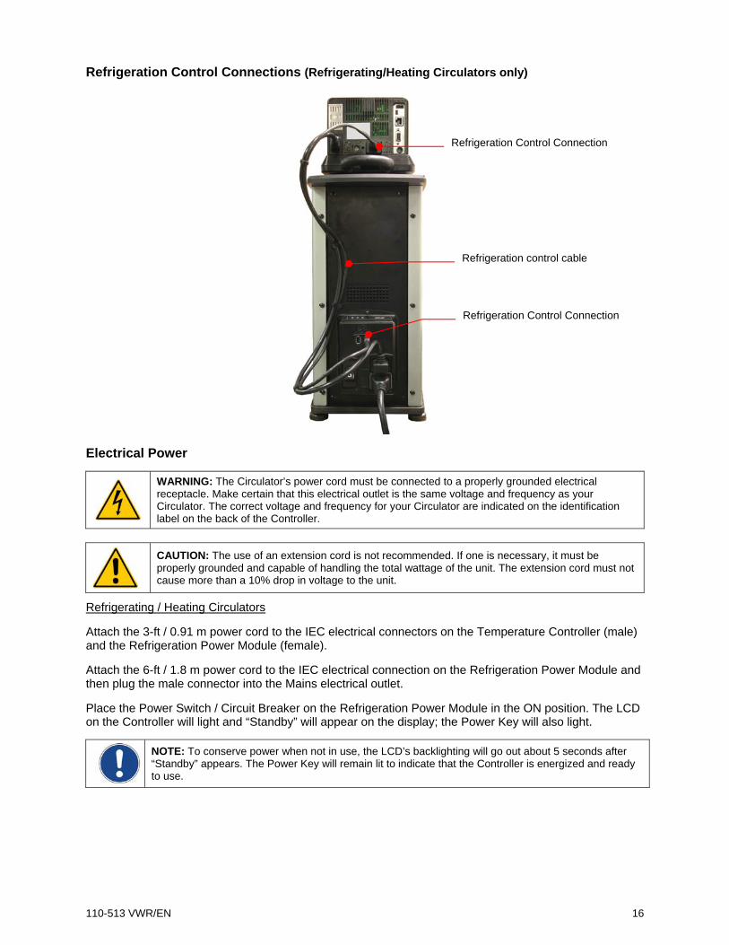
Refrigeration Control Connections (Refrigerating/Heating Circulators only)
Electrical Power
WARNING: The Circulator’s power cord must be connected to a properly grounded electrical receptacle. Make certain that this electrical outlet is the same voltage and frequency as your Circulator. The correct voltage and frequency for your Circulator are indicated on the identification label on the back of the Controller.
CAUTION: The use of an extension cord is not recommended. If one is necessary, it must be properly grounded and capable of handling the total wattage of the unit. The extension cord must not cause more than a 10% drop in voltage to the unit.
Refrigerating / Heating Circulators
Attach the 3-ft / 0.91 m power cord to the IEC electrical connectors on the Temperature Controller (male) and the Refrigeration Power Module (female).
Attach the 6-ft / 1.8 m power cord to the IEC electrical connection on the Refrigeration Power Module and then plug the male connector into the Mains electrical outlet.
Place the Power Switch / Circuit Breaker on the Refrigeration Power Module in the ON position. The LCD on the Controller will light and “Standby” will appear on the display; the Power Key will also light.
NOTE: To conserve power when not in use, the LCD’s backlighting will go out about 5 seconds after “Standby” appears. The Power Key will remain lit to indicate that the Controller is energized and ready to use.
Refrigeration Control Connection
Refrigeration Control Connection
Refrigeration control cable

110-513 VWR/EN 17
Heat Only Circulators
Attach the 6-ft / 1.8 m power cord to the IEC electrical connection on the Temperature Controller and then plug the male connector into the Mains electrical outlet.
Place the Power Switch / Circuit Breaker on the Temperature Controller in the ON position. The LCD on the Controller will light and “Standby” will appear on the display; the the Power Key will also light.
NOTE: To conserve power when not in use, the LCD will go black about 5 seconds after “Standby” appears. The Power Key will remain lit to indicate that the Controller is energized and ready to use.
IEC Power Connection to Refrigeration Power Module
IEC Power Connection to Mains
IEC to IEC Power Cord
Refrigeration Power Module
IEC Power Connection to Controller
IEC to Mains Power Cord Power Switch / Circuit Breaker

110-513 VWR/EN 18
Communication The Advanced Digital Controller features a variety of connectivity options. Following are some typical ways you can use them to monitor and control the operation of your Circulator.

110-513 VWR/EN 19
USB Communication
Two USB ports (A and B) are provided on the rear of the Temperature Controller. USB A is intended for use with a flash drive and allows you to easily log temperature data. USB B allows you to remotely monitor and control your Circulator using a computer. See Normal Operation, Selecting a Remote Communication and Control Protocol and the Technical Information section of this manual for additional information.
Ethernet
An Ethernet port is provided on the back of the Temperature Controller to enable you to connect your Circulator to a computer network. See Normal Operation, Selecting a Remote Communication and Control Protocol and the Technical Information section of this manual for additional information,
RS232 / RS485 Serial Communication
CAUTION: Always turn electrical power to the Circulator OFF before making a connection to the serial (DB9) port.
Your Circulator features RS232 / RS485 serial communication for remote data logging and control capability. A DB9 connector is provided on the rear of the Temperature Controller for this purpose. See Normal Operation, Selecting a Remote Communication and Control Protocol and the Technical Information section of this manual for additional information.
The serial interface should be connected to a serial communication port on a remote PC using an appropriate cable. Information on the RS232 / RS485 command and communication protocol can be found in the Technical Information section of this manual.
External (P2) Temperature Probe
Your Circulator is capable of controlling temperature based on either the temperature of the internal bath or that of an external vessel or device. The connection for the optional external temperature probe is on the rear of the Temperature Controller. The Temperature Controller automatically detects the external temperature probe when it is connected. See Replacement Parts & Accessories for available lengths and part numbers.
Pin Out Diagrams — External (P2) Temperature Probe Connection
RTD SENSOR: 4 WIRE CIRCUIT, 100 OHMS @ 0 DEGREES C,
MAXIMUM OPERATING TEMPERATURE @ 200 C, CLASS A 0.003850 OHMS/DEGREES C.

110-513 VWR/EN 20
Controller Setup
Power
Press . The Circulator will begin running, actual and set point temperatures will be displayed, and the word “SET” will be continuously lit. The pump symbol will also be lit and the heating or refrigerating symbol may be lit or flashing.
Internal (P1) control only – external probe (P2) not connected
Heating symbol
Pump symbol
Refrigeration symbol
Control probe
Actual bath temperature
Set point temperature

110-513 VWR/EN 21
Safety Set Temperature
This is a “Do Not Exceed” temperature setting for your Circulator and is the temperature at which the heater will be turned OFF should the liquid level in the bath drop too low or the heater malfunctions. It is normally set about 5° higher than the desired operating temperature. Setting the Safety Set temperature is a simple 3-step procedure.
WARNING: The Safety Thermostat is user-adjustable from approximately 100° to 220°C / 312° to 428°F. Do not force the indicator dial beyond the stops at either end of the dial’s range.
1. Press the key until SAFETY appears.
2. Using a No.1 Philips head screwdriver, rotate the Safety Thermostat on the rear of the Temperature Controller until the desired Safety Set Temperature is displayed (clockwise to increase; counter-clockwise to decrease).
3. Press to return to the main operational screen.
Current Safety Set Temperature Safety Set
sub-menu
Safety Set Thermostat

110-513 VWR/EN 22
Normal Operation Keys and Controls
Power
Turns the Circulator’s Temperature Controller ON.
Home
Returns the LCD to the Main Operational Display (from any screen).
Menu
Accesses the Temperature Controller’s set-up sub-menus. The items in these sub-menus are used to configure the Controller’s general operational parameters (temperature unit, pump speed, upper and low temperature limits, etc. (see Set-up Sub-Menus, below).
SET
Used in conjunction with the Touch Scroll Bar to change the set point temperature and some operational parameters.
Touch Scroll Bar
Used to make temperature set point and other operational changes. Slide finger up / down scroll bar or touch upper / lower sections to make minor adjustments; hold your finger on the scroll bar to make large adjustments.
Turning Your Circulator ON
Press the key.
When the Circulator begins running, the actual and set point temperatures will be displayed and the pump symbol will be lit. If the optional external temperature probe is connected, a temperature value will also be displayed along the bottom of the screen. This is the bath temperature measured by the non-controlling (monitor) probe.
If the actual bath temperature is lower than the set point temperature, the heat symbol will also be lit.
Refrigerating/Heating Models: If the actual bath temperature is higher than the set point temperature, the refrigerating symbol will be lit. It is normal for both the heating and refrigerating symbols to be lit simultaneously when nearing or maintaining the set point temperature.

110-513 VWR/EN 23
Main Operational Display (Home)
This is the Circulators main operational display. You can return to this screen at any time by pressing the key.
Internal (P1) control only – external probe (P2) not connected
Internal (P1) control – external probe (P2) connected
Heating symbol
Control probe (internal or external)
Pump symbol
Refrigeration symbol
Actual fluid temperature as measured by control probe
Set point temperature
Monitoring probe ID P2 = External
Bath temperature as measured by monitoring probe

110-513 VWR/EN 24
External (P2) control
Bath temperature as measured by monitoring probe
Monitoring probe ID P1 = Internal

110-513 VWR/EN 25
Set-Up Sub-Menus
Pressing the key accesses and scrolls through the Temperature Controller’s set-up sub-menus. The Touch Scroll Bar is used to change the current setting / value in the sub-menus.
Sub-Menu Description Selection / Range Factory Default
UNIT Unit in which temperature is set and displayed °C or °F °C
PUMP Pump speed Variable – 50 to 100 70
HI LIM High limit temperature 25° to 202°C / 80° to 395°F 202°C / 395°F
LO LIM Low limit temperature -52° to 20°C / -61° to 65°F -52°C / 65°F
SET DIFF Maximum allowable difference between the measured internal and external temperatures
2° to 50°C 10°C
AUTOCOOL Temperature at which refrigeration is activated 1° to 150°C 45°C
SHC The specific heat capacity of the bath fluid 0.10 to 2.00 1.00
CONTROL Internal or external temperature control P1 (Internal) or P2 (External) P1
OFFSET / CALIBRATION Calibration or display offset value Password required -3.0°C to +3.0°C 0.0°C
SAFETY Safety Set Temperature ~40° to 240°C N/A
COM Remote communication and control RS232, RS485, USB, Ethernet RS232
TIMER Count down timer with audible signal 1 second to 999 minutes, 59 seconds
000:00
PASSWORD Permits access to Calibration and Diagnostic screens
10 = Diagnostic screen 12 = Access Calibrate
0
USB LOG Turns data logging On and Off No (Off) or Yes (On) No (Off)
ENGLISH Language in which information will be displayed
English, French, German, Spanish English
pODO Operational hours on pump Display only N/A cODO Operational hours on compressor Display only N/A
AUTO-ON Determines how unit will restart after a disruption in electrical power ON or OFF OFF
To accept a value in a sub-menu, press , , , or allow the LCD to return to the main operational display ( approximately 10 seconds).

110-513 VWR/EN 26
Adjusting the Temperature Set Point
This is the temperature at which the fluid in your Circulating Bath will be maintained. It may be set to one-hundredth of a degree over a range of -50.00° to +200.00°C / -58.00° to +390°F. The factory default set point is +20.0°C / +68.0°C.
To Change: Press . The arrow around the word “SET” will begin flashing. To make changes of one degree or more, touch the scroll bar until the desired set point temperature is displayed. To make changes of less than a degree, (e.g.,0.50°C), press
a second time. The decimal point will begin flashing. Touch the scroll bar until the desired value is displayed.
To Accept: Press , , , or allow the LCD to return to the main operational display (approximately 10 seconds).
NOTE: An audible alarm and the words Low Limit or High Limit flashing on the display indicate that the temperature set point value is outside the Low Limit or High Limit value. The Circulator will continue to heat/cool until the actual bath temperature reaches the Limit value, at which point operation will stop.
Press SET once to change whole degree values Press SET twice to make changes of less than a degree (decimal point will flash)
Touch and hold up/down arrows to make large changes Touch and release arrows or slide finger up/down scroll bar to make small changes

110-513 VWR/EN 27
Selecting the Temperature Unit
The temperature units sub-menu (°C / °F) allows you to select the temperature unit in which the actual bath temperature and set point temperature are displayed. The factory default is °C.
To Access: Press the key until UNIT is displayed.
To Change: To select °F, touch the bottom portion of the scroll bar; to select °C, touch the top portion of the scroll bar.
To Accept: Press , , , or allow the LCD to return to the main operational display (approximately 10 seconds).
Touch top for degrees C Touch bottom for degrees F

110-513 VWR/EN 28
Selecting the Pump Speed
This sub-menu allows you to set your Circulator’s pump speed. The pump speed range is 50 to 100; the factory default is 70.
To Access: Press the key until PUMP is displayed.
To Change: Touch the scroll bar until the desired pump speed is displayed (50 minimum, 100 maximum).
To Accept: Press , , , or allow the LCD to return to the main operational display (approximately 10 seconds).
Touch and hold up/down arrows to make large changes Touch and release to make minor changes

110-513 VWR/EN 29
Setting the High Limit Temperature
This sub-menu allows you to limit how high the temperature set point may be set. It also serves as a high limit safety, alerting you if bath temperature rises above the high limit temperature setting. The High Limit value may be set from +25° to +202°C / +80° to +395°F; the factory default is 202°C.
To avoid an unwanted shutdown during regular operation, the High Limit value should be set at least 5° higher than the selected control temperature.
To Access: Press the key until HI LIMIT is displayed.
To Change: Touch the scroll bar until the desired high limit temperature is displayed.
To Accept: Press , , , or allow the LCD to return to the main operational display (approximately 10 seconds).
Touch and hold up/down arrows to make large changes Touch and release to make minor changes

110-513 VWR/EN 30
Setting the Low Limit Temperature
This sub-menu allows you to limit how low the temperature set point may be set. It also serves as a low limit safety, alerting you if bath temperature falls below the low limit temperature setting. The Low Limit value may be set from -52° to +20°C / -61° to +65°F; the factory default is -52°C.
To avoid an unwanted alarms or shutdown during regular operation, the Low Limit value should be set at least 5° lower than the selected control temperature.
To Access: Press the key until LO LIMIT is displayed.
To Change: Touch the scroll bar until the desired low limit temperature is displayed.
To Accept: Press , , , or allow the LCD to return to the main operational display (approximately 10 seconds).
Touch and hold up/down arrows to make large changes Touch and release to make minor changes

110-513 VWR/EN 31
Setting the Differential Temperature This sub-menu is for use when external temperature control (P2) is being used. It establishes the maximum allowable differential between the external and internal measured temperatures and is intended prevent uncontrolled heating or cooling should the external temperature probe be dislodged or fail. The differential temperature may be set from 2° to 50°C; the factory default is 10°C.
To Access: Press the key until SET DIFF is displayed.
To Change: Touch the scroll bar until the desired until the desired P2 - P1 (external – internal ) temperature differential displayed.
To Accept: Press , , , or allow the LCD to return to the main operational display (approximately 10 seconds).
CAUTION: The Differential Temperature value is always shown in degrees C, even if degrees F is selected as the temperature unit in which the control and actual bath temperatures are displayed.
Touch and hold up/down arrows o make large changes Touch and release to make minor changes

110-513 VWR/EN 32
Setting the Auto Cool Temperature This sub-menu is displayed only on Refrigerating / Heating Circulators. It determines the set point temperature at which refrigeration will be activated and permits more precise control when operating at high temperatures as well as more rapid cool downs. For most applications, a set point that is 15 C above room temperature is recommended. The Auto Cool control range is from +1 C to 150 C. The refrigeration system will turn on when the bath temperature set point (150°C maximum) is below the Auto-Cool set point. The factory default is 45°C.
Cool Command™ Refrigeration — -40°C 7 liter Refrigerating/Heating Circulators and 15 liter and larger Refrigerating/Heating Circulators feature the Cool Command™ modulating refrigeration control system. Cool Command allows the refrigeration system to turn on at a fluid temperature up to 150 C when the temperature set point is changed to or below the Auto Cool set point (150°C maximum). As a result, bath fluid cools more quickly.
Conventional Refrigeration — -20°C 7 liter Refrigerating/Heating Circulators use a conventional refrigeration system. The refrigeration system will turn on when the bath fluid temperature and set point are below the Auto Cool set point (85°C maximum).
To Access: Press the until AUTOCOOL is displayed.
To Change: Touch the touch scroll bar or touch the arrow symbols until the desired auto cool temperature is displayed.
To Accept: Press , , , or allow the LCD to return to the main operational display (approximately 10 seconds).
Touch and hold up/down arrows to make large changes Touch and release to make minor changes

110-513 VWR/EN 33
Setting the Specific Heat Capacity (SHC) This sub-menu allows you to tune the Circulator’s control algorithm for the specific heat capacity (SHC) of the fluid you are using. The factory default is 1.00.
To Access: Press the key until SHC is displayed.
To Change: Touch the touch scroll bar or touch the arrow symbols until the desired specific heat capacity value is displayed.
To Accept: Press , , , or allow the LCD to return to the main operational display (approximately 10 seconds).
Touch and hold up/down arrows to make large changes Touch and release to make minor changes

110-513 VWR/EN 34
Selecting Internal or External Temperature Control
This sub-menu lets you determine whether temperature control will be based on the fluid temperature within the Circulator’s reservoir or the fluid temperature at an external device.
To Access: Press the key until CONTROL is displayed.
To Change: Touch the scroll bar until the desired temperature probe is displayed. P1 = Internal; P2 = External.
To Accept: Press , , , or allow the LCD to return to the main operational display (approximately 10 seconds).
If P2 is selected but an external temperature probe is not connected to the Temperature Controller, P2 UNPLUGGED will appear on the display.
Touch top for P1 (internal) Touch bottom for P2 (external)

110-513 VWR/EN 35
Calibrating Your Circulator (Offset)
These two sub-menus allow you to match the Circulator’s internal and/or external temperature probe to an external reference thermometer. A value from -3.0°C to +3.0°C may be entered; the factory default is 0.0°C.
CAUTION: The Offset Calibration value is always shown in degrees C, even if degrees F is selected as the temperature unit in which the control and actual bath temperatures are displayed. Your Circulator will automatically convert the °C offset calibration value to the correct °F display offset value.
NOTE: If you attempt to calibrate the Circulator when OFFSET is displayed, Password! will appear at the bottom of the screen. To proceed, advance to the PASSWORD sub-menu, enter 12, and then return to this sub-menu.
Protected – Password Required
Unlocked
To Access: Press the key until the calibration sub-menu for the temperature probe you wish to calibrate (P1 or P2) is displayed. If this function has been locked, OFFSET will appear and must be unlocked before changes can be made; if this function has been unlocked, CALIBRATE will appear.
To Change: Touch the scroll bar or touch the arrow symbols until the desired calibration temperature displayed.
To Accept: Press , , , or allow the LCD to return to the main operational display (approximately 10 seconds).
Touch top arrow to increase offset Touch bottom arrow to decrease offset

110-513 VWR/EN 36
Displaying the Safety Set Temperature This display shows the current Safety Set Temperature.
NOTE: If you attempt to set the Safety Set temperature using the scroll bar, Rear Adjust will appear at the bottom of the screen. Use the Safety thermostat on the rear of the Temperature Controller to adjust the Safety Set temperature.
To Access: Press the key until SAFETY is displayed.
To Change: This is a display only. The Safety Set Temperature is changed using the Safety thermostat on the rear of the temperature controller. The temperature value shown on the display will change as the thermostat is adjusted.
To Exit: Press , , , or allow the LCD to return to the main operational display (approximately 10 seconds).

110-513 VWR/EN 37
Selecting a Remote Communication and Control Protocol This sub-menu allows you to select the protocol you want to use for remote communication and control. The choices are RS232, addressable RS485, USB, and Ethernet; the factory default is RS232.
To Access: Press the key until COM and the currently selected protocol appears on the display.
To Change: To select RS232, touch the down arrow; to select Ethernet, touch the top arrow. RS485 and USB protocols are selected by touching areas on the scroll bar that lie between the two arrows.
To Accept: Press , , , or allow the LCD to return to the main operational display (approximately 10 seconds).
CAUTION: Although you can accept the displayed protocol by pressing either the Home, Menu, or SET keys, we recommend using the Menu key the first time a protocol is selected as there are additional parameters that must be configured when RS232, RS485, or Ethernet is selected. This will ensure that you are prompted to configure those parameters. See Technical Information, RS232/RS485 Configuration and Technical Information, Ethernet Configuration for additional information.
NOTE: See Technical Information, USB Setup, Monitoring, and Control for information on controlling your Circulator via the USB-B port.
Touch top arrow for Ethernet Touch areas between the arrows for USB and RS485 Touch bottom arrow RS232

110-513 VWR/EN 38
Using the Timer This sub-menu allows you to set and activate the Temperature Controller’s count-down timer. Any time duration from 1 second to 999 minutes, 59 seconds can be entered.
To Access: Press the key until TIMER is displayed.
To Change: Touch the scroll bar until the desired time duration is displayed.
To Start the Timer: Press , The timer will begin counting down.
To Pause the Timer: Press . The display will revert to the main operational display. To restart the timer, return to the Timer sub-menu and press .
The timer counts down in one second increments until it reaches 000:00. At this point, the time display flashes and an audible signal is activated. Press to acknowledge and deactivate.
NOTE: You can access other menu functions while the timer is running without affecting the count down.
Touch and hold up/down arrows to set long durations Touch and release set short durations changes

110-513 VWR/EN 39
Entering a Password This sub-menu allows access to the Calibration and Diagnostic sub-menus.
To Access: Press the key until PASSWORD is displayed.
To Change: Touch the scroll bar until the password needed to access the desired sub-menu is displayed. Calibration = 12; Diagnostic = 10)
To Accept: Press , , , or allow the LCD to return to the main operational display (approximately 10 seconds).
IMPORTANT: Once a password has been entered and accepted, the function it enables stays unlocked until either a new password is entered or the Circulator is turned OFF.
Touch arrows to enter the numeric password
110-513 VWR/EN 40
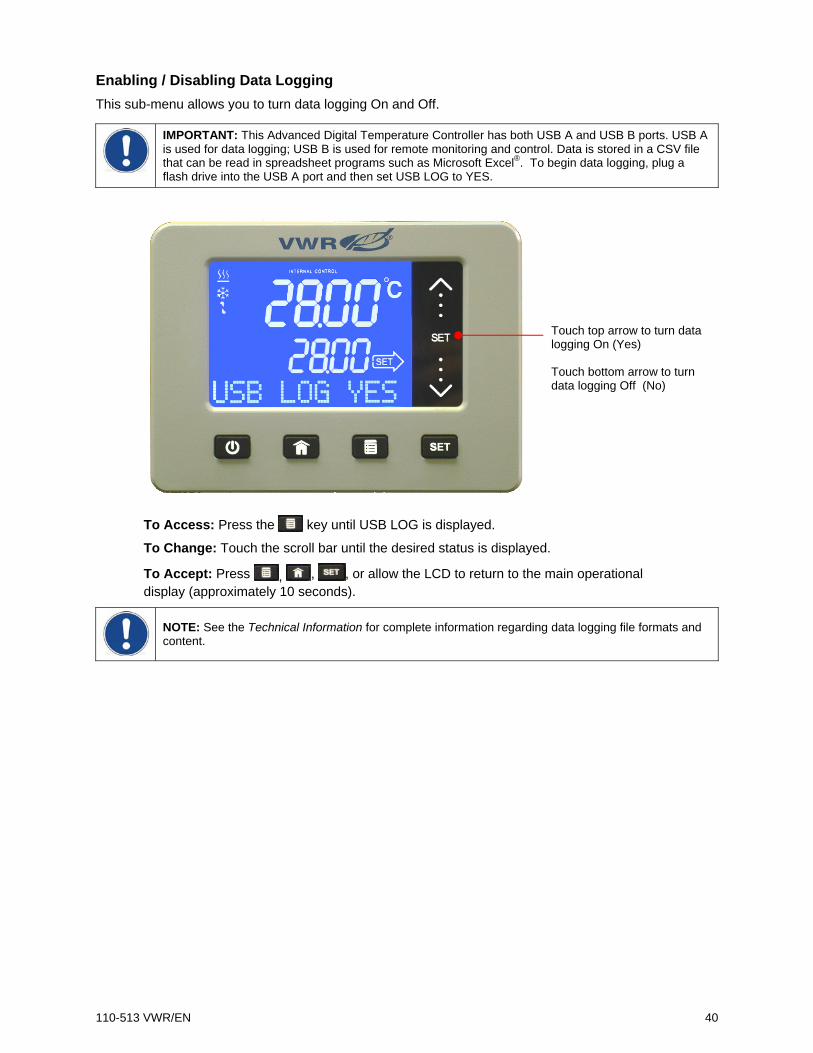
Enabling / Disabling Data Logging This sub-menu allows you to turn data logging On and Off.
IMPORTANT: This Advanced Digital Temperature Controller has both USB A and USB B ports. USB A is used for data logging; USB B is used for remote monitoring and control. Data is stored in a CSV file that can be read in spreadsheet programs such as Microsoft Excel®. To begin data logging, plug a flash drive into the USB A port and then set USB LOG to YES.
To Access: Press the key until USB LOG is displayed.
To Change: Touch the scroll bar until the desired status is displayed.
To Accept: Press , , , or allow the LCD to return to the main operational display (approximately 10 seconds).
NOTE: See the Technical Information for complete information regarding data logging file formats and content.
Touch top arrow to turn data logging On (Yes) Touch bottom arrow to turn data logging Off (No)

110-513 VWR/EN 41
Selecting the Operational Language This sub-menu allows you select the language in which information will be displayed. The choices are English, Spanish, French, and German; the factory default is English.
To Access: Press the key until the current language is displayed.
To Change: Touch the scroll bar until the desired language is displayed.
To Accept: Press , , , or allow the LCD to return to the main operational display (approximately 10 seconds).
Touch top arrow to scroll up through language list Touch bottom arrow to scroll down through language list

110-513 VWR/EN 42
Setting Auto Restart
WARNING: The unit may start automatically after a disruption in electrical power.
This sub-menu allows you to select how the unit will begin operating after a disruption in electrical power. When Yes is selected, the Circulator will begin running automatically when power is restored. When No is selected, the Circulator will power up in the Standby mode.
To Access: Press the key until AUTO-ON is displayed.
To Change: Touch the bottom of the scroll bar to select Yes (ON); touch the top of the scroll bar to select No (OFF).
To Accept: Press , , , or allow the LCD to return to the main operational display (approximately 10 seconds).
Resetting the Factory Default Values
To reset your Circulator to its original factory default values, proceed as follows:
1. Press the key to place the unit in Standby.
2. Place the Power Switch / Circuit Breaker in the Off position.
3. Return the Power Switch / Circuit Breaker to the On position while pressing the key until “STANDBY” appears on the display.
4. Press the key.
Touch top arrow to turn Auto-On OFF Touch bottom arrow to turn ON

110-513 VWR/EN 43
Changing Your Circulator’s Viewing Angle
Your Circulator is equipped with Swivel 180™, an innovative feature which permits viewing of the temperature display from anywhere within a 180° radius.
NOTE: There are positive stops at 45° intervals; however, the viewing angle may be set anywhere within a 180° radius.
To change the viewing angle, slide the release latch to the right and rotate the Temperature Controller to the desired angle. The latch release will automatically return to the locked position at every 45° positive stop.
Inert Gas Purge
A 0.125 in. / 3 mm port on the rear of the Temperature Controller is provided to allow you to blanket the surface of the liquid in the bath reservoir with nitrogen or another inert gas to help prevent condensation and dilution of the bath fluid.
Tap Water Cooling
Tap water cooling allows for more rapid bath cool down from high temperatures and/or more precise operation at temperatures near ambient.
Heat only Circulating Baths feature an integrated cooling coil as standard equipment. The tap water connections are made on the rear of the unit. Two 0.25 inch / 6.4 mm female NPT fittings are provided for these connections.
WARNING: The fluid outlet must be connected and flow to a suitable drain or vessel located at a level below that of the inlet.
Reservoir Cover Storage
Refrigerating/Heating and Heat Only Circulating Baths feature the LidDock® system to eliminate mess when adding fluid or samples to the reservoir. Specially positioned notches in the inner lip of the top deck allow you to stand the reservoir cover up upright over the bath opening, allowing condensate to flow back into the bath.
Swivel 180™ latch release
Lid Positioning Notch
Lid Positioning Notch

110-513 VWR/EN 44
Display Messages and Alarms Message and/or
Symbol Description Corrective Action
POWER FAILED Informational: Indicates that electrical power was lost during operation; appears only when Auto-On is set to Yes.
Press key to clear the message.
WARNING! LO LIMIT!
Warning: The fluid temperature or temperature set point is below the Low Limit value. (Message flashes, audible beep)
Decrease the Low Limit temperature value or increase the temperature set point. If problem is not corrected within about 30 seconds, the Circulator will go into a Low Limit Fault condition and operation will cease.
WARNING! HI LIMIT!
Warning: The fluid temperature or temperature set point is above the High Limit value. (Message flashes, audible beep)
Increase the High Limit temperature value or decrease the set point temperature. If problem is not corrected within about 30 seconds, the Circulator will go into a High Limit Fault condition and operation will cease.
FAULT! LO LIMIT!
Fault: The bath temperature has fallen below the Low Limit temperature value. Power to the compressor and pump will remain OFF until the problem is corrected. (Message flashes, continuous tone)
Press to turn power OFF. Restore power and then decrease the Low Limit temperature value or increase the temperature set point.
Controller failure; consult factory.
FAULT! HI LIMIT!
Fault: The bath temperature risen has above the High Limit temperature value. Power to the heater and pump will remain OFF until the problem is corrected. (Message flashes, continuous tone)
Press to turn power OFF. Restore power and then increase the High Limit temperature value or decrease the temperature set point. Controller failure; consult factory.
Fault: The liquid in the bath has dropped too low or the temperature of the bath fluid has exceeded the Safety Set temperature. Power to the heater will remain OFF until the problem is corrected.
Fluid level in reservoir has fallen below minimum level; add fluid as required. Fluid temperature is higher than Safety Set temperature; increase Safety Set temperature setting. Controller failure; consult factory.
FAULT! EXT PROBE 2
Fault: The external temperature probe has been disconnected. Appears only when using External Control. (Message flashes, continuous tone)
Reconnect external probe, turn power OFF and then back ON. If problem persists, replace external probe or operate using Internal Control.
Informational Messages — Do not disrupt normal operation. Clear by pressing the key.
Warnings — Circulator operation continues unless left uncorrected for approximately 30 seconds. Press the key to silence the audible signal. Correct problem and press the key a second time to clear Warning.
Faults — Circulator operation is halted (heater, pump, and compressor turn OFF). Press the key to silence the audible signal. Press to turn power OFF and then restore power and correct the problem.

110-513 VWR/EN 45
Routine Maintenance and Troubleshooting
WARNING: Always turn your Circulator OFF and disconnect it from the electrical power outlet before performing any maintenance or service.
WARNING: To avoid the potential for burns, allow the Circulator to cool completely before cleaning or performing any maintenance.
Maintaining Clear Bath Water
Optimum temperature and moisture conditions for algae growth exist when using water as a bath fluid. To prevent algae contamination and minimize the frequency of draining the reservoir, an algaecide should be used.
WARNING: Do not use chlorine bleach.
Draining the Bath Reservoir
WARNING: Bath fluids should be stored and disposed of according to applicable laws and regulations.
Refrigerated / Heating and Heat only Circulating Baths
Refrigerated / Heating and Heat only Circulating Baths are equipped with a drain valve and port located either beneath the front access panel or on the right hand side of the unit.
To drain fluid from the bath, attach a short length of suitable 11.5 mm ID / 0.45 inch ID tubing to the drain port and secure it using a hose clamp with a minimum ID of 18 mm / 0.7 inch. Open the drain valve using a flat blade screwdriver. When closing the valve, do not over tighten.
WARNING: Be sure to close the drain valve before refilling the bath reservoir. Do not over tighten.
Drain Valve Drain Port

110-513 VWR/EN 46
Checking the Over-Temperature / Low Liquid Level Safety Systems
Your Circulator incorporates over-temperature and low liquid level protection according to IEC 61010-2-010. For optimum safety, these systems should be checked at least every six months for proper operation. These checks must be performed with the unit running.
Over-Temperature Protection
1. Press until the Safety sub-menu is displayed.
2. Using a No.1 Philips head screwdriver, rotate the Safety Set
Thermostat on the rear of the Temperature Controller until the unit shuts down. The Safety Set temperature at this point should be the same as the actual bath temperature.
3. Return the Safety Set temperature to the desired over-temperature value.
4. Press the key to return to the Main Operational Display.
Low Liquid-Level Protection
1. Set the temperature set point to ambient and allow the Circulator to stabilize at that temperature.
2. Increase the temperature set point to about 5°C above ambient and slowly drain fluid from the bath.
3. Continue draining fluid until the unit shuts down. The fluid level at this point should be approximately 3.75 in. / 9.5 cm below the underside of the Circulator’s top deck.
4. Replace the bath fluid and return to normal operation.
Safety Set Temperature
Safety Set Thermostat

110-513 VWR/EN 47
Cleaning Your Circulator
WARNING: It is the user’s responsibility to properly decontaminate the unit in the event hazardous materials are spilled on exterior or interior surfaces. Consult the manufacturer if there is any doubt regarding the compatibility of decontamination or cleaning agents.
Temperature Controller
Turn the Temperature Controller OFF by pressing and unplug power cord from the electrical outlet.
Wipe the housing with a clean cloth dampened with a mild detergent and water or mild all-purpose cleaner.
CAUTION: Do not spray cleaning liquids directly onto the Temperature Controller or allow them to enter the Controller’s vents. Do not use abrasives as these could scratch the housing or the digital display.
Bath Reservoir
Bath Reservoir and Wetted Components — A vinegar solution or calcium/lime/rust remover can be used to clean mineral deposits from the Temperature Controller’s wetted parts. The cleaner should be added to the bath reservoir at the prescribed dosage and circulated at 60°C / 140°F until the scale is removed.
CAUTION: Do not use steel wool to clean your Circulator’s bath reservoir.
External Surfaces — Only mild detergents and water or an approved cleaner should be used on the top deck and other external surfaces of your Circulator. Do not allow cleaning liquids or sprays to enter the vents on the rear of the Temperature Controller.
Pump Impeller
In the unlikely event that debris becomes lodged in the pump impeller, a soft brush can be used to remove any lodged particles. If necessary, soak in a solution of distilled water and vinegar to soften before brushing.
CAUTION: Do not use hard utensils or abrasive pads to remove trapped debris.
Condenser, Air Vents, and Reusable Filter (Refrigerating / Heating Circulators only)
To keep the refrigeration system operating at optimum cooling capacity, the condenser, removable air filter, and all air vents (front, side, back) should be kept free of dust and dirt. Be sure to check them on a regular basis and clean as required.
The reusable filter is easily accessed from the front of the unit by simply removing the access panel. Use a mild detergent and water solution to wash off any accumulated dust and dirt. Rinse and dry thoroughly before reinstalling.
Reusable Filter

110-513 VWR/EN 48
Temperature Controller Removal and Re-Installation
Removal
The Temperature Controller on your Circulating Bath is designed to be easily removed from the top deck without the use of special tools. It is removed as follows:
1. Place the tip of a small flat blade screwdriver under the retaining ring locking tab and pry up gently.
2. Rotate the Temperature Controller clockwise until it stops (about 0.75 inch / 1.9 cm).
3. Lift the Controller straight up and out of the opening of the Circulator’s top deck.
Locking tab

110-513 VWR/EN 49
Re-Installation
The top deck of your Circulator incorporates four pins to facilitate positioning of the Temperature Controller when it is being reinstalled. These pins correspond to keyhole slots on the interior of the Circulator’s retaining ring.
1. With the retaining ring locking tab oriented above one of the indents on the top deck, slowly lower the Temperature Controller into the top deck opening until it is resting on top of the positioning pins.
2. Gently rotate the Temperature Controller until it drops down on the positioning pins.
3. Rotate the Temperature Controller in the counter-clockwise until the Locking Tab engages the
indent on the top deck.
Positioning Pins (4 total)
Keyhole Slot (cutaway)
Locking Tab
Indent

110-513 VWR/EN 50
Viewing Component Operating Time Your Circulator tracks pump and (on Refrigerating/Heating Circulators) compressor operation, This run time is initially tracked in hours and minutes and then in days. You can view this information by pressing the key until the pODO or cODO screen appears:
Pump Operating Time – (shown here in days)
Compressor Operating Time – (shown here in hours and minutes)
To Exit: Press , , , or allow the LCD to return to the main operational display (approximately 10 seconds).

110-513 VWR/EN 51
Troubleshooting Chart
Problem Possible Causes Corrective Action
Unit does not run (Digital Display is blank)
No power to unit Check that the electrical cord is secure and connected to an operating electrical outlet.
Unit does not run (STANDBY appears on Digital Display)
Unit in Standby mode Press Power Key on front panel.
No fluid circulation Insufficient fluid in reservoir Pump impeller jammed
Add fluid to reservoir. Inspect pump and remove debris as required.
Insufficient circulation Fluid viscosity too high External tubing diameter too small Low line voltage
Replace with lower viscosity bath fluid. Replace with larger diameter tubing. Check and correct as required.
Unit does not heat Insufficient fluid in reservoir Temperature set point too low Safety Set Temperature too low
Add fluid to reservoir. Increase temperature set point. Increase Safety Set temperature.
Insufficient heating Insufficient circulation Low line voltage Ambient temperature too cool Excessive heat loss
See Insufficient circulation, above. Check and correct as required. Increase ambient temperature or relocate unit. Check for heat loss from external tanks and hoses; Check for vapor/heat loss from internal reservoir.
Temperature unstable
Insufficient circulation Debris or mineral build-up on pump, heater, or temperature sensor.
Check pump flow and operation. Clean as required.
Unit does not cool Dust build up on air filter or condenser Blocked air ventilation screens Temperature set point is too high Excessive heat load Ambient air temperature too high (>35°C / 95°F) Low or high line voltage
Clean air filter and/or condenser as required. Remove blockages as required. Decrease temperature set point. Check that heat load does not exceed capacity of bath; correct as required. Decrease ambient air temperature. Check and correct as required.
110-513 VWR/EN 52
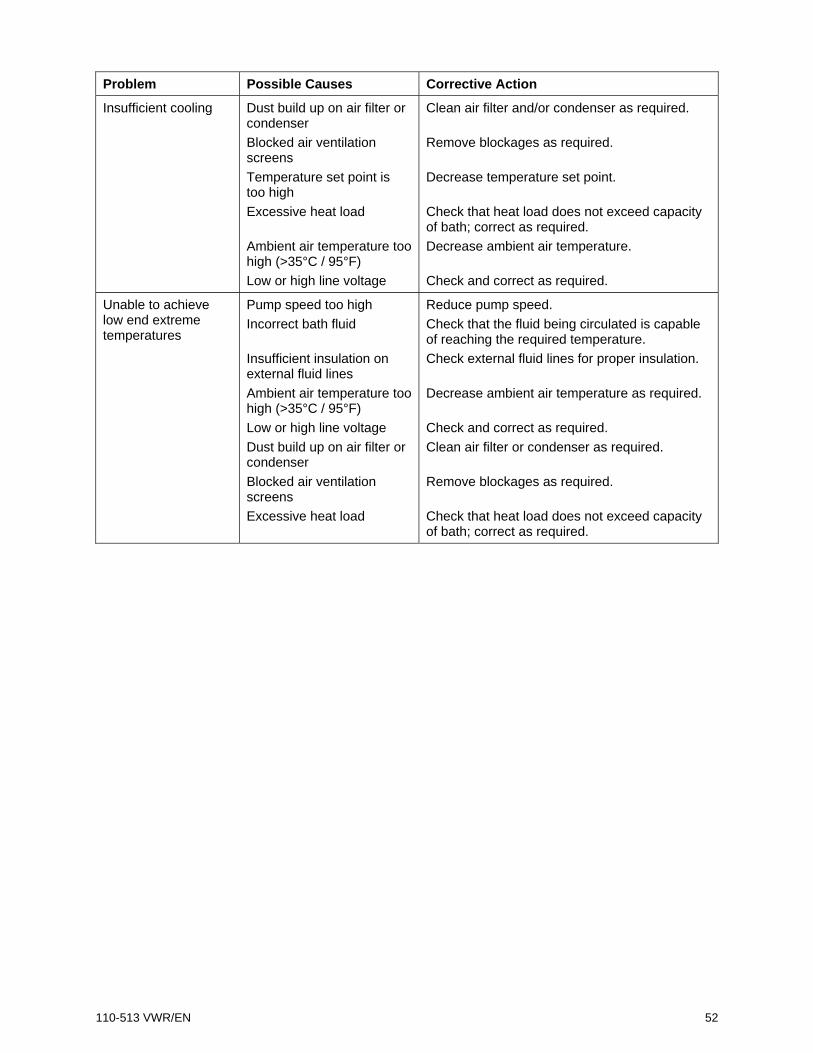
Problem Possible Causes Corrective Action
Insufficient cooling Dust build up on air filter or condenser Blocked air ventilation screens Temperature set point is too high Excessive heat load Ambient air temperature too high (>35°C / 95°F) Low or high line voltage
Clean air filter and/or condenser as required. Remove blockages as required. Decrease temperature set point. Check that heat load does not exceed capacity of bath; correct as required. Decrease ambient air temperature. Check and correct as required.
Unable to achieve low end extreme temperatures
Pump speed too high Incorrect bath fluid Insufficient insulation on external fluid lines Ambient air temperature too high (>35°C / 95°F) Low or high line voltage Dust build up on air filter or condenser Blocked air ventilation screens Excessive heat load
Reduce pump speed. Check that the fluid being circulated is capable of reaching the required temperature. Check external fluid lines for proper insulation. Decrease ambient air temperature as required. Check and correct as required. Clean air filter or condenser as required. Remove blockages as required. Check that heat load does not exceed capacity of bath; correct as required.

110-513 VWR/EN 53
Technical Information Performance Specifications
Operating Temperature Range: Model dependent; see table below
Temperature Stability: ±0.01C (±0.02°F)
Pump Type: Variable speed pressure/suction
60Hz models 50Hz models
Maximum Pressure: 4.3 psi (0.30 bar) 3.6 psi (0.25 bar)
Maximum Pressure Flow Rate: 5.3 gpm (20.1 lpm) 4.4 gpm (16.7 lpm)
Maximum Suction Flow Rate: 3.9 gpm (14.7 lpm) 3.2 gpm (12.2 lpm)
Heater Wattage: 1100 watts 2200 watts
Electrical Requirements Model Type Reservoir
Capacity Temperature
Range 60Hz Units 50Hz Units
AD07R-20 Refrigerating / Heating Bath 7 liters -20° to 200°C -4° to 392°F
120V, 60Hz, 12A
240V, 50Hz, 12A
AD07R-40 Refrigerating / Heating Bath 7 liters -40° to 200°C -40° to 392°F
120V, 60Hz, 12A
240V, 50Hz, 12A
AD7LR-20 Refrigerating / Heating Bath 7 liters -20° to 200°C -4° to 392°F
120V, 60Hz, 12A
240V, 50Hz, 12A
AD15R-30 Refrigerating / Heating Bath 15 liters -30° to 200°C -22° to 392°F
120V, 60Hz, 13A
240V, 50Hz, 13A
AD15R-40 Refrigerating / Heating Bath 15 liters -40° to 200°C -40° to 392°F
120V, 60Hz, 13A
240V, 50Hz, 13A
AD20R-30 Refrigerating / Heating Bath 20 liters -30° to 200°C -22° to 392°F
120V, 60Hz, 13A
240V, 50Hz, 13A
AD28R-30 Refrigerating / Heating Bath 28 liters -30° to 200°C -22° to 392°F
120V, 60Hz, 13A
240V, 50Hz, 13A
AD45R-20 Refrigerating / Heating Bath 45 liters -25° to 135°C -13° to 275°F
208-240V, 50/60Hz, 12A
208-240V, 50/60Hz, 12A
AD07H200 Heating Only Bath 7 liters Ambient +10° to 200°C Ambient +20° to 392°F
120V, 60Hz, 10A
240V, 50Hz, 10A
AD15H200 Heating Only Bath 15 liters Ambient +10° to 200°C Ambient +20° to 392°F
120V, 60Hz, 10A
240V, 50Hz, 10A
AD20H200 Heating Only Bath 20 liters Ambient +10° to 200°C Ambient +20° to 392°F
120V, 60Hz, 10A
240V, 50Hz, 10A
AD28H200 Heating Only Bath 28 liters Ambient +10° to 200°C Ambient +2°0 to 392°F
120V, 60Hz, 10A
240V, 50Hz, 10A
Environmental Conditions Indoor use only Maximum Altitude: 2000 meter Operating Ambient: 5° to 35°C (41° to 95°F) Relative Humidity: 80%, non-condensing Installation Category: II Pollution Degree: 2 Ingress Protection: IP 31 Climate Class: SN Software Class: B Output Waveform: Sinusoidal
Specifications subject to change without notice.

110-513 VWR/EN 54
Reservoir Fluids
Depending on your needs, a variety of fluids can be used with your Circulator. No matter what bath fluid is selected, it must be chemically compatible with the reservoir and the materials in your Circulator. It must also be suitable for the desired temperature range.
WARNING: When using Class III flammable fluids per DIN 12876-1, the user must attach the following warning labels to the front of the unit so that they are well visible:
Warning Label W09 Colors: Yellow/black
Danger Area. Attention! Observe instructions (operating manual, safety data sheet)
Mandatory Label M018 Colors: Blue/white
Carefully read the user information prior to beginning operation. Scope: EU
or
Semi S1-0701 Table A1-2 #9 Colors: Blue/white
Carefully read the user information prior to beginning operation. Scope: NAFTA
WARNING: Always use fluids that satisfy safety, health, and equipment compatibility requirements. Be aware of the chemical hazards that may be associated with the bath fluid used. Observe all safety warnings for the fluids used as well as those contained in the material safety data sheet.
For optimum temperature stability, the fluid’s viscosity should be 50 centistokes (cSt) or less at its lowest operating temperature. This permits good fluid circulation and minimizes heating from the pump.
For temperatures from 10°C to 90°C, distilled water is recommended. For temperatures below 10°C, a mixture of laboratory grade ethylene glycol and water should be used. Do not use deionized water.
WARNING: DO NOT USE THE FOLLOWING LIQUIDS
• Automotive antifreeze with additives**
• Hard tap water**
• Deionized water with a specific resistance > 1 meg ohm
• Concentrations of acids or bases
• Solutions with halides: chlorides, fluorides, bromides, iodides or sulfur
• Bleach (Sodium Hypochlorite)
• Solutions with chromates or chromium salts
• Glycerine
• Syltherm fluids
** At temperatures above 40°C, additives or mineral deposits can adhere to the heater. If deposits are allowed to build up, the heater may overheat and fail. Higher temperatures and higher concentrations of additives will hasten deposit build up.

110-513 VWR/EN 55
Application Notes
At a fluid's low temperature extreme:
• The presence of ice or slush adversely affects temperature stability. • A viscosity above 10 centistokes adversely affects temperature uniformity. • A high fluid viscosity and high pump speed adds heat to the fluid being pumped.
At a fluid's temperature above ambient without refrigeration:
• If your set point temperature is less than 15°C above the ambient temperature, the viscosity of the fluid should be 10 centistokes or less to minimize friction heating of the fluid.
• Heat loss should be encouraged by uncovering the fluid and lowering the pump speed.
At fluid's high temperature extreme:
• Heat loss from vapor adversely affects temperature stability. • To prevent the accumulation of vapors inside the room, the reservoir may need to be
placed in a fume hood. • Use a cover and/or floating hollow balls to help prevent heat and vapor loss. • Replenish fluid lost from vapor frequently.
Tubing and Fitting Temperature Ranges
Material Temperature Range
Buna N tubing -40° to 120°C
Viton® tubing -32° to 200°C
Braided Teflon® lined tubing -50° to 225°C
Stainless steel fittings -45° to 225°C
Nylon fittings -40° to 90°C
Brass fittings -40° to 80°C

110-513 VWR/EN 56
RS232/RS485 Configuration Selecting RS232 or RS485 Communication — Your Circulator may be configured for either RS232 or addressable RS485 serial communication. The selection is made on the COM sub-menu (see Normal Operation, Selecting the Remote Communication and Control Protocol).
To Access: Press the key until COM and the currently selected protocol appears on the display.
To Change: To configure the Circulator for RS232 communication, touch the down arrow; to configure the Circulator for RS485 communication, touch a point between the down arrow and the word SET.
To Accept: Press . You will prompted to select the communications baud rate.
Touch down arrow to select RS232
Touch point between down arrow and the word SET to select RS485

110-513 VWR/EN 57
Selecting the Communications Baud Rate — This sub-menu allows you to select the speed at which your Circulator will transmit data. The baud rate setting may be 1200, 2400, 4800, 9600, 19200, 38400, 57600, or 115200; the factory default is 9600.
NOTE: When using RS232/RS485 communication, the Circulator’s baud rate must match that of the connected device.
To Change: To select the 1200 baud rate setting, touch the bottom of the scroll bar; to select the 115200 setting, touch the top of the scroll bar. Rates between these two extremes are selected by touching the corresponding area of the scroll bar.
To Accept: Press . If you have selected RS232 communication, the Timer sub-menu will appear; if you have selected RS485 communication, you will be prompted to enter the desired RS485 address.
Entering the RS485 Address — When RS485 has been selected as the serial communications protocol, you will be prompted to enter the RS485 address after the baud rate has been selected. An address from 000 to 254 may be entered.
To Change: Touch the touch scroll bar or touch the arrow symbols until the desired RS485 address is displayed.
To Accept: Press , , , or allow the LCD to return to the main operational display (approximately 10 seconds).
Touch up arrow for fastest baud rate
Touch down arrow for slowest baud rate
Touch and hold up/down arrows to make large changes Touch and release to make minor changes

110-513 VWR/EN 58
RS232/RS485 Communications
CAUTION: Always turn electrical power to the Circulator OFF before making a connection to the serial (DB9) port.
Serial Connector — A DB9 connector is provided on the back panel of the Controller for RS232/RS485 data communication.
Pin RS232 RS485 1 2 TX A 3 RX 4 DTR 5 GND GND 6 DSR 7 RTS 8 CTS B 9
Serial Communications Protocol — The Controller uses the following serial communications settings:
Data bits — 8 Parity — None Stop bits — 1 Flow control — None Baud rate — Selectable (Controller/PC baud rates must match). 57600 is recommended.
Communications Commands — RS232 commands must be entered using the command only; RS485 commands must be entered using @ and the RS485 address (E.g., @001) followed by the actual command. All commands must be entered in the exact format shown. Do not send a [LF] (line feed) after the [CR] (carriage return). Be sure to follow character case exactly.
A response followed by an exclamation point (!) indicates that a command was executed correctly. A question mark (?) indicates that the Controller could not execute the command (either because it was in an improper format or the values were outside the allowable range). A response must be received from the Controller before another command can be sent. All responses are terminated with a single [CR].
IMPORTANT INFORMATION REGARDING SERIAL COMMANDS ENTERED OVER ETHERNET VIA USER DATAGRAM PROTOCOL (UDP): Only Read commands will be allowed when entering serial commands over Ethernet unless (1) Ethernet is configured as Unlocked and (2) the proper password is included as part of the serial command. See Configuring the Ethernet Connection.
Set commands entered over Ethernet must include Pxxx immediately following the serial command. For example, to change set point, enter the following command: SSiii.iiPxxx [CR] where:
SS = Set set point iii.ii = set point value P = password identifier xxx = password [CR] = carriage return

110-513 VWR/EN 59
Command Format Values Return Message
Set Command Echo SEi[CR] Echo: i = 1 No Echo: i = 0 ![CR]
Set Set Point SSiii.ii[CR] i = any integer from 0-9 ![CR]
Set On Off SOi[CR] On: i = 1 Off: i = 0 ![CR]
Set High Alarm SHiii[CR] i = any integer from 0-9 ![CR]
Set Low Alarm SLiii[CR] i = any integer from 0-9 ![CR]
Set Pump Speed SMi[CR] i = any integer from 5-100 in increments of 5 ![CR]
Set Restart Power Status SWi[CR] Restart: i = 1 Standby: i = 0 ![CR]
Set Internal / External Control SJi[CR] External: i = 1 Internal: i = 0
![CR]
Read Set Point Temperature RS[CR] iii.ii[CR]
Read Units of Operation RU[CR] C[CR] or F[CR]
Read Internal Temperature RT[CR] iii.ii[CR]
Read External Temperature RR[CR] iii.ii[CR]
Read Operating Status RO[CR] Running: i = 1 Standby: i = 0 i[CR]
Read High Alarm Setting RH[CR] iii[CR]
Read Low Alarm Setting RL[CR] iii[CR]
Read Pump Speed RM[CR] Low: i = 1 High: i = 2 i[CR]
Read Power Status RW[CR] i[CR]
Read Alarm Status RF[CR] No Faults: i = 0 Fault: i = 1 i[CR]
Read the Auto-Cool Set Point RA[CR] ii[CR]
Read the Firmware Version RB[CR] viiii[CR]

110-513 VWR/EN 60
USB Data Logging Data is stored in a CSV file that can be read in spreadsheet programs such as Microsoft Excel®. The data is output in the following format:
MIN.SEC [V] UNIT SET P1 P2 4 [v0013] C 10 15.19 14.89 4 [v0013] C 10 15.18 14.88
4.22 [v0013] C 10 15.03 14.71 4.23 [v0013] C 10 15.02 14.7 4.24 [v0013] C 10 15 14.69 4.25 [v0013] C 10 15 14.69 4.26 [v0013] C 10 14.99 14.68 4.27 [v0013] C 10 14.98 14.67
MIN.SEC = Minutes and seconds.
V = Firmware version.
UNIT = Selected temperature unit.
SET = Temperature set point
P1 = Fluid temperature as measured by the Internal probe
P2 = Fluid temperature as measured by the External probe (if connected)
NOTE: The time stamp on the first line of data represents the time when data began being logged. The time stamp will indicate 0.01 if data logging was enabled after a flash drive or computer was connected to the USB port. It will show a later time if data logging was enabled before the storage device was connected. In the example shown above, the flash drive was connected to the USB port 4 minutes after data logging was enabled.
USB B Setup, Monitoring, and Control The Advanced Digital Temperature Controller can be monitored and controlled using a personal computer connected to its USB B port.
Initial Setup
1. Plug the USB A connector of a USB A to USB B cable into an open USB port on the personal computer and plug the USB-B connector into the corresponding port on the Temperature Controller.
2. The computer operating system will automatically detect a new device and ask to install the drivers for the device. The drivers are located on the Resource Disk that came with your Temperature Controller.
3. Place the Resource Disk in the computers CD drive and install the drivers.
4. Determine the identity of the communications port your computer assigned to the Temperature Controller.
Monitoring and Control
When all connections have been made and drivers installed, you can monitoring and control the Temperature Controller using a terminal program and the active serial communications commands.

110-513 VWR/EN 61
Configuring the Ethernet Connection
NOTE: The Advanced Digital Controller’s supports Ethernet communication using User Datagram Protocol (UDP).
The Advanced Digital Controller may be connected directly to a laptop or desktop computer via its Ethernet connection or indirectly via your facility’s wired or wireless network. Either type of connection enables you to control and/or monitor the operation of your circulating bath using User Datagram Protocol (UDP). The Controller’s active serial communications commands are used to retrieve and/or change operational information.
Direct Computer to Controller Configuration
NOTE: If your computer is already connected to a wired network, you will not be able to directly connect it to your circulating bath’s Temperature Controller.
1. Open the utility that displays your computer’s available network connections. 2. Select an available wired connection. 3. Enter the following properties for the selected connection:
A. Internet protocol: TCP/IP B. IP address: any three sets of identical numbers (e.g., 111.111.111) followed by a single
digit (e.g., 111.111.111.5). C. Subnet mask: 255.255.255.0
4. Enter the IP address into your Controller as outlined in Fixed IP Addressing, below. Please note that the first three series of numbers in IP address on the Controller must match those entered in Step 3B, above. The last number does not have to match.
Wired or Wireless Network Configuration
The Advanced Digital Controller supports both dynamic (DHCP) and fixed IP configuration. With either type of IP configuration, it may be necessary to work with your IT department to ensure that both the network and your Controller are configured properly.
To Access: Press the key until COM and the currently selected protocol appears on the display.
To Change: Touch the up arrow to select Ethernet.
To Accept: Press . A screen allowing you to select whether only Read commands will be allowed or if both Read and Set commands will be allowed will appear.
Selects Ethernet

110-513 VWR/EN 62
SET LOCKED – Read Commands Only Permitted UNLOCK – Set and Read Commands Permitted
IMPORTANT: When Unlock is selected, a three digit numeric field will also appear. This field serves as a password that must be entered along with Set commands in order for the command to be executed.
For example, the serial command required to change set point via Ethernet is: SSiii.iiPxxx [CR] where:
SS = Set set point iii.ii = set point value P = password identifier xxx = password [CR] = carriage return
To Change: Use the touch scroll bar to change the displayed selection and, if Unlock is selected, also enter the password that will be used when executing Set commands over Ethernet. You may enter any numerical value from 100 to 255 as your password.
To Accept: Press . A screen displaying Fixed or dynamic (DHCP) Ethernet will appear.
To Change: Touch the down arrow to select Fixed IP; touch the up arrow to select DHCP IP.
To Accept: Press . The IP address for the selection will appear. If Fixed is selected, you will be allowed to change the IP address (see Fixed IP Addressing). If DHCP is selected, you will be allowed to view, but not change, the IP address (see Dynamic IP Addressing).
Fixed IP Addressing — If your Controller will be connected directly to a computer or your network uses fixed IP addressing, you must manually enter the IP address that will be used into your Controller. This is done as follows:
1. Select Fixed IP, select SET LOCKED or UNLOCKED, and then press . The IP address screen will be displayed.
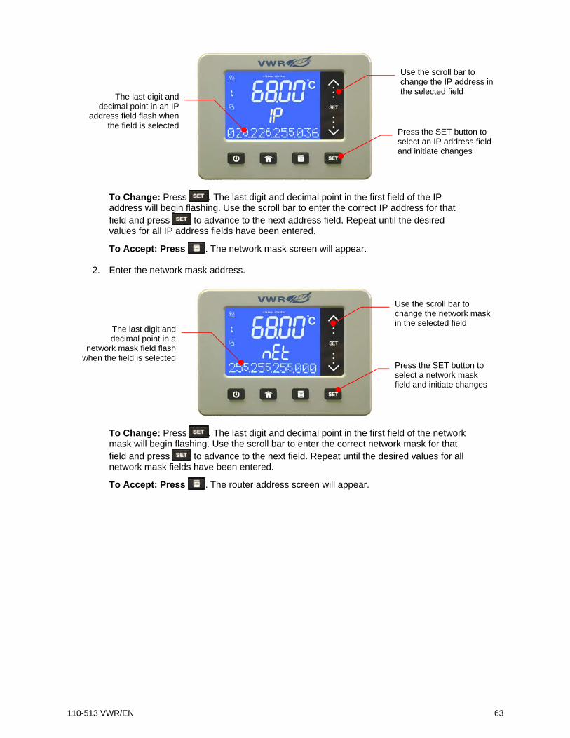
110-513 VWR/EN 63
To Change: Press . The last digit and decimal point in the first field of the IP address will begin flashing. Use the scroll bar to enter the correct IP address for that field and press to advance to the next address field. Repeat until the desired values for all IP address fields have been entered.
To Accept: Press . The network mask screen will appear.
2. Enter the network mask address.
To Change: Press . The last digit and decimal point in the first field of the network mask will begin flashing. Use the scroll bar to enter the correct network mask for that field and press to advance to the next field. Repeat until the desired values for all network mask fields have been entered.
To Accept: Press . The router address screen will appear.
Press the SET button to select an IP address field and initiate changes
Use the scroll bar to change the IP address in the selected field The last digit and
decimal point in an IP address field flash when
the field is selected
Use the scroll bar to change the network mask in the selected field
Press the SET button to select a network mask field and initiate changes
The last digit and decimal point in a
network mask field flash when the field is selected

110-513 VWR/EN 64
3. Enter the router address.
To Change: Press . The last digit and decimal point in the first field of the router address will begin flashing. Use the scroll bar to enter the correct router address for that field and press to advance to the next address field. Repeat until the desired values for all router address fields have been entered.
To Accept: Press . Dynamic IP Addressing — If your network uses DHCP (Dynamic Host Configuration Protocol), the IP address, network mask address, and router address will be assigned automatically. Addressing is assigned as follows:
1. Configure Ethernet communication as outlined in Wired or Wireless previously.
2. Turn power to the Controller OFF using the power switch / circuit breaker on the rear of the unit.
3. Turn power to the Controller back ON.
NOTE: This power down sequence is only required the first time the Controller is configured for DHCP.
To view the assigned addresses, select ETH DHCP, select SET LOCKED or UNLOCKED, and then press
. The IP address screen will appear. Continue pressing to scroll to the network mask and router address screens.
Use the scroll bar to change the router address in the selected field
Press the SET button to select a router address field and initiate changes
The last digit and decimal point in a router address field flash when
the field is selected
Press the SET button to advance to subsequent address screens.

110-513 VWR/EN 65
Equipment Disposal (WEEE Directive)
or
This equipment is marked with the crossed out wheeled bin symbol to indicate that this equipment must not be disposed of with unsorted waste.
Instead, it is your responsibility to correctly dispose of your equipment at lifecycle-end by handing it over to an authorized facility for separate collection and recycling. It’s also your responsibility to decontaminate the equipment in case of biological, chemical and/or radiological contamination, so as to protect from health hazards the persons involved in the disposal and recycling of the equipment
For more information about where you can drop off your waste equipment, please contact your local dealer from whom you originally purchased this equipment.
By doing so, you will help to conserve natural and environmental resources and you will ensure that your equipment is recycled in a manner that protects human health.
Service and Technical Support
Web Resources Visit the VWR’s website at www.vwr.com for: • Complete technical service contact information • Access to VWR’s Online Catalogue, and information about accessories and related products • Additional product information and special offers Contact us For information or technical assistance contact your local VWR representative or visit. www.vwr.com.

110-513 VWR/EN 66
Warranty VWR International warrants that this product will be free from defects in material and workmanship for a period of two (2) years from date of purchase. If a defect is present, VWR will, at its option, repair, replace, or refund the purchase price of this product at no charge to you, provided it is returned during the warranty period. This warranty does not apply if the product has been damaged by accident, abuse, misuse, or misapplication, or from ordinary wear and tear. For your protection, items being returned must be insured against possible damage or loss. This warranty shall be limited to the replacement of defective products. IT IS EXPRESSLY AGREED THAT THIS WARRANTY WILL BE IN LIEU OF ALL WARRANTIES OF FITNESS AND IN LIEU OF THE WARRANTY OF MERCHANTABILITY.

110-513 VWR/EN 67
Local VWR Offices in Europe and Asia Pacific
Austria VWR International GmbH Graumanngasse 7 1150 Wien Tel.: 01 97 002 0 Fax: 01 97 002 600 E-mail: [email protected]
Belgium VWR International bvba Researchpark Haasrode 2020 Geldenaaksebaan 464 3001 Leuven Tel.: 016 385 011 Fax: 016 385 385 E-mail: [email protected]
China VWR International China Co., Ltd Suite 1802 - 1803, Xing Ye Bank Mansion, No 168, 168 Jiangning Road Shanghai 200041, China Tel.: +86- 21 521 388 22 Fax: +86- 21 521 33 933 E-mail: [email protected]
Denmark VWR - Bie & Berntsen Transformervej 8 2730 Herlev Tel.: 43 86 87 88 Fax: 43 86 87 90 E-mail: [email protected]
Finland VWR International Oy Valimotie 9 00380 Helsinki Tel.: +358 9 80 45 51 Fax: +358 9 80 45 52 00 E-mail: [email protected]
France VWR International S.A.S. Le Périgares – Bâtiment B 201, rue Carnot 94126 Fontenay-sous-Bois cedex Tel.: 0 825 02 30 30 (0,15 EUR TTC/min) Fax: 0 825 02 30 35 (0,15 EUR TTC/min) E-mail: [email protected]
Germany VWR International GmbH Hilpertstrasse 20a D - 64295 Darmstadt Tel.: 0180 570 20 00* Fax: 0180 570 22 22* E-mail: [email protected] *0,14 €/Min. aus d. dt. Festnetz, Mobilfunk max. 0,42 €/Min.
Hungary VWR Spektrum-3D Kft. Simon László u. 4. 4034 Debrecen Tel.: (52) 521-131 Fax: (52) 470-069 E-mail: [email protected]
India VWR Lab Products Pte Ltd 2nd Floor, Front Wing, 135/12, Brigade Towers Brigade Road Bangaluru 560025 India Tel: +91-2522-277876 (Mumbai) Tel: +91-80-41117124 (Bangalore) Fax +91-80-41117120 E-mail: [email protected]
Ireland / Northern IrelandVWR International Ltd / VWR International (Northern Ireland) Ltd Orion Business Campus Northwest Business Park Ballycoolin Dublin 15 Tel.: 01 88 22 222 Fax: 01 88 22 333 E-mail [email protected]
Italy VWR International s.r.l. Via Stephenson 94 20157 Milano (MI) Tel.: 02 332 03 11 Fax: 800 152 999 E-mail: [email protected]
The Netherlands VWR International B.V. Postbus 8198 1005 AD Amsterdam Tel.: 020 4808 400 Fax: 020 4808 480 E-mail: [email protected]
Norway VWR International AS Haavard Martinsens vei 30 0978 Oslo Tel.: 02290 Fax: 815 00 940 E-mail: [email protected]
Poland Labart Sp. z o.o. A VWR International Company Limbowa 5 80-175 Gdansk Tel.: 058 32 38 210 Fax. 058 32 38 205 E-mail: [email protected]
Portugal VWR International - Material de Laboratório, Lda Edifício Neopark Av. Tomás Ribeiro, 43- 3 D 2790-221 Carnaxide Tel.: 21 3600 770 Fax: 21 3600 798/9 E-mail: [email protected]
Singapore VWR Singapore Pte Ltd 18 Gul Drive Singapore 629468 Tel: +65 6505 0760 Fax: +65 6264 3780 E-mail: [email protected]
Spain VWR International Eurolab S.L. C/ Tecnología 5-17 A-7 Llinars Park 08450 - Llinars del Vallès Barcelona Tel.: 902 222 897 Fax: 902 430 657 E-mail: [email protected]
Sweden VWR International AB Fagerstagatan 18a 163 94 Stockholm Tel.: 08 621 34 00 Fax: 08 621 34 66 E-mail: [email protected]
Switzerland VWR International AG Lerzenstrasse 16/18 8953 Dietikon Tel.: 044 745 13 13 Fax: 044 745 13 10 E-mail: [email protected]
UK VWR International Ltd Customer Service Centre Hunter Boulevard Magna Park Lutterworth Leicestershire LE17 4XN Tel.: 0800 22 33 44 Fax: 01455 55 85 86 E-mail: [email protected]