Embed Size (px)
DESCRIPTION
lecture notes
Citation preview

CIRCUIT THEORYEE2151
UNIT-1BASIC CIRCUITS ANALYSIS
IFET/EEE/CT/I YEAR/II SEM/EE2151/CT/VER 1.0
SYLLABUS
IFET/EEE/CT/I YEAR/II SEM/EE2151/CT/VER 1.0
Ohm’s Law Kirchoffs laws DC and AC Circuits Resistors in series and parallel circuitsMesh current and node voltage method of analysis for D.C and A.C.circuits.

SUMMARY OF SI UNITS
IFET/EEE/CT/I YEAR/II SEM/EE2151/CT/VER 1.0

UNIT PREFIXES USED IN SCIENTIFIC NOTATION
IFET/EEE/CT/I YEAR/II SEM/EE2151/CT/VER 1.0

ELECTRICAL POTENTIAL:Voltage, electromotive force (emf), or potential
difference, is described as the pressure or force that causes electrons to move in a conductor. In electrical formulas and equations, you will see voltage symbolized with a capital E, while on laboratory equipment or schematic diagrams, the voltage is often represented with a capital V.
ELECTRICAL QUANTITIES
ELECTRIC CURRENT:Electron current, or amperage, is described as the movement of free electrons through a conductor. In electrical formulas, current is symbolized with a capital I, while in the laboratory or on schematic diagrams, it is common to use a capital A to indicate amps .
IFET/EEE/CT/I YEAR/II SEM/EE2151/CT/VER 1.0
VOLTAGE
Alessandro Volta1745-1827
Italian Physicist
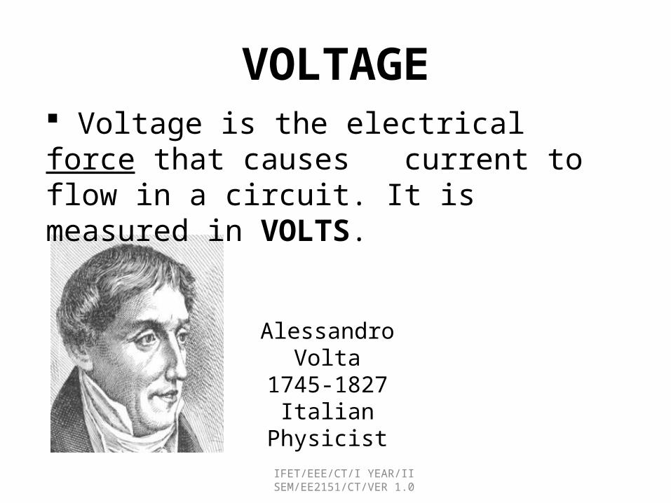
Voltage is the electrical force that causes current to flow in a circuit. It is measured in VOLTS.
IFET/EEE/CT/I YEAR/II SEM/EE2151/CT/VER 1.0

Current
Andre Ampere1775-1836
French Physicist
Current is the flow of electrical charge through an electronic circuit. Direction of a current is opposite to the direction of electron flow. Current is measured in AMPERES (AMPS).
IFET/EEE/CT/I YEAR/II SEM/EE2151/CT/VER 1.0

An Analogy
Force
Flow of water from one tank to another is a good analogy for an electrical circuit and the mathematical relationship between voltage, resistance, and current.
Force: The difference in the water levels ≡ Voltage
Flow: The flow of the water between the tanks ≡ Current
Opposition: The valve that limits the amount of water ≡ Resistance
Flow
Opposition

What is Voltage?
V = “Electrical pressure” - measured in volts.
H2O
High Pressure Low Pressure
IFET/EEE/CT/I YEAR/II SEM/EE2151/CT/VER 1.0

What is Current?
• Current is the flow of charge from a voltage source• 1 Ampere (“Amp”) = Flow of 1 Coulomb/sec
+++
IFET/EEE/CT/I YEAR/II SEM/EE2151/CT/VER 1.0

How Does Current Flow?
Current can only flow through conductors
+++
Metal wires (conductors)
Currentflow
IFET/EEE/CT/I YEAR/II SEM/EE2151/CT/VER 1.0

When Does Current NOT Flow?
+++
Plastic material (insulators)
Current cannot flow through insulators
No currentflow
IFET/EEE/CT/I YEAR/II SEM/EE2151/CT/VER 1.0

Note that Air is an Insulator
+++Air
Current cannot flow through insulators
No current flow
That’s why a battery doesn’t discharge if left on its own.
IFET/EEE/CT/I YEAR/II SEM/EE2151/CT/VER 1.0

ELECTRIC POWER:Power is the rate at which work is done.Unit electric power is watt.Power abbreviated with the capital letter P.Measure for power is abbreviated with the capital letter W.
P = I x EUsing Ohm’s Law for the value of voltage (E),E = I x Rand using substitution laws,P = I x ( I x R)
IFET/EEE/CT/I YEAR/II SEM/EE2151/CT/VER 1.0
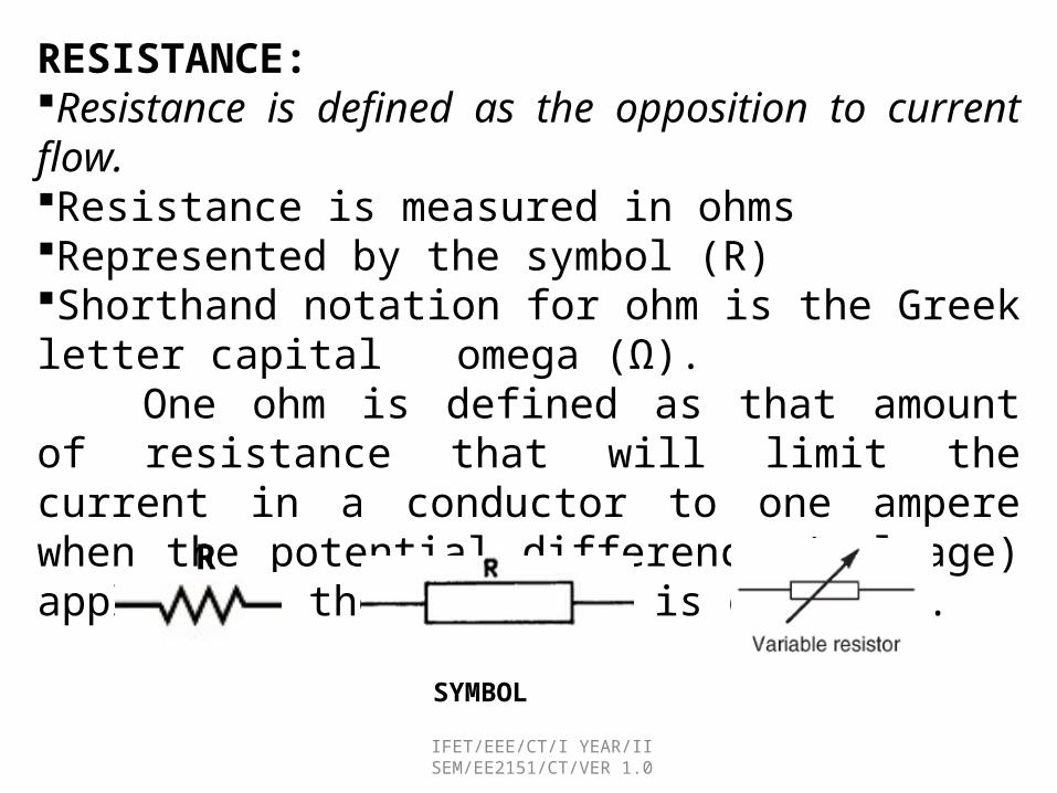
RESISTANCE:Resistance is defined as the opposition to current flow. Resistance is measured in ohmsRepresented by the symbol (R) Shorthand notation for ohm is the Greek letter capital omega (Ω).
One ohm is defined as that amount of resistance that will limit the current in a conductor to one ampere when the potential difference (voltage) applied to the conductor is one volt.
R
SYMBOL
IFET/EEE/CT/I YEAR/II SEM/EE2151/CT/VER 1.0

INDUCTANCE:•Inductance is defined as the ability of a coil to store energy, induce a voltage in itself, and oppose changes in current flowing through it. •The symbol used to indicate inductance is capital L. •The units of measurement is henries and is abbreviated by capital H.
•The negative sign indicates that voltage induced• opposes the change in current through the coil per unit time
SYMBOL
IFET/EEE/CT/I YEAR/II SEM/EE2151/CT/VER 1.0

CONDUCTANCE: Reciprocal of resistance is called conductance. Conductance can be defined as the ability to conduct current. Unit used to specify conductance is called "mho," which is ohm spelled backwards. Symbol for "mho“ is the Greek letter omega inverted . Symbol for conductance when used in a formula is G.
IFET/EEE/CT/I YEAR/II SEM/EE2151/CT/VER 1.0

CAPACITANCE:Capacitance is defined as the ability to store an electric charge and is symbolized by the capital letter C. Capacitance (C), measured in farads.The amount of charge (Q) that can be stored in a device or capacitor divided by the voltage (E) applied across the device or capacitor plates when the charge was stored.
C =
CAPACITOR ELECTROLYTIC CAPACITOR VARIABLE CAPACITOR
IFET/EEE/CT/I YEAR/II SEM/EE2151/CT/VER 1.0

IFET/EEE/CT/I YEAR/II SEM/EE2151/CT/VER 1.0

CIRCUIT ELEMENTS
• Active elements» It has ability to supply energy that
activate a circuit.
»Eg. Generators and Batteries
• Passive elements» if it absorbs energy»Eg. Resistors, Capacitors,Inductors.
IFET/EEE/CT/I YEAR/II SEM/EE2151/CT/VER 1.0

IFET/EEE/CT/I YEAR/II SEM/EE2151/CT/VER 1.0
Bilateral Element:
Conduction of current in both directions in an element (example: Resistance; Inductance; Capacitance) with same magnitude is termed as bilateral element.
Unilateral Element:Conduction of current in one direction is termed as unilateral (example: Diode, Transistor) element.

CLOSED CIRCUIT
IFET/EEE/CT/I YEAR/II SEM/EE2151/CT/VER 1.0

OPEN CIRCUIT
IFET/EEE/CT/I YEAR/II SEM/EE2151/CT/VER 1.0

SHORT CIRCUIT
IFET/EEE/CT/I YEAR/II SEM/EE2151/CT/VER 1.0

When resistors are connected ‘ end-to-end ’ so that the same current flows through them all they are said to be cascaded or connected in series . Such a circuit is shown in Fig. Note that, for the sake of simplicity, an ideal source of emf has been used (no internal resistance).
SERIES CIRCUIT
IFET/EEE/CT/I YEAR/II SEM/EE2151/CT/VER 1.0

IFET/EEE/CT/I YEAR/II SEM/EE2151/CT/VER 1.0
Series Circuit
Current is constant
Why? Only one path for the
current to take
1 2 3
1 2 3
1 2 3
V V V V
I I I I
R R R R
V I R

IFET/EEE/CT/I YEAR/II SEM/EE2151/CT/VER 1.0
Series Equivalent Circuit
1 1 2 2 3 3
1 2 3
1 2 3
1 2 3
1 2 3
V I R V I R V I R
R R R R
V V V V
V I R I R I R
V I R R R
V I R

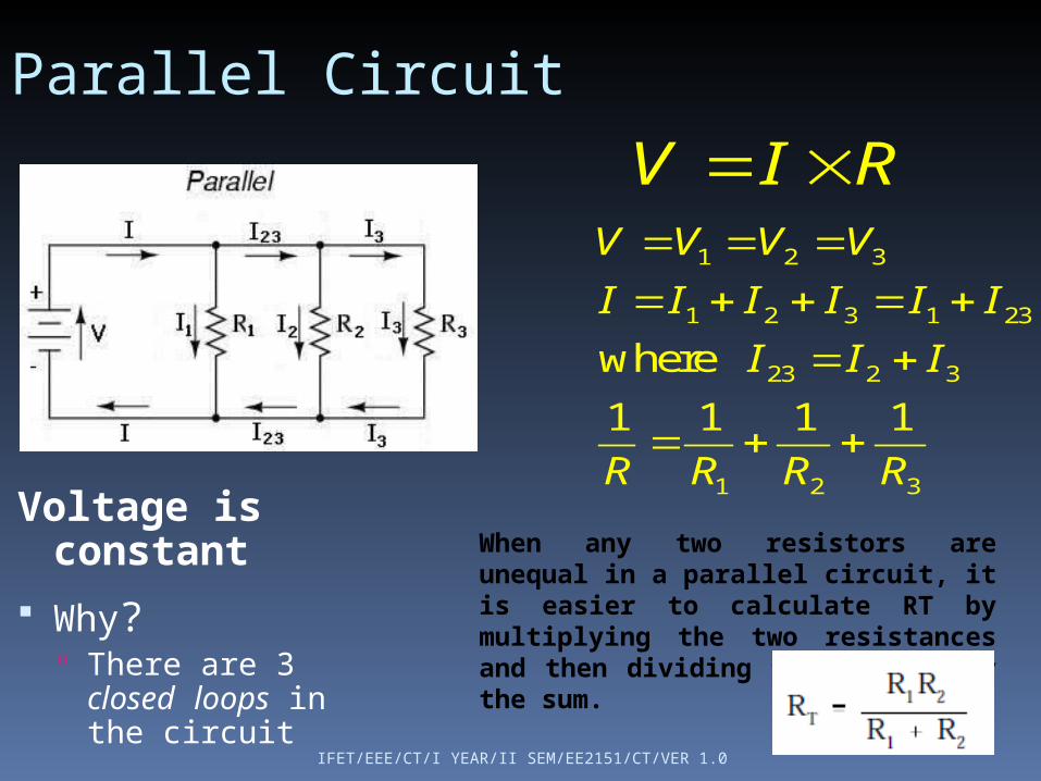
When resistors are joined ‘ side-by-side ’ so that their corresponding ends are connected together they are said to be connected in parallel . Using this form of connection means that there will be a number of paths through which the current can fl ow. Such a circuit consisting of three resistors is shown in Fig.
PARALLEL CIRCUIT
IFET/EEE/CT/I YEAR/II SEM/EE2151/CT/VER 1.0
IFET/EEE/CT/I YEAR/II SEM/EE2151/CT/VER 1.0
Parallel Circuit
Voltage is constant
Why? There are 3 closed loops in the circuit
1 2 3
1 2 3 1 23
23 2 3
1 2 3
where
1 1 1 1
V V V V
I I I I I I
I I I
R R R R
V I R
When any two resistors are unequal in a parallel circuit, it is easier to calculate RT by multiplying the two resistances and then dividing the product by the sum.

IFET/EEE/CT/I YEAR/II SEM/EE2151/CT/VER 1.0
Linear Circuit: Linear circuit is one whose parameters do not change with voltage or current.
Non-Linear Circuit: Non-linear system is that whose parameters change with voltage or current.
VI characteristics VI characteristics

IFET/EEE/CT/I YEAR/II SEM/EE2151/CT/VER 1.0
SIMPLE RESISTIVE NETWORK
Node- A node in an electric circuit is a point where two or more components are connected together. This point is usually marked with dark circle or dot. The circuit in fig. has nodes a, b, c, and g.

IFET/EEE/CT/I YEAR/II SEM/EE2151/CT/VER 1.0
Branch- A branch is a conducting path between two nodes in a circuit containing the electric elements. These elements could be sources, resistances, or other elements. Fig. shows that the circuit has six branches: three resistive branches (a-c, b-c, and b-g) and three branches containing voltage and current sources (a-, a-, and c-g). Loop- A loop is any closed path in an electric circuit i.e., a closed path or loop in a circuit is a contiguous sequence of branches which starting and end points for tracing the path are, in effect, the same node and touches no other node more than once. Fig. shows three loops or closed paths namely, a-b-g-a; b-c-g-b; and a-c-b-a. Further, it may be noted that the outside closed paths a-c-g-a and a-b-c-g-a are also form two loops. Mesh- A mesh is a special case of loop that does not have any other loops within it or in its interior. Fig. indicates that the first three loops (a-b-g-a; b-c-g-b; and a-c-b-a) just identified are also ‘meshes’ but other two loops (a-c-g-a and a-b-c-g- a)are not.

Independence voltage sourcesIndependent of the current thru the sources
Symbol for: (a) DC voltage source; (b) battery; (c) ac voltage source.
IFET/EEE/CT/I YEAR/II SEM/EE2151/CT/VER 1.0

Independence current sourcesIndependent of the voltage thru the sources
Symbol for an independent current source.
IFET/EEE/CT/I YEAR/II SEM/EE2151/CT/VER 1.0
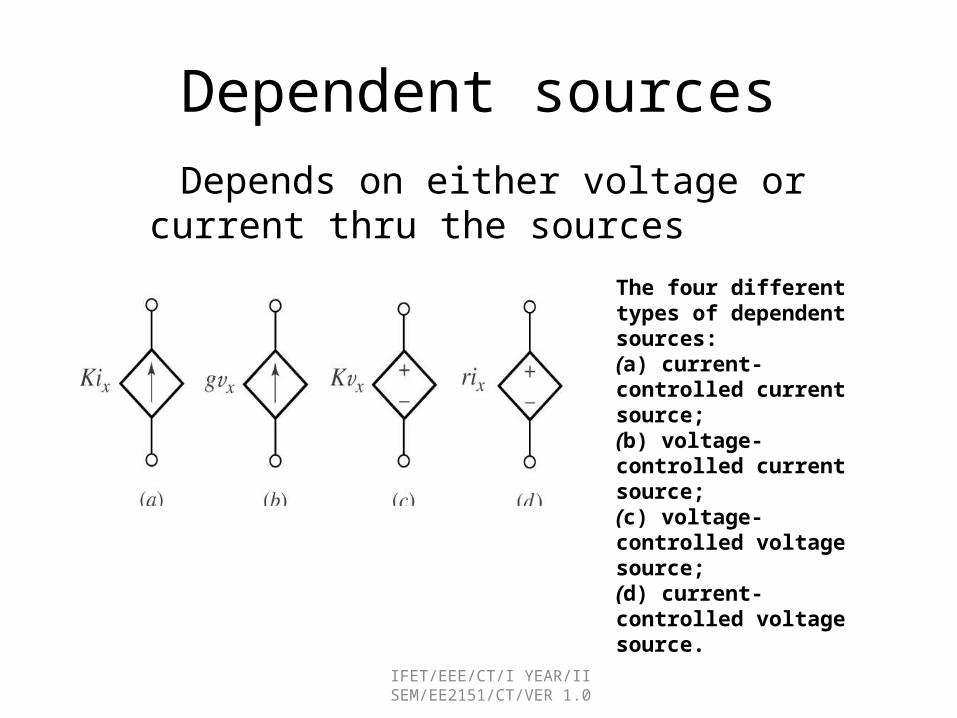
Dependent sources
The four different types of dependent sources:(a) current-controlled current source;(b) voltage-controlled current source;(c) voltage-controlled voltage source;(d) current-controlled voltage source.
Depends on either voltage or current thru the sources
IFET/EEE/CT/I YEAR/II SEM/EE2151/CT/VER 1.0

Ideal Voltage Sources: Series
• Ideal voltage sources connected in series add
IFET/EEE/CT/I YEAR/II SEM/EE2151/CT/VER 1.0

Ideal Voltage Sources: Parallel
• Ideal voltage sources cannot be connected in parallel• Recall: ideal voltage sources guarantee the voltage between two
terminals is at the specified potential (voltage)• Immovable object meets unstoppable force• In practice, the stronger source would win• Could easily cause component failure (smoke)• Ideal sources do not exist• Technically allowed if V1 = V2, but a bad idea
IFET/EEE/CT/I YEAR/II SEM/EE2151/CT/VER 1.0

Ideal Current Sources: Series
• Ideal current sources cannot be connected in series• Recall: ideal current sources guarantee the current flowing through
source is at specified value• Recall: the current entering a circuit element must equal the current
leaving a circuit element, Iin = Iout
• Could easily cause component failure (smoke)• Ideal sources do not exist• Technically allowed if if I1 = I2, but a bad idea
IFET/EEE/CT/I YEAR/II SEM/EE2151/CT/VER 1.0

Ideal Current Sources: Parallel
• Ideal current sources in parallel add
IFET/EEE/CT/I YEAR/II SEM/EE2151/CT/VER 1.0

OHM’S LAW
In 1827, George Simon Ohm discovered that there was a definite relationship between voltage, current, and resistance.
Ohm’s law states that the current I flowing in a circuit is directly proportional to the applied voltage V and inversely proportional to the resistance R, provided the temperature remains constant.
Prob:The current flowing through a resistor is 0.8 A when a p.d. of 20 V is applied. Determine the value of the resistance.
IFET/EEE/CT/I YEAR/II SEM/EE2151/CT/VER 1.0
George Simon Ohm German scientist 1787-1854

Ohm’s Law Triangle
V
I R)A,amperes(
R
VI
),ohms( I
VR
)V,volts( R I V
V
I R
V
I R
IFET/EEE/CT/I YEAR/II SEM/EE2151/CT/VER 1.0

Ohm’s Law continued
IFET/EEE/CT/I YEAR/II SEM/EE2151/CT/VER 1.0

Resistance
IFET/EEE/CT/I YEAR/II SEM/EE2151/CT/VER 1.0
IFET/EEE/CT/I YEAR/II SEM/EE2151/CT/VER 1.0

Direction of Voltage & Current on Resistors
+ -
Current will pass thru a resistance from higher voltageto the lower one.
- +or
IFET/EEE/CT/I YEAR/II SEM/EE2151/CT/VER 1.0

PROBLEM
IFET/EEE/CT/I YEAR/II SEM/EE2151/CT/VER 1.0

For the circuit shown in Fig. calculate (a) the circuit resistance, (b) the circuit current, (c) the p.d.developed across each resistor, and (d) the power dissipated by the complete circuit.
PROBLEM
IFET/EEE/CT/I YEAR/II SEM/EE2151/CT/VER 1.0
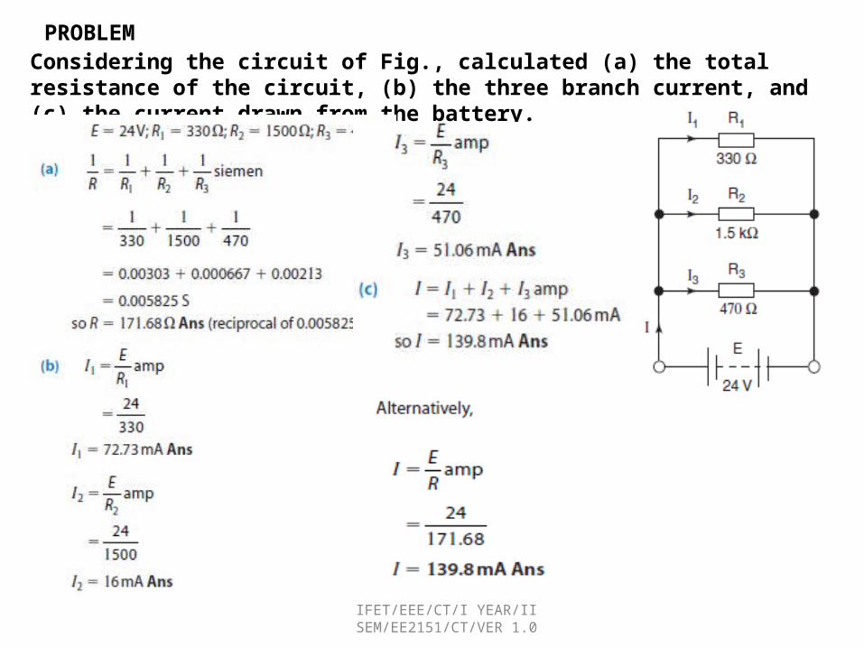
Considering the circuit of Fig., calculated (a) the total resistance of the circuit, (b) the three branch current, and (c) the current drawn from the battery.
PROBLEM
IFET/EEE/CT/I YEAR/II SEM/EE2151/CT/VER 1.0

PROBLEM
IFET/EEE/CT/I YEAR/II SEM/EE2151/CT/VER 1.0

Potential DividerWhen resistors are connected in series the p.d. developed across each resistor will be in direct proportion to its resistance value.
Applying the potential divider technique, the two p.d.s may be obtained by using the fact that the p.d. across a resistor is given by the ratio of its resistance value to the total resistance of the circuit.
This technique is not restricted to only two resistors in series, but may be applied to any number. For example, if there were three resistors in series, then the p.d. across each may be found
IFET/EEE/CT/I YEAR/II SEM/EE2151/CT/VER 1.0

Current DividerWhen resistors are connected in parallel the total circuit current divides between the alternative paths available.
I1=[24/12+24]*6=4A
I2=[12/12+24]*6=2A
=6A
The current divider theory is not limited to only two resistors in parallel. Any number can be accommodated. However, with three or more parallel resistors the current division method can be used. it is much easier for mistakes to be made. For this reason it is recommended that where more than two resistors exist in parallel the‘ p.d. method ’ is used.
IFET/EEE/CT/I YEAR/II SEM/EE2151/CT/VER 1.0

Kirchhoff ’ s Current LawStates that algebraic sum of the currents at any junction of a circuit is zero. Another, and perhaps simpler, way of stating this is to say that the sum of the currents arriving at a junction is equal to the sum of the currents leaving that junction.
where the symbol ∑ means ‘ the sum of ’ .
Fig illustrates a junction within a circuit with a number of currents arriving and leaving the junction. Applying Kirchhoff ’ s current law yields: where ‘+ ’ signs have been used to denote currents arriving and ‘_’ signs for currents leaving the junction.
IFET/EEE/CT/I YEAR/II SEM/EE2151/CT/VER 1.0
Gustav Kirchhoff1824-1887
German Physicist

Kirchhoff’s Current Law
Current into junction = Current leaving junction
1 2
0
in out
in out
I I I I
I I
The amount of current that enters a junction The amount of current that enters a junction is equivalent to the amount of current that is equivalent to the amount of current that leaves the junctionleaves the junction
Iin=Iout
Iin I1
I2
I2
I1
Iout
IFET/EEE/CT/I YEAR/II SEM/EE2151/CT/VER 1.0

Kirchhoff’s Laws
Determine the current I for the circuit shown in the figure below.
I + 4-(-3)-2 = 0
I = -5A
This indicates that the actual current for
I is flowing in the opposite direction.
We can consider the whole enclosed area as one “node”.
IFET/EEE/CT/I YEAR/II SEM/EE2151/CT/VER 1.0

PROBLEM:For the network shown in Fig. calculate the values of the marked currents.
Note: The minus sign in the last answer tells us that the current I5 is actually flowing away from the junction rather than towards it as shown.
IFET/EEE/CT/I YEAR/II SEM/EE2151/CT/VER 1.0

Kirchhoff ’ s Voltage Law
* The law states that in a closed circuit, the algebraic sum of all source voltages must be equal to the algebraic sum of all the voltage drops.
*Sum of all voltage rises and voltage drops in a circuit (a closed loop) equals zero
1 2 ...
in
in
V VoltageAcrossEachResistor
V V V
V
V1 V2
1 2
1 2 0
V V V
V V VNet Voltage for a circuit = 0
IFET/EEE/CT/I YEAR/II SEM/EE2151/CT/VER 1.0
Gustav Kirchhoff1824-1887
German Physicist

Kirchhoff’s voltage Law• Applying the KVL equation for the circuit of the figure below.
va-v1-vb-v2-v3 = 0
V1 = IR1 v2 = IR2 v3 = IR3
va-vb = I(R1 + R2 + R3)
321 RRR
vvI ba
IFET/EEE/CT/I YEAR/II SEM/EE2151/CT/VER 1.0


![Circuit training ppt [autosaved]](https://img.dokumen.tips/doc/110x75/58ee5c2e1a28ab404b8b4723/circuit-training-ppt-autosaved.jpg)