Embed Size (px)
Citation preview

8/8/2019 26409484 Circuit Theory
http://slidepdf.com/reader/full/26409484-circuit-theory 1/18
Circuit Theory
1. Basic Circuit
2. Circuit Network With LoadResistance
3. Circuit Analysis/Electrical Network
4. Circuit With Inductor(L)
5. Circuit With Capacitor(C)
6. Circuit With Reactance(X) andImpedance(Z)

8/8/2019 26409484 Circuit Theory
http://slidepdf.com/reader/full/26409484-circuit-theory 2/18
1. Basic Theory
1. Draw the Basic Circuit
2. Unit and Term-
1. Ampere (A)-electrical current
2. Volt (V)-different potential.
3. Ohm(Ω)-resistance
4. Coulomb (Q)-electrical charge
5. E.m.f.- Electromotive force
3. Part of Basic Circuit (next page)
Figure 3: BasicCircuit
At least 4 part:1.Source of emf
2.Conductor3.A load4.Switch (control)

8/8/2019 26409484 Circuit Theory
http://slidepdf.com/reader/full/26409484-circuit-theory 3/18
Symbol Symbol
Resistor
Variable Resistor Lamp
Cell Watt meter
Inductor Amp meter
Capacitor Volt meter
VV
AA
ww
Wire no
connected
Wire
connected
Node / Junction

8/8/2019 26409484 Circuit Theory
http://slidepdf.com/reader/full/26409484-circuit-theory 4/18
2. Circuit Network With LoadResistance(R)
• Connection of resistors1. Series-
• R total=R1+R2+Rn
• I total=I (R1) = I (R2) = I (Rn)
• E=V(R1) + V (R2) +V(Rn)• Voltage drop depend on resistor value
1. Parallel-• 1/R total=1/R1+1/R2+1/Rn
• I total=I (R1) + I (R2) + I (Rn)
• E=V(R1) = V (R2) = V(Rn)

8/8/2019 26409484 Circuit Theory
http://slidepdf.com/reader/full/26409484-circuit-theory 5/18
3. Circuit Analysis/ElectricalNetwork
1. Ohm’s law
2. Kirchhoff’s Current Laws (KCL)
3. Kirchhoff’s Voltage Laws (KVL)
4. Thevenin’s Theorem
5. Maximum Power Transfer
6. Wye-Delta Transformations
8/8/2019 26409484 Circuit Theory
http://slidepdf.com/reader/full/26409484-circuit-theory 6/18
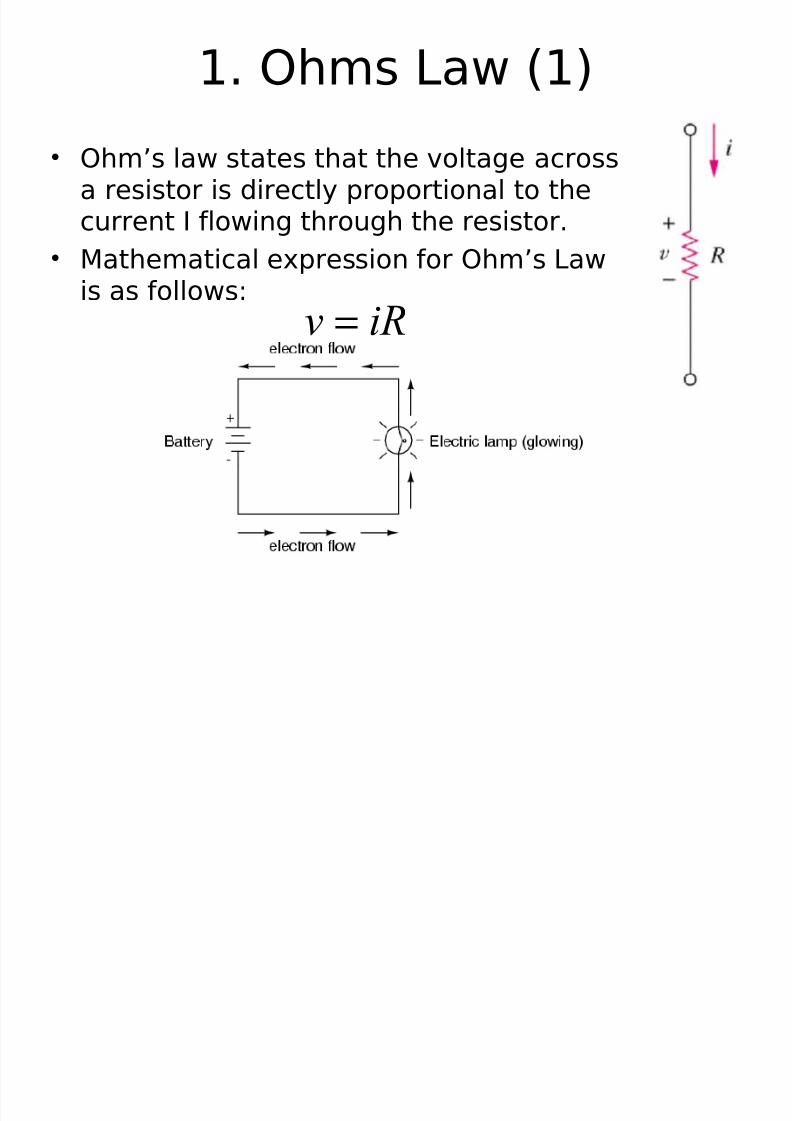
1. Ohms Law (1)
• Ohm’s law states that the voltage acrossa resistor is directly proportional to thecurrent I flowing through the resistor.
• Mathematical expression for Ohm’s Lawis as follows:
iRv =

8/8/2019 26409484 Circuit Theory
http://slidepdf.com/reader/full/26409484-circuit-theory 7/18
V
I R
VI R
V
I R
Example

8/8/2019 26409484 Circuit Theory
http://slidepdf.com/reader/full/26409484-circuit-theory 8/18
Nodes, Branches and Loops
• A branch represents a single elementsuch as a voltage source or aresistor.
• A node is the point of connectionbetween two or more branches.
• A loop is any closed path in a circuit.

8/8/2019 26409484 Circuit Theory
http://slidepdf.com/reader/full/26409484-circuit-theory 9/18
Nodes, Branches and Loops
Example
How many branches, nodes and loops are there?
Original circuit
Equivalent circuit

8/8/2019 26409484 Circuit Theory
http://slidepdf.com/reader/full/26409484-circuit-theory 10/18
3. Kirchhoff’s Current Laws (KCL)
•states that :
–the algebraic sum of currents entering a node is zero. or
– The total currents enter a node=The current exit a node
0
1
=∑=
N
n
ni
Mathematically,
itotal =i1+i3+i4=i5+i2…
….(ii)
itotal =i1+i3+i2+i4+i5=
0…(i)

8/8/2019 26409484 Circuit Theory
http://slidepdf.com/reader/full/26409484-circuit-theory 11/18
Example: Give theexpression of itotal
itotal =i1=i2+i3…….(ii)
itotal =i1-i3+i2=0…(i)Answer:
8/8/2019 26409484 Circuit Theory
http://slidepdf.com/reader/full/26409484-circuit-theory 12/18
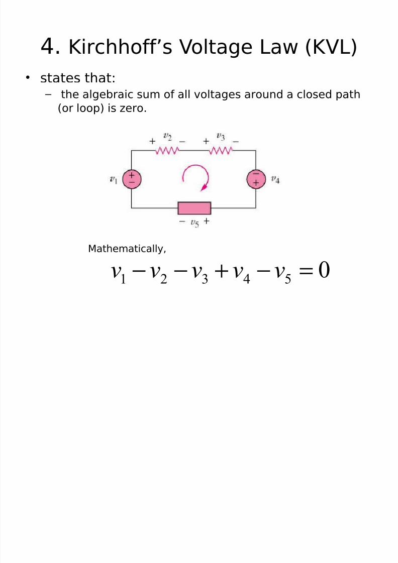
4. Kirchhoff’s Voltage Law (KVL)
• states that: – the algebraic sum of all voltages around a closed path
(or loop) is zero.
Mathematically,
054321 =−+−−vvvvv

8/8/2019 26409484 Circuit Theory
http://slidepdf.com/reader/full/26409484-circuit-theory 13/18
4. Kirchhoff’s Voltage Law
(KVL)Example
• Applying the KVL equation for the circuit of thefigure below.
v a-v 1-v b-v 2-v 3 = 0
V 1 = IR1 v 2 = IR2 v 3 = IR3
⇒
v a-v b = I(R1 + R2 + R3 )
321 R R R
vv I
ba
++−
=

8/8/2019 26409484 Circuit Theory
http://slidepdf.com/reader/full/26409484-circuit-theory 14/18
5. Thevenin’s Theorem
It states that a linear two-terminalcircuit (Fig. a) can be replaced by anequivalent circuit (Fig. b) consisting of a voltage source V
TH in series with a
resistor RTH
,
where
• VTH is the open-circuit voltage at the
terminals.
• RTH is the input or equivalent resistance atthe terminals when the independentsources are turned off.

8/8/2019 26409484 Circuit Theory
http://slidepdf.com/reader/full/26409484-circuit-theory 15/18

8/8/2019 26409484 Circuit Theory
http://slidepdf.com/reader/full/26409484-circuit-theory 16/18
Step of Thevenin’s Theorem
• Step 1:
– Remove resistor(RL) and mark terminal a-b
• Step 2:
–
Find R TH
by close voltage supply and open currentsupply
• Step 3:
– Find V Th at terminal a-b
•
Step 4: – Draw equivalent circuit for Thevenin and put RL

8/8/2019 26409484 Circuit Theory
http://slidepdf.com/reader/full/26409484-circuit-theory 17/18
6. Maximum Power Transfer
L
Th
TH L
R
V P R R
4
2
max =⇒=
If the entire circuit is replaced byits Thevenin equivalent except forthe load, the power delivered tothe load is:
The power transfer profile withdifferent RL
For maximum power dissipated
in RL, Pmax , for a given R TH ,and V TH ,
L
LTh
Th
LR
R R
V Ri P
22
+==

8/8/2019 26409484 Circuit Theory
http://slidepdf.com/reader/full/26409484-circuit-theory 18/18
7. Wye-Delta Transformations
)(1
cba
cb
R R R
R R R
++=
)(2
cba
ac
R R R
R R
R ++=
)(3
cba
ba
R R R
R R R
++=
1
133221
R
R R R R R R R
a
++=
2
133221
R
R R R R R R
Rb
++=
3
133221
R
R R R R R R R
c
++=
Delta -> Star Star -> Delta