Embed Size (px)
Citation preview
CIMON PLC Loader Program
1
1 Table of Contents ……………………………………………………………………………………………………… 1
2 Preface ……………………………….…………………………………………………………………………… 2
2.1 Requirements for Installation …………………………………………………………………………… 2
2.2 Installation Method ………………………………………………………………………………………… 2
3 CICON Components ……………………………………………………………………………………… 4
3.1 Screen Configuration………………………………………………………………………………………… 4
3.2 Menu Composition ………………………………………………………………………………………… 6
3.3 Set CICON Environment ……………………………………………………………………………… 10
4 Programming (Single Programs)……………………………………………………………………… 12
4.1 Contents of Example Programs …………………………………………………………………………… 12
4.2 Creating Project and Program …………………………………………………………………… 12
4.3 Writing Scan Program …………………………………………………………………………… 13
4.4 Communication Setting ……………………………………………………………………………………… 19
4.5 Compile/Link, Download, Monitor ……………………………………………………………… 21
5 Project Management ………………………………………………………………………………………… 24
5.1 Types of Scan Program ………………………………………………………………………… 24
5.2 Scan Program ………………………………………………………………………………… 25
5.3 Sub-routine Program …………………………………………………………………………… 25
5.4 Initialization Program (Cold) …………………………………………………………………… 26
5.5 Initialization Program (Hot) ……………………………………………………………………… 26
5.6 Regular Interval Interrupt Program …………………………………………………………………… 27
6 Programming (Multiple Programs) ……………………………………………………………………… 28
6.1 Contents of Example Programs …………………………………………………………………………… 28
6.2 Adding/Deleting Program ………………………………………………………………………… 28
6.3 Writing/Managing Program ………………………………………………………………………… 29
6.4 Parameter Setting ………………………………………………………………………………… 34
6.5 I/O Reservation ………………………………………………………………………………………… 38
7 PLC Control ……………………………………………………………………………………………… 40
7.1 PLC Operation Control ………………………………………………………………………………… 40
7.2 RAM and ROM Operation Mode ………………………………………………………………………… 41
8 Special Card Setting ……………………………………………………………………………………… 42
9 Special Program ………………………………………………………………………………………… 70
10 Appendix …………………………………………………………………………………………………… 115
10.1 Shortcut Key …………………………………………………………………………………… 115
10.2 Loader Cabling Diagram …………………………………………………………………… 116
CIMON PLC Loader Program
2
2 Preface 2.1 Requirements for Installation
Recommended hardware specification for CICON installation
PC
Pentium 133Mhz CPU or faster, 64MB RAM or more including the expansion memory.
Serial port
More than 1 serial port is required to utilize CICON functions to the maximum extent, and
establish communication using PLC loader port RS232C/422/485.
Ethernet
Ethernet port is required to establish Ethernet connection between CICON and PLC.
Hard disk
At least 13MB free hard space is required to install all CICON installation files and use
CICION properly.
Mouse
To fully use CICION function, a Korea/English Windows compatible mouse is needed that can
be connected to the PC.
OS
Windows 98SE/2000/XP Korean version is recommended.
2.2 Installation Method
Download
Connect to our web site and download the latest CICION program.
(Visit “Customer Support” -> “General Download.”)
Installation
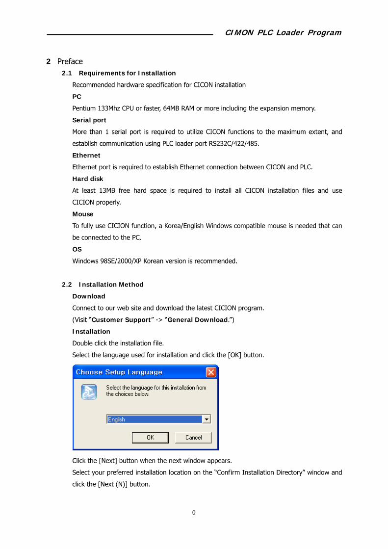
Double click the installation file.
Select the language used for installation and click the [OK] button.
Click the [Next] button when the next window appears.
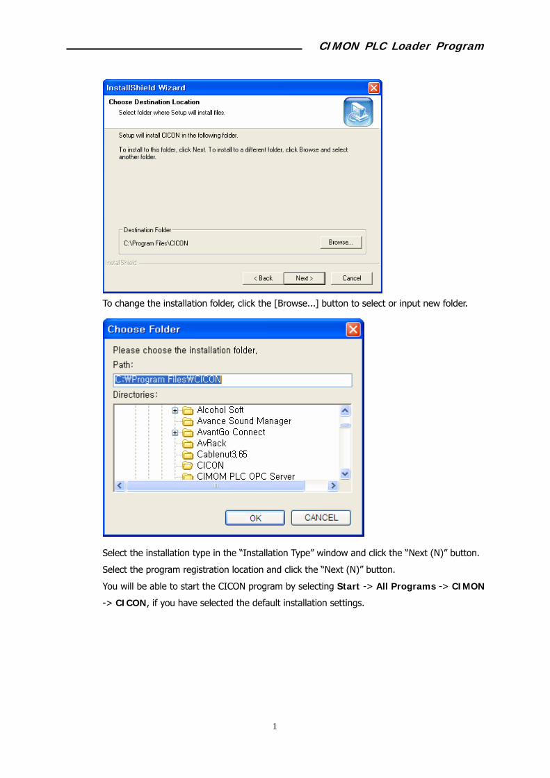
Select your preferred installation location on the “Confirm Installation Directory” window and
click the [Next (N)] button.
CIMON PLC Loader Program
3
To change the installation folder, click the [Browse...] button to select or input new folder.
Select the installation type in the “Installation Type” window and click the “Next (N)” button.
Select the program registration location and click the “Next (N)” button.
You will be able to start the CICON program by selecting Start -> All Programs -> CIMON
-> CICON, if you have selected the default installation settings.
CIMON PLC Loader Program
4
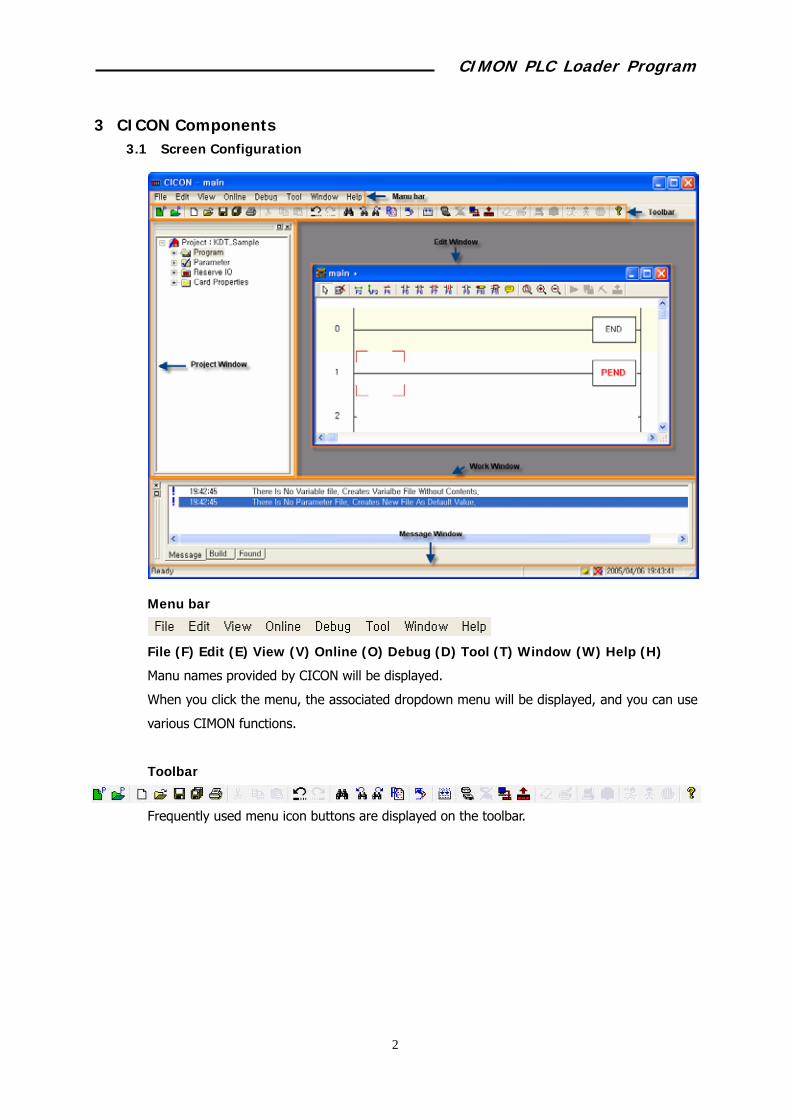
3 CICON Components 3.1 Screen Configuration
Menu bar
File (F) Edit (E) View (V) Online (O) Debug (D) Tool (T) Window (W) Help (H)
Manu names provided by CICON will be displayed.
When you click the menu, the associated dropdown menu will be displayed, and you can use
various CIMON functions.
Toolbar
Frequently used menu icon buttons are displayed on the toolbar.

CIMON PLC Loader Program
5
Project window
You can check the name of the project that you have opened.
In the project, you can find programs registered in the project, and find and modify PLC
parameters, and check the status of modules mounted online.
Work window
In this window, your working details will be displayed.
Edit window
There are several types of edit window such as Edit Variable, Edit LD, and Edit Parameter
window. You can use these windows to edit program, parameter, and configuration
respectively.
Message window

CIMON PLC Loader Program
6
Message window will display the result of compilation, download, and search.
Message list will be displayed. To check the scrolled-up message, move the slide button on
the right side.
CIMON PLC Loader Program
7
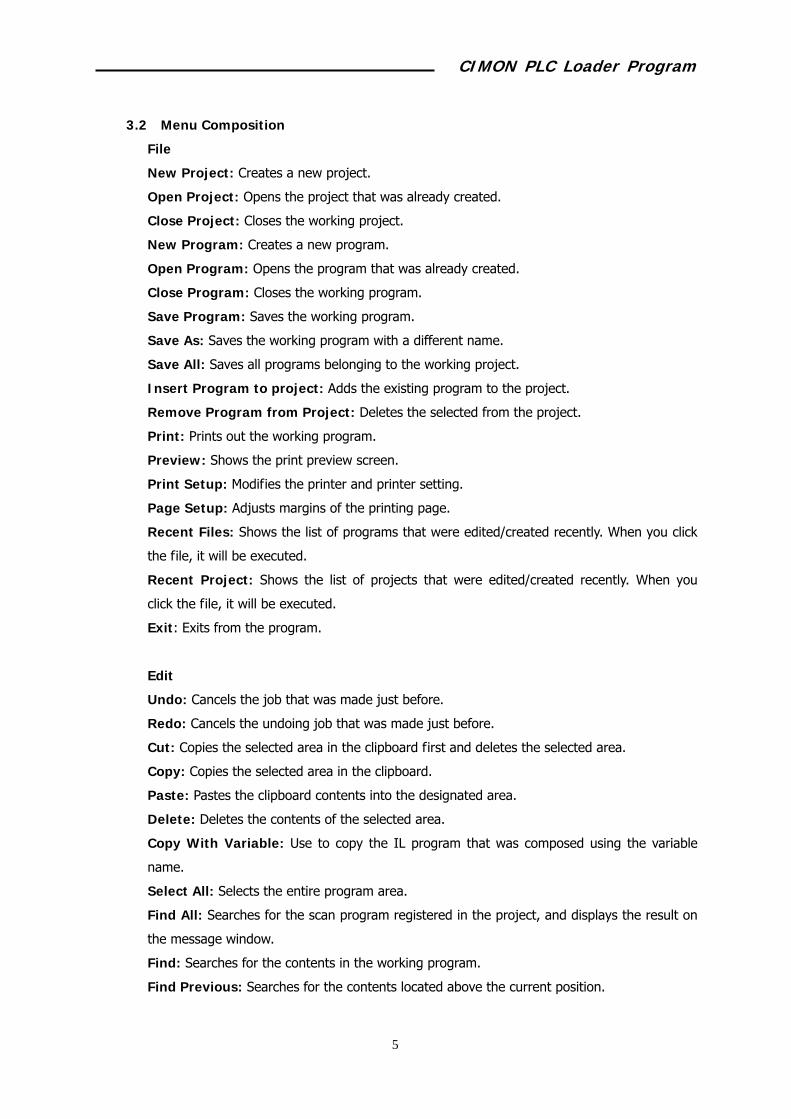
3.2 Menu Composition
File
New Project: Creates a new project.
Open Project: Opens the project that was already created.
Close Project: Closes the working project.
New Program: Creates a new program.
Open Program: Opens the program that was already created.
Close Program: Closes the working program.
Save Program: Saves the working program.
Save As: Saves the working program with a different name.
Save All: Saves all programs belonging to the working project.
Insert Program to project: Adds the existing program to the project.
Remove Program from Project: Deletes the selected from the project.
Print: Prints out the working program.
Preview: Shows the print preview screen.
Print Setup: Modifies the printer and printer setting.
Page Setup: Adjusts margins of the printing page.
Recent Files: Shows the list of programs that were edited/created recently. When you click
the file, it will be executed.
Recent Project: Shows the list of projects that were edited/created recently. When you
click the file, it will be executed.
Exit: Exits from the program.
Edit
Undo: Cancels the job that was made just before.
Redo: Cancels the undoing job that was made just before.
Cut: Copies the selected area in the clipboard first and deletes the selected area.
Copy: Copies the selected area in the clipboard.
Paste: Pastes the clipboard contents into the designated area.
Delete: Deletes the contents of the selected area.
Copy With Variable: Use to copy the IL program that was composed using the variable
name.
Select All: Selects the entire program area.
Find All: Searches for the scan program registered in the project, and displays the result on
the message window.
Find: Searches for the contents in the working program.
Find Previous: Searches for the contents located above the current position.
CIMON PLC Loader Program
8
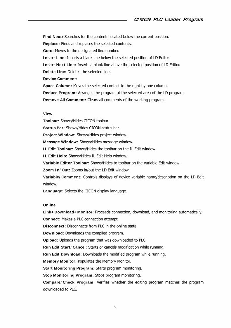
Find Next: Searches for the contents located below the current position.
Replace: Finds and replaces the selected contents.
Goto: Moves to the designated line number.
Insert Line: Inserts a blank line below the selected position of LD Editor.
Insert Next Line: Inserts a blank line above the selected position of LD Editor.
Delete Line: Deletes the selected line.
Device Comment:
Space Column: Moves the selected contact to the right by one column.
Reduce Program: Arranges the program at the selected area of the LD program.
Remove All Comment: Clears all comments of the working program.
View
Toolbar: Shows/Hides CICON toolbar.
Status Bar: Shows/Hides CICON status bar.
Project Window: Shows/Hides project window.
Message Window: Shows/Hides message window.
IL Edit Toolbar: Shows/Hides the toolbar on the IL Edit window.
IL Edit Help: Shows/Hides IL Edit Help window.
Variable Editor Toolbar: Shows/Hides to toolbar on the Variable Edit window.
Zoom In/Out: Zooms in/out the LD Edit window.
Variable/Comment: Controls displays of device variable name/description on the LD Edit
window.
Language: Selects the CICON display language.
Online
Link+Download+Monitor: Proceeds connection, download, and monitoring automatically.
Connect: Makes a PLC connection attempt.
Disconnect: Disconnects from PLC in the online state.
Download: Downloads the compiled program.
Upload: Uploads the program that was downloaded to PLC.
Run Edit Start/Cancel: Starts or cancels modification while running.
Run Edit Download: Downloads the modified program while running.
Memory Monitor: Populates the Memory Monitor.
Start Monitoring Program: Starts program monitoring.
Stop Monitoring Program: Stops program monitoring.
Compare/Check Program: Verifies whether the editing program matches the program
downloaded to PLC.

CIMON PLC Loader Program
9
Erase Program: Deletes the program saved in the PLC RAM.
Flash Memory: Changes the mode of PLC RAM/ROM operation, copies the RAM program to
the ROM, or deletes the ROM.
Change Mode: Runs, stops, pauses PLC when the PLC mode switch is in the remote mode.
BP Latch: Saves the BP latch area in the data file, or downloads the file data into the BP.
Enable/Disable Module: Prevents I/O mounting/dismounting error of the specified slot.
PLC Password: Sets the connection password for PLC.
Get Card Property: Reads the information on the module mounted on PLC and displays it
on the Project Window.
PLC Status: Checks the PLC CPU state and sets the time.
Debug
Run Debugging/Continue: Starts debugging.
Stop Debugging: Stops debugging.
Run for Scans..: Maintains operation as long as the scanned area.
Asingn/Release Break Point: Sets or clears the break point.
Release All Break Points: Clears all break point settings.
Enable Forced Input/Output: Allows forced I/O.
Forced Input/Output Setup: Sets forced I/O.
Tools
Compile: Compiles the working file.
Line: Links the compiled file.
Compile+Link: Complies and links sequentially.
Compile+All Link: Compiles and links the entire project.
IL-LD Conversion: Converts the editing program to IL or LD.
Device Table: Displays the devices used in the project.
PLC Parameter: Opens the PLC Parameter Setting window.
Release I/O: Opens the I/O Reservation Setting window.
Variable Manager: Starts Variable Manager.
Optional Module Setup: Opens the Special Card Setting window.
Position Module: Opens the Position Setting Module window.
Device Trend: Opens Device Trend.
CICON Option: Performs settings related with CICON operation.
Connection Setup: Sets communication for connection to PLC.
Windows

CIMON PLC Loader Program
10
Next Window: Creates the same window with the working window.
Cascade type: Arranges the editing windows with a cascading layout.
Tile type: Arranges the editing windows with a tiling layout.
Arrange Icons: Arranges the minimized windows under the working window.
Help
Help: Opens the help text on CICON.
About CICON…: Displays the CICON information like the version number.

CIMON PLC Loader Program
11
3.3 CICON Option
Open last project automatically
The project that was opened last will be automatically opened when starting CICON.
Compile defore download
If the downloading program was modified, it will be automatically compiled.
Return arrow after symbol
Restores the mouse cursor to the “Selected” status entering the symbol.
Device command dialog in LD
When this option is selected, the Device Description Input window will be automatically
populated if the device is used that is not registered in the variable table of LD program.
Do not download variables
Variables are excluded at the time of compilation. The variable table will not be saved in PLC.
Do not download commends in source
Comments included in the program will be excluded at the time of compilation. The comment
section will be displayed as a blank when uploading.
Use auto. save
Automatically saves the project at the specified time period.
Location of project folder
Specifies the default folder for project creation.
CIMON PLC Loader Program
12
4 Programming (Single Programs) 4.1 Contents of Example Programs
When the input switch (X0000) is pressed, the lamp (Y0010) flashes. (Turning on and off are
repeated.)
If the switch X0000 is pressed while the lamp is on, the lamp will be turned off. On the
contrary, the lamp will be turned on if the switch X0000 is pressed while the lamp is turned
off.
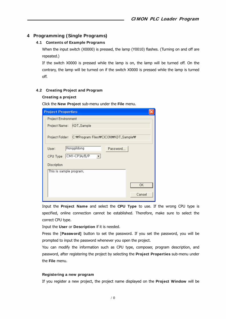
4.2 Creating Project and Program
Creating a project
Click the New Project sub-menu under the File menu.
Input the Project Name and select the CPU Type to use. If the wrong CPU type is
specified, online connection cannot be established. Therefore, make sure to select the
correct CPU type.
Input the User or Description if it is needed.
Press the [Password] button to set the password. If you set the password, you will be
prompted to input the password whenever you open the project.
You can modify the information such as CPU type, composer, program description, and
password, after registering the project by selecting the Project Properties sub-menu under
the File menu.
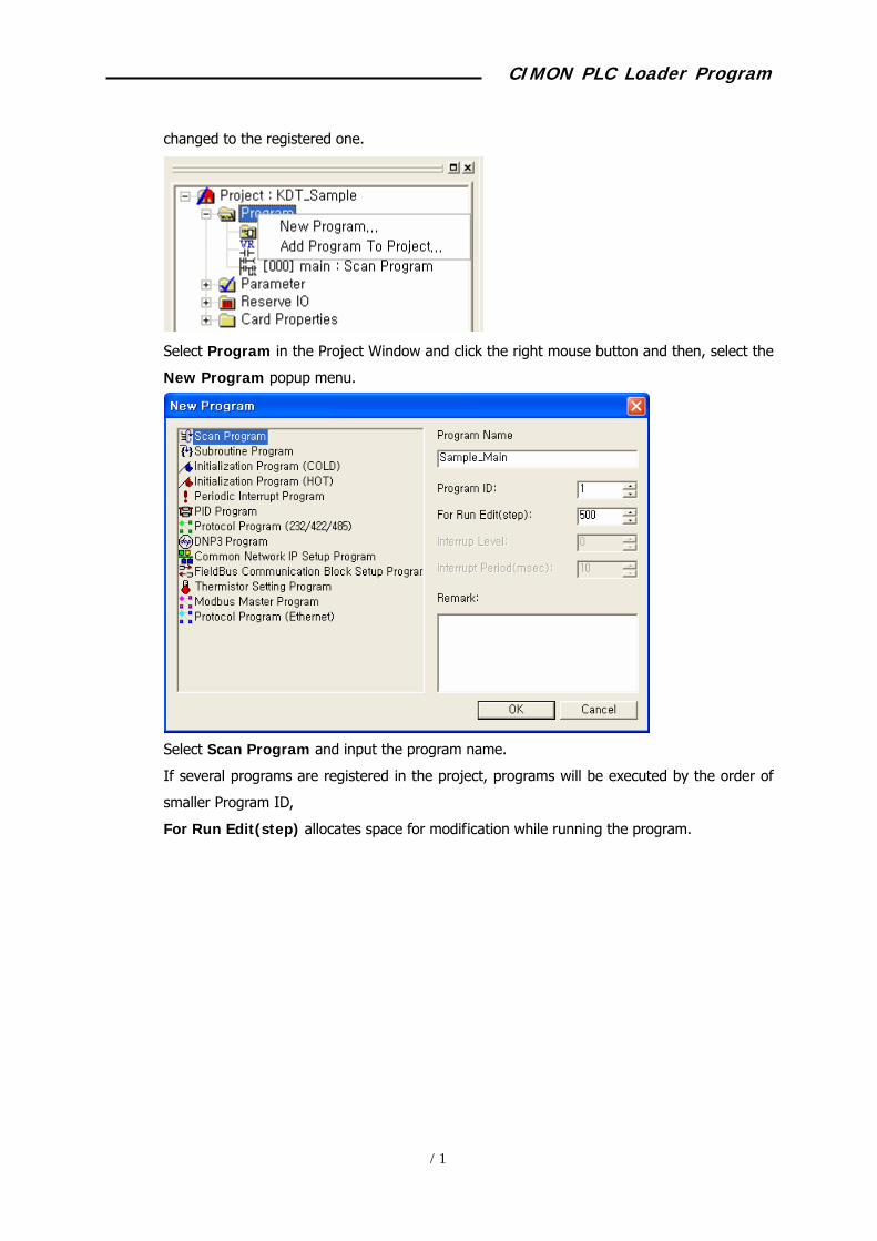
Registering a new program
If you register a new project, the project name displayed on the Project Window will be
CIMON PLC Loader Program
13
changed to the registered one.
Select Program in the Project Window and click the right mouse button and then, select the
New Program popup menu.
Select Scan Program and input the program name.
If several programs are registered in the project, programs will be executed by the order of
smaller Program ID,
For Run Edit(step) allocates space for modification while running the program.

CIMON PLC Loader Program
14
4.3 Writing Scan Program
Description of the menu bar
Select: Selects the intended contact or command in the LD program.
Delete: Deletes the selected contact or command.
Horizontal line: Draws a horizontal line at the selected position.
Vertical line: Draws a vertical line at the selected position.
Not: Inverts the result of the previous paragraph.
Contact a: Inserts a contact “a” (On if the device value is on.)
Contact b: Inserts a contact “b” (On if the device value is off.)
Rising pulse contact: Inserts a contact that is turned on during scanning, if the status
of the specified device is changed from Off to On.
Declining pulse contact: Inserts a contact that is turned on during scanning, if the status of the specified device is changed from On to Off.
Coil: Inputs a coil.
Command: Populates the command input window.
Counter command: Populates the counter command input window.
Comment: Populates the command input window.

CIMON PLC Loader Program
15
Original size: Restores the original size of the LD Edit window.
Zoom in: Zooms in the LD Edit window.
Zoom out: Zooms out the LD Edit window.
Start/Stop monitoring: Starts or stops program monitoring.
Convert data: Changes the value to decimal or hexadecimal value that is displayed
when monitoring the LD program.
Start/Stop editing in running: Starts or stops modification while the program is
running.
Download Edited Program in Running: Downloads the modified program while
running.

CIMON PLC Loader Program
16
Steps of writing a program
Writes a sequence program in the registered scan program using the LD editing tool.
Inserts a line to input the program using the [Ctrl + L] key.
Click the button in the toolbar to show the Rising Pulse Input window. Input “X0000.”
Click the [Select Variable] button to use the device register in the variable table.
CIMON PLC Loader Program
17
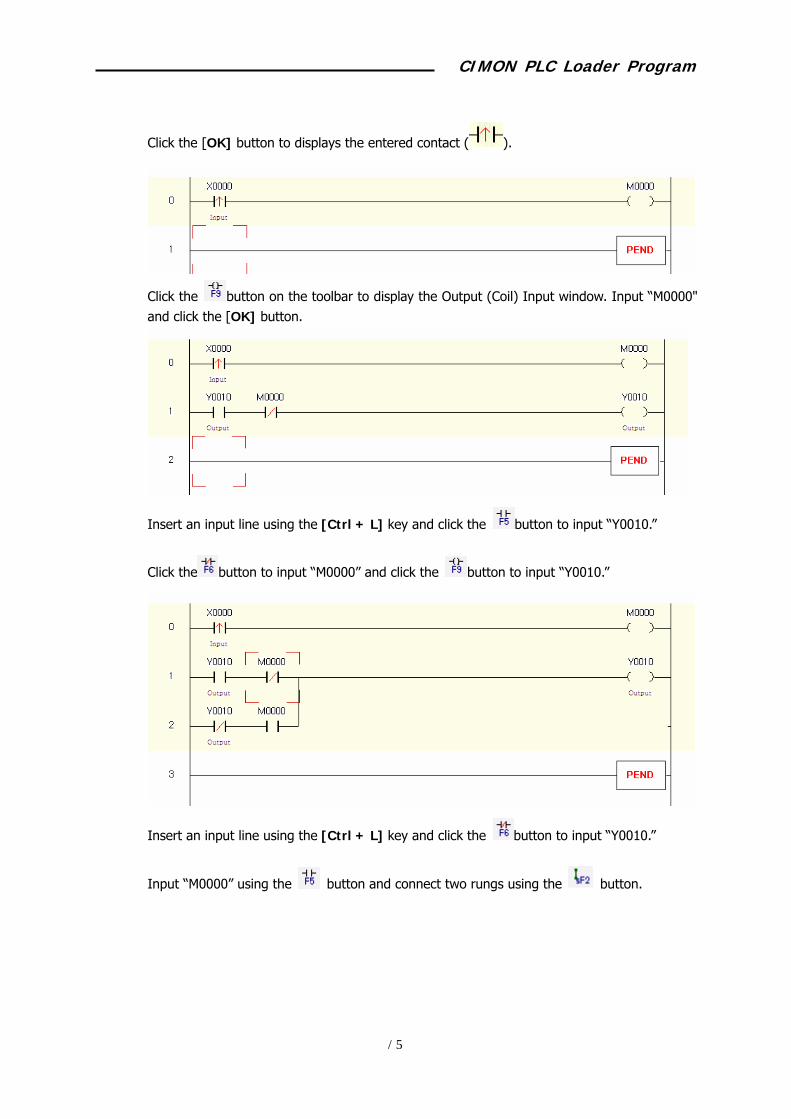
Click the [OK] button to displays the entered contact ( ).
Click the button on the toolbar to display the Output (Coil) Input window. Input “M0000" and click the [OK] button.
Insert an input line using the [Ctrl + L] key and click the button to input “Y0010.”
Click the button to input “M0000” and click the button to input “Y0010.”
Insert an input line using the [Ctrl + L] key and click the button to input “Y0010.”
Input “M0000” using the button and connect two rungs using the button.

CIMON PLC Loader Program
18
Insert an input line using the [Ctrl + L] key and click the button to input the END command.
Click File -> Save Program menu to save the entered program.
Entering a variable table
Double click the Variable Table in the project window to display the variable table.
Click the [Add...] button to display the variable input window.
CIMON PLC Loader Program
19
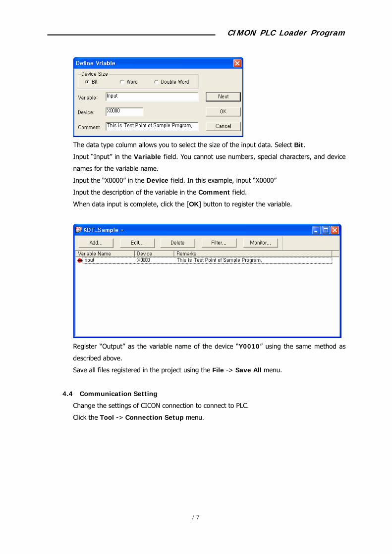
The data type column allows you to select the size of the input data. Select Bit.
Input “Input” in the Variable field. You cannot use numbers, special characters, and device
names for the variable name.
Input the “X0000” in the Device field. In this example, input “X0000”
Input the description of the variable in the Comment field.
When data input is complete, click the [OK] button to register the variable.
Register “Output” as the variable name of the device “Y0010” using the same method as
described above.
Save all files registered in the project using the File -> Save All menu.
4.4 Communication Setting
Change the settings of CICON connection to connect to PLC.
Click the Tool -> Connection Setup menu.

CIMON PLC Loader Program
20
When connecting directly to PLC through the PC COM port, select RS232 and modify the
items in the Communication Setting column.
The communication port means the one in the PC that the communication cable is connected.
The communication speed is fixed to 38,400bps when connected to the CPU loader port.
However, if connected to the loader through the communication module, it should match with
the settings of the communication module.
When connected to PLC through the PC COM port using the telephone modem, select Dial-
Up Modem and modify the Communication Setting column.
Input the phone number of the PLC connected party. Then, input the command to initialize
the modem connected to the PC.
CIMON PLC Loader Program
21
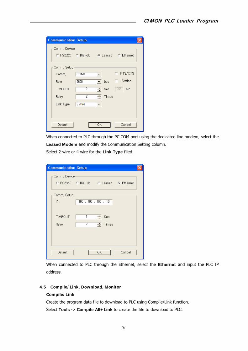
When connected to PLC through the PC COM port using the dedicated line modem, select the
Leased Modem and modify the Communication Setting column.
Select 2-wire or 4-wire for the Link Type filed.
When connected to PLC through the Ethernet, select the Ethernet and input the PLC IP
address.
4.5 Compile/Link, Download, Monitor
Compile/Link
Create the program data file to download to PLC using Compile/Link function.
Select Tools -> Compile All+Link to create the file to download to PLC.
CIMON PLC Loader Program
22
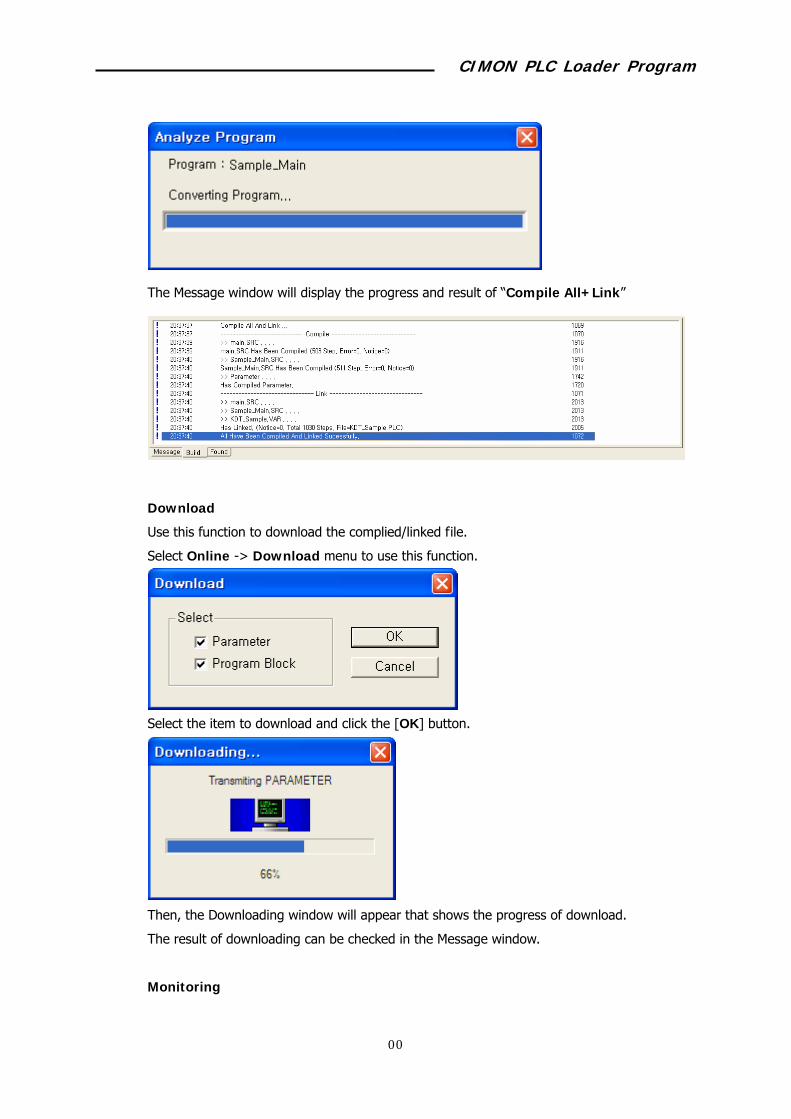
The Message window will display the progress and result of “Compile All+Link”
Download
Use this function to download the complied/linked file.
Select Online -> Download menu to use this function.
Select the item to download and click the [OK] button.
Then, the Downloading window will appear that shows the progress of download.
The result of downloading can be checked in the Message window.
Monitoring
CIMON PLC Loader Program
23
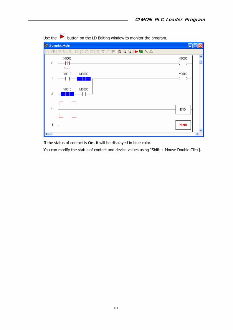
Use the button on the LD Editing window to monitor the program.
If the status of contact is On, it will be displayed in blue color.
You can modify the status of contact and device values using “Shift + Mouse Double Click].

CIMON PLC Loader Program
24
5 Project Management 5.1 Program Types
Select File -> New Program menu to create a new program.
Scan Program
Program that processes the signal repeated regularly at every scan.
Sub-routine Program
Program composed of sub-routines that are called by “ECALL” command in the scan program.
Initialization Program (Cold)
Program that is started when the power is supplied or the mode is changed to the Run mode.
It also sets the initialization data or initializes the peripheral or special module.
Initialization Program (Hot)
This program is executed if the power fails temporarily, and the hot start function is used,
and it is within the setting time. The initialization program (hot) is executed while keeping
previous values and the scan program is executed.
Periodic Interrupt Program
Program that is executed at a regular interval.
CIMON PLC Loader Program
25
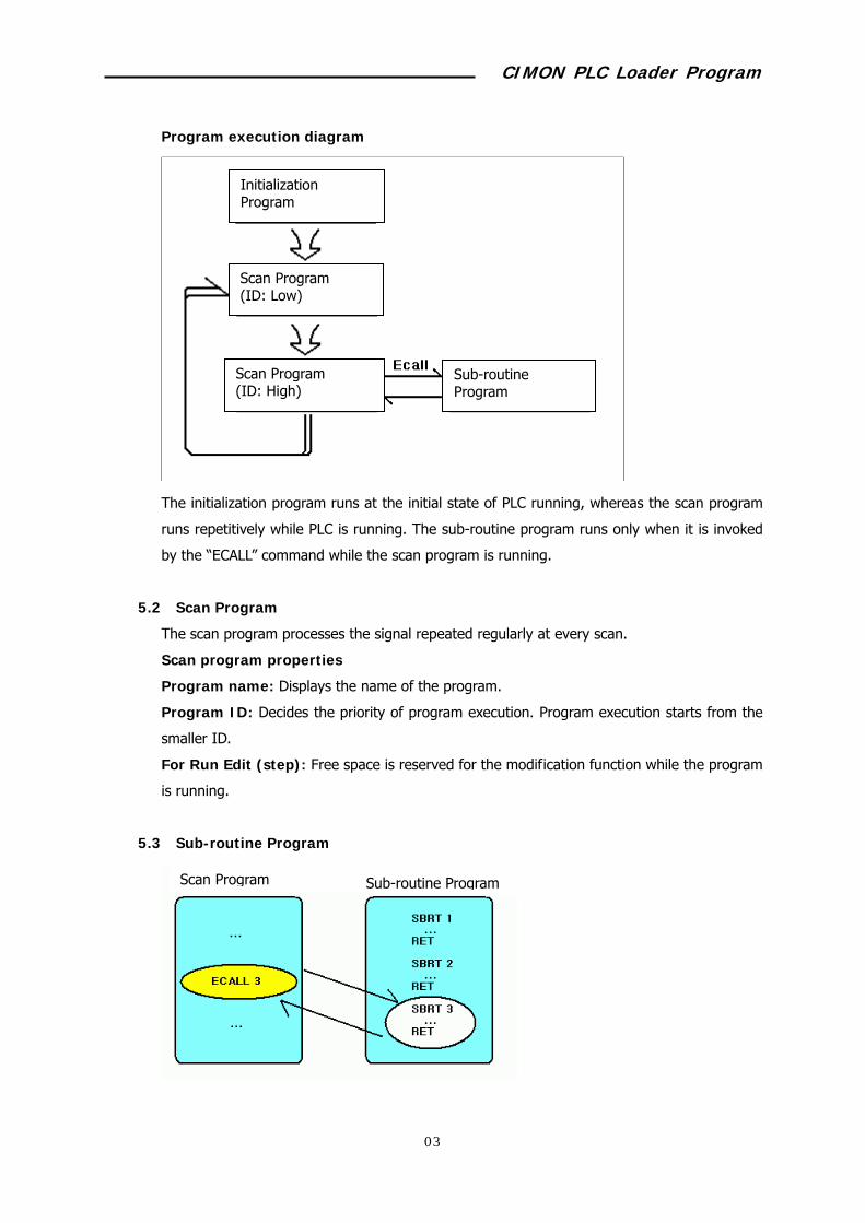
Program execution diagram
The initialization program runs at the initial state of PLC running, whereas the scan program
runs repetitively while PLC is running. The sub-routine program runs only when it is invoked
by the “ECALL” command while the scan program is running.
5.2 Scan Program
The scan program processes the signal repeated regularly at every scan.
Scan program properties
Program name: Displays the name of the program.
Program ID: Decides the priority of program execution. Program execution starts from the
smaller ID.
For Run Edit (step): Free space is reserved for the modification function while the program
is running.
5.3 Sub-routine Program
Initialization Program
Sub-routineProgram
Scan Program (ID: High)
Scan Program (ID: Low)
Scan Program Sub-routine Program

CIMON PLC Loader Program
26
A collection of programs that are executed by the “ECALL” command in the scan program.
The scan program executes SBRT n ~ RET commands in the sub-routine program according
to the “ECALL” command.
5.4 Initialization Program (Cold)
Program that is started when the power is supplied or the mode is changed to the Run mode.
The scan program can be executed after running of the initialization program is complete.
It also sets the initialization data to run the scan program or initializes the peripheral or
special module.
Use the “INITEND” command to stop the initialization program.
5.5 Initialization Program (Hot)
Set the Hot Restart function in the PLC Parameter window. Once this function is selected, it
will be started if the temporary power failure is within the setting time.

CIMON PLC Loader Program
27
Run the initialization program (hot) while keeping previous values (device values at the time
of power off) and then, run the scan program.
Use the “INITEND” command to stop the initialization program.
5.6 Periodic Interrupt Program
The selected program will be executed at the interrupt interval.
How to set the interrupt program
Set the unique interrupt ID with the digits from 0 to 15.
Free space is reserved for the modification function while the program is running.
The interrupt with lower priority will be executed first. Priority of the program must not be
same with other program.
Input the interrupt interval, which is the interval of program execution. The allowable setting
range is 10 ~ 655.350ms.
To run the interrupt program, use the “GEI” command to enable the usage of the interrupt
program and then, execute the program using the “EI” command.

CIMON PLC Loader Program
28
6 Programming (Multiple Programs) 6.1 Contents of Example Programs
Add the following functions to the example program in the chapter 4.
Fill D00000~D00100 with 10 for PLC operation, using the initialization program (Cold).
Turn the lamp (Y0000) on for 5 seconds and turn it off for 3 seconds repetitively, using the
timer contact.
6.2 Adding/Deleting a Program
Click the right mouse button on the Program in the Project window, in order to add a new
program.
Select the Initialization Program (Cold) and set program name, ID, and free space.

CIMON PLC Loader Program
29
You can check the newly registered program in the Project window.
Deleting the program from the project
Select the program to delete fist.
Click the right mouse button on the selected program, and select the “Remove Program
from Project” popup menu.
6.3 Writing/Managing Program
Writing a program
Double click the Initialization Program in the Project window.
Write the initialization program in the LD Editing window.
Insert a blank line in the Edit window using [Ctrl+L] key and then, click the button to
input the contact “F0012”.

CIMON PLC Loader Program
30
Click the button to input the “FMOV” command.
Insert a blank line using [Ctrl+L] key and click the button to input “F0012.”
Click the button to input the “INITEND” command.
CIMON PLC Loader Program
31
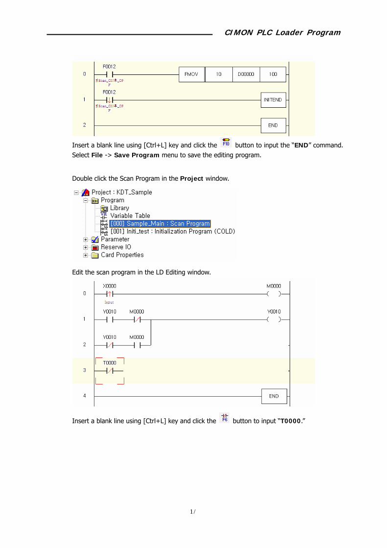
Insert a blank line using [Ctrl+L] key and click the button to input the “END” command. Select File -> Save Program menu to save the editing program.
Double click the Scan Program in the Project window.
Edit the scan program in the LD Editing window.
Insert a blank line using [Ctrl+L] key and click the button to input “T0000.”
CIMON PLC Loader Program
32
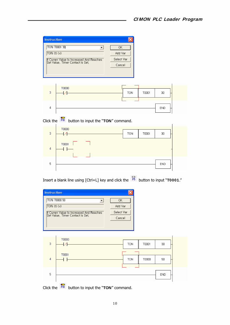
Click the button to input the “TON” command.
Insert a blank line using [Ctrl+L] key and click the button to input “T0001.”
Click the button to input the “TON” command.
CIMON PLC Loader Program
33
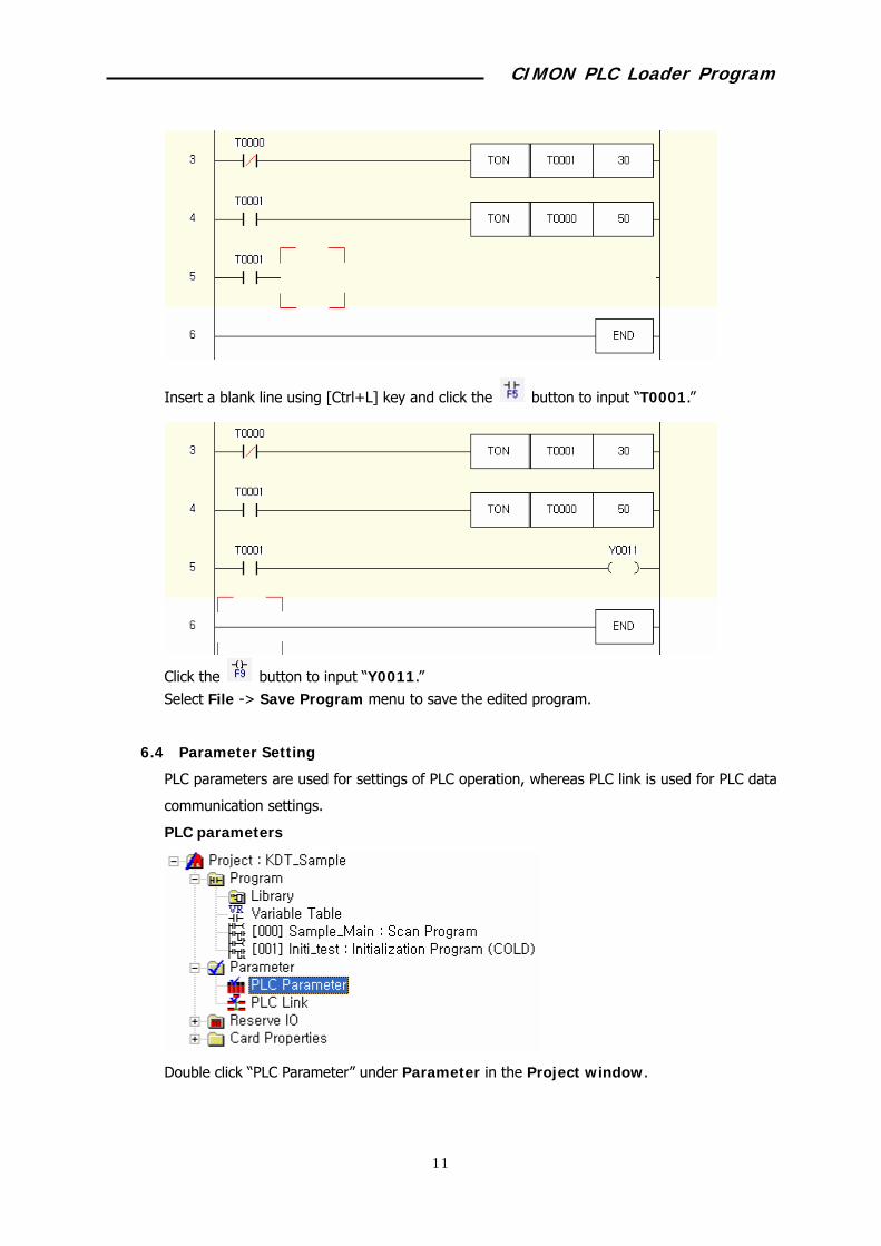
Insert a blank line using [Ctrl+L] key and click the button to input “T0001.”
Click the button to input “Y0011.” Select File -> Save Program menu to save the edited program.
6.4 Parameter Setting
PLC parameters are used for settings of PLC operation, whereas PLC link is used for PLC data
communication settings.
PLC parameters
Double click “PLC Parameter” under Parameter in the Project window.

CIMON PLC Loader Program
34
Default setting
Normal action on error: If this option is selected, PLC will run normally even though the
operation error occurs while the scan program is running.
Output while debugging: Enables output display during debugging.
Timer: Sets the contact area that will run 100ms or 10ms among 1,024 timer contacts.
Remote write: Enables PC control using the communication module.
Remote mode change: Enables to change the PLC operation module using the
communication module.
PLC Link (Com/Dual) Auto Change: Enables automatic PLC link switching function. This
option is valid only for the CPU supporting redundancy.
Watch Dog Timer: If you click “Use WDT,” the watch dog timer is enabled. If the PC scan
time exceeds the setting time, the WDT error will be generated.
Hot Restart: If the power supply is resumed within the defined time, the initialization
program (hot) will be executed while keeping the PLC memory value. To use this function,
the CPU should be equipped with RTC.
Expantion: Sets PLC increment number as much as you want. If the number in the
increment end is smaller than the setting value, the increment communication error will occur.
Latch Setup
Sets the PLC latch area. If you click the button with the device name on it, you can set the
area.
Latch area values will be maintained even though PLC stops or the power is turned off.

CIMON PLC Loader Program
35
Interrupt
Manages interrupt programs registered in the project. You can modify the interrupt interval
and priority in this window.
Error Action
Sets the actions to be taken when the PLC error occurs.
CIMON PLC Loader Program
36
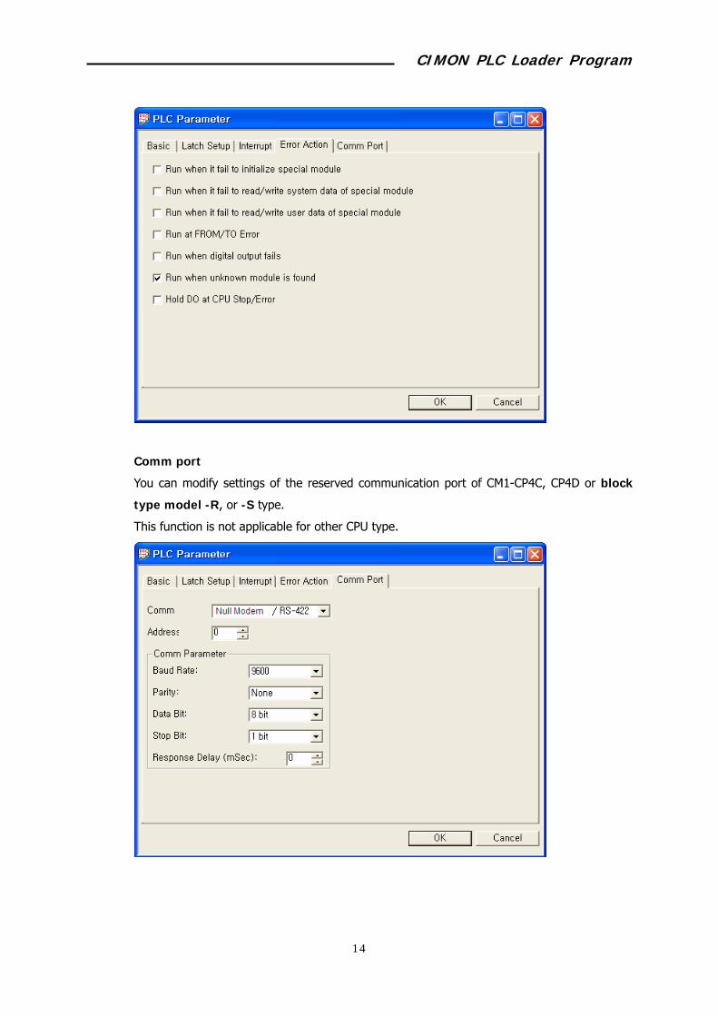
Comm port
You can modify settings of the reserved communication port of CM1-CP4C, CP4D or block
type model -R, or -S type.
This function is not applicable for other CPU type.
CIMON PLC Loader Program
37
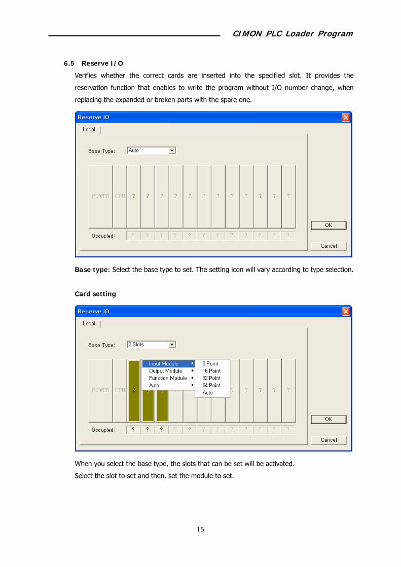
6.5 Reserve I/O
Verifies whether the correct cards are inserted into the specified slot. It provides the
reservation function that enables to write the program without I/O number change, when
replacing the expanded or broken parts with the spare one.
Base type: Select the base type to set. The setting icon will vary according to type selection.
Card setting
When you select the base type, the slots that can be set will be activated.
Select the slot to set and then, set the module to set.

CIMON PLC Loader Program
38
If 64 points input is selected, the bar will be displayed in light green color and “DI” will be
displayed at the center, as shown above.
The “Occupied” means how many (4*16=64) addresses are occupied by the specified slot.

CIMON PLC Loader Program
39
7 PLC Control 7.1 PLC Operation Control
PLC status
You can check the current PLC status, firmware version, and so on.
Select Online -> PLC Status menu while connected to PLC.
PLC time setting
You can set the time in the PLC Time Setting window if the CPU is integrated with RTC.
To synchronize the current time in the PC with that of PLC, click [Get PC Time] button and
the [OK] button.
Change operation mode
CIMON PLC Loader Program
40
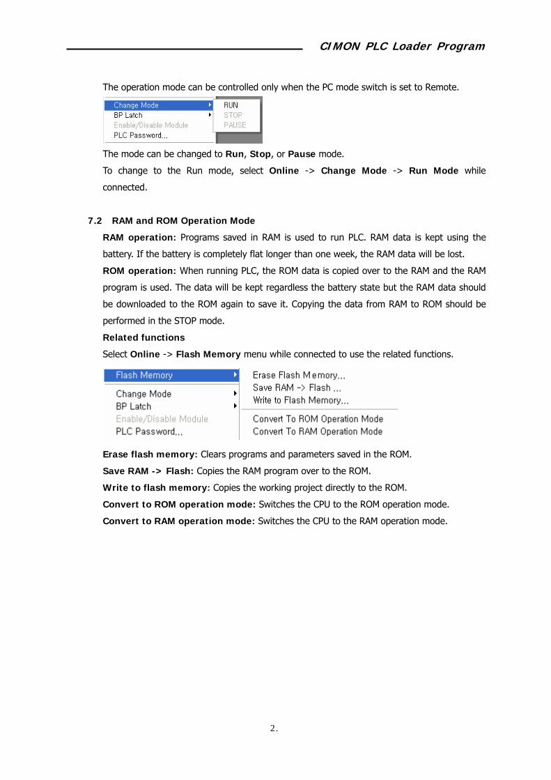
The operation mode can be controlled only when the PC mode switch is set to Remote.
The mode can be changed to Run, Stop, or Pause mode.
To change to the Run mode, select Online -> Change Mode -> Run Mode while
connected.
7.2 RAM and ROM Operation Mode
RAM operation: Programs saved in RAM is used to run PLC. RAM data is kept using the
battery. If the battery is completely flat longer than one week, the RAM data will be lost.
ROM operation: When running PLC, the ROM data is copied over to the RAM and the RAM
program is used. The data will be kept regardless the battery state but the RAM data should
be downloaded to the ROM again to save it. Copying the data from RAM to ROM should be
performed in the STOP mode.
Related functions
Select Online -> Flash Memory menu while connected to use the related functions.
Erase flash memory: Clears programs and parameters saved in the ROM.
Save RAM -> Flash: Copies the RAM program over to the ROM.
Write to flash memory: Copies the working project directly to the ROM.
Convert to ROM operation mode: Switches the CPU to the ROM operation mode.
Convert to RAM operation mode: Switches the CPU to the RAM operation mode.
CIMON PLC Loader Program
41
8 Setting Special Card Double click the module to set in the Module Property of the Project window while connected
to PLC, or select Tools -> Optional Module Setup menu.
8.1 Ethernet Module
Select Tools -> Optional Module Setup -> Ethernet Module menu.
If several Ethernet modules are mounted, you can select the intended card by specifying
base and slot.
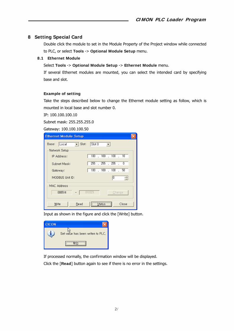
Example of setting
Take the steps described below to change the Ethernet module setting as follow, which is
mounted in local base and slot number 0.
IP: 100.100.100.10
Subnet mask: 255.255.255.0
Gateway: 100.100.100.50
Input as shown in the figure and click the [Write] button.
If processed normally, the confirmation window will be displayed.
Click the [Read] button again to see if there is no error in the settings.
CIMON PLC Loader Program
42
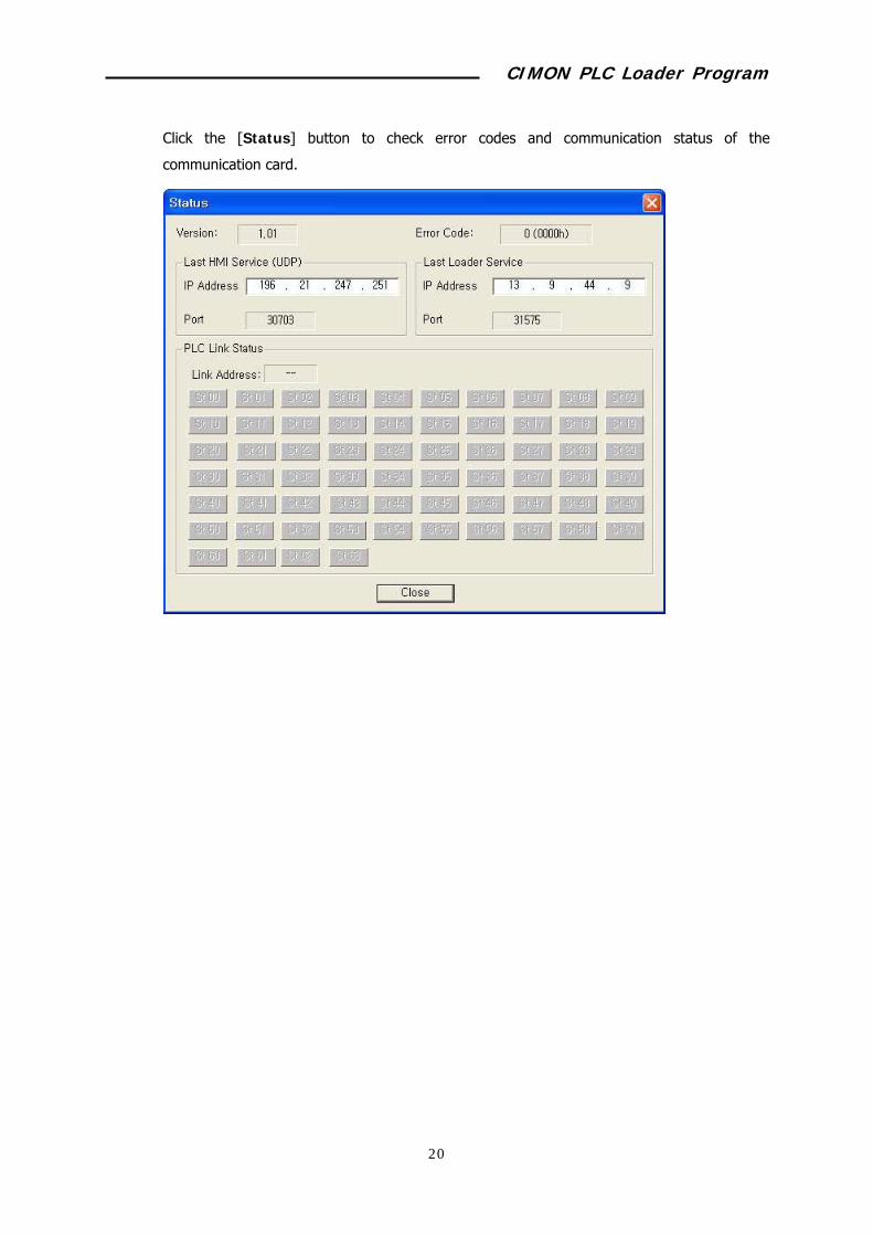
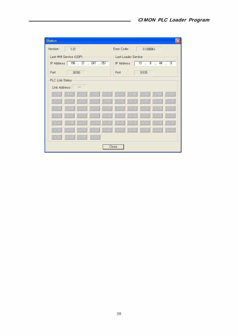
Click the [Status] button to check error codes and communication status of the
communication card.
CIMON PLC Loader Program
43
8.2 RS232/422 Module
Select Tools -> Optional Module Setup -> RS232/422 Module.
If several RS232/422 modules are mounted, you can change the target card by specifying
base and slot.
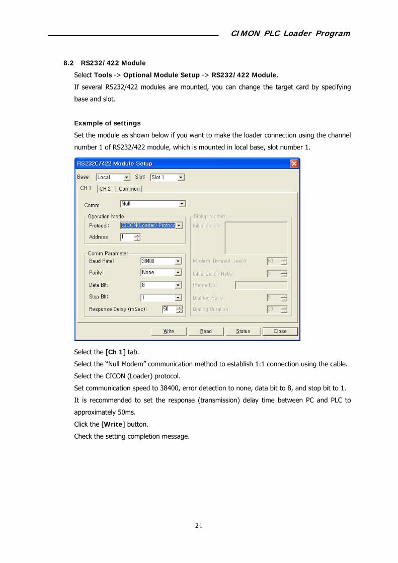
Example of settings
Set the module as shown below if you want to make the loader connection using the channel
number 1 of RS232/422 module, which is mounted in local base, slot number 1.
Select the [Ch 1] tab.
Select the “Null Modem” communication method to establish 1:1 connection using the cable.
Select the CICON (Loader) protocol.
Set communication speed to 38400, error detection to none, data bit to 8, and stop bit to 1.
It is recommended to set the response (transmission) delay time between PC and PLC to
approximately 50ms.
Click the [Write] button.
Check the setting completion message.
CIMON PLC Loader Program
44
8.3 Logger (RS-232) Module
Select Tools -> Optional Module Setup -> Logger (RS-232) Module menu.
If several RS232/422 modules are mounted, you can change the target card by specifying
base and slot.
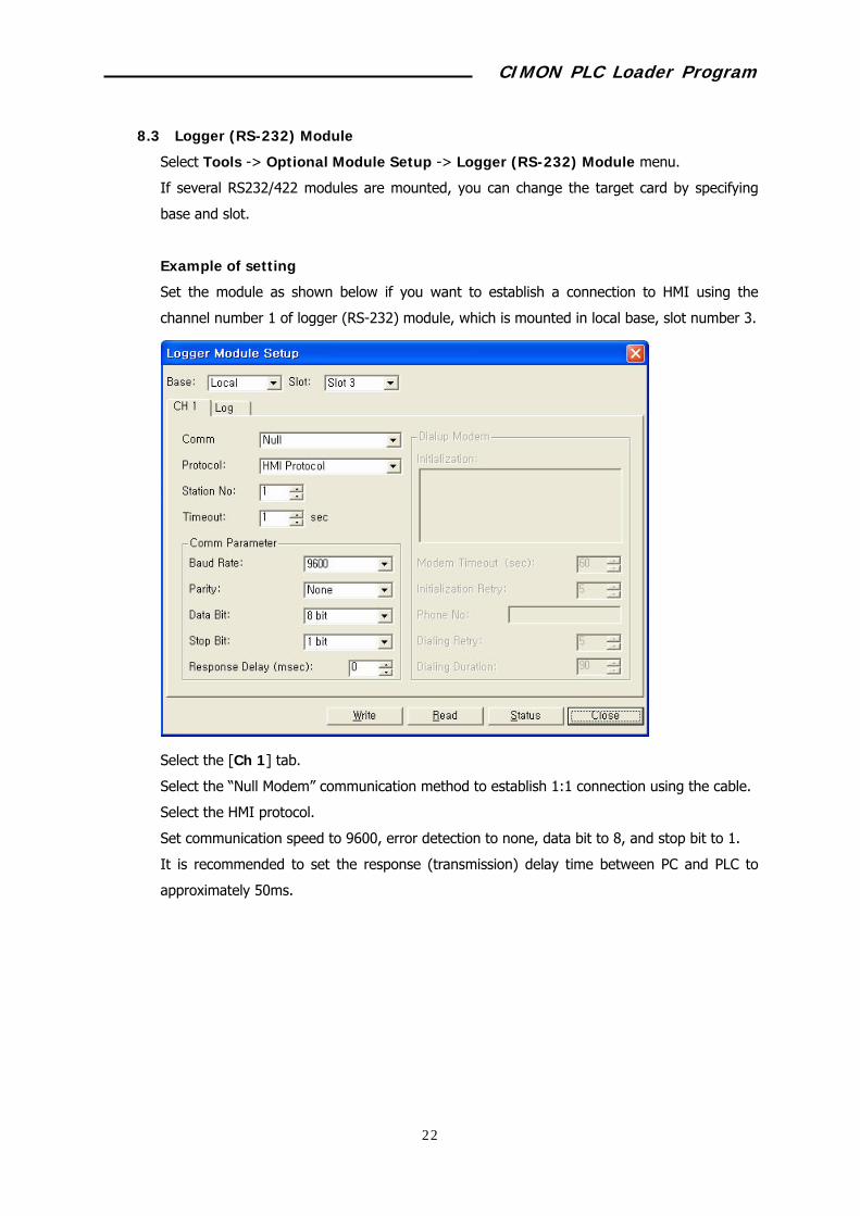
Example of setting
Set the module as shown below if you want to establish a connection to HMI using the
channel number 1 of logger (RS-232) module, which is mounted in local base, slot number 3.
Select the [Ch 1] tab.
Select the “Null Modem” communication method to establish 1:1 connection using the cable.
Select the HMI protocol.
Set communication speed to 9600, error detection to none, data bit to 8, and stop bit to 1.
It is recommended to set the response (transmission) delay time between PC and PLC to
approximately 50ms.

CIMON PLC Loader Program
45
Click the Log tab.
Take the following steps to log the data of “D00000.”
Select the logging method (“Sampling”).
Input the logging interval (1000).
Click the “Delete transmitted log data.” option.
Double click the block to designate (block #0).
Select the device type (D).
Input the starting address (0).
Select the data type (word).
If the data type is word, Deadband/Bit is meaningless. Set any number (0).
Click the [OK] button.
Click the [Write] button.
Check the OK message.

CIMON PLC Loader Program
46
8.4 DNP3 (Ethernet) Module
Select Tools -> Optional Module Setup -> DNP3 (Ethernet) Module menu.
If several DNP3 (Ethernet) modules are mounted, you can change the target card by
specifying base and slot.
Example of settings
When establishing a DNP communication by changing settings of the DNP3 (Ethernet)
module mounted in local base, slot 4.
IP: 100.100.100.10
Subnet mask: 255.255.255.0
Gateway: 100.100.100.50
Select the Basic Setup tab.
Input parameters as shown above.
CIMON PLC Loader Program
47
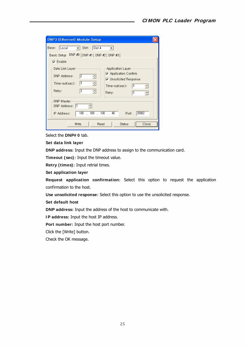
Select the DNP#0 tab.
Set data link layer
DNP address: Input the DNP address to assign to the communication card.
Timeout (sec): Input the timeout value.
Retry (times): Input retrial times.
Set application layer
Request application confirmation: Select this option to request the application
confirmation to the host.
Use unsolicited response: Select this option to use the unsolicited response.
Set default host
DNP address: Input the address of the host to communicate with.
IP address: Input the host IP address.
Port number: Input the host port number.
Click the [Write] button.
Check the OK message.
CIMON PLC Loader Program
48
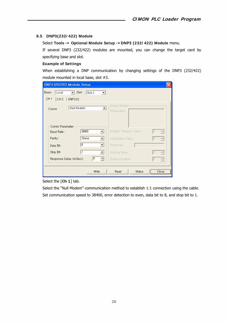
8.5 DNP3(232/422) Module
Select Tools -> Optional Module Setup ->DNP3 (232/422) Module menu.
If several DNP3 (232/422) modules are mounted, you can change the target card by
specifying base and slot.
Example of Settings
When establishing a DNP communication by changing settings of the DNP3 (232/422)
module mounted in local base, slot #3.
Select the [Ch 1] tab.
Select the “Null Modem” communication method to establish 1:1 connection using the cable.
Set communication speed to 38400, error detection to even, data bit to 8, and stop bit to 1.

CIMON PLC Loader Program
49
Select the DNP3.0 tab.
Set data link layer
DNP address: Input the DNP address to assign to the communication card.
Timeout (sec): Input the timeout value.
Retry : Input retrial times.
Application layer
Application confirmation: Select this option to request the application confirmation to the
host.
Unsolicited response: Select this option to use the unsolicited response.
Set Dnp Master
DNP address: Input the address of the Master to communicate with.
Click the [Write] button.
Check the OK message.
CIMON PLC Loader Program
50
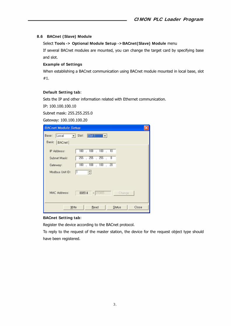
8.6 BACnet (Slave) Module
Select Tools -> Optional Module Setup ->BACnet(Slave) Module menu
If several BACnet modules are mounted, you can change the target card by specifying base
and slot.
Example of Settings
When establishing a BACnet communication using BACnet module mounted in local base, slot
#1.
Default Setting tab:
Sets the IP and other information related with Ethernet communication.
IP: 100.100.100.10
Subnet mask: 255.255.255.0
Gateway: 100.100.100.20
BACnet Setting tab:
Register the device according to the BACnet protocol.
To reply to the request of the master station, the device for the request object type should
have been registered.

CIMON PLC Loader Program
51
The Network Number filed is used to identify the specific BACnet module when several
BACnet modules exist in the same network. Master separates slaves to request the data,
using the network number.
Register a new device using the [Add] button.
Set as described below to set analog input (object type) as 100 words from D00400.
Click the [Add] button.
Select “Analog Value (Word)” as the object type.
Input “D00400” in the PLC Device Address field.
Input “100" in the Number Of Object(s) field.
Click the [OK] button.
Click the [Status] button to check error codes and the communication status of the
communication card.
CIMON PLC Loader Program
52

CIMON PLC Loader Program
53
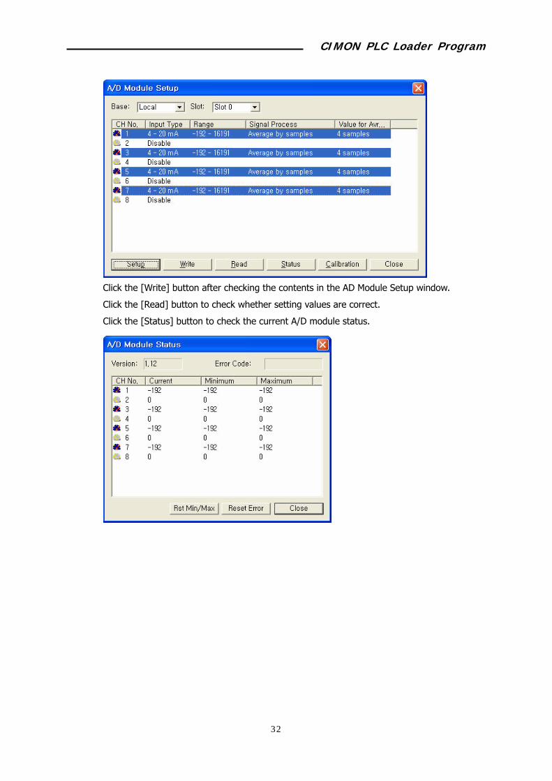
8.7 AD Conversion Module
Select Tools -> Optional Module Setup -> AD Module menu.
If several AD conversion modules are mounted, you can change the target card by specifying
base and slot.
Example of Settings
When calculating the average of 4 times sampling after 4 ~ 20mA analog input of the AD
conversion module channel 1, 3, 5, and 7 to 0 ~ 160000, which are mounted in local base,
slot #0.
Click the channel (1, 3, 5, and 7) to set while pressing down the Shift key.
Click the [Setup] button.
Select the Input Type (4 – 20mA).
Select the Digital Value Range (-192 – 16191).
Select the Signal Processing (Get the sampling average as much as the standard value).
Input the Value For Average (4).
Click the [OK] button.
CIMON PLC Loader Program
54
Click the [Write] button after checking the contents in the AD Module Setup window.
Click the [Read] button to check whether setting values are correct.
Click the [Status] button to check the current A/D module status.
CIMON PLC Loader Program
55
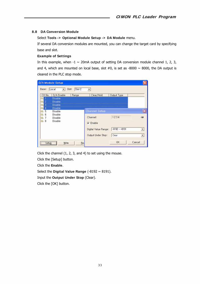
8.8 DA Conversion Module
Select Tools -> Optional Module Setup -> DA Module menu.
If several DA conversion modules are mounted, you can change the target card by specifying
base and slot.
Example of Settings
In this example, when -1 ~ 20mA output of setting DA conversion module channel 1, 2, 3,
and 4, which are mounted on local base, slot #0, is set as -8000 ~ 8000, the DA output is
cleared in the PLC stop mode.
Click the channel (1, 2, 3, and 4) to set using the mouse.
Click the [Setup] button.
Click the Enable.
Select the Digital Value Range (-8192 ~ 8191).
Input the Output Under Stop (Clear).
Click the [OK] button.

CIMON PLC Loader Program
56
Click the [Write] button after checking the contents in the D/A Module Setting window.
Click the [Read] button to check whether setting values are correct.
Click the [Status] button to check the current D/A module status, and insert the D/A output
temporarily.
Example of Settings
Take the following steps to send 12mA output to the DA module channel #1.
Check whether PLC is in the Run mode.
Click the [Module Status] button to display the “RTD Module Status” window.
Select the channel #1 and click [Set Output] button.
Select the Allow option in the Disable/Enable Output window, and click the [OK] button.

CIMON PLC Loader Program
57
Click the [Set Value] button.
Input the output value (0) on the “set Value” window.
Click the [OK] button.
CIMON PLC Loader Program
58
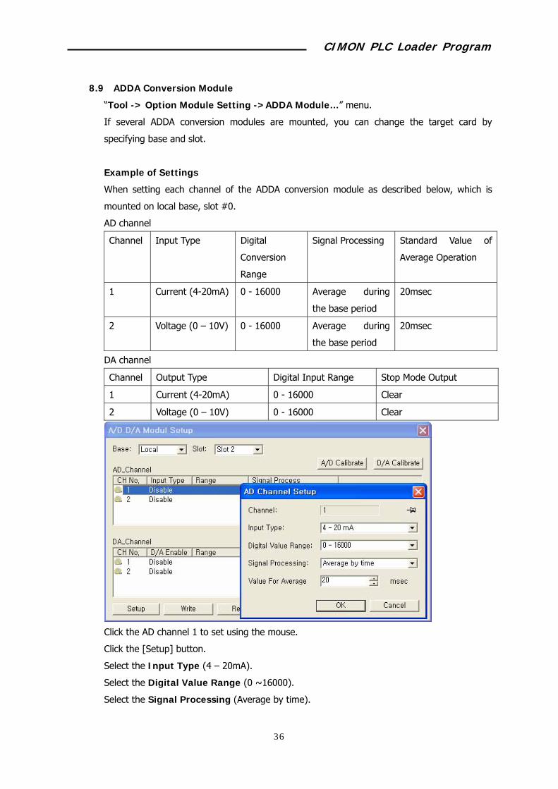
8.9 ADDA Conversion Module
“Tool -> Option Module Setting ->ADDA Module…” menu.
If several ADDA conversion modules are mounted, you can change the target card by
specifying base and slot.
Example of Settings
When setting each channel of the ADDA conversion module as described below, which is
mounted on local base, slot #0.
AD channel
Channel Input Type Digital
Conversion
Range
Signal Processing Standard Value of
Average Operation
1 Current (4-20mA) 0 - 16000 Average during
the base period
20msec
2 Voltage (0 – 10V) 0 - 16000 Average during
the base period
20msec
DA channel
Channel Output Type Digital Input Range Stop Mode Output
1 Current (4-20mA) 0 - 16000 Clear
2 Voltage (0 – 10V) 0 - 16000 Clear
Click the AD channel 1 to set using the mouse.
Click the [Setup] button.
Select the Input Type (4 – 20mA).
Select the Digital Value Range (0 ~16000).
Select the Signal Processing (Average by time).

CIMON PLC Loader Program
59
Input the Value for average (20).
Click the [OK] button.
Set the AD channel 2 using the same method.
However, set the Input Signal to “0 – 10V.”
Click the AD channel 1 to set using the mouse.
Click the [Setup] button.
Click the Enable.
Select the Digital Value Range (-192 ~ 16191).
Set the Output Type (Current).
Input the Output Under Stop (Clear).
Click the [OK] button.
Set the DA channel 2 using the same method.
However, set Voltage as the Select Output Type.

CIMON PLC Loader Program
60
Click the [Write] button after checking the contents in the A/D D/A Module Setting window.
Click the [Read] button to check whether setting values are correct.
Click the [Status] button to check the current A/D D/A module status, and insert the D/A
output temporarily.
CIMON PLC Loader Program
61
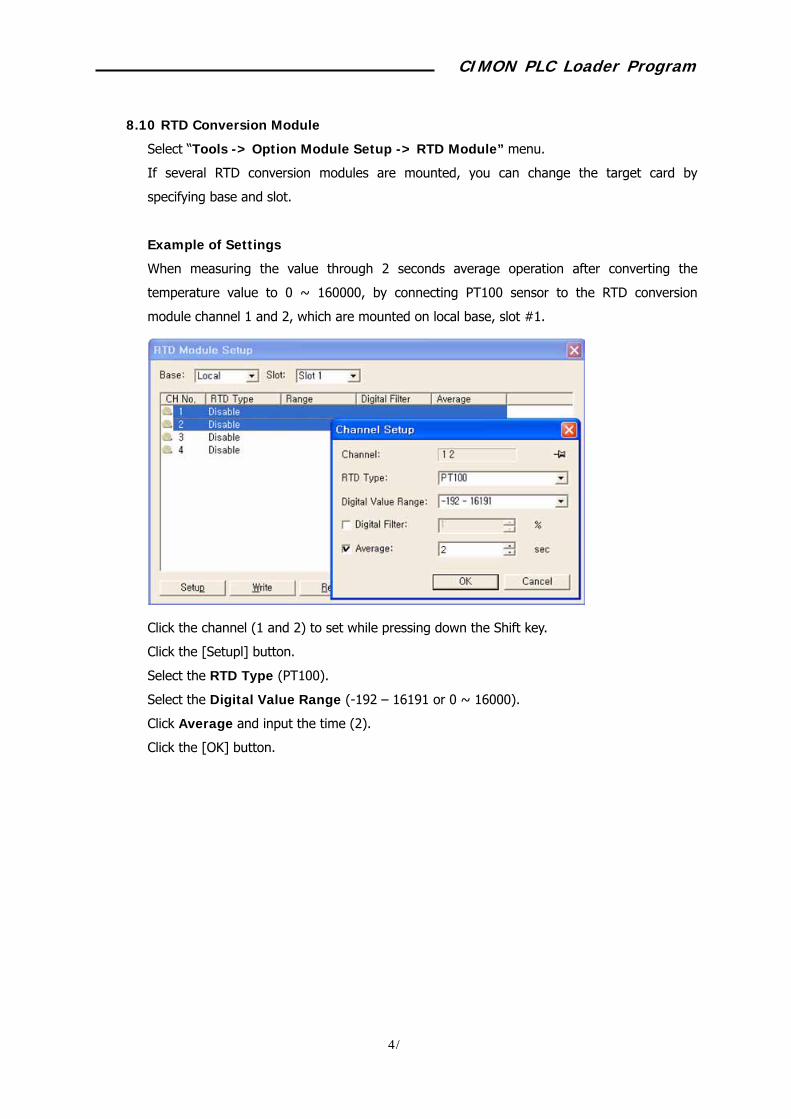
8.10 RTD Conversion Module
Select “Tools -> Option Module Setup -> RTD Module” menu.
If several RTD conversion modules are mounted, you can change the target card by
specifying base and slot.
Example of Settings
When measuring the value through 2 seconds average operation after converting the
temperature value to 0 ~ 160000, by connecting PT100 sensor to the RTD conversion
module channel 1 and 2, which are mounted on local base, slot #1.
Click the channel (1 and 2) to set while pressing down the Shift key.
Click the [Setupl] button.
Select the RTD Type (PT100).
Select the Digital Value Range (-192 – 16191 or 0 ~ 16000).
Click Average and input the time (2).
Click the [OK] button.
CIMON PLC Loader Program
62
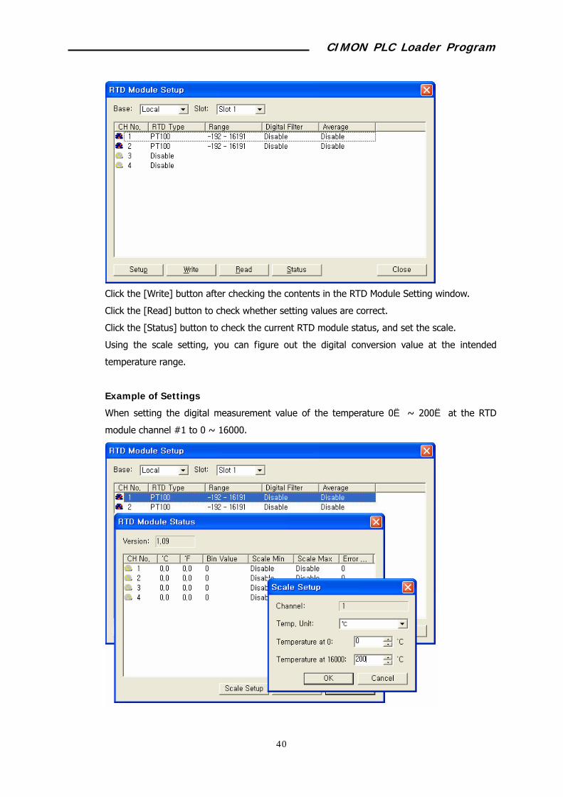
Click the [Write] button after checking the contents in the RTD Module Setting window.
Click the [Read] button to check whether setting values are correct.
Click the [Status] button to check the current RTD module status, and set the scale.
Using the scale setting, you can figure out the digital conversion value at the intended
temperature range.
Example of Settings
When setting the digital measurement value of the temperature 0 ~ 200℃ ℃ at the RTD
module channel #1 to 0 ~ 16000.
CIMON PLC Loader Program
63
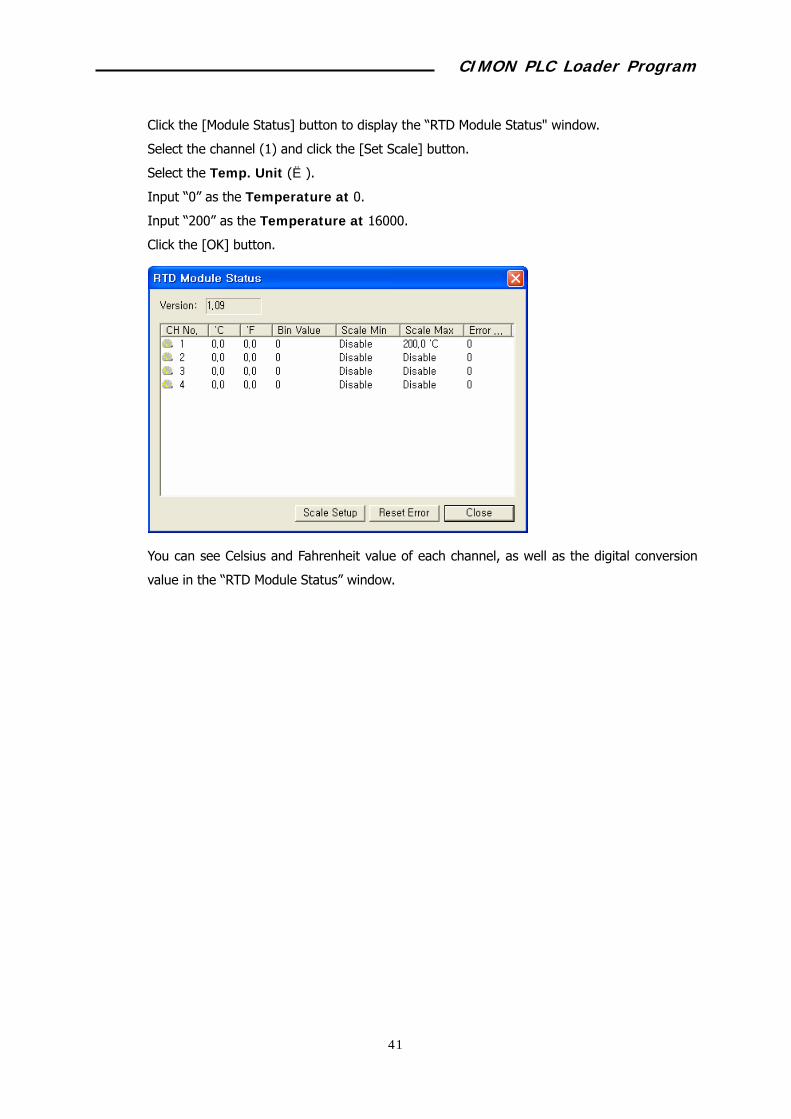
Click the [Module Status] button to display the “RTD Module Status" window.
Select the channel (1) and click the [Set Scale] button.
Select the Temp. Unit ( ).℃
Input “0” as the Temperature at 0.
Input “200” as the Temperature at 16000.
Click the [OK] button.
You can see Celsius and Fahrenheit value of each channel, as well as the digital conversion
value in the “RTD Module Status” window.

CIMON PLC Loader Program
64
8.11 TC Conversion Module
Select “Tools -> Option Module Setup -> TC Module…” menu.
If several TC conversion modules are mounted, you can change the target card by specifying
base and slot.
Example of Settings
When measuring the value through 4 seconds average operation after converting the
temperature value to 0 ~ 160000, by connecting K type sensor to the TC conversion module
channel 1 and 2, which are mounted on local base, slot #1.
Click the channel (1 and 2) to set while pressing down the Shift key.
Click the [Set Channel] button.
Select the TC Type (K).
Select the Digital Value Range (-192 – 16191 or 0 ~ 16000).
Click Average and input the time (4).
Click the [OK] button.
CIMON PLC Loader Program
65
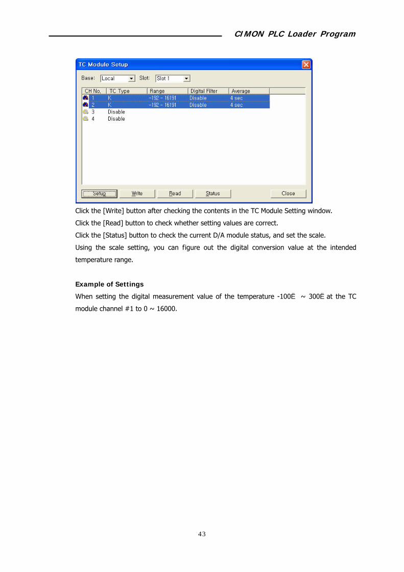
Click the [Write] button after checking the contents in the TC Module Setting window.
Click the [Read] button to check whether setting values are correct.
Click the [Status] button to check the current D/A module status, and set the scale.
Using the scale setting, you can figure out the digital conversion value at the intended
temperature range.
Example of Settings
When setting the digital measurement value of the temperature -100 ~ 300℃ ℃at the TC
module channel #1 to 0 ~ 16000.
CIMON PLC Loader Program
66
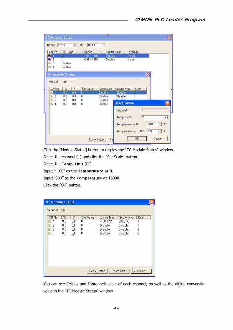
Click the [Module Status] button to display the “TC Module Status" window.
Select the channel (1) and click the [Set Scale] button.
Select the Temp. Unit ( ).℃
Input “-100” as the Temperature at 0.
Input “300” as the Temperature at 16000.
Click the [OK] button.
You can see Celsius and Fahrenheit value of each channel, as well as the digital conversion
value in the “TC Module Status” window.

CIMON PLC Loader Program
67
8.12 High-speed Counter
Select Tools -> Optional Module Setup -> High-speed Counter menu.
If several high-speed counter modules are mounted, you can change the target card by
specifying base and slot.
Example of Settings
When counting the input signal using the channel 1 of the high-speed counter mounted in
local base, slot #2, the input type should be “1 phase 1 multiplying" and the counter mode
should be a “linear counter.”
Set the Counter Mode of the channel 1 as the linear counter.
Input “1000” in the Preset. If the free set setting is required, the current counter value is
replaced with the preset setting value.
Input “2000” in the Value No. 1.
Input “3000” in the Value No. 2.
Select “Not Count” in the Counter Function Setup field. Counting will be enables only
when both "Counter Allowing Command” and “Start Counter Function” are on.
Select the Pulse Type – 1-Ph. Multiple of 1.
Click the [Write] button.
Click the [Read] button to check all settings are correct.
Click the [Status] button to check the current status of the high-speed counter.

CIMON PLC Loader Program
68
CIMON PLC Loader Program
69
9 Special Program 9.1 PID Special Program
The PID special program is designed to conveniently use the PID operation function, which is
the CPU built-in function.
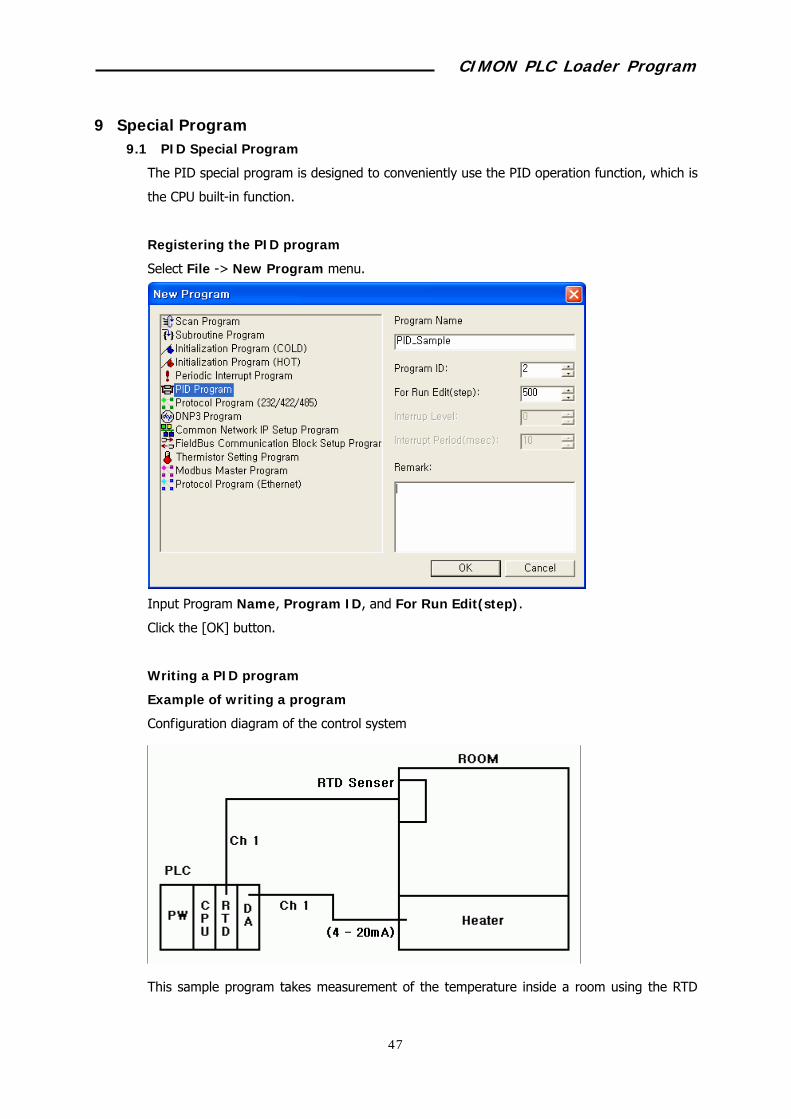
Registering the PID program
Select File -> New Program menu.
Input Program Name, Program ID, and For Run Edit(step).
Click the [OK] button.
Writing a PID program
Example of writing a program
Configuration diagram of the control system
This sample program takes measurement of the temperature inside a room using the RTD

CIMON PLC Loader Program
70
sensor, and controls 4 – 20mA output to keep the room temperature as settings.
Temperature is measure using the channel 1 of the RTD module, and the output is controlled
using the channel 1 of the DA card.
Number of entire loop(Total Loop)
Sets the number of loops that execute PID operation. One PID operation loop should be used
to control one controlling object. Up to 32 controlling objects can be set. Set “1” since there
is only 1 controlling object. (1 ~ 32)
Number of execution loops for 1 scan(1 Scan Loop)
Sets the number of execution loops in 1 scan when there are several loops. Set “1” as
the number of execution loops for 1 scan since the number of entire loop is 1.
PIDINIT starting area(PIDINIT Start)
Parameters to be referred by PIDINIT command are saved from the specified area. The
first loop uses 22 loops including the number of entire loop and execution loops for 1 scan.
From second loop, 20 words area is used whenever a new loop is added. In the above figure,
D00000 ~ D00021 area is set for the PIDINIT parameter area.

CIMON PLC Loader Program
71
PIDCAL starting area(PIDCAL Start)
Parameters to be referred by PIDCAL command and PIDCAL result value are saved from
the specified area. 20 words area is additionally used whenever a new loop is added. In the
above figure, D00100 ~ D00119 area is set for the PIDCAL parameter area. Be careful that
the area overlaps the PIDINIT area.
Current loop(Now Sel LooPp)
Select the loop to edit or monitor among the entire loop. "1" is set for the current loop field
since there is one loop.
Select operation formula (0: Forward operation, 1: Reverse operation)
Forward operation: Operation that makes the measurement value to be close to the target
value by outputting the movement volume (MV), if the measurement value (PV) is smaller
than the target value (SV). Heating operation belongs to this operation type.
Reverse operation: Operation that makes the PV to be close to the target value by
outputting the MV, if the PV is greater than the SV. Cooling operation belongs to this
operation type.
Select Forward operation (0) since heating is currently controlled.
Sampling time
Sets the interval of executing PID operation. The interval should be set shorter for the
system that the measurement value instantly responds to output variation.
Since it is set to 1 second in the above example, PID operation is performed at 1 second
interval and the MV changes. (0.01 ~ 60)
Proportional integer (Kp)
Constant value that is multiplies by the deviation (Sv –Pv) in the proportional operation “Mv
= Kp * (Sv – Pv)”, which performs proportional operation of PID control.
If the proportional integer (kp) is greater in the above formula, the PV reaches the SV faster.
However, if this value is too big, it can negatively affects stabilized control due to vibration.
In the above example, this value is set to 8000. It should be adjusted according to the
system while running the program. (0.01 ~ 100)
Integral integer (Ki)
The integral operation “Mv = P * E + P * 1/Ki *∫Edt” adds/deducts the deviation value
to/from the manipulation value depending on the time in order to remove the deviation, if
the difference (E) occurs between Sv and Pv. (0.0 ~ 3000)

CIMON PLC Loader Program
72
Proportional operation for the small difference does not significantly affect the change of the
manipulation value. Therefore, perform integral operation to obtain the difference removal
effect.
In the above example, this value is set to 2000. It should be adjusted according to the
system while running the program, like the proportional integer.
Differential integer (Kd)
The differential operation “Mv = Kp * E + Kp * dE/dt” suppresses occurrence of the
difference by computing the manipulation value that is proportional to speed change, in order
to remove the difference if it occurs due to the change of Sv or disturbance.
Differential time or differential integer is the time that the manipulation value of differential
operation becomes that of proportional operation since occurrence of the difference by
differential operation.
In the above example, this value is set to 0, which means no differential operation control.
(0.00 ~ 300)
Filter coefficient (Filter)
Sets the extent that the filter effect is applied for the measurement value (PV) that is entered
from the A/D card. (0.00 ~ 1)
Lower limit of MV (MV Low Limite)
Sets the lower limit of the MV that is calculated by PID operation at the time of automatic
PID operation.
If the MV is smaller than the lower MV limit (MVLL), the MVLL will be applied as the MV.
In the above example, the MVLL is set to 0. Therefore, the MV smaller than 0 will not be
displayed in the automatic operation mode. (0 ~ 16000)
Upper limit of MV (MV High Limite)
Sets the upper limit of the MV that is calculated by PID operation at the time of automatic
PID operation.
If the MV is greater than the lower MV limit (MVLL), the MVLL will be applied as the MV.
In the above example, the MVLL is set to 16000. Therefore, the MV bigger than 16000 will
not be displayed in the automatic operation mode. (0 ~ 16000)
Variation ratio limitation of MV (MV Change Limite)
The value set in this field will be applied, if MV variation is bigger than the variation ration
limitation of MV, when compares MV of the previous scan with that of this scan. (0 ~ 16000)
CIMON PLC Loader Program
73
In the above example, the variation ration limitation of MV is set to 6000. Therefore, the
variation amount will be set to 6000 if the operation result is bigger than 6000.
Automatic MV transfer (0: Use, 1: No use)
Use: If the user changes the PID control mode from automatic to manual, the MV calculated
in the automatic mode will be applied to the manual MV (MVman).
No use: The value set as MVman will be applied to the MV in the manual mode.
In the above example, this field is set to Use (1), MVman is equal to MV in the automatic
operation mode.
SV ramp (0: No use, 1~1000)
To suppress occurrence of overshoot due to abrupt change of the Sv, and control stably, if
the Sv is changed, the change is divided into the setting stage, and applied incrementally by
increasing/decreasing it by the sampling interval (Ts).
If set to “100" and Sv changes, Sv is incrementally applied internally at the interval of Ts
(sampling interval: 1 second), and it reaches the modified setting value after (Sv slope
function: 100)*Ts (time).
In the above example, it is set to “0". Therefore, this function will be disabled.
ON/OFF control time(On/Off time)
Sets the On/Off interval time to control PID using On/.Off control function. (If set to On, the
upper MV will be displayed as the MV.)
If the On/Off control time is set, the setting value becomes the on/off interval.
The ratio of On/Off in one interval is set by the current MV.
For example, if the setting value is 0.1 and the current MV is 80000, the On state will be kept
for 0.05 second and Off will be kept for 0.05 second. Or, if the MV is set to 32000, the On
state will be kept for 0.02 second, and Off state will be kept for 0.08 second.
In the above example, it is set to “0". Therefore, this function will be disabled.
Setting value (SV)
Input the target value to control.
For example, if 0 ~ 100% is used as the digital value of 0 ~ 16000, set 8000 in order to set
50%.
In the above example, the temperature value is controlled. Therefore, input “temperature to
set * 10”. For example, if temperature is 35.5℃, input 355. (0 ~ 16000)
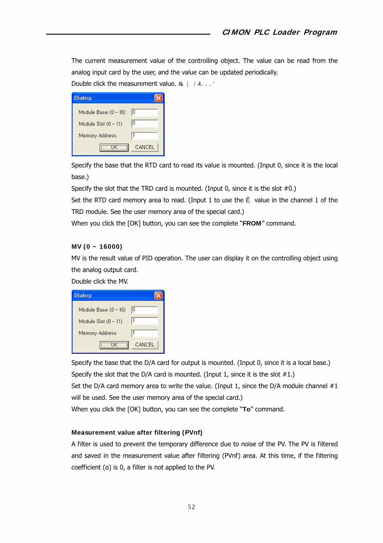
Procure value (PV)
CIMON PLC Loader Program
74
The current measurement value of the controlling object. The value can be read from the
analog input card by the user, and the value can be updated periodically.
Double click the measurement value. (0 ~ 16000)
Specify the base that the RTD card to read its value is mounted. (Input 0, since it is the local
base.)
Specify the slot that the TRD card is mounted. (Input 0, since it is the slot #0.)
Set the RTD card memory area to read. (Input 1 to use the ℃ value in the channel 1 of the
TRD module. See the user memory area of the special card.)
When you click the [OK] button, you can see the complete “FROM” command.
MV (0 ~ 16000)
MV is the result value of PID operation. The user can display it on the controlling object using
the analog output card.
Double click the MV.
Specify the base that the D/A card for output is mounted. (Input 0, since it is a local base.)
Specify the slot that the D/A card is mounted. (Input 1, since it is the slot #1.)
Set the D/A card memory area to write the value. (Input 1, since the D/A module channel #1
will be used. See the user memory area of the special card.)
When you click the [OK] button, you can see the complete “To” command.
Measurement value after filtering (PVnf)
A filter is used to prevent the temporary difference due to noise of the PV. The PV is filtered
and saved in the measurement value after filtering (PVnf) area. At this time, if the filtering
coefficient (α) is 0, a filter is not applied to the PV.

CIMON PLC Loader Program
75
MV Manual
If the PID mode is manual, PID is not controlled, and the value set as MVman will be
displayed as the MV.
Auto/Manual selection
Selects whether the controlling object will be controlled automatically using PID, or the value
set in the MVman area will be displayed.
PIDINIT state
Displays the error state occurred while initializing PID operation.
Save, Compile, and Download
Click the [Save] button if parameter setting is complete.
Select CICON menu -> Tools -> Compile+Link.
Select CICON menu -> Online -> Link+Download+Monitor to download the program
down to PLC.
If working is complete normally, the monitoring mode will be selected.
If you click the [Stop Monitoring] button, monitoring will be stopped and the editing mode
will be selected.
Monitoring
The monitoring result value will be displayed on the window during monitoring.
If you double click the current value during monitoring, you can modify the value in the
specified device area.
The modified value will be applied to PID control from the following scan.
To change the parameter during operation.
Check whether monitoring is in progress. (The current value is displayed during monitoring.)
Double click the current value of the parameter to modify.
Input the value that fits into the input value range, since it is displayed on the window
together with the specified device.

CIMON PLC Loader Program
76
PID AutoTuning
You can easily find parameters (proportional, integral, and differential integer) that are
appropriate for the system, using the automatic PID tuning function.
Note) Before starting automatic tuning, the environment should not affect the output value
as much as possible. In the above example, normal temperature is recommended that the
heater is not running.
Download the currently working PID program down to PLC.
Click the [Monitor] button in the PID program to enter into the monitoring mode.
Click the [Auto Tuning] button.
Input the setting value. (The setting value should be greater than the measurement value for
the forward control, in order to complete auto tuning normally. On the contrary, it should be
smaller than the measurement value, in case of the reverse control.)₩
The input value in the above example (forward direction) should be greater than the value
that is being measured currently. It is recommended to input the temperature set most
frequently (50 ).℃
Click the [OK] button.

CIMON PLC Loader Program
77
Auto Tuning is in Progress, and Auto Tuning Command is Received fields are turned
on in blue color, and auto tuning is started.
The output value is fixed at the upper limit value during auto tuning.
The system response characteristic at the maximum output is checked when processing
parameters.
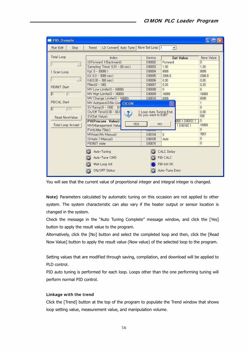
When auto tuning is completed, Auto Tuning is in Progress, and Auto Tuning
Command is Received fields are turned off, and parameters calculated by auto tuning will
be displayed on current values of Proportional Integer, Integral Integer, and
Differential Integer.
CIMON PLC Loader Program
78
You will see that the current value of proportional integer and integral integer is changed.
Note) Parameters calculated by automatic tuning on this occasion are not applied to other
system. The system characteristic can also vary if the heater output or sensor location is
changed in the system.
Check the message in the “Auto Tuning Complete” message window, and click the [Yes]
button to apply the result value to the program.
Alternatively, click the [No] button and select the completed loop and then, click the [Read
Now Value] button to apply the result value (Now value) of the selected loop to the program.
Setting values that are modified through saving, compilation, and download will be applied to
PLD control.
PID auto tuning is performed for each loop. Loops other than the one performing tuning will
perform normal PID control.
Linkage with the trend
Click the [Trend] button at the top of the program to populate the Trend window that shows
loop setting value, measurement value, and manipulation volume.
CIMON PLC Loader Program
79
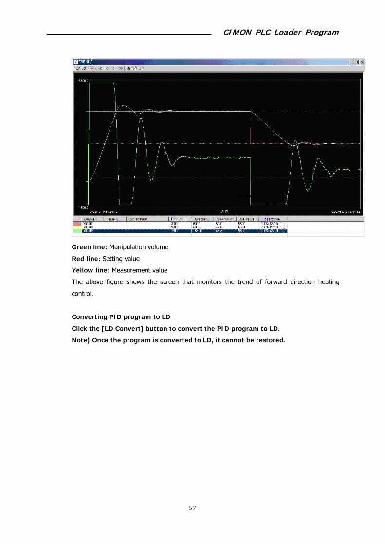
Green line: Manipulation volume
Red line: Setting value
Yellow line: Measurement value
The above figure shows the screen that monitors the trend of forward direction heating
control.
Converting PID program to LD
Click the [LD Convert] button to convert the PID program to LD.
Note) Once the program is converted to LD, it cannot be restored.

CIMON PLC Loader Program
80
9.2 Protocol Program
The protocol program enables the user to manually define the communication frame of the
serial communication module.
Registering the protocol program
Select File -> New Program menu.
Input the Program Name, Program ID, and Program Free Space field.
Click the [OK] button.
Composing protocol program
Example of writing a program
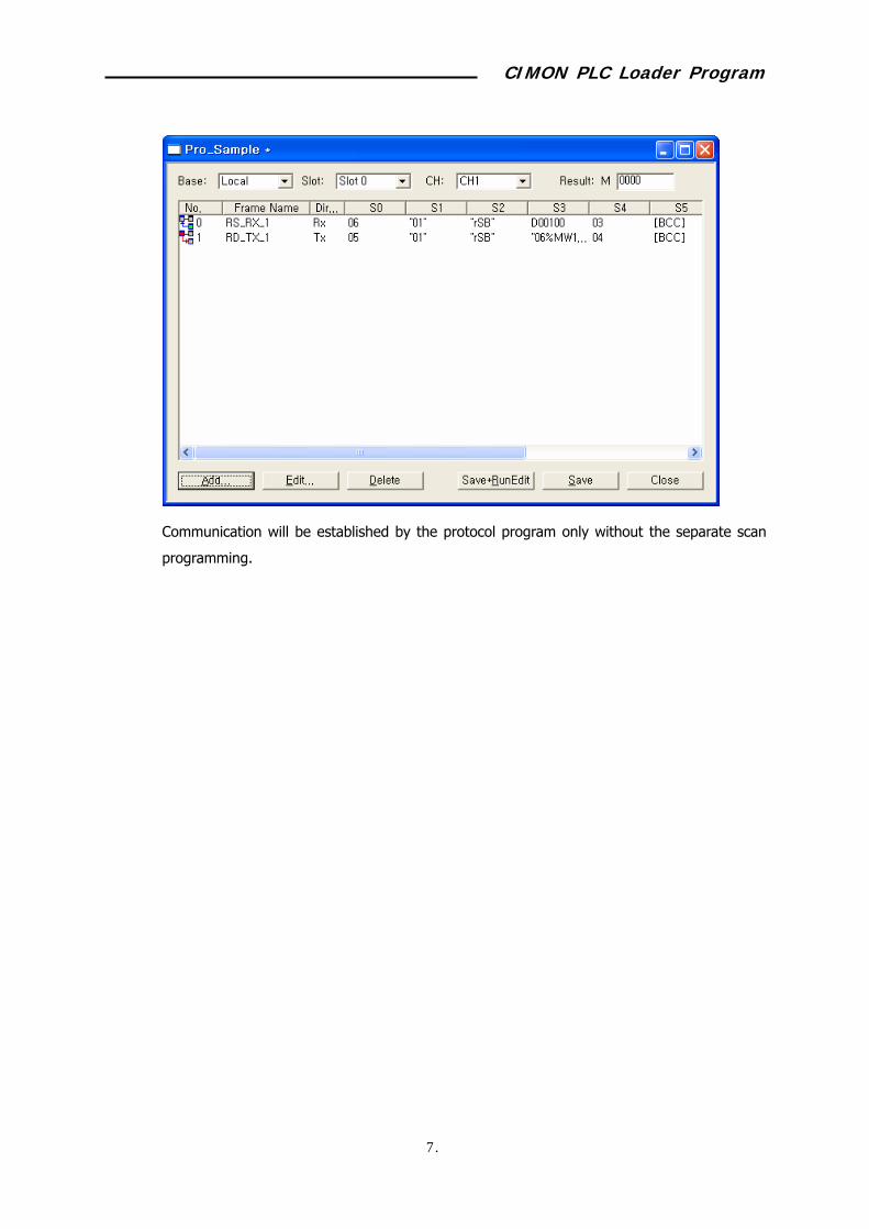
The sample program reads 5 words from %MW100 of Glofa PLC, and saves it in 5 words
from D00100 of CIMON PLC. Communication is established using the channel #1 (RS232) of
the serial communication module, which is mounted in local base, slot #0.
CIMON PLC Loader Program
81
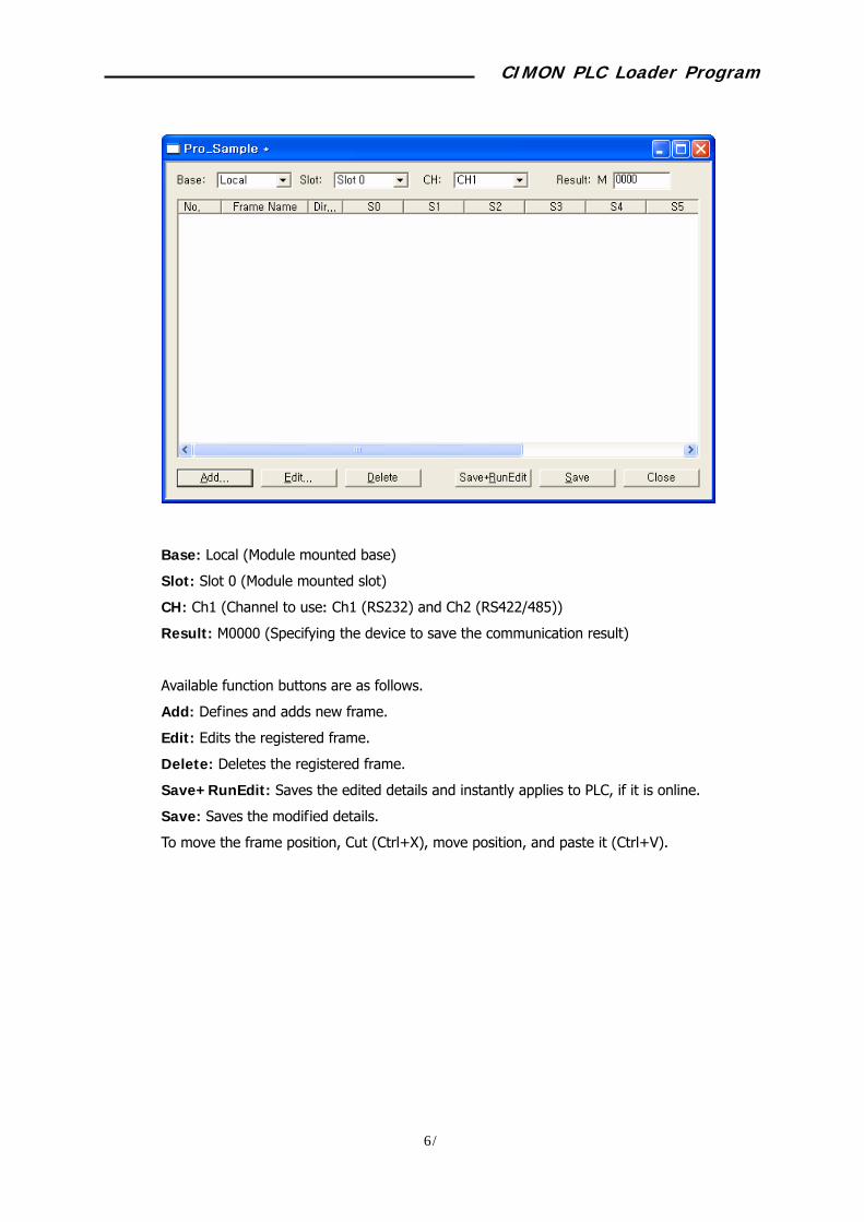
Base: Local (Module mounted base)
Slot: Slot 0 (Module mounted slot)
CH: Ch1 (Channel to use: Ch1 (RS232) and Ch2 (RS422/485))
Result: M0000 (Specifying the device to save the communication result)
Available function buttons are as follows.
Add: Defines and adds new frame.
Edit: Edits the registered frame.
Delete: Deletes the registered frame.
Save+RunEdit: Saves the edited details and instantly applies to PLC, if it is online.
Save: Saves the modified details.
To move the frame position, Cut (Ctrl+X), move position, and paste it (Ctrl+V).

CIMON PLC Loader Program
82
When you click the [Add] button, the Define Frame window will appear.
Input the setting items.
Frame: Name to separate the frame.
Tx/Rx: Sets the communication direction – sending or receiving.
Period: Sending frames will be automatically sent at the specified interval.
Tx frame by Rx: Specifies the frame that corresponds to the response.
Functions related with segment editing
Add segment: Defines and adds a new segment.
Edit segment: Edits the registered segment details.
Delete segment: Deletes the selected segment.
up: Moves the selected segment upwards.
down: Moves the selected segment downward.

CIMON PLC Loader Program
83
Defining a frame (Rx frame of the continuous read command for the direct variable)
Defines the frame contents to interpret the response frame for the continuous read
requesting frame of the Glofa PLC’s direct variable.
Defining a segment (header)
Sets the header of the protocol.
The header for the ACK response frame is ACK (06H), and should be set as shown
above.
Defining a segment (station number)
Sets the station number area for the protocol.
Input the station number of the counterpart (LG Glofa).
The station number is “01" (1) and should be set as shown above.
Defining a segment (command + command type)

CIMON PLC Loader Program
84
Continuous read command for the direct variable + command type “rSB”(r + SB),
which should be set as shown above.
Defining a segment (number of blocks + number of data)
The number of block is 1 and data is 10 (= 5Word * 2, 0AH), and should be set (01+0A) as
shown above.
Defining a segment (data)
CIMON PLC Loader Program
85
Set as shown above to save 5 word data received from Glofa PLC in 5 words from D00100 of
CIMON PLC.
To display 5 word data as an ASCII code, 20 bytes (= 5 words * 4 characters) are needed.
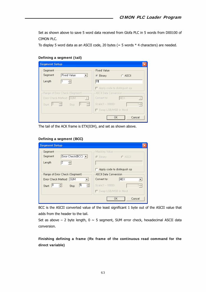
Defining a segment (tail)
The tail of the ACK frame is ETX(03H), and set as shown above.
Defining a segment (BCC)
BCC is the ASCII converted value of the least significant 1 byte out of the ASCII value that
adds from the header to the tail.
Set as above – 2 byte length, 0 ~ 5 segment, SUM error check, hexadecimal ASCII data
conversion.
Finishing defining a frame (Rx frame of the continuous read command for the
direct variable)

CIMON PLC Loader Program
86
The communication direction is the receiving frame, and set as shown above.
Defining a frame (Tx frame of the continuous read command for the direct variable)
Defines the request frame of the continuous read command for the direct variable.
Defining a segment (Header)
The header of the request frame is ENQ(05H), and set as shown above.

CIMON PLC Loader Program
87
Defining a segment (station number)
Set the station number as “01”(1).
(See the contents in the “Rx frame of the continuous read command for the direct variable”
section.)
Defining a segment (command + command type)
Set continuous read command for the direct variable + command type as “rSB.”
(See the contents in the “Rx frame of the continuous read command for the direct variable”
section.)
Defining a segment (variable length + variable name + number of data)
CIMON PLC Loader Program
88
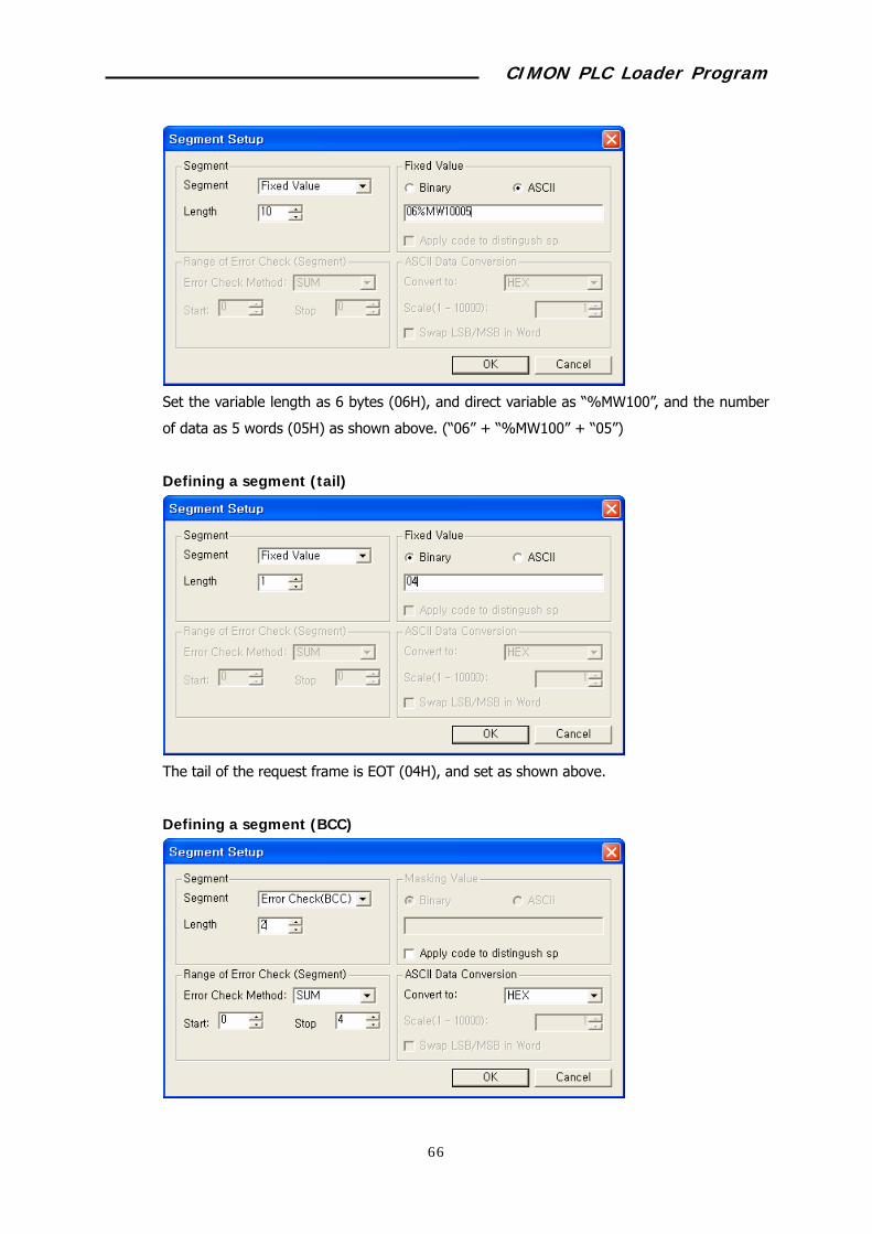
Set the variable length as 6 bytes (06H), and direct variable as “%MW100”, and the number
of data as 5 words (05H) as shown above. (“06” + “%MW100” + “05”)
Defining a segment (tail)
The tail of the request frame is EOT (04H), and set as shown above.
Defining a segment (BCC)

CIMON PLC Loader Program
89
BCC is the ASCII converted value of the least significant 1 byte out of the ASCII value that
adds from the header to the tail.
Set as above – 2 byte length, 0 ~ 5 segment, SUM error check, hexadecimal ASCII data
conversion.
Finishing defining a frame (Tx frame of the continuous read command for the
direct variable)
Set the communication direction as sending frame, and communication interval as 100msec,
and receiving frame for sending as RD_RX_1 as shown above.
Finishing frame registration (Continuous read request of the direct variable, as
receiving the response frame)
CIMON PLC Loader Program
90
Communication will be established by the protocol program only without the separate scan
programming.
CIMON PLC Loader Program
91
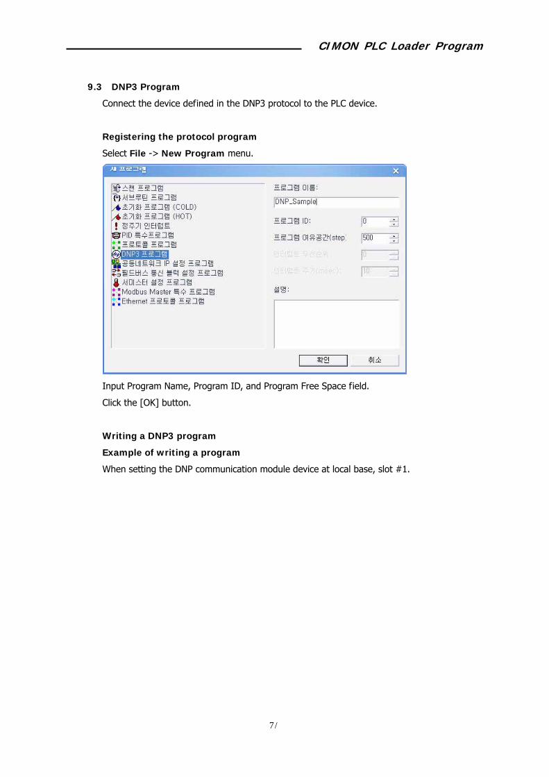
9.3 DNP3 Program
Connect the device defined in the DNP3 protocol to the PLC device.
Registering the protocol program
Select File -> New Program menu.
Input Program Name, Program ID, and Program Free Space field.
Click the [OK] button.
Writing a DNP3 program
Example of writing a program
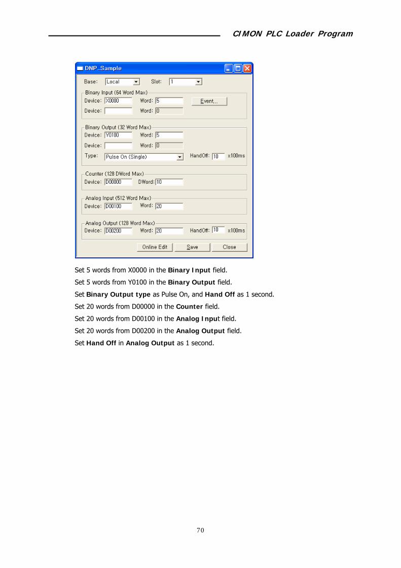
When setting the DNP communication module device at local base, slot #1.
CIMON PLC Loader Program
92
Set 5 words from X0000 in the Binary Input field.
Set 5 words from Y0100 in the Binary Output field.
Set Binary Output type as Pulse On, and Hand Off as 1 second.
Set 20 words from D00000 in the Counter field.
Set 20 words from D00100 in the Analog Input field.
Set 20 words from D00200 in the Analog Output field.
Set Hand Off in Analog Output as 1 second.
CIMON PLC Loader Program
93
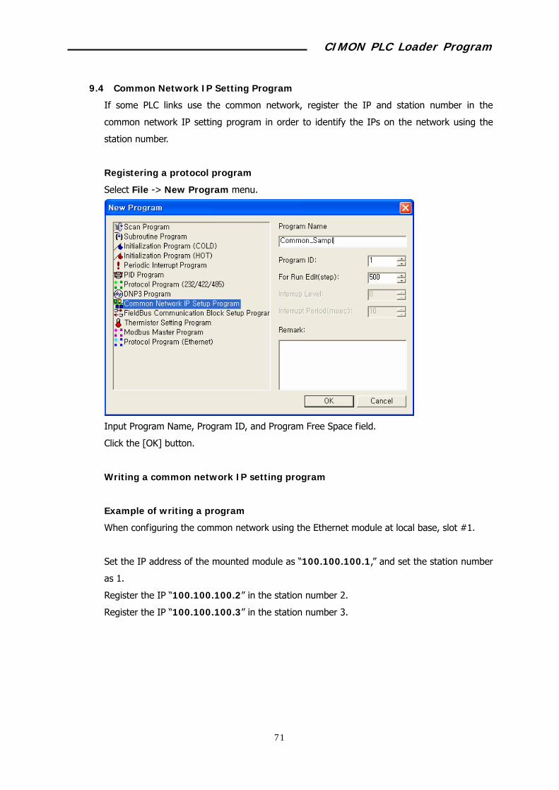
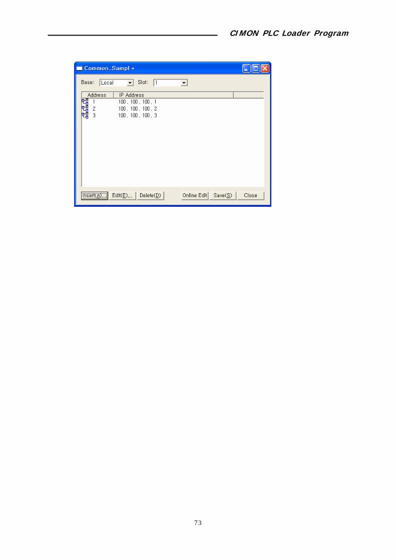
9.4 Common Network IP Setting Program
If some PLC links use the common network, register the IP and station number in the
common network IP setting program in order to identify the IPs on the network using the
station number.
Registering a protocol program
Select File -> New Program menu.
Input Program Name, Program ID, and Program Free Space field.
Click the [OK] button.
Writing a common network IP setting program
Example of writing a program
When configuring the common network using the Ethernet module at local base, slot #1.
Set the IP address of the mounted module as “100.100.100.1,” and set the station number
as 1.
Register the IP “100.100.100.2” in the station number 2.
Register the IP “100.100.100.3” in the station number 3.

CIMON PLC Loader Program
94
Click the [Insert] button to display the “Add IP” window.
Select the station number (1) in the “Add IP” window, and input the IP address
(100.100.100.1) and then, press the [Enter] key.
Register the station number 2 and 3 using the same method.
CIMON PLC Loader Program
95

CIMON PLC Loader Program
96
9.5 Field Bus Communication Block Setup Program
When controlling the remote I/O using the internal PLC device in the Profibus DP or
DeviceNet Master module, set the I/O area using the field bus communication block setting
program.
Registering a protocol program
Select File -> New Program menu.
Input Program Name, Program ID, and Program Free Space field.
Click the [OK] button.
Writing a field bus communication block setting program
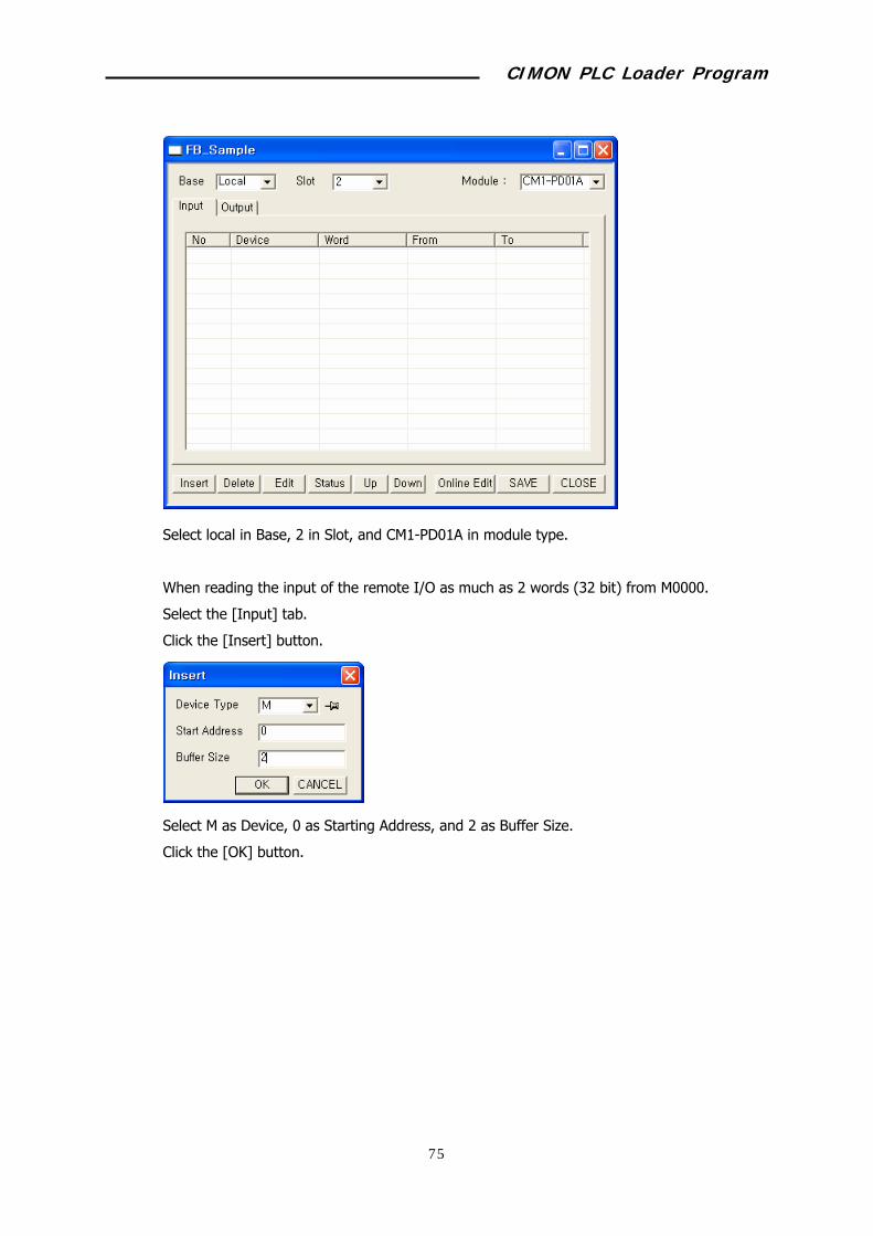
Example of writing a program
When controlling the remote I/O using the filed bus (PD01A: Profibus DP) master module at
local base, slot #2, the number of remote I/O connected to the field bus master is 32 point
inputs and 16 point outputs.
CIMON PLC Loader Program
97
Select local in Base, 2 in Slot, and CM1-PD01A in module type.
When reading the input of the remote I/O as much as 2 words (32 bit) from M0000.
Select the [Input] tab.
Click the [Insert] button.
Select M as Device, 0 as Starting Address, and 2 as Buffer Size.
Click the [OK] button.

CIMON PLC Loader Program
98
When setting 1 word (16 bit) data from Y0010 as the output of the remote I/O.
Select the [Output] tab.
Click the [Insert] button.
Select Y as Device, 10 as Starting Address, and 1 as Buffer Size.
Click the [OK] button.

CIMON PLC Loader Program
99

CIMON PLC Loader Program
100
9.6 Thermistor Setting Program
CIMON PLC Loader Program
101
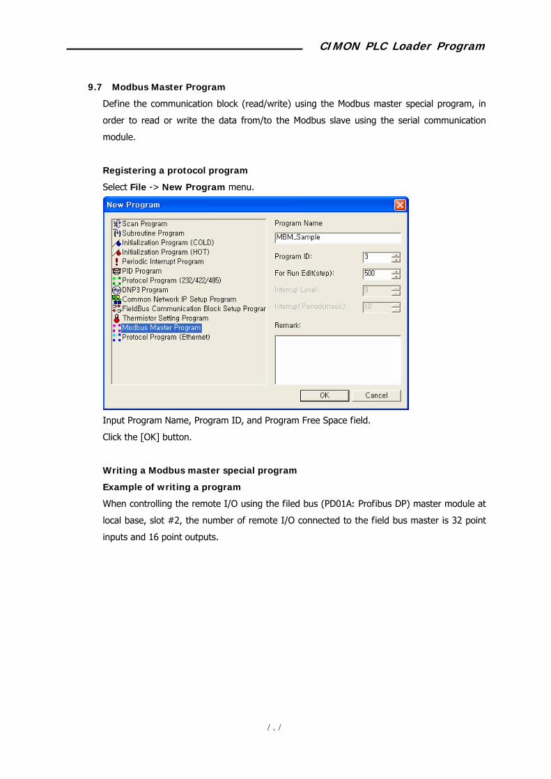
9.7 Modbus Master Program
Define the communication block (read/write) using the Modbus master special program, in
order to read or write the data from/to the Modbus slave using the serial communication
module.
Registering a protocol program
Select File -> New Program menu.
Input Program Name, Program ID, and Program Free Space field.
Click the [OK] button.
Writing a Modbus master special program
Example of writing a program
When controlling the remote I/O using the filed bus (PD01A: Profibus DP) master module at
local base, slot #2, the number of remote I/O connected to the field bus master is 32 point
inputs and 16 point outputs.
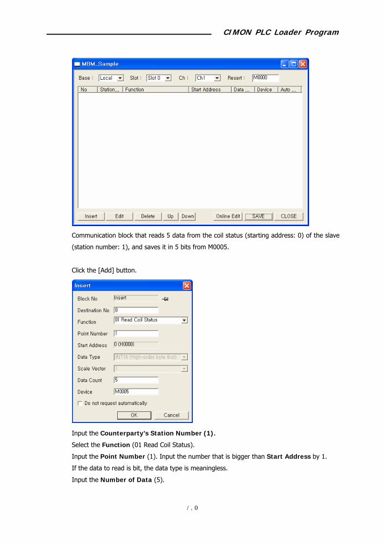
CIMON PLC Loader Program
102
Communication block that reads 5 data from the coil status (starting address: 0) of the slave
(station number: 1), and saves it in 5 bits from M0005.
Click the [Add] button.
Input the Counterparty’s Station Number (1).
Select the Function (01 Read Coil Status).
Input the Point Number (1). Input the number that is bigger than Start Address by 1.
If the data to read is bit, the data type is meaningless.
Input the Number of Data (5).

CIMON PLC Loader Program
103
Input the Device (M0005).
If you don’t select “Do not request automatically” option, the communication block will
be automatically processed.
Click the [OK] button.
Communication block that writes 4 words from D00000 at the signal register (starting
address: 0) of the slave (station number: 1).
Click the [Add] button.
Input the Destination No (1).
Select the Function (06 Preset Single Register).
Input the Point Number (1). Input the number that is bigger than Start Address by 0.
Select the Data Type (INT16:High order byte first).
Input the Data Count (1).
Input the Device (D00000).
If you don’t select “Do not request automatically” option, the communication block will
be automatically processed.
Click the [OK] button.
CIMON PLC Loader Program
104
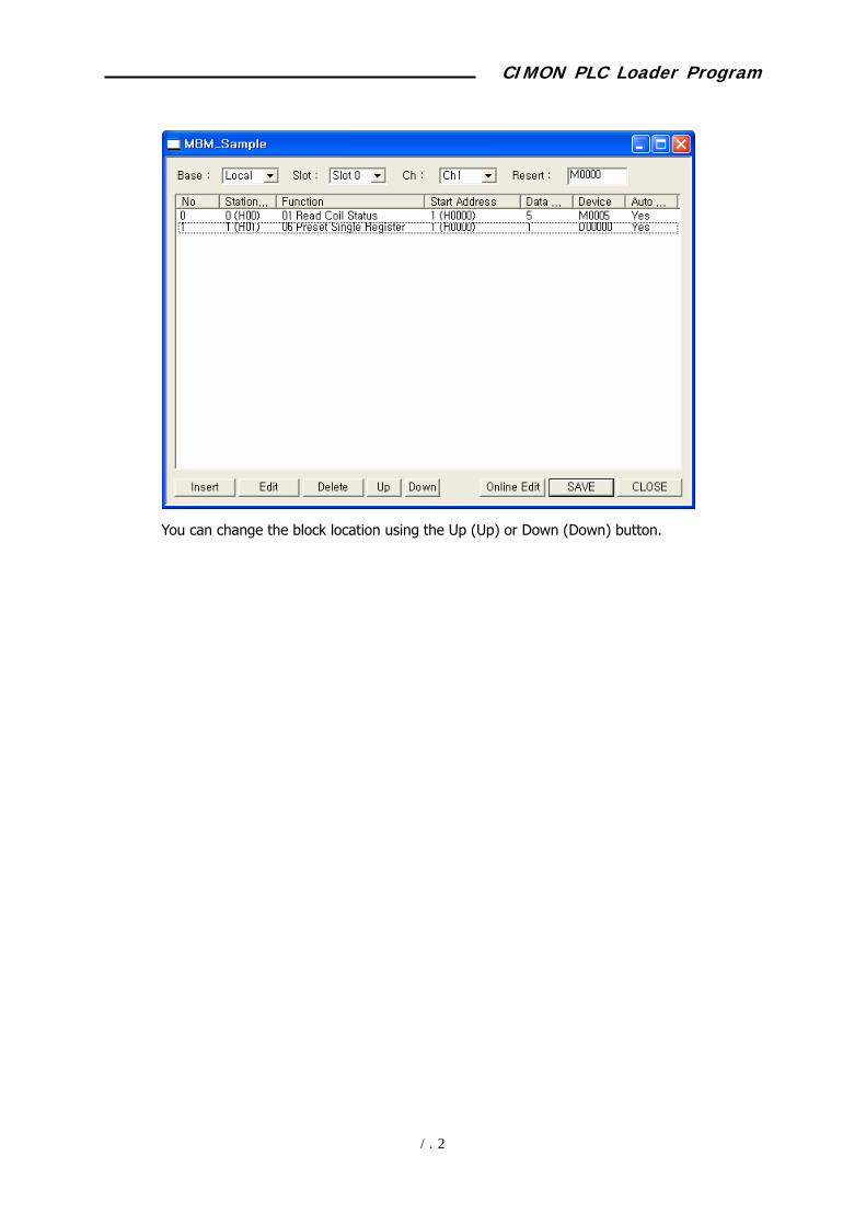
You can change the block location using the Up (Up) or Down (Down) button.
CIMON PLC Loader Program
105
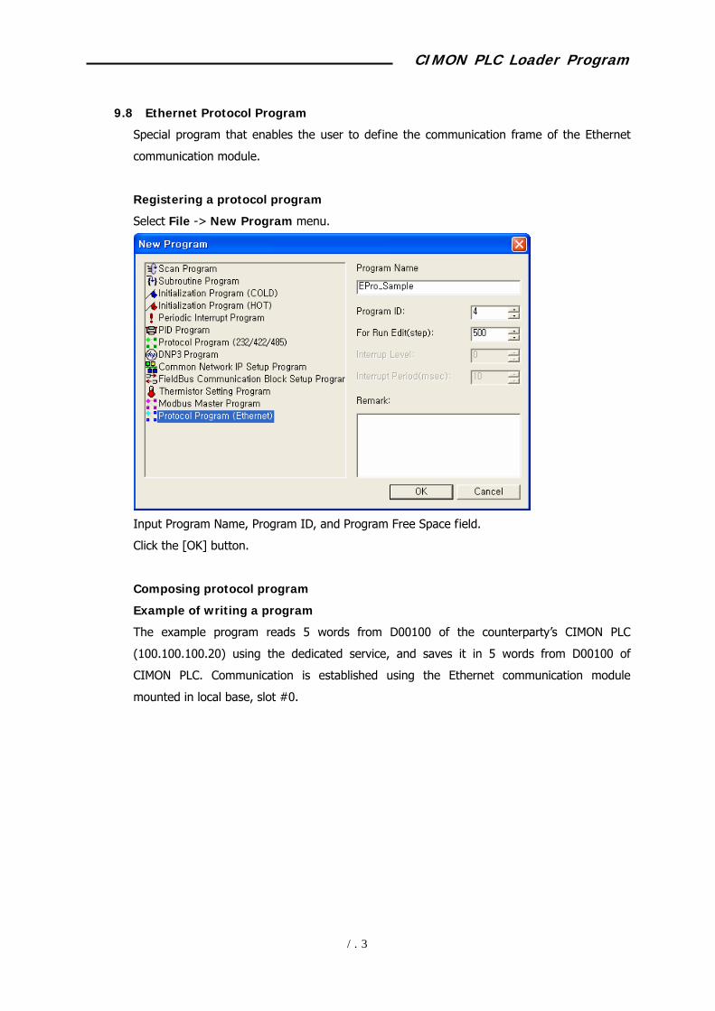
9.8 Ethernet Protocol Program
Special program that enables the user to define the communication frame of the Ethernet
communication module.
Registering a protocol program
Select File -> New Program menu.
Input Program Name, Program ID, and Program Free Space field.
Click the [OK] button.
Composing protocol program
Example of writing a program
The example program reads 5 words from D00100 of the counterparty’s CIMON PLC
(100.100.100.20) using the dedicated service, and saves it in 5 words from D00100 of
CIMON PLC. Communication is established using the Ethernet communication module
mounted in local base, slot #0.

CIMON PLC Loader Program
106
Registering a host
Registers the PLC Ethernet card to read the data.
Click the [Add Host] button.
Input the device (M0000) to save the Communication Result.
Input the counterparty’s IP (100.100.100.20).
Input the Port Number (10262) to use for communication. The port number in the dedicated
CIMON PLC Loader Program
107
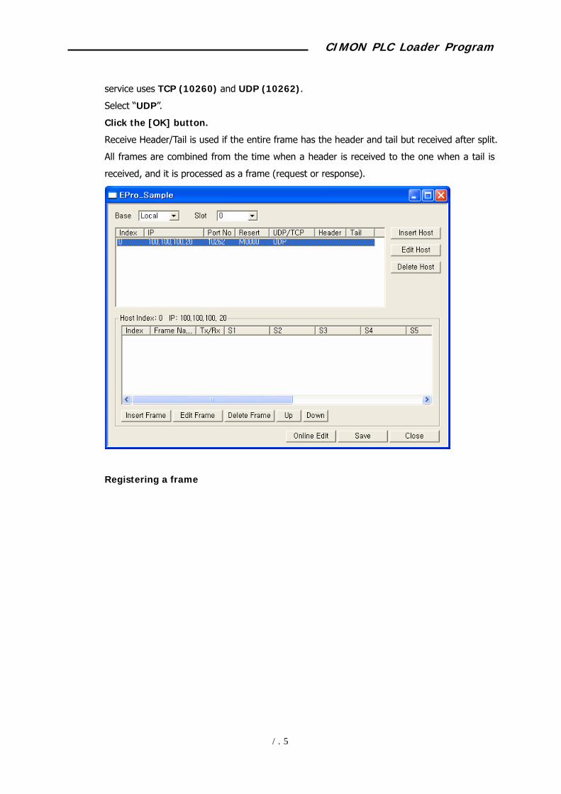
service uses TCP (10260) and UDP (10262).
Select “UDP”.
Click the [OK] button.
Receive Header/Tail is used if the entire frame has the header and tail but received after split.
All frames are combined from the time when a header is received to the one when a tail is
received, and it is processed as a frame (request or response).
Registering a frame

CIMON PLC Loader Program
108
Select a host and click the [Add Frame] button, the Define Frame window will appear.
Input the setting items.
Frame name: Name to separate the frame.
Tx/Rx: Sets the communication direction – sending or receiving.
Auto Send/Receive: Sending frames will be automatically sent at the specified interval.
Ts. Of Auto Send: Specifies the frame that corresponds to the response.
Functions related with segment editing
Insert: Defines and adds a new segment.
Edit: Edits the registered segment details.
Defining a frame (Rx frame for the Word Block Read command)
Defines the frame contents to interpret the response frame against the Word Block Read
request frame of CIMON PLC.
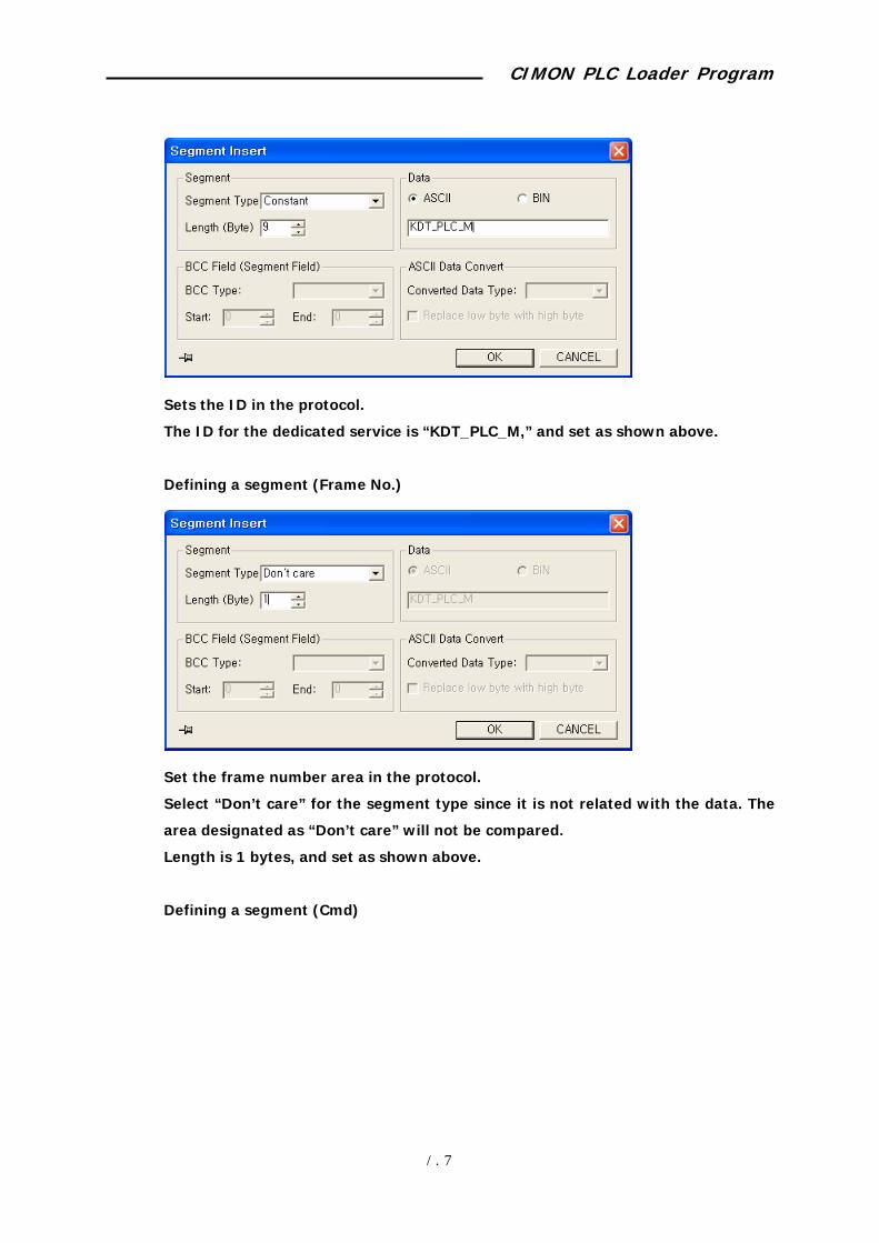
Defining a segment (ID)
CIMON PLC Loader Program
109
Sets the ID in the protocol.
The ID for the dedicated service is “KDT_PLC_M,” and set as shown above.
Defining a segment (Frame No.)
Set the frame number area in the protocol.
Select “Don’t care” for the segment type since it is not related with the data. The
area designated as “Don’t care” will not be compared.
Length is 1 bytes, and set as shown above.
Defining a segment (Cmd)
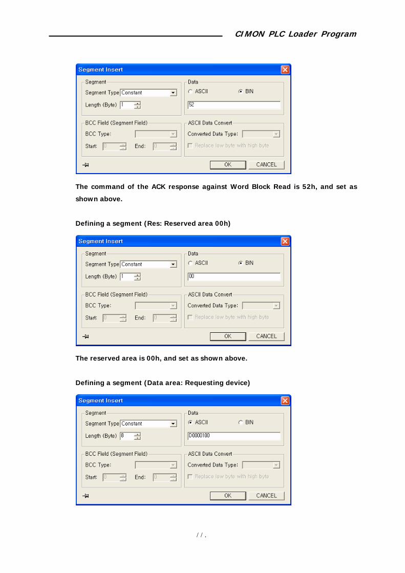
CIMON PLC Loader Program
110
The command of the ACK response against Word Block Read is 52h, and set as
shown above.
Defining a segment (Res: Reserved area 00h)
The reserved area is 00h, and set as shown above.
Defining a segment (Data area: Requesting device)
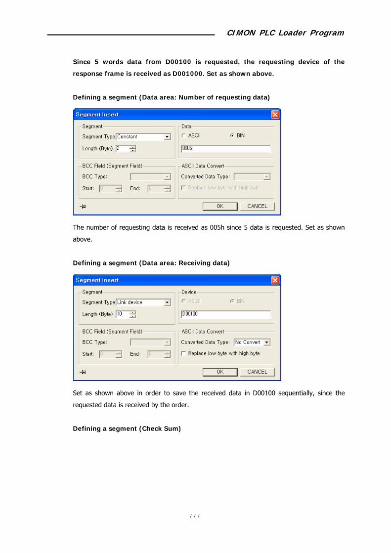
CIMON PLC Loader Program
111
Since 5 words data from D00100 is requested, the requesting device of the
response frame is received as D001000. Set as shown above.
Defining a segment (Data area: Number of requesting data)
The number of requesting data is received as 005h since 5 data is requested. Set as shown
above.
Defining a segment (Data area: Receiving data)
Set as shown above in order to save the received data in D00100 sequentially, since the
requested data is received by the order.
Defining a segment (Check Sum)

CIMON PLC Loader Program
112
The checksum area is the entire frame area, and set as shown above.
Finishing defining a frame (Rx frame for Word Block Read)
The communication direction is the receiving frame, and set as shown above.
Defining a frame (Word Block Read Tx frame)
Defines the request frame for Word Block Read.
Defining a segment (ID)

CIMON PLC Loader Program
113
Sets the ID in the protocol.
The ID for the dedicated service is “KDT_PLC_M,” and set as shown above.
Defining a segment (Frame No.)
Set the frame number area in the protocol.
Length is 1 bytes, and set as shown above.
Defining a segment (Cmd)

CIMON PLC Loader Program
114
The command of the ACK response against Word Block Read is 52h, and set as
shown above
Defining a segment (Res: Reserved area 00h)
The reserved area is 00h, and set as shown above.
Defining a segment (Data area: Requesting device)

CIMON PLC Loader Program
115
Since 5 words data from D00100 is requested, the requesting device of the
response frame is received as D001000. Set as shown above.
Defining a segment (Data area: Number of requesting data)
The number of requesting data is received as 005h since 5 data is requested. Set as shown
above.
Defining a segment (Check Sum)
The checksum area is the entire frame area, and set as shown above.
Finishing frame registration (Tx frame for Word Block Read)
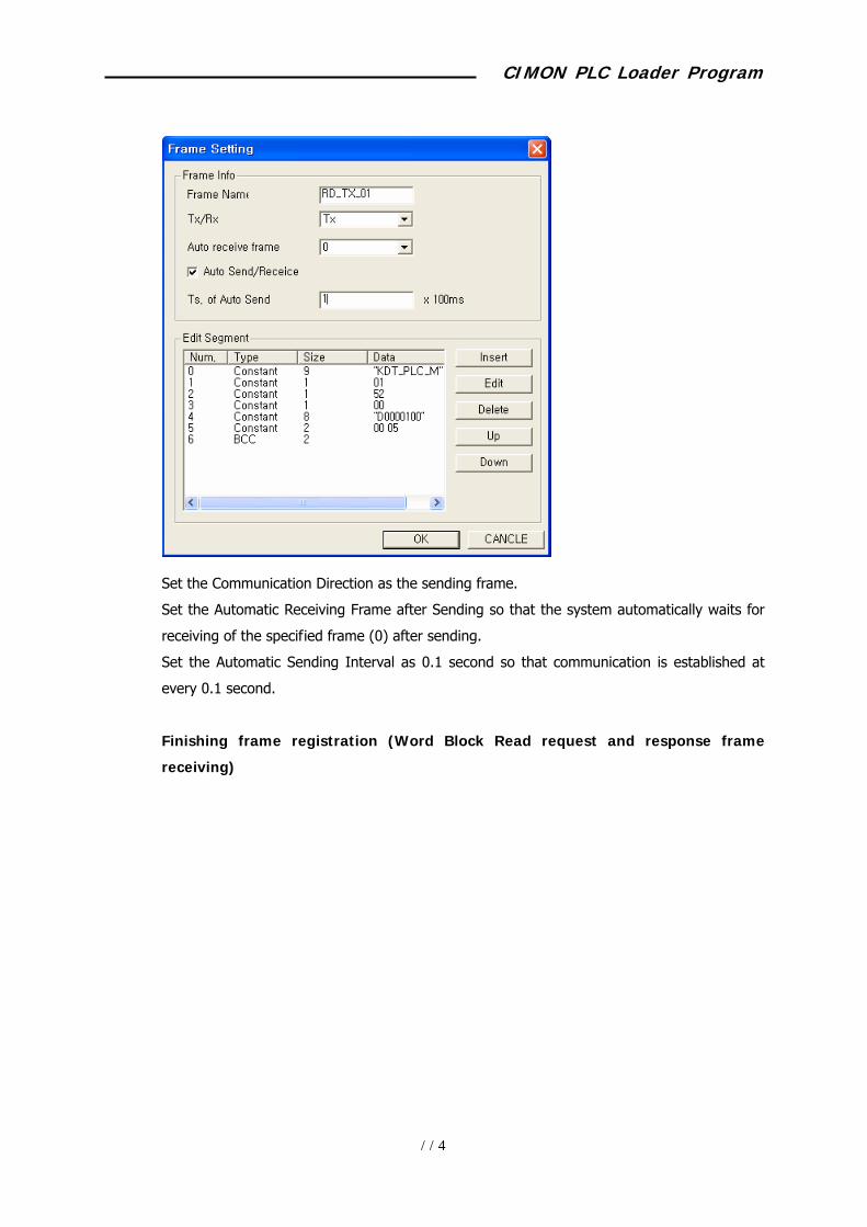
CIMON PLC Loader Program
116
Set the Communication Direction as the sending frame.
Set the Automatic Receiving Frame after Sending so that the system automatically waits for
receiving of the specified frame (0) after sending.
Set the Automatic Sending Interval as 0.1 second so that communication is established at
every 0.1 second.
Finishing frame registration (Word Block Read request and response frame
receiving)
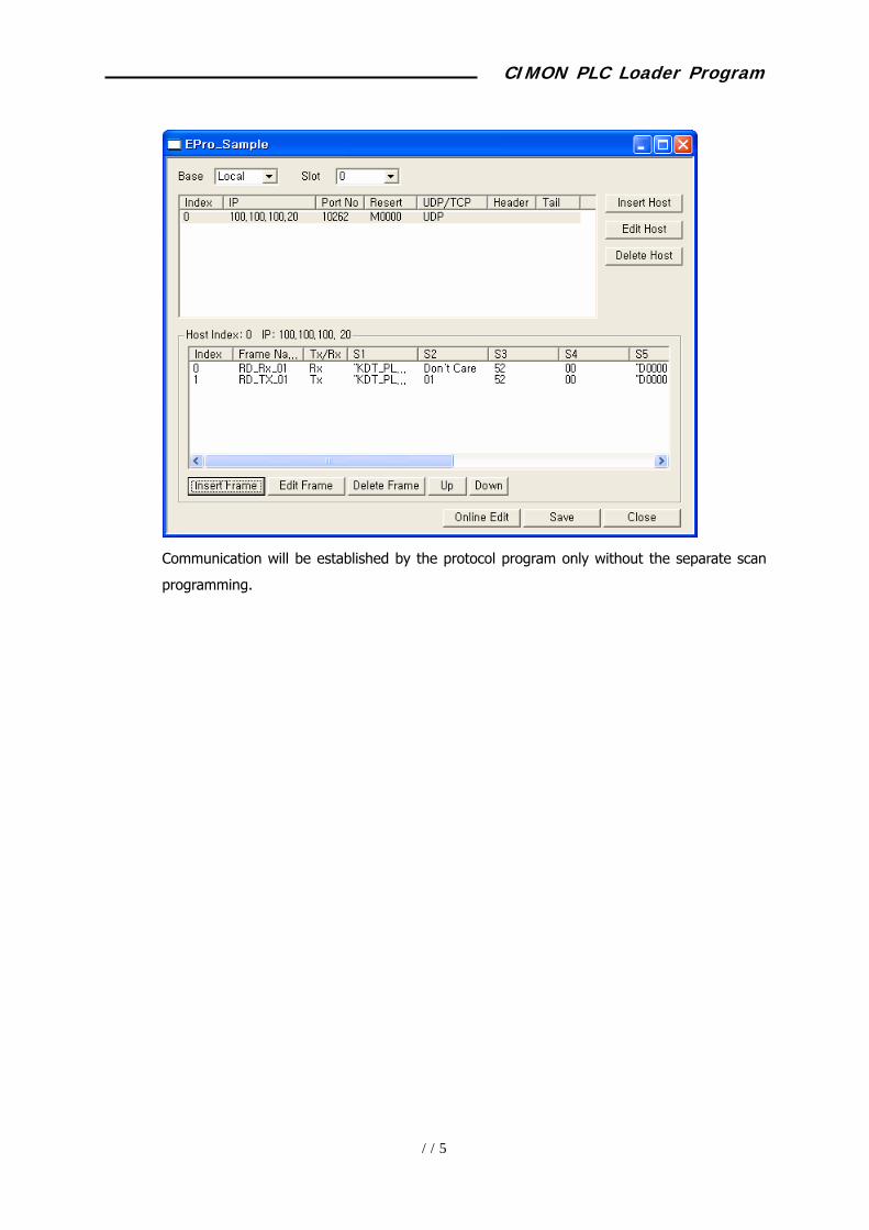
CIMON PLC Loader Program
117
Communication will be established by the protocol program only without the separate scan
programming.
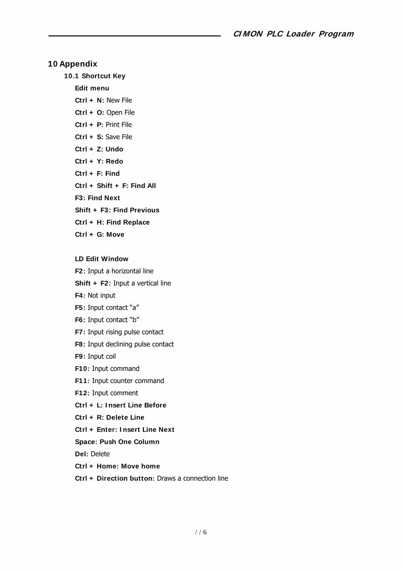
CIMON PLC Loader Program
118
10 Appendix 10.1 Shortcut Key
Edit menu
Ctrl + N: New File
Ctrl + O: Open File
Ctrl + P: Print File
Ctrl + S: Save File
Ctrl + Z: Undo
Ctrl + Y: Redo
Ctrl + F: Find
Ctrl + Shift + F: Find All
F3: Find Next
Shift + F3: Find Previous
Ctrl + H: Find Replace
Ctrl + G: Move
LD Edit Window
F2: Input a horizontal line
Shift + F2: Input a vertical line
F4: Not input
F5: Input contact “a”
F6: Input contact “b”
F7: Input rising pulse contact
F8: Input declining pulse contact
F9: Input coil
F10: Input command
F11: Input counter command
F12: Input comment
Ctrl + L: Insert Line Before
Ctrl + R: Delete Line
Ctrl + Enter: Insert Line Next
Space: Push One Column
Del: Delete
Ctrl + Home: Move home
Ctrl + Direction button: Draws a connection line

CIMON PLC Loader Program
119
10.2 Loader Cabling Diagram
Description on DSUB-9 pins
2: Rx
3: Tx
5: SG
Description on RJ-11 pins
2: Tx
3: Rx
5: SG