Embed Size (px)
Citation preview
Cibolo
Water & Sanitary Sewer Standards & Technical
Specifications
INTRODUCTION
THE STANDARD SPECIFICATIONS AND DRAWINGS ARE PROVIDED AS A TECHNICAL RESOURCE FOR ENGINEERING PROFESSIONALS FOR USE IN DESIGN AND CONSTRUCTION OF WATER AND WASTEWATER PROJECTS MANAGED AND CONTRACTED BY THE CITY OF CIBOLO. AS DESIGN PROFESSIONALS, THEY ASSUME RESPONSIBLITY FOR SELECTION, REFERENCE, AND APPROPRIATE APPLICATION OF THESE RESOURCES. THE STANDARD SPECIFICATIONS AND STANDARD DRAWINGS OFFERED HERE CAN BE AUGMENTED BY SUPPLEMENTAL SPECIFICATIONS AND MODIFIED DETAILS PRODUCED BY THE ASSIGNED OR CONTRACTED DESIGN PROFESSIONAL AND APPROVED BY THE CITY OF CIBOLO. THE CITY OF CIBOLO ACCEPTS NO LIABILITY FOR USE OF THESE RESOURCES. ANY PERSON MAKING USE OF THE INFORMATION CONTAINED IN THESE FILES SHALL BE SOLELY RESPONSIBLE FOR THEIR USE. THESE FILES ARE NOT INTENDED AS A SUBSTITUTE FOR THE PROFESSIONAL JUDGEMENT OF A DESIGN PROFESSIONAL.
AT ANY TIME, THESE SPECIFICATIONS AND DRAWINGS MAY BE ALTERED OR SUPERSEDED BY THE GENERAL CONDITIONS, SPECIFIC CONDITIONS, OR DRAWINGS WITHIN THE CONSTRUCTION PLANS FOR EACH PROJECT. THE CITY OF CIBOLO ACKNOWLEDGES THAT THE SAN ANTONIO WATER SYSTEM (SAWS) IS RECOGNIZED AS THE STATE AND NATIONAL LEADER IN WATER AND WASTE WATER SYSTEM DESIGN AND CONSTRUCTION. FOR THAT REASON, SINCE 2009 THE CITY OF CIBOLO HAS USED THESE STANDARDS, WITH LOCAL AMENDMENTS, AS THE BASIS FOR DEVELOPING THE CITY OF CIBOLO WATER AND WASTEWATER SYSTEMS. AS SUCH, THE STANDARDS CONTAINED HEREIN ARE BASED ON THE 2009 SAWS STANDARDS, WITH LOCAL AMENDMENTS NOTED, AND REFERENCES MADE TO THE CITY OF CIBOLO. WITH RESPECT TO “APPROVED” MATERIAL SPECIFICATION LIST AND NUMBERS, THIS MANUAL INTENTIONALLY REFERS TO THE SAWS APPROVED MATERIAL LIST AND NUMBERS TO AVOID CONFUSION AND MAINTAIN CONSISTENCY WITH WIDELY USED REGIONAL TERMINOLOGY. WHEN AND IF SAWS AMENDS THEIR LIST, THIS MANUAL WILL AUTMATICALLY BE AMENDED TO REFERNCE THE UPDATES MADE BY SAWS. ANY MATERIAL THAT SAWS SPECIFICALLY SHALL PROHIBIT, OR ALLOW, SHALL BE INCORPORATED BY REFERENCE INTO THIS MANUAL.
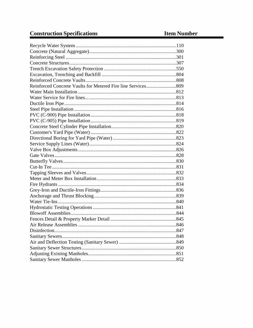
Construction Specifications Item Number
Recycle Water System .................................................................................110 Concrete (Natural Aggregate)......................................................................300 Reinforcing Steel .........................................................................................301 Concrete Structures ......................................................................................307 Trench Excavation Safety Protection ..........................................................550 Excavation, Trenching and Backfill ............................................................804 Reinforced Concrete Vaults .........................................................................808 Reinforced Concrete Vaults for Metered Fire line Services........................809 Water Main Installation ...............................................................................812 Water Service for Fire lines... ......................................................................813 Ductile Iron Pipe ..........................................................................................814 Steel Pipe Installation ..................................................................................816 PVC (C-900) Pipe Installation .....................................................................818 PVC (C-905) Pipe Installation .....................................................................819 Concrete Steel Cylinder Pipe Installation ....................................................820 Customer's Yard Pipe (Water) .....................................................................822 Directional Boring for Yard Pipe (Water) ...................................................823 Service Supply Lines (Water) ......................................................................824 Valve Box Adjustments ...............................................................................826 Gate Valves ..................................................................................................828 Butterfly Valves ...........................................................................................830 Cut-In Tee ....................................................................................................831 Tapping Sleeves and Valves ........................................................................832 Meter and Meter Box Installation ................................................................833 Fire Hydrants ...............................................................................................834 Grey-Iron and Ductile-Iron Fittings.............................................................836 Anchorage and Thrust Blocking ..................................................................839 Water Tie-Ins ...............................................................................................840 Hydrostatic Testing Operations ...................................................................841 Blowoff Assemblies .....................................................................................844 Fences Detail & Property Marker Detail .....................................................845 Air Release Assemblies ...............................................................................846 Disinfection..................................................................................................847 Sanitary Sewers............................................................................................848 Air and Deflection Testing (Sanitary Sewer) ..............................................849 Sanitary Sewer Structures ............................................................................850 Adjusting Existing Manholes.......................................................................851 Sanitary Sewer Manholes ............................................................................852
Reinforced Polyester Manholes ...................................................................853 Sanitary Sewer Laterals ...............................................................................854 Reconstruction of Existing Manholes ..........................................................855 Jacking, Boring or Tunneling Pipe ..............................................................856 Concrete Encasement, Cradles, Saddles, and Collars..................................858 Vertical Stacks .............................................................................................860 Abandonment of Sewer Mains and Manholes .............................................862 Bypass Pumping...........................................................................................864 Sewer Main Television Inspection ..............................................................866 Sewer Main Cleaning...................................................................................868 Project Signs ................................................................................................869 Pipe Bursting/Crushing Replacement Process.............................................900 Water Main Breaks/Leak Repairs ................................................................1020 Slip-Lining Sanitary Sewers ........................................................................1100 Project Record Documents ..........................................................................1112 Pre-Construction Videos ..............................................................................1114 High Pressure Distribution System..............................................................HP-1

ITEM NO. 110 RECYCLE WATER SYSTEM
110.1 DESCRIPTION: Any work done on the existing or proposed recycled water
distribution system shall be accomplished with the, C i t y o f C i b o l o Standard Specifications for Water, except as otherwise noted. All proposed construction plans and drawings must be reviewed and approved for compliance with the City of Cibolo backflow prevention standards prior to start of work.
110.2 MATERIAL: All material used in the improvement and/or construction of
recycled water shall meet City of Cibolo Standard Specifications for Water requirements and standards (i.e. uses of CSC pipe, trenching and excavation, etc…), except as otherwise noted, and must be wrapped or painted with pantone 512 color.
110.3 INSTALLATION: The installation of any recycle water main(s) shall be done in
accordance with the City of Cibolo Standard Specifications for Water, except as otherwise noted. Recycle mains shall also be installed with the TCEQ required separation distance between sewer and/or water mains as required by Texas Administrative Code (TAC) rules to include: 30 TAC § Chapters 210, 290, & 217.
ITEM NO. 300 CONCRETE (NATURAL AGGREGATE)
300.1 DESCRIPTION: This item shall govern the material used; storing and handling
of materials; and the proportioning, mixing and transportation of concrete for all concrete construction.
This specification does not cover the placement, consolidation, curing, or protection of the concrete.
300.2 MATERIAL: The concrete shall be composed of Portland Cement, mineral
filler, if necessary, natural aggregates (fine and coarse), and water, proportioned and mixed as hereinafter provided in these specifications. Concrete shall meet all the requirements as set forth in ASTM C-94.
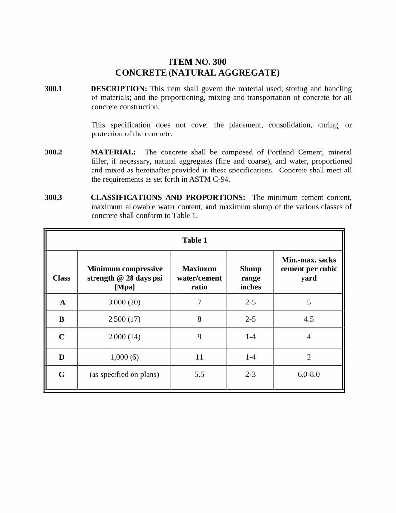
300.3 CLASSIFICATIONS AND PROPORTIONS: The minimum cement content,
maximum allowable water content, and maximum slump of the various classes of concrete shall conform to Table 1.
Table 1
Class
Minimum compressive strength @ 28 days psi
[Mpa]
Maximum water/cement
ratio
Slump range inches
Min.-max. sacks cement per cubic
yard
A
3,000 (20)
7
2-5
5
B
2,500 (17)
8
2-5
4.5
C
2,000 (14)
9
1-4
4
D
1,000 (6)
11
1-4
2
G
(as specified on plans)
5.5
2-3
6.0-8.0
ITEM NO. 301 REINFORCING STEEL
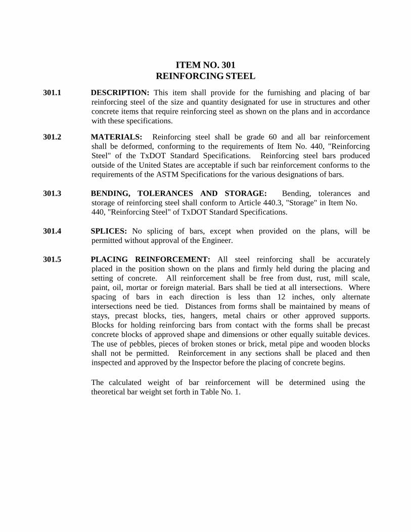
301.1 DESCRIPTION: This item shall provide for the furnishing and placing of bar
reinforcing steel of the size and quantity designated for use in structures and other concrete items that require reinforcing steel as shown on the plans and in accordance with these specifications.
301.2 MATERIALS: Reinforcing steel shall be grade 60 and all bar reinforcement
shall be deformed, conforming to the requirements of Item No. 440, "Reinforcing Steel" of the TxDOT Standard Specifications. Reinforcing steel bars produced outside of the United States are acceptable if such bar reinforcement conforms to the requirements of the ASTM Specifications for the various designations of bars.
301.3 BENDING, TOLERANCES AND STORAGE: Bending, tolerances and storage of reinforcing steel shall conform to Article 440.3, "Storage" in Item No. 440, "Reinforcing Steel" of TxDOT Standard Specifications.
301.4 SPLICES: No splicing of bars, except when provided on the plans, will be
permitted without approval of the Engineer. 301.5 PLACING REINFORCEMENT: All steel reinforcing shall be accurately
placed in the position shown on the plans and firmly held during the placing and setting of concrete. All reinforcement shall be free from dust, rust, mill scale, paint, oil, mortar or foreign material. Bars shall be tied at all intersections. Where spacing of bars in each direction is less than 12 inches, only alternate intersections need be tied. Distances from forms shall be maintained by means of stays, precast blocks, ties, hangers, metal chairs or other approved supports. Blocks for holding reinforcing bars from contact with the forms shall be precast concrete blocks of approved shape and dimensions or other equally suitable devices. The use of pebbles, pieces of broken stones or brick, metal pipe and wooden blocks shall not be permitted. Reinforcement in any sections shall be placed and then inspected and approved by the Inspector before the placing of concrete begins.
The calculated weight of bar reinforcement will be determined using the theoretical bar weight set forth in Table No. 1.
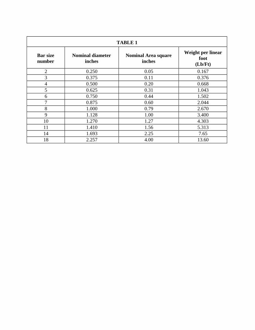
TABLE 1
Bar size number
Nominal diameter
inches
Nominal Area square
inches
Weight per linear foot
(Lb/Ft) 2 0.250 0.05 0.167 3 0.375 0.11 0.376 4 0.500 0.20 0.668 5 0.625 0.31 1.043 6 0.750 0.44 1.502 7 0.875 0.60 2.044 8 1.000 0.79 2.670 9 1.128 1.00 3.400 10 1.270 1.27 4.303 11 1.410 1.56 5.313 14 1.693 2.25 7.65 18 2.257 4.00 13.60
ITEM NO. 307 CONCRETE STRUCTURES
307.1 DESCRIPTION: This item shall govern the construction of box culverts, headwalls, wingwalls, bridges, box transitions, approach slabs, retaining walls, inlets, storm sewer structures, sanitary sewer structures and incidental structures. All concrete structures shall be constructed in accordance with specifications herein outlined and in conformity with the required lines, grades, sections and details shown on the plans or as directed by the Engineer.
307.2 MATERIALS:
1. Concrete: All concrete shall conform to the provisions of Item No. 300, "Concrete (Class A)" or shall be of a class as noted on the plans.
2. Reinforcing Steel: All reinforcing steel shall conform to the provisions of Item No. 301, "Reinforcing Steel."
3. Membrane Curing Compound: All membrane curing compound shall conform to the provisions of Item No. 305, "Membrane Curing."
4. Expansion Joint Materials: All expansion joint materials shall conform to the provisions of Item No. 304, "Expansion Joint Materials."
5. Cast Iron Castings: All cast iron castings shall conform to the provisions of Item No. 409, "Cast Iron Castings."
6. Metal for Structures: Metal for structures shall conform to the provisions of Item No. 302, "Metal for Structures."
307.3 CONSTRUCTION METHODS:
1. Forms: Forms shall be of wood, metal or other approved materials and shall conform to the following requirements:
a. Wood Forms:
(1) Unexposed concrete surfaces, No. 2 common or better lumber.
(2) Exposed concrete surfaces, dressed and matched boards of uniform thickness and width.
b. Plywood: Commercial Standard Douglas Fir, moisture resistant, concrete form plywood, not less than 5 ply and at least 9/16th of an inch in thickness. The face of the plywood shall be free from knot
holes and other blemishes.
c. Metal Forms: Metal forms of an approved type that will produce surfaces equal to or better than those specified for wood forms.
Forms may be constructed of any of the above substances or of other material if suited to the intended purpose and when approved by the Inspector. Forms shall be built mortar tight and of sufficient strength to prevent bulging between supports and shall be set and maintained to the line and grade designated until the concrete is sufficiently hardened to permit removal. All details of form construction shall be subject to the approval of the Inspector and, in special cases, the approval of the Engineer may be required. Permission to place concrete will not be given by the Inspector until all form work has been placed in accordance with the above requirements. If at any stage of the work, the forms show signs of bulging, sagging or moving, that portion of the concrete causing such conditions shall be immediately removed, if required by the Inspector, and the forms reset and securely braced against further movement.
All corners and edges, which will be exposed after construction, shall be chamfered with triangular chamfer strips ¾ inch measured on the sides.
2. Placing Reinforcement: All steel reinforcement shall be placed in
accordance with Item No. 301, "Reinforcing Steel."
3. Placing Concrete: The base slabs of inlets, junction boxes, headwalls, culverts and other structures shall be placed and allowed to set before the remainder of the structure is constructed. Suitable provisions shall be made for bonding the sidewalls to the base slab by means of longitudinal keys so constructed as to prevent the percolation of water through the construction joints. Before concrete is placed in the walls, the keyed-edge joints shall be thoroughly cleaned of all shavings, sticks, trash or other extraneous materials. The top slabs of culverts and like structures may be poured monolithic with the walls, provided the walls are poured and allowed to set a minimum of 1 hour, no more than 2 hours, shall elapse between the placing of the concrete in the wall and that in the top slab; such interval is to allow for shrinkage of the concrete in the wall. Under adverse weather conditions, the minimum time will be increased by the Inspector. All concrete shall be placed with the aid of mechanical vibrating equipment supplemented inside the forms. Vibrating equipment shall be of the internal type and shall maintain a speed of 6,000 impulses per minute, when submerged in concrete. Vibrators shall be adequate in number of units
to properly consolidate all concrete. Form or surface vibrators shall not be used. The duration of vibration shall be limited to properly consolidate the concrete without causing objectionable segregation of aggregates. Insertion of vibrators into lower courses that have commenced initial set, or the disturbance or reinforcement in concrete beginning to set, shall be avoided.
Concrete shall not be allowed to drop freely more than 5 feet in unexposed work, nor more than 3 feet in exposed work; where greater drops are required, a tremie or other approved means shall be employed. Concrete shall not be placed when the ambient temperature is below 40° F, nor where the concrete is likely to be subject to freezing before final set has occurred. When the air temperature is expected to drop below 40° F during the first 72 hours of the curing period, polyethylene sheeting or burlap-polyethylene blankets shall be placed in direct contact with the top surface of the concrete. Concrete may be poured in temperatures below 40° F, when poured in protected areas, or where adequate protection can be provided against freezing, if approved by the Inspector. When concrete is poured in air temperatures above 85° F, an approved retarding agent, meeting the requirements of ASTM C494, Type B, will be required in all concrete used in superstructures and top slabs of culverts unless directed otherwise by the Inspector.
4. Form Removal: Forms shall be removed only with the approval of the
Inspector and in a manner to insure complete safety of the structure when the structure as a whole is supported on shoring. Form removal from structures shall not begin until the concrete has attained the following compressive strengths:
a. Vertical forms shall not be removed until the concrete has set a
minimum of 24 hours, or the concrete has attained a minimum compressive strength of 500 psi.
b. When wall and top slabs are poured monolithically, wall forms
shall not be removed until the concrete has attained a minimum compressive strength of 2000 psi.
5. Finish: Honeycomb and other minor defects shall be patched with one part of cement to 2 parts fine aggregate. All exposed surfaces shall be given one of the following finishes:
a. Rough Finish: Concrete for which no other finish is indicated or
specified shall have fins and rough edges removed.
b. Smooth Finish: Smooth finish shall be given to the interior of inlets, junction boxes, culverts and other structures. Joint marks, fins and rough edges shall be smoothed off and blemishes removed, leaving
finished surfaces smooth and unmarred, subject to approval by the Inspector.
c. Floor Finish: Floor finish shall be given to the floors of all inlets,
culverts and other structures, and shall be struck off true to the required grade as shown on the drawings and floated to a smooth, even finish by manual or mechanical methods. No coarse aggregate shall be visible after finishing.
d. Rubbed Finish: All exposed surfaces of retaining walls, wingwalls,
headwalls and other structures, after patching and painting has been completed and the surface has been wetted, shall be given a first rubbing with a No. 16 Carborundum Stone. After the first rubbing is completed and the ground material has been evenly spread, the material shall be allowed to take a reset. After sufficient aging, the surface shall be wetted and given a finish rubbing with a No. 30 Carborundum Stone, after which the surface shall be neatly striped with a brush and allowed to take a reset. On the inside surfaces of all culvert walls an area from the top slab, on a line 30 degrees from the vertical, to the bottom slab shall be rubbed as specified above.
The entire structure shall be left with a clear, neat, uniform finish, free from form markings and shall be uniform in color.
e. Sidewalk surfaces shall be given a wood float finish, a light broom
finish, or may be stripped with a brush as directed by the Inspector or specified in the plans.
f. Roadway slabs shall be given a broom finish after completion of the
floating or straight-edging operation, but before the disappearance of the moisture sheen. The grooves of the finish shall be parallel to the centerline of the roadway. The average texture depth of the grooves shall be a minimum of 0.035 inches.
The Contractor has the option of substituting the surface finish described in Item No. 311, "Special Concrete Surface Finish" on the surface areas listed in the specification.
6. Curing: Immediately after placing or finishing, concrete surfaces not
covered by forms shall be protected from loss of surface moisture for not less than 4 curing days. When forms are left in place, they shall be kept sufficiently wet to reduce cracks in the forms and prevent the form joints from opening. If forms are removed before 4 curing days have transpired, the formed surface shall be protected for the remainder of the 4 day curing period. Protection and curing shall be accomplished by one of the
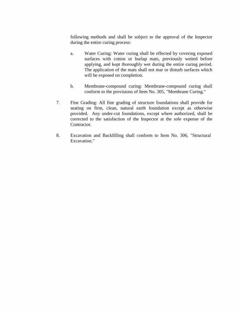
following methods and shall be subject to the approval of the Inspector during the entire curing process:
a. Water Curing: Water curing shall be effected by covering exposed
surfaces with cotton or burlap mats, previously wetted before applying, and kept thoroughly wet during the entire curing period. The application of the mats shall not mar or disturb surfaces which will be exposed on completion.
b. Membrane-compound curing: Membrane-compound curing shall
conform to the provisions of Item No. 305, "Membrane Curing."
7. Fine Grading: All fine grading of structure foundations shall provide for seating on firm, clean, natural earth foundation except as otherwise provided. Any under-cut foundations, except where authorized, shall be corrected to the satisfaction of the Inspector at the sole expense of the Contractor.
8. Excavation and Backfilling shall conform to Item No. 306, "Structural
Excavation."
ITEM NO. 5 5 0 TRENCH EXCAVATION SAFETY PROTECTION
550.1 DESCRIPTION: This item shall govern the trench excavation safety
protection required for the construction of all trench excavation protection systems to be utilized in the project and including all additional excavation and backfill necessitated by the protection system.
A trench shall be defined as a narrow excavation made below the surface of the ground. In general, the depth is greater than the width, but the width of a trench is not greater than 15 feet. If forms or other structures are installed or constructed in an excavation so as to reduce the dimension measured from the forms or structure to the side of the excavation to 15 feet or less (measure at the bottom of the excavation), the excavation is also considered to be a trench. In addition, "Trench Excavation Protection" will not be limited to these applications, but may be used whenever deemed expedient and proper to ensuing work.
550.2 CONSTRUCTION: Trench excavation safety protection shall be
accomplished as required by the most recent provisions of Part 1926, Subpart P - Excavations, Trenching, and Shoring of the Occupational Safety and Health Administration (OSHA) Standards and Interpretations, as may be amended.
ITEM NO. 804 EXCAVATION, TRENCHING AND BACKFILL
804.1 DESCRIPTION: This section shall govern the excavation, trenching, and
backfilling for water, sanitary sewer, and recycle mains construction, unless otherwise noted on the plan details and the specifications. The work shall include all necessary drainage, dewatering, pumping, bailing, sheeting, shoring and incidental construction. All existing utilities shall be protected from damage during the excavation and backfilling of trenches and, if damaged, shall be replaced by the Contractor at his expense. Unless otherwise shown on the plans, proposal, or contract documents, all excavation shall be unclassified and shall include all materials encountered regardless of their nature or the manner in which they are removed, to include but not limited to rock, stone, sand, organic material, or whatever material is encountered.
804.2 EXCAVATION: The Contractor shall perform all excavation of every description and of whatever substances, including rock, encountered to the lines and grades shown on the plans or determined by the Engineer. During excavation, material suitable for backfilling shall be stockpiled in orderly manner a sufficient distance from banks of the trench to avoid overloading and to prevent slides or cave-ins. All excavated materials not required or suitable for backfill shall be removed and properly disposed of by the Contractor or as directed by the Engineer. Grading shall be done as may be necessary to prevent surface water from flowing into trenches or other excavations, and any water accumulating therein shall be removed by pumping or by other approved methods.
Sheeting and shoring shall be installed in accordance with safety requirements for the protection of the work, adjoining property, and for the safety of the personnel. Unless otherwise indicated, excavation shall be by open cut, whether by hand, backhoe, ram-hoe, rock saw, or whatever method as necessary. Short sections of a trench may be tunneled, if in the opinion of the Engineer representing the Owner, the pipe or structure can be safely and properly installed or constructed, and backfill can be properly compacted in such tunnel sections.
1. Blasting: Where permitted and allowed by t h e C i t y o f C i b o l o as
an acceptable trenching option, blasting shall be performed in accordance with appropriate criteria established by the National Fire Protection Association [37 TAC PART 13] and all Local, County, State, and Federal codes and ordinances. The Contractor shall be responsible for obtaining all permits at no cost to the Owner. Blasting for utility excavation must be done in such a manner as to minimize the fracturing of rock beyond the required excavation.
The Contractor shall consider the elevation of utilities in relation to the blasting charge and the relative alignment of existing and proposed trenches. Blasting within such areas shall be accomplished only by qualified Contractors who hold blasting licenses from a qualified agency.
Any damage to existing utilities resulting from blasting shall be repaired at the Contractor’s expense. Sand shall not be used for bedding for backfill in trenches that have been blasted.
2. Archaeological: “Unidentified Archaeological Sites”: If the Contractor should encounter a section of an acequia (early Spanish irrigation ditch) or any other archaeological deposits during construction, the Contractor must stop excavation immediately and contact the City of Cibolo for an archaeological investigation.
The Contractor cannot begin excavation again without written permission
from the City of Cibolo. If more than three days are required for investigation (not including holidays and weekends) and also the Contractor cannot work on other areas, the Contractor will be permitted to negotiate for additional construction time. The Contractor shall submit a request in writing within ten days after date of the first notice. If the time required for investigation does not exceed three days for each event, contract duration will not be extended.
3. The Contractor shall provide and maintain barricades, flags, torches, and other safety devices as required by local, state, and federal codes and ordinances and conduct work to create a minimum inconvenience to the public. Temporary suspension of work does not relieve responsibility for the above requirements.
4. The Contractor shall at all times conform to all applicable regulations of Subpart “P” entitled “Excavation, Trenching, and Shoring of OSHA Safety and Health Regulations for Construction”; and all applicable state and local rules and regulations.
804.3 TRENCHING
1. Trench walls shall be vertical. The practice of undercutting at the bottom or flaring at the top will not be permitted except where it is justified for safety or at the Engineer’s and/or Inspector’s direction. In special cases, where trench flaring is required, the trench walls shall remain vertical to a depth of at least 1 foot above the top of the pipe.
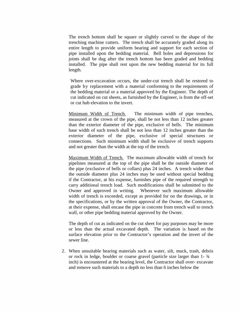
The trench bottom shall be square or slightly curved to the shape of the trenching machine cutters. The trench shall be accurately graded along its entire length to provide uniform bearing and support for each section of pipe installed upon the bedding material. Bell holes and depressions for joints shall be dug after the trench bottom has been graded and bedding installed. The pipe shall rest upon the new bedding material for its full length.
Where over-excavation occurs, the under-cut trench shall be restored to grade by replacement with a material conforming to the requirements of the bedding material or a material approved by the Engineer. The depth of cut indicated on cut sheets, as furnished by the Engineer, is from the off-set or cut hub elevation to the invert.
Minimum Width of Trench. The minimum width of pipe trenches, measured at the crown of the pipe, shall be not less than 12 inches greater than the exterior diameter of the pipe, exclusive of bells. The minimum base width of such trench shall be not less than 12 inches greater than the exterior diameter of the pipe, exclusive of special structures or connections. Such minimum width shall be exclusive of trench supports and not greater than the width at the top of the trench.
Maximum Width of Trench. The maximum allowable width of trench for pipelines measured at the top of the pipe shall be the outside diameter of the pipe (exclusive of bells or collars) plus 24 inches. A trench wider than the outside diameter plus 24 inches may be used without special bedding if the Contractor, at his expense, furnishes pipe of the required strength to carry additional trench load. Such modifications shall be submitted to the Owner and approved in writing. Whenever such maximum allowable width of trench is exceeded, except as provided for on the drawings, or in the specifications, or by the written approval of the Owner, the Contractor, at their expense, shall encase the pipe in concrete from trench wall to trench wall, or other pipe bedding material approved by the Owner.
The depth of cut as indicated on the cut sheet for pay purposes may be more or less than the actual excavated depth. The variation is based on the surface elevation prior to the Contractor’s operation and the invert of the sewer line.
2. When unsuitable bearing materials such as water, silt, muck, trash, debris
or rock in ledge, boulder or coarse gravel (particle size larger than 1- ¾ inch) is encountered at the bearing level, the Contractor shall over- excavate
and remove such materials to a depth no less than 6 inches below the
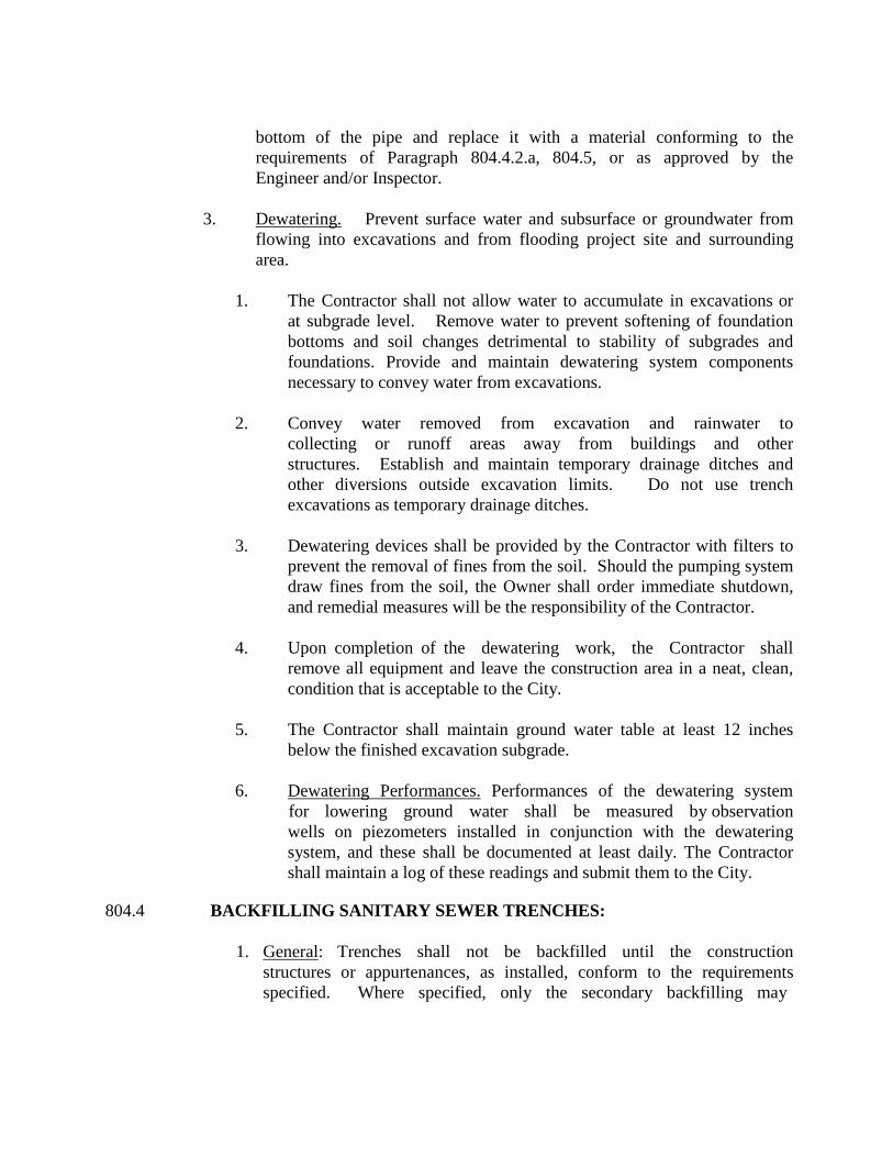
bottom of the pipe and replace it with a material conforming to the requirements of Paragraph 804.4.2.a, 804.5, or as approved by the Engineer and/or Inspector.
3. Dewatering. Prevent surface water and subsurface or groundwater from
flowing into excavations and from flooding project site and surrounding area.
1. The Contractor shall not allow water to accumulate in excavations or
at subgrade level. Remove water to prevent softening of foundation bottoms and soil changes detrimental to stability of subgrades and foundations. Provide and maintain dewatering system components necessary to convey water from excavations.
2. Convey water removed from excavation and rainwater to
collecting or runoff areas away from buildings and other structures. Establish and maintain temporary drainage ditches and other diversions outside excavation limits. Do not use trench excavations as temporary drainage ditches.
3. Dewatering devices shall be provided by the Contractor with filters to
prevent the removal of fines from the soil. Should the pumping system draw fines from the soil, the Owner shall order immediate shutdown, and remedial measures will be the responsibility of the Contractor.
4. Upon completion of the dewatering work, the Contractor shall
remove all equipment and leave the construction area in a neat, clean, condition that is acceptable to the City.
5. The Contractor shall maintain ground water table at least 12 inches
below the finished excavation subgrade.
6. Dewatering Performances. Performances of the dewatering system for lowering ground water shall be measured by observation wells on piezometers installed in conjunction with the dewatering system, and these shall be documented at least daily. The Contractor shall maintain a log of these readings and submit them to the City.
804.4 BACKFILLING SANITARY SEWER TRENCHES:
1. General: Trenches shall not be backfilled until the construction structures or appurtenances, as installed, conform to the requirements specified. Where specified, only the secondary backfilling may
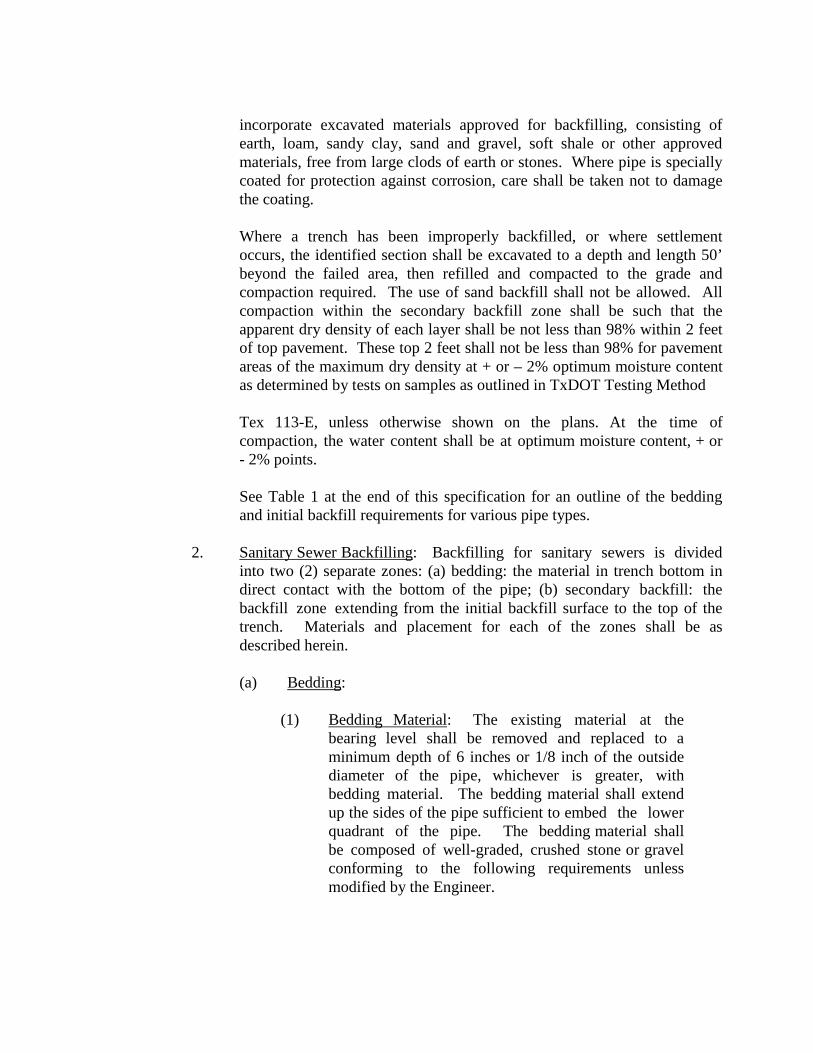
incorporate excavated materials approved for backfilling, consisting of earth, loam, sandy clay, sand and gravel, soft shale or other approved materials, free from large clods of earth or stones. Where pipe is specially coated for protection against corrosion, care shall be taken not to damage the coating.
Where a trench has been improperly backfilled, or where settlement occurs, the identified section shall be excavated to a depth and length 50’ beyond the failed area, then refilled and compacted to the grade and compaction required. The use of sand backfill shall not be allowed. All compaction within the secondary backfill zone shall be such that the apparent dry density of each layer shall be not less than 98% within 2 feet of top pavement. These top 2 feet shall not be less than 98% for pavement areas of the maximum dry density at + or – 2% optimum moisture content as determined by tests on samples as outlined in TxDOT Testing Method Tex 113-E, unless otherwise shown on the plans. At the time of compaction, the water content shall be at optimum moisture content, + or - 2% points.
See Table 1 at the end of this specification for an outline of the bedding and initial backfill requirements for various pipe types.
2. Sanitary Sewer Backfilling: Backfilling for sanitary sewers is divided into two (2) separate zones: (a) bedding: the material in trench bottom in direct contact with the bottom of the pipe; (b) secondary backfill: the backfill zone extending from the initial backfill surface to the top of the trench. Materials and placement for each of the zones shall be as described herein.
(a) Bedding:
(1) Bedding Material: The existing material at the bearing level shall be removed and replaced to a minimum depth of 6 inches or 1/8 inch of the outside diameter of the pipe, whichever is greater, with bedding material. The bedding material shall extend up the sides of the pipe sufficient to embed the lower quadrant of the pipe. The bedding material shall be composed of well-graded, crushed stone or gravel conforming to the following requirements unless modified by the Engineer.
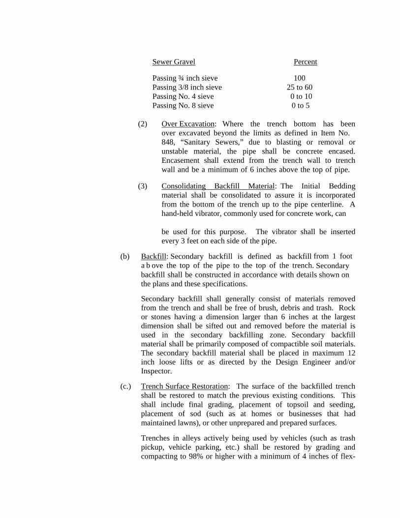
Sewer Gravel Percent
Passing ¾ inch sieve 100 Passing 3/8 inch sieve 25 to 60 Passing No. 4 sieve 0 to 10 Passing No. 8 sieve 0 to 5
(2) Over Excavation: Where the trench bottom has been
over excavated beyond the limits as defined in Item No. 848, “Sanitary Sewers,” due to blasting or removal or unstable material, the pipe shall be concrete encased. Encasement shall extend from the trench wall to trench wall and be a minimum of 6 inches above the top of pipe.
(3) Consolidating Backfill Material: The Initial Bedding material shall be consolidated to assure it is incorporated from the bottom of the trench up to the pipe centerline. A hand-held vibrator, commonly used for concrete work, can
be used for this purpose. The vibrator shall be inserted
every 3 feet on each side of the pipe.
(b) Backfill: Secondary backfill is defined as backfill from 1 foot a b ove the top of the pipe to the top of the trench. Secondary backfill shall be constructed in accordance with details shown on the plans and these specifications.
Secondary backfill shall generally consist of materials removed from the trench and shall be free of brush, debris and trash. Rock or stones having a dimension larger than 6 inches at the largest dimension shall be sifted out and removed before the material is used in the secondary backfilling zone. Secondary backfill material shall be primarily composed of compactible soil materials. The secondary backfill material shall be placed in maximum 12 inch loose lifts or as directed by the Design Engineer and/or Inspector.
(c.) Trench Surface Restoration: The surface of the backfilled trench
shall be restored to match the previous existing conditions. This shall include final grading, placement of topsoil and seeding, placement of sod (such as at homes or businesses that had maintained lawns), or other unprepared and prepared surfaces. Trenches in alleys actively being used by vehicles (such as trash pickup, vehicle parking, etc.) shall be restored by grading and compacting to 98% or higher with a minimum of 4 inches of flex-
base materials for the entire width of the alley. Alleys not actively used by vehicles shall be graded and compacted to 98% or higher, then spread grass seed for entire width of the alley.
Trenches in paved streets shall be covered with a temporary all- weather surface to allow for vehicular traffic until the final asphalt/concrete paving is complete. This surface shall be a minimum of 4 inches compacted and rolled asphaltic black base, either hot-mix or cold-mix applied. It is the Contractor’s responsibility to maintain this surface until the final street restoration is complete. Temporary street striping may also be required. This surface must be removed prior to final asphalting. All street work shall be done in accordance with the latest City requirements. Included in this requirement is replacement of any curbs or sidewalks damaged or removed during the construction.
804.5 BACKFILLING POTABLE WATER TRENCHES
Mains and service line trenches shall be excavated in accordance with Item No. 804.2 and Item No. 804.3 for placement of potable water appurtences. 1. Bedding/Initial Backfilling: The bedding & initial backfill materials for
concrete steel cylinder pipe (CSC), ductile iron pipe (DI), H.D.P.E. Pipe, Wrapped Steel Pipe, and Polyvinyl Chloride Pipe (PVC) in all nominal diameters shall be composed or well graded crushed stone or gravel in accordance with Item 848.2.7; M o d i f i e d G r a d e 5 , unless modified by the Engineer of Record and approved by the City Engineer.
The quantity and thickness of materials lifts and compaction of initial backfill materials shall be in accordance with the provisions shown on Detai l DD-804-02.
Where services ¾” – 2” copper is installed, initial backfill shall be sand conforming to the following requirements: Natural sand or sand produced from crushed gravel or crushed rock maximum ¼-inch; 95 percent shall pass No. 4 sieve, free from clay and organic material, with a maximum 8 percent passing the No. 200 sieve. Larger services utilizing DI pipe or PVC (C-900) pipe shall be backfilled the same as mains.
2. Trench Surface Restoration: Trench surface restoration shall be accomplished as defined in Item No. 804.4.
804.6 DISPOSAL OF EXCAVATED MATERIALS: Any excess excavated
material, not utilized after all fill requirements have been met, shall become the
responsibility of the Contractor. The Contractor shall dispose of it by hauling and wasting outside the limits of the right-of-way of this project and of public thoroughfares and water courses, in conformity with pertinent City, County, State and Federal codes and ordinances and in a manner meeting the approval of the Engineer of Record.
804.7 QUALITY CONTROL:
1. The Contractor shall procure, store, and place materials from either onsite or offsite sources which comply with the specified requirements.
2. Quality Assurance Testing: The City or Contractor shall have such tests and inspections as he may desire performed by a nationally-accredited, independent testing laboratory for g uidance and control of the work. Payment for such tests shall be the responsibility of the Owner, including the material proctor tests and density tests. The Contractor shall request testing work performed by the Owner by notifying the Owner of the areas available by Station Numbers or Dimensions and Lift Numbers. The Contractor shall provide access to the test area, associated trench excavation safety protection, and backfilling of the test areas. The frequency and location of testing shall be determined solely by the Owner. The Owner may test any lift of fill at any time, location, or elevation.
3. Quality Control Testing. The Contractor shall be responsible for compaction in accordance with the appropriate Specification. Compaction
tests will be done at one location point randomly selected or as indicated by the City of Cibolo, per each 12 inch loose lift per 400 linear feet.
Note: Tests requirements above are indicated as a minimum requirement, but maybe subjected to follow more stringent requirements as established by other appropriate agencies.
Note: Any failed test shall require the Contractor to remove and replace that layer of backfill to 50 feet from either side from the failed test location. The Contractor will also be required to provide two additional tests at the replaced location where the initial test failed and at one location point, randomly selected or as indicated by the City of Cibolo.
Note: Sanitary Sewer Laterals will be subject to compaction tests at the discretion of the C i t y o f C i b o l o within 400 linear foot segments. Any failed test shall require the Contractor to remove and replace failed backfill. The Contractor will also be required at no additional cost to City
of Cibolo to provide one test at the replaced location where the initial tests failed.
The Contractor is responsible for all costs associated with supplying material for the proctor and density tests. These tests shall be performed by a nationally-accredited, independent testing laboratory. The Owner shall provide access to the results of the material proctor tests to the Contractor prior to performing any backfill operations.
The Contractor shall provide access to the test area, associated trench excavation safety protection, and backfilling of the test areas at the Contractor’s expense.
The Owner will determine in-place density and moisture content by any one or combination of the following methods: ASTM D2922 (density of soil and soil aggregate in-place by nuclear methods – shallow depth), D1556 (density and unit weight of soil in-place by sand cone method), D2216 (lab density of water content of soil and rock), D3017 (water content of soil and rock – shallow depth in-place by nuclear methods).
ITEM NO. 808
REINFORCED CONCRETE VAULTS 808.1 DESCRIPTION: Reinforced concrete vaults shall be cast-in-place and shall
include reinforcing steel, forms, finishing, curing, and all other appurtenant work required to provide a complete and functional structure.
All cast-in-place concrete shall be accurately formed and properly placed and finished as shown on the plans, the Standard Drawings, and as specified herein.
The Contractor shall inform the Engineer at least 24 hours in advance, of time and location at which he/she intends to place concrete in order for inspection of forms, reinforcing steel placement, and other preparatory work.
Precast vaults conforming to the Standard Drawings and Specifications shall be acceptable as a substitute to the cast-in-place vaults or as approved by the Engineer.
808.2 MATERIALS:
Concrete: Concrete used shall be transit mix and shall have a 28 day compressive strength of 3,000 psi with a maximum slump of 6 inches and a minimum slump of 3 inches. The use of admixtures shall not be permitted unless approved by the Engineer. Cement shall be Type I or Type III and shall conform to the general requirements contained in the Materials Specifications Item 100-10 and the ASTM Specifications C150-56.
808.3 CONSTRUCTION:
1. Forms: Forms shall be designed to produce hardened concrete having the
shape, lines, and dimensions shown on the drawings.
Surfaces which will be exposed to view when construction is completed shall be prefabricated plywood panel forms, job-built plywood forms, or forms that are lined with plywood or fiberboard. The forms shall produce finished surfaces that are free from off-sets, ridges, waves, and concave or convex areas.
Plywood or lined forms will not be required for surfaces which are normally submerged or not ordinarily exposed to view. Other types of
forms, such as steel or unlined wooden forms, may be used for surfaces which are not restricted to plywood or lined forms and may be used as backing for form linings.
Before concrete is placed, a film of light form oil shall be applied to the forms.
Forms shall be substantial and sufficiently tight to prevent leakage of mortar. Forms shall be thoroughly cleaned, braced, or tied to maintain the desired position, shape, and alignment during and after concrete placement.
Form ties shall be corrosion resistant and shall have sufficient strength and rigidity to support and maintain the form in proper position and alignment.
2. Form Removal: Forms shall be removed after 24 hours provided exposed
surfaces can be immediately and effectively sealed to prevent loss of moisture; otherwise, the forms shall remain in place for 48 hours. Precautions shall be taken in form removal to avoid surface gouging, corner or edge breaking, and other damage to the concrete.
3. Reinforcing Steel: Reinforcing steel shall be accurately formed and shall
be free from loose rust, scale, and contaminants which reduce bond. Unless otherwise shown on the drawings or specified herein, bar reinforcement shall be deformed and conform to the general requirements contained in the Material Specifications.
4. Reinforcing Steel Placement: Reinforcing steel shall be accurately
positioned on supports, spaces, hangers, or other reinforcements and shall be secured in place with wire ties or suitable clips. All bars shall be shop fabricated and bent cold.
5. Concrete Placement: Concrete shall be placed as nearly as practicable in
its final position to avoid segregation due to rehandling. When the concrete pour has commenced, it shall be carried on as a continuous operation until the placing of the panel or section is completed as a whole. All concrete shall be thoroughly compacted by suitable means during pouring operations and shall be thoroughly worked around reinforcement bars and into the corners of the forms. Mechanical vibration or other acceptable means shall be used to completely embed the reinforcement and eliminate honeycomb. Finished surfaces shall be brought to proper
grade, struck off, & completed in a workmanlike manner. Honeycombing, rough spots or protruding stones shall be left exposed.
6. Curing: Concrete shall be protected from loss of moisture for at least 7 days after placement. Curing of concrete shall be by methods which will keep the concrete surfaces adequately wet during the curing period.
a. Water Curing: Water saturation of concrete surfaces shall begin as
quickly as possible after the initial set of the concrete. The rate of water application shall be regulated to provide complete surface coverage with a minimum of runoff.
b. Membrane Curing: Chlorinated, rubber-type, membrane curing
compound may be used in lieu of water curing on concrete which will not be covered later with mortar or additional concrete.
Membrane curing compound shall be spray applied at coverage of not more than 300 square feet per gallon. If forms are removed before the end of the specified curing period, curing compound shall be immediately applied to the formed surfaces before they dry out. Curing compound shall be suitably protected against abrasion during the curing period.
7. Finishing Surfaces: Fins and other surface projections shall be removed from all formed surfaces. All exposed exterior surfaces shall have a rubbed finish. The floor surface shall be brush finished, unless otherwise specified.
8. Repairing Defective Concrete: Defects in formed concrete surfaces shall
be repaired to the satisfaction of the Engineer within 24 hours, and defective concrete shall be replaced within 48 hours after the forms have been removed. All concrete which is honeycombed or otherwise defective shall be cut out and removed to sound concrete with edges square cut to avoid feathering. Concrete repair work shall be performed in a manner that will not interfere with thorough curing of surrounding concrete. Repair work shall be adequately cured.
9. Painting: All exposed metallic surfaces such as the cover plate, hinges,
handles, and other exposed hardware shall be primed and painted with one coat of primer and one coat of aluminum paint of approved and compatible quality.
10. Backfill: The Contractor shall cover the openings at each end of the vault
with ¼ inch plywood placed outside the vault. Select backfill consisting of job excavated materials, finely divided and free from debris, organic material and stones larger than four 4 inches in greatest dimension, shall be placed in uniform layers not exceeding 8 inches in un-compacted thickness and shall be carefully compacted around the sides of the vault until level with the surrounding ground.
ITEM NO. 809 REINFORCED CONCRETE VAULTS FOR METERED FIRELINE
SERVICES 809.1 DESCRIPTION: Reinforced concrete vaults shall be precasted with
reinforcing steel and include all other appurtenant work required to provide a complete and functional structure.
All precast concrete vaults shall be accurately formed and finished as shown on the plans, the Standard Drawings, and as specified herein.
Precast vaults conforming to the Standard Drawings and Specifications shall be acceptable as a substitute to the cast-in-place vaults or as approved by the Engineer. Contractor will give 24 hour notification to the Inspector assigned to the project before setting a metered fire line vault.
809.2 MATERIALS:
Concrete: Concrete used shall be transit mix and shall have a 28 day compressive strength of 3,000 psi with a maximum slump of 6 inches and a minimum slump of 3 inches. The use of admixtures shall not be permitted unless approved by the Engineer. Cement shall be Type I or Type III and shall conform to the general requirements contained in the Materials Specifications Item 100-10 and the ASTM Specifications C150-56.
809.3 CONSTRUCTION:
1. Forms: Forms shall be designed to produce hardened concrete having the shape, lines, and dimensions shown on the drawings.
Surfaces which will be exposed to view when construction is completed shall be prefabricated plywood panel forms, job-built plywood forms, or forms that are lined with plywood or fiberboard. The forms shall produce finished surfaces that are free from off-sets, ridges, waves, and concave or convex areas.
Plywood or lined forms will not be required for surfaces which are normally submerged or not ordinarily exposed to view. Other types of forms, such as steel or unlined wooden forms, may be used for surfaces which are not restricted to plywood or lined forms and may be used as backing for form linings.
Before concrete is placed, a film of light form oil shall be applied to the
forms. Forms shall be substantial and sufficiently tight to prevent leakage of mortar. Forms shall be thoroughly cleaned, braced, or tied to maintain the desired position, shape, and alignment during and after concrete placement.
Form ties shall be corrosion resistant and shall have sufficient strength and rigidity to support and maintain the form in proper position and alignment.
2. Form Removal: Forms shall be removed after 24 hours provided exposed surfaces can be immediately and effectively sealed to prevent loss of moisture; otherwise, the forms shall remain in place for 48 hours. Precautions shall be taken in form removal to avoid surface gouging, corner or edge breaking, and other damage to the concrete.
3. Reinforcing Steel: Reinforcing steel shall be accurately formed and shall be free from loose rust, scale, and contaminants which reduce bond. Unless otherwise shown on the drawings or specified herein, bar reinforcement shall be deformed and conform to the general requirements contained in the Material Specifications.
4. Reinforcing Steel Placement: Reinforcing steel shall be
accurately positioned on supports, spaces, hangers, or other reinforcements and shall be secured in place with wire ties or suitable clips. All bars shall be shop fabricated and bent cold.
5. Concrete Placement: Concrete shall be placed as nearly as practicable
in its final position to avoid segregation due to rehandling. When the concrete pour has commenced, it shall be carried on as a continuous operation until the placing of the panel or section is completed as a whole. All concrete shall be thoroughly compacted by suitable means during pouring operations and shall be thoroughly worked around reinforcement bars and into the corners of the forms. Mechanical vibration or other acceptable means shall be used to completely embed the reinforcement and eliminate honeycomb. Finished surfaces shall be brought to proper grade, struck off, and completed in a workmanlike manner. No honeycombing, rough spots or protruding stones shall be left exposed.
6. Curing: Concrete shall be protected from loss of moisture for at least
7 days after placement. Curing of concrete shall use methods which keep the concrete surfaces adequately wet during the specified curing

period.
a. Water Curing: Water saturation of concrete surfaces shall begin as quickly as possible after the initial set of the concrete. The rate of water application shall be regulated to provide complete surface coverage with a minimum of runoff.
b. Membrane Curing: Chlorinated, rubber-type, membrane curing
compound may be used in lieu of water curing on concrete which will not be covered later with mortar or additional concrete.
Membrane curing compound shall be spray applied at coverage of not more than 300 square feet per gallon. If forms are removed before the end of the specified curing period, curing compound shall be immediately applied to the formed surfaces before they dry out.
Curing compound shall be suitably protected against abrasion during the curing period.
7. Finishing Surfaces: Fins and other surface projections shall be
removed from all formed surfaces. All exposed exterior surfaces shall have a rubbed finish. The floor surface shall be brush finished, unless otherwise specified.
8. Repairing Defective Concrete: Defects in formed concrete surfaces
shall be repaired to the satisfaction of the Engineer within 24 hours, and defective concrete shall be replaced within 48 hours after the forms have been removed. All concrete which is honeycombed or otherwise defective shall be cut out and removed to sound concrete with edges square cut to avoid feathering.
Concrete repair work shall be performed in a manner that will not interfere with thorough curing of surrounding concrete. Repair work shall be adequately cured.
9. Painting: All exposed metallic surfaces such as the cover plates,
hinges, handles, and other exposed hardware shall be primed and painted with one coat of primer and one coat of aluminum paint of approved and compatible quality.
10. Backfill: The Contractor shall cover the openings at each end of the
vault with grout placed around the pipe penetration inside and outside of

the vault. Select backfill consisting of job excavated materials, finely divided and free from debris, organic material and stones larger than 2 inches in greatest dimension, shall be placed in uniform layers not exceeding 8 inches in uncompacted thickness and shall be carefully compacted around the sides of the vault until level with the surrounding ground.
ITEM NO. 812 WATER MAIN INSTALLATION
812.1 DESCRIPTION: This item shall consist of water main installation in
accordance with these specifications and as directed by the Engineer.
812.2 MATERIALS: The materials for water main installation shall conform to the specifications contained within the latest revision of SAWS Material Specifications "Ductile Iron Pipe", Item No. 05-11, "Steel Water Pipe", Item No. 05-30, "PVC C-900 Water Pipe", Item No. 05-12, “PVC C-905 Water Pipe”, Item No. 819 and "Reinforced Concrete Water Pipe Steel Cylinder Type", Item No. 05-20. The pressure rating for pipe materials shall be in accordance with Table HP, "High Pressure Levels," in Appendix A. Minimum pressure rating for all pipes in high pressure zones shall be 200 psi.
812.3 CONSTRUCTION:
1. Start of Work: The Contractor shall start his work at a tie-in or point designated by the Engineer. Pipe shall be laid with bell ends facing in the direction of pipe laying, unless otherwise authorized or directed by the Engineer. All valves and fire hydrants must be installed as soon as pipe laying reaches their established location. Pipe shall be installed to the required lines and grades with fittings, valves, and hydrants placed at the required locations. Spigots shall be centered in bells or collars, all valves and hydrant stems shall be set plumb, and fire hydrant nozzles shall face as per City of Cibolo standard details or as directed by the Engineer. No valve or other control on the existing system shall be operated for any purpose by the Contractor unless a representative of the City of Cibolo is present.
2. Crossing Other Underground Lines: New water mains crossing any
other utilities shall have a minimum of 30 inches of cover over the top of the pipe unless otherwise waived or modified by the Engineer. Excavation around other utilities shall be done by hand for at least 12 inches all around. Any damage to the protective wrap on gas lines or electrodes shall be reported immediately to the p r o p e r g o v e r n i n g e n t i t y . A ny damage to other utilities shall be reported to their proper governing entity.
3. Pipe Grade: Water mains 16" or smaller shall have a minimum of
4 8 inches of cover from the proposed final finish ground/street/elevation and 60 inches of cover when the main is in a
parkway or under the pavement where there are no existing/proposed curb or existing drainage facilities.
A water main 20" and above shall have a minimum of 60 inches of cover over the top of the pipe from the proposed final finish ground/street/elevation unless otherwise waived or modified by the Engineer. Pipe grades shall be as required by the plans or as directed by the Engineer. Grades shall be met as specified by “Excavation, Trenching and Backfilling", Item No. 804. Precaution shall be taken to insure that the pipe barrel has uniform contact with the cushion material for its full length except at couplings. The couplings shall not be in contact with the original trench bottom prior to backfilling. Cushion material shall be placed under the coupling and compacted by hand prior to backfilling so as to provide an even bearing surface under the coupling and pipe. Changes in grade shall be made only at joints.
4. Cushion and Cushion Materials: Prior to placing pipe in a trench,
the trench shall have been excavated to the proper depth as required in "Excavation, Trenching, and Backfilling", Item No. 804, of these specifications. Approved imported materials or Engineer approved materials selected from suitable fines derived from the excavation shall be smoothly worked across the entire width of the trench bottom to provide a supporting cushion.
5. Structures to Support Pipe: Where the bottom of a trench at
subgrade consists of material that is notably unstable by the Engineer and cannot be removed and replaced with approved material which may be properly compacted in place to support the pipe. The Contractor shall also construct a foundation for the pipe consisting of piling, concrete beams, or other supports in accordance with plans prepared by the Engineer.
6. Lowering Materials into Trench: Proper implements, tools, and facilities satisfactory to the Engineer shall be provided and used by the
Contractor for the safe and convenient completion of work. All pipe,
fittings, valves, and hydrants shall be carefully lowered into the trench piece by piece, by means of a derrick, ropes, or other suitable tools or equipment in such a manner as to prevent damage to water main materials and protective coatings and linings. Under no circumstances shall water main materials, pipes, fittings, and the like, be dropped or dumped into the trench. Extreme care shall be taken to avoid damaging polywrap films. No chains or slings shall be
allowed unless the entire sling is wrapped with a protective nylon web sock.
7. Pipe Laying: Every precaution shall be taken to prevent foreign
material from entering the pipe during installation. Under adverse trenching conditions, work stoppage for an extended period of time and/or otherwise required by the Engineer, a manufactured cap/plug is to be used to prevent any foreign type material entering. The cap/plug shall be left in place until it is connection to an adjacent pipe. The interior of each pipe shall be inspected for defects, and the pipe shall be rejected if any defects are found.
After placing a length of pipe in the trench, the jointed end shall be centered on the pipe already in place, forced into place, brought to correct line and grade, and completed in accordance with the requirements of these Specifications. The pipe shall be secured in place with approved backfill material tamped around it. Pipe and fittings which do not allow a sufficient and uniform space for joints shall be rejected by the Engineer and shall be replaced with pipe and fittings of proper dimensions. Precautions shall be taken to prevent dirt or other foreign matter from entering the joint space.
At times when pipe laying is halted, the open end of pipe in the trench shall be closed by a watertight plug or other means approved by the Engineer. Pipe in the trench which cannot temporarily be jointed shall be capped or plugged at each end to make it watertight. This provision shall apply during all periods when pipe laying is not in progress. Should water enter the trench, the seal shall remain in place until the trench is pumped completely dry. The Contractor shall provide all plugs and caps of the various sizes required.
8. Deviations in Line or Grade: Wherever obstructions not shown on
the plans are encountered during the progress of the work and interfere to an extent that an alteration in the plan is required, the Engineer shall have the authority to change the plans and direct a deviation from the line and grade or to arrange with the owners of the structures for
the removal, relocation, or reconstruction of the obstructions. Any
deviation from the line shall be accomplished by the use of appropriate bends unless such requirement is specifically waived by the Engineer.
Whenever it is necessary to deflect pipe from a straight line, the deflection shall be as directed by the Engineer and as described
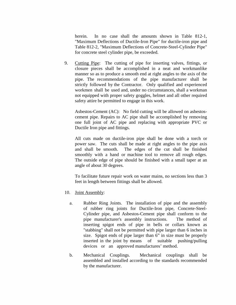
herein. In no case shall the amounts shown in Table 812-1, "Maximum Deflections of Ductile-Iron Pipe" for ductile-iron pipe and Table 812-2, "Maximum Deflections of Concrete-Steel-Cylinder Pipe" for concrete steel cylinder pipe, be exceeded.
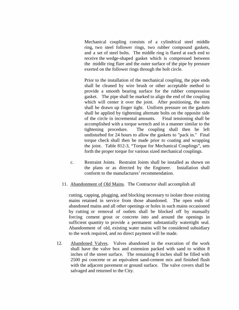
9. Cutting Pipe: The cutting of pipe for inserting valves, fittings, or
closure pieces shall be accomplished in a neat and workmanlike manner so as to produce a smooth end at right angles to the axis of the pipe. The recommendations of the pipe manufacturer shall be strictly followed by the Contractor. Only qualified and experienced workmen shall be used and, under no circumstances, shall a workman not equipped with proper safety goggles, helmet and all other required safety attire be permitted to engage in this work.
Asbestos-Cement (AC): No field cutting will be allowed on asbestos- cement pipe. Repairs to AC pipe shall be accomplished by removing one full joint of AC pipe and replacing with appropriate PVC or Ductile Iron pipe and fittings.
All cuts made on ductile-iron pipe shall be done with a torch or power saw. The cuts shall be made at right angles to the pipe axis and shall be smooth. The edges of the cut shall be finished smoothly with a hand or machine tool to remove all rough edges. The outside edge of pipe should be finished with a small taper at an angle of about 30 degrees.
To facilitate future repair work on water mains, no sections less than 3 feet in length between fittings shall be allowed.
10. Joint Assembly:
a. Rubber Ring Joints. The installation of pipe and the assembly
of rubber ring joints for Ductile-Iron pipe, Concrete-Steel-Cylinder pipe, and Asbestos-Cement pipe shall conform to the pipe manufacturer's assembly instructions. The method of inserting spigot ends of pipe in bells or collars known as "stabbing" shall not be permitted with pipe larger than 6 inches in size. Spigot ends of pipe larger than 6” in size must be properly inserted in the joint by means of suitable pushing/pulling devices or an approved manufactures’ method.
b. Mechanical Couplings. Mechanical couplings shall be
assembled and installed according to the standards recommended by the manufacturer.
Mechanical coupling consists of a cylindrical steel middle ring, two steel follower rings, two rubber compound gaskets, and a set of steel bolts. The middle ring is flared at each end to receive the wedge-shaped gasket which is compressed between the middle ring flare and the outer surface of the pipe by pressure exerted on the follower rings through the bolt circle.
Prior to the installation of the mechanical coupling, the pipe ends shall be cleaned by wire brush or other acceptable method to provide a smooth bearing surface for the rubber compression gasket. The pipe shall be marked to align the end of the coupling which will center it over the joint. After positioning, the nuts shall be drawn up finger tight. Uniform pressure on the gaskets shall be applied by tightening alternate bolts on the opposite side of the circle in incremental amounts. Final tensioning shall be accomplished with a torque wrench and in a manner similar to the tightening procedure. The coupling shall then be left undisturbed for 24 hours to allow the gaskets to "pack in." Final torque check shall then be made prior to coating and wrapping the joint. Table 812-3, “Torque for Mechanical Couplings”, sets forth the proper torque for various sized mechanical couplings.
c. Restraint Joints. Restraint Joints shall be installed as shown on
the plans or as directed by the Engineer. Installation shall conform to the manufactures’ recommendation.
11. Abandonment of Old Mains. The Contractor shall accomplish all cutting, capping, plugging, and blocking necessary to isolate those existing
mains retained in service from those abandoned. The open ends of abandoned mains and all other openings or holes in such mains occasioned by cutting or removal of outlets shall be blocked off by manually forcing cement grout or concrete into and around the openings in sufficient quantity to provide a permanent substantially watertight seal. Abandonment of old, existing water mains will be considered subsidiary to the work required, and no direct payment will be made.
12. Abandoned Valves. Valves abandoned in the execution of the work
shall have the valve box and extension packed with sand to within 8 inches of the street surface. The remaining 8 inches shall be filled with 2500 psi concrete or an equivalent sand-cement mix and finished flush with the adjacent pavement or ground surface. The valve covers shall be salvaged and returned to the City.
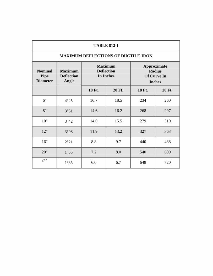
TABLE 812-1
MAXIMUM DEFLECTIONS OF DUCTILE-IRON
Nominal Pipe
Diameter
Maximum Deflection
Angle
Maximum Deflection In Inches
Approximate Radius
Of Curve In Inches
18 Ft.
20 Ft.
18 Ft.
20 Ft.
6"
4°25'
16.7
18.5
234
260
8"
3°51'
14.6
16.2
268
297
10"
3°42'
14.0
15.5
279
310
12"
3°08'
11.9
13.2
327
363
16"
2°21'
8.8
9.7
440
488
20"
1°55'
7.2
8.0
540
600
24”
1°35'
6.0
6.7
648
720
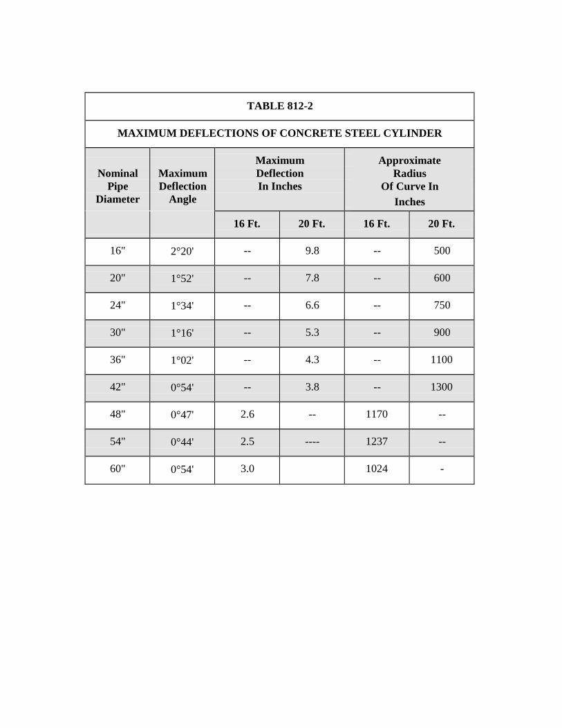
TABLE 812-2
MAXIMUM DEFLECTIONS OF CONCRETE STEEL CYLINDER
Nominal Pipe
Diameter
Maximum Deflection
Angle
Maximum Deflection In Inches
Approximate Radius
Of Curve In Inches
16 Ft.
20 Ft.
16 Ft.
20 Ft.
16"
2°20'
--
9.8
--
500
20"
1°52'
--
7.8
--
600
24"
1°34'
--
6.6
--
750
30"
1°16'
--
5.3
--
900
36"
1°02'
--
4.3
--
1100
42"
0°54'
--
3.8
--
1300
48"
0°47'
2.6
--
1170
--
54"
0°44'
2.5
----
1237
--
60"
0°54'
3.0
1024
-
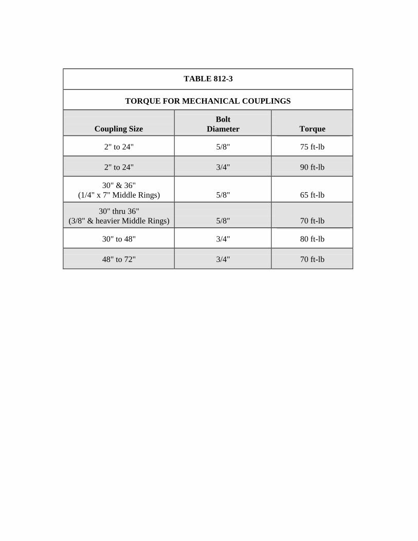
TABLE 812-3
TORQUE FOR MECHANICAL COUPLINGS
Coupling Size
Bolt Diameter
Torque
2" to 24"
5/8"
75 ft-lb
2" to 24"
3/4"
90 ft-lb
30" & 36" (1/4" x 7" Middle Rings)
5/8"
65 ft-lb
30" thru 36" (3/8" & heavier Middle Rings)
5/8"
70 ft-lb
30" to 48"
3/4"
80 ft-lb
48" to 72"
3/4"
70 ft-lb
ITEM NO. 813
WATER SERVICE FOR FIRELINES
813.1 DESCRIPTION: This item shall consist of water service for fire
line installations in accordance with these specifications and as directed by the Engineer.
813.2 MATERIALS: The materials for water service for fire lines shall conform to the specifications contained within the latest revision of SAWS Material Specifications "Ductile Iron Pipe", Item No. 05-11, "PVC C-900 Water Pipe", Item 05-12, “PVC C-905 Water Pipe”, Item No. 819. The pressure rating for pipe materials shall be in accordance with Table HP, "High Pressure Levels," in Appendix A. Minimum pressure rating for all pipes in high pressure zones shall be DR 18 standards.
813.3 CONSTRUCTION:
1. Start of Work: Three working days o f notice will be given to the
assigned Inspector prior to start of a project after permit has been issued. The Contractor shall start his work at a tie-in or point designated by the Engineer. Pipe shall be laid with bell ends facing in the direction of laying, unless otherwise authorized or directed by the Engineer. All valves and fire hydrants must be installed as soon as pipe laying reaches their established location. Pipe shall be installed to the required lines and grades with fittings, valves, and hydrants placed at the required locations. Spigots shall be centered in bells or collars, all valves and hydrant stems shall be set plumb, and fire hydrant nozzles shall face as shown on the plans or as directed by the Engineer. No valve or other control on the existing system shall be operated for any purpose by the Contractor unless a representative of the City of Cibolo is present.
2. Crossing Other Underground Lines: New fire line services crossing
any other utilities shall have a minimum of 48 inches of cover over the top of the pipe unless otherwise waived or modified by the Engineer. Excavation around other utilities shall be done by hand for at least 12 inches all around. Any damage to other utilities shall be reported to their proper governing entity.
3. Pipe Grade: Fire line services shall have a minimum of 48 inches of
cover for mains 16” and below, and 60 inches for mains 20” and above,
over the top of the pipe unless otherwise waived or modified by the Engineer. Pipe grades shall be as required by the plans or as directed by the Engineer. Grades shall be met as specified by "Excavation, Trenching and Backfilling", Item No. 804. Precautions shall be taken to insure that the pipe barrel has uniform contact with the Modified Grade 5 for its full length except at couplings. Couplings shall not be in contact with the original trench bottom prior to backfilling. Modified Grade 5 material shall be placed under the coupling and compacted by hand prior to backfilling so as to provide an even bearing surface under the coupling and pipe. Changes in grade shall be made only at joints.
4. Modified Grade 5 Materials: Prior to placing pipe in a trench, the trench
shall have been excavated to the proper depth as required in "Excavation, Trenching, and Backfilling", Item No. 804 of these specifications. Approved imported materials or Engineer approved materials selected from suitable fines derived from the excavation shall be smoothly worked across the entire width of the trench bottom to provide a supporting cushion.
5. Structures to Support Pipe: Whereas the bottom of a trench at subgrade consist of material that is notably unstable by the Engineer and cannot be removed and replaced with approved material may be properly compacted in place to support the pipe. The Contractor shall also construct a foundation for the pipe consisting of piling, concrete beams, or other supports in accordance with plans prepared by the Engineer.
6. Lowering Materials into Trench: Proper implements, tools, and facilities
satisfactory to the Engineer shall be provided and used by the Contractor for the safe and convenient completion of work. All pipe, fittings, valves, and hydrants shall be carefully lowered into the trench piece by piece, by means of a derrick, ropes, or other suitable tools or equipment in such a manner as to prevent damage to water service materials and protective coatings and linings. Under no circumstances shall water service materials, pipes, fittings, etc., be dropped or dumped into the trench. Extreme care shall be taken to avoid damaging polywrap films. No chains or slings shall be allowed unless the entire sling is wrapped with a protective nylon web sock.
7. Laying of Pipe: Every precaution shall be taken to prevent foreign
material from entering the pipe during its installation. Under adverse trench conditions or otherwise required by the Engineer, a heavy, tightly
woven canvas bag of suitably sized shall be placed over each of the pipe. The Canvas bag shall be left in place until a connection is made to the adjacent pipe. The interior of each pipe shall be inspected for defects, and the pipe shall be rejected if any defects are found.
After placing a length of pipe in the trench, the jointed end shall be centered on the pipe already in place, forced into place, brought to correct line and grade, and completed in accordance with the requirements of these Specifications. The pipe shall be secured in place with approved backfill material tamped around it. Pipe and fittings which do not allow a sufficient and uniform space for joints shall be rejected and shall be replaced with pipe and fittings of proper dimensions. Precautions shall be taken to prevent dirt or other foreign matter from entering the joint space.
At times when pipe laying is halted, the open end of pipe in the trench shall be closed by a watertight plug or other means approved by the Engineer. Pipe in the trench which cannot temporarily be joined shall be capped or plugged at each end to make it watertight. This provision shall apply during all periods when pipe laying is not in progress. Should water enter the trench, the seal shall remain in place until the trench is pumped completely dry. The Contractor shall provide all plugs and caps of the various sizes required.
8. Deviations in Line or Grade: Wherever obstructions not shown on the
plans are encountered during the progress of the work and interfere to an extent that an alteration in the plan is required, the Construction Inspector shall have the authority to change the plans and direct a deviation from the line and grade or to arrange with the owners of the structures for the removal, relocation, or reconstruction of the obstructions. Any deviation from the line shall be accomplished by the use of appropriate bends unless such requirement is specifically waived by Construction Inspector.
Whenever it is necessary to deflect pipe from a straight line, the deflection shall be as directed by the Construction Inspector and as described herein. In no case shall the amounts exceed those shown in Table 813-1, "Maximum Deflections of Ductile-Iron Pipe" for ductile-iron pipe or the manufacturer’s recommendations for PVC pipe.
9. Cutting Pipe: The cutting of pipe for inserting valves, fittings, or closure
pieces shall be accomplished in a neat and workmanlike manner so as to produce a smooth end at right angles to the axis of the pipe. The recommendations of the pipe manufacturer shall be strictly followed by the Contractor. Only qualified and experienced workmen shall be used and, under no circumstances, shall a workman not equipped with proper
safety goggles, helmet and all other required safety attire be permitted to engage in this work.
Asbestos-Cement (AC): No field cutting will be allowed on asbestos- cement pipe. Installation of fire line services to AC pipe mains shall be accomplished by removing one full joint of AC pipe and replacing with appropriate PVC or Ductile Iron pipe and fittings.
All cuts made on ductile-iron pipe shall be done with a power saw. The cuts shall be made at right angles to the pipe axis and shall be smooth. The edges of the cut shall be finished smoothly with a hand or machine tool to remove all rough edges. The outside edge of pipe should be finished with a small taper at an angle of about 30 degrees. Solid sleeves or cast couplings shall be allowed on precast/prefab vaults only. All other fire line services shall be installed with full joints of pipe.
10. Joint Assembly:
a. Rubber Ring Joints: The installation of pipe and the assembly of
rubber ring joints for Ductile-Iron pipe shall conform to the pipe manufacturer's assembly instructions. The method of inserting spigot ends of pipe in bells or collars known as "stabbing" shall not be permitted. Spigot ends of pipe must be properly inserted in the joint by means of suitable pushing/pulling devices or a manufacture approved method.
b. Mechanical Couplings: Mechanical couplings shall be assembled and
installed according to the standards recommended by the manufacturer.
Mechanical coupling consists of a cylindrical steel middle ring, two steel follower rings, two rubber compound gaskets, and a set of steel bolts. The middle ring is flared at each end to receive the wedge-shaped gasket which is compressed between the middle ring flare and the outer surface of the pipe by pressure exerted on the follower rings through the bolt circle.
Prior to the installation of the mechanical coupling, the pipe ends shall be cleaned by wire brush or other acceptable method to provide a smooth bearing surface for the rubber compression gasket. The pipe shall be marked to align the end of the coupling which will center it over the joint. After positioning, the nuts shall be drawn up finger tight. Uniform pressure on the gaskets shall be applied by tightening alternate bolts on the opposite side of the circle in incremental amounts. Soap and final tensioning shall be accomplished with a torque wrench
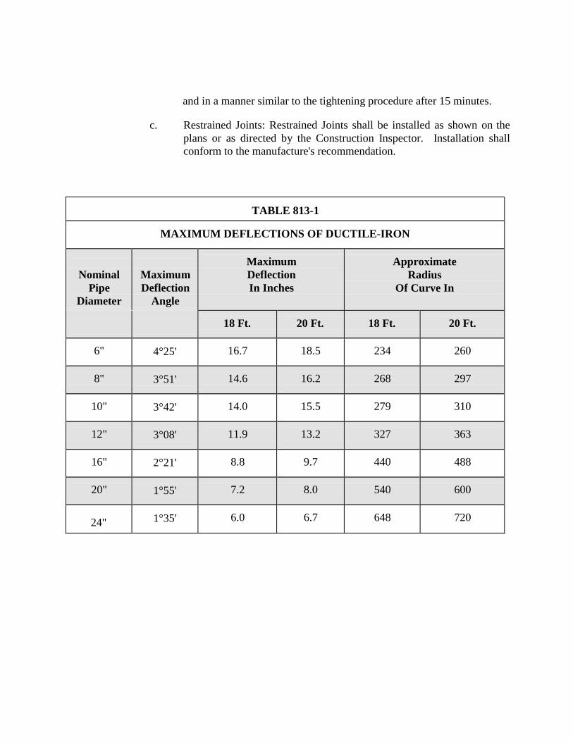
and in a manner similar to the tightening procedure after 15 minutes.
c. Restrained Joints: Restrained Joints shall be installed as shown on the plans or as directed by the Construction Inspector. Installation shall conform to the manufacture's recommendation.
TABLE 813-1
MAXIMUM DEFLECTIONS OF DUCTILE-IRON
Nominal Pipe
Diameter
Maximum Deflection
Angle
Maximum Deflection In Inches
Approximate Radius
Of Curve In
18 Ft.
20 Ft.
18 Ft.
20 Ft.
6"
4°25'
16.7
18.5
234
260
8"
3°51'
14.6
16.2
268
297
10"
3°42'
14.0
15.5
279
310
12"
3°08'
11.9
13.2
327
363
16"
2°21'
8.8
9.7
440
488
20"
1°55'
7.2
8.0
540
600
24"
1°35'
6.0
6.7
648
720
ITEM NO.
814 DUCTILE IRON
PIPE 814.1 DESCRIPTION: This item shall consist of Ductile Iron Pipe installation
in accordance with these specifications and as directed by the Engineer. 814.2 MATERIALS: The materials for Ductile-Iron pipe shall conform to
the specifications contained within the latest revision of SAWS Material Specification "Ductile-Iron Pipe", Item No. 05-11, "Gray-Iron and Ductile-Iron Fittings", Item No. 10-10, and "Ductile-Iron Couplings", Item 100-34.
814.3 CONSTRUCTION METHOD:
1. Excavations at Bells and Collars: Ductile Iron pipe shall be
installed as specified within "Water Main Installation", Item No. 812, of these specifications. Bell holes of sufficient size shall be provided at each joint to permit the joints to be made properly. For mechanical type joints, the minimum clearance between the bell and natural ground shall be 6 inches in all directions. Subject to the above provisions, the length of excavation for bell holes below grade of the trench bottom shall be kept to a minimum.
2. Corrosion Protection for Ferrous Pipe, Fittings, and Valves:
Except as otherwise shown on the plans or as directed by the Engineer, anti- corrosion embedment shall be provided for all ductile-iron pipe, fittings, and valves and at all valves, fittings, or outlets for nonferrous or reinforced concrete steel cylinder pipe. The embedding material shall be Modified Grade 5 gravel washed sand which conforms to the requirements as set forth in the Item No. 804, Paragraph 804.4.2.
The preparation of the trench shall be in accordance with applicable provisions of "Excavation, Trenching and Backfilling", Item No. 804. After the subgrade has been prepared, the pipe shall be laid to grade in accordance with "Excavation, Trenching and Backfilling", Item No. 804. The pipe, fitting, or valve shall be firmly embedded in and surrounded by an insulating blanket of the embedding material. The minimum thickness of this blanket shall be 6 inches in every direction.
3. Coating and Wrapping of Underground Pipe:
a. Ductile-Iron Pipe In Casing: Where ductile-iron pipe is to be
installed in a bore, the pipe shall be thoroughly cleaned down to the coal-tar enamel pipe coating by approved methods. Where damaged, a prime coat compatible to the polyvinyl tape to be used shall then be applied to the pipe. Following the application of the prime coat, the pipe shall be wrapped with Scotchrap, Trantex V- 10 polyvinyl tape, or an approved equal. The tape shall not be applied until the prime coat is completely dry.
The tape shall be spirally and tightly wrapped on each section of the pipe with a 50% lap. The wrap shall be made to the bell on the bell end and to a point 6 inches from the spigot end. The joint shall be protected with tape 6 inches in width on pipe 12” or less in size and with tape 8 inches in width on pipe greater than 12” in size.
b. Open Trench: Ductile-iron pipe to be installed in a trench shall be
protected in the following manner. Each pipe joint shall be covered with a 4 mil thick polyethylene sleeve that is 2 feet longer than the pipe joint. The sleeve shall cover the full length of the pipe joint, lap over 1 foot on each end of the adjoining pipe joints, and be secured with a minimum of two circumferential turns of pressure sensitive polyvinyl tape. Excess material should be neatly drawn up around the pipe barrel, folded into an overlap on top of the pipe, and held in place by means of pieces of pressure sensitive tape at approximately 5 foot intervals. After assembling the joint, the polywrap tube from the previously installed pipe shall be pulled over the joint and secured by the Contractor. The polywrap tube from the new joint shall be pulled over the first tube and secured by the Contractor to provide a double seal.
Cast-iron and Ductile-iron fittings and valves shall be completely wrapped in 8 mil thick polyethylene film with a minimum of one 1 foot overlap on each end and appropriately taped. Laps shall cover joints with adjoining pipe joints or fittings when installed. Fire Hydrant barrel from the surface to the valve shall be wrapped as specified herein.
Any damaged areas in the polyethylene film shall be repaired by covering the area with a sheet of polyethylene film large enough to
lap over the damaged area 1 foot minimum in any direction and appropriately taped. Extreme care shall be taken at service tap locations to insure that the tape extends beyond the corporation and onto the service line pipe 1 foot.
Prior to placing pipe in the trench, a cushion of approved materials shall be placed in the trench as required by "Excavation, Trenching and Backfill", Item No. 804. Backfill material shall be carefully placed on the pipe so as to avoid any damage to the polyethylene sleeve.
The Contractor shall use care to protect and preserve the polyethylene wrap around ductile iron water mains when installing service corporations. The required method is to wrap pipe tape around the pipe over the polywrap in the area to be tapped. The tap is to be made through the tape and polywrap. It is not necessary to remove and replace poly wrap. All exposed pipe, the corporation, and the first 3 feet of the service shall be wrapped and taped to achieve a complete seal. In addition, a sand envelope shall extend over and around the connection to a depth of eight inches above the main.
c. Protective Coating on Joints: All bolts and nuts destined for
underground service on valves, fire hydrants, cast-iron mechanical joint fittings, pipe joints, and other ferrous metal appurtenances shall be packed in an approved protective coating material after installation. After the joint has been made and bolts drawn to the proper tension, the joint including glands, flanges, bolt heads, and nuts shall be covered with an approved SAWS coating or approved. Such protective coating shall be supplemental to anti- corrosive sand embedment as set forth in "Excavation, Trenching and Backfill", Item No. 804. Coating and wrapping of joints will be considered incidental to the installation, and no separate payment will be made for this item. Asphaltic material such as Talcote shall not be used.
4. Cutting Ductile-Iron Pipe: All cuts made on ductile-iron pipe shall be done with a power saw or approved mechanical cutter. The cuts shall be made at right angles to the pipe axis and shall be smooth. The edges of the cut shall be finished smoothly with a hand or machine tool to remove all rough edges.
5. The outside edge of pipe should be finished with a small taper at an angle of about 30 degrees.
ITEM NO. 816
STEEL PIPE INSTALLATION
816.1 DESCRIPTION: This item shall consist of steel pipe installation in
accordance with these specifications and as directed by the Engineer. 816.2 MATERIALS: The materials for steel pipe shall conform to the
specifications contained within the latest revision of SAWS' Material Specification, "Steel Pipe", Item No. 05-30.
816.3 CONSTRUCTION:
1. General: Steel pipe shall be installed as specified within "Water
Main Installation”, Item No. 812 of these specifications. The Contractor shall furnish all steel piping including fittings, couplings, specials, pipe supports, eyebolts, nuts, and accessories which are shown on the plans and as required for proper connection to existing piping. The Contractor's attention is directed to the fact that the exact location and elevation of existing piping must be determined in the field prior to fabrication of connecting piping.
All steel pipe and specials may be either mill pipe or fabricated pipe and, in either case, shall be fabricated to the sizes, dimensions and shapes as indicated on the plans and as shown on the plans. Unless otherwise indicated on the plans, all steel pipe, bends, or specials shall have an outside diameter minimum wall thickness and unit weights as shown in Standard Drawing DD-856-01.
Any pipe section, fitting, or special which shows dents, kinks, abrupt changes of curvature other than specified, or any other damage will be rejected. Any pipe section, fittings, or special section that has been dropped from a truck or crane will be rejected. The Contractor shall, at his expense, replace or recondition each rejected section. Reconditioning procedures must be acceptable to the Engineer.
2. Ends of Sections: Ends of pipe sections, bends, and specials shall be beveled for field welding, unless shown otherwise on the plans.
3. Seams: All piping shall be made from steel plate rolled into cylinders or sections thereof, with not more than two longitudinal butt welds, or
shall be spirally formed and butt welded. Girth seams shall be butt
welded and shall not be closer than 6 feet apart except in specials and bends.
4. Length Tolerance: Standard and special sections shall be within 1/16 inch
(plus or minus) of the specified or theoretical lengths.
5. Welded Joints: Except where ends are shown on the plans to be joined by mechanical couplings, all joints for steel pipe installed on the bridge structure and in open trench shall be welded.
Welders appointed to do welding on steel pipe shall be certified with 4F and 5G certification. All welds shall be sound, free from embedded scale and slag, shall have a tensile strength across the weld not less than that of the thinner of the connected sections, and shall be watertight. Butt welds shall be used for all welded joints in line-pipe assemblies and in the fabrication of bends and other specials. All welds shall be subject to Pre- Manufacturing inspection and available by request.
Welding for field joints shall conform to the applicable requirements of the AWWA "Standard Specifications for Field Welding of Steel Water Pipe Joints, C206." Parties involved in the construction of main(s) shall pay special attention to the AWWA "Standard Specifications for Field Welding of Steel Water Pipe Joints, C206, “Control of Temperature Stresses”. After welding, the joints shall be prepared, primed, and painted, or wrapped in accordance with "Protective Coating", Item No. 816.3.6 of these Specifications.
Leaks in welds shall be repaired by chipping out the defective material and re-welding. No hammering will be permitted.
6. Protective Coatings: All steel pipe, bends, and specials shall be prepared,
primed, painted, or wrapped in the field as specified herein.
a. Exterior Surfaces Above Ground: Exterior surfaces of all new pipe and appurtenances installed shall be thoroughly cleaned to bare metal by high speed wire brushing, scraping, or other suitable methods approved by the Engineer, given a single coat of industrial grade, rust inhibitive primer, and two finish coats of aluminum paint.
b. Exterior Surfaces Underground: Exterior surfaces of all steel pipe,
bends, and specials which are to be installed in open trench shall
be thoroughly cleaned to bare metal by high speed wire brushing, scraping, or other suitable methods approved by the Engineer, given a single coat of rust inhibitive primer, and wrapped with polyvinyl tape in accordance with AWWA C203-91, "Protective Coatings for Steel Water Pipelines," (Appendix C).
c. Buried Couplings: Mechanical couplings which are to be
installed underground shall be protected in accordance with "Protective Coatings", Item No. 816.3.6 of these Specifications.
d. Field Welded Joints: After installation of pipe, bends,
and specials, all ends of pipe adjacent to welded field joints, including the weld proper, shall be cleaned, primed, painted or wrapped as specified for the pipe adjacent to the weld.
e. Interior Surfaces: The interior surfaces of all steel pipe,
fittings and specials shall be cleaned by sandblasting and then primed and coated in the shop with coal tar enamel.
7. Trench, Bedding and Backfilling: All trenching, bedding and
backfilling for steel piping to be laid in open trench shall be in accordance with the requirements specified for Concrete Steel Cylinder Pipe in according with Item No. 848.2.7.
ITEM NO. 813
WATER SERVICE FOR FIRELINES
813.1 DESCRIPTION: This item shall consist of water service for fire
line installations in accordance with these specifications and as directed by the Engineer.
813.2 MATERIALS: The materials for water service for fire lines shall conform to the specifications contained within the latest revision of SAWS Material Specifications "Ductile Iron Pipe", Item No. 05-11, "PVC C-900 Water Pipe", Item 05-12, “PVC C-905 Water Pipe”, Item No. 819. The pressure rating for pipe materials shall be in accordance with Table HP, "High Pressure Levels," in Appendix A. Minimum pressure rating for all pipes in high pressure zones shall be DR 18 standards.
813.3 CONSTRUCTION:
1. Start of Work: Three working days o f notice will be given to the
assigned Inspector prior to start of a project after permit has been issued. The Contractor shall start his work at a tie-in or point designated by the Engineer. Pipe shall be laid with bell ends facing in the direction of laying, unless otherwise authorized or directed by the Engineer. All valves and fire hydrants must be installed as soon as pipe laying reaches their established location. Pipe shall be installed to the required lines and grades with fittings, valves, and hydrants placed at the required locations. Spigots shall be centered in bells or collars, all valves and hydrant stems shall be set plumb, and fire hydrant nozzles shall face as shown on the plans or as directed by the Engineer. No valve or other control on the existing system shall be operated for any purpose by the Contractor unless a representative of the City of Cibolo is present.
2. Crossing Other Underground Lines: New fire line services crossing
any other utilities shall have a minimum of 48 inches of cover over the top of the pipe unless otherwise waived or modified by the Engineer. Excavation around other utilities shall be done by hand for at least 12 inches all around. Any damage to other utilities shall be reported to their proper governing entity.
3. Pipe Grade: Fire line services shall have a minimum of 48 inches of
cover for mains 16” and below, and 60 inches for mains 20” and above, over the top of the pipe unless otherwise waived or modified by the Engineer. Pipe grades shall be as required by the plans or as directed by the Engineer. Grades shall be met as specified by "Excavation, Trenching and Backfilling", Item No. 804. Precautions shall be taken to insure that the pipe barrel has uniform contact with the Modified Grade 5 for its full length except at couplings. Couplings shall not be in contact with the original trench bottom prior to backfilling. Modified Grade 5 material shall be placed under the coupling and compacted by hand prior to backfilling so as to provide an even bearing surface under the coupling and pipe. Changes in grade shall be made only at joints.
4. Modified Grade 5 Materials: Prior to placing pipe in a trench, the trench
shall have been excavated to the proper depth as required in "Excavation, Trenching, and Backfilling", Item No. 804 of these specifications. Approved imported materials or Engineer approved materials selected from suitable fines derived from the excavation shall be smoothly worked across the entire width of the trench bottom to provide a supporting cushion.
5. Structures to Support Pipe: Whereas the bottom of a trench at subgrade consist of material that is notably unstable by the Engineer and cannot be removed and replaced with approved material may be properly compacted in place to support the pipe. The Contractor shall also construct a foundation for the pipe consisting of piling, concrete beams, or other supports in accordance with plans prepared by the Engineer.
6. Lowering Materials into Trench: Proper implements, tools, and facilities
satisfactory to the Engineer shall be provided and used by the Contractor for the safe and convenient completion of work. All pipe, fittings, valves, and hydrants shall be carefully lowered into the trench piece by piece, by means of a derrick, ropes, or other suitable tools or equipment in such a manner as to prevent damage to water service materials and protective coatings and linings. Under no circumstances shall water service materials, pipes, fittings, etc., be dropped or dumped into the trench. Extreme care shall be taken to avoid damaging polywrap films. No chains or slings shall be allowed unless the entire sling is wrapped with a protective nylon web sock.
7. Laying of Pipe: Every precaution shall be taken to prevent foreign
material from entering the pipe during its installation. Under adverse trench conditions or otherwise required by the Engineer, a heavy, tightly woven canvas bag of suitably sized shall be placed over each of the pipe.
The Canvas bag shall be left in place until a connection is made to the adjacent pipe. The interior of each pipe shall be inspected for defects, and the pipe shall be rejected if any defects are found.
After placing a length of pipe in the trench, the jointed end shall be centered on the pipe already in place, forced into place, brought to correct line and grade, and completed in accordance with the requirements of these Specifications. The pipe shall be secured in place with approved backfill material tamped around it. Pipe and fittings which do not allow a sufficient and uniform space for joints shall be rejected and shall be replaced with pipe and fittings of proper dimensions. Precautions shall be taken to prevent dirt or other foreign matter from entering the joint space.
At times when pipe laying is halted, the open end of pipe in the trench shall be closed by a watertight plug or other means approved by the Engineer. Pipe in the trench which cannot temporarily be joined shall be capped or plugged at each end to make it watertight. This provision shall apply during all periods when pipe laying is not in progress. Should water enter the trench, the seal shall remain in place until the trench is pumped completely dry. The Contractor shall provide all plugs and caps of the various sizes required.
8. Deviations in Line or Grade: Wherever obstructions not shown on the
plans are encountered during the progress of the work and interfere to an extent that an alteration in the plan is required, the Construction Inspector shall have the authority to change the plans and direct a deviation from the line and grade or to arrange with the owners of the structures for the removal, relocation, or reconstruction of the obstructions. Any deviation from the line shall be accomplished by the use of appropriate bends unless such requirement is specifically waived by Construction Inspector.
Whenever it is necessary to deflect pipe from a straight line, the deflection shall be as directed by the Construction Inspector and as described herein. In no case shall the amounts exceed those shown in Table 813-1, "Maximum Deflections of Ductile-Iron Pipe" for ductile-iron pipe or the manufacturer’s recommendations for PVC pipe.
9. Cutting Pipe: The cutting of pipe for inserting valves, fittings, or closure
pieces shall be accomplished in a neat and workmanlike manner so as to produce a smooth end at right angles to the axis of the pipe. The recommendations of the pipe manufacturer shall be strictly followed by the Contractor. Only qualified and experienced workmen shall be used and, under no circumstances, shall a workman not equipped with proper
safety goggles, helmet and all other required safety attire be permitted to engage in this work.
Asbestos-Cement (AC): No field cutting will be allowed on asbestos- cement pipe. Installation of fire line services to AC pipe mains shall be accomplished by removing one full joint of AC pipe and replacing with appropriate PVC or Ductile Iron pipe and fittings.
All cuts made on ductile-iron pipe shall be done with a power saw. The cuts shall be made at right angles to the pipe axis and shall be smooth. The edges of the cut shall be finished smoothly with a hand or machine tool to remove all rough edges. The outside edge of pipe should be finished with a small taper at an angle of about 30 degrees. Solid sleeves or cast couplings shall be allowed on precast/prefab vaults only. All other fire line services shall be installed with full joints of pipe.
10. Joint Assembly:
a. Rubber Ring Joints: The installation of pipe and the assembly of
rubber ring joints for Ductile-Iron pipe shall conform to the pipe manufacturer's assembly instructions. The method of inserting spigot ends of pipe in bells or collars known as "stabbing" shall not be permitted. Spigot ends of pipe must be properly inserted in the jointby means of suitable pushing/pulling devices or a manufacture approved method.
b. Mechanical Couplings: Mechanical couplings shall be assembled and
installed according to the standards recommended by the manufacturer.
Mechanical coupling consists of a cylindrical steel middle ring, two steel follower rings, two rubber compound gaskets, and a set of steel bolts. The middle ring is flared at each end to receive the wedge-shaped gasket which is compressed between the middle ring flare and the outer surface of the pipe by pressure exerted on the follower rings through the bolt circle.
Prior to the installation of the mechanical coupling, the pipe ends shall be cleaned by wire brush or other acceptable method to provide a smooth bearing surface for the rubber compression gasket. The pipe shall be marked to align the end of the coupling which will center it over the joint. After positioning, the nuts shall be drawn up finger tight. Uniform pressure on the gaskets shall be applied by tightening alternate bolts on the opposite side of the circle in incremental amounts. Soap and final tensioning shall be accomplished with a torque wrench and in
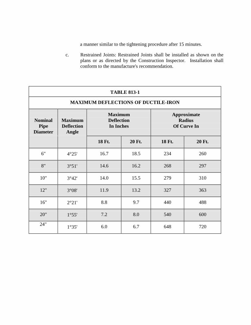
a manner similar to the tightening procedure after 15 minutes.
c. Restrained Joints: Restrained Joints shall be installed as shown on the plans or as directed by the Construction Inspector. Installation shall conform to the manufacture's recommendation.
TABLE 813-1
MAXIMUM DEFLECTIONS OF DUCTILE-IRON
Nominal Pipe
Diameter
Maximum Deflection
Angle
Maximum Deflection In Inches
Approximate Radius
Of Curve In
18 Ft.
20 Ft.
18 Ft.
20 Ft.
6"
4°25'
16.7
18.5
234
260
8"
3°51'
14.6
16.2
268
297
10"
3°42'
14.0
15.5
279
310
12"
3°08'
11.9
13.2
327
363
16"
2°21'
8.8
9.7
440
488
20"
1°55'
7.2
8.0
540
600
24"
1°35'
6.0
6.7
648
720
ITEM NO. 814
DUCTILE IRON PIPE
814.1 DESCRIPTION: This item shall consist of Ductile Iron Pipe installation
in accordance with these specifications and as directed by the Engineer. 814.2 MATERIALS: The materials for Ductile-Iron pipe shall conform to
the specifications contained within the latest revision of SAWS Material Specification "Ductile-Iron Pipe", Item No. 05-11, "Gray-Iron and Ductile-Iron Fittings", Item No. 10-10, and "Ductile-Iron Couplings", Item 100-34.
814.3 CONSTRUCTION METHOD:
1. Excavations at Bells and Collars: Ductile Iron pipe shall be
installed as specified within "Water Main Installation", Item No. 812, of these specifications. Bell holes of sufficient size shall be provided at each joint to permit the joints to be made properly. For mechanical type joints, the minimum clearance between the bell and natural ground shall be 6 inches in all directions. Subject to the above provisions, the length of excavation for bell holes below grade of the trench bottom shall be kept to a minimum.
2. Corrosion Protection for Ferrous Pipe, Fittings, and Valves:
Except as otherwise shown on the plans or as directed by the Engineer, anti- corrosion embedment shall be provided for all ductile-iron pipe, fittings, and valves and at all valves, fittings, or outlets for nonferrous or reinforced concrete steel cylinder pipe. The embedding material shall be Modified Grade 5 gravel washed sand which conforms to the requirements as set forth in the Item No. 804, Paragraph 804.4.2.
The preparation of the trench shall be in accordance with applicable provisions of "Excavation, Trenching and Backfilling", Item No. 804. After the subgrade has been prepared, the pipe shall be laid to grade in accordance with "Excavation, Trenching and Backfilling", Item No. 804. The pipe, fitting, or valve shall be firmly embedded in and surrounded by an insulating blanket of the embedding material. The minimum thickness of this blanket shall be 6 inches in every direction.
3. Coating and Wrapping of Underground Pipe:
a. Ductile-Iron Pipe In Casing: Where ductile-iron pipe is to be installed in a bore, the pipe shall be thoroughly cleaned down to the coal-tar enamel pipe coating by approved methods. Where damaged, a prime coat compatible to the polyvinyl tape to be used shall then be applied to the pipe. Following the application of the prime coat, the pipe shall be wrapped with Scotchrap, Trantex V- 10 polyvinyl tape, or an approved equal. The tape shall not be applied until the prime coat is completely dry.
The tape shall be spirally and tightly wrapped on each section of the pipe with a 50% lap. The wrap shall be made to the bell on the bell end and to a point 6 inches from the spigot end. The joint shall be protected with tape 6 inches in width on pipe 12” or less in size and with tape 8 inches in width on pipe greater than 12” in size.
b. Open Trench: Ductile-iron pipe to be installed in a trench shall be
protected in the following manner. Each pipe joint shall be covered with a 4 mil thick polyethylene sleeve that is 2 feet longer than the pipe joint. The sleeve shall cover the full length of the pipe joint, lap over 1 foot on each end of the adjoining pipe joints, and be secured with a minimum of two circumferential turns of pressure sensitive polyvinyl tape. Excess material should be neatly drawn up around the pipe barrel, folded into an overlap on top of the pipe, and held in place by means of pieces of pressure sensitive tape at approximately 5 foot intervals. After assembling the joint, the polywrap tube from the previously installed pipe shall be pulled over the joint and secured by the Contractor. The polywrap tube from the new joint shall be pulled over the first tube and secured by the Contractor to provide a double seal.
Cast-iron and Ductile-iron fittings and valves shall be completely wrapped in 8 mil thick polyethylene film with a minimum of one 1 foot overlap on each end and appropriately taped. Laps shall cover joints with adjoining pipe joints or fittings when installed. Fire Hydrant barrel from the surface to the valve shall be wrapped as specified herein.
Any damaged areas in the polyethylene film shall be repaired by covering the area with a sheet of polyethylene film large enough to
lap over the damaged area 1 foot minimum in any direction and appropriately taped. Extreme care shall be taken at service tap locations to insure that the tape extends beyond the corporation and onto the service line pipe 1 foot.
Prior to placing pipe in the trench, a cushion of approved materials shall be placed in the trench as required by "Excavation, Trenching and Backfill", Item No. 804. Backfill material shall be carefully placed on the pipe so as to avoid any damage to the polyethylene sleeve.
The Contractor shall use care to protect and preserve the polyethylene wrap around ductile iron water mains when installing service corporations. The required method is to wrap pipe tape around the pipe over the polywrap in the area to be tapped. The tap is to be made through the tape and polywrap. It is not necessary to remove and replace poly wrap. All exposed pipe, the corporation, and the first 3 feet of the service shall be wrapped and taped to achieve a complete seal. In addition, a sand envelope shall extend over and around the connection to a depth of eight inches above the main.
c. Protective Coating on Joints: All bolts and nuts destined for
underground service on valves, fire hydrants, cast-iron mechanical joint fittings, pipe joints, and other ferrous metal appurtenances shall be packed in an approved protective coating material after installation. After the joint has been made and bolts drawn to the proper tension, the joint including glands, flanges, bolt heads, and nuts shall be covered with an approved SAWS coating or approved. Such protective coating shall be supplemental to anti- corrosive sand embedment as set forth in "Excavation, Trenching and Backfill", Item No. 804. Coating and wrapping of joints will be considered incidental to the installation, and no separate payment will be made for this item. Asphaltic material such as Talcote shall not be used.
4. Cutting Ductile-Iron Pipe: All cuts made on ductile-iron pipe shall be
done with a power saw or approved mechanical cutter. The cuts shall be made at right angles to the pipe axis and shall be smooth. The edges of the cut shall be finished smoothly with a hand or machine tool to remove all rough edges.
5. The outside edge of pipe should be finished with a small taper at an angle of
about 30 degrees.
ITEM NO. 816
STEEL PIPE INSTALLATION
816.1 DESCRIPTION: This item shall consist of steel pipe installation in
accordance with these specifications and as directed by the Engineer. 816.2 MATERIALS: The materials for steel pipe shall conform to the
specifications contained within the latest revision of SAWS' Material Specification, "Steel Pipe", Item No. 05-30.
816.3 CONSTRUCTION:
1. General: Steel pipe shall be installed as specified within "Water
Main Installation”, Item No. 812 of these specifications. The Contractor shall furnish all steel piping including fittings, couplings, specials, pipe supports, eyebolts, nuts, and accessories which are shown on the plans and as required for proper connection to existing piping. The Contractor's attention is directed to the fact that the exact location and elevation of existing piping must be determined in the field prior to fabrication of connecting piping.
All steel pipe and specials may be either mill pipe or fabricated pipe and, in either case, shall be fabricated to the sizes, dimensions and shapes as indicated on the plans and as shown on the plans. Unless otherwise indicated on the plans, all steel pipe, bends, or specials shall have an outside diameter minimum wall thickness and unit weights as shown in Standard Drawing DD-856-01.
Any pipe section, fitting, or special which shows dents, kinks, abrupt changes of curvature other than specified, or any other damage will be rejected. Any pipe section, fittings, or special section that has been dropped from a truck or crane will be rejected. The Contractor shall, at his expense, replace or recondition each rejected section. Reconditioning procedures must be acceptable to the Engineer.
2. Ends of Sections: Ends of pipe sections, bends, and specials shall be beveled for field welding, unless shown otherwise on the plans.
3. Seams: All piping shall be made from steel plate rolled into cylinders or sections thereof, with not more than two longitudinal butt welds, or
shall be spirally formed and butt welded. Girth seams shall be butt welded and shall not be closer than 6 feet apart except in specials and bends.
4. Length Tolerance: Standard and special sections shall be within 1/16 inch
(plus or minus) of the specified or theoretical lengths.
5. Welded Joints: Except where ends are shown on the plans to be joined by mechanical couplings, all joints for steel pipe installed on the bridge structure and in open trench shall be welded.
Welders appointed to do welding on steel pipe shall be certified with 4F and 5G certification. All welds shall be sound, free from embedded scale and slag, shall have a tensile strength across the weld not less than that of the thinner of the connected sections, and shall be watertight. Butt welds shall be used for all welded joints in line-pipe assemblies and in the fabrication of bends and other specials. All welds shall be subject to Pre- Manufacturing inspection and available by request.
Welding for field joints shall conform to the applicable requirements of the AWWA "Standard Specifications for Field Welding of Steel Water Pipe Joints, C206." Parties involved in the construction of main(s) shall pay special attention to the AWWA "Standard Specifications for Field Welding of Steel Water Pipe Joints, C206, “Control of Temperature Stresses”. After welding, the joints shall be prepared, primed, and painted, or wrapped in accordance with "Protective Coating", Item No. 816.3.6 of these Specifications.
Leaks in welds shall be repaired by chipping out the defective material and re-welding. No hammering will be permitted.
6. Protective Coatings: All steel pipe, bends, and specials shall be prepared,
primed, painted, or wrapped in the field as specified herein.
a. Exterior Surfaces Above Ground: Exterior surfaces of all new pipe and appurtenances installed shall be thoroughly cleaned to bare metal by high speed wire brushing, scraping, or other suitable methods approved by the Engineer, given a single coat of industrial grade, rust inhibitive primer, and two finish coats of aluminum paint.
b. Exterior Surfaces Underground: Exterior surfaces of all steel pipe,
bends, and specials which are to be installed in open trench shall
be thoroughly cleaned to bare metal by high speed wire brushing, scraping, or other suitable methods approved by the Engineer, given a single coat of rust inhibitive primer, and wrapped with polyvinyl tape in accordance with AWWA C203-91, "Protective Coatings for Steel Water Pipelines," (Appendix C).
c. Buried Couplings: Mechanical couplings which are to be installed
underground shall be protected in accordance with "Protective Coatings", Item No. 816.3.6 of these Specifications.
d. Field Welded Joints: After installation of pipe, bends, and
specials, all ends of pipe adjacent to welded field joints, including the weld proper, shall be cleaned, primed, painted or wrapped as specified for the pipe adjacent to the weld.
e. Interior Surfaces: The interior surfaces of all steel pipe, fittings
and specials shall be cleaned by sandblasting and then primed and coated in the shop with coal tar enamel.
7. Trench, Bedding and Backfilling: All trenching, bedding and backfilling
for steel piping to be laid in open trench shall be in accordance with the requirements specified for Concrete Steel Cylinder Pipe in according with Item No. 848.2.7.
ITEM NO. 822 CUSTOMER’S YARD PIPE (WATER)
822.1 DESCRIPTION: This item shall consist of Customer yard piping adjustments
and installation in accordance with these specifications and as directed by the Engineer.
822.2 MATERIALS: The materials for Customer yard piping adjustments and
installation shall conform to the specifications contained within the latest revision of SAWS' Material Specification "Copper Tubing", Item No. 15-01 and "Brass Goods", Item No. 15-40.
822.3 CONSTRUCTION:
1. Designation of Yard Piping: New copper yard piping shall be installed
within the limits of the Customer's property in conjunction with all small service lines relocated from existing mains in the alleyways behind Customer residences to street rights-of-ways fronting Customer residences.
See Standard Drawing DD-822.
Customer yard piping begins from the outlet meter connection to the point of connection within the limits of the Customer's lot or property.
"Short yard piping," shall be described as consisting of Customer's yard piping that does not exceed one-half the depth of the lot.
"Long yard piping," shall be described as consisting of Customer's yard piping that when installed exceeds one-half depth of the lot.
2. Materials: All ¾ through 2 inch yard piping shall be furnished by the
Contractor and shall be Type "K", soft annealed copper water tubing. Plastic round Customer's cut-off valve boxes furnished by the Contractor shall consist of a box and cover, shall accommodate cut-off valves up to 2 inches, and shall be by an approved manufacturer.
The Contractor shall also furnish all materials to include pipes, nipples, unions, couplings, tees, elbows, street ells, hose bibs, insulation for riser pipe, caps, plugs and appurtenances required to complete the tie of
Customer's new yard piping at the new point of connection and the abandonment of the Customer's old yard piping at the old point of connection, as no separate pay item. Where dissimilar materials are tied together, the Contractor shall install a PVC Schedule 80 insulator coupling.
3. Installation: Work involved with replacing existing yard piping shall consist
of several key components as listed:
• Excavation of miscellaneous material encountered • Installation of the new copper yard piping with 12 inches of cover
minimum and in the most direct and practicable alignment • Brass fittings • Customer's cut-off valve and the Customer's cut-off valve meter box • Reconnection of the Customer's service at the relocated meter and the
new point of connection within the limits of the Customer's property • Abandoning the Customer's old yard piping by cutting and plugging
the old yard piping at the old point of connection within the limits of the Customer's property
• Backfilling the trench with approved selected material and disposal of surplus excavated material
• Replacement of surfaces of all types over the completed yard piping trench with approved selected material and disposal of surplus excavation material
• Restoration of the site. Existing trees and shrubbery within the Customer’s property shall not be disturbed.
When the presences of manifold systems are encountered, the Contractor shall install and tie-in Customer yard piping at the existing point of connection. Lawn sprinklers are a possible indication of existing manifold systems. All exposed risers shall be protected from freezing temperatures by means of keeping them no less than 6 inches below ground surface to the tie-in. Trench excavation may be accomplished either manually, mechanical "Ditch Witch" or by similar mechanical trenching equipment. If mechanical trenching equipment is utilized, depressions or damage to lawn areas caused by crawler track pads or pneumatic tires shall be repaired and restored to their original condition.
Lawn turf over the trench shall be removed squarely to a depth of 2 inches and in lengths not to exceed 36 inches. Lawn turf removed and material excavated from the trench area shall not be placed directly upon existing
lawn turf areas, but rather, they shall be separated and placed on building paper, plastic membrane, or approved equal. Placed building paper, plastic membrane, or approved equal shall cover the existing lawn turf adjacent and parallel to the alignment followed by the trench. After the installation of the yard piping, the trench shall be backfilled and adequately tamped in two compacted lifts of 5 inches and watered. The lawn turf shall be replaced, adequately tamped, and thoroughly watered after surplus soil is removed. Customer's yard piping shall be flushed prior to final tie-in at the existing point of connection.
ITEM NO. 823 DIRECTIONAL BORING FOR
CUSTOMER’S YARD PIPE (WATER)
823.1 DESCRIPTION: This item shall govern the furnishing and installation of customer yard piping and conduit by the method of directional boring as shown on the plans and in conformity with this specification.
823.2 MATERIALS:
1. The materials for customer yard piping installation and adjustment shall conform to the specifications contained within the latest revision of SAWS’ Material Specification, “Copper Tubing”, Item No. 15-01 and “Brass Goods”, Item 15-40.
2. The Polyvinyl Chloride (PVC) conduit shall be Schedule 80 or Certa T- Lock PVC where applicable and shall conform to ASTM D 1785. The fittings for the PVC pipe shall be Schedule 80 and shall be in accordance with ASTM D 2467.
823.3 CONSTRUCTION:
1. Determination for Directional Boring Method – Directional boring method shall be used for installations of customer’s “short yard piping” or “long yard piping” when open-cut method is not feasible. Refer to Standard Specification “Designation of Yard Piping”, Item No. 822.3.1. Directional boring method should be used to avoid disruption to landscaping, trees, driveways, retaining walls, privacy walls, structures, or sprinkler systems that cannot be economically be replaced, or as directed by the Construction Inspector. The yard piping shall be placed in 2 inch or 4 inch Inside Diameter (I.D.) PVC conduit as appropriate when directed by the Construction Inspector.
2. Designation of Yard Piping: Refer to Standard Specification Item
No. 822.3.1
3. Materials: Refer to Standard Specification Item No. 822.3.2
4. Installation: Directional Boring Method machine as manufactured by “Ditch Witch” or “Vermeer” or equal, capable of drilling minimum of 300 feet continuous bore.
Refer to Standard Specification Item No. 822.3.3 for installation procedures for customer yard piping. Directional boring shall be completed with the use of a directional boring machine, as manufactured by “Ditch Witch”, “Vermeer”, or equal. The directional boring machine shall be supplied with an output signal inside the housing of the drill bit. The output signal shall have a constant output signal to allow a person to track the location of the beacon at all times. The drill bit shall be located a maximum of every 5 feet for exact location of the service line to be pulled in. When bore is completed, contractor shall provide the City of Cibolo with a pilot of the bore path.
The drilling machine shall be set up at such a location to avoid disruption of private yard and landscaping. The operator of the drilling unit shall check the bore path and position of boring pit at every five feet and make necessary correction to stay along the alignment. The pilot hole shall not be greater than 4 inches in diameter, except when a 4” PVC conduit is installed. The Contractor shall make necessary provisions to keep water and soil out of the installed yard piping.
The drilling machine shall be equipped with a drilling fluid compatible for the on- site conditions. The fluid, such as bentonite, shall be used for lubricating the pipe during pull-back, forcing spoils out of the pipe pit, assisting in holding the hole open during pull back, and hardening into a clay substance around the outside of the conduit, preventing settlement of the ground. Adequate drilling fluids shall be used to avoid a “hydra-lock” condition. The directional head shall be capable of accepting a variety of cutting bits for varied soil conditions.
Any damage to customer’s property, landscaping or trees caused by Contractor’s operation for installation of yard piping, shall be replaced to the customer’s and City of Cibolo satisfaction at no additional cost to the City of Cibolo.
Contractor shall take a video DVD recording of the customer’s yard prior to commencing any work in the area. A DVD video shall be turned into the City of Cibolo before starting work.
ITEM NO. 824 SERVICE SUPPLY LINES (WATER)
824.1 DESCRIPTION: This item shall consist of water service supply lines adjustment and installation in accordance with these specifications and as directed by the Engineer.
824.2 MATERIALS: The materials for water service supply lines installation and adjustment shall conform to the specifications contained within the latest revision of SAWS Material Specification "Brass Gate Valves", Items No. 21-10, "Brass Goods", No. 15-40, "Copper Tubing", No. 15-01 and "Service Saddles", Item No. 100-30.
824.3 CONSTRUCTION: 1. General: Service supply lines and fittings, meter boxes and appurtenances
shall conform to the Material Specifications and shall be installed by the Contractor as specified herein, or as directed by the Engineer and in accordance with the Standard Drawings DD-824-Series.
2. Designation of Service Supply Lines: A service supply line located between the water main and the inlet side of the water meter is designated as a "water service line". A service supply line located between the outlet side of the water meter to the point of connection within the limits of the Customers lot or property is designated as "Customer's yard piping" and is covered under Item No. 822 of these Specifications. Services 2” and smaller are designated "small services"; services 4” and larger are designated "large services".
3. Service Relays: New transfer main(s) to which services are to be relayed and are on the same side of the streets as the Customer's meter are defined as "short relays". New transfer main(s) to which services are to be relayed and are on the opposite side of the street from the Customer's meter are defined as "long relays".
Service Reconnects: New transfer main(s) to which services are to be reconnected and on the same side of the street as the old main are defined as "service reconnects". Existing services on the opposite s ide of the street to the new main shall be defined as a "long relay".
4. Service Relocates: Service relocates are defined as services that are relocated
from an alley or street to a side or front street. New transfer main(s) to which services are to be relocated and are on the same side of the street as the Customer's new meter box location, are designated as "short relocates". New transfer main(s) to which services are to be relocated and are on the
opposite side of the street from the Customer's new meter box location, are designated as "long relocates".
5. New Services: If a new main is required to be extended to provide water
service for new Customers, the service lines laid to the new main shall be designated as "new services." New laid main(s) to which new services are on the same side of the street as the Customer's new meter box location, are designated as "new short services." New laid main(s) to which new services on the opposite side of the street from the Customer's new meter box location, are designated as "new long services."
6. New Unmetered Services: New Unmetered services are defined as
services that are installed on existing mains or new mains to provide service to Customers platted vacant lots. Where the new main or existing main to which new un-metered services are being installed is on the same side of the street as the Customer's new or existing meter box location, (Inspector to set location of new meter box if no existing meter box is set), the services to be laid are designated "new un-metered short services." Where the new main or the existing water main to which new un-metered services are installed is on the opposite side of the street from the Customer's new or existing meter box location, (Inspector to set location of new meter box if no existing meter box is set), the services to be laid are designated "new un-metered long service". New unmetered long services and new un-metered short services will not include "Customer's yard piping" and no meter will be set.
7. Tap Holes: Tap holes are defined as excavations at existing mains, which are
required in association with replacements of water service lines by pulling, boring or jacking operations.
All backfill material shall be as specified for main and service line trench excavation.
For service lines and tap holes, payment for bedding, initial backfill and secondary backfill shall be included in the various sizes of each service placed.
8. Service Line Installation: Unless otherwise notified, service relays,
Service reconnects, service relocates and new services shall be installed as described herein, and in standard drawing DD-824 Series. Unless otherwise indicated, existing meter and meter box relocation shall be included in the service line installation.
All service line installation shall include a dielectric union to be installed within the meter box on the outlet side of the meter, as shown in Standard
Drawing DD-824-Series.
Cutting, excavation, backfill and replacement of pavement shall be done as specified herein and in accordance with applicable sections of the City of Cibolo Specifications for Utility Trench Excavation, Backfill, Surfacing, and Barricading. The minimum trench width for small service lines shall be 8 inches, while the minimum trench width for large service lines shall be the nominal pipe diameter plus 16 inches, except when specified otherwise by the Engineer. For ¾” to 2" Service lines, minimum bury depth shall be 3 feet. For services greater than 2”, minimum depth of bury shall be 4 feet.
All service lines shall be installed in accordance with City of Cibolo Standard Drawing DD-824 Series, SAWS Standard Material Specification Item No. 100-30, except that two strap service saddle clamps shall be installed for all tap connections made on water mains located within boundaries of Pressure Zones (formally known as Service Levels) 9 through 16.
The Contractor shall use precaution to protect and preserve the polyethylene wrap around Ductile-Iron (DI) water mains when installing service corporations. The required method is, wrap pipe tape around the pipe, over the polywrap, in the area to be tapped. The tap shall be made through the tape and polywrap. It is not necessary to remove and replace polywrap. All exposed pipe, corporation and the first three feet of the service, shall be wrapped and taped to achieve a complete seal. In addition, a sand envelope shall extend over and around the connection to a depth of 8 inches above the main.
Small service lines shall be embedded in sand in accordance with "Excavation, Trenching and Backfill", Item No. 804.
Where approved by the Construction Inspector, the Contractor may lay the new service line from the corporation stop to the curb stop or angle valve. Upon completion, the Contractor shall isolate the new service line by closing the curb stop or angle valve until the meter box is set.
9. Splicing. A long service line single slice may be permitted by means of a
3-part compression or flared coupling only when approved in advance by the Engineer, provided the location of the splice is not under pavement or concrete. The segment added is required to be the same material as the existing service line, unless otherwise directed by the Engineer. Splicing short service lines will not be permitted.
10. Boring or Jacking Service Lines: Service lines which cross paved streets may
be installed at the Contractor's option by boring or jacking operations. Where it becomes necessary to widen the main trench section to accommodate a bore
pit, such widening shall not extend more than one additional foot into the traffic side of the street.
11. Tapping Asbestos Cement (AC) Water Mains: All necessary service line
tapping of AC pipe shall be completed during the period immediately before or after hydrostatic pressure testing operations so that subsequent flushing will maximize the elimination of contaminants associated with the tapping process.
Tapping of AC pipe must be done in accordance with manufacturers’ recommendation and done only with tap machine having a built in flush valve and the flush valve must be open during the entire procedure.
12. Abandonment of Service Lines: The Contractor shall accomplish all
cutting, capping, and plugging necessary to isolate new service lines transferred to new and existing mains from those abandoned, including service lines designated on the plans as "tap plug" and "tap kill." The corporation stop for an abandoned service line tapped on a ferrous main shall be removed, and the tap at the main shall be plugged with an appropriately sized brass plug. For a non-ferrous main, the corporation stop shall not be removed from the main. Instead, the corporation stop shall be closed and the flared nut shall be removed from the corporation stop. After the appropriately sized copper disc is inserted inside the flared nut, replace the flared nut on the corporation stop. The Contractor shall salvage copper service line tubing, brass fittings, and other materials as directed by the Construction Inspector and return them to the Owner.
13. Tapping PVC (C-900): Tapping of PVC must be done in accordance with
Uni-Bell procedures. Direct Tapping will not be allowed. All drill cutting tools must be the "shell type" with internal teeth or double slots which will retain the coupon. The shell cutters must be designed for C-900 pipe, thus having sufficient root depth to handle the heavier walled pipe.
14. Small Service Lines: Copper tubing shall be used for ¾” through 2” service
lines. Brass fittings for ¾” and 1" service lines shall be of the flared or compression type for the use with Type 'K' soft annealed copper tubing. Brass fittings for 1½" and 2" lines shall be of the flared or compression type for use with type 'K' soft annealed copper tubing, except as modified by "Splicing", Item No. 824.3 8.
Copper tubing shall be cut squarely by using an approved cutting tool & by avoiding excessive pressure on the cutting wheels which might bend or flatten pipe walls. Following the copper tubing cut, but before flaring, a reamer shall be used to remove the inside rolled lip from the tubing. Flared ends shall be expanded by the use of a flaring tool using care to avoid splitting, crimping,
or overstressing the metal. Pipe adjacent to the fittings shall be straight for at least 10 inches. Bending of tubing shall be accomplished by using an appropriate sized bending tool. No kinks, dents, flats, or crimps are permitted, If such should occur, the damaged section shall be cut out &replaced. When compression fittings are used, copper tubing shall be cut squarely prior to insertion into the fitting. Final assembly shall be in accordance with the manufacturer's recommendations.
15. Small Service Lines on New Mains: Installation of new copper service lines shall consist of all excavation through miscellaneous material encountered; trench excavation protection; drilling and tapping the new main with an approved tapping machine; setting the curb stop or angle valve at the meter; laying the new copper service line at the specified depth between the main and the meter and its tie-in at the corporation and the curb stop or the angle valve; relocating the existing meter and installing a new meter box where required in accordance with "Meter and Meter Box Installation", Item No. 833, herein; backfilling the trench with approved selected material and disposal of surplus excavated material; capping the tap hole with asphalt treated base, including the outer limits of the main trench line with service line trench; cutting and replacing pavements, curbing and sidewalks of all types over the limits of the main line trench and the completed service line trench.
16. Reconnecting Service Lines: Both old and new water mains at existing service line connections as shown on the plans shall be exposed. The old main shall be exposed for the purpose of gaining access to the existing service corporation stop and the new main for the purpose of installing the new corporation stop. The new main shall be exposed for the purpose of being drilled and tapped with an approved tapping machine, a new corporation stop installed under pressure, and the trench extended laterally To expose a sufficient length of the existing service line to provide slack to bend it into position for tying to the new corporation stop. After suitable notification to the Customer, the Contractor shall "kill" the existing service by closing the corporation stop, removing the existing flare nut, inserting inside the existing flared nut an appropriately-sized copper disc and replacing the existing flared nut on the corporation stop if the main is non-ferrous, or plugging the existing service line at the main if the main is ferrous. The Contractor shall then immediately open the stop and restore water service to the Customer. Where it is not possible to obtain sufficient length in the existing service to tie directly to the new main, at the direction of the Engineer, the Contractor shall splice the necessary length of new tubing and tie it to the existing service by means of a compression coupling at a point as close as practicable to the new main.
Cutting and bending of the tubing, introduction of slack to compensate for soil
movement, and completion of the installation shall be as specified in "Relaying Service Lines", Item No. 824.16.
Where old &new mains are on opposite sides of a street, service lines may be installed under the pavement by boring rather than trenching.
17. Relaying Service Lines: The existing or new mains shown on plans shall be exposed opposite location stakes placed on site at the direction of the Engineer. The existing or new main shall; be drilled and tapped with an approved tapping machine, a new corporation stop installed, and the trench extended laterally to the location specified for the meter box. The existing meter shall be reset and the meter box and base shall be installed at its staked location and perpendicular to the corporation stop in the water main. The meter box location shall not vary more than 24 inches in any direction from its staked location. The service line shall be installed with sufficient slack to compensate for soil movement. Where the location of the existing meter is not changed, the new service line shall be extended from the main to the existing meter, a new curb stop installed at the end of the service line, and connected to the inlet side of the meter. If disturbed, the existing meter box shall be reset to correct grade. Long service relays may be placed under the street pavement by boring or jacking rather than trenching.
18. Single Service Line - Dual Meters: The single service line - dual meter installation shall consist of a 1" copper service line reducing to two ¾” copper service lines at a tee which shall be set in line with the front edge of meter boxes for ⅝” and ¾” meters. A single service line with dual meters shall be installed in those new residential developments where new ⅝” and ¾” meters are required and in main replacement work where it is necessary to change the location of existing ⅝” and ¾” meters. Single service line - dual meter materials and installation requirements shall conform to requirements established herein (See Drawing DD824-05.).
19. Small Service Lines on Existing Mains: The work involved in the
installation of new copper service lines on existing mains shall consist of jacking, boring, tunneling, and, where authorized, open trench operations; all excavation through whatever material encountered; trench excavation protection; using the existing corporation when approved by the Construction Observer/Inspector; tapping the existing main and installing the new corporation and setting the curb stop or angle valve at the meter; relocating the existing meter and installing a new meter box where required in accordance with "Meter and Meter Box Installation", Item No. 833, herein; abandoning the existing corporation stop, removing the existing flared nut, inserting inside the existing flared nut an appropriately sized copper disc and replacing the existing flared nut on the corporation stop if the main is non-ferrous, or plugging the existing service line at the main if the main is
ferrous; installing the new service line at the same grade as the existing service line or at the specified grade between the main and the existing meter and its tie-in at the corporation and the curb stop; disposal of surplus excavated material; capping the tap hole with asphalt treated base including the outer limits of the main line trench and the service line trench; cutting and replacing all surfaces of whatever type encountered over the completed service line trench; restoration of the site.
20. Large Service Lines: DI pipe and cast-iron fittings used for metered
service lines and non-metered fire service lines larger than 2” shall be installed in accordance with the applicable provisions of "Water Main Installation", Item No. 812, except where otherwise approved by the Engineer.
21. Large Service Lines on New Mains: Work involved in the installation of a new
metered service lines and non-metered fire service lines shall consist of all excavation through whatever material encountered; trench excavation protection, installing tees, pipe and fittings of various sizes including main line and service line valves, valve boxes, DI pipe, fittings, in accordance with DD-824 “Service Standards” and reaction block required; backfilling with approved selected material; cutting and replacing pavements, curbing, and sidewalks of all types over the limits of the main line trench and the completed DI service line.
22. Large Service Lines on Existing Main: The work involved in the installation of the new metered service lines and non-metered fire service lines shall consist of all excavation through whatever material encountered, trench excavation protection, cutting-in tees and installing tapping sleeves and valves, pipe and fittings of various sizes including main line and service valves; valves boxes, DI pipe, fittings and reaction block required; backfilling with approved selected material; cutting and replacing pavements, curbing, and sidewalks of all types over the limits of the main line trench and the completed DI service line.
ITEM NO. 826 VALVE BOX ADJUSTMENTS
826.1 DESCRIPTION: This Item shall consist with the adjusting of existing valve
boxes in accordance with these specifications and as directed by the Engineer. 826.2 MATERIALS: The materials for valve boxes shall conform to the specifications
contained within the latest revision of SAWS Material Specifications "Valve Boxes", Item No. 10-20.
1. Construction Method: The valve box shall be placed in such a manner to
prevent shock or stress from being transmitted to the valve. It shall be centered and plumb over the operating nut of the valve with the box cover flush with the surface of the finished pavement or at such other level as may be directed by the Engineer. Valve boxes located in streets or other area subject to vehicular traffic shall be provided with concrete collars as shown in the Standard Drawings DD-828 Series. Collars around such valve boxes shall be formed and finished off neatly and in a workmanlike manner.
Valve box shall be located so that the valve operating nut is readily accessible for operation through the opening in the valve box. The valve box shall be set flush with the surface of the finished pavement or at such other elevations as may be specified. Pits shall be constructed so that it permits minor valve repairs and provides the valve and pipe protection from impact where they pass through the pit walls.
2. Existing valve box: Existing valve boxes shall be defined as boxes which
are located within the right-of-way of the specified area of construction operations and are in conflict. These boxes shall be adjusted to match proposed finished grades.
Valve boxes installed as part of a new valve and mainline construction project are considered "new valves." Adjustments to “new valves” are incidental to the installation of the valve and are paid for as part of Item Nos. 828, 830 or 832 of these Specifications.
ITEM NO. 828 GATE VALVES
828.1 DESCRIPTION: This item shall consist of gate valves installed in accordance
with these specifications and as directed by the Engineer. 828.2 MATERIALS: The materials for all gate valves shall conform to the
specifications contained within the latest revision of SAWS Material Specification "Resilient Seated Gate Valves", Item No. 21-02 and AWWA with the exception that fusion bonded coating epoxy will be the only coating allowed.
828.3 CONSTRUCTION: Gate valve installation shall include; valve, reaction
blocking when required conforming to Standard Drawing DD-828-1, cast iron boot, valve box extension (Ductile Iron Riser Pipe), valve box, concrete collar where subjected to vehicular traffic, and valve box lid. Gate Valves constructed in terrace shall be constructed with No. 3 bars all around.
The valve box shall be placed in such a manner to prevent shock or stress being transmitted to the valve. All valves located 6 feet and deeper shall include valve key extensions inside the valve box. The Contractor has the option to install fully adjustable valve box and valve key extension systems, on all valves located between 6 feet and 13 feet. Adjustable valve box and valve key extension systems shall be centered over the valve’s operating nut with the box cover flush with the finished pavement surface or located at another level as directed by the Engineer. Valve boxes located in streets or other area subject to vehicular traffic shall be provided with concrete collars as shown in the Standard Drawings. Collars around such valve boxes shall be formed and finished off neatly and in a workmanlike manner.
Valve pits shall be located so that the valve operating nut is readily accessible for operation through the opening in the valve box. The valve box shall be set flush with the finished pavement surface or at other finish elevations as may be specified. Pits shall be constructed in such a manner to permit minor valve repairs and provide protection to the valve and pipe from impact where penetrating through pit walls.
In a High Pressure Distribution System as specified in Appendix A, all valves 6 inches and larger, shall be supported on a concrete pad in accordance with Standard Drawings DD-828-2 and DD-828-3.
ITEM NO. 830
BUTTERFLY VALVES 830.1 DESCRIPTION: This item shall consist of butterfly valves installed in
accordance with these specifications and as directed by the Engineer. 830.2 MATERIALS: The materials for all butterfly valves shall conform to the
specifications contained within the latest revision of SAWS' Material Specification, "Hand - Operated Butterfly Valves", Item No. 21-05 and AWWA with the exception that fusion bonded coating epoxy will be the only coating allowed.
830.3 CONSTRUCTION: Butterfly valve installation shall include; butterfly valve,
coated and wrapped steel pipe nipple with reaction stop ring, concrete reaction blocking, cast-iron boot, valve box extension (ductile iron riser pipe), valve box and lid, concrete collar where subjected to vehicular traffic, all couplings and all coupling adapters required to complete the connection. The entire valve except for the operating nut shall be coated with an approved SAWS sewer structural coating, and wrapped with Polywrap. Butterfly Valves constructed in terrace shall be constructed with No. 3 bars all around.
The valve box shall be placed in such a manner to prevent shock or stress being transmitted to the valve. All valves located 6 feet and deeper shall include valve key extensions inside the valve box. The Contractor has the option to install fully adjustable valve box and valve key extension systems on all valves located between 6 feet and 13 feet. Adjustable valve box and valve key extension systems shall be centered over the valve’s operating nut with the box cover flush with the finished pavement surface or located at another level as directed by the Engineer. Valve boxes located in streets or other areas subject to vehicular traffic shall be provided with concrete collars as shown in the Standard Drawings DD-830 Series. Collars around such valve boxes shall be formed and finished off neatly and in a workmanlike manner.
ITEM NO. 831 CUT-IN TEE
831.1 DESCRIPTION: This item shall consist of cut-in tees (Tee of various types and
sizes) installed in accordance with these specifications and as directed by the Engineer.
831.2 MATERIALS: The materials for cut-in tees shall conform to the specifications
contained within the latest revision of SAWS Material Specification for all appropriate items.
831.3 CONSTRUCTION: The work involved in cutting in a tee shall consist of the
following; excavation, shut-down and isolation of existing main to which the new main is to be connected, cutting pipe for the connection, dewatering the excavation, customer notification of service interruption where required, installation of all pipe used to complete the connection, all necessary tie-ins (connections to existing or new main), fittings, approved reaction blocking required and backfilling the excavation with approved selected materials or flowable backfill if required. Where the installation of a valve is required, payment will be made in accordance with, “Gate Valves”, Item No. 828 of these Specifications.
The processes of cutting and replacing the following; pavements (any type), curbs, sidewalks, backfilling to exiting grade, flowable backfill if required and sodding for the installation of a Cut-in tee will be considered subsidiary to the work and must comply with the applicable TxDOT Specification or City of Cibolo Specifications and applicable street cut policies.
ITEM NO. 832 TAPPING SLEEVES AND VALVES
832.1 DESCRIPTION: This item shall consist of tapping sleeves and valves installed
in accordance with these specifications and as directed by the Engineer. The use of size on size taps shall not be permitted. Only cut-in tees shall be used within the system unless otherwise approved.
832.2 MATERIALS: The materials for tapping sleeves and valves shall conform to the
specifications contained within the latest revision of SAWS' Material Specification, "Tapping Sleeves", Item No. 100-35 and "Resilient Seated Gate Valves and Tapping Valves", Item No. 21-02.
832.3 CONSTRUCTION: The installation work involved in tapping sleeves and valves
shall consist of; excavation, backfilling the excavation with approved selected material, tapping sleeve, approved reaction blocking conforming to Standard Drawing DD-839, tapping valve, valve box assembly, concrete collar where subjected to street traffic, and cast iron lid. New taps will not be permitted closer than 2 feet of a joint or existing tap. The use of a shell type cutter shall be required when tapping sleeves and valves. Whenever working on potable or recycle water systems, the shell cutter shall be disinfected with bleach prior to start of work. The cutting edge shall be sharp and round. Any defective cutters shall be rejected by the Inspector.
All the tapping sleeves shall be air tested to 50 psi prior to tapping the main line.
The valve box shall be placed in such a manner to prevent shock or stress from being transmitted to the valve. Valve boxes shall be centered over the valve’s operating nut with the box cover flush with the finished pavement surface or located at another level as directed by the Engineer. Valve boxes located in streets or other areas subject to vehicular traffic shall be provided with concrete collars as shown in the Standard Drawings. Collars around such valve boxes shall be formed and finished off neatly and in a workmanlike manner.
ITEM NO. 833 METER AND METER BOX INSTALLATION
833.1 DESCRIPTION: This item shall consist of meter and meter box installation and
adjustment installed in accordance with these specifications and as directed by the Engineer.
833.2 MATERIALS: The materials for meter and meter box installation and
adjustment shall conform to the specifications contained within the latest revision of SAWS' Material Specification "Meter Boxes", Item No. 10-30.
833.3 CONSTRUCTION:
1. Physical movement of existing meters and meter boxes to new locations
may be required where service lines are transferred to new mains in conjunction with main replacement work. Unless specified otherwise, the Contractor shall move existing meters and meter boxes and reconnect and adjust customer's yard piping as part of transferring service lines. A dielectric coupling PVC schedule 80 shall be installed within the meter box between the meter and the customer's yard piping.
Round and oval meter boxes with round covers shall be salvaged and returned to the Owner by the Contractor. The Contractor shall also replace the salvaged meter boxes with the new, appropriately styled oval plastic meter box with oval cover, or rectangular meter box. Unless otherwise specified, the old service line shall be abandoned after the existing meter has been reset in the existing or new meter box.
Where meter boxes are installed in sidewalks or driveways, the Contractor shall install a number one meter box (2 pieces) as shown in the Material Specifications Item No. 10-30 and Standard Drawings DD-833 Series.
New meters will be set by the Owner where mains are extended and new services lines are installed for new or initial customer service. In lieu of the new meter, the Contractor shall furnish and install a meter template in accordance with Standard Drawings DD-833 Series.
Meter and meter box configuration, shall have the meter set horizontal, approximately 6 inches below the top of meter box, so that the meter is above the bottom of the meter box and in-line with the meter box lid opening. The top of the meter box shall be flush with the existing ground surface. All excess soil above the meter coupling, meter flange and meter nuts inside the meter box shall be removed so that the meter register is
clearly visible. The Contractor shall exercise special precautions during excavation at the existing meter location in order to minimize the disturbance of the customer's yard piping. However, if the existing meter elevation is low, the Contractor shall raise the existing meter to conform to the correct configuration indicated herein. Adjustment of meter to proper grade is incidental to the construction and will not be paid for separately.
Where required, pressure reducing valves shall be installed by the customer in accordance with the Uniform Plumbing Code and shall be placed beyond the outlet side of the meter, but not within the Owner's meter box. The pressure reducing valve shall be the property of the water user who will be responsible for its installation, maintenance, and replacement as required.
2. The meter box adjustment shall not exceed 10 linear feet from the
existing box.
ITEM NO.
834 FIRE
HYDRANTS 834.1 DESCRIPTION: This item shall consist of fire hydrant installations using
joint restraints in accordance with these specifications and as directed by the Engineer with the construction plans.
834.2 MATERIALS: The materials for fire hydrant installations shall conform to
the specifications contained within the latest revision of SAWS’ Material Specification, “Specifications of Pipe Joint Restraint Systems”, Item No. 95-10 and SAWS’ Material Specification “Fire Hydrants”, Item No. 21-30.
834.3 CONSTRUCTION:
1. General: Hydrants shall be connected to mains as shown on plans
or as directed by the Engineer. They shall be installed in accordance with Drawing DD-834-01 for joint restraints, Standard Drawing DD-834-02, and Standard Drawing DD-834-03. Hydrants shall also be installed in a location where there is accessibility and in a safe location where there is a minimum possibility of damage from vehicles or injury to pedestrians. In situations where hydrants are placed directly behind curbs, hydrant barrels shall be set so that no portion of the hydrant will be less than 12 inches nor more than 7 feet from the back of the curb. Where hydrants are set in the lawn spaces between the curb and the sidewalk or between the sidewalk and the property line, no portion of the hydrant or nozzle cap shall be within 6 inches of the sidewalk.
Setting final grade of fire hydrants to match proposed or existing field conditions is the responsibility of Contractor.
Hydrants shall be set in accordance with Standard Drawing DD-834-01 for joint restraints, Standard Drawing DD-834-02, and Standard Drawing DD-834-03 for Water Works Construction and shall be set plumb and shall have their nozzles parallel with or at right angles to the curb with the pumper nozzle facing the curb. Drainage and concrete pads shall be provided at the base of hydrants as specified. No fire hydrant drainage system or pit shall be connected to a storm or sanitary sewer.

The Contractor shall install anchored or flanged style fittings in accordance with Standard Drawing DD-834-01, Standard Drawing DD- 834-02, and Standard Drawing DD-834-03.
2. Restrained Joints: Restrained mechanical joints that require field welding
or groove cuts into the pipe barrel for restraint will not be accepted. Restrained joints shall be furnished for pipe at all changes in direction as indicated on the plans, details, or as directed by the Engineer. Restrained mechanical joints shall be locked mechanical joints. All joints shall conform to the San Antonio Water System Material Specification “Pipe Joint Restraint Systems”, Item No. 95-10. The restraint system shall be capable of a test pressure twice the maximum sustained working pressure of 350 psi for ductile iron pipe and pvc.
3. Replacing and Relocating Existing Fire Hydrants: When existing fire
hydrants are to be replaced or relocated, the work shall be accomplished by either of the following:
(1) Cutting or installing a tee of the size and type as indicated on the plans
or as directed by the Engineer. (2) Using a tapping sleeve and valve of the size and type as indicated on
the plans to install a new fire hydrant to an existing or new water main. Size on size taps will not be permitted.
(3) Relocating the existing fire hydrant by closing the existing fire hydrant branch valve, removing the existing fire hydrant, extending the fire hydrant branch and installing the existing fire hydrant as specified herein.
The Contractor shall salvage the existing fire hydrants and other materials as designated in the field by the Construction Inspector and shall deliver this material to the City of Cibolo materials storage yard. Fire hydrant branches shall be abandoned by cutting and capping the fire hydrant cast-iron tee at the service main and surface restored to its original condition.
After a fire hydrant has been set, hydrants shall be painted with a suitable primer and finished with oil-based aluminum paint from the top of the hydrant to a point 18-20 inches below the center line of the pumper nozzle and applied to all exposed metal surfaces above the hydrant base flange. The payment for fire hydrant painting shall be included in the unit cost for installing the fire hydrant.
4. Installation on Water Mains: Ductile Iron (DI) pipe, cast-iron and
ductile iron fittings, and valves used in the placement of fire hydrants and connections to the main will be considered part of the fire hydrant installation and not a part of the main construction. No separate payment will be made for this pipe. Hydrants shall be connected to the mains as shown on plans or as directed by the Engineer. Hydrants shall also be installed in a location where there is accessibility and in a safe location where there is a minimum possibility of damage from vehicles or injury to pedestrians.
ITEM NO. 836 GREY-IRON AND DUCTILE-IRON FITTINGS
836.1 DESCRIPTION: This item shall consist of grey-iron and ductile-iron fittings
installation and adjustment installed in accordance with these specifications and as directed by the Engineer.
836.2 836.2 MATERIALS: The materials for grey-iron and ductile-iron fittings
installation shall conform to American National Standard for Ductile-Iron (ANSI)/ American Water Works Association (AWWA) C153/A21.53, Compact Fittings 3-inch through 64-inch and ANSI/AWWA C110/A21.10, Full Body Fittings 3-inch through 48-inch for Water Service and the specifications contained within the latest revision of SAWS’ Material Specification "Grey-Iron and Ductile-Iron Fittings", Item No. 10-10.
836.3 CONSTRUCTION:
1. Fittings: Shall be either restrained mechanical joint compact or flanged
joint unless otherwise specified on the plans or in the contract documents. All mechanical joint compact fittings shall be installed using approved restraining glands in accordance with SAWS Materials specifications # 113-02, no separate payment will be made for these restraining glands. Approved adapters shall be used where necessary to provide a transition between pipes and/or fittings of differing outside diameters. Thrust blocking shall only be utilized, in addition to restraining glands, if specified on the plans, when tying-in to existing non-restrained pipe, or when approved by the Construction Inspector. Anti-corrosion protection consisting of polyethylene sleeve and asphaltic material for ferrous surfaces shall be applied to exterior surfaces of all fittings installed. Anti-corrosion embedment shall be provided as specified in "Excavation, Trenching and Backfill", Item No. 804.
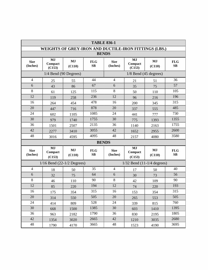
TABLE 836-1 WEIGHTS OF GREY-IRON AND DUCTILE-IRON FITTINGS (LBS.)
BENDS
Size (Inches)
MJ Compact
(C153)
MJ (C110)
FLG SB
Size (Inches)
MJ Compact
(C153)
MJ (C110)
FLG SB
1/4 Bend (90 Degrees) 1/8 Bend (45 degrees) 4 25 55 44 4 21 51 36 6 43 86 67 6 35 75 57 8 61 125 115 8 50 110 105
12 119 258 236 12 96 216 196 16 264 454 478 16 200 345 315 20 447 716 878 20 337 555 485 24 602 1105 1085 24 441 777 730 30 979 1740 1755 30 775 1393 1355 36 1501 2507 2135 36 1140 2163 1755 42 2277 3410 3055 42 1652 2955 2600 48 3016 4595 4095 48 2157 4080 3580
BENDS
Size (Inches)
MJ Compact
(C153)
MJ (C110)
FLG SB
Size
(Inches)
MJ Compact
(C153)
MJ (C110)
FLG SB
1/16 Bend (22-1/2 Degrees) 1/32 Bend (11-1/4 degrees) 4 18 50 35 4 17 50 40 6 32 75 64 6 30 73 56 8 46 110 90 8 42 109 90
12 85 220 194 12 74 220 193 16 175 354 315 16 153 354 315 20 314 550 505 20 265 553 505 24 414 809 528 24 339 815 760 30 668 1500 1385 30 603 1410 1395 36 963 2182 1790 36 830 2195 1805 42 1354 3020 2665 42 1210 3035 2680 48 1790 4170 3665 48 1523 4190 3695
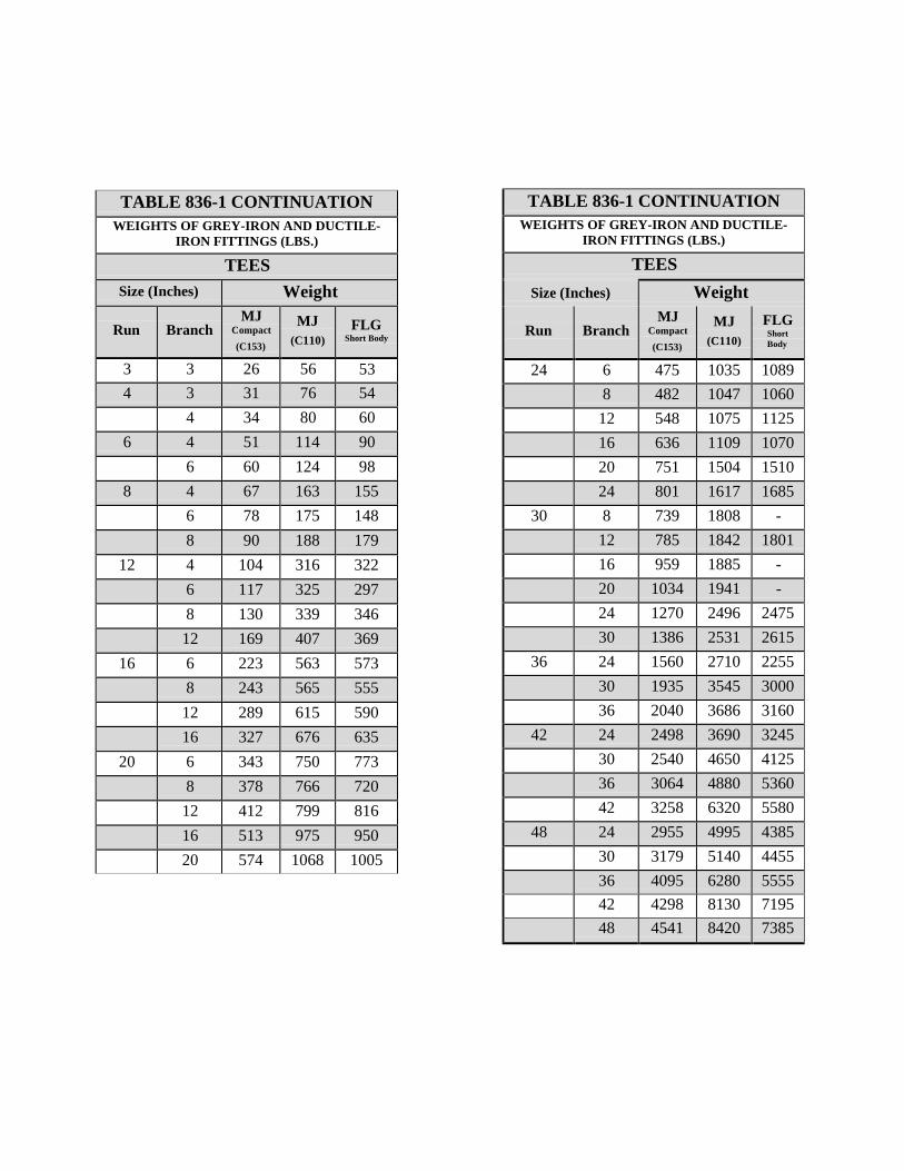
TABLE 836-1 CONTINUATION WEIGHTS OF GREY-IRON AND DUCTILE-
IRON FITTINGS (LBS.)
TEES Size (Inches) Weight
Run
Branch
MJ Compact (C153)
MJ (C110)
FLG Short Body
24 6 475 1035 1089 8 482 1047 1060 12 548 1075 1125 16 636 1109 1070 20 751 1504 1510 24 801 1617 1685
30 8 739 1808 - 12 785 1842 1801 16 959 1885 - 20 1034 1941 - 24 1270 2496 2475 30 1386 2531 2615
36 24 1560 2710 2255 30 1935 3545 3000 36 2040 3686 3160
42 24 2498 3690 3245 30 2540 4650 4125 36 3064 4880 5360 42 3258 6320 5580
48 24 2955 4995 4385 30 3179 5140 4455 36 4095 6280 5555 42 4298 8130 7195 48 4541 8420 7385
TABLE 836-1 CONTINUATION WEIGHTS OF GREY-IRON AND DUCTILE-
IRON FITTINGS (LBS.)
TEES Size (Inches) Weight
Run
Branch
MJ Compact (C153)
MJ (C110)
FLG Short Body
3 3 26 56 53 4 3 31 76 54
4 34 80 60 6 4 51 114 90
6 60 124 98 8 4 67 163 155
6 78 175 148 8 90 188 179
12 4 104 316 322 6 117 325 297 8 130 339 346 12 169 407 369
16 6 223 563 573 8 243 565 555 12 289 615 590 16 327 676 635
20 6 343 750 773 8 378 766 720 12 412 799 816 16 513 975 950 20 574 1068 1005
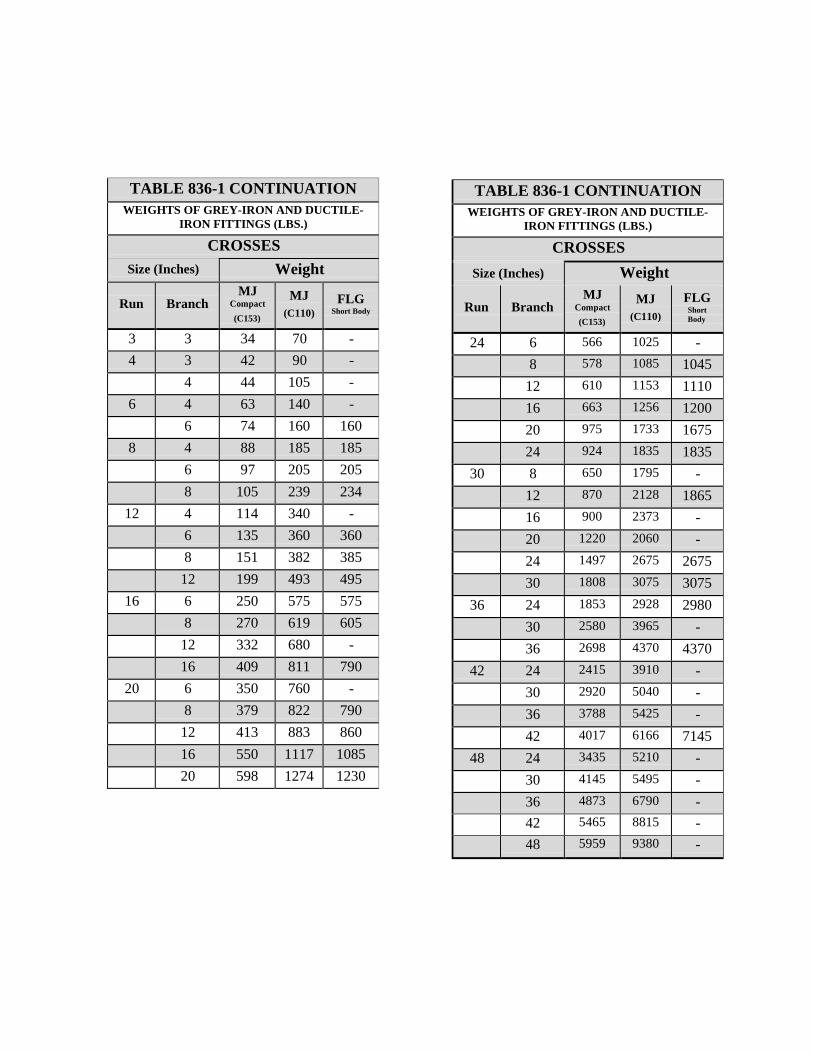
TABLE 836-1 CONTINUATION WEIGHTS OF GREY-IRON AND DUCTILE-
IRON FITTINGS (LBS.)
CROSSES Size (Inches) Weight
Run
Branch
MJ Compact (C153)
MJ (C110)
FLG Short Body
24 6 566 1025 - 8 578 1085 1045 12 610 1153 1110 16 663 1256 1200 20 975 1733 1675 24 924 1835 1835
30 8 650 1795 - 12 870 2128 1865 16 900 2373 - 20 1220 2060 - 24 1497 2675 2675 30 1808 3075 3075
36 24 1853 2928 2980 30 2580 3965 - 36 2698 4370 4370
42 24 2415 3910 - 30 2920 5040 - 36 3788 5425 - 42 4017 6166 7145
48 24 3435 5210 - 30 4145 5495 - 36 4873 6790 - 42 5465 8815 - 48 5959 9380 -
TABLE 836-1 CONTINUATION WEIGHTS OF GREY-IRON AND DUCTILE-
IRON FITTINGS (LBS.)
CROSSES Size (Inches) Weight
Run
Branch
MJ Compact (C153)
MJ (C110)
FLG Short Body
3 3 34 70 - 4 3 42 90 -
4 44 105 - 6 4 63 140 -
6 74 160 160 8 4 88 185 185
6 97 205 205 8 105 239 234
12 4 114 340 - 6 135 360 360 8 151 382 385 12 199 493 495
16 6 250 575 575 8 270 619 605 12 332 680 - 16 409 811 790
20 6 350 760 - 8 379 822 790 12 413 883 860 16 550 1117 1085 20 598 1274 1230
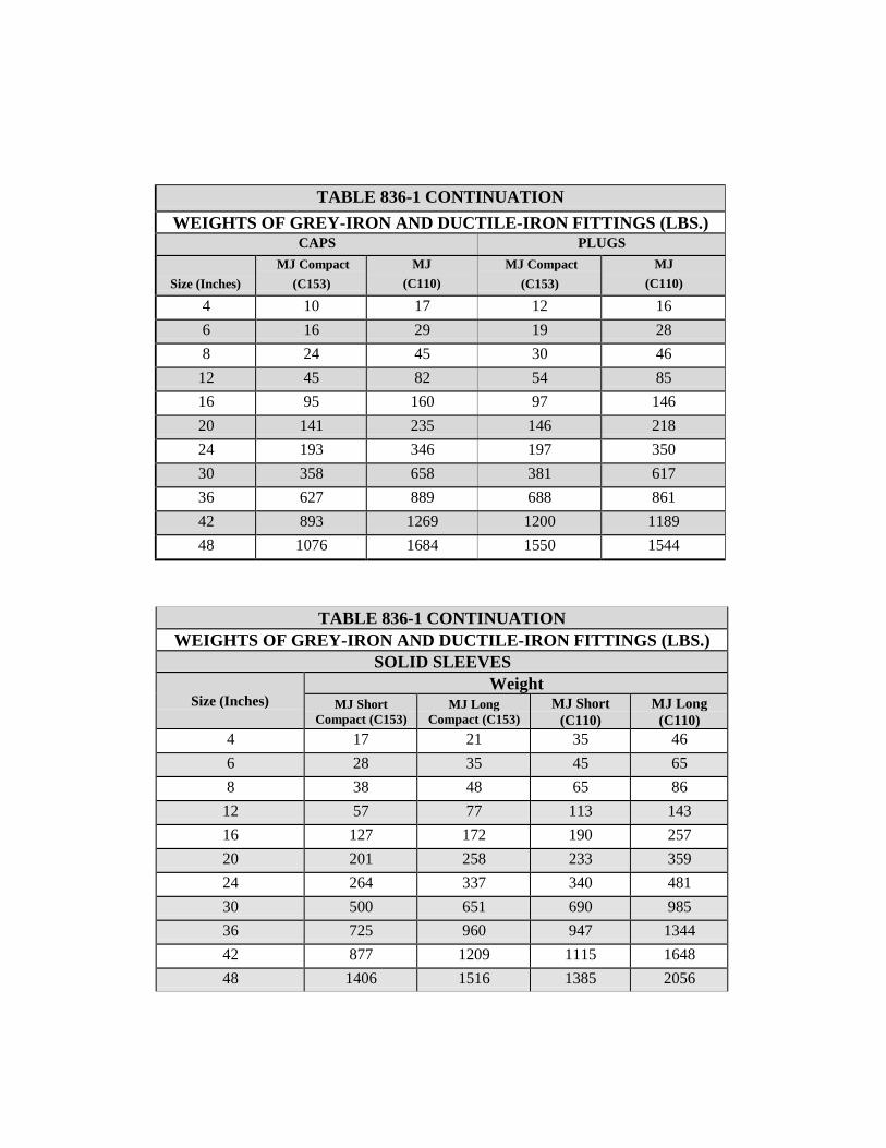
TABLE 836-1 CONTINUATION WEIGHTS OF GREY-IRON AND DUCTILE-IRON FITTINGS (LBS.)
CAPS PLUGS
Size (Inches)
MJ Compact (C153)
MJ (C110)
MJ Compact (C153)
MJ (C110)
4 10 17 12 16 6 16 29 19 28 8 24 45 30 46
12 45 82 54 85 16 95 160 97 146 20 141 235 146 218 24 193 346 197 350 30 358 658 381 617 36 627 889 688 861 42 893 1269 1200 1189 48 1076 1684 1550 1544
TABLE 836-1 CONTINUATION WEIGHTS OF GREY-IRON AND DUCTILE-IRON FITTINGS (LBS.)
SOLID SLEEVES
Size (Inches) Weight
MJ Short Compact (C153)
MJ Long Compact (C153)
MJ Short (C110)
MJ Long (C110)
4 17 21 35 46 6 28 35 45 65 8 38 48 65 86
12 57 77 113 143 16 127 172 190 257 20 201 258 233 359 24 264 337 340 481 30 500 651 690 985 36 725 960 947 1344 42 877 1209 1115 1648 48 1406 1516 1385 2056
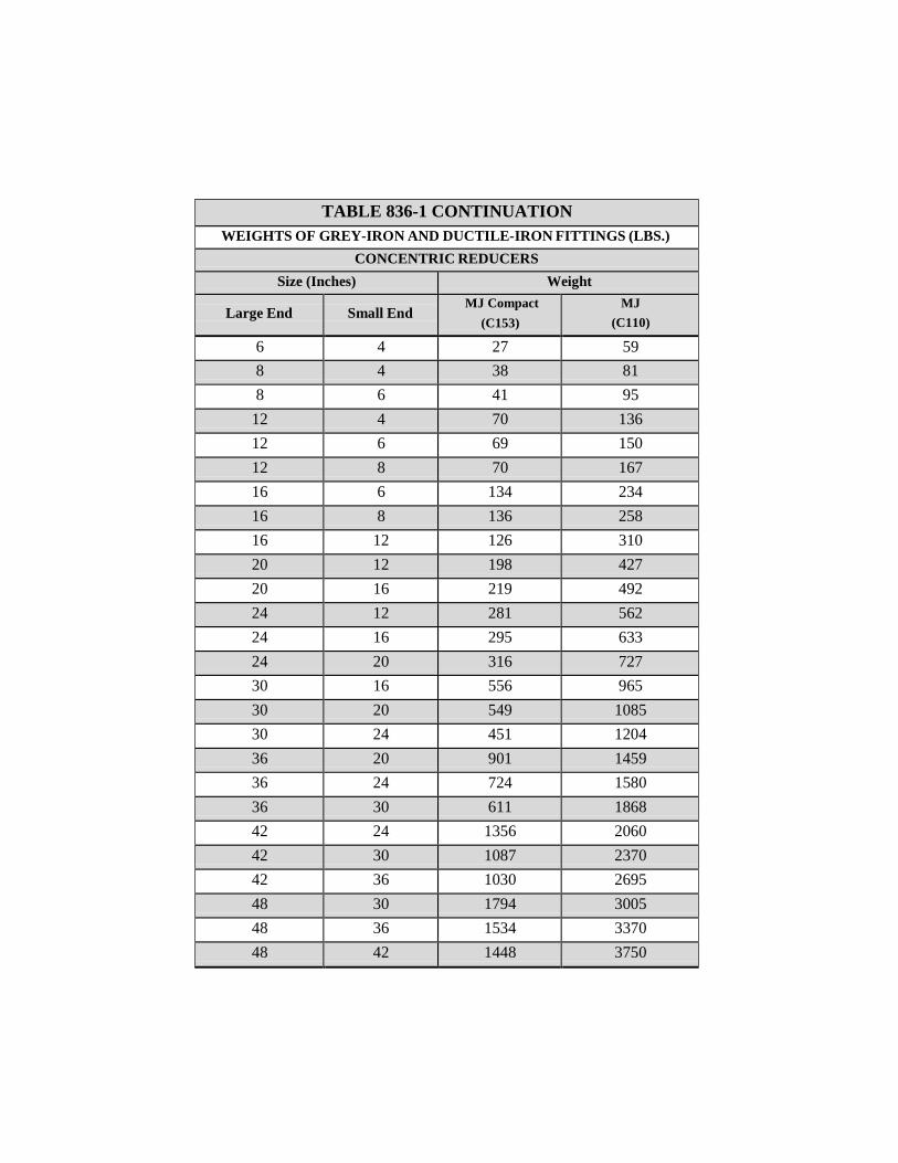
TABLE 836-1 CONTINUATION WEIGHTS OF GREY-IRON AND DUCTILE-IRON FITTINGS (LBS.)
CONCENTRIC REDUCERS Size (Inches) Weight
Large End
Small End MJ Compact
(C153) MJ
(C110)
6 4 27 59 8 4 38 81 8 6 41 95
12 4 70 136 12 6 69 150 12 8 70 167 16 6 134 234 16 8 136 258 16 12 126 310 20 12 198 427 20 16 219 492 24 12 281 562 24 16 295 633 24 20 316 727 30 16 556 965 30 20 549 1085 30 24 451 1204 36 20 901 1459 36 24 724 1580 36 30 611 1868 42 24 1356 2060 42 30 1087 2370 42 36 1030 2695 48 30 1794 3005 48 36 1534 3370 48 42 1448 3750
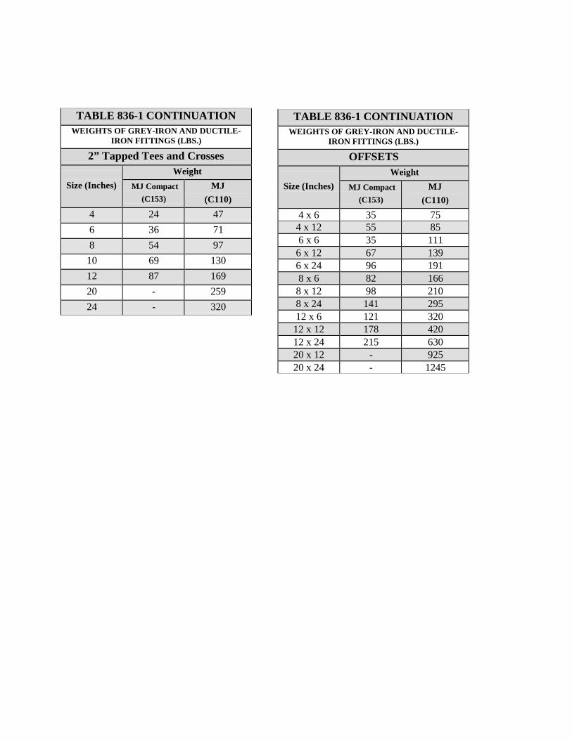
TABLE 836-1 CONTINUATION WEIGHTS OF GREY-IRON AND DUCTILE-
IRON FITTINGS (LBS.)
OFFSETS
Size (Inches)
Weight MJ Compact
(C153) MJ
(C110) 4 x 6 35 75 4 x 12 55 85 6 x 6 35 111 6 x 12 67 139 6 x 24 96 191 8 x 6 82 166 8 x 12 98 210 8 x 24 141 295 12 x 6 121 320
12 x 12 178 420 12 x 24 215 630 20 x 12 - 925 20 x 24 - 1245
TABLE 836-1 CONTINUATION WEIGHTS OF GREY-IRON AND DUCTILE-
IRON FITTINGS (LBS.)
2” Tapped Tees and Crosses
Size (Inches)
Weight MJ Compact
(C153) MJ
(C110) 4 24 47 6 36 71 8 54 97
10 69 130 12 87 169 20 - 259 24 - 320
ITEM NO. 839 ANCHORAGE AND THRUST BLOCKING
839.1 DESCRIPTION: This item shall consist of anchorage and thrust blocking
installation and adjustment, in accordance with these specifications and as directed by the Engineer.
839.2 MATERIALS: The materials for anchorage and thrust blocking installation
shall conform to the appropriate specifications contained within the latest revision of SAWS Material Specifications.
839.3 CONSTRUCTION: Suitable reaction blocking or anchorage shall be provided
at all of the following; dead ends, plugs, caps, tees, crosses, valves, and bends, in accordance with the Standard Drawings DD-839 Series when approved by SAWS Engineering in lieu of or in addition to joint restraints. All mechanical restraints shall be bidirectional. Anchor blocks shall be constructed solidly behind the fitting and symmetrical with the axis of resultant thrust, except where this is not possible as in the case of gravity anchorage for vertical bends. Special ties and anchor fittings may be utilized in conjunction with blocking when shown on the plans or as directed or authorized by the Engineer.
All thrust blocking shall be a minimum of 3000 psi concrete placed between solid ground and the fitting except as otherwise shown on the plans. The area of bearing in contact with solid ground shall be that shown on the plans or as directed by the Engineer.
All thrust blocking placed in conjunction with mains and appurtenances constructed in Pressure Zones (formally known as Service Levels) 9 through 15 shall be in accordance with Standard Drawings DD-839 Series. In all cases, the design of thrust blocking shall be of sufficient size to withstand a soil pressure of 3000 psf, unless specified otherwise in the job plans or specifications. The maximum soil pressure value that will be allowed for the design of thrust blocking shall be 5000 psf. When soil pressure bearing values of 4000 psf or 5000 psf are recorded for design of thrust blocks, copies of soil tests made for determining the bearing value of the soil in question shall be submitted to the Engineer for verification.
The blocking shall be placed so that pipe and fitting joints will be accessible. Pipe polywrap shall be placed between the pipe or fitting and the concrete.
The reaction block on the unused branch of a fitting shall be poured separately from the block across the back of the fitting. If they are poured simultaneously, a rigid partition shall be placed between the blocks.
Valves 12 inches or larger in size shall be supported on a concrete pad extending vertically from 12 inches below the bottom of the valve to the lower quarter point of the hub and laterally from face to face of hubs and transversely from wall to wall of the trench.
ITEM NO. 840 WATER TIE-INS
840.1 DESCRIPTION: This item shall consist of water main tie-ins installed in
accordance with these specifications and as directed by the Engineer. 840.2 MATERIALS: The materials for water main tie-ins shall conform to the
specifications contained within the latest revision of SAWS’ Material Specifications for all appropriate items.
840.3 CONSTRUCTION: The Contractor shall make tie-ins from new water mains to
existing water mains as shown on the plans or as directed by the Engineer. The Contractor shall be responsible for all shutdowns and isolation of the existing mains; cutting pipe for the connection; dewatering the excavation; customer notification of the shutdown; and all other requirements as directed by the Engineer or Inspector to provide completion in a safe and secure manner. All tie- ins shall be done after normal work hours. During construction, the planned shutdown and tie-in shall be coordinated through and approved by the Construction Inspector and accomplished at a time which will be at the least inconvenience to the customers. No additional compensation will be provided for tie-ins accomplished after normal working hours.
ITEM NO. 841 HYDROSTATIC TESTING OPERATIONS
841.1 DESCRIPTION: This item shall consist of hydrostatic testing
operations, of water mains in accordance with these specifications. 841.2 MATERIALS: The materials for hydrostatic testing operations
installation and adjustment shall conform to the appropriate specifications contained within the latest revision of SAWS’ Material Specifications.
841.3 CONSTRUCTION:
1. Flushing: Immediately upon completion of pipe laying, the
Contractor shall flush all mains laid. This flushing shall consist of completely filling sections of main between valves and then displacing such initial volumes of water by introducing clear water from existing facilities into and through the main to the point of discharge from the main being flushed. The flow-through shall continue until it is determined all dust, debris, or foreign matter that may have entered during pipe laying operations has been flushed out. The new line shall then be left under system pressure for testing.
To avoid damage to pavement and inconvenience to the public, fire hoses shall be used to direct flushing water from the main into suitable drainage channels or sewers
2. Operation of Valves: No valve in the Owner's water distribution
system shall be operated by the Contractor without prior permission of the Owner. The Contractor shall notify the Owner when a valve is to be operated and shall only operate the valve in the presence of the Owner's representative.
3. Hydrostatic Test: Except in the high pressure sections of the
water distribution system where test pressures will exceed 150 psi, all new mains shall be hydrostatically field tested at a maximum test pressure of 150 psi before acceptance by the Engineer/Owner. Where designated as "High Pressure Area," all new mains shall be hydrostatically field tested at a maximum test pressure of 200 psi before acceptance by the Engineer/Owner. It is the intent of these
Specifications that all joints be watertight and that all joints which are found to leak by observation during any test shall be made watertight by the Contractor. In case repairs are required, the hydrostatic field test shall be repeated until the pipe installation conforms to the specified requirements and is acceptable to the Engineer/Owner. The Contractor shall notify the Engineer/Owner prior to beginning the test and the Cibolo Construction Inspector may be present during the pressure test.
4. Test Procedures: After the new main has been laid and backfilled as
specified, but prior to chlorination and replacement of pavement, it shall be filled with water for a minimum of 24 hours and then subjected to a hydrostatic pressure test.
The specified test pressure shall be supplied by means of a pump connected to the main in a satisfactory manner. The pump, pipe connection, and all necessary apparatus including gauges and meters shall be furnished by the Contractor. Unless otherwise specified, the Owner will furnish water for filling lines and making tests through existing mains. Before applying the specified test pressure, all air shall be expelled from the main. To accomplish this, taps shall be made, if necessary, at the points of highest elevation and afterwards tightly plugged at no cost to the Owner. At intervals during the test, the entire route of the new main shall be inspected to locate any leaks or breaks. If any are found, they shall be stopped or repaired, and the test shall be repeated until satisfactory results are obtained. The hydrostatic test shall be made so that the maximum pressure at the lowest point does not exceed the specified test pressure.
The duration of each pressure test shall be a minimum of 4 hours for new mains in excess of 1000 linear feet and a minimum of 1 hour for new mains less than 1000 linear feet after the main has been brought up to test pressure. The test pressure shall be measured by means of a tested and properly calibrated pressure gauge acceptable to the Engineer/Owner. All pressure tests shall be continued until the Owner is satisfied that the new main meets the requirements of these Specifications.
Should any test of pipe in place disclose leakage greater than that listed in Table 841-1 or 841-2, "Hydrostatic Test Leakage Allowances," as applicable, the Contractor shall at his own expense locate and repair the defective joints until the leakage is within the specified allowance.
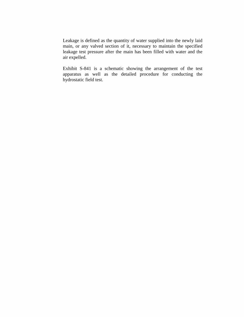
Leakage is defined as the quantity of water supplied into the newly laid main, or any valved section of it, necessary to maintain the specified leakage test pressure after the main has been filled with water and the air expelled.
Exhibit S-841 is a schematic showing the arrangement of the test apparatus as well as the detailed procedure for conducting the hydrostatic field test.
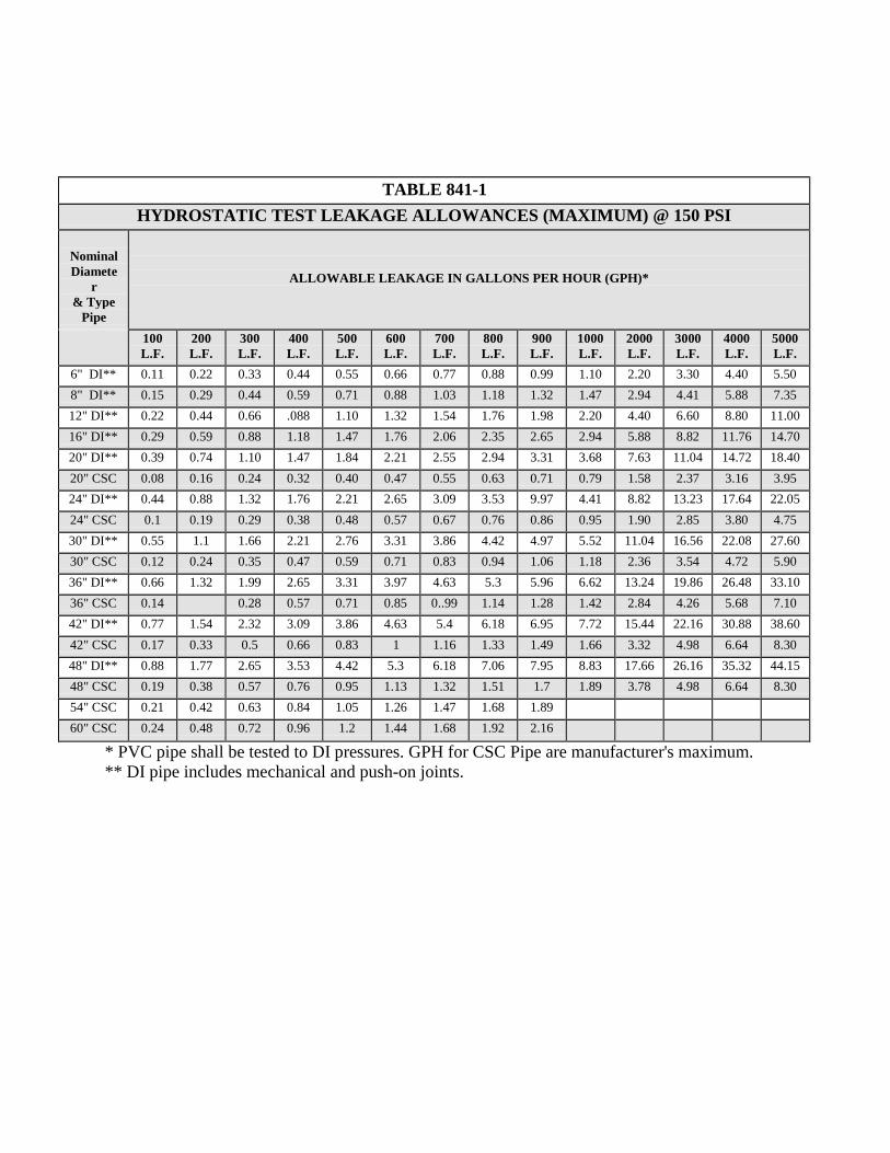
TABLE 841-1 HYDROSTATIC TEST LEAKAGE ALLOWANCES (MAXIMUM) @ 150 PSI
Nominal Diamete
r & Type
Pipe
ALLOWABLE LEAKAGE IN GALLONS PER HOUR (GPH)*
100 L.F.
200 L.F.
300 L.F.
400 L.F.
500 L.F.
600 L.F.
700 L.F.
800 L.F.
900 L.F.
1000 L.F.
2000 L.F.
3000 L.F.
4000 L.F.
5000 L.F.
6" DI** 0.11 0.22 0.33 0.44 0.55 0.66 0.77 0.88 0.99 1.10 2.20 3.30 4.40 5.50 8" DI** 0.15 0.29 0.44 0.59 0.71 0.88 1.03 1.18 1.32 1.47 2.94 4.41 5.88 7.35 12" DI** 0.22 0.44 0.66 .088 1.10 1.32 1.54 1.76 1.98 2.20 4.40 6.60 8.80 11.00 16" DI** 0.29 0.59 0.88 1.18 1.47 1.76 2.06 2.35 2.65 2.94 5.88 8.82 11.76 14.70 20" DI** 0.39 0.74 1.10 1.47 1.84 2.21 2.55 2.94 3.31 3.68 7.63 11.04 14.72 18.40 20" CSC 0.08 0.16 0.24 0.32 0.40 0.47 0.55 0.63 0.71 0.79 1.58 2.37 3.16 3.95 24" DI** 0.44 0.88 1.32 1.76 2.21 2.65 3.09 3.53 9.97 4.41 8.82 13.23 17.64 22.05 24" CSC 0.1 0.19 0.29 0.38 0.48 0.57 0.67 0.76 0.86 0.95 1.90 2.85 3.80 4.75 30" DI** 0.55 1.1 1.66 2.21 2.76 3.31 3.86 4.42 4.97 5.52 11.04 16.56 22.08 27.60 30" CSC 0.12 0.24 0.35 0.47 0.59 0.71 0.83 0.94 1.06 1.18 2.36 3.54 4.72 5.90 36" DI** 0.66 1.32 1.99 2.65 3.31 3.97 4.63 5.3 5.96 6.62 13.24 19.86 26.48 33.10 36" CSC 0.14 0.28 0.57 0.71 0.85 0..99 1.14 1.28 1.42 2.84 4.26 5.68 7.10 42" DI** 0.77 1.54 2.32 3.09 3.86 4.63 5.4 6.18 6.95 7.72 15.44 22.16 30.88 38.60 42" CSC 0.17 0.33 0.5 0.66 0.83 1 1.16 1.33 1.49 1.66 3.32 4.98 6.64 8.30 48" DI** 0.88 1.77 2.65 3.53 4.42 5.3 6.18 7.06 7.95 8.83 17.66 26.16 35.32 44.15 48" CSC 0.19 0.38 0.57 0.76 0.95 1.13 1.32 1.51 1.7 1.89 3.78 4.98 6.64 8.30 54" CSC 0.21 0.42 0.63 0.84 1.05 1.26 1.47 1.68 1.89 60" CSC 0.24 0.48 0.72 0.96 1.2 1.44 1.68 1.92 2.16
* PVC pipe shall be tested to DI pressures. GPH for CSC Pipe are manufacturer's maximum. ** DI pipe includes mechanical and push-on joints.
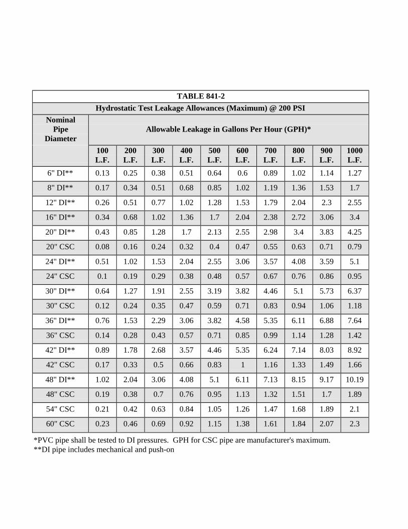
TABLE 841-2 Hydrostatic Test Leakage Allowances (Maximum) @ 200 PSI
Nominal Pipe
Diameter
Allowable Leakage in Gallons Per Hour (GPH)*
100 L.F.
200 L.F.
300 L.F.
400 L.F.
500 L.F.
600 L.F.
700 L.F.
800 L.F.
900 L.F.
1000 L.F.
6" DI** 0.13 0.25 0.38 0.51 0.64 0.6 0.89 1.02 1.14 1.27
8" DI** 0.17 0.34 0.51 0.68 0.85 1.02 1.19 1.36 1.53 1.7
12" DI** 0.26 0.51 0.77 1.02 1.28 1.53 1.79 2.04 2.3 2.55
16" DI** 0.34 0.68 1.02 1.36 1.7 2.04 2.38 2.72 3.06 3.4
20" DI** 0.43 0.85 1.28 1.7 2.13 2.55 2.98 3.4 3.83 4.25
20" CSC 0.08 0.16 0.24 0.32 0.4 0.47 0.55 0.63 0.71 0.79
24" DI** 0.51 1.02 1.53 2.04 2.55 3.06 3.57 4.08 3.59 5.1
24" CSC 0.1 0.19 0.29 0.38 0.48 0.57 0.67 0.76 0.86 0.95
30" DI** 0.64 1.27 1.91 2.55 3.19 3.82 4.46 5.1 5.73 6.37
30" CSC 0.12 0.24 0.35 0.47 0.59 0.71 0.83 0.94 1.06 1.18
36" DI** 0.76 1.53 2.29 3.06 3.82 4.58 5.35 6.11 6.88 7.64
36" CSC 0.14 0.28 0.43 0.57 0.71 0.85 0.99 1.14 1.28 1.42
42" DI** 0.89 1.78 2.68 3.57 4.46 5.35 6.24 7.14 8.03 8.92
42" CSC 0.17 0.33 0.5 0.66 0.83 1 1.16 1.33 1.49 1.66
48" DI** 1.02 2.04 3.06 4.08 5.1 6.11 7.13 8.15 9.17 10.19
48" CSC 0.19 0.38 0.7 0.76 0.95 1.13 1.32 1.51 1.7 1.89
54" CSC 0.21 0.42 0.63 0.84 1.05 1.26 1.47 1.68 1.89 2.1
60" CSC 0.23 0.46 0.69 0.92 1.15 1.38 1.61 1.84 2.07 2.3
*PVC pipe shall be tested to DI pressures. GPH for CSC pipe are manufacturer's maximum. **DI pipe includes mechanical and push-on
ITEM NO. 844 BLOW-OFF ASSEMBLIES
844.1 DESCRIPTION: This item shall consist of blow-off assemblies installed in
accordance with these specifications and as directed by the Engineer. 844.2 MATERIALS: The materials for blow-off assemblies, installation and
adjustment shall conform to the specifications contained within the latest revision of SAWS’ Material Specification.
844.3 CONSTRUCTION: Permanent and temporary blow-off assemblies shall be
installed where shown on the plans and/or at locations designated by the Engineer/Owner and at the end of all dead end mains in accordance with the Texas Administrative Code (TAC) rules to include TAC § 290.44 (5) (6) .
The permanent blow-off shall consist of the following; all galvanized iron pipe, valve, and fittings of the various sizes shown on the plans, 6 inch valve box assembly and concrete collar around the valve box. The temporary blow-off shall consist of the following; all galvanized iron pipe, valve and fittings of the various sizes shown on the plans. Valve box shall be raised or installed to finished grade and installed in accordance with Standard Drawing DD-844 Series.
ITEM NO. 845 FENCING DETAIL PROPERTY
MARKER DETAIL
Use the appropriate DD drawing number from Part H of this Design and Construction Manual
ITEM NO. 846
AIR RELEASE ASSEMBLIES 846.1 DESCRIPTION: This item shall consist of air release assemblies installed in
accordance with these specifications and as directed by the Engineer/Owner. 846.2 MATERIALS: The materials for air release assemblies installation and
adjustment shall conform to the specifications contained within the latest revision of SAWS’ Material Specification 29-01, "Air Release, Vacuum and Combination Air Valves."
846.3 CONSTRUCTION: Air release assemblies shall be installed at the location
shown on the plans or as directed by the Engineer.
Air release assemblies in an open trench water main installation shall be installed in accordance with Standard Drawing DD846 Series and shall include the valve, valve boxes, tapping saddle, pipe, fittings, accessories and appurtenances. It shall also include the service line and tap to the main line. Air release assemblies installed in parkways or easements and onside of street pavements shall be installed in accordance with Standard Drawing DD 846-01, sheet 2 of 2, regardless of size.
Air release assemblies installed on steel pipe attached to a bridge structure shall include the outlet on the steel pipe, the valve, valve box, pipe, fittings, security enclosure, accessories and appurtenances.
ITEM NO. 847
DISINFECTION 847.1 DESCRIPTION: This item shall consist of disinfection of new mains utilizing
Calcium Hypochlorite (HTH) in accordance with these specifications. Machine chlorination shall be performed by SAWS as specified in the specifications and drawings. The Contractor is required to provide all appurtenances to the pipe to allow machine chlorination.
847.2 MATERIALS: The materials for disinfection shall conform to the appropriate specifications contained within the latest revision of SAWS’ Material Specifications, Item No. 100-20.
847.3 CONSTRUCTION: After the new mains have successfully passed the pressure test specified in "Hydrostatic Testing Operations" Item No. 841, the Owner will disinfect only those mains shown on the plans or otherwise indicated as "Machine Chlorination by the City of Cibolo," and in accordance with the Standard Drawing DD-847. This disinfection shall include; chlorination, flushing, and placing the mains in service, as follows. All other disinfection requirements shall be accomplished by the Contractor. Disinfection by the Contractor is limited to sections of pipe less than 800 feet in length between sections.
1. Operation of Valves: During and after the disinfection of the mains, the Contractor shall be notified by the Engineer sufficiently in advance to enable the Contractor to have a competent representative present whenever valves are to be operated that will affect the pressure in any part of the work for which the Contractor is responsible.
2. Contractor's Personnel and Equipment: The Contractor shall supply labor and equipment necessary to make all excavations required for chlorination, equipment connections, subsequent flushing, and placing the mains in service.
3. Safeguarding and Backfilling Open Holes: The Contractor shall be responsible for safeguarding any open holes excavated or left open for flushing and disinfection purposes. Following completion of disinfection, the Contractor shall backfill holes in accordance with appropriate provisions of "Excavation, Trenching and Backfill", Item No. 804.
4. General: Mains shall be disinfected with dry HTH where shown on the
plans or as directed by the Engineer, and shall not exceed a total length of 800 feet. This method of disinfection will also be followed for main repairs. The Contractor shall utilize all appropriate safety measures to protect his personnel during disinfection operations.
5. Dosage: The Contractor shall disinfect the new or replaced mains with HTH of 70% available chlorine furnished by the Contractor. Sufficient HTH shall be used to obtain a minimum chlorine concentration of 50 ppm. Table 847-1, "Chlorine Dosage," is included for the convenience of the Contractor. A heaping tablespoon holds approximately ½ ounce, and a standard measuring cup holds approximately 8 ounces.
6. Filling the Main: Those sections of main to which the dry HTH has been applied shall be filled slowly to allow for the even distribution of the disinfecting material. The manipulation of valves shall be under the supervision of the Engineer's representative in accordance with "Operation of Valves", Item No. 847.3.1.
7. Holding Time: The length of time that sections of main disinfected with HTH shall be allowed to stand undisturbed will depend upon the particular job and Texas Commission on Environmental Quality (TCEQ) criteria.
a. When circumstances permit a shutdown with no customers out of service, the required minimum detention time will be 24 hours with a 50 ppm chlorine dosage.
b. When customers are out of service during a shutdown with no leakage past valves, the required minimum detention time will be 3 hours and the chlorine dosage will be 300 ppm.
c. When customers are out of service with some leakage past valves, the required minimum detention time will be 30 minutes with a 500 ppm chlorine dosage.
8. Flushing: Following the expiration of the specified holding time, the treated section of main shall be flushed thoroughly by the Contractor in accordance with the applicable provisions of "Hydrostatic Testing Operations", Item No. 841. Flushing shall continue until no chlorine remains detectable by taste or odor or until the chlorine residual is less than 0.3 ppm. The Contractor must make provisions for the disposal and runoff of the flushing operations in order to minimize erosion or impact to residents.
9. Preventing Reverse Flow: Valves shall be manipulated so that the strong
chlorine solution in the line being treated will be flushed out of the main and will not flow back into the line supplying the water.
10. Supervision. All disinfection of mains shall be done under the general supervision of a representative of the Owner.
11. Additional Treatment: Should the new main fail to meet minimum public
health standards for bacteriological quality after flushing, further treatment shall be as directed by the Engineer. If further disinfection is required, chlorination shall be done in accordance with the City of Cibolo guidelines for Disinfection of New Mains Utilizing Machine Chlorination. In no case, however, shall the new line be acceptable as complete and satisfactory until the bacteriological quality of the water taken from the main meets the standards of the TCEQ.
12. Safeguarding and Backfilling Open Holes: The requirements for
safeguarding and backfilling all holes excavated or left open for chlorinating and sampling shall be as specified in "Trench Excavation Safety Protection", of the City of Cibolo Specifications.
If an open hole is unsafe and does not have proper trench protection, City of Cibolo will not chlorinate project until acceptable trench protection is provided.
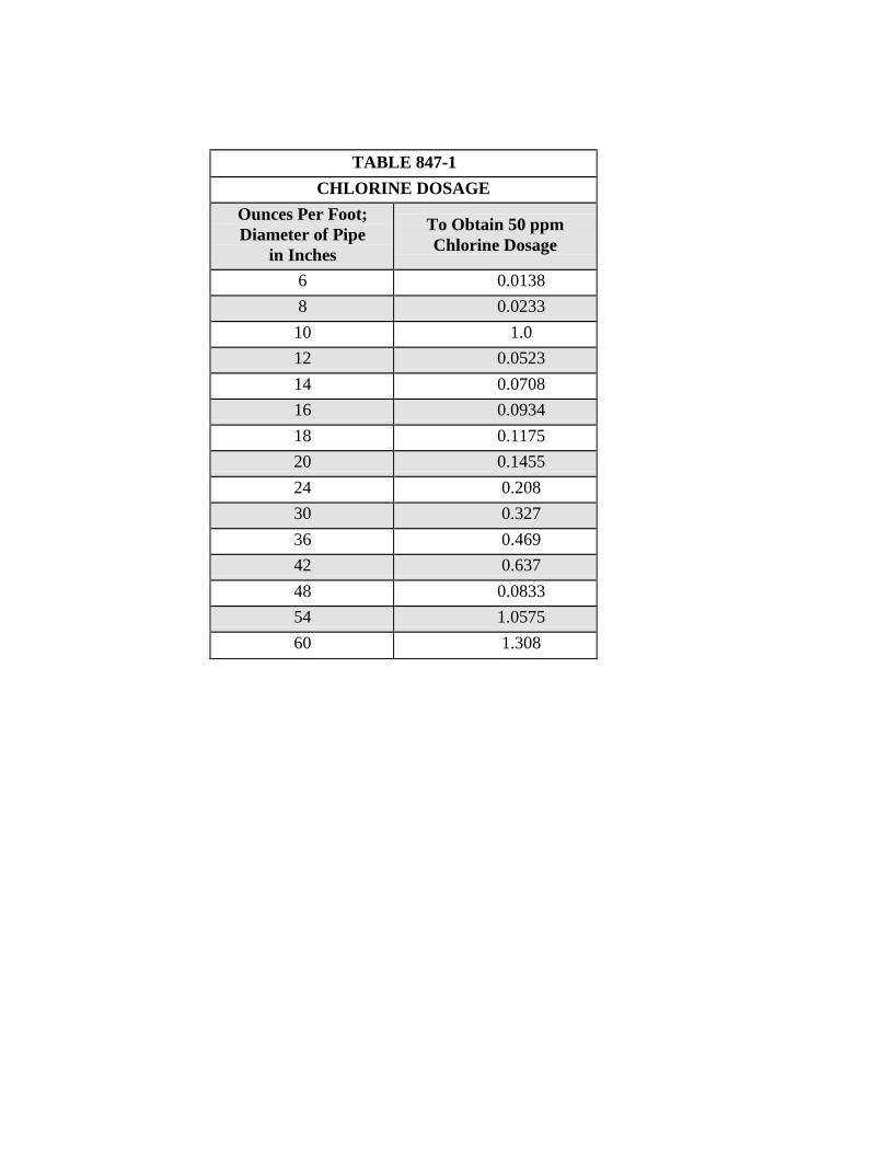
TABLE 847-1
CHLORINE DOSAGE Ounces Per Foot; Diameter of Pipe
in Inches
To Obtain 50 ppm Chlorine Dosage
6 0.0138 8 0.0233 10 1.0 12 0.0523 14 0.0708 16 0.0934 18 0.1175 20 0.1455 24 0.208 30 0.327 36 0.469 42 0.637 48 0.0833 54 1.0575 60 1.308
ITEM NO. 848 SANITARY SEWERS
848.1 DESCRIPTION: This item shall govern the furnishing, installation and jointing of sanitary sewer pipe of the size and type specified by the project's plans and specifications.
All plans, materials and specifications shall be in accordance with the Texas Administrative Code (TAC) rules to include: 30 TAC § 213, and Design Criteria for Sewerage Systems 30 TAC § 217, or any revisions thereto as applicable.
848.2 MATERIALS: Materials for sanitary sewer pipe and fittings shall be either rigid or flexible. All pipe not listed shall be subject to approval by the SAWS Material Standards and/or the City Engineer.
1. Rigid Pipe: Reinforced concrete, ductile iron, cast iron and concrete steel cylinder pipe shall for the purpose of this specification be known as rigid pipe.
2. Flexible Pipe: Pipe consisting of materials other than those listed above.
a. Any flexible conduit having a deflection of the inside diameter greater than 5% after installation will not be accepted.
A "GO, NO-GO" Deflection Testing Mandrel built in accordance with the detail drawing, as shown on the Drawings DD-848, and 30 TAC § 217, shall be furnished at the Contractor's expense and shall be used in testing pipe deflection for acceptance, unless directed otherwise by the Engineer. Refer to Specification Item No. 849 for more information about Mandrel Deflection testing.
b. Working room: The working room for flexible pipe shall be a minimum of 6 inches.
c. Pipe Stiffness:
All mains are to be SDR 26 PVC (ASTM D-3034) with a minimum stiffness of 115 PSI.
d. At waterline crossings and where water and sewer mains are parallel and separation distance cannot be achieved as per 30 TAC § 217.13, use pressure rated pipe SDR 26 PVC (ASTM D-2241) with a minimum pressure rating of 150 PSI.
3. Concrete Pipe:
a. Concrete pipe and fittings less than 18" in diameter shall conform to ASTM Designation C-14.
b. Concrete pipe and fittings 18" and larger in diameter shall conform to ASTM Designation C-76, Class III, or C-655.
c. When the depth of cover over the top of the pipe is over 14 feet, concrete pipe less than 18" in diameter shall be extra strength and shall conform to ASTM Designation C-14, Class III, as a minimum.
d. When the depth of cover over the top of the pipe is over 14 feet, concrete pipe 18" and larger in diameter shall conform to ASTM Designation C-76, Class IV, or C-655, as a minimum.
e. All joints and joint material for concrete pipe and fittings shall conform to ASTM Designation C-443.
4. Asbestos-Cement (AC) Pipe: AC pipe shall not be used.
5. Fiberglass Reinforced Sewer Pipe, Non-Pressure Type: Fiberglass reinforced sewer pipe, non-pressure type, shall be a factory-formed conduit of polyester resin, continuous roving glass fibers and silica sand built up in laminates and shall conform to the requirements of ASTM D- 3262 including the appendix and subsequent specifications, and in accordance with the SAWS material specifications.
Coupling Joints: Joints for pipe and fittings shall be confined compression rubber gasket bell and spigot type joints conforming to the material and performance requirements of ASTM D-4161.
Fittings: Flanges, elbows, reducers, tees, wyes, laterals, and other fittings shall be capable of withstanding all operating conditions when installed. They may be contact molded or manufactured from mitered sections of pipe joined by glass-fiber reinforced overlays. For pipes 15" or larger in diameter, lateral openings 6 inch or greater in size shall be made using PVC sewer saddles conforming to ASTM D-2661 or insert a Tee connections conforming to ASTM D-3034 or approved equal.
Minimum pipe stiffness shall not be less than 115 psi for direct bury applications.
6. PSM Polyvinylchloride (PVC) Sewer Pipe: Pipe shall be made from class 12454-B materials as prescribed in ASTM-D 1784. For pipes 4" to 15" in diameter, PSM pipe, fittings and joints shall conform to ASTM D-3034 and D-3212, with the exception that solvent cement joints shall not be used. All pipes that are 18" to 27" in diameter shall meet the requirements of ASTM F-679.
7. Modified Grade 5 Gravel Bedding/Backfilling: The bedding material for concrete steel cylinder pipe (CSC), ductile iron pipe (DI), H.D.P.E. pipe, wrapped steel pipe and polyvinyl chloride pipe (PVC) in all nominal diameters shall be
composed of well–graded, crushed stone or gravel, conforming to the following requirements, unless modified by the Design Engineer and approved by the City Engineer: MODIFIED GRADE 5 PERCENT Retained on ½” sieve 0 Retained on 3/8” sieve 0-5 Retained on No. 4 sieve 20-80 Retained on No. 10 sieve 75-100 Retained on No. 20 sieve 98-100
8. Pressure Pipe/Force Mains: Pipe shall be made from Class 1254-A or 1254-B, as defined in ASTM D-1784. All pipe, fittings, and joints shall meet or exceed the requirements of ASTM Designation 2241, with the exception that solvent cement joints shall not be used. The pressure rating, size, and pressure class shall be as shown on the plans. Pipe shall have an integral bell and gasket seal with the locked-in type gasket reinforced with a steel band or other rigid material conforming to ASTM F-477. The joint shall comply with the requirements of ASTM D-3139. Pressure pipe/Force mains are required to have modified grade 5 material used as bedding. Pipes also shall be hydrostatically tested at minimum of 100 psi after their construction to ensure proper construction.
9. Mechanical or compression joints, concrete jointing collars, or non- reinforced rubber adaptors shall be used only as approved by the Owner.
10. Ductile Iron Pipe and Fittings: Ductile iron pipe shall be centrifugally cast of 60-42-10 iron and shall conform to the requirements of the latest revision of ANSI Standard A21.51/American Water Works Association (AWWA) C151. Thickness or class shall be that required for laying condition type 4 or 5, in accordance with actual conditions at the site. Ductile iron pipe may be "thickness designed" in accordance with requirements of the latest revision of ANSI Standard A21.50/AWWA C150. Thickness design shall be based on standard laying conditions 4 or 5 in accordance with conditions at the site. Fittings for ductile iron pipe shall have not less than the thickness, class, or pressure rating specified for ductile iron pipe. Fittings shall be furnished with all necessary glands, gaskets, bolts, etc. as may be required to complete the joints.
Rubber gasket joints for mechanical joints or push on type joints shall conform to the requirements of ANSI Standard A21/AWWA C111. All ductile iron pipe and fittings shall be cement mortar lined or polyethylene lined. The cement mortar lining shall be in accordance with ANSI A21.4/AWWA C104.
The polyethylene lining material for pipe and fitting shall be virgin polyethylene complying with ANSI/ASTM D-1248, compounded with inert filler and with
sufficient carbon black to resist ultraviolet rays during storage of the pipe and fittings. The polyethylene shall be bonded to the interior of the pipe or fitting by heat. Polyethylene lining in pipe and in fittings shall be 40 mils nominal thickness. Minimum lining thickness shall be 30 mils.
11. Concrete Steel Cylinder Pipe: Prestressed concrete pipe and fittings shall
conform to AWWA Specification C-301, as outlined in SAWS Material Specification Item No. 05-20, or AWWA Specification C-303, as outlined in SAWS Material Specification Item No. 05-40.
12. All sanitary sewer pipe and fittings produced within the jurisdiction of the City of Cibolo shall be accompanied by a certificate of compliance to these specifications prepared by an independent testing laboratory and signed by a registered professional engineer.
848.3 CONSTRUCTION: All sanitary sewer mains shall be constructed in accordance with the specifications herein outlined and in conformity with the required lines, grades, and details shown on the plans and as directed by the Engineer. Successful passage of the air test, as described under TCEQ
Criteria, shall be required for the acceptance of the mains.
1. Water Main Crossings: Where gravity or force main sewers are constructed in the vicinity of water mains, the requirements of the 30 TAC § 217.5 shall be met.
2. For excavation, trenching and backfill requirements see Item No. 804.
3. Pipe Laying: The Owner will inspect all pipe before it is placed in the trench and will reject any sections found to be damaged or defective to a degree that would affect the friction of the pipe. Rejected pipe shall be immediately removed from the site of the work. The Contractor shall be required to commence construction and laying of pipe at the downstream end of the sanitary sewer outfall line and proceed non-stop in a forward upstream direction. No pipe shall be laid within 10 feet of any point where excavation is in progress. Pipe laying shall proceed upgrade with the tongue or spigot pointing in the direction of flow. Pipe shall be lowered into the trench without disturbing the prepared foundation or the trench sides. The drilling of lifting holes in the field will not be permitted. Pipe shall be installed by means of a concentric pressure being applied to the pipe with a mechanical pipe puller. Pulling or pushing a joint of pipe in place by using a crane, bulldozer, or backhoe will not be permitted. Pipe shall be pulled home in a straight line with all parts of the pipe on line and grade at all times. No side movement or up and down movement of the pipe will be permitted during or after the pulling operation. Should coupled pipe joints be out of line or off grade, they shall be removed one joint at a time and brought to the
proper line and grade. The lifting or moving of several joints of coupled pipe at one time to close a partially open joint or to fine grade under laid joints of pipe will not be permitted.
4. Laser Beams: The use of laser beams for vertical control shall be required provided the Contractor makes available to the Inspector, when requested, a level and rod of sufficient sensitivity to accurately determine differences in elevation between points 300 feet apart with one instrument set-up. No pipe shall be installed in tunnels except as provided on the plans, or with the permission of the Engineer. If the Contractor finds it necessary to install pipe in tunnels not provided on the plans, he shall submit to the Engineer, prior to commencement of w ork, a detailed outline of procedures, methods, and use of materials depending on existing soil conditions.
No horizontal or vertical curves shall be permitted in conformance with appropriate regulatory agency requirements.
Before leaving the work unattended, the upper ends of all pipelines shall be securely closed with a tight fitting plug or closure. The interior of laid pipe shall be kept free from dirt, silt, gravel, or foreign material at all times. All pipes in place must be approved before backfilling. When replacing an existing system in place, Contractor shall maintain screens to prevent the entrance of construction debris into the sewer system.
ITEM NO. 849 AIR AND DEFLECTION TESTING (SANITARY SEWER)
849.1 DESCRIPTION: This item shall consist of air and deflection test in accordance
with this specification. 849.2 MATERIALS: The materials for air and deflection test shall conform to the
appropriate specifications contained within the latest revision of SAWS Material Specifications.
849.3 TESTING OF INSTALLED PIPE: An infiltration, ex-filtration or low-pressure air
test shall be specified. Copies of all test results shall be made available to the Inspector upon request. Tests shall conform to the following requirements:
1. Low Pressure Air Test: The procedure for the low pressure air test shall
conform to the procedures described in ASTM C-828, ASTM C-924, ASTM F-1417 or other appropriate procedures, except for testing times. The test times shall be as outlined in this section. For sections of pipe less than 36-inch average inside diameter, the following procedure shall apply unless the pipe is to be joint tested. The pipe shall be pressurized to 3.5 psi greater than the pressure exerted by groundwater above the pipe. Once the pressure is stabilized, the minimum time allowable for the pressure to drop from 3.5 pounds per square inch gauge to 2.5 pounds per square inch gauge shall be computed from the following equation:
0.085 x D x K
T = Q
T = Time for pressure to drop 1.0 pound per square inch gauge in seconds
K = 0.000419xDxL, but not less than 1.0
D = Average inside pipe diameter in inches
L = Length of line of same pipe size being tested, in feet
Q = Rate of loss, 0.0015 cubic feet per minute per square foot internal
surface shall be used since a K value of less than 1.0 shall not be used.
There are minimum testing times for each pipe diameter as follows:
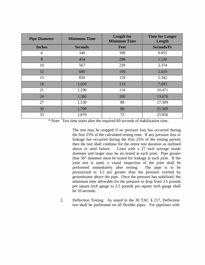
Pipe Diameter
Minimum Time Length for Minimum Time
Time for Longer Length
Inches Seconds Feet Seconds/Ft 6 340 398 0.855 8 454 298 1.520 10 567 239 2.374 12 680 199 3.419 15 850 159 5.342 18 1,020 133 7.693 21 1,190 114 10.471 24 1,360 100 13.676 27 1,530 88 17.309 30 1,700 80 21.369 33 1,870 72 25.856
* Note: Test time starts after the required 60 seconds of stabilization time.
The test may be stopped if no pressure loss has occurred during the first 25% of the calculated testing time. If any pressure loss or leakage has occurred during the first 25% of the testing period, then the test shall continue for the entire test duration as outlined above or until failure. Lines with a 27 inch average inside diameter and larger may be air tested at each joint. Pipe greater than 36” diameter must be tested for leakage at each joint. If the joint test is used, a visual inspection of the joint shall be performed immediately after testing. The pipe is to be pressurized to 3.5 psi greater than the pressure exerted by groundwater above the pipe. Once the pressure has stabilized, the minimum time allowable for the pressure to drop from 3.5 pounds per square inch gauge to 2.5 pounds per square inch gauge shall be 10 seconds.
2. Deflection Testing: As stated in the 30 TAC § 217, Deflection
test shall be performed on all flexible pipes. For pipelines with
inside diameters less than 27”, a rigid mandrel shall be used to measure deflection. For pipelines with an inside diameter 27” and greater, a method approved by the Engineer or Inspector shall be used to test for vertical deflections. Other methods shall provide a precision of + 0.2% deflection. The test shall be conducted after the final backfill has been in place at least 30 days. No pipe shall exceed a deflection of five percent. If a pipe should fail to pass the deflection test, the problem shall be corrected and a second test shall be conducted after the final backfill has been in place an additional 30 days. The tests shall be performed without mechanical pulling devices. The design engineer should recognize that this is a maximum deflection criterion for all pipes and a deflection test less than 5 % may be more appropriate for specific types and sizes of pipe. Upon completion of construction, the design engineer or other Texas Registered Professional Engineer appointed by the owner shall certify, to the Construction Manager, that the entire installation has passed the deflection test. This certification may be made in conjunction with the notice of completion required in 30 TAC § 217.1 (1) of this title (relating to General Provisions). This certification shall be provided for the Commission to consider the requirements of the approval to have been met.
a. Mandrel Sizing. The rigid mandrel shall have an outside
diameter (O.D.) equal to 95% of the inside diameter (I.D.) of the pipe. The inside diameter of the pipe, for the purpose of determining the outside diameter of the mandrel, shall be the average outside diameter minus two minimum wall thicknesses for O.D. controlled pipe and the average inside diameter for I.D. controlled pipe, all dimensions shall be per appropriate standard. Statistical or other "tolerance packages" shall not be considered in mandrel sizing.
b. Mandrel Design: The rigid mandrel shall be constructed of
a metal or a rigid plastic material that can withstand 200 psi without being deformed. The mandrel shall have nine or more "runners" or "legs" as long as the total number of legs is an odd number. The barrel section of the mandrel shall have a length of at least 75% of the inside diameter of the pipe. A proving ring shall be provided and used for each size mandrel in use.
c. Method Options: Adjustable or flexible mandrels are prohibited. A television inspection is not a substitute for the deflection test. A deflectometer may be approved for use on a case by case basis. Mandrels with removable legs or runners may be accepted on a case by case basis.
ITEM NO. 850 SANITARY SEWER STRUCTURES
850.1 DESCRIPTION: This item shall govern for the construction of all concrete
sanitary sewer structures other than standard sanitary sewer manholes (Item No. 852). All plans, materials and specifications shall be in accordance with the Texas Administrative Code (TAC) rules to include: Design Criteria for Sewerage Systems 30 TAC § 217, or any revisions thereto as applicable. All structures shall be watertight and coated with a SAWS approved sewer structural coating.
850.2 MATERIALS:
1. Concrete: All concrete shall conform to the provisions of "Concrete (Class A)", Item No. 300, of these specifications or shall be of the class as noted on the plans.
2 Reinforcing Steel: All reinforcing steel shall conform to the provisions of
"Reinforcing Steel", Item No. 301 of these specifications.
3. Membrane Curing Compound: All membrane curing compound shall conform to the provisions of "Membrane Curing”, Item No. 305, of these specifications.
4. Manhole Rings and Covers: All manhole rings and covers shall conform
to the provisions of "Sanitary Sewer Manholes", Item No. 852, or as designated by the plans and specifications. If concrete throat rings are to be installed they must be used in conjunction with a UV stabilized polyethylene liner and I/I barrier. I/I barrier must meet the following ASTM standards: ASTM D-790/1505 Density of Polyethylene Materials, ASTM D1238 Melt Flow index, ASTM 638 Tensile Strength @ Yield (50mm/mm), ASTM 790 Flexural Modulus, ASTM 648 Heat Deflection temperature @ IGEPAL, ASTM 1693 EsCR, 100% IGEPAL/10% IGEPAL.
5. Coating: All structures and non-structures shall be watertight and the
interior walls coated with a SAWS approved sewer structural coating. For existing and rehabilitated structures, apply a combination of both products with the cementitious coating first, followed by the epoxy coating. Lafarge SewperCoat 2000 HR regular, with the required one inch thick application, is the only product yet approved which satisfies the requirement of applying the combination of both the cementitious coating and epoxy coating. Approved materials are as follows:
Cementitious coating: With required one inch thick application. • Permacast CR-5000 • Strong - Seal MS-2C • Standard Cement Material Inc. Reliner • Quadex Aluminaliner
Epoxy coating: With specified thickness application.
• Raven 405 Series High Build Epoxy Liner: Required thickness 125 mils
• Spray Wall polyurethane System: Required thickness 150 mils
850.3 CONSTRUCTION: All concrete sanitary sewer structures shall be constructed
in accordance with the specifications herein outlined and in conformity with the required lines, grades, sections, and details shown on the plans or as directed by the Engineer.
Construction methods shall conform to all applicable terms of "Concrete Structures”, Item No. 307, of these Specifications. Where portions of structures are shown on the plan details to be paid per Item No. 404C, such portions shall be constructed in accordance with applicable provisions of "Sanitary Sewer Manholes", Item No. 852. Sanitary sewer structures constructed to function as manholes or maintenance access appurtenances to gravity sewer systems shall be constructed to accommodate influent and effluent pipes greater than 24” in diameter as shown in Standard Drawing DD-850-01.
850.4 TESTING:
1. Hydrostatic Testing: Hydrostatic testing shall be conducted by plugging
with approved plugs all influent and effluent pipes in the structure and filling the structure to the top of the structure cone with water. Additional water may be added over a 24 hour period to compensate for absorption and evaporation losses. At the conclusion of the 24 hour saturation period the structure shall be filled to the top of the manhole cone and observed. A loss within a 30 min. period shall be considered an unsuccessful test.
2. Vacuum Testing:
a. General: Structures shall be tested after installation and prior to backfilling with all connections (existing and/or proposed) in place. Lift holes shall be plugged with an approved non-shrink grout prior to testing. Drop-connections and gas sealing connections shall be installed prior to testing.
b. Test Procedure: The lines entering the manhole shall be
temporarily plugged with the plugs braced to prevent them from being drawn into the manhole. The plugs shall be installed in the lines beyond drop connections, gas sealing connections, etc. The test head shall be inflated in accordance with the manufacturer's recommendations. A vacuum of 10 inches of mercury shall be drawn, and the vacuum pump will be turned off. With the valve closed, the level vacuum shall be read after the required test time. If the drop in the level is less than 1 inch of mercury (final vacuum greater than 9 inches of mercury), the manhole will have passed the vacuum test. The required test time is determined from Table 852-1.
c. Acceptance: Manholes will be accepted with relation to vacuum test
requirements if they meet the criteria above. Any manhole which fails the initial test must be repaired with a non-shrink grout or other suitable material based on the material of which the manhole is constructed. Manholes shall be repaired on the exterior surface only prior to backfilling. The manhole shall be retested as described above until a successful test is made. After a successful test, the temporary plugs will be removed.
d. Repairs to existing manholes: Any existing manhole which fails to
pass the vacuum test shall be closely examined by the Owner and the Contractor to determine if the manhole can be repaired. Thereafter, the Contractor shall either repair or remove and replace the manhole as directed. The manhole shall then be retested and coated with an approved sewer structural coating as stated above. The Owner may elect to simply remove and replace the existing manhole with a new manhole. Any manhole excavated for repairs or excavated for tie in shall be backfilled with flowable fill up to 1 foot below the cone.
ITEM NO. 851 ADJUSTING EXISTING MANHOLES
851.1 DESCRIPTION: This item shall consist of the adjustment of all existing
manholes, to include the replacing of existing manhole covers and rings regardless of type shown on the plans and in conformity with the provisions of these specifications. All manholes shall be watertight and coated with a SAWS approved sewer structural coating.
851.2 CONSTRUCTION: Manholes shall be lowered below street subgrade before
placing base materials, and openings shall be protected by hatch covers.
Existing manhole rings and covers which are determined by the Cibolo Inspector to be in an unacceptable condition, will be removed and replaced with new rings and covers. If cone section is removed the contractor is to upgrade to a 30” opening as required by 30 TAC 217. Contractor shall take all necessary measures to prevent damage to existing or new rings, cover, or cone from equipment and materials used in or taken through the work area. If an existing or new manhole cover, ring, or cone is damaged by the Contractor, it shall be replaced (as directed by SAWS inspector) by the Contractor at his expense. If concrete throat rings are to be installed they must be used in conjunction with a UV stabilized polyethylene liner and I/I barrier. I/I barrier must meet the following ASTM standards: ASTM D-790/1505 Density of Polyethylene Materials, ASTM D1238 Melt Flow index, ASTM 638 Tensile Strength @ Yield (50mm/mm), ASTM 790 Flexural Modulus, ASTM 648 Heat Deflection temperature @ IGEPAL, ASTM 1693 EsCR, 100% IGEPAL/10% IGEPAL.
Manholes shall be adjusted after street the base material has been laid and before placing of the surface course. Manholes that are going to be adjusted on an existing surface course not being replaced will be in accordance to the City of San Antonio Utility Excavation Criteria Manual Standard Drawing No. 8.8. All manholes shall then be raised, or lowered a sufficient height so as to be level with the finished surface course. Adjustment in height will be made by addition or removal of “throat rings” above the manhole “cone” where feasible. A minimum of two and a maximum of six throat rings may be used at each adjusted manhole. Note: All new manhole installation shall not exceed four throat rings.
All manholes shall be watertight and the interior walls coated with a SAWS approved sewer structural coating.
For adjusted manholes, apply a combination of both products with the cementitious coating first, followed by the epoxy coating. Lafarge SewperCoat 2000 HR regular, with the required one inch thick application, is the only product
yet approved which satisfies the requirement of applying the combination of both the cementitious coating and epoxy coating. Approved materials are as follows:
Cementitious coating: With required one inch thick application.
• Permacast CR-5000 • Strong - Seal MS-2C • Standard Cement Material Inc. Reliner • Quadex Aluminaliner
Epoxy coating: With specified thickness application.
• Raven 405 Series High Build Epoxy Liner: Required thickness 125 mils
• Spray Wall polyurethane System: Required thickness 150 mils
Material excavation from around the manholes shall be replaced with flowable concrete in accordance with Standard Drawings, and select materials from the excavation (as shown on the plans or specified by the City of Cibolo). All excess materials shall be disposed of by the Contractor in an approved location.
ITEM NO. 852 SANITARY SEWER MANHOLES
852.1 DESCRIPTION: This item shall govern the construction of standard sanitary
sewer manholes complete in place and the materials therein, including manhole rings and covers. All plans, materials and specifications shall be in accordance with the Texas Administrative Code (TAC) rules to include: Design Criteria for Sewage Systems 30 TAC § 217 or any revisions thereto. M anholes shall be watertight & coated with a SAWS approved sewer structural coating.
1. Types: Unless otherwise shown on the plans and details or approved by
the Engineer, standard sanitary sewer manholes shall be constructed on influent or effluent pipes less than 24" in diameter with precast reinforced concrete manhole sections or be monolithically poured concrete manholes. A standard sanitary sewer manhole shall be a single maintenance entrance cylindrical structure having a uniform internal diameter of 4, 5 or 6 feet structure to the bottom of the diameter adjustment section or cone. The base of the structure shall include the load bearing portion beneath and exterior of the structure, invert channels and the fill or bench portions adjacent to the lower sewer pipes within the structure. The maximum vertical height of the diameter adjustment section or cone shall be 36 inches. Adjustment or throat rings may be used for elevation adjustment of the manhole ring and cover. Manhole ring concrete encasement as shown on the plan details shall be provided to attach the ring and cover to the diameter adjustment section or cone. Manholes which differ from the above description shall be governed by "Sanitary Sewer Structures", Item No. 850 of these specifications.
An internal drop manhole may be utilized if and where sewer lines enter a manhole higher than 24 inches above the manhole invert and approved by City Engineer. A drop manhole pipe shall be provided for a sewer entering a manhole more than 30 inches above invert.
852.2 MATERIALS:
1. Precast Reinforced Concrete Manhole Sections: Precast reinforced concrete manhole sections shall conform to the requirements of ASTM Designation C-478.
2. Monolithically Poured Concrete Manholes: A minimum of two and a maximum of six throat rings shall be used at each adjusted manhole for adjustability. Note: All new manholes installed shall note exceed four throat rings. All concrete for manholes shall conform to the provisions of "Concrete (Class "A")”, Item No. 300, of these specifications. All
reinforcing steel shall conform to the provisions of "Reinforcing Steel", Item No. 301, of these specifications.
3. Mortar: Mortar shall be composed of 1 part Portland Cement, 2 parts sand and sufficient water to produce a workable mixture. When used to plaster manholes, it may be composed of 1 part cement to 3 parts
sand. Lime up to 10% may be used.
4. Manhole Rings and Covers: Standard manhole rings and covers shall be cast or ductile iron and manufactured to the dimensions shown on the plans with a 30 inch minimum opening. Covers shall contain no holes or openings. Lifting bars with slots cast into the covers shall be provided for lifting purposes.
Watertight manhole rings and covers shall be cast iron and shall contain no holes or openings except as required for bolts. Lifting with slots adequate for pick insertion and cast into the covers shall be provided for lifting purposes. Covers shall seat on a minimum 5/16” diameter rubber ring conforming to the material requirements of ASTM Designation C-443. The rubber gasket shall rest in a groove cast in the ring. A minimum of 4, 5/8” diameter, stainless steel, hex head bolts shall be provided for each cover. The 4 bolt holes in the covers shall be evenly spaced and provided with a minimum 1-½” diameter counter sink for the bolt heads. On the fastened and bolted position, the bolt heads shall not extend beyond the surface or the cover. Gaskets of a size and material as approved by the Engineer shall be provided for the bolts to insure air and water tightness. Alignment marks shall be provided on watertight rings and covers for proper bolt alignment.
The finished frames and covers shall have the bearing surfaces machined ground and sets of rings and covers shall be marked in such a way that they can be matched for assembly in the field. All covers shall have the words "Sanitary Sewer" cast thereon.
5. Throat Rings: Adjustment throat rings shall be made of either HDPE or reinforced concrete rings having a minimum thickness of 2 inches. The internal diameter shall not be less than 30 inches, and the width shall be a minimum of 5 inches. The maximum number of throat rings is limited to three (3), with a maximum height not to exceed fourteen (14) inches. The more stringent of current TCEQ standards, accepted industry standards & practices or the provisions of "Concrete (Class "A")", Item No. 300 shall be the minimum
design standard. If concrete throat rings are to be installed they must be used in conjunction with a UV stabilized polyethylene liner and I/I barrier. I/I barrier must meet the following ASTM standards: ASTM D-790/1505 Density of Polyethylene Materials, ASTM D1238 Melt Flow index, ASTM 638 Tensile Strength @ Yield (50mm/mm), ASTM 790 Flexural Modulus, ASTM 648 Heat Deflection temperature @ IGEPAL, ASTM 1693 EsCR, 100% IGEPAL/10% IGEPAL.
6. Coating: All new manholes shall be watertight and the interior walls
coated with a SAWS approved sewer structural coating. Approved products are as follows:
Epoxy coating: With specified thickness application. • Raven 405 Series High Build Epoxy Liner: Required
thickness 125 mils • Spray Wall polyurethane System: Required thickness 150
mils • Any additional material(s) approved by TCEQ or the San
Antonio Water System. 852.3 CONSTRUCTION: Manholes shall be constructed of materials and
workmanship as prescribed by these specifications, at such places shown on the plans or designated by the Engineer, and in conformity with the typical details and sketches shown.
1. Footings or bases of manholes shall be a minimum of 6 inches in depth
below the bottom of the pipe.
2. All invert channels shall be constructed and shaped accurately so as to be smooth, uniform and cause minimum resistance to flow. The bench shall be finished smooth with a slope of ½ inch per foot from the manhole walls to the edges of the invert. The top half of all sewer pipes within the invert channel or bench zone shall be removed flush to the inside manhole walls.
3. Joints on sewer pipes shall not be cast or constructed within the wall
sections of manholes.
4. Concrete cradles a r e not required for new pre-cast manholes. Concrete cradles shall be provided for all influent and effluent pipes on new monolithic manhole and sewer pipe systems. Concrete cradles shall extend beyond the outside walls of the manhole a minimum of 36 inches. On new monolithic sewer manhole and pipe systems and new pipe systems connecting to existing manholes, pipes entering a manhole above the lowest sewer shall project 2 inches from the inside wall. Such pipes
shall be installed with a joint a minimum of 6 inches and a maximum of 18 inches from the outside manhole wall. A concrete cradle shall be provided for the pipe extending from the manhole wall a minimum distance of 36 inches.
5. Voids between exterior pipe walls and manhole walls at all pipe connections in manholes shall be filled with a nonshrink grout, concrete or mortar, as approved by the Engineer or as shown on the plan details and inspected prior to backfilling.
6. The Contractor i s required to backfill new manholes with an approved flowable backfill in accordance with the requirements of the right-of-way owner with jurisdiction up to 1-foot above the cone section.
7. Where connections to existing manholes are required, the adjacent pipe bedding shall be prepared to proper grade, the existing manhole neatly cut & new pipe inserted so that the end projects 2 inches from the inside wall. The invert shall then be reshaped to properly channel new flows. Debris of any kind shall be kept out of new or existing manholes or mains.
8. Monolithically Poured Concrete Manholes: The wall thickness of the manhole shall not be less than 6 inches. The structure shall be poured in a manner to produce dense, compacted walls free of honeycomb surfaces throughout the pour. The base shall be poured monolithically with the walls to the manhole.
a. Concrete: All concrete shall conform to the provisions of "Concrete (Class A)", Item No. 300, of the City of C i b o l o
D e s i g n & C o n s t r u c t i o n M a n u a l or shall be of the class as noted on the plans.
b. Reinforcing Steel: All reinforcing steel shall conform to
provisions of "Reinforcing Steel", Item No. 301, of the Cibolo Design & Construction Manual.
c. Membrane Curing Compound: All membrane curing compound shall
conform to the provisions of "Membrane Curing", Item No. 305, of these specifications.
d. Base Diameter: The minimum base diameter shall be 8 inches greater than the outside diameter of the manhole.
e. Finish: Finish shall be as required by "Smooth Finish", Item No.
307.5.b.
f. Cold Joints: A cold joint will be allowed should the manhole invert depth exceed 12 feet. One joint will be allowed per each 12 feet of depth and that joint shall be approved by the Engineer.
g. Construction Methods: Construction methods shall conform to all applicable provisions of "Concrete Structures", Item No. 307.
h. Backfill: No backfill shall be placed around the manhole until 24 hours after the pour has been completed. Flowable fill shall be used from the base of the manhole to 1 foot below the cone section or otherwise as authorized by these specifications. Backfill for the cone section of the manhole shall conform to the provisions of Item No. 804.3.
9. Throat rings shall be mortared between all bearing surfaces sufficient to provide a minimum, in place, mortar thickness of ¼ inch. No more than 3 throat rings may be used on any manhole or no more than 14 inches from the top of the cone to the top of the ring and cover.
10. Manhole Ring Encasement: M anhole rings shall be encased with non- reinforced concrete as shown on the plan detail or as approved by the City Engineer.
a. Concrete used for manhole ring encasements shall conform to the
provisions of "Concrete (Class B)", Item No. 300, minimum. Manhole ring encasement shall extend 6 inches below the top of the cone and have a minimum width when measured at the manhole ring of 1 foot. The surface of the encasement shall be 4-½ inches below the top of the manhole ring.
b. Where manholes are constructed in existing streets and where directed by the Design or City Engineer, or shown on the plans, the exterior exposed surfaces of the ring, mortar; throat rings and
manhole surface shall be coated with a ⅛ inch minimum thickness of mastic or plastic prior to placement of concrete.
852.4 TESTING:
1. Hydrostatic Testing: Hydrostatic testing shall be conducted by plugging with approved plugs all influent and effluent pipes in the manhole and filling the manhole to the top of the manhole cone with water. Additional
water may be added over a 24 hour period to compensate for absorption and evaporation losses. At the conclusion of the 24 hour saturation period the manhole shall be filled to the top of the manhole cone and observed. A loss within a 30 min. period shall be considered an unsuccessful test.
2. Vacuum Testing:
a. General. Manholes shall be tested after installation and prior to backfilling with all connections (existing and/or proposed) in place. Lift holes shall be plugged with an approved non-shrink grout prior to testing. Drop-connections and gas sealing connections shall be installed prior to testing.
b. Test Procedure. The lines entering the manhole shall be temporarily plugged with the plugs braced to prevent them from being drawn into the manhole. The plugs shall be installed in the lines beyond drop connections, gas sealing connections, etc. The test head shall be inflated in accordance with the manufacturer's recommendations. A vacuum of 10 inches of mercury shall be drawn, and the vacuum pump will be turned off. With the valve closed, the level vacuum shall be read after the required test time. If the drop in the level is less than 1 inch of mercury (final vacuum greater than 9 inches of mercury), the manhole will have passed the vacuum test. The required test time is determined from Table 852-1.
c. Acceptance. Manholes will be accepted with relation to vacuum test requirements if they meet the criteria above. Any manhole which fails the initial test must be repaired with a non-shrink grout or other suitable material based on the material of which the manhole is constructed. Manholes shall be repaired on the exterior surface only prior to backfilling. The manhole shall be retested as described above until a successful test is made. After a successful test, the temporary plugs will be removed.
d. Repairs to existing manholes. Any existing manhole which fails to
pass the vacuum test shall be closely examined by the Owner and the Contractor to determine if the manhole can be repaired. Thereafter, the Contractor shall either repair or remove and replace the manhole as directed. The manhole shall then be retested. The Owner may elect to simply remove and replace the existing manhole with a new manhole.
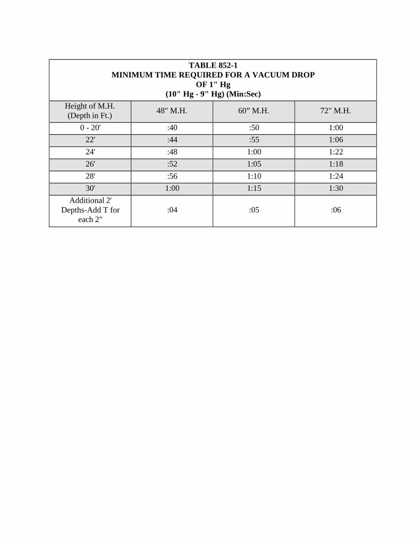
TABLE 852-1 MINIMUM TIME REQUIRED FOR A VACUUM DROP
OF 1" Hg (10" Hg - 9" Hg) (Min:Sec)
Height of M.H. (Depth in Ft.)
48" M.H.
60” M.H.
72" M.H.
0 - 20' :40 :50 1:00 22' :44 :55 1:06 24' :48 1:00 1:22 26' :52 1:05 1:18 28' :56 1:10 1:24 30' 1:00 1:15 1:30
Additional 2' Depths-Add T for
each 2"
:04
:05
:06
ITEM NO. 853 SANITARY SEWER GLASS-FIBER
REINFORCED POLYESTER (FRP) MANHOLES 853.1 DESCRIPTION: This item shall govern the construction of FRP sanitary sewer
complete in place and the material therein, including manhole ring and covers. All plans, materials and specifications shall be in accordance with the Texas Administrative Code (TAC) rules to include: 30 TAC 213.5 and design criteria for sewerage systems 30 TAC 217.53, 30 TAC 217.54, 30 TAC 217.54 and 30 TAC 217.55, or any revisions thereto as applicable.
853.2 MATERIALS:
1. FRP Manholes: All manholes shall be watertight. Glass-Fiber Reinforced
Polyester Manholes shall be a one-piece monolithic designed unit constructed of glass-fiber reinforced, supplier certified, unsaturated isopthalic polyester resin containing chemically enhanced silica to improve corrosion resistance, strength and overall performance. FRP manholes shall be manufactured in strict accordance with ASTM D-3753.
a. Exterior Surface: For a UV inhibitor the resin on the exterior
surface of the manhole shall have gray pigment added for a minimum thickness of 0.125 inches.
b. Dimension: Manholes shall be a circular cylinder, reduced at the
top to a circular manway not smaller than 30” inside diameter. Manholes shall also be produced in whole foot increments of length +/- 2 inches. Nominal inside diameter shall be 48”. Tolerance on the inside diameter shall be +/- 1%. The minimum wall thickness for all FRP manholes at all depths shall be 0.50 inches. Unless otherwise shown on the plans and details or approved by the Engineer, standard sanitary sewer FRP manholes shall be constructed on influent or effluent pipes less than 24” in diameter. The maximum vertical height of the diameter adjustment section or cone shall be 36”.
c. Configuration: The Manway reducer must provide a bearing
surface on which a standard ring and cover may be supported and adjusted to grade. The reducer shall be joined to the barrel section at the factory with resin and glass fiber reinforcement, this providing required monolithic design to prevent infiltration and/or exfiltration through the manhole.
d. Class: Manholes shall be manufactured in one class of load rating. This class shall be AASHTO H-20 wheel load.
e. Stub-outs and Connections: Several methods exist that may be
used to connect primary and secondary lines to manholes, and these shall be performed per Engineer’s request. The most common of these methods include: installation of SDR PVC sewer pipe stub-outs to manhole, Kor-N-Seal boots or Insert-a-Tee fittings in the manhole wall. Installation of SDR PVC sewer pipe must be performed by sanding, priming, and using resin fiber- reinforced hand lay-up. The resin and fiberglass shall be same type and grade as used in the fabrication of the fiberglass manhole. Kor-N-Seal boots may be installed by manhole manufacturer using fiberglass reinforced pipe stub-out for Kor-N-Seal boot sealing surface. Insert-a-Tee fittings maybe installed only with the approval of the Engineer and shall be installed per manufacturers’ instructions.
f. Manhole Bottom: Manholes are required to have resin fiber-
reinforced bottom. Deeper manholes may require a minimum of two 1½ inches deep x 3½ inches wide stiffening ribs completely enclosed with resin fiber-reinforcement. All fiberglass manholes with a fiberglass bottom will have a minimum 3 inches anti- flotation ring. Manhole bottom shall be a minimum of ½ inch thick.
g. Marking and Identification: All manholes shall be marked in
letters no less than 1 inch in height with the following information:
Manufacturer’s name or trademark Manufacturer’s factory location Manufacturer’s serial number Manhole Length ASTM Designation Installations assist marks (vertical lines 90 deg. apart at base of manhole).
2. Manhole Rings and Covers: Watertight rings and covers shall be cast iron
to the dimensions shown on details.
3. Throat Rings: Adjustment throat rings shall be precast non-reinforced concrete rings having a maximum thickness of 2 inches. The internal
diameter shall not be less than 30”, and the width shall be a minimum of 5 inches. Concrete shall conform to the provisions of Concrete (Class “A”), Item No. 300, of the City of Cibolo Specifications. No more than 4 throat rings shall be used on any manhole.
4. Mortar: Mortar shall be composed of 1 part Portland Cement, 2 parts sand
and sufficient potable water to produce a working mixture.
5. Membrane Curing Compound: All membrane curing compound shall conform to the provisions of “Membrane Curing”, Item No. 305, of the City of Cibolo Specifications.
6. Concrete Encasements: Concrete encasement shall conform to the
provisions of Concrete (Class “B”), Item No. 300, of these specifications.
7. Reinforcing Steel: All reinforcing steel shall conform to provisions of “Reinforcing Steel”, Item No. 301, of these specifications.
8. Initial Backfill Material: The initial backfill material shall be composed of
well graded, crushed stone or gravel conforming to the following requirements unless modified by the Engineer.
Crushed Stone or Gravel Percent
Passing 1½ inch sieve 100 Passing 1 inch sieve 95 to 100 Passing ⅜ inch sieve 25 to 60 Passing No. 4 sieve 0 to 10 Passing No. 8 sieve 0 to 5
9. Secondary Backfill Material: Secondary backfill material shall generally
consist of material removed from the excavation and shall be free of brush, debris and trash. No rock or stone having a dimension larger than 3½ inches at the largest dimension shall be used in the secondary backfill zone. Secondary backfill material shall be primarily composed of compactable soil material.
853.3 CONSTRUCTION:
1. Manholes shall be constructed of materials and workmanship as prescribed by these specifications, at such places shown on the plans and in conformity with the typical details.
2. Fiberglass manholes must be installed according to
manufacturer’s installation instructions. In addition to these instructions, local codes may apply and should be consulted as applicable in manhole installation. Correct manhole installation requires proper concrete foundation, good backfill and proper handling to prevent manhole damage and insure long- term corrosion resistant service.
3. Prepare excavation at manhole location should be at least wide
enough to accommodate the slab specified and to provide working room around manhole. Insure the depth of manhole is sufficient to allow at least two concrete rings for adjustment of ring and cover at top of final grade. Quarter marks have been provided on barrel to facilitate alignment.
4. Manhole Base: Use initial backfill material to provide 4 to 6 inches
of leveling base.
5. Set Manhole: To lift manhole, insert 4 inches x 4 inches timber crosswise inside the manhole to the underside of the collar with a rope or woven fabric slings attached to backhoe or other lifting device and lower the manhole. Level manhole and connect sewer lines to manhole. A concrete base encasement shall be placed at least 12 inches from the manhole and shall come over the top of the anti-flotation ring a minimum of 12 inches.
6. Invert and Bench Area: The invert and bench area can be formed with
wet concrete and finished with an epoxy sealant.
7. Backfill Material: The Contractor shall be required to backfill all manholes with an approved flowable backfill in accordance with the requirements of the right-of-way owner having jurisdiction up to 1 foot above the cone section. Secondary backfill material may be used for the remainder of the backfill. This material will be subject to approval by Engineer.
8. Secondary Backfill Procedure: Backfill shall be placed in layers of
not more than 12 loose measure inches and mechanically tamped to 98% Standard Proctor Density, unless otherwise approved by Engineer.
9. Bring to Grade: Construct reinforced concrete ring encasement
as identified on details
10. Testing:
a. Hydrostatic Testing: Hydrostatic testing shall be conducted by
plugging an approved plug into all influent and effluent pipes in the manhole and filling the manhole to the top of the manhole cone with water, Additional water may be added over a 24 hour period to compensate for evaporate losses. At the conclusion of the 24 hour saturation period the manhole shall be filled to the top of the manhole cone and observed. Any losses of water within a 30 minute period shall be considered an unsuccessful test.
b. Vacuum Testing:
1. General: Manholes shall be tested after installation and prior to
backfilling with all connections (existing and proposed) in place.
2. Test Procedure: The lines entering the manhole shall be temporarily plugged with braced plugs in order to prevent them from being drawn into the manhole. The plugs shall be installed in the lines beyond drop connections, gas sealing connections, etc. The test head shall be inflated in accordance with the manufacturer’s recommendations. A vacuum of 10 inches of mercury shall be drawn, and the vacuum pump will be turned off. With the valve closed, the level vacuum shall be read after the required test time. If the drop in the level is less than 1inch of mercury (final vacuum greater than 9 inches of mercury), the manhole will have passed the vacuum test. The required test time is determined from Table 853-1.
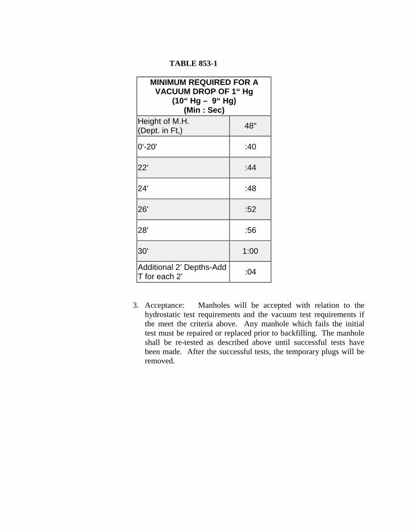
TABLE 853-1
MINIMUM REQUIRED FOR A VACUUM DROP OF 1“ Hg
(10“ Hg – 9“ Hg) (Min : Sec)
Height of M.H. (Dept. in Ft,)
48"
0'-20'
:40 22'
:44
24'
:48 26'
:52
28'
:56 30'
1:00
Additional 2’ Depths-Add T for each 2’
:04
3. Acceptance: Manholes will be accepted with relation to the hydrostatic test requirements and the vacuum test requirements if the meet the criteria above. Any manhole which fails the initial test must be repaired or replaced prior to backfilling. The manhole shall be re-tested as described above until successful tests have been made. After the successful tests, the temporary plugs will be removed.
ITEM NO. 854 SANITARY SEWER LATERALS
854.1 DESCRIPTION: This item shall consist of sanitary sewer laterals installed in
accordance with these specifications and as directed by the Engineer. This item shall also consist of installation of one way sewer cleanout at the property line.
854.2 MATERIALS: The materials for sanitary sewer laterals shall conform to the
specification contained in "Sanitary Sewers", Item No. 848. 854.3 CONSTRUCTION:
1. Sanitary sewer laterals fittings and appurtenances shall conform to the
material specifications and shall be installed by the Contractor as specified herein, or as directed by the Construction Inspector or the Engineer and in accordance with the Standard Drawings DD-854 Series.
2. Designation of Lateral: A sewer pipe located between the sanitary sewer
main and the customers premise is designated as a "sanitary sewer lateral".
3. Service line Installation: All service line installations shall be performed in accordance with "Sanitary Sewers", Item No. 848, and "Excavation, Trenching and Backfill", Item No. 804, and as described herein. For sanitary sewer mains that are 12” in diameter or smaller, all laterals shall be connected using the appropriate size tee/wye placed in line with the main line. For mains larger than 12", insert-a-tee conforming to ASTM 3034-88 or approved or equal may be used.
Connection to the Customers end of the lateral shall be performed using a
"Fernco coupling" or approved equal. All Cleanouts at job sites shall have installed an approved heavy duty sanitary sewer cap, in accordance with the Standard Drawings DD-854.1 Series. Cutting, excavation, and backfill shall be as specified herein and in accordance with applicable sections of "Excavation, Trenching, Backfill", Item No. 804.
ITEM NO. 855 RECONSTRUCTION OF EXISTING MANHOLES
855.1 DESCRIPTION: This item shall consist of the reconstruction of all existing
manholes, all types and sizes, to include the replacement of manhole rings and covers, the replacing of existing cone, manhole section or sections required regardless of type shown on the plans and in conformity with the provisions of these specifications. Existing Monolithic Manholes are not be reconstructed but replaced under the bid item for Sanitary Sewer Manholes or Structures. All manholes shall be watertight and the interior walls coated with an approved sewer structural coating.
855.2 CONSTRUCTION: Manholes shall be raised or lowered by replacing the
existing cone and manhole section or sections as required for installation to the finished surface course. All openings shall be protected by hatch covers or the necessary steel plates. The Contractor shall be required to backfill all manholes with an approved flowable backfill in accordance with the requirements of the right-of-way owner having jurisdiction up to 1 foot above the cone section.
Reconstructed Manholes shall also be cleaned of any debris as required by the Cibolo Inspector. If a new manhole cover, ring, or reconstructed manhole is damaged by the Contractor, it shall be replaced by the Contractor at his expense. If concrete throat rings are to be installed they must be used in conjunction with a UV stabilized polyethylene liner and I/I barrier. I/I barrier must meet the following ASTM standards: ASTM D-790/1505 Density of Polyethylene Materials, ASTM D1238 Melt Flow index, ASTM 638 Tensile Strength @ Yield (50mm/mm), ASTM 790 Flexural Modulus, ASTM 648 Heat Deflection temperature @IGEPAL, ASTM 1693 EsCR, 100% IGEPAL/10% IGEPAL.
Material excavation from around the manholes shall be replaced with concrete in accordance with Standard Drawings, and select materials from the excavation (as shown on the plans or specified by the SAWS). All excess materials (of any type) shall be disposed of by the Contractor at his own expense and in an approved location.
All reconstructed existing manholes shall be watertight and the interior walls coated with an approved sewer structural coating. For reconstructed existing manholes, apply a combination of both products with the cementitious coating first, followed by the epoxy coating. Lafarge SewperCoat 2000 HR regular, with the required one inch thick application, is the only product yet approved which satisfies the requirement of applying the combination of both the cementitious coating and epoxy coating. Approved materials are as follows:
Cementitious coating: With required one inch thick application. • Permacast CR-5000 • Strong - Seal MS-2C • Standard Cement Material Inc. Reliner • Quadex Aluminaliner
Epoxy coating: With specified thickness application.
• Raven 405 Series High Build Epoxy Liner: Required thickness 125 mils
• Spray Wall polyurethane System: Required thickness 150 mils
ITEM NO. 856 JACKING, BORING OR TUNNELING PIPE
856.1 DESCRIPTION: This item shall govern the furnishing and installation of pipe
by the methods of jacking, boring, or tunneling as shown on the plans and in conformity with this specification.
856.2 MATERIALS:
1. Carrier Pipe shall be of the types and sizes shown on the plans and shall
conform to the requirements of these specifications. If PVC pipe is to be utilized as carrier pipe, installation shall conform to Item No. 818 and/or Item No. 819, of the Construction Standard Specifications and shall be fully restrained in casing. For sanitary sewers, materials shall conform to Items No. 848.2.a, through 848.2.f, or as specified on the plans by Engineer, and in accordance with the Standard Drawings DD-856 Series.
2. Casing Pipe, if required, shall be as follows for water mains:
a. RCP; b. steel; and c. liner plate.
3. Grout: Grout for annular spaces shall be sand cement slurry containing a
minimum of 7 sacks of Portland Cement per cubic yard of slurry. All slurry shall be plant batched and transit mixed.
856.3 CONSTRUCTION:
1. Jacking: Suitable pits or trenches shall be excavated for the purpose of
jacking operations for placing end joints of the pipe. When trenches are cut in the side of embankment, such work shall be securely sheeted and braced. Jacking operations shall in no way interfere with the operation of railroads, streets, highways or other facilities and shall not weaken or damage such facilities. Barricades and lights shall be furnished as directed by the Engineer to safeguard traffic and pedestrians.
The pipe to be jacked shall be set on guides to support the section of pipe being jacked and to direct it in the proper line and grade. Embankment material shall be excavated just ahead of the pipe and material removed through the pipe, and the pipe forced through the opening thus provided.
The excavation for the underside of the pipe, for at least ⅓ of the circumference of the pipe, shall conform to the contour and grade of the pipe. A clearance of not more than 2 inches may be provided for the upper
half of the pipe.
The distance that the excavation shall extend beyond the end of the pipe shall depend on the character of the material, but it shall not exceed 2 feet in any case.
Generally, the pipe shall be jacked from downstream end. Permissible lateral or vertical variation in the final position of the pipe from line and grade will be as shown on the plans or as determined by the Engineer.
Any pipe that cannot be repaired to its original condition or is damaged in jacking operations shall be removed and replaced at the Contractor's expense. Jacking pits shall be backfilled immediately upon completion of jacking operations.
2. Excavation for "Boring" pits and installation of shoring shall be as outlined under "Jacking." Boring operations may include a pilot hole which shall be bored the entire length of crossing and shall be used as a guide for the larger hole to be bored. Water or drilling fluid may be used to lubricate cuttings. Variation in line and grade shall apply as specified under "Jacking."
3. Tunneling: Tunneling may be used when the size of the proposed pipe or
the use of a monolithic sewer would make the use of tunneling more satisfactory than "Jacking" or "Boring." The excavation for pits and the installation of shoring shall be as specified under "Jacking."
The lining of the tunnel shall be of the material shown on the plans.
Access holes for grouting annular space shall be spaced a maximum of 10 feet.
4. Joints: Joints for pipe for "Jacking," "Boring," or "Tunneling,” shall be as
specified in "Sanitary Sewers", Item No. 848, or as shown on the project plans or shop drawings as per pipe manufacturer's recommendation.
5. Grouting of Bores or Tunnels: Annular Space between casing pipe and
limits of excavation (borehole) shall be pressure grouted, unless otherwise specified on the plans.
ITEM NO. 858 CONCRETE ENCASEMENT, CRADLES, SADDLES AND COLLARS
858.1 DESCRIPTION: This item shall govern placing concrete encasements, cradles,
saddles, collars, when called for by the project plans or as directed by the Engineer.
858.2 MATERIALS:
Concrete: All concrete shall conform to the provisions of "Concrete (Class B)", Item No. 300, shall be of the class as noted on the plans.
858.3 CONSTRUCTION:
1. Concrete Encasement: When concrete encasement is shown on the plans
or when directed by the Engineer, the trench shall be excavated and fine graded to a depth conforming to details and sections shown on the plans, or Standard Drawing DD-858. The pipe shall be supported by precast concrete blocks of the same strength as the concrete for encasement and securely tied down to prevent floatation. Encasement shall then be placed to a depth and width conforming to details and sections shown on the plans.
2. Concrete Cradles: When concrete cradles are shown on the plans or when
called for by the Engineer, the trench shall be prepared and the pipe supported in the same manner as described in Paragraph 858.3.1, of this specification and shall be constructed in accordance with details and sections shown on the plans. Straps/Tie Downs shall be of No. 4 rebar diameter minimum or better as determined by Cibolo Inspector.
3. Concrete Saddles: When shown on the plans or when directed by the
Engineer, pipe to receive concrete saddles shall be backfilled in accordance with "Excavation, Trenching and Backfill", Item No. 804, to the spring line and concrete placed for a depth and width conforming with details and sections shown on the plans.
4. Concrete Collars: When shown on the plans or when directed by the
Engineer, concrete collars shall be constructed in accordance with details and sections shown on the plans.
ITEM NO. 860 VERTICAL STACKS
860.1 DESCRIPTION: This item shall govern the construction of vertical stacks from
the main sewer line. 860.2 MATERIALS:
1. Pipe: Pipe and fittings shall conform to the requirements of "Sanitary
Sewers", Item No. 848.
2. Concrete Encasement: Concrete encasement shall conform to the requirements of "Concrete Encasement, Cradles, Saddles and Collars", Item No. 858.
860.3 CONSTRUCTION: All work performed under this item shall conform to the
applicable provisions of "Sanitary Sewers", Item No. 848, and the details shown on the project plans. Generally, vertical stacks for sewer laterals shall be installed where the depth of the main line invert to the finished grade is greater than eight feet or where specified by the Inspector.
ITEM NO. 862 ABANDONMENT OF SANITARY SEWER MAIN AND MANHOLES
862.1 DESCRIPTION: This item shall govern the abandonment of sanitary sewer
mains and manholes required on the plans to be abandoned. Generally, sanitary sewers over 12" in diameter and all abandoned sanitary sewer manholes are to be filled with a cementious low strength material. The sanitary sewer facility shall be abandoned in accordance with the specifications herein outlined and in conformity with the limits shown on the plans.
Abandoning of sanitary sewer lines & manholes shall not occur until all existing sanitary sewer services are transferred to another line & directed by the Engineer.
862.2 MATERIALS: Materials for abandonment of sanitary sewer pipe and manholes.
1. Sanitary Sewer Pipe: A cement based grout shall be used to fill the void of the existing sanitary sewer main. The grouting material must have a strength of at least 100 psi and shall have flow characteristics appropriate for filling a sanitary sewer. The grout mix designed and method of installation shall be approved by the Engineer prior to beginning operation.
2. Material for Abandoning Manholes: The sanitary sewer manhole shall be filled to the top of the remaining concrete structure with the same material used to abandon the sanitary sewer line.
862.3 CONSTRUCTION: Abandonment of sanitary sewer lines shall be accomplished by installing the grout material with sufficient pressure and in numerous locations. The method of installation shall be able to meet the requirement of completely filling the existing sanitary sewer line and any voids adjacent to the sanitary sewer line. The method shall adequately provide for the removal and legal disposal of existing sewer materials in the system. The method shall provide for the release of air. When intermediate points are required to be constructed for the abandonment of the system, they shall be a part of the abandonment project process.
Sanitary sewer pipes smaller than 15" in diameter, are generally not required to be grouted unless it is required by the plans. Pipes to be abandoned shall be grouted only if required by the plans and payment as per these specifications is provided.
The concrete structure of the manhole shall be removed to a depth of 2 feet under proposed subgrade or finished ground elevation. Manhole rings and covers shall be removed and delivered to a facility designated by the City.
ITEM NO. 864 BYPASS PUMPING
864.1 DESCRIPTION: The work covered by this item consists of; furnishing all labor,
supervision, tools, equipment, appliances, and materials to perform all operations in connection with pumping sewage and wet weather flows around pipe segment(s). The purpose of bypass pumping is to prevent sewage overflows and provide reliable sewer at all times. The Contractor shall maintain sewage flow in the construction area in order to prevent backup and/or overflow into upstream pipe segments and laterals, adjacent ditches, storm sewers, and waterways.
864.2 MATERIALS: The Contractor shall provide and maintain adequate pumping
equipment, force mains and other necessary appurtenances in order to maintain reliable sanitary sewer service in all sanitary sewer lines as required for construction. The Contractor shall have backup pump(s), force main(s) and appurtenances ready to deploy immediately. Appurtenances and discharge point shall be approved by the Inspector.
Any spillage, backups and/or overflows, etc. as the result of inadequate equipment are the sole responsibility of the Contractor.
The Contractor shall demonstrate that the pumping system is in good working order and is sufficiently sized to successfully handle flows by performing a test run for a period of 24 hours prior to beginning the work.
The Contractor shall be required to have all materials, equipment and labor necessary to complete the repair or replacement on the job site prior to isolating the sewer manhole or line segment and beginning bypass pumping operations.
864.3 CONSTRUCTION: The Contractor shall provide bypass pumping of sewage
and wet weather flows around each segment(s) of pipe that is to be replaced. The Contractor will be required to provide in writing a sequence of bypass pumping for review and approval by the Inspector. Refer to the construction plans for the construction phasing and diversion requirements. The Contractor shall also provide the Inspector a sketch showing the location of bypass pumping equipment for each line segment(s) around which flows are being bypassed. The Contractor shall be responsible for all required bulkheads, pumping, equipment, piping, etc., to accomplish the sequence of pumping. The Contractor shall cease bypass pumping operations and return flows to the new and/or existing sewer when directed by the Inspector. All piping(s), joints and accessories shall be designed to withstand at least twice
the maximum system pressure, or a minimum of 50 psi whichever is greater. During bypass pumping, no sewage shall be leaked, dumped, or spilled in or unto, any area outside of the existing sanitary sewer system. When bypass pumping operations are complete, all pumping shall be drained into the sanitary sewer prior to disassembly.
864.4 PUMP OPERATION:
1. The Contractor shall plug off and pump down the sewer manhole or line segment in the immediate work area and shall maintain the sanitary sewer system so that surcharging does not occur. Where work requires the line to be blocked beyond working hours, Contractor shall operate bypass pumping and man the system 24 hours a day.
2. The Contractor shall ensure that no damage will be caused to private
property as a result of bypass pumping operations. Ingress and egress to adjacent properties shall be maintained at all times. Ramps, steel plates or other methods shall be deployed by the Contractor to facilitate traffic over surface piping. High traffic commercial properties may require alternate methods.
3. The Contractor shall complete the work as quickly as possible and satisfactorily pass all tests, inspections and repair all deficiencies prior to discontinuing bypass pumping operations and returning flow to the sewer manhole or line segment.
4. The Contractor shall immediately notify the Inspector should a surcharge occur that results in an overflow of sewage. If the Contractor is unable to remedy the situation, then he should suspend or terminate the work until such time as the overflows have been controlled. Should such surcharge damage the materials and/or equipment that are used on the job and/or adjacent property, it shall be corrected at no additional cost to the City.
In the event that sewage accidentally drains into the drainage system or street, the Contractor shall immediately stop the overflow, notify the Inspector, and take the necessary action to clean up and disinfect the spillage to the satisfaction of the Engineer. If sewage is spilled onto public or private property, the Contractor shall wash down, clean up and disinfect the spillage to the satisfaction of the Engineer.
The Contractor shall locate bypass pumping suction and discharge lines so as to not cause undue interference with the use of streets, private
driveways and alleys. In cases where the suction and or discharge lines are required to be buried for vehicle/pedestrian traffic, cost for this work is incidental and includes complete restoration of any surface features disturbed. Force main piping may be laid inside of storm drainage pipes to avoid surface interference with vehicular or pedestrian traffic. Flows shall not be allowed to spill from said force mains into said drainage pipes. The use of existing storm drain systems shall be approved by the City Engineer. Force mains laid in storm sewers shall be pressure pipe and fittings.
The Contractor shall not intentionally damage or remove portions of existing storm sewer system structures or sanitary sewer structures for the purpose of installing bypass pumping system without specific approval from the Inspector. If a structure is damaged, it shall be reconstructed or replaced to the satisfaction of the Engineer.
The City of Cibolo shall not be responsible for any damage to the bypass pumping system sustained by the Contractor directly or indirectly as a result of storm water runoff within streets, ditches and/or storm sewer systems. The Contractor shall be responsible for any and all damage that results directly or indirectly from the interference of storm water runoff to bypass pumping equipment, piping and/or appurtenances. It is the intent of these specifications to require the Contractor to establish adequate bypass pumping as required regardless of the flow conditions.
ITEM 866 SEWER MAIN TELEVISION INSPECTION
866.1 DESCRIPTION:
The Contractor shall furnish all labor, materials, equipment, and incidentals to provide the televising and a NASSCO-(PACP) standard video, recorded in MPEG-1 format and written to DVD video, of sewer lines and manholes utilizing a color, closed-circuit television inspection unit to determine their condition.
866.2 GENERAL:
After construction of the sanitary sewer main and prior to placement of the final course of asphalt, the newly constructed sanitary sewer shall be televised immediately upon cleaning. Televising shall be observed by the Inspector, Engineering personnel and contractor as the camera is run through the system. Any abnormalities such as, but not limited to, misaligned joints, cracked/defected pipe, rolled gaskets, shall be repaired by the contractor at his expense. Sections requiring repair shall be re-televised to verify condition of repair. No additional compensation shall be provided for repair or re-televising.
866.3 EXECUTION:
Prior to Preliminary Acceptance, the Contractor shall provide a DVD and logs of the televised inspection for review. If the Contractor provides a DVD of such poor quality that it cannot be properly evaluated, the Contractor shall re-televise as necessary and provide a DVD of good quality at no additional cost to t he C i t y o f C ibo lo . If the Contractor cannot provide a DVD of such good quality that can be reviewed by the City, the City may elect to televise the line at the Contractor's expense.
The television unit shall also have the capability of displaying in color, on DVD, pipe inspection observations such as pipe defects, sags, points of root intrusion, offset joints, service connection locations, and any other relevant physical attributes. Each DVD shall be permanently labeled with the following:
Project name Date of television inspection; Station to station location and size of sanitary sewer; Street/easement location; Name of Contractor; Date DVD submitted; and DVD number.
The Contractor shall provide a line diagram area sketch and written log for each completed segment of DVD sewer main describing the section being televised, flow and camera direction, position of service connections, description and location of failures, pipe condition, weather conditions, and other significant observations.
The television inspection equipment shall have an accurate footage counter which displays on the monitor the exact distance of the camera from the center of the starting manhole. A camera with rotating and panning lens capabilities is required. The camera height shall be centered in the conduit being televised. The speed of the camera through the conduit shall not exceed 40 feet per minute.
The Contractor shall be required to have all materials, equipment, and labor force necessary to complete all videotaping on the job site prior to isolating the sewer manhole segment and beginning videotaping operations.
Television inspection shall be done one manhole section at a time. Also the flow in the section being televised shall be bypassed if the line is in service and the flow exceeds 25% of the internal pipe diameter. When the depth of flow at the upstream manhole of the manhole section being worked is above the maximum allowable for television inspection, the flow shall be reduced to allowable levels by temporarily plugging or blocking the flow or bypass pumping, as approved by the City of Cibolo.
The Contractor shall not be allowed to float the camera. There may be occasions during the televised inspection of a manhole section when the camera will be unable to pass an obstruction. At that time, and prior to proceeding, the Contractor shall contact the Inspector. If the length of sewer line cannot be televised because of obstructions, the Contractor shall clean the system as is necessary. If, in the opinion of the Inspector, the obstruction is attributed to a collapsed main or pipe deflection, televising shall be suspended, payment shall be made based on the actual televised length, and the remaining televising of the sewer line shall be continued upon successful correction of the blockage by the Contractor at his expense. No additional payment shall be made for additional setups required due to obstructions encountered during televising.
The Contractor is solely responsible for any damage of sewer mains as a direct result of televising operations. Any repair shall also be the responsibility of the Contractor. The method(s) used for securing passage of the camera are at the discretion of the Contractor, as approved by the City of Cibolo. No separate and/or additional payment will be made for any excavation, man entry, or any other method which may be required to retrieve video equipment that may have been hung up, destroyed, and/or lost during the operation.
866.4 SEWER MAIN BYPASS PUMPING:
The Contractor shall perform bypass pumping operations in accordance with Item No. 864 and as outlined below.
The Contractor shall furnish all labor, supervision, tools, equipment, appliances, and materials to perform all operations in connection with bypass pumping of sewage flow for the purpose of preventing interference with the televising of the sanitary sewer manholes and mainlines as well as providing reliable sewer service to the occupants of the buildings being served.
The Contractor will be required to provide adequate pumping equipment and force mains in order to maintain reliable sanitary sewer service in all sanitary sewer lines involved in this project. The Contractor shall notify the Inspector should a surcharge occur during the televising process which results in overflows of sewage. In case of bypass equipment failure, the Contractor shall discontinue work and release sewer flows until such time as equipment failure is corrected. The location of the pump(s), force main(s), and discharge points shall be approved by the City of Cibolo. Under no circumstances shall the flow be interrupted or stopped, such that damage is done to either private or public property, or sewage flows or overflows into a storm sewer or natural waterway.
The Contractor shall provide bypass pumping of sewage around each segment(s) of pipe that is to be televised and shall be responsible for all required bulkheads, pumps, equipment, piping, and other related appurtenances to accomplish the sequence of pumping. A qualified person shall man the pumps, on-site, at all times during the bypassing procedure.
All piping, joints, and accessories shall be designed to withstand the maximum bypass system pressure, or a minimum of 50 psi, whichever is greater. During bypass pumping, no sewage shall be leaked, dumped, or spilled into or onto any area outside of the existing sanitary sewer system. When bypass pumping operations are complete, all piping shall be drained into the sanitary sewer prior to disassembly. The Contractor shall demonstrate that the pumping system is in good working order and can successfully handle flows during cleaning and televising operations, prior to commencing with the cleaning and televising of the system.
866.5 MATERIALS REQUIRED FOR BYPASS OPERATION:
The Contractor shall be required to have all materials, equipment, and labor necessary to complete the repair or replacement on the jobsite prior to isolating the sewer manhole or line segment and beginning bypass pumping operations.
866.6 TRAFFIC CONSIDERATIONS:
The Contractor shall locate bypass pumping suction and discharge lines so as to not cause undue interference with the use of streets, private driveways, and alleys to include the possible temporary trenching of force mains at critical intersections. Traffic management shall be done under the approval of respective City, County, or State government agencies. The Contractor shall not open cut existing streets to accommodate bypass pumping piping unless written approval is given.
866.7 PUMP OPERATIONS:
The Contractor shall plug off and pump down the sewer manhole and/or line segment in the immediate work area and shall maintain the sanitary sewer system so that surcharging does not occur. The Contractor shall coordinate with all property owners to ensure that no damage will be caused to their property during any and all sewer rehabilitation work. The Contractor shall complete the televising as quickly as possible and shall satisfactorily meet all requirements prior to discontinuing bypass pumping operations and returning flow to the sewer manhole or line segment. The Contractor shall ensure that no damage will be caused to private property as a result of bypass pumping operations. Ingress and egress to adjacent properties shall be maintained at all times. Ramps, steel plates, or other methods shall be employed by the Contractor to facilitate traffic over surface piping. There will be no separate pay item for this work.
In the event that sewage accidentally drains into the drainage system or is spilled within the project, the Contractor shall immediately stop the overflow, notify the Inspector, and take the necessary action to clean up and disinfect the spillage using an HTH, or equal, chemical, at no cost to the City of Cibolo.
ITEM NO. 868 SEWER MAIN CLEANING
868.1 SCOPE:
The Contractor shall furnish all labor, equipment, appliances, and materials necessary for cleaning the sewer system including the removal of all debris, solids, sand, grease, grit, etc. from the sewer and manholes to facilitate television inspection.
868.2 DESCRIPTION:
The Contractor shall be required to have all materials, equipment, and labor necessary to complete the cleaning of the sanitary sewer main and manholes on the jobsite prior to isolating the sewer manhole or line segment and beginning the cleaning process.
The Contractor shall only use the type of cleaning material which will not create hazards to health or property or affect treatment plant processes.
The sanitary sewer lines and structures shall be cleaned using mechanical, hydraulically-propelled, and/or high velocity sewer cleaning equipment. The cleaning process shall remove all grease, sand, silts, solids, rags, debris, etc. from each sewer segment, including the manhole(s). Selection of cleaning equipment and the method for cleaning shall be based on the condition of the sanitary sewer mains at the time work commences and will be subject to City of Cibolo approval. All cleaning equipment and devices shall be operated by experienced personnel. Satisfactory precautions shall be taken to protect the sanitary sewer mains and manholes from damage that might be inflicted by the improper use of the cleaning process or equipment. Any damages done to a sewer main and/or structure by the Contractor shall be repaired by the Contractor at no additional cost and to the satisfaction of City of Cibolo. Cleaning shall also include the manhole wall washing by high pressure water jet.
1. Hydraulic Cleaning:
Hydraulic-propelled devices which require a head of water to operate must utilize a collapsible dam. The dam must be easily collapsible to prevent damage to the sewer main, property, etc. When using hydraulically- propelled devices, precautions shall be taken to insure that the water pressure created does not cause damage or flood public or private
property. The Contractor shall not increase the hydraulic gradient of the sanitary sewers beyond the elevation that could cause overflow of sewage into area waterways or laterals. The flow of wastewater present in the sanitary sewer main shall be utilized to provide necessary fluid for hydraulic cleaning devices whenever possible.
2. High Velocity Cleaning:
Cleaning equipment that uses a high velocity water jet for removing debris shall be capable of producing a minimum volume of 50 gpm, with a pressure of 1,500 psi, for the sanitary sewer line and 3,500 psi for the (manhole) structure at the pump. Any variations to this pumping rate must be approved, in advance, by the C i ty o f C ibo lo . To prevent damage to older sewer mains and property, a pressure less than 1500 psi can be used. A working pressure gauge shall be used on the discharge of all high pressure water pumps. The Contractor shall use, in addition to conventional nozzles, a nozzle which directs the cleaning force to the bottom of the pipe for sewers 18" and larger in diameter. The Contractor shall operate the equipment so that the pressurized nozzle continues to move at all times. The pressurized nozzle shall be turned off or reduced anytime the hose is on hold or delayed in order to prevent damage to the line.
3. Mechanical Cleaning:
Mechanical cleaning, in addition to normal cleaning when required, shall be with approved equipment and accessories driven by power winching devices. The Contractor shall submit the equipment manufacturer's operational manual and guidelines to the Engineer, which shall be followed strictly unless modified by the Engineer. All equipment and devices shall be operated by experienced operators so that they do not damage the pipe in the process of cleaning. Buckets, scrapers, scooters, porcupines, kites, heavy duty brushes, and other debris-removing equipment/accessories shall be used as appropriate and necessary in the field, in conjunction with the approved power machines. The use of cleaning devices such as rods, metal pigs, porcupines, root saws, snakes, scooters, sewer balls, kites, and other approved equipment, in conjunction with hand winching device, and/or gas, electric rod propelled devices, shall be considered normal cleaning equipment.
868.3 GENERAL REQUIREMENTS:
In addition to the requirements herein, the Contractor shall maintain a clean work and surrounding premises within the work limits so as to comply with Federal, State, and local environmental and anti-pollution laws, ordinances, codes, and
regulations when cleaning and disposing of waste materials, debris, and rubbish. The contractor shall also keep the work and surrounding premises within work limits free of accumulations of dirt, dust, waste materials, debris, and rubbish. Suitable containers for storage of waste materials, debris, and rubbish shall be provided until time of disposal. It is the sole responsibility of the Contractor to secure a licensed legal dump site for the disposal of this material. Under no circumstances shall sewage or solids removed from the main or manhole be dumped onto streets or into ditches, catch basins, storm drains, or sanitary sewers. Cost for this item shall be included in the price bid for sanitary sewer manhole and mainline cleaning.
The Contractor may be required to demonstrate the performance capabilities of the cleaning equipment proposed for use on the project. If the results obtained by the proposed sanitary sewer cleaning equipment are not satisfactory, the Contractor shall use different equipment and/or attachments, as required, to meet specifications. More than one type of equipment/attachments may be required at a location. When hydraulic or high velocity cleaning equipment is used, a suitable sand trap, weir, dam, or suction shall be constructed in the downstream manhole in such a manner that all the solids and debris are trapped for removal.
Whenever hydraulically-propelled cleaning tools which depend upon water pressure to provide their cleaning force, or any tool which retard the flow of water in the sanitary sewer lines are used, precautions shall be taken to insure that the water pressure created does not cause any damage or flooding to public or private property being served by the manhole section involved. Any damage of property, as a result of flooding, shall be the liability and responsibility of the Contractor. The flow of wastewater present in the sanitary sewer main shall be utilized to provide necessary fluid for hydraulic cleaning devices whenever possible. When additional quantities of water from fire hydrants are necessary to avoid delay in normal working procedures, the water shall be conserved and not used unnecessarily. No fire hydrant shall be obstructed or used when there is a fire in the area. The Contractor shall be responsible for obtaining the water meter and all related charges for the set-up, including the water usage bills from respective water purveyor agency. All expenses shall be considered incidental to the cleaning of the existing sanitary sewer mains.
ITEM NO. 869 PROJECT SIGNS
869.1 DESCRIPTION: This item shall consist of providing, installing, maintaining and
removing two 4' X 8' project signs (at the completion of the project). The signs shall conform to the configuration and details indicated in Drawing No. DD-845- 02. These signs shall be installed at locations to be determined by the Project Engineer. Any additional signs required by other agencies shall also be installed wherever necessary.
869.2 MATERIAL: The signs shall be made of ¾" plywood, grade A-C or better and
each shall be mounted on two 4" X 4" X 12'-0" posts. 869.3 INSTALLATION: The installation will require embedding all posts a minimum
of 3'-0" below the ground.
ITEM NO. 900 RECONSTRUCTION OF SANITARY SEWER BY PIPE BURSTING/CRUSHING REPLACEMENT PROCESS
900.1 DESCRIPTION: This specification includes requirements to rehabilitate existing sanitary sewers by pipe bursting/crushing method. The pipe bursting/crushing process is defined as the reconstruction of existing sanitary sewers by the simultaneous insertion (breaking and expanding the old pipe) of liner pipe within the bore of the existing pipe. Also covered in this specification is pipe, pipe joining, manhole connections, connection of service laterals and stubs, point repairs, obstruction removals, television requirements, testing requirements, bypass pumping criteria, site restoration, erosion control requirements, and warranty requirements.
The pipe bursting/crushing process involves the rehabilitation of deteriorated gravity sewer pipe by installing new pipe material within the enlarged bore created by the use of using a static, hydraulic, or pneumatic hammer "moling" device, suitably sized to break the existing pipe or by using a modified boring "knife" with a flared plug that crushes the existing sewer pipe. Forward progress of the "mole" or the "knife" may be aided by hydraulic equipment or other apparatus. Replacement pipe is either pulled or pushed into the bore. Sewer services are reconnected to the new pipe through small excavations from the surface. Sewage flows from the upstream line and from the services are pumped as required to prevent overflows and provide continual service. All excavations required for reconnecting and pumping service flows, entry pits, exit pits, obstruction removal, point repairs, among others, are to be kept to a minimum and all damage to surface and underground features, facilities, utilities and improvements are to be repaired.
900.2 MATERIALS
1. High density polyethylene pipe (HDPE) related to pipe bursting or pipe
crushing for a sanitary sewer or related pipe line habilitation:
a. Solid wall HDPE pipe referred to as Drisco 1000, Drisco 8600, Quail Pipe, Poly Pipe, and Plexco Pipe that is in conformance with ASTM F714 and ASTM requirements stated herein are considered approved for this project. HDPE pipe on this project will further be required to have a minimum pipe stiffness of 46 psi for 12” to 48” diameter pipe and 115 psi for 8” to 10” diameters as required by the City of Cibolo and TCEQ.
Pipe Manufacturer: All pipe and fittings will be high density polyethylene
pipe and made of virgin material. No rework except that obtained from the manufacturer's own production of the same formulation will be used. The liner material will be manufactured from a high density high molecular weight polyethylene compound which conforms to ASTM D 1248 and meets the requirements for Type III, Class C, Grade P-34, Category 5, and has a PPI rating of PE 3408.
b. The pipe produced from this resin will have a minimum cell Classification
of 345434C (Inner wall will be light in color) under ASTM D 3350. A higher number cell classification limit which gives a desirable higher primary property, per ASTM D 3350 may also be accepted by the Engineer at no extra cost to SAWS. The value for the Hydrostatic Design basis will not be less than 1600 PSI (11.03 MPA) per ASTM D 2837. Pipe will have ultraviolet protection.
c. Pipe Color and Quality: For television inspection purposes, the polyethylene
pipe will have light-colored interior achieved with a homogenous, light- colored material throughout or with a fully bonded light-colored interior liner meeting specifications above indicated. All pipes shall be free of visible cracks, holes, foreign material, foreign inclusions, blisters, or other deleterious or injurious faults or defects. Pipe and fittings shall be as uniform as commercially practical in color, opacity, density, and other physical properties.
For interior lined pipe, the liner will be a minimum of 10 mils thick and co- extruded. The bond between the layers will be strong and uniform. It will not be possible to separate the two layers with a probe or point of a knife blade so that the layers separate cleanly at any point, nor will separation of the bond occur, between layers, during testing performed under the requirements of this specification.
d. Pipe Diameter: Polyethylene plastic pipe will meet the applicable requirements of ASTM F 714 Polyethylene (PE) Plastic Pipe (SDR-PR) Based on Outside Diameter, ASTM D 1248, and ASTM D 3550. Internal diameter of the pipe indicated on the plans will be the minimum allowable pipe size.
e. Pipe Dimension Ratios: The minimum wall thickness of the polyethylene pipe will meet the following, as based on the deepest portion of a particular pipe pull, typically between manholes:
Depth of Cover (Feet) Minimum SDR of Pipe 0 - 16.0 19 >16.1 17
Wall thickness shall be as indicated on the plans and will be in accordance with Chevron Plexco Industrial Piping System Pipe Data and Pressure Ratings Bulletin 301, or approved equal.
f. Pipe Joining: Solid wall pipe shall be produced with plain end construction for heat-joining (butt fusion) conforming to ASTM D 2657.
The polyethylene pipe will be assembled and joined at the site using the thermal butt-fusion method to provide a leak proof and structurally sound joint. Threaded or solvent-cement joints and connections are not permitted. All equipment and procedures used will be used in strict compliance with the manufacturer's recommendations. Fusing will be accomplished by personnel certified as fusion technicians by a manufacturer of polyethylene pipe and/or fusing equipment.
The butt-fused joint will be true alignment and will have uniform roll back beads resulting from the use of proper temperature and pressure. The joint surfaces will be smooth. The fused joint will be watertight and will have tensile strength equal to that of the pipe. All joints will be subject to acceptance by the Engineers and/or his representative prior to insertion. All defective joints will be cut out and replaced at no cost to the City of Cibolo. Any section of the pipe with a gash, blister, abrasion, nick, scar, or other deleterious fault greater in depth than 10% of the wall thickness, will not be used and must be removed from the site. However, a defective area of the pipe may be cut out and the joint fused in accordance with the procedures stated above. In addition, if in the opinion of the Engineers and/or his representative any section of pipe has other defects, including those hereinafter listed, that may indicate damaged, improperly manufactured, faulty, or substandard pipe, said pipe will be discarded and not used. Defects warranting pipe rejection include the following: concentrated ridges, discoloration, excessive spot roughness, and pitting; insufficient or variable wall thickness; pipe damage from bending, crushing, stretching or other stress; pipe damage that impacts the pipe strength, the intended use, the internal diameter of the pipe, internal roughness characteristics; or any other defect of manufacturing or handling.
Clamps & Gaskets: Clamps shall be stainless steel, including bolts & lugs as manufactured by JCM Industries Type 108 or equal. Furnish full circle, universal clamp couplings with a minimum 3/16 inch thick neoprene,
grid-type gasket. Select clamps to fit outside diameter of pipe. Use minimum clamp length of 30 inches for replacement pipes O.D. of 10.75” (10” nominal) or greater &18 inches for replacement pipe O.D. less than 10.75”.
Terminal sections pipe that are joined within the insertion pit will be connected with a full circle pipe repair clamp. The butt gap between pipe ends will not exceed ½ inch.
g. Force Mains: Where applicable, solid wall pipe for sanitary sewer force mains shall have a minimum working pressure rating of 150 psi, and an inside diameter equal to or greater than the nominal pipe size indicated on the Drawings.
h. Augering Pipe: HDPE pipe is not approved in applications requiring augering of sewer pipe.
i. Pipe Marking: Each standard and non-standard length of pipe or fitting shall be clearly marked with pipe size, pipe class, production code, material designation and other relevant identifying information.
j. Pipe Inspections: The Engineer reserves the right to inspect pipes or witness pipe manufacturing. Such inspection shall in no way relieve the manufacturer of the responsibilities to provide products that comply with the applicable standards and these Specifications. Should the Engineer wish to witness the manufacture of specific pipes, the manufacturer shall provide the Engineer with adequate advance notice of when and where the production of those specific pipes will take place. Approval of the products or tests is not implied by the Engineer’s decision not to inspect the manufacturing, testing, or finished pipes.
900.3 CONSTRUCTION
1. Pit Location: Location and number of insertion or launching pits will be chosen by the contractor, and will typically be located near existing or proposed manholes, P.I.’s in the line, at logical breaks in the construction phasing, or at locations to comply with access or maintenance requirements.
Pits shall be placed and located to minimize the total number of pulls and maximize the length of pipe replaced per pull, within the constraints of maintaining service and access and other requirements. Use excavations at point repair locations for insertion pits where possible.
2. Operations: The contractor shall provide equipment, planning, and job
execution necessary to accomplish the work in an efficient manner and consistent with the objectives of this specifications, including preventing damage to existing infrastructure, maintaining pedestrian and vehicle access, and providing continual sewer service to customers.
Pipe shall be assembled and fused on the ground in sections equivalent to the length of the anticipated pull. During installation, all bending and loading the pipe shall be in conformance with manufacturers recommendations and shall not damage pipe.
Manholes shall be prepared so as to provide pipe installation at the lines and grades indicated on the plans. The invert in the manholes shall be removed as required to allow for pipe installation activities and to accommodate invert replacement. Manhole inverts shall be restored upon completion with 3000 psi grout so as to establish a minimum 4 inch thick bottom on the manhole after shaping per drawings.
3. Equipment: The Contractor shall utilize pipe bursting/crushing equipment
with adequate pulling/pushing force to complete pulls in a timely manner. The contractor shall provide equipment on the pulling mechanism to verify the pulling/pushing force exerted on the pipe does not exceed the manufacturer’s recommendation for allowable pulling force to prevent damage to the pipe. The pulling force may not exceed the following: 6 tons for 8.625" O.D.; 10 tons for 10.75" O.D.; 17 tons for 14" O.D.; 23 tons for 16“ O.D.; 28 tons for 18“ O.D. Allowable pulling force for all diameters shall be determined by the contractor depending on the pipe size, wall thickness, manufacturer, field conditions, pull distance, manhole integrity, bearing capacity of soils, adjacent infrastructure, related equipment and cable strength, and related considerations.
4. Equipment shall be configured with adequate knives or other appropriate
devices to minimize interruptions in the installation process due to obstruction removal and other problems. Pipe shall be secured to the pulling/pushing device in accordance with standard practice. The diameter of the pulling/pushing head shall be equal or slightly greater than the pipe OD.
5. Minimize Noise Impact: Equipment used to perform the work will be located
away from buildings so as not to create a noise impact. Provide silencers or other devices to reduce machine noise as required to meet requirements.
6. Protection: The Contractor shall provide for the general safety of workers,
pedestrians and traveling public throughout this project. Existing surface improvements and underground facilities and utilities shall also be protected. Damage caused by the Contractor shall be repaired at his own expense. Protection to be provided includes:
a. Provide barricades, warning lights and signs for excavations created by
point repairs. Conform to requirements of TxDOT, City of Cibolo, and of contract documents.
b. Protection of Manholes: The Contractor will install all pulleys, rollers,
bumpers, alignment control devices and other equipment required to protect existing manholes, and to protect the pipe from damage during installation. Lubrication may be used as recommended by the manufacturer. Under no circumstances will the pipes be stressed beyond their elastic limit.
c. Do not allow sand, debris, or runoff to enter sewer system.
d. Verify location of all underground utilities and facilities potentially
impacted by rehabilitation related or other project activities and take necessary precautions to provide protection from damage. Damage caused by the Contractor shall be at his cost and responsibility.
e. Protect the new pipe and components during all phases of work,
including hauling, installation, entry into the entry pit, and prevention of scarring or gouging of the pipe or components.
7.
a.
Sealing Liner In Manhole:
Allow liner pipe to normalize to ambient temperatures as well as recover from imposed stretch before cutting to fit between manholes, sealing at
manholes, and manhole invert shaping. Normalization usually takes at least 12 hours for polyethylene.
b.
Cut liner so that it extends four inches into manhole. Make a smooth, vertical cut and slope area over top of exposed liner using non-shrink grout.
c.
Seal the annular space between liner and sanitary sewer main at each manhole with a chemical seal and non-shrink grout. Place strips of oakum soaked in sealer (Scotch Seal 5600 as manufactured by 3M Corporation, or equal) in a band to form an effective water-tight gasket in the annular space between liner and existing opening in manhole. Make width of the sealing band a minimum of eight inches or the thickness of the manhole wall, whichever is greater.
d.
Finish seal with a non-shrink grout placed around annular space from inside manhole. Apply grout in a band not less than six inches wide.
e.
Reshape and smooth the manhole invert. Form a smooth transition with a reshaped invert and a raised manhole bench to eliminate sharp edges of liner pipe, concrete bench, and channeled invert. Build up and smooth invert of manhole to match flow line of new liner.
8. Field Testing:
a. After the existing sewer is completely replaced, internally inspect with television camera and DVD video as required. The finished tape will be continuous over the entire length of the sewer between two manholes and to be free from visual defects.
b. Defects which may affect the integrity or strength of the pipe in the
opinion of the Engineer will be repaired or the pipe replaced at the Contractor's expense.
c. The Contractor shall smoke test to verify all sewer service connections.
d. The following items are excerpted from TCEQ Chapter 317 requirements for gravity sewer construction testing (§317.a.4). Compliance with these requirements is required unless the contractor obtains and provides written authorization from the TCEQ authorizing alternative testing and compliance procedures:
1. Testing of Installed Pipe: An infiltration, exfiltration or low-
pressure air test shall be specified. Copies of all test results shall be made available to the executive director (TCEQ) upon request. Tests shall conform to the following requirements:
2. Infiltration or Exfiltration Tests: The total exfiltration as
determined by a hydrostatic head test, shall not exceed 50 gallons per inch diameter per mile of pipe per 24 hours at a minimum test
head of two feet above the crown of the pipe at the upstream manhole. When pipes are installed below the groundwater level an infiltration test shall be used in lieu of the exfiltration test. The total infiltration, as determined by a hydrostatic head test, shall not exceed 50 gallons per inch diameter per mile of pipe per 24 hours at a minimum test head of two feet above the crown of the pipe at the upstream manhole, or at least two feet above existing groundwater level, whichever is greater. For construction within the 25 year flood plain, the infiltration or exfiltration shall not exceed 10 gallons per inch diameter per mile of pipe per 24 hours at the same minimum test head. If the quantity of infiltration or exfiltration exceeds the maximum quantity specified, remedial action shall be undertaken in order to reduce the infiltration or exfiltration to an amount within the limits specified.
3. Low Pressure Air Test: The procedure for the low pressure air test
shall conform to the procedures described in ASTM C-828, ASTM C-924, ASTM F-1417 or other appropriate procedures, except for testing times. The test times shall be as outlined in this section. For sections of pipe less than 36 inch average inside diameter, the following procedure shall apply unless the pipe is to be joint tested. The pipe shall be pressurized to 3.5 psi greater than the pressure exerted by groundwater above the pipe. Once the pressure is stabilized, the minimum time allowable for the pressure to drop from 3.5 pounds per square inch gauge to 2.5 pounds per square inch gauge shall be computed from the following equation:
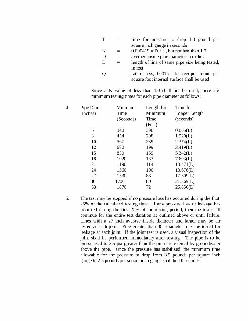
Diam. Minimum Length for Time for Time Minimum Longer Length (Seconds) Time (seconds)
(Feet) 6 340 398 0.855(L) 8 454 298 1.520(L) 10 567 239 2.374(L) 12 680 199 3.419(L) 15 850 159 5.342(L) 18 1020 133 7.693(L) 21 1190 114 10.471(L) 24 1360 100 13.676(L) 27 1530 88 17.309(L) 30 1700 80 21.369(L) 33 1870 72 25.856(L)
T = time for pressure to drop 1.0 pound per square inch gauge in seconds K = 0.000419 × D × L, but not less than 1.0 D = average inside pipe diameter in inches L = length of line of same pipe size being tested, in feet Q = rate of loss, 0.0015 cubic feet per minute per square foot internal surface shall be used
Since a K value of less than 1.0 shall not be used, there are minimum testing times for each pipe diameter as follows:
4. Pipe
(Inches)
5. The test may be stopped if no pressure loss has occurred during the first 25% of the calculated testing time. If any pressure loss or leakage has occurred during the first 25% of the testing period, then the test shall continue for the entire test duration as outlined above or until failure. Lines with a 27 inch average inside diameter and larger may be air tested at each joint. Pipe greater than 36” diameter must be tested for leakage at each joint. If the joint test is used, a visual inspection of the joint shall be performed immediately after testing. The pipe is to be pressurized to 3.5 psi greater than the pressure exerted by groundwater above the pipe. Once the pressure has stabilized, the minimum time allowable for the pressure to drop from 3.5 pounds per square inch gauge to 2.5 pounds per square inch gauge shall be 10 seconds.
6. Deflection Testing: Deflection tests shall be performed on all flexible pipes. For pipelines with inside diameters less than 27 inches, a rigid mandrel shall be used to measure deflection. For pipelines with an inside diameter 27” and greater, a method approved by the executive director shall be used to test for vertical deflections. Other methods shall provide a precision of ± two tenths of one percent (0.2 %) deflection. The test shall be conducted after the final backfill has been in place at least 30 days. No pipe shall exceed a deflection of five percent. If a pipe should fail to pass the deflection test, the problem shall be corrected and a second test shall be conducted after the final backfill has been in place an additional 30 days. The tests shall be performed without mechanical pulling devices. The design engineer should recognize that this is a maximum deflection criterion for all pipes and a deflection test less than five percent may be more appropriate for specific types and sizes of pipe. Upon completion of construction, the design engineer or other Texas Registered Professional Engineer appointed by the owner shall certify, to the Executive Director, that the entire installation has passed the deflection test. This certification shall be provided for the City to consider the requirements have been met.
7. Mandrel Sizing: The rigid mandrel shall have an outside diameter (O.D.) equal to 95% of the inside diameter (I.D) of the pipe. The inside diameter of the pipe, for the purpose of determining the outside diameter of the mandrel, shall be the average outside diameter minus two minimum wall thicknesses for O.D. controlled pipe and the average inside diameter for I.D. controlled pipe, all dimensions shall be per appropriate standard. Statistical or other "tolerance packages" shall not be considered in mandrel sizing.
8. Mandrel Design: The rigid mandrel shall be constructed of a metal or a rigid plastic material that can withstand 200 psi without being deformed. The mandrel shall have nine or more "runners" or "legs" as long as the total number of legs is an odd number. The barrel section of the mandrel shall have a length of at least 75% of the inside diameter of the pipe. A proving ring shall be provided & used for each size mandrel in use.
9. Method Options: Adjustable or flexible mandrels are prohibited. A television inspection is not a substitute for the deflection test. A deflectometer may be approved for use on a case by case basis. Mandrels with removable legs or runners may be accepted on a case by case basis.
ITEM NO. 1020 WATER MAIN BREAKS LEAK REPAIRS
1020.1 DESCRIPTION: This item shall consist of Water Main Breaks and Leak Repairs
(Water Mains, repair clamps of various types and sizes) installed in accordance with these specifications and as directed by the Engineer.
1020.2 MATERIALS: The materials for a water main breaks/leak repair shall conform
to the specifications contained within the latest revision of Material Specifications contained herein.
1020.3 CONSTRUCTION: If during the period of construction certain water facility
breaks and/or leaks in the existing distribution system occur within or immediately adjacent to the Contractor’s specified area of construction operations, the City of Cibolo Construction Inspector may authorize the replacement and/or repair to be performed by the Contractor under the bid item 1020. the work involved shall consist of excavation, hauling of disposition material, dewatering, shut-down and isolation of the existing main if required, installation of the necessary repair clamps and or new water main (length to be determined by City of Cibolo Construction Inspector) to include all necessary tie-ins, fittings, approved reaction blocking required, backfilling the excavation with approved materials; customer notification or service interruption where required. Cutting and replacing pavements (any type), curbs, sidewalks, trench protection, and sodding will be considered subsidiary to the work.
ITEM NO. 1100 SLIP-LINING SANITARY SEWERS
1100.1 DESCRIPTION: Slip-lining is accomplished by pulling or pushing liner pipe into
existing sewers by use of mechanical or hydraulic equipment. Once in place, liner pipe is allowed time to normalize and is then cut to fit between manholes. Annular spaces between liners and existing sewers are sealed at each manhole. Manhole inverts and benches are reworked and reshaped. Existing sewers remain in operation during slip-lining process, with sewage flow diverted around operations in progress.
1100.2 MATERIALS
1. Manufactures:
A. Liner pipe systems shall be fiberglass reinforced plastic (FRP) or T-
Lock Liner concrete pipe, as approved by the SAWS.
B. Acceptable manufacturer for FRP liner pipe: Shall conform with the current Standard Material Specifications accepted by SAWS.
C. Acceptable manufacturer for Amer-Plate T-Lock pipe: Ameron
Protective Linings.
2. FRP Liner Pipe and Fittings:
A. Pipe, joints and fittings: ASTM D 3262, Type 1, Liner 2, Grade 3.
B. FRP Liner Pipe: Reinforced plastic mortar pipe manufactured by centrifugal casting process resulting in dense, nonporous, corrosion- resistant, consistent, composite structure. Minimum stiffness: 72 psi, measured in accordance to ASTM D 2412. Use with a stiffness of 72 psi where specified or shown on the Drawings.
C. Resin Systems: Thermosetting polyester epoxy resin, with or without
filler, meeting ASTM D 3262.
D. Reinforcing Glass Fibers: Commercial grade E-type glass filaments, with binder and sizing compatible with impregnating resins.
E. Filler: Sand with at least 98% silica content, and maximum moisture
content of 0.2%.
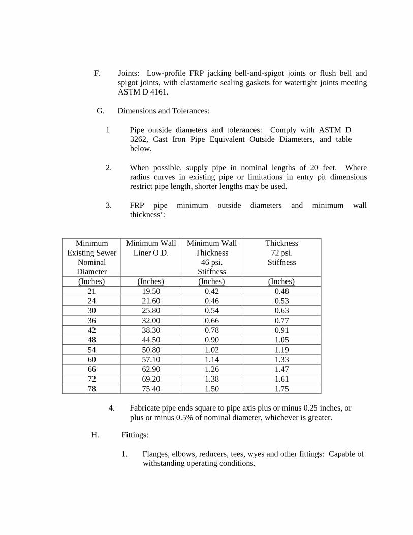
F. Joints: Low-profile FRP jacking bell-and-spigot joints or flush bell and
spigot joints, with elastomeric sealing gaskets for watertight joints meeting ASTM D 4161.
G. Dimensions and Tolerances:
1 Pipe outside diameters and tolerances: Comply with ASTM D
3262, Cast Iron Pipe Equivalent Outside Diameters, and table below.
2. When possible, supply pipe in nominal lengths of 20 feet. Where
radius curves in existing pipe or limitations in entry pit dimensions restrict pipe length, shorter lengths may be used.
3. FRP pipe minimum outside diameters and minimum wall
thickness’:
Minimum Existing Sewer
Nominal Diameter
Minimum Wall Liner O.D.
Minimum Wall Thickness
46 psi. Stiffness
Thickness 72 psi.
Stiffness
(Inches) (Inches) (Inches) (Inches) 21 19.50 0.42 0.48 24 21.60 0.46 0.53 30 25.80 0.54 0.63 36 32.00 0.66 0.77 42 38.30 0.78 0.91 48 44.50 0.90 1.05 54 50.80 1.02 1.19 60 57.10 1.14 1.33 66 62.90 1.26 1.47 72 69.20 1.38 1.61 78 75.40 1.50 1.75
4. Fabricate pipe ends square to pipe axis plus or minus 0.25 inches, or
plus or minus 0.5% of nominal diameter, whichever is greater.
H. Fittings:
1. Flanges, elbows, reducers, tees, wyes and other fittings: Capable of withstanding operating conditions.
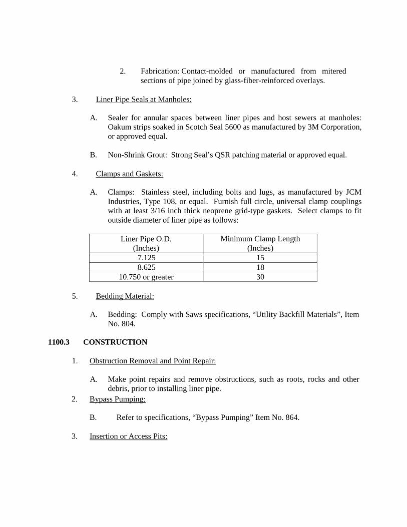
2. Fabrication: Contact-molded or manufactured from mitered sections of pipe joined by glass-fiber-reinforced overlays.
3. Liner Pipe Seals at Manholes:
A. Sealer for annular spaces between liner pipes and host sewers at manholes: Oakum strips soaked in Scotch Seal 5600 as manufactured by 3M Corporation, or approved equal.
B. Non-Shrink Grout: Strong Seal’s QSR patching material or approved equal.
4. Clamps and Gaskets:
A. Clamps: Stainless steel, including bolts and lugs, as manufactured by JCM
Industries, Type 108, or equal. Furnish full circle, universal clamp couplings with at least 3/16 inch thick neoprene grid-type gaskets. Select clamps to fit outside diameter of liner pipe as follows:
Liner Pipe O.D.
(Inches) Minimum Clamp Length
(Inches) 7.125 15 8.625 18
10.750 or greater 30
5. Bedding Material:
A. Bedding: Comply with Saws specifications, “Utility Backfill Materials”, Item No. 804.
1100.3 CONSTRUCTION
1. Obstruction Removal and Point Repair:
A. Make point repairs and remove obstructions, such as roots, rocks and other debris, prior to installing liner pipe.
2. Bypass Pumping:
B. Refer to specifications, “Bypass Pumping” Item No. 864.
3. Insertion or Access Pits:
A. Locate pits so that the total number is minimized and footage of liner pipe
installed in a single pull is maximized. Where possible, use excavations at point repair locations for insertion pits.
B. Before excavating, check with various utility providers to determine locations
of utilities in or near the work area. Costs of utility repairs, temporary service and other costs arising out of damage to or interruption of utilities, resulting from operations under this Contract, shall be borne by Contractor at no additional cost to City.
C. Perform excavation and backfill in accordance with the specifications,
“Excavation and Backfill for Utilities”, Item No. 804.
D. Perform work in accordance with OSHA standards. Comply with t h e specifications, “Trench Safety System”, Item No. 550, for excavations requiring trench safety.
E. Install and operate necessary dewatering and surface water control measures.
4. FRP Liner Pipe Installation:
FRP liner pipe may be pushed or pulled into existing sewers. Insert pipes, spigot end first, with bell end trailing. Apply pushing force to pipe wall end inside bell in accordance with manufacturer's instructions. Do not apply jacking loads to end of bell. Maximum allowable joint angular deflection one degree.
5. Clamp Installation:
A. Where excavations for liner pipe insertion are made between two
manholes, cut ends of liner pipe smooth, square to pipe axis. Join liner pipes with appropriately sized stainless steel universal clamp couplings. Butt together gap between ends of liner pipe with space between ends not exceeding 2 inches.
B. Bedding: As specified in specifications Item No. 804.
6. FRP Collar/Closure:
A. Install FRP collar closure pieces in accordance with manufacturer’s
recommendations.
7. Field Quality Control:
A. After liner installation, perform the following tests:
1. Service lateral connection test: After all service laterals have been
completed for a particular sewer section, verify integrity of re- connections at points where they join liners and existing service lines by performing smoke test.
2. Refer to the specification “Air and Deflection Testing for
Sanitary Sewers”, Item No. 849, for applicable test procedures.
8. Sealing Liner in Manhole:
A. Allow liner pipe to normalize to ambient temperatures and recover from imposed stretch before cutting to fit between manholes, sealing at manholes and shaping manhole invert. Allow at least 12 hours for normalization of polyethylene.
B. Cut liner so it extends 4 inches into manholes. Make smooth, vertical cuts and
slope areas over top of exposed liner using non-shrink grout.
C. Seal annular spaces between liner and sanitary sewer main at each manhole with chemical seal and nonshrink grout. Place strips of oakum soaked in sealer in a band to form effective water-tight gasket in annular space between liner and existing pipes in manhole. Make width of the sealing band at least 12 inches, or one-half pipe diameter, whichever is greater.
D. Finish seal liner pipe to host pipe with non-shrink grout placed around
annular space from inside manhole. Apply grout in a band at least 6 inches wide. Obtain City Engineer’s approval of sealing methods, including seal chemicals and materials.
E. Use cementitious grout to form smooth transitions with reshaped inverts and
raised manhole benches to eliminate sharp edges of liner pipe, concrete benches, and channeled inverts. Build up and smooth manhole invert to match flow line of new liner.
9. Grouting Annular Space:
A. Provide grouting plan and obtain approval of grouting plan from the Ci ty Engineer before proceeding with the Work.
B. Grout annular space between the outside of liner and inside of existing
pipe for sewer pipe 18 inches in diameter and larger, in accordance with
Section 1101, Slip-lining Grout.
10. Post-Installation Video Recording:
A. Provide the C i t y Engineer with a NASSCO-(PACP) standard video, recorded in MPEG-1 format and written to DVD, showing completed work including condition of restored connections. Comply with the specifications “Air and Deflection Testing for Sanitary Sewers”, Item No. 849 and “Cleaning and Television Inspection of Sanitary Sewers”, and specifications Item No. 866 & Item No. 868.
11. Final Cleanup:
A. Upon completion of installation and testing, clean and restore project area
affected by work of this Section.
ITEM NO. 1112 PROJECT RECORD DOCUMENTS
1112.1 DESCRIPTION: Contractor shall maintain and provide the Owner with project
record documents as specified below and is considered incidental to the work performed. Daily up keep and transmittal of record drawing identifying completed work is considered incidental and not eligible for additional payment.
1. Maintenance of Documents:
A. Maintain in Contractor's field office in clean, dry, legible condition
complete sets of the following: Contract Drawings, Specifications, Addenda, approved Shop Drawings, Samples, Photographs, Change Orders, other Modifications of Contract, Test Records, Survey Data, Field Orders, and all other documents pertinent to Contractor’s Work.
B. Provide files and racks for proper storage and easy access
C. Make documents available at all times for inspection by Owner.
D. Record documents shall not be used for any other purpose and shall
not be removed from the office without Owner’s approval.
2. Recording:
A. Label each document "PROJECT RECORD" in 2 inch high printed letters.
B. Keep record documents current and updated at least weekly.
C. Do not permanently conceal any Work until required information has
been recorded.
D. Contract Drawings - Legibly mark to record actual construction including:
1. Depths of various elements of manhole foundation in relation to
datum.
2. Horizontal and vertical location of underground utilities and appurtenances referenced to permanent surface improvements.
3. Field changes of dimensions and details.
4. Changes made by Change Order or Field Order.
5. Details not on original Contract Drawings.
E. Specifications and Addenda - Legibly mark up each Section to record:
1. Manufacturer, trade name, catalog number, and supplier of each product and item of equipment actually installed.
2. Changes made by Change Order or Field Order
3. Other matters not originally specified.
F. Shop Drawings - Maintain as record documents and legibly annotate drawings to record changes made after review.
G. Record Documents are subject to review by the Owner on a monthly basis and failure to keep documents accurate may result in the Owner withholding the Contractor’s monthly payment in partial or full.
3. Record Drawings
A. Record drawings shall reflect completion of the installation of all equipment, piping, and other work by the Contractor. The drawings shall show the Work in plan and sections as required for clarity with reference dimensions and elevations for complete record drawings. The drawings shall be furnished not later than 30 days after completion of the Work and prior to final payment. If the Contractor does not furnish record drawings final payment shall be withheld.
B. The Contract Drawings may be used as a starting point in developing these drawings. Subcontractor and manufacturer drawings may be included in this drawing package. The drawing package must be fully integrated and include the necessary cross references between drawings. The drawing package shall include interconnection and termination details to equipment furnished under this Contract.
4. Submittal
A. At project completion, deliver record documents to the Owner. Place all letter-sized material in a 3 ring binder which is neatly indexed by
process and division number. Bind Contract drawings and shop
drawings in rolls of convenient size for ease of handling.
B. Accompany the submittal with a transmittal letter in duplicate containing the following:
1. Date.
2. Project title and number.
3. Contractor’s name and address.
4. Title and number of each record document.
5. Certification that each document as submitted is complete and
accurate.
6. Signature of Contractor.
ITEM NO. 1114 PRE-CONSTRUCTION VIDEOS
1114.1 DESCRIPTION: Contractor shall be responsible for the production of pre-
construction videos in NASSCO-(PACP) standard video, recorded in MPEG-1 format and written to a DVD, as provided herein. Contractor shall provide pre- construction DVD prior to commencement of the project identifying the condition of all existing surface features within the project limits. Contractor is to coordinate the video procedures with the Owner's Representative prior to commencement.
1114.2 QUALITY: All videos shall be a NASSCO-(PACP) standard video, recorded in
MPEG-1 format written to DVD, and of good quality. DVD shall include good sound quality; identification of area being videoed to include cross streets references, addresses, time and date. Each DVD shall be marked with the name and number of contract, name of Contractor, description and location of view.
1114.3 EXECUTION: Prior to beginning the project, the contractor shall submit 1 copy
of the completed DVD for the entire project prior to submission of request for mobilization for C i t y r eview. Failure to submit DVD will result in denial of any request for payment under the mobilization line item.
ITEM NO. HP HIGH PRESSURE WATER DISTRBUTION SYSTEMS
HP-1 GENERAL. The work performed for the construction of a high pressure
water distribution system, including water mains, services, fire hydrants, and all related appurtenances, shall be done in accordance with current SAWS Specifications for Water Works Construction. This Section 12 shall apply solely to the construction of high pressure water systems and shall govern when in conflict with other sections of the these Specifications for Water Works Construction.
1. High pressure systems. Each of the water distribution systems that
furnish water in Pressure Zone 9 through Pressure Zone 16 shall be designed as a high pressure system. The static water pressure in each of these Service Levels shall be not less than 35 psi nor exceed 175 psi with no fire hydrants in use.
2. Locations of high pressure levels. Geographically, the boundaries
of Pressure Zones 9 through 16 conform to the surface contour tabulation shown in Table HP-1, High Pressure Levels.
HP-2 MATERIAL AND SUPPLIES.
1. General. Construction materials and supplies shall be furnished in accordance with provisions outlined in the Material Specifications of this manual.
2. Pipe Materials. Ductile Iron, Concrete Steel Cylinder, PVC class
200 (DR14), and Steel pipe shall be used for water main construction in the high pressure Distribution System.
HP-3 TRENCH EXCAVATION
1. General. All excavation shall be performed in accordance with
"Excavations, Trenching and Backfill", Item No. 804. HP-4 PIPE LAYING.
1. General. Pipe installation shall be performed in accordance with
"Water Main Installation", Item No. 812.
HP-5 SETTING VALVES, FITTINGS, AND FIRE HYDRANTS.
1. General. Valves, fittings, fire hydrants, plugs, and caps shall be set in accordance with Items No. 826, 830, 832, and 836 of these Specifications.
2. Valves. All valves shall be supported on a concrete pad in accordance with Standard Drawings DD-828-01, 828-02, and 828-03.
3. Fire Hydrants. All fittings for fire hydrant installations such as ties, bends, nipples, valves, and hydrants shall have anchored or flange type joints. The bowl of each hydrant and valve shall rest on a concrete pad as shown on Standard Drawing DD-834-01. The main line fire hydrant tee shall be an anchored tee properly blocked.
4. Thrust Blocking. All thrust blocking placed in conjunction with mains and appurtenances constructed in Service Levels 9 through 16 shall be in accordance with Standard Drawings DD-839-01 and DD-839-02. In all cases, the design of thrust blocking shall be of sufficient size to withstand a soil pressure of 3,000 psi unless specified otherwise in the job plans or specifications. The maximum soil pressure value that will be allowed for the design of thrust blocking shall be 5,000 psi. When soil pressure bearing values of 4,000 psi or 5,000 psi are recorded for design of thrust blocks, copies of soil test made for determining the bearing value of the soil in question shall be submitted to the Engineer for verification.
HP-6 TRENCH BACKFILL.
1. General. All backfill material shall be placed in accordance with "Excavation, Trenching, and Backfill", Item No. 804, of these specifications.
HP-7 CLEANUP.
1. General. Cleanup of the area of the construction operations shall be in accordance with these specifications.
HP-8 FLUSHING AND TESTING MAINS.
1. General. All flushing & hydrostatic testing shall be conducted in accordance with "Hydrostatic Testing Operations", Item No. 841, of these specs, except that the maximum test pressure is established at 200 psi.
HP-9 DISINFECTION OF NEW MAINS UTILIZING MACHINE CHLORINATION.
1. General. Disinfection of new mains by machine chlorination shall be accomplished in accordance with "Disinfection", Item No. 847, of these specifications.
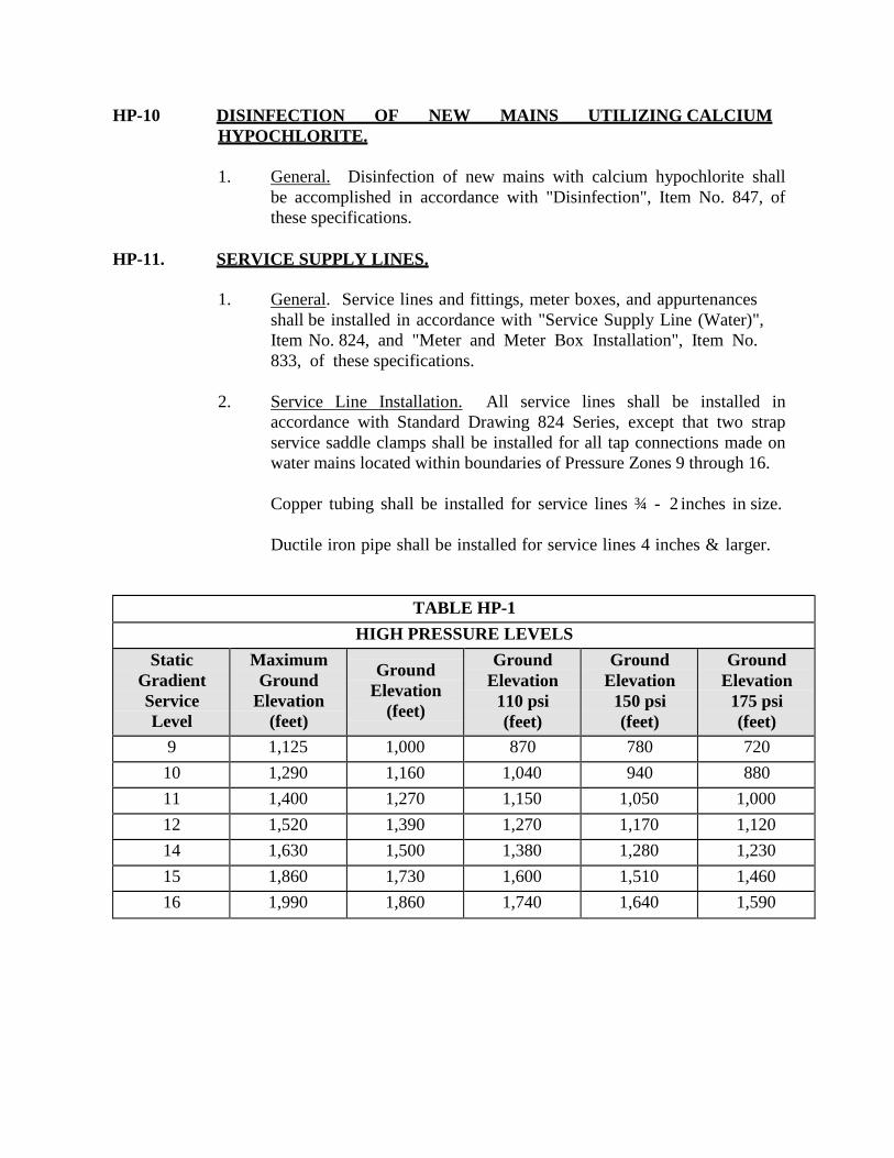
HP-10 DISINFECTION OF NEW MAINS UTILIZING CALCIUM HYPOCHLORITE.
1. General. Disinfection of new mains with calcium hypochlorite shall be accomplished in accordance with "Disinfection", Item No. 847, of these specifications.
HP-11. SERVICE SUPPLY LINES.
1. General. Service lines and fittings, meter boxes, and appurtenances shall be installed in accordance with "Service Supply Line (Water)", Item No. 824, and "Meter and Meter Box Installation", Item No. 833, of these specifications.
2. Service Line Installation. All service lines shall be installed in accordance with Standard Drawing 824 Series, except that two strap service saddle clamps shall be installed for all tap connections made on water mains located within boundaries of Pressure Zones 9 through 16.
Copper tubing shall be installed for service lines ¾ - 2 inches in size.
Ductile iron pipe shall be installed for service lines 4 inches & larger.
TABLE HP-1
HIGH PRESSURE LEVELS Static
Gradient Service Level
Maximum Ground
Elevation (feet)
Ground Elevation
(feet)
Ground Elevation
110 psi (feet)
Ground Elevation
150 psi (feet)
Ground Elevation
175 psi (feet)
9 1,125 1,000 870 780 720 10 1,290 1,160 1,040 940 880 11 1,400 1,270 1,150 1,050 1,000 12 1,520 1,390 1,270 1,170 1,120 14 1,630 1,500 1,380 1,280 1,230 15 1,860 1,730 1,600 1,510 1,460 16 1,990 1,860 1,740 1,640 1,590