Embed Size (px)
DESCRIPTION
Â
Citation preview

Studio Air
Part B: Criteria Design
Chun Yan_634071

A structure is loosely defined as a physical object, or a system therof, that enables people crossing voids, lift goods, define space etc. It's purpose of function is to supply the strength, stiffness, and ragidity to fullfill the aforementionaed functions. In my opinion, structure is a general term. Everthing is built based on a structure form, and every existent form could be a kind of structure.
I chose structure as my design brief because I think it has the most opportunities and potentials. Geometry, section biomimicry and even tesselation are formed based on their unique structure.
I am planning to buiild a changeable and flexible project based on the idea of structure. Normally, structure gives people a sense of regular, rigid and expressive, which are mostly demonstrated as lattice, waffle and column grids.
Figure 1: Parametric structure design project.

B.1 Rearch Field
A structure is loosely defined as a physical object, or a system therof, that enables people crossing voids, lift goods, define space etc. It's purpose of function is to supply the strength, stiffness, and ragidity to fullfill the aforementionaed functions. In my opinion, structure is a general term. Everthing is built based on a structure form, and every existent form could be a kind of structure.
I chose structure as my design brief because I think it has the most opportunities and potentials. Geometry, section biomimicry and even tesselation are formed based on their unique structure.
I am planning to buiild a changeable and flexible project based on the idea of structure. Normally, structure gives people a sense of regular, rigid and expressive, which are mostly demonstrated as lattice, waffle and column grids.
Figure 1: Parametric structure design project.
Case Study 1-1

The canopy is constructed of vertical laminated wood plates following a 1.5 by 1.5 cutting pattern. The assembled plates thus form a grid structure, a grillage. For safety reasons the restaurant is situated on a composite steel platform. The wood plates have been sprayed with a polyurethane coating and painted in an ivory white shade which visually brings the individual pieces together. It also results in the peculiar effect that the structure appears simultaneously as a built in-scale construction as well as an over-size model. This ambiguity between form, image, and structure is further emphasized by the fact that the construction has not been covered but is laid bare; this accentuates the contrast between the repetitious pattern of the grid and the winding shape of the canopy.
The structure forms a new gathering point in Seville: A place for interaction, in which ancient is connected with present, earth with sky. The grid structure, extensively used by the Romans for urban layouts, is here transformed and contrasted by the curving shapes of the canopy. Further movement is suggested between points, lines, and surfaces: From the nodes formed by the 'trunks' to the meandering outline of the canopy to the imaginary surfaces created by the grillage. A play between what is revealed and what is not, between virtual and actual.

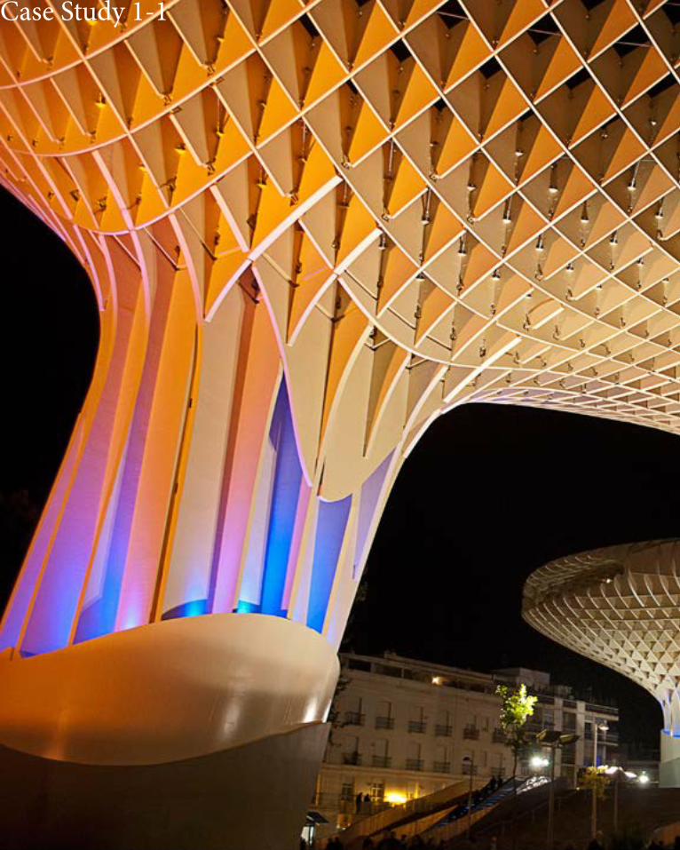
The Stadium is a massive and an incredibly complicated structure. The structural design was introduced by the Herzog & De Meuron, whom from very initial stages have been working with structural engineers from Ove Arup & Partners and developing 3D models.
Because the proposed structure was so complicated, in order to sell the idea even the smaller detail had to be thought of and modeled in the very early stages of the project.
The detail above shows one f numerous connections involved in the structure. Due to such significant loads on the structure members as well as their connections had to be designed carefully. the welding process alone sometimes took 17 hours per connection with several welders switching places to avoid exhaustion.
Developing structural calculations for this building would be incredibly rewarding and fun, but it would also be very challenging. even though computer software can be used, some hand calculations should be done to verify the results. below is a partial structural plan of roof framing for the stadium indicating the grid used to determine the geometry of the “Nest”.
Figure 2: The structure of the bird nest stadium.
Case Study 1-2
National statiumBeijingBird Nestenormous saddle-shaped elliptic steel structure
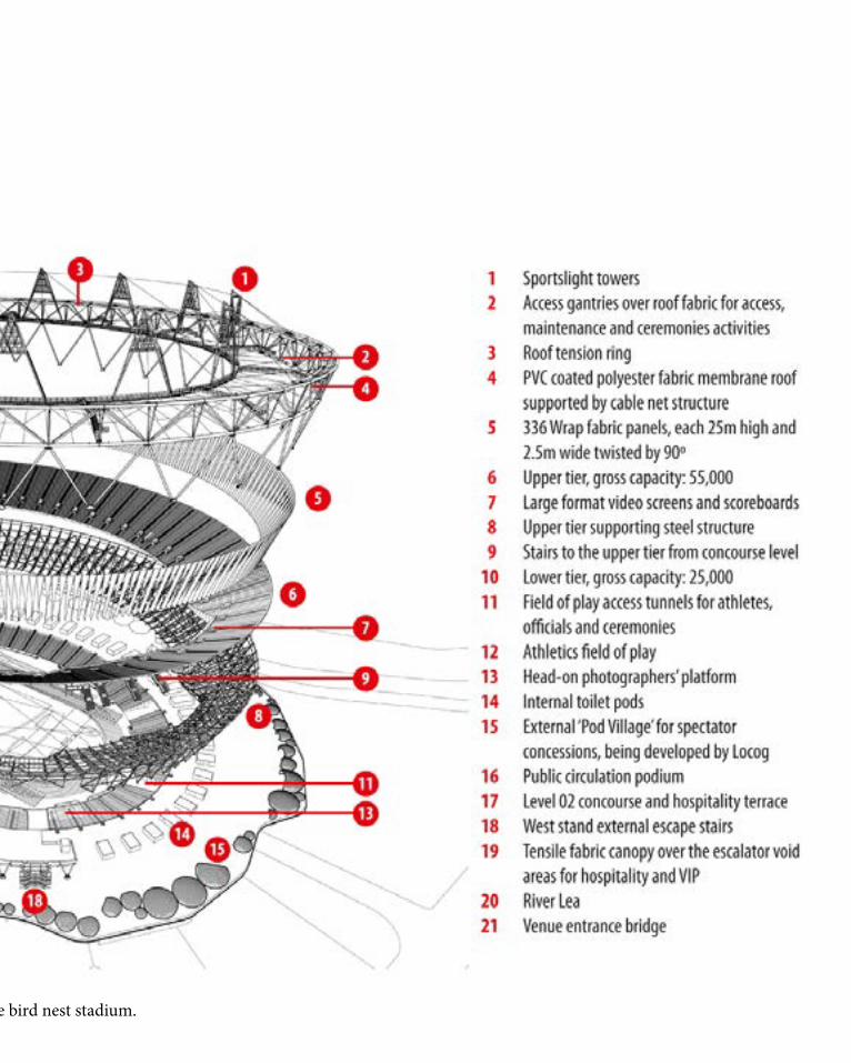
Figure 2: The structure of the bird nest stadium.

In Case Study 1.0, I used lunchbox to generate the transformation matrix throughout lunchbox plugin. The original shape of these 30 transformations is just a simple square. The main purposes that I planned to achieve and test during the process is I want to create different structure pattern firstly in 2D perspectives which can bring me a inspiration of the material that can be used to create a structure form. Sometimes, the structure is built based on the material. For example, bricks and reinforcing steel generate differet type of structure which need different force analysis. Another purpose is that i want to test the availability of different structure form. During the process that i tried to create structure pattherns i see some structure frame look stable and are valuable to do a further development. However, some of them are not a successful structure because they even didn't have connections with each other. In these 30 structural frames and patterns transformations, some of them are created by line, some of them are created by slides and some of them are created by surfaces. I imagine these as steel columns, wood chip and metal sheet. Some of them looks feasiible but some are not. I chose some of them to make a prototype to test its availability.

B.2 Case Study 1.0
In Case Study 1.0, I used lunchbox to generate the transformation matrix throughout lunchbox plugin. The original shape of these 30 transformations is just a simple square. The main purposes that I planned to achieve and test during the process is I want to create different structure pattern firstly in 2D perspectives which can bring me a inspiration of the material that can be used to create a structure form. Sometimes, the structure is built based on the material. For example, bricks and reinforcing steel generate differet type of structure which need different force analysis. Another purpose is that i want to test the availability of different structure form. During the process that i tried to create structure pattherns i see some structure frame look stable and are valuable to do a further development. However, some of them are not a successful structure because they even didn't have connections with each other. In these 30 structural frames and patterns transformations, some of them are created by line, some of them are created by slides and some of them are created by surfaces. I imagine these as steel columns, wood chip and metal sheet. Some of them looks feasiible but some are not. I chose some of them to make a prototype to test its availability.


These series are generated throughout lunchbox and then use offset or pipes to make the structure patterns 3D dimentional. Some layout which is shown in these structure is used extensively in the normal construction such as brick wall, the layout of tiles and the roof structure.


These are the structure frames I created. Some of these structure idea or form are used in the existent architecture. For example, the structural pattern on the above is normally used as a honeycomb briquet type roof structure which are built in a theatre or a music hall to reduce noise and echo. I tried to create as many structural pattern as i can, then choose appropriate material for them to build a real structure form that can be used in a part of a project.

Load ResistanceThe Beijing National Stadium is designed to resist both typical building loads and earthquake loads.
Horizontal Loads
The structure must resist a total of 56,625 tons of vertical load. The Steel structure itself must resist its own load of 42,000 tons and 11,625 tons of live load, totaling in 53,625 tons. The Plinth type of the foundation is essential to carry such a load, which is fairily evenly distributed.
Each member of the steel “Nest” is designed carefully to carry its own weight of 42, 000 tons loads. The overall shape appears to be random, but in reality it follows strict geometric rules. Figure 3; The loads at each intersection of Beijing National Statium.
The loads at each intersection are split between the members and transferred downward as indicated above.
The red points indicate the transfer connections were load impact is felt most significantly. The below image identifies the primary and secondary members. the secondary members had to be welded on two sides of primary members. The steel envelope is constructed of 22.5 miles of steel and it took about 700 welders to complete the task.
B.3 Case Study 2.0National statiumBeijingBird Nestenormous saddle-shaped elliptic steel structure

Lateral Loads
The massive steel structure resists lateral loads in a similar manner as the horizontal ones. In addition, instead of the loads hitting the structure and following it downwards and upwards it is broken down through the lattice of steel while being weakened and providing natural ventilation in the building.
The core portion of the building carries the dead load of the concrete structure as well as the live load of people totaling to 13,122 tons. The load is transferred directly to the plinth foundation as distributed load as shown on the left.
Earthquake Loads
The Beijing National Stadium was designed with earthquake loads in mind, because Beijing is prone to seismic events. The outer steel structure is completely separate from the inner stadium seating area and is placed 50 feet apart. this placement allows the two structures move independently in case of an earthquake. Steel has a rather high modulus of elasticity as compared to the concrete, therefore the entire outer structure could be put together as a unit and withstand earthquakes. The core of the stadium was constructed out of the pre-cast reinforced concrete. Because concrete has significantly lower modulus of elasticity, it was decided into eight individual sections. this division allows each portion of structure to move independently of the other in case of seismic motion causing minimal amount of damage. Beijing Bird’s Nest is designed to withstand earthquakes rated at 8.0 on Richter Scale
Figure 4; How vertical loads work at Beijing National Statium.

In Case Study 2.0, I generated the basic surface of the bird nest stadium. I want to create different structure pattern and frame and made it out as a 3D model, so that it will be easier to analyze the load, the connection and the support and resistant force in each structural form.The different achivement and test between case study 1 and 2 is that case study 1 is a 2D perspective structure while case study 2 is a 3D model transformation. The load bearing is essential to be considered. So in the 50 transformations in case study 2, I expected analyze and test the different force direction in different structure form. After create these 3D perspective transformations, I planned to choose some typical model of them to make them out throughout appropriate material.

In Case Study 2.0, I generated the basic surface of the bird nest stadium. I want to create different structure pattern and frame and made it out as a 3D model, so that it will be easier to analyze the load, the connection and the support and resistant force in each structural form.The different achivement and test between case study 1 and 2 is that case study 1 is a 2D perspective structure while case study 2 is a 3D model transformation. The load bearing is essential to be considered. So in the 50 transformations in case study 2, I expected analyze and test the different force direction in different structure form. After create these 3D perspective transformations, I planned to choose some typical model of them to make them out throughout appropriate material.
B.4 Technique development

Start by defining a central points inGH. Then generate the
Steps


There are many types of structure that are used in architecture.1)Rock and Stone2) Wood Frame3) Steel Truss and Frame4) Precast Concrete5) Reinforced Concrete6) Prestressed ConcreteThe type of system used depends on the building's needs. The height of the building, its load bearing capacity, the soil specifications and the building materials all dictate the proper structural system needed for a building. In particular, structural systems have evolved to focus on building up as undeveloped land has become scarce.Also, there are many types of structural elements as wellStructural System Elementsa) Beam and Columnb) Framec) Trussd) Arche) Wall and Platef) Cylindrical Shell and Vaultg) Spherical Shell and Domeh) Cable and Rodi)Membrane Tent and Net
In my opinion, it is impossible to show or understand a structure just throughout the trasnformation matrix. Structure is completed and developed only by analysis of the load bearing and test. Therefore, what I was trying to do in this part, is to create as changeable as structural type frame or patthern which are demonstrated in lines, pipes, surfaces, and even just connections. Then , these transformations brought me inspirations to build a structure form in different materials, which was decided by how the structural frame looks like. I combined some ideas from my transformation with sectioning, which is my group member jingjing's design criteria. At the end of Part B, we did some structure and landscape test throughtout our prototypes.


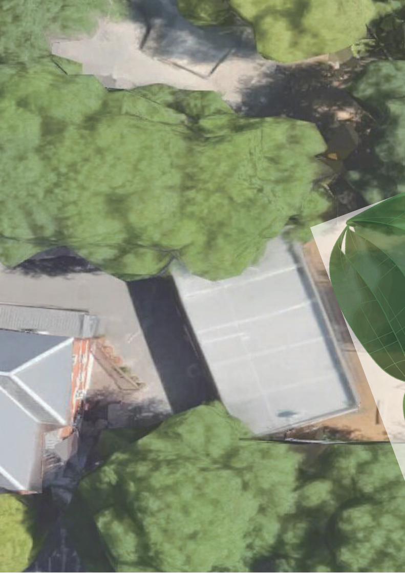
SITE ANALYSIS
We chose a flat space near the merri creek primary school as our site location. This area has extravagant vegetation. We planned to create a project which can collect fallen leaves and plants. These space has a lot of withering plants which need to be cleanning. Our design purpose is to make a good use of these withering plants and reduce the pressure of cleanning.

Site Location:Merri Creek Primary School
We chose a flat space near the merri creek primary school as our site location. This area has extravagant vegetation. We planned to create a project which can collect fallen leaves and plants. These space has a lot of withering plants which need to be cleanning. Our design purpose is to make a good use of these withering plants and reduce the pressure of cleanning.

Design Inspiration
Our original inspiration comes from the shape of the leaf. The leaf appears the most in the site. Also, leaf is a part of our design brief. We were thinking about combine this shape with our design criteria, structure and section.
Design opportunity:During the site visit we discovered that the primary school student, especially children in the early age want to get in touch with the plants along the river. However their behaviour may destory the nature and the education from school are not allow them to do that. Therefore, our design will give the opptunity to get in touch with the nature.
The purpose of the designto allow chirldren to get in touch with the nature and also provide a place for the climbers (plants) growing


Prototype 1:String connection
This prototype was inspired by the cable bridge. The main forces in a cable-stayed bridge of any type are tension in the cables and compression in the pillars. Since almost all the force on the pillars is vertically downwards and they are also stabilized by the main cables, the pillars can be made quite slender, as on the Severn Bridge, on the Wales-England border.
The purpose and achievement of this prototype is to test how tension structure , string connection and steel material work together.


Prototype 2:Waffle connection This prototype was inspired by the strucuture of Metropol Parasol. Metropol’s interweaving waffle-like wooden panels rise from concrete base reinforced with steel, which are positioned in such a way to architecturally form canopies and walkways below the parasols.

This prototype was inspired by the strucuture of Metropol Parasol. Metropol’s interweaving waffle-like wooden panels rise from concrete base reinforced with steel, which are positioned in such a way to architecturally form canopies and walkways below the parasols.

Prototype 3: Brick Structure
The ancient builders no doubt gave a great deal of thought to how they could utilize the great strength of stone and brick in compression without having to be limited by its very small strength in tension. The arch is a satisfactory solution to this prob lem, but before the true arch came into existence it was probably preceded by preliminary intuitive attempts as depicted in Fig. 4.2

The ancient builders no doubt gave a great deal of thought to how they could utilize the great strength of stone and brick in compression without having to be limited by its very small strength in tension. The arch is a satisfactory solution to this prob lem, but before the true arch came into existence it was probably preceded by preliminary intuitive attempts as depicted in Fig. 4.2

Prototype 4
This prototype came from the combination of the idea of sectioning and structure. It tested the verticle load and appearence of the design. In this stage, we tried a different structure of vertical 'overlap-type structure design.
This prototype came from the combination of the idea of sectioning and structure. It tested the verticle load and appearence of the design. In this stage, we tried a different structure of vertical 'overlap-type structure design.