Embed Size (px)
Citation preview
NXP SemiconductorsChip Errata
© 2018-2020 NXP B.V.
This document details the silicon errata known at the time of publication for the i.MX RT1060 crossover processors.Table 1 provides a revision history for this document.
,
Table 1. Document Revision History
Rev. Number Date Substantive Changes
Rev. 1.1 02/2020 • Added following errata:– ERR050235
Rev. 1 06/2019 • Added following errata:– ERR011572– ERR050101– ERR050130– ERR050144– ERR050194
Rev. 0 08/2018 • Initial version
Document Number: IMXRT1060CERev. 1.1, 02/2020
Chip Errata for the i.MX RT1060
Chip Errata for the i.MX RT1060, Rev. 1.1
2 NXP Semiconductors
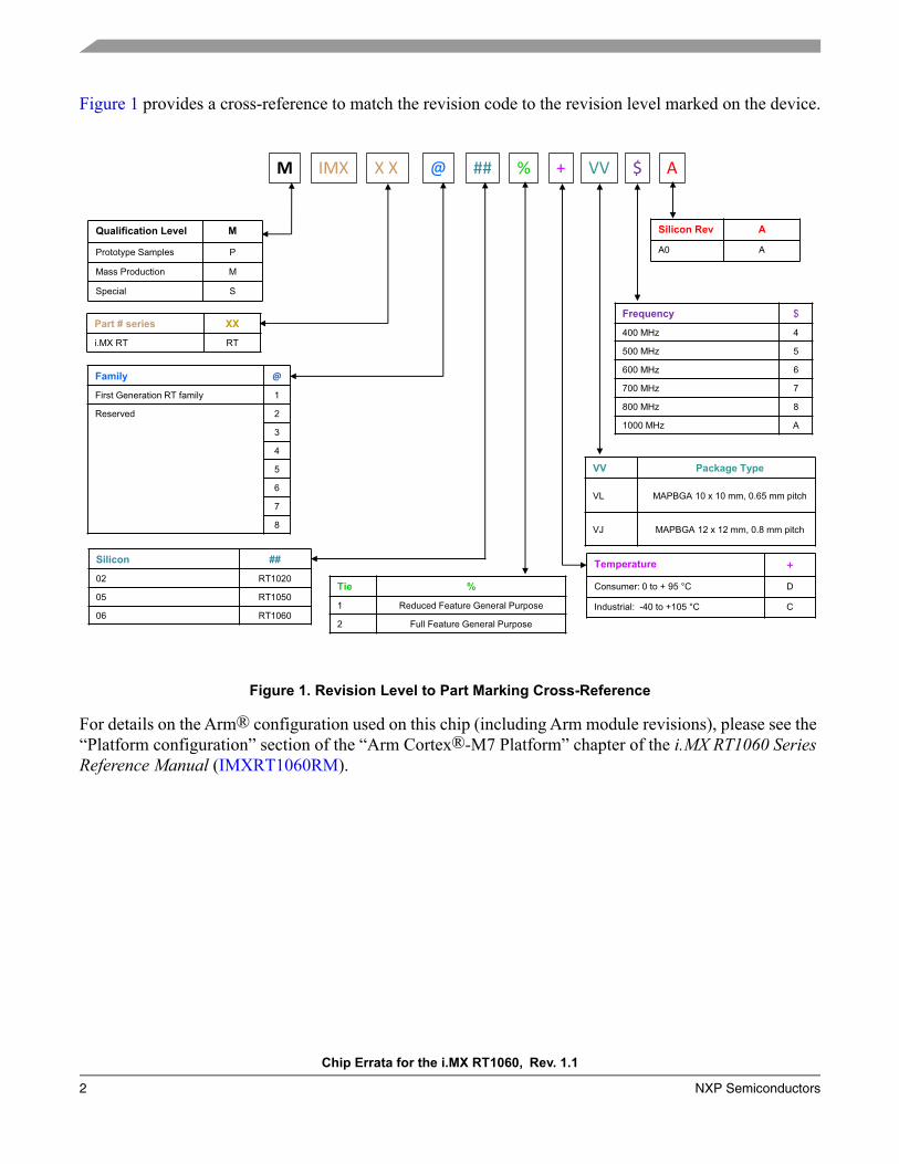
Figure 1 provides a cross-reference to match the revision code to the revision level marked on the device.
Figure 1. Revision Level to Part Marking Cross-Reference
For details on the Arm® configuration used on this chip (including Arm module revisions), please see the “Platform configuration” section of the “Arm Cortex®-M7 Platform” chapter of the i.MX RT1060 Series Reference Manual (IMXRT1060RM).
Temperature +Consumer: 0 to + 95 °C D
Industrial: -40 to +105 °C C
Frequency $
400 MHz 4
500 MHz 5
600 MHz 6
700 MHz 7
800 MHz 8
1000 MHz A
VV Package Type
VL MAPBGA 10 x 10 mm, 0.65 mm pitch
VJ MAPBGA 12 x 12 mm, 0.8 mm pitch
Qualification Level M
Prototype Samples P
Mass Production M
Special S
Part # series XX
i.MX RT RT
Silicon Rev A
A0 A
Tie %
1 Reduced Feature General Purpose
2 Full Feature General Purpose
M IMX X X @ % + VV $ A
Family @
First Generation RT family 1
Reserved 2
3
4
5
6
7
8
##
Silicon ##
02 RT1020
05 RT1050
06 RT1060
Chip Errata for the i.MX RT1060, Rev. 1.1
NXP Semiconductors 3
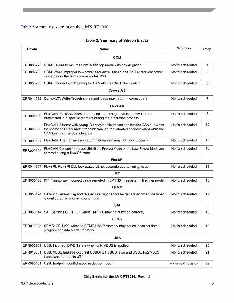
Table 2 summarizes errata on the i.MX RT1060.
Table 2. Summary of Silicon Errata
Errata Name Solution Page
CCM
ERR006223 CCM: Failure to resume from Wait/Stop mode with power gating No fix scheduled 4
ERR007265 CCM: When improper low-power sequence is used, the SoC enters low power mode before the Arm core executes WFI
No fix scheduled 5
ERR050235 CCM: Incorrect clock setting for CAN affects UART clock gating No fix scheduled 6
Cortex-M7
ERR011572 Cortex-M7: Write-Trough stores and loads may return incorrect data No fix scheduled 7
FlexCAN
ERR005829FlexCAN: FlexCAN does not transmit a message that is enabled to be transmitted in a specific moment during the arbitration process
No fix scheduled 8
ERR006032FlexCAN: A frame with wrong ID or payload is transmitted into the CAN bus when the Message Buffer under transmission is either aborted or deactivated while the CAN bus is in the Bus Idle state
No fix scheduled 10
ERR009527 FlexCAN: The transmission abort mechanism may not work properly No fix scheduled 12
ERR009595FlexCAN: Corrupt frame possible if the Freeze Mode or the Low-Power Mode are entered during a Bus-Off state
No fix scheduled 13
FlexSPI
ERR011377 FlexSPI: FlexSPI DLL lock status bit not accurate due to timing issue No fix scheduled 15
PIT
ERR050130 PIT: Temporary incorrect value reported in LMTR64H register in lifetimer mode No fix scheduled 16
QTMR
ERR050194 QTMR: Overflow flag and related interrupt cannot be generated when the timer is configured as upward count mode
No fix scheduled 17
SAI
ERR050144 SAI: Setting FCONT = 1 when TMR > 0 may not function correctly No fix scheduled 18
SEMC
ERR011225 SEMC: CPU AXI writes to SEMC NAND memory may cause incorrect data programmed into NAND memory
No fix scheduled 19
USB
ERR006281 USB: Incorrect DP/DN state when only VBUS is applied No fix scheduled 20
ERR010661 USB: VBUS leakage occurs if USBOTG1 VBUS is on and USBOTG2 VBUS transitions from on to off
No fix scheduled 21
ERR050101 USB: Endpoint conflict issue in device mode Fix in next revision 22
ERR006223
Chip Errata for the i.MX RT1060, Rev. 1.1
4 NXP Semiconductors
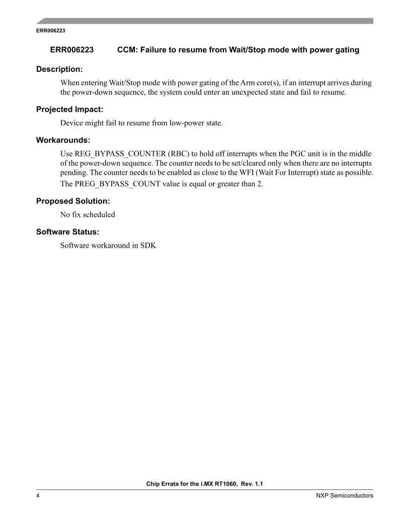
Description:
When entering Wait/Stop mode with power gating of the Arm core(s), if an interrupt arrives during the power-down sequence, the system could enter an unexpected state and fail to resume.
Projected Impact:
Device might fail to resume from low-power state.
Workarounds:
Use REG_BYPASS_COUNTER (RBC) to hold off interrupts when the PGC unit is in the middle of the power-down sequence. The counter needs to be set/cleared only when there are no interrupts pending. The counter needs to be enabled as close to the WFI (Wait For Interrupt) state as possible.The PREG_BYPASS_COUNT value is equal or greater than 2.
Proposed Solution:
No fix scheduled
Software Status:
Software workaround in SDK
ERR006223 CCM: Failure to resume from Wait/Stop mode with power gating

ERR007265
Chip Errata for the i.MX RT1060, Rev. 1.1
NXP Semiconductors 5
Description:
When software tries to enter Low-Power mode with the following sequence, the SoC enters Low-Power mode before the Arm core executes the WFI instruction:1. Set CCM_CLPCR[1:0] to 2'b00.2. Arm core enters WFI.3. Arm core wakes up from an interrupt event, which is masked by GPC or not visible to GPC,
such as an interrupt from a local timer.4. Set CCM_CLPCR[1:0] to 2'b01 or 2'b10.5. Arm core executes WFI.Before the last step, the SoC enters WAIT mode if CCM_CLPCR[1:0] is set to 2'b01, or STOP mode if CCM_CLPCR[1:0] is set to 2'b10.
Projected Impact:
This issue can lead to errors ranging from module underrun errors to system hangs depending on the specific use case.
Workarounds:
Software workaround:1. Software should trigger IRQ #41 (GPR_IRQ) to be always pending by setting
IOMUXC_GPR_GPR1_GINT.2. Software should then unmask IRQ #41 in GPC before setting CCM Low-Power mode.3. Software should mask IRQ #41 right after CCM Low-Power mode is set (set bits 0-1 of
CCM_CLPCR).
Proposed Solution:
No fix scheduled
Software Status:
Software workaround in SDK
ERR007265 CCM: When improper low-power sequence is used, the SoC enters low power mode before the Arm core executes WFI
ERR050235
Chip Errata for the i.MX RT1060, Rev. 1.1
6 NXP Semiconductors
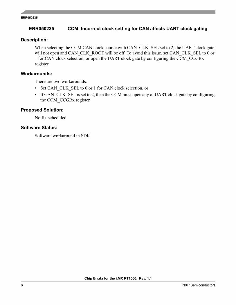
Description:
When selecting the CCM CAN clock source with CAN_CLK_SEL set to 2, the UART clock gate will not open and CAN_CLK_ROOT will be off. To avoid this issue, set CAN_CLK_SEL to 0 or 1 for CAN clock selection, or open the UART clock gate by configuring the CCM_CCGRx register.
Workarounds:
There are two workarounds:• Set CAN_CLK_SEL to 0 or 1 for CAN clock selection, or• If CAN_CLK_SEL is set to 2, then the CCM must open any of UART clock gate by configuring
the CCM_CCGRx register.
Proposed Solution:
No fix scheduled
Software Status:
Software workaround in SDK
ERR050235 CCM: Incorrect clock setting for CAN affects UART clock gating
ERR011572
Chip Errata for the i.MX RT1060, Rev. 1.1
NXP Semiconductors 7
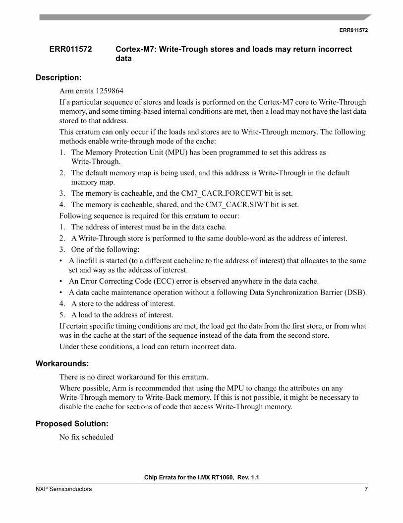
Description:
Arm errata 1259864If a particular sequence of stores and loads is performed on the Cortex-M7 core to Write-Through memory, and some timing-based internal conditions are met, then a load may not have the last data stored to that address. This erratum can only occur if the loads and stores are to Write-Through memory. The following methods enable write-through mode of the cache:1. The Memory Protection Unit (MPU) has been programmed to set this address as
Write-Through.2. The default memory map is being used, and this address is Write-Through in the default
memory map.3. The memory is cacheable, and the CM7_CACR.FORCEWT bit is set.4. The memory is cacheable, shared, and the CM7_CACR.SIWT bit is set.Following sequence is required for this erratum to occur:1. The address of interest must be in the data cache.2. A Write-Through store is performed to the same double-word as the address of interest.3. One of the following:• A linefill is started (to a different cacheline to the address of interest) that allocates to the same
set and way as the address of interest.• An Error Correcting Code (ECC) error is observed anywhere in the data cache.• A data cache maintenance operation without a following Data Synchronization Barrier (DSB).4. A store to the address of interest.5. A load to the address of interest.If certain specific timing conditions are met, the load get the data from the first store, or from what was in the cache at the start of the sequence instead of the data from the second store. Under these conditions, a load can return incorrect data.
Workarounds:
There is no direct workaround for this erratum.Where possible, Arm is recommended that using the MPU to change the attributes on any Write-Through memory to Write-Back memory. If this is not possible, it might be necessary to disable the cache for sections of code that access Write-Through memory.
Proposed Solution:
No fix scheduled
ERR011572 Cortex-M7: Write-Trough stores and loads may return incorrect data

ERR005829
Chip Errata for the i.MX RT1060, Rev. 1.1
8 NXP Semiconductors
Description:
FlexCAN does not transmit a message that is enabled to be transmitted in a specific moment during the arbitration process. The following conditions are necessary for the issue to occur:• Only one message buffer is configured to be transmitted.• The write which enables the message buffer to be transmitted (write on Control/Status word)
happens during a specific clock during the arbitration process.• After this arbitration process occurs, the bus goes to the Idle state and no new message is
received on the bus.For example:1. Message buffer 13 is deactivated on RxIntermission (write 0x0 to the CODE field from the
Control/Status word) [First write to CODE]2. Reconfigure the ID and data fields3. Enable the message buffer 13 to be transmitted on BusIdle (write 0xC on CODE field) [Second
write to CODE]4. CAN bus keeps in Idle state5. No write on the Control/Status from any message buffer happens.During the second write to CODE (step 3), the write must happen one clock before the current message buffer 13 to be scanned by arbitration process. In this case, it does not detect the new code (0xC) and no new arbitration is scheduled.The problem can be detected only if the message traffic ceases and the CAN bus enters into Idle state after the described sequence of events.There is no issue if any of the conditions below holds:• Any message buffer (either Tx or Rx) is reconfigured (by writing to its CS field) just after the
Intermission field.• There are other configured message buffers to be transmitted.• A new incoming message sent by any external node starts just after the Intermission field.
Projected Impact:
FlexCAN does not transmit a message that is enabled to be transmitted in a specific moment.
Workarounds:
To transmit a CAN frame, the CPU must prepare a message buffer for transmission by executing the following standard 5-step procedure:1. Check if the respective interrupt bit is set and clear it.
ERR005829 FlexCAN: FlexCAN does not transmit a message that is enabled to be transmitted in a specific moment during the arbitration process
ERR005829
Chip Errata for the i.MX RT1060, Rev. 1.1
NXP Semiconductors 9
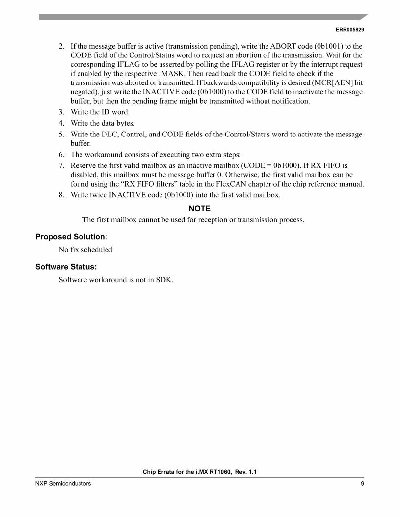
2. If the message buffer is active (transmission pending), write the ABORT code (0b1001) to the CODE field of the Control/Status word to request an abortion of the transmission. Wait for the corresponding IFLAG to be asserted by polling the IFLAG register or by the interrupt request if enabled by the respective IMASK. Then read back the CODE field to check if the transmission was aborted or transmitted. If backwards compatibility is desired (MCR[AEN] bit negated), just write the INACTIVE code (0b1000) to the CODE field to inactivate the message buffer, but then the pending frame might be transmitted without notification.
3. Write the ID word.4. Write the data bytes.5. Write the DLC, Control, and CODE fields of the Control/Status word to activate the message
buffer.6. The workaround consists of executing two extra steps:7. Reserve the first valid mailbox as an inactive mailbox (CODE = 0b1000). If RX FIFO is
disabled, this mailbox must be message buffer 0. Otherwise, the first valid mailbox can be found using the “RX FIFO filters” table in the FlexCAN chapter of the chip reference manual.
8. Write twice INACTIVE code (0b1000) into the first valid mailbox.
NOTE
The first mailbox cannot be used for reception or transmission process.
Proposed Solution:
No fix scheduled
Software Status:
Software workaround is not in SDK.
ERR006032
Chip Errata for the i.MX RT1060, Rev. 1.1
10 NXP Semiconductors
Description:
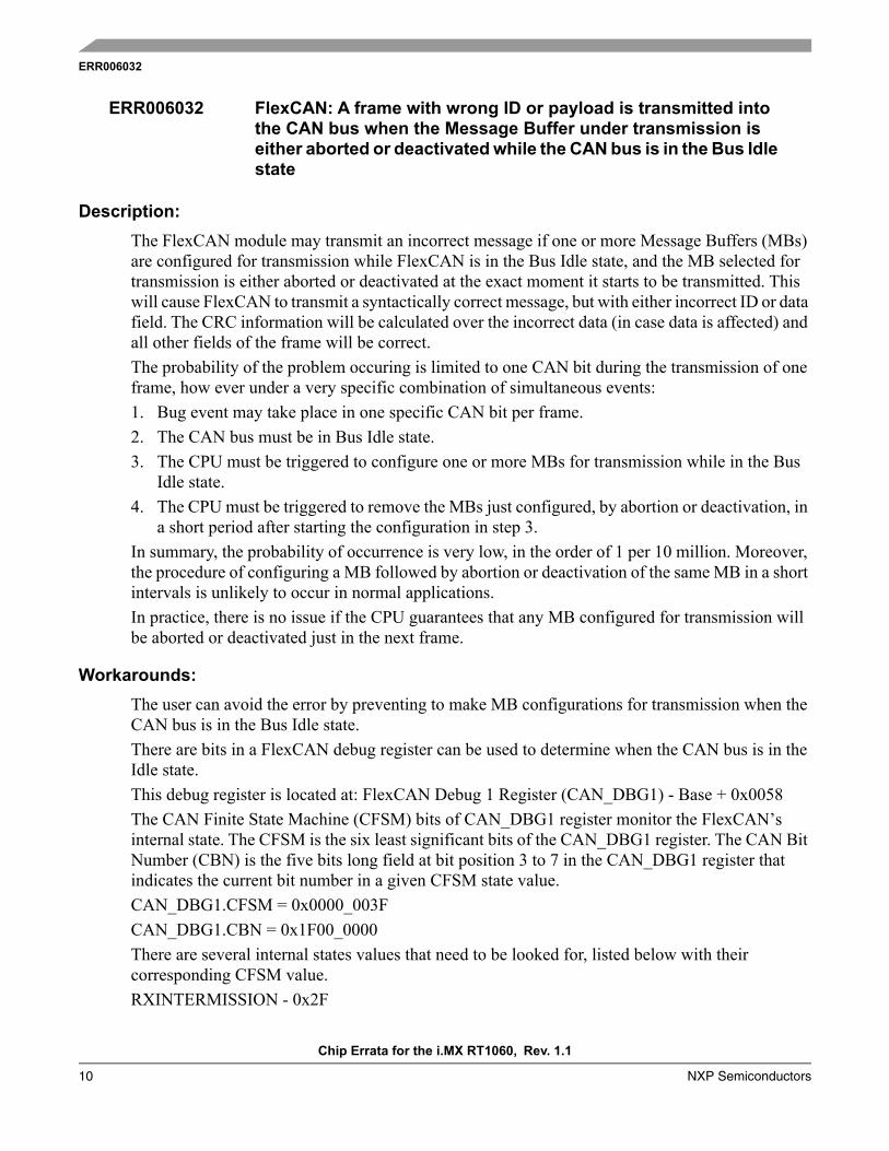
The FlexCAN module may transmit an incorrect message if one or more Message Buffers (MBs) are configured for transmission while FlexCAN is in the Bus Idle state, and the MB selected for transmission is either aborted or deactivated at the exact moment it starts to be transmitted. This will cause FlexCAN to transmit a syntactically correct message, but with either incorrect ID or data field. The CRC information will be calculated over the incorrect data (in case data is affected) and all other fields of the frame will be correct. The probability of the problem occuring is limited to one CAN bit during the transmission of one frame, how ever under a very specific combination of simultaneous events:1. Bug event may take place in one specific CAN bit per frame.2. The CAN bus must be in Bus Idle state.3. The CPU must be triggered to configure one or more MBs for transmission while in the Bus
Idle state.4. The CPU must be triggered to remove the MBs just configured, by abortion or deactivation, in
a short period after starting the configuration in step 3. In summary, the probability of occurrence is very low, in the order of 1 per 10 million. Moreover, the procedure of configuring a MB followed by abortion or deactivation of the same MB in a short intervals is unlikely to occur in normal applications.In practice, there is no issue if the CPU guarantees that any MB configured for transmission will be aborted or deactivated just in the next frame.
Workarounds:
The user can avoid the error by preventing to make MB configurations for transmission when the CAN bus is in the Bus Idle state. There are bits in a FlexCAN debug register can be used to determine when the CAN bus is in the Idle state.This debug register is located at: FlexCAN Debug 1 Register (CAN_DBG1) - Base + 0x0058The CAN Finite State Machine (CFSM) bits of CAN_DBG1 register monitor the FlexCAN’s internal state. The CFSM is the six least significant bits of the CAN_DBG1 register. The CAN Bit Number (CBN) is the five bits long field at bit position 3 to 7 in the CAN_DBG1 register that indicates the current bit number in a given CFSM state value. CAN_DBG1.CFSM = 0x0000_003FCAN_DBG1.CBN = 0x1F00_0000There are several internal states values that need to be looked for, listed below with their corresponding CFSM value.RXINTERMISSION - 0x2F
ERR006032 FlexCAN: A frame with wrong ID or payload is transmitted into the CAN bus when the Message Buffer under transmission is either aborted or deactivated while the CAN bus is in the Bus Idle state
ERR006032
Chip Errata for the i.MX RT1060, Rev. 1.1
NXP Semiconductors 11
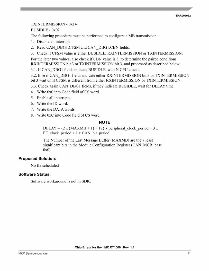
TXINTERMISSION - 0x14BUSIDLE - 0x02The following procedure must be performed to configure a MB transmission:1. Disable all interrupt2. Read CAN_DBG1.CFSM and CAN_DBG1.CBN fields.3. Check if CFSM value is either BUSIDLE, RXINTERMISSION or TXINTERMISSION.For the later two values, also check if CBN value is 3, to determine the paired conditions RXINTERMISSION bit 3 or TXINTERMISSION bit 3, and processed as described below. 3.1. If CAN_DBG1 fields indicate BUSIDLE, wait N CPU clocks.3.2. Else if CAN_DBG1 fields indicate either RXINTERMISSION bit 3 or TXINTERMISSION bit 3 wait until CFSM is different from either RXINTERMISSION or TXINTERMISSION.3.3. Check again CAN_DBG1 fields, if they indicate BUSIDLE, wait for DELAY time.4. Write 0x0 into Code field of CS word.5. Enable all interrupts.6. Write the ID word.7. Write the DATA words.8. Write 0xC into Code field of CS word.
NOTE
DELAY = {2 x (MAXMB + 1) + 18} x peripheral_clock_period + 3 x PE_clock_period + 1 x CAN_bit_period
The Number of the Last Message Buffer (MAXMB) are the 7 least significant bits in the Module Configuration Register (CAN_MCR: base + 0x0).
Proposed Solution:
No fix scheduled
Software Status:
Software workaround is not in SDK.
ERR009527
Chip Errata for the i.MX RT1060, Rev. 1.1
12 NXP Semiconductors
Description:
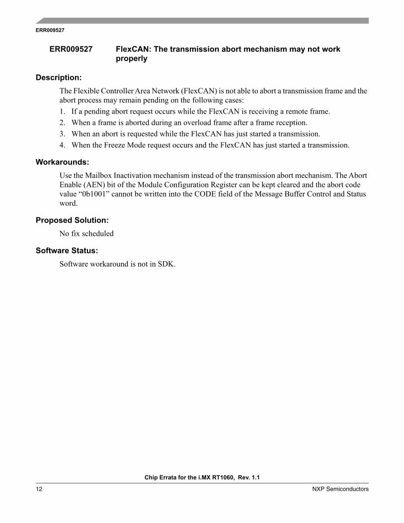
The Flexible Controller Area Network (FlexCAN) is not able to abort a transmission frame and the abort process may remain pending on the following cases:1. If a pending abort request occurs while the FlexCAN is receiving a remote frame.2. When a frame is aborted during an overload frame after a frame reception.3. When an abort is requested while the FlexCAN has just started a transmission.4. When the Freeze Mode request occurs and the FlexCAN has just started a transmission.
Workarounds:
Use the Mailbox Inactivation mechanism instead of the transmission abort mechanism. The Abort Enable (AEN) bit of the Module Configuration Register can be kept cleared and the abort code value “0b1001” cannot be written into the CODE field of the Message Buffer Control and Status word.
Proposed Solution:
No fix scheduled
Software Status:
Software workaround is not in SDK.
ERR009527 FlexCAN: The transmission abort mechanism may not work properly
ERR009595
Chip Errata for the i.MX RT1060, Rev. 1.1
NXP Semiconductors 13
Description:
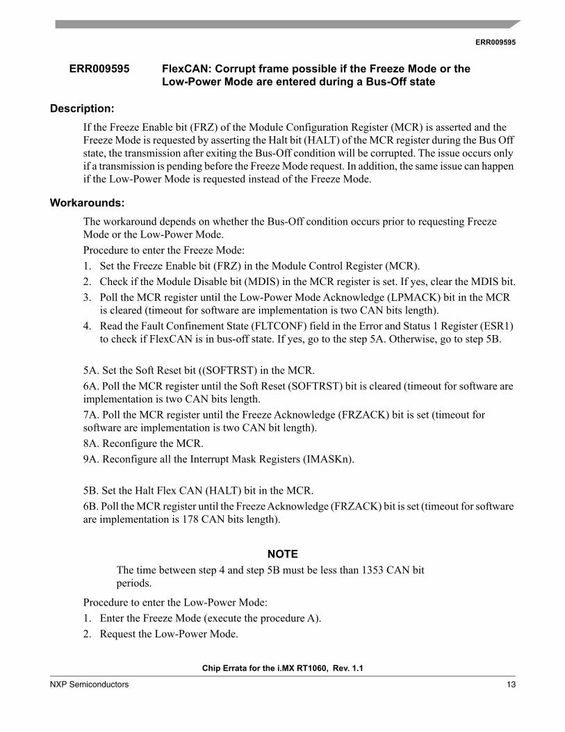
If the Freeze Enable bit (FRZ) of the Module Configuration Register (MCR) is asserted and the Freeze Mode is requested by asserting the Halt bit (HALT) of the MCR register during the Bus Off state, the transmission after exiting the Bus-Off condition will be corrupted. The issue occurs only if a transmission is pending before the Freeze Mode request. In addition, the same issue can happen if the Low-Power Mode is requested instead of the Freeze Mode.
Workarounds:
The workaround depends on whether the Bus-Off condition occurs prior to requesting Freeze Mode or the Low-Power Mode.Procedure to enter the Freeze Mode:1. Set the Freeze Enable bit (FRZ) in the Module Control Register (MCR).2. Check if the Module Disable bit (MDIS) in the MCR register is set. If yes, clear the MDIS bit.3. Poll the MCR register until the Low-Power Mode Acknowledge (LPMACK) bit in the MCR
is cleared (timeout for software are implementation is two CAN bits length).4. Read the Fault Confinement State (FLTCONF) field in the Error and Status 1 Register (ESR1)
to check if FlexCAN is in bus-off state. If yes, go to the step 5A. Otherwise, go to step 5B.
5A. Set the Soft Reset bit ((SOFTRST) in the MCR.6A. Poll the MCR register until the Soft Reset (SOFTRST) bit is cleared (timeout for software are implementation is two CAN bits length.7A. Poll the MCR register until the Freeze Acknowledge (FRZACK) bit is set (timeout for software are implementation is two CAN bit length).8A. Reconfigure the MCR.9A. Reconfigure all the Interrupt Mask Registers (IMASKn).
5B. Set the Halt Flex CAN (HALT) bit in the MCR.6B. Poll the MCR register until the Freeze Acknowledge (FRZACK) bit is set (timeout for software are implementation is 178 CAN bits length).
NOTE
The time between step 4 and step 5B must be less than 1353 CAN bit periods.
Procedure to enter the Low-Power Mode:1. Enter the Freeze Mode (execute the procedure A).2. Request the Low-Power Mode.
ERR009595 FlexCAN: Corrupt frame possible if the Freeze Mode or the Low-Power Mode are entered during a Bus-Off state

ERR009595
Chip Errata for the i.MX RT1060, Rev. 1.1
14 NXP Semiconductors
3. Poll the MCR register until the Low-Power Mode Acknowledge (LPMACK) bit in the MCR is set (timeout for software are implementation is two CAN bit length).
Proposed Solution:
No fix scheduled
Software Status:
Software workaround is not in SDK.
ERR011377
Chip Errata for the i.MX RT1060, Rev. 1.1
NXP Semiconductors 15
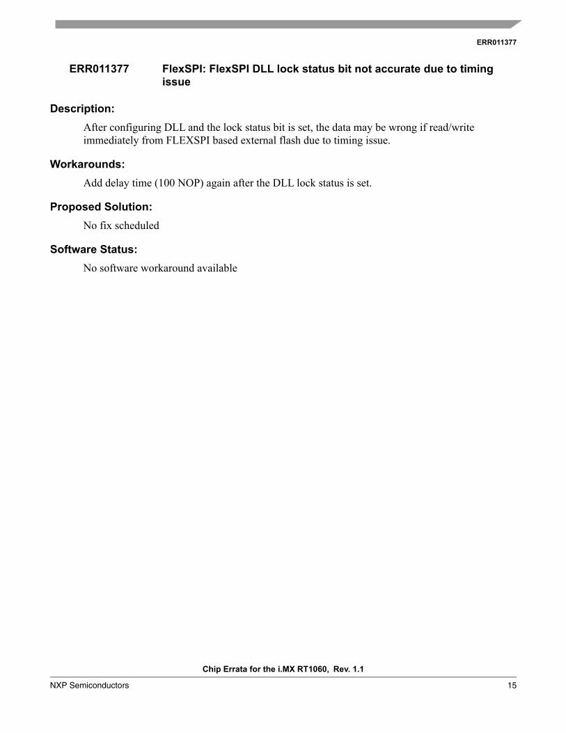
Description:
After configuring DLL and the lock status bit is set, the data may be wrong if read/write immediately from FLEXSPI based external flash due to timing issue.
Workarounds:
Add delay time (100 NOP) again after the DLL lock status is set.
Proposed Solution:
No fix scheduled
Software Status:
No software workaround available
ERR011377 FlexSPI: FlexSPI DLL lock status bit not accurate due to timing issue
ERR050130
Chip Errata for the i.MX RT1060, Rev. 1.1
16 NXP Semiconductors
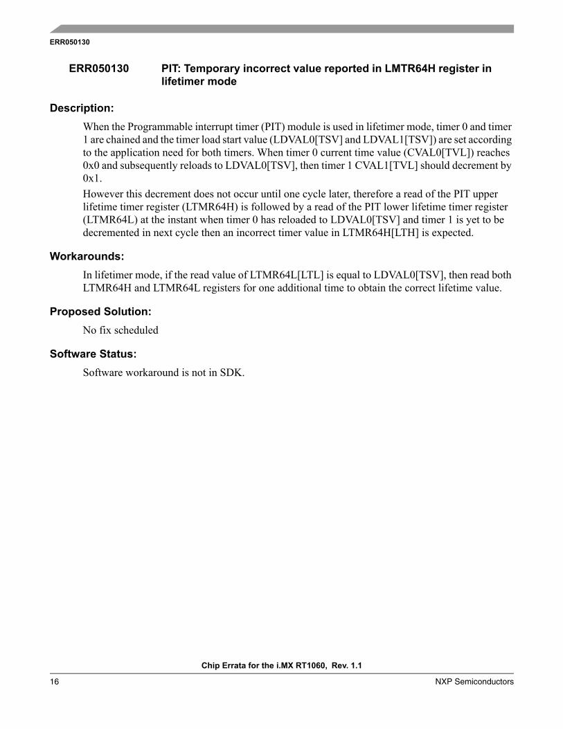
Description:
When the Programmable interrupt timer (PIT) module is used in lifetimer mode, timer 0 and timer 1 are chained and the timer load start value (LDVAL0[TSV] and LDVAL1[TSV]) are set according to the application need for both timers. When timer 0 current time value (CVAL0[TVL]) reaches 0x0 and subsequently reloads to LDVAL0[TSV], then timer 1 CVAL1[TVL] should decrement by 0x1.However this decrement does not occur until one cycle later, therefore a read of the PIT upper lifetime timer register (LTMR64H) is followed by a read of the PIT lower lifetime timer register (LTMR64L) at the instant when timer 0 has reloaded to LDVAL0[TSV] and timer 1 is yet to be decremented in next cycle then an incorrect timer value in LTMR64H[LTH] is expected.
Workarounds:
In lifetimer mode, if the read value of LTMR64L[LTL] is equal to LDVAL0[TSV], then read both LTMR64H and LTMR64L registers for one additional time to obtain the correct lifetime value.
Proposed Solution:
No fix scheduled
Software Status:
Software workaround is not in SDK.
ERR050130 PIT: Temporary incorrect value reported in LMTR64H register in lifetimer mode

ERR050194
Chip Errata for the i.MX RT1060, Rev. 1.1
NXP Semiconductors 17
Description:
1. Overflow flag and related interrupt cannot be generated successfully in upward count mode.2. When TMR_CTRL[OUTMODE] is set to 110b, OFLAG output is not cleared on counter
rollover when the timer counts upward.
Workarounds:
For item 1, using compare interrupt instead of overflow interrupt by setting compare value to 0xFFFF. The compare interrupt has the same timing effect as overflow interrupt in this way. For item 2, there is no workaround.
Proposed Solution:
No fix scheduled
Software Status:
Software workaround is not in SDK.
ERR050194 QTMR: Overflow flag and related interrupt cannot be generated when the timer is configured as upward count mode

ERR050144
Chip Errata for the i.MX RT1060, Rev. 1.1
18 NXP Semiconductors
Description:
When FCONT = 1 the transmitter will recover after a FIFO error when the FIFO is no longer empty and starting again from the same word in the following frame where the error occurred.Configuring TMR > 0 will configure one or more words in the frame to be masked (nothing transmitted during that slot). If anything other than the last word(s) in the frame are masked when FCONT = 1 and a FIFO Error Flag is set, then the transmitter will not recover and will set FIFO Error Flag during each frame.
Workarounds:
To avoid this issue, set FCONT in TCR4 to be 0.
Proposed Solution:
No fix scheduled
Software Status:
Software workaround is not in SDK.
ERR050144 SAI: Setting FCONT = 1 when TMR > 0 may not function correctly
ERR011225
Chip Errata for the i.MX RT1060, Rev. 1.1
NXP Semiconductors 19
Description:
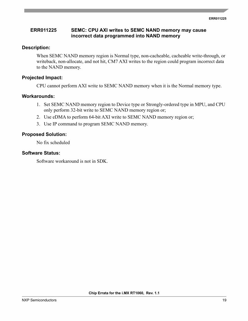
When SEMC NAND memory region is Normal type, non-cacheable, cacheable write-through, or writeback, non-allocate, and not hit, CM7 AXI writes to the region could program incorrect data to the NAND memory.
Projected Impact:
CPU cannot perform AXI write to SEMC NAND memory when it is the Normal memory type.
Workarounds:
1. Set SEMC NAND memory region to Device type or Strongly-ordered type in MPU, and CPU only perform 32-bit write to SEMC NAND memory region or;
2. Use eDMA to perform 64-bit AXI write to SEMC NAND memory region or;3. Use IP command to program SEMC NAND memory.
Proposed Solution:
No fix scheduled
Software Status:
Software workaround is not in SDK.
ERR011225 SEMC: CPU AXI writes to SEMC NAND memory may cause incorrect data programmed into NAND memory

ERR006281
Chip Errata for the i.MX RT1060, Rev. 1.1
20 NXP Semiconductors
Description:
When VBUS is applied without any other supplies, incorrect communication states are possible on the data (DP/DN) signals. If VDDHIGH_IN is supplied, the problem is removed.
Projected Impact:
This issue primarily impacts applications using charger detection to signal power modes to a PMIC in an undercharged battery scenario where the standard USB current allotment is not sufficient to boot the system.
Workarounds:
Apply VDDHIGH_IN if battery charge detection is needed. Otherwise, disable charger detection by setting the EN_B bit in USB_ANALOG_USBx_CHRG_DETECTn to 1.
Proposed Solution:
No fix scheduled
Software Status:
Software workaround is not in SDK.
ERR006281 USB: Incorrect DP/DN state when only VBUS is applied

ERR010661
Chip Errata for the i.MX RT1060, Rev. 1.1
NXP Semiconductors 21
Description:
When two USB ports work as OTG or device simultaneously. One VBUS (selected by PMU_REG_3P0.vbus_sel bit) voltage will not drop after cable unplug, causing the port to fail to detect the cable detach. If these two ports do not need to support detach detection, simultaneously using two OTGs or devices can be supported.
Conditions:
When two USB ports work as OTGs or devices simultaneously.
Projected Impact:
Do not use two OTGs or devices simultaneously. Only four scenarios are supported:• One for OTG/Device, another for Host.• One for OTG/Device, another is un-used.• One for Host, another for Host.• One for Host, another is un-used.
Workarounds:
Only one port can be used as OTG or device. The other port must be used as host. Set the PMU_REG_3P0.vbus_sel bit to select the host port.
Proposed Solution:
No fix scheduled
Software Status:
No software workaround available
ERR010661 USB: VBUS leakage occurs if USBOTG1 VBUS is on and USBOTG2 VBUS transitions from on to off
ERR050101
Chip Errata for the i.MX RT1060, Rev. 1.1
22 NXP Semiconductors
Description:
An endpoint conflict occurs when the USB is working in device mode during an isochronous communication.When the endpointA IN direction is an isochronous IN endpoint, and the host sends an IN token to endpointA on another device, then the OUT transaction may be missed regardless the OUT endpoint number. Generally, this occurs when the device is connected to the host through a hub and other devices are connected to the same hub.The affected OUT endpoint can be either control, bulk, isochronous, or an interrupt endpoint. After the OUT endpoint is primed, if an IN token to the same endpoint number on another device is received, then the OUT endpoint may be unprimed (cannot be detected by software), which causes this endpoint to no longer respond to the host OUT token, and thus, no corresponding interrupt occurs.
Workarounds:
Do not connect to a hub in case ISO IN endpoint(s) is used. When the hub(s) must be connected in this case, the endpoint number(s) of the ISO IN endpoint(s) should be different from the endpoint number(s) of any types of IN endpoint(s) used in any other device(s) connected to the same host.
Proposed Solution:
Fix in next revision
ERR050101 USB: Endpoint conflict issue in device mode

Document Number: IMXRT1060CERev. 1.102/2020
Information in this document is provided solely to enable system and software implementers
to use NXP products. There are no express or implied copyright licenses granted hereunder
to design or fabricate any integrated circuits based on the information in this document. NXP
reserves the right to make changes without further notice to any products herein.
NXP makes no warranty, representation, or guarantee regarding the suitability of its products
for any particular purpose, nor does NXP assume any liability arising out of the application
or use of any product or circuit, and specifically disclaims any and all liability, including
without limitation consequential or incidental damages. “Typical” parameters that may be
provided in NXP data sheets and/or specifications can and do vary in different applications,
and actual performance may vary over time. All operating parameters, including “typicals”
must be validated for each customer application by customer‚ customer’s technical experts.
NXP does not convey any license under its patent rights nor the rights of others. NXP sells
products pursuant to standard terms and conditions of sale, which can be found at the
following address: nxp.com/SalesTermsandConditions.
While NXP has implemented advanced security features, all products may be subject to
unidentified vulnerabilities. Customers are responsible for the design and operation of their
applications and products to reduce the effect of these vulnerabilities on customer’s
applications and products, and NXP accepts no liability for any vulnerability that is
discovered. Customers should implement appropriate design and operating safeguards to
minimize the risks associated with their applications and products.
NXP, the NXP logo, NXP SECURE CONNECTIONS FOR A SMARTER WORLD,
COOLFLUX, EMBRACE, GREENCHIP, HITAG, I2C BUS, ICODE, JCOP, LIFE VIBES,
MIFARE, MIFARE CLASSIC, MIFARE DESFire, MIFARE PLUS, MIFARE FLEX, MANTIS,
MIFARE ULTRALIGHT, MIFARE4MOBILE, MIGLO, NTAG, ROADLINK, SMARTLX,
SMARTMX, STARPLUG, TOPFET, TRENCHMOS, UCODE, Freescale, the Freescale logo,
AltiVec, C-5, CodeTEST, CodeWarrior, ColdFire, ColdFire+, C-Ware, the Energy Efficient
Solutions logo, Kinetis, Layerscape, MagniV, mobileGT, PEG, PowerQUICC, Processor
Expert, QorIQ, QorIQ Qonverge, Ready Play, SafeAssure, the SafeAssure logo, StarCore,
Symphony, VortiQa, Vybrid, Airfast, BeeKit, BeeStack, CoreNet, Flexis, MXC, Platform in a
Package, QUICC Engine, SMARTMOS, Tower, TurboLink, UMEMS, EdgeScale, EdgeLock, eIQ, and Immersive3D are trademarks of NXP B.V. All other product or service names are
the property of their respective owners. AMBA, Arm, Arm7, Arm7TDMI, Arm9, Arm11,
Artisan, big.LITTLE, Cordio, CoreLink, CoreSight, Cortex, DesignStart, DynamIQ, Jazelle,
Keil, Mali, Mbed, Mbed Enabled, NEON, POP, RealView, SecurCore, Socrates, Thumb,
TrustZone, ULINK, ULINK2, ULINK-ME, ULINK-PLUS, ULINKpro, μVision, Versatile are
trademarks or registered trademarks of Arm Limited (or its subsidiaries) in the US and/or
elsewhere. The related technology may be protected by any or all of patents, copyrights,
designs and trade secrets. All rights reserved. Oracle and Java are registered trademarks of
Oracle and/or its affiliates. The Power Architecture and Power.org word marks and the Power
and Power.org logos and related marks are trademarks and service marks licensed by
Power.org.
© 2018-2020 NXP B.V.
How to Reach Us:
Home Page: nxp.com
Web Support: nxp.com/support