Embed Size (px)
Citation preview
Linköping Studies in Science and Technology Licentiate Thesis No. 1357
Characterization of Ti2AlC Coatings Deposited with High Velocity Oxy-Fuel and Magnetron Sputtering Techniques
Jenny Frodelius
LIU-TEK-LIC-2008:15 Thin Film Physics Division
Department of Physics, Chemistry, and Biology (IFM) Linköping University
SE-581 83 Linköping, Sweden
© Jenny Frodelius 2008
ISBN: 978-91-7393-936-2 ISSN 0280-7971
Printed by LiU-Tryck, Linköping 2008

To John and my FamilyTo John and my FamilyTo John and my FamilyTo John and my Family for for for for tiretiretiretireless supportless supportless supportless support

1
Abstract
This Thesis presents two different deposition techniques for the synthesis of Ti2AlC coatings.
First, I have fabricated Ti2AlC coatings by high velocity oxy-fuel (HVOF) spraying. Analysis
with scanning electron microscopy (SEM) show dense coatings with thicknesses of ~150 µm
when spraying with a MAXTHAL 211TM Ti2AlC powder of size ~38 µm in an H2/O2 gas
flow. The films showed good adhesion to stainless steel substrates as determined by bending
tests and the hardness was 3-5 GPa. X-ray diffraction (XRD) detected minority phases of
Ti3AlC2, TiC, and AlxTiy alloys. The use of a larger powder size of 56 µm resulted in an
increased amount of cracks and delaminations in the coatings. This was explained by less
melted material, which is needed as a binding material. Second, magnetron sputtering of thin
films was performed with a MAXTHAL 211TM Ti2AlC compound target. Depositions were
made at substrate temperatures between ambient and 1000 °C. Elastic recoil detection
analysis (ERDA) shows that the films exhibit a C composition between 42 and 52 at% which
differs from the nominal composition of 25 at% for the Ti2AlC-target. The Al content, in turn,
depends on the substrate temperature as Al is likely to start to evaporate around 700 °C. Co-
sputtering with Ti target at a temperature of 700 °C, however, yielded Ti2AlC films with only
minority contents of TiC. Thus, the addition of Ti is suggested to have two beneficial roles of
balancing out excess of C and to retain Al by providing for more stoichiometric Ti2AlC
synthesis conditions. Transmission electron microscopy and X-ray pole figures show that the
Ti2AlC grains grow in two preferred orientations; epitaxial Ti2AlC (0001) // Al2O3 (0001) and
with 37° tilted basal planes of Ti2AlC (101ɸ7) // Al2O3 (0001).

2
3
Preface
The work presented in this Licentiate Thesis is part of my PhD studies in the Thin Film
Physics Division at Linköping University. The aim of my research is to generate knowledge
about deposition processes for MAX-phase materials, especially the Ti-Al-C system, and their
microstructure/property relationships. Parts of the work have been performed in close
collaboration with Chalmers University (Göteborg), University West (Trollhättan), and
Kanthal AB (Hallstahammar). I have been supported by The National Graduate School in
Materials Science and the VINNEX Center FunMat.
Included Papers
Paper I Ti2AlC coatings deposited by High Velocity Oxy-Fuel spraying
J. Frodelius, M. Sonestedt, S. Björklund, J.-P. Palmquist, K. Stiller,
H. Högberg, L. Hultman
Submitted for publication
Paper II Direct current magnetron sputtering from Ti2AlC target
J. Frodelius, P. Eklund, M. Beckers, P.O.Å. Persson H. Högberg, L. Hultman
In manuscript
Related Papers
Magnetron sputtering of Ti3SiC2 thin films from a compound target
P. Eklund, M. Beckers, J. Frodelius, H. Högberg, L. Hultman
Journal of Vacuum Science and Technology A 25 (2007) 1381
Homoepitaxy of Ti-Si-C MAX-phase thin films on bulk Ti3SiC2 substrates
P. Eklund, A. Murugaiah, J. Emmerlich, Zs. Czigány, J. Frodelius,
M.W. Barsoum, H. Högberg, L. Hultman
Journal of Crystal Growth 304 (2007) 264

4
5
Abstract ................................................................................................................. 1
Preface .................................................................................................................. 3
Included Papers ....................................................................................................................3
Related Papers ......................................................................................................................3
1. Introduction ...................................................................................................... 7
2. The Ti-Al-C system........................................................................................... 9
2.1 Ternary MAX phases .....................................................................................................9
2.2 Binary phases ................................................................................................................11 2.2.1 TiC...........................................................................................................................11 2.2.2 Ti-Al alloys..............................................................................................................12
3. Deposition of Thick Coatings ........................................................................ 13
3.1 High Velocity Oxy-Fuel................................................................................................14 3.1.1 The effect of gas and powder parameters................................................................15 3.1.2 Structure of Thermal Sprayed Coatings ..................................................................16
4. Synthesis of Thin Films ................................................................................. 17
4.1 Sputtering......................................................................................................................17
5. Plasma physics................................................................................................ 21
5.1 Plasma breakdown .......................................................................................................21
5.2 Sheath ............................................................................................................................21
5.3 Plasma analysis .............................................................................................................22 5.3.1 Langmuir probe .......................................................................................................22 5.3.2 Mass spectrometry...................................................................................................23
6. Comments on the Results............................................................................... 27
References........................................................................................................... 29 Paper I Paper II

6

7
1. Introduction
Coatings are used to improve and complement the properties of bulk materials. Examples of
such properties are hardness, resistivity, oxidation resistance, and appearance. These
properties, on the other hand, cannot be claimed to be good or bad unless we associated them
with some sort of application. A CD disk, for instance, needs a coating that reflects the laser
in a CD player, while eye-glasses can make use of an antireflective coating to provide a better
visual appearance. Both of these applications, however, could make use of scratch resistant
coatings to extend their lifetime. If you start to look around you will see that many products
are improved by or rely on coatings.
This Thesis focuses on coatings of the MAX phase material. The MAX phases are a family of
ternary carbides and nitrides that was first discovered by Nowotny [1] in the 1960’s. They did
not gain much attention until the 1990’s when Barsoum [2] realized that the material was an
intermediate between a ceramic and a metal. MAX phases have an interesting combination of
properties such as thermal shock resistance [3], thermal and electrical conductivity [4] and
machinability [5]. Ti2AlC, another MAX phase member, has a desirable oxidation resistance.
MAX phases have been of interest as thin films since 1972 when Nickl et al. [6] synthesized
the films using chemical vapor deposition (CVD). Nowadays, the most popular technique
used in the research of MAX phase thin films is magnetron sputtering. These studies were
initiated at Linköping University in 2002 by Seppänen et al. [7].
This Thesis presents the synthesis and characterization of two different kinds of MAX phase
Ti2AlC coatings. In Paper I, a new deposition process for Ti2AlC is introduced, namely high
velocity oxy-fuel spraying, which is a well established family of techniques in e.g. the
aerospace industry. My aim was to make Ti2AlC available for new applications that rely on
thick coatings with good mechanical and thermal properties. The project is a collaboration
between Linköping University, Chalmers University, University West and Kanthal AB. The
second project investigates magnetron sputtering synthesis of Ti2AlC. The Thesis will first
introduce the Ti2AlC and other related phases of the Ti-Al-C system. Then thermal spraying
and more specifically high velocity oxy-fuel is described. Finally the Thesis brings up the
magnetron sputtering technique and related plasma physics.

8
9
2. The Ti-Al-C system
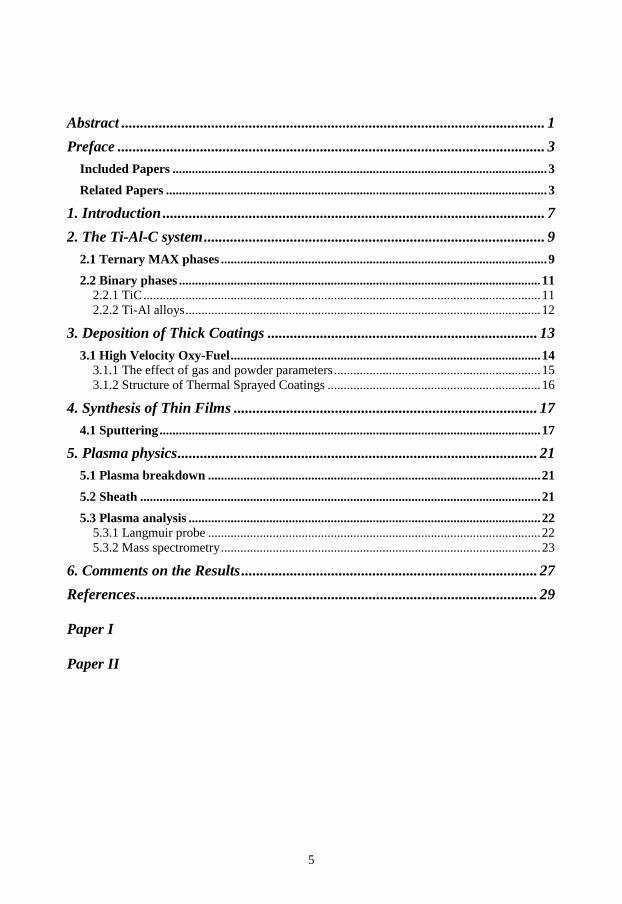
In this section you will be introduced to the phases in the Ti-Al-C system that this work has
shown interest for. First the MAX-phases which have been the model material of my research.
Second, the binary phases which in one way or another play an important role for the
properties in the thin film and coatings. A phase diagram over the Ti-Al-C system is shown
below to give an idea of the relation between these three elements.
Figure 1. The ternary phase diagram for Ti-Al-C system [8].
2.1 Ternary MAX phases
There are three ternary phases within the Ti-Al-C system. Two are MAX phases, namely
Ti2AlC and Ti3AlC2, and one is a perovskite, Ti3AlC. MAX phases are a family of ternary
carbides and nitrides. The name Mn+1AXn describes the elements included where M is a
transition metal, A is an A-element and X is C or N. The stoichiometry can vary (n = 1, 2, or
3) leading to 211, 312, or 413 phases. The crystal structure of Ti2AlC and Ti3AlC2 is
hexagonal with space group P63/mmc and is illustrated in Figure 2. The crystals contain TiC
layers interleaved with single Al layers. The stacking sequence depends on the stoichiometry
where Ti3AlC2, has one Al layer for every third TiC layer, and Ti2AlC, has one Al layer for
every second TiC layer. The TiC is built up by Ti octahedrons connected in each edge with C
atoms filling the octahedral sites.

10
Figure 2. Crystal structure of Ti2AlC (211) and Ti3AlC2 (312).
The atomic binding character in these MAX phases has been shown to be metallic, ionic and
covalent [9]. The covalent-ionic Ti-C bonds are comparable to the bonds in the binary TiC
and are stronger than the metallic Ti-Al bonds present in the ternary structure [10]. The
relatively weak bonds between the TiC and Al layers (basal planes) contribute to an
anisotropic character of the material leading to kink-band formation and delaminations along
the basal planes upon deformation [11]. Due to the mix of strong TiC bonds and metallic Al-
Al bonds the Ti2AlC exhibit both ceramic and metallic properties such as low density of 4.1
g/cm3 and good electrical conductivity (3*106 Ω-1m-1) [9,12]. The bulk modulus (186 GPa) is
lower than for the binary TiC (450 GPa), which yields a more ductile material than the
ceramic itself [10,13]. Further, Ti2AlC exhibits excellent machinability [14] and thermal
shock resistance [12]. The hardness is ~5.5 GPa [12] for bulk material, while for thin films its
been measured to 20 GPa [15].
An interesting feature for the phases Ti2AlC and Ti3AlC2 is their oxidation resistance.
Research has shown that they mainly form Al2O3 scales in oxidizing environments. The oxide
scale exhibits a high density which will slow down diffusion of more oxygen through the
oxide scale to the MAX phase surface and therefore prevent further oxidation [16]. Al2O3
adheres very well to Ti2AlC and does not peel off during thermal cycling even though the
lattice parameters are quite different between α-Al 2O3 (a = 4.76 Å, c = 12.99 Å [17]) and
Ti2AlC (a = 3.04 Å, c = 13.6 Å [18]). The explanation is the thermal expansion coefficient of
α-Al 2O3 [17] which is in the same range as Ti2AlC [19].

11
2.2 Binary phases
2.2.1 TiC
TiC is among the hardest materials known. It has also attracted attention because of its high
melting point and wear resistance. It is widely used as protective coatings for cutting, molding
and milling tools, coatings for ball-bearings and spray gun nozzles as well as for fusion-
reactor applications. TiC has a face-centered cubic close packed crystal structure (NaCl) and
the space group is Fm3m. TiC belongs to the group of interstitial carbides where carbon
occupies the octahedral sites between the close packed Ti atoms – interstitial carbon, see
Figure 3. Interstitial carbides has partly ionic and covalent bonds, but with a metallic
character that causes a relatively low electrical resistivity of 50 µΩcm, compared with Ti of
40 µΩcm [20]. The strong ionic bonds between Ti and C are due to the great difference in
electronegativity of 1.0. TiC exhibits Youngs Modulus of ~450 GPa, a melting point around
3000 °C, density of 4.9 g/cm3 [20]. The hardness is ~25 GPa [21], while for TiC thin films it
can be as high as ~30 GPa [22] due to lattice defects.
Figure 3. NaCl crystal structure of TiC with interstitial C at the octahedral sites.
The TiC is stable over a broad range of compositions. This makes TiC1-x a non-stoichiometric
carbide where a large amount of carbon vacancies may be present. The C content can vary
between 32 and 49 at% [17]. This will cause a variation in cell parameters and consequently
also variations in properties for TiC1-x.
In both Paper I and Paper II TiC is a competitive phase for the synthesis of Ti2AlC coatings.

12
2.2.2 Ti-Al alloys
Ti-Al alloys have a combination of properties such as low density of ~4 g/cm3, good creep
resistance and high strength [23]. This has made them interesting as structural materials at
high temperature which is useful within the aerospace and automotive industry. The phase
diagram below, Figure 4, shows the different Ti-Al phases from Ti-rich Ti3Al to TiAl to Al-
rich Al3Ti. Ti3Al has a hexagonal crystal structure while both TiAl and Al3Ti has a face-
centered cubic crystal structure.
Figure 4. Binary phase diagram of Ti-Al alloys [24].
Properties such as electrical resistivity and creep resistance depend on the microstructure, as
well as, the composition of Ti and Al [25,26]. At high temperatures Ti-Al forms Ti- and Al-
oxides. The formation of oxides are complex and depends on phase composition, temperature,
and oxygen pressure [27,28,29]. It is found that higher Al content (>50 at%) or introduction
of other metals such as Cu will improve the oxidation behavior [30].
In Paper I it is shown that Ti-Al alloys play the role as binding phases and are of importance
for the density and adhesion of the coatings.

13
3. Deposition of Thick Coatings
This section describes thermal spray, a family of established industrial techniques, which
deposit coatings of thicknesses around 100 µm. These techniques utilize thermal energy to
melt and soften particles, which are then accelerated (sprayed) by process gases towards a
substrate. Powder, wire or rods are the most used feed stock for thermal spray, however, gas
and liquids can also be utilized. The span of materials covers ceramics, polymers, and metals.
The focus will be on high velocity oxy-fuel spray, which is the technique used in Paper I.
Thermal spray was invented in the beginning of the 1900’s, but did not enter commercial use
until a half century later. The thermal spray family is divided into three main spraying
techniques; plasma, electric arc, and flame. Plasma spray creates thermal plasma (see Chapter
5) by an electric field which sustains a current as the free electrons move through the ionized
gas. The heavy ions transfer kinetic energy in the gas upon collisions. The energy sources are
usually dc, electric arc or RF. This is a hot spraying technique, which creates plasma
temperatures exceeding 15 000 °C [31] depending on the gas character. The generated particle
temperature reaches 3800 °C [31]. The high kinetic energy of the particles and high degree of
melting generate coatings with a higher density and adhesion to substrate comparable to both
flame and electric arc processes. Oxides will, however, always be present in plasma sprayed
coatings hence vacuum plasma techniques have been developed.
Electric arc utilizes a direct current electric arc which is struck between two wires of spraying
material (conductive) which melts. A fine distribution of molten metal droplets is transported
by a high-velocity air jet which is introduced behind the intersection of the wires. The wires
are continuously fed closer as the material is consumed. Unlike flame and plasma spray, the
droplet cools down immediately as the droplets leave the arc zone and the substrate only get
heated by sprayed particles, which enables spraying on substrates as polymers, wood, and
even paper.
Flame spray was the first invented technique and is mainly used for spraying metals and
alloys. The sprayed material is heated by combustion of fuel gases, most often a mix of
acetylene and oxygen. The melted material is then accelerated by the expanding gas flow.
Flame spray generates the lowest particle velocity of only 80 m/s before impact. The jet
temperature is around 3500 K [31] and is controlled by the fuel/oxygen ratio. Either side of
stoichiometry will cool the flame, but vary between oxidizing (oxygen rich) or reducing (fuel
rich) of the feedstock material. The characteristic for flame sprayed coatings is a density
ranging from 85 to 98 % and relatively high oxide content. Flame spray has, however,
developed during the years and high velocity oxy-fuel is the flame spray technique that offers

14
higher gas velocities and consequently coatings with properties that differ from regular flame
spraying.
3.1 High Velocity Oxy-Fuel
High velocity oxy-fuel (HVOF) uses the heat and velocity from combusted gases. The use of
a combustion chamber and confined nozzles results in particle velocities at supersonic speed.
With such high velocity, the HVOF process exhibits noticeable shock diamond patterns in the
gas jet [32]. A drawback for HVOF is the noise level which is in the range of 125+ to 133+
dBA [31]. The high particle velocity generates coatings with high density and excellent
adhesion. The particle temperature is lower than for plasma spray, which reduces the melting,
decomposition and oxidation. Figure 5 shows a schematic of a high velocity oxy-fuel gun
with its combustion chamber connected with a confined nozzle. The combustion chamber is
air or water cooled to prevent oxidation of the gun components. Oxidation would be
damaging for the spraying process as it reduces the cooling effect further causing powder
build-up and the nozzle to melt. The powder is borne by a carrier gas and fed into the nozzle.
Common gases are hydrogen, propane, kerosene or acetylene mixed with oxygen. Different
shapes of the nozzle create different shapes of the spray pattern.
Cooling in
Cooling out
Oxygen
Powder
Fuel
Combustionchamber
Shockdiamonds
Cooling in
Cooling out
Oxygen
Powder
Fuel
Combustionchamber
Shockdiamonds
Figure 5. Schematic of a High Velocity Oxy-Fuel gun.
Ti2AlC coatings have been deposited with HVOF and characterized in Paper I. A mix of
hydrogen and oxygen gas was used to spray Ti2AlC (MAXTHAL TM 211) powder.

15
3.1.1 The effect of gas and powder parameters
The spraying process is dependent on several parameters, see Figure 6. Two main ingredients
are the powder and gas parameters. They affect the temperature and velocity of the spraying
particles. The particle temperature and velocity will determine the characteristics of the
coating such as adhesion, porosity, and content of unmelted particles and oxides [33]. The
type of gases and the ratio between them will affect the gas temperature. The gas velocity in
combination with the energy from the spraying process plays a main role for both the particle
temperature and velocity. Both gas velocity and temperature varies greatly in the spray
stream, where for instance the core is hot compared to the relatively cold surrounding. There
are both radial and axial gradients of the gas temperature and velocity. Therefore reported
values of dwell time (the time a particle spends in the flame) and temperatures are reported as
average values for the distributions. Longer dwell time, in general, results in higher
concentrations of oxide inclusions. Regarding the powder, the thermal and physical
characteristics are important for the material, i.e. a solid particle melts slower than a porous
granule.
Characteristics ofthe Coating
Particle VelocityParticle Temperature
Total GasflowGas Temperature
Gas TypesGas Ratios
Gas VelocitiesPowder Size
Powder Shape
SprayingGun
Characteristics ofthe Coating
Particle VelocityParticle Temperature
Total GasflowGas Temperature
Gas TypesGas Ratios
Gas VelocitiesPowder Size
Powder Shape
SprayingGun
Figure 6. Illustration of the spraying process

16
3.1.2 Structure of Thermal Sprayed Coatings
A coating is built up by molten or heated particles that spread out and solidify very fast upon
impact, so called splats [34], see Figure 7. The fast cooling rate yields formation of
amorphous and metastable phases. The build-up of splats may yield a lamellar microstructure
and often a very rough surface which for certain applications are be machined off. The
substrate surface is sand-blasted to create a rough surface in which the splats can hook on to
and create a good adhesion which mainly has a mechanical character rather than chemical
[35]. The degree of melting of the particles affects the splat formation and determines the
cohesion and porosity of the coating.
Splat
Unmeltedpowdergrain
Oxide
Figure 7. Schematic cross section of a thermal sprayed coating.
Porosity leads to poor cohesion within the coating, low wear resistance, low hardness and
high corrosion rate. Open porosity means that a corroding agent can reach the substrate. On
the other hand the porosity can be utilized to produce oil-impregnated coatings and is desired
for thermal barrier coatings (TBC) to increase the thermal properties.
Oxides are present in most thermal sprayed coatings. The oxides are created during spraying
when heated particles and the surface of the coating interact with the surrounding and can
often be seen as dark elongated strings parallel to the substrate. Oxides have a high hardness
and therefore often contribute to the average hardness of the coating and also cause
brittleness. Because of this, oxides are most of the times not wanted but there are cases where
oxides are desired because they increase the wear resistance or lower the thermal
conductivity.

17
4. Synthesis of Thin Films
This section describes deposition techniques, which utilizes vapor of either molecules or
atoms to grow thin films of ~1µm. The deposition rate depends on the technique but is in
general slower than thermal spray processes. The focus in this Thesis is on magnetron
sputtering, which is the technique used in Paper II.
Two main groups of deposition techniques are chemical vapor deposition (CVD) and physical
vapor deposition (PVD). CVD utilizes volatile gases as starting material which react at the
substrate surface to grow the coating at thermal equilibrium. This technique offers deposition
of complicated geometries at high rate. Disadvantages are the use of high substrate
temperature which limits the choice of substrate material, and some of the gases used are
hazardous. In comparison, PVD make use of vaporization of solid material that condenses on
the substrate surface. It can only deposit line-on sight, but operates at much lower
temperatures than CVD. The low temperature and low pressure offers deposition far from
thermal equilibrium and therefore potential growth of metastable phases. There are several
ways to vaporize a solid material. Pulsed laser deposition (PLD) vaporizes the material with a
high energy laser. Cathodic arc deposition and magnetron sputtering are two techniques that
utilize plasma instead.
4.1 Sputtering
Condensation of a material must take place in a vacuum chamber to control the growth and
obtain high purity of the films. The sputtering process utilizes a source of material (target)
with applied negative voltage that attracts relatively heavy ions (from a plasma) and knocks
out atoms from the target. These atoms are deposited one by one to grow a well-defined
coating. The target can consist of a metal, a ceramic or a target of different phases and is
mounted in a magnetron. In most cases argon gas is used for the plasma, but oxygen and/or
nitrogen can be introduced as reactive gases to obtain ceramic coatings. This process is called
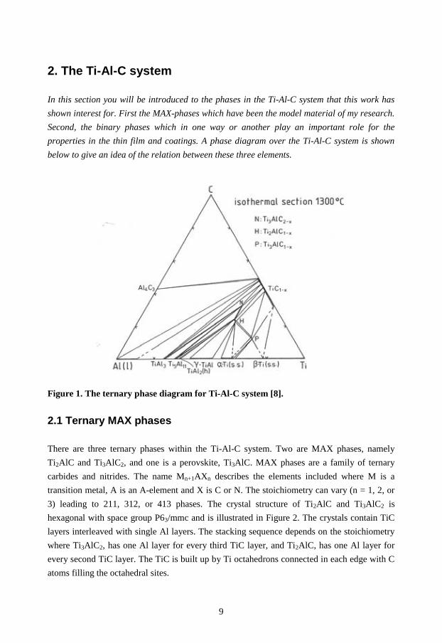
reactive sputtering. The sputtering process is illustrated in Figure 8 and will be described in
more detail below.
18
PlasmaPlasma
Cathode (-)
Substrate on sub. holder
Ar+
Ar+
Ar+
Ar+
Ar+
Film growth on substrate
Sputtering of target
Figure 8. Schematic of the magnetron sputtering process.
In the same moment as the plasma is created the sputtering and deposition can take place. By
the use of magnets, mounted behind the target, a magnetic field is applied to gather electrons.
A high electron density is preferred close to the target to amplify the ionization of the plasma
gas and increase the sputter rate. The argon ions must have enough momentum upon impact
on the target to break bonds in the material and to transfer sufficient kinetic energy to the
outgoing atoms. The now free atoms travel through the plasma of argon ions and electrons.
The probability of the atom to hit argon ions depends on the pressure. Some sputtered atoms
will reach the substrate without interfering with other plasma species, but most atoms will go
through collisions and lose some of their kinetic energy. Many sputtered atoms will lose all of
their initial kinetic energy and move randomly. These atoms are called thermalized.
Some elements are easier to sputter (knock out from the target) than others. The sputter yield
states how many sputtered atoms you get from one incoming ion, in other words, the
efficiency of sputtering. Values usually range from 0.1 to 10 [36]. Special interest for this
Thesis is the sputtering yield of Ti, Al, and C. Sputtering with 0.5 keV Ar ions results in a

19
sputtering yield of 0.51 for Ti, 1.05 for Al and 0.12 for C [36]. When sputtering from an alloy
target of many elements the difference in sputtering yield will be compensated for by a
composition difference at the surface of the target [36]. If this can be applied to a Ti2AlC
target it would lead to a surface containing less of the elements that are easy to sputter, i.e.,
Al, and more of the elements that are harder to sputter, i.e., Ti and C when equilibrium is
reached. As a result the out-flow from the target has a content of Ti, Al, and C representing
the nominal composition of the target.
The substrate is most often heated to favor mobility of the arriving atoms. Most materials can
be used as substrates as long as it can handle the temperature required for deposition. A
negative voltage (bias) applied to the substrate can acquire different effects depending on its
magnitude. A low voltage increases the mobility of the arriving atoms. A voltage around 100
V makes it possible to etch or sputter the surface. Higher voltage in the range of 1000 V will
implant atoms into the coating or substrate.
In paper II, direct current magnetron sputtering has been utilized to deposit Ti-Al-C thin films
in an ultra high vacuum (UHV) chamber.

20

21
5. Plasma physics
There are four states of matter; solid, liquid, gas, and plasma. A plasma can be described as
a cloud of positive and negative charges. The overall net charge is zero, meaning that there
are just as many positively charged ions as negative electrons. We have many kinds of plasma
around us for instance in northern lights and the sun. Plasma is also used in many different
applications and plasma physics is a well established research area. Its fascinating light is
used for neon signs and energy lamps. High-energetic plasma is used for thermal spraying, as
cutting tools or in disinfection processes. In this Thesis the plasma is used as a tool for
depositing thin films (see section 4.1) and this chapter will bring up a few phenomenons
within plasma physics and techniques for plasma analysis.
5.1 Plasma breakdown
The creation of a plasma in a gas is called plasma breakdown. For the sputtering process Ar
gas is introduced into the vacuum chamber and an electric field is applied between the
chamber (anode) and the target (cathode). Due to background radiation there are always a
number of ions and electrons present. The electrons will accelerate towards the chamber walls
and the ions are attracted to the target. When ions get close to the target, electrons from the
target tunnel and neutralize the ions. Energy corresponding to the ionization energy is
released. If this energy is greater than the work function for the electrons in the target it will
release secondary electrons which will be transported to the plasma and ionize more argon
atoms. A plasma of ions and electrons is now created.
5.2 Sheath
In the region between the plasma and a solid, in our case the chamber wall, a sheath is
created. Since the electrons are much smaller and have a much higher velocity than the ions
they will reach the solid surface first. The surface will get negatively charged and attract
positive ions. A sheath is the region over which a potential difference occurs between the
solid and the plasma. The thickness of the sheath depends on the magnitude of the potential
between the negatively charged wall and the positive layer covering it. The thickness is in the
range of the Debye length (λD), which is defined as
5.0
20
=ne
kTeD
ελ ,

22
Where ε0 is the permittivity of free space, k is Boltzmann’s constant, Te is the electron
temperature, n is the plasma density, and e is an elementary charge. The Debye length gives
important plasma information about the behavior around inserted objects and ability to
penetrate holes.
5.3 Plasma analysis
5.3.1 Langmuir probe
The Langmuir probe is an electrostatic probe used to determine the electron temperature and
the plasma density (number of ions in a volume). Electron temperature is related to its
velocity and is a measure of the electron energy. The electron temperature in a plasma can
reach thousands of degrees. However, due to the low pressure and low mass of the electron
the energy transfer is negligible.
The probe is simply one or several electrodes connected to a voltage source. The probe is
inserted to the plasma, a voltage is applied with respect to ground and the current is measured.
From an I-V graph (illustrated in Figure 9) one can extract the electron temperature, plasma
density, floating potential, and plasma potential. When a probe without an applied voltage (or
any object) is inserted in a plasma, the net voltage is slightly negative and the probe current is
zero. It means we have no net current of electrons (Ie) or ions (Ii), Ie = Ii. The negative voltage
is called floating potential, Vf, and is due to the fact that electrons have a higher mobility and
will reach the electrode faster and cause a negative charge. At voltages below the floating
potential, the probe draws mainly ion current (ion collects electrons from the probe) and as
the probe gets saturated the curve flattens out. At the plasma potential, Vp, the probe draws
mainly electron current. At voltages above the plasma potential the probe gets saturated by
electrons instead and the curve flattens out.

23
Figure 9. I-V graph for a Langmuir measurement in a plasma during sputtering from a
Ti2AlC target.
5.3.2 Mass spectrometry
Mass spectrometry is used to analyze the chemical and energy distribution of ion species.
The ions can be both elemental and molecules which makes mass spectrometry useful for
both inorganic and organic chemistry as well as for physics. This section focuses on mass
spectrometry for plasma analysis.
The mass spectrometry technique separates ions according to their mass (m) and charge (q),
called mass ratio, M.
q
mM = (1)
The ions are first accelerated by a potential (V) giving them a specific kinetic energy (Ekin).
2
2mvqVEkin == (2)
24
From equation (1) and (2) the relation between mass ratio and voltage is derived.
q
m
vV =
2
2 (3)
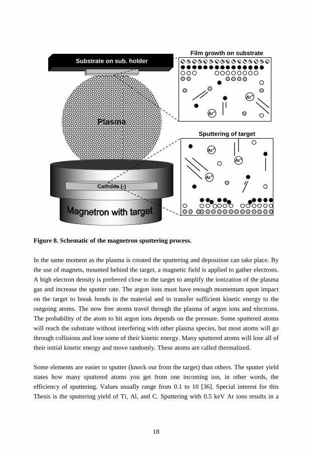
When scanning over a voltage range, ions are separated by mass and let through to the
detector to be analyzed. The mass spectrometry equipment works under low pressure to
increase the mean free path of the species. The species enters an orifice which can either be
electrically floating, biased or grounded. If investigating neutral species there must be an
ionization source inside the orifice. A common source would be a filament that emits
electrons. Next there is an energy filter and a mass filter. The combination of energy and mass
filters is required for measurements of the energy distribution for species with different
masses, but also to improve the resolution for mass scans by filtering out the low energy ions.
The detector consists of an electron multiplier to increase the intensity. The instrumental setup
is illustrated in Figure 10.
Plasma
Energy Analyzer
Mass Analyzer
Detector
Ionizer
Pumpsystem
Plasma
Energy Analyzer
Mass Analyzer
Detector
Ionizer
Pumpsystem
Figure 10. General principle for a mass spectrometer.
Two main spectrometers are available, either a mass energy analyzer (MEA) or a time of
flight (TOF). A mass energy analyzer has separated energy and mass filters. The energy filter
uses an electric field to only allow ions with a specific kinetic energy to pass through. A
common mass filter is the quadrupole which consists of four cylindrical electrodes mounted

25
parallel to the ion path in a square array. A quadrupole is illustrated in Figure 11. A potential
is applied over each diagonal pair of electrodes. The potentials are a combination of both dc
and rf and are synchronized between the pairs. Ions entering the quadrupole will start to
oscillate. At a specific dc and rf potential only ions with the right mass-to-charge ratio will get
a limited oscillation and pass through the quadrupole without smashing into the electrodes.
The velocity of the ions will not affect the amplitude of the oscillation and consequently not
affect the result. The resolution is determined by the ratio between dc and rf voltage which is
kept constant during the mass scan [37].
--
+
+
-
-
--
+
+
-
-
Figure 11. Schematic of a quadrupole.
A time of flight mass spectrometer utilizes the kinetic energy discussed above, see equation
(2).
2
2mvEkin =
Ions with the same kinetic energy will separate due to mass because lighter ions will travel
faster than heavier ions. The detector will then distinguish the different ions due to the time it
takes for the ion to reach the detector. The peak broadening gives information about the
energy distribution.

26

27
6. Comments on the Results
Here I summarize and discuss the results from the papers of this Thesis. The papers differ by
the choice of deposition technique used for Ti2AlC coatings. Paper I focuses on high velocity
oxy-fuel spraying and Paper II presents synthesis by the direct current magnetron sputtering
technique.
Paper I We demonstrate how Ti2AlC coatings can be produced by the high velocity oxy-fuel (HVOF)
thermal spray technique. Ti2AlC (MAXTHAL 211) powder was used as a source of material
and the coatings were sprayed with a combustion gas of H2 and O2 . The study also focuses on
how the powder size and the total gas flow affects the microstructure as well as the phase
content. We find that coatings sprayed with a relatively coarse powder of ~56 µm exhibit a
high content of Ti2AlC, which is not surprising considering that large powder melts to a
smaller extent. It is, however, at the expense of a more porous coating with cracks and
delaminations. When spraying with a finer powder of ~38 µm the amount of Ti2AlC is found
to range with the total gas flow of H2 and O2. This means that a finer powder is more sensitive
to heating as the gas ratio affects the power of the flame. The coatings are dense and exhibit
good adhesion to stainless steel substrates. In addition to Ti2AlC, other phases such as TiC,
and AlxTiy alloys are present in the coatings and their content also scales with the gas mix
ratio. A model for the operating phase transformations is also suggested.
By introducing Ti2AlC to a new area of deposition techniques there are a lot of interesting
topics to continue this research within. More investigations about the mechanical properties of
these coatings are needed as well as oxidation studies in different environments. Parallel to
this, fundamental studies to receive a deeper understanding on the phase transformations
during spraying would be of interest to be able to fine-tune the process.
28
Paper II In this study we have investigated a new way of utilizing a previously reported, but not fully
described deposition technique for MAX phase thin films. By using one compound target for
d.c. magnetron sputtering instead of three elemental targets the aim is to simplify the
sputtering process and make up-scaling possible for industrial purposes. The on-set for my
study is the phenomenon on a non-conserved composition between the compound target and
resulting film.
Ti-Al-C thin films were sputtered on Al2O3 0001 substrates at temperatures between ambient
and 1000 °C and at target-to-substrate distances of 6 or 9 cm. Sputtering from a compound
target was shown to yield film compositions other than the nominal content of the target.
Especially the carbon content was remarkably high exceeding even the content of Ti. This is
partly explained by differences in transport where a substantial part of the carbon was shown
to exhibit a relatively high kinetic energy when reaching the substrate surface. It is also
suggested to be an effect of gas-phase scattering processes in combination of the angular
distribution of the sputtered species. The Al content was affected by the substrate temperature
around 700 °C due to its high vapor pressure. It is suggested that if the Ti/C ratio is correct
Ti2AlC can be synthesized at higher temperatures even with Al-poor contents. This was also
demonstrated by co-sputtering with an additional Ti target which yielded a Ti2AlC thin film.
The possibility of employing a compound target with a composition that compensates for the
apparent Ti and Al loss during deposition for MAX-phase growth is a topic for future
investigation.
The microstructure of the Ti2AlC film showed two kinds of grains with different out-of-plane
orientations which both seems to have taken part in a solid state reaction with the Al2O3
substrate. Further investigation for the understanding of this reaction would be interesting, as
would any reaction with other substrate materials. As the reaction includes high contents of
oxygen, future studies of oxygen incorporation in a range of MAX phases are of interest as
has been recently been reported by Rosén et al. for the case of Ti2AlC [38].

29
References
[1] W. Jeitschko, H. Nowotny, Montashefte für Chemie 98 (1967) 328
[2] M.W. Barsoum, T. El-Raghy, Journal of the American Ceramic Society 79 (1996) 1953
[3] N.V. Tzenov, M.W. Barsoum, Journal of the American Ceramic Society 83 (2000) 825
[4] J.D. Hettinger, S.E. Lofland, P. Finkel, T. Meehan, J. Palma, K. Harrell, S. Gupta, A.
Ganguly, T. El-Raghy, M.W. Barsoum, Physical Review B 72 (2005) 115120
[5] S. Amini, M.W. Barsoum, T. El-Raghy, Journal of the American Ceramic Society 90
(2007) 3953
[6] J.J. Nickl, K.K. Schweitzer, P. Luxenberg, Journal of the Less-Common Metals 26 (1972)
335
[7] T. Seppänen, J.-P. Palmquist, P.O.Å. Persson, J. Emmerlich, J. Molina, J. Birch,
U. Jansson, P. Isberg, L. Hultman, Proceedings of the 53rd Annual Meeting of the
Scandinavian Society for Electron Microscopy 142 (2002) ISSN: 1455
[8] M.A. Pietzka, J.C. Schuster, Journal of Phase Equilibria 15 (1994) 392
[9] Y. Zhou, Z. Sun, Physical Review B 61 (2000) 12570
[10] Z. Sun, D. Music, R. Ahuja, S. Li, J.M. Schneider, Physical Review B 70 (2004) 092102
[11] Y.C. Zhou, X.H. Wang, Materials Research Innovations 5 (2001) 87
[12] M.W. Barsoum, D. Brodkin, T. El-Raghy, Scripta Materialia 36 (1997) 535
[13] B. Manoun, R.P. Gulve, S.K. Saxena, S. Gupta, M.W. Barsoum, C.S. Zha, Physical
Review B 73 (2006) 024110
[14] M.W. Barsoum, M. Ali, T. El-Raghy, Metallurgical and Materials Transaction A 31
(2000) 1857
[15] O. Wilhelmsson, J.-P. Palmquist, Applied Physics Letters 85 (2004) 1066
[16] X.H. Wang, Y.C. Zhou, Corrosion Science 45 (2003) 891
[17] Alumina as a Ceramic Material, W. H. Gitzen [Ed.], The American Ceramic Society,
Westerville, Ohio (1970) ISBN 0-916094-46-4
[18] M.W. Barsoum, Progress in Solid State Chemistry 28 (2000) 201
[19] M. Sundberg, G. Malmqvist, A. Magnusson, T. El-Raghy, Ceramics International 30
(2004) 1899
[20] Handbook of Refractory Carbides and Nitrides, Hugh O. Pierson, Noyes Publications,
Westwood, New Jersey, USA ISBN: 0-8155-1392-5
[21] W.S. Williams, Progress in Solid State Chemistry 6 (1971) 57
[22] H. Högberg, J. Birch, M. Oden, J.O. Malm, L. Hultman, U. Jansson, Journal of Materials
Research 16 (2001) 1301
[23] F. Appel, R. Wagner, Materials Science and Engineering R22 (1998) 187
30
[24] Binary Alloy Phase Diagram, J.L. Murray, American Society for Metals, Metals Park
Ohio, USA 1986
[25] D. Veeraraghavan, V.K. Vasudevan, Materials Science and Engineering A 192/193
(1995) 950
[26] M.F. Bartholomeusz, M.A. Cantrell, J.A. Wert, Materials Science and Engineering A201
(1995) 24
[27] A. Rahmel, P.J. Spencer, Oxidation of Metals 35 (1991) 53
[28] V. Maurice, G. Despert, S. Zanna, P. Josso, M.-P. Bacos, P. Marcus, Acta Materialia 55
(2007) 3315
[29] K. Kovács, V.K. Josepovits, G. Kiss, H. Zillgen, P. Deák, Physica Status Solidi 193
(2002) R1
[30] J. Lee, W. Gao, M. Hodgson, International Journal of Modern Physics B 17 (2003) 1711
[31] Handbook of thermal spray technology, J.R. Davis, American Society for Metals,
Metals Park, Ohio, USA (2005) ISBN 0-87170-795-0
[32] A. Dolatabadi, V. Pershin, J. Mostaghimi, Journal of Thermal Spray Technology 14
(2005) 91
[33] M. Li, P.D. Christofides, Journal of Thermal Spray Technology 13 (2004) 108
[34] V.V. Sobolev, Materials Letters 36 (1998) 123
[35] C.R.C. Lima, J.M. Guilemany, Surface and Coatings Technology 201 (2007) 4694
[36] Materials Science of Thin Films, M. Ohring, Academic Press, London UK 2002
[37] J.P. Eberhart, Structural and Chemical Analysis of Materials, Wiley, (1991)
ISBN: 0471929778
[38] J. Rosén, P.O.Å. Persson, M. Ionescu, A. Kondyurin, D.R. McKenzie, M.M.M. Bilek,
Applied Physics Letters 92 (2008) 064102


![PASSIVATION STUDY OF Ti3AlC2 AND Ti2AlC IN SELECT ACIDIC … · 2020. 2. 28. · phase in HCl and H 2 SO 4 [14]and also the corrosion behavior of certain MAX phases in NaOH, HCl and](https://img.dokumen.tips/doc/110x75/613092881ecc515869442eeb/passivation-study-of-ti3alc2-and-ti2alc-in-select-acidic-2020-2-28-phase-in.jpg)