Embed Size (px)
Citation preview

1
Characterization of the surface and physical properties of South African
coal fly ash modified by sodium lauryl sulphate (SLS) for applications in
PVC composites
E. M. van der Merwea*, C.L. Mathebulaa and L.C. Prinsloob
aDepartment of Chemistry, University of Pretoria, Pretoria, 0002, South Africa
bDepartment of Physics, University of Pretoria, Pretoria, 0002, South Africa
ABSTRACT
The application of coal fly ash as mineral filler in polymers is hampered by the aggregation of the
ash particles and a lack of interaction between the ash and polymer. Therefore surface treatment is
usually performed on mineral fillers to enhance workability and compatibility between the polymer
and filler. In this study, a commercially available South African coal fly ash sample was surface
modified under a variety of conditions with an anionic surfactant, sodium lauryl sulphate (SLS), with
the aim to alter the surface properties of the ash. The properties of the modified products were
compared to those of the untreated samples by means of scanning electron microscopy (SEM),
transmission electron microscopy (TEM), thermogravimetric analysis (TGA-IR), Fourier transform
infrared spectroscopy (FTIR), X-ray diffraction (XRD) X-ray fluorescence spectroscopy (XRF). A
small shift of the S-O stretch vibration in FTIR spectra of SLS treated fly ash is indicative of
interaction between fly ash and SLS. Although the overall chemical composition of the SLS
modified coal fly ash sample was not altered extensively, significant changes could be observed in
its physical properties. Contact angle measurements indicated that the hydrophilic surface of
untreated fly ash was rendered hydrophobic after SLS treatment. SEM and TEM results showed
agglomerates on the surface of most of the fly ash spheres. Feasibility tests of using fly ash
samples as filler in PVC indicated that SLS treated fly ash can successfully replace CaCO3 as filler
in PVC under conditions of low filler loadings.
KEYWORDS: coal fly ash (FA), surfactant, sodium lauryl sulphate, SLS, surface modification, PVC

2
1. Introduction
A very small percentage of coal fly ash produced worldwide is currently being exploited and with
the growing concern about pollution and increasing landfill costs, there has been global interest to
increase the utilization of coal fly ash. Benefits for doing so include a reduction in the usage of non-
renewable natural resources and the substitution of materials that may be energy intensive to
manufacture. One possible use of coal fly ash is as filler in polymers and rubber.
Fillers are generally used in polymers and rubber to reduce their production costs and to improve
certain physical characteristics. The physical properties of coal fly ash make it a suitable filler for
polymers. In particular, the sphericity of coal fly ash particles facilitates dispersity and fluidity within
polymeric materials, while the reduced density and cost of fly ash adds to the list of advantages
when compared to conventional fillers. However, the application of coal fly ash in these fields is not
common yet. One of the principle problems is that there is no binding between the polymer and fly
ash, with the consequence that the quality of the product is unsatisfactory. Another concern is the
agglomeration between fly ash particles, which has an adverse effect upon its workability as filler. If
the surface properties of fly ash can be modified in such a way that these problems are conquered,
a new market for the utilization of fly ash can materialize.
Research in the field of utilizing fly ash as filler in different polymeric materials is growing
exponentially [1-11]. Surface treatment is a principal method applied to change the wetting
behaviour of mineral or inorganic fillers. Surfactants are generally used as surface modifiers to
increase the hydrophobicity of the surface of hydrophilic inorganic fillers, which consequently
increases compatibility between the polar inorganic and non-polar organic matrices. Nath et al [7,
8] studied the effect of surfactant sodium lauryl sulphate (SLS) modified fly ash on the properties of
composite films fabricated with polyvinyl alcohol (PVA). Their results showed an enhancement in
the physical properties (increased tensile strength) of the polymer, which they attributed to the
elimination of particle-particle interaction, and a better distribution of fly ash within the polymer. The
composition and morphology of the fly ash used in the study performed by Nath [7, 8] differ from

3
that of South African fly ash, and the method would not necessarily be successful when applied to
South African fly ash.
In a preceding paper the bulk and surface properties of the classified South African FA sample
used in this study was characterized using a variety of techniques [12]. In this study we develop a
method for modifying the surface properties of this sample using sodium lauryl sulphate (SLS) and
report the changes in properties (including surface coverage) as well as feasibility tests to
determine whether SLS modified fly ash can be used as replacement of the conventionally used
CaCO3 as filler in PVC.
2. Material and Methods
2.1. Materials
The coal fly ash (FA) utilized in this study was obtained from the Ash Resources Pty Ltd ash
beneficiation site at Eskom’s Lethabo Thermal Power station. The fly ash is classified on site and is
specified to have a mean particle size between 3.9 and 5.0 μm with more than 90% of its particles
with diameters less than 11 μm. After classification it is marketed as a very fine, spherical,
pozzolanic and highly reactive alumino-silicate with low carbon content. Sodium Lauryl Sulphate
(SLS) with a purity of 98% was obtained from Merck and was used as received
2.2. Coal Fly Ash modification
20 g of a dry FA sample was either mixed with 200 ml distilled water or the relevant SLS solution.
The effect of varying the surfactant concentration (0.1%, 0.5% and 2.0% wt), temperature of
treatment (50 °C and 80 °C) as well as treatment time (6, 18 and 66 hours) was studied. The FA
aqueous suspensions were treated in a shaking waterbath at the relevant temperature while
shaking continuously at 130 revolutions per minute.

4
For the reflux experiments, a reflux system consisting of a heating mantle, round bottom flask and
condenser was assembled. The mixtures were refluxed for 6 hours using water and SLS solutions
with concentrations of 0.5%, 2.0%, and 4.0% by weight.
After the respective treatments, the samples were washed with distilled water numerous times
under vacuum filtration, and subsequently dried for 2 days at 50 °C in a laboratory oven. A new
surfactant solution was prepared every day, in order to minimise chances of decomposition of SLS
that may occur during storage [13].
2.3. Chemical analysis by X-ray fluorescence spectroscopy (XRF)
XRF was used to determine the bulk chemical concentrations of major elements in the untreated
FA sample. No milling was required prior to the analysis. The analysis was performed on an
ARL9400XP+ XRF spectrometer (Thermo ARL, Switzerland). The loss on ignition (LOI) was
determined by roasting the sample at 1000 °C for at least 3 hours until a constant weight was
obtained. A glass disk was prepared by fusing a mixture of 1 g of the FA sample with 6 g of Li2B4O7
at 1000 °C.
2.4. X-ray diffraction (XRD) analysis
The mineralogical composition of the FA sample was obtained by XRD. The XRD patterns were
collected from 5° to 90° on a PANalyticalX’Pert Pro powder diffractometer with X’Celerator detector
and variable divergence and fixed receiving slits with Fe filtered Co-Kα radiation. The phases were
identified using X’PertHighscore plus software. The relative phase amounts were estimated using
the Rietveld method (Autoquan Program). Twenty percent silicon (Aldrich 99% pure) was also
added to each sample for the determination of amorphous content. The samples were then
micronized in a McCrone micronizing mill, and prepared for XRD analysis using a back loading
preparation method.
2.5. Scanning electron microscopy (SEM)
The FA powder was mounted on a double-sided carbon tape by dipping carbon stubs into the
samples. Excess material was removed by gentle blowing with compressed nitrogen. The samples

5
were then coated with either gold or carbon using a Sputter-coater (Emitech K550X, Ashford,
England).
The gold coated samples were analysed on a JEOL JSM 840 Scanning Electron Microscope
(SEM), operated at 5kV. Images were collected with the aid of a flame-grabber (Orion Version 6).
To study the carbon coated samples, a Zeiss Ultra SS (Germany) field emission scanning electron
microscope (FESEM), operated at an acceleration voltage of 1 kV, was used under high-vacuum
conditions.
2.6. Transmission electron microscopy (TEM)
A JEOL JEM 2100F TEM was used to study the topography of the FA. The samples were
dispersed in 100% ethanol with the aid of sonication. A drop of the diluted suspension was poured
onto a copper grid which was then placed into the sample injection holder for analysis.
2.7. Infrared spectroscopy (FTIR) studies
Mid-infrared spectra were recorded with a Brüker 70v Fourier transform infrared (FTIR)
spectrometer, by placing the finely grounded samples in a diamond ATR (attenuated total
reflection) cell. The resolution was 2 cm-1 and 32 scans were signal-averaged in each
interferogram.
2.8. TGA-IR analyses
TGA-IR analyses were performed on a Perkin Elmer Spectrum 100 FT-IR spectrometer coupled to
a Perkin Elmer TGA 4000 Thermogravimetric Analyzer. Approximately 20g was placed on an
alumina pan and heated in air at 10 ºC/min.
2.9. Contact angle
Contact angle measurements were performed on an OCA-20 Contact Angle-meter (Data Physics
Instruments), using the sessile drop method with water as wetting liquid. To perform these
measurements, a small drop of water is deposited on the surface of a FA powder bed which was

6
fixed to a microscope slide by double-sided tape. A picture of the profile of the drop is taken about
1 second after contact with the powder surface. The reported result is the average of three
measurements.
2.10. Preparation of FA-PVC composites
In order to investigate the effect of surface modification on a PVC composite, the untreated FA
sample, 4.0% SLS reflux FA sample and a 2.0% stearic acid coated CaCO3 filler was used.
Flexible PVC composite sheets were made using a Ca/Zn stearate stabiliser and dioctyl phthalate
plasticiser. Three different ratios of filler to resin were used, as indicated in Table 1. For
comparison purposes, a 2.0% stearic acid coated CaCO3 filler was included in at a filler to resin
ratio of 30 phr, keeping the amounts of stabilizer and plasticiser the same as for the 30 phr FA
filled PVC samples.
Table 1: Formulation of the PVC composites
Material Parts per hundred resin
(phr)
PVC S68 100
Filler (Fly ash or CaCO3) 30, 40 or 70
Stabiliser (Ca/Zn stearate) 3
Plasticiser (Dioctyl phthalate) 40
The dry samples, which include the PVC resin, the filler, and the stabiliser, were mixed together in
a high speed mixer for 3 minutes before the liquid plasticiser was added to the mix. After adding
the plasticiser, the contents were mixed together in the mixer for a further 5 minutes. The sample
was collected and milled on a two roll bridge mill at 168 ºC.
2.11. Tensile tests
Tensile testing was performed at a constant speed of 50 mm/min with a gauge distance of 50 mm
according to ISO 527 for tensile strength and elongation analysis on flexible sheets; along the
direction of milling as well as the transverse direction. The samples were cut with a die cutter, and
the data reported is the average of 5 specimens taken from each direction. The samples were

7
conditioned in the laboratory for 36 hours at 23 °C and a humidity of 43% before performing tensile
tests.
2.12. Relative density
The relative densities of the PVC composites were measured at 25 °C and a pressure of 1 atm
using a Micromeritics AccuPyc II 1340 Gas Pycnometer.
3. Results and discussion
3.1. Chemical and mineralogical characterisation
The chemical composition as determined by XRF analysis (Table 2) is typical of a Class F coal fly
ash, and the low loss on ignition value indicates that the ash contains a very low percentage
moisture, carbonates and hydroxides. This result was confirmed by TGA analyses (Section 3.5,
Figure 7).
XRD analysis (Figure 1) determined that the FA sample was predominantly composed of an
amorphous alumina silica glass phase (62.1%), and that the two main crystalline phases were
mullite (31.8%) and quartz (6.1%). No significant difference was observed between the quantitative
Table 2: Elemental bulk composition of the fly ash sample, as determined by XRF (major elements)
Composition Weight %
SiO2 49.30 TiO2 2.01 Al2O3 34.00 Fe2O3 5.78 MnO 0.05 MgO 0.99 CaO 5.06 Na2O <0.01 K2O 0.87 SO3 0.24 P2O5 0.59 Cr2O3 0.07 NiO 0.05 V2O5 0.04 ZrO2 0.08
Loss on Ignition 0.52 Total 99.63

8
XRD analysis of the untreated FA and SLS modified FA samples as expected as interaction
between FA and SLS is purely a surface effect.
Figure 1: XRD analysis
3.2. Morphological characterisation
The results obtained from SEM measurements for the untreated FA and the FA samples treated
with varying concentrations of SLS for 6 hours at 80°C in the shaking water bath are shown in
Figure 2. It is clear that the samples have good sphericity and a decrease in the formation of
agglomerates (Figure 2) occur as the concentration of SLS increases; indicating that SLS
Untreated FA 0.1% SLS 2.0% SLS
Figure 2: Results obtained from SEM measurements for the untreated FA and the FA samples treated
with varying concentrations of SLS for 6 hours at 80 °C in the shaking waterbath

9
treatment of FA samples improves the separation between particles. It should be noted that water
treated samples also showed a slight reduction in agglomeration which could be due to mechanical
action, as samples were subjected to vigorous shaking during treatment. Considering temperature
conditions, the extent of particle separation was greater for the samples treated at 80 °C than at
50 °C, and therefore only the results obtained for the 80 °C treatments are shown here.
Untreated FA 6 hours 66 hours
Figure 3: Effect of increasing the treatment time (80 °C)
The effect of increasing the treatment time (80°C) is shown in Figure 3 and it is clear that the SLS-
FA sample treated for 6 hours shows a higher degree of particle separation in comparison to the
66 hours treated sample. One explanation may be that the presence of silanol groups on the
surface of the fly ash particles causes strong interactions between particles leading to
agglomeration as reported by Wolff [14] for a filler in a rubber matrix. On the other hand it has been
reported by Sugàr et al [13], that SLS solutions will degrade with time, and that fresh solutions
need to be prepared on the day of use. It is possible that the SLS solutions decayed during
treatment leading to a decrease in separation of agglomerates. Further investigation is necessary
for clarification
A summary of the most promising results, obtained from FESEM analysis, is shown in Figure 4.
The occurrence of agglomerates on the surface of the SLS-modified FA samples is clear. The
agglomerates on the surface of the FA sample treated in 4.0% SLS under reflux conditions seem
to be more evenly distributed compared to those on the surface of the FA sample treated in a 2.0%
SLS solution at 80 °C.

10
Untreated FA 2% SLS, 6h at 80°C 4% SLS reflux
Figure 4: Summary of the most promising results, obtained from FESEM analysis
Particle coating was observed for all the SLS reflux treated samples with a higher degree of
surfactant coverage on the surface of the 2.0% and 4.0% SLS modified FA, whereas significant
numbers of FA particles of these treated samples were found to be coated. The FESEM images of
the SLS refluxed FA samples show an even distribution of the coating of particles as well as the
density of the coating, indicating that most of the FA particles were coated with the surfactant.
3.3. Topographic characterisation
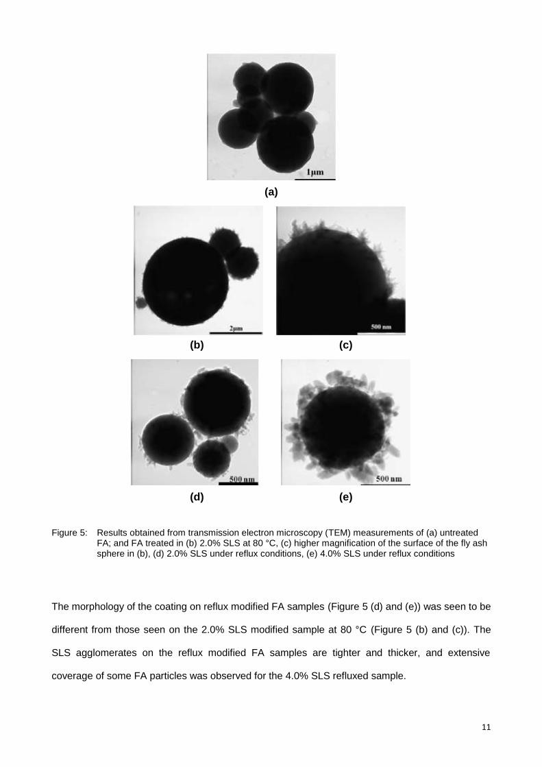
Results obtained from Transmission Electron Microscopy (TEM) measurements are summarized in
Figure 5. Most of the TEM images show agglomerates on the surface of the fly ash spheres.
However, there is a distinct difference between the morphology of these agglomerates on the
untreated and SLS modified FA. The agglomerates on the untreated FA spheres are considerably
less than those on the SLS modified FA. Not all SLS modified FA particles were covered with
agglomerates to the same degree. This is depicted for the FA sample treated in 2.0% SLS at 80°C
in Figure 5 (b). Under the same treatment conditions, some FA spheres had a low degree of
coverage, while others were covered extensively. Also, the needle-like shape of the agglomerates
on the SLS modified FA was different from that of the agglomerates observed on the untreated
(Figure 5(a)) and water treated FA surfaces (not shown), which were more rounded in shape. Both
Chen [15] and Hower [16] described the occurrence of carbonaceous agglomerates on different
types of untreated FA particles. The morphology of the agglomerates described by these authors
was distinctly different from that observed in the SLS modified FA in this study.
11
(a)
(b) (c)
(d) (e)
Figure 5: Results obtained from transmission electron microscopy (TEM) measurements of (a) untreated FA; and FA treated in (b) 2.0% SLS at 80 °C, (c) higher magnification of the surface of the fly ash sphere in (b), (d) 2.0% SLS under reflux conditions, (e) 4.0% SLS under reflux conditions
The morphology of the coating on reflux modified FA samples (Figure 5 (d) and (e)) was seen to be
different from those seen on the 2.0% SLS modified sample at 80 °C (Figure 5 (b) and (c)). The
SLS agglomerates on the reflux modified FA samples are tighter and thicker, and extensive
coverage of some FA particles was observed for the 4.0% SLS refluxed sample.

12
Figure 6: Mid-infrared spectrum of the sample treated with 2.0% SLS at 80 °C for 6 h
3.4. Spectroscopic analysis
The mid-infrared spectrum of the sample treated with 2.0% SLS at 80°C for 6h is shown in Figure
6. For comparative purposes the spectrum of pure SLS and the untreated FA is included in the
figure. The spectra of the SLS modified and untreated flyash are identical except for a few small
sharp peaks appearing at the exact positions of the SLS bands. A closer look (insert) shows that
the peaks at 1248 and 1216 cm-1, assigned to S-O stretch vibrations, have shifted slightly towards
lower wavenumbers indicating a weakening in S-O bond strength. This is an indication of
interaction between SLS and the fly ash surface and as the shift is quite small it could be attributed
to electrostatic interaction. The peaks in the C-H stretch region (2840-3000 cm-1) do not display a
shift; therefore it points to interaction through the sulphate anion implying that the hydrocarbon
chain is aligned outwards from the fly ash kernel. This would explain the hydrophobic behaviour
observed in the wettability experiments (section 3.6) and is in line with the shape of the protrusions
observed on the surface of the treated fly ash spheres in the TEM photographs. It should be noted
that this was not observed in all of the spectra recorded for this sample which suggests that the

13
particles are not evenly coated with SLS, an observation which is in accordance with the results
obtained from the TEM measurements. In some of the spectra recorded on other modified samples
the same peaks were observed, but with lower intensities.
3.5. Thermal stability
The results obtained from TGA-IR analyses of the untreated FA, pure SLS and SLS modified FA
are presented in Figures 7 - 9. SLS decomposes in the region 200 - 300 °C, and therefore TGA-IR
measurements were performed only up to 400 °C. FT-IR spectra of the decomposition products
were acquired at regular time intervals throughout the thermal measurement performed in the
TGA.
Figure 7: Results obtained from TGA-FTIR analyses of untreated FA
The very small weight loss percentage (0.1%) observed for the untreated FA sample (Figure 7)
over the temperature range of interest, can be ascribed to loss of moisture and oxidation of
residual coal, present in low percentages in the fly ash. This was confirmed by the occurrence of
the CO2 band in the FT-IR of the decomposition gas, taken at 288 °C. However, most of the
residual coal trapped in the glass matrix will oxidize at temperatures exceeding 400 °C and this
peak probably originates from carbon close to the surface of the glass spheres. No other
decomposition products were observed for this sample, within the detection limits of the
instrument. The low weight loss observed from the TGA-FTIR is in agreement with the low loss of
ignition that was observed on the XRF analysis.

14
Figure 8: TGA-FTIR analysis of pure SLS
The TGA curve of pure SLS (Figure 8) shows a small weight loss corresponding to the loss of
water between 100 and 200 °C. Between 200 and 300 °C, a significant weight loss occurred with a
corresponding evolution of CO2, sulphates and hydrocarbons from the sample. The FTIR spectrum
of the gaseous decomposition product, taken at 288 °C is shown in Figure 8. Characteristic peaks
of the aliphatic chain of SLS are observed at approximately 1438 and 2930 cm-1 for bending and
stretching CH2 bands respectively. The CO2 band was prominent at 2346 cm-1 with that of the
inorganic sulphate noted at approximately 1165 cm-1.The occurrence of CO2 as decomposition
product of pure SLS is possibly due to oxidation of the alkyl chain. These measurements were
performed in an air atmosphere. Sreedhar [17] has also reported the occurrence of CO2 upon
thermal decomposition of SLS-doped polyaniline between 260 – 600 °C, as studied by TGA
coupled with mass spectrometry.
Thermal analysis of SLS modified FA portrayed a different picture, as can be seen in Figure 9. The
results obtained for the 4.0% SLS refluxed FA was similar to the data reported in Figure 9. A
significant weight loss was observed over the temperature range 230 - 250 °C, and two
decomposition products were observed in the FT-IR data. Firstly, C-H stretching vibrations were
observed and were found to be strongest at a corresponding TGA temperature of 236 °C, which is
consistent with the 0.4% weight loss observed at this temperature. This decomposition product can
be ascribed to the presence of hydrocarbons originating from the SLS in the modified FA sample.
Secondly, the vibrational bands of CO2 were also observed over a wide temperature range, and
were found to be strongest at 319 °C. This can be ascribed to the onset of oxidation of residual

15
coal within the fly ash as well as the decomposition product of the SLS on the surface of the fly ash
particles.
Figure 9: Thermal analysis of SLS-modified FA
Figure 10: Example of the results obtained from wettability tests
3.6. Wettability
An example of the results obtained from wettability tests is shown in Figure 10. The contact angles
of untreated and SLS modified FA samples were measured using water as wetting liquid.
Untreated FA was found to be hydrophilic with an initial contact angle of approximately 39 ± 1°.
The results obtained for the FA sample treated in 2.0% SLS for 6 hours at 80 °C and the sample
refluxed in 4.0% SLS were similar. The 2.0% SLS modified FA has shown an initial contact angle
of 137 ± 1° while that of the 4.0% refluxed sample was 140 ± 3°, indicating a very hydrophobic
surface.

16
3.7. Mechanical properties of the FA-PVC composites
The 4.0% reflux treated FA sample was tested for use as filler in a PVC composite and the results
were compared to that of untreated FA and a 2.0% stearic acid coated CaCO3, a commonly used
filler in PVC. The relative densities of the different formulations are reported in Table 3. The values
were found to range between 1.37 to 1.47 g/cm3 indicating values typical of a rigid PVC [18].
Comparing the fillers at 30 phr, the FA filled PVC composite was slightly lighter than the CaCO3
filled composite. Similar relative densities were obtained for the 30 phr CaCO3 composite and the
40 phr FA composites, indicating a higher filler load for the FA composites.
Table 3: Relative density and mechanical properties of the PVC composites
Filler
loading Filler
Relative Density (g/cm
3)
Milling direction Transverse direction
Tensile strength
(MPa)
Elongation at break
(%)
Tensile strength
(MPa)
Elongation at break
(%)
30
CaCO3 1.3982 15.6 ± 0.7 232 ± 20 13.0±0.4 215 ± 12
untreated FA 1.3763 14.3 ± 0.4 200 ± 10 9.8±0.4 148 ± 24
4% SLS-FA 1.3745 15.2 ± 0.1 266 ± 5 13.7±0.2 206 ± 14
40 untreated FA 1.3988 10.1 ± 0.4 209 ± 8 9.3±0.5 143 ± 19
4% SLS-FA 1.4034 13.4 ± 0.2 221 ± 11 10.5±0.3 153 ± 11
70 untreated FA 1.4691 9.0 ± 0.4 185 ± 5 8.7±0.3 111 ± 13
4% SLS-FA 1.4772 9.4 ± 0.6 160 ± 2 9.7±0.4 144 ± 4
The tensile strength (Table 3) of the SLS modified FA-PVC composite was marginally higher
compared to that of the untreated FA-PVC formulation. At a filler loading of 30 phr, the tensile
strengths of the composites containing the CaCO3 and SLS-modified FA fillers were found to be
similar for samples taken in the milling as well as the transverse direction.
Elongation was observed to be significantly elevated for the 30 phr SLS modified FA-PVC
composites but not for the corresponding 40 and 70 phr composites. SLS modified FA-PVC
composites showed a higher resistance to pulling force in comparison to the untreated FA and
CaCO3 filled composites at 30 phr, while the untreated FA-PVC composite was found to have a
significantly lower resistance to pulling force.

17
Alkan [3] reported that the tensile strength of a resin is expected to decrease with increasing fly
ash content, which was confirmed by the tensile strengths observed for the 70 phr formulation in
this study. The increased volume of fly ash particles in the PVC composites had a significant
influence on the tensile strength as well as the elongation at break.
4. Conclusions
Although the chemical composition of the SLS modified FA investigated in this study was not
altered extensively, significant changes could be observed in its physical properties. An increase in
the temperature treatment of fly ash samples with aqueous surfactant solution resulted in
increased surface coverage of the fly ash samples. From the results obtained, it is evident that
further investigations need to be performed in order to fully understand the nature of the
interactions between SLS and the fly ash surface. The occurrence of agglomerates on the surface
of the SLS modified FA was confirmed by SEM and TEM, but its exact structure and composition is
not yet known. Results obtained from FTIR and TGA-IR studies were promising in the sense that
hydrocarbon fractions could be observed in the TGA-IR decomposition products. The possibility of
interactions between fly ash and SLS were deduced from the FT-IR results of the solid samples,
due to a small shift in peak positions of the S-O stretch, which may be indicative of electrostatic
interactions rather than bonding interactions between SLS and fly ash. Wettability experiments
confirmed that the hydrophilic FA surface was rendered hydrophobic after a change in surface
properties of the modified fly ash sample.
Treatment of fly ash with SLS was found to be favourable for application in PVC composites, since
an increase in tensile strength and elongation at break was observed for the TFA filled PVC, when
compared to the PVC containing untreated fly ash at similar loadings. When considering only the
strength and elongation tests, these results indicate that SLS treated fly ash can successfully
replace CaCO3 as filler in PVC when a low filler loading is used. However, these tests are
preliminary and further research work need to be done to optimise the filler-PVC formulation.

18
Acknowledgements
The authors acknowledge the NRF and Ash Resources (Pty Ltd) for financial assistance. The latter
also provided the studied fly ash sample. Dr Richard Kruger is acknowledged for his valuable
intellectual contribution, Prof A Duta (Transilvania University of Brasov, Romania) for use of their
facilities and assistance with contact angle measurements, Ms Wiebke Grote for XRD, Ms Jeanette
Dykstra for XRF, and the University of Pretoria Laboratory for Microscopy and Microanalysis for
assistance with AFM, SEM and TEM. EMvdM thanks the University of Pretoria for granting
her sabbatical leave to complete this study.
This work is based on the research supported in part by the National Research Foundation of
South Africa (Grant number TP1207314969). The Grantholder acknowledges that opinions,
findings and conclusions or recommendations expressed in any publication generated by the NRF
supported research are that of the author(s), and that the NRF accepts no liability whatsoever in
this regard.
References
[1] B. Kumar, R. Garg, U. Singh, Utilization Of Fly Ash As Filler In HDPE/Fly Ash Polymer
Composites: A Review, International Journal of Applied Engineering Research, 7(11) (2012).
[2] B.R. Manjunath, P. Sadasivamurthy, P.V. Reddy, K. R. Haridas, Studies on Cenospheres as
Fillers for PVC Compounds for Applications in Electrical Cables, The Chemist, 86 (2013) 10-
14.
[3] C. Alkan, M. Arslan, M. Cici, M. Kaya, M. Aksoy, A study on the production of a new material
from fly ash and polyethylene, Resour. Conserv. Recycl., 13 (1995) 147-154.
[4] J. Gu, G. Wu, X. Zhao, Effect of surface-modification on the dynamic behaviors of fly ash
cenospheres filled epoxy composites, Polymer Composites, 30 (2009) 232-238.

19
[5] M. Wang, Z. Shen, C. Cai, S. Ma, Y. Xing, Experimental Investigations of Polypropylene and
Poly(vinyl chloride) Composites Filled with Plerospheres, J. Appl. Polym. Sci., 92 (2004) 126-
131.
[6] D.C.D. Nath, S. Bandyopadhyay, P. Boughton, A. Yu, D. Blackburn, C. White, Chemically
modified fly ash for fabricating super-strong biodegradable poly(vinyl alcohol) composite films,
J.Mater. Sci., 45 (2010) 2625-2632.
[7] D.C.D. Nath, S. Bandyopadhyay, S. Gupta, A. Yu, D. Blackburn, C. White, Surface-coated fly
ash used as filler in biodegradable poly(vinyl alcohol) composite films: Part 1—The
modification process, Appl. Surf. Sci., 256 (2010) 2759-2763.
[8] D.C.D. Nath, S. Bandyopadhyay, J. Campbell, A. Yu, D. Blackburn, C. White, Surface-coated
fly ash reinforced biodegradable poly(vinyl alcohol) composite films: part 2-analysis and
characterization, Appl. Surf. Sci., 257 (2010) 1216-1221.
[9] S.G. Pardo, C. Bernal, A. Ares, M.J. Abad, J. Cano, Rheological, thermal, and mechanical
characterization of fly ash-thermoplastic composites with different coupling agents, Polym.
Composite., 31 (2010) 1722-1730.
[10] M.R. Parvaiz, S. Mohanty, S.K. Nayak, P.A. Mahanwar, Effect of surface modification of fly
ash on the mechanical, thermal, electrical and morphological properties of
polyetheretherketone composites, Mater. Sci. Eng: A, 528 (2011) 4277-4286.
[11] Y.F. Yang, G.S. Gai, Z.F. Cai, Q.R. Chen, Surface modification of purified fly ash and
application in polymer, J. Hazard Mater., 133 (2006) 276-282.
[12] E. M. van der Merwe, L.C. Prinsloo, L.C. Mathebula, H.C. Swart, E. Coetsee, F.J. Doucet,
Surface and bulk characterization of an ultrafine South African coal fly ash with reference to
polymer applications, submitted for publication to Applied Surface Science.
[13] M. Sugàr, E. Schnetz, M. Fartash M, Does sodium lauryl sulfate concentration vary with time?,
Contact Dermatitis, 40 (1999) 146-149.
[14] S. Wolff, M.J. Wang, Filler-elastomer interactions. Part IV. The effect of the surface energies of
fillers on elastomer reinforcement, Rubber Chem. Technol., 65 (1992) 329-342.
[15] Y. Chen, N. Shah, F. E. Huggins and G. P. Huffman, Transmission Electron Microscopy
Investigation of Ultrafine Coal Fly Ash Particles, Environ. Sci. Technol, 39 (2004) 1144-1151.

20
[16] J. C. Hower, U. Graham, A. Dozier, M.T. Tseng , R. A. Khatri, Association of the Sites of
Heavy Metals with Nanoscale Carbon in a Kentucky Electrostatic Precipitator Fly Ash, Environ.
Sci. Technol., 42 (2008) 8471–8477.
[17] B. Sreedhar, M. Sairam, D. K. Chattopadhyay, P. P. Mitra, D. V. Mohan Rao, Thermal and
XPS Studies on Polyaniline Salts Prepared by Inverted Emulsion Polymerization, Journal of
Applied Polymer Science, 101 (2006) 499-508.
[18] Chauffoureaux, Mechanical properties of rigid polyvinyl chloride, effect of fillers, Pure Appl.
Chem., 51 (1979) 1123-1147.


![1 Electrification: An Integrated Implementation Approach [Eskom’s Overview] Presentation to the Parliamentary Select Committee on Finance 22 nd August](https://img.dokumen.tips/doc/110x75/5697bf741a28abf838c7f9db/1-electrification-an-integrated-implementation-approach-eskoms-overview.jpg)