Embed Size (px)
Citation preview
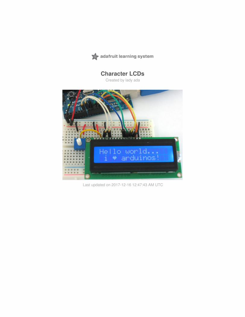
Character LCDsCreated by lady ada
Last updated on 2017-12-16 12:47:43 AM UTC

2346889
1113
1721
24262833
Guide Contents
Guide ContentsOverviewCharacter vs. Graphical LCDsLCD VarietiesWiring a Character LCD
Installing the Header PinsPower and BacklightContrast CircuitBus Wiring
Arduino CodeMultiple Lines
RGB Backlit LCDsCircuitPython CodeUsageThe createChar Command
© Adafruit Industries https://learn.adafruit.com/character-lcds Page 2 of 33

OverviewWe sell tons of lovely character LCDs for use with Arduino, they are extremely common and a fast way to have yourproject show status messages. This tutorial will show how you can easily connect a character LCD, either 16x2 or 20x4.
The LCDs we sell at Adafruit have a low power LED backlight, run on +5v and require only 6 data pins to talk to. Youcan use any data pins you want!
This tutorial will cover character LCDs carried at Adafruit - such as our "standard" blue&white 16x2, RGB 16x2 LCDs,"standard" blue&white 20x4 and RGB 20x4. We don't guarantee it will work with any other LCDs. If you need helpgetting other LCDs to work, please contact the place you purchased it from, they'll be happy to help!
© Adafruit Industries https://learn.adafruit.com/character-lcds Page 3 of 33

Character vs. Graphical LCDsThere are hundreds of different kinds of LCDs, the ones we'll be covering here are character LCDs. Character LCDsare ideal for displaying text. They can also be configured to display small icons but the icons must be only 5x7 pixelsor so (very small!)
Here is an example of a character LCD, 16 characters by 2 lines:
If you look closely you can see the little rectangles where the characters are displayed. Each rectangle is a grid ofpixels. Compare this to a graphical LCD such as the following:
© Adafruit Industries https://learn.adafruit.com/character-lcds Page 4 of 33

The graphical LCD has one big grid of pixels (in this case 128x64 of them) - It can display text but its best at displayingimages. Graphical LCDs tend to be larger, more expensive, difficult to use and need many more pins because of thecomplexity added.
This tutorial isn't about graphical LCDs. Its only about text/character LCDs!
© Adafruit Industries https://learn.adafruit.com/character-lcds Page 5 of 33

LCD VarietiesOK now that we're clear about what type of LCD we're talking about, its time to also look at the different shapes theycome in.
Although they display only text, they do come in many shapes: from top left we have a 20x4 with white text on bluebackground, a 16x4 with black text on green, 16x2 with white text on blue and a 16x1 with black text on gray.
The good news is that all of these displays are 'swappable' - if you build your project with one you can unplug it anduse another size. Your code may have to adjust to the larger size but at least the wiring is the same!
For this part of the tutorial, we'll be using LCDs with a single strip of 16 pins as shown above. There are also some with2 lines of 8 pins like so:
© Adafruit Industries https://learn.adafruit.com/character-lcds Page 6 of 33

These are much harder to breadboard. If you want some help in wiring these up, check out this page.
© Adafruit Industries https://learn.adafruit.com/character-lcds Page 7 of 33

Wiring a Character LCD
Installing the Header Pins
OK now you've got your LCD, you'll also need a couple other things. First is a 10K potentiometer. This will let you adjustthe contrast. Each LCD will have slightly different contrast settings so you should try to get some sort of trimmer. You'llalso need some 0.1" header - 16 pins long.
If the header is too long, just cut/snap it short!
Next you'll need to solder the header to the LCD.You must do this, it is not OK to just try to 'press fit' the LCD!
Also watch out not to apply too much heat, or you may melt the underlying breadboard. You can try 'tacking' pin 1 and
© Adafruit Industries https://learn.adafruit.com/character-lcds Page 8 of 33

pin 16 and then removing from the breadboard to finish the remaining solder points
The easiest way we know of doing this is sticking the header into a breadboard and then sitting the LCD on top whilesoldering. this keeps it steady.
Power and Backlight
K now we're onto the interesting stuff! Get your LCD
plugged into the breadboard.
© Adafruit Industries https://learn.adafruit.com/character-lcds Page 9 of 33

Now we'll provide power to the breadboard. Connect
+5V to the red rail, and Ground to the blue rail.
Next we'll connect up the backlight for the LCD.
Connect pin 16 to ground and pin 15 to +5V. On the vast
majority of LCDs (including ones from Adafruit) the LCD
includes a series resistor for the LED backlight.
If you happen to have one that does not include a
resistor, you'll need to add one between 5V and pin 15.
To calculate the value of the series resistor, look up the
maximum backlight current and the typical backlight
voltage drop from the data sheet. Subtract the voltage
drop from 5 volts, then divide by the maximum current,
then round up to the next standard resistor value. For
example, if the backlight voltage drop is 3.5v typical and
the rated current is 16mA, then the resistor should be (5
- 3.5)/0.016 = 93.75 ohms, or 100 ohms when rounded
up to a standard value. If you can't find the data sheet,
then it should be safe to use a 220 ohm resistor,
although a value this high may make the backlight
rather dim.
© Adafruit Industries https://learn.adafruit.com/character-lcds Page 10 of 33

Connect the Arduino up to power, you'll notice the
backlight lights up.
Note that some low-cost LCDs dont come with a backlight. Obviously in this case you should just keep going.
Contrast Circuit
Next, lets place the contrast pot, it goes on the side near
pin 1.
Connect one side of the pot to +5V and the other to
Ground (it doesn't matter which goes on what side). The
middle of the pot (wiper) connects to pin 3 of the LCD.
© Adafruit Industries https://learn.adafruit.com/character-lcds Page 11 of 33

Now we'll wire up the logic of the LCD - this is seperate
from the backlight! Pin 1 is ground and pin 2 is +5V.
Now turn on the Arduino, you'll see the backlight light
up (if there is one), and you can also twist the pot to see
the first line of rectangles appear.
This means you've got the logic, backlight and contrast all worked out. Don't keep going unless you've got this figuredout!
Bus WiringNow we'll finish up the wiring by connecting the data lines. There are 11 bus lines: D0 through D7 (8 data lines)
© Adafruit Industries https://learn.adafruit.com/character-lcds Page 12 of 33

and RS, EN, and RW. D0-D7 are the pins that have the raw data we send to the display. TheRS pin lets themicrocontroller tell the LCD whether it wants to display that data (as in, an ASCII character) or whether it is a commandbyte (like, change posistion of the cursor). The EN pin is the 'enable' line we use this to tell the LCD when data is readyfor reading. The RW pin is used to set the direction - whether we want to write to the display (common) or read from it(less common)
The good news is that not all these pins are necessary for us to connect to the microcontroller (Arduino). RW forexample, is not needed if we're only writing to the display (which is the most common thing to do anyways) so we can'tie' it to ground. There is also a way to talk to the LCD using only 4 data pins instead of 8. This saves us 4 pins! Whywould you ever want to use 8 when you could use 4? We're not 100% sure but we think that in some cases its faster touse 8 - it takes twice as long to use 4 - and that speed is important. For us, the speed isn't so important so we'll savesome pins!
So to recap, we need 6 pins: RS, EN, D7, D6, D5, and D4 to talk to the LCD.
We'll be using the LiquidCrystal library to talk to the LCD so a lot of the annoying work of setting pins and such istaken care of. Another nice thing about this library is that you can use any Arduino pin to connect to the LCD pins. Soafter you go through this guide, you'll find it easy to swap around the pins if necessary
As mentioned, we'll not be using the RW pin, so we can
tie it go ground. That's pin 5 as shown here.
Next is the RS pin #4. We'll use a brown wire to connect
it to Arduino's digital pin #7.
© Adafruit Industries https://learn.adafruit.com/character-lcds Page 13 of 33
Next is the EN pin #6, we'll use a white wire to connect
it to Arduino digital #8.
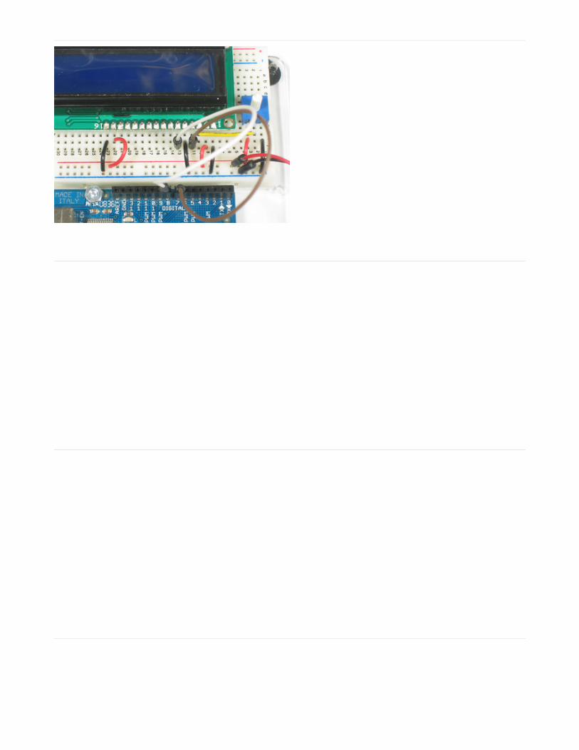
Now we will wire up the data pins. DB7 is pin #14 on the
LCD, and it connects with an orange wire to Arduino
#12.
Next are the remaining 3 data lines, DB6 (pin #13
yellow) DB5 (pin #12 green) and DB4 (pin #11 blue) which
we connect to Arduino #11, 10 and 9.
You should have four 'gap' pins on the LCD between
the 4 data bus wires and the control wires.
© Adafruit Industries https://learn.adafruit.com/character-lcds Page 14 of 33

This is what you'll have on your desk.
© Adafruit Industries https://learn.adafruit.com/character-lcds Page 15 of 33

Arduino CodeNow we must upload some sketch to the Arduino to talk to the LCD. Luckily the LiquidCrystal library is already built in.So we just need to load one of the examples and modify it for the pins we used.
If you've changed the pins, you'll want to make a handy table so you can update the sketch properly.
LCD pin name RS EN DB4 DB5 DB6 DB7
Arduino pin # 7 8 9 10 11 12
Open up the File→Examples→LiquidCrystal→HelloWorld example sketch
Now we'll need to update the pins. Look for this line:
And change it to:
To match the pin table we just made.
Now you can compile and upload the sketch.
LiquidCrystal lcd(12, 11, 5, 4, 3, 2);
LiquidCrystal lcd(7, 8, 9, 10, 11, 12);
© Adafruit Industries https://learn.adafruit.com/character-lcds Page 16 of 33

Adjust the contrast if necessary
© Adafruit Industries https://learn.adafruit.com/character-lcds Page 17 of 33

You can of course use any size or color LCD, such as a 20x4 LCD
Or a black on green
© Adafruit Industries https://learn.adafruit.com/character-lcds Page 18 of 33

The nice thing about the black on green ones is you can remove the backlight. Sometimes they dont come with one!
© Adafruit Industries https://learn.adafruit.com/character-lcds Page 19 of 33

Multiple LinesOne thing you'll want to watch for is how the LCD handles large messages and multiple lines. For example if youchanged this line:
To this:
The 16x2 LCD will cut off anything past the 16th character:
lcd.print("hello, world!");
lcd.print("hello, world! this is a long long message");
© Adafruit Industries https://learn.adafruit.com/character-lcds Page 20 of 33

But the 20x4 LCD will 'wrap' the first line to the third line! (Likewise the 2nd line runs into the 4th) This seems reallybizarre but its how the LCD memory configured on the inside. This probably should have been done differently but heythat's what we have to live with. Hopefully we'll have a future LCD library that is very smart and wraps lines but for nowwe are stuck. So when writing long lines to the LCD count your characters and make sure that you dont accidentallyoverrun the lines!
© Adafruit Industries https://learn.adafruit.com/character-lcds Page 21 of 33

© Adafruit Industries https://learn.adafruit.com/character-lcds Page 22 of 33

RGB Backlit LCDsWe now stock a few different RGB backlight LCDs . These LCDs work just like the normal character type, but thebacklight has three LEDS (red/green/blue) so you can generate any color you'd like. Very handy when you want tohave some ambient information conveyed.
After you've wired up the LCD and tested it as above, you can connect the LEDs to the PWM analog out pins of theArduino to precisely set the color. The PWM pins are fixed in hardware and there's 6 of them but three are alreadyused so we'll use the remaining three PWM pins. Connect the red LED (pin 16 of the LCD) to Digital 3, the green LEDpin (pin 17 of the LCD) to digital 5 and the blue LED pin (pin 18 of the LCD) to digital 6. You do not need any resistorsbetween the LED pins and the arduino pins because resistors are already soldered onto the character LCD for you!
Now upload this code to your Arduino to see the LCD background light swirl! (Click here to see what it looks like inaction).
// include the library code:#include <LiquidCrystal.h>#include <Wire.h> #define REDLITE 3#define GREENLITE 5#define BLUELITE 6 // initialize the library with the numbers of the interface pinsLiquidCrystal lcd(7, 8, 9, 10, 11, 12); // you can change the overall brightness by range 0 -> 255int brightness = 255; void setup() { // set up the LCD's number of rows and columns: lcd.begin(16, 2); // Print a message to the LCD.
© Adafruit Industries https://learn.adafruit.com/character-lcds Page 23 of 33

// Print a message to the LCD. lcd.print("RGB 16x2 Display "); lcd.setCursor(0,1); lcd.print(" Multicolor LCD "); pinMode(REDLITE, OUTPUT); pinMode(GREENLITE, OUTPUT); pinMode(BLUELITE, OUTPUT);
brightness = 100;} void loop() { for (int i = 0; i < 255; i++) { setBacklight(i, 0, 255-i); delay(5); } for (int i = 0; i < 255; i++) { setBacklight(255-i, i, 0); delay(5); } for (int i = 0; i < 255; i++) { setBacklight(0, 255-i, i); delay(5); }} void setBacklight(uint8_t r, uint8_t g, uint8_t b) { // normalize the red LED - its brighter than the rest! r = map(r, 0, 255, 0, 100); g = map(g, 0, 255, 0, 150); r = map(r, 0, 255, 0, brightness); g = map(g, 0, 255, 0, brightness); b = map(b, 0, 255, 0, brightness); // common anode so invert! r = map(r, 0, 255, 255, 0); g = map(g, 0, 255, 255, 0); b = map(b, 0, 255, 255, 0); Serial.print("R = "); Serial.print(r, DEC); Serial.print(" G = "); Serial.print(g, DEC); Serial.print(" B = "); Serial.println(b, DEC); analogWrite(REDLITE, r); analogWrite(GREENLITE, g); analogWrite(BLUELITE, b);}
© Adafruit Industries https://learn.adafruit.com/character-lcds Page 24 of 33

CircuitPython CodeIt's easy to use a character LCD with CircuitPython and the Adafruit CircuitPython CharLCD module. This moduleallows you to easily write Python code that controls a character LCD (either single backlight or RGB backlight).
First wire up a character LCD to your board exactly as shown on the previous pages for Arduino using the LCD'sparallel data bus. Here's an example of wiring a Metro M0 Express to a single color backlight character LCD:
Board 5V to LCD pin 2, 15, and one side of the potentiometer.Board GND to LCD pin 1, 5, 16, and the opposite side of the potentiometer.Potentiometer output (middle pin) to LCD pin 3Board D7 to LCD pin 4Board D8 to LCD pin 6Board D9 to LCD pin 11Board D10 to LCD pin 12Board D11 to LCD pin 13Board D12 to LCD pin 14
Remember just like the Arduino wiring page mentions there are 4 unused pins on the LCD, pins 7-10.
If you're using a RGB backlight here's an example of wiring it to your board. Remember each of the red, green, bluecolor channels needs to be wired to a PWM-capable output pin on your board (look for a dot next to the pin number onthe board typically):
© Adafruit Industries https://learn.adafruit.com/character-lcds Page 25 of 33

Board 5V to LCD pin 2, 15, and one side of the potentiometer.Board GND to LCD pin 1, 5, and the opposite side of the potentiometer.Potentiometer output (middle pin) to LCD pin 3Board D7 to LCD pin 4Board D8 to LCD pin 6Board D9 to LCD pin 11Board D10 to LCD pin 12Board D11 to LCD pin 13Board D12 to LCD pin 14Board D3 to LCD pin 16 (red backlight)Board D5 to LCD pin 17 (green backlight)Board D6 to LCD pin 18 (blue backlight)
Next you'll need to install the Adafruit CircuitPython CharLCD library on your CircuitPython board. Remember thismodule is for Adafruit CircuitPython firmware and not MicroPython.org firmware!
First make sure you are running the latest version of Adafruit CircuitPython for your board.
Next you'll need to install the necessary libraries to use the hardware--carefully follow the steps to find and install theselibraries from Adafruit's CircuitPython library bundle. For example the Circuit Playground Express guide has a greatpage on how to install the library bundle for both express and non-express boards.
Remember for non-express boards like the Trinket M0, Gemma M0, and Feather/Metro M0 basic you'll need tomanually install the necessary libraries from the bundle:
adafruit_character_lcd
You can also download the adafruit_character_lcd from its releases page on Github.
Before continuing make sure your board's lib folder or root filesystem has the adafruit_character_lcd folder copiedover.
Next connect to the board's serial REPL so you are at the CircuitPython >>> prompt.
© Adafruit Industries https://learn.adafruit.com/character-lcds Page 26 of 33

Usage
To demonstrate the usage of the character LCD we'll initialize it and write text using Python code.
First you need to import the digitalio module and define all the pins connected to the LCD. If you followed the wiringfor a single color backlight display on this page you'd want to use:
Or for a RGB backlight you need to import both the digitalio and pulseio modules and create the extra PWM lines. Forexample with the wiring on this page:
Now define the size of your character LCD in number of columns and rows, for example for a 16 character wide by 2row tall display:
Next import the character LCD module and create an instance of the Character_LCD or Character_LCD_RGB classdepending on what type of display you have wired up. For example for the single color backlight display:
Or for a RGB backlight display:
import boardimport digitaliolcd_rs = digitalio.DigitalInOut(board.D7)lcd_en = digitalio.DigitalInOut(board.D8)lcd_d7 = digitalio.DigitalInOut(board.D12)lcd_d6 = digitalio.DigitalInOut(board.D11)lcd_d5 = digitalio.DigitalInOut(board.D10)lcd_d4 = digitalio.DigitalInOut(board.D9)
import boardimport digitalioimport pulseiolcd_rs = digitalio.DigitalInOut(board.D7)lcd_en = digitalio.DigitalInOut(board.D8)lcd_d7 = digitalio.DigitalInOut(board.D12)lcd_d6 = digitalio.DigitalInOut(board.D11)lcd_d5 = digitalio.DigitalInOut(board.D10)lcd_d4 = digitalio.DigitalInOut(board.D9)red = pulseio.PWMOut(board.D3)green = pulseio.PWMOut(board.D5)blue = pulseio.PWMOut(board.D6)
lcd_columns = 16lcd_rows = 2
import adafruit_character_lcdlcd = adafruit_character_lcd.Character_LCD(lcd_rs, lcd_en, lcd_d4, lcd_d5, lcd_d6, lcd_d7, lcd_columns, lcd_rows
import adafruit_character_lcdlcd = adafruit_character_lcd.Character_LCD_RGB(lcd_rs, lcd_en, lcd_d4, lcd_d5, lcd_d6, lcd_d7, lcd_columns
© Adafruit Industries https://learn.adafruit.com/character-lcds Page 27 of 33

Now you can print a message using the message function, for example to print on two lines (notice the \n line breakadded to the string in the middle):
You can turn the cursor on and off using the show_cursor function. Pass True to turn it on and False to turn it off, forexample to turn on:
And to turn off:
You can clear the entire display using the clear function:
lcd.message('Hello\nCircuitPython!')
lcd.show_cursor(True)
lcd.show_cursor(False)
© Adafruit Industries https://learn.adafruit.com/character-lcds Page 28 of 33

You can also blink the cursor by turning it on and then calling the blink function with a boolean value. (Note the RGBdisplay class does not currently support this function). A value of True will start blinking the cursor, and False willdisable blinking. For example to print a message and blink the cursor:
Finally the move_left message will move the printed message one character left, like if you wanted to scroll it off thescreen. Try it:
lcd.clear()
lcd.show_cursor(True)lcd.blink(True)lcd.message('Blink!')
lcd.move_left()
© Adafruit Industries https://learn.adafruit.com/character-lcds Page 29 of 33

Or call move_right to scroll a character back to the right:
If you're using the RGB backlight display there's one extra function you can use to change the backlight color. Use theset_color function and pass a 3-tuple of red, green, blue color values that range from 0 to 100. For example to set thecolor to red:
Or to green:
lcd.move_right()
lcd.set_color((100, 0, 0))
lcd.set_color((0, 100, 0))
© Adafruit Industries https://learn.adafruit.com/character-lcds Page 30 of 33

Or to blue:
Or any color in between, like a pleasing warm white with full red, nearly full green, and half blue:
That's all there is to using a character LCD with CircuitPython! Be sure to see the examples in the character LCDlibrary too for more fun like creating and printing custom characters.
lcd.set_color((0, 0, 100))
lcd.set_color((100, 80, 50))
© Adafruit Industries https://learn.adafruit.com/character-lcds Page 31 of 33

The createChar CommandYou may want to have special characters, for example in this temperature sensor, we created a 'degree' symbol (°)
You can do that with the createChar command, and to help you out we're going to point you to this really greatwebsite that does the hard work for you!
© Adafruit Industries https://learn.adafruit.com/character-lcds Page 32 of 33