Embed Size (px)
Citation preview
581
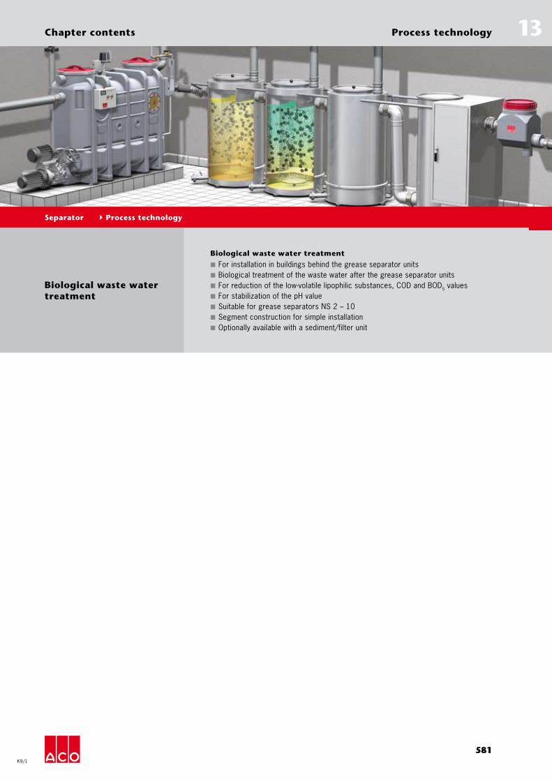
Biological waste water treatment
Biological waste water treatment
For installation in buildings behind the grease separator units ■
Biological treatment of the waste water after the grease separator units ■
For reduction of the low-volatile lipophilic substances, COD and BOD ■ 5 valuesFor stabilization of the pH value ■
Suitable for grease separators NS 2 – 10 ■
Segment construction for simple installation ■
Optionally available with a sediment/filter unit ■
581
13
K9/1
Process technology
Separator Process technology
Chapter contents

PageBasics 584Planing information 584
Biology Waste water treatment plant
ACO Biojet 586
ACO Biojet-F 588
Filter technology Secondary cleaning stage Sedimentation/filtration unit 590
Separator Process technology Biology/filter technology

PageBasics 584Planing information 584
Biology Waste water treatment plant
ACO Biojet 586
ACO Biojet-F 588
Filter technology Secondary cleaning stage Sedimentation/filtration unit 590
583583
Pro
cess
tec
hn
olo
gy
Bio
log
y/fi
lter
tec
hn
olo
gy
13
K9/1
Biological waste water treatment
Separator Process technology Biology/filter technology
Section contents

584
Pro
cess
tec
hn
olo
gy
Bio
log
y/fi
lter
tec
hn
olo
gy
13
K9/1
Process technologyPlanning references
Separator Process technology Biology/filter technology
Basics
Continued waste water treatment
Special requirements are placed on the further treatment of waste water, since waste water can be made up differently depending on the process technology. the most important aspects, such as process engineering, economics and ecology were included in the design of
the waste water treatment facilities. Only after a sound analysis of the respective local conditions and the exact waste water conditions can be decided, which method represents the best solution for the spe-cific application. ACO offers equipment and process
technologies for this, with which the most diverse tasks in waste water treatment can be solved when applied properly.
Application scope
Oily waste water from commercial ■
kitchens
Overview of the process technology for the continued waste water treatment
Biological waste water treatment
Treatment, waste water polluted with organic with animal and vegetable oils and fats
Sedimentation/filtration unit ■
Standard biology or ■
combination of standard biology and ■
sedimentation/filtration unit
Planning information
Application
The biological waste water treatment is an especially environmentally friendly applica-tion technique. The great organic pollution of waste water with oils and greases from the kitchen sector reequires the use of a grease separator according applicable regulations. The waste water is treated solely by gravity in these separation facili-ties. However, only the clearly separable oils and greases as well as settleable solids are generally retained. Emulsified and dissolved components in the waste water
pass the separator almost unchecked. This inevitably leads to exceeding the limit values at increased demands on the param-eter of lipophilic substances. Since these parameters in many cities (eg Frankfurt) are increasingly in view of the authorities, the focus is on further purification processes after the separator facility.
The limit for the compliance with low-volatile lipophilic substances is permanently met with the standard biology ACO Biojet and/or the ACO sedimentation/filtration unit developed by ACO. Furthermore, the param-eters if COD and BOD 5, the pH value, and the deposable substances are effectively reduced.

585
Pro
cess
tec
hn
olo
gy
Bio
log
y/fi
lter
tec
hn
olo
gy
13
K9/1
Process technologyPlanning references
Separator Process technology Biology/filter technology
Function description of the ACO sedimentation/filtration unit
The ACO sedimentation/filtration unit con-sists of a filter case and a transfer unit. The pre-treated waste water in the grease separator flows to the filter case in a free fall. A pump arranged in the transfer unit suctions the waste water through the filter cartridge unit after it reaches a certain level into the drain pipe to the sewer. The sedimentation/filtration unit retains the smallest grease particles and suspended solids in the filter case. Air is routinely blown into the interior of the filter car-
tridge between the reduction phase into the sewer. The air cleans the filter surface from the inside out. The residue that ac-cumulated in the filter case is transported in regular intervals into the intake of the grease separator by the pump.
Product advantages
complete system technology of stain- ■
less steel, material grade 316sealed against odours ■
completely automatic operation ■
no additional dosing of fissionable ■
chemicals or or operating equipment is requiredeasiest insertion based on the segment ■
construction method
Function description of standard biology ACO Biojet
The standard biology consists of several biological reactors and a transfer station. The pre-cleaned waste water in the grease separator flows to the bioreactor in a free fall. It is channeled into the lower area of the reactor by a suitably shaped supply channel. From there, the waste water reaches through the special fluidised biol-ogy. The micro-organisms located in this fluidised bed treat the organically polluted waste water. The emulsified and dissolved organic particles are effectively reduced. The waste water now continues to flow into the transfer station. The overflow
edge arranged before the drain maintains the water lever and pulls the waste water rom the surface. This then drains in a free fall into the drain pipe to the sewer. The sedimentable particles still located in the waste water sink to the floor in the transfer station and are channeled into the intake of the standard biology by a pump and again channeled to the reduction proc-ess as active biomass.
Product advantages
complete system technology of stain- ■
less steel, material grade 316sealed against odours ■
completely automatic operation ■
minor subsequent costs for operating ■
equipmenteasiest insertion based on the segment ■
construction method
The following combinations are possible
Version 1: Grease separator according to EN 1825/DIN 4040-100 + sedimentation/filtration unit
Version 2: Grease separator according to EN 1825/DIN 4040-100 + standard biology
Version 3: Grease separator according to EN 1825/DIN 4040-100 +standard biology + sedimentation/filtration unit
Reduction of lipophilic substances
The diagram on the right provides an overview how the parameter of low-volatile lipophilic substances is reduced by using these combinations. The lipophilic substances are thereby com-bined of the following organic parts:
Clearly separable lipophilic parts ■
Slow-evaporating lipophilic components ■
ACO
sepa
rato
r sys
tem
s
Untreated
1
2
3
4
1 Grease separator 2 grease separator+ sedimentation/
filtration unit
3 Grease separator+ biology
4 Grease separator + biology + sedimentation/filtration unit
low-volatile lipophilic substances in mg/I
300200
0
up to 100
up to 50 %
up to 20 %

586
Pro
cess
tec
hn
olo
gy
Bio
log
y/fi
lter
tec
hn
olo
gy
13
K9/1
Biology
Separator Process technology Biology/filter technology
Waste water treatment plant ACO Biojet
Product information
ACO product advantages
Reduction of the low-volatile lipophilic ■
substances to c. 100 mg/l after biolo-gical treatmentThe bio-chemical process stabilizes ■
the pH value in a neutral areaBio-chemical processes ensure conti- ■
nued reduction of the BOD5 and COD load of the waste waterNo residue which needs to be perma- ■
nently disposed ofLow personnel and maintenance ■
requirementsFollow-up costs only as energy costs ■
for the pump technology and working agentsProblem-free installation of the plant ■
components through the modular principle:The microorganism strains used do ■
not present a risk for health and environment
Biological waste water treatment behind ■
the grease separator in accordance with EN 1825/DIN 4040-100 for NS (2/4/7/10)Energy-saving and user-friendly automa- ■
tic designFor significant reduction of the low- �
volatile lipophilic substancesFor significant reduction of the COD �
and BOD5 valuesFor stabilization of the pH value �
For free-standing installation in rooms ■
Stainless steel, material grade 316 ■
Plant enclosed air-tight ■
In segment/modular design (extendable) ■
Biological containers and a sedimenta- ■
tion unitMaintenance-friendly and economical �
plant technologyWith fluidised bed biology and �
specially adapted micro-organisms (group I of non-pathogen strains)With automatic sediment re-circulati- �
on from the sedimentation unit in the plant (re-circulation pump/delivery flow: 12 m³/h)Draw-off of the cleaned waste water �
in the canalWith standard control IP 55 with �
automatic program sequence and centralised fault signal for the ZLT (GLT)With scour plug DN 100 for revision �
purposesSystem ACO Passavant ■
Inlet and drainage DN 150 �
Connection port with an external �
diameter: 160 mm (transfer loosely added at NS 2/4)Separate plant ventilation �
Connection port on the biology reac- �
tors with external diameter: 110 mmElectrical connection: �
230 V/50 Hz/0.8 kWNecessary air quantity: 3 times the �
room volume per hour
Ordering information
Type Number of bioreactors
Capacity bioreactor
Total capa-city
Weight Article No.
Empty Full Right Left[l] [l] [kg] [kg]
2 2 500 1000 450 1442 7902.00.00 7902.00.104 3 500 1500 600 2050 7904.00.00 7904.00.107 6 570 3420 1160 4500 7907.00.00 7907.00.10
10 8 570 4560 1600 6600 7910.00.00 7910.00.10

587
Pro
cess
tec
hn
olo
gy
Bio
log
y/fi
lter
tec
hn
olo
gy
13
K9/1
Biology
Separator Process technology Biology/filter technology
Remark: Other versions on request.
Infobox
Dimensions
inletDN...
outlet DN...
bioreactor
maintenance opening ventilation DN 100
H 2
H 3
H 1
operation space
bioreactor
n x Ø 750
900
Ø 500
min
600
Ø 750
B
A
820
ca. 6
00m
in 1
50
80
control
sediment backflow line
compressed air supply line
maintenanceopening
filtercontainer
power unit
Type DimensionsH1 H2 H3 A B
[mm] [mm] [mm] [mm] [mm]2 1120 1070 1450 3100 9004 1120 1070 1450 4100 9007 1290 1240 1630 4600 3700
10 1470 1420 1820 5500 4600
588
Pro
cess
tec
hn
olo
gy
Bio
log
y/fi
lter
tec
hn
olo
gy
13
K9/1
Biology
Separator Process technology Biology/filter technology
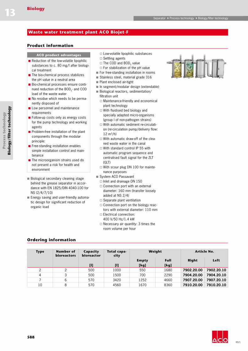
Waste water treatment plant ACO Biojet-F
Product information
ACO product advantages
Reduction of the low-volatile lipophilic ■
substances to c. 80 mg/l after biologi-cal treatmentThe bio-chemical process stabilizes ■
the pH value in a neutral areaBio-chemical processes ensure conti- ■
nued reduction of the BOD5- and COD load of the waste waterNo residue which needs to be perma- ■
nently disposed ofLow personnel and maintenance ■
requirementsFollow-up costs only as energy costs ■
for the pump technology and working agentsProblem-free installation of the plant ■
components through the modular principle:Free-standing installation enables ■
simple installation control and main-tenanceThe microorganism strains used do ■
not present a risk for health and environment
Biological secondary cleaning stage ■
behind the grease separator in accor-dance with EN 1825/DIN 4040-100 for NS (2/4/7/10)Energy saving and user-friendly automa- ■
tic design for significant reduction of organic load
Low-volatile lipophilic substances �
Settling agents �
The COD and BOD � 5 valueFor stabilization of the pH value �
For free-standing installation in rooms ■
Stainless steel, material grade 316 ■
Plant enclosed air-tight ■
In segment/modular design (extendable) ■
Biological reactors, sedimentation/ ■
filtration unitMaintenance-friendly and economical �
plant technologyWith fluidised bed biology and �
specially adapted micro-organisms (group I of non-pathogen strains)With automatic sediment re-circulati- �
on (re-circulation pump/delivery flow: 12 m³/h)With automatic draw-off of the clea- �
ned waste water in the canalWith standard control IP 55 with �
automatic program sequence and centralised fault signal for the ZLT (GLT)With scour plug DN 100 for mainte- �
nance purposesSystem ACO Passavant ■
Inlet and drainage DN 150 �
Connection port with an external �
diameter: 160 mm (transfer loosely added at NS 2/4)Separate plant ventilation �
Connection port on the biology reac- �
tors with external diameter: 110 mmElectrical connection: �
400 V/50 Hz/1.4 kWNecessary air quantity: 3 times the �
room volume per hour
Ordering information
Type Number of bioreactors
Capacity bioreactor
Total capa-city
Weight Article No.
Empty Full Right Left[l] [l] [kg] [kg]
2 2 500 1000 550 1680 7902.20.00 7902.20.104 3 500 1500 700 2290 7904.20.00 7904.20.107 6 570 3420 1252 4660 7907.20.00 7907.20.10
10 8 570 4560 1670 8360 7910.20.00 7910.20.10

589
Pro
cess
tec
hn
olo
gy
Bio
log
y/fi
lter
tec
hn
olo
gy
13
K9/1
Biology
Separator Process technology Biology/filter technology
Remark: Other versions on request.
Infobox
Dimensions
inletDN...
outlet DN...
bioreactor
maintenance opening ventilation DN 100
H 2
H 3
H 1
operation space
bioreactor
n x Ø 750
900
Ø 500
min
600
Ø 750
B
A
820
ca. 6
00m
in 1
50
80
control
sediment backflow line
compressed air supply line
maintenanceopening
filtercontainer
power unit
Type DimensionsH1 H2 H3 A B
[mm] [mm] [mm] [mm] [mm]2 1120 1070 1450 3400 9204 1120 1070 1450 4500 9207 1290 1070 1650 4950 3700
10 1470 1070 1800 5900 4600

590
Pro
cess
tec
hn
olo
gy
Bio
log
y/fi
lter
tec
hn
olo
gy
13
K9/1
Filter technology
Separator Process technology Biology/filter technology
Sedimentation/filtration unit
Product information
ACO product advantages
Reduction of the boundary value of ■
lipophilic substances to c. 150 – 200 mg/l after the filterThe entire plant technology is enclo- ■
sed air-tightNo addition of splitting chemicals or ■
working agents necessaryNo residue which needs to be perma- ■
nently disposed ofMinimal personnel and maintenance ■
requirementsSubsequent costs only as energy ■
costs for the pump technologyProblem-free installation of the plant ■
components through the modular principle:Free-standing installation enables ■
simple installation control and main-tenance
ACO sedimentation/filtration unit secon- ■
dary cleaning stage behind the ACO Bio-jet (biological secondary cleaning stage)
and/or ACO grease separators in accor-dance with EN 1825/DIN 4040-100 for NS (2/4/7/10)Energy-saving and user-friendly automa- ■
tic designFor significant reduction of settling �
and filtratable agentsFor significant reduction of the COD �
and BOD5 valuesFor free-standing installation in rooms ■
Stainless steel, material grade 316 ■
Plant enclosed air-tight in segment ■
constructionMaintenance-friendly and economical �
plant technologyWith automatic sediment re-circulati- �
on (re-circulation pump/delivery flow: 12 m³/h)With automatic draw-off of the filtered �
waste water in the canalWith standard control IP 55 with �
automatic program sequence and centralised fault signal for the ZLT (GLT)
Ordering information
Type Total capacity Heaviest individual component
Weight Article No.
Right Left[l] [kg] [kg]
2 220 70 230 7902.10.00 7902.10.104 220 70 230 7904.10.00 7904.10.107 255 70 230 7907.10.00 7907.10.10
10 290 70 230 7910.10.00 7910.10.10

591
Pro
cess
tec
hn
olo
gy
Bio
log
y/fi
lter
tec
hn
olo
gy
13
K9/1
Filter technology
Separator Process technology Biology/filter technology
Dimensions
H 3
outlet DN150
H 2H1
operation space
900
ca. 6
00m
in 1
50
control
maintenanceopening
filtercontainer
power unit
inletDN150
1500
connectionsediment backflow
inlet compressed air
Type DimensionsH1 H2 H3
[mm] [mm] [mm]2 1120 1070 14504 1120 1070 14507 1290 1070 1450
10 1470 1070 1450