Embed Size (px)
Citation preview

Chapter 9Ethernet – Part 1
CIS 82 Routing Protocols and Concepts
Rick Graziani
Cabrillo College
Last Updated: Fall 2009

2
Note to instructors If you have downloaded this presentation from the Cisco Networking Academy
Community FTP Center, this may not be my latest version of this PowerPoint. For the latest PowerPoints for all my CCNA, CCNP, and Wireless classes,
please go to my web site:
http://www.cabrillo.edu/~rgraziani/ The username is cisco and the password is perlman for all of my
materials. If you have any questions on any of my materials or the curriculum, please feel
free to email me at [email protected] (I really don’t mind helping.) Also, if you run across any typos or errors in my presentations, please let me know.
I will add “(Updated – date)” next to each presentation on my web site that has been updated since these have been uploaded to the FTP center.
Thanks! Rick
3
Ethernet Fundamentals
Part 1 Introduction to Ethernet
Part 2 Layer 2 and Ethernet Switches Cables, Duplex, and Troubleshooting Ethernet and the OSI Model – more detail Ethernet frames – more detail

Introduction to Ethernet

5
Ethernet Local Area Networks (LANs)
LAN (Local Area Network) - A computer network connected through a wired or wireless medium by networking devices (hubs, switches, routers) and administered by a single organization.
Ethernet – A family of Layer 2 Data Link protocols for Local Area Networks .

6
IEEE Standards
Brief History: 1970’s - Robert Metcalfe and his coworkers at Xerox PARC 1980 - Ethernet protocol published by Digital Equipment
Corporation, Intel, and Xerox (DIX) 1985 - Institute of Electrical and Electronics Engineers (IEEE)
published IEEE 802.2 and 802.3

7
LLC (Logical Link Control)LLC (Logical Link Control)
MAC (Media Access Control)MAC (Media Access Control)
IEEE 802 Extension to the OSI Model
Data Link Sublayers
The Institute of Electrical and Electronic Engineers (IEEE) is a professional organization that defines network standards.
IEEE 802.3 “Ethernet” is the predominant and best known LAN standards, along with 802.11 (WLAN).
The IEEE divides the OSI data link layer into two separate sublayers. Recognized IEEE sublayers are:
Media Access Control (MAC) (transitions down to media) Logical Link Control (LLC) (transitions up to the network layer)

8
LLC – Logical Link Sublayer
Logical Link Control (LLC) defined in the IEEE 802.2 specification Provides versatility in services to network layer protocols that are above
it, while communicating effectively with the variety of technologies below it.
The LLC, as a sublayer, participates in the encapsulation process.

9
802.2 LLC
IPX IP APPLE-TALK
LLC
Layer 3Layer 3
Layer 2 - LLCLayer 2 - LLC
MAC &Layer 1MAC &Layer 1 Ethernet Token Ring
FDDI* *
**
* Legacy technologies

10
Application Header + data
802.2 LLC Data Encapsulation Example
We have been focusing on the Layer 2, Data Link, Ethernet Frame for now.
010010100100100100111010010001101000…
Application Layer
Layer 4: Transport Layer
Layer 3: Network Layer
Layer 2: Data Link Layer
Layer 1: Physical Layer

11
MAC – Media Access Control Sublayer
The Media Access Control (MAC) sublayer deals with the protocols that a host follows in order to access the physical media.
Defined in IEEE 802.3 specification Responsible for the actual framing
Builds the 1s and 0s to hand off to the physical layer. Responsible for media access (CSMA/CD)

12
The IEEE Working Groups
802.1
802.2
802.3
802.4
802.5
802.6
802.7
802.8
802.9
Networking Overview and Architecture
Logical Link Control
Ethernet
Token Bus
Token Ring
MANs
Broadband
Fiber Optic
Isochronous LAN
...and more!
802.11 Wireless LAN

13
Network Interface Card (NIC)

14
Network Interface Card (NIC)
Network Interface Card (NIC) Layer 2, Data Link Layer, device Connects the device (computer) to the LAN Responsible for the local Layer 2 address (later) Common Layer 2 NICs:
Ethernet Token Ring
Common Bandwidth 10 Mbps, 10/100 Mbps, 10/100/1000 Mbps

15
Tracing the Physical Connection NIC (Network Interface Card)

16
Connecting the NIC to a Hub or Switch…

17
From PC to Ethernet Port…

18
From Ethernet Port to Patch Panel…
Back View Front View

19
From Patch Panel to Switch (or hub)

20
From PC to Switch

21
All of that is the same as these!

22
Our focus!
Ethernet protocol is only concerned with how the information gets from one Ethernet host or device to another.

23
Ethernet and IEEE 802.3
This standard includes the protocol used to “frame” the data by the sending Ethernet host computer.
Most of the time, the term “Ethernet” is used to mean IEEE 802.3 Ethernet and IEEE 802.3 are used interchangeably, even though they
are not really the same thing. (more later)
24
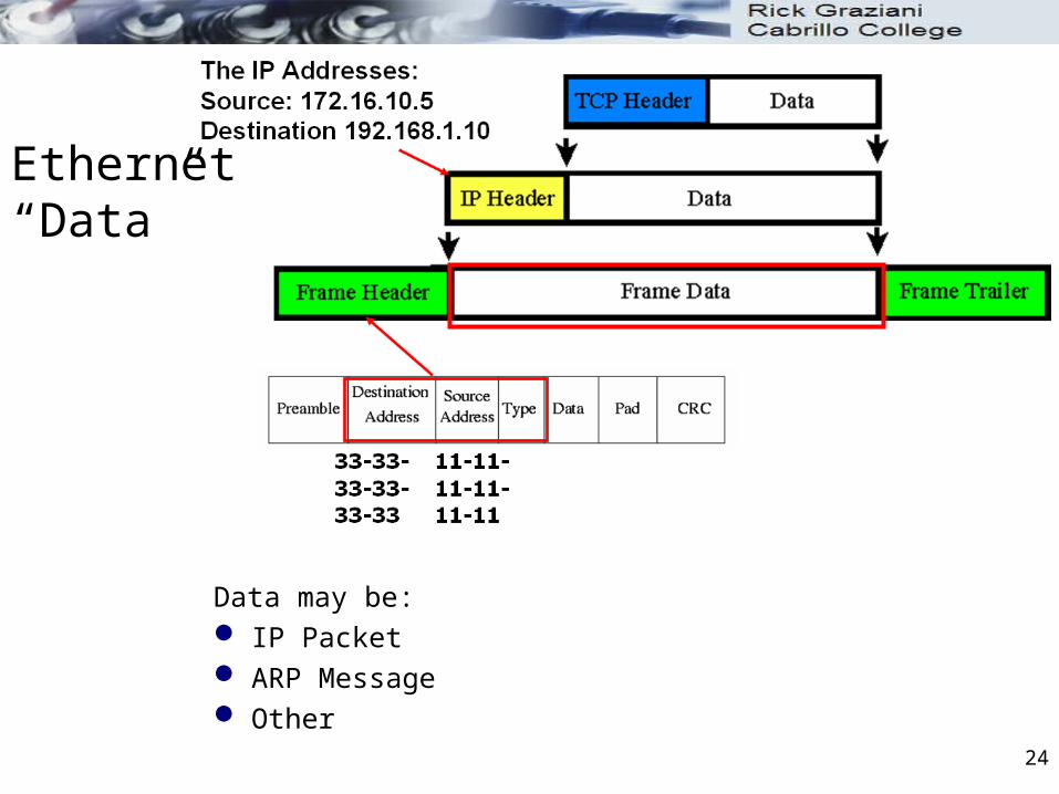
Data may be: IP Packet ARP Message Other
Ethernet “Data”

25
The MAC Address
Part of the Ethernet protocol includes the MAC (Media Access Control) - coming
Every Ethernet NIC card has a unique MAC address. MAC addresses provide a way for computers to identify themselves. They give hosts a permanent, unique name.

26
The MAC Address
MAC addresses are: 48 bits in length Expressed as 12 hexadecimal digits. The first 6 hexadecimal digits, which are administered by the IEEE,
identify the manufacturer or vendor and thus comprise the Organizational Unique Identifier (OUI).
The remaining 6 hexadecimal digits comprise the interface serial number, or another value administered by the specific vendor.
MAC addresses are sometimes referred to as burned-in addresses (BIAs) because they are burned into read-only memory (ROM) and are copied into random-access memory (RAM) when the NIC initializes
27
The MAC Address
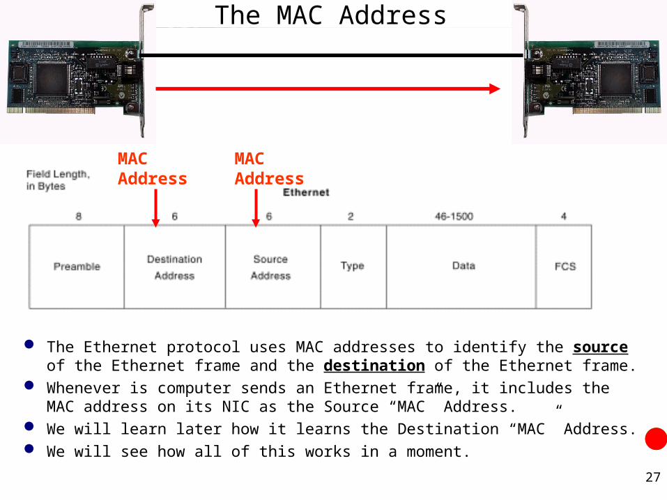
The Ethernet protocol uses MAC addresses to identify the source of the Ethernet frame and the destination of the Ethernet frame.
Whenever is computer sends an Ethernet frame, it includes the MAC address on its NIC as the Source “MAC” Address.
We will learn later how it learns the Destination “MAC” Address. We will see how all of this works in a moment.
MAC Address
MAC Address

28
Decimal, Binary, Hex
8
9
A
B
C
D
E
F
Dec Bin Hex Dec Bin Hex0 = 0000 = 0 8 = 1000 = 81 = 0001 = 1 9 = 1001 = 92 = 0010 = 2 10 = 1010 = A3 = 0011 = 3 11 = 1011 = B4 = 0100 = 4 12 = 1100 = C5 = 0101 = 5 13 = 1101 = D6 = 0110 = 6 14 = 1110 = E7 = 0111 = 7 15 = 1111 = F

29
MAC Address Format
OUI unique An Intel MAC address: 00-20-E0-6B-17-62 0000 0000 - 0010 0000 – 1110 0000 - 0110 1011 – 0001 0111 – 0110 0010 IEEE OUI FAQs: http://standards.ieee.org/faqs/OUI.html
Dec Bin Hex Dec Bin Hex0 = 0000 = 0 8 = 1000 = 81 = 0001 = 1 9 = 1001 = 92 = 0010 = 2 10 = 1010 = A3 = 0011 = 3 11 = 1011 = B4 = 0100 = 4 12 = 1100 = C5 = 0101 = 5 13 = 1101 = D6 = 0110 = 6 14 = 1110 = E7 = 0111 = 7 15 = 1111 = F
30
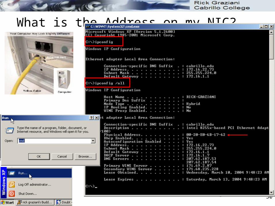
What is the Address on my NIC?

31
MAC Addresses Are Flat
MAC addresses provide a way for computers to identify themselves. They give hosts a permanent, unique name. The number of possible MAC addresses is 16^12 (or over 2 trillion!). MAC addresses do have one major disadvantage:
They have no structure, and is considered flat address space. Like using just a name when sending a letter instead of a structured
address.
32
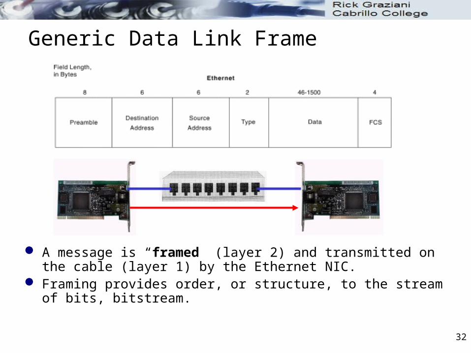
Generic Data Link Frame
A message is “framed” (layer 2) and transmitted on the cable (layer 1) by the Ethernet NIC.
Framing provides order, or structure, to the stream of bits, bitstream.

33
Bringing it all together…
Let’s pause here for a moment and figure all of this out!
Let’s bring the following together: Ethernet Frames and MAC Addresses Sending and receiving Ethernet frames on a bus CSMA/CD Sending and receiving Ethernet frames via a hub Sending and receiving Ethernet frames via a switch

34
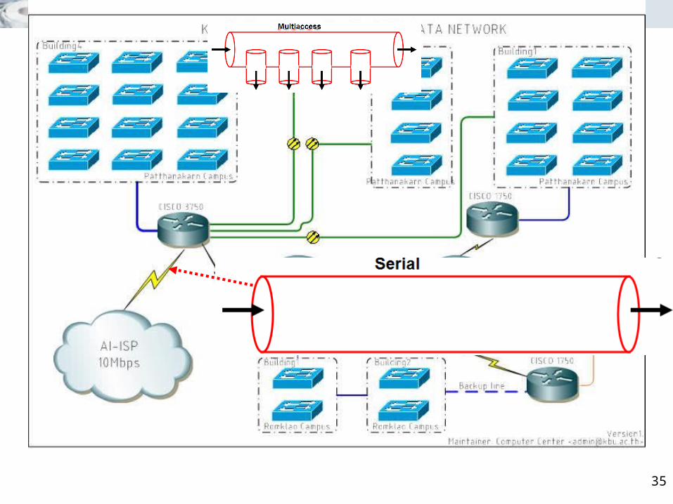
Serial vs Multiaccess NetworkSerial
Multiaccess
35

36
Ethernet: Multiaccess Network
37
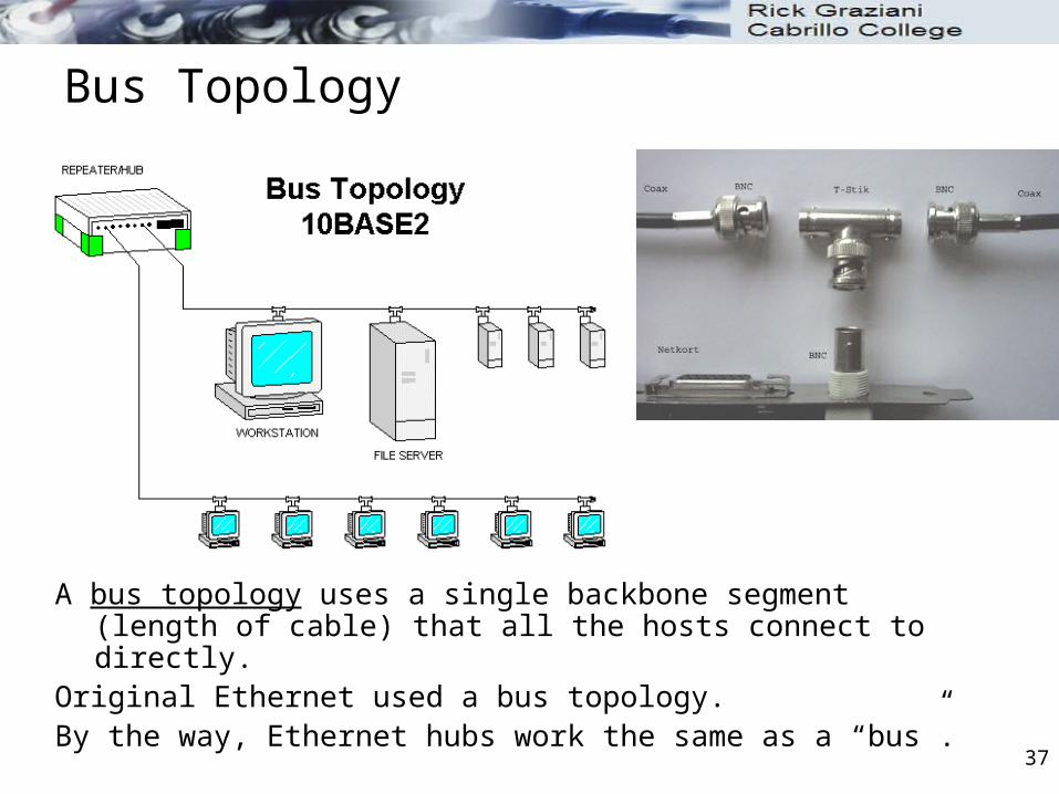
Bus Topology
A bus topology uses a single backbone segment (length of cable) that all the hosts connect to directly.
Original Ethernet used a bus topology.By the way, Ethernet hubs work the same as a “bus”.

38
Sending and receiving Ethernet frames on a bus
When an Ethernet frame is sent out on the “bus” all devices on the bus receive it.
What do they do with it?
1111 2222 3333 nnnn Abbreviated MAC Addresses
11113333

39
Sending and receiving Ethernet frames on a bus
When information (frame) is transmitted, every PC/NIC on the shared media copies part of the transmitted frame to see if the destination address matches the address of the NIC.
If there is a match, the rest of the frame is copied If there is NOT a match the rest of the frame is ignored.
Unless you are running a protocol analyzer program such as Ethereal.
1111 2222 3333 nnnn Abbreviated MAC Addresses
11113333
Nope
Nope
Hey, that’s me!

40
Sending and receiving Ethernet frames on a bus
So, what happens when multiple computers try to transmit at the same time?
1111 2222 3333 nnnn Abbreviated MAC Addresses

41
Sending and receiving Ethernet frames on a bus
Collision!
1111 2222 3333 nnnn Abbreviated MAC Addresses
X

42
Two common types of access methods for LANs include Non-Deterministic: Contention methods (Ethernet, IEEE
802.3)
Only one signal can be on a network segment at one time.
Collisions are a normal occurrence on an Ethernet/802.3 LAN
Deterministic: Token Passing (Token Ring) more later
Access Methods

43
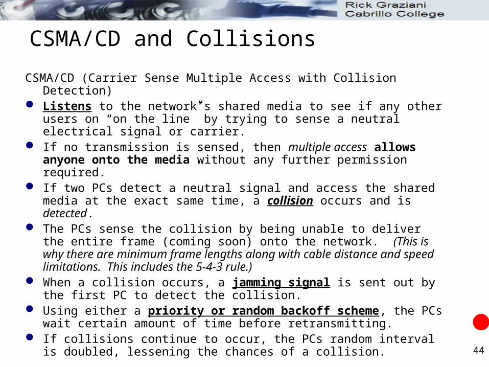
CSMA/CD (Carrier Sense Multiple Access with Collision Detection)
CSMA/CD Common contention method used with Ethernet and IEEE 802.3
“Let everyone have access whenever they want and we will work it out somehow.”
44
CSMA/CD (Carrier Sense Multiple Access with Collision Detection) Listens to the network’s shared media to see if any other users on “on the
line” by trying to sense a neutral electrical signal or carrier. If no transmission is sensed, then multiple access allows anyone onto
the media without any further permission required. If two PCs detect a neutral signal and access the shared media at the
exact same time, a collision occurs and is detected. The PCs sense the collision by being unable to deliver the entire frame
(coming soon) onto the network. (This is why there are minimum frame lengths along with cable distance and speed limitations. This includes the 5-4-3 rule.)
When a collision occurs, a jamming signal is sent out by the first PC to detect the collision.
Using either a priority or random backoff scheme, the PCs wait certain amount of time before retransmitting.
If collisions continue to occur, the PCs random interval is doubled, lessening the chances of a collision.
CSMA/CD and Collisions

45
And as we said, When information (frame) is transmitted, every PC/NIC on the shared
media copies part of the transmitted frame to see if the destination address matches the address of the NIC.
If there is a match, the rest of the frame is copied If there is NOT a match the rest of the frame is ignored.
1111 2222 3333 nnnn Abbreviated MAC Addresses
11113333
Nope
Nope
Hey, that’s me!
Notice the location of the DA!
CSMA/CD and Collisions
46
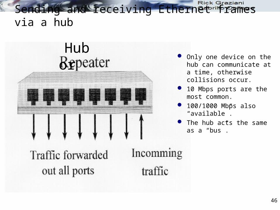
Sending and receiving Ethernet frames via a hub
Hub or Only one device on the hub
can communicate at a time, otherwise collisions occur.
10 Mbps ports are the most common.
100/1000 Mbps also “available”.
The hub acts the same as a “bus”.

47
Sending and receiving Ethernet frames via a hub
So, what does a hub do when it receives information?
A hub is nothing more than a multiport repeater.
1111 2222
3333 4444
5555
?
11113333

48
Repeaters
Signals can only travel so far through media before they weaken, and become garbled.
This weakening of signals is called attenuation. Attenuation increases when:
Media distances are lengthened Nodes are added to the media
Repeaters: take in weakened signals clean them up regenerate them send them on their way along the network

49
Repeater: Layer 1 Device
Repeaters are Layer 1 devices. They do NOT look at:
Layer 2, Data Link (MAC, Ethernet) addresses
Layer 3, IP Addresses.
Signal come in … signal go out. (after I amplify
it)

50
Hub
Hub is nothing but a multiport repeater. Hubs are Layer 1 devices. Data that comes in one port is sent out all other ports, except for the port
it came in on.

51
Hubs
Hubs allow computers and other network devices to communicate with each other, and use a star topology.
Like a repeater, a hub regenerates the signal. Hubs have the same disadvantage as a repeater, anything it
receives on one port, it FLOODS out all other ports. Wherever possible, hubs should be replace by switches. More LATER!

52
Sending and receiving Ethernet frames via a hub
The hub will flood it out all ports except for the incoming port.
Hub is a layer 1 device. A hub does NOT look at layer 2
addresses, so it is fast in transmitting data.
Disadvantage with hubs: A hub or series of hubs is a single collision domain (coming)
A collision will occur if any two or more devices transmit at the same time within the collision domain.
1111 2222
3333 4444
5555
11113333
Nope
Nope
Nope
For me!

53
Sending and receiving Ethernet frames via a hub
Another disadvantage with hubs is that is take up unnecessary bandwidth on other links.
1111 2222
3333 4444
5555
11112222
Nope
Nope
Nope
For me!
Wasted bandwidth

54
Sending and receiving Ethernet frames via a hub
What happens when two host on the same hub, or when multiple hubs are connected, transmit at the same time?
1111 2222
3333 4444
5555
?
11112222
33334444

55
Sending and receiving Ethernet frames via a hub
Collision occurs. Although, hubs have little
latency, CSMA/CD requires resending of frames and adds latency.
1111 2222
3333 4444
5555
Collision
11112222
33334444
X

56
Half-duplex (Introduction)
Hubs operate only in Half-duplex. Half-duplex means that only one end can send at a time. With half-duplex NICs, a host can only transmit or receive, not both at the
same time, or a collision will occur. When multiple devices are connected to a hub or series of hubs, only one
device can transmit. Uses CSMA/CD. If the a carrier is detected, then the NIC will not transmit. Ethernet hubs and repeaters can only operate in half-duplex mode.
Half-duplex

57
Half-Duplex mode
All of these Ethernet NICs and ports on the hubs are operating in Half-Duplex mode.
When multiple devices are connected to a hub or series of hubs, only one device can transmit.

58
Collision Domain: Shared Access
Collision domain (Wikipedia): A group of Ethernet or Fast Ethernet devices in a CSMA/CD LAN that are connected by repeaters/hubs and compete for access on the network. Only one device in the collision domain
may transmit at any one time, and the other devices in the domain listen to the network in order to avoid data collisions.
A collision domain is sometimes referred to as an Ethernet segment.
If you connect several computers to a single medium that is only connected by repeaters and hubs (Layer 1 devices), you have a shared-access situation, and you have a single collision domain.

59
Full-duplex (More in next section)
Full-duplex is allows simultaneous communication between a pair of stations or devices.
Full-duplex allows devices to send and receive at the same time. Both ends of the link must be in full-duplex mode. Most switches operate at either full-duplex but can operate in half-duplex. If a hub is connected to a switch, the switch port must be in half-duplex. The collision domain will end at the switch port.

60
Where are the collision domains?What would be the duplex settings?
hub hub hub hub hub hub
hub hub
router

61
Where are the collision domains?
hub hub hub hub hub hub
hub hub
router
Single Collision Domain

62
What would be the duplex settings?
hub hub hub hub hub hub
hub hub
router
Half-duplex
Half-duplex
hub

63
Where are the collision domains?What would be the duplex settings?
hub hub hub hub hub hub
switch switch
router

64
Where are the collision domains?What would be the duplex settings?
hub hub hub hub hub hub
switch switch
router
Collision Domains Collision Domains

65
What would be the duplex settings?
hub hub hub hub hub hub
switch switch
router
Half-duplex
Half-duplex
Full-duplex
hub

66
Where are the collision domains?What would be the duplex settings?
switch hub hub switch switch switch
switch switch
router

67
Where are the collision domains?
switch hub hub switch switch switch
switch switch
router
Collision Domains

68
What would be the duplex settings?
switch hub hub switch switch switch
switch switch
router
Full-duplex
Half-duplex
Full-duplex
switch

69
All scenarios are multiaccess networks
switch hub hub switch switch switch
switch switch
router

Chapter 9Ethernet – Part 1
CIS 82 Routing Protocols and Concepts
Rick Graziani
Cabrillo College
Last Updated: Fall 2009