Embed Size (px)
Citation preview

1
Chapter 9: A Closer Look at System Hardware 1
Chapter 9: A Closer Look at System
Hardware
CS10001 – Computer Literacy
Chapter 9: A Closer Look at System Hardware 2
Topics Discussed
Digital Data and Switches Manual Electrical
Digital Data Representation Decimal to Binary (Numbers) Characters and Symbols Other (Negative, Fractional, Hexadecimal)
CPU Digital Processing Machine Cycle In-Depth Machine Cycle Stages
Chapter 9: A Closer Look at System Hardware 3
Digital Data
Recall that bits are the alphabet of the binary language. They represent the status of “off” (0) or “on” (1).
Bits may be thought of as language devices that control the states of “off” or “on”. They are considered to be binary switches.
Chapter 9: A Closer Look at System Hardware 4
Digital Data
Electrical switches are devices inside the computer with the capability of representing the states of the binary language, 0 or 1.
So, computers are nothing more than big devices of electrical switches? How is that accomplished?

2
Chapter 9: A Closer Look at System Hardware 5
Examples of Switches
Vacuum tubes allowed or blocked the flow of electrical current in early computers (1940s). Big Bulky Unreliable Unsafe
Vacuum tube
Chapter 9: A Closer Look at System Hardware 6
Examples of Switches
Transistors incorporated silicon semiconductors to allow or block the electrical flow of digital information. Smaller Cheaper Cooler Still big Transistors
Chapter 9: A Closer Look at System Hardware 7
Examples of Switches
Integrated circuits are microprocessors, or chips, embedded with a CPU. Contains millions of transistors in a very small space (1970s). Smallest Cheapest Fastest
Integrated circuit
Chapter 9: A Closer Look at System Hardware 8
Digital Data Representation
Recall that the binary number system is the language of computers. It is used by the computer to represent all data, instructions and programs.
Because it is a “number system”, it is an organized plan for number representation.
It consists of two digits: “0” and “1”.
3
Chapter 9: A Closer Look at System Hardware 9
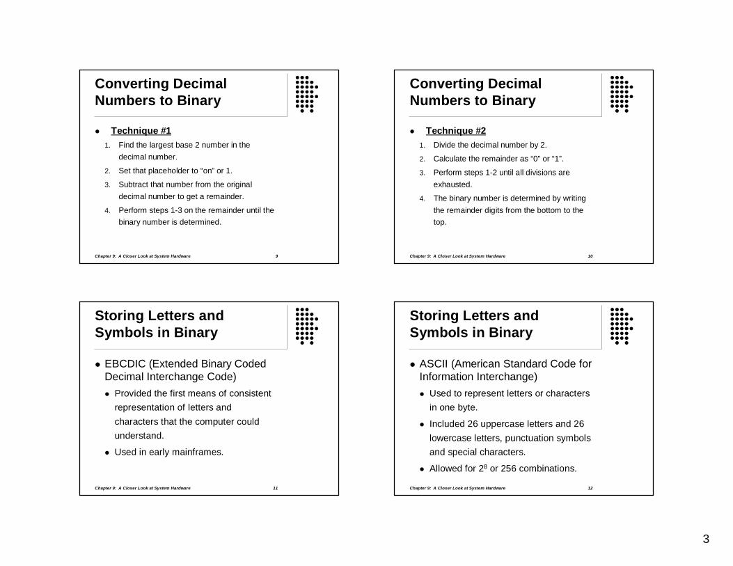
Converting Decimal Numbers to Binary
Technique #1 1. Find the largest base 2 number in the
decimal number.
2. Set that placeholder to “on” or 1.
3. Subtract that number from the original decimal number to get a remainder.
4. Perform steps 1-3 on the remainder until the binary number is determined.
Chapter 9: A Closer Look at System Hardware 10
Converting Decimal Numbers to Binary
Technique #2 1. Divide the decimal number by 2.
2. Calculate the remainder as “0” or “1”.
3. Perform steps 1-2 until all divisions are exhausted.
4. The binary number is determined by writing the remainder digits from the bottom to the top.
Chapter 9: A Closer Look at System Hardware 11
Storing Letters and Symbols in Binary
EBCDIC (Extended Binary Coded Decimal Interchange Code) Provided the first means of consistent
representation of letters and characters that the computer could understand.
Used in early mainframes.
Chapter 9: A Closer Look at System Hardware 12
Storing Letters and Symbols in Binary
ASCII (American Standard Code for Information Interchange) Used to represent letters or characters
in one byte.
Included 26 uppercase letters and 26 lowercase letters, punctuation symbols and special characters.
Allowed for 28 or 256 combinations.

4
Chapter 9: A Closer Look at System Hardware 13
Storing Letters and Symbols in Binary
Unicode Expanded ASCII and allowed a
representation of all characters and all symbols for all languages (historic and modern).
Utilized 16 bits for the representation of one byte.
Allowed for 216 or approximately 65,000 combinations.
Chapter 9: A Closer Look at System Hardware 14
Other Binary Representations
Negative numbers Uses a sign bit CPU notified by program
Fractional numbers Utilize a 32-bit system Representations standardized by IEEE
(Institute of Electrical and Electronics Engineers)
Chapter 9: A Closer Look at System Hardware 15
Other Binary Representations
Hexadecimal numbers Uses an alphabet of 16 digits, 0-9 and
A-F. Easier representations for humans
because binary strings are too long and cumbersome.
Where else was the hexadecimal number system discussed? This will likely be seen on our class project.
Chapter 9: A Closer Look at System Hardware 16
The CPU and Digital Processing
Recall that the CPU is: The “brains” of the computer. Fits on a microprocessor chip. Is located on the motherboard with
memory. Executes all the instructions (user-
defined or operating system). Is part of the computer system’s
platform.

5
Chapter 9: A Closer Look at System Hardware 17
The CPU and Digital Processing
How are CPUs different? By processing power (number of
transistors). By clock speed (its work pace). By amount of immediate access
memory (cache). By hyperthreading (processing two
separate instruction sets--one before the other finishes or both simultaneously).
Chapter 9: A Closer Look at System Hardware 18
In Depth: The CPU Machine Cycle
Recall that the machine cycle is the pace at which instructions and programs are processed by the CPU.
Measured in Hz (Hertz) and clock speed, as determined by the system clock.
It has four steps: fetch, decode, execute and store.
Chapter 9: A Closer Look at System Hardware 19
In Depth: The CPU Machine Cycle
The system clock is built into the motherboard and controls the stages of the machine cycle.
Its clock cycle beats steadily and sets the processing pace.
The clock speed is the pace at which machine cycles are occurring.
Chapter 9: A Closer Look at System Hardware 20
In Depth: The CPU Machine Cycle
The CPU’s control unit manages the switches inside the CPU so that it can remember the proper stage of the machine cycle (preprogrammed).
With each beat of the system clock, switches are set for that stage.
The work associated with that stage is performed.

6
Chapter 9: A Closer Look at System Hardware 21
In Depth: Machine Cycle Stages
Fetch Stage Gathers the necessary binary code for
the instruction or program from RAM. Moves the instruction from RAM to the
CPU registers which are special storage areas on the CPU.
The instruction remains in the registers until executed.
Chapter 9: A Closer Look at System Hardware 22
In Depth: Machine Cycle Stages
Fetch Stage – cont’d: Using cache memory Level 1 is on the CPU.
Level 2 is on the CPU but farther away.
Chapter 9: A Closer Look at System Hardware 23
In Depth: Machine Cycle Stages
Decode Stage Translates the instruction into
something the CPU understands.
Uses specific instruction sets for the translation.
Signals the registers (via the control unit) about which data to send to the ALU.
Chapter 9: A Closer Look at System Hardware 24
In Depth: Machine Cycle Stages
Execute Stage Data is sent to the ALU from the
registers, based on word size.
The ALU performs the calculations on the data. Arithmetic: Add, Subtract, Multiply, Divide
Comparison: <, >, =, not equal
Logical: AND, OR, NOT

7
Chapter 9: A Closer Look at System Hardware 25
In Depth: Machine Cycle Stages
Store Stage Result from the ALU is stored in the
registers. Register for storage is noted in the
instruction.
The cycle begins again with the next instruction to be processed.
Chapter 9: A Closer Look at System Hardware 26
Other Topics Discussed
Other RAM Dynamic RAM Static RAM
The Bus Local bus Expansion bus
Making Computers Faster Pipelining New instruction sets Multiple processing Parallel processing
Chapter 9: A Closer Look at System Hardware 27
RAM: More Temporary Storage
Recall that RAM: Is located on the motherboard in
memory modules (memory cards). Holds all the data and instructions
needed by the CPU and OS. Has an access time measured in
nanoseconds. Measured in MB or GB.
Chapter 9: A Closer Look at System Hardware 28
RAM: More Temporary Storage
DRAM (Dynamic RAM) Cheap and basic Access time = 60ns Uses transistors, capacitors and
refresh signals for individual bits.

8
Chapter 9: A Closer Look at System Hardware 29
RAM: More Temporary Storage
DRAM (Dynamic RAM) – cont’d.
Hierarchy
SDRAM (synchronous DRAM)
DDR SDRAM (double data rate SDRAM)
DDR2 SDRAM
Chapter 9: A Closer Look at System Hardware 30
RAM: More Temporary Storage
SRAM (Static RAM) Faster than DRAM
More expensive than DRAM
Uses more transistors for bits, but no capacitors or refresh rates
Commonly used for the CPU cache
Chapter 9: A Closer Look at System Hardware 31
RAM: More Temporary Storage
What else about RAM memory modules? DIMMs (dual inline memory modules) Pentium processors, 64-bit bus
SIMMs (single inline memory modules) Pre-Pentium processors, 64-bit bus was
emulated in matched 32-bit buses
Chapter 9: A Closer Look at System Hardware 32
Bus: CPU Data Highway
A bus is an electrical wire located within the system circuitry. Considered to be a data “highway”
This highway is traveled by data (bits) and links the various computer components.

9
Chapter 9: A Closer Look at System Hardware 33
Bus: CPU Data Highway
Two bus types: Local bus On the motherboard
CPU to main memory data transfer
Expansion bus From expansion cards to motherboard
Seen in video and audio
Chapter 9: A Closer Look at System Hardware 34
Bus: CPU Data Highway
Bus Speed – More Data at a Time? Bus clock speed is the data transfer
rate from one location to another (MHz).
Bus width determines the number of bits traveling at a time (wider is better).
Bus clock speed X bus width = Data transfer rate of the bus.
Chapter 9: A Closer Look at System Hardware 35
Bus: CPU Data Highway
Bus Speed – More Speed with the Data? The bus width determines the word
size to the CPU, or the number of bits manipulated at a time.
What happens if the CPU can manipulate more bits than the bus delivers?
Bus width limitations affect the CPU’s processing performance.
Chapter 9: A Closer Look at System Hardware 36
Bus: CPU Data Highway
Expansion buses ISA and EISA connected mouse,
modem, sound card. PCI direct CPU connection for
networks and sound. AGP for graphics transfer so the PCI is
not clogged.
See page 424 for architecture details.

10
Chapter 9: A Closer Look at System Hardware 37
Making Faster Computers
Advanced CPU Designs
Pipelining
New instruction sets
Multiple processing
Parallel processing
Chapter 9: A Closer Look at System Hardware 38
Making Faster Computers
Pipelining is a technique used to boost CPU performance. CPU works on more than one
instruction at a time.
More instructions processed in a clock cycle.
More efficient CPU processing.
Chapter 9: A Closer Look at System Hardware 39
Making Faster Computers
Nonpipeling vs. Pipelining
Fetch Decode Execute Store
Fetch Decode Store
Nonpipelined CPU
Fetch Decode Store
Fetch Decode Store
Fetch Decode Store
Fetch Decode Store
Instruction 1
Instruction 1
Instruction 2
Instruction 2
Instruction 3
Instruction 4
Pipelined CPU
Execute
Execute
Execute
Execute
Execute
Chapter 9: A Closer Look at System Hardware 40
Making Faster Computers
New instruction sets The basic instruction set is the
collection of commands executable by a specific CPU.
New commands to accommodate video, audio and image processing are inserted in the basic instruction set.
New instruction sets are the result.

11
Chapter 9: A Closer Look at System Hardware 41
Making Faster Computers
Multiple processing Dual-processor Two physical CPU chips installed Used on high-end servers or mainframes
Dual-core processing Uses hyperthreading Runs multiple stages of the machine cycle
simultaneously “Appears” as if two CPU chips are present
Chapter 9: A Closer Look at System Hardware 42
Making Faster Computers
Parallel processing Designed to solve one complex
problem. Large network of computers. Each computer works on part of the
problem. Tasks are completed simultaneously.