Embed Size (px)
Citation preview

Learning with PurposeSlide 1
Learning with PurposeSlide 1
Chapter 8: Magnetism &
Electromagnetism
Instructor: Jean-François MILLITHALER
http://faculty.uml.edu/JeanFrancois_Millithaler/FunElec/Spring2017
Learning with PurposeSlide 2
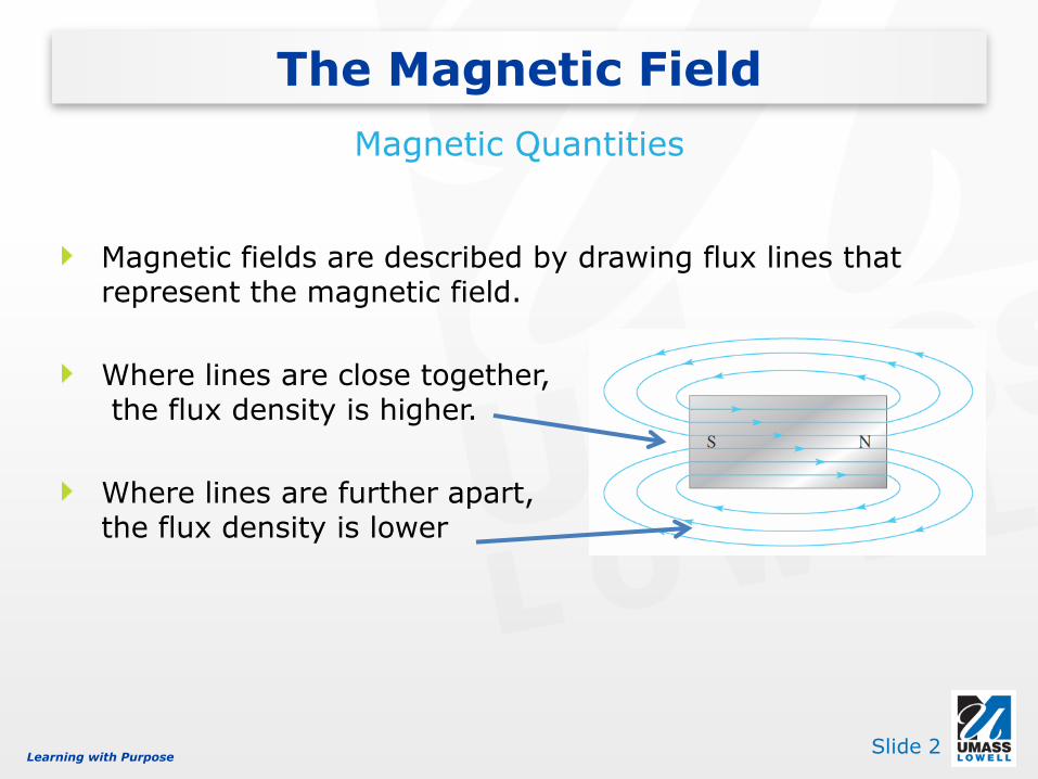
Magnetic fields are described by drawing flux lines that represent the magnetic field.
Where lines are close together,the flux density is higher.
Where lines are further apart, the flux density is lower
The Magnetic Field
Magnetic Quantities
Learning with PurposeSlide 3
The Magnetic Field
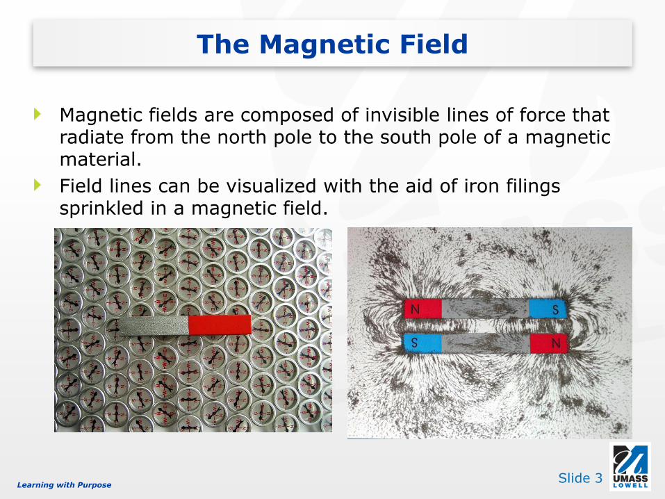
Magnetic fields are composed of invisible lines of force that radiate from the north pole to the south pole of a magnetic material.
Field lines can be visualized with the aid of iron filings sprinkled in a magnetic field.

Learning with PurposeSlide 4
Unlike poles attract
The Magnetic Field
Like poles repel

Learning with PurposeSlide 5
The magnetic field lines surrounding a magnet actually radiate in three dimensions. These magnetic field lines are always associated with moving charge.
In permanent magnets, the moving charge is due to the orbital motion of electrons.
Ferromagnetic materials have minute magnetic domains in their structure.
The Magnetic Field

Learning with PurposeSlide 6
In ferromagnetic materials such as iron, nickel, and cobalt, the magnetic domains are randomly oriented when unmagnetized. When placed in a magnetic field, the domains become aligned, thus they effectively become magnets.
The Magnetic Field
Magnetic Materials
The magnetic domains are randomly oriented in the unmagnetized material
The magnetic domains become aligned when the material is magnetized
Learning with PurposeSlide 7
Magnetic Flux
Wildhelm Eduard Weber, German physicist, 1804-1891Nikola Tesla, Croatian Engineer, 1856-1943
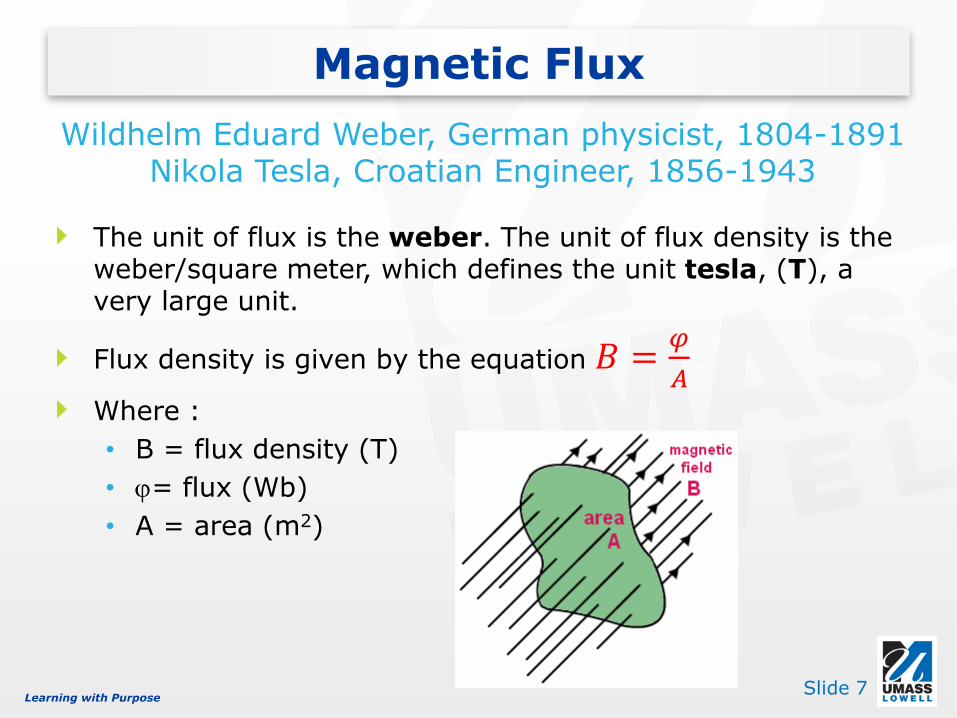
The unit of flux is the weber. The unit of flux density is the weber/square meter, which defines the unit tesla, (T), a very large unit.
Flux density is given by the equation 𝐵 =𝜑
𝐴Where :
• B = flux density (T)
• j= flux (Wb)
• A = area (m2)
Learning with PurposeSlide 8
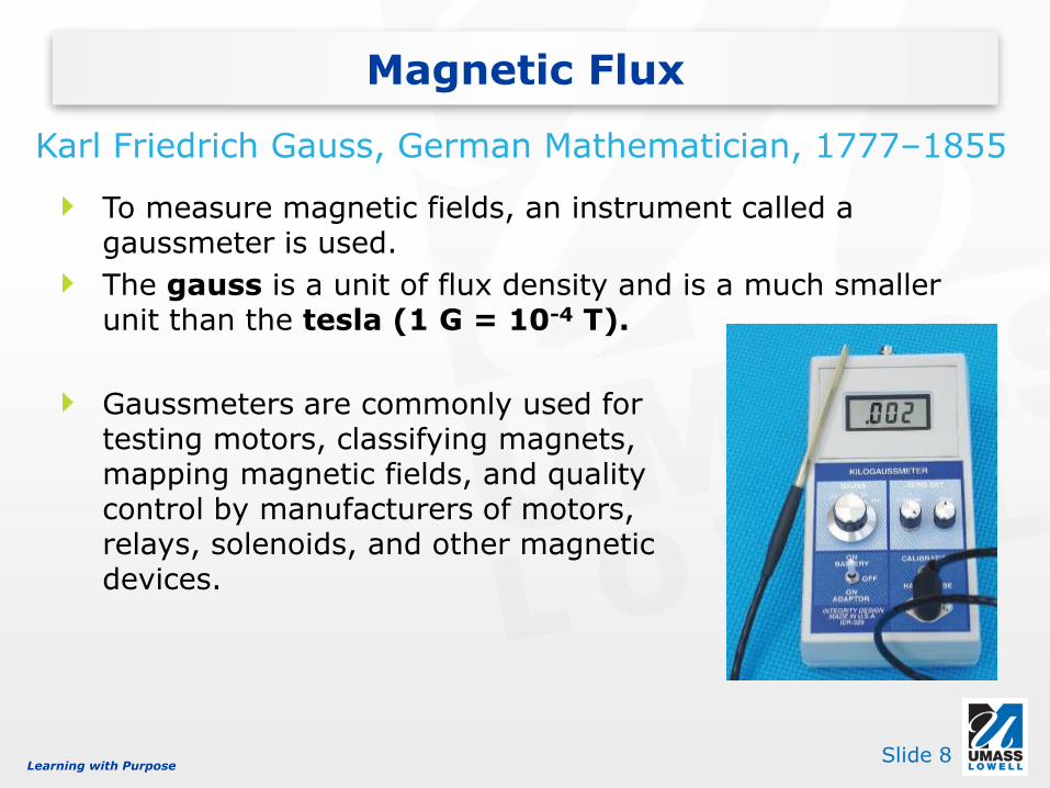
To measure magnetic fields, an instrument called a gaussmeter is used.
The gauss is a unit of flux density and is a much smaller unit than the tesla (1 G = 10-4 T).
Gaussmeters are commonly used fortesting motors, classifying magnets,mapping magnetic fields, and qualitycontrol by manufacturers of motors,relays, solenoids, and other magneticdevices.
Magnetic Flux
Karl Friedrich Gauss, German Mathematician, 1777–1855
Learning with PurposeSlide 9
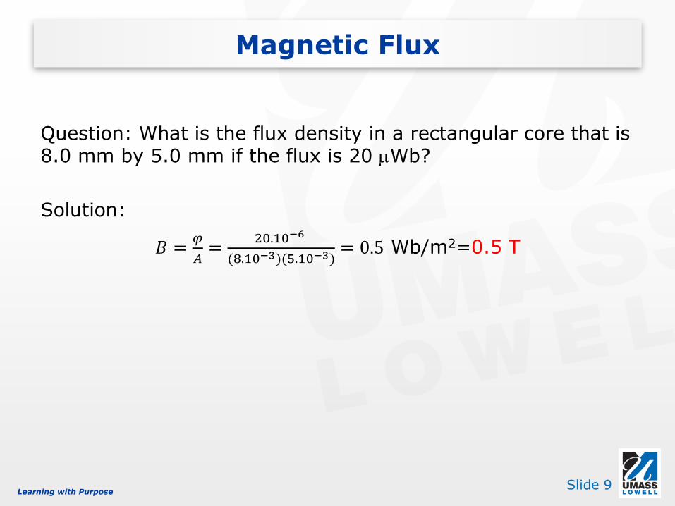
Question: What is the flux density in a rectangular core that is 8.0 mm by 5.0 mm if the flux is 20 mWb?
Solution:
𝐵 =𝜑
𝐴=
20.10−6
(8.10−3)(5.10−3)= 0.5 Wb/m2=0.5 T
Magnetic Flux

Learning with PurposeSlide 10
Electro-magnets
Magnetic Flux
Applications
Speakers
Electric motors
Learning with PurposeSlide 11
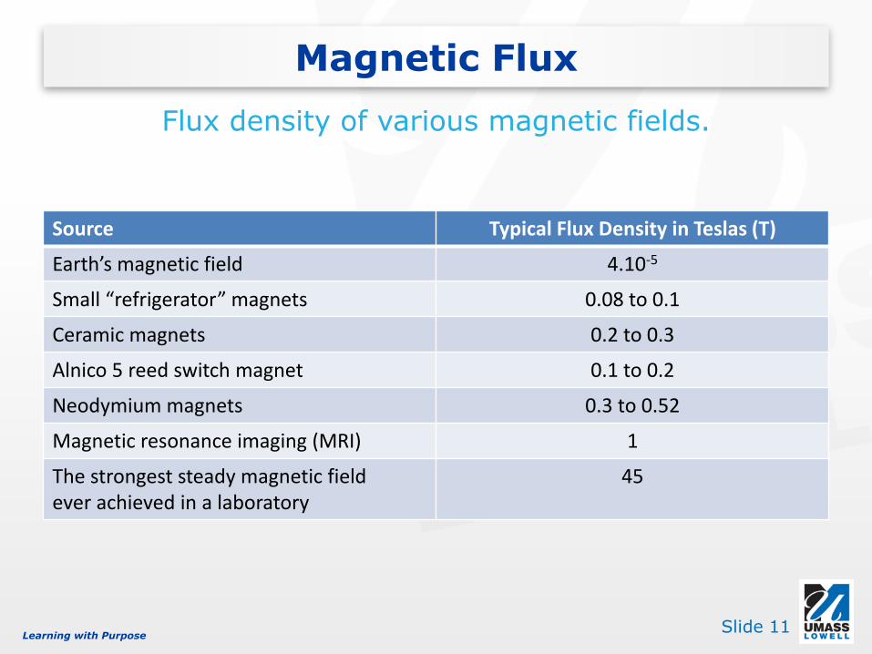
Source Typical Flux Density in Teslas (T)
Earth’s magnetic field 4.10-5
Small “refrigerator” magnets 0.08 to 0.1
Ceramic magnets 0.2 to 0.3
Alnico 5 reed switch magnet 0.1 to 0.2
Neodymium magnets 0.3 to 0.52
Magnetic resonance imaging (MRI) 1
The strongest steady magnetic fieldever achieved in a laboratory
45
Magnetic Flux
Flux density of various magnetic fields.
Learning with PurposeSlide 12
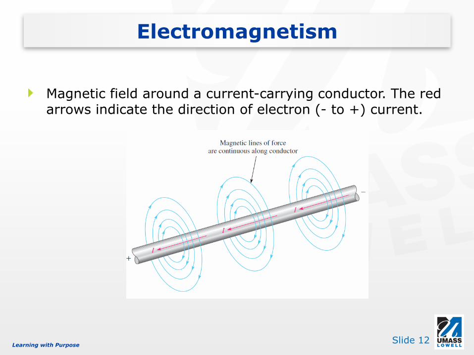
Magnetic field around a current-carrying conductor. The red arrows indicate the direction of electron (- to +) current.
Electromagnetism

Learning with PurposeSlide 13
Magnetic flux lines surround a current carrying wire.
The field lines are concentric circles.
As in the case of bar magnets, the effects of electrical current can be visualized with iron filings around the wire –the current must be large to see this effect.
Electromagnetism

Learning with PurposeSlide 14
An aid to remembering the direction of the lines of force
Thumb: pointing in the direction of current
Fingers: direction of magnetic lines of force
Left-Hand Rule

Learning with PurposeSlide 15
Permeability (m) defines the ease with which a magnetic field can be established in a given material. It is measured in units of the weber per ampere-turn meter.
The permeability of a vacuum (m 0) is 4p x 10-7 weber per ampere-turn meter, which is used as a reference.
Relative Permeability (m r) is the ratio of the absolute permeability to the permeability of a vacuum.
𝜇𝑟 =𝜇
𝜇0
Electromagnetic Properties

Learning with PurposeSlide 16
Reluctance (R) is the opposition to the establishment of a magnetic field in a material.
𝑅 =𝑙
𝜇𝐴
R = reluctance (A-t/Wb)
l = length of the path (m)
m = permeability (Wb/A-t m)
A = area in m2
Electromagnetic Properties

Learning with PurposeSlide 17
Recall that magnetic flux lines surround a current-carrying wire. A coil reinforces and intensifies these flux lines.
The cause of magnetic flux is called magnetomotive force (mmf), which is related to the current and number of turns of the coil.
𝐹𝑚 = 𝑁𝐼
Fm = magnetomotice force (A-t)
N = number of turns of wire in a coil
I = current (A)
Electromagnetic Properties

Learning with PurposeSlide 18
Ohm’s law for magnetic circuits is
𝜑 =𝐹𝑚𝑅
Flux (𝜑) is analogous to current
Magnetomotive Force (Fm) is analogous to voltage
Reluctance (R) is analogous to resistance
Problem: What flux is in a core that is wrapped with a 300 turn coil with a current of 100 mA if the reluctance of the core is 1.5 x 10⁷ A-t/Wb ?
2.0 mWb
Electromagnetic Properties

Learning with PurposeSlide 19
The magnetomotive force (mmf) is not a true force in the physics sense, but can be thought of as a cause of flux in a core or other material.
Electromagnetic Properties
Current in the coilcauses flux in theiron core
What is the mmf if a250 turn coil has 3 Aof current?
Answer: 750 A-t

Learning with PurposeSlide 20
Reversing the current in the coil causes the electromagnetic field to reverse.
Electromagnetic Properties
The Electromagnet

Learning with PurposeSlide 21
How much flux is established in the magnetic path if the reluctance of the material is 2.8*105 At/Wb?
𝜑 =𝐹𝑚𝑅=𝑁𝐼
𝑅=500 ∗ 0.3
2.8 ∗ 105= 5.36 ∗ 10−4𝑊𝑏 = 536 𝜇𝑊𝑏
Electromagnetic Properties
Learning with PurposeSlide 22
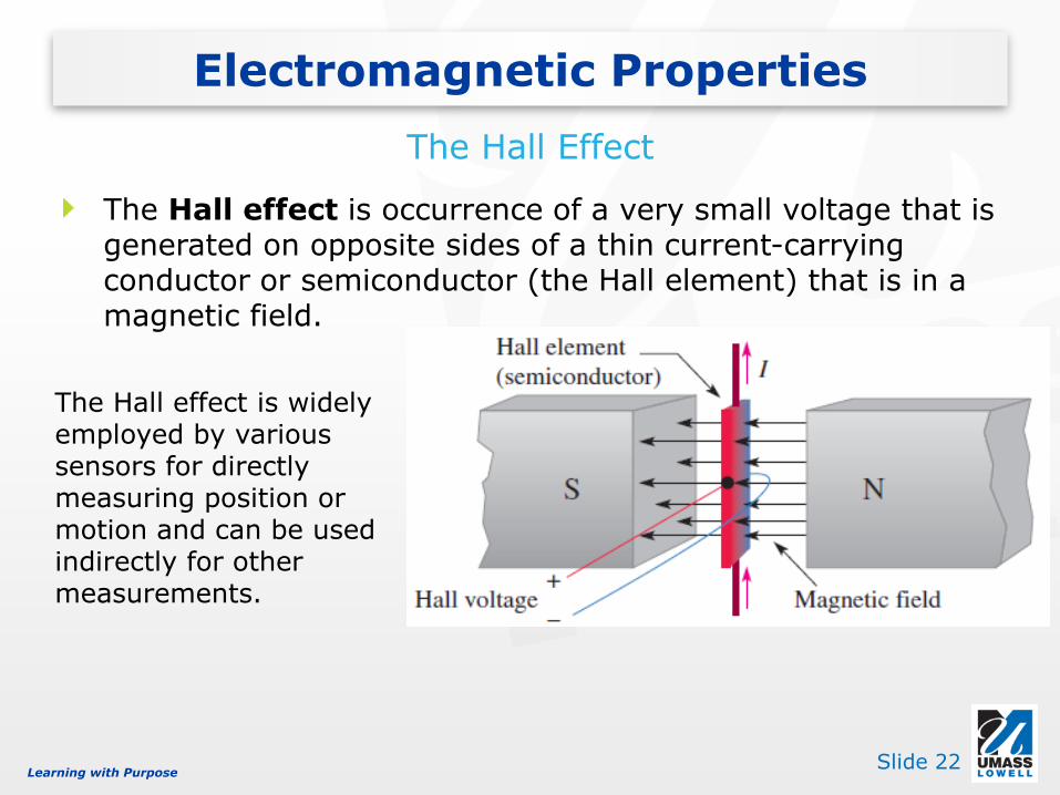
The Hall effect is occurrence of a very small voltage that is generated on opposite sides of a thin current-carrying conductor or semiconductor (the Hall element) that is in a magnetic field.
Electromagnetic Properties
The Hall Effect
The Hall effect is widely employed by various sensors for directly measuring position or motion and can be used indirectly for other measurements.

Learning with PurposeSlide 23
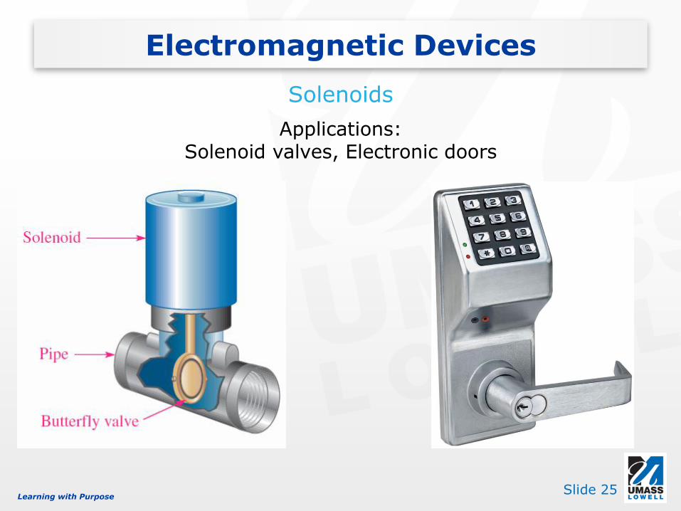
A solenoid is a magnetic device that produces mechanical motion from an electrical signal.
Electromagnetic Devices
Solenoids

Learning with PurposeSlide 24
Unenergized (no voltage or current)plunger extended
Electromagnetic Devices
Solenoids
Energizedplunger retracted
Basic solenoid operation
Learning with PurposeSlide 25
Electromagnetic Devices
Solenoids
Applications: Solenoid valves, Electronic doors

Learning with PurposeSlide 26
A relay is an electrically controlled switch; a small control voltage on the coil can control a large current through the contacts.
Electromagnetic Devices
Relays
Unenergized: continuity from terminal 1 to terminal 2
Energized: continuity from terminal 1 to terminal 3

Learning with PurposeSlide 27
Electromagnetic Devices
Reed Relays
Unenergized Energized

Learning with PurposeSlide 28
Electromagnetic Devices
Speaker
Convert electrical signal into sound
Learning with PurposeSlide 29
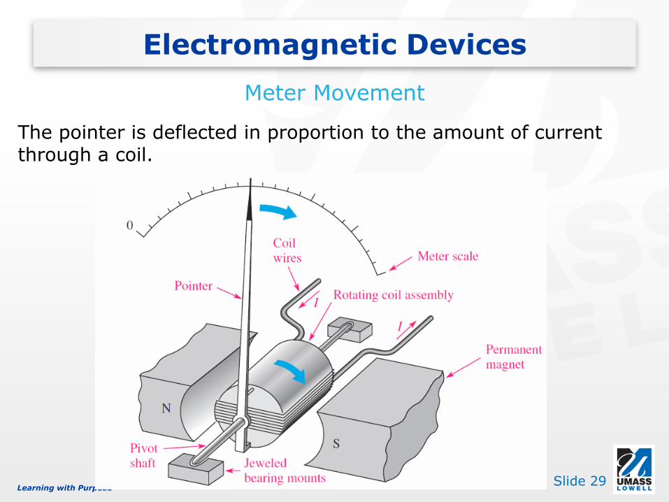
Electromagnetic Devices
Meter Movement
The pointer is deflected in proportion to the amount of current through a coil.

Learning with PurposeSlide 30
Electromagnetic Devices
Magnetic Disk and Tape Read/Write Head
The magnetic flux from the write head follows the low reluctance path through the moving magnetic surface.
When read head passes over magnetized spot, an induced voltage appears at the output.

Learning with PurposeSlide 31
When a magnetizing force is applied to a material, the magnetic flux density in the material changes in a certain way.
Magnetic Hysteresis

Learning with PurposeSlide 32
Magnetic field intensity is the magnetomotive force per unit length of a magnetic path.
H = Magnetic field intensity (Wb/A-t m)
Fm = magnetomotive force (A-t)
l = average length of the path (m)
N = number of turns
I = current (A)
Magnetic field intensity represents the effort that a given current must put into establishing a certain flux density in a material.
Magnetic Hysteresis
Magnetic Field Intensity
𝐻 =𝐹𝑚
𝑙or 𝐻 =
𝑁𝐼
𝑙

Learning with PurposeSlide 33
If a material is permeable, then a greater flux density will occur for a given magnetic field intensity. The relation between B (flux density) and H (the effort to establish the field) is
m = permeability (Wb/A-t m).
H = Magnetic field intensity (Wb/A-t m).
This relation between B and H is valid up to saturation, when further increase in H has no affect on B.
Magnetic Hysteresis
Magnetic Field Intensity
𝐵 = 𝜇𝐻
Learning with PurposeSlide 34
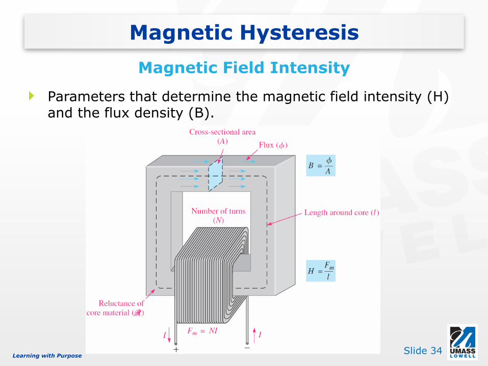
Parameters that determine the magnetic field intensity (H) and the flux density (B).
Magnetic Hysteresis
Magnetic Field Intensity

Learning with PurposeSlide 35
As H is varied, the magnetic hysteresis curve is developed.
Magnetic Hysteresis
Development of a magnetic hysteresis (B-H) curve

Learning with PurposeSlide 36
A B-H curve is referred to as a magnetization curve for the case where the material is initially unmagnetized.
The B-H curve differs for different materials; magnetic materials have in common much larger flux density for a given magnetic field intensity.
Magnetic Hysteresis
Magnetization Curve

Learning with PurposeSlide 37
When a wire is moved across a magnetic field, there is a relative motion between the wire and the magnetic field.
When a magnetic field is moved past a stationary wire, there is also relative motion.
In either case, the relative motion results in an induced voltage in the wire.
Relative motion

Learning with PurposeSlide 38
The induced voltage due to the relative motion between the conductor and the magnetic field when the motion is perpendicular to the field is dependent on three factors:
• the relative velocity (motion is perpendicular)
• the length of the conductor in the magnetic field
• the flux density
When a straight conductor moves perpendicular to a constant magnetic field, the induced voltage is given by
where is the induced voltage in volts, is the component of the magnetic flux density that is perpendicular to the moving conductor (in teslas), l is the length of the conductor that is exposed to the magnetic field, and v is the velocity of the conductor in m /s
Induced Voltage
Magnetic Field Intensity
𝑣𝑖𝑛𝑑 = 𝐵⟘𝑙𝑣

Learning with PurposeSlide 39
Faraday experimented with generating current by relative motion between a magnet and a coil of wire. The amount of voltage induced across a coil is determined by two factors:
• The rate of change of the magnetic flux with respect to the coil.
• The number of turns of wire in the coil.
Faraday’s Law
Michael Faraday, English Physicist, 1791-1867

Learning with PurposeSlide 40
The amount of induced voltage is directly proportional
to the rate of change of the magnetic field with respect to the coil
Faraday’s Law
Michael Faraday, English Physicist, 1791-1867

Learning with PurposeSlide 41
A demonstration of Faraday’s second observation: The amount of induced voltage is directly proportional to the number of turns in the coil.
Faraday’s Law
Michael Faraday, English Physicist, 1791-1867
Learning with PurposeSlide 42
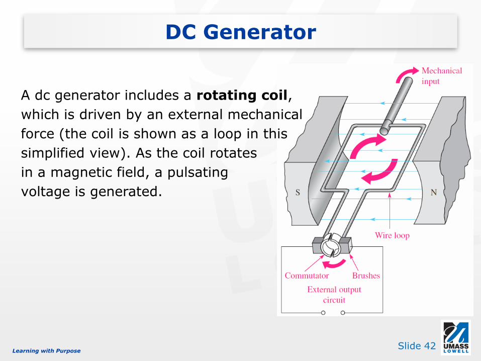
A dc generator includes a rotating coil,
which is driven by an external mechanical
force (the coil is shown as a loop in this
simplified view). As the coil rotates
in a magnetic field, a pulsating
voltage is generated.
DC Generator

Learning with PurposeSlide 43
DC Generator

Learning with PurposeSlide 44
The magnetic structure of a generator (or motor).
DC Generator

Learning with PurposeSlide 45
A dc motor converts electrical energy to mechanical motion by action of a
magnetic field set up by the rotor.
The rotor field interacts with the stator
field, producing torque, which
causes the output shaft to rotate.
DC Motor

Learning with PurposeSlide 46
SYMBOL QUANTITY SI UNIT
B Magnetic flux density Tesla (T)
f Flux Weber (Wb)
m Permeability Webers/ampere-turn meter (Wb/At m)
R Reluctance Ampere-turns/weber (At/Wb)
Fm Magnetomotive force (mmf) Ampere-turn (At)
H Magnetic field intensity Ampere-turns/meter (At/m)
F Force Newton (N)
T Torque Newton-meter (N-m)
Magnetic units