Embed Size (px)
Citation preview

Chapter 5
The Medium

2
Objectives
Explain why the two wires connecting the central exchange to a telephone are known as the local loop.
Explain why twisted-pair copper wire is used instead of fiber for the local loop.
Know the color code for wires inside a cable. Understand the principles behind the design
of the local loop.

3
Objectives (continued)
Explain revised resistance design. Explain modified long route design. Explain when to use revised resistance
design or modified long route design principles in designing a local loop.
Explain what a load coil is and why we use them.

4
Objectives (continued)
Explain why loops longer than 18,000 feet need to be loaded.
Explain what a jumper wire is and what it is used for.
Explain why the serving area for a central exchange located in the city is kept under 3 miles.
Explain what a carrier serving area (CSA) is.

5
Objectives (continued)
Explain why higher-frequency signals are attenuated more than low-frequency signals when they are transmitted over a nonloaded pair.
Explain the differences between feeder, distribution, and drop cables.
Explain what a SLC-96 TDM system is.

6
Objectives (continued)
Explain why we might use SLC-96 instead of twisted-pair copper wire to serve as the medium to connect telephones to the central exchange.
Explain when we would use a loop extender and/or a voice frequency repeater (VFR).
Explain why the medium for SONET must be fiber optic cable.

7
The Medium
Every communication system requires a medium connecting the transmitter to the receiver.
Wire is an excellent conductor of electrical energy, which is why it is used to connect telephones to the central exchange.
The wiring used to connect telephones to the central exchange is called the local loop.

8
Analog Phone Line Connected to a Digital Central Exchange

9
5.1 Local Loop
The twisted-pair local loop is the weakest link of the telecommunications network. It limits our communication to low-frequency audio
signals. It is the most costly portion.
Originally both the local loop and toll loop wire constructed using wire as a facility.
In the telephone industry, the engineering and construction of these facilities are the responsibility of outside plant engineers.

10
New York City 1890 – Open Wire Used for Outside Plant

11
5.2 Introduction of Plastic Insulated Cable
The use of insulated wires makes it possible to put many wires in one cable.
They will be electrically isolated from each other by the insulation surrounding each wire.
Copper conducts electricity better than iron, and the choice of copper allows the use of smaller diameter wire.
While shellac and lead were originally used, each wire is now covered with plastic.

12
Plastic Insulated Cable

13
Plastic Insulated Cable

14
5.3 Plastic Insulated Cable (PIC) Color Code
Colors used in PICs Mate (primary) colors: white, red, black, yellow, and violet Secondary colors: blue, orange, green, brown, and slate
Color of plastic around each wire composed of two colors Tip wire: wide band of mate, narrow band of secondary Ring wire: wide band or secondary, narrow band of mate

15
Plastic Insulated Cable Groups
Groups of 25 pairs are tied together with colored plastic strings called binders.
Larger cables are constructed by wrapping from 100 to 625 pairs in binders.

16
Table 5-1 Plastic Insulated Cable (PIC) Color Code

17
5.4 Outside Plant Resistance Design
Older telephone transmitters needed 23 milliamps of current to work properly, with a central office supply of 48 V.
Need to choose wire thickness to ensure the longest loop did not exceed 1000/1200 Ω.
Designing a loop to not exceed a stated resistance is called resistance design 26- and 24-gauge wire is used for most loops 19- and 22-gauge wire may be used for longer (7
to 20 miles) loops

18
5.5 SXS Design Criteria: 27 Milliamps of Loop Current
In the Strowger automatic step-by-step switching system, the Ring trip relay required 27 mA to operate.
Each telephone had about 400 Ω of resistance.
The Ring trip relay had 350 Ω of resistance. This would allow for the Tip lead and the
Ring lead to each have 500 Ω of resistance.

19
5.6 Transmitter Design Criteria: 23 mA and 20 mA of Loop Current
Ring trip relay design improved: Works with only 20 mA of current Has resistance of 400 Ω
Telephone improved: Works with only 20 mA of current Has resistance of 400 Ω.
SPC switching system supply increased to 52 V.
Today’s resistance design allows for a local loop of 1800 Ω.

20
5.7 Revised Resistance Design
Any loop up to 18,000 feet is engineered with nonloaded cable for a maximum resistance of 1300 Ω.
Loops between 18,000 and 24,000 feet are engineered with loaded cable for a maximum resistance of 1500 Ω.
Loaded cable has additional inductance to improve ability to handle voice over long loops.

21
5.8 Modified Long Route Design
Used for loops between 18,000 and 24,000 feet
Loop Treatment Range Extenders (loop extenders)
Boosts voltage from 52 V to 78 or 104 V Voice Frequency Repeaters (VFRs)
Sets gain so overall power loss of circuit is 4 to 8 dB
Can use 24- or 26-gauge wire Instead of 19- or 22- with RRD

22
MLRD Loop Treatment

23
5.9 Serving Area of a Central Office
The serving area of a central office depends on the geographic area it is situated in. All cable pairs terminate on the main distributing
frame (MDF). When an MDF serves more than 20,000 lines,
jumpers become too long. Serving area depends on population density. It is cheaper to use more exchanges and
smaller wire in the loop.

24
Typical Exchange Boundaries in a City

25
Exchange Boundaries in a Rural Area

26
5.10 Resistance Design: Wire Gauge Selection
Determine maximum resistance: Revised Resistance Design: 1500 to 2400 Ω Modified Long Route Design: 2400 to 2800 Ω
Choose wire gauge 26-gauge: 42 Ω per 1,000 feet 24-gauge: 26 Ω per 1,000 feet 22-gauge: 16 Ω per 1,000 feet 19-gauge: 8 Ω per 1,000 feet

27
5.11 Carrier Serving Area
The outermost customer establishes the exchange boundary for a central office.
The Carrier Serving Area (CSA) is a distant area of the exchange that can support access to DS0 digital service and ISDN without special loop treatment. 12,000 feet for 24-gauge wire 9,000 feet for 26-gauge wire

28
Carrier Serving Area

29
5.12 Voice Signals (AC) in the Local Loop
Resistance design of the outside plant ensures that the dc power loss over the local loop is within limits.
Voice signals are converted by the transmitter of the phone into variances in electric current. These variances look like ac signals. The signal varies between 27 and 33 mA about a
center point of about 30 mA.

30
5.13 Capacitive Reactance Considerations
A wire pair acts as a capacitor. The wires of the local loop have a capacitance of
about 0.83 μF per mile. The capacitance allows some voice signal to leak
from one wire to another. Capacitive reactance varies inversely with
frequency. On loops longer than 3 miles, capacitive
reactance causes significant power loss to signals above 1000 Hz.

31
5.14 Loading Cable Pairs to Improve Voice Transmission
Cable pairs shorter than 3 miles do not require loading.
Most loaded local loops will use 22- and 19-gauge wire. The cutoff frequency of the local loop can be
raised to 3800 Hz by using 88 mH coils and placing them at 6,000 ft intervals.
The cutoff frequency of the local loop can be raised to 7400 Hz by using 44 mH coils and placing them at 3,000 ft intervals.

32
Load Coils
Spacing coils 3000 ft apart is called B Spacing, spacing 4500 ft apart is D Spacing, and 6000 ft spacing is H Spacing.
Load coils are enclosed in one case and connected to two-cable stubs that will protrude outside the case.

33
Load Coil Spacing

34
Loading Cable
Loading a cable flattens out the power loss for all signals below 3,000 Hz.
The single biggest advantage of using wire as a medium is the narrow bandwidth of wire due to mutual capacitance and loading.
Load coils improve the low-frequency response of a cable, but add more loss to high-frequency signals.

35
Signal Loss Comparison: Loaded versus Unloaded Cable

36
5.15 Data on the Local Loop
The local telecommunications network was designed to handle voice frequencies. Data can be sent over specially designed local
loops and central office equipment. When modems are used, they must be used
in pairs. One modem at the transmitting end. One modem at the receiving end.

37
Digital Data Signals
Digital data signals can use wire for transmission, but only for a short distance.
Signals must be regenerated every 1 to 3 miles depending on the speed of the data transmitted.
ISDN lines use digital subscriber line circuits, which will work up to 3 miles.

38
Modems Allow the Connection of a Data Circuit to the PSTN

39
5.16 Power-Loss Design
The amount of power loss that any signal has over a medium is measured in decibels (dB). dB = 10 log P2 / P1
dBm = 10 log P2 / 1 mW
For the local loop, this power loss over the wire between the central exchange and the telephone should not exceed: 8.5 dB with a signal that is 1000 Hz. The loss between 500 and 2700 Hz should be within
2.5 dB of the loss measured at 1000 Hz.

40
Twisted-Wire Pair

41
5.15 Feeder Cables, Distribution Cables, and Drop Wires
Feeder Cable provides a direct route to the area of an exchange it will serve
Main Feeder Cable Cables that leave a central exchange Contain 1800 to 3600 pairs of wires
Branch Feeder Smaller cables that main feeders are spliced out into 900 to 1800 pairs of wires
Distribution Cable 25 to 400 pairs of wires
Drop Wire (Drop Cable) connects home to a ready access terminal or a pedestal

42
Feeder and Distribution Cables

43
Pedestal

44
5.18 Subscriber Carrier
Used in outside plant as a pair-gain device. Electronic device acting as a multiplexed carrier Amplitude modulation and frequency division
multiplexing AML-1 used to add one additional customer AML-8 can add eight customers
Subscriber line carrier (or subscriber loop carrier) Uses TDM technology Can handle as many as 96 telephones SLC-96

45
Single-Channel Subscriber Carrier

46
Eight-Channel Subscriber Carrier
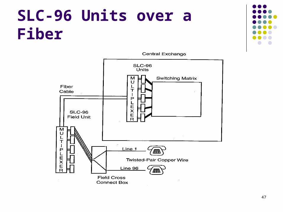
47
SLC-96 Units over a Fiber

48
5.19 Medium for Long Distance Networks
When long distance networks were first established, the only medium available was wire: 12 to 24 channels using VFRs
Later, AT&T developed a frequency division multiplexing (FDM) carrier system 600 channels on coaxial cable L5E system (1978): 13,200 channels Coaxial cable with 20 pairs, 2 spares, and
repeaters every mile: 10 L5Es

49
Long Distance Network Media
AT&T also developed carrier systems that used time division multiplexing (TDM) technology. Twisted-pair copper wire: T1 (24 channel), T1-C (48
channel), T-2 (96 channel) Coaxial cable: T3 (672 channel)
Microwave radio systems were also developed by AT&T. These systems could multiplex up to 28,244 circuits. Referred to as line-of-sight transmission

50
5.20 Fiber Optic Cable
A fiber optic strand is made by surrounding a thin fiber of glass with another layer of glass called cladding.
Fiber optic systems are noise free. AT&T introduced fiber optic technology in
1979 using graded-index fiber. A fiber optic strand carries signals in one
direction only.

51
Dense Wave Division Multiplexing
Sprint and AT&T have upgraded their fiber routes to handle as many as 516,096 channels using Dense Wave Division Multiplexing (DWDM).
At present, DWDM uses 16 or 32 different frequencies.
It is estimated that a single-mode fiber can handle 3 million channels with devices operating at 250 Gbps.

52
Dense Wave Division Multiplexing (courtesy of Sprint)

53
5.21 Fiber Technology
Light waves travel at the speed of light, but this speed will vary depending on the medium.
The refractive index, n, is given by the ratio of the speed of light in a vaccuum, c, to the speed of light in the medium, v. Air: 1.003, Water: 1.33, Glass: 1.4 – 1.9
Snell’s Law n1 sin θ1 = n2 sin θ2

54
Angles of Incidence, Reflection, and Refraction

55
Angles at the Critical Angle
56
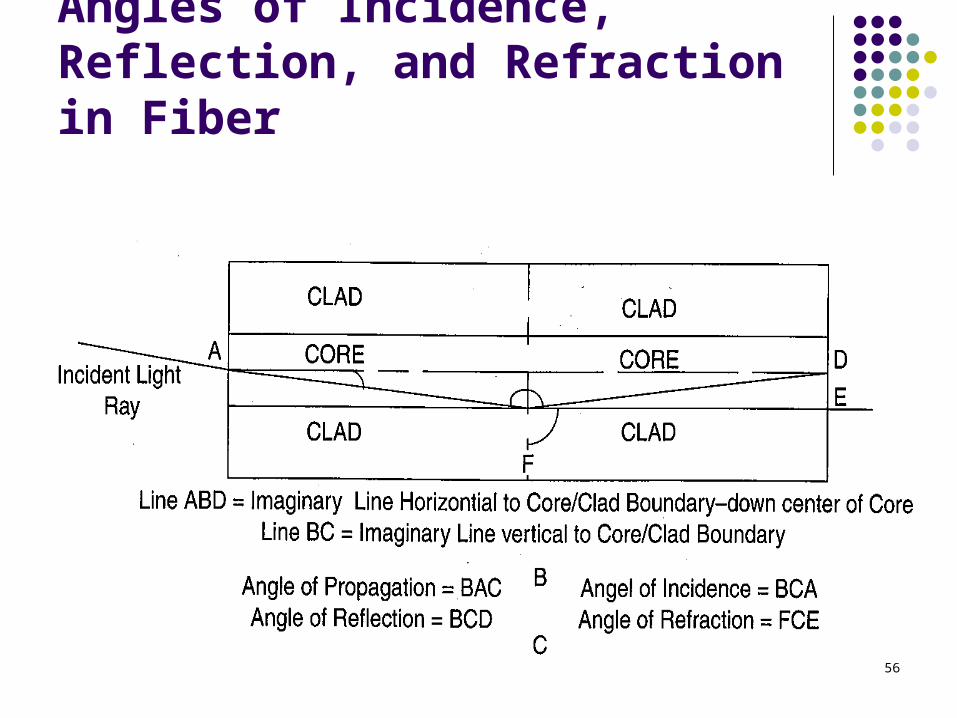
Angles of Incidence, Reflection, and Refraction in Fiber