Embed Size (px)
Citation preview

CHAPTER
3Novel twisted and coiledpolymer artificial musclesfor biomedical and roboticsapplications
Lokesh Saharan and Yonas TadesseHumanoid, Biorobotics and Smart Systems (HBS) Laboratory, Department of Mechanical
Engineering, The University of Texas at Dallas, Richardson, TX, United States
3.1 INTRODUCTION
3.1.1 DESCRIPTION
Artificial muscle is the name given to those materials that contract and relax like
the skeletal muscle upon the application of external stimuli. The stimuli could be
a chemical or physical stimulus (Tondu, 2015). There have been several methods
of creating artificial muscles based on different working mechanisms. Some of
the most common ones are electrochemical actuation, electrostatic actuators,
piezoelectric, carbon nanotube (CNT), shape memory alloys (SMAs), pneumatic
muscles (PMs), and composites. Artificial muscle has attracted the attention of
many researchers, after the long usage of engines and motors for powering
mechanical systems. Artificial muscles have been used for the design and
development of biomedical devices and biomimetic robots. However, the ideal
biomimetic robots require specially designed actuators that can replicate the
behavior of natural muscle. Natural muscles are impeccably capable of sensing,
acting, and calculating. Such replica of an artificial muscle is required for
biomedical and robotic applications that have advanced and higher performance.
In this development, most of the artificial muscles faced a limitation on one or
another front and hence mainly failed to compete with mammalian muscles. This
has led to further curiosity and recently accelerated research in the field of artifi-
cial muscles. Recently, Haines et al. introduced a better alternative to expensive
existing artificial muscles with better performances. The muscles are made by
twisting and coiling and some heat treatment, so we call them twisted and coiled
polymer (TCP) muscles (Haines et al., 2014a). These muscles have a large strain
(B50%), high power to weight ratio comparable to that of a jet engine
(5.26 kW), and can lift 100 times greater load than human muscle. We will
explain the fabrication process of these novel muscles in a later section. The
Materials for Biomedical Engineering: Nanobiomaterials in Tissue Engineering.
DOI: https://doi.org/10.1016/B978-0-12-816909-4.00003-8
© 2019 Elsevier Inc. All rights reserved.
45
muscles can be made using commercially available materials used for sewing
thread or fishing lines such as nylon 6, nylon 6,6, or polyethylene precursor
fibers.
3.1.2 FABRICATION OF BASIC TWISTED AND COILED POLYMERMUSCLES
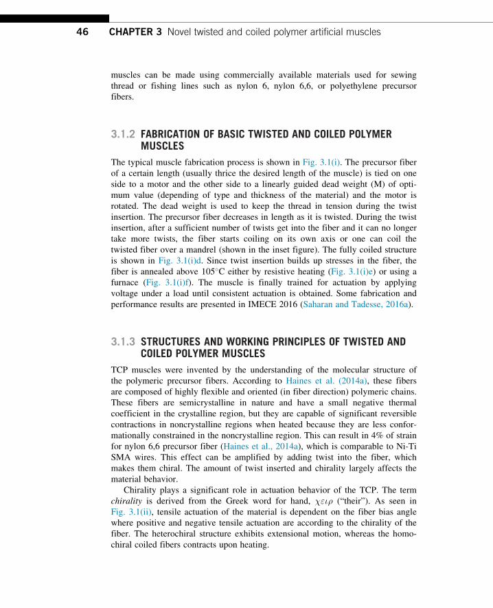
The typical muscle fabrication process is shown in Fig. 3.1(i). The precursor fiber
of a certain length (usually thrice the desired length of the muscle) is tied on one
side to a motor and the other side to a linearly guided dead weight (M) of opti-
mum value (depending of type and thickness of the material) and the motor is
rotated. The dead weight is used to keep the thread in tension during the twist
insertion. The precursor fiber decreases in length as it is twisted. During the twist
insertion, after a sufficient number of twists get into the fiber and it can no longer
take more twists, the fiber starts coiling on its own axis or one can coil the
twisted fiber over a mandrel (shown in the inset figure). The fully coiled structure
is shown in Fig. 3.1(i)d. Since twist insertion builds up stresses in the fiber, the
fiber is annealed above 105�C either by resistive heating (Fig. 3.1(i)e) or using a
furnace (Fig. 3.1(i)f). The muscle is finally trained for actuation by applying
voltage under a load until consistent actuation is obtained. Some fabrication and
performance results are presented in IMECE 2016 (Saharan and Tadesse, 2016a).
3.1.3 STRUCTURES AND WORKING PRINCIPLES OF TWISTED ANDCOILED POLYMER MUSCLES
TCP muscles were invented by the understanding of the molecular structure of
the polymeric precursor fibers. According to Haines et al. (2014a), these fibers
are composed of highly flexible and oriented (in fiber direction) polymeric chains.
These fibers are semicrystalline in nature and have a small negative thermal
coefficient in the crystalline region, but they are capable of significant reversible
contractions in noncrystalline regions when heated because they are less confor-
mationally constrained in the noncrystalline region. This can result in 4% of strain
for nylon 6,6 precursor fiber (Haines et al., 2014a), which is comparable to Ni-Ti
SMA wires. This effect can be amplified by adding twist into the fiber, which
makes them chiral. The amount of twist inserted and chirality largely affects the
material behavior.
Chirality plays a significant role in actuation behavior of the TCP. The term
chirality is derived from the Greek word for hand, χειρ (“their”). As seen in
Fig. 3.1(ii), tensile actuation of the material is dependent on the fiber bias angle
where positive and negative tensile actuation are according to the chirality of the
fiber. The heterochiral structure exhibits extensional motion, whereas the homo-
chiral coiled fibers contracts upon heating.
46 CHAPTER 3 Novel twisted and coiled polymer artificial muscles
FIGURE 3.1
(i) Fabrication process of TCP and actuation of TCP muscles: (a,b) twisting, (c,d) self-coiling, (e,f) training, and (g) twisting and coiling on mandrel. (ii)
Chirality and actuation mechanism: (a) comparison of the heterochiral and homochiral tensile and compressive actuation, (b) heterochiral coiling and
actuation mechanism, and (c) homochiral coiling and actuation mechanism. (iii) Mechanism of actuation of the TCP muscles using (a) electrothermally and
(b) hot and cold fluid. (iv) Comparison of TCP actuators with other actuator technologies, blocking stress�strain and energy density (Haines et al., 2014a;
Tadesse, 2013). CP, Conducting polymer; SMA, shape memory alloy; DE, dielectric elastomer; PM, pneumatic muscle; BISMC, bioinspired composite; BMF,
biometal fiber SMA; IPMC, ionic metal composite; Servo, small RC servo HS81; Natural, skeletal muscles; TCP, twisted and coiled polymer muscle.
Figure adapted from (ii) Haines, C.S., Lima, M.D., Li, N., Spinks, G.M., Foroughi, J., Madden, J.D., et al., 2014a. Artificial muscles from fishing line and sewing thread. Science 343,
868�872. (iv) Tadesse, Y., Wu, L., Saharan, L.K., 2016. Musculoskeletal system of bio-inspired robotic systems. Mech. Eng. 138.
When the chirality of the precursor fiber and coils matches (which is called
homochirality), then the actuator will contract whereas opposite chirality (hetero-
chirality) leads to expansion of the muscle. Fig. 3.1(ii) shows the homochiral and
heterochiral muscles and their behavior. The muscle can be fabricated with
desired chirality as per requirement. The actuation is a reversible contraction and
it depends on the material’s physical properties, for example, nylon 6,6 has a
large thermal contraction (4%�34%) between 20�C and 240�C due to its high
melting point when compared with polyethylene having a temperature range of
20�C�130�C providing smaller contractions (0.3%�16%) (Haines et al., 2014a).
Human muscle has a contraction of 20%, which is less than 34% provided by
nylon 6,6 based TCP muscle. These capabilities make these muscles a distinct
candidate for application in orthosis, prosthetics, robotics, and many other bio-
medical applications.
Fig. 3.1(iii) shows the different mechanisms of actuating the TCP muscles,
which can be either hot air blown to the surface of the structure, or hot and cold
fluid supplied in a confined space to transfer heat to the polymer structure or by
applying voltage across the polymer composite. For the electrical actuation, a
conductor or metal coating of the polymer is a necessary condition.
3.1.4 COMPARISON WITH OTHER SOFT ACTUATORS
TCP muscle is a great alternative to conventional actuators such as DC motors,
pneumatic, and hydraulic muscles including the SMA. TCP muscle has a tremen-
dous power to weight ratio. It has impeccable qualities when comparing them on
various parameters such as cost, availability, working principle, and application.
This muscle requires polymeric fibers such as nylon 6, nylon 6,6, and polyethyl-
ene as precursor material, which are readily available in many places at very low
cost. The muscle requires heat as an input, which can be provided using some
fluid like water, or it can be actuated electrothermally, which makes its applica-
tion versatile from the actuator, a sensor to energy harvester. Along with the
qualities above, this material can be easily manufactured anywhere with easily
available tools by following the standard procedure. The fabrication process will
be explained in later sections along with performance characteristics.
The important performance parameters for comparison of the muscle are the
stress and strain (Smith et al., 2011; Tadesse, 2013). Stress produced implies the
amount of force per unit area (σ5F/A) of the actuator. Strain (E5Δl/l) is
defined as the amount of the displacement produced by the actuators per unit of
its length. Strain enables us to find the suitable actuator for a given application.
The comparative chart for the actuators performance [Fig.3.1(iv) (Tadesse et al.,
2016)] in terms of stress�strain and energy per unit volume for actuators
suitable for soft robotics, humanoids, and prosthetics is of utmost important. The
chart shows the SMA being the highest in energy density 105�107 J/m3 (diagonal
lines) and stresses of greater than 100 MPa. SMA was considered to be the best
option for low-frequency applications until it was challenged by recently invented
48 CHAPTER 3 Novel twisted and coiled polymer artificial muscles
coiled and twisted polymeric muscles. SMA is expensive, difficult to fabricate,
and it has limitations such as high hysteresis (Haines et al., 2014a,b; Wu et al.,
2015b; Madden et al., 2004; Tadesse, 2013), which can be replaced by TCP
muscles.
The only limitation of TCP muscles is efficiency when compared with the DC
motors. The efficiency of the muscle is slightly above 1%. Lower efficiency can
make actuators power hungry, which can lead to the demand for large battery
packs. Efficiency issue can be easily dealt with by using a locking mechanism.
Locking mechanisms are the devices that help robotic manipulators, prosthetic
hands or orthotic devices to hold a certain position by mechanically locking the
position. These devices are helpful in robotic, prosthetic (Saharan and Tadesse,
2016c), and orthotic applications.
3.2 DETAILED FABRICATION OF THE TWISTED AND COILEDPOLYMERIC MUSCLES
TCP muscle can be fabricated by following the right procedure on the precursor
fiber. Single twisted and coiled muscle is called 1-ply muscle. Multiple 1-ply
muscle can be plied together to create 2-ply, 3-ply, or more plied muscles.
Typically, 1-ply, 2-ply, and 3-ply muscles have been reported and studied widely
in the literature. Mainly two types of precursor fibers have been described in the
literature. Silver-coated precursor fibers (Haines et al., 2014a; Saharan and
Tadesse, 2016a; Wu et al., 2016a; Cho et al., 2016) (such as mono or multifila-
ment nylon 6,6) are used to fabricate the muscles, which can be driven electro-
thermally. Silver-coated fibers have a thin coating of the silver on the precursor
fiber, which helps to generate heat in the muscle by application of electrical
potential (Joules effect). Such muscles can be used along with batteries on mobile
devices. Silver coating or painting can also be applied to the muscle during twist
insertion for the precursor fibers with no silver coating on them (Mirvakili et al.,
2014). Another type of muscles can be precursor fibers without silver coating on
them (Haines et al., 2014a; Wu et al., 2015a; Saharan and Tadesse, 2016b).
Without the silver coating, the muscle is actuated by alternating flow of hot and
cold fluid such as water. Also, recently, Semochkin (2016) has presented a device
to manufacture the TCP muscle with a heater wire in an automated manner. Both
types of the muscles have similar type of the procedure for fabrication. The pro-
cedure involves twist insertion under a certain load followed by coiling.
3.2.1 TWISTING
Twist insertion is a process in which a load of optimum values is tied to the
precursor fiber on one end and the other end is tied to a motor that rotates at a
certain speed. As described above, twist insertion will bring chirality to the
493.2 Detailed Fabrication of the Twisted and Coiled Polymeric Muscles
muscle, which amplifies the linear stroke. Typically three times the length of pre-
cursor fiber is desired of the intended muscle length. The amount of weight used
as a preload or stress (Haines et al., 2014a) and twist insertion speed (Saharan
and Tadesse, 2016a) will affect the properties of the fiber. For example, 10, 16,
and 35 MPa stresses during the coiling can give different spring indices of the
muscle of 1.7, 1.4, and 1.1, respectively, for a 127 μm, nylon 6,6 monofilament
precursor fibers, according to Haines et al. For a silver-coated multifilament nylon
6,6 of 200 μm diameter, twist insertion (Wu et al., 2016a; Tadesse et al., 2016;
Saharan and Tadesse, 2016a) was reported at 9.9 MPa. Load or weight on the
muscle during twist insertion plays an important role since too much weight can
break the fiber during twist insertion whereas less weight can cause snarling in
the fibers. Different combination of weight and speed would give a different
properties (Saharan and Tadesse, 2016a). Fig. 3.2(i) shows a typical TCP muscle
fabrication process of 1-ply muscle and plying together 1-ply muscles for making
2-ply muscles. The process (a) to (b) in the figure is the twisting process using an
electric motor at the top and a dead weight at the bottom. The weight is
constrained to translate only. The weight is not simply hung; it is supported by a
guide for the linear displacement at the fiber is twisted. These properties can be
managed for various applications by varying fabrication process. The total amount
of twist inserted in the precursor fiber affects the performance of the muscle. A
large number of twists will create high-performance muscle. The twisting will
lead to self-coiling.
3.2.2 COILING
Once the fiber is twisted extremely, it will start coiling on its own. The coil
could start from the top or the bottom along the axis. The process from (b) to
(c) in Fig. 3.2(i) is the coiling process, where an increased diameter is seen for
the coiled structure. Twist insertion will make the precursor fiber stiffer where
more twist will cause coiling of the muscle about the axis of rotation. This
coiling is a result of extreme twist insertion. The packing density of the coil
will be determined by the amount of stress during the coiling. Another type of
coiling is mandrel coiling (Wu et al., 2015c; Haines et al., 2014a). After twist
insertion, a mandrel can be used to wrap the twisted muscle around it. Various
shapes for mandrel coiling can be used to create spring structures of varying shapes
and sizes. A cylindrical muscle can be obtained by wrapping the muscle around a
cylindrical rod (Haines et al., 2014a) whereas a cone can create a conical shaped
muscle (Haines et al., 2016) and mandrel coiling will facilitate a large stroke at the
cost of the stresses produced by the muscle. Coiled muscle will try to unwind due
to internal stresses.
Muscle is largely driven by the torsion of twisting and untwisting of the fiber
under the influence of the temperature; the same amount of twist inserted in two
different fibers would cause the same amount of tensile untwist. According to the
50 CHAPTER 3 Novel twisted and coiled polymer artificial muscles
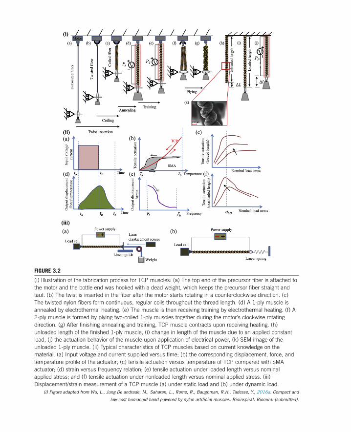
FIGURE 3.2
(i) Illustration of the fabrication process for TCP muscles: (a) The top end of the precursor fiber is attached to
the motor and the bottle end was hooked with a dead weight, which keeps the precursor fiber straight and
taut. (b) The twist is inserted in the fiber after the motor starts rotating in a counterclockwise direction. (c)
The twisted nylon fibers form continuous, regular coils throughout the thread length. (d) A 1-ply muscle is
annealed by electrothermal heating. (e) The muscle is then receiving training by electrothermal heating. (f) A
2-ply muscle is formed by plying two-coiled 1-ply muscles together during the motor’s clockwise rotating
direction. (g) After finishing annealing and training, TCP muscle contracts upon receiving heating. (h)
unloaded length of the finished 1-ply muscle, (i) change in length of the muscle due to an applied constant
load, (j) the actuation behavior of the muscle upon application of electrical power, (k) SEM image of the
unloaded 1-ply muscle. (ii) Typical characteristics of TCP muscles based on current knowledge on the
material. (a) Input voltage and current supplied versus time; (b) the corresponding displacement, force, and
temperature profile of the actuator; (c) tensile actuation versus temperature of TCP compared with SMA
actuator; (d) strain versus frequency relation; (e) tensile actuation under loaded length versus nominal
applied stress; and (f) tensile actuation under nonloaded length versus nominal applied stress. (iii)
Displacement/strain measurement of a TCP muscle (a) under static load and (b) under dynamic load.
(i) Figure adapted from Wu, L., Jung De andrade, M., Saharan, L., Rome, R., Baughman, R.H., Tadesse, Y., 2016a. Compact and
low-cost humanoid hand powered by nylon artificial muscles. Bioinspirat. Biomim. (submitted).
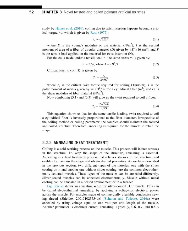
study by Haines et al. (2016), coiling due to twist insertion happens beyond a crit-
ical torque, τc, which is given by Ross (1977):
τc 5ffiffiffiffiffiffiffiffiffiffiffi
2EIFp
(3.1)
where E is the young’s modulus of the material (N/m2), I is the second
moment of area of a fiber of circular diameter (D) given by πD4=16 (m4), and F
is the tensile load applied on the material for twist insertion (N).
For the coils made under a tensile load F, the same stress σ, is given by:
σ5F=A; where A5πD2=4 (3.2)
Critical twist to coil, Tc is given by:
Tc 5τc
2πJG0 (3.3)
where Tc is the critical twist torque required for coiling (Turns/m), J is the
polar moment of inertia given by 5πD4=32 for a cylindrical fiber (m4), and G0is
the shear modulus of fiber material (N/m2).
Now combining (3.1) and (3.3) will give us the twist required to coil a fiber:
Tc 52
ffiffiffiffiffiffiffiffiffi
2σEp
πDG0 (3.4)
This equation shows us that for the same tensile loading, twist required to coil
a cylindrical fiber is inversely proportional to the fiber diameter. Irrespective of
the coiling method or coiling parameter, the samples should maintain the twisted
and coiled structure. Therefore, annealing is required for the muscle to retain the
shape.
3.2.3 ANNEALING (HEAT TREATMENT)
Coiling is a cold working process on the muscle. This process will induce stresses
in the structure. To keep the shape of the structure, annealing is essential.
Annealing is a heat treatment process that relieves stresses in the structure, and
enables to maintain the shape and obtain desired properties. As we have described
in the previous section, two different types of the muscles, one with the silver
coating on it and another one without silver coating, are the common electrother-
mally actuated muscles. These types of the muscles can be annealed differently.
Silver-coated muscles can be annealed electrothermally. Muscle without metal
coating can be annealed in a heated environment or in a furnace.
Fig. 3.2(i)d shows an annealing setup for silver-coated TCP muscle. This can
be called electrothermal annealing, by applying a voltage or electrical power
across the muscle. For muscles made of commercially available conductive sew-
ing thread (Shieldex 260151023534oz) (Saharan and Tadesse, 2016a) were
annealed by using voltage equal to one volt per unit length of the muscle.
Another parameter is electrical current annealing. Typically, 0.6, 0.7, and 0.8 A
52 CHAPTER 3 Novel twisted and coiled polymer artificial muscles
magnitude of the current can be used for electrothermal annealing of the 1-ply,
2-ply, and 3-ply muscles. Electrothermal annealing is mostly done in cycles.
Typically, 12 power cycles for 20�40 seconds are good enough depending on
material and number of plies.
The other approach is annealing in a furnace for bare precursor fiber. For
example, a coiled muscle fabricated using 400 μm nylon fishing line in a furnace
at 180�C for 90 minutes (Saharan and Tadesse, 2016b). Some researchers prefer
to anneal in a medium other than air. For example, Kianzad et al. (2015a) have
used nitrogen for annealing of the muscle. Nitrogen annealing is good, especially
in the case of silver-coated precursor fibers since nitrogen avoids the oxidation of
the silver on the muscle surface, which is directly related to the life and perfor-
mance of the muscle. The heat-treated structure needs to be trained for the
specific application and completes the fabrication process.
3.2.4 TRAINING
Training of the muscle is required to obtain reversible actuation cycle under a
load. Fig. 3.2(i)e shows the annealing process. For this purpose, the annealed
structure undergoes multiple on and off cycles for the amount of load for which it
is going to be used. For example, if the muscle is required to be used to open and
close a valve, it has a known amount of force required to open the valve. The
training load is also a function of spring index of the muscle. Monofilament,
nonsilver-coated muscles with comparatively larger diameter are stiffer and
require more force to obtain better coil spacing. So, the muscle can be trained on
a dead weight equal to the amount of force required to open and close the valve.
Another parameter to decide here is what kind of muscle are we using? If we are
using an electrothermal muscle, we need a power supply and a stop watch to train
the muscle. Another option could be a computer controlled power supply, which
can give electrical power cycles through a computer program. Muscle without
silver coating may require an arrangement for alternating hot and cold water
switching mechanism. Hot air blower can also be used but that would not be a
great option for control of the hot air flow and heat loss can potentially be an
issue. Once a particular method of training is selected, the number of cycles,
load, and magnitude of stimuli (voltage/hot fluid) are determined accordingly.
Some training cycles presented are as follows: 12�15 power cycles of training
with 50% duty cycle are sufficient for the training of the muscles (Saharan and
Tadesse, 2016a).
Another possible training method could be training under dynamic loadings
such as springs. Dynamic loading is a special case for loading since the force
keeps on increasing or decreasing with the displacement. For example, spring
force (F5 kx) is a function of the amount of extension of the spring. In such
cases, the muscles should be trained for the maximum amount of force required.
One of the training techniques yet to be explored is dynamic training. In dynamic
533.2 Detailed Fabrication of the Twisted and Coiled Polymeric Muscles
training, one can use a spring of variable stiffness or variable weight. Evidence of
such training is not present in the literature yet.
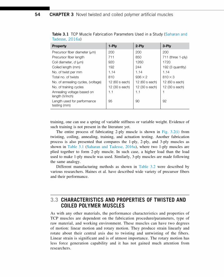
The entire process of fabricating 2-ply muscle is shown in Fig. 3.2(i) from
twisting, coiling, annealing, training, and actuation testing. Another fabrication
process is also presented that compares the 1-ply, 2-ply, and 3-ply muscles as
shown in Table 3.1 (Saharan and Tadesse, 2016a), where two 1-ply muscles are
plied together to form 2-ply muscle. In such case, a higher load than the load
used to make 1-ply muscle was used. Similarly, 3-ply muscles are made following
the same analogy.
Different manufacturing methods as shown in Table 3.2 were described by
various researchers. Haines et al. have described wide variety of precursor fibers
and their performance.
3.3 CHARACTERISTICS AND PROPERTIES OF TWISTED ANDCOILED POLYMER MUSCLES
As with any other materials, the performance characteristics and properties of
TCP muscles are dependent on the fabrication procedure/parameters, type of
raw material, and working environment. These muscles can have two degrees
of motion: linear motion and rotary motion. They produce strain linearly and
rotate about their central axis due to twisting and untwisting of the fibers.
Linear strain is significant and is of utmost importance. The rotary motion has
less force generation capability and it has not gained much attention from
researchers.
Table 3.1 TCP Muscle Fabrication Parameters Used in a Study (Saharan andTadesse, 2016a)
Property 1-Ply 2-Ply 3-Ply
Precursor fiber diameter (μm) 200 200 200Precursor fiber length 711 850 711 (three 1-ply)Coil diameter, d (μm) 920 1260 1720Coiled length (mm) 192 244 192 (3 quantity)No. of twist per mm 1.14 1.14 1.14Total no. of twists 810 93632 8103 3No. of annealing cycles, (voltage) 12 (60 s each) 12 (60 s each) 12 (60 s each)No. of training cycles 12 (30 s each) 12 (30 s each) 12 (30 s each)Annealing voltage based onlength (V/inch)
1.1 1.1 1
Length used for performancetesting (mm)
95 90 92
54 CHAPTER 3 Novel twisted and coiled polymer artificial muscles
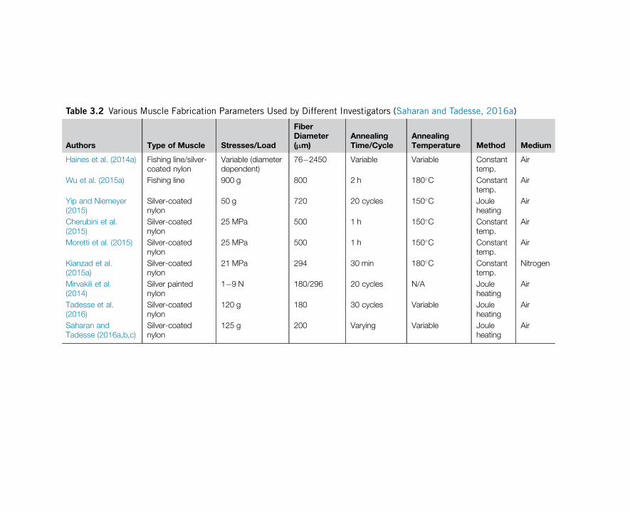
Table 3.2 Various Muscle Fabrication Parameters Used by Different Investigators (Saharan and Tadesse, 2016a)
Authors Type of Muscle Stresses/Load
FiberDiameter(µm)
AnnealingTime/Cycle
AnnealingTemperature Method Medium
Haines et al. (2014a) Fishing line/silver-coated nylon
Variable (diameterdependent)
76�2450 Variable Variable Constanttemp.
Air
Wu et al. (2015a) Fishing line 900 g 800 2 h 180�C Constanttemp.
Air
Yip and Niemeyer(2015)
Silver-coatednylon
50 g 720 20 cycles 150�C Jouleheating
Air
Cherubini et al.(2015)
Silver-coatednylon
25 MPa 500 1 h 150�C Constanttemp.
Air
Moretti et al. (2015) Silver-coatednylon
25 MPa 500 1 h 150�C Constanttemp.
Air
Kianzad et al.(2015a)
Silver-coatednylon
21 MPa 294 30 min 180�C Constanttemp.
Nitrogen
Mirvakili et al.(2014)
Silver paintednylon
1�9 N 180/296 20 cycles N/A Jouleheating
Air
Tadesse et al.(2016)
Silver-coatednylon
120 g 180 30 cycles Variable Jouleheating
Air
Saharan andTadesse (2016a,b,c)
Silver-coatednylon
125 g 200 Varying Variable Jouleheating
Air
The linear strain is also a function of the type of chirality of the muscle. As
discussed in the earlier section, the homochiral muscles would show linear con-
traction whereas heterochiral muscles would show linear expansion. Both types of
linear strains have their importance and application in the biomedical and soft
robotics fields. Important characteristics of artificial muscles are stress generation
or force, strain or displacement, input power, output energy or power, efficiency,
frequency of operation, life cycle, repeatability, and cost. Most of these para-
meters are quantified and we will present here some results presented in the litera-
ture. We also discussed how these parameters are measured to synchronize with
other input stimuli such temperature to understand the muscles. Time domain
stress and strain have been measured by some researchers (Saharan and Tadesse,
2016a; Tadesse et al., 2016; Haines et al., 2014a; Wu et al., 2016a) in literature.
We will discuss here strain and force measurement for the 2-ply and 3-ply
muscles.
The key characteristic curves of TCP muscles are shown in Fig. 3.2(ii). A
square wave voltage is shown in Fig. 3.2(ii)a for electrically actuated TCP mus-
cles with starting time ta and end time tb, the corresponding outputs of the muscle
(displacement, force, and temperature) will have a profile as shown in Fig. 3.2(ii)b.
The magnitudes will increase until the voltage is turned off at tb; this is the
heating phase of the muscle. Then, the profile starts decreasing until time tc; this
is the cooling phase. Fig. 3.2(ii)c shows a typical plot of tensile actuation versus
temperature plot compared with SMA actuators that have large hysteresis.
Fig. 3.2(ii)d is the output displacement or strain versus frequency. The decrease
in strain at high frequency is common to all smart materials. Another characteris-
tic curve is the tensile actuation versus nominal applied stress. Fig. 3.2(ii)e shows
an increase at the initial stage and relatively constant tensile actuation afterwards
as the applied load is increased. This tensile actuation is based on the normaliza-
tion with respect to loaded length. The loaded length is increasing as the applied
load is stretching the material axially. Fig. 3.2(ii)f shows a characteristic curve
where the initial length for tensile actuation is nonloaded length. In this case, the
tensile actuation versus applied load increases initially and decreases at optimum
applied load. Note that the nonloaded length is shorter than the loaded length; as
a result the strain magnitude will be different for the two cases.
The profiles shown in Fig. 3.2(ii) are based on the current development of the
materials and some of the measurement can be done to determine properties under
different circumstances. We will discuss displacement/strain, force/stress, fre-
quency, and microscope images of the TCP muscles.
3.3.1 STRAIN AND FORCE MEASUREMENT
Strain is the ratio of the change in length to the original length of an actuator. It
is often expressed in percentage. There are two different types of strain measure-
ment, under a constant load measurement or under a variable load. Fig. 3.2(iii)a
shows the experimental setup for the strain measurement under the constant
56 CHAPTER 3 Novel twisted and coiled polymer artificial muscles
loading and Fig. 3.2(iii)b is the strain under variable load or spring. The setup
includes displacement sensor, load cell, power supply, linear guide for initial pre-
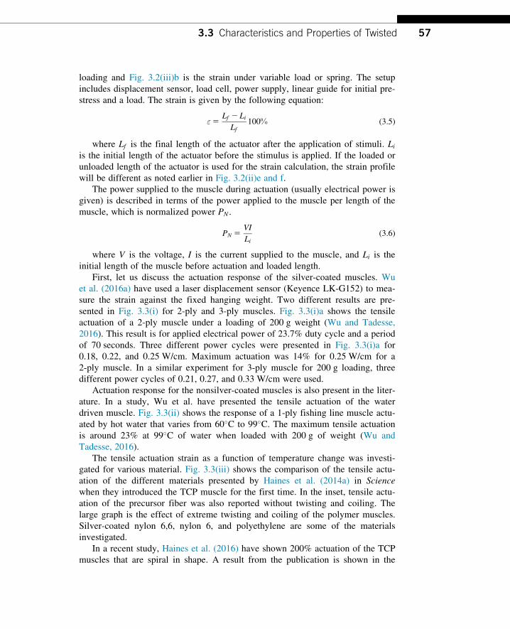
stress and a load. The strain is given by the following equation:
ε5Lf 2 Li
Lf100% (3.5)
where Lf is the final length of the actuator after the application of stimuli. Liis the initial length of the actuator before the stimulus is applied. If the loaded or
unloaded length of the actuator is used for the strain calculation, the strain profile
will be different as noted earlier in Fig. 3.2(ii)e and f.
The power supplied to the muscle during actuation (usually electrical power is
given) is described in terms of the power applied to the muscle per length of the
muscle, which is normalized power PN .
PN 5VI
Li(3.6)
where V is the voltage, I is the current supplied to the muscle, and Li is the
initial length of the muscle before actuation and loaded length.
First, let us discuss the actuation response of the silver-coated muscles. Wu
et al. (2016a) have used a laser displacement sensor (Keyence LK-G152) to mea-
sure the strain against the fixed hanging weight. Two different results are pre-
sented in Fig. 3.3(i) for 2-ply and 3-ply muscles. Fig. 3.3(i)a shows the tensile
actuation of a 2-ply muscle under a loading of 200 g weight (Wu and Tadesse,
2016). This result is for applied electrical power of 23.7% duty cycle and a period
of 70 seconds. Three different power cycles were presented in Fig. 3.3(i)a for
0.18, 0.22, and 0.25 W/cm. Maximum actuation was 14% for 0.25 W/cm for a
2-ply muscle. In a similar experiment for 3-ply muscle for 200 g loading, three
different power cycles of 0.21, 0.27, and 0.33 W/cm were used.
Actuation response for the nonsilver-coated muscles is also present in the liter-
ature. In a study, Wu et al. have presented the tensile actuation of the water
driven muscle. Fig. 3.3(ii) shows the response of a 1-ply fishing line muscle actu-
ated by hot water that varies from 60�C to 99�C. The maximum tensile actuation
is around 23% at 99�C of water when loaded with 200 g of weight (Wu and
Tadesse, 2016).
The tensile actuation strain as a function of temperature change was investi-
gated for various material. Fig. 3.3(iii) shows the comparison of the tensile actu-
ation of the different materials presented by Haines et al. (2014a) in Science
when they introduced the TCP muscle for the first time. In the inset, tensile actu-
ation of the precursor fiber was also reported without twisting and coiling. The
large graph is the effect of extreme twisting and coiling of the polymer muscles.
Silver-coated nylon 6,6, nylon 6, and polyethylene are some of the materials
investigated.
In a recent study, Haines et al. (2016) have shown 200% actuation of the TCP
muscles that are spiral in shape. A result from the publication is shown in the
573.3 Characteristics and Properties of Twisted
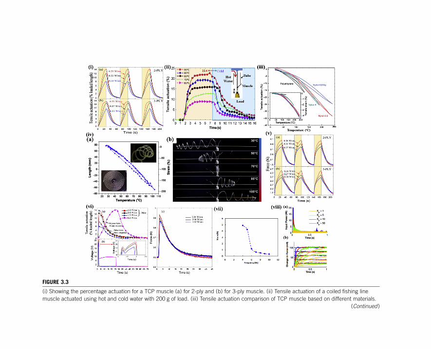
FIGURE 3.3
(i) Showing the percentage actuation for a TCP muscle (a) for 2-ply and (b) for 3-ply muscle. (ii) Tensile actuation of a coiled fishing line
muscle actuated using hot and cold water with 200 g of load. (iii) Tensile actuation comparison of TCP muscle based on different materials.
(Continued)
� Inset is the comparison of actuation of the different precursor fiber. (iv) Twist on artificial muscle shows the 200% tensile actuation of a TCP
muscle: (a) strain versus temperature and (b) optical picture of the muscle when actuated electrically. (v) Force measurement for three
power cycles obtained from a Futek load cell (LBS-200) under the loading of an extension spring: (a) for 2-ply muscle; (b) for 3-ply muscle.
(vi) Results for a pulsed actuation experiments using three different power cycles: (a) tensile actuation in comparison with a square wave
actuation; (b) voltage input; (c) force response for similar power input cycles. (vii) The frequency response of silver plated sew thread TCP
under a load of 25 MPa. (viii) Effect of closed loop controller on the TCP muscle: (a) input power and (b) change in force.
Figure adapted from (i) Wu, L., Jung De andrade, M., Saharan, L., Rome, R., Baughman, R.H., Tadesse, Y., 2016a. Compact and low-cost humanoid hand powered by
nylon artificial muscles. Bioinspirat. Biomim. (submitted). (ii) Wu, L., De andrade, M.J., Rome, R.S., Haines, C., Lima, M.D., Baughman, R.H., et al., 2015a. Nylon-
muscle-actuated robotic finger. In: SPIE Smart Structures and Materials1Nondestructive Evaluation and Health Monitoring, International Society for Optics and
Photonics, 94310I-94310I-12. (iii) Haines, C.S., Lima, M.D., Li, N., Spinks, G.M., Foroughi, J., Madden, J.D., et al., 2014a. Artificial muscles from fishing line and
sewing thread. Science 343, 868�872. (iv) Haines, C.S., Li, N., Spinks, G.M., Aliev, A.E., Di, J., Baughman, R.H., 2016. New twist on artificial muscles. Proc. Natl
Acad. Sci., 201605273. (v) Wu, L., Jung De andrade, M., Saharan, L., Rome, R., Baughman, R.H., Tadesse, Y., 2016a. Compact and low-cost humanoid hand powered
by nylon artificial muscles. Bioinspirat. Biomim. (submitted). (vi) Wu, L., Jung De andrade, M., Saharan, L., Rome, R., Baughman, R.H., Tadesse, Y., 2016a. Compact
and low-cost humanoid hand powered by nylon artificial muscles. Bioinspirat. Biomim. (submitted). (vii) Mirvakili, S.M., Ravandi, A.R., Hunter, I.W., Haines, C.S., Li, N.,
Foroughi, J., et al., 2014. Simple and strong: twisted silver painted nylon artificial muscle actuated by Joule heating. In: SPIE Smart Structures and
Materials1Nondestructive Evaluation and Health Monitoring, International Society for Optics and Photonics, 90560I-90560I-10. (viii) Yip, M.C., Niemeyer, G., 2015.
High-performance robotic muscles from conductive nylon sewing thread. In: Robotics and Automation (ICRA), 2015 IEEE International Conference on. IEEE, pp.
2313�2318.
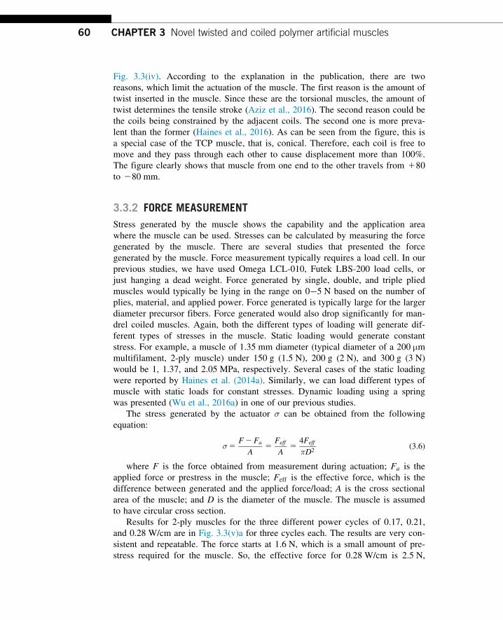
Fig. 3.3(iv). According to the explanation in the publication, there are two
reasons, which limit the actuation of the muscle. The first reason is the amount of
twist inserted in the muscle. Since these are the torsional muscles, the amount of
twist determines the tensile stroke (Aziz et al., 2016). The second reason could be
the coils being constrained by the adjacent coils. The second one is more preva-
lent than the former (Haines et al., 2016). As can be seen from the figure, this is
a special case of the TCP muscle, that is, conical. Therefore, each coil is free to
move and they pass through each other to cause displacement more than 100%.
The figure clearly shows that muscle from one end to the other travels from 180
to 280 mm.
3.3.2 FORCE MEASUREMENT
Stress generated by the muscle shows the capability and the application area
where the muscle can be used. Stresses can be calculated by measuring the force
generated by the muscle. There are several studies that presented the force
generated by the muscle. Force measurement typically requires a load cell. In our
previous studies, we have used Omega LCL-010, Futek LBS-200 load cells, or
just hanging a dead weight. Force generated by single, double, and triple plied
muscles would typically be lying in the range on 0�5 N based on the number of
plies, material, and applied power. Force generated is typically large for the larger
diameter precursor fibers. Force generated would also drop significantly for man-
drel coiled muscles. Again, both the different types of loading will generate dif-
ferent types of stresses in the muscle. Static loading would generate constant
stress. For example, a muscle of 1.35 mm diameter (typical diameter of a 200 μmmultifilament, 2-ply muscle) under 150 g (1.5 N), 200 g (2 N), and 300 g (3 N)
would be 1, 1.37, and 2.05 MPa, respectively. Several cases of the static loading
were reported by Haines et al. (2014a). Similarly, we can load different types of
muscle with static loads for constant stresses. Dynamic loading using a spring
was presented (Wu et al., 2016a) in one of our previous studies.
The stress generated by the actuator σ can be obtained from the following
equation:
σ5F2Fa
A5
Feff
A5
4Feff
πD2(3.6)
where F is the force obtained from measurement during actuation; Fa is the
applied force or prestress in the muscle; Feff is the effective force, which is the
difference between generated and the applied force/load; A is the cross sectional
area of the muscle; and D is the diameter of the muscle. The muscle is assumed
to have circular cross section.
Results for 2-ply muscles for the three different power cycles of 0.17, 0.21,
and 0.28 W/cm are in Fig. 3.3(v)a for three cycles each. The results are very con-
sistent and repeatable. The force starts at 1.6 N, which is a small amount of pre-
stress required for the muscle. So, the effective force for 0.28 W/cm is 2.5 N,
60 CHAPTER 3 Novel twisted and coiled polymer artificial muscles
which is highest for this power density. Similarly, results for 3-ply muscle, the
force is shown in Fig. 3.3(v)b. A slightly higher prestress of 1.7 N was used to
obtain approximately 3.1 N of force. If we compare the 0.28 and 0.27 W/cm
applied power for the 2-ply and 3-ply muscles from the figure, we can conclude
that 2-ply has generated the slightly higher force for the same power. Hence, we
can conclude that 2-ply muscles are more efficient than 3-ply muscle.
3.3.3 FREQUENCY MEASUREMENT AND PULSED ACTUATION
Typically, results reported in the literature have shown the slow frequency
response of the TCP muscles. Since these muscles work on heat transfer, theo-
retically and practically the frequency is limited by how fast they are heated
and cooled. High-temperature pulses and forced cooling can provide a high fre-
quency of actuation. In their initial study Haines et al. (2014a) showed the
response of nonsilver-coated muscle at 1 Hz by switching the hot and cold
water alternatively. In the same study, authors reported silver-coated muscles
actuation at 5 Hz when submerged in water. In our study, which was described
in the previous section (Wu et al., 2016a), we studied the higher frequency of
response in the muscle where actuation required 1 second of an electrical pulse
on a 2-ply muscle at 50 g weight. Results for the strain and force response are
shown in Fig.3.3(vi).
Fig. 3.3(vi) shows the result of the response of three distinct power cycles of
1.75, 2.01, and 2.15 W/cm for 1 second. The 2.15 W/cm power cycle has the
same response as 0.25 W/cm for a longer period. The voltage waveform of the
muscle input can also be observed from the figure. It shows some change in resis-
tance due to pulse input. The force response of the muscle is also given in
Fig. 3.3(vi)c. This pulsed actuation force measurement was performed for
dynamic loading. We can observe from the figure a significant decrease in the
muscle performance regarding force generation.
In a different study, Mirvakili et al. have shown the high-frequency response
of the silver-coated sewing thread based TCP muscle as shown in Fig. 3.3(vii).
Authors tested the muscle for 5�10 Hz to show the frequency response of the
muscle to a pulse of 45 V. We can see from the figure how the frequency
response of the muscle has decreased significantly at 6 Hz. Strain becomes almost
zero for 10 Hz. In another study, following feedback control theory, Yip and
Niemeyer (2015) showed that the response time of such actuator (the authors
called them SCPs) can surpass that of skeletal muscle. They showed a 28-ms
response time for a feedback gain of 50 as shown in Fig. 3.3(viii) (blue).
3.3.4 MICROSCOPY
Microscopic images will help us in understanding of the structure and shape of
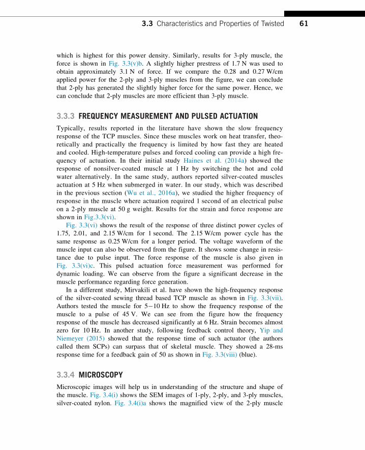
the muscle. Fig. 3.4(i) shows the SEM images of 1-ply, 2-ply, and 3-ply muscles,
silver-coated nylon. Fig. 3.4(i)a shows the magnified view of the 2-ply muscle
613.3 Characteristics and Properties of Twisted
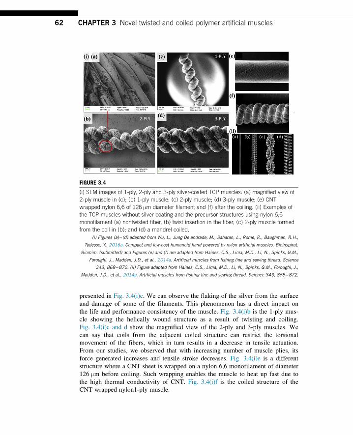
presented in Fig. 3.4(i)c. We can observe the flaking of the silver from the surface
and damage of some of the filaments. This phenomenon has a direct impact on
the life and performance consistency of the muscle. Fig. 3.4(i)b is the 1-ply mus-
cle showing the helically wound structure as a result of twisting and coiling.
Fig. 3.4(i)c and d show the magnified view of the 2-ply and 3-ply muscles. We
can say that coils from the adjacent coiled structure can restrict the torsional
movement of the fibers, which in turn results in a decrease in tensile actuation.
From our studies, we observed that with increasing number of muscle plies, its
force generated increases and tensile stroke decreases. Fig. 3.4(i)e is a different
structure where a CNT sheet is wrapped on a nylon 6,6 monofilament of diameter
126 μm before coiling. Such wrapping enables the muscle to heat up fast due to
the high thermal conductivity of CNT. Fig. 3.4(i)f is the coiled structure of the
CNT wrapped nylon1-ply muscle.
FIGURE 3.4
(i) SEM images of 1-ply, 2-ply and 3-ply silver-coated TCP muscles: (a) magnified view of
2-ply muscle in (c); (b) 1-ply muscle; (c) 2-ply muscle; (d) 3-ply muscle; (e) CNT
wrapped nylon 6,6 of 126 μm diameter filament and (f) after the coiling. (ii) Examples of
the TCP muscles without silver coating and the precursor structures using nylon 6,6
monofilament (a) nontwisted fiber, (b) twist insertion in the fiber, (c) 2-ply muscle formed
from the coil in (b); and (d) a mandrel coiled.
(i) Figures (a)�(d) adapted from Wu, L., Jung De andrade, M., Saharan, L., Rome, R., Baughman, R.H.,
Tadesse, Y., 2016a. Compact and low-cost humanoid hand powered by nylon artificial muscles. Bioinspirat.
Biomim. (submitted) and Figures (e) and (f) are adapted from Haines, C.S., Lima, M.D., Li, N., Spinks, G.M.,
Foroughi, J., Madden, J.D., et al., 2014a. Artificial muscles from fishing line and sewing thread. Science
343, 868�872. (ii) Figure adapted from Haines, C.S., Lima, M.D., Li, N., Spinks, G.M., Foroughi, J.,
Madden, J.D., et al., 2014a. Artificial muscles from fishing line and sewing thread. Science 343, 868�872.
62 CHAPTER 3 Novel twisted and coiled polymer artificial muscles
The structures of the nylon 6,6 monofilament fiber (Fig. 3.4(ii)a) and TCP
muscles without silver coating (Fig. 3.4(ii)b�d) (bare nylon) are illustrated in
Fig. 3.4(ii) using optical imaging. We can see the difference in coil spacing
between self-coiled (Fig. 3.4(ii)b) and mandrel coiled (Fig. 3.4(ii)d) muscles. The
latter have large spacing between coils compared to the former. Such coils have a
large axial contraction (B49% in some cases). Fig. 3.4(ii)c shows an optical
image of 2-ply muscle.
3.4 BIOMEDICAL APPLICATIONS OF TWISTED AND COILEDPOLYMER
The TCP muscles are getting a number of applications in biomedical, orthotics,
prosthetics, and medical textiles. Some of these applications have been explored
and presented in the literature. Some potential applications are yet to be discov-
ered. Other smart materials that received attention for biomedical and robotics
applications are electroactive polymers (Carpi and Smela, 2009). The most widely
explored application of TCP muscle is in prosthetic hands since these actuators
are comparable to SMAs that have been explored for biomedical applications
(Yoneyama and Miyazaki, 2008).
3.4.1 PROSTHETIC HANDS
There are a large number of amputees living across the globe. Most of them can-
not afford the expensive prostheses, such as myoelectric prostheses, which cost
somewhere between $20,000 and $100,000 (McGimpsey and Bradford, 2008; van
der Riet et al., 2013). As described by Haines et al. (2014a) the TCP actuators
have a tensile stroke more than mammalian muscles (B20%). Hence, we can
design a device based on these muscles that can help improve the life of ampu-
tees. Biomimetic design can help restore all kinds of prehensile and nonprehensile
movements of the hand. Prehensile motions are related to wrapping the hand
around objects and grasping whereas nonprehensile motions are mostly gestures
and movements that do not involve holding and grasping of the objects. Before
understanding the design of prosthetic hands, let us understand the anatomy of the
hand.
Human hand grasping and gripping: The natural human hand is comprised of
bones and muscles. Wrapping, holding, and grasping of an object is termed as a
prehensile movement. There are six different types of prehensile movements
(Taylor and Schwarz, 1955): (1) cylindrical: thumb and finger wrap around a
cylindrical object such as glass or pipe; (2) hook (snap): grasping something using
fingers only without using palm or thumb, for example, holding and pulling a
door handle; (3) tip pinch: holding by the type of thumb tip by pressing some-
thing against the tip of other fingers, for example, holding a screw head; (4)
633.4 Biomedical Applications of Twisted and Coiled Polymer
palmar: grasping something with curled fingers and palm, for example, holding a
brush; (5) spherical grasp: holding something against finger and thumb pads such
as a ball; (6) lateral grip: holding something using thumb and index finger such
as holding a key.
Human hand description: The human hand is made up of four fingers and a
thumb. The human hand contains 27 bones (ElKoura and Singh, 2003, Taylor and
Schwarz, 1955). Finger bones are called phalanges and these facilitate flex-
ion�extension and abduction�adduction motion. Flexion motion refers to the
bending or curling of the finger to take some shape. Extension motion is the
returning of the flexed finger to rest position. Abduction and adduction motion is
defined by left and right movement from the midline of the finger. Finger phalan-
ges are termed as the distal, the middle, and the proximal phalange. The thumb
has five degrees of freedom (DoF), one for interphalangeal joint, two for metacar-
pophalangeal (MCP) and two for carpometacarpal joint. The other four fingers all
have three joints and four degrees of freedom. The MCP joint has two DoF,
which includes abduction and adduction motion. The other two distal interphalan-
geal and the proximal interphalangeal have one DoF each. Due to its five DoF,
the thumb can reach each finger to facilitate precision grip.
In one of our recent studies (Arjun et al., 2016), we showed a completely
customizable and 3D printable prosthetic hand (Fig. 3.5(i)) that was designed
and developed using TCP muscles. The cost of the complete device was around
$170 excluding the electronics. The key advantages of the TCP muscles are
their low material cost (as low as $5/kg) compared with SMA (more than
$3000/kg) and the low hysteresis (1.2�C for TCP and 27�C for SMA). The pros-
thetic hand was tested extensively and was able to grasp all sorts of daily used
objects. The prototype was of an adult size human hand. This hand used bead-
ing wire routed through guides to the wrist via palm. Then, the tendons were
connected with the TCP muscle in the palm. Since the 3D printed plastic parts
had hard surface, which causes slippage of the objects during handling, a sili-
cone coating on the finger pads was added to improve grasping. The device was
designed in SolidWorks and could be easily 3D printed and assembled. The 3D
printed structure was very light in weight and easily customizable depending on
the need (the notion of personalized medicine). The prosthetic hand design used
brass pulleys to accommodate longer muscle lengths. All the above made
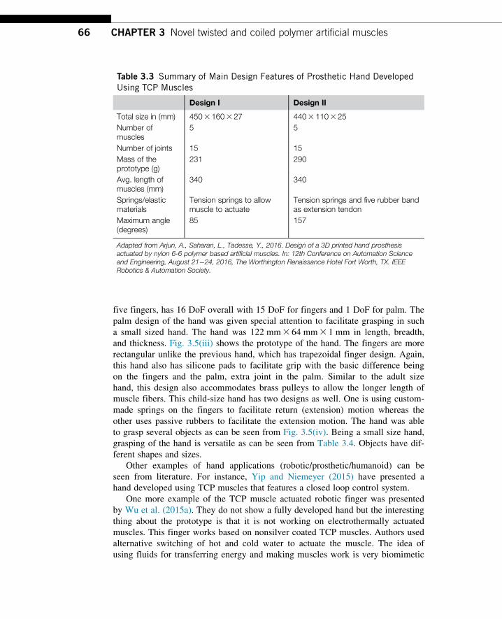
the prosthetic device ergonomic. Parameters for the prototypes are given in
Table 3.3.
Grasping experiments of the prosthetic hand were also done using trials of
objects of different shapes and sizes and are shown in Fig. 3.5(ii). This hand can
help improving the quality of life of the millions of the amputees worldwide and
can be a viable alternative to all those expensive prosthetic devices.
Another example of the prosthetic/humanoid/robotic hand was presented in
one of our recent studies (Wu et al., 2016a). This hand mimics a 7-year-old
child’s hand and it was also developed using the TCP muscles. It is a
suitable alternative for child amputees. This lightweight and compact hand has
64 CHAPTER 3 Novel twisted and coiled polymer artificial muscles
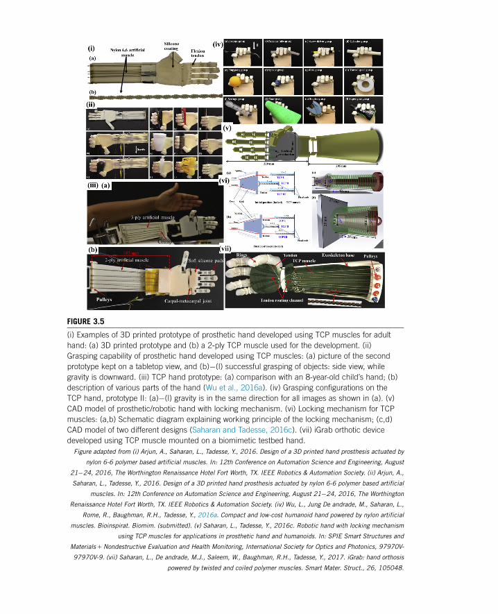
FIGURE 3.5
(i) Examples of 3D printed prototype of prosthetic hand developed using TCP muscles for adult
hand: (a) 3D printed prototype and (b) a 2-ply TCP muscle used for the development. (ii)
Grasping capability of prosthetic hand developed using TCP muscles: (a) picture of the second
prototype kept on a tabletop view, and (b)�(l) successful grasping of objects: side view, while
gravity is downward. (iii) TCP hand prototype: (a) comparison with an 8-year-old child’s hand; (b)
description of various parts of the hand (Wu et al., 2016a). (iv) Grasping configurations on the
TCP hand, prototype II: (a)�(l) gravity is in the same direction for all images as shown in (a). (v)
CAD model of prosthetic/robotic hand with locking mechanism. (vi) Locking mechanism for TCP
muscles: (a,b) Schematic diagram explaining working principle of the locking mechanism; (c,d)
CAD model of two different designs (Saharan and Tadesse, 2016c). (vii) iGrab orthotic device
developed using TCP muscle mounted on a biomimetic testbed hand.
Figure adapted from (i) Arjun, A., Saharan, L., Tadesse, Y., 2016. Design of a 3D printed hand prosthesis actuated by
nylon 6-6 polymer based artificial muscles. In: 12th Conference on Automation Science and Engineering, August
21�24, 2016, The Worthington Renaissance Hotel Fort Worth, TX. IEEE Robotics & Automation Society. (ii) Arjun, A.,
Saharan, L., Tadesse, Y., 2016. Design of a 3D printed hand prosthesis actuated by nylon 6-6 polymer based artificial
muscles. In: 12th Conference on Automation Science and Engineering, August 21�24, 2016, The Worthington
Renaissance Hotel Fort Worth, TX. IEEE Robotics & Automation Society. (iv) Wu, L., Jung De andrade, M., Saharan, L.,
Rome, R., Baughman, R.H., Tadesse, Y., 2016a. Compact and low-cost humanoid hand powered by nylon artificial
muscles. Bioinspirat. Biomim. (submitted). (v) Saharan, L., Tadesse, Y., 2016c. Robotic hand with locking mechanism
using TCP muscles for applications in prosthetic hand and humanoids. In: SPIE Smart Structures and
Materials1Nondestructive Evaluation and Health Monitoring, International Society for Optics and Photonics, 97970V-
97970V-9. (vii) Saharan, L., De andrade, M.J., Saleem, W., Baughman, R.H., Tadesse, Y., 2017. iGrab: hand orthosis
powered by twisted and coiled polymer muscles. Smart Mater. Struct., 26, 105048.
five fingers, has 16 DoF overall with 15 DoF for fingers and 1 DoF for palm. The
palm design of the hand was given special attention to facilitate grasping in such
a small sized hand. The hand was 122 mm3 64 mm3 1 mm in length, breadth,
and thickness. Fig. 3.5(iii) shows the prototype of the hand. The fingers are more
rectangular unlike the previous hand, which has trapezoidal finger design. Again,
this hand also has silicone pads to facilitate grip with the basic difference being
on the fingers and the palm, extra joint in the palm. Similar to the adult size
hand, this design also accommodates brass pulleys to allow the longer length of
muscle fibers. This child-size hand has two designs as well. One is using custom-
made springs on the fingers to facilitate return (extension) motion whereas the
other uses passive rubbers to facilitate the extension motion. The hand was able
to grasp several objects as can be seen from Fig. 3.5(iv). Being a small size hand,
grasping of the hand is versatile as can be seen from Table 3.4. Objects have dif-
ferent shapes and sizes.
Other examples of hand applications (robotic/prosthetic/humanoid) can be
seen from literature. For instance, Yip and Niemeyer (2015) have presented a
hand developed using TCP muscles that features a closed loop control system.
One more example of the TCP muscle actuated robotic finger was presented
by Wu et al. (2015a). They do not show a fully developed hand but the interesting
thing about the prototype is that it is not working on electrothermally actuated
muscles. This finger works based on nonsilver coated TCP muscles. Authors used
alternative switching of hot and cold water to actuate the muscle. The idea of
using fluids for transferring energy and making muscles work is very biomimetic
Table 3.3 Summary of Main Design Features of Prosthetic Hand DevelopedUsing TCP Muscles
Design I Design II
Total size in (mm) 45031603 27 4403 110325Number ofmuscles
5 5
Number of joints 15 15Mass of theprototype (g)
231 290
Avg. length ofmuscles (mm)
340 340
Springs/elasticmaterials
Tension springs to allowmuscle to actuate
Tension springs and five rubber bandas extension tendon
Maximum angle(degrees)
85 157
Adapted from Arjun, A., Saharan, L., Tadesse, Y., 2016. Design of a 3D printed hand prosthesisactuated by nylon 6-6 polymer based artificial muscles. In: 12th Conference on Automation Scienceand Engineering, August 21�24, 2016, The Worthington Renaissance Hotel Fort Worth, TX. IEEERobotics & Automation Society.
66 CHAPTER 3 Novel twisted and coiled polymer artificial muscles

in nature. Again, as we have described earlier, the only drawback for the device
is the energy efficiency. The efficiency of the muscle is close to 1%. To tackle
the issue, we need to add some device or mechanics that can save energy. In
one of our studies, we have developed a prosthetic hand with locking mecha-
nism. We showed a study (Saharan and Tadesse, 2016c) that was mostly based
on design and characterization of a prosthetic hand with energy efficiency.
Fig. 3.5(v) shows the CAD design of the prosthetic hand with locking
mechanism.
Like the human hand, TCP muscles also need a continuous supply of energy
to maintain a certain position. For example, if we are holding a cup of tea, the
muscles need to keep feeding power to hold the cup. A smarter solution can be
designing a locking mechanism, which can maintain the final position until asked
to release it. The locking mechanism can be designed for retaining a certain posi-
tion for the manipulator to save energy. Fig. 3.5(vi) shows the two different
designs of the locking mechanism that were presented in Saharan and Tadesse
(2016c).
There are two different designs of the locking mechanism. The first one is
thin but longer in length, whereas the second one is slightly thicker but the length
is half of the original device. The working mechanism of both the locking
mechanisms is the same. The device is essentially made up of three parts: a cone,
a shell, and a spring. The spring holds the cone in the hollow shell and keeps it
pressing against the shell walls. Therefore, when tendons are routed through the
shell, the cone will squeeze the tendon. The cone with the help of spring exerts
enough pressure on the tendons to hold their position. The schematic diagram in
Fig. 3.5(vi)c and d shows the working of the locking mechanism. From Fig. 3.5
(vi)a and b, we can see three different TCP muscles. TCP I and TCP III are the
extensor and flexor muscles for the prosthetic/robotic hand. These two muscles
can be powered on and off to move the finger in the desired direction. TCP II is
the muscle that can control the locking and unlocking position of the mechanism.
Table 3.4 The Various Objects the TCP Hand Could Grasp
NameSiliconeTube
ScrewDriver
PingPong Ball Sphere Disk
Mass (g) 8.0 7.0 2.7 0.5 4.5Size (mm) L5115,
D5 10L5 110 D5 40 D5 22 D5 60,
T56Name Thread
poolSyringe Cone Stapler Super glue
Mass (g) 33.0 14.0 4.0 38.0 26.0Size (mm) D5 56,
T5 20L5 125,D5 21
Dmax 5 8,Dmin 5 26,H5155
L3W3H5 603 333 46 L3W3H:133 443 63
L, length; W, width; H, height; T, thickness; D, diameter.
673.4 Biomedical Applications of Twisted and Coiled Polymer
The authors have performed experiments on the locking mechanism to show the
efficacy of the mechanism. This locking mechanism works well up to 4N of
force. Another possible case for locking mechanism development could be a
ratchet mechanism that is yet to be explored for this muscle.
3.4.2 ORTHOTIC HAND
Orthotic devices or wearable robotic systems are devices that help people with
muscular disorders restore their body part functions. There are millions of people
across the globe who have lost their motor ability due to neural disorders, acci-
dents, or strokes. Researchers are working on a wide variety of orthotic devices
such as hand, arms shoulder, foot, hip, and back. Orthotic devices are meant to
improve the quality of life of the affected people. Traditionally most of the
orthotic devices rely on DC motors, and pneumatic and hydraulic actuators. Some
researchers have tried using SMA as an alternate. Not to mention, most of these
conventional methods are heavy and/or costly. In our recent study (Saharan et al.,
2017), we used TCP muscle for the development of ergonomic orthotic devices,
which is light in weight, and customizable based on the need (Fig. 3.5(vii)). An
orthotic device for wrist was also designed and studied recently by Sutton et al.
(2016) and Sharma et al. (2017).
3.4.3 FECAL INCONTINENCE TREATMENT
Fecal incontinence (FI) is the involuntary loss of bowel contents or unintentional
loss of stool due to muscle disorders. This is a muscle disorder that could be
caused due to age related or neural disorders. This can cause stigma and affect
the quality of life for the affected person. According to Fattorini et al. (2016),
about 45% of retired people are affected by this disease. FI can be treated using
artificial sphincter implant. Naturally, the FI can be dealt with by external anal
sphincter muscle (EAS). According to Fattoini’s recent study, most of the artifi-
cial sphincters are not able to provide a complete solution. Hence, we can see that
currently there is no proper solution to the problem. TCP muscles might be used
to design such a device.
3.4.4 VARIABLE STIFFNESS ACTUATORS
Human muscles ability to vary stiffness helps in walking and catching actions
(Kianzad et al., 2015b). Variable stiffness structures can mimic the controllable
stiffness property of the natural muscle. Such structures can help developing pros-
thetics and orthotic devices for a human arm and leg. Most of the current actuators
cannot vary their stiffness while recruiting in the assistive devices. Hence, the
device cannot fully replicate the natural motion of the limb. Kianzad et al. devel-
oped a variable stiffness actuator (VSA), like a pinnate muscle by recruiting TCP
muscles at an angle of 20 degrees from central tendon as shown in Fig. 3.6(i).
68 CHAPTER 3 Novel twisted and coiled polymer artificial muscles
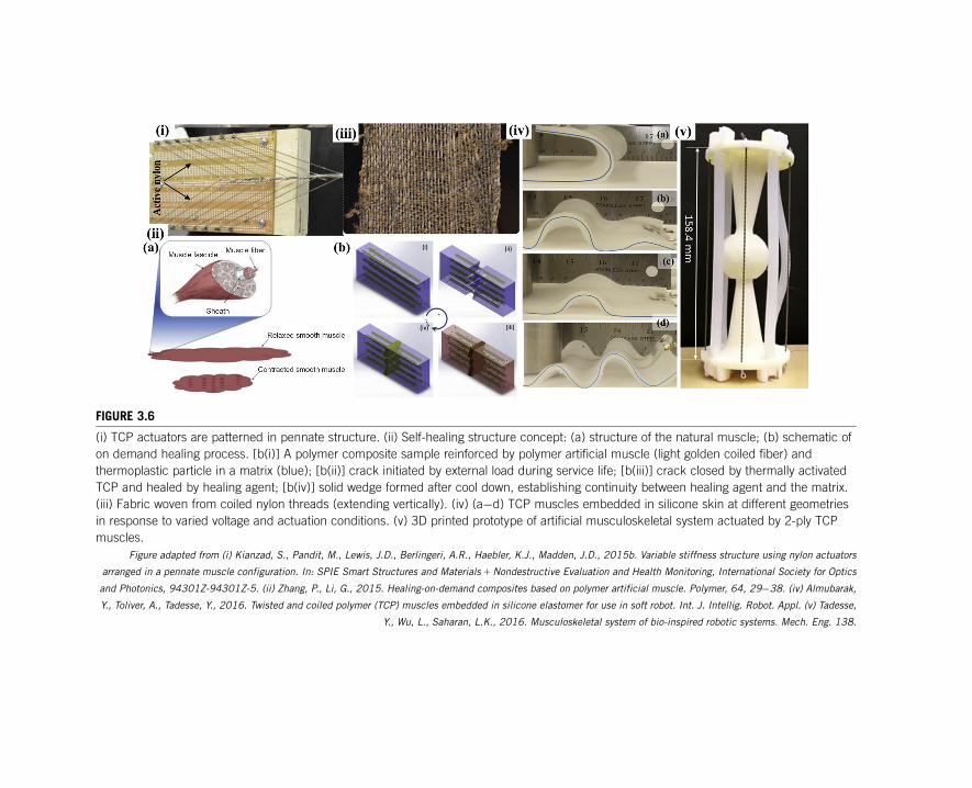
FIGURE 3.6
(i) TCP actuators are patterned in pennate structure. (ii) Self-healing structure concept: (a) structure of the natural muscle; (b) schematic of
on demand healing process. [b(i)] A polymer composite sample reinforced by polymer artificial muscle (light golden coiled fiber) and
thermoplastic particle in a matrix (blue); [b(ii)] crack initiated by external load during service life; [b(iii)] crack closed by thermally activated
TCP and healed by healing agent; [b(iv)] solid wedge formed after cool down, establishing continuity between healing agent and the matrix.
(iii) Fabric woven from coiled nylon threads (extending vertically). (iv) (a�d) TCP muscles embedded in silicone skin at different geometries
in response to varied voltage and actuation conditions. (v) 3D printed prototype of artificial musculoskeletal system actuated by 2-ply TCP
muscles.
Figure adapted from (i) Kianzad, S., Pandit, M., Lewis, J.D., Berlingeri, A.R., Haebler, K.J., Madden, J.D., 2015b. Variable stiffness structure using nylon actuators
arranged in a pennate muscle configuration. In: SPIE Smart Structures and Materials1Nondestructive Evaluation and Health Monitoring, International Society for Optics
and Photonics, 94301Z-94301Z-5. (ii) Zhang, P., Li, G., 2015. Healing-on-demand composites based on polymer artificial muscle. Polymer, 64, 29�38. (iv) Almubarak,
Y., Toliver, A., Tadesse, Y., 2016. Twisted and coiled polymer (TCP) muscles embedded in silicone elastomer for use in soft robot. Int. J. Intellig. Robot. Appl. (v) Tadesse,
Y., Wu, L., Saharan, L.K., 2016. Musculoskeletal system of bio-inspired robotic systems. Mech. Eng. 138.
Pennate muscles are those that can produce higher force and low displacement.
These muscles will be joining the central tendon at an angle.
The artificial VSA structure contains 16 muscles, as seen in Fig. 3.6(i). These
muscles are actuated using pulse width modulation (PWM). Results show that
stiffness of the structure can be varied from 503 N/m at a resonance frequency of
1.4 Hz to an active state of 1480 N/m with the resonance frequency of 3.1 Hz.
The stiffness of the structure can be varied using a number of muscles active at a
certain time. The VSA described above was made up of silver-coated TCP mus-
cles. Similar, structure can also be created using nonsilver-coated muscles with
different stiffness range. Such VSA can have a wide variety of application in the
development of future orthotics and prosthetics.
TCP muscle can provide a potential solution for the future artificial FI
implants. According to Haines et al. (2014a); polyethylene based TCP muscle can
provide up to 16% of actuation for applied temperature between 20�C and 130�C.Normal human body temperature is usually 37�C. Along with utilizing 17�C of
body heat, we can potentially design a device that senses the bowel pressures
with appropriate sensors. Then, TCP muscle can act as an artificial EAS. It is also
possible to utilize a battery to power the muscle. The battery can be charged using
body heat through the pyroelectric material. Pyroelectric materials (Potnuru and
Tadesse, 2014) have the capability to convert heat into electrical voltage/energy.
Though there is no device, available designed on this concept but it is feasible.
There are many energy harvesting devices that should be explored for use in
powering biomedical devices (Priya and Inman, 2009).
3.4.5 SELF-HEALING COMPOSITES
Biomimetic structures have capabilities of healing-on-demand on their own, a
concept that enables structures to close cracks or areas of damage by filling the
defects. Self-healing composites have application in biomedical field such as an
implants for the body and wound healing. Similar structures can be developed
using TCP muscles. Zhang and Li (2015) have shown the application of the TCP
of muscle in such a biomimetic structure shown in Fig. 3.6(ii). The composite
structure was made up of EPON Resin 862 as composite matrix cured using
diethylenetriamine for 3 days at 25�C. This structure is a thermoplastic host with
thermoplastic powder (the CAPA 6506 powder) in it. Fishing line based TCP
muscles are used in the structure. Upon testing for three-point damage due to
bending, the structure was healed for a 10-minute heating. The TCP muscle can
bring the damaged areas close to each other upon heating. At the same time, the
thermoplastic agent will melt and fill the cracks. During the study, three different
types of TCP were used with a spring index of 1.7, 2.4, and 3.2, respectively.
However, spring index does not have a significant effect on the healing process
but prestrain of the muscle has the effect on the healing efficiency. Results show
that 60% of healing efficiency was achieved at 60% of prestrain; it was also
70 CHAPTER 3 Novel twisted and coiled polymer artificial muscles
found that the process is quite repeatable, low cost, with high efficiency and
excellent flexibility.
3.4.6 MEDICAL TEXTILES
Medical textiles are a vast field that includes the use of fabric in artificial liga-
ments, artificial kidneys, artificial cartilage, and vascular grafts and bandages
(Rajendran et al., 2016). TCP muscle can find many applications in this area since
it can be made or configured in different forms. Fig. 3.6(iii) shows a fabric woven
of TCP muscles that open/close pores in the fabric depending on the surrounding
temperature and enables to cool the wearer’s body.
Another application is the use of the TCP muscles woven fabrics in the sup-
port bandages. Support bandages help the broken bones and torn muscles for
recovery. We have support bandages for some body parts such as hand, fingers,
back, knee, foot, and thigh. TCP muscle woven fabric can have variable stiffness
based on the need as discussed in an earlier section. It can also help the body part
keep warm on demand. Such fabric can make support bandages with multiple
utilities in a cost-effective way.
3.5 ROBOTIC APPLICATION OF TWISTED AND COILEDPOLYMER
3.5.1 TWISTED AND COILED POLYMER MUSCLE EMBEDDED INSILICONE
We have discussed earlier the capability of TCP muscle as a soft actuator. These
actuators when embedded in silicone can change their shape entirely. A study by
Almubarak et al. (2016) showed that the TCPs embedded in silicone skins could
mimic the flexible appendage of certain animals. Fig. 3.6(iv) shows the compari-
son of the natural creatures and their analogical motion created by TCP muscles
embedded in silicone. From the figure, we can see how skin can take the shape of
an elephant trunk; it can replicate a caterpillar motion, a string ray motion, and an
electric ghost knife fish. This attribute of the silicone embedded TCP can be uti-
lized for soft implants as well, specifically, near the organs where hard implants
can cause damage and potentially can cause infection.
3.5.2 ARTIFICIAL MUSCULOSKELETAL SYSTEMS
Musculoskeletal systems (MSs) are building blocks of the biological systems.
Hence, they can also be used as a building block of future robotic and prosthetic
systems. Recently, a MS based on TCP muscle was introduced by Tadesse et al.
(2016). Fig. 3.6(v) gives a glimpse of the future building block for biomimetic
systems. This MS is designed based on a ball-and-socket joint. Most of the joints
713.5 Robotic Application of Twisted and Coiled Polymer
of the human body are different forms of the ball-and-socket joint. Nevertheless,
most of the robotic systems currently do not have a controlled ball-and-socket
joints. This is because it is difficult to control ball-and-socket joint using conven-
tional actuators. Though, multiple hydraulic and PMs can do the job. But again,
the system would be heavy and perhaps designing a prosthetic based on such a
joint is not possible. TCP muscles are linear actuators with high power to weight
ratio and fit well for such systems. Hence, authors designed, assembled, and stud-
ied the system. Another aspect of this device is that it can be designed to be
“printed in the assembly.” Hence, it makes them highly customizable for different
sizes. Printing in assembly helps reduce the assembly time (Wu et al., 2016b).
New types of TCP muscles/actuators along with sample MSs are also intro-
duced (Wu et al., 2018), bundled type of muscles (Simeonov et al., 2018), more
work on feedback control (Masuya et al., 2018), and fuzzy based control for
humanoid applications (Jafarzadeh et al., 2018) are some of the recent demonstra-
tions that will be expected to continue in the next few years.
ACKNOWLEDGMENTThe authors would like to acknowledge the support of the Office of Naval Research
(ONR), Young Investigator Program, under the grant number N00014-15-1-2503.
REFERENCESAlmubarak, Y., Tadesse, Y., 2017. Twisted and coiled polymer (TCP) muscles embedded
in silicone elastomer for use in soft robot. Int. J. Intell. Robot. Appl. 1 (3), 352�368.
Available from: https://doi.org/10.1007/s41315-017-0022-x.
Arjun, A., Saharan, L., Tadesse, Y., 2016. Design of a 3D printed hand prosthesis actuated
by nylon 6-6 polymer based artificial muscles. In: 12th Conference on Automation
Science and Engineering, August 21�24, 2016, The Worthington Renaissance Hotel
Fort Worth, TX. IEEE Robotics & Automation Society.
Aziz, S., Naficy, S., Foroughi, J., Brown, H.R., Spinks, G.M., 2016. Controlled and
scalable torsional actuation of twisted nylon 6 fiber. J. Polym. Sci. B: Polym. Phys.
54 (13), 1278�1286. Available from: https://doi.org/10.1002/polb.24035.
Carpi, F., Smela, E. (Eds.), 2009. Biomedical applications of electroactive polymer actua-
tors. John Wiley & Sons, ISBN: 978-0-470-77305-5.
Cherubini, A., Moretti, G., Vertechy, R., Fontana, M., 2015. Experimental characterization
of thermally-activated artificial muscles based on coiled nylon fishing lines. AIP Adv.
5, 067158.
Cho, K.H., Song, M.G., Jung, H., Park, J., Moon, H., Koo, J.C., et al., 2016. A robotic fin-
ger driven by twisted and coiled polymer actuator. SPIE Smart Structures and
Materials1Nondestructive Evaluation and Health Monitoring. International Society for
Optics and Photonics, 97981J-97981J-7.
72 CHAPTER 3 Novel twisted and coiled polymer artificial muscles

Elkoura, G., Singh, K., 2003. Handrix: animating the human hand. Proceedings of the 2003
ACM SIGGRAPH/Eurographics Symposium on Computer Animation. Eurographics
Association, pp. 110�119.
Fattorini, E., Brusa, T., Gingert, C., Hieber, S.E., Leung, V., Osmani, B., et al., 2016.
Artificial muscle devices: innovations and prospects for fecal incontinence treatment.
Ann. Biomed. Eng. 44, 1355�1369.
Haines, C.S., Lima, M.D., Li, N., Spinks, G.M., Foroughi, J., Madden, J.D., et al., 2014a.
Artificial muscles from fishing line and sewing thread. Science 343, 868�872.
Haines, C.S., Lima, M.D., Li, N., Spinks, G.M., Foroughi, J., Madden, J.D.W., et al.,
2014b. Artificial muscles from fishing line and sewing thread. Science 343, 868�872.
Haines, C.S., Li, N., Spinks, G.M., Aliev, A.E., Di, J., Baughman, R.H., 2016. New twist
on artificial muscles. Proc. Natl. Acad. Sci. 113 (42), 11709�11716. Available from:
https://doi.org/10.1073/pnas.1605273113.
Jafarzadeh, M., Gans, N., Tadesse, Y., 2018. Control of TCP muscles using
Takagi�Sugeno�Kang fuzzy inference system. Mechatronics 53, 124�139.
Kianzad, S., Pandit, M., Bahi, A., Ravandi, A.R., Ko, F., Spinks, G.M., et al., 2015a.
Nylon coil actuator operating temperature range and stiffness. SPIE Smart Structures
and Materials1Nondestructive Evaluation and Health Monitoring. International
Society for Optics and Photonics, 94301X-94301X-6.
Kianzad, S., Pandit, M., Lewis, J.D., Berlingeri, A.R., Haebler, K.J., Madden, J.D., 2015b.
Variable stiffness structure using nylon actuators arranged in a pennate muscle configu-
ration. SPIE Smart Structures and Materials1Nondestructive Evaluation and Health
Monitoring. International Society for Optics and Photonics, 94301Z-94301Z-5.
Madden, J.D., Vandesteeg, N.A., Anquetil, P.A., Madden, P.G., Takshi, A., Pytel, R.Z.,
et al., 2004. Artificial muscle technology: physical principles and naval prospects.
Ocean. Eng. IEEE J. 29, 706�728.
Masuya, K., Ono, S., Takagi, K., Tahara, K., 2018. Feedforward control of twisted and
coiled polymer actuator based on a macroscopic nonlinear model focusing on energy.
IEEE Robot Autom. Lett. 3 (3), 1824�1831. Available from: https://doi.org/10.1109/
LRA.2018.2801884.
Mcgimpsey, G., Bradford, T.C., 2008. Limb prosthetics services and devices. Bioengineering
Institute Center for Neuroprosthetics Worcester Polytechnic Institution White Paper.
Mirvakili, S.M., Ravandi, A.R., Hunter, I.W., Haines, C.S., Li, N., Foroughi, J., et al.,
2014. Simple and strong: twisted silver painted nylon artificial muscle actuated by
Joule heating. SPIE Smart Structures and Materials1Nondestructive Evaluation and
Health Monitoring. International Society for Optics and Photonics, 90560I-90560I-10.
Moretti, G., Cherubini, A., Vertechy, R., Fontana, M., 2015. Experimental characterization
of a new class of polymeric-wire coiled transducers. SPIE Smart Structures and
Materials1Nondestructive Evaluation and Health Monitoring. International Society for
Optics and Photonics, 94320P-94320P-9.
Potnuru, A., Tadesse, Y., 2014. Characterization of pyroelectric materials for energy har-
vesting from human body. Integrat. Ferroelect. 150, 23�50.
Priya, S., Inman, D.J., 2009. Energy Harvesting Technologies. Springer.
Rajendran, S., Anand, S., Rigby, A., 2016. Textiles for healthcare and medical applications.
Handb. Tech. Textiles Tech. Textile Appl. 2, 135.
Ross, A., 1977. Cable kinking analysis and prevention. J. Eng. Ind. 99, 112�115.
Saharan, L., Tadesse, Y., 2016. Fabrication parameters and performance relationship of
twisted and coiled polymer muscles. ASME. International Mechanical Engineering
73References
Congress and Exposition, American Society of Mechanical Engineers, V014T11A028-
V014T11A028.
Saharan, L., Tadesse, Y., 2016b. A novel design of thermostat based on fishing line
muscles. ASME. International Mechanical Engineering Congress and Exposition,
American Society of Mechanical Engineers, V014T07A019-V014T07A019.
Saharan, L., Tadesse, Y., 2016c. Robotic hand with locking mechanism using TCP muscles
for applications in prosthetic hand and humanoids. SPIE Smart Structures and
Materials1Nondestructive Evaluation and Health Monitoring. International Society for
Optics and Photonics, 97970V-97970V-9.
Saharan, L., De andrade, M.J., Saleem, W., Baughman, R.H., Tadesse, Y., 2017. iGrab:
hand orthosis powered by twisted and coiled polymer muscles. Smart Mater. Struct. 26,
105048.
Semochkin, A.N., 2016. A device for producing artificial muscles from nylon fishing line
with a heater wire. In: Assembly and Manufacturing (ISAM), 2016 IEEE International
Symposium on, IEEE, pp. 26-30.
Sharma, A., Saharan, L., Tadesse, Y., 2017. 3-D printed orthotic hand with wrist mecha-
nism using twisted and coiled polymeric muscles. ASME 2017 International
Mechanical Engineering Congress and Exposition. American Society of Mechanical
Engineers, V003T04A057-V003T04A057.
Simeonov, A., Henderson, T., Lan, Z., Sundar, G., Factor, A., Zhang, J., et al., 2018.
Bundled super-coiled polymer artificial muscles: design, characterization, and model-
ing. IEEE Robot. Autom. Lett. 3, 1671�1678.
Smith, C., Villanueva, A., Joshi, K., Tadesse, Y., Priya, S., 2011. Working principle of
bio-inspired shape memory alloy composite actuators. Smart Mater. Struct. 20, 012001.
Sutton, L., Moein, H., Rafiee, A., Madden, J.D. & Menon, C., 2016. Design of an assistive
wrist orthosis using conductive nylon actuators. In: Biomedical Robotics and
Biomechatronics (BioRob), 2016 6th IEEE International Conference on. IEEE, pp.
1074-1079.
Tadesse, Y., 2013. Electroactive polymer and shape memory alloy actuators in biomimetics
and humanoids. SPIE Smart Structures and Materials1Nondestructive Evaluation and
Health Monitoring. International Society for Optics and Photonics, 868709-868709-12.
Tadesse, Y., Wu, L., Saharan, L.K., 2016. Musculoskeletal system for bio-inspired robotic
systems. Mech. Engin. Mag. Sel. Art. 138 (03), S11�S16. Available from: https://doi.
org/10.1115/1.2016-Mar-8.
Taylor, C.L., Schwarz, R.J., 1955. The anatomy and mechanics of the human hand. Artif.
Limbs 2, 22�35.
Tondu, B., 2015. What Is an Artificial Muscle? A Systemic Approach. Actuators.
Multidisciplinary Digital Publishing Institute, pp. 336�352.
Van Der riet, D., Stopforth, R., Bright, G., Diegel, O., 2013. An overview and comparison
of upper limb prosthetics. AFRICON, 2013. IEEE, pp. 1�8.
Wu, L., Tadesse, Y., 2016. Musculoskeletal system for bio-inspired robotic systems based
on ball and socket joints. ASME. International Mechanical Engineering Congress and
Exposition, American Society of Mechanical Engineers, V04AT05A020-
V04AT05A020.
Wu, L., De andrade, M.J., Rome, R.S., Haines, C., Lima, M.D., Baughman, R.H., et al.,
2015a. Nylon-muscle-actuated robotic finger. SPIE Smart Structures and
Materials1Nondestructive Evaluation and Health Monitoring. International Society for
Optics and Photonics, 94310I-94310I-12.
74 CHAPTER 3 Novel twisted and coiled polymer artificial muscles
Wu, L., Jung De andrade, M., Rome, R.S., Baughman, R.H., Tadesse, Y., 2015b. Nylon-
muscle-actuated robotic finger. In: SPIE Biological-Inspired Systems and Bio-MEMS,
San Digeo, CA.
Wu, L., Jung De andrade, M., Rome, R.S., Haines, C., Lima, M.D., Baughman, R.H. et al.,
2015c. Nylon-muscle-actuated robotic finger. pp. 94310I-94310I-12.
Wu, L., Jung De andrade, M., Saharan, L., Rome, R., Baughman, R.H., Tadesse, Y.,
2016a. Compact and low-cost humanoid hand powered by nylon artificial muscles.
Bioinspirat. Biomim. (submitted).
Wu, L., Larkin, M., Potnuru, A., Tadesse, Y., 2016b. HBS-1: a modular child-size 3D
printed humanoid. Robotics 5, 1.
Wu, L., Chauhan, I., Tadesse, Y., 2018. A novel soft actuator for the musculoskeletal sys-
tem. Adv. Mater. Technol. 3, 1700359.
Yip, M.C., Niemeyer, G., 2015. High-performance robotic muscles from conductive nylon
sewing thread. In: Robotics and Automation (ICRA), 2015 IEEE International
Conference on. IEEE, pp. 2313-2318.
Yoneyama, T., Miyazaki, S., 2008. Shape Memory Alloys for Biomedical Applications.
Elsevier.
Zhang, P., Li, G., 2015. Healing-on-demand composites based on polymer artificial muscle.
Polymer 64, 29�38.
75References