Embed Size (px)
Citation preview
TC 23-11
CHAPTER 3MARKSMANSHIP TRAINING
Section I. INTRODUCTION
18. General. Marksmanship training for theStarlight Scope must be considered as a continua-tion of marksmanship training received by therifleman, grenndier, machinegunner, or recoillessrifle rifleman. Many of the elements of marks-manship as taught for each of these weapons mustalso be practiced when using the Starlight Scope.If the soldier has mastered these fundamentals,he can expect excellent results when employingthe Starlight Scope in its weapons mounted role.Marksmanship training as contained in FM 23-67,FM 23-71, FM 23-11, FM 23-9, FM 23-31, and
FM 23-33 provides a firm foundation for StarlightScope marksmanship training. Army SubjectSchedule 23-39 also provides an excellent guidefor the conduct of training Starlight Scopeoperators.
19. Purpose of Marksmanship Training.Marksmanship training is designed to developskills in aiming and zeroing techniques so thatthe soldier can effectively employ the StarlightScope to detect and place aimed fire on an enemyat night.
Section II. PREPARATORY MARKSMANSHIP
20. Aiming and Positions. The integrated actof shooting (aiming and steady hold) appliesequally when firing the rifle with the StarlightScope mounted.
21. Aiming. In aiming, the firer is concernedwith correctly pointing his weapon so that thebullet or projectile will hit the target when hefires. Normally, wit h the exception of the recoil-less rifle rifleman, this requires proper alinementof the front and rear sights in relation to thetarget. This relationship is known as sight pictureand involves two elements: sight alinement andplacement of the aiming point. Since the Star-light Scope is an optical instrument which doesnot require alinement of a front and rear sight,the operator need only be concerned with theplacement of the aiming point to obtain the correctsight picture.
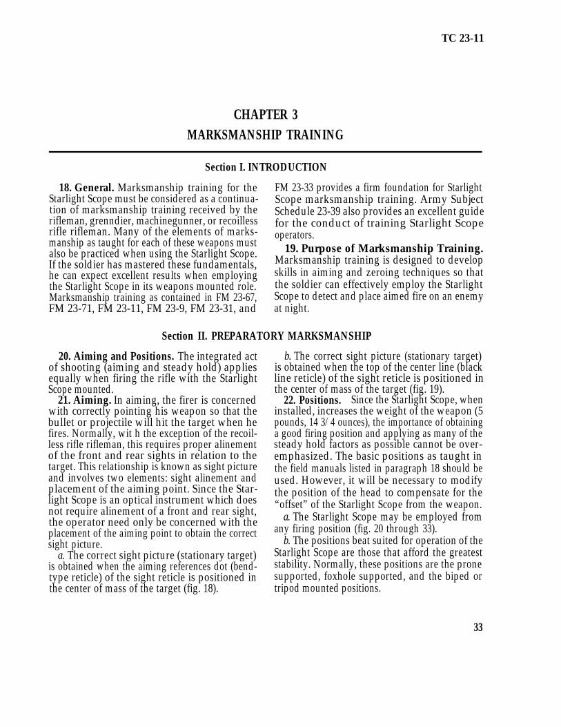
a. The correct sight picture (stationary target)is obtained when the aiming references dot (bend-type reticle) of the sight reticle is positioned inthe center of mass of the target (fig. 18).
b. The correct sight picture (stationary target)is obtained when the top of the center line (blackline reticle) of the sight reticle is positioned inthe center of mass of the target (fig. 19).
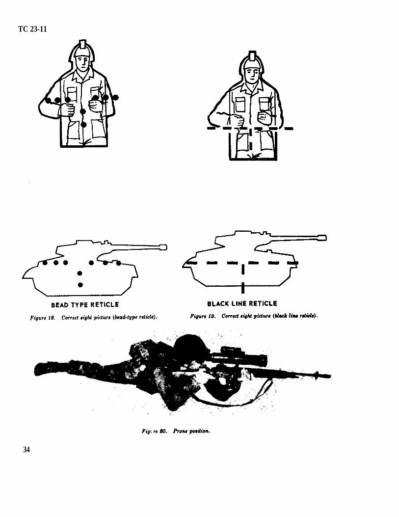
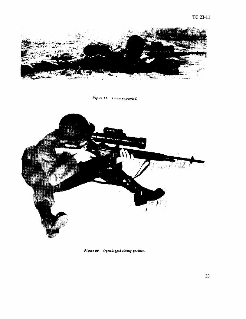
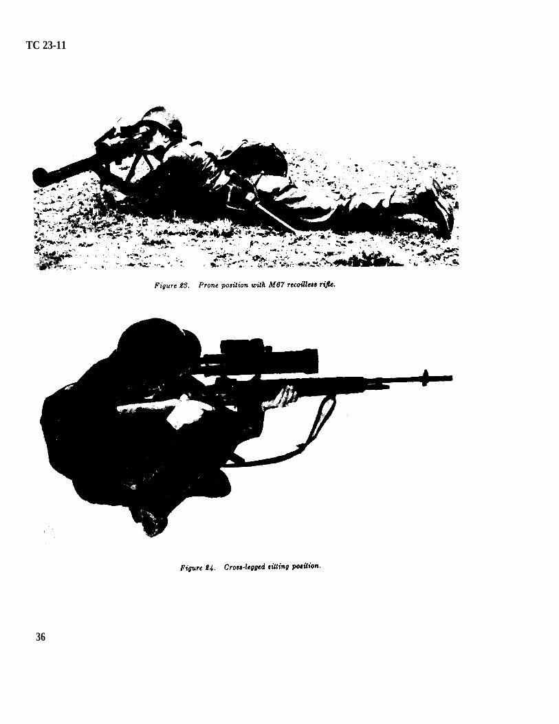
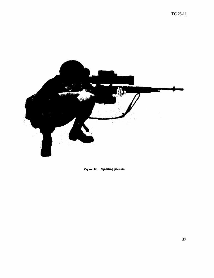
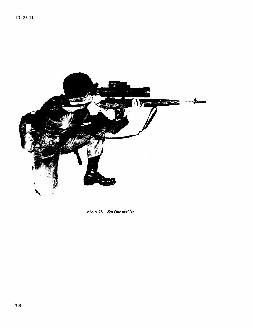
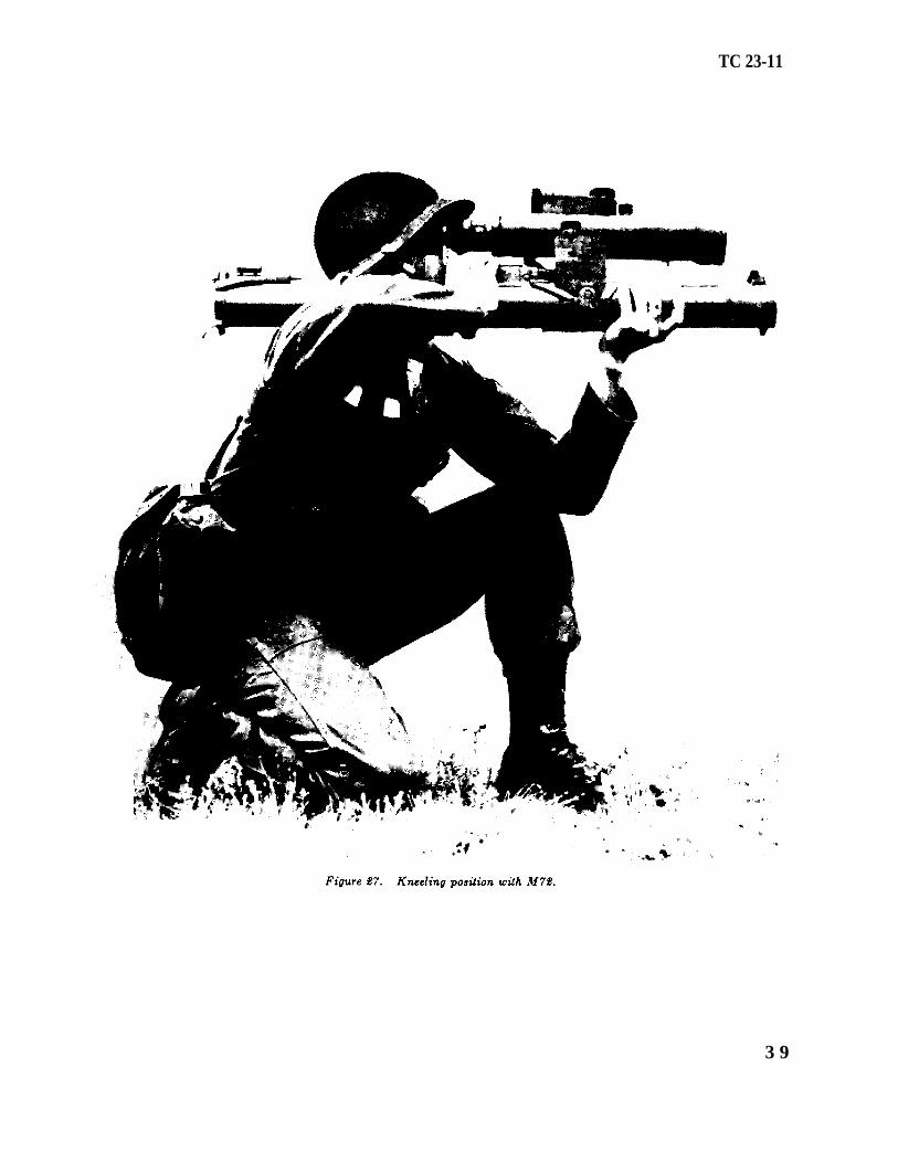
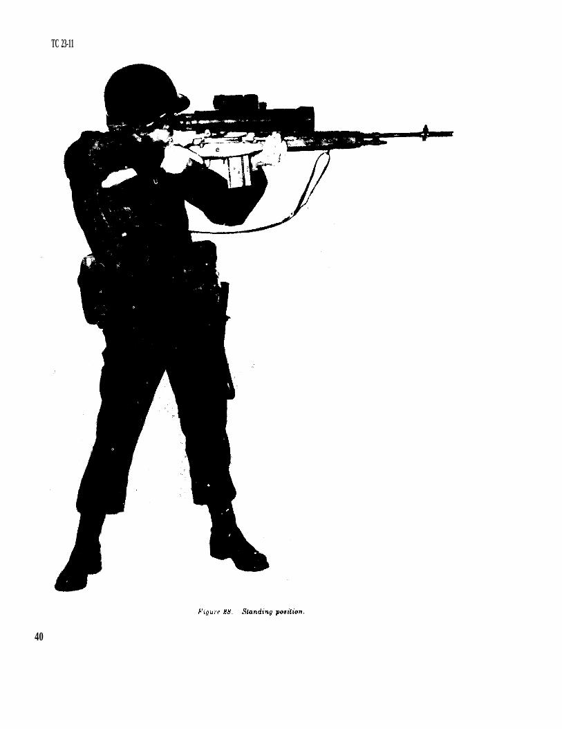
22. Positions. Since the Starlight Scope, wheninstalled, increases the weight of the weapon (5pounds, 14 3/4 ounces), the importance of obtaininga good firing position and applying as many of thesteady hold factors as possible cannot be over-emphasized. The basic positions as taught inthe field manuals listed in paragraph 18 should beused. However, it will be necessary to modifythe position of the head to compensate for the“offset” of the Starlight Scope from the weapon.
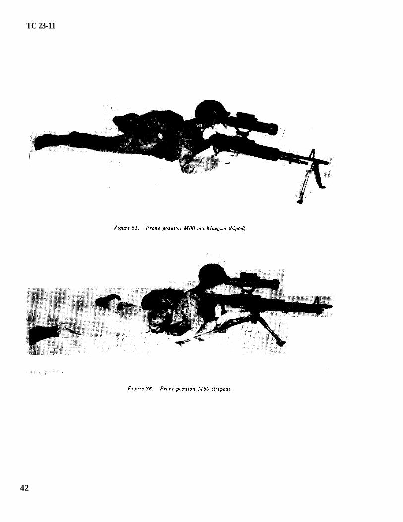
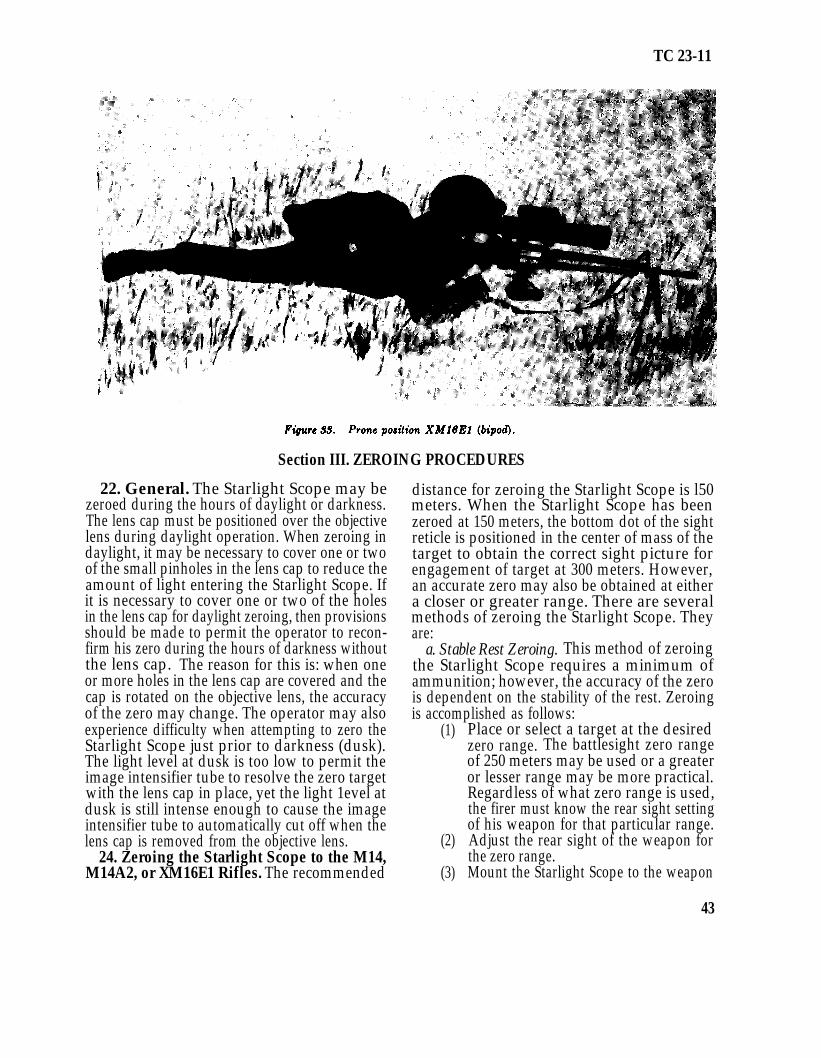
a. The Starlight Scope may be employed fromany firing position (fig. 20 through 33).
b. The positions beat suited for operation of theStarlight Scope are those that afford the greateststability. Normally, these positions are the pronesupported, foxhole supported, and the biped ortripod mounted positions.
33
TC 23-11
34
TC 23-11
35
TC 23-11
36
TC 23-11
37
TC 23-11
3 8
TC 23-11
3 9
TC 23-11
40

TC 23-11
41
TC 23-11
42
TC 23-11
Section III. ZEROING PROCEDURES
22. General. The Starlight Scope may bezeroed during the hours of daylight or darkness.The lens cap must be positioned over the objectivelens during daylight operation. When zeroing indaylight, it may be necessary to cover one or twoof the small pinholes in the lens cap to reduce theamount of light entering the Starlight Scope. Ifit is necessary to cover one or two of the holesin the lens cap for daylight zeroing, then provisionsshould be made to permit the operator to recon-firm his zero during the hours of darkness withoutthe lens cap. The reason for this is: when oneor more holes in the lens cap are covered and thecap is rotated on the objective lens, the accuracyof the zero may change. The operator may alsoexperience difficulty when attempting to zero theStarlight Scope just prior to darkness (dusk).The light level at dusk is too low to permit theimage intensifier tube to resolve the zero targetwith the lens cap in place, yet the light 1evel atdusk is still intense enough to cause the imageintensifier tube to automatically cut off when thelens cap is removed from the objective lens.
24. Zeroing the Starlight Scope to the M14,M14A2, or XM16E1 Rifles. The recommended
distance for zeroing the Starlight Scope is l50meters. When the Starlight Scope has beenzeroed at 150 meters, the bottom dot of the sightreticle is positioned in the center of mass of thetarget to obtain the correct sight picture forengagement of target at 300 meters. However,an accurate zero may also be obtained at eithera closer or greater range. There are severalmethods of zeroing the Starlight Scope. Theyare:
a. Stable Rest Zeroing. This method of zeroingthe Starlight Scope requires a minimum ofammunition; however, the accuracy of the zerois dependent on the stability of the rest. Zeroingis accomplished as follows:
(1)
(2)
(3)
Place or select a target at the desiredzero range. The battlesight zero rangeof 250 meters may be used or a greateror lesser range may be more practical.Regardless of what zero range is used,the firer must know the rear sight settingof his weapon for that particular range.Adjust the rear sight of the weapon forthe zero range.Mount the Starlight Scope to the weapon
43
TC 23-11
and place the combination onto a stablerest.Carry out operating instructions asoutlined in paragraph 9 e (l) through (4).Sight through the rear sight of theweapon (not Starlight Scope) and alineon the aiming point of the zero target.Without disturbing the lay of the weaponor Starlightl Scope combination, sightthrough the Starlight Scope and, bymanipulating the azimuth and elevationadjustment knobs, move the sight reticleuntil the aiming reference dot is alinedon the same point of aim as the sightsof the rifle.When the aiming reference dot and therifle sights are alined on the same pointof aim on the zero target, the StarlightScope and weapon are zeroed for thatspecific range. Situation permitting, theoperator should fire a few rounds to con-firm the zero. When making adjust-ments in elevation or deflection, adjust-ments are made in the direction of theerror.
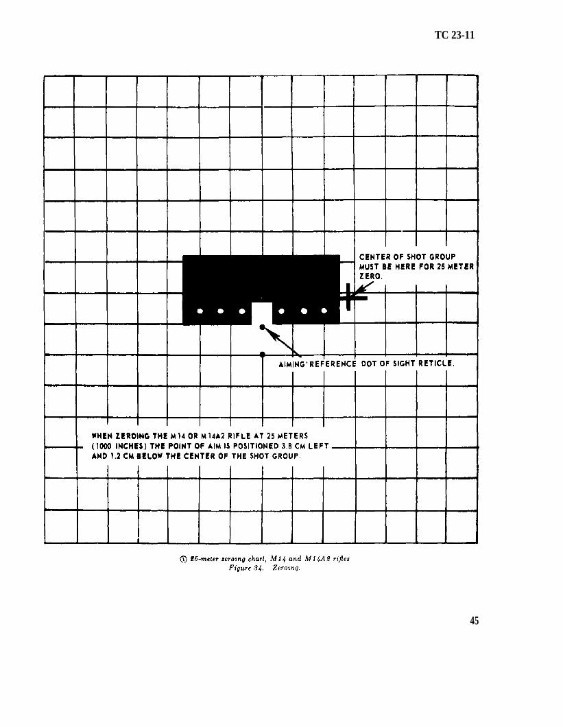
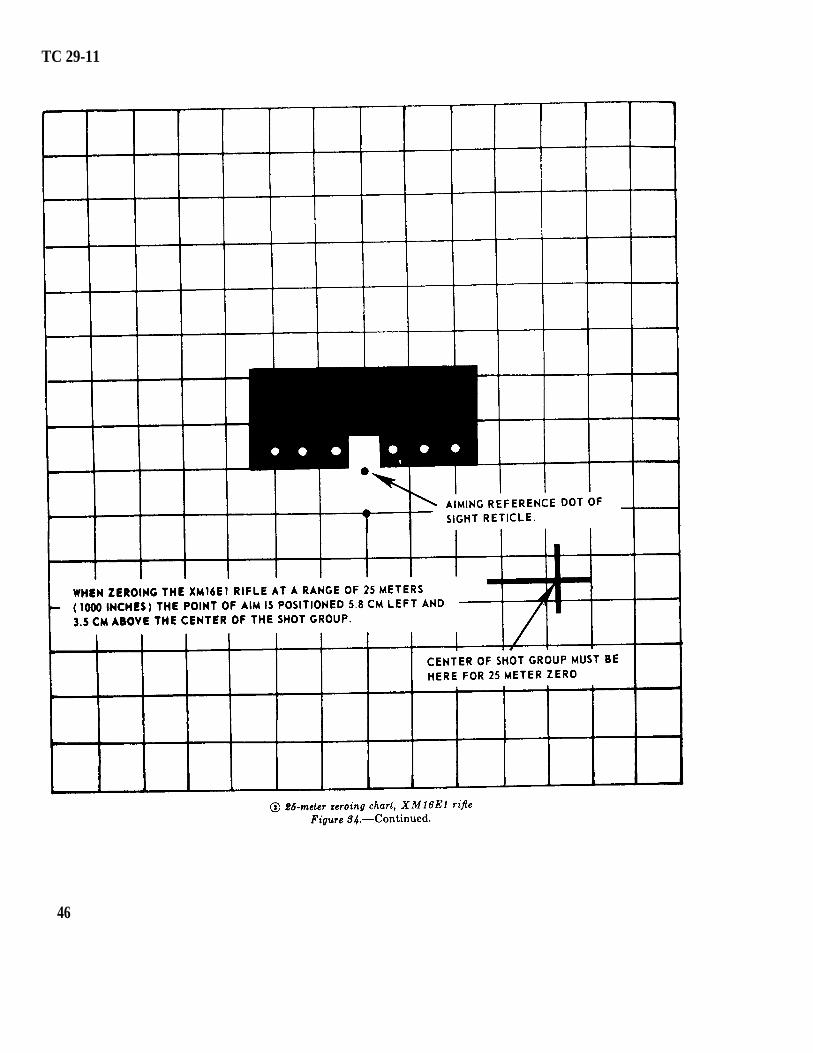
b. Battlesight Zeroing. In keeping with currentdoctrine of the United States Army, which pre-scribes a 250-meter battlesight zero and thesoldier’s need to be able to determine this zero at26 meters or 1,000 inches, a battlesight zero for theStarlight Scope may also be obtained at thisrange. The principles of zeroing, as described inFM 23-71, form a firm basis for teaching battle-sight zeroing of the Starlight Scope. The 25-meter zero target may be used; however, thecenter of the shot group has been moved tocompensate for the offset of the Starlight Scopewhen mounted. The Starlight Scope is zeroed at25 meters as follows:
Mount the Starlight Scope to the M14,M14A2, or XM16E1 rifle.The operator may select what position isto be used; however, the foxhole, pronesupported, or biped position is recom-mended for greater stability. The posi-tion selected must be located at theprescribed 25 meters or 1,000 inches fromthe target.Carry out operating instructions as de-scribed in paragraph 9e (1) through (4).
(4)
(4)in
(5)
(6)(5)
(7)
in
Sight through the Starlight Scope andposition the aiming reference dot of thesigh t reticle on the target as illustrated
figure 34. Fire a three-round shot group, insuring that theaiming reference dot is at the exact samepoint of aim on the target each time around is fired,Move to the target line and analyze thetarget to determine the location of thecenter of the shot group in relation topoint of aim. The correct relationshipbetween point of aim and the center ofthe shot group when zeroing with theM14 or M14A2 rifles is illustrated in figure 34. The correct relationship whenfiring the XM16E1 rifle is illustrated in
figure 34.Adjust the sight reticle by turning theelevation and/or azimuth adjustmentknobs until the aiming reference dot isat the prescribed location as illustrated
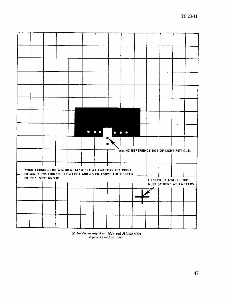
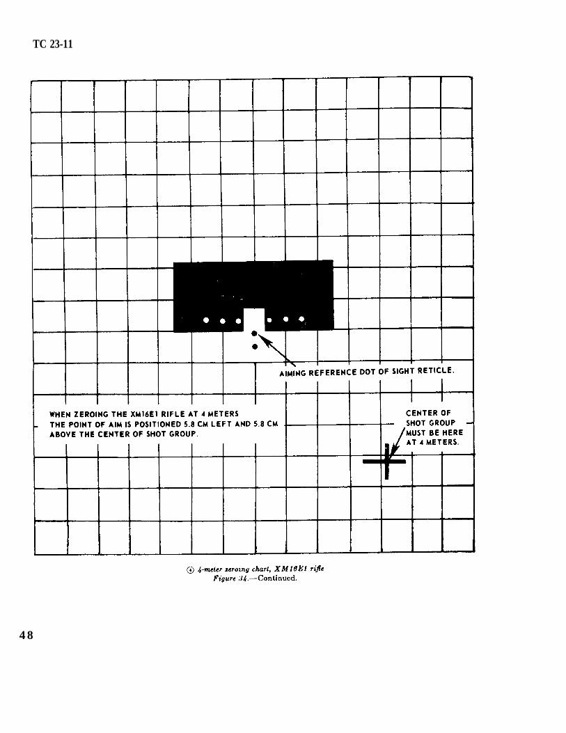
, figure 34. One click of theazimuth or elevation adjustment knobwill move the strike of the bullet 1.27centimeters or a little less than onesquare on the 25-meter target. Adjust-ments are made in the direction of theerror from where the center of the shotgroup must be. For example, if thecenter of the shot group is high and leftof where the shot group must be, thenthe operator adjusts for this error bymoving the sight reticle up and to theleft.Repent the procedures as outlined in (4)through (6) above until proper relation-ship between the point of aim and thecenter of the shot groups has beenobtained.A method of obtaining a battlesight zeroat 4 meters can also be accomplished byfollowing the procedures outlined in(4) through (7) above, and by changingthe relationship of the point of aim andthe strike of the round as illustrated in
figure 34, for the M14 and M14A2figure 34, for the XM16E1
rifle. When obtaining a 4-meter zerothe (operator must try for as accurate a
(6)
(7)
(1)
(2)(8)
rifles or(3)
44
TC 23-11
45
TC 29-11
46
TC 23-11
47
TC 23-11
4 8
(9)
zero as possible, for a very slight errorat 4 meters results in a major error at250 meters.
The advantage of the 4-meter zero, ascompared to a 25-meter zero, is that theoperator can see the strike of the roundon the target and can adjust the sightreticle without moving from the weapon,thus eliminating movement time betweenweapon and target and reducing thetime required for zeroing. When zeroingat 4 meters, each click of the azimuth orelevation adjustment knob moves thestrike of the round .2 centimeter.Due to the differences between firers,
weapons, and ammunition, and the diffi-culty in obtaining a precise zero at 4 or25 meters, zeroes obtained at theseranges should be confirmed by firing onthe actual range.
c. Field Expedient Zeroing. This method ofzeroing is similar to the method described inFM 23-71. This method may require the we ofan observer to assist in locating the strike of theround and giving the changes in elevation anddeflection necessary to bring it to the point ofaim. During daylight zeroing the observer shouldbe equipped with binoculars, and during thehours of darkness a Starlight Scope, to assist himin this procedure. This method of zeroing isconducted as follows:
(10)
(1)
(2)
(3)
The operator mounts the Starlight Scopeto his weapon and carries out operatinginstructions as described in paragraph9e (1) through (4).The operator and observer pick out atarget that provides a definite point ofaim and one that will aid in observingthe strike of the bullet. This can beu hillside, a brick house, or any dry ormetal surface.Center the aiming reference dot in theStarlight Scope’s field of view. Thismay be accomplished by sighting throughthe scope and estimating if the aimingreference dot is centered. It may alsobe accomplished by counting the totalnumber of clicks the aiming reference dotcan be moved in both elevation and
(4)
(5)
(6)
TC 23-11
azimuth and then positioning the aimingreference dot at midpoint.Place the aiming reference dot at thepoint of aim and fire one round. Theobserver notes the strike of the bulletand gives the elevation and deflectionchange necessary to bring it to the pointof aim. He dose this by estimatingthe distance between the strike of thebullet and the aiming point. He con-verts these distances to clicks by dividingthe error (in inches) by the number ofinches one click will move the strike ofthe bullet at that range. For example,an operator fires one round at his zerotarget at a range of 150 meters. Theobserver estimates the strike of theround to be 2 feet above and 3 feet rightof the aiming point. His correctionswould be: up 8 clicks (24 inches at thatrange) and right 12 clicks (36 inchesat that range). The operator makesthese adjustments to the reticle andfires a confirming round.He continues the foregoing proceduresuntil the point of aim and strike of thebullet coincide.Because the operator is making a sightchange on the basis of one shot, it isextremely important that the shot bewell-aimed and correctly fired. Heshould also use his most stable firingposition.
d. Holdoff. To engage targets at other thanthe zero range, the operator must apply holdoffto compensate for the rise and fall in the trajectoryof the round. To engage targets at ranges lessthan the zero range, the point of aim will bebelow the center of mass.
25. Zeroing Starlight Scope to M60 Machine-gun. The procedures used to zero the StarlightScope to the M60 machinegun are basically thesame as those for the rifle. Zeroing can beaccomplished using the basic (l0-meter) method,known distance target method, and the fieldexpedient method. Regardless of which pro-cedure is used, the basic marksmanship techniquesas described in FM 23-67 will apply.
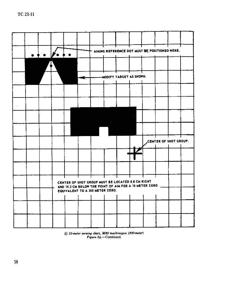
a. Basic (10-Meter) Zero. This method ofzeroing is equivalent to a 300-meter zero and
49
TC 23-11
50
target
may be used when engaging targets at ranges of500 meters or less. The standard 25-meter
fig. 34), modified as shown, is used inlieu of the standard machinegun targets; how-ever, the target is still positioned 10 meters fromthe muzzle of the weapon. Zeroing is accom-plished as follows:
(1)
(2)
(3)
(4)
in
Mount the Starlight Scope to the M60machinegun and carry out operatinginstructions as described in paragraph9 e (1) through (4).Sight through the Starlight Scope andposition the aiming reference dot of thesight reticle on the target as illustrated
figure 34. Fire three rounds(single shot) to establish a shot group.The operator must insure the aimingreference dot is positioned at the exactsame point of aim each time a round isfired.The operator checks his target to deter-mine the location of the center of theshot group in relation to where hisrounds must strike the target for anaccurate zero. The correct relationshipbetween the point of aim and the centerof the shot group is illustrated infigure 34. This relationship must beobtained to have an accurate lo-meterzero. If the center of the shot groupis other than shown inthe operator must adjust the elevationand/or azimuth adjustment knob of theStarlight Scope to bring the point ofaim and the center of the shot group intoproper alinement.
After making adjustments for elevation
figure 34, then
figure 34.
and/or deflection, the operator re-layson his target and fires a confirming round.If the round dose not strike the targetat the desired location, he treats thishit as the center of a three-round shotgroup, makes further adjustments asnecessary, and fires smother round. Hecontinues this procedure until the pointof aim and the strike of the round arein the proper relationship.
b. Known Distance Target Method. When usingthis method to zero the M60 machinegun, the
TC 23-11
tripod should be used. If the tripod is not avail-able, a stable rest must be provided to affordmaximum stability for the weapon and StarlightScope combination. The Starlight Scope is zeroedto the M60 machinegun as follows:
(1)(2)
(3)
(4)
(5)
(6)
Zero the M60 machinegun.Mount the Starlight Scope to the M60machinegun and carry out operatinginstructions as described in paragraph9e (1) through (4).Select a target at a known distance.Place this range setting on the rear sightand aline the sight on the distant aimingpoint.Without disturbing the lay of the weapon,sight through the Starlight Scope anddine the aiming reference dot on the samepoint of aim.Recheck to insure the lay of the weaponhas not been disturbed and that botheights are alined on the same point ofaim on the target.If the situation permits, fire a few roundsto confirm the zero.
c. Field Expedient Zeroing. The procedures asprescribed in paragraph 24c may be used to zerothe Starlight Scope to the M60 machinegun. Theoperator may fire a short burst in lieu of the oneround as described.
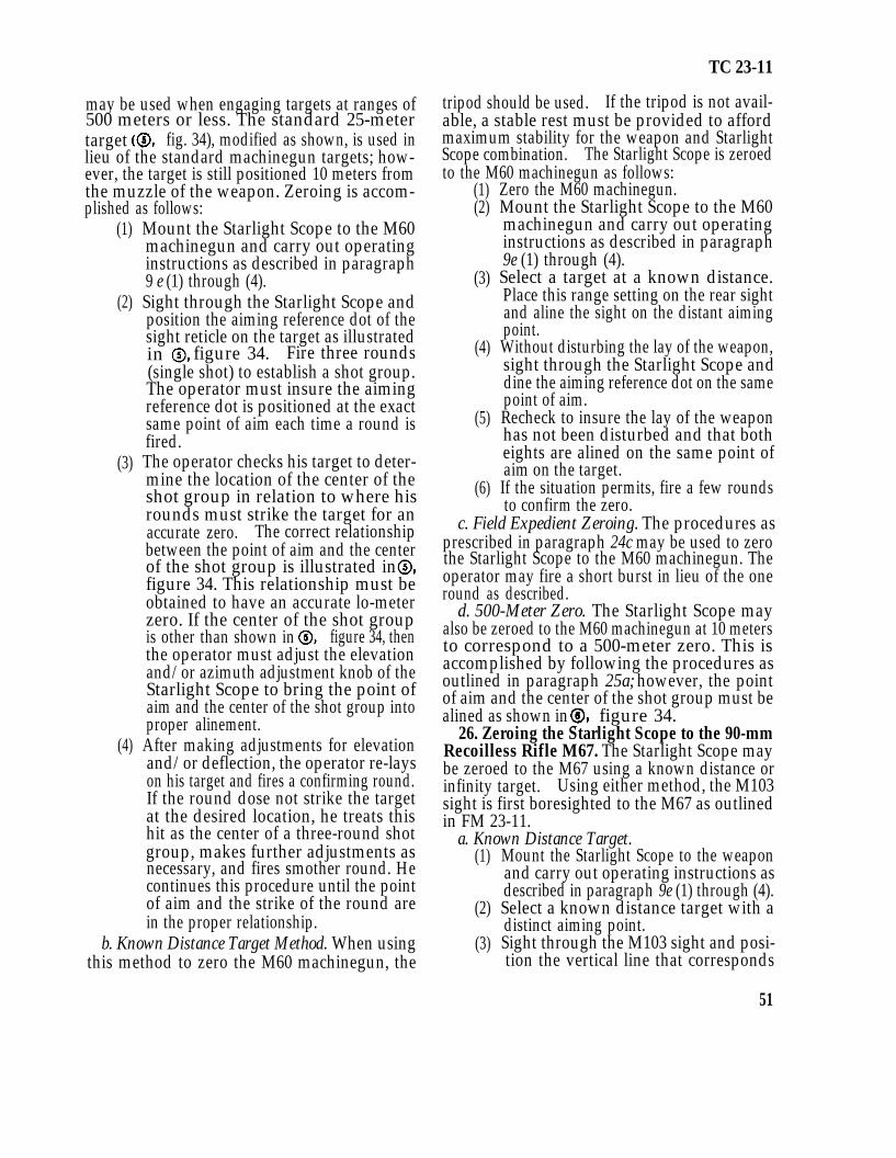
d. 500-Meter Zero. The Starlight Scope mayalso be zeroed to the M60 machinegun at 10 metersto correspond to a 500-meter zero. This isaccomplished by following the procedures asoutlined in paragraph 25a; however, the pointof aim and the center of the shot group must bealined as shown in
26. Zeroing the Starlight Scope to the 90-mmRecoilless Rifle M67. The Starlight Scope maybe zeroed to the M67 using a known distance orinfinity target. Using either method, the M103sight is first boresighted to the M67 as outlinedin FM 23-11.
a. Known Distance Target.(1)
(2)
(3)
Mount the Starlight Scope to the weaponand carry out operating instructions asdescribed in paragraph 9e (1) through (4).Select a known distance target with adistinct aiming point.Sight through the M103 sight and posi-tion the vertical line that corresponds
51
TC 23-11
52
(4)
(5)
(6)
with the range to the target on theaiming point.Without disturbing the lay of the weapon,set the elevation indexing ring (fig. 14)of the weapons adapter bracket at thesame range setting as the M103 sight.Each clockwise click of the elevationknob (fig. 14) will increase the range by50 meters.Sight through the Starlight Scope andaline the aiming reference dot of themight reticle on the same point of aim.Recheck to insure both sights are alinedon the same point of aim. If the situa-tion permits, the operator should fire toconfirm the accuracy of the zero.
b. Infinity Target. Infinity zeroing with theM67 and the Starlight Scope is accomplished byusing the same procedure as described in a abovewith the exception that the boresight cross of theM103 sight is alined on the infinity target andthe elevation indexing ring is positioned on zero.
27. Zeroing the Starlight Scope to the M72.To zero the Starlight Scope to the M72 LAW,the following procedures should be used:
TC 26-11
a. Select a known distance target at a range of200 meters or less.
b. Extend the M72 and mount the Starlightscope.
c. Carry out operating instructions as describedin paragraph 9 e (1) through (4).
d. Place the M72 and Starlight Scope in astable rest position or assume a position that willprovide maximum stability.
e. Look through the sight of the M72 and alinethe corresponding range line of the eight with aspecific point on the target.
f. Set the elevation indexing ring of the weaponsadapter bracket (fig. 13) at the same range matting.Each clockwise click of the elevation knob (fig.13) will increase the range by 25 meters.
g. Without disturbing the lay of the weapon,sight through the Starlight Scope and, by manipu-lating the elevation and azimuth adjustmentknobs, aline the aiming reference dot of the eightreticle on the same point of aim.
h. Recheck both sights to insure that they arealined on the same point of aim.
53