Embed Size (px)
Citation preview

Chapter 27: Irradiation Growth and Creep 27.1. Introduction.............................................................................................................. 1 27.2 Irradiation Growth ................................................................................................... 3
27.2.1. Irradiation Growth in Metallic Uranium ....................................................... 4 27.2.2. Irradiation Growth in Zirconium alloys......................................................... 6
Quantitative Model for Irradiation Growth................................................................ 8 27.3 Irradiation Creep .................................................................................................... 11
27.3.1.Thermal Creep Mechanisms ........................................................................... 11 27.3.2. Irradiation Creep Mechanisms...................................................................... 12
Stress Induced Preferential Absorption Creep ......................................................... 12 Swelling-Driven Irradiation Creep Model.................................................................... 19
27.4 Void Swelling ........................................................................................................... 22 27.3.1. Mechanism of void swelling ........................................................................... 23
Void Nucleation ........................................................................................................ 24 Void Growth.............................................................................................................. 24
Problems .......................................................................................................................... 25 References ........................................................................................................................ 26
Light Water Reactor Materials, Draft 2006 © Donald Olander and Arthur Motta 12/10/2009 1

27.1. Introduction It is a common observation that during in-reactor service fuel assemblies and other in-core structural components change dimensions due to permanent plastic deformation. These dimensional changes are caused by the processes of irradiation creep, growth and void swelling. Void swelling is discussed in Chapter 19, and creep and growth are reviewed in this chapter. Creep and growth are important issues for fuel cladding behavior. Although the associated dimensional changes are well-known and allowed for in fuel rod design to burnups of 30-40 GWd/t, the operation of fuel to high burnup can cause dimensional instability to become a limiting factor to fuel rod usage. In other types of reactors, these dimensional instabilities can be life-limiting. Shape changes that occur in CANDU reactors pressure tubes, cause tube sagging and may require re-tubing. As mentioned above, the irradiation-induced processes that lead to changes in material dimensions during reactor exposure are:
• Irradiation Growth • Irradiation Creep • Void Swelling
These three processes are caused by different microstructural mechanisms and have different characteristics, as illustrated in Figure 27.1 and tabulated in Table 27.1. Irradiation Growth refers to a change in shape of an unstressed anisotropic material, occurring only under irradiation, and caused by the interaction of point defects with microstructural sinks. Irradiation Creep refers to a slow deformation at constant volume, in a material that is subjected to a stress below the yield stress; the role of irradiation is to accelerate creep mechanisms that occur outside irradiation. Void Swelling refers to an isotropic volume increase in an unstressed material caused by the formation of voids inside the material resulting from the agglomeration of point defects and gas atoms. Table 27.1 Characteristics of dimensional changes of metals due to neutron irradiation Process Applied
Stress Crystal structure
Strain Cause
Growth None Anisotropic (hcp, bct, etc.)
Anisotropic; constant volume
Point defect anisotropic absorption at sinks
Creep Anisotropic Any Anisotropic (in the direction of applied stress) constant volume
Stress-driven climb and glide of dislocations
Swelling Any or none Any; more prevalent in fcc metals
Isotropic volume increase
Clustering of point defects and gas atoms to form voids
Light Water Reactor Materials, Draft 2006 © Donald Olander and Arthur Motta 12/10/2009 1

Growth
Creep Swelling
ΔV=0
σ
σ σ =0 ΔV=0 ΔV>0 σ =0
Figure 27.1: Schematic showing the different types of dimensional instability under irradiation and their characteristics. Deformation of in-core components of LWRs is usually caused by a combination of growth and creep. An excellent description of creep-growth effects has been provided by Franklin and Adamson [1]. Creep and growth are influenced by many factors, related both to irradiation conditions (temperature, flux, fluence, and fluence gradients) and material microstructure (texture, state of cold-work, residual stresses, grain shape and size, etc). Components that are deformed by creep/growth and the observed effect include: 1. Fuel-rod axial elongation, due to: (a) growth – no stress; a fuel rod can grow several centimeters after a long irradiation (b) creep – pressure gradients in coolant (Arthur: can you explain this?) (c) creep – the cladding follows axial swelling of the pellets if the bond between the two is sufficiently tight 2. Cladding “creepdown”: slow decrease in cladding diameter due to irradiation creep that continues until the cladding grasps the fuel pellets. The driving force is the pressure difference across the cladding wall; the coolant pressure (15 MPa in PWRs) is much greater than the internal pressure in the rod. Internal pressure is usually 2 MPa at fabrication (300 K) and increases to ~ 4 MPa during operation (plenum gas at ~600 K). Fission-gas and helium release increases this value. Creepdown is not a problem in BWR fuel because the external pressure is lower than in a PWR (7 MPa vs 15 MPa) and because the cladding is thicker in BWR fuel elements than in PWR fuel elements. 3. Grid-spring creep relaxation: grids are periodically placed ~ 70 cm apart along the length of the assembly. They are intended to hold the fuel rods tight enough to minimize rod vibration but not so tight that the cladding is deformed. During operation, the grid force on the rods decreases by the classic process of creep relaxation. If not accounted for by design, loose rods rub against the grid structure leading to failure of the cladding by fretting.
Light Water Reactor Materials, Draft 2006 © Donald Olander and Arthur Motta 12/10/2009 1

4. BWR channel bow and PWR assembly lean The terms “bow” and “lean” are basically the same: they are measures of the deflection of the component from its originally-vertical position. The difference between the two is the location of the measurement: bow is in the midplane and lean is at the top. (Arthur: Fig. 12 of Ref. 1 seems to have the location of the bow wrong). These deformations are caused by differences in the neutron flux (and perhaps the temperature) on sides of the component (see “fluence gradients” above). The side of the component closest to the center experiences higher flux and consequently greater growth than the other side. As a result, the channel or assembly pattern in the core tends to open up like a flower. In BWRs, the component that bows is the channel in which the fuel assembly is housed; in PWRs, which have no channel, it is the differential growth/creep between the near-center and the far-center rods in the assembly that is responsible for the distortion. Creep relaxation In the remainder of this chapter, the microscopic basis of growth and creep is explained. Each atom in an in-core metal or alloy is displaced on average ten times during three reactor years. The metal is highly supersaturated with both types of point defects. Large defect fluxes to sinks result, such that even minute imbalances in the rates of interstitial and vacancy annihilation at different sinks cause a net accumulation of one or the other defect. In this chapter we use rate theory to show how these microscopic processes lead to macroscopic changes in the dimensions of metals. 27.2 Irradiation Growth Growth means an increase in one direction of a metal structure and decreases in one or both of the other two directions. The volume remains unchanged and the shape change occurs without an applied stress. Growth occurs by preferential interaction of irradiation-produced point defects with anisotropic sinks in the metal. In addition, crystal anisotropy must be macroscopically manifest in the as-fabricated component. That is, if the grains of the metal (which are small single crystals) are randomly oriented, growth does not occur. Unfortunately, the method of fabricating Zircaloy components invariably results in grains with the basal poles of the hcp crystal structure lined up in a preferred direction (Chap.17), thereby producing the necessary condition for growth. Irradiation growth also occurs in other anisotropic materials such as orthorhombic uranium, graphite and hexagonal close packed structures of zinc and cadmium, but not in cubic materials such as iron. Thus, two kinds of anisotropies are needed for growth to occur: microscopic anisotropy (of the crystal structure) and macroscopic anisotropy (of grain orientation). Not only do dimensions and shape change under irradiation for these metals, but some physical properties differ according to crystal axes. For example, in U and Zr, the axes along which expansion and contraction occur during irradiation correspond to the axes of minimum and maximum thermal expansion, respectively.
Light Water Reactor Materials, Draft 2006 © Donald Olander and Arthur Motta 12/10/2009 1

27.2.1. Irradiation Growth in Metallic Uranium In the early days of development of nuclear power, metallic uranium was considered as a candidate for nuclear fuel [2]. Metallic uranium has several advantages compared to the now- standard uranium dioxide, most notably its high fissile atom density and high thermal conductivity; the latter permits operation at a lower fuel temperature than UO2 fuel. However, neutron irradiation of metallic uranium causes a pronounced change of shape, with elongation in one direction and shrinkage another. Figure 27.2 shows a single crystal of metallic uranium before and after neutron irradiation to a burnup of 1 GWd/t . The length has increased considerably in the axial direction, (parallel to the [010] direction in the orthorhombic crystal) and its initially circular cross section has become elliptical, with the minor axis of the ellipse in the [100] direction in the crystal. Thus the crystal grows in the [010] direction, shrinks in the [100] direction, and remains constant in the [001] direction. Since growth strains can be substantial (on the order of several hundred percent), metallic uranium was abandoned as a candidate fuel for power reactors
Fig. 27.2 Cylindrical single crystal of alpha-uranium before and after irradiation in a reactor (0.1% atom burnup) [from reference [2], as reported in [1]] Irradiation growth was initially measured empirically by the growth coefficient g, defined by the formula:
010 010
100 100
( ) exp( )
( ) exp( )
o
o
g
g
β β
β β
=
= − (27.1)
Light Water Reactor Materials, Draft 2006 © Donald Olander and Arthur Motta 12/10/2009 1

where β is the burnup, is the initial length along direction hkl, from which
(
ohkl
hklhkl o
hkl
ε Δ= )
010
100
( ) exp( ) 1( ) [1 exp( )]
gg
ε β βε β β
= −= − − −
(27.2)
Because irradiation growth occurs at constant volume, 100 010 001 0ε ε ε+ + = (27.3) and if gβ <<1 then
100 010
001 0ε εε
= −=
(27.4)
Buckley proposed a qualitative model for irradiation growth in uranium [3, 4], based on the preferential condensation of point defects in particular crystallographic planes, as shown in Figure 27.3. Thus, as a direct result of the displacement process, and without any need for point-defect diffusion, the point defects form clusters, with the vacancies condensing on the (100) planes and the interstitials on the (010) planes.
(110 vacancy loop (010) interstitial loop single interstitial single vacancy
Fig. 27.3: Scheme proposed by Buckley to explain irradiation growth in metallic uranium [3]. The anisotropic collapse of vacancy defect clusters on [110] planes coupled to the formation of interstitial clusters on [010] planes, occurring within the displacement cascade lead to a macroscopic strain.
Light Water Reactor Materials, Draft 2006 © Donald Olander and Arthur Motta 12/10/2009 1

A curious feature of uranium is the increase of the growth coefficient with decreasing temperature. Although Buckley’s model does not explicitly explain the temperature dependence of the growth coefficient, one can imagine that the low-temperature athermal process described above comes into competition with randomizing thermal rearrangements at higher temperatures, thus slowing the growth rate.
Fig. 27.4: The growth coefficient of uranium metal as defined in equation 27.1 [4]. 27.2.2. Irradiation Growth in Zirconium alloys. Of greater interest to the nuclear industry is the irradiation growth of Zr alloys, which we review in the next section. We also use this material to introduce a quantitative model that illustrated the general principles governing irradiation growth Figure 27.5 shows the irradiation growth exhibited by Zr-5% and 7% Pu alloys, when irradiated at 500 C to atom burnups from 0.8 to 1.8% [5]. The plutonium was inserted to create a high displacement rate, and to give a high total dose to the material. The length change is remarkable (the strain is on the order of 400%, with very small density variation). Although the total displacements in this case are several orders of magnitude higher than fuel cladding should normally be subjected to in-service, this experiment illustrates dramatically the process of irradiation growth.
Light Water Reactor Materials, Draft 2006 © Donald Olander and Arthur Motta 12/10/2009 1

Figure 27.5: Appearance of Zr-Pu samples before and after neutron irradiation, showing extensive irradiation growth. (a) Non-irradiated sample, (b) Zr-5%Pu, post-irradiation and (c) Zr-7%Pu, post-irradiation [5]. For Zr single crystals, irradiation growth consists of an expansion along the <a> (prism) directions, with a corresponding contraction along the c-axis, as shown in figure 27.4a. As shown in Fig.27.5, in zirconium alloys, is negative, while 0001ε 0110ε is positive The conservation of volume equation for a Zr single crystal is written: 0001 1010 12 10 0ε ε ε+ + = (27.5) and thus the absolute value of is twice that of the perpendicular strains. 0001ε In polycrystalline materials the material texture is what translates the change of shape in the single crystals into a macroscopic strain. For a polycrystalline sample the growth strain in macroscopic direction x, εx is related to the single crystal strain by:
Light Water Reactor Materials, Draft 2006 © Donald Olander and Arthur Motta 12/10/2009 1

x (1 3 )g xFε ε= − (27.6) where Fx is the resolved fraction of basal poles aligned with macroscopic direction x and
εg (=-20001ε ) is the growth strain of the single crystal. Fx is the Kearns texture factor,
defined in Chapter 17. Thus, a single crystal with one of the prism poles aligned with the macroscopic direction x, (Fx=0) would exhibit the growth strain εg, and a single crystal aligned with the basal poles in direction x (Fx=1) would show a negative growth strain of -2 εg. A randomly oriented polycrystal (Fx=1/3) would show a growth strain of zero. That is, not only is it necessary for the material to be anisotropic in its crystal structure, but such anisotropy must be translated into a texture in order for there to be a non-zero growth strain. As noted in chapter 17 the fabrication process of Zr alloy components induces a texture, in which, prism poles are preferentially aligned perpendicular to the axial (longitudinal) direction and basal poles are oriented at 30-40 degrees from the radial (normal) direction. This means that irradiation growth increases the axial length and reduces the thickness of the cladding tube. These changes can cause failure by bowing in restricted rods. Quantitative Model for Irradiation Growth The mechanism of irradiation growth in Zr alloys is the partitioning of point defects to different microstructure sinks that align themselves preferentially with particular crystallographic directions. We have shown in Chapter 17 that the neutron-irradiated microstructure of Zry consists of a mixture of both vacancy and interstitial <a> loops. These loops grow in from the onset of irradiation, and saturate (in size and number density) at a fluence of ~ 1x1025 n/m2+. After an “incubation” fluence of about 3x1025 n/m2, vacancy loops begin to form on the basal planes (<c>-component loops). These do not appear to saturate with fluence. Fig. 27.5 shows these two types of dislocation loops and Table 27.2 summarizes their characteristics#. Although the <a> loop is shown consisting of interstitials, <a> vacancy loops also form. The interstitial variety seems to dominate, however. The <c> loops are pure vacancy. The growth rate in the <a> directions is proportional to the net fluxes of interstitials and vacancies to the <a>interstitial loops and <a> vacancy loops. Per unit volume of metal, the net absorption rate of interstitials is: (27.7) ( ) (IL a IL a VL
I I a IL v a VL I I v a IL a VL v vJ z z D C z Dρ ρ ρ ρ< > < >< > < > < > < >= + − + ) C
where <a>IL = <a> interstitial loops on prism planes <a>VL = <a> vacancy loops on prism planes
+ In a light-water reactor, A fluence of 1x1025 n/m2 (En > 1 MeV) is roughly equivalent to about 2 dpa in zirconium # Dislocation loops or network dislocations which are not purely <a> or <c> are designated by <a+c>.
Light Water Reactor Materials, Draft 2006 © Donald Olander and Arthur Motta 12/10/2009 1

Neglecting <c> loops and all network dislocations, the point defect balances are: (27.8) ( )V a IL a VL gb Vk Z k D Cρ ρ< > < >⎡= + +⎣ V⎤⎦
) I
where k is the dpa rate and kgb is the grain-boundary sink strength. (27.9) ( a IL a VL
I a IL I a VL gb Ik z z k D Cρ ρ< > < >< > < >= + +
Eliminating DVCV and DICI from (27.7) using (27.8) and (27.9) gives:
( ) ( )
( )
aIL aVLI V gb a IL I V gb a VL
g aIL aVLI a IL I a VL gb V a IL a VL gb
z z k z z kk
z z k zρ ρ
ερ ρ ρ ρ
< > < >
< > < > < > < >
− + −=
⎡ ⎤ k⎡ ⎤+ + + +⎣ ⎦⎣ ⎦ (27.10)
If and all bias factors in the denominator are approximated by unity, a VL
Iz< > ≅ Vz (27.10)reduces to:
2 (( )
gb a IL aIL )g I V
a IL a VL gb
kk
kz z
ρε
ρ ρ< >
< > < >
=⎡ ⎤+ +⎣ ⎦
− (27.11)
The components of this “three-factor” formula are: - the displacement production rate k - The sink strength balance term - The loop bias factor difference If the interstitial and vacancy dislocation loop densities are approximately equal, then the growth strain will be proportional to the difference in dislocation bias factors for interstitials and vacancies (zI- zv). In this scenario, the vacancy and interstitial fluxes to the oriented sinks work mostly at odds with each other so that it is the only the difference between the two fluxes to the <a> dislocation loops that causes the observed strain. This model is approximately valid for recrystallized material at low fluences. In cold-worked material, the growth rates can be much higher. This is shown in Figure 27.6, which plots the growth strain versus temperature for both cold worked and recrystallized material [6].
Light Water Reactor Materials, Draft 2006 © Donald Olander and Arthur Motta 12/10/2009 1

Figure 27.6: Growth strain as a function of neutron fluence for Zircaloy, in the cold-worked and recrystallized states at reactor temperature and room temperature. This is because cold worked material exhibits a density of <c+a> network dislocations from the start of the irradiation. This means that interstitials are absorbed in <a> loops thus increasing the material dimensions in that direction, while vacancies are absorbed in <c> component loops or network (<c+a>) dislocations, which effectively means that both defect fluxes now contribute to the growth strain. i.e.:
loopsvacacv
.loopsaig JJ .int >+<>< +∝ε
Because of this the growth strain in cold worked material is normally higher than that in recrystallized material at the start of irradiation. However, at higher fluences (around 3-4 x 1025 n.m-2) other types of loops showing a component in the <c> direction start to appear, and the material starts to behave like cold worked material. This is what is termed accelerated or breakaway growth [6] [7]. According to Woo [8], the reason for the partitioning of the different defects to different sinks is the migration anisotropy of these defects in the zirconium crystal structure. They have proposed a model that states that since there is a diffusion anisotropy difference (DAD), the vacancies tend to migrate in the 0001 direction, while interstitials migrate in the perpendicular direction. Because of this, vacancies have a greater probability of interacting with dislocations whose habit planes are in the basal plane than in prism planes, causing the observed bias. MORE DETAILED EXPLANATION/DIAGRAM for DAD
Light Water Reactor Materials, Draft 2006 © Donald Olander and Arthur Motta 12/10/2009 1

27.3 Irradiation Creep As mentioned in chapter 11, the material behavior in a uniaxial tensile test is determined by its stress-strain curve. At stresses below the yield stress the material undergoes only elastic deformation and only above σY does permanent (or plastic) deformation occur. Strictly speaking, this is only true for tests in which the holding time at stress is short. When the material is held at stresses below σY for very long periods of time (weeks, months) plastic deformation can occur by creep. Thus, creep is defined as slow plastic deformation, under a stress smaller than σY. Irradiation creep can also have similar consequences as the other deformation mechanisms discussed in this chapter, i.e., failure or bowing due to excessive deformation, but it can also have a beneficial effect in relaxing stresses applied to the solid. 27.3.1.Thermal Creep Mechanisms Different creep regimes occur in various materials and several thermal creep mechanisms exist such as climb and glide, Coble creep, Nabarro-Herring creep, grain boundary sliding, etc. [13]. Deformation mechanism maps such as shown in figure 27.11a, are a good way of describing the temperature ranges and stresses at which we would expect to see different mechanisms active [14, 15].
Figure 27.7: Schematic deformation mechanism map under thermal conditions. The combination of homologous temperature and stress determines the dominant deformation mode; from [13]. GET BETTER EXAMPLE WITH NUMERICAL VALUES
Light Water Reactor Materials, Draft 2006 © Donald Olander and Arthur Motta 12/10/2009 1

In general, the climb-and-glide mechanism are restricted to high temperature (T/Tm> ??), where the intrinsic thermal defect concentration is high. Such conditions are mimicked at lower temperatures by the irradiation field. In general, the presence of irradiation enhances the rates of the thermal creep processes, for example by an enhanced diffusion coefficient present under irradiation. Irradiation also enables other mechanisms that can cause or enhance creep. 27.3.2. Irradiation Creep Mechanisms As mentioned in the previous sections, for all the irradiation processes in the sink dominated regime at steady state, in order to have a measurable strain it is necessary to have a partition of defects to sinks, otherwise the defect fluxes cancel. It is only necessary for one of the defects to have a preferential interaction with one of the sinks , as the annihilation of the opposite defect in the neutral sinks automatically increases to match the flux of defects to the preferential sinks. This partition can occur by several mechanisms. The principal class of mechanisms at the root of irradiation creep are the so-called climb-and-glide mechanisms. These mechanisms involve the preferential absorption of interstitials at dislocations, which causes the dislocations to climb and enables their glide, which causes the creep strain (see chapter 11 for thermal mechanisms). The preferential absorption of interstitials at dislocations can be caused by a variety of reasons. We present here two creep mechanisms that can occur under irradiation: stress induced preferential absorption (SIPA) creep and swelling-driven creep. Stress Induced Preferential Absorption Creep In the stress induced preferential absorption mechanism (SIPA) [16] stress applied to a solid with randomly oriented dislocations, causes preferential absorption of interstitials in those dislocations that are aligned with the applied stress, thus causing creep in that direction. This creep model can help explain the occurrence of irradiation in solids where no swelling induced creep is present, such as zirconium alloys. The distribution of edge dislocations is in general random. Figure 27.&& shows schematically the distribution of dislocations along the three equivalent orthogonal crystal directions. For a given applied stress direction, 1/3 of the dislocations will be aligned (i.e. glissile). These are shown schematically in Figure 27. in black while the non-aligned dislocations (2/3) are shown in gray. In the SIPA mechanism the interstitial absorption rate is greater for the aligned type of dislocations than for the non-aligned type. As a result, atoms are added preferentially to the half sheets of the aligned dislocations with the result that the material creeps in the direction of the applied stress. We present here a derivation of the SIPA mechanism. Box
Light Water Reactor Materials, Draft 2006 © Donald Olander and Arthur Motta 12/10/2009 1
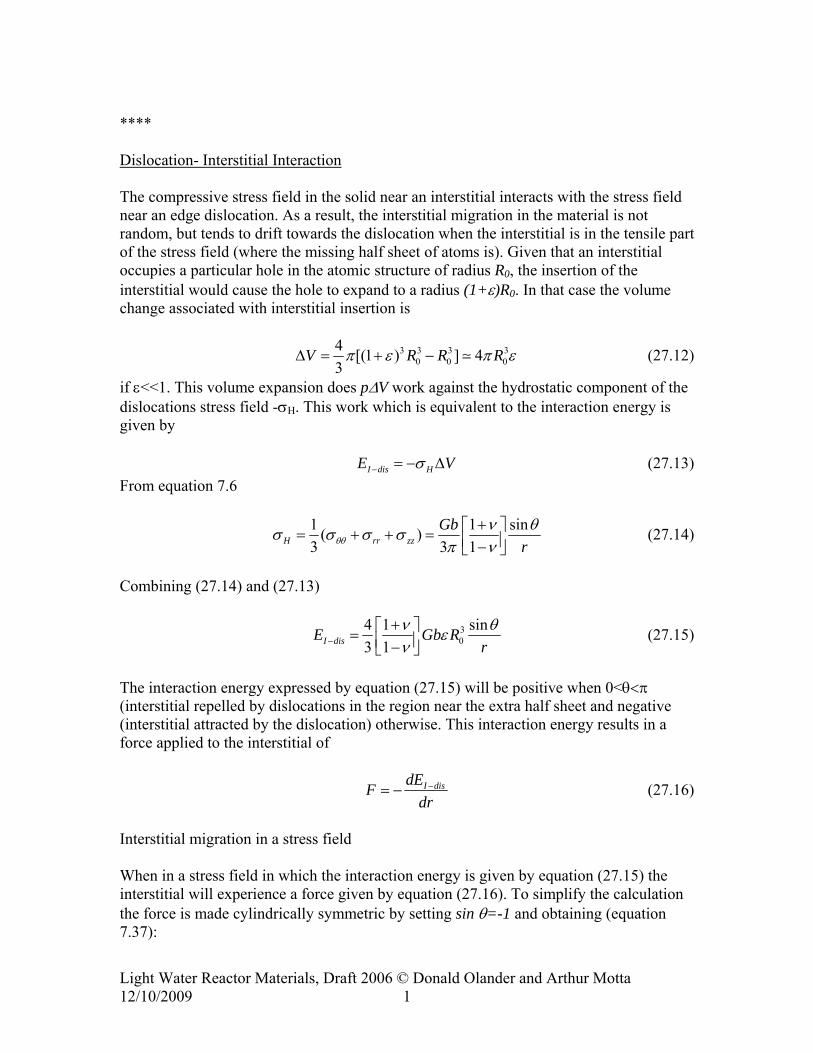
**** Dislocation- Interstitial Interaction The compressive stress field in the solid near an interstitial interacts with the stress field near an edge dislocation. As a result, the interstitial migration in the material is not random, but tends to drift towards the dislocation when the interstitial is in the tensile part of the stress field (where the missing half sheet of atoms is). Given that an interstitial occupies a particular hole in the atomic structure of radius R0, the insertion of the interstitial would cause the hole to expand to a radius (1+ε)R0. In that case the volume change associated with interstitial insertion is
3 3 3 30 0 0
4 [(1 ) ] 43
V R R Rπ εΔ = + − π ε
V
(27.12)
if ε<<1. This volume expansion does pΔV work against the hydrostatic component of the dislocations stress field -σH. This work which is equivalent to the interaction energy is given by I dis HE σ− = − Δ (27.13) From equation 7.6
1 ( )3 3 1H rr zz
Gbrθθ
1 sinν θσ σ σ σπ ν
+⎡ ⎤= + + = ⎢ ⎥−⎣ ⎦ (27.14)
Combining (27.14) and (27.13)
30
4 1 sin3 1I disE Gb R
rν θεν−
+⎡ ⎤= ⎢ ⎥−⎣ ⎦ (27.15)
The interaction energy expressed by equation (27.15) will be positive when 0<θ<π (interstitial repelled by dislocations in the region near the extra half sheet and negative (interstitial attracted by the dislocation) otherwise. This interaction energy results in a force applied to the interstitial of
I disdEFdr
−= − (27.16)
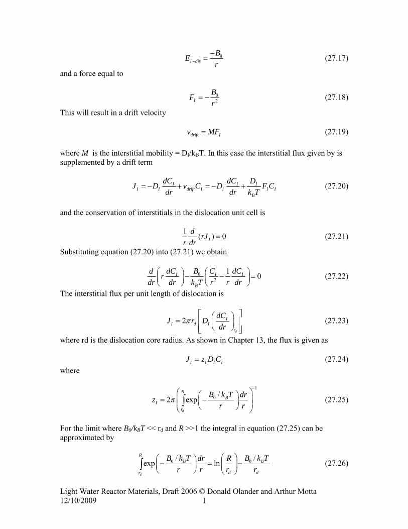
Interstitial migration in a stress field When in a stress field in which the interaction energy is given by equation (27.15) the interstitial will experience a force given by equation (27.16). To simplify the calculation the force is made cylindrically symmetric by setting sin θ=-1 and obtaining (equation 7.37):
Light Water Reactor Materials, Draft 2006 © Donald Olander and Arthur Motta 12/10/2009 1
0I dis
BEr−
−= (27.17)
and a force equal to
02I
BFr
= − (27.18)
This will result in a drift velocity drift Iv MF= (27.19) where M is the interstitial mobility = DI/kBT. In this case the interstitial flux given by is supplemented by a drift term
I II I drift I I I
B
dC dC DJ D v C D F Cdr dr k T
= − + = − + II (27.20)
and the conservation of interstitials in the dislocation unit cell is
1 ( ) 0Id rJ
r dr= (27.21)
Substituting equation (27.20) into (27.21) we obtain
02
1 0I I I
B
BdC C dCd rdr dr k T r r dr
⎛ ⎞ ⎛ ⎞− − =⎜ ⎟ ⎜ ⎟⎝ ⎠ ⎝ ⎠
(27.22)
The interstitial flux per unit length of dislocation is
2d
II d I
r
dCJ r Ddr
π⎡ ⎤⎛ ⎞= ⎢ ⎥⎜ ⎟
⎝ ⎠⎢ ⎥⎣ ⎦ (27.23)
where rd is the dislocation core radius. As shown in Chapter 13, the flux is given as I I IJ z D CI= (27.24) where
1
0 /2 expd
RB
Ir
B k T drzr r
π−
⎛ ⎛ ⎞= −⎜ ⎜ ⎟⎜ ⎟⎝ ⎠⎝ ⎠∫
⎞⎟ (27.25)
For the limit where B0/kBT << rd and R >>1 the integral in equation (27.25) can be approximated by
0 /exp lnd
RB
d dr
0 / BB k T B k Tdr Rr r r r
⎛ ⎞⎛ ⎞− ⎜ ⎟⎜ ⎟⎝ ⎠ ⎝ ⎠
∫ − (27.26)
Light Water Reactor Materials, Draft 2006 © Donald Olander and Arthur Motta 12/10/2009 1

and so the bias factor zI is
1
0 / 22 ln 1ln( / ) ln( / )
BI
d d d d
0 / d BB k T B r k TRzr r R r R r
ππ−
⎛ ⎞⎛ ⎞ ⎡ ⎤= − +⎜ ⎟⎜ ⎟ ⎢ ⎥⎜ ⎟⎝ ⎠ ⎣ ⎦⎝ ⎠
(27.27)
00
/1ln( / )
d BI v v
d
B r k Tz z z BR r
α⎡ ⎤
= + = +⎢ ⎥⎣ ⎦
(27.28)
In the absence of applied stress the interaction energy between interstitials and dislocations is given by
0I Adis
BEr−
−= (27.29)
where B0 is a constant and r is the distance between interstitial and dislocation. When a stress is applied the interaction energy for aligned and non-aligned dislocations are:
1 (I AdisBE alignedr− )−
= (27.30)
2 (I NAdisB )E non alignedr−
−= − (27.31)
The interaction coefficients B1 and B2 are given by 1 0 1B B c σ= + (27.32) 2 0 2B B c σ= + (27.33) where c1-c2=Δc > 0 is a material property. This creates a difference in the interstitial bias factors for the aligned and non-aligned dislocations that is given by 1 2 1 2( )I Iz z B B cα α σ− = − = Δ (27.34) This causes a net rate of interstitial atom by aligned dislocations equal to
1 11 1 (3 3
net d dI IJ Jρ ρ= − )vJ (27.35)
Light Water Reactor Materials, Draft 2006 © Donald Olander and Arthur Motta 12/10/2009 1

where is the interstitial flux to aligned dislocations, is the interstitial flux to non aligned dislocations and the vacancy flux to all dislocations, since no bias for vacancies exists (all these fluxes are in units of interstitials per second per unit dislocations line). Since each atom is associated with a volume equal to the cube of the lattice parameter, each interstitial absorbed into the half-sheet of the aligned dislocations increases the area of the half sheet by so that when 1/ are absorbed the dimension x (aligned with the load will increase by . Thus
1dIJ 2
dIJ
dvJ
3oa
2oa
oa
2oa
31
22
1 [interstitials per second per cm ]3
1 [interstitials to complete 1cm of half-plane]1/
[increase in x direction per half-plane]
SIPA netcreep I
o
o
x J xx
xa
a
ε ρ= =
(27.36)
or
31
13
SIPA netcreep I o
x J ax
ε ρ= = (27.37)
Since at steady-state the overall rate of absorption of interstitials and vacancies in
islocations is the same d
1 21 23 3
Using equation
d d d dv Iavg I IJ J J J= = + (27.38)
(27.38) to eliminate from equation dvJ (27.37) we obtain
31 2
2 ( )9
SIPA d dcreep I I oJ J aε ρ= − (27.39)
nd using equations (27.34) and (27.38) a
31 2
2 ( )9
SIPA dcreep Iavg I I oJ z z aε ρ= − (27.40)
dislocations are the only sinks and recombination is negligible, then If
(27.41) 3d
Iavg ok J aρ= and
Light Water Reactor Materials, Draft 2006 © Donald Olander and Arthur Motta 12/10/2009 1

2 ( ) 9creep
SIPA c k Cε = α σ σΔ = Φ (27.42)
where 2 ( )9 dC cα σ= Δ . Because the coefficient C is nearly independent of temperature
SIPA creep is approximately athermal. Equation (27.42) shows that creep is linearly proportional to the dose rate, in contrast with swelling driven creep which is proportional to the void swelling rate which is not proportional to dose rate. The derivation above omits the role of recombination and at low temperature this is not a good approximation, so that in reality the SIPA creep rate decreases strongly at low temperature.
Light Water Reactor Materials, Draft 2006 © Donald Olander and Arthur Motta 12/10/2009 1

σ
σ
Figure 27.((
Figure 27.11b: Diametral creep strain for recrystallized Zircaloy (under internal pressure, kept at 330 C), outside irradiation and under irradiation for two values of the neutron flux.
Light Water Reactor Materials, Draft 2006 © Donald Olander and Arthur Motta 12/10/2009 1

Vacancies in these models can be absorbed by several different sinks, including voids, grain boundaries, and dislocations. This explains why materials that do not undergo void swelling can still undergo creep: vacancies can go to sinks other than voids in these materials. Figure 27.11b shows the creep deformation of Zircaloy outside of irradiation and under irradiation. It is clear that increasing values of the displacement rate G cause ever-increasing creep strains. In the case of Zircaloy creep, anisotropies in the point defect migration or in defect absorption by different types of dislocations such as the diffusion anisotropy difference (DAD) or stress induced preferential absorption (SIPA) mechanisms mentioned above, have to be invoked to rationalize the creep strain. Also, in anisotropic materials, creep always has to be separated from growth in experimental situations. A convenient way to do this is to assume total growth creepε ε ε= + (27.43) and define creepε as the additional deformation that takes place when the external stress is different than zero. Swelling-Driven Irradiation Creep Model As illustrated in Figure 27.9, irradiation creep and void swelling can be coupled phenomena. In that case, we have swelling-driven irradiation creep. The purely thermal variant mechanism where vacancies rather than interstitials drive the climb step is discussed in Chapter 7. The model presented here for this type of mechanism is valid for steels, where void swelling occurs, but not for Zircaloy. In the case of steels, the creep rate originates in the excess flux of interstitials to dislocations. The creep strain can be written (27.44) vm
d bε ρ= d
where
density of mobile dislocations Burgers vector
v average dislocation velocity along slip planes
md
d
bρ =
==
Light Water Reactor Materials, Draft 2006 © Donald Olander and Arthur Motta 12/10/2009 1

obstacle
climb
l
h
glide
obstacle Figure 27.12: The climb and glide mechanism of irradiation creep. A dislocation that is stopped at an obstacle absorbs point defects that allow it to change its plane and thus avoid the obstacle. When enough climb has occurred, glide occurs very quickly. Dislocation climb is a process that is controlled by defect absorption on dislocations and is therefore limited by the migration rates of defects in the solid. Once the dislocations have climbed enough that they clear the obstacles, glide occurs relatively fast. Because of this we can write that the dislocation velocity is approximately equal to the climb velocity:
vdc
lt
= (27.45)
and the time to climb a barrier h is
C C
ht = v
(27.46)
where h is the barrier height, determined by the interaction of dislocation with the obstacle, as shown in Chapter 7. For example if the obstacle is an immobile dislocation then:
8 (1 ) xy
Gbhπ υ σ
=−
(27.47)
The climb velocity vc is calculated by computing the imbalance between the vacancy and interstitial defect fluxes to dislocations.
Light Water Reactor Materials, Draft 2006 © Donald Olander and Arthur Motta 12/10/2009 1

v dtcj v
j i
b Figure 27.13: The absorption of defects at dislocation causing dislocation climb. From conservation of mass, in time dt the defect fluxes and the dislocation climb are related by: ( ) vi v cj j dt b dt− Ω = (27.48) where Ω is the atomic volume and j ji v, =defect fluxes per unit length of dislocation line [defect.s-1.cm-1]
( - ) . ( - ) v = = i v i i i v v vc
j j z D C z D Cb b
Ω Ω (27.49)
The total fluxes are related to the flux per unit length by the equation
- dis disi v
i v i i i v vd
J Jvj j z D C
ρ−
− = = z D C (27.50)
A relationship can be found between void swelling and irradiation creep by imposing the condition (27.51) dis dis void void
i v v iJ J J J− = − 27.39 But
Light Water Reactor Materials, Draft 2006 © Donald Olander and Arthur Motta 12/10/2009 1

( ) 4 (d i i i v v v i i v vd V V z D C z D C RN D C D Cdt V V
ρ π⎛ ⎞Δ Δ⎛ ⎞ = = Ω − = Ω −⎜ ⎟⎜ ⎟
⎝ ⎠ ⎝ ⎠) (27.52)
So the climb velocity can be written in terms of the void swelling strain rate
1vcd
VV bρ
⎛ ⎞Δ Ω= ⎜ ⎟Ω ⎝ ⎠
(27.53)
This can now be substituted in the equation (27.44) for the creep strain, remembering that
vdlh
≅ vc (27.54)
And thus finally
8 (1 )1v xym m
irr d c dd b
l Vb lh V G
π ν σε ρ ρ
ρ−⎛ ⎞Δ
= = ⎜ ⎟⎝ ⎠
(27.55)
8 (1 )md
irr xyd b
l VG V
ρ π νε σρ
⎛ ⎞− Δ= ⎜ ⎟
⎝ ⎠ (27.56)
Thus, the in swelling-driven creep by a climb and glide mechanism, the creep rate is directly proportional to the swelling rate, as well as to the applied stress and the fraction of mobile dislocations. 27.4 Void Swelling The phenomenon of void swelling was discovered by Cawthorne and Fulton [9], who attributed it to the formation of cavities in solids during irradiation. The phenomenon can be observed with the naked eye in Figure 27.7a, which depicts the change in dimensions undergone by stainless steel after a high fluence irradiation.
(a) (b)
Light Water Reactor Materials, Draft 2006 © Donald Olander and Arthur Motta 12/10/2009 1

Figure 27.7 (a): Swelling observed after irradiation to 1.5 x 10²³ n.cm-2 (E >0.1 MeV) at 510 C in EBR-II (or equivalent to about 75 dpa) [10];. (b) TEM micrographs of voids formed in 316 stainless steel, during irradiation at various temperatures in FFTF (Fast Flux Test Facility) to a fluence of 1.4 x 10²³ n.cm-2 (W.J.S. Yang picture, from reference [11]). Since the number of transmutation He atoms formed during irradiation is considerably less than necessary to explain the observed strain, these cavities had to be mostly constituted of vacancies, and hence the name void swelling. Figure 27.7b shows transmission electron micrographs depicting the evolution of voids formed during neutron irradiation of stainless steel. It is clear from the pictures that voids increase with irradiation and the void growth does not saturate. Because void swelling was observed in stainless steel, which was to be used for fuel cladding in fast breeder reactors, there was considerable impetus, especially in the 1970s to perform research in this area. Also the swelling of uranium dioxide during reactor exposure, is of great technological interest, since it affects fission gas release (see chapter 20) and can cause pellet-cladding interaction. Such research has uncovered many of the basic mechanisms of void swelling. We review some of these in the following section. 27.3.1. Mechanism of void swelling The microscopic mechanism of void swelling is the formation of small cavities in the solid, perhaps with a little gas in them, which helps stabilize the void embryos. Most metals undergo void swelling under neutron irradiation, in the range of 0.3 to 0.55 of the melting temperature. One of the pre-conditions of swelling is the existence of some gas in the material.
Light Water Reactor Materials, Draft 2006 © Donald Olander and Arthur Motta 12/10/2009 1
Voids form by the condensation of vacancies into clusters, which can then grow by net vacancy absorption or by coalescence with other voids. We can divide this process into one of void nucleation and void growth. Void Nucleation In chapter 10 we described the nucleation of a second phase from a solid solution. We showed that nucleation of a second phase occurs when a nucleus of a critical size is formed above which it is more probable for the nucleus to grow than to shrink, and thus a stable nucleus is formed. In the case of neutron irradiation the nucleation of voids can occur homogeneously (i.e. two vacancies coalesce and form a di-vacancy which grows by one vacancy at a time by the slow accretion of vacancies and gas atoms) or heterogeneously (e.g., a displacement cascade directly creates multi-vacancy clusters which may even be beyond the critical radius, or vacancies and gas atoms agglomerate at grain boundaries or precipitate interfaces such that the surface energy is reduced and nucleation is facilitated). In the case of uranium dioxide such gas is present in the form of fission gas. In the case of iron based alloys the transmutation reaction Fe(n,α) causes the formation of helium gas which can help stabilize the voids. By contrast in Zr alloys, in the absence of sources of transmutation gas, no void swelling is observed. If however, Zr is pre-injected with gas, then cavities do form [12]. The presence of insoluble gas atoms in the void helps stabilize the voids against dissolution, because once the void is dissolved, the gas atoms have to return to solution, which is energetically unfavorable. NEED A nucleation reference [Formulation of nucleation problem; Don, here we have to decide what to use; your derivation in pages 106-110 of the 220 notes is interesting, but I am not sure if it illustrates physically what happens in the solid; from what I understand it takes a group of clusters through the critical radius, taking into account emission and absorption of the individual defects; it does not explicitly mention nucleation of voids in cascades, void coalescence, etc; my suggestion is not to have a quantitative discussion of nucleation] Void Growth The vacancy clusters resulting from the nucleation process will grow at rates that depend on the relative rates of the following processes: i. cluster growth by vacancy absorption ii. cluster shrinkage by vacancy emission iii. cluster shrinkage by interstitial absorption. After the nucleation process is finished, then void growth predominates, with the total density of voids N remaining approximately constant. If we approximate the void distribution to the total density of voids at the average size R, we obtain:
34(%)3
V R NV
πΔ= = (27.57)
Light Water Reactor Materials, Draft 2006 © Donald Olander and Arthur Motta 12/10/2009 1

Problems 27.1. A reactor component made of steel is undergoing neutron irradiation. It is found during post irradiation examination that the material has undergone void swelling, and irradiation creep by a climb and glide mechanism. It is known that the interstitial diffusion coefficient is 10-6 cm2/s and the vacancy diffusion coefficient is 10-11 cm2/s. The material reaches steady state quickly after the start of irradiation. The displacement rate is 5 x 10⁻⁸ dpa/s, the dislocation density is 5 x 109 cm-2 and the void density is 8 x 10¹⁴ void/cm3. The recombination number is 100 and the lattice parameter is 0.28 nm. a) Calculate the swelling rate in % per dpa, in the absence of recombination. b) Re-calculate taking into account the effect of recombination and compare. 27.2 A model for irradiation growth in U is based on the collapse of displacement cascades into interstitial loops with Burgers vectors parallel to 010 and vacancy loops with Burgers vectors parallel to 100. Derive an expression for the single crystal growth strain (cm/cm) along the 010 direction due to this mechanism as a function of neutron fluence. Each cascade involves na atoms, of which a fraction f goes into the loops after cascade collapse, the rest undergoing instantaneous recombination. Assume no annealing takes place and evaluate numerically for a fluence of 5 x 10²¹ (n.cm-2), na =500, a=0.5 nm, f=10-3, and σs=2b. 27.3. A fuel rod has been irradiated for three cycles to a neutron fluence of 1022 n.cm-2 (E > 1 MeV). Calculate the growth strains along the transverse, rolling and normal direction in the polycrystalline Zircaloy cladding , if the Kearns factors are FT=0.1, FR=0.4 and FN=0.5. It is given that one in every 104 atoms that are displaced from the lattice contributes to the permanent growth strain
Light Water Reactor Materials, Draft 2006 © Donald Olander and Arthur Motta 12/10/2009 1

Light Water Reactor Materials, Draft 2006 © Donald Olander and Arthur Motta 12/10/2009 1
References [1] D. H. Gurinsky and G. J. Dienes, “Nuclear Fuels,” . New York: D. Van Nostrand,
1956. [2] S. H. Paine and J. H. Kittel, “Irradiation Effects in Uranium and its Alloys,”
presented at International Conference on Peaceful Uses of Atomic Energy, Geneva, 1955.
[3] S. N. Buckley, “Irradiation Growth in Uranium,” Atomic Energy Research Establishment, Harwell, England AERE R 5262, 1966.
[4] S. N. Buckley, “Irradiation Growth,” Atomic Energy Research Establishment, Harwell, England ARE-R 3674, 1961.
[5] J. A. Horak and H. V. Rhude, “Irradiation Growth of Zirconium-Plutonium Alloys,” Journal of Nuclear Materials, vol. 3, pp. 111-112, 1961.
[6] V. Fidleris, “Irradiation Growth,” Atomic Energy of Canada Ltd. AECL 7053, 1980.
[7] M. Griffiths, Journal of Nuclear Materials, vol. 159, pp. 190-218, 1988. [8] C. H. Woo, “Effects of Anisotropic Diffusion on Irradiation Deformation,”
presented at 13th Radiation Effect on Materials Symposium, 1986. [9] C. Cawthorne and J. E. Fulton, Nature, vol. 216, pp. 515-517, 1967. [10] J. S. Straalsund, R. W. Powell, and B. A. Chin, Journal of Nuclear Materials, vol.
108-109, pp. 299-305, 1982. [11] F. Garner, “Irradiation Performance of Cladding and Structural Steels in Liquid
Metal Reactors,” in Nuclear Materials, vol. 10A, Materials Science and Technology, B.R.T.Frost, Ed. Weinheim: VCH, 1994, pp. 419-557.
[12] D. Faulkner and C. H. Woo, Journal of Nuclear Materials, vol. 90, pp. 307-316, 1980.
[13] T. H. Courtney, Mechanical Behavior of Materials. New York: McGraw-Hill, 1990.
[14] A. G. Evans, Progress in Materials Science, vol. 21, pp. 171, 1976. [15] M. F. Ashby, Acta Metallurgica, vol. 20, pp. 887, 1972. [16] XXX, “SIPA Creep reference,” .