Embed Size (px)
Citation preview
11
CHAPTER 2
THE BASIC TECHNOLOGY OF WIRELESS NETWORKS
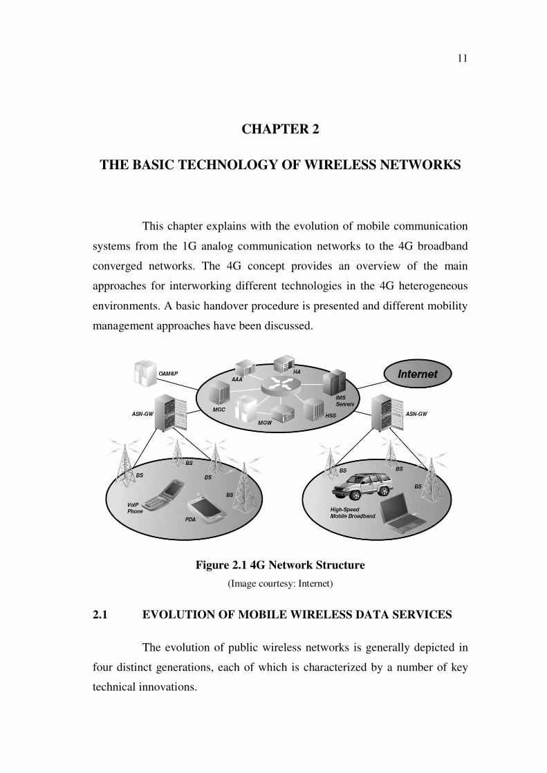
This chapter explains with the evolution of mobile communication
systems from the 1G analog communication networks to the 4G broadband
converged networks. The 4G concept provides an overview of the main
approaches for interworking different technologies in the 4G heterogeneous
environments. A basic handover procedure is presented and different mobility
management approaches have been discussed.
Figure 2.1 4G Network Structure
(Image courtesy: Internet)
2.1 EVOLUTION OF MOBILE WIRELESS DATA SERVICES
The evolution of public wireless networks is generally depicted in
four distinct generations, each of which is characterized by a number of key
technical innovations.
12
2.1.1 First Generation (1G)
In the early 1980s, the first generation networks introduced the
concept of cells to increase the number of channels that could be supported
for transmission. The radio technology was rather rudimentary by current
standards and utilized an analog transmission standard called Advanced
Mobile Phone Service (AMPS); which operated in the 824 to 890 MHz
frequency band. Data options included cellular modems and a packet-based
service called Cellular Digital Packet Data (CDPD) that delivered maximum
data rates around 9600 bps.
2.1.2 Second and Third Generation (2G/3G)
The 2G networks appeared in the early 1990s with the opening of
the 1.9 GHz Personal Communications Service (PCS) bands. This greatly
increased the amount of radio spectrum mobile operators to work with and
spurred a number of successive improvements in network capabilities. The
2G networks made use of digital radio technologies like Code Division
Multiple Access (CDMA), Time Division Multiple Access (TDMA) and
Global System for Mobile Communication (GSM), which supported a far
larger number of calls in the same radio spectrum than 1G AMPS networks.
The move to digital radio technology also allowed for data services like
1xRTT, General Packet Radio Service (GPRS) and Enhanced Data rate for
GSM Evolution (EDGE), which eventually lead to the introduction of even
higher capacity 3G data services, including Evolution Data Optimized
(EVDO), EVDO Revision A (EVDO Rev A), Wireless CDMA (W-CDMA)
and High Speed Packet Access (HSPA).
2.1.3 IP Multimedia Subsystem (IMS)
One important bridge that came about with 3G was the
development of IP Multimedia Subsystem (IMS). IMS describes an IP-based
13
packet core that can interconnect between legacy circuits-based networks and
Internet-type packet services. The transition to 4G will result in
interconnecting 3G and 4G networks for seamless roaming, integration of
wired and convergence services, and a consistent desktop-like user experience
regardless of the access or endpoint.
2.1.4 Fourth Generation (4G)
The 4G WiMAX networks are now being commercially deployed,
and the Long Term Evolution (LTE) standards have recently been finalized.
In the United States, WiMAX is being deployed primarily in the 2.5 GHz
band, while LTE is targeted for the 700 MHz band. Besides operating in
different frequency bands, they use different access protocols.
Apart from the above said characteristics the major attributes that
are common have been given below;
Radio Technology: Both standards utilize Multiple Input-Multiple
Output (MIMO) antenna technologies and incorporate Orthogonal Frequency
Division Multiplexing (OFDM) signal modulation. WiMAX uses OFDM on
both the uplink and the downlink; in LTE networks, the downlink uses
OFDM and the uplink uses a Single Carrier Frequency Division Multiple
Access (SCFDMA). They also make use of adaptive modulation and several
levels of Forward Error Correction (FEC) coding.
Higher Capacity, Greater Reliability: The result of these state of-
the-art radio technologies is far greater bandwidth efficiency (i.e., more bits
per hertz), along with greater reliability. The 4G systems will provide several
times the transmission rate of the 3G systems.
All-IP Core: Where the earlier technologies had been geared
primarily for the requirements of voice, 4G systems will integrate voice and
14
data services over an all-IP architecture. This builds on the earlier
implementation of the IP Multimedia Subsystem (IMS), and will be the key in
integrating all the various media types into a single pipe and integrated user
experience.
2.2 WI-FI AND WIMAX
While describing the evolution of wireless networks, it is also
important to consider another widely successful wireless technology such as
wireless LAN, or Wi-Fi. Wi-Fi and WiMAX share a common ancestry in that
both are products of the Institute of Electrical and Electronics Engineers
(IEEE) 802 committees. Originally focused on wired networks like Ethernet
(i.e., IEEE 802.3), in the mid-1990s the IEEE 802 committees began
expanding their scope to address wireless networks as well. The 802.11
committee had the task of developing the standards for wireless LANs
(WLANs) and the 802.16 committee set to work on standards for wireless
Metropolitan Area Networks (MANs) led to the development of WiMAX.
The IEEE is a worldwide standards body that develops standards using a
process governed by a rigorous set of rules to ensure due process, openness,
consensus and balance. The result is an open standard based on industry-wide
consensus that leads to a larger ecosystem of suppliers, a wider variety of
products and ultimately, to lower costs. So, while Wi-Fi and WiMAX address
different areas of the wireless market, they share the same foundation in a set
of worldwide standards.
2.2.1 WiMAX: The First 4G Technology
WiMAX is nothing but Worldwide Interoperability for Microwave
Access. It describes a 4G metro-area wireless technology defined in the IEEE
802.16 standards and promoted by the WiMAX Forum. The factors preferred
for WiMAX in the 4G environment are Timeframe, Real-World Experience,
Open Standards, WiMAX Forum, Frequency Bands and Global Reach.
15
2.2.2 WiMAX Standards
WiMAX standards defines a wide range of potential
implementation options a mobile operator might choose. While it can lead to
some short-term confusion, it allows mobile operators, great flexibility with
regard to how they deploy a WiMAX network and the services they will be
able to offer. The first are the two different WiMAX standards, defined as
follows;
Fixed Location WiMAX: The original focus of WiMAX
development was for a fixed location radio technology that could be used in
place of cable modem or DSL service for Internet access and possibly other
applications. That fixed location WiMAX is described in the IEEE 802.16
(2004) specifications.
Mobile WiMAX: The specifications also describe mobile WiMAX,
where a user could move through the coverage area and their connection
would be handed off from base station to base station; this mobile version is
described in IEEE 802.16 (2005). 4G is based on the mobile version of
WiMAX, which can provide a fixed-location wireless alternative to DSL and
cable modem services, while also supporting a higher capacity alternative to
mobile cellular 2.5G/3G services. From a technical standpoint, the WiMAX
standards address Layers 1 and 2 of the OSI Reference Model. Layer 1 deal
with the radio transmission specifications and Layer 2 define the access
protocol, security and session establishment functions. The overall design
assumes an all-IP core for the network.
2.2.3 Broadband Wireless Technologies: Comparative Study
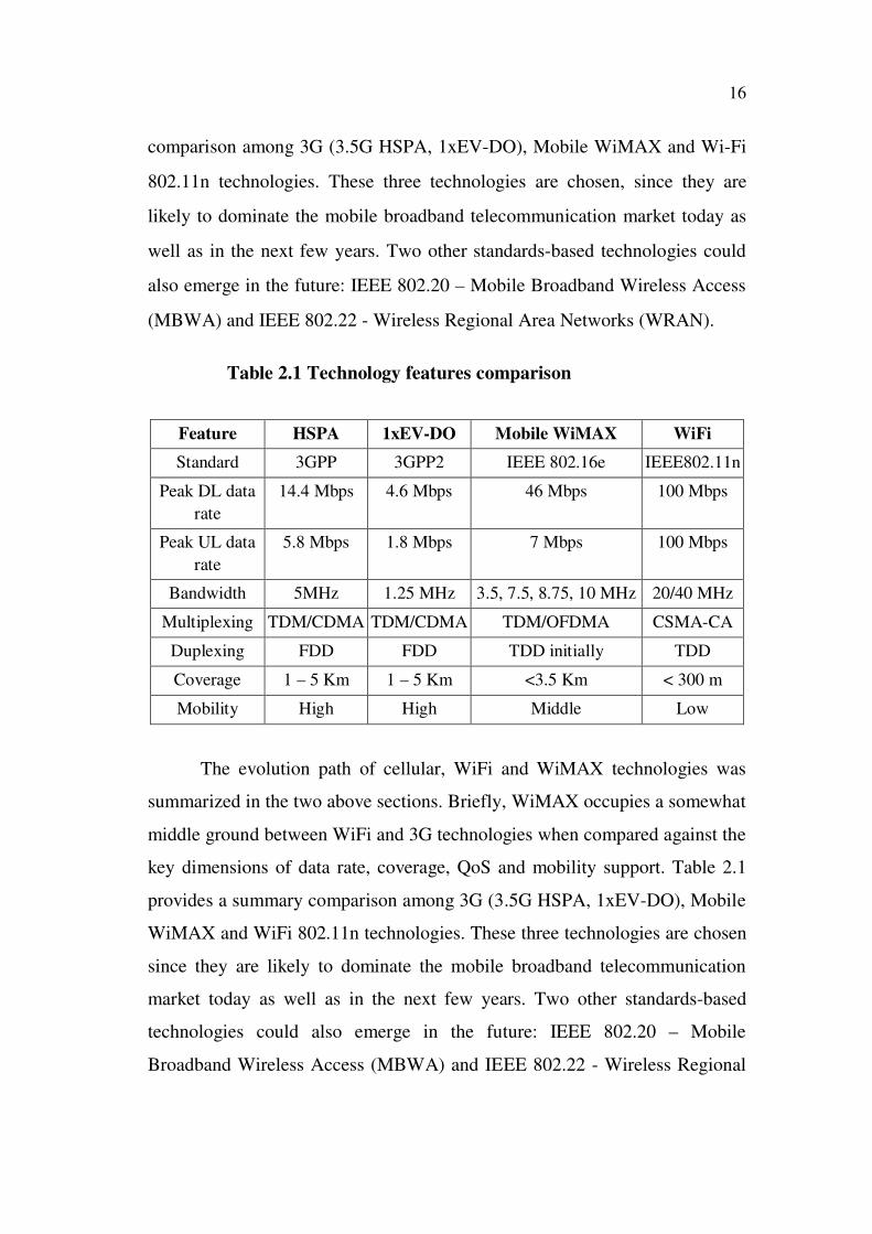
WiMAX occupies a somewhat middle ground between Wi-Fi and
3G technologies when compared against the key dimensions of data rate,
coverage, QoS and mobility support. Table 2.2 provides a summary
16
comparison among 3G (3.5G HSPA, 1xEV-DO), Mobile WiMAX and Wi-Fi
802.11n technologies. These three technologies are chosen, since they are
likely to dominate the mobile broadband telecommunication market today as
well as in the next few years. Two other standards-based technologies could
also emerge in the future: IEEE 802.20 – Mobile Broadband Wireless Access
(MBWA) and IEEE 802.22 - Wireless Regional Area Networks (WRAN).
Table 2.1 Technology features comparison
Feature HSPA 1xEV-DO Mobile WiMAX WiFi
Standard 3GPP 3GPP2 IEEE 802.16e IEEE802.11n
Peak DL data
rate
14.4 Mbps 4.6 Mbps 46 Mbps 100 Mbps
Peak UL data
rate
5.8 Mbps 1.8 Mbps 7 Mbps 100 Mbps
Bandwidth 5MHz 1.25 MHz 3.5, 7.5, 8.75, 10 MHz 20/40 MHz
Multiplexing TDM/CDMA TDM/CDMA TDM/OFDMA CSMA-CA
Duplexing FDD FDD TDD initially TDD
Coverage 1 – 5 Km 1 – 5 Km <3.5 Km < 300 m
Mobility High High Middle Low
The evolution path of cellular, WiFi and WiMAX technologies was
summarized in the two above sections. Briefly, WiMAX occupies a somewhat
middle ground between WiFi and 3G technologies when compared against the
key dimensions of data rate, coverage, QoS and mobility support. Table 2.1
provides a summary comparison among 3G (3.5G HSPA, 1xEV-DO), Mobile
WiMAX and WiFi 802.11n technologies. These three technologies are chosen
since they are likely to dominate the mobile broadband telecommunication
market today as well as in the next few years. Two other standards-based
technologies could also emerge in the future: IEEE 802.20 – Mobile
Broadband Wireless Access (MBWA) and IEEE 802.22 - Wireless Regional

17
Area Networks (WRAN). Brief introduction about these two under
development standards:
• Much like 802.16e, the IEEE 802.20 hopes to define a broadband solution
for vehicular mobility up to 250 km/h. The 802.20 standard was being
positioned as an alternative to 3G cellular services since it can support high-
speed handover and wireless network access. It is likely to be defined for
operation below 3.5GHz to deliver peak user data rates in excess of 4Mbps
and 1.2Mbps in the downlink and uplink respectively. At this point in time,
the standard seems to be suspended owing to lack of consensus on technology
and issues with the standardization process.
• The IEEE 802.22 standard aims to bring broadband access to rural and
remote areas. The basic goal of 802.22 is to define a cognitive radio that can
take advantage of unused TV channels in sparsely populated areas. Operating
in the VHF and low UHF bands provides favorable propagation conditions
that can lead to greater range (100km). The 802.22 standard is steadily
processing and results are expected soon. 4G technology has not been
officially defined yet. Most companies believe that the characteristics of IMT-
Advanced, as defined by ITU, will represent a definition of 4G. Two expected
requirements within IMT-Advanced are OFDMA-based technology and data
rate support of 100Mbps for mobile applications. LTE, UMB, and WiMAX
802.16m all fulfill these requirements. Although several companies claimed
that LTE/UMB/WiMAX 802.16m was 4G, hereafter they are considered as a
pre-4G technology. Any claim that a particular technology is a 4G technology
is, in reality, simply a market positioning statement by the respective
technology advocate. A comparison among the three emerging technologies is
presented in Table 2.2.
18
Table 2.2 Pre-4G technology requirements comparisons
Feature LTE UMB WiMAX 802.16m
Peak data rate
(per sector
@20MHz)
DL:288Mbps(4x4)
UL:98Mbps(2x4)
DL:250Mbps(4x4)
UL:100Mbps(4x4)
DL:~350Mbps(4x4)
UL:~200Mbps(2x4)
Latency Link-Layer
Access:<5ms
Handover:<50ms
LLA:<10ms
Handover:<20ms
LLA:<10ms
Handover:<20ms
MIMO2
configuration
DL:2x2,2x4,4x2,4x4
UL:1x2,1x4,2x2,2x4
DL:2x2,2x4,4x2,4x4
UL:1x2,1x4,2x2,2x4
DL:2x2,2x4,4x2,4x4
UL:1x2,1x4,2x2,2x4
Bandwidth
(MHz)
1.25,1.6,2.5,5,10,15,20 1.25 to 20 5,10,20,40
Duplexing TDD,FDD TDD,FDD TDD,FDD
Multiplexing OFDMA and SC-
FDMA
OFDMA SOFDMA
Mobility Up to 350 Km/h Up to 250 Km/h Up to 350Km/h
2.3 4G WIRELESS MOBILE HETEROGENEOUS NETWORKS
Unlike 1G, 2G and 3G, 4G is not a set of formally agreed end-to-
end standards developed in the traditional top-down way that the
telecommunications industry has used for years as given by Ahlund et al
(2006). It is now widely accepted that 4G is a vision of an all-IP based,
heterogeneous mobile broadband networks with multiple air interfaces,
converged into fixed-mobile networks, and multiple devices with multi-mode
capabilities. 4G will provide end-users with an Always Best Connected
(ABC) facility, low latency and high QoS broadband experience. ABC means
a seamless service provisioning across a multitude of wireless access systems
and an optimum service delivery via the most appropriate available network.
4G will be a convergence platform providing clear advantages in terms of
coverage, bandwidth and power consumption. 4G will ensure the seamless

19
mobility and global roaming among various access technologies such as
cellular networks, Wi-Fi, WiMAX, satellite and Digital Video Broadcasting
Handheld (DVB-H). 4G services will be end-to-end with QoS, high security,
available at any time, anywhere with seamless mobility, affordable cost,
single billing, and fully personalized.
2.3.1 Motivations for 4G Heterogeneous Networks
As mentioned previously, the 4G mobile networks does not consist
of only one access technology but have multiple ones. It is needed to have a
mechanism that enables seamless mobility among different systems. The
motivation behind the heterogeneous networks comes from the fact that there
is no technology that could offer ubiquitous coverage. No technology can
provide simultaneously the high bandwidth, low latency, high mobility and
wide-area data service to a large number of users. As all these systems have
their own advantages and shortcomings, no single technology merits enough
to replace all other existing technologies up to now, even pre-4G
technologies. It is beneficial for mobile users to switch their connection
among different access points of different technologies to maintain the
connectivity all time, and to enjoy the best personalized services according to
their own preferences. During the evolution from the 1G to the pre-4G, a
range of mobile wireless technologies have been developed.
All these technologies were designed independently, targeting
different types of services, data rates and users. The complementary
characteristics of various technologies motivate the interest to integrate them
together. An interworking approach can make the best use of the advantages
of all technologies and can eliminate their stand-alone defects. For example,
an operator can deploy low-cost high-data rate WLAN/WiMAX that is either
an extension of cellular network or inter-workable with cellular network so
that the utilization of already deployed infrastructures can be maximized. The
20
wireless broadband technologies like Wi-Fi, WiMAX can be a good
complement to cellular technologies in terms of geographical coverage and
QoS. If one access technology is highly loaded, users can connect to another
access technology to have the equivalent services. Also, if a user requires a
higher QoS level which is not supported by its current access technology, it
can automatically be handed over to another technology. These are the main
motivations for research as well as business exploration of 4G convergence
concept.
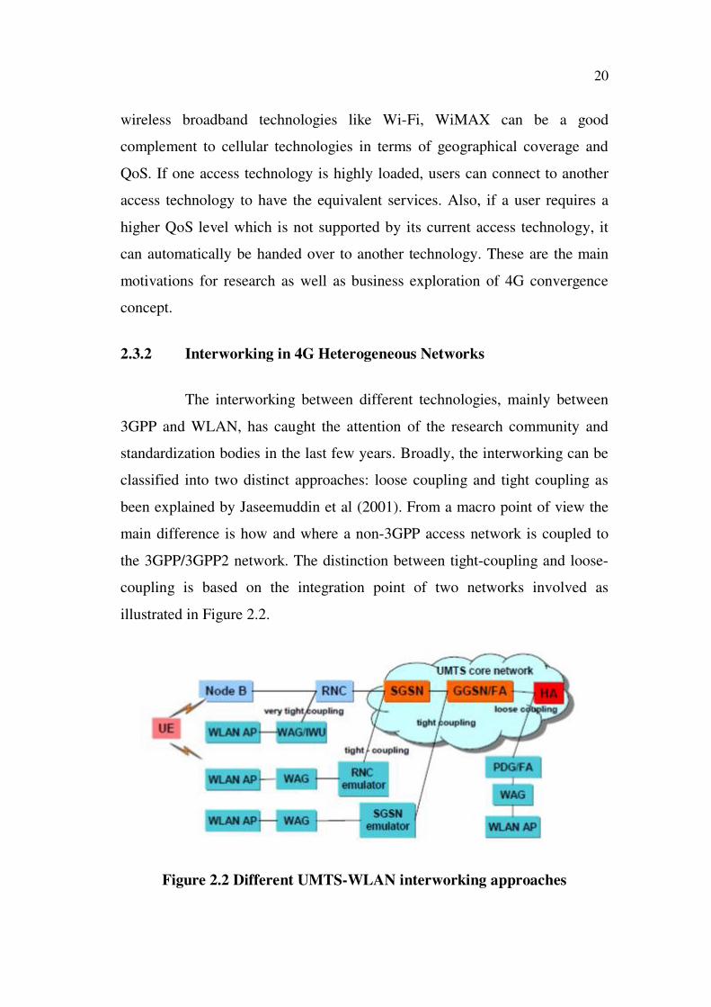
2.3.2 Interworking in 4G Heterogeneous Networks
The interworking between different technologies, mainly between
3GPP and WLAN, has caught the attention of the research community and
standardization bodies in the last few years. Broadly, the interworking can be
classified into two distinct approaches: loose coupling and tight coupling as
been explained by Jaseemuddin et al (2001). From a macro point of view the
main difference is how and where a non-3GPP access network is coupled to
the 3GPP/3GPP2 network. The distinction between tight-coupling and loose-
coupling is based on the integration point of two networks involved as
illustrated in Figure 2.2.
Figure 2.2 Different UMTS-WLAN interworking approaches

21
2.4 INTERWORKING ARCHITECTURE
2.4.1 Loose-coupling Architectures
Loose coupling offers a common interface for the exchange of
information between the networks to guarantee service continuity. Loose
coupling refers to the IP layer interconnection. The basic loose coupling
interworking architecture between WLAN and UMTS is depicted in
Figure 2.3. WLAN and UMTS are assumed to be in different IP address
domains. The IP address is changed when the mobile terminal moves from
one network to another. The heterogeneity of different access networks is
managed and hidden by Mobile Internet Protocol (MIP). The integration point
is the home agent of the MIP mechanism implemented in the Internet/external
Packet Data Network (PDN). In general, the interworking point is placed after
Gateway GPRS Support Node (GGSN).
Figure 2.3 3GPP -WLAN loose coupling interworking architecture
In the loose coupling interworking, the two networks communicate
through the Internet. They operate independently of each other and roaming
agreements between the corresponding operators are required to be
22
established. To ensure service continuity with roaming capabilities, MIP and
Authentication, Authorization and Accounting (AAA) functionalities are
combined. The existing AAA solution in 3GPP network is used for managing
and exchanging subscriber information and credentials between 3GPP and
non-3GPP access networks. This approach separates completely the data path
in WLAN and 3GPP networks. If two access technologies are deployed by a
single operator, the Packet Data Gateway (PDG) may interface directly to the
GGSN for signaling, otherwise, the signaling will be transported through the
IP network.
The key of mobility management of this architecture is the MIP.
The foreign agents are located in the GGSN and the PDG while the home
agent is located in the PDN/Internet. When the mobile user moves across the
networks, its home address is maintained. The major drawbacks are the
handover latency and the packet loss due to MIP mechanism. In order to solve
this problem, pre-registration, pre-authentication, packet buffering and
forwarding techniques have been studied. Many extensions of MIP have been
proposed such as: Fast MIP, Hierarchical MIP, multiple Care of Address
(CoA) registration MIP, layer-2 triggering based MIP, etc. The loose coupling
interworking architecture offers an easy and independent deployment. The
loose-coupling interworking does not need drastic changes in the existing
infrastructures. There exists a variant of the loose coupling interworking that
is sometimes referred to as an open coupling. In the latter scheme, no real
integration between the two networks is present. WLAN and 3GPP are two
independent systems that share a single billing scheme.
2.4.2 Tight-coupling Architectures
In the tight coupling scheme, the non-3GPP access network is
employed as a new radio access technology within the cellular one. The tight
coupling makes two different Radio Access Technology (RAT)s working

23
together with a single core network. The interworking point is at the 3GPP
core network or at the UMTS Terrestrial Radio Access Network (UTRAN) as
illustrated in Figure 2.2. When the integration point locates in the UTRAN,
the interworking is known as a very tight coupling as explained by Vulic et al
(2005). The 3GPP control protocols are reused in the WLAN and the data
traffic is routed via the 3GPP core network to the outer entities. Two radio
access networks are interconnected via layer 2. All the layer 3 protocols
remain unchanged. The handover does not involve the change of remote IP
address as well as the AAA policies. In the interworking reference model
architecture depicted in Figure 2.4, the Radio Network Controller (RNC)/
Serving GPRS Support Node (SGSN) emulator provides functionalities that
are equivalent to those of an RNC/SGSN in an attempt to hide WLAN access
network particularities from the UMTS. Its main function is to provide a
standardized interface to the UMTS core network.
Figure 2.4 3GPP-WLAN interworking architecture using TTG
In the very tight-coupling solution, the WLAN is considered as part
of the UTRAN. An important issue with the very tight-coupling scheme is the
ownership of the WLAN. The most envisioned solution is that the 3GPP
operator owns the WLAN part. Due to the scalability issue, it makes sense to
introduce an Interworking Unit (IWU) between the WLAN Access Point
(AP)s and the RNC to share the control task of the RNC. The IWU

24
(Interworking Unit) will be implemented in the WLAN AP to either act as a
pure traffic concentrator or be further responsible for control and supervision
functionality as in Vulic et al (2005).
The TTG(Transmit/receive Transition Gap) can be considered as an
SGSN emulator Bernardin et al (1997). The functionality of TTG covers all
aspects of PDG that are not covered by the GGSN. The TTG acts as the
SGSN for the GTP(GPRS Tunneling Protocol) tunnel establishment. It also
acts as a WLAN user’s proxy for the reason of transparency to the WLAN. In
this scheme, the end-to-end tunnel from Mobile Subscriber (MS) to PDG is
terminated at TTG and a GTP tunnel is established between the TTG and
GGSN. The TTG supports location management and session management
mechanisms such as SGSN context transfer, Packet Data Protocol (PDP)
context update, and Home Location Register (HLR) update. This solution
allows the re-use of existing GGSN and its existing capabilities such as
charging frameworks. It offers a full interoperability with existing SGSN
without upgrades. This solution satisfies service continuity requirements with
little handover delay and no packet overhead. However, it requires a new
network element TTG to be implemented.
2.5 MOBILITY MANAGEMENT IN HETEROGENEOUS
NETWORKS
2.5.1 Link Layer Mobility Management
The term link layer (L2) refers to everything that is below the IP
layer. The L2 mobility management mechanism allows the mobile node to
roam among different physical points of attachment while the point of
attachment to IP network remains the same. The link layer mobility solutions
are more or less link technology specific, for instance both IEEE 802.11f and
GPRS networks can provide link layer mobility. In this mobility management
25
scheme, no IP sub-network configuration is required upon movement. But
some IP signaling may be required for the mobile node to confirm whether or
not there was a change of the wireless access node. For example, an 802.11
network consists of several APs interconnected by means of a distribution
system. When the Signal-to-Noise Ratio (SNR) drops below a certain
threshold, the mobile node scans for the best available AP in the L2 network
and re-associates with it. An L2 update frame is broadcasted in order to
register the mobile node’s current location with all bridges and switches in the
distribution system. This L2 handover in WLAN was proposed in IEEE
802.11f amendment.
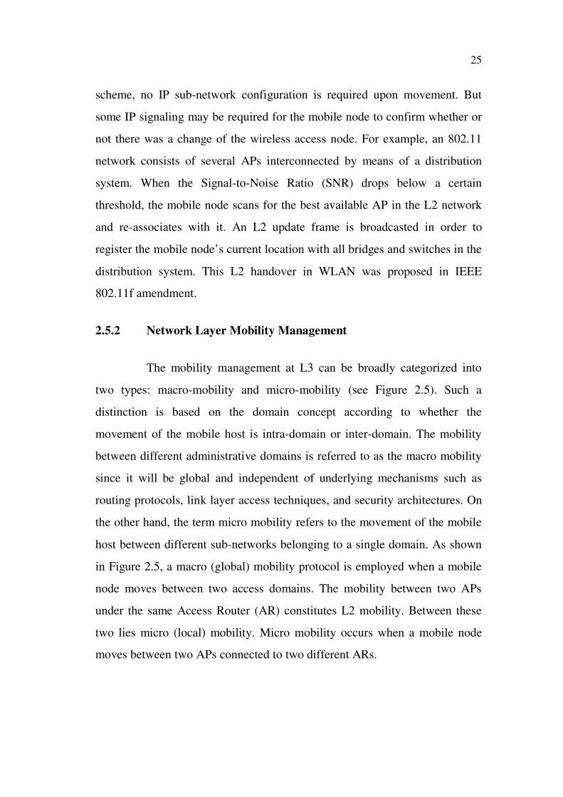
2.5.2 Network Layer Mobility Management
The mobility management at L3 can be broadly categorized into
two types: macro-mobility and micro-mobility (see Figure 2.5). Such a
distinction is based on the domain concept according to whether the
movement of the mobile host is intra-domain or inter-domain. The mobility
between different administrative domains is referred to as the macro mobility
since it will be global and independent of underlying mechanisms such as
routing protocols, link layer access techniques, and security architectures. On
the other hand, the term micro mobility refers to the movement of the mobile
host between different sub-networks belonging to a single domain. As shown
in Figure 2.5, a macro (global) mobility protocol is employed when a mobile
node moves between two access domains. The mobility between two APs
under the same Access Router (AR) constitutes L2 mobility. Between these
two lies micro (local) mobility. Micro mobility occurs when a mobile node
moves between two APs connected to two different ARs.
26
Figure 2.5 Micro vs. Macro Mobility Management
2.5.2.1 Macro Mobility
When a mobile node moves between the different subnetworks or
different domains, its IP address will be changed. In order to maintain the
connectivity, the mobile node should have a mechanism to inform quickly its
corresponding node about its new address or it should have a permanent IP
address given by its corresponding node. Tseng et al (2003) proposed MIPv4
(Mobile Internet Protocol version 4) to solve the problem of node mobility.
MIP is a standard that allows a user with a mobile device, whose IP address is
associated with a particular network, to remain connected when moving to a
network with a different IP subnetwork address. It is designed around two
components namely, home agent and foreign agent. The home agent
maintains the database of current locations of all the mobile terminals under
its control. When the mobile node moves away from the home network to a
foreign network, the home agent updates the current location of the mobile
node with the address of the foreign agent (called CoA). When a packet is
addressed to the mobile node, it first reaches the home agent, then the home
agent encapsulates this packet with the foreign agent address as a destination.

27
Upon receiving this packet, the foreign agent removes the IP header
information inserted by the home agent and sends the packet to the mobile
node. An address translator implemented in the home agent and a tunnel
between the home agent and the foreign agent are required. Shortly, MIP
keeps track of the location of the mobile node and delivers packets to its
current location. MIPv6 (Mobile Internet Protocol version 6) prescribed by
Montavont et al (2002) includes many features for mobility support that are
missing in MIPv4. MIPv6 can support the vertical handover in the network
layer without the need of foreign agent and address translator. MIPv6 uses
two separate IPv6 addresses: the home address (HoA) as identifier and the
CoA as locator. On its home link, the mobile node uses its HoA just like a
stationary node. When the mobile node moves to a foreign link, it configures
a CoA with the foreign prefix. It can provide a transparent movement to the
transport and upper layers. Besides the MIP, new Internet Engineering Task
Force (IETF) work on the global mobility management protocols has
proposed Host Identity Protocol (HIP), Moskowitz et al (2006) and IKEv2
(Internet Key Exchange version 2 protocol) Mobility and Multihoming
MOBIKE (MOBile Internet Key Exchange) solutions.
The HIP provides a method of separating the end-point identifier
and locator roles of IP addresses. In HIP, the Host Identifier (HI) is the public
key of a public-private key pair. The HI is represented with a 128-bit long
Host Identity Tag (HIT) that is created by taking a cryptographic hash over
the corresponding HI. Since each HIT can be mapped dynamically to multiple
IP addresses, HIP enables mobility and multi-homing. Handover management
is carried out by means of direct peer notifications. Location management is
provided by rendezvous servers. In fact, the HIP solution introduces a HIP
layer between IP layer and transport layer. The upper layer sockets are bound
to host identifiers instead of IP addresses. Thus, the HIP is sometimes referred
to as a L3.5 mobility management.
28
The MOBIKE protocol facilitates Virtual Private Network (VPN)
users to change from one address to another without re-establishing all
security associations, or to use multiple interfaces simultaneously. The
MOBIKE protocol is assumed to work on top of Internet Key Exchange
version 2 protocol (IKEv2). It allows changing an IP address associated with
IKEv2 and an IPsec tunnel to change without reusing IKEv2 from scratch.
2.5.2.2 Micro mobility
To enhance the Mobile IP, the so-called micro mobility protocols
have been developed to manage handovers within a single administrative
domain. The micro mobility solutions aim to reduce the signaling overhead
and the handover latency of the MIP mechanism. Two kinds of approaches
are distinguished as: tunnel-based and routing table-based. The tunnel-based
solutions consist on using the local and hierarchical registration. The tunnel-
based solutions include Hierarchical MIP (HMIP), Soliman et al (2007), Fast
MIP (FMIP) and Intra-Domain Mobility Management Protocol (IDMP),
Misra et al (2002).
The HMIP is designed to minimize the signaling overhead to the
corresponding node and the home agent. This is achieved by allowing the
mobile node to locally register with a domain, named local mobility zone.
These zones form the independent subnetwork domains which are connected
to the Internet via a Mobility Anchor Point (MAP). The MAP acts as a local
home agent of the mobile node. When the mobile node moves inside the local
MAP domain, it only needs to register the new location with the MAP. The
handover is thus hidden at the home agent and the corresponding node. The
FMIPv6 (Fast Mobile Internet Protocol version 6) is an extension of MIPv6
that allows the mobile node to configure a new CoA before it moves to the
new network and thus can use it immediately once connecting to the new
network. The FMIPv6 can reduce the latency involved during the mobile
29
node’s binding update by providing a bi-directional tunnel between the old
and the new AR. When the mobile node switches to the new link, the previous
AR routes all packets to the new mobile node’s CoA. Therefore, the mobile
node updates its location and receives packets in parallel.
The routing-based solutions consist of maintaining host-specific
routes in the routers to forward packets. The host-specific routes will be
updated based on the host mobility information. Cellular IP (CIP), Campbell
et al (2002) and Handoff Aware Wireless Access Internet Infrastructure
(HAWAII) are the two examples of the routing-based micro-mobility
protocols. A CIP system consists of a number of components to allow access,
paging and mobility management. The concept behind CIP is similar to the
mobility management of voice terminals in GSM. Its goal is to allow the idle
mobile node to have discontinuous transmissions. As long as mobile nodes
can be traced within a paging area, they do not have to register every move
during passivity. A visiting mobile node must register to the gateway and use
its IP address as its care-of address. All the packets destined to the mobile
node first reach the gateway from which they are routed to their respective IP
address.
2.5.3 Host-based vs. Network-based Mobility
Most of the proposed micro mobility protocols like FMIPv6 and
HMIPv6, Soliman et al (2007) are host-based solutions as they require host
involvement at the IP layer. A new protocol that is network-based and that
requires no software on the host is therefore desirable. The distinction
between host-based and network-based mobility solutions is illustrated in
Figure 2.6. The network-based mobility solution is a topic that has had a lot of
attention within the IETF Network-based Localized Mobility Management
(NETLMM) working group.

30
Figure 2.6 Host-based vs. Network-based Mobility
Proxy MIPv6 (PMIPv6) (Gundavelli et al 2008) has been
designated as the network-based localized mobility management protocol.
The PMIPv6 protocol introduces a new entity, the Proxy Mobile Agent,
which is a kind of MIPv4 foreign agent sitting on the AR, also known as
Mobile Access Gateway (MAG). Between AR and mobile node, a secure
point-to-point link will be established. The MAG will handle mobility on
behalf of the mobile node, using functionality similar to MIPv6’s. Because of
the use and extension of MIPv6 signaling and home agent functionality, this
protocol is referred to as Proxy MIPv6. The MAG is responsible for detecting
the mobile node’s movements to and from the access link and initiating
binding registrations to the mobile node’s Local Mobility Anchor (LMA).
The mobile node may operate in an IPv4-only mode, IPv6-only mode or in
dual IPv4/IPv6 mode.
When the mobile node changes its point of attachment, the MAG
on the previous link will detect the mobile node’s detachment from the link
and will notify the LMA. The MAG will remove the binding and routing state
for that mobile node. The MAG on the new access link upon detecting the
31
mobile node on its access link will notify the LMA for updating the binding
state. Once that signaling is complete, the mobile node continues to receive
the Router Advertisements containing its home network prefix. Accordingly,
the mobile node believes that it is still on the same link and it will use the
same address configuration on the new access link.
2.5.4 Upper Layer Mobility Management
Mobility management has also been considered at layers above IP
(upper layers). For instance, the Transmission Control Protocol (TCP)-
Migrate (Snoeren et al 2000) adds mobility support to TCP sessions.
Specifically, it implements extensions to the TCP protocol, so that TCP
sessions can continue without interrupt when an endpoint changes its point of
attachment. Similarly, mobile Stream Control Transmission Protocol (SCTP),
Koh et al (2007) build upon the features of the SCTP transport protocol to
offer transport layer mobility. Seamless mobility is inherent in the SCTP and
is achieved through the multi-homing support feature of the SCTP and some
of its extensions (e.g., Dynamic Address Reconfiguration), Stewart et al
(2007). The mobility management at the application layer has also been
studied. The most well-known solution is the Session Initiation Protocol
(SIP)-based mobility management, IETF (2002). In this approach, the
infrastructure of SIP is reused for mobility purposes. To make handover, the
mobile node sends a re-INVITE message with its new address to its
corresponding node using the same call identifier as in the original setup,
Dutta et al (2004). The handover delay in a SIP-based mobility includes the
L2 delay, the IP address configuration delay and the time required by the RE-
INVITE message to reach the corresponding node. The common factor in
these approaches is that they apply to specific protocols and applications and
do not cover the full spectrum of Internet applications.
32
2.5.5 Cross-layer Mobility Management
The handover latency of MIP is due to the movement detection and
registration. The proposed micro-mobility can only solve the latter one. By
using the link layer information such as signal strength, the latency for
handover detection can be reduced. The information from the link layer can
also be used to notify the network to prepare the handover in the target
network and to initiate the L3 handover procedure. Some algorithms use
signal strength measurements directly to reduce handover latency (Yokota
et al 2002), while others track the mobile nodes via the received signal
strength and use this tracking information to support low-latency MIP
handover (Hseih et al 2003).
A seamless handover architecture for MIP, S-MIP (Seamless
handoff MIP), Hseih et al (2003) provides a way to combine a location
tracking scheme and the hierarchical MIP handover to enhance the
management process. The use of L2 hints for L3 handover has been widely
explored in the literature. It refers to a L2/L3 cross-layer mobility
management approach. In the cross-layer perspective, the combination of MIP
(network-layer protocol) and SIP (application layer protocol) has been
investigated by Politis et al (2003), and Wang et al (2005). In this scheme,
handover occurs at the network layer enabling connection oriented traffic to
reach the destination using MIP. In parallel, the SIP peer is notified about the
handover by using re-INVITE with the new CoA address indicated in the
Contact field.
Real-time traffic can be sent directly between peers avoiding
suboptimal paths. One can recognize that a single layer-specific mobility
management protocol can hardly provide the advanced mobility support in
heterogeneous networks. The intrinsic reason is that mobility brings about
significant impacts on each layer, which in turn has its convenience to deal
33
with different level of mobility impacts. A multi-layer architecture that can
make full use of each layer’s contributions while still keeping the basic
structure of the protocol stack is highly demanded (Wang et al 2003).
2.6 CHAPTER SUMMARY
4G is built on an all-IP core network, which brings the mobile
network into a step with the overall directions in enterprise networking. 4G
moves wireless performance to a new level while offering speed, reliability
and security on par with wired network connections. The functions are
summarised as follows;
WiMAX uses IEEE-developed open standards, allowing the
entire industry to design, build and integrate WiMAX-
compatible products and services.
Interworking of heterogeneous networks is taking the
advantageous of user service continuity.
To provide seamless mobility over heterogeneous networks, it is
very important to provide low latency handover.
The cross-layer mobility management approach and the
hierarchical mobility management seem to be a good way to
manage the mobility.
A global view of the mobile network evolution from the first
generation towards the next future generation likely to be
characterized by the interworking of heterogeneous access
networks is addressed.
The mobility management, one of the key rules for the success
of such a convergence, has been introduced.


![(D) HK Normalien Aktuell [GB] · DIN 9825/ISO 9182-2 D14 202.17. Guide Pillars with Ball Cage Retainer 202.22. 202.23. 202.24. Guide Pillars ~DIN 9825/ ~ISO 9182 press-in type, with](https://img.dokumen.tips/doc/110x75/5f791372328ac07cbf58eebc/d-hk-normalien-aktuell-gb-din-9825iso-9182-2-d14-20217-guide-pillars-with.jpg)