Embed Size (px)
Citation preview
Chapter 2
DISPLACEMENT OF STATICALLY
DETERMINATE PLANE TRUSSES
Bambang Prihartanto Shahrul Niza Mokhatar
2.1 PRINCIPLE OF ENERGY/WORK
The energy is referred to Strain Energy, U.
If a set of external loads is applied to a deformable/elastic structure, the points of application of the loads move and each of the members making up the structure becomes deformed.
So, we can state that the work has been performed on the structure by the
external load. The work is called external work.
Elements of the structure also try to perform the work to prevent the deformation. The work is called internal work.
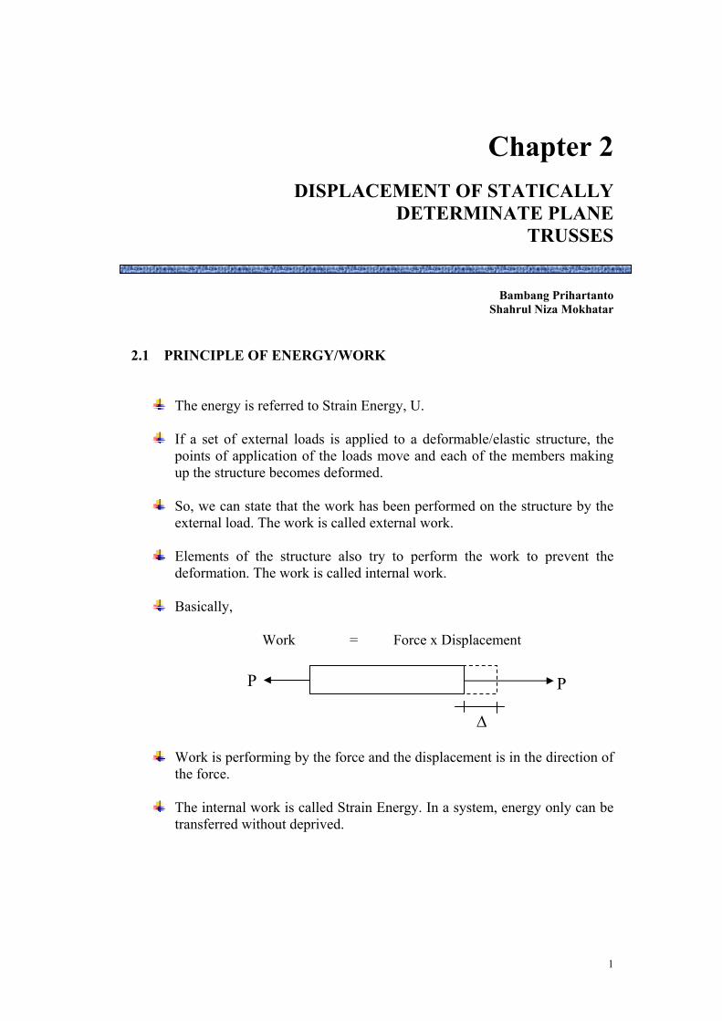
Basically,
Work = Force x Displacement
P P
Δ
Work is performing by the force and the displacement is in the direction of the force.
The internal work is called Strain Energy. In a system, energy only can be
transferred without deprived.
1

Deflection,Δ
P1
Load,P
Δ1 dΔ
P1 α Δ1 P1 = k.Δ1
If the load is increasing to P1
Work = P∫Δ1
01 dΔ
P1 = kΔ1
∴ Work = (kΔ∫Δ1
01 ) dΔ
= kΔ12
2
Substitute k =1
1PΔ
,
∴ Work, w = ½ P1Δ1 * This is the area below the graph from 0 to Δ1. * If P1 is located for displacement Δ1, Work, w = P1Δ1
From the Conservation Of Energy Principle, work performed on the structure must equal to work done by the internal force to the element.
∴ External Work = Internal Work
2

Internal work will caused the deformation (strain). It also named as strain energy.
External Work = Strain Energy W = U = ½ PΔ
Deformation, Δ = AEPL
∴ U = ½ P(AEPL ) =
AELP
2
2
2.2 PRINCIPLE OF VIRTUAL WORK
Previous section was discussed that the real work only suitable for finding the displacement at points subjected to the load. For others points/locations, modification can be done by virtual work method / Unit-load Method.
Virtual work method can be use to determine the displacement of a truss
joint when the truss is subjected to an external loading, temperature change, or fabrication errors.
Consider a truss in figure below, it is desired to calculate the vertical
deflection of point C.
A B
C
∆C
Before Δ occurred, we apply a 1 unit vertical load to this point of the dummy structure as indicated in figure below.
3

A B
C
1
Due to the unit load was apply when Δ occurred. So, External work =1. Δ.
Let F represent the internal forces in the real truss and μ is the internal forces in the dummy structure due to one unit load. If the length, area, and modulus of elasticity of a bar in the truss are designated by L, A, and E.
If force, F apply in one member of trusses,
AE
L.FdL =
F F
L dL
A,E
Internal work done by μ for all members are :
∑ ⎟⎠⎞
⎜⎝⎛μ
AEL.F.
External Work = Internal Work
1. Δ = ∑ ⎟⎠⎞
⎜⎝⎛μ
AEL.F.
∴ Δ = ∑(F.μ.L ) A.E
Thus, the steps to find the deflection at joint C for the truss above are :
4
1. Determine all forces in the truss member due to the external forces. 2. Replace the external load with 1 unit load at joint C in the vertical
direction to find the internal forces (μ).
3. Calculate the (AE
L..F μ ) value for each member and add.
If the value of (AE
L..F μ ) is positive then this shows that the direction
of the deflection is the same as the direction of the unit load Revision
In BFC 2083, all of you were studied the basic of truss statically determinate in calculating the member forces using Method of Joint, Method of Section and Alternative Method. For the time constraint, please do more exercise in solving the member forces by using the third method.
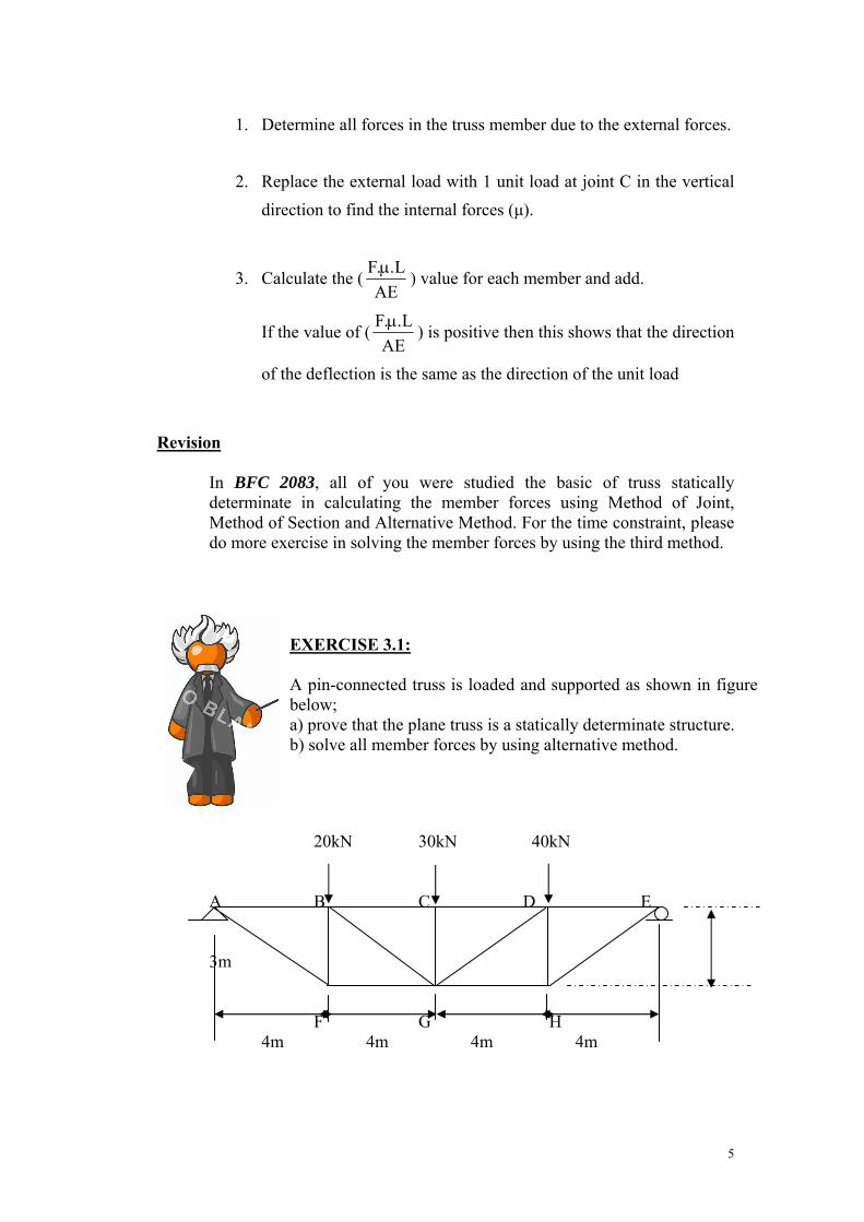
EXERCISE 3.1: A pin-connected truss is loaded and supported as shown in figure below; a) prove that the plane truss is a statically determinate structure. b) solve all member forces by using alternative method.
20kN 30kN 40kN A B C D E 3m F G H 4m 4m 4m 4m
5

EXAMPLE 2.1 The cross sectional area of each member of the truss shown in figure below is A= 400mm2 and E=200GPa. Assume the members are pin connected at their ends. Determine;
a) the vertical displacement of joint C if a 4kN horizontal force is applied to the truss at C.
C 4 kN 3m A B 4m@ 2 Solution: Determine whether the truss is statically determinate or indeterminate. = m + r – 2j If the truss is statically determinate, continue this step. Calculate the Real Forces,F.
C 4 kN 3m
HA A B VA 4m@2 VB
F = F
4
VA + VB = 0 2.5 (2.5)
+ MA; = - VB(8) + 4(3)
12 = 8Vb 4 VB = 1.5kN ( ) VA= -1.5kN 2
= 1.5kN ( ) 1.5 1.5
6

Find the vertical displacement of joint C. Calculate the Virtual Forces, μ. All origin forces are neglected assumed and one unit load method is applied at C. 1 kN
C 3m A B 4m@2
F = F
VA + VB = -1 1
+ MA;
= - VB(8) – 1(4) VB = -0.5 kN 0.836 0.836
= 0.5kN ( ) VA = -0.5 kN
= 0.5kN ( ) (0.67) 0.5 0.5
All Real Forces, F and Virtual Forces, μ values are listed in schedule.
MEMBER L(m) F(kN) μ(kN) NnL AB 8 2 -0.67 -10.72 AC 5 2.5 0.836 10.45 CB 5 -2.5 0.836 -10.45
Σ= -10.72
a) Vertical displacement at C;
E = 200 GPa = 200 x 106 kN/m2
A = 400 mm2 x 1 m2 = 4 x 10⁻⁴ m2
10002 m2
AE = 80 000 m2
1kN ΔVC = Σ Fμ L AE ΔVC = ?
7

EXAMPLE 2.2 Determine the vertical displacement at joint E of the truss shown in figure below. The modulus of elasticity for each member is E = 210 kN/mm2 and the data is follow: Member L (x102 mm) A (x104 mm2) Member L (x102 mm) A (x104 mm2)
AH 180 2 DE 202 3 HG 180 2 BH 90 1 GF 180 1 BG 202 1.5 FE 180 1 CG 180 3 AB 202 3 GD 202 1.5 BC 202 4 DF 90 1 CD 202 4
A
B
C
HG
D
F E
20 kN 20 kN 20 kN
18 m
18 m 18 m 18 m 18 m Solution :
The internal forces of members due to the real load of 20 kN at joint E, F and H is applied.
Support reaction : RA = -20 kN
A
B
C
H G
D
F E
20 kN 20 kN 20 kN
(67.1)(67.1)
RG = 80 kN
20 kN 80 kN
(44.7) (44.7) (20) (20)
(-40) (-40) (-40)
(-22.4) (-22.4)
(-60)
(-40)
8

Determine the vertical displacement at joint E. The forces of members due to the unit load, 1 kN at joint E is applied.
A
B
C
H G
D
F E
1 kN1 kN
(2.24)(2.24)
Support reaction : RA = -1 kN RG = 2 kN
Table of ΔE = (AE
L..F μ)
Member L (x 102 mm)
A (x 104 mm2)
L/A F (kN) μ FμL/A
AH 180 2 0.9 -40 -2 72
HG 180 2 0.9 -40 -2 72
GF 180 1 1.8 -40 -2 144
FE 180 1 1.8 -40 -2 144
AB 202 3 0.67 44.7 2.24 67.3
BC 202 4 0.51 67.1 2.24 75.8
CD 202 4 0.51 67.1 2.24 75.8
DE 202 3 0.67 44.7 2.24 67.3
BH 90 1 0.9 20 0 0
BG 202 1.5 1.35 -22.4 0 0
CG 180 3 0.6 -60 -2 72
GD 202 1.5 1.35 -22.4 0 0
DF 90 1 0.9 20 0 0
∑ = 790.2
2 kN
(2.24) (2.24) (0) (0)
(-2) (-2) (-2)
(0) (0)
(-2)
(-2)
9

The vertical displacement at joint E;
ΔE = ∑ (AE
L..F μ) = 790.2 / 210 = 3.76 mm
EXAMPLE 2.3 Determine the vertical displacement at joint E of the truss shown in figure below. The modulus of elasticity of each member is E = 200 kN/mm2 and the cross-sectional area of each member is A = 1000 mm2
20 kN
40 kN
40 kN
E C
D
A
B 2
Solution :
The forces of members due to the real load at E and C is applied
m 2 m
3 m
20 kN
40 kN
40 kN
E C
D
A
B 2 m 2 m
3 m
100 kN
80 kN
+73.3
- 66.7
+100
- 48.1
- 66.7
+ 80
80 kN
0
10
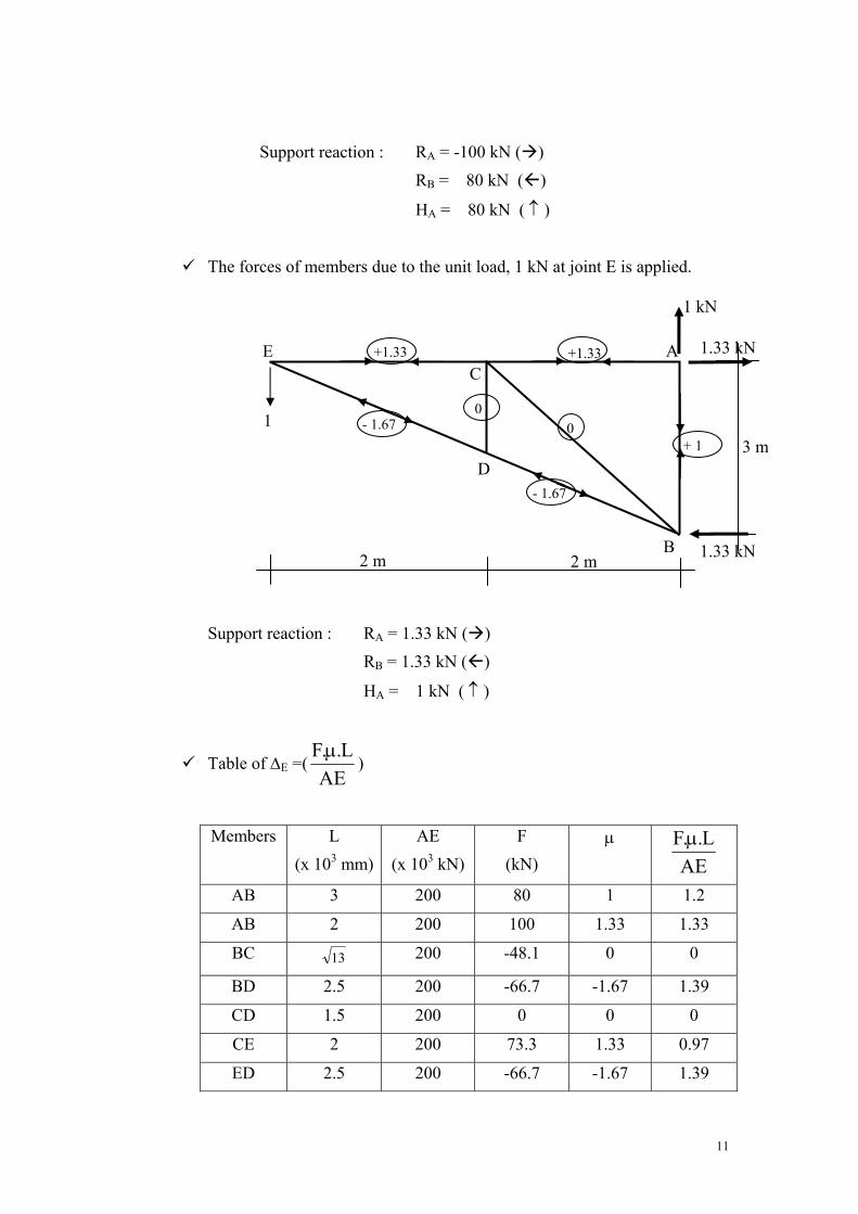
Support reaction : RA = -100 kN ( ) RB = 80 kN ( )
HA = 80 kN ( ↑ )
The forces of members due to the unit load, 1 kN at joint E is applied.
Support reaction : RA = 1.33 kN ( ) RB = 1.33 kN ( )
HA = 1 kN ( ↑ )
Table of ΔE =(AE
L..F μ)
Members L (x 103 mm)
AE (x 103 kN)
F (kN)
μ
AEL..F μ
AB 3 200 80 1 1.2
AB 2 200 100 1.33 1.33
BC 13 200 -48.1 0 0
BD 2.5 200 -66.7 -1.67 1.39
CD 1.5 200 0 0 0
CE 2 200 73.3 1.33 0.97
ED 2.5 200 -66.7 -1.67 1.39
1
E C
D
A
B 2 m 2 m
3 m
1.33 kN
1.33 kN
+1.33
- 1.67
+1.33
0
- 1.67
+ 1
1 kN
0
11

The vertical displacement at joint E;
ΔE =∑ (AE
L..F μ) = 1.2 + 1.33 + 0 + 1.39 + 0 + 0.97 + 1.39 = 6.28 mm
EXERCISE 3.2: A pin-jointed plane truss is pinned at point A and supported on a roller at point E. it carries point loads at point C and D. Using method of virtual work, determine the vertical displacement at joint C. Given the following:
Area of each member = 1500mm2
E = 200 kN/mm2
EXAMPLE 2.4 The modulus of elasticity of each member is E = 20 kN/mm2 and the cross-sectional area of each member is 1000 mm2
, except members EB and EC is 40 mm2. Determine;
a) the vertical displacement at joint C. b) the horizontal displacement at joint C.
12

20 kN
20 kN
C
D
A
B
1 m E
1
m 1 m 1 m Solution :
The forces of members due to the real load are applied. 20 kN
20 kN
C
D
A
B
E20 kN
20 kN
(0) (0)
(20) (20)
(0) (-20)
(-28.3)
13
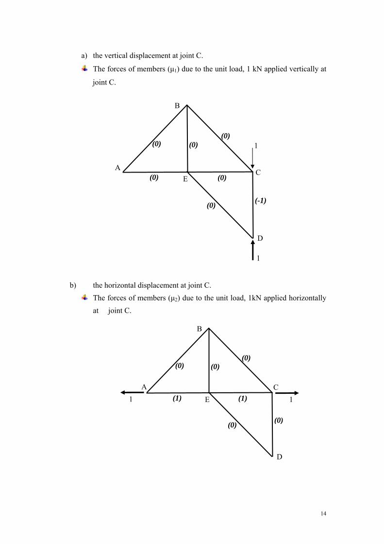
a) the vertical displacement at joint C.
The forces of members (μ1) due to the unit load, 1 kN applied vertically at
joint C.
1
C
D
A
B
E
1
(0) (0)
(0) (0)
(0) (-1)
(0)
b) the horizontal displacement at joint C.
The forces of members (μ2) due to the unit load, 1kN applied horizontally at joint C.
1 C
D
A
B
E
(0) (0)
(1) (1)
(0)
(0)
(0)
1
14

Table of ΔC = (AE
L..F μ );
Members
L (mm)
A (mm2)
F (kN)
μ1 μ2
ALF .. 1μ
ALF .. 2μ
AB 1414 1000 0 0 0 0 0
BC 1414 1000 -28.3 0 0 0 0
CD 1000 1000 -20 1 0 20 0
DE 1414 1000 0 0 0 0 0
EA 1000 1000 20 0 1 0 20
EB 1000 40 0 0 0 0 0
EC 1000 40 20 0 1 0 500
Vertical deflection at joint C = ΔCy = (AE
L..F μ ) = 20 / 20 = 1 mm (↓)
Horizontal deflection at joint C = ΔCx = (AE
L..F μ ) = 520 / 20 = 26 mm (→)
15

TUTORIAL 2 1. A statically determinate pin-jointed plane truss is pinned at A and supported on rollers at B. It carries two point loads of 50kN at joints F and G. Using Method of Virtual Work, determine the vertical displacement at joint F. Given: L = 5m for each member A1 = 2500mm2 for top and bottom chords A2 = 2000mm2 for diagonal members E = 210 kN/m2
2. For the pin-jointed cantilever truss shown in figure, all the members have an area of 625 mm2 and Young Modulus is 200GPa,
a) show that the structure is a statically determinate structure b) find all reactions on the support c) determine the vertical and horizontal deflection at point E using the
unit load method.
DE A
B
C
16

3. Figure shows a structure loaded with vertical load of 40 kN at joint C, horizontal Load of 20 kN at joint C and 30 kN at joint E. The structure is supported by a roller at joint A and pinned at joint F. (a) Determine the determinacy of the structure. (b) Calculate all Reaction Forces at each support. (c) Calculate and sketch the Internal Force due to External Force for each
element of the structure. Assume the AE value is coherent or same at all elements and the given value is AE = 80 x 103 kN. Using Method of Virtual Work, fill in the value in the table and determine the following terms, (d) Horizontal displacement of joint C if 1 Unit Load in horizontal direction is applied at the joint.
(e) Calculate and sketch the internal force due to the Unit Load at joint C.
(f) Vertical displacement of joint D if 1 Unit Load in vertical direction is
applied at the joint.
(g) Calculate and sketch the internal force due to the Unit Load at joint D.
A
B
C
D E
F
m0.3
m0.3
m0.4 m0.4
kN40 kN20
kN30
(UTHM SEM I 2007/2008 BFC 3023)
17

4. Determine the displacement at joint C of the truss shown in figure below. The modulus of elasticity of each member is 200 x 106 kN/m2 and the cross sectional area for all members is 100mm2.
5. Determine the vertical and horizontal displacement at joint C of the truss shown in figure below. The modulus of elasticity of each member is E = 200 kN/mm2 and the cross-sectional area of the diagonal member is 1000 mm2 ,another members is 600 mm2.
A
B C
D 5 m
5
m
6 kN
10 m10 m
18