Embed Size (px)
Citation preview

CHAPTER 1B
INTRODUCTION TO AUTOCAD
PDT176 COMPUTER-AIDED DRAFTING

Introduction
2

To start a new drawing
4

Selecting a Template
Workspace drop-down menu
In AutoCAD, new drawings are typically created with some
form of template.
Simple drawings can be created with the acad.dwt template.
Select template dialog box 5

EXPLORING THE DRAWING WINDOW
6

Grid Lines
Drawing Area
View Cube
User Coordinate
System UCS icon
7
INTERACTING WITH THE DRAWING
WINDOW

Page Setup Manager
8

Page Setup Manager
9

DRAWING UNITS
10
AutoCAD can work in any of five different unit systems:
scientific, decimal, engineering, architectural, or
fractional.

Precision of the units system
11
Select degree
precision
for angles here. Select two
decimal places.

TABs AND PANELS
12
The headings across the top of the screen (Home, Insert,
etc.) are called tabs, and the groupings of commands
under the tabs are called panels.
Panels Tab

EXPLORING COMMAND ENTRY METHODS
13
Line tool
Basic tooltip
Extended tooltip
1. Locate the cursor arrow on the selected tool (icon). In the example
shown, the Line command tool within the Draw panel was
selected.
2. Hold the arrow still without pressing any mouse buttons.
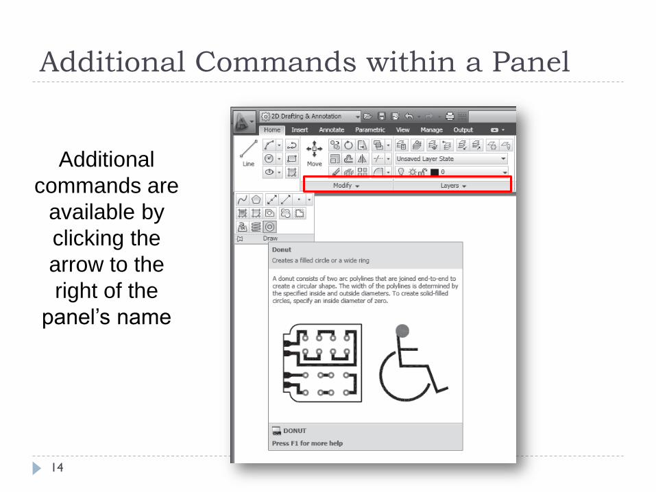
Additional Commands within a Panel
14
Additional
commands are
available by
clicking the
arrow to the
right of the
panel’s name

GRID AND SNAP
The Grid
command is used
to place a lined grid
background on the
drawing screen
The Snap command
limits the movement
of the cursor to
predefined points on
the screen
15

GRID
16
Grid : 20 Grid : 5
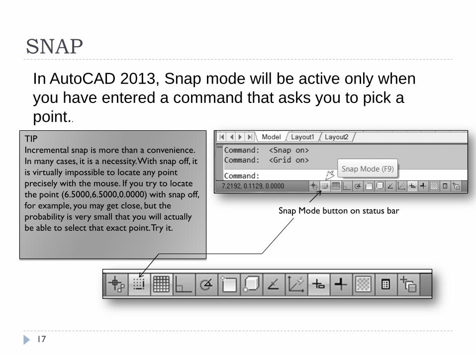
Snap Mode button on status bar
In AutoCAD 2013, Snap mode will be active only when
you have entered a command that asks you to pick a
point..
TIP
Incremental snap is more than a convenience.
In many cases, it is a necessity. With snap off, it
is virtually impossible to locate any point
precisely with the mouse. If you try to locate
the point (6.5000,6.5000,0.0000) with snap off,
for example, you may get close, but the
probability is very small that you will actually
be able to select that exact point. Try it.
SNAP
17

Cartesian and Polar Coordinate System
Cartesian coordinates - xyz (x, y, and z values separated by a
comma) you can use the coordinate display to pick a point in your
drawing while the dynamic display continues to show the polar
coordinates of the line you are drawing.
Polar Coordinates - (length<angle, z) The two dimensions in the
dynamic input display will show a visual display of polar coordinates.
Polar coordinates are given as a length and an angle relative to a
starting point.
18

Working With Coordinate Systems
Direct Distance Entry - You can also enter values directly to
the dynamic input display. For example, you can pick the first
point of a line and then show or type the direction of the line
segment you wish to draw, but instead of picking the other
endpoint you type in a value for the length of the line.
Absolute Coordinates and # - It is important to know that you
can also type the absolute coordinates (8,8) at the Specify
second point: prompt, but you must first type the number (#)
sign. The # sign specifies absolute coordinates rather than
coordinates relative to the last point.
Relative Coordinates and @ - Besides typing or picking points
on the screen, AutoCAD allows you to enter points by typing
coordinates relative to the last point selected.
19

Ortho Mode
Ortho Mode - Ortho forces the pointing device to pick
up points only along the horizontal and vertical
quadrant lines from a given starting point. With Ortho
on, you can select points at 0°, 90°, 180°, and 270°
of rotation from your starting point only
20

Polar Tracking
Polar Tracking - Polar tracking is an AutoCAD feature
that can replace Ortho mode in many instances.
With Polar Tracking on, when the rubber band crosses
a vertical or horizontal axis (i.e., when the rubber band
is at 0°, 90°, 180°, or 270°), a dotted line appears that
extends to the edge of the drawing area.
Notice that Polar Tracking and Ortho are mutually
exclusive. They cannot both be on at the same time.
When you turn Polar Tracking on, Ortho shuts off
automatically.
21

Command
Prompt
Window
INTERACTING WITH THE DRAWING
WINDOW
Typed commands and options appear here.
22
THE COMMAND LINE BOX
23
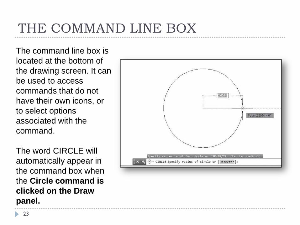
The command line box is
located at the bottom of
the drawing screen. It can
be used to access
commands that do not
have their own icons, or
to select options
associated with the
command.
The word CIRCLE will
automatically appear in
the command box when
the Circle command is
clicked on the Draw
panel.

The new command line has the quality of transparency,
most noticeable when it is moved into the drawing area.
Because it is transparent, it interferes only minimally with
objects behind it.
You will also notice that as commands are typed, the last few
command line prompts and responses (by default, the last three) are
displayed above the Line.
EXPLORING COMMAND ENTRY METHODS
24

(Infer Constraints, Snap Mode, Grid Display, Ortho
Mode, Polar Tracking, Object Snap, 3D Object Snap,
Object Snap Tracking, Dynamic UCS, Dynamic Input,
Lineweight, Transparency, Quick Properties, and
Selection Cycling).
INTERACTING WITH THE DRAWING
WINDOW
Below the command window
is the status bar, with the
coordinate display on the
left.
To the right of the coordinate
display are mode buttons.
These are switches for
turning on and off some
extremely important features
of the drawing window.
25

EXPLORING COMMAND ENTRY METHODS
Many of the most often used commands, such as LINE,
ERASE, and CIRCLE, have aliases.
List of possibilities
26

DYNAMIC INPUT DISPLAY (F12)
Dynamic input display is a very powerful feature that in many ways duplicates the function of the coordinate display.
However, this display is easier to track because it follows your cursor. Also, there are times when it can be used effectively in conjunction with the coordinate display.
27

DYNAMIC INPUT DISPLAY
28
With the display off, the
dynamic input numbers
on your screen
disappear.

FUNCTION KEYS
29
F1: HELP
F2: COMMAND WINDOW ON/OFF
F3: OSNAP ON/OFF
F4: 3DOSNAP ON/OFF
F5: ISOPLANE LEFT/RIGHT/TOP
F6: DYNAMIC UCS ON/OFF (In 3D modeling)
F7: GRID ON/OFF
FUNCTION KEYS
30
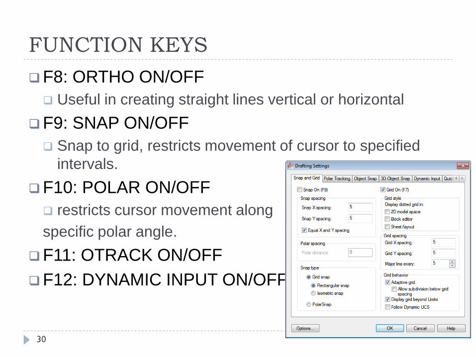
F8: ORTHO ON/OFF
Useful in creating straight lines vertical or horizontal
F9: SNAP ON/OFF
Snap to grid, restricts movement of cursor to specified
intervals.
F10: POLAR ON/OFF
restricts cursor movement along
specific polar angle.
F11: OTRACK ON/OFF
F12: DYNAMIC INPUT ON/OFF