Embed Size (px)
Citation preview

Chapter 16 PLC Function Applications|MS3
16-1
Chapter 16 PLC Function Applications
16-1 PLC Summary
16-2 Notes Before Using a PLC
16-3 Turn on
16-4 Basic Principles of PLC Ladder Diagrams
16-5 Various PLC Device Functions
16-6 Introduction to the Command Window
16-7 Error Display and Handling
16-8 Explanation of PLC Speed Mode Control
16-9 Count Function Using Pulse Input

Chapter 16 PLC Function Applications|MS3
16-2
16-1 PLC Summary 16-1-1 Introduction
The commands provided by the MS3’s built-in PLC functions, including the ladder diagram editing
tool WPLSoft, as well as the use of basic commands and application commands, follow the operating
methods of Delta’s PLC DVP series.
16-1-2 WPLSoft ladder diagram editing tool
WPLSoft is Delta's software program for the DVP and MS3 programmable controllers in Windows
operating system environment. In addition to general PLC program design and general Windows
editing functions (such as cut, paste, copy, and multiple windows), WPLSoft also provides many
features such as Chinese/English annotation editing, registry editing, settings, file reading, saving,
and contact graphic monitoring and settings.
The following table lists the basic requirements for installing the WPLSoft editing software:
Item System requirements
Operating system Windows○,R XP / Vista / 7 (32-bit / 64-bit) / 8 / 10 (64-bit)
CPU At least Pentium 90
Memory At least 16 MB (we recommend at least 32 MB)
Hard drive Hard drive capacity: at least 100 MB of free space
One optical drive (to install this software)
Display Resolution: 640×480, at least 16 colors; it is recommended that the screen
area be set at 800×600 pixels.
Mouse Ordinary mouse or Windows-compatible pointing device
Printer Printer with Windows driver software
RS-485 port Must have at least an RS-485 port to link to the PLC

Chapter 16 PLC Function Applications|MS3
16-3
16-2 Notes Before Using a PLC 1. The MS3 provides two communication serial ports that you can use to download programs to
the PLC (see figure below).
2. Channel 1 communication format is the same as channel 2.
3. Channel 2 has a preset communication format of 7, N, 2, 9600; you can change to ASCII in
Pr.09-01 (transmission speed) and Pr.09-04 (communication protocol).
4. The PLC preset is node 2; you can change the PLC node in Pr.09-35 (PLC address), but this
address may not be the same as the drive’s address setting in Pr.09-00 (communication
address).
SG+ - SG
SGND
USB
RS-485
8 1
Channel 1
Channel 2RS-485
MS300Pin 1: ReservedP in 2: ReservedP in 3: _CAN GNDPin 4: -SGP in 5: +SGPin 6: ReservedGNDPin 7: _CAN GND
5. The host controller can simultaneously access data from the drive and the internal PLC, using
the identifier for the node. For instance, if the drive node is 1 and the internal PLC node is 2,
then the host controller command depends on the node address
� 01 (node) 03 (read) 0400 (address) 0001 (1 data item), indicating that it must read the data
in drive Pr.04-00.
� 02 (node) 03 (read) 0400 (address) 0001 (1 data item), indicating that it must read the data
in internal PLC X0.
6. The PLC program is disabled when uploading/downloading programs.
7. Note that when using WPR commands to write parameters, you may modify values up to a
maximum of 106 times; otherwise, after which a memory write error occurs. The number of
modifications depends on whether the parameter value has changed. If you do not change the
value, it does not change the number of modifications; however, if the entered value is different
from before, the number of modifications increases by one.
8. When you set Pr.00-04 to 28, the displayed value is the value of PLC register D1043, as shown

Chapter 16 PLC Function Applications|MS3
16-4
below).
Digital Keypad VERSI-KP-LCD (optional)
Can display 0–65535
H 0.00HzA 0.00HzC _ _ _ _ _
9. In the PLC Run and PLC Stop mode, you cannot set Pr.00-02 to the values 9 or 10, and cannot
be reset to the default value.
10. You can reset the PLC to the default value when you set Pr.00-02 to 6.
11. The corresponding MI function is disabled when the PLC writes to input contact X.
12. When the PLC controls the drive operation, the control commands are entirely controlled by the
PLC and are not affected by the setting for Pr.00-21.
13. When the PLC controls the drive’s Frequency commands (FREQ commands), the Frequency
commands are entirely controlled by the PLC, and are not affected by the setting for Pr.00-20 or
the HAND ON/OFF configuration.
14. When the PLC controls the drive operation, if the keypad STOP setting is valid, this triggers
an FStP error and causes the drive to stop.

Chapter 16 PLC Function Applications|MS3
16-5
16-3 Turn on
16-3-1 Connect the Drive to the PC
You start operating the PLC functions with the following four steps:
After pressing the MENU key and choosing 4: PLC on the VERSI-KP-LCD digital keypad (optional),
press the ENTER key (see figure below).
PLC1.Disable2.PLC Run3.PLC Stop
2
1. Wiring: Connect the drive’s RJ45 communications interface to a PC through the RS-485 cable.
2. PLC function usage
Digital keypad VERSI-KP-LCD
(optional)
PLC1.Disable2.PLC Run3.PLC Stop
PLC functions are as shown in the figure on the left; select
item 2. PLC Run to enable the PLC functions.
1: No function (Disable)
2: Enable PLC (PLC Run)
3: Stop PLC functions (PLC Stop)

Chapter 16 PLC Function Applications|MS3
16-6
Digital keypad (VERSI-KP-LED)
Select PLC1 to enter PLC mode setting.
PLC 0: Do not implement PLC functions
PLC 1: Initiate PLC Run
PLC 2: Initiate PLC Stop
� The MS3 automatically switches to PLC mode when the external multifunctional input
terminals (MI1–MI7) are in PLC Mode selection bit 0 (51) or PLC Mode selection bit1 (52),
and the terminal contact is closed or open. In this case, keypad switching is ineffective. The
corresponding actions are listed in the following table.
PLC mode PLC Mode selection
bit1 (52) PLC Mode selection
bit0 (51) Using VERSI-KP-LCD (optional)
Using VERSI-KP-LED
Disable PLC 0 OFF OFF PLC Run PLC 1 OFF ON PLC Stop PLC 2 ON OFF
Maintain previous state Maintain previous state ON ON
Using the MS3 digital keypad to implement the PLC functions
� When the PLC screen switches to the PLC1 screen, this triggers one PLC action, and
you control the PLC program start/stop by communications with WPLSoft.
� When the PLC screen switches to the PLC2 screen, this triggers one PLC stop, and
you control the PLC program start/stop by communications with WPLSoft.
� The external terminal control method is the same as shown in the table above.
NOTE � When the input/output terminals (MI1–MI7) are included in the PLC program, these input/output
terminals are used only by the PLC. For example, when the PLC program controls Y0 during PLC
operation (PLC1 or PLC2), the corresponding output terminal relay (RA/RB/RC) operates according
to the program. At this time, the multifunctional input/output terminal setting has no effect. Because
these terminal functions are already being used by the PLC, you can determine the DI / DO / AO in
use by the PLC by looking at Pr.02-52, 02-53, and 03-30.
� When the PLC’s procedures use special register D1040, the corresponding AO contact AFM1 is
occupied.
� Pr.03-30 monitors the state of action of the PLC function analog output terminals; bit 1 corresponds
to the AFM1 action state.

Chapter 16 PLC Function Applications|MS3
16-7
16-3-2 I/O device explanation
Input devices: Serial No. X0 X1 X2 X3 X4 X5 X6 X7 X10 X11 X12 X13 X14 X15 X16 X17
1 MI1 MI2 MI3 MI4 MI5 MI6 MI7
Output devices: Serial No.
Y0 Y1 Y2 Y3 Y4 Y5 Y6 Y7 Y10 Y11 Y12 Y13 Y14 Y15 Y16 Y17
1 RY MO1 MO2
16-3-3 Installing WPLSoft
See Delta’s website where you can download the WPLSoft editing software:
http://www.delta.com.tw/product/em/download/download_main.asp?act=3&pid=3&cid=1&tpid=3
16-3-4 Writing programs in WPLSoft
After you install WPLSoft, the WPLSoft program is located in the folder “C:\Program Files\Delta
Industrial Automation\WPLSoft x.xx.” You can run the editing software by double-clicking the WPL
icon.
The WPL editing window appears after three seconds (see figure below). When running WPLSoft for
the first time, before you create a new project file, the menu bar shows only File, View,
Communications, Options, and Help menus.

Chapter 16 PLC Function Applications|MS3
16-8
The next time you run WPLSoft, the program opens the last project file you edited. The following
picture describes the main parts of the WPLSoft editing window.
To open a new project file, on the Toolbar, click the New button (or press Ctrl+N)

Chapter 16 PLC Function Applications|MS3
16-9
Alternatively, on the File menu, click New (Ctrl+N).
This displays the Select a PLC Model dialog box where you can enter the Program Title, File Name,
and select the device and communication settings.
In the Communication Setting dialog box, define the communication settings and then click OK.
6
2
502

Chapter 16 PLC Function Applications|MS3
16-10
You can then begin editing the program. There are two program editing methods: you can edit in the
command mode, or edit in the ladder diagram mode.
In the ladder diagram mode, you can use the buttons on the function icon row on the toolbar.
Basic Operation
Example: Create the ladder diagram in the following picture.

Chapter 16 PLC Function Applications|MS3
16-11
Use the following steps to create the ladder diagram. These steps show you how to use both the
mouse and the keyboard (F1–F12) to add functions.
1. The following picture shows the WPLSoft program after you create a new project file.
2. Add an always-open switch. On the toolbar click the always-open switch button or press F1.
3. In the Input Device Instruction dialog box, select the device name (such as M), device number
(such as 10) and enter comments (such as auxiliary coil). Click OK when finished.
4. Add an output coil. Click the output coil button or press F7.
In the Input Device Instruction dialog box, select the device name (such as Y), the device
number (such as 0) and enter comments (such as output coil).Click OK when finished.

Chapter 16 PLC Function Applications|MS3
16-12
5. On the toolbar, click the Application Command button or press F6.
In the Application Instructions dialog box, in Instruction Type drop-down list, select All
Application Instructions. In the Application Instruction drop-down list, select END, or use the
keyboard to type “END”, and then click OK.
6. Compile the program. On the toolbar, click the Compile button to compile the edited ladder
diagram into a command program. After compiling, the number of rungs appear on the left side of
the busbar.

Chapter 16 PLC Function Applications|MS3
16-13
16-3-5 Program download
After you compile your program, download it to the device. Click the Download button . WPLSoft
downloads the program to the online PLC in the communication format that you specified for the
communication settings.
16-3-6 Program monitoring
After you download the program, confirm that the PLC is in Run mode. On the Communication menu,
click Online Mode , and then click Start Ladder Diagram Control (see the following picture).
This allows you to supervise and operate the ladder diagram while online.

Chapter 16 PLC Function Applications|MS3
16-14
16-4 Basic Principles of PLC Ladder Diagrams
16-4-1 Schematic diagram for PLC ladder diagram program scanning
Output results are
calculated on the basis
of the ladder diagram
configuration
(internal devices have
real-time output
before results are sent to
an external output point)
Repeated
program scans
16-4-2 Introduction to ladder diagrams
Ladder diagrams use a graphic language widely applied in automatic controls. They employ
common electrical control circuit symbols. After you use a ladder diagram editor to create a ladder
diagram program, the PLC program design is complete. Using a graphic format to control processes
is very intuitive and is readily accepted by personnel who are familiar with electrical control circuit
technology. Many of the basic symbols and actions in a ladder diagram mimic common electrical
devices in conventional automatic control power distribution panels, such as buttons, switches,
relays, timers, and counters.
Internal PLC devices: The types and quantities of internal PLC devices vary in different brands of
products. Although these internal devices use the same names as the conventional electrical control
circuit elements (such as relays, coils, and contacts), a PLC does not actually contain these physical
devices, and they instead correspond to basic elements in the PLC's internal memory (bits). For
instance, if a bit is 1, this may indicate that a coil is electrified; and if that bit is 0, it indicates that the
coil is not electrified. You can use a N.O. contact (Normally Open, or contact A) to directly read the
value of the corresponding bit, and use a NC contact (Normally Closed, or contact B) to get the
inverse of the bit’s value. Multiple relays occupy multiple bits, and eight bits comprise one byte. Two
bytes comprise one word, and two words comprise a double word. When multiple relays are
processing at the same time (as in addition/subtraction or displacement), it can use a byte, a word, or
a double word. Furthermore, a PLC contains two types of internal devices: a timer and a counter. It
not only has a coil, but can count time and numerical values. Because of this, when it is necessary to
process numerical values, these values are usually in the form of bytes, words, or double words
(internally in the PLC).

Chapter 16 PLC Function Applications|MS3
16-15
The various internal devices in a PLC use a certain amount of memory in the PLC’s storage area. When you use these devices, the content of the corresponding storage area is read in the form of bits, bytes, or words.
The following table describes the internal devices in a PLC
Device Type Description of Function
Input Relay
An input relay constitutes the basic unit of storage in a PLC's internal memory, and corresponds to an external input point. It serves as a terminal connecting with an external input switch and receiving external input signals. It is driven by external input signals, to which it assigns values of 0 or 1. A program design method cannot change the input relay status, and therefore cannot rewrite the corresponding basic units of an input relay. You cannot use WPLSoft to manually perform ON/OFF actions. You can use a relay's contacts (contacts A and B) an unlimited number of times in a program. An input relay with no input signal must be left idle and cannot be used for some other purpose. � Input devices are indicated by X0, X1, X7, X10, X11, and so on. These devices are
indicated with the symbol X, and a device's order is indicated with an octal number. Input point numbers are indicated in the main PLC and in expansion devices.
Output Relay
An output relay constitutes the basic unit of storage in a PLC's internal memory, and corresponds to an external output point. It connects with an external load. It can be driven by an input relay contact, a contact on another internal device, or its own contacts. It uses one N.O. contact to connect with external loads or other contacts, and like the input contacts, you can use the output relay’s contacts an unlimited number of times in a program. An output relay with no input signal is idle, but can be used by an internal relay if needed. � Output devices are indicated by Y0, Y1, Y7, Y10, Y11, and so on. These devices are
indicated with the symbol Y, and a device's order is indicated with an octal number. Output point numbers are indicated in the main PLC and in expansion devices.
Internal Relay
Internal relays have no direct connection with the outside. These relays are auxiliary relays inside a PLC. Their function is the same as that of an auxiliary (central) relay in an electrical control circuit: Each auxiliary relay corresponds to a basic unit of internal storage; they can be driven by input relay contacts, output relay contacts, and the contacts of other internal devices. You can use an internal auxiliary relay's contacts an unlimited number of times in a program. Internal relays have no outputs to the outside, and their status must output through an output point. � Internal relay devices are indicated by: M0, M1–M799, and so on. These devices are
indicated with the symbol M, and the device’s order is indicated with a decimal number.
Counter
Counters perform counting operations. The setting value for a counter (such as the number of pulses to be counted) must be assigned when a counter is used. A counter contains a coil, contact, and a counting storage device. When the coil goes from OFF � ON, this indicates that the counter receives an input pulse, and adds one to its count. There are 16 bits available in the counter. � Counter device are indicated by: C0, C1–C79, and so on. These devices are
indicated by the symbol C, and the device’s order is indicated with a decimal number.
Timer
Timers perform timing for operations. The timer contains a coil, contact, and a time value register. When the coil is electrified, and the setting value for the timer is reached, the contact is actuated (contact A closes, contact B opens), and the timer's fixed value is given by the setting value. A timer has a regulated clock cycle (timing units: 100 ms). As soon as power to the coil is cut off, the contact is no longer be actuated (contact A opens, contact B closes), and the original timing value returns to zero. � Timer devices are indicated by: T0, T1–T159, and so on. These devices are indicated
by the symbol T, and the device’s order is indicated with a decimal number.
Data register
Data registers are used exclusively to store data and various parameters. When you use a PLC is to perform various types of sequence control, set time values, and count value controls, the PLC performs data processing and numerical operations and stores the operands, parameters, and results in data registers. Each data register contains 16 bits of binary data (one word). Two data registers with adjacent numbers can process double words.

Chapter 16 PLC Function Applications|MS3
16-16
Device Type Description of Function
� Data register devices are indicated by: D0, D1– D399, and so on. These devices are indicated by the symbol D, and the device’s order is indicated with a decimal number.
Ladder diagram images and explanations
Ladder diagram structures Explanation of commands Command Using Device
N.O. switch, contact A LD X, Y, M, T, C
N.C. switch, contact B LDI X, Y, M, T, C
Series N.O. AND X, Y, M, T, C
Series N.C. ANI X, Y, M, T, C
Parallel N.O. OR X, Y, M, T, C
Parallel N.C. ORI X, Y, M, T, C
Rising edge-triggered switch LDP X, Y, M, T, C
Falling edge-triggered switch LDF X, Y, M, T, C
Rising edge-triggered series ANDP X, Y, M, T, C
Falling edge-triggered series ANDF X, Y, M, T, C
Rising edge-triggered parallel ORP X, Y, M, T, C
Falling edge-triggered parallel ORF X, Y, M, T, C
Block series ANB N/A
Block parallel ORB N/A
Multiple outputs
MPS MRD MPP
N/A
Coil driven output
commands OUT Y, M
Some basic commands, application commands.
Some basic commands, application commands.
Inverted logic INV N/A
Chapter 16 PLC Function Applications|MS3
16-17
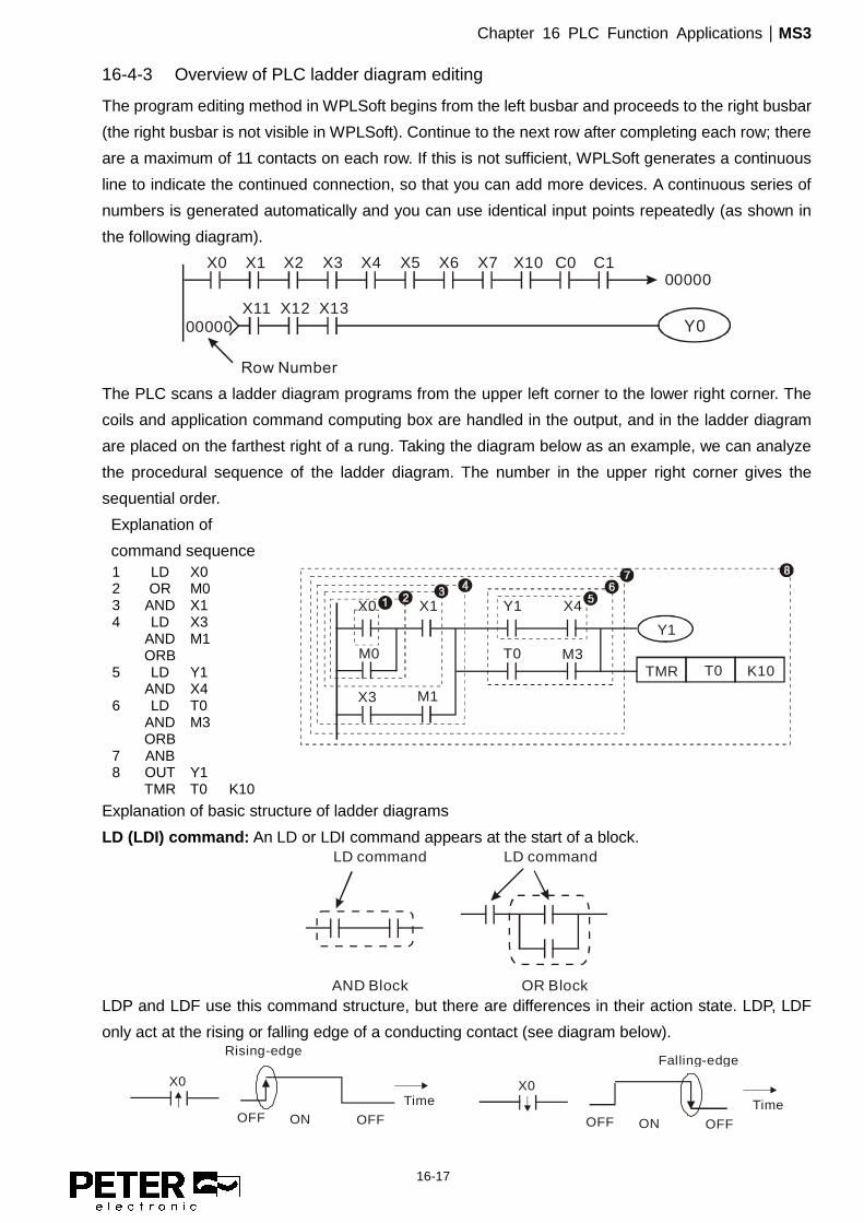
16-4-3 Overview of PLC ladder diagram editing
The program editing method in WPLSoft begins from the left busbar and proceeds to the right busbar
(the right busbar is not visible in WPLSoft). Continue to the next row after completing each row; there
are a maximum of 11 contacts on each row. If this is not sufficient, WPLSoft generates a continuous
line to indicate the continued connection, so that you can add more devices. A continuous series of
numbers is generated automatically and you can use identical input points repeatedly (as shown in
the following diagram).
X0 X1 X2 X3 X4 X5
Y0X11 X12 X13
X6 X7 X10 C0 C100000
00000
Row Number
The PLC scans a ladder diagram programs from the upper left corner to the lower right corner. The
coils and application command computing box are handled in the output, and in the ladder diagram
are placed on the farthest right of a rung. Taking the diagram below as an example, we can analyze
the procedural sequence of the ladder diagram. The number in the upper right corner gives the
sequential order.
Explanation of
command sequence
X0 X1 Y1 X4
M0
X3 M1
T0 M3
Y1
TMR T0 K10
1 LD X0 2 OR M0 3 AND X1 4 LD X3 AND M1 ORB 5 LD Y1 AND X4 6 LD T0 AND M3 ORB 7 ANB 8 OUT Y1 TMR T0 K10
Explanation of basic structure of ladder diagrams
LD (LDI) command: An LD or LDI command appears at the start of a block.
AND Block OR Block
LD command LD command
LDP and LDF use this command structure, but there are differences in their action state. LDP, LDF
only act at the rising or falling edge of a conducting contact (see diagram below).
X0
OFF ON OFF
Time
Falling-edge
X0
OFF ON OFF
Time
Rising-edge

Chapter 16 PLC Function Applications|MS3
16-18
AND (ANI) command: a series configuration in which a single device is connected with one device
or a block. AND command AND command
ANDP, ANDF use this structure, but their action occurs at the rising and falling edge of a conducting
contact.
OR (ORI) command: a single device is connected with one device or a block.
OR command OR command OR command ORP, ORF use this structure, but their action occurs at the rising and falling edge a conduction
contact.
ANB command: a configuration in which one block is in series with one device or block. ANB command
ORB command: a configuration in which one block is in parallel with one device or block.
ORB command
In the case of ANB and ORB operations that connect a number of blocks, they should be combined
to form a block or network from the top down or from left to right.
MPS, MRD, MPP commands: branching point memory for multiple outputs that enable multiple
different outputs. The MPS command begins at a branching point, which refers to the intersection of
horizontal and vertical lines. Control relies on the contact status along a single vertical line to
determine whether the next contact can give a memory command. While each contact is basically
able to give memory commands, in view of convenience and the PLC's capacity restrictions, this can
be omitted from some places when editing a ladder diagram. You can use the structure of the ladder
diagram to judge what kinds of contact memory commands are used.
MPS is indicated by use of the ┬ symbol. You can use this command consecutively up to eight times.
The MRD command is read from branching point memory; because logic states along any one
vertical line must be the same, in order to continue analysis of other parts of the ladder diagram, the

Chapter 16 PLC Function Applications|MS3
16-19
original contact status must be read. MRD is indicated by the ├ symbol.
The MPP command is read from the starting state of the uppermost branching point, and it is read
from the stack (pop operation); because it is the final command along a vertical line, it indicates that
the state of the vertical line can be concluded. MPP is indicated by the └ symbol.
Although there should basically be no errors when using the foregoing analytical approach, the
compiling program may sometimes omit identical state output, as shown in the following diagram.
( )
( )
( )
( )
( )
( )
( )
MPS
MPP
MRD
16-4-4 Common basic program design examples
Start, stop, and protection circuits
Some applications may require a brief close or brief break using a button to start and stop equipment.
A protective circuit must therefore be designed to maintain continued operation in these situations.
This protective circuit may employ one of the following methods.
Example 1: Priority stop protective circuit
When the start N.O. contact X1=ON, and the stop N.C. contact X2=OFF, Y1=ON. If X2
switches to ON, coil Y1 is no longer electrified, and this is therefore referred to as priority
stop. Y1 X2
X1
START
STOP
Y1
Example 2: Priority start protective circuit
When the start N.O. contact X1=ON, and the stop N.C. contact X2=OFF, Y1=ON, and
coil Y1 is electrified and protected. If X2 switches to ON, coil Y1 still protects the contact
and continues to be electrified, and this is therefore referred to as priority start.
Y1
X2X1
START STOP
Y1
Example 3: Setting (SET) and reset (RST) command protective circuit
The following diagram shows a protective circuit composed of RST and SET commands.
A priority stop occurs when you place the RST command after the SET command.
Because the PLC executes programs from the top down, at the end of the program, the
state of Y1 indicates whether coil Y1 is electrified. When X1 and X2 both actuate, Y1

Chapter 16 PLC Function Applications|MS3
16-20
loses power, and this is therefore referred to as priority stop.
A priority start occurs when you place the SET command after the RST command. When
X1 and X2 both actuate, Y1 electrifies, and this is therefore referred to as priority start.
SET Y1
RST Y1
X1
X2
Top priority of stop
SET
Y1RST
Y1
X2
X1
Top priority of start
Commonly used control circuits Example 4: Conditional control
X1 and X3 respectively start and stop Y1; and X2 and X4 respectively start and stop Y2.
All have protective circuits. Because Y1's N.O. contact is in series with Y2's circuit, it
becomes an AND condition for the actuation of Y2. The action of Y1 is therefore a
condition for the action of Y2, and Y1 must actuate before Y2 can actuate.
X1 X3
Y1
Y1
X2 X4
Y2
Y2Y1
X1
X3
X2
X4
Y1
Y2
Example 5: Interlocking control
The diagram below shows an interlocking control circuit. Depending on which of the start
contacts X1 or X2 becomes valid first, the corresponding output Y1 or Y2 actuates, and
when one actuates, the other does not actuate. Y1 and Y2 cannot actuate at the same
time (interlocking effect). Even if both X1 and X2 are valid at the same time, because the
ladder diagram program is scanned from the top down, it is impossible for Y1 and Y2 to
actuate at same time. This ladder diagram assigns priority only to Y1.
Chapter 16 PLC Function Applications|MS3
16-21
X1 X3
Y1
Y1
X2 X4
Y2
Y2Y1
X1
X3
X2
X4
Y1
Y2
Y2
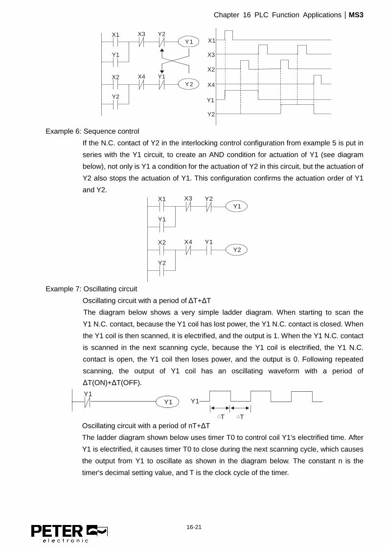
Example 6: Sequence control
If the N.C. contact of Y2 in the interlocking control configuration from example 5 is put in
series with the Y1 circuit, to create an AND condition for actuation of Y1 (see diagram
below), not only is Y1 a condition for the actuation of Y2 in this circuit, but the actuation of
Y2 also stops the actuation of Y1. This configuration confirms the actuation order of Y1
and Y2. X1 X3
Y1
Y1
X2 X4
Y2
Y2Y1
Y2
Example 7: Oscillating circuit
Oscillating circuit with a period of ΔT+ΔT
The diagram below shows a very simple ladder diagram. When starting to scan the
Y1 N.C. contact, because the Y1 coil has lost power, the Y1 N.C. contact is closed. When
the Y1 coil is then scanned, it is electrified, and the output is 1. When the Y1 N.C. contact
is scanned in the next scanning cycle, because the Y1 coil is electrified, the Y1 N.C.
contact is open, the Y1 coil then loses power, and the output is 0. Following repeated
scanning, the output of Y1 coil has an oscillating waveform with a period of
ΔT(ON)+ΔT(OFF).
Y1Y1 Y1
T T Oscillating circuit with a period of nT+ΔT
The ladder diagram shown below uses timer T0 to control coil Y1's electrified time. After
Y1 is electrified, it causes timer T0 to close during the next scanning cycle, which causes
the output from Y1 to oscillate as shown in the diagram below. The constant n is the
timer's decimal setting value, and T is the clock cycle of the timer.

Chapter 16 PLC Function Applications|MS3
16-22
T0Y1
Y1
nT T
TMR T0 Kn X0Y1X0
Example 8: Flashing circuit
The following diagram shows an oscillating circuit of a type commonly used to cause an
indicator to flash or a buzzer to buzz. It uses two timers to control the ON and OFF time of
Y1 coil. Here constants n1 and n2 are the setting values of timers T1 and T2, and T is the
clock cycle of the timer.
T1
Y1
Y1
n1*T
TMR T1 Kn1 X0T2X0
TMR T2 Kn2
T1X0
n2*T
Example 9: Triggering circuit
In the diagram below, a rising edge in input X0 causes coil M0 to generate a single pulse
for ΔT (length of one scanning cycle), and coil Y1 is electrified during this scanning cycle.
Coil M0 loses power during the next scanning cycle, and N.C. contact M0 and N.C.
contact Y1 are both closed. This causes coil Y1 to stay in an electrified state until there is
another rising edge in input X0. This again causes the electrification of coil M0 and the
start of another scanning cycle, while also causing coil Y1 to lose power, and so on. You
can see the sequence of these actions in the diagram below. This type of circuit is
commonly used to enable one input to perform two alternating actions. You can see from
the time sequence in the diagram below that when input X0 is a square wave signal with
a period of T, the output of coil Y1 is a square wave signal with a period of 2T.
X0
M0
X0
Y1M0
M0
Y1Y1M0
Y1
T
Example 10: Delay circuit
When input X0 is ON, because the corresponding NC contact is OFF, the timer T10 is in
a no power state, and output coil Y1 is electrified. T10 receives power and begins to
counter the time only after input X0 is OFF, and output coil Y1 is delayed for 100
seconds (K1000*0.1 sec. =100 sec.) before losing power. You can see the sequence of
actions in the diagram below.

Chapter 16 PLC Function Applications|MS3
16-23
Example 11: The open/close delay circuit is composed of two timers; output Y4 has a delay no matter
input X0 is ON or OFF.
Example 12: Extended timing circuit
In the circuit in the ladder diagram on the left, the total delay time from the moment input
X0 closes to the time output Y1 is electrified is (n1+n2)*T, where T is the clock cycle.
The timers are T11 and T12, and the clock cycle is T.
X0
Y1
TMR T12 Kn2
X0
T11
TMR T11 Kn1
T12
Y1
T11
T12
n1*T
n2*T
(n1+n2)*T

Chapter 16 PLC Function Applications|MS3
16-24
16-5 Various PLC Device Functions Item Specifications Notes
Algorithmic control method
The program is stored internally, alternating back-and-forth scanning method.
Input/output control method
When the scan starts again after ending (after execution to the END command), the input/output is immediately refreshed.
Algorithmic processing speed
Basic commands (several μs); Application command (1 to several tens of μs)
Programming language
Command + ladder diagram
Program capacity 2000 steps
Input/output terminal Input (X): 10, output (Y): 4
This is the number for MS3 input/output contacts; other devices have different correspondences.
Type Device Item Range Function
Relay bit form
X External input relay X0–X17, 16 points, octal number Total
32 points
Corresponds to external input point
Y External output relay Y0–Y17, 16 points, octal number
Corresponds to external output point
M Auxiliary
Relay
General Use M0–M799, 800 points Total 1080 points
Contact can switch ON/OFF within the program
Special purpose
M1000–M1279, 280 points
T Timer 100 ms timer T0–T79, 80 points Total 80
points
Timers referred to by the TMR command; T contact with the same number switches ON when the time is reached.
C Counter 16-bit counter, general use
C0–C39, 40 points Total 40
points
Counter referred to by the CNT command; C contact with the same number switches ON when the count is reached.
Register w
ord data
T Current timer value T0–T79, 80 points The contact switches ON when the time is reached.
C Current counter value C0–C39, 16-bit counter 40 points The counter contact switches ON when the count is reached.
D Data
Register
Used to maintain power OFF
D0–D9, 10 points Total 420
points
Used as data storage memory area
Special purpose
D10–D199, 190 points D1000–D1219, 220 points
Constant K Decimal
Single-byte Setting Range: K-32,768–K32,767 Double-byte Setting Range: K-2,147,483,648–K2,147,483,647
H Hexadecimal Single-byte Setting Range: H0000–HFFFF Double-byte Setting Range: H00000000–HFFFFFFFF
Serial communication port (program write/read)
RS-485/keypad port
Input/output Built-in three analog inputs and two analog outputs
High-speed counting Built-in a (MI7) 32-bit high-speed counter
Function expansion module Optional
Accessories --
Communication Expansion Module
Optional Accessories
EMC-COP01, (CANopen)

Chapter 16 PLC Function Applications|MS3
16-25
16-5-1 Introduction to device functions
Input/output contact functions
Input contact X has this function: input contact X is connected with an input device, and reads input
signals entering the PLC. There are no restrictions on the number of times that the input contact A or
B appear in the program. The ON/OFF state of input contact X changes as the input device switches
between ON and OFF; you cannot use a peripheral device (WPLSoft) to force contact X ON or OFF.
Output contact Y functions The output contact Y sends an ON/OFF signal to drive the load connected to output contact Y. There
are two types of output contacts: relays and transistors. There are no restrictions on the number of
times that contact A or B of an output contact Y appear in a program, but it is recommended that you
use the number of output coil Y only once in a program; otherwise the output state when the PLC
performs program scanning is determined by the program's final output Y circuit.
Numerical value, constant [K] / [H]
Constant
Single-byte K Decimal
K-32,768–K32,767
Double-byte K-2,147,483,648–K2,147,483,647
Single-byte H Hexadecimal
H0000–HFFFF
Double-byte H00000000–HFFFFFFFF
The PLC uses five types of numerical values to implement calculations based on its control tasks; the
following topics explain the use and function of the different numerical values.
Binary Number, BIN
The PLC's numerical operations and memory employ binary numbers. The following table explains
terms related to binary numbers. bit Bits are the fundamental units of binary values, and have a state of either 1 or 0.
Nibble Comprised of a series of 4 bits (such as b3–b0); can be used to express a one-nibble decimal number 0–9 or hexadecimal number: 0–F.
Byte Comprised of a series of two nibbles (i.e. 8 bits, b7–b0); can express a hexadecimal number: 00-FF.
Word Comprised of a series of two bytes (i.e. 16 bits, b15–b0); can express a hexadecimal number with four nibbles: 0000–FFFF.
Double Word Comprised of a series of two words (i.e. 32 bits, b31–b0); can express a hexadecimal number with eight nibbles: 00000000–FFFFFFFF
The following diagram shows the relationship between bits, digits, nibbles, words, and double words
in a binary system (see figure below).

Chapter 16 PLC Function Applications|MS3
16-26
NB0NB1NB2NB3NB4NB5NB6NB7
BY3 BY2 BY1 BY0
W1
DW
W0
Double Word
Word
Byte
Nibble
Bit
Octal Number, OCT
The external input and output terminals of a DVP-PLC are numbered using octal numbers.
Example: External input: X0–X7, X10–X17…(Device number table);
External output: Y0–Y7, Y10–Y17…(Device number table)
Decimal Number, DEC
A PLC uses decimal numbers for the following purposes:
� The setting values of timer T or counter C, such as TMR C0 K50 (K constant).
� The numbers of devices including M, T, C, or D, such as M10 or T30 (device number).
� An operand in an application command, such as MOV K123 D0 (K constant).
Binary Coded Decimal, BCD
Uses one nibble or four bits to express the data in a decimal number; a series of 16 bits can therefore
express a decimal number with four nibbles. These are used to read the input value of a rotating
numerical switch to input or output a numerical value to a seven-segment display drive.
Hexadecimal Number, HEX
A PLC uses hexadecimal numbers as operands in application commands, such as MOV H1A2B D0
(H constant).
Constant K
PLC’s usually prefixed decimal numbers with K, such as K100. This indicates that it is a decimal
number with a numeric value of 100.
Exceptions: You can combine K with a bit device X, Y, M, or S to produce data in the form of a nibble,
byte, word, or double word, such as in the case of K2Y10 or K4M100. Here K1
represents a 4-bit combination, and K2–K4 represent 8-, 12-, and 16-bit combinations.
Constant H
PLC’s usually prefixed hexadecimal numbers with H, such as in the case of H100. This indicates a
hexadecimal number with a numeric value of 100.
Functions of auxiliary relays
Like an output relay Y, an auxiliary relay M has an output coil and contacts A and B, and you can use

Chapter 16 PLC Function Applications|MS3
16-27
the output relay contacts any number of times in a program. You can use an auxiliary relay M to
configure the control circuit, but cannot use the auxiliary relay to directly drive an external load. There
are two types of auxiliary relays:
Ordinary auxiliary relays: ordinary auxiliary relays all revert to the OFF state when a power outage
occurs while the PLC is running, and remains in the OFF state when power
is restored.
Special purpose auxiliary relays: each special purpose auxiliary relay has its own specific use. Do not
use any undefined special purpose auxiliary relays. Timer functions
Timers use 100 ms as their timing unit. When the timing method is an upper time limit, and the
current timer value = setting value, the timer output coil is energized. Timer setting values use
decimal K values; you can also use the data register D as a setting value.
Actual timer setting time = timing units * set value
Counter features
Item 16-bit counter Type General Type
CT Direction: Up Setting 0–32,767
Designation of set value Constant K or data register D Change in current value When the count reaches the setting value, it stops counting.
Output contact When the count reaches the setting value, the contact switches ON and stays ON.
Reset The current value reverts to 0 when an RST command is executed, and the contact reverts to OFF.
Contact actuation All are actuated after the end of scanning.
Counter functions
When a counter's counting pulse input signal switches from OFF to ON, if the counter's current value
is equal to the setting value, the output coil switches ON. The setting value can be either a decimal K
or a data register D.
16-bit counter:
� 16-bit counter setting range: K0–K32,767. When K0 and K1 are identical, the output contact is
immediately ON during the first count.
� The current counter value is cleared from an ordinary counter when power to the PLC turns
OFF.
� If you use the MOV command or WPLSoft to transmit a value greater than the setting value to
the C0 current value register, when the next X1 switches from OFF to ON, the C0 counter
contact changes to ON, and the current value changes to the setting value.
� You can set a counter's setting value directly using a constant K, or indirectly using the value in
register D (not including special data registers D1000–D1199 or D2000–D2799).
� If the setting value is a constant K, the value must be a positive number. If the setting value is
from data register D, the value can be either a positive or negative number. If using a data
register, and the current value is 32,767, incrementing the count causes the count value to roll

Chapter 16 PLC Function Applications|MS3
16-28
over to -32,768 as the count continues to accumulate.
Example
LD X0 X0
Y0
CNT C0 K5X1
RST C0
C0
RST C0
LD X1
CNT C0 K5
LD C0
OUT Y0
1. When X0 = ON and the RST command is
executed, the current value of C0 reverts
to 0, and the output contact reverts to OFF.
2. When X1 switches from OFF to ON, the
current value of the counter is
incremented by one (add one).
3. When the count in C0 reaches the set
value K5, the contact C0 switches to ON,
and the current value of C0 = setting value
= K5. Afterwards, additional changes in X1
do not affect the count value, and C0
remains at K5.
X0
X1
01
23
45
0
Contacts Y0, C0
C0 present value
settings

Chapter 16 PLC Function Applications|MS3
16-29
16-5-2 Introduction to special relay functions (special M)
R/W column: RO means read only; RW means read and write.
Special M Function Descriptions R/W *
M1000 Monitors N.O. contact (contact A). N.O. while RUN, contact A. This contact is ON while in the RUN state. RO
M1001 Monitors N.C. contact (contact B). NC while RUN, contact B. This contact is OFF while in the RUN state. RO
M1002 Initiates a forward pulse (the instant RUN is ON). Initial pulse, contact A. Produces a forward pulse when RUN begins; pulse width = scan cycle. RO
M1003 Initiates a reverse pulse (the instant RUN is OFF). Initial pulse, contact A. Produces a reverse pulse when RUN ends; pulse width = scan cycle. RO
M1004 Reserved RO M1005 Drive malfunction instructions RO M1006 Drive has no output RO M1007 Drive direction FWD(0) / REV(1) RO M1008
– M1010
-- --
M1011 10 ms clock pulse, 5 ms ON / 5 ms OFF. RO M1012 100 ms clock pulse, 50 ms ON / 50 ms OFF. RO M1013 1 sec. clock pulse, 0.5 s ON / 0.5 s OFF RO M1014 1 min. clock pulse, 30 s ON / 30 s OFF RO M1015 Frequency reached (when used with M1025) RO M1016 Parameter read/write error RO M1017 Parameter write successful RO M1018 -- -- M1019 -- -- M1020 Zero flag RO M1021 Borrow flag RO M1022 Carry flag RO M1023 Divisor is 0 RO M1024 -- --
M1025 Drive frequency = set frequency (ON) Drive frequency = 0 (OFF) RW
M1026 Drive operating direction FWD (OFF) / REV (ON) RW M1027 Drive Reset RW M1028 -- -- M1029 -- -- M1030 -- -- M1031 -- -- M1032 -- -- M1033 -- -- M1034 -- -- M1035 -- -- M1036 -- -- M1037 -- -- M1038 MI7 count begins RW M1039 Reset MI7 count value RW M1040 Hardware power (Servo On) RW M1041 -- -- M1042 Quick Stop RW M1043 -- -- M1044 Pause (Halt) RW M1045 -- --

Chapter 16 PLC Function Applications|MS3
16-30
Special M Function Descriptions R/W *
– M1047 M1048 -- -- M1049 -- -- M1050 -- -- M1051 -- -- M1052 Lock frequency (lock, frequency locked at the current operating frequency) RW M1053 -- -- M1054 -- -- M1055 -- -- M1056 Hardware already has power (Servo On Ready) RO M1057 -- -- M1058 On Quick Stopping RO
16-5-3 Introduction to special register functions (special D)
Special D Function Descriptions R/W *
D1000 -- -- D1001 Device system program version RO D1002 Program capacity RO D1003 Total program memory content RO D1004
– D1009
-- --
D1010 Current scan time (units: 0.1 ms) RO D1011 Minimum scan time (units: 0.1 ms) RO D1012 Maximum scan time (units: 0.1 ms) RO D1013
– D1017
-- --
D1018 Current integral value RO D1019 Force setting for PID I integral RW D1020 Output frequency (0.00–599.00 Hz) RO D1021 Output current (####.#A) RO D1022 -- --
D1023
Communication expansion card number 0: No expansion card 1: DeviceNet Slave 2: PROFIBUS-DP Slave 3: CANopen Slave 4: Modbus-TCP Slave 5: EtherNet/IP Slave
RO
D1024 –
D1026 -- --
D1027 PID calculation frequency command (frequency command after PID calculation) RO D1028 AVI value (0.00–100.00%) RO D1029 ACI value (0.00–100.00%) RO D1030 -- -- D1031
– D1034
-- --
D1035 VR value (0.0–100.00%) RO D1036 Servo error bit RO
Chapter 16 PLC Function Applications|MS3
16-31
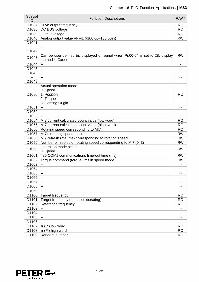
Special D Function Descriptions R/W *
D1037 Drive output frequency RO D1038 DC BUS voltage RO D1039 Output voltage RO D1040 Analog output value AFM1 (-100.00–100.00%) RW D1041
– D1042
-- --
D1043 Can be user-defined (is displayed on panel when Pr.00-04 is set to 28; display method is Cxxx)
RW
D1044 -- - D1045 -- -- D1046
– D1049
-- --
D1050
Actual operation mode 0: Speed 1: Position 2: Torque 3: Homing Origin
RO
D1051 -- -- D1052 -- -- D1053 -- -- D1054 MI7 current calculated count value (low word) RO D1055 MI7 current calculated count value (high word) RO D1056 Rotating speed corresponding to MI7 RO D1057 MI7's rotating speed ratio RW D1058 MI7 refresh rate (ms) corresponding to rotating speed RW D1059 Number of nibbles of rotating speed corresponding to MI7 (0–3) RW
D1060 Operation mode setting 0: Speed RW
D1061 485 COM1 communications time-out time (ms) RW D1062 Torque command (torque limit in speed mode) RW D1063 -- -- D1064 -- -- D1065 -- -- D1066 -- -- D1067 -- -- D1068 -- -- D1069 -- -- D1100 Target frequency RO D1101 Target frequency (must be operating) RO D1102 Reference frequency RO D1103 -- -- D1104 -- -- D1105 -- -- D1106 -- -- D1107 π (Pi) low word RO D1108 π (Pi) high word RO D1109 Random number RO

Chapter 16 PLC Function Applications|MS3
16-32
16-5-4 PLC Communication address
Device Range Type Address (Hex) X 00–17 (Octal) bit 0400–040FF Y 00–17 (Octal) bit 0500–050F T 00–79 bit/word 0600–064F M 000–799 bit 0800–0B1F M 1000–1279 bit 0BE8–0CFF C 0–39 bit/word 0E00–0E27 D 00–199 word 1000–10C7 D 1000–1219 word 13E8–14C3
Command codes that can be used Function Code Function Descriptions Function target
H1 Coil status read Y, M, T, C
H2 Input status read X, Y, M, T, C
H3 Read single unit of data T, C, D
H5 Force single coil status change Y, M, T, C
H6 Write single unit of data T, C, D
HF Force multiple coil status change Y, M, T, C
H10 Write multiple units of data T, C, D
NOTE When PLC functions have been activated, the MS3 can match the PLC and drive parameters; this method uses different
addresses for drives (default station number is 1, PLC sets station number as 2).

Chapter 16 PLC Function Applications|MS3
16-33
16-6 Introduction to the Command Window
16-6-1 Overview of basic commands
� Ordinary commands Command
code Function OPERAND Execution speed (µs)
LD Load contact A X, Y, M, T, C 0.8 LDI Load contact B X, Y, M, T, C 0.8 AND Connect contact A in series X, Y, M, T, C 0.8 ANI Connect contact B in series X, Y, M, T, C 0.8 OR Connect contact A in parallel X, Y, M, T, C 0.8 ORI Connect contact B in parallel X, Y, M, T, C 0.8 ANB Series circuit block N/A 0.3 ORB Parallel circuit block N/A 0.3 MPS Save to stack N/A 0.3 MRD Stack read (pointer does not change) N/A 0.3 MPP Read stack N/A 0.3
� Output command Command
code Function OPERAND Execution speed (µs)
OUT Drive coil Y, M 1 SET Action continues (ON) Y, M 1 RST Clear contact or register Y, M, T, C, D 1.2
� Timer, counter Command
code Function OPERAND Execution speed (µs)
TMR 16-bit timer T-K or T-D commands 1.1 CNT 16-bit counter C-K or C-D (16-bit) 0.5
� Main control command Command
code Function OPERAND Execution speed (µs)
MC Common series contact connection N0–N7 0.4 MCR Common series contact release N0–N7 0.4
� Contact rising edge/falling edge detection command Command
code Function OPERAND Execution speed (µs)
LDP Start of rising edge detection action X, Y, M, T, C 1.1 LDF Start of falling edge detection action X, Y, M, T, C 1.1
ANDP Rising edge detection series connection X, Y, M, T, C 1.1 ANDF Falling edge detection series connection X, Y, M, T, C 1.1 ORP Rising edge detection parallel connection X, Y, M, T, C 1.1 ORF Falling edge detection parallel connection X, Y, M, T, C 1.1
� Upper/lower differential output commands Command
code Function OPERAND Execution speed (µs)
PLS Upper differential output Y, M 1.2 PLF Lower differential output Y, M 1.2
� Stop command

Chapter 16 PLC Function Applications|MS3
16-34
Command code Function OPERAND
Execution speed (µs)
END Program conclusion N/A 0.2
� Other commands Command
code Function OPERAND Execution speed (µs)
NOP No action N/A 0.2 INV Inverse of operation results N/A 0.2 P Index P 0.3

Chapter 16 PLC Function Applications|MS3
16-35
16-6-2 Detailed explanation of basic commands
Command Function LD Load contact A
Operand X0–X17 Y0–Y17 M0–M799 T0–159 C0–C79 D0–D399
� � � � � -
Use the LD command for contact A starting at the left busbar or contact A starting at a contact circuit block; its function is to save current content and save the acquired contact status in the cumulative register.
Ladder diagram:
X0 X1Y1
Command code: Description:
LD X0 Load Contact A of X0
AND X1 Create a series connection to contact A of X1
OUT Y1 Drive Y1 coil
Command Function LDI Load contact B
Operand X0–X17 Y0–Y17 M0–M799 T0–159 C0–C79 D0–D399
� � � � � -
Use the LDI command for contact B starting at the left busbar or contact B starting at a contact circuit block; its function is to save current content and save the acquired contact status in the cumulative register.
Ladder diagram:
X0 X1Y1
Command code: Description:
LDI X0 Load Contact B of X0
AND X1 Create a series connection to contact A of X1
OUT Y1 Drive Y1 coil
Command Function AND Connect contact A in series
Operand X0–X17 Y0–Y17 M0–M799 T0–159 C0–C79 D0–D399
� � � � � -
Use the AND command to create a series connection to contact A; its function is to first read the current status of the designated series contact and the logical operation results before contact in order to perform "AND" operation; saves the results in the cumulative register.
Ladder diagram:
X1 X0Y1
Command code: Description: LDI X1 Load Contact B of X1
AND X0 Create a series connection to contact A of X0
OUT Y1 Drive Y1 coil

Chapter 16 PLC Function Applications|MS3
16-36
Command Function ANI Connect contact B in series
Operand X0–X17 Y0–Y17 M0–M799 T0–159 C0–C79 D0–D399
� � � � � -
Use the ANI command to create a series connection to contact B; its function is to first read the current status of the designated series contact and the logical operation results before contact in order to perform "AND" operation; saves the results in the cumulative register.
Ladder diagram:
X0X1Y1
Command code: Description:
LD X1 Load Contact A of X1
ANI X0 Create a series connection to contact B of X0
OUT Y1 Drive Y1 coil
Command Function OR Connect contact A in parallel
Operand X0–X17 Y0–Y17 M0–M799 T0–159 C0–C79 D0–D399
� � � � � -
Use the OR command to establish a parallel connection to contact A; its function is to first read the current status of the designated series contact and the logical operation results before contact in order to perform "OR" operation; saves the results in cumulative register.
Ladder diagram:
X0
X1
Y1
Command code: Description:
LD X0 Load Contact A of X0
OR X1 Create a series connection to contact A of X1
OUT Y1 Drive Y1 coil
Command Function ORI Connect contact B in parallel
Operand X0–X17 Y0–Y17 M0–M799 T0–159 C0–C79 D0–D399
� � � � � -
Use the ORI command to establish a parallel connection to contact B; its function is to first read the current status of the designated series contact and the logical operation results before contact in order to perform "OR" operation; saves the results in cumulative register.
Ladder diagram:
X0
X1
Y1
Command code: Description:
LD X0 Load Contact A of X0
ORI X1 Create a series connection to contact B of X1
OUT Y1 Drive Y1 coil

Chapter 16 PLC Function Applications|MS3
16-37
Command Function ANB Series circuit block
Operand N/A
ANB performs an "AND" operation on the previously saved logic results and the current cumulative register content.
Ladder diagram:
X1
X3
Y1X0
X2
ANB
Block A Block B
Command code: Description: LD X0 Load Contact A of X0
ORI X2 Establish a parallel connection to contact B of X2
LDI X1 Load Contact B of X1
OR X3 Establish a parallel connection to contact A of X3
ANB Series circuit block OUT Y1 Drive Y1 coil
Command Function ORB Parallel circuit block
Operand N/A
ORB performs an "OR" operation on the previously saved logic results and the current cumulative register content.
Ladder diagram:
X1
X3
Y1X0
X2ORB
Block A
Block B
Command code: Description: LD X0 Load Contact A of X0
ANI X1 Establish a parallel connection to contact B of X1
LDI X2 Load Contact B of X2
AND X3 Establish a parallel connection to contact A of X3
ORB Parallel circuit block OUT Y1 Drive Y1 coil
Command Function MPS Save to stack
Operand N/A
Saves the current content of the cumulative register to the stack (add one to the stack pointer).
Command Function MRD Read stack (pointer does not change)
Operand N/A
Reads the stack content and saves to the cumulative register (the stack pointer does not change).

Chapter 16 PLC Function Applications|MS3
16-38
Command Function MPP Read stack
Operand N/A
Retrieves the result of the previously saved logical operation from the stack, and saves to the cumulative register. (subtract one from stack pointer)
Ladder diagram:
X0Y1
X1
M0X2
Y2
ENDMPP
MRD
MPS
Command code: Description: LD X0 Load Contact A of X0
MPS Save to the stack
AND X1 Create a series connection to contact A of X1
OUT Y1 Drive Y1 coil
MRD Read the stack (pointer does not change)
AND X2 Create a series connection to contact A of X2
OUT M0 Drive M0 coil MPP Read stack OUT Y2 Drive Y2 coil END Program conclusion
Command Function OUT Drive coil
Operand X0–X17 Y0–Y17 M0–M799 T0–159 C0–C79 D0–D399
- � � - - -
Outputs the result of the logical operation before the OUT command to the designated element. Coil contact action:
Result: Out command
Coil Access Point:
Contact A (N.O.) Contact B (N.C.) FALSE OFF Not conducting Conducting TRUE ON Conducting Not conducting
Ladder diagram:
X0 X1Y1
Command code: Description: LD X0 Load Contact B of X0
AND X1 Establish a parallel connection to contact A of X1
OUT Y1 Drive Y1 coil
Command Function SET Action continues (ON)
Operand X0–X17 Y0–Y17 M0–M799 T0–159 C0–C79 D0–D399
- � � - - -
Sets the designated element to ON, and maintains it in an ON state, regardless of whether the SET command is still driven. Use the RST command to set the element as OFF.
Ladder diagram:
Y0X0Y1SET
Command code: Description: LD X0 Load Contact A of X0
AN Y0 Establish a parallel connection to contact B of Y0

Chapter 16 PLC Function Applications|MS3
16-39
SET Y1 Action continues (ON)
Command Function RST Clear contact or register
Operand X0–X17 Y0–Y17 M0–M799 T0–159 C0–C79 D0–D399
- � � � � �
Resets the designated element as described. Element Mode
Y, M Both coil and contact are set as OFF.
T, C Sets the current timing or count value to 0, and both the coil and contact are set to OFF.
D Sets the content value to 0. If the RST command is not executed, the status of the designated element remains unchanged.
Ladder diagram:
X0Y5RST
Command code: Description: LD X0 Load Contact A of X0
RST Y5 Clear the contact or register
Command Function TMR 16-bit timer
Operand T-K T0–T159, K0–K32,767 T-D T0–T159, D0–D399
Electrifies the designated timer coil, and the timer begins timing. The contact's action is as follows when the timing value reaches the designated setting value (timing value ≥ setting value):
N.O. (Normally Open) contact Closed N.C. (Normally Closed) contact Open
If the RST command is not executed, the status of the designated element remains unchanged.
Ladder diagram:
X0T5TMR K1000
Command code: Description: LD X0 Load Contact A of X0
TMR T5 K1000
T5 timer Set value as K1000
Command Function
CNT 16-bit counter
Operand C-K C0–C79, K0–K32,767
C-D C0–C79, D0–D399
When you execute the CNT command from OFF to ON, switch the designated counter coil from no power to electrified and add one to the counter's count value. When the count reaches the designated value (count value = setting value), the contact has the following action:
N.O. (Normally Open) contact Closed
N.C. (Normally Closed) contact Open After reaching the count value, the contact and count value both remain unchanged even with continued count pulse input. Use the RST command to restart or clear the count.
Ladder diagram: X0
C2CNT K100
Command code: Description: LD X0 Load Contact A of X0
CNT C2 K100 C2 counter Set value as K100

Chapter 16 PLC Function Applications|MS3
16-40
Command Function MC/MCR Connect/release a common series contact
Operand N0–N7
MC is the main control initiation command, and any command between MC and MCR is executed normally. When the MC command is OFF, any command between MC and MCR acts as follows:
Determination of commands Description
Ordinary timer The timing value reverts to 0, the coil loses power, and the contact does not operate.
Counter The coil loses power, and the count value and contact stay in their current state.
Coil driven by OUT command None receives power. Elements driven by SET, RST
commands They remain in their current state.
Application commands None are actuated. MCR is the main control stop command, and is placed at the end of the main control program. There may not be any contact command prior to the MCR command. The MC-MCR main control program commands support a nested program structure with a maximum of only eight levels; use in the order N0–N7. Refer to the following program example:
Ladder diagram: X0
MC N0
X1Y0
X2MC N1
X3Y1
MCR N1
MCR N0
X10MC N0
X11Y10
MCR N0
Command code:
Description:
LD X0 Load Contact A of X0
MC N0 Connection of N0 common series contact
LD X1 Load Contact A of X1 OUT Y0 Drive Y0 coil
: LD X2 Load Contact A of X2
MC N1 Connection of N1 common series contact
LD X3 Load Contact A of X3 OUT Y1 Drive Y1 coil
:
MCR N1 Release N1 common series contact
:
MCR N0 Release N0 common series contact
: LD X10 Load Contact A of X10
MC N0 Connection of N0 common series contact
LD X11 Load Contact A of X11 OUT Y10 Drive Y10 coil
:
MCR N0 Release N0 common series contact

Chapter 16 PLC Function Applications|MS3
16-41
Command Function LDP Start of rising edge detection action
Operand X0–X17 Y0–Y17 M0–M799 T0–159 C0–C79 D0–D399
� � � � � -
The LDP command has the same use as LD, but its action is different. Its function is to save the current content while also saving the detected state of the rising edge of the contact to the cumulative register.
Ladder diagram: X1
Y1X0
Command code:
Description:
LDP X0 Start of X0 rising edge detection action
AND X1 Create a series connection to contact A of X1
OUT Y1 Drive Y1 coil
Command Function LDF Start of falling edge detection action
Operand X0–X17 Y0–Y17 M0–M799 T0–159 C0–C79 D0–D399
� � � � � -
The LDF command has the same use as LD, but its action is different. Its function is to save the current content while also saving the detected state of the falling edge of the contact to the cumulative register.
Ladder diagram:
X1Y1
X0
Command code: Description:
LDF X0 Start of X0 falling edge detection action
AND X1 Create a series connection to contact A of X1
OUT Y1 Drive Y1 coil
Command Function ANDP Rising edge detection series connection
Operand X0–X17 Y0–Y17 M0–M799 T0–159 C0–C79 D0–D399
� � � � � -
Use the ANDP command for a contact rising edge detection series connection.
Ladder diagram:
X1Y1
X0
Command code: Description: LD X0 Load Contact A of X0
ANDP X1 X1 Rising edge detection series connection
OUT Y1 Drive Y1 coil

Chapter 16 PLC Function Applications|MS3
16-42
Command Function ANDF Falling edge detection series connection
Operand X0–X17 Y0–Y17 M0–M799 T0–159 C0–C79 D0–D399
� � � � � -
Use the ANDF command for a contact falling edge detection series connection.
Ladder diagram:
X1Y1
X0
Command code: Description: LD X0 Load Contact A of X0
ANDF X1 X1 Falling edge detection series connection
OUT Y1 Drive Y1 coil
Command Function ORP Rising edge detection parallel connection
Operand X0–X17 Y0–Y17 M0–M799 T0–159 C0–C79 D0–D399
� � � � � -
Use the ORP command for a contact rising edge detection parallel connection.
Ladder diagram: X0
X1Y1
Command code: Description:
LD X0 Load Contact A of X0
ORP X1 X1 Rising edge detection parallel connection
OUT Y1 Drive Y1 coil
Command Function ORF Falling edge detection parallel connection
Operand X0–X17 Y0–Y17 M0–M799 T0–159 C0–C79 D0–D399
� � � � � -
Use the ORF command for a contact falling edge detection parallel connection.
Ladder diagram: X0
X1
Y1
Command code: Description:
LD X0 Load Contact A of X0
ORF X1 X1 Falling edge detection parallel connection
OUT Y1 Drive Y1 coil
Chapter 16 PLC Function Applications|MS3
16-43
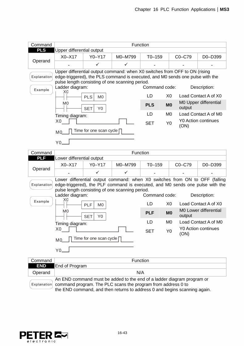
Command Function PLS Upper differential output
Operand X0–X17 Y0–Y17 M0–M799 T0–159 C0–C79 D0–D399
- � � - - -
Upper differential output command: when X0 switches from OFF to ON (rising edge-triggered), the PLS command is executed, and M0 sends one pulse with the pulse length consisting of one scanning period.
Ladder diagram:
X0M0PLS
M0Y0SET
Timing diagram: X0
M0
Y0
Time for one scan cycle
Command code: Description:
LD X0 Load Contact A of X0
PLS M0 M0 Upper differential output
LD M0 Load Contact A of M0
SET Y0 Y0 Action continues (ON)
Command Function PLF Lower differential output
Operand X0–X17 Y0–Y17 M0–M799 T0–159 C0–C79 D0–D399
- � � - - -
Lower differential output command: when X0 switches from ON to OFF (falling edge-triggered), the PLF command is executed, and M0 sends one pulse with the pulse length consisting of one scanning period.
Ladder diagram: X0
M0PLF
M0Y0SET
Timing diagram: X0
M0
Y0
Time for one scan cycle
Command code: Description:
LD X0 Load Contact A of X0
PLF M0 M0 Lower differential output
LD M0 Load Contact A of M0
SET Y0 Y0 Action continues (ON)
Command Function END End of Program
Operand N/A
An END command must be added to the end of a ladder diagram program or command program. The PLC scans the program from address 0 to the END command, and then returns to address 0 and begins scanning again.

Chapter 16 PLC Function Applications|MS3
16-44
Command Function NOP No action
Operand N/A
The NOP command does not perform any operation in the program. Because execution of this command retains the original logical operation results, you can use it in the following situation: use the NOP command instead of a command that is deleted without changing the program length.
Ladder diagram:
Command code: Description:
LD X0 Load Contact B of X0
NOP No action
OUT Y1 Drive Y1 coil
Command Function INV Inverse of operation results
Operand N/A
Saves the result of the logic inversion operation prior to the INV command in the cumulative register.
Ladder diagram:
X0Y1
Command code: Description:
LD X0 Load Contact A of X0
INV Inverse of operation results
OUT Y1 Drive Y1 coil
Command Function P Pointer
Operand P0–P255
Use pointer P as the target in a subprogram call (command API 01 CALL). Using P does not require starting from zero, but the number cannot be used repeatedly; otherwise, an unpredictable error occurs.
Ladder diagram:
X0
Y1
CALL P10
X1P10
Command code: Description:
LD X0 Load Contact A of X0 CALL P10 Call command CALL to
P10
:
P10 Pointer P10
LD X1 Load Contact A of X1
OUT Y1 Drive Y1 coil

Chapter 16 PLC Function Applications|MS3
16-45
16-6-3 Overview of application commands
Classification API Command code P
command Function STEPS
16 bit 32 bit 16 bit 32 bit
Circuit control 01 CALL - � Call subprogram 3 - 2 SRET - - End a subprogram 1 - 06 FEND - - End a main program 1 -
Send comparison
10 CMP DCMP � Compare set output 7 13 11 ZCP DZCP � Range comparison 9 17 12 MOV DMOV � Move data 5 9 15 BMOV – � Send all 7 –
Four logical operations
20 ADD DADD � BIN addition 7 13 21 SUB DSUB � BIN subtraction 7 13 22 MUL DMUL � BIN multiplication 7 13 23 DIV DDIV � BIN division 7 13 24 INC DINC � BIN add one 3 5 25 DEC DDEC � BIN subtract one 3 5
Rotational displacement
30 ROR DROR � Right rotation 5 – 31 ROL DROL � Left rotation 5 –
Data Process 40 ZRST – � Clear range 5 -
49 – DFLT � Convert BIN whole number to binary floating point number - 9
Communication 150 MODRW – � Modbus read/write 7 –
Floating point operation
110 – DECMP � Compare binary floating point numbers
– 13
111 – DEZCP � Compare binary floating point number range
– 17
116 – DRAD � Convert angle to diameter – 9 117 – DDEG � Convert diameter to angle – 9
120 – DEADD � Add binary floating point numbers
– 13
121 – DESUB � Subtract binary floating point numbers
– 13
122 – DEMUL � Multiply binary floating point numbers
– 13
123 – DEDIV � Divide binary floating point numbers
– 13
124 – DEXP � Find exponent of a binary floating point number – 9
125 – DLN � Find natural logarithm of a binary floating point number
– 9
127 – DESQR � Find the square root of binary floating point number
– 9
129 – DINT � Convert binary floating point number to BIN whole number
– 9
130 – DSIN � Find the sine of a binary floating point number
– 9
131 – DCOS � Find the cosine of a binary floating point number
– 9
132 – DTAN � Find the tangent of a binary floating point number
– 9
133 – DASIN � Find the arcsine of a binary floating point number
– 9
134 – DACOS � Find the arccosine of a binary floating point number
– 9
135 – DATAN � Find the arctangent of a binary floating point number
– 9
Floating point operation
136 – DSINH � Find the hyperbolic sine of a binary floating point number
– 9

Chapter 16 PLC Function Applications|MS3
16-46
Classification API Command code P
command Function STEPS
16 bit 32 bit 16 bit 32 bit
137 – DCOSH � Find the hyperbolic cosine of a binary floating point number
– 9
138 – DTANH � Find the hyperbolic tangent of a binary floating point number
– 9
Calendar
160 TCMP – � Compare calendar data 11 – 161 TZCP – � Compare calendar data range 9 – 162 TADD – � Calendar data addition 7 – 163 TSUB – � Calendar data subtraction 7 – 166 TRD – � Calendar data read 3 –
GRAY code 170 GRY DGRY � Convert BIN to GRAY code 5 9 171 GBIN DGBIN � Convert GRAY code to BIN 5 9
Contact form logical
operation
215 LD& DLD& - Contact form logical operation LD#
5 9
216 LD| DLD| - Contact form logical operation LD#
5 9
217 LD^ DLD^ - Contact form logical operation LD#
5 9
218 AND& DAND& - Contact form logical operation AND#
5 9
219 ANDl DANDl - Contact form logical operation AND#
5 9
220 AND^ DAND^ - Contact form logical operation AND#
5 9
221 OR& DOR& - Contact form logical operation OR#
5 9
222 OR| DOR| - Contact form logical operation OR#
5 9
223 OR^ DOR^ - Contact form logical operation OR#
5 9
Contact form comparison command
224 LD= DLD= - Contact form compare LD* 5 9
225 LD> DLD> - Contact form compare LD* 5 9
226 LD< DLD< - Contact form compare LD* 5 9
228 LD<> DLD<> - Contact form compare LD* 5 9
229 LD<= DLD<= - Contact form compare LD* 5 9
230 LD>= DLD>= - Contact form compare LD* 5 9
232 AND= DAND= - Contact form compare AND* 5 9
233 AND> DAND> - Contact form compare AND* 5 9
234 AND< DAND< - Contact form compare AND* 5 9
236 AND<> DAND<> - Contact form compare AND* 5 9
237 AND<= DAND<= - Contact form compare AND* 5 9
238 AND>= DAND>= - Contact form compare AND* 5 9
240 OR= DOR= - Contact form compare OR* 5 9
241 OR> DOR> - Contact form compare OR* 5 9
242 OR< DOR< - Contact form compare OR* 5 9
244 OR<> DOR<> - Contact form compare OR* 5 9
245 OR<= DOR<= - Contact form compare OR* 5 9
246 OR>= DOR>= - Contact form compare OR* 5 9

Chapter 16 PLC Function Applications|MS3
16-47
Classification API Command code P
command Function STEPS
16 bit 32 bit 16 bit 32 bit
Floating point contact form
275 - FLD= - Floating point number contact form compare LD*
- 9
276 - FLD> - Floating point number contact form compare LD*
- 9
277 - FLD< - Floating point number contact form compare LD*
- 9
Comparison command
278 - FLD<> - Floating point number contact form compare LD*
- 9
279 - FLD<= - Floating point number contact form compare LD*
- 9
280 - FLD>= - Floating point number contact form compare LD*
- 9
281 - FAND= - Floating point number contact form compare AND*
- 9
282 - FAND> - Floating point number contact form compare AND* - 9
283 - FAND< - Floating point number contact form compare AND*
- 9
284 - FAND<> - Floating point number contact form compare AND*
- 9
285 - FAND<= - Floating point number contact form compare AND*
- 9
286 - FAND>= - Floating point number contact form compare AND*
- 9
287 - FOR= - Floating point number contact form compare OR*
- 9
288 - FOR> - Floating point number contact form compare OR*
- 9
289 - FOR< - Floating point number contact form compare OR*
- 9
290 - FOR<> - Floating point number contact form compare OR*
- 9
291 - FOR<= - Floating point number contact form compare OR*
- 9
292 - FOR>= - Floating point number contact form compare OR*
- 9
Drive special command
139 RPR – � Read servo parameter 5 – 140 WPR – � Write servo parameter 5 – 141 FPID – � Drive PID control mode 9 – 142 FREQ – � Drive torque control mode 7 – 262 – DPOS � Set target - 5 263 TORQ – � Set target torque 5 -
261 CANRX – � Read CANopen slave station
data 9 -
264 CANTX – � Write CANopen slave station
data 9 -
265 CANFLS – � Refresh special
D corresponding to CANopen 3 -
320 ICOMR DICOMR � Internal communications read 9 17 321 ICOMW DICOMW � Internal communications write 9 17

Chapter 16 PLC Function Applications|MS3
16-48
16-6-4 Detailed explanation of application commands
API CALL
S Call a subprogram 01 P
bit device Word device 16-bit command (3 STEP) CALL Continuous
execution type CALLP Pulse
execution type 32-bit command
- - - - Flag signal: none
X Y M K H KnX KnY KnM T C D
Notes on operand usage: The S operand can designate P. MS3 series device: The S operand can designate P0-P63.
� S: Call subprogram pointer.
� Write the subprogram after the FEND command.
� The subprogram must end after the SRET command.
� Refer to the FEND command explanation and sample content for detailed command functions.
API SRET
- End a subprogram 02 P
bit device Word device 16-bit command (1 STEP)
FEND Continuous execution type - -
32-bit command
- - - - Flag signal: none
X Y M K H KnX KnY KnM T C D
Notes on operand usage: No operand A contact-driven command is not needed.
� A contact-driven command is not needed. Automatically returns next
command after CALL command.
� Indicates end of subprogram. After end of subprogram, SRET returns to main program, and executes next command after the original call subprogram CALL command.
� Refer to the FEND command explanation and sample content for detailed command functions.

Chapter 16 PLC Function Applications|MS3
16-49
API
FEND
- End of a main program 06
bit device Word device 16-bit command (1 STEP)
FEND Continuous execution type - -
32-bit command
- - - - Flag signal: none
X Y M K H KnX KnY KnM T C D
Notes on operand usage: No operand A contact-driven command is not needed.
� This command indicates the end of the main program. It is the same as
the END command when the PLC executes this command. � The CALL command program must be written after the FEND command,
and the SRET command is added to the end of the subprogram. � When using the FEND command, an END command is also needed.
However, the END command must be placed at the end, after the main program and subprogram.

Chapter 16 PLC Function Applications|MS3
16-50
API
CMP
S1 S2 D Compare set output 10 D P
bit device Word device 16-bit command (7 STEP) CMP Continuous
execution type CMPP Pulse
execution type 32-bit command (13 STEP)
DCMP Continuous execution type
DCMPP Pulse execution type
Flag signal: none
X Y M K H KnX KnY KnM T C D
S1 * * * * * * * *
S2 * * * * * * * *
D * *
Notes on operand usage: The operand D occupies three consecutive points
� S1 : Compare value 1. S2 : Compare value 2. D : Results of comparison.
� Compares the size of the content of operand S1 and S2 ; stores the results
of the comparison in D . � Size comparison is performed algebraically. All data is compared in the form of
numerical binary values. Because this is a 16-bit command, when b15 is 1, this indicates a negative number.
� When the designated device is Y0, it automatically occupies Y0, Y1 and Y2. � When X10=ON, the CMP command executes, and Y0, Y1 or Y2 is ON. When
X10=OFF, the CMP command does not execute, and the state of Y0, Y1 and Y2 remain in the state prior to X10=OFF.
� For ≥, ≤, or ≠ comparison results, use series and parallel connections among Y0–Y2.
X10
Y0
Y1
Y2
CMP K10 D10 Y0
If K10>D10, Y0 = On
If K10=D10, Y1 = On
If K10<D10, Y2= On
� To clear results of comparison, use the RST or ZRST command.
X10M0RST
M1RST
M2RST
X10M0ZRST M2

Chapter 16 PLC Function Applications|MS3
16-51
API
ZCP
S1 S2 S D Range comparison 11 D P
bit device Word device 16-bit command (9 STEP)
ZCP Continuous execution type
ZCPP Pulse execution type
32-bit command (17 STEP)
DZCP Continuous execution type
DZCPP Pulse execution type
Flag signal: none
X Y M K H KnX KnY KnM T C D
S1 * * * * * * * *
S2 * * * * * * * *
S * * * * * * * *
D * *
Notes on operand usage: The content value of operand S1 is less than the content value of S2 operand. The operand D occupies three consecutive points.
� S1 : Lower limit of range comparison. S2 : Upper limit of range comparison.
S : Comparative value. D : Results of comparison.
� Compares value S with the lower limit S1 and upper limit S2 , and
stores the results of comparison in D .
� When lower limit S1 > upper limit S2 , the command uses the lower limit S1 as the upper and lower limit.
� Size comparison is performed algebraically. All data is compared in the form of numerical binary values. Because this is a 16-bit command, when b15 is 1, this indicates a negative number.
� When the designated device is M0, it automatically occupies M0, M1 and M2. � When X0=ON, the ZCP command executes, and M0, M1 or M2 is ON. When
X0=OFF, the ZCP command does not execute, and the state of M0, M1 or M2 remains in the state prior to X0=OFF.
� For ≥, ≤, or ≠ comparison results, use series and parallel connections for M0–M2. X0
M0
M1
M2
ZCP
If C10 < K10, M0 = On
If K10 < C10 < K100, M1 = On
If C10 > K100, M2 = On
X0K10 C10 M0K100
= =
� To clear results of comparison, use the RST or ZRST command.
X0M0RST
M1RST
M2RST
X0M0ZRST M2

Chapter 16 PLC Function Applications|MS3
16-52
API
MOV
S D Move data 12 D P
bit device Word device 16-bit command (5 STEP) MOV Continuous
execution type MOVP Pulse
execution type 32-bit command (9 STEP)
DMOV Continuous execution type
DMOVP Pulse execution type
Flag signal: none
X Y M K H KnX KnY KnM T C D
S * * * * * * * *
D * * * * *
Notes on operand usage: none
� S : Data source. D : Destination of data movement.
� Moves the content in S to D . When the command does not execute, the
content of D does not change.
� When X0 = OFF, the content of D10 does not change; if X0 = ON, the value K10 is
moved to data register D10. � When X1 = OFF, the content of D10 does not change; if X1 = ON, the current
value of T0 is moved to data register D10. X0
K10MOV D0
X1T0MOV D10

Chapter 16 PLC Function Applications|MS3
16-53
API
BMOV
S D n Send all 15 P
bit device Word device 16-bit command (7 STEP)
BMOV Continuous execution type
BMOVP Pulse execution type
32-bit command
- - - - Flag signal: none
X Y M K H KnX KnY KnM T C D
S * * * * * *
D * * * * *
n * * * *
Notes on operand usage:
n operand scope n = 1 to 512
� S : Initiate source device. D : Initiate destination device. n : Send block
length. � Sends the content of n registers starting from the initial number of the device
designated by S to the n registers starting from the initial number of the
device designated by n ; if the number of points referred to by n exceeds the range used by that device, sends only points within the valid range.
� When X10=ON, sends the content of registers D0–D3 to the four registers
D20–D23.
� When sending from designated bit devices KnX, KnY, and KnM, S and D
must have the same number of nibbles, which means n must be identical for source and destination.

Chapter 16 PLC Function Applications|MS3
16-54
API
ADD
S1 S2 D BIN addition 20 D P
bit device Word device 16-bit command (7 STEP) ADD Continuous
execution type ADDP Pulse
execution type 32-bit command (13 STEP)
DADD Continuous execution type
DADDP Pulse execution type
Flag signal: M1020 Zero flag M1021 Borrow flag M1022 Carry flag Refer to the following supplementary explanation
X Y M K H KnX KnY KnM T C D
S1 * * * * * * * *
S2 * * * * * * * *
D * * * * *
Notes on operand usage: none
� S1 : Augend. S2 : Addend. D : Sum.
� Adds S1 and S2 using the BIN method and stores result in D . � The highest bit of any data defines the sign: bit=0 indicates (positive) bit=1
indicates (negative); enables the use of algebraic addition operations (for instance: 3+(-9)=-6).
� Flag changes connected with the addition. 1. When calculation results are 0, the zero flag M1020 is ON. 2. When calculation results are less than -32,768, the borrow flag M1021 is ON. 3. When calculation results are greater than 32,767, the carry flag M1022 is ON.
� 16-bit BIN addition: When X0 = ON, saves the result of the content of addend D0
plus the content of augend D10 in the content of D20. X0
D0 D10 D20ADD
� Relationship between flag actions and negative/positive numbers:
-2, -1, 0 -32,768 -1, 0 1 32,767 0 1 2
-2, -1, 0 -2,147,483,648 -1, 0 1 2,147,483,647 0 1 2
16 bit: Zero flag Zero flag Zero flag
Borrow flagThe highest bit of the data = 1 (negative)
32 bit: Zero flag Zero flag Zero flag
The highest bit of the data = 0 (positive)
Carry flag
Borrow flag Carry flagThe highest bit of the data = 1 (negative)
The highest bit of the data = 0 (positive)

Chapter 16 PLC Function Applications|MS3
16-55
API
SUB
S1 S2 D BIN subtraction 21 D P
bit device Word device 16-bit command (7 STEP) SUB Continuous
execution type SUBP Pulse
execution type 32-bit command (13 STEP)
DSUB Continuous execution type DSUBP Pulse
execution type Flag signal: M1020 Zero flag
M1021 Borrow flag M1022 Carry flag Refer to the following supplementary explanation
X Y M K H KnX KnY KnM T C D
S1 * * * * * * * *
S2 * * * * * * * *
D * * * * *
Notes on operand usage: none
� S1 : Minuend. S2 : Subtrahend. D : Difference.
� Subtracts S2 from S1 using the BIN method and stores result in D . � The highest bit of any data defines the sign bit=0 indicates (positive) bit=1
indicates (negative); enables the use of algebraic subtraction operations. � Flag changes connected with subtraction.
1. When calculation results are 0, the zero flag M1020 is ON. 2. When calculation results are less than -32,768, the borrow flag M1021 is ON. 3. When calculation results are greater than 32,767, the carry flag M1022 is ON.
� 16-bit BIN subtraction: When X0 = ON, subtracts the content of D10 from the
content of D0, and stores the difference in D20. X0
D0 D10 D20SUB

Chapter 16 PLC Function Applications|MS3
16-56
API
MUL
S1 S2 D BIN multiplication 22 D P
bit device Word device 16-bit command (7 STEP) MUL Continuous
execution type MULP Pulse
execution type 32-bit command (13 STEP)
DMUL Continuous execution type
DMULP Pulse execution type
Flag signal: none
X Y M K H KnX KnY KnM T C D
S1 * * * * * * * *
S2 * * * * * * * *
D * * * * *
Notes on operand usage: The 16-bit command operand D occupies two consecutive points.
� S1 : Multiplicand. S2 : Multiplier. D : Product.
� Multiplies S1 and S2 using the BIN method, and stores the product in D .
16-bit BIN multiplication operation: S1 D
b15..........b0
X
b15..........b0
S2
=
b31..........b16b15..............b0
D+1
b15 is a symbol bit b15 is a symbol bit b31 is a symbol bit (b15 of D+1)
Symbol bit = 0 refers to a positive value.Symbol bit = 1 refers to a negative value.
When D is a bit device, K1–K4 can be designated as a hexadecimal number, which occupies two consecutive units.
� When 16-bit DO is multiplied by 16-bit D10, the result is a 32-bit product; the
upper 16 bits are stored in D21, and the lower 16 bits are stored in D20. The bit at the farthest left indicates the sign of the result.
X0D0 D10 D20MUL
D0 D10 K8M0MUL

Chapter 16 PLC Function Applications|MS3
16-57
API
DIV
S1 S2 D BIN division 23 D P
bit device Word device 16-bit command (7 STEP) DIV Continuous
execution type DIVP Pulse
execution type 32-bit command (13 STEP)
DDIV Continuous execution type
DDIVP Pulse execution type
Flag signal: none
X Y M K H KnX KnY KnM T C D
S1 * * * * * * * *
S2 * * * * * * * *
D * * * * *
Notes on operand usage: The 16-bit command operand D occupies two consecutive points.
� S1 : Dividend. S2 : Divisor. D : Quotient and remainder.
Divides S1 by S2 and stores the quotient and remainder in D using the BIN
method. The sign bit for S1 , S2 and D must be kept in mind when performing a 16-bit operation. 16-bit BIN division:
+1
=/
Quotient Remainder
If D is a bit device, K1–K4 can be designated as 16 bits, which occupy two consecutive units and yield the quotient and remainder.
� When X0=ON, stores the quotient resulting from division of dividend D0 by divisor
D10 in D20, and the remainder in D21. The highest bit indicates the sign of the result.
� X0
D0 D10 D20DIV
D0 D10 K4Y0DIV

Chapter 16 PLC Function Applications|MS3
16-58
API
INC
D BIN add one 24 D P
bit device Word device 16-bit command (3 STEP) INC Continuous
execution type INCP Pulse
execution type 32-bit command (5 STEP)
DINC Continuous execution type
DINCP Pulse execution type
Flag signal: none
X Y M K H KnX KnY KnM T C D
D * * * * *
Notes on operand usage: none
� D : Destination device. � If a command is not the pulse execution type, adds 1 to the content of device
D during each scanning cycle. � Generally use this command as a pulse execution type command (INCP).
� During 16-bit operation, 32,767 +1 rolls over to -32,768. During 32-bit operation, 2,147,483,647 +1 rolls over to -2,147,483,648.
� When X0 switches from OFF to ON, it automatically adds 1 to the content of D0.
X0D0INCP
API
DEC
D BIN subtract one 25 D P
bit device Word device 16-bit command (3 STEP) DEC Continuous
execution type DECP Pulse
execution type 32-bit command (5 STEP)
DDEC Continuous execution type
DDECP Pulse execution type
Flag signal: none
X Y M K H KnX KnY KnM T C D
D * * * * *
Notes on operand usage: none
� D : Destination device. � If a command is not the pulse execution type, adds 1 to the content of device
D during each scanning cycle. � Generally use this command as a pulse execution type command (DECP).
� During 16-bit operation, -32,768 -1 rolls over to 32,767. During 32-bit operation, -2,147,483,648 -1 rolls over to 2,147,483,647.
� When X0 switches OFF to ON, it automatically subtracts 1 from the content of D0.
X0D0DECP

Chapter 16 PLC Function Applications|MS3
16-59
API
ROR
D n Right rotation 30 D P
bit device Word device 16-bit command (5 STEP) ROR Continuous
execution type RORP Pulse
execution type 32-bit command (9 STEP)
DROR Continuous execution type
DRORP Pulse execution type
Flag signal: M1022 Carry flag
X Y M K H KnX KnY KnM T C D
D * * * * *
n * *
Notes on operand usage: K4 (16-bit) is only valid if the operand D is designated as KnY or KnM. n operand n=K1-K16 (16-bit)
� D : Device to be rotated. n : Number of bits for one rotation.
� Rotates the device designated by D to the right n bits. � Generally use this command as a pulse execution type command (RORP).
� When X0 switches OFF to ON, 4 of the 16 bits in D10 specify a right rotation; the
content of the bit indicated with * (see diagram below) is sent to the carry flag signal M1022.
0 1 1 1 0 1 0 1 0 0 11 1 0 0 1
0 1 0 1 1 1 0 0 111 1 00 1 0 0
upper bit lower bit
upper bit lower bit
*
X0
RORP D10 K4
Rotate to the right
16 bits
Carryflag
Carryflag
After one rotationto the right
D10
D10

Chapter 16 PLC Function Applications|MS3
16-60
API
ROL
D n Left rotation 31 D P
bit device Word device 16-bit command (5 STEP) ROL Continuous
execution type ROLP Pulse
execution type 32-bit command (9 STEP)
DROL Continuous execution type
DROLP Pulse execution type
Flag signal: M1022 Carry flag
X Y M K H KnX KnY KnM T C D
D * * * * *
n * *
Notes on operand usage: K4 (16-bit) is only valid if the operand D is designated as KnY or KnM. n operand n=1 to 16 (16-bit)
� D : Device to be rotated. n : Number of bits for one rotation.
� Rotates the device designated by D to the left n bits. � Generally use this command as a pulse execution type command (ROLP).
� When X0 switches OFF to ON, 4 of the 16 bits in D10 specify a left rotation; the
content of the bit indicated with * (see diagram below) is sent to the carry flag signal M1022.
X0D10 K4
1 1 1 1 1 1 0 0 0 0 01 1 0 0 0
1 1 0 0 0 0 0 1 100 11 0 11 1
16 bits
Rotate to the left
After one rotationto the left
Carryflag
Carryflag
D10
D10
upper bit
upper bit lower bit
lower bit

Chapter 16 PLC Function Applications|MS3
16-61
API
ZRST
D1 D2 Clear range 40 P
bit device Word device 16-bit command (5 STEP) ZRST Continuous
execution type ZRSTP Pulse
execution type 32-bit command
- - - - Flag signal: none
X Y M K H KnX KnY KnM T C D
D1 * * * * *
D2 * * * * *
Notes on operand usage: Number of operand D1 operand ≤ number of operand D2. Operands D1, D2 must designate the same type of device. Refer to the function specifications table for each device in series for the scope of device usage.
� D1: Clear range’s initial device. D2: Clear range’s final device.
� When the number of operand D1 > number of operand D2, only the operand designated by D2 is cleared.
� When X0 is ON, clears auxiliary relays M300–M399, changes them to OFF. � When X1 is ON, 16-bit clears counters C0–C127 (writes 0, and clears and
changes contact and coil to OFF). � When X10 is ON, clears timer T0–T127 (writes 0, and clears and changes contact
and coil to OFF). � When X3 is ON, clears the data in data registers D0–D100 (sets to 0).
ZRST M300 M399
ZRST C0 C127
ZRST T0 T127
ZRST D0 D100
X0
X1
X10
X3
� Devices such as bit device Y, M and word device T, C, D can independently use
the clear command (RST).
RST M0X0
RST T0
RST Y0

Chapter 16 PLC Function Applications|MS3
16-62
API
FLT
Convert BIN whole number to binary decimal 49 D P
bit device Word device 16-bit command
- - - - 32-bit command (9 steps)
DFLT Continuous execution type DFLTP Pulse
execution type Flag signal: none
X Y M K H KnX KnY KnM T C D
S * * * * *
D * * * * *
Notes on operand usage: Refer to the function specifications table for each device in series for the scope of device usage The operand D occupies two consecutive points.
� S: Source device. D: Result device.
� Converts a BIN whole number into a binary decimal value.
� When X11 is ON, converts the whole number corresponding to D0 and D1 into
floating point numbers, and stores the result in D20 and D21.

Chapter 16 PLC Function Applications|MS3
16-63
API ECMP
Compare binary floating point numbers 110 D P
bit device Word device 16-bit command
- - - - 32-bit command (13 STEP)
DECMP Continuous execution type DECMPP Pulse
execution type Flag signal: none
X Y M K H KnX KnY KnM T C D
S1 * * *
S2 * * *
D * * *
Notes on operand usage: The operand D occupies three consecutive points. Refer to the function specifications table for each device in series for the scope of device usage.
� S1: Binary floating point number 1. S2: Binary floating point number 2. D: Results of comparison, occupies three consecutive points.
� Compares binary floating point number 1 with binary floating point number 2, and stores the result of comparison (>, =, <) in D.
� If the source operand S1 or S2 designates a constant K or H, the command converts the constant to a binary floating point number for the purpose of comparison.
� When the designated device is M10, it automatically occupies M10-M12.
� When X0=ON, the DECMP command executes, and one of M10–M12 is ON. When X0=OFF, the DECMP command does not execute, and M10–M12 remains in the X0=OFF state.
� For ≥, ≤, or ≠ comparison results, use series and parallel connections for M10–M12.
� Use the RST or ZRST command to clear the result.

Chapter 16 PLC Function Applications|MS3
16-64
API
EZCP
Compare binary floating point number range 111 D P
bit device Word device 16-bit command
- - - - 32-bit command (17 STEP)
DEZCP Continuous execution type DEZCPP Pulse
execution type Flag signal: none
X Y M K H KnX KnY KnM T C D
S1 * * *
S2 * * *
S * * *
D * *
Notes on operand usage: The operand D occupies three consecutive points. Refer to the function specifications table for each device in series for the scope of device usage.
� S1: Lower limit of binary floating point number in range comparison. S2: Upper limit for binary floating point number in range comparison. S: Comparison of binary floating point numerical values. D: Results of comparison, occupies three consecutive points.
� Compares binary floating point number S with the lower limit value S1 and the upper limit value S2; stores the results of comparison in D.
� If the source operand S1 or S2 designates a constant K or H, the command converts the constant to a binary floating point number for the purpose of comparison.
� When the lower limit S1 is greater than the upper limit S2, the command uses S1 as the lower and upper limit.
� When the designated device is M0, it automatically occupies M0–M2.
� When X0=ON, the DEZCP command executes, and one of M0–M2 is ON. When X0=OFF, the EZCP command does not execute, and M0–M2 remains in the X0=OFF state.
� Use the RST or ZRST command to clear the result.

Chapter 16 PLC Function Applications|MS3
16-65
API
RAD
Convert angle to diameter 116 D P
bit device Word device 16-bit command
- - - - 32-bit command (9 STEP)
DRAD Continuous execution type DRADP Pulse
execution type Flag signal: none
X Y M K H KnX KnY KnM T C D
S * * *
D *
Notes on operand usage: Refer to the function specifications table for each device in series for the scope of device usage.
� S: data source (angle). D: result of conversion (diameter).
� Uses the following formula to convert angles to radians. Diameter = Angle × (π/180)
� When X0=ON, converts the angle of the designated binary floating point number
(D1, D0) to radians and stores the result in (D11, D10); the result is a binary floating point number.
X0DRAD D0 D10

Chapter 16 PLC Function Applications|MS3
16-66
API
DEG
Convert diameter to angle 117 D P
bit device Word device 16-bit command
- - - - 32-bit command (9 STEP)
DDEG Continuous execution type DDEGP Pulse
execution type Flag signal: none
X Y M K H KnX KnY KnM T C D
S * * *
D *
Notes on operand usage: Refer to the function specifications table for each device in series for the scope of device usage.
� S: data source (diameter). D: results of conversion (angle).
� Uses the following formula to convert radians to an angle.
� Angle = Diameter × (180/π)
� When X0=ON, angle of the designated binary floating point number (D1, D0) in
radians is converted to an angle and stored in (D11, D10), with the content consisting of a binary floating point number.
X0DDEG D0 D10
RAD valuebinary floating point
Angle value (RAD value 180/ )binary floating point
× π

Chapter 16 PLC Function Applications|MS3
16-67
API
EADD Add binary floating point numbers 120 D P
bit device Word device 16-bit command
- - - - 32-bit command (9 STEP)
DEADD Continuous execution type DEADDP Pulse
execution type Flag signal: none
X Y M K H KnX KnY KnM T C D
S1 * * *
S2 * * *
D *
Notes on operand usage: Refer to the function specifications table for each device in series for the scope of device usage.
� S1: addend. S2: augend. D: sum.
� Adds the content of the register designated by S2 to the content of the register designated by S1, and stores the result in the register designated by D. Addition is performed entirely using binary floating point numbers.
� If the source operand S1 or S2 designates a constant K or H, the command converts that constant into a binary floating point number for use in addition.
� In the situation when S1 and S2 designate identical register numbers, if a "continuous execution" command is employed, when conditional contact is ON, the register performs addition once during each scan. You generally use Pulse execution type commands (DEADDP) under ordinary circumstances.
� When X0=ON, adds a binary floating point number (D1, D0) to a binary floating
point number (D3, D2), and stores the results in (D11, D10).
X0DEADD D0 D2 D10
� When X2 =ON, adds a binary floating point number (D11, D10) to K1234 (which is automatically converted to a binary floating point number), and stores the results in (D21, D20).
X2DEADD D10 K1234 D20

Chapter 16 PLC Function Applications|MS3
16-68
API
ESUB Subtract binary floating point numbers 121 D P
bit device Word device 16-bit command
- - - - 32-bit command (13 STEP)
DESUB Continuous execution type DESUBP Pulse
execution type Flag signal: none
X Y M K H KnX KnY KnM T C D
S1 * * *
S2 * * *
D *
Notes on operand usage: Refer to the function specifications table for each device in series for the scope of device usage.
� S1: minuend. S2: subtrahend. D: difference.
� Subtracts the content of the register designated by S2 from the content of the register designated by S1, and stores the difference in the register designated by D; subtraction is performed entirely using binary floating point numbers.
� If the source operand S1 or S2 designates a constant K or H, the command converts that constant into a binary floating point number for use in subtraction.
� In the situation when S1 and S2 designate identical register numbers, if a "continuous execution" command is employed, when conditional contact is ON, the register performs subtraction once during each scan. You generally use pulse execution type commands (DESUBP) under ordinary circumstances.
� When X0=ON, subtracts a binary floating point number (D1, D0) from a binary
floating point number (D3, D2), and stores the results in (D11, D10).
X0DESUB D0 D2 D10
� When X2 =ON, subtracts the binary floating point number (D1, D0) from K1234 (which is automatically converted to a binary floating point number), and stores the results in (D11, D10).
X2DESUB D0K1234 D10

Chapter 16 PLC Function Applications|MS3
16-69
API
EMUL Multiply binary floating point numbers 122 D P
bit device Word device 16-bit command
- - - - 32-bit command (13 STEP)
DEMUL Continuous execution type DEMULP Pulse
execution type Flag signal: none
X Y M K H KnX KnY KnM T C D
S1 * * *
S2 * * *
D *
Notes on operand usage: Refer to the function specifications table for each device in series for the scope of device usage.
� S1: multiplicand. S2: multiplier. D: product.
� Multiplies the content of the register designated by S1 by the content of the register designated by S2, and stores the product in the register designated by D; multiplication is performed entirely using binary floating point numbers.
� If the source operand S1 or S2 designates a constant K or H, the command converts that constant into a binary floating point number for use in multiplication.
� In the situation when S1 and S2 designate identical register numbers, if you employ a "continuous execution" command, when conditional contact is ON, the register performs multiplication once during each scan. You generally use pulse execution type commands (DEMULP) under ordinary circumstances.
� When X1=ON, multiplies the binary floating point number (D1, D0) by the binary
floating point number (D11, D10), and stores the product in the register designated by (D21, D20).
X1DEMUL D0 D10 D20
� When X2 =ON, multiplies the binary floating point number (D1, D0) by K1234 (which is automatically converted to a binary floating point number), and stores the results in (D11, D10).
X2DEMUL D0K1234 D10

Chapter 16 PLC Function Applications|MS3
16-70
API
EDIV
Divide binary floating point numbers 123 D P
bit device Word device 16-bit command
- - - - 32-bit command (13 STEP)
DEDIV Continuous execution type DEDIVP Pulse
execution type Flag signal: none
X Y M K H KnX KnY KnM T C D
S1 * * *
S2 * * *
D *
Notes on operand usage: Refer to the function specifications table for each device in series for the scope of device usage.
� S1: dividend. S2: divisor. D: quotient.
� Divides the content of the register designated by S1 by the content of the register designated by S2 and stores the quotient in the register designated by D; division is performed entirely using binary floating point numbers.
� If the source operand S1 or S2 designates a constant K or H, the command converts that constant into a binary floating point number for use in division.
� When X1=ON, divides the binary floating point number (D1, D0) by the binary
floating point number (D11, D10), and stores the quotient in the register designated by (D21, D20).
X1DEDIV D0 D10 D20
� When X2 =ON, divides the binary floating point number (D1, D0) by K1,234 (which is automatically converted to a binary floating point number), and stores the results in (D11, D10).
X2DEDIV D0 K1234 D10
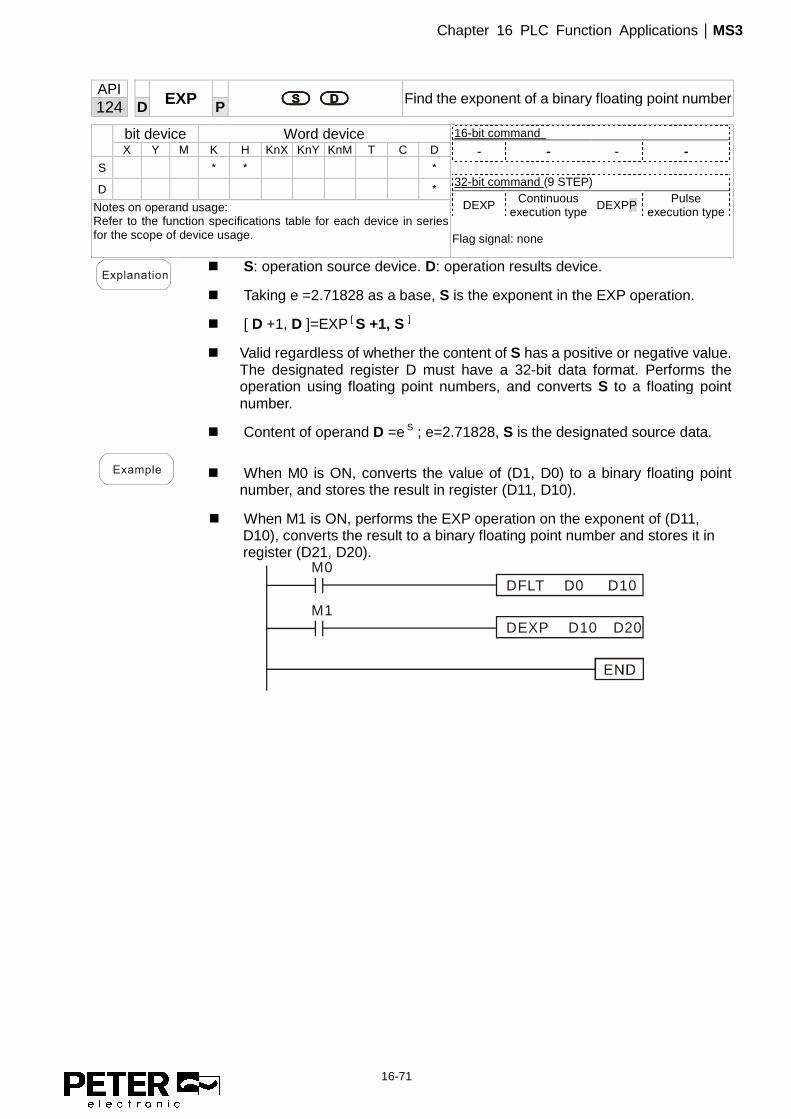
Chapter 16 PLC Function Applications|MS3
16-71
API
EXP
Find the exponent of a binary floating point number 124 D P
bit device Word device 16-bit command
- - - - 32-bit command (9 STEP)
DEXP Continuous execution type DEXPP Pulse
execution type Flag signal: none
X Y M K H KnX KnY KnM T C D
S * * *
D *
Notes on operand usage: Refer to the function specifications table for each device in series for the scope of device usage.
� S: operation source device. D: operation results device.
� Taking e =2.71828 as a base, S is the exponent in the EXP operation.
� [ D +1, D ]=EXP [ S +1, S ]
� Valid regardless of whether the content of S has a positive or negative value. The designated register D must have a 32-bit data format. Performs the operation using floating point numbers, and converts S to a floating point number.
� Content of operand D =e S ; e=2.71828, S is the designated source data.
� When M0 is ON, converts the value of (D1, D0) to a binary floating point number, and stores the result in register (D11, D10).
� When M1 is ON, performs the EXP operation on the exponent of (D11, D10), converts the result to a binary floating point number and stores it in register (D21, D20).
M0
M1
DFLT D0 D10
DEXP D10 D20

Chapter 16 PLC Function Applications|MS3
16-72
API
LN
Find the natural logarithm of a binary floating point 125 D P
bit device Word device 16-bit command
- - - - 32-bit command (9 STEP)
DLN Continuous execution type DLNP Pulse
execution type Flag signal: none
X Y M K H KnX KnY KnM T C D
S * * *
D *
Notes on operand usage: Refer to the function specifications table for each device in series for the scope of device usage.
� S: operation source device. D: operation results device.
� Taking e =2.71828 as a base, S is the exponent in the EXP operation.
� [ D +1, D ]=EXP [ S +1, S ]
� Valid regardless of whether the content of S has a positive or negative value. The designated register D must have a 32-bit data format. Performs the operation using floating point numbers and converts S to a floating point number.
� Content of operand D =e S ; e=2.71828, S is the designated source data
� When M0 is ON, converts the value of (D1, D0) to a binary floating point number, and stores the result in register (D11, D10).
� When M1 is ON, performs the EXP operation on the exponent of (D11, D10); converts the result to a binary floating point number stores it in register (D21, D20).
M0
M1
DFLT D0 D10
DLN D10 D20
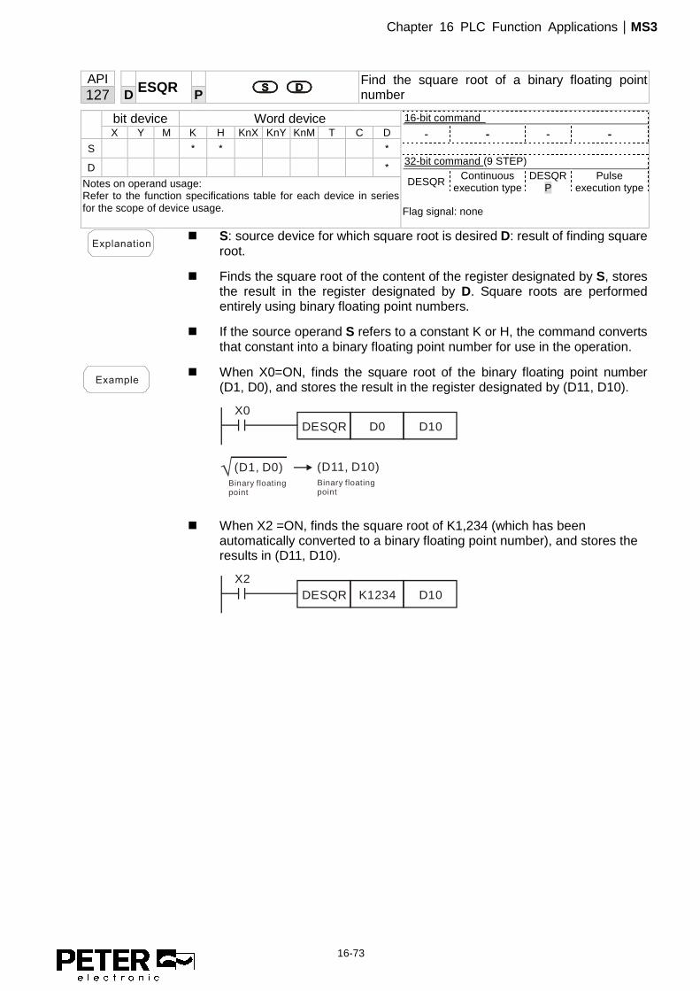
Chapter 16 PLC Function Applications|MS3
16-73
API
ESQR
Find the square root of a binary floating point number 127 D P
bit device Word device 16-bit command
- - - - 32-bit command (9 STEP)
DESQR Continuous execution type
DESQRP
Pulse execution type
Flag signal: none
X Y M K H KnX KnY KnM T C D
S * * *
D *
Notes on operand usage: Refer to the function specifications table for each device in series for the scope of device usage.
� S: source device for which square root is desired D: result of finding square root.
� Finds the square root of the content of the register designated by S, stores the result in the register designated by D. Square roots are performed entirely using binary floating point numbers.
� If the source operand S refers to a constant K or H, the command converts that constant into a binary floating point number for use in the operation.
� When X0=ON, finds the square root of the binary floating point number
(D1, D0), and stores the result in the register designated by (D11, D10).
X0DESQR D0 D10
(D1, D0) (D11, D10)Binary floating point
Binary floating point
� When X2 =ON, finds the square root of K1,234 (which has been automatically converted to a binary floating point number), and stores the results in (D11, D10).
X2DESQR K1234 D10

Chapter 16 PLC Function Applications|MS3
16-74
API
INT
Convert binary floating point number to BIN whole number 129 D P
bit device Word device 16-bit command
- - - - 32-bit command (9 STEP)
DINT Continuous execution type DINTP Pulse
execution type Flag signal: none
X Y M K H KnX KnY KnM T C D
S *
D *
Notes on operand usage: Refer to the function specifications table for each device in series for the scope of device usage.
� S: the source device to be converted. D: results of conversion.
� Converts the content of the register designated by S from a binary floating point number format to a BIN whole number, and stores the results in D. The BIN whole number floating point number is discarded.
� The action of this command is the opposite of that of command API 49 (FLT).
� When X0=ON, converts the binary floating point number (D1, D0) into a
BIN whole number, and stores the result in (D10); the BIN whole number floating point number is discarded.
X0DINT D0 D10
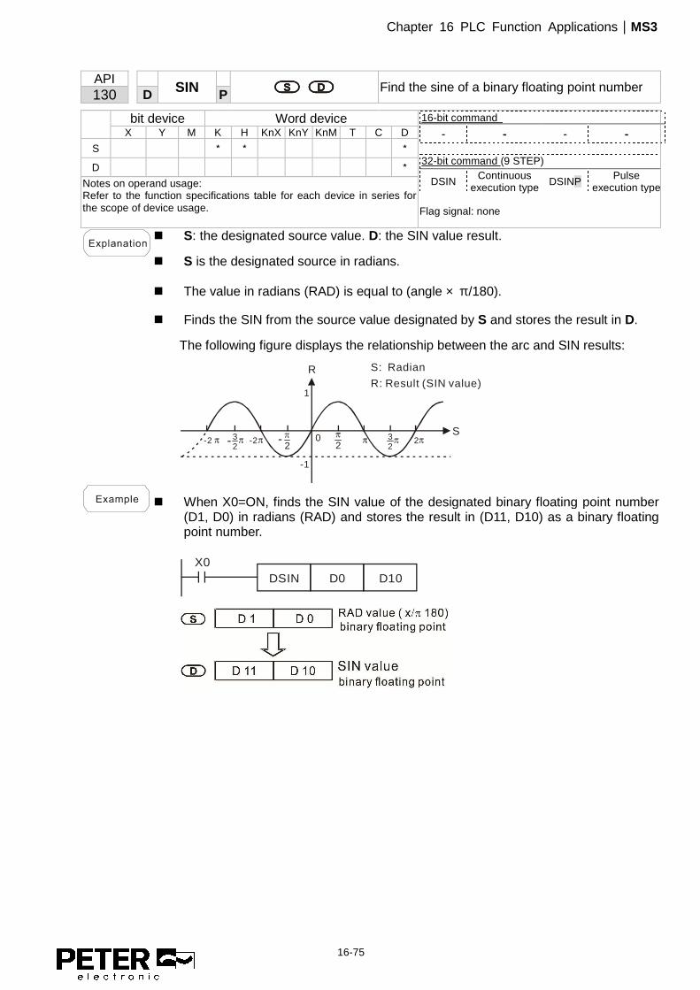
Chapter 16 PLC Function Applications|MS3
16-75
API
SIN
Find the sine of a binary floating point number 130 D P
bit device Word device 16-bit command
- - - - 32-bit command (9 STEP)
DSIN Continuous execution type DSINP Pulse
execution type Flag signal: none
X Y M K H KnX KnY KnM T C D
S * * *
D *
Notes on operand usage: Refer to the function specifications table for each device in series for the scope of device usage.
� S: the designated source value. D: the SIN value result.
� S is the designated source in radians.
� The value in radians (RAD) is equal to (angle × π/180).
� Finds the SIN from the source value designated by S and stores the result in D.
The following figure displays the relationship between the arc and SIN results:
R
S
S: Radian
R: Result (SIN value)
-2 32
-2 23222
-
1
-1
0-
� When X0=ON, finds the SIN value of the designated binary floating point number (D1, D0) in radians (RAD) and stores the result in (D11, D10) as a binary floating point number.
X0DSIN D0 D10

Chapter 16 PLC Function Applications|MS3
16-76
API
COS
Find the cosine of a binary floating point number 131 D P
bit device Word device 16-bit command
- - - - 32-bit command (9 STEP)
DCOS Continuous execution type DCOSP Pulse
execution type Flag signal: none
X Y M K H KnX KnY KnM T C D
S * * *
D *
Notes on operand usage: Refer to the function specifications table for each device in series for the scope of device usage.
� S: the designated source value. D: the COS value result.
� Finds the COS of the source value designated by S and stores it in D.
The following figure displays the relationship between the arc and COS results:
R
S-2 3
2-2 23
222-
1
-1
0-
S: Radian
R: Result (COS value)
� When X0=ON, finds the COS value of the designated binary floating point number (D1, D0) in radians and stores the result in (D11, D10), as a binary floating point number.
X0DCOS D0 D10
D 1 D 0
D 1 D 10COS valuebinary floating point
binary floating point RAD value ( x 180)π/

Chapter 16 PLC Function Applications|MS3
16-77
API
TAN
Find the tangent of a binary floating point number 132 D P
bit device Word device 16-bit command
- - - - 32-bit command (9 STEP)
DTAN Continuous execution type DTANP Pulse
execution type Flag signal: none
X Y M K H KnX KnY KnM T C D
S * * *
D *
Notes on operand usage: Refer to the function specifications table for each device in series for the scope of device usage.
� S: the designated source value. D: the TAN value result.
� Finds the TAN of the source value designated by S and stores it in D.
The following figure displays the relationship between the arc and TAN results:
� When X0=ON, finds the TAN value of the designated binary floating point number (D1, D0) in radians (RAD) and stores it in (D11, D10), as a binary floating point number.
X0DTAN D0 D10
D 1 D 0
D 11 D 10
RAD value (degree x 180)π / binary floating point
TAN valuebinary floating point

Chapter 16 PLC Function Applications|MS3
16-78
API
ASIN
Find the arcsine of a binary floating point number 133 D P
bit device Word device 16-bit command
- - - - 32-bit command (9 STEP)
DASIN Continuous execution type DASINP Pulse
execution type Flag signal: none
X Y M K H KnX KnY KnM T C D
S * * *
D *
Notes on operand usage: Refer to the function specifications table for each device in series for the scope of device usage.
� S: the designated source (binary floating point number). D: the ASIN value result.
� ASIN value =sin-1
The figure below shows the relationship between input data and result:
R
S
2
2-
0 1,0-1,0
S: Input (SIN value)R: Result (ASIN value)
� When X0=ON, finds the ASIN value of the designated binary floating point number (D1, D0) and stores the result in (D11, D10), as a binary floating point number.
X0DASIN D0 D10
D 1 D 0
D 11 D 10ASIN valuebinary floating point
Binary floating point

Chapter 16 PLC Function Applications|MS3
16-79
API
ACOS
Find the arccosine of a binary floating point number 134 D P
bit device Word device 16-bit command
- - - - 32-bit command (9 STEP)
DACOS Continuous execution type
DACOSP
Pulse execution type
Flag signal: none
X Y M K H KnX KnY KnM T C D
S * * *
D *
Notes on operand usage: Refer to the function specifications table for each device in series for the scope of device usage.
� S: the designated source (binary floating point number). D: the ACOS value result.
� ACOS value =cos-1
The figure below shows the relationship between input data and result:
R
S
2
0 1,0-1,0
S: Input (COS value)R: Result (ACOS value)
� When X0=ON, finds the ACOS value of the designated binary floating point number (D1, D0) and stores the result in (D11, D10), as a binary floating point number.
X0DACOS D0 D10
D 1 D 0
D 10ACOS value
Binary floating point
D 11

Chapter 16 PLC Function Applications|MS3
16-80
API
ATAN
Find the arctangent of a binary floating point number 135 D P
bit device Word device 16-bit command
- - - - 32-bit command (9 STEP)
DATAN Continuous execution type DATANP Pulse
execution type Flag signal: none
X Y M K H KnX KnY KnM T C D
S * * *
D *
Notes on operand usage: Refer to the function specifications table for each device in series for the scope of device usage.
� S: the designated source (binary floating point number). D: the ATAN value result.
� ATAN value =tan-1
The figure below shows the relationship between input data and result:
R
S
2
2-
0
S: Input (TAN value)R: Result (ATAN value)
� When X0=ON, finds the ATAN value of the designated binary floating point number (D1, D0) and stores the result in (D11, D10), as a binary floating point number.
X0DATAN D0 D10
D 1 D 0
D 10D 11
Binary floating point
ATAN valuebinary floating point

Chapter 16 PLC Function Applications|MS3
16-81
API
SINH
Find the hyperbolic sine of at binary floating point number 136 D P
bit device Word device 16-bit command
- - - - 32-bit command (9 STEP)
DSINH Continuous execution type DSINHP Pulse
execution type Flag signal: none
X Y M K H KnX KnY KnM T C D
S * * *
D *
Notes on operand usage: Refer to the function specifications table for each device in series for the scope of device usage.
� S: the designated source (binary floating point number). D: the SINH value result.
� SINH value =(es-e-s)/2
� When X0=ON, finds the SINH value of the designated binary floating point number (D1, D0) and stores the result in (D11, D10), as a binary floating point number.
X0DSINH D0 D10
D 1 D 0
D 10SINH value binary floating point
binary floating point
D 11

Chapter 16 PLC Function Applications|MS3
16-82
API
COSH
Find the hyperbolic cosine of a binary floating point number 137 D P
bit device Word device 16-bit command
- - - - 32-bit command (9 STEP)
DCOSH Continuous execution type DCOSHP Pulse
execution type Flag signal: none
X Y M K H KnX KnY KnM T C D
S * * *
D *
Notes on operand usage: Refer to the function specifications table for each device in series for the scope of device usage.
� S: the designated source (binary floating point number). D: the COSH value result.
� COSH value =(es+e-s)/2
� When X0=ON, finds the COSH value of the designated binary floating point number (D1, D0) and stores the result in (D11, D10), as a binary floating point number.
X0DCOSH D0 D10
D 1 D 0
D 10COSH valuebinary floating point
binary floating point
D 11

Chapter 16 PLC Function Applications|MS3
16-83
API
TANH
Finds the hyperbolic tangent of a binary floating point number 138 D P
bit device Word device 16-bit command
- - - - 32-bit command (9 STEP)
DTANH Continuous execution type DTANHP Pulse
execution type Flag signal: none
X Y M K H KnX KnY KnM T C D
S * * *
D *
Notes on operand usage: Refer to the function specifications table for each device in series for the scope of device usage.
� S: the designated source (binary floating point number). D: the TANH value result.
� TANH value =(es-e-s)/(es+e-s)
� When X0=ON, finds the TANH value of the designated binary floating point number (D1, D0) and stores the result in (D11, D10), as a binary floating point number.
X0DTANH D0 D10
D 1 D 0
D 10 TANH valuebinary floating point
binary floating point
D 11
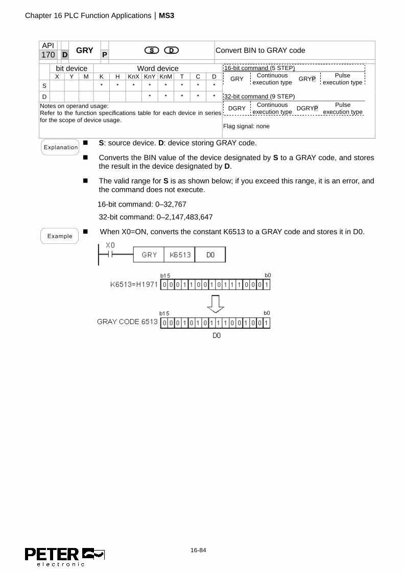
Chapter 16 PLC Function Applications|MS3
16-84
API
GRY
Convert BIN to GRAY code 170 D P
bit device Word device 16-bit command (5 STEP)
GRY Continuous execution type GRYP Pulse
execution type 32-bit command (9 STEP)
DGRY Continuous execution type DGRYP Pulse
execution type Flag signal: none
X Y M K H KnX KnY KnM T C D
S * * * * * * * *
D * * * * *
Notes on operand usage: Refer to the function specifications table for each device in series for the scope of device usage.
� S: source device. D: device storing GRAY code.
� Converts the BIN value of the device designated by S to a GRAY code, and stores the result in the device designated by D.
� The valid range for S is as shown below; if you exceed this range, it is an error, and the command does not execute.
16-bit command: 0–32,767
32-bit command: 0–2,147,483,647
� When X0=ON, converts the constant K6513 to a GRAY code and stores it in D0.

Chapter 16 PLC Function Applications|MS3
16-85
API
GBIN
Convert GRAY code to BIN 171 D P
bit device Word device 16-bit command (5 STEP)
GBIN Continuous execution type GBINP Pulse
execution type 32-bit command (9 STEP)
DGBIN Continuous execution type DGBINP Pulse
execution type Flag signal: none
X Y M K H KnX KnY KnM T C D
S * * * * * * * *
D * * * * *
Notes on operand usage: Refer to the function specifications table for each device in series for the scope of device usage.
� S: source device storing GRAY code. D: device storing BIN value after conversion.
� Converts the GRAY code corresponding to the value of the device designated by S that is converted into a BIN value, and stores it in the device designated by D.
� This command converts the value of the absolute position encoder connected with the PLC's input (this encoder usually has an output value in the form of GRAY code) into a BIN value, and stores it in the designated register.
� The valid range of S is as shown below; if you exceed this range, it is an error, and the command does not execute.
16-bit command: 0–32,767
32-bit command: 0–2,147,483,647
� When X20=ON, converts the GRAY code of the absolute position encoder
connected with input points X0–X17 to a BIN value and stores it in D10.
X20GBIN K4X0 D10
0 0 0 1 10 11 10 0 0
b15 b0
H1971=K6513 0 0 0 0 0 0 111111
X17 X0
GRAY CODE 6513
K4X0
0 1 0 1
0 0 1 0

Chapter 16 PLC Function Applications|MS3
16-86
API
LD#
S1 S2 Contact form logical operation LD# 215– 217 D
bit device Word device 16-bit command (5 STEP)
LD# Continuous execution type - -
32-bit command (9 STEP)
DLD# Continuous execution type - -
Flag signal: none
X Y M K H KnX KnY KnM T C D
S1 * * * * * * * *
S2 * * * * * * * * Notes on operand usage: #,:, &, |, ^ Refer to the function specifications table for each device in series for the range of device usage.
� S1: data source device 1. S2: data source device 2.
� This command compares the contents of S1 and S2. When the result of comparison is not 0, this command activates; when the result of comparison is 0, this command does not activate.
� You can use the LD# command directly to connect with the busbar
API No. 16-bit
commands 32-bit
commands Conditions for
activation
Conditions for
inactivation
215 LD& DLD& S1 & S2 ≠ 0 S1 & S2 = 0
216 LD| DLD| S1 | S2 ≠ 0 S1 | S2 = 0
217 LD^ DLD^ S1 ^ S2 ≠ 0 S1 ^ S2 = 0
&: logical AND operation.
|: logical OR operation.
^: logical XOR operation.
� When you compare the contents of C0 and C10 with the logical AND operation,
and the result is not equal to 0, then Y10=ON. � When you compare the content of D200 and D300 with the logical OR operation,
and the result is not equal to 0, and X1=ON, then Y11=ON and remains in that state.
LD C0 C10
LD D200 D300 SETX1
&
I Y11
Y10

Chapter 16 PLC Function Applications|MS3
16-87
API
AND#
S1 S2 Contact form logical operation AND# 218– 220 D
bit device Word device 16-bit command (5 STEP)
AND# Continuous execution type - -
32-bit command (9 STEP)
DAND# Continuous execution type - -
Flag signal: none
X Y M K H KnX KnY KnM T C D
S1 * * * * * * * *
S2 * * * * * * * * Notes on operand usage:: #,:, &, |, ^ Refer to the function specifications table for each device in series for the scope of device usage.
� S1: data source device 1. S2: data source device 2.
� This command compares the contents of S1 and S2. When the result of comparison is not 0, this command activates; when the result of comparison is 0, this command does not activate.
� The AND# command is an operation command in series with the contact.
API No. 16-bit
commands 32-bit
commands Conditions for
activation
Conditions for
inactivation
218 AND& DAND& S1 & S2 ≠ 0 S1 & S2 = 0
219 AND| DAND| S1 | S2 ≠ 0 S1 | S2 = 0
220 AND^ DAND^ S1 ^ S2 ≠ 0 S1 ^ S2 = 0
&: logical AND operation.
|: logical OR operation.
^: logical XOR operation.
� When X0=ON and you compare the contents of C0 and C10 with the logical
AND operation, and the result is not equal to 0, then Y10=ON. � When X1=OFF and you compare the contents D10 and D0 with the logical OR
operation, and the result is not equal to 0, then Y11=ON and remains in that state. � When X2 =ON and you compare the contents of the 32-bit register D200 (D201)
and the 32-bit register D100 (D101) with the logical XOR operation, and the result is not equal to 0 or M3=ON, then M50=ON.
M3
DAND D200 D100 M50
AND C0 C10
AND D10 D0 SET
&
^
I Y11
Y10X0
X1
X2

Chapter 16 PLC Function Applications|MS3
16-88
API
OR#
S1 S2 Contact form logical operation OR# 221– 223 D
bit device Word device 16-bit command (5 STEP)
OR# Continuous execution type - -
32-bit command (9 STEP)
DOR# Continuous execution type - -
Flag signal: none
X Y M K H KnX KnY KnM T C D
S1 * * * * * * * *
S2 * * * * * * * * Notes on operand usage: #,:, &, |, ^ Refer to the function specifications table for each device in series for the scope of device usage.
� S1: data source device 1. S2: data source device 2.
� This command compares the contents of S1 and S2. When the result of comparison is not 0, this command activates; when the result of comparison is 0, this command does not activate.
� The OR# command is an operation command in series with the contact.
API No. 16-bit
commands 32-bit
commands Conditions for
activation
Conditions for
inactivation
221 OR& DOR& S1 & S2 ≠ 0 S1 & S2 = 0
222 OR| DOR| S1 | S2 ≠ 0 S1 | S2 = 0
223 OR^ DOR^ S1 ^ S2 ≠ 0 S1 ^ S2 = 0
&: logical AND operation.
|: logical OR operation.
^: logical XOR operation.
� When X1=ON or you compare the contents of C0 and C10 with the logical
AND operation, and the result is not equal to 0, then Y0=ON. � When X2 and M30 are both equal to ON, or you compare the contents of the
32-bit register D10 (D11) and the 32-bit register D20 (D21) with the logical OR operation, and the result is not equal to 0, or you compare the contents of the 32-bit counter C235 and the 32-bit register D200 (D201) with the logical XOR operation, and the result is not equal to 0, then M60=ON.
OR C0 C10
DOR D10 D20
&
I
Y0
X2
X1
M30M60
DOR D25 D200^
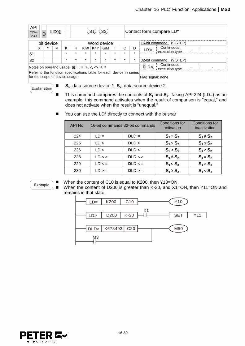
Chapter 16 PLC Function Applications|MS3
16-89
API
LD※
S1 S2 Contact form compare LD* 224– 230 D
bit device Word device 16-bit command (5 STEP)
LD※ Continuous
execution type - -
32-bit command (9 STEP)
DLD※ Continuous
execution type - -
Flag signal: none
X Y M K H KnX KnY KnM T C D
S1 * * * * * * * *
S2 * * * * * * * *
Notes on operand usage: ※,: , =, >, <, <>, ≤, ≥ Refer to the function specifications table for each device in series for the scope of device usage.
� S1: data source device 1. S2: data source device 2.
� This command compares the contents of S1 and S2. Taking API 224 (LD=) as an example, this command activates when the result of comparison is "equal," and does not activate when the result is "unequal."
� You can use the LD* directly to connect with the busbar
API No. 16-bit commands 32-bit commands Conditions for
activation Conditions for
inactivation
224 LD = DLD = S1 = S2 S1 ≠ S2
225 LD > DLD > S1 > S2 S1 ≤ S2
226 LD < DLD < S1 < S2 S1 ≥ S2
228 LD < > DLD < > S1 ≠ S2 S1 = S2
229 LD < = DLD < = S1 ≤ S2 S1 > S2
230 LD > = DLD > = S1 ≥ S2 S1 < S2
� When the content of C10 is equal to K200, then Y10=ON. � When the content of D200 is greater than K-30, and X1=ON, then Y11=ON and
remains in that state.
LD= K200 C10
DLD> K678493 C20
M3
Y10
LD> D200 K-30 SET Y11
M50
X1

Chapter 16 PLC Function Applications|MS3
16-90
API
AND※
S1 S2 Contact form compare AND* 232– 238 D
bit device Word device 16-bit command (5 STEP)
AND※ Continuous
execution type - -
32-bit command (9 STEP)
DAND※ Continuous
execution type - -
Flag signal: none
X Y M K H KnX KnY KnM T C D
S1 * * * * * * * *
S2 * * * * * * * *
Notes on operand usage: ※,: , =, >, <, <>, ≤, ≥ Refer to the function specifications table for each device in series for the scope of device usage.
� S1: data source device 1. S2: data source device 2.
� This command compares the contents of S1 and S2. Taking API 232 (AND=) as an example, when the result of comparison is “equal”, this command activates; when the result of comparison is “unequal”, this command does not activate.
� The AND* command is a comparison command in series with a contact.
API No. 16-bit commands 32-bit commands Conditions for
activation Conditions for
inactivation
232 AND = DAND = S1 = S2 S1 ≠ S2
233 AND > DAND > S1 > S2 S1 ≤ S2
234 AND < DAND < S1 < S2 S1 ≥ S2
236 AND < > DAND < > S1 ≠ S2 S1 = S2
237 AND < = DAND < = S1 ≤ S2 S1 > S2
238 AND > = DAND > = S1 ≥ S2 S1 < S2
� When X0=ON and the current value of C10 is also equal to K200, then Y10=ON. � When X1=OFF and the content of register D0 is not equal to K-10, then Y11=ON
and remains in that state. � When X2 =ON and the content of the 32-bit register D0 (D11) is less than
678,493, or M3=ON, then M50=ON.
AND= K200 C10
DAND> K678493 D10
M3
Y10
AND<> K-10 D0 SET Y11
M50X2
X1
X0

Chapter 16 PLC Function Applications|MS3
16-91
API
OR※
S1 S2 Contact form compare OR* 240– 246 D
bit device Word device 16-bit command (5 STEP)
OR※ Continuous
execution type - -
32-bit command (9 STEP)
DOR※ Continuous
execution type - -
Flag signal: none
X Y M K H KnX KnY KnM T C D
S1 * * * * * * * *
S2 * * * * * * * *
Notes on operand usage: ※,: , =, >, <, <>, ≤, ≥ Refer to the function specifications table for each device in series for the scope of device usage.
� S1: data source device 1. S2: data source device 2.
� This command compares the contents of S1 and S2. Taking API 240 (OR=) as an example, when the result of comparison is “equal”, this command activates; when the result of comparison is “unequal”, this command does not activate.
� The OR* command is a comparison command in parallel with a contact.
API No. 16-bit commands 32-bit commands Conditions for
activation Conditions for
inactivation 240 OR = DOR = S1 = S2 S1 ≠ S2 241 OR > DOR > S1 > S2 S1 ≤ S2 242 OR < DOR < S1 < S2 S1 ≥ S2 244 OR < > DOR < > S1 ≠ S2 S1 = S2 245 OR < = DOR < = S1 ≤ S2 S1 > S2 246 OR > = DOR > = S1 ≥ S2 S1 < S2
� When X0=ON and the current value of C10 is also equal to K200, then Y10=ON. � When X1=OFF and the content of register D0 is not equal to K-10, then Y11=ON
and remains in that state. � When X2 =ON and the content of the 32-bit register D0 (D11) is less than
678,493, or M3=ON, then M50=ON.
X2 M30M60
OR>= K200 C10
X1Y0
DOR>= D100 K100000

Chapter 16 PLC Function Applications|MS3
16-92
API
FLD※
S1 S2 Floating point number contact form compare LD* 275– 280
bit device Word device 16-bit command - - - -
32-bit command (9 STEP)
FLD※ Continuous
execution type - -
Flag signal: none
X Y M K H KnX KnY KnM T C D
S1 * * *
S2 * * *
Notes on operand usage: ※,: , =, >, <, <>, ≤, ≥ Refer to the function specifications table for each device in series for the scope of device usage.
� S1: data source device 1. S2: data source device 2.
� This command compares the contents of S1 and S2. Taking "FLD=" as an example, if the result of comparison is “equal”, this command activates; but it does not activate when the result is “unequal”.
� The FLD* command can directly input floating point numbers (for instance: F1.2) to the S1, S2 operands, or store floating point numbers in register D for use in operations.
� You can use this command while directly to connect with the busbar
API No. 32-bit commands Conditions for
activation Conditions for
inactivation
275 FLD = S1 = S2 S1 ≠ S2
276 FLD > S1 > S2 S1 ≤ S2
277 FLD < S1 < S2 S1 ≥ S2
278 FLD < > S1 ≠ S2 S1 = S2
279 FLD < = S1 ≤ S2 S1 > S2
280 FLD > = S1 ≥ S2 S1 < S2
� When the floating point number in register D200 (D201) is less than or equal to F1.2, and X1 is activated, then contact Y21 activates and remains in that state.
FLD<= D200 F1.2X1
SET Y21

Chapter 16 PLC Function Applications|MS3
16-93
API
FAND※
S1 S2 Floating point number contact form compare AND* 281– 286
bit device Word device 16-bit command - - - -
32-bit command (9 STEP)
FAND※ Continuous
execution type - -
Flag signal: none
X Y M K H KnX KnY KnM T C D
S1 * * *
S2 * * *
Notes on operand usage: ※,:, =, >, <, <>, ≤, ≥ Refer to the function specifications table for each device in series for the scope of device usage.
� S1: data source device 1. S2: data source device 2.
� This command compares the contents of S1 and S2. Taking "FAND=" as an example, if the result of comparison is “equal”, this command activates; but it does not activate when the result is “unequal”.
� The FAND* command can directly input floating point numbers (for instance: F1.2) to the S1 and S2 operands, or store the floating point numbers in register D for use in operations.
� You can use this command directly to connect with the busbar.
API No. 32-bit commands Conditions for
activation Conditions for
inactivation
281 FAND = S1 = S2 S1 ≠ S2
282 FAND > S1 > S2 S1 ≤ S2
283 FAND < S1 < S2 S1 ≥ S2
284 FAND < > S1 ≠ S2 S1 = S2
285 FAND < = S1 ≤ S2 S1 > S2
286 FAND > = S1 ≥ S2 S1 < S2
� When X1=OFF, and the floating point number in register D100 (D101) is not
equal to F1.2, then Y21=ON and remains in that state.
FAND<> F1.2 D0 SET Y21X1

Chapter 16 PLC Function Applications|MS3
16-94
API
FOR※
S1 S2 Floating point number contact form compare OR* 287– 292
bit device Word device 16-bit command - - - -
32-bit command (9 STEP)
FOR※ Continuous
execution type - -
Flag signal: none
X Y M K H KnX KnY KnM T C D
S1 * * *
S2 * * *
Notes on operand usage: ※,:, =, >, <, <>, ≤, ≥ Refer to the function specifications table for each device in series for the scope of device usage.
� S1: data source device 1. S2: data source device 2.
� This command compares the contents of S1 and S2. Taking "FOR=" as an example, if the result of comparison is “equal”, this command activates; but it does not activate when the result is “unequal”.
� The FOR* command can directly input floating point numbers (for instance: F1.2) to the S1, S2 operands, or store floating point numbers in register D for use in operations.
� You can use this command directly to connect with the busbar.
API No. 32-bit commands Conditions for
activation Conditions for
inactivation
287 FOR = S1 = S2 S1 ≠ S2
288 FOR > S1 > S2 S1 ≤ S2
289 FOR < S1 < S2 S1 ≥ S2
290 FOR < > S1 ≠ S2 S1 = S2
291 FOR < = S1 ≤ S2 S1 > S2
292 FOR > = S1 ≥ S2 S1 < S2
� When X2 and M30 are both equal to ON, or the floating point number in register D100 (D101) is greater than or equal to F1.234, then M60=ON.
FOR>= D100 F1.234
X2 M30M60

Chapter 16 PLC Function Applications|MS3
16-95
16-6-5 Detailed explanation of drive special application commands
API RPR
S1 S2 Read servo parameter 139 P
bit device Word device 16-bit command (5 STEP)
RPR Continuous execution type RPRP Pulse
execution type 32-bit command
- - - - Flag signal: none
X Y M K H KnX KnY KnM T C D
S1 * * *
S2 *
Notes on operand usage: none
� S1 : Parameter address of data to be read. S2 : Register where data that is
read is stored.
API WPR
S1 S2 Write servo parameter 140 P
bit device Word device 16-bit command (5 STEP)
WPR Continuous execution type WPRP Pulse
execution type 32-bit command
- - - - Flag signal: M1016 parameter read/write error, M1017 parameter written successfully.
X Y M K H KnX KnY KnM T C D
S1 * * *
S2 * * *
Notes on operand usage: none
� S1 : Data to write to specified page. S2 : Parameter address of data to be
written.
� When the data in the MS3 drive's parameter H01.00 is read and written to D0,
data from H01.01 is read and written to D1. � When M0=ON, the content of D10 is written to the MS3 drive Pr.04.00 (first
speed of multiple speed levels). � When M1017=ON, the parameter has been written successfully. � The MS3's WPR command does not support writing to the 20XX address, but
the RPR command supports reading of 21XX, 22XX.
Recommendation Be cautious when using the WPR command. When writing parameters, most
parameters are recorded when they are written, and these parameters may only be revised 106 times: a memory write error may occur if parameters are written more than (MS)106 or (MH)109 times.
The number of times a parameter is written is based on whether the written value is modified. For instance, writing the same value 100 times at the same time counts as writing only once.
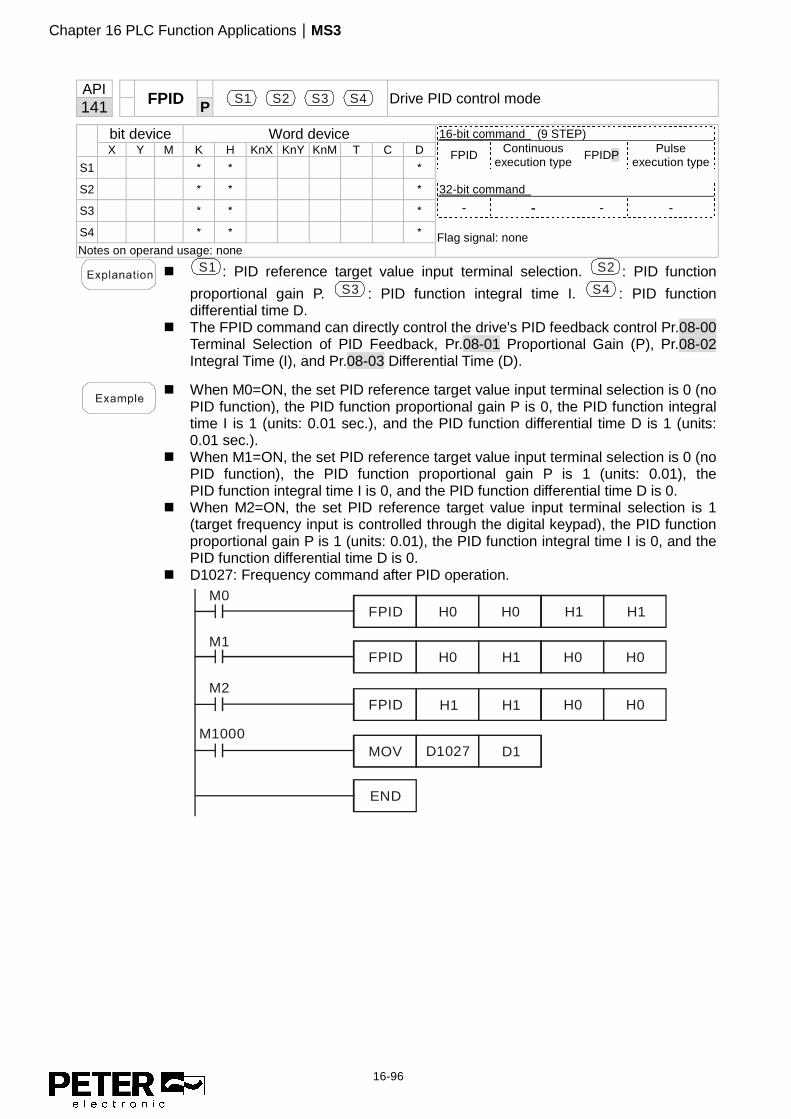
Chapter 16 PLC Function Applications|MS3
16-96
API
FPID
S1 S2 S3 S4 Drive PID control mode 141 P
bit device Word device 16-bit command (9 STEP)
FPID Continuous execution type FPIDP Pulse
execution type 32-bit command
- - - - Flag signal: none
X Y M K H KnX KnY KnM T C D
S1 * * *
S2 * * *
S3 * * *
S4 * * *
Notes on operand usage: none
� S1 : PID reference target value input terminal selection. S2 : PID function
proportional gain P. S3 : PID function integral time I. S4 : PID function differential time D.
� The FPID command can directly control the drive's PID feedback control Pr.08-00 Terminal Selection of PID Feedback, Pr.08-01 Proportional Gain (P), Pr.08-02 Integral Time (I), and Pr.08-03 Differential Time (D).
� When M0=ON, the set PID reference target value input terminal selection is 0 (no
PID function), the PID function proportional gain P is 0, the PID function integral time I is 1 (units: 0.01 sec.), and the PID function differential time D is 1 (units: 0.01 sec.).
� When M1=ON, the set PID reference target value input terminal selection is 0 (no PID function), the PID function proportional gain P is 1 (units: 0.01), the PID function integral time I is 0, and the PID function differential time D is 0.
� When M2=ON, the set PID reference target value input terminal selection is 1 (target frequency input is controlled through the digital keypad), the PID function proportional gain P is 1 (units: 0.01), the PID function integral time I is 0, and the PID function differential time D is 0.
� D1027: Frequency command after PID operation.
END
H0
M2
M1
M0
M1000
H1
H0
H0
H1
H1
H1 H1
H0 H0
H0 H0
FPID
MOV D1027 D1
FPID
FPID

Chapter 16 PLC Function Applications|MS3
16-97
API
FREQ
S1 S2 S3 Drive speed control mode 142 P
bit device Word device 16-bit command (7 STEP)
FREQ Continuous execution type FREQP Pulse
execution type 32-bit command
- - - - Flag signal: M1015
X Y M K H KnX KnY KnM T C D
S1 * * *
S2 * * *
S3 * * *
Notes on operand usage: none
� S1 : Frequency command. S2 : Acceleration time. S3 : Deceleration time � S2,S3: In the acceleration and deceleration time settings, the number of decimal
places is determined by the definition in Pr.01-45. Example When Pr.01-45=0: units of 0.01 sec. A setting of S2=50 (acceleration time) in the ladder diagram below implies 0.5 sec., and the S3 (deceleration time) setting of 60 implies 0.6 sec.. � The FREQ command can control drive Frequency commands, and acceleration
and deceleration time. It also uses special register control actions, such as: M1025: Control drive RUN(ON)/STOP(OFF) (RUN requires Servo On (M1040
ON) to be effective) M1026: Control drive operating direction FWD(OFF)/REV(ON) M1040: Control Servo On/Servo Off. M1042: Trigger Quick Stop (ON)/does not trigger Quick Stop (OFF). M1044: Pause (ON)/release pause (OFF) M1052: Lock frequency (ON)/release lock frequency (OFF)
� M1025: Drive RUN (ON)/STOP (OFF), M1026: drive operating
direction FWD(OFF)/REV(ON). M1015: frequency reached. � When M10=ON, sets the drive frequency command K300 (3.00 Hz) with an
acceleration and deceleration time of 0. When M11=ON, sets the drive frequency command K3000 (30.00 Hz), with an acceleration time of 50 (0.5 sec.) and deceleration time of 60 (0.6 sec.) (when Pr.01-45=0).
� When M11=OFF, the drive frequency command changes to 0.
END
M13M1044
FREQP K300 K0 K0
FREQ K3000 K50 K60
M11M10
M10M11
M1000M1040
M12M1042
M1000M1025
M11M1026
M14M1052
� Pr.09-33 are defined on the basis of whether reference commands have been
cleared before the PLC operation

Chapter 16 PLC Function Applications|MS3
16-98
bit 0 : Prior to PLC scanning procedures, acts on whether the target frequency
has been cleared to 0. This is written to the FREQ command when the PLC
is ON.
bit 1 : Prior to PLC scanning procedures, acts on whether the target torque has
been cleared to 0. This is written to the TORQ command when the PLC is
ON.
bit 2 : Prior to PLC scanning procedures, acts on whether speed limits in the
torque mode have been cleared to 0. This is written to the TORQ command
when the PLC is ON.
Example: When using r to write a program,
END
K2000M0
K1000 K1000FREQ
If we force M0 to 1, the frequency command is 20.00 Hz; but when M0 is set to 0,
there is a different situation.
Case 1: When the Pr.09-33 bit 0 is 0, and M0 is set as 0, then the frequency
command remains at 20.00 Hz.
Case 2: When the Pr.09-33 bit 0 is 1, and M0 is set as 0, then the frequency
command changes to 0.00 Hz
This is because when the Pr.09-33 bit 0 is 1 prior to PLC scanning procedures, the
frequency first reverts to 0.
When the Pr.09-33 bit 0 is 0, the frequency does not revert to 0.

Chapter 16 PLC Function Applications|MS3
16-99
16-7 Error Display and Handling
Code ID Description Recommended error resolution
PLod 50 Data writing memory error Check whether the program has an error and download the program again.
PLSv 51 Data write memory error during program execution
Cycle the power and download the program again.
PLdA 52 Program transmission error Try uploading again; if the error persists, send it to the manufacturer for service.
PLFn 53 Command error while downloading program
Check whether the program has an error and download the program again.
PLor 54 Program exceeds memory capacity or no program.
Cycle the power and download the program again.
PLFF 55 Command error during program execution
Check whether the program has an error and download the program again.
PLSn 56 Check code error Check whether the program has an error and download the program again.
PLEd 57 Program has no END stop command.
Check whether the program has an error and download the program again.
PLCr 58 MC command has been used continuously more than nine times.
Check whether the program has an error and download the program again.
PLdF 59 Download program error Check whether the program has an error and download again.
PLSF 60 PLC scan time excessively long Check whether the program code has a writing error and download again.
*ID: Warning code

Chapter 16 PLC Function Applications|MS3
16-100
16-8 Explanation of PLC Speed Mode Control The following tables describe the control mode and setting. These are the register tables for speed
mode.
Control special M
Special M Function Description Attributes
M1025 Drive frequency = set frequency (ON) / drive frequency = 0 (OFF) RW M1026 Drive operating direction FWD (OFF) / REV (ON) RW M1040 Hardware power (Servo On) RW M1042 Quick Stop RW M1044 Pause (Halt) RW M1052 Lock frequency (lock, frequency locked at the current operating frequency) RW
Status special M
Special M Function Description Attributes
M1015 Frequency reached (when used with M1025) RO M1056 Hardware already has power (Servo On Ready) RO M1058 On Quick Stopping RO
Control special D
Special D Function Description Attributes
D1060 Mode setting (speed mode is 0) RW
Status special D
Special D Function Description Attributes
D1037 Drive output frequency (0.00–599.00 Hz) RO D1050 Actual operation mode (speed mode is 0) RO
Speed mode control commands:
FREQ(P) S1 S2 S3
Target speed The first acceleration time setting The first deceleration time setting
Example of speed mode control:
Before using speed control, if you use the FOC (magnetic field orientation) control method, you must
first complete the setting of the electro-mechanical parameters.
1. Setting D1060 = 0 shifts the drive to speed mode (default).
2. Use the FREQ command to control frequency, acceleration time, and deceleration time.
3. Setting M1040 = 1, the drive is now excited, but the frequency is 0.
4. Setting M1025 = 1, the drive Frequency command now jumps to the frequency designated
by FREQ, and acceleration and deceleration is controlled on the basis of the acceleration time
and deceleration time specified by FREQ.
5. Use M1052 to lock the current operation frequency.

Chapter 16 PLC Function Applications|MS3
16-101
6. Use M1044 to temporarily pause the operation, and the deceleration method uses the
deceleration settings.
7. Use M1042 to perform Quick Stop, and deceleration is as fast as possible without causing an
error. There may still be a jump error if the load is too large.
8. Control user rights: M1040 (Servo ON) > M1042 (Quick Stop) > M1044 (Halt) > M1052
(LOCK)

Chapter 16 PLC Function Applications|MS3
16-102
16-9 Count Function Using Pulse Input
16-9-1 High-speed count function
The MS3's MI7 supports one-way pulse counting with a maximum speed of 33 k. The starting
method is very simple, and only requires setting M1038 to begin counting. The 32-bit count value is
stored in D1054 and D1055 in non-numerical form. M1039 resets the count value to 0.
Current count valueof MI8(H word)
※ When the PLC program defines MI7 for use as a high-speed counter, that is, when M1038 or
M1039 is written in PLC procedures, other functions of MI7 are disabled.
16-9-2 Frequency calculation function
Apart from high-speed counting, the MS3's MI7 can also convert a received pulse to a frequency. The
following figure shows that there is no conflict between frequency conversion and count calculations,
which the MS3 can perform simultaneously.
PLC speed calculation formula
D1057 Speed
D1058 Interval between calculations
D1059 Decimal places
Assume that there are five input pulses each second, (see figure below) we set D1058 = 1000 ms =
1.0 second as the calculation interval. This enables five pulses to be sent to the drive each second.
Assume that each five pulses correspond to 1 Hz, we set D1057 = 5.
Setting D1059 = 2 displays numbers to two decimal places, which is also 1.00 Hz. The numerical
value displayed at D1056 is 100. For simplicity, the D1059 conversion formula can be expressed in
the following formula:

Chapter 16 PLC Function Applications|MS3
16-103
[This page intentionally left blank]