Embed Size (px)
Citation preview

WSDOT Design Manual M 22-01.12 Page 1420-1 November 2015
Chapter 1420 HOV Direct Access 1420.01 General 1420.02 HOV Access Types and Locations 1420.03 Direct Access Geometrics 1420.04 Passenger Access 1420.05 Traffic Design Elements 1420.06 Documentation 1420.07 References
1420.01 General
This chapter provides Washington State Department of Transportation (WSDOT) design guidance for left-side direct access facilities for high-occupancy vehicles (HOVs) between freeway HOV lanes and flyer stops within the freeway right of way or facilities outside of the right of way. Design right-side HOV-only access facilities in accordance with Chapter 1360.
Direct access eliminates the need for left-side HOV lane users to cross the general-purpose lanes to right-side general-purpose ramps. Also, transit vehicles can use the HOV lane and provide service to the HOV direct access facility.
Providing the HOV user access to the inside HOV lane without mixing with the general-purpose traffic saves the user additional travel time and aids in safety, enforcement, incident handling, and overall operation of the HOV facility.
Locations for direct access ramps include HOV facilities on intersecting routes, park & ride lots, flyer stops, and locations with a demonstrated demand. Coordinate with the local transit agencies to identify these key locations. Give priority to locations that serve the greatest number of transit vehicles and other HOVs.
1420.01(1) Practical Design
Under WSDOT practical design (see Chapter 1100 and Division 11) an important function of alternative solution formulation is to identify alternatives that address the baseline need while balancing the performance trade-offs identified in the process. Since HOV direct access connections are often added to existing corridors, performance tradeoffs to mainline GP lanes or other elements may be needed and acceptable to provide the new HOV connections. Document performance tradeoffs according to Chapter 1100 and Division 11.
1420.01(2) Reviews, Studies, and Reports
The practical design project development process is to be followed when developing an HOV direct access project (see Chapter 1100). Despite the nature of the projects that are the focus of this chapter, most facets of the project development process remain unchanged. For example, early coordination with others is a vital part of developing a project. There are also environmental considerations, public involvement, and value engineering studies (see Chapter 310). There may also be reviews, studies, and reports required by agreements with regional transit authorities or other agencies.

HOV Direct Access Chapter 1420
Page 1420-2 WSDOT Design Manual M 22-01.12 November 2015
Provide an interchange justification report (see Chapter 550) when there is a proposal to add, delete, or change an access point. Provide the operational analysis from the report for all flyer stops. For left-side connections, include the commitment that the connection will be used solely by HOVs or will be closed.
Throughout the project development phase, make sure the project: • Need Statement (see Chapter 1101) and cost estimate are correct. • Development process is on schedule. • Documents are biddable. • Will be constructible. • Will be maintainable.
Constructability of HOV direct access facilities is an important consideration during the design phase. These facilities will typically be constructed on existing highways with traffic maintained on-site. Key goals are to: • Provide a project that can be built. • Plan a construction strategy. • Provide a safe work zone. • Minimize construction delays.
Consider access to these facilities by maintenance crews. Avoid items that require a significant maintenance effort and might result in lane closure for routine maintenance or repair.
1420.01(3) Left-Side Connections
Left-side connections are allowed only when they serve HOVs exclusively and connect to an HOV lane. The higher traffic volume associated with general-purpose traffic is not acceptable for left-side connections. If the demand for an HOV direct access decreases to the point that the HOV direct access connection is no longer desirable, the connection must be closed.
1420.02 HOV Access Types and Locations
To provide direct access for high-occupancy vehicles from the HOV lane to a passenger loading facility, there are many options and many constraints. Following are some of the options (selected as being usable on Washington’s freeways) and constraints regarding their use.
To select an option, first establish the need, choose possible locations, evaluate site features (such as terrain, existing structures, median widths), and evaluate existing HOV information (such as lanes, park & ride facilities, transit routes and schedules, and origin and destination studies). Choose a location that meets access point spacing requirements and will not degrade traffic operations on the main line.
Important constraints to transit stop designs are: • Passenger access routes and waiting areas are separated from freeway traffic. • Passenger access to a bus is on its right side only. • Passenger access to a loading platform must accommodate the disabled.

Chapter 1420 HOV Direct Access
WSDOT Design Manual M 22-01.12 Page 1420-3 November 2015
1420.02(1) Freeway Ramp Connection Locations
1420.02(1)(a) Spacing
For minimum ramp connection spacing, see Chapter 1360. When evaluating the spacing of left-side direct access ramps, include only left-side connections.
Traffic operations can be degraded by the weaving caused by a left-side on-connection followed closely by a right-side off-connection (or a right-side on-connection followed by a left-side off-connection). As a general rule, if the spacing between the HOV direct access ramp and the general-purpose ramp is less than one gap acceptance length (see 1420.03(6)(c)) per lane, make the HOV lane buffer-separated (see Chapter 1410).
Conduct an analysis to make certain that the new ramp will not degrade traffic operations. (See Chapter 550 for the studies and report required for a new access point.)
When an off-connection follows an on-connection, provide full speed-change lane lengths and tapers or at least sufficient distance for full speed-change lanes that connect at full width with no tapers (see 1420.03(6) and (7)). An auxiliary lane can be used to connect full-width speed-change lanes if there is not sufficient distance for both tapers.
1420.02(1)(b) Sight Distance
Locate both on- and off-connections to the main line where decision sight distance exists on the main line (see Chapter 1260).
1420.02(2) Ramp Terminal Locations
1420.02(2)(a) Local Streets and Roads
Access to the HOV lane can be provided by a ramp that terminates at a local street or road. The local street or road may incorporate HOV lanes, but they are not required. (See 1420.05 for signing and pavement markings.)
Consider traffic operations on the local road. Locate the terminal where: • It has the least impact on the local road. • Intersection spacing criteria are satisfied. • Queues from adjacent intersections do not block the ramp. • Queues at the ramp do not block adjacent intersections. • Wrong-way movements are discouraged.
When off-ramps and on-ramps are opposite each other on the local road, consider incorporating a transit stop with the intersection.
1420.02(2)(b) Park & Ride Lots
HOV direct access ramps that connect the HOV lane with a park & ride lot provide easy access for express transit vehicles between the HOV lane and a local service transit stop at the park & ride facility. Other HOV traffic using the access ramp enters through the park & ride lot, which can create operational conflicts.

HOV Direct Access Chapter 1420
Page 1420-4 WSDOT Design Manual M 22-01.12 November 2015
1420.02(2)(c) Flyer Stops
Median flyer stops do not provide general access to the HOV lane. Access is from the HOV lane to the transit stop and back to the HOV lane. No other vehicle access is provided. Ramps to and from the flyer stops are restricted to transit vehicles only.
1420.02(3) Ramp Types
1420.02(3)(a) Drop Ramps
Drop ramps are generally straight, stay in the median, and connect the HOV lane with a local road or flyer stop. Following is a photo and an example of a drop ramp.
Drop ramp photograph from FHWA/PB HOV Interactive 1.0 High Occupancy Vehicle Data Base from the U.S., Canada, and Europe
On-connection
HOV lane
HOV lane
Freeway
FreewayOff-connectionMirror image ramp on
opposite side optional
Local street
Ramp on bridge or between walls
in a cut section

Chapter 1420 HOV Direct Access
WSDOT Design Manual M 22-01.12 Page 1420-5 November 2015
Consider this example for gore area characteristics for drop lanes:
Edge of through HOV lane Concrete barrier
Ramp shoulder width
Impact attenuatorEdge of ramp traveled way
Shoulder width
Ramp
Edge of traveled way
Painted nose
Edge of traveled wayEdge of shoulder
1420.02(3)(b) T Ramps
A T ramp is a median ramp that serves all four HOV access movements and comes to a T intersection within the median, usually on a structure. The structure then carries the HOV ramp over the freeway to a local road or directly to a park & ride lot. Through traffic is not permitted at the T ramp; therefore, flyer stops are not allowed. A photo and an example of a T ramp are shown for reference. Also, refer to 1420.03(10) for added design information.

HOV Direct Access Chapter 1420
Page 1420-6 WSDOT Design Manual M 22-01.12 November 2015
1420.02(3)(c) Flyover Ramps
A flyover ramp is designed to accommodate high-speed traffic by using flat curves as the ramp crosses from the median over one direction of the freeway to a local road, a park & ride lot, or an HOV lane on another freeway. A photo and an example of a flyover ramp are shown.
HOV lane
Freeway
Freeway
HOV lane
Flyover ramp photograph from FHWA/PB HOV Interactive 1.0 High Occupancy Vehicle Data Base from the U.S., Canada, and Europe

Chapter 1420 HOV Direct Access
WSDOT Design Manual M 22-01.12 Page 1420-7 November 2015
1420.02(4) Transit Stops
1420.02(4)(a) Flyer Stops
Flyer stops are transit stops inside the limited access boundaries for use by express transit vehicles using the freeway. They may be located in the median at the same grade as the main roadway or on a structure, on a ramp, or on the right side of the main line.
The advantage of a median flyer stop is that it reduces the time for express transit vehicles to serve intermediate destinations. A disadvantage is that passengers travel greater distances to reach the loading platform.
With left-side HOV lanes, flyer stops located on the right side increase the delay to the express transit vehicles by requiring them to cross the general-purpose lanes. However, these stops improve passenger access from that side of the freeway.
For additional design information, see Chapter 1430.
1. Side-Platform Flyer Stops
Side-platform flyer stops are normally located in the median and have two passenger loading platforms: one on each side between the bus loading lane and the through HOV lane. This design provides the most direct movement for the express transit vehicle and is the desirable design for median flyer stops.
This design is relatively wide. Where space is a concern, consider staggering the loading platforms longitudinally.
Consider tall barrier to divide the directions of travel or staggering the loading platforms to discourage unauthorized at-grade movement of passengers from one platform to the other (see 1420.05(1)). The side platform flyer stop with grade-separated access to each platform is the preferred design.

HOV Direct Access Chapter 1420
Page 1420-8 WSDOT Design Manual M 22-01.12 November 2015
2. At-Grade Passenger Crossings
This design is similar to the side-platform flyer stop, except that passengers are allowed to cross, from one platform to the other, at grade. This design might eliminate the need for passenger access to one of the loading platforms with a ramp or an elevator, and it simplifies transfers. The passenger crossing necessitates providing a gap in the barrier for the crosswalk. Only transit vehicles are allowed. Passenger/ pedestrian accommodations must comply with the ADA.
Consider an at-grade passenger crossing flyer stop only when passenger volumes are expected to be low. Design at-grade passenger crossing flyer stops as the first stage of the stop, with the ultimate design being side-platform flyer stops with grade-separated access to both platforms.
3. Ramp Flyer Stops
When ramp flyer stops are located on an HOV direct access drop ramp, the delay for the express transit vehicle will not be much more than for a median stop, and passenger access and connectivity to local service transit routes, on the local street or road, are improved. A flyer stop on a right-side ramp works well with right-side HOV lanes and diamond interchanges in which express transit vehicles can use the off-ramp to connect with a bus route on the local road and the on-ramp to return to the HOV lane. However, a stop on a general-purpose right-side ramp with a left-side HOV lane will increase the delay by requiring the express transit vehicle to use the general-purpose lanes and possibly degrade main line traffic operations by increasing weaving movements.
At-grade passenger crossing photograph from FHWA/PB HOV Interactive 1.0 High Occupancy Vehicle Data Base from the U.S., Canada, and Europe

Chapter 1420 HOV Direct Access
WSDOT Design Manual M 22-01.12 Page 1420-9 November 2015
1420.02(4)(b) Off-Line Transit Stops
1. Park & Ride Stops
Transit stops located at park & ride lots provide transfer points between the express transit system and the local transit system, and there is convenient passenger access to the park & ride lot. When a direct access ramp is provided, express transit delays from the HOV lane to the stop are reduced. These delays can be reduced more by providing a median flyer stop with passenger access facilities connecting the park & ride lot to the flyer stop; however, this might be more inconvenient for the passengers.
2. Stops at Flyer Stop Passenger Access Points
To minimize the passenger travel distance between express and local service transit stops, locate local system transit stops near passenger access facilities for the flyer stops.

HOV Direct Access Chapter 1420
Page 1420-10 WSDOT Design Manual M 22-01.12 November 2015
1420.02(5) Enforcement Areas
Enforcing the vehicle occupancy requirement helps the HOV facilities function as intended. Law enforcement officers need areas for observation that are near pull-out areas, where both the violator and the officer can pull safely out of the traffic flow.
Consider locating observation and pull-out areas near any point where violators can enter or exit an HOV direct access facility. Examples of potential locations are: • Freeway on- and off-connections for HOV direct access ramps. • HOV direct access ramp terminals at parking lots.
For freeway HOV lanes, locate enforcement areas on the adjacent shoulders so officers and violators are not required to cross several lanes of traffic.
Enforcement area guidance and designs are in Chapter 1410.
1420.03 Direct Access Geometrics
HOV direct access ramps are different than other ramps because they are usually on the left side of the through lanes and they have a high percentage of buses. Design right-side HOV direct access using the procedures given in Chapter 1360. The following procedures are for the design of left-side HOV direct access.
Because left-side ramps are rare and therefore less expected, signing is an important issue. (For signing guidance, see 1420.05(2).)
When the bus percentage is high, there are several considerations: • When a bus enters the through lanes from the left, the driver has a relatively poor view
of the through traffic. • A bus requires a longer distance to accelerate than other vehicles. • A bus requires a longer deceleration length for passenger comfort.
1420.03(1) Design Vehicles
Use the following design vehicles for left-side HOV direct access facilities: • Use AASHTO’s A BUS vehicle for horizontal design. • Use AASHTO’s SU-30 vehicle for vertical design. • Use AASHTO’s P vehicle for stopping sight distance.
Refer to Chapters 1300 and 1430, and the AASHTO Green Book for vehicle descriptions and dimensions. Use turn simulation software (such as AutoTURN®) to verify turning movements.
1420.03(2) Design Speeds
Refer to Chapter 1360 for the design speeds for ramps. Use the design speed of the general-purpose lanes for the main line design speed.

Chapter 1420 HOV Direct Access
WSDOT Design Manual M 22-01.14 Page 1420-11 July 2017
1420.03(3) Sight Distance Provide stopping sight distance in accordance with Chapter 1260. This provides sight distance for an automobile. The longer distance needed for a bus to stop is compensated for by the greater eye height of the driver, with the resulting vertical curve length about equal to that for an automobile.
Sag vertical curves may be shortened where necessary. (See Chapter 1220 for guidance.)
1420.03(4) Grades Grades for ramps are covered in Chapter 1360. Deviations will be considered for: • Downgrade on-ramps with grades increased by an additional 1%. • Upgrade off-ramps with grades increased by an additional 2%.
These increased grades help when geometrics are restricted, and they assist transit vehicles with the acceleration when entering and the deceleration when exiting the freeway.
1420.03(5) Ramp Widths
1420.03(5)(a) Lane Widths
Use widths for separated roadway HOV facilities. (See Minimum Traveled Way Widths for Articulated Buses in Chapter 1410.) On tangents, the minimum lane width may be reduced to 12 feet.
1420.03(5)(b) Shoulder Widths
Ramp shoulder width criteria are modified as follows: • The minimum width for the sum of the two
shoulders is 10 feet for one-lane ramps and 12 feet for two or more lanes.
• The minimum width for one of the shoulders is 8 feet for disabled vehicles. The minimum width for the other shoulder is 2 feet. (See Chapter 1239 for lateral clearance to curb and barrier.)
• The wider shoulder may be on the left or the right. Maintain the wide shoulder on the same side throughout the ramp.
1420.03(5)(c) Total Ramp Widths
When an A-BUS is the intersection design vehicle at the ramp terminal, make the total width of the ramp (lane width plus shoulders) wide enough to allow an A-BUS to pass a stalled A-BUS. This width has two components: • The vehicle width (U = 8.5 feet on tangent) for each vehicle • Lateral clearance (C = 2 feet) for each vehicle
The vehicle width and the lateral clearance are about the width of an A-BUS from edge of mirror to edge of mirror.
Minimum Ramp Widths for Articulated Buses
R (ft)* WR (ft) Tangent 21
500 23 400 23 300 24 200 26 150 27 100 30 75 34 50 40
*R is to the curve inside edge of traveled way

HOV Direct Access Chapter 1420
Page 1420-12 WSDOT Design Manual M 22-01.14 July 2017
The table above gives the minimum ramp width (WR), including shoulders, at various radii (R) for an articulated bus. For ramp locations on a tangent section or on a curve with a radius greater than 150 feet, consider the WR width when requesting a reduced lane or shoulder width. For ramp curves with a radius less than 150 feet, check the total ramp width and, if necessary, widen the shoulders to provide the WR width.
1420.03(6) On-Connections
1420.03(6)(a) Parallel On-Connections
For left-side on-connections, use the parallel on-connection.
A parallel on-connection adds a parallel lane that is long enough for the merging vehicle to accelerate in the lane and then merge with the through traffic. This merge is similar to a lane change and the driver can use side and rear view mirrors to advantage.
12 ft
See note [5]
Lg [2]
Edge of shoulder
Edge of through HOV lane
PT of ramp curveEnd of ramp stationing
300 ftA [3]
See note [7]
90°[6]
See Paving Detail
R=4 ft [9]
Acceleration lane LA [1]
See note [4]
Notes: [1] For acceleration lane length LA, see 1420.03(6)(b). Check LA for
each ramp design speed. [2] Lg is the gap acceptance length. Begin Lg at the beginning of the
parallel lane, as shown, but not before the end of the acceleration lane LA. (See 1420.03(6)(c) for the length Lg.)
[3] Point is the point controlling the ramp design speed or the end of the transit stop zone or other stopping point.
[4] For ramp lane and shoulder widths, see 1420.03(5). [5] A transition curve with a minimum radius of 3,000 ft is desirable.
The desirable length is 300 ft. When the main line is on a curve to the right, the transition may vary from a 3,000 ft radius to tangent to the main line. The transition curve may be replaced by a 50:1 taper with a minimum length of 300 ft.
[6] Angle point for width transitions, when required. (See Chapter 1210 for pavement transitions.) [7] For ramp shoulder width, see 1420.03(5)(b). [8] The 10 ft left shoulder is the minimum width; 14 ft is desirable. Maintain this shoulder width for at
least 500 ft; 1,000 ft is desirable. [9] Radius may be reduced when concrete barrier is placed between the ramp and main line.
General: For striping, see the Standard Plans.
Ramp lane width shown for illustrative purposes. Determine lane width according to 1420.03(5). Verify ramp width selection with transit providers that may utilize these connections.
A2 ft
10 ft [8]
Paving Detail
Chapter 1420 HOV Direct Access
WSDOT Design Manual M 22-01.14 Page 1420-13 July 2017
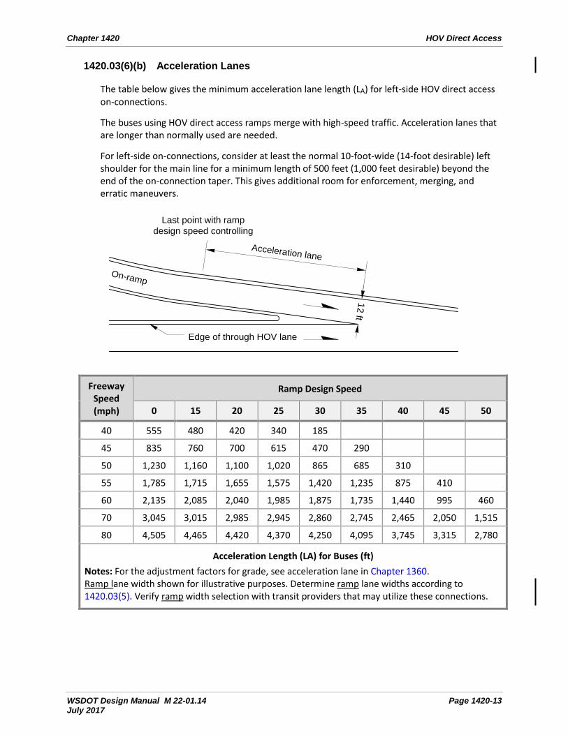
1420.03(6)(b) Acceleration Lanes
The table below gives the minimum acceleration lane length (LA) for left-side HOV direct access on-connections.
The buses using HOV direct access ramps merge with high-speed traffic. Acceleration lanes that are longer than normally used are needed.
For left-side on-connections, consider at least the normal 10-foot-wide (14-foot desirable) left shoulder for the main line for a minimum length of 500 feet (1,000 feet desirable) beyond the end of the on-connection taper. This gives additional room for enforcement, merging, and erratic maneuvers.
12 ft
Acceleration lane
On-ramp
Edge of through HOV lane
Last point with rampdesign speed controlling
Freeway Speed (mph)
Ramp Design Speed
0 15 20 25 30 35 40 45 50
40 555 480 420 340 185
45 835 760 700 615 470 290
50 1,230 1,160 1,100 1,020 865 685 310
55 1,785 1,715 1,655 1,575 1,420 1,235 875 410
60 2,135 2,085 2,040 1,985 1,875 1,735 1,440 995 460
70 3,045 3,015 2,985 2,945 2,860 2,745 2,465 2,050 1,515
80 4,505 4,465 4,420 4,370 4,250 4,095 3,745 3,315 2,780
Acceleration Length (LA) for Buses (ft) Notes: For the adjustment factors for grade, see acceleration lane in Chapter 1360. Ramp lane width shown for illustrative purposes. Determine ramp lane widths according to 1420.03(5). Verify ramp width selection with transit providers that may utilize these connections.
HOV Direct Access Chapter 1420
Page 1420-14 WSDOT Design Manual M 22-01.12 November 2015
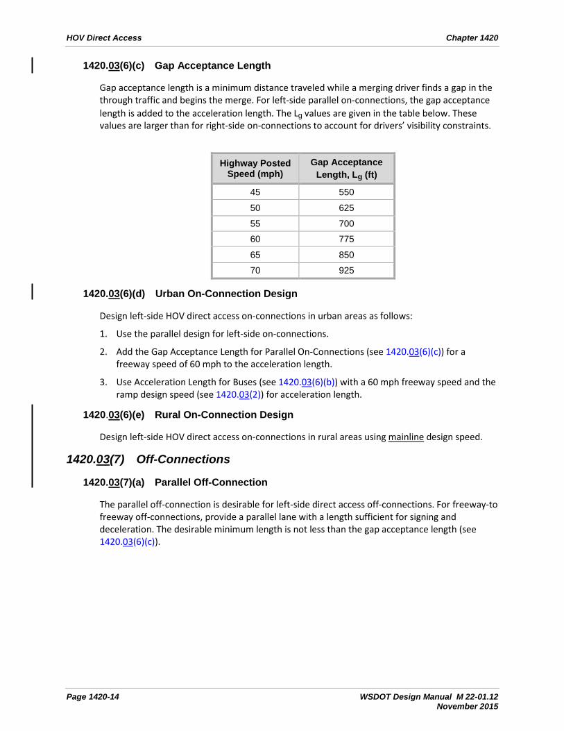
1420.03(6)(c) Gap Acceptance Length
Gap acceptance length is a minimum distance traveled while a merging driver finds a gap in the through traffic and begins the merge. For left-side parallel on-connections, the gap acceptance length is added to the acceleration length. The Lg values are given in the table below. These values are larger than for right-side on-connections to account for drivers’ visibility constraints.
Highway Posted Speed (mph)
Gap Acceptance Length, Lg (ft)
45 550
50 625
55 700
60 775
65 850
70 925
1420.03(6)(d) Urban On-Connection Design
Design left-side HOV direct access on-connections in urban areas as follows:
1. Use the parallel design for left-side on-connections.
2. Add the Gap Acceptance Length for Parallel On-Connections (see 1420.03(6)(c)) for a freeway speed of 60 mph to the acceleration length.
3. Use Acceleration Length for Buses (see 1420.03(6)(b)) with a 60 mph freeway speed and the ramp design speed (see 1420.03(2)) for acceleration length.
1420.03(6)(e) Rural On-Connection Design
Design left-side HOV direct access on-connections in rural areas using mainline design speed.
1420.03(7) Off-Connections
1420.03(7)(a) Parallel Off-Connection
The parallel off-connection is desirable for left-side direct access off-connections. For freeway-to freeway off-connections, provide a parallel lane with a length sufficient for signing and deceleration. The desirable minimum length is not less than the gap acceptance length (see 1420.03(6)(c)).

Chapter 1420 HOV Direct Access
WSDOT Design Manual M 22-01.14 Page 1420-15 July 2017
A [2]
12 ft
Edge of shoulder
Edge of through HOV lane
250 ft Deceleration lane LD [1]
See note [4]
90°[5]
PC of ramp curve Begin of ramp stationing
See Paving Detail
See note [6]
See note [3]
Notes:
[1] For deceleration lane length LD, see 1420.03(7)(c). Check LD for each ramp design speed.
[2] Point is the point controlling the ramp design speed or the end of the transit stop zone or other stopping point.
[3] Ramp lane width shown for illustrative purposes. Determine lane and shoulder widths according to 1420.03(5). Verify ramp width selection with transit providers that may utilize these connections.
[4] For ramp shoulder width, see 1420.03(5)(b).
[5] Angle point for width transitions, when required. (See Chapter 1210 for pavement transitions.)
[6] Gore area characteristics at drop ramp connections are shown on 1420.02(3)(a). (See Chapter 1360 for gore details at other connection types.)
[7] The desirable shoulder width is 10 ft.
General: For striping, see the Standard Plans.
1420.03(7)(b) Tapered Off-Connection
The tapered off-connection may be used, with justification. (See Chapter 1360 for the design of tapered off-connections.)
1420.03(7)(c) Deceleration Lanes
Bus passenger comfort requires longer deceleration lanes. Use the deceleration lane lengths from the table below for HOV direct access facilities.
2 ft
[7]
A

HOV Direct Access Chapter 1420
Page 1420-16 WSDOT Design Manual M 22-01.14 July 2017
12 ft
Deceleration lane
Off-ramp
Edge of through HOV lane
First point with rampdesign speed controlling
Freeway Speed (mph)
Ramp Design Speed
0 15 20 25 30 35 40 45 50
40 390 330 290 240 170 100
45 470 420 380 330 260 190 90
50 570 520 480 430 360 290 190 100
55 680 620 590 540 470 400 300 210 110
60 800 740 700 660 580 520 420 330 230
70 990 930 900 850 780 710 610 520 420
80 1,210 1,150 1,110 1,060 990 920 830 740 640
Deceleration Length (LD) for Buses (ft) Notes: For the adjustment factors for grade, see deceleration lane in Chapter 1360. Ramp lane width shown for illustrative purposes. Determine lane width according to 1420.03(5). Verify ramp width selection with transit providers that may utilize these connections.
1420.03(7)(d) Urban Off-Connection Design
Design left-side HOV direct access off-connections in urban areas as follows:
1. Either the parallel (desirable) or the taper (with justification) design may be used.
2. Use the longer deceleration length of: the Deceleration Length for Buses (see 1420.03(7)(c)) from a 60 mph freeway speed to the ramp design speed (see 1420.03(2)) or the Minimum Deceleration Length given in Chapter 1360 from the freeway design speed to the ramp design speed.
1420.03(7)(e) Rural Off-Connection Design
Design left-side HOV direct access off-connections in rural areas using mainline design speed.

Chapter 1420 HOV Direct Access
WSDOT Design Manual M 22-01.12 Page 1420-17 November 2015
1420.03(8) Vertical Clearance
Vertical clearance for a structure over a road is measured from the lower roadway surface, including the usable shoulders, to the bottom of the overhead structure.
Refer to Chapter 720 for information on vertical clearance.
The minimum vertical clearance for a pedestrian grade separation over any road is 17.5 feet.
1420.03(9) Flyer Stops
Design flyer-stop ramp on-connections as given in 1420.03(6), and design off-connections as given in 1420.03(7). Flyer stop connections are included in the access point spacing discussed in 1420.02(1)(a).
Design the ramp to the flyer stop in accordance with 1420.03(3), 1420.03(4), and 1420.03(5).
The minimum width for the roadway at a flyer stop is 24 feet.
When a flyer stop is in the median, provide enough median width for the flyer stop roadway, passenger facilities, and barrier separation without reducing the width of the through lanes or shoulders (see 1420.04).
The approval of a flyer stop requires the operational analysis portion of the interchange justification report (see Chapter 550).
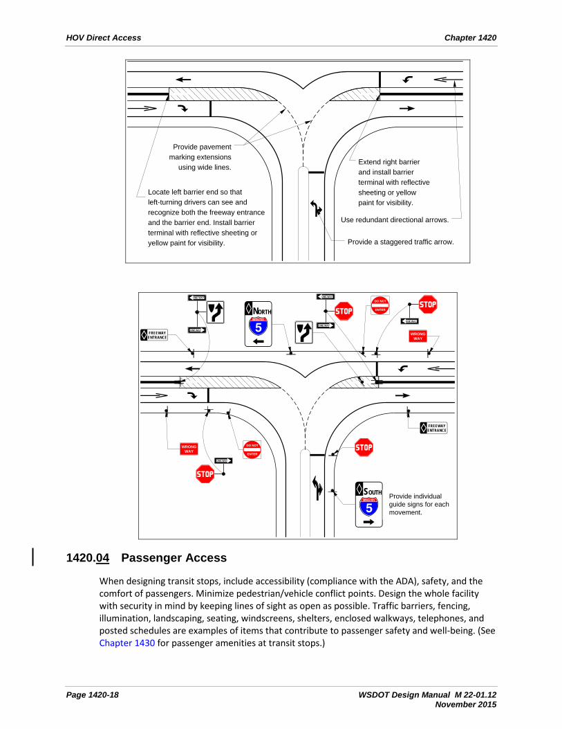
1420.03(10) Wrong-Way Driving Countermeasures
The following bulleted items and examples are countermeasures for wrong-way driving at HOV direct access ramps: • Provide a staggered traffic arrow to better describe the left and right turns. • Provide pavement marking extensions, using wide lines, through intersections. • Use redundant directional pavement arrows at ramp terminals. • Paint or use reflective sheeting to highlight barrier terminals. • Locate the left barrier end to provide good visibility for left-turning traffic for both the
barrier terminal and the on-ramp roadway. • Extend the right barrier as far as feasible while providing a 4-foot clearance for the left-
turning exiting design vehicle. • Provide redundant signing. • Provide enlarged warning signs.
HOV Direct Access Chapter 1420
Page 1420-18 WSDOT Design Manual M 22-01.12 November 2015
Locate left barrier end so that left-turning drivers can see and recognize both the freeway entrance and the barrier end. Install barrier terminal with reflective sheeting or yellow paint for visibility.
Extend right barrier and install barrier terminal with reflective sheeting or yellow paint for visibility.
Provide pavement marking extensions
using wide lines.
Provide a staggered traffic arrow.
Use redundant directional arrows.
FREEWAYENTRANCE
INTERSTATE
SOUTH
INTERSTATE
NORTH
FREEWAYENTRANCE
WRONGWAY
WRONGWAY
ONE WAY
ONE WAY
Provide individual guide signs for each movement.
ONE WAY
ONE WAY
DO NOT
ENTER
ONE WAY
ONE WAY
DO NOT
ENTER
1420.04 Passenger Access
When designing transit stops, include accessibility (compliance with the ADA), safety, and the comfort of passengers. Minimize pedestrian/vehicle conflict points. Design the whole facility with security in mind by keeping lines of sight as open as possible. Traffic barriers, fencing, illumination, landscaping, seating, windscreens, shelters, enclosed walkways, telephones, and posted schedules are examples of items that contribute to passenger safety and well-being. (See Chapter 1430 for passenger amenities at transit stops.)

Chapter 1420 HOV Direct Access
WSDOT Design Manual M 22-01.12 Page 1420-19 November 2015
1420.04(1) Passengers To encourage use of the passenger access facility for an express transit stop, provide a route that is the shortest distance to travel from the park & ride lot or local transit stop. Failure to do so might generate the use of undesirable shortcuts. To encourage local use of the passenger access facilities, provide direct access from surrounding neighborhoods.
Provide grade separations for pedestrian access to transit stops in the median. Consider stairways, ramps, elevators, and escalators, but provide at least one access for the disabled at every loading platform, as required by the American with Disabilities Act of 1990. (See Chapter 1510 for guidance when designing pedestrian grade separations.)
The ADA Accessibility Guidelines for Buildings and Facilities states, “Platform edges bordering a drop-off and not protected by platform screens or guard rails shall have a detectable warning … 24 inches wide running the full length of the platform drop-off.” (See the Standard Plans for the detectable warning pattern.)
At transit stops, at-grade crosswalks are only permitted in the at-grade crossing flyer stop layout described in 1420.02(4)(a)2. Use traffic calming techniques, such as horizontal alignment, textured pavement and crosswalk markings, barrier openings, and other treatments, to channelize pedestrian movements and slow the transit vehicle’s movements. Illuminate transit stop crosswalks (see Chapter 1040).
Where at-grade crosswalks are not permitted, take steps to minimize unauthorized at-grade crossings. Fencing, taller concrete traffic barrier, enclosed walkways, and ramps are examples of steps that may be taken.
1420.04(2) Bicycles Bike lanes on nearby streets and separate trails encourage people to bicycle from surrounding neighborhoods. Provide these bicyclists direct access to passenger access facilities.
Design bicycle access facilities in conjunction with the access for the disabled (see Chapters 1510, 1515, and 1520).
Locate bicycle parking outside of the passenger walkways (see Chapter 1430).
Locations near colleges and universities and locations with good bicycle access, especially near trails, will attract bicyclists. Contact the region Bicycle Coordinator for information on the predicted number of bicycle parking spaces needed and the types of bicycle racks available.
1420.05 Traffic Design Elements Traffic design elements are critical to the safe and efficient use of HOV direct access facilities. The following discusses the elements of traffic design that might be different for HOV direct access facilities.
1420.05(1) Traffic Barriers Separate the main line from the HOV direct access facilities with a traffic barrier. Whenever possible, separate opposing traffic lanes in the facility by using traffic barrier (see Chapter 1610). This is especially important in areas where opposing traffic is changing speeds to or from main line speeds. Concrete barrier is generally desirable on these facilities due to lower maintenance requirements.

HOV Direct Access Chapter 1420
Page 1420-20 WSDOT Design Manual M 22-01.12 November 2015
Provide crashworthy end treatments to the approach ends of traffic barriers (see Chapter 1620).
When the operating speed is 25 mph or lower, and where an at-grade pedestrian crossing transit stop has an opening in a concrete barrier, a sloped-down end as shown in the Standard Plans is acceptable.
When providing a break in the barrier for turning maneuvers, consider sight distance (see Chapter 1260) when determining the location for stopping the barrier.
In areas where headlight glare is a concern, consider glare screens such as taller concrete barrier. Other glare screen options that mount on the top of a barrier tend to be high-maintenance items and are discouraged.
Taller barrier might also be desirable in areas where pedestrian access is discouraged, such as between opposing flyer stops or between a flyer stop and the main line.
1420.05(2) Signing
Design and place HOV signing to clearly indicate whether the signs are intended for motorists in the HOV lane or the general-purpose lanes. The purposes of the signs are to: • Enhance safety. • Convey the message that HOV lanes are restricted to HOVs. • Provide clear directions for entrances and exits. • Define vehicle occupancy requirements or other restrictions.
Because HOV facilities are not found in many regions, the signing not only considers the commuter but also the occasional user of the facility who might be unfamiliar with the HOV facility and its operation.
1420.05(2)(a) Safety
Much of HOV signing relates to enhancing safety for motorists. Not only are geometrics often minimized due to the lack of right of way, but there are unusual operational characteristics such as the differential speed between the HOV vehicle and the adjacent general-purpose traffic. To allow for the lack of passing opportunities in the HOV lane and the necessity for frequent merging and weaving actions, use messages that are clear and concise, and use symbols wherever possible.
Because left-side off-connections are unusual, advance warning signing alerting motorists that an exit is on the left becomes more important.
For T ramps, provide traffic control at the T to assign priority to one of the turn movements and to avert wrong-way movements.

Chapter 1420 HOV Direct Access
WSDOT Design Manual M 22-01.12 Page 1420-21 November 2015
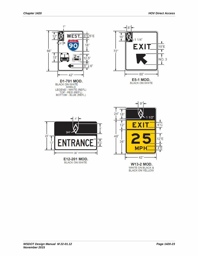
1420.05(2)(b) Diamond Symbols
The diamond symbol is used to designate HOV facilities where carpools are allowed. For all signs, whether regulatory, guide, or warning, the symbol is white on a black background to convey the restrictive nature of the HOV lane and to make the signs more uniformly recognizable. The use of the symbol with all HOV signs also informs drivers that the message is intended for HOVs. The diamond symbol is only for HOV lanes where carpools are allowed; it is not used for bus, taxi, or bicycle preferential lanes.
1420.05(2)(c) Selection and Location
The signing details given throughout this section provide for the HOV geometric configurations used within the right of way. Signing for other types of HOV facilities (such as those used for reversible-flow and for HOV direct access between freeways and temporary HOV lanes used during construction) is designed on a case-by-case basis and requires consultation with the appropriate Headquarters and region traffic personnel. In addition to the normal regulatory signs, include HOV guide signs, both advance and action, in the design of signing for HOV direct access between freeways.
Notes: • Place signs in accordance with the MUTCD. • For non-HOV sign details, see the Sign Fabrication Manual.

HOV Direct Access Chapter 1420
Page 1420-22 WSDOT Design Manual M 22-01.12 November 2015
1420.05(2)(d) Regulatory Signs
Regulatory signs for HOV facilities follow the normal regulatory signing principles: black legend with a white reflective background on a rectangular panel. Keep in mind that messages conveyed by the HOV signs (such as signs concerning violations and those indicating the beginning of an HOV lane downstream) are not necessarily intended only for the HOV vehicle. Therefore, it might be prudent to place additional signs on the right side of the freeway when doing so conforms to sound engineering practice.
Chapter 1420 HOV Direct Access
WSDOT Design Manual M 22-01.12 Page 1420-23 November 2015
HOV Direct Access Chapter 1420
Page 1420-24 WSDOT Design Manual M 22-01.12 November 2015
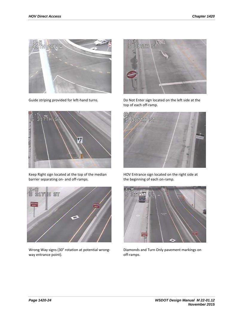
Guide striping provided for left-hand turns.
Do Not Enter sign located on the left side at the top of each off-ramp.
Keep Right sign located at the top of the median barrier separating on- and off-ramps.
HOV Entrance sign located on the right side at the beginning of each on-ramp.
Wrong Way signs (30° rotation at potential wrong-way entrance point).
Diamonds and Turn Only pavement markings on off-ramps.
Chapter 1420 HOV Direct Access
WSDOT Design Manual M 22-01.12 Page 1420-25 November 2015
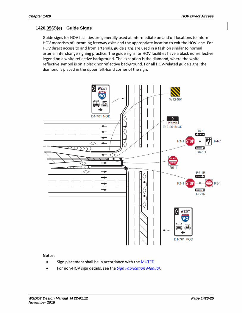
1420.05(2)(e) Guide Signs
Guide signs for HOV facilities are generally used at intermediate on and off locations to inform HOV motorists of upcoming freeway exits and the appropriate location to exit the HOV lane. For HOV direct access to and from arterials, guide signs are used in a fashion similar to normal arterial interchange signing practice. The guide signs for HOV facilities have a black nonreflective legend on a white reflective background. The exception is the diamond, where the white reflective symbol is on a black nonreflective background. For all HOV-related guide signs, the diamond is placed in the upper left-hand corner of the sign.
Notes: • Sign placement shall be in accordance with the MUTCD. • For non-HOV sign details, see the Sign Fabrication Manual.

HOV Direct Access Chapter 1420
Page 1420-26 WSDOT Design Manual M 22-01.12 November 2015
1420.05(3) Lighting
Provide illumination of HOV direct access ramps, loading platforms at transit stops, major parking lots, and walkways as defined in Chapter 1040.
1420.05(4) Intelligent Transportation Systems
Intelligent Transportation Systems (ITS) are used to collect traffic data, maintain freeway flow, and disseminate traveler information. Transit information systems for passengers and transit facility surveillance are not normally a part of WSDOT’s system, but implementation of these components may be considered for some locations.
Fully utilize available ITS elements in the design of HOV direct access facilities. Need for ITS elements varies depending on project features, such as facility design and operation, and whether the site has existing ITS components.
ITS elements that might be applicable to HOV direct access facilities include: closed circuit television surveillance; ramp metering; data collection; exit queue detection and override; dynamic signing; transit signal priority; and automatic vehicle identification and location.
Guidance on the development of ITS elements is found in Chapter 1050. Include the region Traffic Office, transit operator, and affected local agency in the coordination for the design and implementation of ITS.
1420.06 Documentation Refer to Chapter 300 for design documentation requirements.
1420.07 References
1420.07(1) Federal/State Laws and Codes Americans with Disabilities Act of 1990 (ADA) (28 Code of Federal Regulations [CFR] Part 36, Appendix A, as revised July 1, 1994)
Washington Administrative Code (WAC) 468-510-010, High occupancy vehicles (HOV)
1420.07(2) Design Guidance ADA Field Guide for Accessible Public Rights of Way, WSDOT
ADA Standards for Accessible Design, U.S. Department of Justice (USDOJ), 2010; consists of 28 CFR parts 35 & 36 and the ADA and Architectural Barriers Act (ABA) Accessibility Guidelines for Buildings and Facilities (ADA-ABAAG; also referred to as the 2004 ADAAG), July 23, 2004, U.S.
Access Board. (For buildings and on-site facilities; applies to new construction or alterations as of March 15, 2012.) www.access-board.gov/guidelines-and-standards
ADA Standards for Transportation Facilities, USDOT, 2006; consists of 49 CFR Parts 37 & 38 and the ADA and ABA Accessibility Guidelines for Buildings and Facilities (ADA-ABAAG; also referred to as the 2004 ADAAG), July 23, 2004, U.S. Access Board as modified by USDOT. (For transit, light rail, and similar public transportation facilities.) www.access-board.gov/guidelines-and-standards
Chapter 1420 HOV Direct Access
WSDOT Design Manual M 22-01.12 Page 1420-27 November 2015
Manual on Uniform Traffic Control Devices for Streets and Highways, USDOT, FHWA; as adopted and modified by Chapter 468-95 WAC “Manual on uniform traffic control devices for streets and highways” (MUTCD)
Revised Draft Guidelines for Accessible Public Rights-of-Way (PROWAG), November 23, 2005, U.S. Access Board. The current best practices for evaluation and design of pedestrian facilities in the public right of way per the following FHWA memoranda: www.fhwa.dot.gov/environment/bikeped/prwaa.htm www.fhwa.dot.gov/civilrights/memos/ada_memo_clarificationa.htm http://www.access-board.gov/guidelines-and-standards
Sign Fabrication Manual, M 55-05, WSDOT
Standard Plans for Road, Bridge, and Municipal Construction (Standard Plans), M 21-01, WSDOT
1420.07(3) Supporting Information
A Policy on Geometric Design of Highways and Streets (Green Book), AASHTO
FHWA/PB, HOV Interactive 1.0 High Occupancy Vehicle Data Base from the U.S., Canada and Europe (CD ROM), USDOT, FHWA and Parsons Brinkerhoff
Bus Use of Highways: Planning and Design Guidelines, NCHRP 155
Guide for the Design of High-Occupancy Vehicle (HOV) Facilities, AASHTO
High-Occupancy Vehicle Facilities: A Planning, Design, and Operation Manual, Parsons Brinckerhoff
HOV Systems Manual, NCHRP 414
“Transit Implications of HOV Facility Design,” WA-RD 396.1, September 1996, WSDOT and USDOT, Federal Transit Administration

HOV Direct Access Chapter 1420
Page 1420-28 WSDOT Design Manual M 22-01.12 November 2015