Embed Size (px)
Citation preview

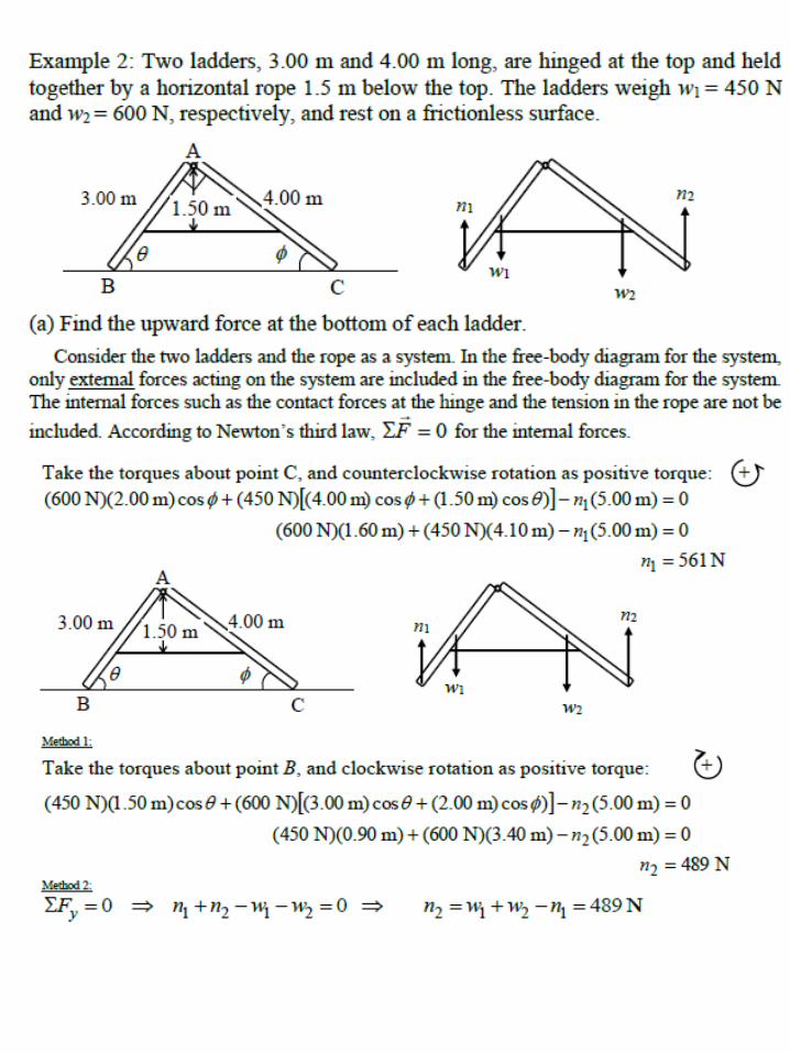
Chapter 12
Static Equilibrium12.1 Analysis Model: Rigid Body in
Equilibrium
12.2 More on the Center of Gravity
12.3 Examples of Rigid Objects in Static
Equilibrium

CHAPTER 12 : STATIC EQUILIBRIUM AND
ELASTICITY
12.1) The Conditions For Equilibrium
Object treated as a particle
• One necessary condition for equilibrium = the net force
acting on an object is zero.
For extended object
• The net force acting on an object is zero.
• Involves the net torque acting on the extended object.
• Equilibrium does not require the absence of motion.
• A rotating object can have constant angular velocity and still
be in equilibrium.
• Consider a single force F acting on a rigid object
(Figure (12.1)).
• The effect of the force depends on its point of application P.
• If r is the position vector of this point relative to O, the torque
assiciated with the force F about O is given by Equation
(11.7) :
Frτ

• From vector product (Section (11.2)) – the vector is
perpendicular to the plane formed by r and F.
• Right-hand rule – to determine the direction of : Curl
the fingers of your right hand in the direction of rotation
that F tends to cause about an axis through O, your
thumb then points in the direction of .
• In Figure (12.1) - is directed toward out of the page.
• From Figure (12.1) – the tendency of F to rotate the
object about an axis through O depends on the moment
arm d and the magnitude of F.
• Magnitude of = Fd (Eq. (10.19).
• Suppose a rigid object is acted on first by force F1 and
later by force F2.
• If the two forces have the same magnitude – they will
produce the same effect on the object only if they have
the same direction and the same line of action.
• Equivalent forces = two forces F1 and F2 are equivalent if
and only if F1 = F2 and if and only if the two produce
the same torque about any axis.

• Figure (12.2) – two forces are equal in magnitude and
opposite in direction = not equivalent.
• The force directed to the right tends to rotate the object
clockwise about an axis perpendicular to the diagram
through O.
• The force dircted to the left tends to rotate it
counterclockwise about that axis.
• Figure (12.3) – an object is pivoted about an axis through its
center of mass.
• Two forces of equal magnitude act in opposite directions
along parallel lines of action.
• A pair of forces acting in this manner = couple
• Because each force produces the same torque Fd, the net
torque has a magnitude of 2Fd.
F1
F2
O
Figure (12.2)

• The object rotates clockwise and undergoes an angular
acceleration about the axis = nonequilibrium situation
(with respect to rotational motion).
• The net torque on the object gives rise to an angular
acceleration according to the relationship = 2Fd = I
(Eq. (10.21)).
• An object is in rotational equilibrium only if its angular
acceleration = 0.
• Because = I for rotation about a fixed axis, the net
torque about any axis must be zero.
Two necessary conditions for equilibrium of an object :
1. The resultant external force must equal zero.
F = 0 (12.1)
2. The resultant external torque about any axis must be
zero. = 0 (12.2)
3. Special case of static equilibrium – the object is at rest and
so has no linear or angular speed (that is, vCM = 0 and
= 0).
Translational equilibrium – tells us that the linear
acceleration of the center of mass of the object must be
zero when viewed from an inertial reference frame.
Rotational equilibrium and tells us that the
angular acceleration about any axis must be
zero.

• From equation (12.1) and (12.2) – equivalent to six scalar
equations (Fx , Fy , Fz , x , y , z ).
• Restrict to situations in which all the forces lie in the xy
plane.
• Forces whose vector representations are in the same plane are
said to be coplanar.
• Deal with only three scalar equations.
• Two of these come from balancing the forces in the x and y
direction (Fx , Fy).
• The third comes from the torque equation – the net torque
about any point in the xy plane must be zero.
• Hence, the two conditions of equilibrium provde the
equations :
where the axis of the torque equation is arbitrary.
• Regardless of the number of forces that are acting – if an
object is in translational equilibrium and if the net torque is
zero about one axis, then the net torque must also be zero
about any other axis.
• The point can be inside or outside the boundaries of the
object.
Fx = 0 Fy = 0 z = 0 (12.3)

• Consider an object being acted on by several forces such
that the resultant force F = F1 + F2 + F3 + … = 0.
• Figure (12.4) – four forces acted on the object.
• The point of application of F1 relative to O is specified by
the position vector r1.
• Similarly, the points of application of F2 , F3 , … are
specified by r2 , r3 , ….
• The net torque about an axis through O is :
F2
F1
F3F4
O
r1
r’ O’
r1 – r’ Figure (12.4)
...332211O FrFrFrτ

• Now consider another arbitrary point O’ having a posiiton
vector r’ relative to O.
• The point of application of F1 relative to O’ is identified by
the vector r1 – r’.
• The point of application of F2 relative to O’ is r2 – r’ , and
so forth.
• Therefore, the torque about an axis through O’ is :
• Because the net force is assumed to be zero (given that the
object is in translational equilibrium), the last term
vanishes, and we see that the torque about O’ is equal to the
torque about O.
• Hence, if an object is in translational equilibrium and the
net torque is zero about one point, then the net torque must
be zero about any other point.
...)( '...
...)'()'()'(
321332211
332211'O
FFFrFrFrFr
FrrFrrFrrτ

12.2) More on the Center of Gravity
• Whenever deal with a rigid object – consider (1) the force
of gravity acting on it, and (2) the point of application of
this force.
• On every object is a special point = center of gravity.
• All the various gravitational forces acting on all the various
mass elements of the object are equivalent to a single
gravitational force acting through this point.
• To compute the torque due to the gravitational force on an
object of mass M – consider the force Mg acting at the
center of gravity of the object.
To find this special point (center of gravity)
• If we assume that g is uniform over the object – the center
of gravity of the object coincides with its center of mass.
• Consider an object of arbitrary shape lying in the xy plane
(Figure (12.5)).
• Suppose the object is divided into a large number of
particles of masses m1 , m2 , m3 , … having coordinates
(x1 , y1), (x2 , y2), (x3 , y3), ….
• In Equation (9.28) – the x coordinate of the center of mass
of such an object :
ii
iii
n321
nn332211CM
m
xm
m...mmm
xm...xmxmxmx
Similar form of equation to define the
y coordinate of the center of mass.

• Figure (12.6) – consider the force of gravity exerted on each
particle.
• Each particle contributes a torque about the origin equal in
magnitude to the particle’s weight mg multiplied by its
moment arm.
• Example – the torque due to the force m1g1 is m1g1x1 , where
g1 is the magnitude of the gravitational field at the position of
the particle of mass m1.
• Locate the center of gravity, the point at which application of
the single gravitational force Mg (where M = m1 + m2 + m3 +
… is the total mass of the object) has the same effect on
rotation as does the combined effect of all the individual
gravitational forces migi .
• Equating the torque resulting from Mg acting at the center of
gravity to the sum of the torques acting on the individual
particles gives :
• If we assume uniform g over the object – then the g terms
cancel and we obtain :
...xgm
xgmxgmx...gmgmgm
333
222111CG332211
...mmm
...xmxmxmx
321
332211CG
(12.4)
The center of gravity is located at the center of mass as
long as the object is in a uniform gravitational field.
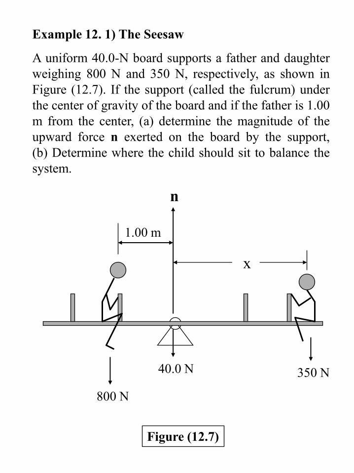
Example 12. 1) The Seesaw
A uniform 40.0-N board supports a father and daughter
weighing 800 N and 350 N, respectively, as shown in
Figure (12.7). If the support (called the fulcrum) under
the center of gravity of the board and if the father is 1.00
m from the center, (a) determine the magnitude of the
upward force n exerted on the board by the support,
(b) Determine where the child should sit to balance the
system.
x
n
1.00 m
350 N
800 N
40.0 N
Figure (12.7)
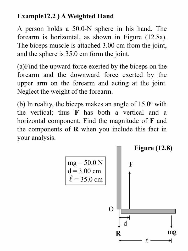
Example12.2 ) A Weighted Hand
A person holds a 50.0-N sphere in his hand. The
forearm is horizontal, as shown in Figure (12.8a).
The biceps muscle is attached 3.00 cm from the joint,
and the sphere is 35.0 cm form the joint.
(a)Find the upward force exerted by the biceps on the
forearm and the downward force exerted by the
upper arm on the forearm and acting at the joint.
Neglect the weight of the forearm.
(b) In reality, the biceps makes an angle of 15.0o with
the vertical; thus F has both a vertical and a
horizontal component. Find the magnitude of F and
the components of R when you include this fact in
your analysis.
d
O
R
F
mg
mg = 50.0 N
d = 3.00 cm
= 35.0 cm
Figure (12.8)
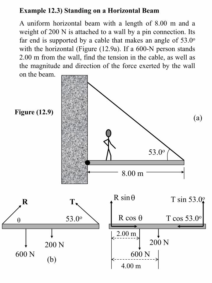
Example 12.3) Standing on a Horizontal Beam
A uniform horizontal beam with a length of 8.00 m and a
weight of 200 N is attached to a wall by a pin connection. Its
far end is supported by a cable that makes an angle of 53.0o
with the horizontal (Figure (12.9a). If a 600-N person stands
2.00 m from the wall, find the tension in the cable, as well as
the magnitude and direction of the force exerted by the wall
on the beam.
8.00 m
53.0o
(a)
53.0o
R T
200 N
600 N(b)
200 N
600 N
2.00 m
4.00 m
R sin
R cos
T sin 53.0o
T cos 53.0o
Figure (12.9)

Example 12.4) The Leaning Ladder
A uniform ladder of length and weight mg = 50 N
rests against a smooth, vertical wall (Figure (12.10a). If
the coefficient of static friction between the ladder and
the grond is s = 0.40, find the minimum angle min at
which the ladder does not slip.
(a)
O
O’
P
n R
f
mg
(b)
Figure (12.10)