Embed Size (px)
Citation preview

Essential Software Development
© David Dawson and Adrian Janson Cambridge University Press 1
CHAPTER 12 SOLUTIONS
Hardware Design Project 1 – Aeroplane Landing Device
1 An aeroplane is fitted with an automatic landing device which is still in the
experimental stage and uses a lot of fuel. Whether the captain uses it or not
depends on three factors:
i fog conditions
ii whether he is carrying passengers
iii whether he has sufficient fuel.
If the runway is foggy and he has enough fuel, he will use it. He can afford to use
it in fog even if he has very little fuel as long as he has no passengers on board.
He will also use it (for practise) even if it is clear, providing he has sufficient fuel
and no passengers.
In all other conditions he will land manually.
Design a logic circuit which decides whether the captain should land manually or
on automatic. Your circuit should have three inputs:
i Fog (1) / No Fog (0)
ii Passengers (1) / No Passengers (0)
iii Enough Fuel (1) / Not Enough Fuel (0)
and one output:
Auto (1) / Manual (0)
Minimise the number of gates, where possible.
Hand in all your working out and the final circuit design. Please include written
explanations along with this, and tests on the circuit to ensure that it behaves
correctly.
Answer F: Fog (1), No Fog (0)
P: Passengers (1), No Passengers (0)
E: Enough Fuel (1), Not Enough Fuel (0)
X: Auto (1), Manual (0)
F P E X
0 0 0 0
0 0 1 1
0 1 0 0
0 1 1 0
1 0 0 1
1 0 1 1
1 1 0 0
1 1 1 1

Essential Software Development
© David Dawson and Adrian Janson Cambridge University Press 2
Logic Statement: (F AND E) OR (F AND NOT P) OR (E AND NOT P)
2 The minimum number of binary digits used to represent one decimal digit is 4
(some are redundant). It is intended to display each decimal digit in an LCD
display, and select each element of the display depending of the position of four
switches (each switch representing one binary digit). The LCD display looks like
the diagram below:
E (1)
E (0)
F (1) F (1)
P (1) P (0)
1
1
1 1 0
0 0 0
F (0)
P
F
E
X
Essential Software Development
© David Dawson and Adrian Janson Cambridge University Press 3
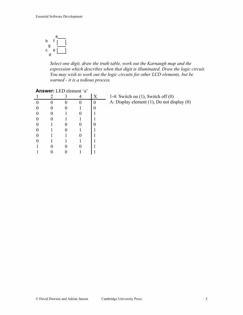
a b f g c e d
Select one digit, draw the truth table, work out the Karnaugh map and the
expression which describes when that digit is illuminated. Draw the logic circuit.
You may wish to work out the logic circuits for other LCD elements, but be
warned - it is a tedious process.
Answer: LED element ‘a’
1-4: Switch on (1), Switch off (0)
A: Display element (1), Do not display (0)
1 2 3 4 X
0 0 0 0 0
0 0 0 1 0
0 0 1 0 1
0 0 1 1 1
0 1 0 0 0
0 1 0 1 1
0 1 1 0 1
0 1 1 1 1
1 0 0 0 1
1 0 0 1 1

Essential Software Development
© David Dawson and Adrian Janson Cambridge University Press 4
Logic Statement: 1 OR 3 OR (2 AND 4)
3 (1)
3 (0)
1 (1) 1 (1)
2 (1) 2 (0)
0
1
0
1
4 (1)
4 (0)
4 (0)
1 (0)
0
1 1 1
1
1
1 1 1
1 1
1
2
4
1 X
3
Essential Software Development
© David Dawson and Adrian Janson Cambridge University Press 5
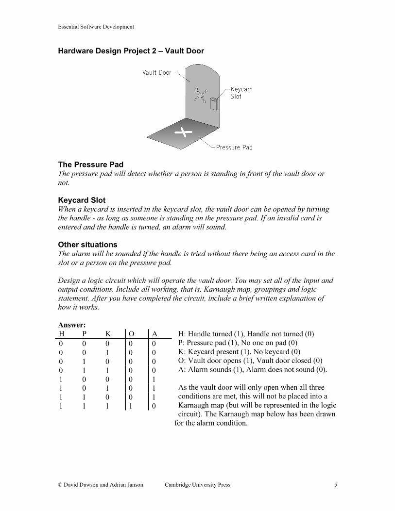
Hardware Design Project 2 – Vault Door
The Pressure Pad The pressure pad will detect whether a person is standing in front of the vault door or
not.
Keycard Slot When a keycard is inserted in the keycard slot, the vault door can be opened by turning
the handle - as long as someone is standing on the pressure pad. If an invalid card is
entered and the handle is turned, an alarm will sound.
Other situations The alarm will be sounded if the handle is tried without there being an access card in the
slot or a person on the pressure pad.
Design a logic circuit which will operate the vault door. You may set all of the input and
output conditions. Include all working, that is, Karnaugh map, groupings and logic
statement. After you have completed the circuit, include a brief written explanation of
how it works.
Answer:
H: Handle turned (1), Handle not turned (0)
P: Pressure pad (1), No one on pad (0)
K: Keycard present (1), No keycard (0)
O: Vault door opens (1), Vault door closed (0)
A: Alarm sounds (1), Alarm does not sound (0).
As the vault door will only open when all three
conditions are met, this will not be placed into a
Karnaugh map (but will be represented in the logic
circuit). The Karnaugh map below has been drawn
for the alarm condition.
H P K O A
0 0 0 0 0
0 0 1 0 0
0 1 0 0 0
0 1 1 0 0
1 0 0 0 1
1 0 1 0 1
1 1 0 0 1
1 1 1 1 0

Essential Software Development
© David Dawson and Adrian Janson Cambridge University Press 6
Logic Statement: (H AND NOT P) OR (H AND NOT K)
P (1)
P (0)
H (1) H (1)
K (1) K (0)
0
1
1 0 0
1 0 0
H (0)
P
H
K
A
O
Essential Software Development
© David Dawson and Adrian Janson Cambridge University Press 7
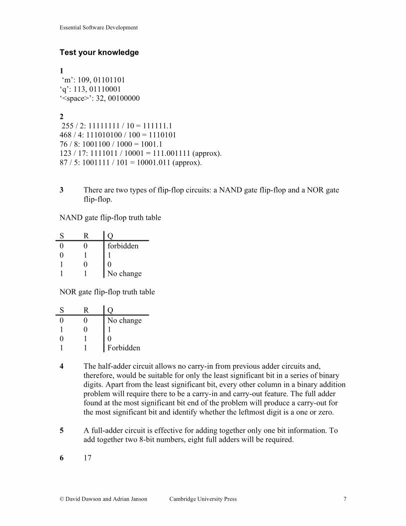
Test your knowledge
1
‘m’: 109, 01101101
‘q’: 113, 01110001
‘<space>’: 32, 00100000
2
255 / 2: 11111111 / 10 = 111111.1
468 / 4: 111010100 / 100 = 1110101
76 / 8: 1001100 / 1000 = 1001.1
123 / 17: 1111011 / 10001 = 111.001111 (approx).
87 / 5: 1001111 / 101 = 10001.011 (approx).
3 There are two types of flip-flop circuits: a NAND gate flip-flop and a NOR gate
flip-flop.
NAND gate flip-flop truth table
S R Q
0 0 forbidden
0 1 1
1 0 0
1 1 No change
NOR gate flip-flop truth table
S R Q
0 0 No change
1 0 1
0 1 0
1 1 Forbidden
4 The half-adder circuit allows no carry-in from previous adder circuits and,
therefore, would be suitable for only the least significant bit in a series of binary
digits. Apart from the least significant bit, every other column in a binary addition
problem will require there to be a carry-in and carry-out feature. The full adder
found at the most significant bit end of the problem will produce a carry-out for
the most significant bit and identify whether the leftmost digit is a one or zero.
5 A full-adder circuit is effective for adding together only one bit information. To
add together two 8-bit numbers, eight full adders will be required.
6 17
Essential Software Development
© David Dawson and Adrian Janson Cambridge University Press 8
7 a ASCII control characters are not used in modern printers.
b A control stream is a structure of control characters that imparts information
such as the start of the transmission, end of the transmission and often a check bit.
c An escape sequence is a sequence of ASCII control characters beginning with
character ‘27’. It was used to output a number of commands directly to the printer
within the stream of characters that it was printing. The control characters were
not printed, but caused particular commands to be carried out.
8 Binary addition is a simple matter for two’s complement numbers. Once they
have been changed to two’s complement, the numbers can simply be added
together as two binary numbers normally would be.
9 Binary subtraction is a simple matter in two’s complement numbers. Once the
number to be subtracted is translated into two’s complement, the numbers can be
added together as for any two binary numbers.
10 Binary multiplication takes place in a very similar fashion to that of decimal
multiplication. As each digit is multiplied, if the multiplier is a 0 then the result is
a line of bits of 0 value. If the multiplier is a 1 then the multiplicand is simply
written down below the multiplier. The partial products are then added together to
give the end result.
11 Binary division in two’s complement numbers involves a shift and subtract
method, much like long-division.
12 Single precision floating point.
13 Double-precision floating point.
14 Binary digits are calculated by using powers of 2 based on their position as shown
below.
Binary 1 1 1 1 1 1 1 1
Power
of two
2^7 2^6 2^5 2^4 2^3 2^2 2^1 2^0
Decimal 128 64 32 16 8 4 2 1
15 There are a number of shortcomings with sign-magnitude representation. Firstly,
if numbers are to be added or subtracted, the value of the leftmost bit will have to
be considered each time. It is even more inefficient since there are two
representations of zero.

Essential Software Development
© David Dawson and Adrian Janson Cambridge University Press 9
Extend your knowledge
1
75 + 39 = 01001011 +
00100111 =
01110010 (114)
139 + 59 = 010001011 +
000111011 =
011000100 (196)
123 + -56 = 01111011 +
11001000 =
01000011 (67)
15 + 7 = 00001111 +
00000111 =
00010110 (22)
-28 + 22 = 11100100 +
00010110 =
11111010 00000101 + 1 = 0000110 (-6)
2
Logic Statement: C OR (A AND B)
B (1)
B (0)
A (1) A (1)
C (1) C (0)
0
0
1 1 1
1 1 0
A (0)

Essential Software Development
© David Dawson and Adrian Janson Cambridge University Press 10
3
4
5
Draw an AND gate, and draw lines from A and B into it.
Take a line from C and put it through a NOT gate.
B T I X
0 0 0 0
0 0 1 0
0 1 0 0
0 1 1 1
1 0 0 1
1 0 1 1
1 1 0 1
1 1 1 1
O S L X
0 0 0 0
0 0 1 0
0 1 0 0
0 1 1 1
1 0 0 1
1 0 1 1
1 1 0 1
1 1 1 1
A
B
A
B
C
X

Essential Software Development
© David Dawson and Adrian Janson Cambridge University Press 11
Take another line from B and put it through another NOT gate.
Take both the outputs from the NOT gates and put them through another AND
gate.
Take the outputs from both of the AND gates and put them into an OR gate.
A
B
C
A
B
C
A
B
C

Essential Software Development
© David Dawson and Adrian Janson Cambridge University Press 12
The output from the OR gate, is X (refer to the truth table).
244 = 11110100
45 = 101101
17 = 10001
117 = 1110101
76 = 1001100
7
10010000 = 144
1000010 = 66
100101 = 37
1101101 = 109
111011 = 59
8
ABCDh = 1010101111001101
87FEh = 1000011111111110
9Dh = 10011101
BC9Ch = 1011110010011100
BAC7h = 1011101011000111
9
0101 0100 1110 0111 = 54E7
1111 0001 = F1
0110 1110 = 6E
0111 0001 1110 1101 = 71ED
0001 1111 1101 0110 = 1FD6
10
44h = 68
BEh = 190
65h = 101
A
B
C X

Essential Software Development
© David Dawson and Adrian Janson Cambridge University Press 13
E7h = 231
EBh = 235
11
241 = F1h
49 = 31h
171 = ABh
1117 = 45Dh
20376 = 4F98h
12
4 * 8 = 100 x 1000 = 100000 (32)
16 * 45 = 10000 x 101101 = 1011010000 (720)
23 * 16 = 10111 x 10000 = 101110000 (368)
255 * 8 = 11111111 x 1000 = 11111111000 (2040)
123 * 2 = 1111011 x 10 = 11110110 (246)
13
121 = 1111001
-34 = 1011101
59 = 111011
-251 = 100000100
199 = 11000111
14
123 + 45 = 1111011 +
101101 =
10101000 (168)
-49 + 33 = 1001110 +
100001 =
1101111 + 1 = 10010000 (-16)
136+ -29 = 10001000 +
11100010 =
??
233 + 67 = 11101001 +
1000011 =
100101100 (300)
-199 + -73 = 100111000 +
110110110 =
1011101110?? = 1100010000 (-272)


![He was known for his big laugh and even bigger talent Even when he was young] he loved to tell stories and play jokes, he loved singing and playing](https://img.dokumen.tips/doc/110x75/56649d2f5503460f94a07c52/he-was-known-for-his-big-laugh-and-even-bigger-talent-even-when-he-was-young.jpg)