Embed Size (px)
Citation preview

Topic #625-000-007 January 1, 2009 Plans Preparation Manual, Volume 1 - English Revised – January 1, 2012
Transportation Management Plan 10-i
Chapter 10
Transportation Management Plan
10.1 General ..................................................................................... 10-1
10.2 References ................................................................................ 10-2
10.2.1 Design Standards...................................................... 10-2
10.3 Transportation Management Plan (TMP) .................................. 10-3
10.3.1 Transportation Management Plan Components ....... 10-7
10.3.1.1 Temporary Traffic Control (TTC) Plans ..... 10-7
10.3.1.1.1 TTC Plan Development ........... 10-9
10.3.1.1.2 TTC Plan Phase Submittals ... 10-12
10.3.1.2 Transportation Operations (TO) .............. 10-13
10.3.1.3 Public Information (PI) ............................ 10-14
10.4 Coordination ............................................................................ 10-16
10.4.1 Coordination of TTC Plans with Structures Discipline ................................................................. 10-17
10.4.1.1 General ................................................... 10-17
10.4.1.2 Overhead Bridge Related Construction Activities .................................................. 10-17
10.4.1.3 Temporary Structures ............................. 10-18
10.4.1.4 General Coordination .............................. 10-19
10.5 Work Zone Traffic Control Training ......................................... 10-20
10.5.1 Background ............................................................. 10-20
10.5.2 Training Requirements ............................................ 10-20
10.6 Traffic Control Devices ............................................................ 10-21
10.7 Signs ....................................................................................... 10-22

Topic #625-000-007 January 1, 2009 Plans Preparation Manual, Volume 1 - English Revised – January 1, 2012
Transportation Management Plan 10-ii
10.7.1 Advance Warning Signs .......................................... 10-22
10.7.2 Length of Construction Sign .................................... 10-22
10.7.3 Project Information Sign .......................................... 10-22
10.7.4 Existing Signs ......................................................... 10-22
10.8 Lighting Units .......................................................................... 10-24
10.8.1 Warning Lights ........................................................ 10-24
10.8.2 Advance Warning Arrow Panels ............................. 10-24
10.8.3 Changeable Message Signs ................................... 10-25
10.8.4 Traffic Signals ......................................................... 10-30
10.9 Channelizing Devices .............................................................. 10-31
10.9.1 Type III Barricades .................................................. 10-31
10.9.2 Separation Devices ................................................. 10-31
10.9.3 Channelizing Device Alternates .............................. 10-31
10.10 Pavement Markings ................................................................ 10-32
10.10.1 Removing Pavement Markings ............................... 10-32
10.10.2 Raised Retro-Reflective Pavement Markers (RPM) ...................................................................... 10-32
10.10.3 Work Zone Markings ............................................... 10-32
10.11 Safety Appurtenances for Work Zones ................................... 10-33
10.11.1 Traffic Barriers ......................................................... 10-33
10.11.2 Barrier Walls (Temporary) ....................................... 10-33
10.11.3 End Treatments....................................................... 10-34
10.11.4 Modifications of Existing Barriers ............................ 10-34
10.11.5 Redirective Crash Cushions .................................... 10-35
10.12 Temporary Traffic Control Plan Details ................................... 10-36
10.12.1 Taper Lengths ......................................................... 10-36
10.12.2 Intersecting Road Signing and Signals ................... 10-37
10.12.3 Sight Distance to Delineation Devices .................... 10-38

Topic #625-000-007 January 1, 2009 Plans Preparation Manual, Volume 1 - English Revised – January 1, 2012
Transportation Management Plan 10-iii
10.12.4 Pedestrians and Bicyclists ...................................... 10-38
10.12.4.1 Pedestrian Considerations ...................... 10-38
10.12.4.2 Bicycle Considerations ............................ 10-39
10.12.5 Superelevation ........................................................ 10-39
10.12.6 Lane Widths ............................................................ 10-40
10.12.7 Lane Closure Analysis ............................................ 10-40
10.12.8 Traffic Pacing Design .............................................. 10-53
10.12.9 Detours, Diversions, and Lane Shifts ...................... 10-66
10.12.10 Above Ground Hazards ........................................... 10-67
10.12.11 Drop-offs in Work Zones ......................................... 10-67
10.12.12 Narrow Bridges and Roadways ............................... 10-67
10.12.13 Existing Highway Lighting ....................................... 10-68
10.12.14 Work Area Access ................................................... 10-68
10.12.15 Railroads ................................................................. 10-69
10.12.16 Temporary Raised Rumble Strip Sets ..................... 10-69
10.12.17 Pay Items and Quantities ........................................ 10-69
10.13 Speed Zoning .......................................................................... 10-71
10.13.1 Regulatory Speeds in Work Zones ......................... 10-71
10.14 Law Enforcement Services ..................................................... 10-73
10.14.1 Use of Speed and Law Enforcement Officers ......... 10-73
10.14.2 Use of Traffic Control Officer ................................... 10-74
10.14.3 Coordination, Documentation and Payment ........... 10-74
10.14.4 Other Uses of Law Enforcement ............................. 10-75
10.15 Motorist Awareness System (MAS) ......................................... 10-76
10.15.1 Portable Regulatory Signs (PRS) ............................ 10-76
10.15.2 Radar Speed Display Unit (RSDU) ......................... 10-77
10.15.3 Speed and Law Enforcement Officer ...................... 10-77

Topic #625-000-007 January 1, 2009 Plans Preparation Manual, Volume 1 - English Revised – January 1, 2012
Transportation Management Plan 10-iv
Tables Table 10.1 Common Bridge Related Overhead Work Activities
Requiring the Removal of Traffic Below .................. 10-18
Table 10.2 Taper Length Criteria for Work Zones ..................... 10-37
Table 10.3 Minimum Radii for Normal 0.02 Cross Slopes ........ 10-39
Exhibits Exhibit 10-A Changeable Message Signs Worksheet ................. 10-27
Exhibit 10-B Lane Closures ......................................................... 10-42
Exhibit 10-C Traffic Pacing .......................................................... 10-54

Topic #625-000-007 January 1, 2009 Plans Preparation Manual, Volume 1 - English Revised – January 1, 2012
Transportation Management Plan 10-1
Chapter 10
Transportation Management Plan
10.1 General
The need to improve the capacity of, and to rehabilitate Florida's highways, has greatly increased the frequency of highway construction taking place immediately adjacent to or under traffic. The traveling public, as well as construction and inspection personnel, are exposed to conflicts that may become hazardous. In addition to the safety issue, the potential delays to the public, as traffic is interrupted by construction, can be significant. As a result, the Department places a great deal of emphasis upon ensuring that all traffic, including motorists, transit operations, bicyclists and pedestrians can be accommodated through construction zones with minimum delay and exposure to unsafe conditions.

Topic #625-000-007 January 1, 2009 Plans Preparation Manual, Volume 1 - English Revised – January 1, 2012
Transportation Management Plan 10-2
10.2 References
The following references contain the basic criteria and other required information for work zone traffic control in Florida: 1. The Manual on Uniform Traffic Control Devices for Streets and Highways,
(MUTCD), Federal Highway Administration. Part VI of the MUTCD deals specifically with work zone traffic control. Other parts of the MUTCD may also be useful in designing a temporary traffic control plan.
2. Policy on Geometric Design of Highways and Streets, AASHTO. 3. Roadside Design Guide, AASHTO, Chapter 9. 4. Design Standards, Indexes 412, 414, 415, 417 and the 600 Series. 5. Standard Specifications for Road and Bridge Construction. 6. Basis of Estimates Manual.
10.2.1 Design Standards
The Design Standards, Index 600 Series, contains information specific to the Federal and State guidelines and standards for the preparation of temporary traffic control plans and for the execution of traffic control in work zones, for construction and maintenance operations and utility work on the State Highway System. Certain requirements in the Design Standards are based on the high volume nature of state highways. For highways, roads and streets off the State Highway System, the local agency (city/county) having jurisdiction, may adopt requirements based on the minimum requirements provided in the MUTCD.

Topic #625-000-007 January 1, 2009 Plans Preparation Manual, Volume 1 - English Revised – January 1, 2012
Transportation Management Plan 10-3
10.3 Transportation Management Plan (TMP)
A Transportation Management Plan (TMP) is a method for minimizing activity-related traffic delay and accidents by the effective application of traditional traffic handling practices and an innovative combination of public and motorist, bicyclist and pedestrian information, demand management, incident management, system management, construction strategies, alternate routes and other strategies.
All TMPs share the common goal of congestion relief during the project period by managing traffic flow and balancing traffic demand with highway capacity through the project area.
TMPs are required for significant projects which are defined as: 1. A project that, alone or in combination with other concurrent projects nearby, is
anticipated to cause sustained work zone impacts. 2. All Interstate system projects within the boundaries of a designated
Transportation Management Area (TMA) that occupy a location for more than three days with either intermittent or continuous lane closures shall be considered as significant projects.
For significant projects, a multi-discipline TMP team may be formed to handle the planning, coordination, implementation, monitoring, and evaluation details of the TMP elements. Depending on the project logistics, the team composition may vary from project to project. The TMP team may include representatives from the entities as follows: 1. PD& E 2. Design 3. Traffic Operations 4. Construction 5. Transit 6. FHWA 7. Local government (county and/or city) 8. Public Information 9. Others as deemed necessary (e.g., State Police, hospitals, etc.).

Topic #625-000-007 January 1, 2009 Plans Preparation Manual, Volume 1 - English Revised – January 1, 2012
Transportation Management Plan 10-4
A TMP consists of strategies to manage the work zone impacts of a project. Its scope, content, and degree of detail may vary based upon the expected work zone impacts of the project. For significant projects a TMP will consist of three components: (1) Temporary Traffic Control (TTC) plan component (2) Transportation Operations (TO) component and (3) Public Information (PI) component. For individual projects that have less than significant work zone impacts, the TMP may consist only of a TTC plan, although it is encouraged to consider TO and PI issues for all projects. When multiple projects are in the same corridor or on corridors within the same traffic area, it may be possible to develop a single corridor or regional TMP.
1. The Temporary Traffic Control plan component describes TTC measures to be used for facilitating road users through a work zone or an incident area. The TTC plan plays a vital role in providing continuity of reasonably safe and efficient road user flow and highway worker safety when a work zone, incident, or other event temporarily disrupts normal road user flow. The scope of the TTC plan is determined by the project characteristics. The TTC plan shall either be a reference to specific Design Standard Index drawing(s) or be designed specifically for the project.
2. The Transportation Operations component of the TMP shall include the identification of strategies that will be used to mitigate impacts of the work zone on the operation and management of the transportation system within the work zone impact area. Typical TO strategies may include, but are not limited to, demand management, corridor/network management, safety management and enforcement, and work zone traffic management. The scope of the TO component should be determined by the project characteristics.
3. The Public Information component of the TMP shall include communications strategies that seek to inform affected road users, the general public, area residences and businesses, and appropriate public entities about the project, the expected work zone impacts, and the changing conditions on the project. This may include traveler information strategies. The PI component may be integrated in the project’s Community Awareness Plan (CAP) if the district’s CAP guidelines include communications strategies addressed above. The scope of the PI component should be determined by the project characteristics.
Public information should be provided through methods best suited for the project, and may include, but not be limited to, information on the project characteristics, expected impacts, closure details, and commuter alternatives.
Public information campaigns serve two main purposes in TMPs. They inform the public about the overall purpose of the project to generate and maintain public support; and they

Topic #625-000-007 January 1, 2009 Plans Preparation Manual, Volume 1 - English Revised – January 1, 2012
Transportation Management Plan 10-5
encourage changes in travel behavior during the project to minimize congestion. Because they give travelers the information they need to make their own travel choices; public information campaigns can be the single most effective of all TMP elements.
TMPs should be developed and implemented in sustained consultation with stakeholders e.g., other transportation agencies, railroad agencies/operators, transit providers, freight movers, utility suppliers, police, fire, emergency medical services, schools, business communities, and regional transportation management centers.
Consideration of TMPs must begin at the Project Development and Environmental (PD&E) study stage. Impacts on traffic, traffic handling options, constructability, and design features and constraints, as they affect traffic and transit operations, are to be evaluated for each alternate alignment studied. The Project Development Summary Report (PDSR) must specifically address the TMP.
As the design progresses, using the TMP material from the PD&E study as the basis, the following should be considered:
Design features and constraints. Length of the project, lane configuration, transit stops, bicycle lanes, sidewalks and grade differentials between existing and proposed, interchanges and intersections, pavement materials, storm drains, roadway lighting, utilities and bridge features are some of the design element decisions that might be influenced by work zone traffic control considerations. Contract specifications. Provisions such as time restrictions on construction activities; incentive-disincentive clauses; daily, weekly and seasonal restrictions and special materials may be necessary. Time restrictions could include work stoppages for Manatee (or other endangered/protected species) inhabitation, sporting events, holidays or other special considerations. The designer should coordinate with local agencies as to the dates of local events or other community sensitive issues. Public relations activities such as media releases, television and radio spots, and handbills may be specified. Other actions. Actions may need to be taken by the Department prior to or during construction that may not be a contract requirement. Examples are dealing with the media and local businesses, provisions for mass transit options to commuters, service patrols, improvements to alternate routes, coordination with other projects and maintenance activities, and special inspection requirements. Public input. On very large and complicated projects, it may be necessary to involve the public through informal public meetings to be held early in the design of a project. Close coordination with city and county officials may be necessary. Citizen and business advisory committees may be established as sources of input.

Topic #625-000-007 January 1, 2009 Plans Preparation Manual, Volume 1 - English Revised – January 1, 2012
Transportation Management Plan 10-6
Utility work. If contract utility work is anticipated in conjunction with or during the highway construction, the Temporary Traffic Control plan must account for and adequately protect all work activities. The phasing of construction activities must be compatible with the utility work. Utilities, whose work affects traffic, are required to have a TTC plan by FHWA. This requires early and effective coordination with utilities.

Topic #625-000-007 January 1, 2009 Plans Preparation Manual, Volume 1 - English Revised – January 1, 2012
Transportation Management Plan 10-7
10.3.1 Transportation Management Plan Components
10.3.1.1 Temporary Traffic Control (TTC) Plans
A TTC plan is a set of specific plan sheets, references to standard (typical) layouts, and/or notes on roadway plans describing how traffic will be controlled through a work zone. All projects and work on highways, roads and streets shall have a temporary traffic control plan, as required by Florida Statute and Federal regulations. All work shall be executed under the established plan and Department approved procedures. The TTC plan is the result of considerations and investigations made in the development of a comprehensive plan for accommodating traffic through the construction zone. These considerations include the design itself, contract specifications, and plan sheets.
TTC plan sheets detail the proper delineation of traffic through the work zone during all construction phases. The complexity of the TTC plan varies with the complexity of the traffic problems associated with a project. Many situations can be covered adequately with references to specific sections from the Manual on Uniform Traffic Control Devices (MUTCD), or the Design Standards, Series 600. Specific TTC plan sheets shall be required in the plans set whenever project conditions are not specifically addressed in a typical layout from the manuals noted above. This is usually the case for complex projects; therefore references to the Design Standards, as well as specific TTC plan sheets, will likely be necessary.
A temporary traffic control plan should address the appropriate following information for the mainline and any affected crossroads, side streets, and ramps: 1. The location of all advance warning signs and lighting units. 2. Temporary pavement markings, (including RPM's). 3. Location of temporary barriers and attenuators. 4. Temporary drainage design. 5. Channelizing devices at special locations. 6. Locations for special devices such as changeable message signs (CMS), arrow
panels, radar speed display units (RSDU), portable regulatory signs (PRS) and temporary signals.
7. CMS messages for each phase.

Topic #625-000-007 January 1, 2009 Plans Preparation Manual, Volume 1 - English Revised – January 1, 2012
Transportation Management Plan 10-8
8. Signal timing for each phase, including temporary actuation, to maintain all existing actuated or traffic responsive mode signal operations for main and side street movements for the duration of the Contract (Check with Traffic Operations Engineer).
9. Location and geometry for transitions, detours, and diversions. 10. Typical sections for each phase of work on all projects, except simple resurfacing
projects, in order to show lane widths, offsets, barrier locations and other features influencing traffic control.
11. The proposed regulatory speed(s) for each phase. 12. Reference to appropriate Design Standards or MUTCD drawings whenever
applicable. 13. Appropriate quantities, pay items and pay item notes. 14. Resolve any conflicts between permanent signing and markings and work zone
signing and markings. 15. Key strategies such as service patrol, police, public service announcements,
night work, etc.. 16. Good plan notes. 17. Address the need for maintaining existing roadway lighting. 18. Work area access plan. 19. Address the need for transit operations to safely stop along the roadway to board
and discharge passengers, and to maintain transit stop signage.
Volume 2, Chapter 19, explains the required information for specific TTC plan sheets.
Consideration must also be given to adjoining, intersecting or sequential work zones. This can be a particular problem with maintenance operations, bridge or roadway projects under different contracts, and operations of other jurisdictions or utilities. When such work must take place, the operations must be coordinated and taken into account in the TTC plan so that the motorist encounters one, consistently designed, work zone.
TTC plan's for project designs "on the shelf" must be updated prior to contract letting.
Topic #625-000-007 January 1, 2009 Plans Preparation Manual, Volume 1 - English Revised – January 1, 2012
Transportation Management Plan 10-9
10.3.1.1.1 TTC Plan Development
The following step-by-step process should be followed by designers when preparing temporary traffic control plans:
Step #1 Understand the Project 1. Field reviews by designers should be required. 2. Review the scope. 3. Examine the plans early in the plans development process. 4. Look at plan-profiles and cross sections for general understanding. 5. Review PD&E study for any constraints. 6. Consider transit and bicycle/pedestrian needs during construction. 7. For complex projects consider developing a TTC plan study and other possible
strategies such as public awareness campaigns, alternate route improvements, service patrols, etc...
Step #2 Develop Project Specific Objectives What are your objectives? Examples might be: 1. Use barrier wall to separate workers from traffic. 2. Close road if adequate detour exists. 3. Maintaining 2-way traffic at all times. 4. Maintaining existing roadway capacity during peaks. 5. Maintaining business/resident access. 6. Maintaining transit operations. 7. Provide bike/pedestrian access. 8. Minimize wetland impacts. 9. Expedite construction.
Topic #625-000-007 January 1, 2009 Plans Preparation Manual, Volume 1 - English Revised – January 1, 2012
Transportation Management Plan 10-10
Step #3 Brainstorm TTC Plan Alternatives Develop some rough alternatives considering what could be used to accomplish the work, such as constructing temporary pavement and/or temporary detours, using auxiliary lanes, placing 2-way traffic on one side of divided facility, using detour routes, etc. Also, south side as opposed to north side on an east-west roadway. Don't worry that an alternate doesn't meet all objectives. Designers should check condition of any proposed detour routes. If the detour route is off the state system, additional documentation of the agreements with local agencies will be required (See Section 10.12.9). Design should prevent or minimize interruption of local transit operations.
Step #4 Develop a Construction Phasing Concept 1. Examine existing facility versus what is to be built. This is a major task on jobs
other than resurfacing. 2. Coordinate with bridge designer. 3. Involve the Construction office as early as practical for input on alternate traffic
control plans. 4. If a temporary ACROW panel bridge is required see Instructions for Design
Standards for Index 21600 (IDS 21600) for more information. 5. Color or mark the plan-profile sheets to show existing roadway versus new
construction. Then, check station by station, the plan sheet against cross section sheets. Make notes on plan sheets as to drop-offs or other problems. Use profile grade lines or centerlines for reference points.
6. List out major tasks to be completed, such as: a. Construct new WB Roadway b. Construct new EB Roadway c. Construct frontage roads d. Construct bridge/flyover Note: The designer may need input from construction personnel or even contractors' representatives in determining construction phases.
7. Make notes on plan sheets or notepad as to "decisions" that you make along the way.
Step #5 Examine/Analyze Alternatives Which Meet Objectives (for each phase)

Topic #625-000-007 January 1, 2009 Plans Preparation Manual, Volume 1 - English Revised – January 1, 2012
Transportation Management Plan 10-11
Next, consider how you could achieve the proposed alternatives and meet the stated objectives. 1. Examine pros and cons of various alternatives. 2. Consider how much work and expense is involved for each alternative. 3. Consider detour/transition locations, signal operations during construction, how
to handle buses, bicycles, pedestrians, service vehicles, etc...
Step #6 Develop Detailed TTC Plan Select the most feasible alternative for each phase. Add details such as: 1. Detour/transition geometrics and locations. 2. If lane closures are needed, use the lane closure technique discussed in Section
10.12.7 to determine time frame for closures. 3. Advanced signing scheme and locations, revisions needed to existing signs -
including guide signs, and proposed signs for all work activities - lane closures, detours, etc., on mainline, side roads, crossroads and ramps.
4. Need for portable traffic signals, changeable message signs, and barriers. 5. How existing operations will be maintained - side streets, businesses, residents,
bikes, pedestrians, buses - bus stops, etc... 6. Revisions to signal phasing and/or timing during each TTC plan phase. 7. Regulatory speed desired for each phase. 8. All pay items and quantities needed for TTC plan. 9. How existing auxiliary lanes will be used and any restriction necessary during
construction. 10. Typical sections for each phase. 11. Outline key strategies to be used:
a. Service patrol b. Police c. Public service announcements d. Night work e. Motorist Awareness System (MAS)
12. Need for alternate route improvements.

Topic #625-000-007 January 1, 2009 Plans Preparation Manual, Volume 1 - English Revised – January 1, 2012
Transportation Management Plan 10-12
10.3.1.1.2 TTC Plan Phase Submittals
TTC plan phase submittals should include the following: 1. Phase I - a typical section for each phase as well as a description of the phasing
sequence and work involved. 2. Phase II - a majority of the TTC plan completed (75-90%), including the
information outlined in Section 10.3.1.1 of this chapter, and a list of the pay items needed.
3. Phase III - a final TTC plan, including all notes, pay items and preliminary quantities.
(Note: The construction office estimates the duration for each phase of construction during Phase III review. The designer will finalize the quantities in the plans, comp book, and TRNS*PORT after receiving the estimated durations for construction.)

Topic #625-000-007 January 1, 2009 Plans Preparation Manual, Volume 1 - English Revised – January 1, 2012
Transportation Management Plan 10-13
10.3.1.2 Transportation Operations (TO)
Many work zone impact management strategies can be used to minimize traffic delays, improve mobility, maintain or improve motorist and worker safety, complete road work in a timely manner, and maintain access for businesses and residents. The table below presents various work zone management strategies by category. This set of strategies is not meant to be all-inclusive, but offers a large number to consider, as appropriate, in developing TMPs.
Transportation Operations (TO) Demand
Management Strategies
Corridor/Network Management
Strategies
Work Zone Safety Management
Strategies
Traffic /Incident Management and
Enforcement Strategies
Transit services improvements
Signal timing/ coordination improvements
Speed limits reduction or variable speed limits
ITS for traffic monitoring and management
Transit incentives Temp. traffic signals Temp. traffic signal Transportation Management Center (TMC)
Shuttle services Intersection improvements
Temp. barrier Aerial surveillance
Ridesharing/ carpooling incentives
Bus turnouts Crash Cushions Call boxes
Park-and-Ride promotion
Turn restrictions Automated flagger assistance devices (AFAD)
Mile post markers
HOV lanes Truck restrictions On-site safety training
Service patrol
Variable work hours Dynamic lane close system
TMP inspection team meetings
Local detour routes
Telecommuting Ramp closures Contract support for incident management
Railroad crossing controls
Incident/emergency response plan
Law enforcement

Topic #625-000-007 January 1, 2009 Plans Preparation Manual, Volume 1 - English Revised – January 1, 2012
Transportation Management Plan 10-14
10.3.1.3 Public Information (PI)
A work zone public information and outreach campaign involves communicating with road users, the general public, area residences and businesses, and appropriate public entities about a road construction project and its implications for safety and mobility. The PI component may be integrated in the project’s Community Awareness Plan (CAP) if the district’s CAP guidelines include public information communications strategies. Detailed information on Public Information can be found in the Project Development and Engineering Manual (PD&E) Chapter 11 and the Public Involvement Handbook. Both documents are available on the Environmental Management Offices web site at: http://www.dot.state.fl.us/emo/
Developing and implementing a public information and outreach campaign should be started well before road construction begins and will need ongoing monitoring throughout the life of the project. Planning and implementing a public information and outreach campaign involves a set of key steps that ideally will be coordinated and outlined in a public information and outreach plan:
1. Determine the appropriate size and nature of the public information and outreach campaign. The size and nature of a public information and outreach effort will be determined by the characteristics of a project, its location, and the anticipated impacts of a road construction project. Aspects to consider include size and duration of the project, the amount of delay anticipated, special traffic and safety conditions such as heavy truck traffic, and disruptions to other modes and key facilities such as airports, stadiums, and hospitals.
2. Identify resources. In most cases, public information and outreach spending will need to be part of a road construction project budget. In addition, campaign managers will also need to tap existing resources, an operating 511 system for example, and leverage external resources such as free media coverage.
3. Identify partners. Working with a range of partners to design and implement an information and outreach campaign will strengthen the strategies employed and may reduce the costs to the agency. Partners include, among others, State and local agencies, major employers, and business and neighborhood associations.
4. Identify target audiences. A key to any communication strategy is to identify the target audience(s). This will help to determine the types of messages that need to be conveyed and the best ways of communicating those messages.
5. Develop the message(s). In general, the messages communicated by the campaign should provide project information to maintain safety and minimize

Topic #625-000-007 January 1, 2009 Plans Preparation Manual, Volume 1 - English Revised – January 1, 2012
Transportation Management Plan 10-15
delay, and should indicate that the agency cares about the driving public. More specific messages might include details of the work zone, travel times through the work zone, and alternate routes and modes of transportation.
6. Determine communication strategies. How information is communicated will depend on the audiences, the messages to be conveyed, and the campaign budget. The Public Involvement Handbook discusses a wide range of strategies for communicating information about a project.
7. Determine communication timing. Public information and outreach should not be limited to when a work zone is up and running. Before work commences is the best time to begin developing partnerships and informing the public about the project, its anticipated impacts, and how to find out more information. Post-construction it is a good idea to publicize completion and to thank project partners.

Topic #625-000-007 January 1, 2009 Plans Preparation Manual, Volume 1 - English Revised – January 1, 2012
Transportation Management Plan 10-16
10.4 Coordination
Work zone traffic control can be a complex undertaking that requires the coordination of a number of agencies and other interested parties. Planning and coordination must begin early in a project design.
Traffic control is a joint responsibility of design (both roadway and bridge), construction and traffic operations personnel. Coordination is necessary by all three parties in the development of TMPs. Both traffic operations and construction personnel must routinely review TMPs during Phase I and Phase II plans to ensure that the plan is sound and constructible and bid items are complete and quantities reasonable. With subsequent reviews of Phase III plans, designers are also encouraged to contact contractors for ideas on Temporary Traffic Control Plans.
Temporary traffic control plans should also be reviewed with other appropriate entities such as maintenance, FHWA, community awareness teams, general public, transit agencies, businesses, freeway coordinator management teams, and local agencies. Initial reviews should be made by construction and traffic operations no later than the Phase II plans stage with subsequent reviews of Phase III plans. Input from local engineering and law enforcement agencies should be obtained early in the process, such as during the PD&E study and the Phase I plans stage.
Adjoining work zones may not have sufficient spacing for standard placement of signs and other traffic control devices within their traffic control zones. These situations can occur when separate contracts adjoin each other (separate bridge and roadway contracts are a typical example), utility work performed separately from roadway work or when maintenance activities are performed adjacent to a construction project. Where such restraints or conflicts occur, or are likely to occur, the designer should try to resolve the conflicts in order to prevent misunderstanding on the part of the traveling public.

Topic #625-000-007 January 1, 2009 Plans Preparation Manual, Volume 1 - English Revised – January 1, 2012
Transportation Management Plan 10-17
10.4.1 Coordination of TTC Plans with Structures Discipline
10.4.1.1 General
To facilitate the development of an optimal design minimizing traffic disruption and construction costs, the roadway engineer and structures engineer shall collaborate with each other prior to completion of Phase II roadway plans or the Bridge Development Report (BDR), whichever is earlier. For very complex urban projects, this collaboration should begin as early as the PD&E phase of the project.
10.4.1.2 Overhead Bridge Related Construction Activities
In accordance with Design Standards Index 600 there are several overhead work activities that must be executed in the absence of traffic below. Table 10.1 provides work durations and corresponding traffic control techniques for several common overhead bridge related work activities. In general, the work activity durations given in the table assume a best case scenario in which the Contractor has optimized resources and work planning in advance to minimize traffic disruption.

Topic #625-000-007 January 1, 2009 Plans Preparation Manual, Volume 1 - English Revised – January 1, 2012
Transportation Management Plan 10-18
Table 10.1 Common Bridge Related Overhead Work Activities Requiring the Removal of Traffic Below
Work Activity Duration Traffic Control Technique Bridge Demolition 2 to 3 days per span Detour or Median CrossoverBeam Placement Simple Span 30 minutes per beam Traffic Pacing, Detour, or
Median Crossover Beam Placement Continuous Steel I-Beam 60 minutes per beam Detour, or Median
Crossover Beam Placement Continuous Steel Box Girder
90 minutes per girder, depending on the complexity of the connections
Detour or Median Crossover
Form Placement 4 hours per lane *Lane Shift, Lane Closure, Detour or Median Crossover
Deck Concrete Placement 3 hours per span *Lane Shift, Lane Closure, Detour or Median Crossover
Span Sign Structure Placement
20 to 25 minutes per structure
Traffic Pacing, Detour or Median Crossover
Segment Placement from Land Based Cranes (Balanced Cantilever)
2.5 hours per segment *Lane Shift, Lane Closure,Detour or Median Crossover
*The decision to close the entire roadway using a detour or median crossover versus closing a lane with a lane shift or lane closure is largely a function of the project geometry (i.e., skew angle, segment length, etc.). A plan view showing the segment layout, temporary towers, traffic lanes, and shoulders should be developed to determine which traffic control configuration is appropriate.
10.4.1.3 Temporary Structures Many common construction techniques require the use of temporary structures to allow for the installation of the permanent structure. Examples of temporary structures used routinely for the construction of highway structures include temporary stability towers and temporary sheet pile walls. Temporary stability towers are commonly used for the erection of segmental bridges constructed in balanced cantilever, steel plate girders, and steel box girders. Temporary sheet pile walls are commonly used for the construction of pier footings or to facilitate the installation of MSE wall straps. It is important to show the location of all temporary structures in each phase of the TTC Plan to assure there are no conflicts with temporary traffic patterns and to assure temporary structures are located behind barrier walls for adequate protection against oncoming traffic.

Topic #625-000-007 January 1, 2009 Plans Preparation Manual, Volume 1 - English Revised – January 1, 2012
Transportation Management Plan 10-19
When using a temporary ACROW panel bridge, indicate in the Temporary Traffic Control Plans, the use of the “Legal Weight Only” sign in accordance with Design Standards Index 17355. All signage must be in place before the temporary structure is opened to traffic. See Design Standards Index 21600 Series and the associated Instructions for Design Standards (IDS 21600) for more information.
10.4.1.4 General Coordination
• The roadway designer must coordinate with the structural engineer to assure that:All required temporary structures are accurately reflected in each phase of the Temporary Traffic Control Plans.
• There is adequate protection (temporary barrier walls) of temporary stability towers from adjacent traffic.
• Temporary Traffic Control Plans facilitate the placement of MSE wall straps. Strap lengths are typically 70% to 80% of the wall height.
• All critical temporary wall locations are identified in the wall plans and each phase of the traffic control plans.
• The required minimum numbers of traffic lanes remain in service for each phase of construction.
• Assumed construction activity durations are realistic.
• Ingress and egress of work zones is accommodated.
• All traffic control commitments (minimum number of traffic lanes, design speeds, traffic movements, lane and shoulder widths, etc.) can be accommodated for all work activities in each phase.
• The coordination has been completed with all local agencies affected by the structural activities.

Topic #625-000-007 January 1, 2009 Plans Preparation Manual, Volume 1 - English Revised – January 1, 2012
Transportation Management Plan 10-20
10.5 Work Zone Traffic Control Training
10.5.1 Background
Work zone traffic control is an important function affecting the safety of the traveling public, contractor personnel and equipment, and department employees. Every reasonable effort should be made to eliminate or reduce involvement in crashes within work zones. Proper traffic control training is vital to achieving this objective.
The Department's Maintenance of Traffic Committee consists of representatives from Roadway Design, Construction, Maintenance, Traffic Operations and FHWA. Its purpose is to develop, review or revise procedures, standards and specifications regarding work zone traffic control to maximize efficiency and enhance safety of motorists, transit operations, bicyclists, pedestrians, and workers within the work zone.
10.5.2 Training Requirements
The Department's Maintenance of Traffic Committee has prescribed work zone traffic control training requirements outlined in Department Procedure, Topic No. 625-010-010.
All Department employees, contractors, consultants, utility company personnel, local maintaining agency, or any other person responsible for work zone traffic control planning, design, implementation, inspection and/or for supervising the selection, placement, or maintenance of traffic control schemes and devices in work zones on the State Highway System, shall satisfactorily complete the training requirements of this procedure in the appropriate category of involvement. The Department may request to see a person’s certificate or wallet size card documenting the successful completion of a Work Zone Traffic Control training course.
District Design, Construction, and Maintenance Engineers shall ensure that employees, including consultant personnel, who are responsible for temporary traffic control plan design, implementation, inspection or supervision of the design, selection, placement, or maintenance of traffic control schemes and devices in work zones have been certified under the provisions of this procedure.

Topic #625-000-007 January 1, 2009 Plans Preparation Manual, Volume 1 - English Revised – January 1, 2012
Transportation Management Plan 10-21
10.6 Traffic Control Devices
Traffic control devices/methods that are available for use include: 1. Signs (warning, regulatory and guide) 2. Lighting units (arrow panels, barricade and sign lights, illumination devices,
temporary signals and changeable message signs) 3. Channelizing devices (cones, tubular markers, plastic drums, vertical panels, and
Types I, II and III barricades) 4. Markings (pavement markings, raised pavement markings, delineators, and
removal of conflicting markings) 5. Safety appurtenances (portable concrete barriers, guardrail and crash cushions)
- See AASHTO Roadside Design Guide (Chapter 9) 6. Flaggers 7. Law Enforcement 8. Motorist Awareness System (MAS)
The MUTCD contains detailed instructions on the use of traffic control devices. Special design considerations applicable to Florida are discussed in the following sections.
Traffic control devices should not be placed in locations where they will block transit stops, sidewalks or bicycle lanes.

Topic #625-000-007 January 1, 2009 Plans Preparation Manual, Volume 1 - English Revised – January 1, 2012
Transportation Management Plan 10-22
10.7 Signs
Sign messages for speed limits and distances are to be posted in English units.
10.7.1 Advance Warning Signs
The TTC plan should identify the advance construction warning signs, including legends and location. These include signs such as "Road Work Ahead" and "Road Work One Mile". The TTC plan should provide the advanced warning signs, legends and locations for all proposed operations that require signing. These include diversions, detours, lane closures, and lane shifts, on the mainline as well as crossroads. The sequence for advance signing should be from general to more specific. As an example: Road Work Ahead (general), Left Lane Closed Ahead (more specific), and Merge Right (specific).
10.7.2 Length of Construction Sign
The length of construction sign (G20-1) bearing the legend "Road Work Next X Miles" is required for all projects of more than 2 miles in length. The sign shall be located at begin construction points.
10.7.3 Project Information Sign
The Project Information Sign shown in Index 600 is required for all contracts with more than 90 days of contract time. This sign should be located approximately 500 feet in advance of the first advance warning sign or as close to be beginning of the project as practical, on each mainline approach. This sign may be omitted if physical constraints prohibit placement of this sign due to its size. Show the Project Information Sign in the TTC plans with the common name of the roadway (I-10; SR 5: US 1) and the phone number of the district office responsible to answer project specific questions.
10.7.4 Existing Signs
Existing (regulatory, warning, etc.) signs that conflict with the TTC plan shall be removed or relocated to complement the work zone conditions (i.e., if a stop sign on an existing side road is needed, use the existing sign and show the location that it is to be relocated to). Existing guide signs should be modified as necessary. It is good practice to revise existing guide signs by using black on orange panels to show changes made necessary by the construction operations.
Topic #625-000-007 January 1, 2009 Plans Preparation Manual, Volume 1 - English Revised – January 1, 2012
Transportation Management Plan 10-23
If permanent guide signs are to be removed during construction, provisions should be made for temporary guide signing. The temporary sign should be black on orange with the legend designed in accordance with MUTCD requirements for permanent guide signing whenever possible.

Topic #625-000-007 January 1, 2009 Plans Preparation Manual, Volume 1 - English Revised – January 1, 2012
Transportation Management Plan 10-24
10.8 Lighting Units
10.8.1 Warning Lights
Warning lights shall be in accordance with the Design Standards, Index 600.
1. Type A Flashing To be mounted on Vertical Panel, Barricade, or Drums to mark an obstruction adjacent to or in the intended travel way. It is to be paid for as part of the device that it is mounted on.
2. Type B Flashing To be mounted on the first and second advanced warning signs where two or more signs are used, as well as on advanced warning signs of intersecting roads. Type B Warning lights are to be paid for as High Intensity Flashing Lights (Temporary - Type B).
3. Type C Steady-Burn Steady-Burn lights are to be placed on channelizing devices and barrier wall to delineate the traveled way on lane closures, lane changes, diversion curves and other similar conditions. On channelizing devices (Vertical Panels, Barricades, and Drums), their payment is included as part of the device. For use on Barrier wall, they are to be paid for separately as Lights, Temporary, Barrier Wall Mount (Type C, Steady-Burn). Their spacing on barrier wall is as follows: a. Transitions - 50 ft. on center b. Curves - 100 ft. on center c. Tangents - 200 ft. on center (Note: Curves flat enough to maintain a
normal 2% cross slope are to have steady burn lights placed at the same spacing as tangents)
10.8.2 Advance Warning Arrow Panels
Arrow panels shall be used to supplement other devices for all lane closures on high-speed (55 mph or greater) and high-traffic density multilane roadways. The use of arrow panels should be considered for all other multilane closures. These devices are also useful for short-term operations, such as during work zone installation and removal.

Topic #625-000-007 January 1, 2009 Plans Preparation Manual, Volume 1 - English Revised – January 1, 2012
Transportation Management Plan 10-25
Arrow panels should not be used in lane shift situations. Research has shown that motorists tend to change lanes (on multilane facilities) whenever an arrow panel is used to indicate a lane shift. Since this "response" is not desired, the arrow panel should not be used for lane shift situations on multilane roadways. Refer to current MUTCD for further information.
Arrow panel locations shall be shown on the TTC plan, along with any necessary notes concerning the use of this device.
10.8.3 Changeable Message Signs
Changeable message signs (CMS) may be used to supplement a traffic control zone. As a supplemental device, it cannot be used to replace any required sign or other device. These devices can be useful in providing information to the motorist about construction schedules, alternate routes, expected delays, and detours. Changeable message signs should be considered for use in complex, high-density work zones. Messages must be simple, with a minimum number of words and lines and shall include no more than two displays of no more than three lines each with 8 characters per line. The TTC plan shall include the location and messages to be displayed.
The message displayed should be visible and legible to the motorist at a minimum distance of 900 ft. on approach to the signs. All messages should be cycled so that two message cycles are displayed to a driver while approaching the sign from 900 ft. at 55 mph.
The CMS units may be used: 1. To supplement conventional traffic control devices in construction work areas
and should be placed approximately 500 to 800 ft. in advance of potential traffic problems, or
2. 0.5 to 2 miles in advance of complex traffic control schemes that require new and/or unusual traffic patterns for the motorists.
A CMS is required for night time work that takes place within 4 ft. of the traveled way.
Typical Conditions Consistent with the factors described above, CMS messages should be considered under the following conditions: 1. Road closures 2. Ramp closures

Topic #625-000-007 January 1, 2009 Plans Preparation Manual, Volume 1 - English Revised – January 1, 2012
Transportation Management Plan 10-26
3. Delays one hour or longer created by: a. Congestion b. Crashes c. Lane closures d. Two-way traffic on divided highway e. Multiple lane closures f. Unexpected shifts in alignment
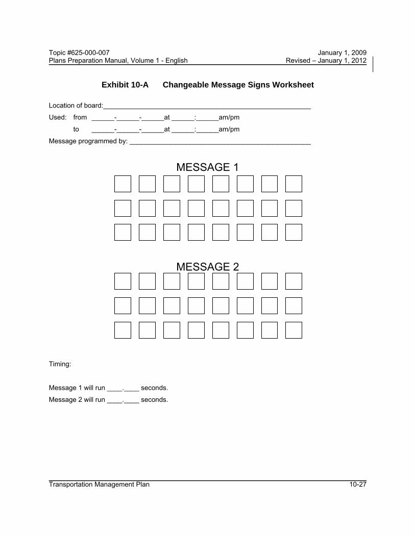
Message Selection Programmed messages should provide appropriate messages for the conditions likely to be encountered. A worksheet is provided and may be placed in the TTC plan. The following items must be carefully considered in the development of a message: 1. Message elements - not necessarily in order
a. Problem statement (where?) b. Effect statement (what?) c. Attention statement (who?) d. Action statement (do?)
2. Message format a. Will vary depending on content b. "Where" or "what" will generally lead c. "Who" and "do" follow in that order d. "Who" often understood from "where"
3. Display format a. Discrete, with entire message displayed at once is most desirable b. Sequential is OK, 2 parts maximum c. Run-on moving displays prohibited d. One abbreviation per panel display desirable, two abbreviations are the
maximum. Route designation is considered as one abbreviation and one word. Guidelines for abbreviations are provided on the following pages.
Topic #625-000-007 January 1, 2009 Plans Preparation Manual, Volume 1 - English Revised – January 1, 2012
Transportation Management Plan 10-27
Exhibit 10-A Changeable Message Signs Worksheet
Location of board:_______________________________________________________
Used: from ______-______-______at ______:______am/pm
to ______-______-______at ______:______am/pm
Message programmed by: ________________________________________________
MESSAGE 1
MESSAGE 2
Timing:
Message 1 will run ____.____ seconds.
Message 2 will run ____.____ seconds.

Topic #625-000-007 January 1, 2009 Plans Preparation Manual, Volume 1 - English Revised – January 1, 2012
Transportation Management Plan 10-28
STANDARD ABBREVIATIONS FOR USE ON CHANGEABLE MESSAGE SIGNS
Standard abbreviations easily understood are:
WORD ABBREV. WORD ABBREV. Boulevard BLVD Normal NORM Center CNTR Parking PKING Emergency EMER Road RD Entrance, Enter ENT Service SERV Expressway EXPWY Shoulder SHLDR Freeway FRWY, FWY Slippery SLIP Highway HWY Speed SPD Information INFO Traffic TRAF Left LFT Travelers TRVLRS Maintenance MAINT Warning WARN
Other abbreviations are easily understood whenever they appear in conjunction with a particular word commonly associated with it. These words and abbreviations are as follows: WORD ABBREV. PROMPT
Access ACCS Road Ahead AHD Fog* Blocked BLKD Lane* Bridge BRDG [Name]* Chemical CHEM Spill Construction CONST Ahead Exit EX, EXT Next* Express EXP Lane Hazardous HAZ Driving Interstate I [Number] Major MAJ Accident Mile MI [Number]* Minor MNR Accident Minute(s) MIN [Number]* Oversized OVRSZ Load Prepare PREP To Stop Pavement PVMT Wet* Quality QLTY Air* Route RT Best* Turnpike TRNPK [Name]* Vehicle VEH Stalled* Cardinal Directions N, E, S, W [Number] Upper, Lower UPR, LWR Level * = Prompt word given first

Topic #625-000-007 January 1, 2009 Plans Preparation Manual, Volume 1 - English Revised – January 1, 2012
Transportation Management Plan 10-29
The following abbreviations are understood with a prompt word by about 75% of the drivers. These abbreviations may require some public education prior to usage.
WORD ABBREV. PROMPT
Condition COND Traffic* Congested CONG Traffic Downtown DWNTN Traffic Frontage FRNTG Road Local LOC Traffic Northbound N-BND Traffic Roadwork RDWK Ahead [Distance] Temporary TEMP Route Township TWNNSHP Limits * = Prompt word given first
Certain abbreviations are prone to inviting confusion because another word is abbreviated or could be abbreviated in the same way. DO NOT USE THESE ABBREVIATIONS: ABBREV. INTENDED WORD WORD ERRONEOUSLY GIVEN
WRNG Warning Wrong ACC Accident Access (Road) DLY Delay Daily LT Light (Traffic) Left STAD Stadium Standard L Left Lane (Merge) PARK Parking Park RED Reduce Red POLL Pollution (Index) Poll FDR Feeder Federal LOC Local Location TEMP Temporary Temperature CLRS Clears Color

Topic #625-000-007 January 1, 2009 Plans Preparation Manual, Volume 1 - English Revised – January 1, 2012
Transportation Management Plan 10-30
10.8.4 Traffic Signals
Frequently portable or temporary traffic signals will be a preferred alternative to a flagger. Also, existing signal operations may need to be revised to accommodate the construction operations. The TTC plan should identify all existing actuated or traffic responsive mode signal operations for main and side street movements that are to be maintained for the duration of the Contract. In addition, the TTC plan should identify the specific alterations (physical location and timing) necessary for existing signals and the location and timing of portable signals. It shall include signal installation plans for each phase of construction. The signal installation plan shall include both the initial signal operation plan and the initial timing adjustments. Traffic control signal requirements or responsibilities shall be included in the Technical Special Provisions. Signal displays and location must meet MUTCD requirements. If temporary signals are used where a pedestrian crossing is present, either existing or temporary, the pedestrian must be accommodated in the signal timing.
Temporary Signal Plans or modification to existing signals should be reviewed by the appropriate section in the district for structural soundness and signal function.

Topic #625-000-007 January 1, 2009 Plans Preparation Manual, Volume 1 - English Revised – January 1, 2012
Transportation Management Plan 10-31
10.9 Channelizing Devices
10.9.1 Type III Barricades
Two Type III barricades should be used to block off or close a roadway. Whenever two barricades are used together, only one warning light is required on each barricade.
10.9.2 Separation Devices
Placing two-lane two-way operations (traffic) (TLTWO) on one roadway of a normally divided highway should be a last resort (see MUTCD) and should be done with special care.
When traffic control must be maintained on one roadway of a normally divided highway, opposing traffic shall be separated either with portable barrier wall or Temporary Traffic Separators (see the Design Standards, Index 600). The use of striping, raised pavement markers, and complementary signing, either alone or in combination is not considered acceptable for separation purposes.
10.9.3 Channelizing Device Alternates
It is intended that cones, Type I and II barricades, vertical panels, drums and tubular markers be considered as alternative channelizing devices to be used at the contractor's option. The only exceptions to this are that tubular markers are not allowed at night and the use of cones shall comply with the notes shown on Design Standards, Index 600. The designer should not further restrict the options of channelizing devices.

Topic #625-000-007 January 1, 2009 Plans Preparation Manual, Volume 1 - English Revised – January 1, 2012
Transportation Management Plan 10-32
10.10 Pavement Markings
10.10.1 Removing Pavement Markings
Existing pavement markings that conflict with temporary work zone traffic patterns must be obliterated where operations will exceed one work period. Painting over existing pavement markings is not permitted.
10.10.2 Raised Retro-Reflective Pavement Markers (RPM)
Raised Retro-Reflective Pavement Markers (RPM) are required as a supplement to all lane lines during construction. For further direction on the use of RPMs in the work zone the designer should refer to the Design Standards, Index 600.
10.10.3 Work Zone Markings
Markings for work zones include "Removable" and "Non-Removable" markings. Section 102-10 of the Standard Specifications describes when each type is required. A separate pay item number is used for each. The designer should be aware of this information and provide appropriate pay items in the plans.
The designer should also consider using an asphalt layer and/or milling with an asphalt layer for covering/removing unneeded markings, especially in areas such as diversions or crossovers. Some construction phase durations may be long enough to require use of interim friction courses. When these type issues arise, the designer should work with the District Pavement Design Engineer, to determine what combination of pavement options best complements the Maintenance of Traffic with the final pavement design.

Topic #625-000-007 January 1, 2009 Plans Preparation Manual, Volume 1 - English Revised – January 1, 2012
Transportation Management Plan 10-33
10.11 Safety Appurtenances for Work Zones
10.11.1 Traffic Barriers
Work zone traffic barriers are considered positive protection devices and are designed either as permanent barriers or as temporary barriers that can be easily relocated. They have four specific functions: to protect traffic from entering work areas, such as excavations or material storage sites; to provide positive protection for workers; to separate two-way traffic; and to protect construction such as false work for bridges and other exposed objects. The designer should anticipate when and where barriers will be needed and include this information and the quantities on the plans. At a minimum, positive protection devices shall be considered in work zone situations that place workers at increased risk from motorized traffic, and where positive protection devices offer the highest potential for increased safety for workers and road users, such as: 1. Work zones that provide workers no means of escape from motorized traffic
(e.g., tunnels, bridges, etc.); 2. Long duration work zones (e.g., two weeks or more at the same location)
resulting in substantial worker exposure to motorized traffic; 3. Projects with anticipated work zone speeds of 45 mph or greater, especially
when combined with high traffic volumes; 4. Work operations that place workers close to travel lanes open to traffic; and 5. Roadside hazards, such as dropoffs or unfinished bridge decks, that will remain
in place overnight or longer.
10.11.2 Barrier Walls (Temporary)
Portable concrete safety shape barriers, also known as portable concrete barriers (PCBs), are used in work zones to protect motorists as well as workers. Care must be taken in their design, installation and maintenance. Installation instructions and flare rates are given in the Design Standards, Index 415 & 600.
When a Temporary Concrete Barrier is used, it shall be placed on a paved surface (temporary or permanent) and shall have a cross slope of 1:10 or flatter. The paved surface shall include the required deflection space behind the barrier. See Design Standards, Index 414 for specific requirements for the use of Type K Temporary Concrete Barrier. When the designer proposes temporary barrier walls, the cross-slope should be checked. Temporary pavement and earthwork shall be included in the plans

Topic #625-000-007 January 1, 2009 Plans Preparation Manual, Volume 1 - English Revised – January 1, 2012
Transportation Management Plan 10-34
if necessary for the proper placement of the barrier system. For requirements for PCB’s that are used on bridges and retaining wall sections, see the Structures Design Guidelines, Section 6.7. When Design Standards, Index 414, Type K Temporary Concrete Barrier is used on bridges, see Design Standards, Index 415 for details on transitioning between the Type K Temporary Concrete Barrier on the bridge and other concrete barrier systems on the adjoining roadway.
Water filled barriers should be used in accordance with the Vendor drawings on the Qualified Products List (QPL).
The designer should show or note the location of all temporary barrier walls in the plans. The plans should also include a work area access plan for those projects with median work which is shielded with barrier wall.
10.11.3 End Treatments
The desirable treatments for exposed ends of barriers are: 1. Connecting to an existing barrier (smooth, structural connections are required -
Refer to the Design Standards, Indexes 410 & 415) or 2. Attaching a crashworthy terminal (such as a crash cushion) or 3. Flaring away to the edge of the clear zone (For Work Zone Clear zones, see the
Design Standards, Index 600)
10.11.4 Modifications of Existing Barriers
When 2-way traffic is placed on a facility that is normally one-way, the existing permanent or temporary barriers will be modified as necessary to ensure their proper crashworthiness during the temporary situation. This will include eliminating non-crashworthy end treatments, snag points or other protrusions normally angled away or hidden from approaching vehicles.

Topic #625-000-007 January 1, 2009 Plans Preparation Manual, Volume 1 - English Revised – January 1, 2012
Transportation Management Plan 10-35
10.11.5 Redirective Crash Cushions
Redirective crash cushions in work zones may be used in the same manner as at permanent highway installations. Crash cushions are used to protect the motorists from the exposed ends of barriers, fixed objects and other hazards within the clear zone. The designer must determine the need for crash cushions, select the appropriate type, and provide the necessary details and quantities in the plans. Selection of a system should be the result of an analysis of site conditions (i.e., space and need).
Redirective crash cushion systems will shield hazards by redirecting vehicles or absorbing end-on hits and are the principal type systems that should be used for shielding exposed ends of temporary concrete barrier wall on FDOT projects. Index 415 provides details for shielding exposed ends of temporary concrete barrier wall using redirective systems. Temporary redirective crash cushions are paid for using the pay item IMPACT ATTENUATOR - CRASH CUSHION (TEMPORARY) (REDIRECTIVE OPTION). When this pay item is used, the contractor is allowed to use any temporary redirective crash cushion on the Qualified Products List, unless the plans restrict the options to a specific redirective crash cushion system. Restricting the options is normally not necessary and when done, must be justified with the reasons documented.
End protection for hazards other than temporary barrier wall ends, must be custom engineered for each independent installation and detailed in the plans. The Design Standards and the AASHTO Roadside Design Guide can be consulted for more information.
Topic #625-000-007 January 1, 2009 Plans Preparation Manual, Volume 1 - English Revised – January 1, 2012
Transportation Management Plan 10-36
10.12 Temporary Traffic Control Plan Details
The Design Standards, Indexes 601 through 670, are layouts of work zone traffic control for typical conditions. These indexes should be referenced only if project conditions are nearly the same as the typical layout. Otherwise, specific plan sheets or details must be prepared. Some conditions that will require specific plan sheets include: 1. Construction work zones near railroad crossings. 2. Detours and signing to reroute vehicles exceeding legal weights where
temporary ACROW panel bridges are present. Coordinate with State Bridge Evaluation Engineer (Office of Maintenance) to determine signing and if necessary the preparation of detour plans for rerouting vehicles exceeding legal weights. See IDS 21600 for more information.
3. Work not covered by a typical layout. 4. Nighttime work requiring special lighting, oversized or additional devices. 5. Ramps and intersections that interrupt the standard layout. 6. Sight distance restrictions such as horizontal or vertical curves. 7. Lane or shoulder configurations that do not match the standards. 8. Special considerations during installation, intermediate traffic shifts and removal. 9. Complex projects, including add-lane projects, which involve many phases, traffic
shifts, entrances and exits. 10. Special plan and notes detailing bus pullover bay/bus stop configuration.
When designing layouts, the following shall be considered:
10.12.1 Taper Lengths
Minimum taper lengths in the Design Standards are shown on individual Index sheets when applicable. When an Index sheet is not used, the minimum taper length shall be calculated by the formulas shown below Table 10.2.
Table 10.2 (taken from MUTCD) gives the criteria for the lengths of the various taper types.

Topic #625-000-007 January 1, 2009 Plans Preparation Manual, Volume 1 - English Revised – January 1, 2012
Transportation Management Plan 10-37
Table 10.2 Taper Length Criteria for Work Zones
Type of Taper Taper Length
UPSTREAM TAPERS
Merging Taper L Minimum Shifting Taper 1/2 L Minimum Shoulder Taper 1/3 L Minimum Two-way Traffic Taper 100 ft. Maximum
DOWNSTREAM TAPERS 100 ft. per lane (use is optional)
Formulas for L are as follows: For speed limits of 40 mph or less:
L = WS2/60 For speed limits of 45 mph or greater:
L = WS "L" is the length of the taper in feet "W" is the width of lateral transition in feet "S" is the posted regulatory speed for the work zone.
10.12.2 Intersecting Road Signing and Signals
Signing for the control of traffic entering and leaving work zones by way of intersecting highways, roads and streets shall be adequate to make drivers aware of work zone conditions. Under no condition will intersecting leg signing be less than a "Road Work Ahead" sign. The designer should remember to include these signs in the estimated quantity for Construction warning signs.
Existing traffic signal operations that require modification in order to carry out work zone traffic control shall be as approved by the District Traffic Operations Engineer (DTOE). If lane shifts occur, signal heads may have to be adjusted to maintain proper position. The DTOE should also determine the need for temporary traffic detection for traffic actuated signals. The TTC plan should include all necessary signal adjustments.

Topic #625-000-007 January 1, 2009 Plans Preparation Manual, Volume 1 - English Revised – January 1, 2012
Transportation Management Plan 10-38
10.12.3 Sight Distance to Delineation Devices
Merging (lane closure) tapers should be obvious to drivers. If restricted sight distance is a problem (e.g., a sharp vertical or horizontal curve approaching the closed lane), the taper should begin well in advance of the view obstruction. The beginning of tapers should not be hidden behind curves.
10.12.4 Pedestrians and Bicyclists
Transportation plans and projects must consider safety and contiguous routes for pedestrians and bicyclists. In developing Temporary Traffic Control (TTC) Plans, when an existing pedestrian way or bicycle way is located within a traffic control work zone, accommodation must be maintained and provision for the disabled must be provided.
When existing pedestrian facilities are disrupted, closed or relocated in a TTC zone, the temporary facility or route shall be detectable and include accessibility features consistent with the features present in the existing facility. See Chapter 6D of the MUTCD for additional guidance.
10.12.4.1 Pedestrian Considerations
There are three threshold considerations in planning for pedestrian safety in work zones on highways and streets: 1. Pedestrians should not be led into direct conflicts with work site vehicles,
equipment or operations. 2. Pedestrians should not be led into direct conflicts with mainline traffic moving
through or around the work site. 3. Pedestrians should be provided with a safe, convenient travel path that replicates
as nearly as possible the most desirable characteristics of sidewalks or footpaths.
Pedestrian accommodations through work zones must include provisions for the disabled. Temporary traffic control devices for vehicular traffic should not be allowed within the pedestrians’ travel path.
At transit stops, provisions should be made to ensure passengers have the ability to board and depart from transit vehicles safely.

Topic #625-000-007 January 1, 2009 Plans Preparation Manual, Volume 1 - English Revised – January 1, 2012
Transportation Management Plan 10-39
Signing should be used to direct pedestrians to safe street crossings in advance of an encounter with a work zone. Signs should be placed at intersections so pedestrians, particularly in high-traffic-volume urban and urbanized areas, are not confronted with midblock crossings.
10.12.4.2 Bicycle Considerations There are several considerations in planning for bicyclists in work zones on highways and streets: 1. Bicyclists should not be led into direct conflicts with mainline traffic, work site
vehicles, or equipment moving through or around traffic control zones. 2. Bicyclists should be provided with a travel route that replicates the most desirable
characteristics of a wide paved shoulder or bicycle lane through or around the work zone.
3. If the work zone interrupts the continuity of an existing shared use path or bike route system, signs directing bicyclists through or around the work zone and back to the path or route should be provided.
4. The bicyclist should not be directed onto the same path used by pedestrians.
10.12.5 Superelevation Horizontal curves constructed in conjunction with temporary work zone diversions, transitions, and crossovers should have the required superelevation. Under conditions where superelevation is not used, the minimum radii that can be applied are listed in the Table 10.3. Superelevation must be included with the design whenever the minimum radii cannot be achieved.
Table 10.3 Minimum Radii for Normal 0.02 Cross Slopes
SPEED (mph)
MINIMUM RADIUS (feet)
65 3130 60 2400 55 1840 50 1390 45 1080 40 820 35 610 30 430

Topic #625-000-007 January 1, 2009 Plans Preparation Manual, Volume 1 - English Revised – January 1, 2012
Transportation Management Plan 10-40
10.12.6 Lane Widths
Existing lane widths of through roadways should be maintained through work zone travel ways wherever practical. The minimum widths for work zone travel lanes shall be 10 ft. for all roadways other than Interstate. On Interstate highways the minimum width for work zone travel lanes shall be 11 ft. except at least one 12 ft. lane in each direction shall be provided.
10.12.7 Lane Closure Analysis
The lane closure analysis is a process used by designers to calculate the peak hour traffic volume and the restricted capacity for open road and signalized intersections. The analysis will determine if a lane closure should or should not be allowed and the time of day or night a lane closure could occur without excessive travel delay.
For all projects under reconstruction, the existing number of lanes shall remain open to traffic when construction is not active.
For widening or major reconstruction on Limited Access facilities, the Temporary Traffic Control Plan will keep the existing number of traffic lanes open at all times throughout the duration of the construction project.
Closing a traffic lane on Interstate or Limited Access facilities can have a significant operational impact in terms of reduced capacity and delay. There will be no daytime lane closures allowed on Florida's Turnpike unless it is approved in writing by the Deputy Executive Director and Chief Operating Officer. Other districts have adopted similar policy for Interstate daytime lane closures; therefore, it is recommended the Designer verify the District’s lane closure policy at the beginning of the design process.
No lane closures in excess of one work day shall be permitted on Limited Access construction where only two traveled lanes in one direction exist. If it becomes necessary to have a long-term lane closure on a four lane Interstate, sufficient documentation shall be provided to the District Secretary for her/his approval.
Chapter 22 of the Highway Capacity Manual 2000, titled “Freeway Facilities Methodology” contains a capacity reduction procedure appropriate for lane closures on Limited Access facilities and other freeways. The Designer may use the HCS2000 method in lieu of the procedure described in this chapter of the PPM. The HCS2000

Topic #625-000-007 January 1, 2009 Plans Preparation Manual, Volume 1 - English Revised – January 1, 2012
Transportation Management Plan 10-41
method considers the intensity of the work activity, the effects of heavy vehicles and presence of ramps. For certain freeway segments it will result in a lower capacity than the lane closure analysis described in the PPM.
Exhibit 10-B includes the lane closure analysis worksheets and two sample analyses. The sample Lane Closure Worksheet (Exhibit 10-B, Sheet 3 of 11) has been cross-referenced to the Lane Closure Symbols and Definitions sheets (Exhibit 10-B, Sheets 1 & 2 of 11) with circled numbers. The circled numbers correspond to the numbers of the symbols and definitions. The symbols and definitions sheets show the designer where to find the necessary information to fill out the lane closure worksheet.
Fill out the top part of the lane closure worksheet and complete the formulas to calculate the hourly percentage of traffic at which a lane closure will be permitted (see Exhibit 10-B, Sheets 6 & 8 of 11). Transfer these percentages to the graph on the Lane Closures 24 Hour Counts sheet (Exhibit 10-B, Sheet 5 of 11). Draw a line across the graph representing the percentage for both open road and signalized intersections (see Exhibit 10-B, Sheets 7 & 9 of 11). Plot the hourly percentages (hourly volume divided by total volume) on the graph. Any hourly percentage extending above the restricted capacity percentage lines for open road or signalized intersections indicated lane closure problems. The bottom of the graph gives times for AM and PM. By coordinating the lane closure problem areas to the time of day, a designer knows when to restrict lane closure.
Many of Florida's roadways have directional peak hour traffic volumes, with inbound morning traffic, and outbound afternoon traffic. Doing a composite lane closure analysis would in many cases require night work. However, if a separate lane closure analysis is calculated for inbound and outbound separately, a lane closure may be allowed and the contractor could work in daylight hours, (See Exhibit 10-B, Sheets 10 & 11 of 11).

Topic #625-000-007 January 1, 2009 Plans Preparation Manual, Volume 1 - English Revised – January 1, 2012
Transportation Management Plan 10-42
Exhibit 10-B Lane Closures Sheet 1 of 11
Symbols and Definitions
1. ATC = Actual Traffic Counts. Use current traffic counts. Traffic counts can be obtained from the Office of Planning, or you may need to get traffic counts done. The designer needs hourly traffic volumes with a total traffic volume for a 24-hour period (see Exhibit 10-B, Sheet 7 of 11).
2. P/D = Peak Traffic to Daily Traffic Ratio. Highest hourly volume divided by the total 24-hour volume. Convert the percentage to a decimal on the Lane Closure Worksheet (see Exhibit 10-B, Sheet 7 of 11).
3. D = Directional Distribution of peak hour traffic on multilane roads. This factor does not apply to a two-lane roadway converted to two-way, one-lane. The directional distribution can be obtained from the Office of Planning.
4. PSCF = Peak Season Conversion Factor. Many counties in Florida have a significant variance in seasonal traffic. The designer should use the PSCF for the week in which the actual traffic count was conducted. The Office of Planning has tables showing Peak Season Conversion Factors for every county in Florida. (See sample table of values on Exhibit 10-B, Sheet 4 of 11).
5. RTF = Remaining Traffic Factor is the percentage of traffic that will not be diverted onto other facilities during a lane closure. Convert the percentage to a decimal on the Lane Closure Worksheet. This is an estimate that the designer must make on his own, or with help from the Office of Planning. Range: 0% for all traffic diverted to 100% for none diverted.
6. G/C = Ratio of Green to Cycle Time. This factor is to be applied when lane closure is through or within 600 ft. of a signalized intersection. The Office of Traffic Engineering has timing cycles for all traffic signals.
7. V = Peak Hour Traffic Volume. The designer calculates the peak hour traffic volume by multiplying the actual traffic count, times peak to daily traffic ratio, times directional factor, times peak seasonal factor, times remaining traffic factor. This calculation will give the designer the expected traffic volume of a roadway at the anticipated time of a lane closure.

Topic #625-000-007 January 1, 2009 Plans Preparation Manual, Volume 1 - English Revised – January 1, 2012
Transportation Management Plan 10-43
Exhibit 10-B Lane Closures, Sheet 2 of 11
Symbols and Definitions (Continued)
8. C = Capacity of a 2L, 4L 6L, or 8L roadway with one lane closed, and the remaining lane(s) unrestricted by lateral obstructions. The capacity of a 4L, 6L, or 8L roadway is based on lane closure in only one direction (see Lane Closure Capacity Table on Exhibit 10-B, Sheet 3 of 11).
9. RC = Restricting Capacity of the above facilities by site specific limitations detailed in the Temporary Traffic Control plans which apply to travel lane width, lateral clearance and the work zone factor. The work zone factor only applies to two lane roadways (see the tables on Exhibit 10-B, Sheet 4 of 11 to obtain the Obstruction Factor and Work Zone Factor).
10. OF = Obstruction Factor which reduces the capacity of the remaining travel lane(s) by restricting one or both of the following components: Travel lane width less than 12 ft. and lateral clearance less than 6 ft. (see TTC plan and Obstruction Factor Table in Exhibit 10-B, Sheet 4 of 11).
11. WZF = Work Zone Factor (WZF) is directly proportional to the work zone length (WZL). The capacity is reduced by restricting traffic movement to a single lane while opposing traffic queues. The WZF and WZL only apply to a two lane roadway converted to two way, one lane (see the Work Zone Factor Table on Exhibit 10-B, Sheet 4 of 11).
12. TLW = Travel Lane Width is used to determine the obstruction factor (see TTC plan and the Obstruction Factor Table on Exhibit 10-B, Sheet 4 of 11).
13. LC = Lateral Clearance is the distance from the edge of the travel lane to the obstruction. The lateral clearance is used to determine the obstruction factor (see TTC plans and Obstruction Factor Table on Exhibit 10-B, Sheet 4 of 11).

Topic #625-000-007 January 1, 2009 Plans Preparation Manual, Volume 1 - English Revised – January 1, 2012
Transportation Management Plan 10-44
Exhibit 10-B, Lane Closures, Sheet 3 of 11
LANE CLOSURE WORKSHEET FINANCIAL PROJECT ID:_____________________ FAP NO.:______________________________
COUNTY:__________________________________ DESIGNER:____________________________
NO. EXISTING LANES:_________ SCOPE OF WORK:______________________
____________________________________________________________________________________
Calculate the peak hour traffic volume (V)
V=ATC 1 X P/D 2 X D 3 X PSCF 4 X RTF 5 = 7_
LANE CLOSURE CAPACITY TABLE
Capacity (C) of an Existing 2-Lane – Converted to 2-Way, 1-Lane = 1400 VPH Capacity (C) of an Existing 4-Lane – Converted to 1-Way, 1-Lane = 1800 VPH Capacity (C) of an Existing 6-Lane – Converted to 1-Way, 2-Lane = 3600 VPH Capacity (C) of an Existing 8-Lane – Converted to 1-Way, 3-Lane = 5400 VPH
Factors restricting Capacity:
TLW 12 LC 13 WZL 11 G/C 6___
Calculate the Restricted Capacity (RC) at the Lane Closure Site by multiplying the appropriate 2L, 4L, 6L, or 8L Capacity (C) from the Table above by the Obstruction Factor (OF) and the Work Zone Factor (WZF). If the Lane Closure is through or within 600 ft. of a signalized intersection, multiply the RC by the G/C Ratio.
RC (Open Road) = C 8 X OF 10 X WZF 11 = 9__
RC (Signalized) = RC (Open Road) 9 X G/C 6 = __9__
If V ≤ RC, there is no restriction on Lane Closure If V > RC, calculate the hourly percentage of ADT at which Lane Closure will be permitted
RC (Open Road) 9_ _ Open Road % =___________________________________________________________ = _______%
(ATC 1 X D 3 X PSCF 4 X RTF _5 )
Signalized % = Open Road % ______ X G/C 6 = _____ %
Plot 24 hour traffic to determine when Lane Closure permitted. (See Exhibit 10-B, Sheet 5 of 11)
NOTE: For Existing 2-Lane Roadways, D = 1.00. Work Zone Factor (WZF) applies only to 2-Lane Roadways.
For RTF < 1.00, briefly describe alternate route ______________________________________________
____________________________________________________________________________________
____________________________________________________________________________________

Topic #625-000-007 January 1, 2009 Plans Preparation Manual, Volume 1 - English Revised – January 1, 2012
Transportation Management Plan 10-45
Exhibit 10-B, Lane Closures, Sheet 4 of 11 Lane Closures – Capacity Adjustment Factors
Peak Season Conversion Factor (PSCF) Sample 1998 Peak Season Factor Category Report for Tropic County
WK Dates SF PSCF WK Dates SF PSCF 9 02/22 – 02/28/98 1.14 1.48 15 04/05 – 04/11/98 0.86 1.12
10 03/01 – 03/07/98 1.04 1.35 16 04/12 – 04/18/98 0.87 1.13 11 03/08 – 03/14/98 0.94 1.22 17 04/19 – 04/25/98 0.90 1.17 12 03/15 – 03/21/98 0.83 1.08 18 04/26 – 05/02/98 0.93 1.21 13 03/22 – 03/28/98 0.84 1.09 19 05/03 – 05/09/98 0.96 1.25 14 03/29 – 04/04/98 0.85 1.11 20 05/10 – 05/16/98 0.99 1.29
Obstruction Factors (OF) Lateral
Clearance (LC) (feet)
Travel Lane Width (TLW) (feet)
12 11 10 9 6 4 2
0.0
1.00 0.98 0.94 0.86
0.96 0.94 0.90 0.82
0.90 0.87 0.83 0.75
0.80 0.77 0.72 0.65
Work Zone Factors (WZF) WZL (ft.) WZF WZL (ft.) WZF WZL (ft.) WZF
200 400 600 800
1000 1200 1400 1600 1800 2000
0.99 0.97 0.96 0.95 0.93 0.92 0.91 0.90 0.89 0.88
2200 2400 2600 2800 3000 3200 3400 3600 3800 4000
0.87 0.86 0.85 0.84 0.83 0.82 0.81 0.80 0.80 0.79
4200 4400 4600 4800 5000 5200 5400 5600 5800 6000
0.78 0.77 0.77 0.76 0.75 0.75 0.74 0.73 0.73 0.72
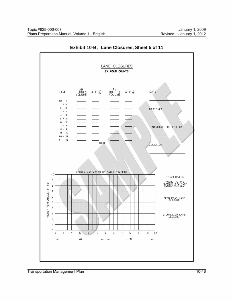
Topic #625-000-007 January 1, 2009 Plans Preparation Manual, Volume 1 - English Revised – January 1, 2012
Transportation Management Plan 10-46
Exhibit 10-B, Lane Closures, Sheet 5 of 11

Topic #625-000-007 January 1, 2009 Plans Preparation Manual, Volume 1 - English Revised – January 1, 2012
Transportation Management Plan 10-47
Exhibit 10-B, Lane Closures, Sheet 6 of 11 LANE CLOSURE WORKSHEET
FINANCIAL PROJECT ID: 123456-7-89-10 FAP NO.: NA
COUNTY: Tropic DESIGNER: Yates NO. EXISTING LANES: 2 SCOPE OF WORK: Widen and Resurface
Calculate the peak hour traffic volume (V)
V=ATC 15000 X P/D 0.083 X D NA X PSCF 1.17 X RTF 0.75 = 1092_
LANE CLOSURE CAPACITY TABLE
Capacity (C) of an Existing 2-Lane – Converted to 2-Way, 1-Lane = 1400 VPH Capacity (C) of an Existing 4-Lane – Converted to 1-Way, 1-Lane = 1800 VPH Capacity (C) of an Existing 6-Lane – Converted to 1-Way, 2-Lane = 3600 VPH Capacity (C) of an Existing 8-Lane – Converted to 1-Way, 3-Lane = 5400 VPH
Factors restricting Capacity:
TLW 10 LC 4 WZL 3200 G/C 0.64_
Calculate the Restricted Capacity (RC) at the Lane Closure Site by multiplying the appropriate 2L, 4L, 6L, or 8L Capacity (C) from the table above by the Obstruction Factor (OF) and the Work Zone Factor (WZF). If the Lane Closure is through or within 600 ft. of a signalized intersection, multiply the RC by the G/C Ratio.
RC (Open Road) = C 1400 X OF 0.87 X WZF 0.82 = 999 _ RC (Signalized) = RC (Open Road) 999 X G/C 0.64 = 639 _
If V ≤ RC, there is no restriction on Lane Closure If V > RC, calculate the hourly percentage of ADT at which Lane Closure will be permitted
RC (Open Road) 999__
Open Road % =__________________________________________________________= 7.59 % (ATC 15000 X D 1.00 X PSCF 1.17 X RTF 0.75 )
Signalized % = Open Road % 7.59 X G/C 0.64 = 4.86 %
Plot 24 hour traffic to determine when Lane Closure permitted. (See Exhibit 10-B, Sheet 7 of 11)
NOTE: For Existing 2-Lane Roadways, D = 1.00. Work Zone Factor (WZF) applies only to 2-Lane Roadways.
For RTF < 1.00, briefly describe alternate route: 25% of existing traffic diverted on Bullard Blvd., north on Newhall Lane, then east on Xanders Expressway.

Topic #625-000-007 January 1, 2009 Plans Preparation Manual, Volume 1 - English Revised – January 1, 2012
Transportation Management Plan 10-48
Exhibit 10-B, Lane Closures, Sheet 7 of 11
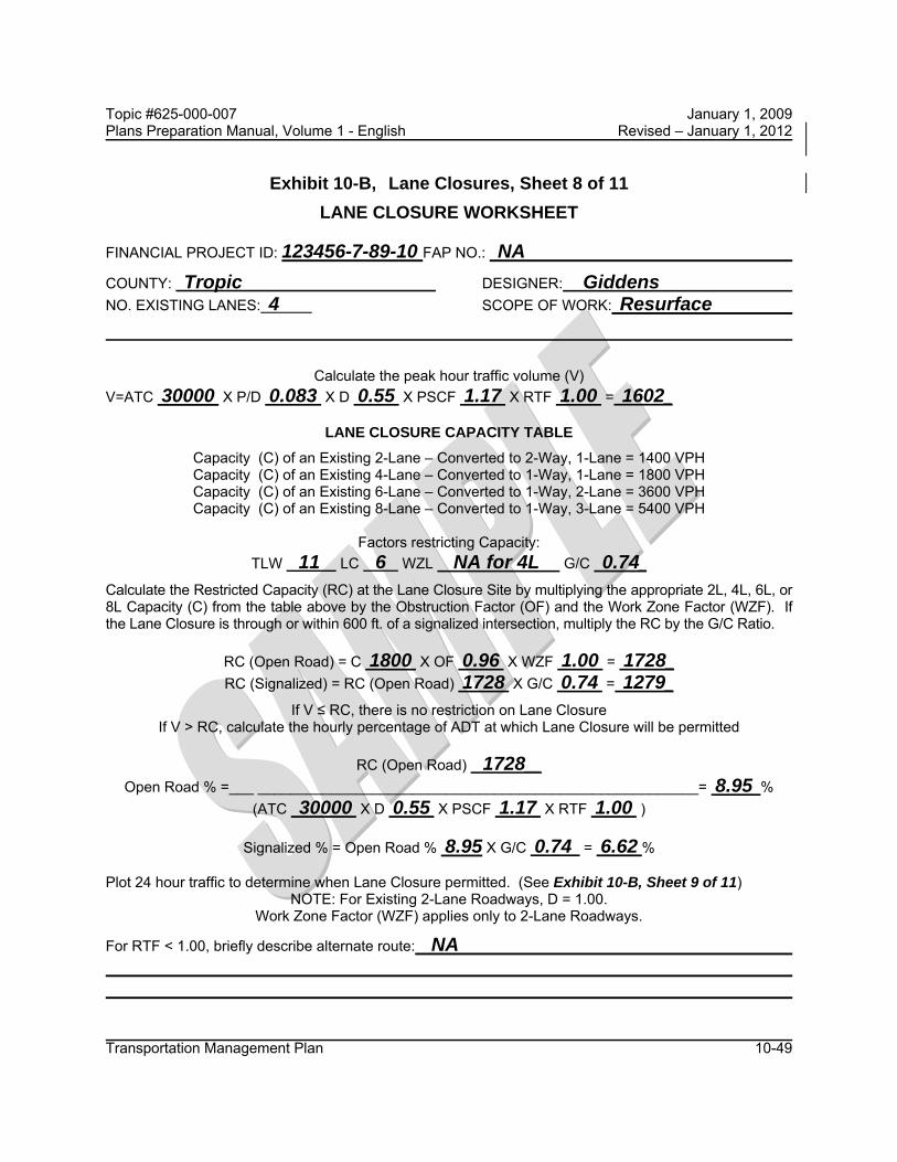
Topic #625-000-007 January 1, 2009 Plans Preparation Manual, Volume 1 - English Revised – January 1, 2012
Transportation Management Plan 10-49
Exhibit 10-B, Lane Closures, Sheet 8 of 11 LANE CLOSURE WORKSHEET
FINANCIAL PROJECT ID: 123456-7-89-10 FAP NO.: NA
COUNTY: Tropic DESIGNER: Giddens NO. EXISTING LANES: 4 SCOPE OF WORK: Resurface
Calculate the peak hour traffic volume (V)
V=ATC 30000 X P/D 0.083 X D 0.55 X PSCF 1.17 X RTF 1.00 = 1602_
LANE CLOSURE CAPACITY TABLE
Capacity (C) of an Existing 2-Lane – Converted to 2-Way, 1-Lane = 1400 VPH Capacity (C) of an Existing 4-Lane – Converted to 1-Way, 1-Lane = 1800 VPH Capacity (C) of an Existing 6-Lane – Converted to 1-Way, 2-Lane = 3600 VPH Capacity (C) of an Existing 8-Lane – Converted to 1-Way, 3-Lane = 5400 VPH
Factors restricting Capacity:
TLW 11 LC 6 WZL NA for 4L G/C 0.74_
Calculate the Restricted Capacity (RC) at the Lane Closure Site by multiplying the appropriate 2L, 4L, 6L, or 8L Capacity (C) from the table above by the Obstruction Factor (OF) and the Work Zone Factor (WZF). If the Lane Closure is through or within 600 ft. of a signalized intersection, multiply the RC by the G/C Ratio.
RC (Open Road) = C 1800 X OF 0.96 X WZF 1.00 = 1728_ RC (Signalized) = RC (Open Road) 1728 X G/C 0.74 = 1279_
If V ≤ RC, there is no restriction on Lane Closure If V > RC, calculate the hourly percentage of ADT at which Lane Closure will be permitted
RC (Open Road) 1728__
Open Road % =___ ______________________________________________________= 8.95 % (ATC 30000 X D 0.55 X PSCF 1.17 X RTF 1.00 )
Signalized % = Open Road % 8.95 X G/C 0.74 = 6.62 %
Plot 24 hour traffic to determine when Lane Closure permitted. (See Exhibit 10-B, Sheet 9 of 11)
NOTE: For Existing 2-Lane Roadways, D = 1.00. Work Zone Factor (WZF) applies only to 2-Lane Roadways.
For RTF < 1.00, briefly describe alternate route: NA

Topic #625-000-007 January 1, 2009 Plans Preparation Manual, Volume 1 - English Revised – January 1, 2012
Transportation Management Plan 10-50
Exhibit 10-B, Lane Closures, Sheet 9 of 11

Topic #625-000-007 January 1, 2009 Plans Preparation Manual, Volume 1 - English Revised – January 1, 2012
Transportation Management Plan 10-51
Exhibit 10-B, Lane Closures, Sheet 10 of 11

Topic #625-000-007 January 1, 2009 Plans Preparation Manual, Volume 1 - English Revised – January 1, 2012
Transportation Management Plan 10-52
Exhibit 10-B, Lane Closures, Sheet 11 of 11
LANE CLOSURE WORKSHEET SUMMARY LANE SAMPLE WITH SIGNIFICANT AM-PM PEAKS
SAMPLES = INBOUND (WB), COMPOSITE (EB & WB), OUTBOUND (EB) SITE = SR 60 @ US 301 EAST OF TAMPA, HILLSBOROUGH CO.
COMPONENT INBOUND COMPOSITE OUTBOUND
ADT P/D D PSCF RTF V TLW LC C OF RC (OPEN ROAD) G/C RC (SIGNAL) % OPEN ROAD % SIGNAL LANE CLOSURE (OPEN ROAD) LANE CLOSURE (SIGNAL)
21,760 0.103 1.00 1.17 1.00 2622 12 0
1800 0.86 1548 0.50 774 6.10 3.05
7:00 AM 4.00 PM
6:00 AM. 9:00 PM.
42,232 0.073 0.60 1.17 1.00 2164 12 0
1800 0.86 1548 0.50 774 5.20 2.60
7:00 AM 7:30 PM
6:00 AM 10:30 PM
20,472 0.092 1.00 1.17 1.00 2203 12 0
1800 0.86 1548 0.50 774 6.50 3.25
11:30 AM 7:30 PM
7:30 AM 10:30 PM

Topic #625-000-007 January 1, 2009 Plans Preparation Manual, Volume 1 - English Revised – January 1, 2012
Transportation Management Plan 10-53
10.12.8 Traffic Pacing Design
A traffic pacing design is prepared to provide adequate work time for overhead construction on limited access highways. Traffic pacing is a traffic control technique that facilitates short duration overhead work operations by pacing traffic at a slow speed for a predetermined distance upstream of the work area. The Department frequently uses this technique for installing overhead sign structures, replacing sign panels, installing cantilever trusses and, when site conditions allow, placing bridge beams. Traffic pacing may also be used by utility companies for the installation of utility crossings. Based on the required work time and other inputs such as traffic volumes, regulatory speed and pacing speed, the designer will prepare a traffic control plan that defines the allowable pacing hours, pacing distance, location of warning signs, interchange ramp closures and other critical information.
The Traffic Control Plan will document the layout and required resources for the pacing operation. The designer will assess the geometric conditions to ensure that sight distance and other geometric conditions are addressed. Index 655 of the Design Standards provides a basis for the traffic pacing operation and the development of the Traffic Control Plan. Index 655 includes details of the four stages of a pacing operation and additional information related to: 1. Signing
2. Use of changeable message signs and attenuators
3. Use of traffic control officers
4. Contractor requirements
If it is determined that a pacing operation will be used, the designer should obtain concurrence from the Captain of the Florida Highway Patrol troop who will assist in the operation.
Exhibit 10-C contains definitions, and the procedure for calculating the pacing distance and the time intervals during which a pacing operation will be allowed.

Topic #625-000-007 January 1, 2009 Plans Preparation Manual, Volume 1 - English Revised – January 1, 2012
Transportation Management Plan 10-54
Exhibit 10-C Traffic Pacing Sheet 1 of 12
Definitions
1. HTD = Hourly Traffic Demand in vehicles / hour. Hourly traffic volumes will be required for each hour in the analysis period. Hourly traffic volumes may be obtained from the Project Traffic Report, the Office of Planning or from field data collection. The designer should use the most recent values available.
2. tw = Work Duration in minutes. This is the work time allotted for overhead construction. This value is usually between 10 and 30 minutes, and input in 5 minute increments.
3. Sp = Pacing Speed in MPH. This is the speed that the pacing vehicles travel and is usually 10, 15 or 20 MPH.
4. Sr = Regulatory Speed in MPH. This is the posted speed on the roadway segment.
5. L = Total Pacing Distance in miles. This is the total distance that the pacing vehicles are traveling at the pacing speed. It includes the distance required to clear traffic past the work area, and the distance required to provide the work duration. This distance is measured upstream from the work area.
6. FHV = Heavy-vehicle adjustment factor. This factor is used to convert hourly traffic to equivalent passenger cars. Heavy vehicles include trucks, busses and recreational vehicles.
7. Pt = Percent Trucks (%).
8. FLOWA = Traffic Demand Flow Rate in passenger cars per hour per lane. This is the traffic flow rate approaching the pacing operation from the upstream direction.
9. FLOWB = Forced Traffic Flow Rate in passenger cars per hour per lane. This is the traffic flow rate within the queue.
10. FLOWC = Congested Traffic Flow Rate in passenger cars per hour per lane. This is the traffic flow rate of the vehicles escaping the queue.
11. QGR = Queue Growth Rate in MPH. The rate that the queue grows from the time the pacing operation begins until the pace cars exit the roadway.

Topic #625-000-007 January 1, 2009 Plans Preparation Manual, Volume 1 - English Revised – January 1, 2012
Transportation Management Plan 10-55
Exhibit 10-C Traffic Pacing, Sheet 2 of 12
Definitions (Continued)
12. QDR = Queue Dissipation Rate in MPH. The rate that the queue dissipates after the pace cars exit the roadway.
13. SWA = Speed of Shockwave ‘A’ in MPH. The speed of the shockwave at the boundary between traffic ‘FLOWA’ and traffic ‘FLOWB’.
14. SWB = Speed of Shockwave ‘B’ in MPH. The speed of the shockwave at the boundary between traffic ‘FLOWB’ and traffic ‘FLOWC’.
15. DENSITYA = Free Flow Density in vehicles / mile. The traffic density under free flow conditions.
16. DENSITYB = Forced Flow Density in vehicles per mile. The traffic density under forced flow conditions.
17. DENSITYC = Congested Flow Density in vehicles per mile. The traffic density under congested flow conditions.
18. N = Number of Lanes
19. Ttotal = Total time to conduct the pacing operation. The time from when the pace cars enter the roadway until the queue has dissipated and normal traffic flow is restored.
20. ATC = Actual Traffic Counts. Traffic counts can be obtained from the Office of Planning or collected on the project site. The designer needs hourly traffic volumes for a 24 hour period.
21. PSCF = Peak Season Conversion Factor. The Office of Planning publishes tables with the PSCF for each county in Florida. Each county table has a PSCF for the week that the traffic counts were collected. The factor converts the ATC to Peak Season Traffic representing the highest daily traffic for the year.
22. AADT = Average Annual Daily Traffic. In lieu of actual traffic counts the designer may use AADT provided by the Office of Planning. The AADT must be adjusted to peak season hourly traffic by applying the model correction factor and the hourly distribution factors.

Topic #625-000-007 January 1, 2009 Plans Preparation Manual, Volume 1 - English Revised – January 1, 2012
Transportation Management Plan 10-56
Exhibit 10-C Traffic Pacing, Sheet 3 of 12
Definitions (Continued)
23. MOCF = Model Correction Factor. The MOCF converts AADT to peak season traffic.
24. HDF = Hourly Distribution Factors. Multiply the AADT by the HDT to obtain the traffic volume for a particular hour. The Office of Planning publishes hourly distribution factors for regions of the state.
25. C = Capacity. The capacity of the roadway under free flow conditions in passenger cars per hour per lane.
26. Pc/h/ln = passenger cars per hour per lane. Pc/h/ln represents the traffic volume or capacity of one lane adjusted for heavy vehicles.
27. TD = Time to dissipate the queue in minutes. TD is the amount of time beginning at the point when the pacing vehicles leave the roadway until the traffic returns to normal operating conditions.
28. Qmax = the maximum queue length. The maximum queue length occurs when the pacing vehicles reach the work zone.
29. SpeedC = the average speed of passenger cars when the roadway reaches capacity.

Topic #625-000-007 January 1, 2009 Plans Preparation Manual, Volume 1 - English Revised – January 1, 2012
Transportation Management Plan 10-57
Exhibit 10-C Traffic Pacing, Sheet 4 of 12 Worksheets
FINANCIAL PROJECT ID: FAP NO: COUNTY: DESIGNER: STATE ROAD / LOCAL ROAD NAME: SCOPE OF WORK: SECTION NO: MILE POST LIMITS: DIRECTION OF TRAVEL (NB, SB, EB or WB):
Project Inputs: 1. Regulatory Speed (Sr) = 2. Pacing Speed (Sp) = 3. Work Duration (tw) = 4. Number of Lanes (N): 5. Percent Trucks (Pt): 6. Peak Season Conversion Factor (PSCF) or Model Correction Factor (MOCF) = 7. 24-hour Traffic Volumes:
Hour AM Traffic Volume Hour PM Traffic Volume
24 - 1
12-13
1 - 2
13-14
2 - 3
14-15
3 - 4
15-16
4 - 5
16-17
5 - 6
17-18
6 - 7
18-19
7 - 8
19-20
8 - 9
20-21
9 -10
21-22
10-11
22-23
11-12
23-24

Topic #625-000-007 January 1, 2009 Plans Preparation Manual, Volume 1 - English Revised – January 1, 2012
Transportation Management Plan 10-58
Exhibit 10-C Traffic Pacing, Sheet 5 of 12 Worksheets (Continued)
STEP 1: Calculate the hourly percentage of peak season traffic for each hour of the day (in pcphpl) and plot the 24 hour traffic percentages.
A. Calculate the Heavy Vehicle Adjustment Factor, 𝐹�� = 1 + � ������ 0.5.
B. If using actual traffic counts calculate the hourly traffic demand as follows:
𝐻𝑇𝐷� =(𝐴𝑇𝐶�)(𝑃𝑆𝐶𝐹)(𝐹��)
𝑁
If using average annual daily traffic calculate the hourly traffic demand as follows:
𝐻𝑇𝐷� =(𝐴𝐴𝐷𝑇)(𝑀𝑂𝐶𝐹)(𝐻𝐷𝐹)(𝐹��)
𝑁
C. Calculate the percent capacity, %𝐶 = �����
(100) where:
C = 2,400 pc/h/ln for 70 mph regulatory speed C = 2,300 pc/h/ln for 65 mph regulatory speed C = 2,250 pc/h/ln for 60 mph regulatory speed C = 2,220 pc/h/ln for 55 mph regulatory speed C = 2,150 pc/h/ln for 50 mph regulatory speed
Hour AM Hourly
Traffic Demand Percent Capacity
Hour PM Hourly
Traffic Demand Percent Capacity
24 - 1
12-13
1 - 2
13-14
2 - 3
14-15
3 - 4
15-16
4 - 5
16-17
5 - 6
17-18
6 - 7
18-19
7 - 8
19-20
8 - 9
20-21
9 - 10
21-22
10-11
22-23
11-12
23-24

Topic #625-000-007 January 1, 2009 Plans Preparation Manual, Volume 1 - English Revised – January 1, 2012
Transportation Management Plan 10-59
Exhibit 10-C Traffic Pacing, Sheet 6 of 12 Worksheets (Continued)
STEP 2: Calculate the Pacing Length, L.
𝐿 = 𝑆� ������ � ��
�����+ 1�
STEP 3: Calculate the Maximum Queue Length, 𝑄���.
𝐹𝐿𝑂𝑊� = 𝐻𝑇𝐷�
𝐷𝐸𝑁𝑆𝐼𝑇𝑌� = �������
𝐹𝐿𝑂𝑊� = 1,800 𝑝𝑐𝑝ℎ𝑝𝑙 (based on a 2.0 sec headway)
𝐷𝐸𝑁𝑆𝐼𝑇𝑌� = �������
𝑆𝑊� = ����������������������������
𝑄𝐺𝑅 = 𝑆� − 𝑆𝑊�
𝑄��� = 𝑄𝐺𝑅 � ����
0%
20%
40%
60%
80%
100%
120%
0 2 4 6 8 10 12 14 16 18 20 22 24 HO
UR
LY P
ERC
ENTA
GE
OF
CAP
ACIT
Y
(PEA
K SE
ASO
N T
RAF
FIC
)
Hours
HOURLY VARIATION OF DAILY TRAFFIC 40% Capacity Line

Topic #625-000-007 January 1, 2009 Plans Preparation Manual, Volume 1 - English Revised – January 1, 2012
Transportation Management Plan 10-60
Exhibit 10-C Traffic Pacing, Sheet 7 of 12 Worksheets (Continued)
STEP 4: Calculate the Time to Dissipate the Queue, TD.
𝐹𝐿𝑂𝑊� = 2,400 pcphpl (𝑎𝑠𝑠𝑢𝑚𝑒𝑑 𝑐𝑎𝑝𝑎𝑐𝑖𝑡𝑦 𝑣𝑎𝑙𝑢𝑒)
𝐷𝐸𝑁𝑆𝐼𝑇𝑌� = ������������
� where:
𝑆𝑝𝑒𝑒𝑑� = 53𝑚𝑝ℎ (𝑓𝑜𝑟 70 𝑚𝑝ℎ 𝑟𝑒𝑔𝑢𝑙𝑎𝑡𝑜𝑟𝑦 𝑠𝑝𝑒𝑒𝑑)
𝑆𝑝𝑒𝑒𝑑� = 50𝑚𝑝ℎ (𝑓𝑜𝑟 50 − 65 𝑚𝑝ℎ 𝑟𝑒𝑔𝑢𝑙𝑎𝑡𝑜𝑟𝑦 𝑠𝑝𝑒𝑒𝑑)
𝑆𝑊� = � ����������������������������
�
𝑄𝐷𝑅 = 𝑆𝑊� − 𝑆𝑊�
𝑇� = ��������
�60
STEP 5: Calculate the Total Time to Conduct the Pacing Operation, Ttotal.
𝑇����� = � ����60 + 𝑇�
Label the pacing window chart by designating the time(s) that a pacing operation can begin and the time(s) after which a pacing operation cannot begin. The time that a pacing operation can begin is the point at which the percent capacity falls below 40%. The time after which a pacing operation cannot be started is the point at which the percent capacity reaches 40% minus Ttotal. Use one hour increments only.
0%
20%
40%
60%
80%
100%
120%
0 2 4 6 8 10 12 14 16 18 20 22 24
HO
UR
LY
PER
CEN
TAG
E O
F
CAP
ACIT
Y
(PEA
K S
EASO
N T
RAF
FIC
)
Hours
HOURLY VARIATION OF DAILY TRAFFIC 40% Capacity Line

Topic #625-000-007 January 1, 2009 Plans Preparation Manual, Volume 1 - English Revised – January 1, 2012
Transportation Management Plan 10-61
Exhibit 10-C Traffic Pacing, Sheet 8 of 12 Sample Worksheets
FINANCIAL PROJECT ID: 123456-7-89-10 FAP NO: NA COUNTY: Tropic DESIGNER: John Smith STATE ROAD / LOCAL ROAD NAME: I-4 @ Lee Road SCOPE OF WORK: Replace Overhead Sign SECTION NO: 75280 MILE POST LIMITS: 2.300 DIRECTION OF TRAVEL (NB, SB, EB or WB): East Bound
Project Inputs: 1. Regulatory Speed (Sr) = 65 MPH
2. Pacing Speed (Sp) = 20 MPH
3. Work Duration (tw) = 25 minutes
4. Number of Lanes (N) = 3
5. Percent Trucks (Pt) = 6.71
6. Peak Season Conversion Factor (PSCF) = 1.04
7. 24-hour Traffic Volumes:
Hour AM Traffic Volume Hour PM Traffic Volume
24 - 1 1406 12-13 6118 1 - 2 772 13-14 6390 2 - 3 599 14-15 6771 3 - 4 591 15-16 6675 4 - 5 942 16-17 6607 5 - 6 2116 17-18 5989 6 - 7 5666 18-19 5810 7 - 8 7302 19-20 5078 8 - 9 7173 20-21 4139
9 - 10 6719 21-22 3563 10-11 6275 22-23 3008 11-12 6067 23-24 2276
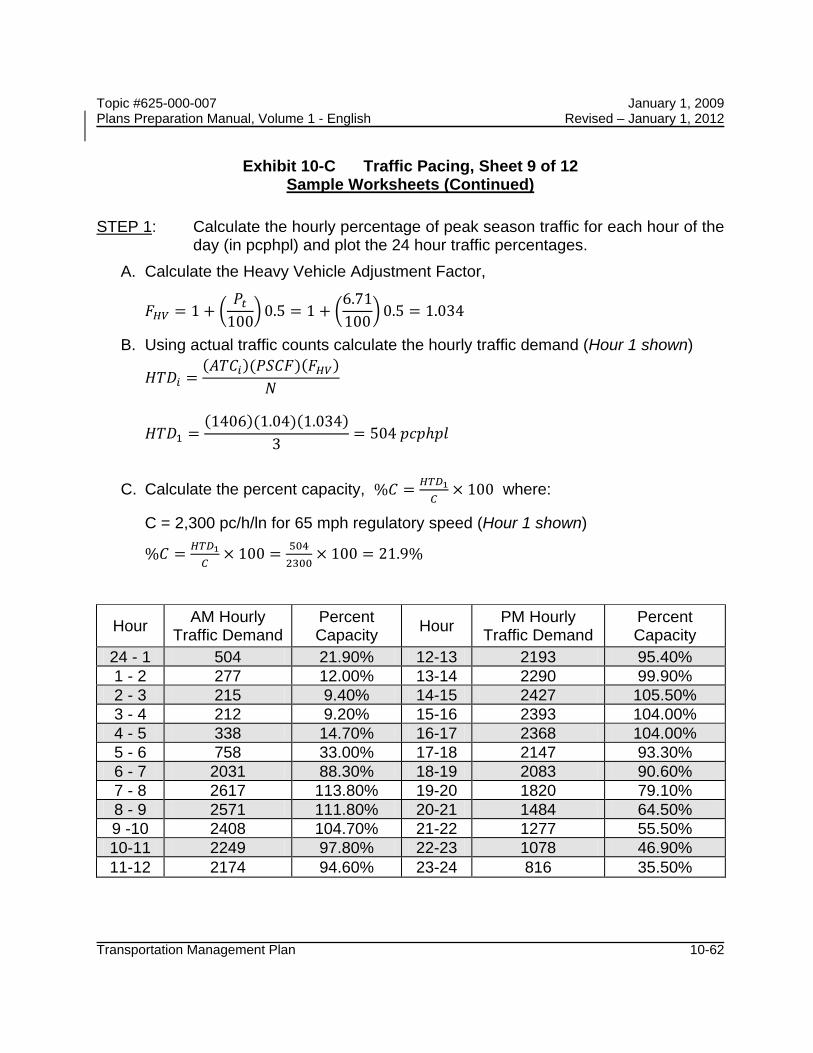
Topic #625-000-007 January 1, 2009 Plans Preparation Manual, Volume 1 - English Revised – January 1, 2012
Transportation Management Plan 10-62
Exhibit 10-C Traffic Pacing, Sheet 9 of 12 Sample Worksheets (Continued)
STEP 1: Calculate the hourly percentage of peak season traffic for each hour of the day (in pcphpl) and plot the 24 hour traffic percentages.
A. Calculate the Heavy Vehicle Adjustment Factor,
𝐹�� = 1 + �𝑃�
100�0.5 = 1 + �
6.71100�
0.5 = 1.034
B. Using actual traffic counts calculate the hourly traffic demand (Hour 1 shown)
𝐻𝑇𝐷� =(𝐴𝑇𝐶�)(𝑃𝑆𝐶𝐹)(𝐹��)
𝑁
𝐻𝑇𝐷� =(1406)(1.04)(1.034)
3= 504 𝑝𝑐𝑝ℎ𝑝𝑙
C. Calculate the percent capacity, %𝐶 = ����
�× 100 where:
C = 2,300 pc/h/ln for 65 mph regulatory speed (Hour 1 shown)
%𝐶 = �����
× 100 = �������
× 100 = 21.9%
Hour AM Hourly Traffic Demand
Percent Capacity Hour PM Hourly
Traffic Demand Percent Capacity
24 - 1 504 21.90% 12-13 2193 95.40% 1 - 2 277 12.00% 13-14 2290 99.90% 2 - 3 215 9.40% 14-15 2427 105.50% 3 - 4 212 9.20% 15-16 2393 104.00% 4 - 5 338 14.70% 16-17 2368 104.00% 5 - 6 758 33.00% 17-18 2147 93.30% 6 - 7 2031 88.30% 18-19 2083 90.60% 7 - 8 2617 113.80% 19-20 1820 79.10% 8 - 9 2571 111.80% 20-21 1484 64.50% 9 -10 2408 104.70% 21-22 1277 55.50% 10-11 2249 97.80% 22-23 1078 46.90% 11-12 2174 94.60% 23-24 816 35.50%

Topic #625-000-007 January 1, 2009 Plans Preparation Manual, Volume 1 - English Revised – January 1, 2012
Transportation Management Plan 10-63
Exhibit 10-C Traffic Pacing, Sheet 10 of 12 Sample Worksheets (Continued)
STEP 2: Calculate the Pacing Length, L. 𝐿 = 𝑆� �
����� � ��
�����+ 1� = 20 ���
��� � ��
�����+ 1� = 12.04 𝑚𝑖𝑙𝑒𝑠
STEP 3: Calculate the Maximum Queue Length, 𝑄���, for hour 5 (4am to 5am).
𝐹𝐿𝑂𝑊� = 𝐻𝑇𝐷� = 338
𝐷𝐸𝑁𝑆𝐼𝑇𝑌� = �������
= �����
= 5.20 ����
/𝑙
𝐹𝐿𝑂𝑊� = 1,800 𝑝𝑐𝑝ℎ𝑝𝑙 (based on a 2.0 sec headway)
𝐷𝐸𝑁𝑆𝐼𝑇𝑌� = �������
= ������
= 90 ����
/𝑙
𝑆𝑊� = ����������������������������
= ������������.��
= 17.24 𝑚𝑝ℎ
𝑄𝐺𝑅 = 𝑆� − 𝑆𝑊� = 20 − 17.24 = 2.76 𝑚𝑝ℎ
𝑄��� = 𝑄𝐺𝑅 � ���� = 2.76 ���.��
��� = 1.66 𝑚𝑖𝑙𝑒𝑠
0%
20%
40%
60%
80%
100%
120%
24 2 4 6 8 10 12 14 16 18 20 22 24 HO
UR
LY
PER
CEN
TAG
E O
F C
APAC
ITY
(P
EAK
SEA
SON
TR
AFFI
C)
Hours
HOURLY VARIATION OF DAILY TRAFFIC 40% Capacity Line Percent Capacity

Topic #625-000-007 January 1, 2009 Plans Preparation Manual, Volume 1 - English Revised – January 1, 2012
Transportation Management Plan 10-64
Exhibit 10-C Traffic Pacing, Sheet 11 of 12 Sample Worksheets (Continued)
STEP 4: Calculate the Time to Dissipate the Queue, TD.
𝐹𝐿𝑂𝑊� = 2,400 pcphpl (𝑎𝑠𝑠𝑢𝑚𝑒𝑑 𝑐𝑎𝑝𝑎𝑐𝑖𝑡𝑦 𝑣𝑎𝑙𝑢𝑒)
𝐷𝐸𝑁𝑆𝐼𝑇𝑌� = ������������
� where:
𝑆𝑝𝑒𝑒𝑑� = 50𝑚𝑝ℎ (𝑓𝑜𝑟 50 − 65 𝑚𝑝ℎ 𝑟𝑒𝑔𝑢𝑙𝑎𝑡𝑜𝑟𝑦 𝑠𝑝𝑒𝑒𝑑)
𝐷𝐸𝑁𝑆𝐼𝑇𝑌� = �𝐹𝐿𝑂𝑊�
𝑆𝑝𝑒𝑒𝑑�� = �
240050 � = 48
𝑝𝑐𝑚𝑖𝑙𝑒
𝑆𝑊� = � ����������������������������
� = ���������������
� = −14.29
𝑄𝐷𝑅 = 𝑆𝑊� − 𝑆𝑊� = 17.24 − (−14.29) = 31.53 𝑚𝑝ℎ
𝑇� = ��������
�60 = � �.�� ����.�� ���
�60 = 3.16 𝑚𝑖𝑛
STEP 5: Calculate the Total Time to Conduct the Pacing Operation, Ttotal. 𝑇����� = � �
���60 + 𝑇� = ���.��
���60 + 3.16 = 39.3 𝑚𝑖𝑛
0%
20%
40%
60%
80%
100%
120%
24 2 4 6 8 10 12 14 16 18 20 22 24
HO
UR
LY
PER
CEN
TAG
E O
F C
APAC
ITY
(P
EAK
SEA
SON
TR
AFFI
C)
Hours
HOURLY VARIATION OF DAILY TRAFFIC 40% Capacity Line Percent Capacity
Begin Pacing
Don’t Begin Pacing After This Point

Topic #625-000-007 January 1, 2009 Plans Preparation Manual, Volume 1 - English Revised – January 1, 2012
Transportation Management Plan 10-65
Exhibit 10-C Traffic Pacing, Sheet 12 of 12 Sample Worksheets (Continued)
Traffic Pacing Report I-4 at Lee Road (Section 75280 EB) Sign Replacement at mile post 2.300
Regulatory Speed = 65 mph Number of Lanes = 3 Pacing Speed = 20 mph Percent Trucks = 6.71 Work Duration = 25 min Traffic Demand:
0%
20%
40%
60%
80%
100%
120%
24 2 4 6 8 10 12 14 16 18 20 22 24
HO
UR
LY
PER
CEN
TAG
E O
F C
APAC
ITY
(P
EAK
SEA
SON
TR
AFFI
C)
Hours
HOURLY VARIATION OF DAILY TRAFFIC 40% Capacity Line Percent Capacity
Hour AM Hourly Traffic Demand Percent Capacity Hour PM Hourly Traffic
Demand Percent Capacity
24 -1 504 21.90% 12-13 2193 95.40% 1 - 2 277 12.00% 13-14 2290 99.90% 2 - 3 215 9.40% 14-15 2427 105.50% 3 - 4 212 9.20% 15-16 2393 104.00% 4 - 5 338 14.70% 16-17 2368 104.00% 5 - 6 758 33.00% 17-18 2147 93.30% 6 - 7 2031 88.30% 18-19 2083 90.60% 7 - 8 2617 113.80% 19-20 1820 79.10% 8 - 9 2571 111.80% 20-21 1484 64.50% 9 -10 2408 104.70% 21-22 1277 55.50% 10-11 2249 97.80% 22-23 1078 46.90% 11-12 2174 94.60% 23-24 816 35.50%
Don’t Begin Pacing After This Point
Begin Pacing

Topic #625-000-007 January 1, 2009 Plans Preparation Manual, Volume 1 - English Revised – January 1, 2012
Transportation Management Plan 10-66
10.12.9 Detours, Diversions, and Lane Shifts
A detour is the redirection of traffic onto an alternate route, using state roads, county roads, or city streets, to bypass the work zone. A diversion is a special detour onto a temporary roadway adjacent to the existing or permanent roadway. A lane shift is the redirection of traffic onto a section of the permanent roadway or shoulder.
Detour signing is usually done under the direction of the traffic engineer who has authority over the roadway to be used. The detour should be signed clearly so drivers can traverse the entire detour and return to the original roadway. When detours are required, the geometry of the detour route should be compared against the type of traffic being routed through the detour. For example, detouring of traffic which includes large trucks and transit vehicles will require certain pavement widths, turning radius, and overhead clearance (including low power lines, span wires, and low hanging tree limbs). The structural capacity of the detour pavement should also be considered.
Detours rerouting vehicles exceeding legal weights where temporary ACROW type bridges are present shall be coordinated through the Office of Maintenance.
When detours are off of the state system, the designer shall coordinate with the local agency. The designer shall document that the local agency approves the detour route. The design should prevent or minimize interruption of local transit operations and emergency services. The designer shall coordinate with any affected local transit operations and emergency services and shall document that the affected agencies have been informed of the detour route.
The designer has two methods of paying for diversions: by (1) using the "special detour" lump sum pay item or (2) using the lump sum Maintenance of Traffic (MOT) pay item. When the special detour pay item is used, the work and quantities included for pay under the item are to be tabulated and noted in the plans. The special detour pay item is intended to be used in all situations where traffic is shifted one lane width or more onto temporary pavement.
A Diversion, which is to be signed as a lane shift, may be paid for under Special Detour, Pay Item 102-2 (Lump Sum). The Basis of Estimates Manual should be referenced to make sure that the appropriate items are included in this lump sum.
TTC plans shall include sufficient detail for diversion geometry. Diversions should be designed with shoulders (2 ft. min.) whenever practical. The radius of curvature and taper lengths shall be shown. Diversions should be designed and operated as close to the

Topic #625-000-007 January 1, 2009 Plans Preparation Manual, Volume 1 - English Revised – January 1, 2012
Transportation Management Plan 10-67
normal speed as possible. When speed reductions are necessary, the reduction should be in accordance with the Design Standards, Index 600. The recommended minimum radius of curvature (without superelevation) for diversions is shown in Table 10.3.
10.12.10 Above Ground Hazards
An above ground hazard is anything that is greater than 4 inches in height and is firm and unyielding or doesn't meet breakaway requirements. For treatment of an above ground hazard, see the Design Standards, Index 600.
10.12.11 Drop-offs in Work Zones
Acceptable warning and barrier devices for traffic control at drop-offs in work areas are detailed in the Design Standards, Index 600.
The designer should anticipate drop-offs that are likely to occur during construction and provide the appropriate devices. For those projects where barrier wall would be needed and yet it is not practical, such as highly developed urban areas where numerous driveways exist, the designer should consider adding plan notes that require conditions be returned to acceptable grade by the end of the day’s operation.
10.12.12 Narrow Bridges and Roadways
Simultaneously working on both sides of a bridge (bridge widening, etc.) or roadway may be hazardous due to the narrow widths of some bridges and roads. Consideration should be given to specifying that work be done only on one side at a time, particularly on high speed roadways. In some situations, the installation of barrier wall on both shoulders can totally eliminate any shoulder or refuge area. The designer should consider whether or not this restriction of the effective width is acceptable and consistent with the desired operational ability of the facility.

Topic #625-000-007 January 1, 2009 Plans Preparation Manual, Volume 1 - English Revised – January 1, 2012
Transportation Management Plan 10-68
10.12.13 Existing Highway Lighting
If the project has existing highway lighting, the designer shall prepare a specification that completely describes what is to be done with the existing lighting during all phases of construction. Give detailed information on any poles that have to be relocated or any new conduit or conductors that would have to be installed. A field survey should be conducted to establish the condition of the existing system and what responsibility the contractor will have in bringing the existing lighting system back to an acceptable condition.
The designer should use the appropriate pay items and quantities for all work to be done for maintaining existing lighting throughout construction.
10.12.14 Work Area Access
The TTC plan should consider the need for a work area access plan. This is a constructability issue in which the designer addresses the question of how the contractor is to get materials and equipment into the work area safely. This is a particularly critical issue on high speed facilities (such as the Interstate) where barrier wall is used to protect median work areas. Some consideration may be given to the design and construction of temporary acceleration and deceleration lanes for the construction equipment. The following should be considered in the design, planning and operation of work zones. 1. Anticipate types of work zones likely to create ingress/egress problems.
Examples are median work spaces requiring work vehicles to merge into/out of high-speed traffic and work activities that will generate frequent delivery of materials such as paving projects and the delivery of fill material.
2. Access to the work area should be included in TTC Plan. When operations require access and it is not addressed in the plan the Worksite Traffic Supervisor in the field must address the issue within the limits of their authority.
3. Construction vehicle size, configuration and turning path/radius requirements must be considered in addressing ingress/egress.
4. For haul route crossing details see Index 606 of the Design Standards. For non-limited access facilities crossover details see Index 630 and 631 of the Design Standards; for limited access facilities see Index 665 of the Design Standards.
5. Adequate acceleration/deceleration space for work vehicles should be provided.

Topic #625-000-007 January 1, 2009 Plans Preparation Manual, Volume 1 - English Revised – January 1, 2012
Transportation Management Plan 10-69
6. The location of access opening should provide good sight distance for oncoming traffic.
7. In extreme conditions lane closures may need to be considered. 8. Openings in barrier walls should be planned to ensure that ends are properly
protected and that the walls do not create sight problems. 9. Ingress/egress condition may justify lowering the speed limit. 10. Warning signs for truck ingress/egress conditions are available (Index 600 of the
Design Standards) and should be used when appropriate. Special warning signs may be necessary.
11. The use of Portable Changeable Message Sign should be considered.
10.12.15 Railroads
Railroad crossings that are affected by a construction project must be evaluated to ensure that the Temporary Traffic Control Plan does not cause queuing of traffic across the railroad tracks. Evaluate the Plan's signal timing, tapers, lane closures and distance to intersections as compared to projected peak traffic volumes. The effects of the temporary traffic control plan on interconnected traffic signals and railroad signals must be evaluated to avoid conflicting or ineffective signal controls.
10.12.16 Temporary Raised Rumble Strip Sets
Temporary raised rumble strips should be considered in addition to normally used warning signs/devices on the approach to flagging operations where additional alertness is desired of drivers approaching flagging operations. Work zones in an isolated location or with sharp horizontal or vertical curves may benefit from the additional advance warning by alerting drivers visually, audibly, and tactilely of the approaching work zone.
10.12.17 Pay Items and Quantities
The Basis of Estimates Manual contains detailed instructions on calculating many of the MOT quantities.

Topic #625-000-007 January 1, 2009 Plans Preparation Manual, Volume 1 - English Revised – January 1, 2012
Transportation Management Plan 10-70
THIS PAGE LEFT BLANK INTENTIONALLY

Topic #625-000-007 January 1, 2009 Plans Preparation Manual, Volume 1 - English Revised – January 1, 2012
Transportation Management Plan 10-71
10.13 Speed Zoning
10.13.1 Regulatory Speeds in Work Zones
Regulatory speeds should be established to route vehicles safely through the work zone as close to normal highway speeds as possible. Temporary Traffic Control Plans (TTC plans) for all projects must include specific regulatory speeds for each phase of work. This can either be the posted speed or a reduced speed. The speed shall be noted in the TTC plans: this includes indicating the existing speed if no reduction is made. By virtue of Florida Statute 316.187, all regulatory speeds must be established on the basis of a traffic and engineering investigation. Designers should only reduce speed when the temporary geometry requires it. The justification for establishing work zone regulatory speeds different from normal speed limits must be included in the project file. The TTC plan and the project file will suffice as the traffic and engineering investigation.
When field conditions warrant speed reductions different from those shown in the TTC plan, the contractor may submit to the project engineer for approval by the Department, a signed and sealed study to justify the need for further reducing the posted speed or the engineer may request the District Traffic Operations Engineer (DTOE) to investigate the need. It will not be necessary for the DTOE to issue regulations for regulatory speeds in work zones due to the revised provisions of Florida Statute 316.0745(2)(b).
Regulatory speed signs in rural areas (Interstate and Non-Interstate) are to be preceded by a "Reduced Speed Ahead" sign positioned as follows:
Interstate (Rural) - 1000 ft. in advance
Non-Interstate (Rural) - 500 ft. in advance
Urban areas, ordinarily do not require an advance sign, however, the sign may be included at the designer's option.
The regulatory speed and “Reduced Speed” Ahead signs are to be paid for under the pay item for Construction Work Zone Signs (per each per day).
If the existing regulatory speed is to be used, consideration should be given to supplementing the existing signs when the construction work zone is between existing regulatory speed signs. For projects where the reduced speed conditions exist for greater than 1 mile in rural areas (Non-Interstate) and on Rural or Urban Interstate, additional regulatory speed signs are to be placed at no more than 1 mile intervals.

Topic #625-000-007 January 1, 2009 Plans Preparation Manual, Volume 1 - English Revised – January 1, 2012
Transportation Management Plan 10-72
Engineering judgment should be used in the placement of additional signs. For urban situations (Non-Interstate), additional regulatory speed signs are to be placed at a maximum of 1000 ft. apart.
The regulatory speed should not be reduced more than 10 mph below the posted speed, and never below the minimum statutory speed for the class of facility, without the approval of the District Traffic Operations Engineer and the appropriate District Director (See the Design Standards, Index 600).
To ensure credibility with motorists and enforcement agencies, temporary regulatory speed signs shall be removed or covered as soon as the conditions requiring the reduced speed no longer exist. Once they are removed or covered, the speed existing prior to construction will automatically go back into effect unless new speed limit signing is provided for in the plans. On projects with interspaced work activities (such as interstate resurfacing) speed reductions should be located in proximity to those activities which merit a reduced speed, and not “blanketed” for the entire project.
The TTC plan phase notes shall indicate when to remove the regulatory reduced speed limit signs.
When the regulatory speed is changed in a work zone, the permanent speed limit signs are to be removed or covered during the period when the work zone regulatory speed zones are in effect.

Topic #625-000-007 January 1, 2009 Plans Preparation Manual, Volume 1 - English Revised – January 1, 2012
Transportation Management Plan 10-73
10.14 Law Enforcement Services
Work zones may require law enforcement services to protect both the workers and motorists during construction or maintenance activities. The need for these services should be considered during the development of the Temporary Traffic Control Plans. The service needed could involve a Speed and Law Enforcement Officer for speed and traffic law enforcement, a Traffic Control Officer for traffic control, or a combination of the two.
A contractual agreement between the FDOT and the Florida Department of Highway Safety and Motor Vehicles (DHSMV) was entered into for the use of Speed and Law Enforcement Officer (Central Office Statewide Contract) to exclusively enforce the speed limit in specified work zones. (REF. Contract #B-8970) Each district has also been encouraged to enter into contractual agreements with local law enforcement agencies to provide additional resources for the use of a Speed and Law Enforcement Officer (District Contract).
Traffic Control Officers are to be used for traffic control only as described in Specification 102. The Traffic Control Officer may be acquired from local law enforcement agencies or the Florida Highway Patrol. Such Traffic control law enforcement services shall not include patrolling or speed enforcement. The use of Traffic Control Officers may be called for on a project that also uses Speed and Law Enforcement Officers.
10.14.1 Use of Speed and Law Enforcement Officers
The Department has determined that construction or maintenance activities that divert, restrict, or significantly impair vehicular movement through work zones may require patrolling by a Speed and Law Enforcement Officer specifically for speed and law enforcement to provide a safer environment for both workers and motorists. A Speed and Law Enforcement Officer may also be warranted, for the safety of the motorists, through some work zones during times when construction or maintenance activities are not in progress.
Conditions to consider for the use of Speed and Law Enforcement Officer may include, but not be limited to: 1. A work zone requiring reduced speeds 2. Work zones where barrier wall is used adjacent to through traffic

Topic #625-000-007 January 1, 2009 Plans Preparation Manual, Volume 1 - English Revised – January 1, 2012
Transportation Management Plan 10-74
3. Night time work zones 4. Areas with intense commuter use where peak hour traffic will require speed
enforcement 5. A work zone in which workers are exposed to nearby high speed traffic 6. Work zones similar to the Design Standards, Indexes 608, 613, 614, and 651
10.14.2 Use of Traffic Control Officer
There are certain construction activities that impede traffic flows such that supplemental traffic control is desirable. Uniformed law enforcement officers are respected by motorists; therefore, it may be in the best interest of the situation to utilize Traffic Control Officer as a supplement to traffic control devices to assist the motorists and provide a safer work zone.
By specification, conditions for the use of Traffic Control Officer shall be: 1. Traffic control in a signalized intersection when signals are not in use. 2. When Index Nos. 607 and 619 of the Design Standards is used on Interstate at
nighttime and required by the plans. 3. When pacing/rolling blockade is used.
10.14.3 Coordination, Documentation and Payment
On each individual project, the designer and/or the project manager shall coordinate with the district construction office to determine if law enforcement services will be justified. If possible the associated law enforcement commander shall also be included in the coordination.
Once the determination has been made that law enforcement will be used on a project, the designer/project manager and the construction engineer shall develop supporting documentation for each TTC phase including the conditions requiring the law enforcement services, the number of personnel, the man-hours, and any other requirements that may be established. The supporting documentation for Speed and Law Enforcement Officer and Traffic Control Officer will be kept separate.
The documentation for Speed and Law Enforcement Officer will be shown in the Computation Book only and there will be no reference made to these services in the

Topic #625-000-007 January 1, 2009 Plans Preparation Manual, Volume 1 - English Revised – January 1, 2012
Transportation Management Plan 10-75
plans except as shown on the Summary of Pay Items Sheet.
Speed and Law Enforcement Officer can be used on non-limited access highways provided that the District Director of Transportation Operations has approved its use.
Speed and Law Enforcement Officer will be paid for under pay item 999-102-xxa - Speed and Law Enforcement Officer (Do Not Bid) HR.
For Traffic Control Officer, the TTC plan shall clearly indicate the intended use of the officer(s) during each phase of construction, the need for the service, the number of officers needed, and the required man-hours. Traffic Control Officer will be paid for under pay item 102-14 - Traffic Control Officer HR. Complete documentation that complies with the TTC plan shall be included in the Computation Book.
The initial coordination between the designer/project manager and construction shall take place prior to Phase II. The final determination of man-hours and final documentation shall be accomplished at the same time that construction days are set.
10.14.4 Other Uses of Law Enforcement
The contractor may choose to use law enforcement services beyond the details of the TTC plan for situations that assist with mobilization, demobilization, TTC setup, and other instances where he or she prefers the use of law enforcement.
The contractor is responsible for the coordination of these uses and will be included under the Lump Sum Maintenance of Traffic pay item. These contractor required services are not to be included in the Department’s contract pay items for law enforcement services.

Topic #625-000-007 January 1, 2009 Plans Preparation Manual, Volume 1 - English Revised – January 1, 2012
Transportation Management Plan 10-76
10.15 Motorist Awareness System (MAS)
The purpose of a Motorist Awareness System (MAS) is to increase the motorist awareness of the presence of active work and provide emphasis on reduced speed limits in the active work area. A MAS is created by using a combination of several different traffic control devices to draw attention to the legal speed and inform the motorist of his vehicle speed. Descriptions of some MAS devices are provided below. The Design Standards, Index 670, provide details on the most effective combination and placement of MAS traffic control devices.
The Department’s goal is to achieve the same respect for Work Zones that School Zones currently receive. The key in achieving this respect is to discontinue blanket speed limit reductions in work zones, increase enforcement, and to remove the MAS when the conditions requiring it no longer exist and restore the speed limit within the limits of the project to the posted speed limit. Specifically, MAS components are to be activated when the lane closure is setup and deactivated when the lane closure is taken down. All MAS components shall be moved outside of the clear zone or to be shielded by a barrier or crash cushion when not in use.
The MAS shall be used if all of the following conditions exist: 1. Multilane facility 2. Posted speed limit is 55 mph or greater 3. Work activity requires a lane closure for more than 5 days (consecutive or not) 4. Workers are present
The following is a list of some of the devices that are used as part of a Motorist Awareness System.
10.15.1 Portable Regulatory Signs (PRS)
The purpose of this device is to highlight the regulatory speed for the work zone. A portable regulatory sign is a portable trailer that has the regulatory speed sign mounted with flashing lights on each side of the sign. The lights are used to draw the driver’s attention to the regulatory speed.

Topic #625-000-007 January 1, 2009 Plans Preparation Manual, Volume 1 - English Revised – January 1, 2012
Transportation Management Plan 10-77
10.15.2 Radar Speed Display Unit (RSDU)
The purpose of this device is to display the motorist’s work zone speed. A radar speed display unit is a portable trailer that displays the speed of approaching motorists on a LED display panel. The radar mounted on the unit detects the speed. A regulatory sign with the posted speed is mounted above the LED display panel. The unit is fitted with a device, which counts the number of vehicles passing the Radar Speed Display Unit. The counter device is capable of: 1. Digital readout of the number of vehicles passing the radar speed display unit. 2. Digital readout of the number of vehicles exceeding the speed limit shown on the
radar speed display unit.
The device can be set that only speeds greater than the work zone speed are displayed.
10.15.3 Speed and Law Enforcement Officer
The use of moving officers on a random basis, in conjunction with the other MAS devices, has proven to be effective. Although the Speed and Law Enforcement Officer is not shown on Index 670, the Designer should include the Speed and Law Enforcement Officer (DO NOT BID) pay item when using this Index. Department personnel are responsible to identify when Speed and Law Enforcement Officers are needed based on actual field conditions, document the manhours used and directly pay the appropriate law enforcement agency. See Section 10.14 for additional information.

Topic #625-000-007 January 1, 2009 Plans Preparation Manual, Volume 1 - English Revised – January 1, 2012
Transportation Management Plan 10-78
THIS PAGE LEFT BLANK INTENTIONALLY