Embed Size (px)
Citation preview

S.O. Kasap, Optoelectronics and Photonics: Principles and Practices, Second Edition, © 2013 Pearson Education © 2013 Pearson Education, Inc., Upper Saddle River, NJ. All rights reserved. This publication is protected by Copyright and written permission should be obtained from the
publisher prior to any prohibited reproduction, storage in a retrieval system, or transmission in any form or by any means, electronic, mechanical, photocopying, recording, or likewise. For information regarding permission(s), write to: Rights and Permissions Department, Pearson Education, Inc., Upper Saddle River, NJ 07458.
Chapter 1 Wave Nature of Light

S.O. Kasap, Optoelectronics and Photonics: Principles and Practices, Second Edition, © 2013 Pearson Education © 2013 Pearson Education, Inc., Upper Saddle River, NJ. All rights reserved. This publication is protected by Copyright and written permission should be obtained from the
publisher prior to any prohibited reproduction, storage in a retrieval system, or transmission in any form or by any means, electronic, mechanical, photocopying, recording, or likewise. For information regarding permission(s), write to: Rights and Permissions Department, Pearson Education, Inc., Upper Saddle River, NJ 07458.
Light is an electromagnetic wave
An electromagnetic wave is a traveling wave that has time-varying electric and magnetic fields that are perpendicular to each other and the direction of propagation z.

S.O. Kasap, Optoelectronics and Photonics: Principles and Practices, Second Edition, © 2013 Pearson Education © 2013 Pearson Education, Inc., Upper Saddle River, NJ. All rights reserved. This publication is protected by Copyright and written permission should be obtained from the
publisher prior to any prohibited reproduction, storage in a retrieval system, or transmission in any form or by any means, electronic, mechanical, photocopying, recording, or likewise. For information regarding permission(s), write to: Rights and Permissions Department, Pearson Education, Inc., Upper Saddle River, NJ 07458.
Ex = Eo cos(ωt − kz + φο) Ex = Electric field along x at position z at time t k = Propagation constant = 2π/λ λ = Wavelength ω = Angular frequency = 2πυ (υ = frequency) Eo = Amplitude of the wave φο = Phase constant; at t = 0 and z = 0, Ex may or may not necessarily be zero depending on the choice of origin. (ωt − kz + φο) = φ = Phase of the wave This is a monochromatic plane wave of infinite extent traveling in the positive z direction.

S.O. Kasap, Optoelectronics and Photonics: Principles and Practices, Second Edition, © 2013 Pearson Education © 2013 Pearson Education, Inc., Upper Saddle River, NJ. All rights reserved. This publication is protected by Copyright and written permission should be obtained from the
publisher prior to any prohibited reproduction, storage in a retrieval system, or transmission in any form or by any means, electronic, mechanical, photocopying, recording, or likewise. For information regarding permission(s), write to: Rights and Permissions Department, Pearson Education, Inc., Upper Saddle River, NJ 07458.
Wavefront A surface over which the phase of a wave is constant is referred to as a wavefront A wavefront of a plane wave is a plane perpendicular to the direction of propagation The interaction of a light wave with a nonconducting medium (conductivity = 0) uses the electric field component Ex rather than By. Optical field refers to the electric field Ex.

S.O. Kasap, Optoelectronics and Photonics: Principles and Practices, Second Edition, © 2013 Pearson Education © 2013 Pearson Education, Inc., Upper Saddle River, NJ. All rights reserved. This publication is protected by Copyright and written permission should be obtained from the
publisher prior to any prohibited reproduction, storage in a retrieval system, or transmission in any form or by any means, electronic, mechanical, photocopying, recording, or likewise. For information regarding permission(s), write to: Rights and Permissions Department, Pearson Education, Inc., Upper Saddle River, NJ 07458.
A plane EM wave traveling along z, has the same Ex (or By) at any point in a given xy plane. All electric field vectors in a given xy plane are therefore in phase. The xy planes are of infinite extent in the x and y directions.

S.O. Kasap, Optoelectronics and Photonics: Principles and Practices, Second Edition, © 2013 Pearson Education © 2013 Pearson Education, Inc., Upper Saddle River, NJ. All rights reserved. This publication is protected by Copyright and written permission should be obtained from the
publisher prior to any prohibited reproduction, storage in a retrieval system, or transmission in any form or by any means, electronic, mechanical, photocopying, recording, or likewise. For information regarding permission(s), write to: Rights and Permissions Department, Pearson Education, Inc., Upper Saddle River, NJ 07458.
The time and space evolution of a given phase φ, for example that corresponding to a maximum field is described by
φ = ωt − kz + φο = constant During a time interval δt, this constant phase (and hence the maximum field) moves a distance δz. The phase velocity of this wave is therefore δz/δt. The phase velocity v is υλω
δδ
===kt
zv
Phase Velocity

S.O. Kasap, Optoelectronics and Photonics: Principles and Practices, Second Edition, © 2013 Pearson Education © 2013 Pearson Education, Inc., Upper Saddle River, NJ. All rights reserved. This publication is protected by Copyright and written permission should be obtained from the
publisher prior to any prohibited reproduction, storage in a retrieval system, or transmission in any form or by any means, electronic, mechanical, photocopying, recording, or likewise. For information regarding permission(s), write to: Rights and Permissions Department, Pearson Education, Inc., Upper Saddle River, NJ 07458.
The phase difference between two points separated by ∆z is simply k∆z
since ωt is the same for each point
If this phase difference is 0 or multiples of 2π then the two points are in phase. Thus, the phase
difference ∆φ can be expressed as k∆z or 2π∆z/λ
Phase change over a distance ∆z
φ = ωt − kz + φο
∆φ = k∆z
S.O. Kasap, Optoelectronics and Photonics: Principles and Practices, Second Edition, © 2013 Pearson Education © 2013 Pearson Education, Inc., Upper Saddle River, NJ. All rights reserved. This publication is protected by Copyright and written permission should be obtained from the
publisher prior to any prohibited reproduction, storage in a retrieval system, or transmission in any form or by any means, electronic, mechanical, photocopying, recording, or likewise. For information regarding permission(s), write to: Rights and Permissions Department, Pearson Education, Inc., Upper Saddle River, NJ 07458.
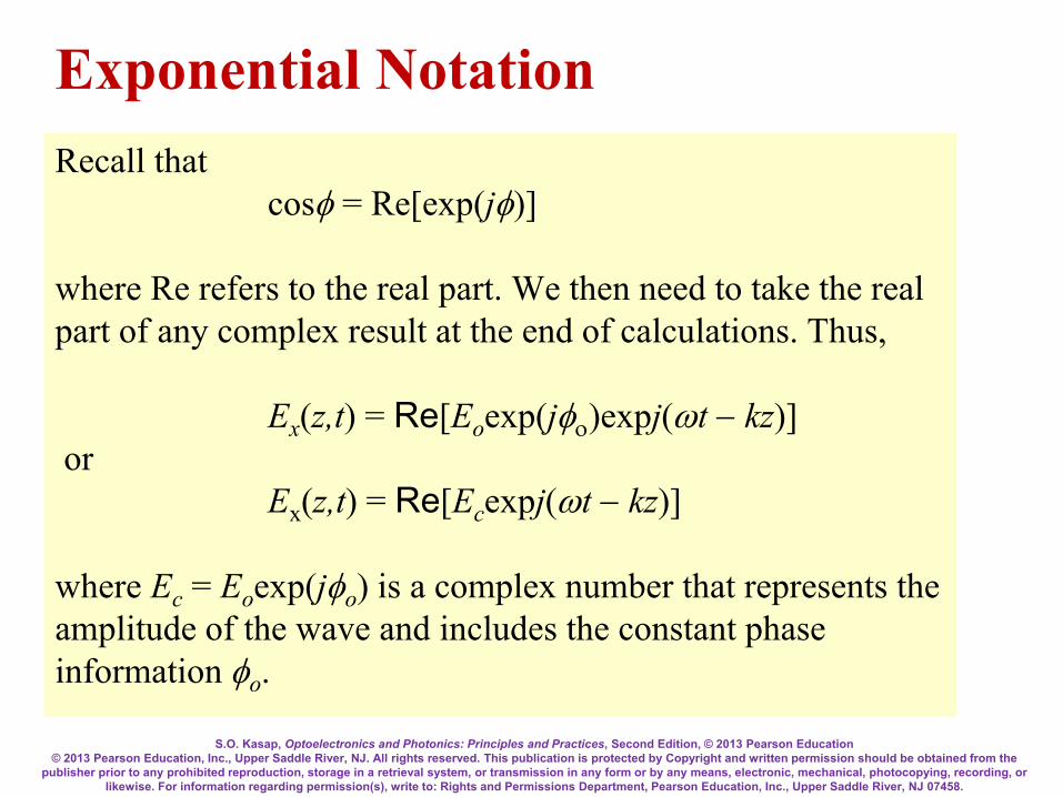
Recall that cosφ = Re[exp(jφ)] where Re refers to the real part. We then need to take the real part of any complex result at the end of calculations. Thus, Ex(z,t) = Re[Eoexp(jφο)expj(ωt − kz)] or Ex(z,t) = Re[Ecexpj(ωt − kz)] where Ec = Eoexp(jφo) is a complex number that represents the amplitude of the wave and includes the constant phase information φo.
Exponential Notation

S.O. Kasap, Optoelectronics and Photonics: Principles and Practices, Second Edition, © 2013 Pearson Education © 2013 Pearson Education, Inc., Upper Saddle River, NJ. All rights reserved. This publication is protected by Copyright and written permission should be obtained from the
publisher prior to any prohibited reproduction, storage in a retrieval system, or transmission in any form or by any means, electronic, mechanical, photocopying, recording, or likewise. For information regarding permission(s), write to: Rights and Permissions Department, Pearson Education, Inc., Upper Saddle River, NJ 07458.
Direction of propagation is indicated with a vector k, called the wave vector, whose magnitude is the propagation constant, k = 2π/λ. k is perpendicular to constant phase planes. When the electromagnetic (EM) wave is propagating along some arbitrary direction k, then the electric field E(r,t) at a point r on a plane perpendicular to k is E (r,t) = Eocos(ωt − k⋅r + φο) If propagation is along z, k⋅r becomes kz. In general, if k has components kx, ky and kz along x, y and z, then from the definition of the dot product, k⋅r = kxx + kyy + kzz.
Wave Vector or Propagation Vector

S.O. Kasap, Optoelectronics and Photonics: Principles and Practices, Second Edition, © 2013 Pearson Education © 2013 Pearson Education, Inc., Upper Saddle River, NJ. All rights reserved. This publication is protected by Copyright and written permission should be obtained from the
publisher prior to any prohibited reproduction, storage in a retrieval system, or transmission in any form or by any means, electronic, mechanical, photocopying, recording, or likewise. For information regarding permission(s), write to: Rights and Permissions Department, Pearson Education, Inc., Upper Saddle River, NJ 07458.
Wave Vector k
A traveling plane EM wave along a direction k
E (r,t) = Eocos(ωt − k⋅r + φο)

S.O. Kasap, Optoelectronics and Photonics: Principles and Practices, Second Edition, © 2013 Pearson Education © 2013 Pearson Education, Inc., Upper Saddle River, NJ. All rights reserved. This publication is protected by Copyright and written permission should be obtained from the
publisher prior to any prohibited reproduction, storage in a retrieval system, or transmission in any form or by any means, electronic, mechanical, photocopying, recording, or likewise. For information regarding permission(s), write to: Rights and Permissions Department, Pearson Education, Inc., Upper Saddle River, NJ 07458.
Maxwell’s Wave Equation
02
2
2
2
2
2
2
2
=∂∂
−∂∂
+∂∂
+∂∂
tE
zE
yE
xE
oro µεε
Ex = Eo cos(ωt − kz + φο)
A plane wave is a solution of Maxwell’s wave equation
Substitute into Maxwell’s Equation to show that this is a solution.

S.O. Kasap, Optoelectronics and Photonics: Principles and Practices, Second Edition, © 2013 Pearson Education © 2013 Pearson Education, Inc., Upper Saddle River, NJ. All rights reserved. This publication is protected by Copyright and written permission should be obtained from the
publisher prior to any prohibited reproduction, storage in a retrieval system, or transmission in any form or by any means, electronic, mechanical, photocopying, recording, or likewise. For information regarding permission(s), write to: Rights and Permissions Department, Pearson Education, Inc., Upper Saddle River, NJ 07458.
Spherical Wave
)cos( krtrAE −= ω

S.O. Kasap, Optoelectronics and Photonics: Principles and Practices, Second Edition, © 2013 Pearson Education © 2013 Pearson Education, Inc., Upper Saddle River, NJ. All rights reserved. This publication is protected by Copyright and written permission should be obtained from the
publisher prior to any prohibited reproduction, storage in a retrieval system, or transmission in any form or by any means, electronic, mechanical, photocopying, recording, or likewise. For information regarding permission(s), write to: Rights and Permissions Department, Pearson Education, Inc., Upper Saddle River, NJ 07458.
Refractive Index
When an EM wave is traveling in a dielectric medium, the oscillating electric field polarizes the molecules of the medium at the frequency of the wave The stronger is the interaction between the field and the dipoles, the slower is the propagation of the wave
S.O. Kasap, Optoelectronics and Photonics: Principles and Practices, Second Edition, © 2013 Pearson Education © 2013 Pearson Education, Inc., Upper Saddle River, NJ. All rights reserved. This publication is protected by Copyright and written permission should be obtained from the
publisher prior to any prohibited reproduction, storage in a retrieval system, or transmission in any form or by any means, electronic, mechanical, photocopying, recording, or likewise. For information regarding permission(s), write to: Rights and Permissions Department, Pearson Education, Inc., Upper Saddle River, NJ 07458.
Refractive Index

S.O. Kasap, Optoelectronics and Photonics: Principles and Practices, Second Edition, © 2013 Pearson Education © 2013 Pearson Education, Inc., Upper Saddle River, NJ. All rights reserved. This publication is protected by Copyright and written permission should be obtained from the
publisher prior to any prohibited reproduction, storage in a retrieval system, or transmission in any form or by any means, electronic, mechanical, photocopying, recording, or likewise. For information regarding permission(s), write to: Rights and Permissions Department, Pearson Education, Inc., Upper Saddle River, NJ 07458.
The relative permittivity εr measures the ease with which the medium becomes polarized and hence it indicates the extent of interaction between the field and the induced dipoles.
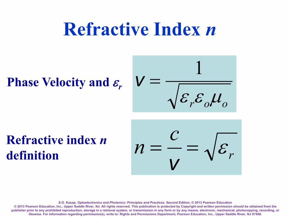
For an EM wave traveling in a nonmagnetic dielectric medium of relative permittivity εr, the phase velocity v is given by
Phase Velocity and εr
oor µεε1
=ν
S.O. Kasap, Optoelectronics and Photonics: Principles and Practices, Second Edition, © 2013 Pearson Education © 2013 Pearson Education, Inc., Upper Saddle River, NJ. All rights reserved. This publication is protected by Copyright and written permission should be obtained from the
publisher prior to any prohibited reproduction, storage in a retrieval system, or transmission in any form or by any means, electronic, mechanical, photocopying, recording, or likewise. For information regarding permission(s), write to: Rights and Permissions Department, Pearson Education, Inc., Upper Saddle River, NJ 07458.
Phase Velocity and εr
oor µεε1
=ν
rcn ε==v
Refractive index n definition
Refractive Index n

S.O. Kasap, Optoelectronics and Photonics: Principles and Practices, Second Edition, © 2013 Pearson Education © 2013 Pearson Education, Inc., Upper Saddle River, NJ. All rights reserved. This publication is protected by Copyright and written permission should be obtained from the
publisher prior to any prohibited reproduction, storage in a retrieval system, or transmission in any form or by any means, electronic, mechanical, photocopying, recording, or likewise. For information regarding permission(s), write to: Rights and Permissions Department, Pearson Education, Inc., Upper Saddle River, NJ 07458.
Optical frequencies Typical frequencies that are involved in optoelectronic devices are in the infrared (including far infrared), visible, and UV, and we generically refer to these frequencies as optical frequencies Somewhat arbitrary range: Roughly 1012 Hz to 1016 Hz

S.O. Kasap, Optoelectronics and Photonics: Principles and Practices, Second Edition, © 2013 Pearson Education © 2013 Pearson Education, Inc., Upper Saddle River, NJ. All rights reserved. This publication is protected by Copyright and written permission should be obtained from the
publisher prior to any prohibited reproduction, storage in a retrieval system, or transmission in any form or by any means, electronic, mechanical, photocopying, recording, or likewise. For information regarding permission(s), write to: Rights and Permissions Department, Pearson Education, Inc., Upper Saddle River, NJ 07458.
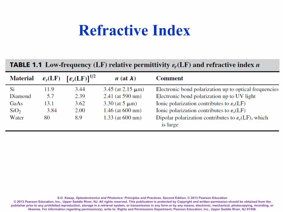
Low frequency (LF) relative permittivity εr(LF) and refractive index n.
S.O. Kasap, Optoelectronics and Photonics: Principles and Practices, Second Edition, © 2013 Pearson Education © 2013 Pearson Education, Inc., Upper Saddle River, NJ. All rights reserved. This publication is protected by Copyright and written permission should be obtained from the
publisher prior to any prohibited reproduction, storage in a retrieval system, or transmission in any form or by any means, electronic, mechanical, photocopying, recording, or likewise. For information regarding permission(s), write to: Rights and Permissions Department, Pearson Education, Inc., Upper Saddle River, NJ 07458.
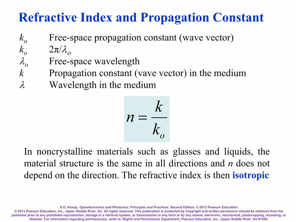
ko Free-space propagation constant (wave vector) ko 2π/λο λo Free-space wavelength k Propagation constant (vave vector) in the medium λ Wavelength in the medium
okkn =
In noncrystalline materials such as glasses and liquids, the material structure is the same in all directions and n does not depend on the direction. The refractive index is then isotropic
Refractive Index and Propagation Constant

S.O. Kasap, Optoelectronics and Photonics: Principles and Practices, Second Edition, © 2013 Pearson Education © 2013 Pearson Education, Inc., Upper Saddle River, NJ. All rights reserved. This publication is protected by Copyright and written permission should be obtained from the
publisher prior to any prohibited reproduction, storage in a retrieval system, or transmission in any form or by any means, electronic, mechanical, photocopying, recording, or likewise. For information regarding permission(s), write to: Rights and Permissions Department, Pearson Education, Inc., Upper Saddle River, NJ 07458.
Refractive Index and Wavelength
λmedium = λ /n
kmedium = nk

S.O. Kasap, Optoelectronics and Photonics: Principles and Practices, Second Edition, © 2013 Pearson Education © 2013 Pearson Education, Inc., Upper Saddle River, NJ. All rights reserved. This publication is protected by Copyright and written permission should be obtained from the
publisher prior to any prohibited reproduction, storage in a retrieval system, or transmission in any form or by any means, electronic, mechanical, photocopying, recording, or likewise. For information regarding permission(s), write to: Rights and Permissions Department, Pearson Education, Inc., Upper Saddle River, NJ 07458.
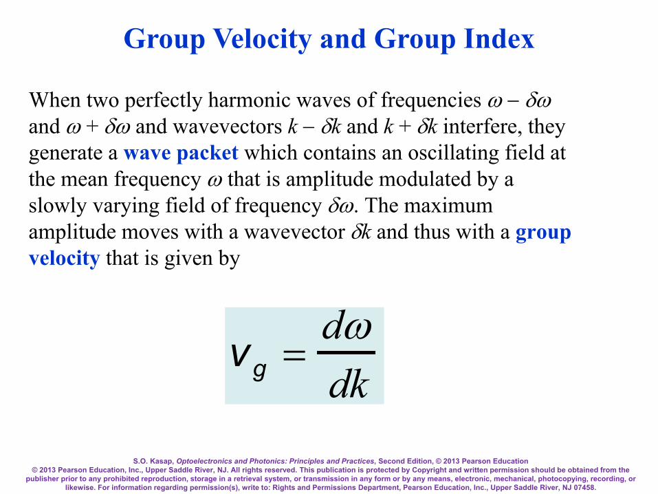
Group Velocity and Group Index
There are no perfect monochromatic waves We have to consider the way in which a group of waves differing slightly in wavelength travel along the z-direction
S.O. Kasap, Optoelectronics and Photonics: Principles and Practices, Second Edition, © 2013 Pearson Education © 2013 Pearson Education, Inc., Upper Saddle River, NJ. All rights reserved. This publication is protected by Copyright and written permission should be obtained from the
publisher prior to any prohibited reproduction, storage in a retrieval system, or transmission in any form or by any means, electronic, mechanical, photocopying, recording, or likewise. For information regarding permission(s), write to: Rights and Permissions Department, Pearson Education, Inc., Upper Saddle River, NJ 07458.
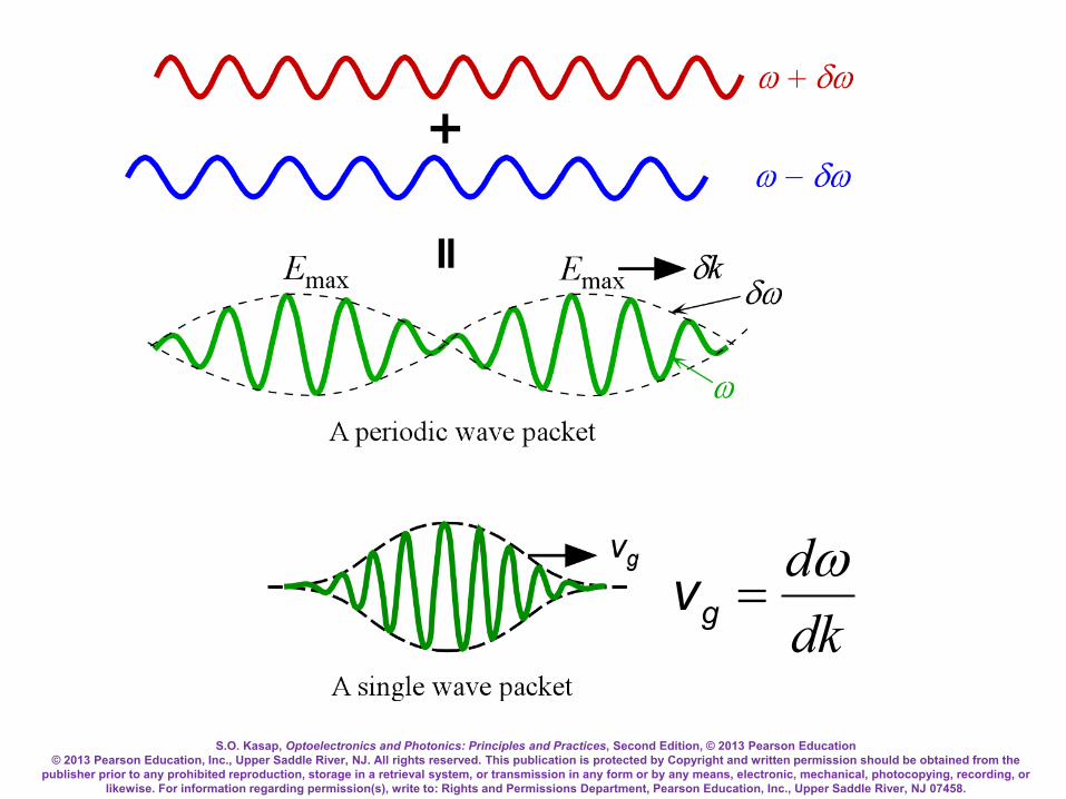
When two perfectly harmonic waves of frequencies ω − δω and ω + δω and wavevectors k − δk and k + δk interfere, they generate a wave packet which contains an oscillating field at the mean frequency ω that is amplitude modulated by a slowly varying field of frequency δω. The maximum amplitude moves with a wavevector δk and thus with a group velocity that is given by
vg =
dωdk
Group Velocity and Group Index

S.O. Kasap, Optoelectronics and Photonics: Principles and Practices, Second Edition, © 2013 Pearson Education © 2013 Pearson Education, Inc., Upper Saddle River, NJ. All rights reserved. This publication is protected by Copyright and written permission should be obtained from the
publisher prior to any prohibited reproduction, storage in a retrieval system, or transmission in any form or by any means, electronic, mechanical, photocopying, recording, or likewise. For information regarding permission(s), write to: Rights and Permissions Department, Pearson Education, Inc., Upper Saddle River, NJ 07458.
Two slightly different wavelength waves traveling in the same direction result in a wave packet that has an amplitude variation that travels at the group velocity.
Group Velocity
S.O. Kasap, Optoelectronics and Photonics: Principles and Practices, Second Edition, © 2013 Pearson Education © 2013 Pearson Education, Inc., Upper Saddle River, NJ. All rights reserved. This publication is protected by Copyright and written permission should be obtained from the
publisher prior to any prohibited reproduction, storage in a retrieval system, or transmission in any form or by any means, electronic, mechanical, photocopying, recording, or likewise. For information regarding permission(s), write to: Rights and Permissions Department, Pearson Education, Inc., Upper Saddle River, NJ 07458.
dkdω
=gv

S.O. Kasap, Optoelectronics and Photonics: Principles and Practices, Second Edition, © 2013 Pearson Education © 2013 Pearson Education, Inc., Upper Saddle River, NJ. All rights reserved. This publication is protected by Copyright and written permission should be obtained from the
publisher prior to any prohibited reproduction, storage in a retrieval system, or transmission in any form or by any means, electronic, mechanical, photocopying, recording, or likewise. For information regarding permission(s), write to: Rights and Permissions Department, Pearson Education, Inc., Upper Saddle River, NJ 07458.
Group Velocity Consider two sinusoidal waves that are close in frequency, that is, they have frequencies ω − δω and ω + δω. Their wavevectors will be k − δk and k + δk. The resultant wave is Ex(z,t) = Eocos[(ω − δω)t − (k − δk)z] + Eocos[(ω + δω)t − (k + δk)z] By using the trigonometric identity cosA + cosB = 2cos[1/2(A − B)]cos[1/2(A + B)] we arrive at Ex(z,t) = 2Eocos[(δω)t − (δk)z][cos(ωt − kz)]

S.O. Kasap, Optoelectronics and Photonics: Principles and Practices, Second Edition, © 2013 Pearson Education © 2013 Pearson Education, Inc., Upper Saddle River, NJ. All rights reserved. This publication is protected by Copyright and written permission should be obtained from the
publisher prior to any prohibited reproduction, storage in a retrieval system, or transmission in any form or by any means, electronic, mechanical, photocopying, recording, or likewise. For information regarding permission(s), write to: Rights and Permissions Department, Pearson Education, Inc., Upper Saddle River, NJ 07458.
This represents a sinusoidal wave of frequency ω . This is amplitude modulated by a very slowly varying sinusoidal of frequency δω. This system of waves, i.e. the modulation, travels along z at a speed determined by the modulating term, cos[(δω)t − (δk)z]. The maximum in the field occurs when [(δω)t − (δk)z] = 2mπ = constant (m is an integer), which travels with a velocity
dzdt
=δωδk
or dkdω
=gv
This is the group velocity of the waves because it determines the speed of propagation of the maximum electric field along z.
Ex(z,t) = 2Eocos[(δω)t − (δk)z][cos(ωt − kz)]

S.O. Kasap, Optoelectronics and Photonics: Principles and Practices, Second Edition, © 2013 Pearson Education © 2013 Pearson Education, Inc., Upper Saddle River, NJ. All rights reserved. This publication is protected by Copyright and written permission should be obtained from the
publisher prior to any prohibited reproduction, storage in a retrieval system, or transmission in any form or by any means, electronic, mechanical, photocopying, recording, or likewise. For information regarding permission(s), write to: Rights and Permissions Department, Pearson Education, Inc., Upper Saddle River, NJ 07458.
The group velocity therefore defines the speed with which energy or information is propagated.
ω = 2πc/λo and k = 2πn/λo, λo is the free space wavelength. Differentiate the above dω = −(2πc/λo
2)dλo
oo
ooo dddndndk λλ
λπλλπ
+−= )/2()/1(2 2
vg =
dωdk
oo
oo dddnndk λλ
λλπ
−−= )/2( 2
ooo
ooo
oo
ddnn
c
dddnn
dcdkd
λλλ
λλλπ
λλπω
−=
−−
−==
)/2(
)/2(
2
2
gv∴

S.O. Kasap, Optoelectronics and Photonics: Principles and Practices, Second Edition, © 2013 Pearson Education © 2013 Pearson Education, Inc., Upper Saddle River, NJ. All rights reserved. This publication is protected by Copyright and written permission should be obtained from the
publisher prior to any prohibited reproduction, storage in a retrieval system, or transmission in any form or by any means, electronic, mechanical, photocopying, recording, or likewise. For information regarding permission(s), write to: Rights and Permissions Department, Pearson Education, Inc., Upper Saddle River, NJ 07458.
where n = n(λ) is a function of the wavelength. The group velocity vg in a medium is given by,
vg(medium) =dωdk
=c
n − λdndλ
This can be written as
vg(medium) =
cNg
Group Velocity and Group Index

S.O. Kasap, Optoelectronics and Photonics: Principles and Practices, Second Edition, © 2013 Pearson Education © 2013 Pearson Education, Inc., Upper Saddle River, NJ. All rights reserved. This publication is protected by Copyright and written permission should be obtained from the
publisher prior to any prohibited reproduction, storage in a retrieval system, or transmission in any form or by any means, electronic, mechanical, photocopying, recording, or likewise. For information regarding permission(s), write to: Rights and Permissions Department, Pearson Education, Inc., Upper Saddle River, NJ 07458.
Ng = n − λ
dndλ
is defined as the group index of the medium In general, for many materials the refractive index n and hence the group index Ng depend on the wavelength of light. Such materials are called dispersive
Group Index

S.O. Kasap, Optoelectronics and Photonics: Principles and Practices, Second Edition, © 2013 Pearson Education © 2013 Pearson Education, Inc., Upper Saddle River, NJ. All rights reserved. This publication is protected by Copyright and written permission should be obtained from the
publisher prior to any prohibited reproduction, storage in a retrieval system, or transmission in any form or by any means, electronic, mechanical, photocopying, recording, or likewise. For information regarding permission(s), write to: Rights and Permissions Department, Pearson Education, Inc., Upper Saddle River, NJ 07458.
Refractive index n and the group index Ng of pure SiO2 (silica) glass as a function of wavelength.
S.O. Kasap, Optoelectronics and Photonics: Principles and Practices, Second Edition, © 2013 Pearson Education © 2013 Pearson Education, Inc., Upper Saddle River, NJ. All rights reserved. This publication is protected by Copyright and written permission should be obtained from the
publisher prior to any prohibited reproduction, storage in a retrieval system, or transmission in any form or by any means, electronic, mechanical, photocopying, recording, or likewise. For information regarding permission(s), write to: Rights and Permissions Department, Pearson Education, Inc., Upper Saddle River, NJ 07458.
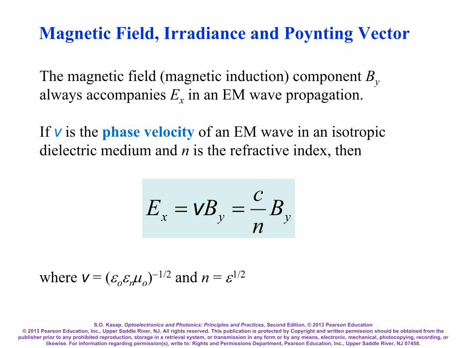
Magnetic Field, Irradiance and Poynting Vector
The magnetic field (magnetic induction) component By always accompanies Ex in an EM wave propagation. If v is the phase velocity of an EM wave in an isotropic dielectric medium and n is the refractive index, then
yyx BncBE == v
where v = (εoεrµo)−1/2 and n = ε1/2
S.O. Kasap, Optoelectronics and Photonics: Principles and Practices, Second Edition, © 2013 Pearson Education © 2013 Pearson Education, Inc., Upper Saddle River, NJ. All rights reserved. This publication is protected by Copyright and written permission should be obtained from the
publisher prior to any prohibited reproduction, storage in a retrieval system, or transmission in any form or by any means, electronic, mechanical, photocopying, recording, or likewise. For information regarding permission(s), write to: Rights and Permissions Department, Pearson Education, Inc., Upper Saddle River, NJ 07458.
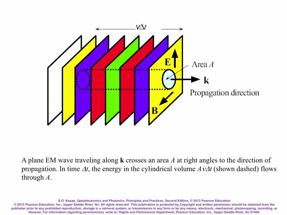
A plane EM wave traveling along k crosses an area A at right angles to the direction of propagation. In time ∆t, the energy in the cylindrical volume Aν∆t (shown dashed) flows through A.

S.O. Kasap, Optoelectronics and Photonics: Principles and Practices, Second Edition, © 2013 Pearson Education © 2013 Pearson Education, Inc., Upper Saddle River, NJ. All rights reserved. This publication is protected by Copyright and written permission should be obtained from the
publisher prior to any prohibited reproduction, storage in a retrieval system, or transmission in any form or by any means, electronic, mechanical, photocopying, recording, or likewise. For information regarding permission(s), write to: Rights and Permissions Department, Pearson Education, Inc., Upper Saddle River, NJ 07458.
As the EM wave propagates in the direction of the wavevector k, there is an energy flow in this direction. The wave brings with it electromagnetic energy. The energy densities in the Ex and By fields are the same,
22
21
21
yo
xro BEµ
εε =
The total energy density in the wave is therefore εoεrEx2.
Energy Density in an EM Wave

S.O. Kasap, Optoelectronics and Photonics: Principles and Practices, Second Edition, © 2013 Pearson Education © 2013 Pearson Education, Inc., Upper Saddle River, NJ. All rights reserved. This publication is protected by Copyright and written permission should be obtained from the
publisher prior to any prohibited reproduction, storage in a retrieval system, or transmission in any form or by any means, electronic, mechanical, photocopying, recording, or likewise. For information regarding permission(s), write to: Rights and Permissions Department, Pearson Education, Inc., Upper Saddle River, NJ 07458.
If S is the EM power flow per unit area, S = Energy flow per unit time per unit area
yxroxroxro BEE
tAEtAS εεεεεε 22
2))(( vvv==
∆∆
=
In an isotropic medium, the energy flow is in the direction of wave propagation. If we use the vectors E and B to represent the electric and magnetic fields in the EM wave, then the EM power flow per unit area can be written as
Poynting Vector and EM Power Flow
S = v2εoεrE×B

S.O. Kasap, Optoelectronics and Photonics: Principles and Practices, Second Edition, © 2013 Pearson Education © 2013 Pearson Education, Inc., Upper Saddle River, NJ. All rights reserved. This publication is protected by Copyright and written permission should be obtained from the
publisher prior to any prohibited reproduction, storage in a retrieval system, or transmission in any form or by any means, electronic, mechanical, photocopying, recording, or likewise. For information regarding permission(s), write to: Rights and Permissions Department, Pearson Education, Inc., Upper Saddle River, NJ 07458.
where S, called the Poynting vector, represents the energy flow per unit time per unit area in a direction determined by E×B (direction of propagation). Its magnitude, power flow per unit area, is called the irradiance (instantaneous irradiance, or intensity). The average irradiance is
221
average oro ESI εεv==
Poynting Vector and Intensity
S.O. Kasap, Optoelectronics and Photonics: Principles and Practices, Second Edition, © 2013 Pearson Education © 2013 Pearson Education, Inc., Upper Saddle River, NJ. All rights reserved. This publication is protected by Copyright and written permission should be obtained from the
publisher prior to any prohibited reproduction, storage in a retrieval system, or transmission in any form or by any means, electronic, mechanical, photocopying, recording, or likewise. For information regarding permission(s), write to: Rights and Permissions Department, Pearson Education, Inc., Upper Saddle River, NJ 07458.
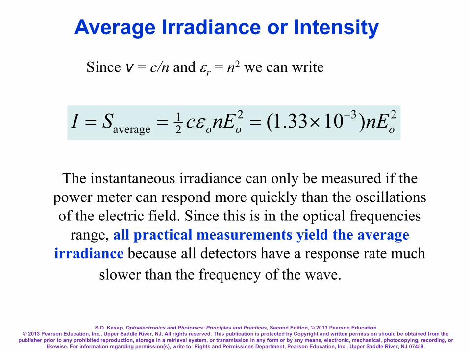
Since v = c/n and εr = n2 we can write
23221
average )1033.1( ooo nEnEcSI −×=== ε
The instantaneous irradiance can only be measured if the power meter can respond more quickly than the oscillations of the electric field. Since this is in the optical frequencies
range, all practical measurements yield the average irradiance because all detectors have a response rate much
slower than the frequency of the wave.
Average Irradiance or Intensity

S.O. Kasap, Optoelectronics and Photonics: Principles and Practices, Second Edition, © 2013 Pearson Education © 2013 Pearson Education, Inc., Upper Saddle River, NJ. All rights reserved. This publication is protected by Copyright and written permission should be obtained from the
publisher prior to any prohibited reproduction, storage in a retrieval system, or transmission in any form or by any means, electronic, mechanical, photocopying, recording, or likewise. For information regarding permission(s), write to: Rights and Permissions Department, Pearson Education, Inc., Upper Saddle River, NJ 07458.
Irradiance of a Spherical Wave
24 rPI o
π=
Perfect spherical wave

S.O. Kasap, Optoelectronics and Photonics: Principles and Practices, Second Edition, © 2013 Pearson Education © 2013 Pearson Education, Inc., Upper Saddle River, NJ. All rights reserved. This publication is protected by Copyright and written permission should be obtained from the
publisher prior to any prohibited reproduction, storage in a retrieval system, or transmission in any form or by any means, electronic, mechanical, photocopying, recording, or likewise. For information regarding permission(s), write to: Rights and Permissions Department, Pearson Education, Inc., Upper Saddle River, NJ 07458.
Spherical wave front
9A4AAA
r
2r
3r
OSource
Po
Irradiance of a Spherical Wave
24 rPI o
π=

S.O. Kasap, Optoelectronics and Photonics: Principles and Practices, Second Edition, © 2013 Pearson Education © 2013 Pearson Education, Inc., Upper Saddle River, NJ. All rights reserved. This publication is protected by Copyright and written permission should be obtained from the
publisher prior to any prohibited reproduction, storage in a retrieval system, or transmission in any form or by any means, electronic, mechanical, photocopying, recording, or likewise. For information regarding permission(s), write to: Rights and Permissions Department, Pearson Education, Inc., Upper Saddle River, NJ 07458.
A Gaussian Beam
I(r,z) = [2P/(πw2)]exp(−2r2/w2)
θo = w/z = λ/(πwo) 2θo = Far field divergence

S.O. Kasap, Optoelectronics and Photonics: Principles and Practices, Second Edition, © 2013 Pearson Education © 2013 Pearson Education, Inc., Upper Saddle River, NJ. All rights reserved. This publication is protected by Copyright and written permission should be obtained from the
publisher prior to any prohibited reproduction, storage in a retrieval system, or transmission in any form or by any means, electronic, mechanical, photocopying, recording, or likewise. For information regarding permission(s), write to: Rights and Permissions Department, Pearson Education, Inc., Upper Saddle River, NJ 07458.
Power in a Gaussian Beam
])/(2exp[)0()( 222 wrIrI −=
865.02)(
2)(
0
0 =
∫
∫∞
rdrrI
rdrrIw
π
πFraction of optical power
within 2w =
Area of a circular thin strip (annulus) with radius r is 2πrdr. Power passing through this strip is proportional to I(r) (2πr)dr
and

S.O. Kasap, Optoelectronics and Photonics: Principles and Practices, Second Edition, © 2013 Pearson Education © 2013 Pearson Education, Inc., Upper Saddle River, NJ. All rights reserved. This publication is protected by Copyright and written permission should be obtained from the
publisher prior to any prohibited reproduction, storage in a retrieval system, or transmission in any form or by any means, electronic, mechanical, photocopying, recording, or likewise. For information regarding permission(s), write to: Rights and Permissions Department, Pearson Education, Inc., Upper Saddle River, NJ 07458.
Snell’s Law or Descartes’s Law?

S.O. Kasap, Optoelectronics and Photonics: Principles and Practices, Second Edition, © 2013 Pearson Education © 2013 Pearson Education, Inc., Upper Saddle River, NJ. All rights reserved. This publication is protected by Copyright and written permission should be obtained from the
publisher prior to any prohibited reproduction, storage in a retrieval system, or transmission in any form or by any means, electronic, mechanical, photocopying, recording, or likewise. For information regarding permission(s), write to: Rights and Permissions Department, Pearson Education, Inc., Upper Saddle River, NJ 07458.
Snell's Law
1
2
sinsin
nn
t
i =θθ

S.O. Kasap, Optoelectronics and Photonics: Principles and Practices, Second Edition, © 2013 Pearson Education © 2013 Pearson Education, Inc., Upper Saddle River, NJ. All rights reserved. This publication is protected by Copyright and written permission should be obtained from the
publisher prior to any prohibited reproduction, storage in a retrieval system, or transmission in any form or by any means, electronic, mechanical, photocopying, recording, or likewise. For information regarding permission(s), write to: Rights and Permissions Department, Pearson Education, Inc., Upper Saddle River, NJ 07458.
A light wave traveling in a medium with a greater refractive index (n1 > n2) suffers reflection and refraction at the boundary. (Notice that λt is slightly longer than λ.)
Derivation of Snell’s Law

S.O. Kasap, Optoelectronics and Photonics: Principles and Practices, Second Edition, © 2013 Pearson Education © 2013 Pearson Education, Inc., Upper Saddle River, NJ. All rights reserved. This publication is protected by Copyright and written permission should be obtained from the
publisher prior to any prohibited reproduction, storage in a retrieval system, or transmission in any form or by any means, electronic, mechanical, photocopying, recording, or likewise. For information regarding permission(s), write to: Rights and Permissions Department, Pearson Education, Inc., Upper Saddle River, NJ 07458.
We can use constructive interference to show that there can only be one reflected wave which occurs at an angle equal to the incidence angle. The two waves along Ai and Bi are in phase. When these waves are reflected to become waves Ar and Br then they must still be in phase, otherwise they will interfere destructively and destroy each other. The only way the two waves can stay in phase is if θr = θi. All other angles lead to the waves Ar and Br being out of phase and interfering destructively.
Snell’s Law

S.O. Kasap, Optoelectronics and Photonics: Principles and Practices, Second Edition, © 2013 Pearson Education © 2013 Pearson Education, Inc., Upper Saddle River, NJ. All rights reserved. This publication is protected by Copyright and written permission should be obtained from the
publisher prior to any prohibited reproduction, storage in a retrieval system, or transmission in any form or by any means, electronic, mechanical, photocopying, recording, or likewise. For information regarding permission(s), write to: Rights and Permissions Department, Pearson Education, Inc., Upper Saddle River, NJ 07458.
Unless the two waves at A′ and B′ still have the same phase, there will be no transmitted wave. A′ and B′ points on the front are only in phase for one particular transmitted angle, θt. It takes time t for the phase at B on wave Bi to reach B′ BB′ = v1t = ct/n1 During this time t, the phase A has progressed to A′ AA′ = v2t = ct/n2 A′ and B′ belong to the same front just like A and B so that AB is perpendicular to ki in medium 1 and A′B′ is perpendicular to kt in medium 2. From geometrical considerations, AB′ = BB′/sinθi and AB′ = AA′/sinθt so that
Snell’s Law

S.O. Kasap, Optoelectronics and Photonics: Principles and Practices, Second Edition, © 2013 Pearson Education © 2013 Pearson Education, Inc., Upper Saddle River, NJ. All rights reserved. This publication is protected by Copyright and written permission should be obtained from the
publisher prior to any prohibited reproduction, storage in a retrieval system, or transmission in any form or by any means, electronic, mechanical, photocopying, recording, or likewise. For information regarding permission(s), write to: Rights and Permissions Department, Pearson Education, Inc., Upper Saddle River, NJ 07458.
or A ′ B =
v1tsinθ i
=v2t
sinθ t
sinθi
sinθt
=v1
v2
=n2
n1
This is Snell's law which relates the angles of incidence and refraction to the refractive indices of the media.
ti nn θθ sinsin 21 =
constantsin =θn

S.O. Kasap, Optoelectronics and Photonics: Principles and Practices, Second Edition, © 2013 Pearson Education © 2013 Pearson Education, Inc., Upper Saddle River, NJ. All rights reserved. This publication is protected by Copyright and written permission should be obtained from the
publisher prior to any prohibited reproduction, storage in a retrieval system, or transmission in any form or by any means, electronic, mechanical, photocopying, recording, or likewise. For information regarding permission(s), write to: Rights and Permissions Department, Pearson Education, Inc., Upper Saddle River, NJ 07458.
When n1 > n2 then obviously the transmitted angle is greater than the incidence angle as apparent in the figure. When the refraction angle θt reaches 90°, the incidence angle is called
the critical angle θc which is given by
ti nn θθ sinsin 21 =
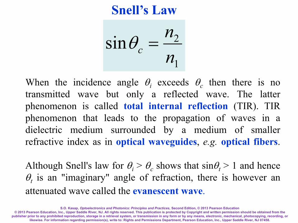
1
2sinnn
c =θ
S.O. Kasap, Optoelectronics and Photonics: Principles and Practices, Second Edition, © 2013 Pearson Education © 2013 Pearson Education, Inc., Upper Saddle River, NJ. All rights reserved. This publication is protected by Copyright and written permission should be obtained from the
publisher prior to any prohibited reproduction, storage in a retrieval system, or transmission in any form or by any means, electronic, mechanical, photocopying, recording, or likewise. For information regarding permission(s), write to: Rights and Permissions Department, Pearson Education, Inc., Upper Saddle River, NJ 07458.
When the incidence angle θi exceeds θc then there is no transmitted wave but only a reflected wave. The latter phenomenon is called total internal reflection (TIR). TIR phenomenon that leads to the propagation of waves in a dielectric medium surrounded by a medium of smaller refractive index as in optical waveguides, e.g. optical fibers.
Although Snell's law for θi > θc shows that sinθt > 1 and hence θt is an "imaginary" angle of refraction, there is however an attenuated wave called the evanescent wave.
1
2sinnn
c =θ
Snell’s Law

S.O. Kasap, Optoelectronics and Photonics: Principles and Practices, Second Edition, © 2013 Pearson Education © 2013 Pearson Education, Inc., Upper Saddle River, NJ. All rights reserved. This publication is protected by Copyright and written permission should be obtained from the
publisher prior to any prohibited reproduction, storage in a retrieval system, or transmission in any form or by any means, electronic, mechanical, photocopying, recording, or likewise. For information regarding permission(s), write to: Rights and Permissions Department, Pearson Education, Inc., Upper Saddle River, NJ 07458.
Fresnel's Equations
Light wave traveling in a more dense medium strikes a less dense medium. The plane of incidence is the plane of the paper and is perpendicular to the flat interface between the two media. The electric field is normal to the direction of
propagation. It can be resolved into perpendicular and parallel components.

S.O. Kasap, Optoelectronics and Photonics: Principles and Practices, Second Edition, © 2013 Pearson Education © 2013 Pearson Education, Inc., Upper Saddle River, NJ. All rights reserved. This publication is protected by Copyright and written permission should be obtained from the
publisher prior to any prohibited reproduction, storage in a retrieval system, or transmission in any form or by any means, electronic, mechanical, photocopying, recording, or likewise. For information regarding permission(s), write to: Rights and Permissions Department, Pearson Education, Inc., Upper Saddle River, NJ 07458.
We find a special incidence angle, labeled as θp, by solving the Fresnel equation for r// = 0. The field in the reflected wave is then always perpendicular to the plane of incidence and hence well-defined. This special angle is called the polarization angle or Brewster's angle,
1
2tannn
p =θ
Reflection and Polarization Angle
S.O. Kasap, Optoelectronics and Photonics: Principles and Practices, Second Edition, © 2013 Pearson Education © 2013 Pearson Education, Inc., Upper Saddle River, NJ. All rights reserved. This publication is protected by Copyright and written permission should be obtained from the
publisher prior to any prohibited reproduction, storage in a retrieval system, or transmission in any form or by any means, electronic, mechanical, photocopying, recording, or likewise. For information regarding permission(s), write to: Rights and Permissions Department, Pearson Education, Inc., Upper Saddle River, NJ 07458.
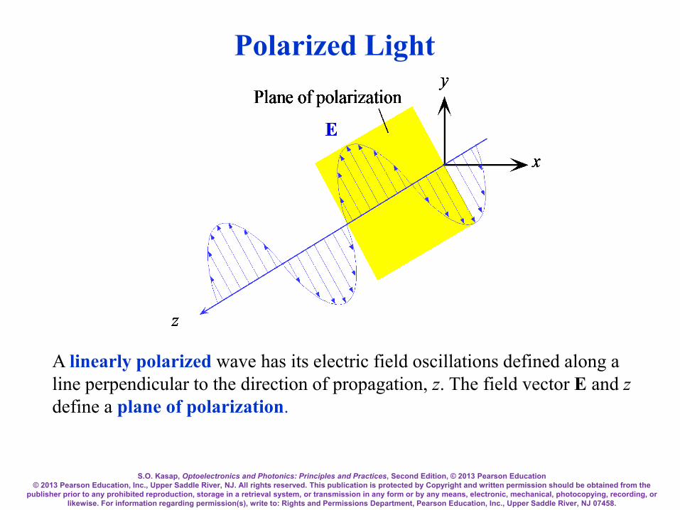
Polarized Light
A linearly polarized wave has its electric field oscillations defined along a line perpendicular to the direction of propagation, z. The field vector E and z define a plane of polarization.

S.O. Kasap, Optoelectronics and Photonics: Principles and Practices, Second Edition, © 2013 Pearson Education © 2013 Pearson Education, Inc., Upper Saddle River, NJ. All rights reserved. This publication is protected by Copyright and written permission should be obtained from the
publisher prior to any prohibited reproduction, storage in a retrieval system, or transmission in any form or by any means, electronic, mechanical, photocopying, recording, or likewise. For information regarding permission(s), write to: Rights and Permissions Department, Pearson Education, Inc., Upper Saddle River, NJ 07458.
Brewster's angle

S.O. Kasap, Optoelectronics and Photonics: Principles and Practices, Second Edition, © 2013 Pearson Education © 2013 Pearson Education, Inc., Upper Saddle River, NJ. All rights reserved. This publication is protected by Copyright and written permission should be obtained from the
publisher prior to any prohibited reproduction, storage in a retrieval system, or transmission in any form or by any means, electronic, mechanical, photocopying, recording, or likewise. For information regarding permission(s), write to: Rights and Permissions Department, Pearson Education, Inc., Upper Saddle River, NJ 07458.
In linearly polarized light, however, the field oscillations are contained within a well defined plane. Light emitted from many light sources such as a tungsten light bulb or an LED diode is unpolarized and the field is randomly oriented in a direction that is perpendicular to the direction of propagation. At the critical angle and beyond (past 44° in the figure), i.e. when θi ≥ θc, the magnitudes of both r// and r⊥ go to unity so that the reflected wave has the same amplitude as the incident wave. The incident wave has suffered total internal reflection, TIR.
Total Internal Reflection
S.O. Kasap, Optoelectronics and Photonics: Principles and Practices, Second Edition, © 2013 Pearson Education © 2013 Pearson Education, Inc., Upper Saddle River, NJ. All rights reserved. This publication is protected by Copyright and written permission should be obtained from the
publisher prior to any prohibited reproduction, storage in a retrieval system, or transmission in any form or by any means, electronic, mechanical, photocopying, recording, or likewise. For information regarding permission(s), write to: Rights and Permissions Department, Pearson Education, Inc., Upper Saddle River, NJ 07458.
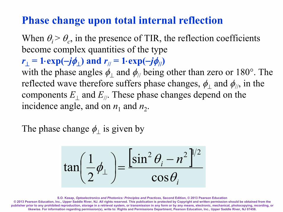
When θi > θc, in the presence of TIR, the reflection coefficients become complex quantities of the type r⊥ = 1⋅exp(−jφ⊥) and r// = 1⋅exp(−jφ//) with the phase angles φ⊥ and φ// being other than zero or 180°. The reflected wave therefore suffers phase changes, φ⊥ and φ//, in the components E⊥ and E//. These phase changes depend on the incidence angle, and on n1 and n2. The phase change φ⊥ is given by
[ ]i
i nθ
θφcos
sin21tan
2122 −=
⊥
Phase change upon total internal reflection

S.O. Kasap, Optoelectronics and Photonics: Principles and Practices, Second Edition, © 2013 Pearson Education © 2013 Pearson Education, Inc., Upper Saddle River, NJ. All rights reserved. This publication is protected by Copyright and written permission should be obtained from the
publisher prior to any prohibited reproduction, storage in a retrieval system, or transmission in any form or by any means, electronic, mechanical, photocopying, recording, or likewise. For information regarding permission(s), write to: Rights and Permissions Department, Pearson Education, Inc., Upper Saddle River, NJ 07458.
For the E// component, the phase change φ// is given by
( ) [ ]i
i
nnθ
θφcos
sintan 2
2/122
21
//21 −
=π+
Phase change upon total internal reflection

S.O. Kasap, Optoelectronics and Photonics: Principles and Practices, Second Edition, © 2013 Pearson Education © 2013 Pearson Education, Inc., Upper Saddle River, NJ. All rights reserved. This publication is protected by Copyright and written permission should be obtained from the
publisher prior to any prohibited reproduction, storage in a retrieval system, or transmission in any form or by any means, electronic, mechanical, photocopying, recording, or likewise. For information regarding permission(s), write to: Rights and Permissions Department, Pearson Education, Inc., Upper Saddle River, NJ 07458.
The reflection coefficients r// and r⊥ versus angle of incidence θi for n1 = 1.00 and n2 = 1.44.
External Reflection

S.O. Kasap, Optoelectronics and Photonics: Principles and Practices, Second Edition, © 2013 Pearson Education © 2013 Pearson Education, Inc., Upper Saddle River, NJ. All rights reserved. This publication is protected by Copyright and written permission should be obtained from the
publisher prior to any prohibited reproduction, storage in a retrieval system, or transmission in any form or by any means, electronic, mechanical, photocopying, recording, or likewise. For information regarding permission(s), write to: Rights and Permissions Department, Pearson Education, Inc., Upper Saddle River, NJ 07458.
In internal reflection (n1 > n2), the amplitude of the reflected wave from TIR is equal to the amplitude of the incident wave but its phase has shifted. What happens to the transmitted wave when θi > θc? According to the boundary conditions, there must still be an electric field in medium 2, otherwise, the boundary conditions cannot be satisfied. When θi > θc, the field in medium 2 is attenuated (decreases with y, and is called the evanescent wave.
Evanescent Wave

S.O. Kasap, Optoelectronics and Photonics: Principles and Practices, Second Edition, © 2013 Pearson Education © 2013 Pearson Education, Inc., Upper Saddle River, NJ. All rights reserved. This publication is protected by Copyright and written permission should be obtained from the
publisher prior to any prohibited reproduction, storage in a retrieval system, or transmission in any form or by any means, electronic, mechanical, photocopying, recording, or likewise. For information regarding permission(s), write to: Rights and Permissions Department, Pearson Education, Inc., Upper Saddle River, NJ 07458.
When θi > θc, for a plane wave that is reflected, there is an evanescent wave at the boundary propagating along z.

S.O. Kasap, Optoelectronics and Photonics: Principles and Practices, Second Edition, © 2013 Pearson Education © 2013 Pearson Education, Inc., Upper Saddle River, NJ. All rights reserved. This publication is protected by Copyright and written permission should be obtained from the
publisher prior to any prohibited reproduction, storage in a retrieval system, or transmission in any form or by any means, electronic, mechanical, photocopying, recording, or likewise. For information regarding permission(s), write to: Rights and Permissions Department, Pearson Education, Inc., Upper Saddle River, NJ 07458.
)(exp),,( 2, zktjtzyE iz
yt −∝ −
⊥ ωαe
where kiz = kisinθi is the wavevector of the incident wave along the z-axis, and α2 is an attenuation coefficient for the electric field penetrating into medium 2
2/1
22
2
122 1sin2
−
= in
nn θλπα
Evanescent wave when plane waves are incident and reflected
S.O. Kasap, Optoelectronics and Photonics: Principles and Practices, Second Edition, © 2013 Pearson Education © 2013 Pearson Education, Inc., Upper Saddle River, NJ. All rights reserved. This publication is protected by Copyright and written permission should be obtained from the
publisher prior to any prohibited reproduction, storage in a retrieval system, or transmission in any form or by any means, electronic, mechanical, photocopying, recording, or likewise. For information regarding permission(s), write to: Rights and Permissions Department, Pearson Education, Inc., Upper Saddle River, NJ 07458.
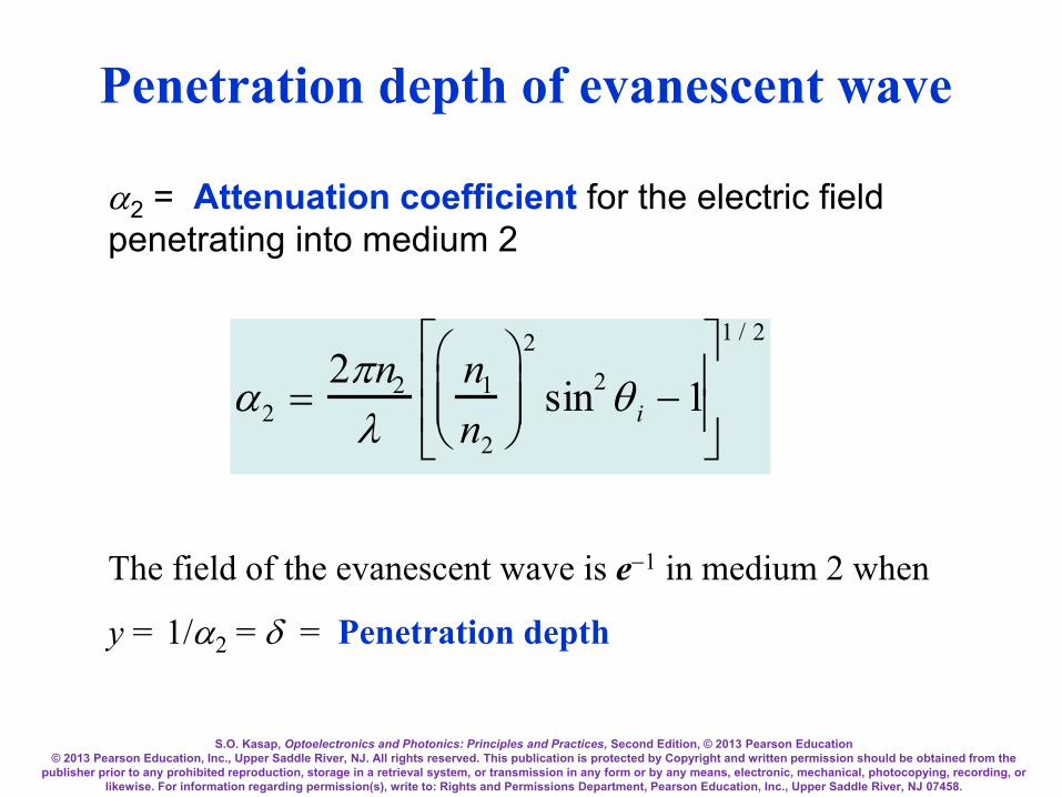
Penetration depth of evanescent wave
α2 = Attenuation coefficient for the electric field penetrating into medium 2
α2 =2πn2
λn1
n2
2
sin2 θ i −1
1 / 2
The field of the evanescent wave is e−1 in medium 2 when
y = 1/α2 = δ = Penetration depth

S.O. Kasap, Optoelectronics and Photonics: Principles and Practices, Second Edition, © 2013 Pearson Education © 2013 Pearson Education, Inc., Upper Saddle River, NJ. All rights reserved. This publication is protected by Copyright and written permission should be obtained from the
publisher prior to any prohibited reproduction, storage in a retrieval system, or transmission in any form or by any means, electronic, mechanical, photocopying, recording, or likewise. For information regarding permission(s), write to: Rights and Permissions Department, Pearson Education, Inc., Upper Saddle River, NJ 07458.
n2
n1 > n2
d
n1
A
B
C
ki
kr
kt
Optically tunneled light
θi > θc
Incident light Reflected light
y
E
When medium B is thin (thickness d is small), the field penetrates from the AB interface into medium B and reaches BC interface, and gives rise to a transmitted wave in medium C. The effect is the tunneling of the incident beam in A through B to C. The maximum field Emax of the evanescent wave in B decays in B along y and but is finite at the BC boundary and excites the transmitted wave.
Optical Tunneling

S.O. Kasap, Optoelectronics and Photonics: Principles and Practices, Second Edition, © 2013 Pearson Education © 2013 Pearson Education, Inc., Upper Saddle River, NJ. All rights reserved. This publication is protected by Copyright and written permission should be obtained from the
publisher prior to any prohibited reproduction, storage in a retrieval system, or transmission in any form or by any means, electronic, mechanical, photocopying, recording, or likewise. For information regarding permission(s), write to: Rights and Permissions Department, Pearson Education, Inc., Upper Saddle River, NJ 07458.
Optical Tunneling
Light propagation along an optical guide by total internal reflections
Coupling of laser light into a thin layer - optical guide - using a prism. The
light propagates along the thin layer.

S.O. Kasap, Optoelectronics and Photonics: Principles and Practices, Second Edition, © 2013 Pearson Education © 2013 Pearson Education, Inc., Upper Saddle River, NJ. All rights reserved. This publication is protected by Copyright and written permission should be obtained from the
publisher prior to any prohibited reproduction, storage in a retrieval system, or transmission in any form or by any means, electronic, mechanical, photocopying, recording, or likewise. For information regarding permission(s), write to: Rights and Permissions Department, Pearson Education, Inc., Upper Saddle River, NJ 07458.
Light approaches the boundary from the lower index side, n1 < n2 This is external reflection. Light becomes reflected by the surface of an optically denser (higher refractive index) medium. r⊥ and r// depend on the incidence angle θi. At normal incidence, r⊥ and r// are negative. In external reflection at normal incidence there is a phase shift of 180°. r// goes through zero at the Brewster angle, θp. At θp, the reflected wave is polarized in the E⊥ component only. Transmitted light in both internal reflection (when θi < θc) and external reflection does not experience a phase shift.
External Reflection

S.O. Kasap, Optoelectronics and Photonics: Principles and Practices, Second Edition, © 2013 Pearson Education © 2013 Pearson Education, Inc., Upper Saddle River, NJ. All rights reserved. This publication is protected by Copyright and written permission should be obtained from the
publisher prior to any prohibited reproduction, storage in a retrieval system, or transmission in any form or by any means, electronic, mechanical, photocopying, recording, or likewise. For information regarding permission(s), write to: Rights and Permissions Department, Pearson Education, Inc., Upper Saddle River, NJ 07458.
Intensity, Reflectance and Transmittance
Reflectance R measures the intensity of the reflected light with respect to that of the incident light and can be defined separately for electric field components parallel and perpendicular to the plane of incidence. The reflectances R⊥ and R// are defined by
2
2
2
⊥
⊥
⊥⊥ == rR
,
,
io
ro
E
E and 2
//2
//,
2
//,// rR ==
io
ro
E
E

S.O. Kasap, Optoelectronics and Photonics: Principles and Practices, Second Edition, © 2013 Pearson Education © 2013 Pearson Education, Inc., Upper Saddle River, NJ. All rights reserved. This publication is protected by Copyright and written permission should be obtained from the
publisher prior to any prohibited reproduction, storage in a retrieval system, or transmission in any form or by any means, electronic, mechanical, photocopying, recording, or likewise. For information regarding permission(s), write to: Rights and Permissions Department, Pearson Education, Inc., Upper Saddle River, NJ 07458.
At normal incidence
2
21
21//
+−
=== ⊥ nnnnRRR
Since a glass medium has a refractive index of around 1.5 this means that typically 4% of the incident radiation on an air-glass surface will be reflected back.

S.O. Kasap, Optoelectronics and Photonics: Principles and Practices, Second Edition, © 2013 Pearson Education © 2013 Pearson Education, Inc., Upper Saddle River, NJ. All rights reserved. This publication is protected by Copyright and written permission should be obtained from the
publisher prior to any prohibited reproduction, storage in a retrieval system, or transmission in any form or by any means, electronic, mechanical, photocopying, recording, or likewise. For information regarding permission(s), write to: Rights and Permissions Department, Pearson Education, Inc., Upper Saddle River, NJ 07458.
Transmittance T relates the intensity of the transmitted wave to that of the incident wave in a similar fashion to the
reflectance.
However the transmitted wave is in a different medium and further its direction with respect to the boundary is also
different due to refraction.
For normal incidence, the incident and transmitted beams are normal so that the equations are simple:
Transmittance

S.O. Kasap, Optoelectronics and Photonics: Principles and Practices, Second Edition, © 2013 Pearson Education © 2013 Pearson Education, Inc., Upper Saddle River, NJ. All rights reserved. This publication is protected by Copyright and written permission should be obtained from the
publisher prior to any prohibited reproduction, storage in a retrieval system, or transmission in any form or by any means, electronic, mechanical, photocopying, recording, or likewise. For information regarding permission(s), write to: Rights and Permissions Department, Pearson Education, Inc., Upper Saddle River, NJ 07458.
2
1
22
1
2
2⊥
⊥
⊥⊥
== tT
nn
En
En
io
to
,
,
or
2
//1
22
//,1
2
//,2// tT
==
nn
En
En
io
to
( )221
21//
4nnnn
+=== ⊥ TTT
Further, the fraction of light reflected and fraction transmitted must add to unity. Thus R + T = 1.
Transmittance
S.O. Kasap, Optoelectronics and Photonics: Principles and Practices, Second Edition, © 2013 Pearson Education © 2013 Pearson Education, Inc., Upper Saddle River, NJ. All rights reserved. This publication is protected by Copyright and written permission should be obtained from the
publisher prior to any prohibited reproduction, storage in a retrieval system, or transmission in any form or by any means, electronic, mechanical, photocopying, recording, or likewise. For information regarding permission(s), write to: Rights and Permissions Department, Pearson Education, Inc., Upper Saddle River, NJ 07458.
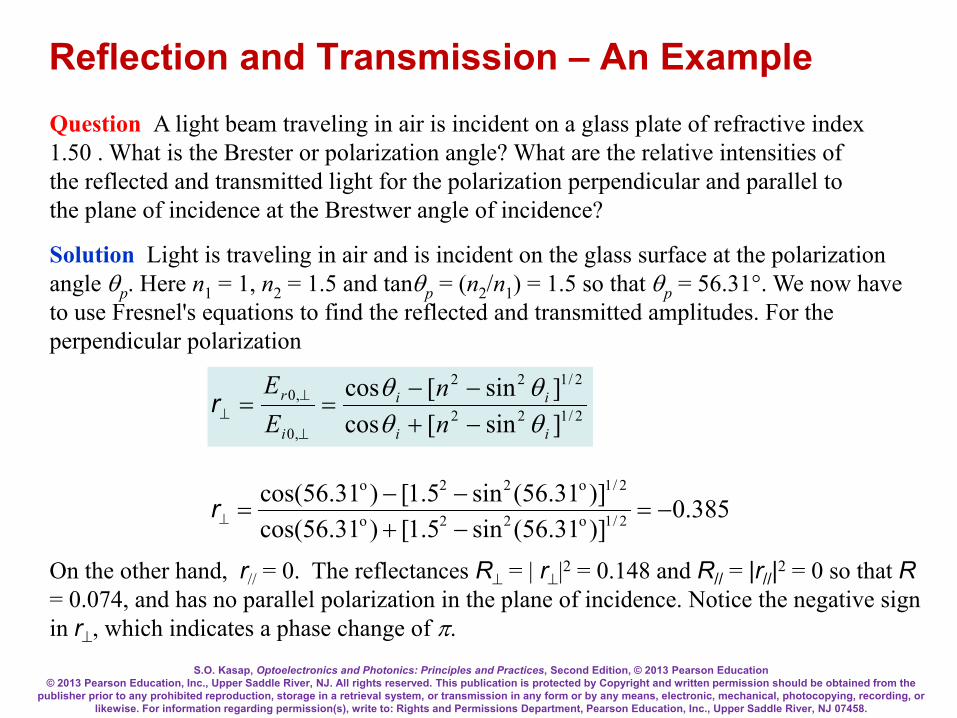
Reflection and Transmission – An Example Question A light beam traveling in air is incident on a glass plate of refractive index 1.50 . What is the Brester or polarization angle? What are the relative intensities of the reflected and transmitted light for the polarization perpendicular and parallel to the plane of incidence at the Brestwer angle of incidence?
Solution Light is traveling in air and is incident on the glass surface at the polarization angle θp. Here n1 = 1, n2 = 1.5 and tanθp = (n2/n1) = 1.5 so that θp = 56.31°. We now have to use Fresnel's equations to find the reflected and transmitted amplitudes. For the perpendicular polarization
385.0)]31.56(sin5.1[)31.56cos()]31.56(sin5.1[)31.56cos(
2/1o22o
2/1o22o
−=−+−−
=⊥r
On the other hand, r// = 0. The reflectances R⊥ = | r⊥|2 = 0.148 and R// = |r//|2 = 0 so that R = 0.074, and has no parallel polarization in the plane of incidence. Notice the negative sign in r⊥, which indicates a phase change of π.
2/122
2/122
,0
,0
]sin[cos]sin[cos
ii
ii
i
r
nn
EE
θθθθ
−+−−
==⊥
⊥⊥r

S.O. Kasap, Optoelectronics and Photonics: Principles and Practices, Second Edition, © 2013 Pearson Education © 2013 Pearson Education, Inc., Upper Saddle River, NJ. All rights reserved. This publication is protected by Copyright and written permission should be obtained from the
publisher prior to any prohibited reproduction, storage in a retrieval system, or transmission in any form or by any means, electronic, mechanical, photocopying, recording, or likewise. For information regarding permission(s), write to: Rights and Permissions Department, Pearson Education, Inc., Upper Saddle River, NJ 07458.
Reflection and Transmission – An Example
615.0)]31.56(sin5.1[)31.56cos(
)31.56cos(22/1o22o
o
=−+
=⊥t
667.0)]31.56(sin5.1[)31.56cos()5.1(
)31.56cos()5.1(22/1o22o2
o
// =−+
=t
Notice that r// + nt// = 1 and r⊥ + 1 = t⊥, as we expect.
2/122,0
,0
]sin[coscos2
ii
i
i
t
nEE
θθθ
−+==
⊥
⊥⊥t
2/1222//,0
//,0// ]sin[cos
cos2
ii
i
i
t
nnn
EE
θθθ−+
==t

S.O. Kasap, Optoelectronics and Photonics: Principles and Practices, Second Edition, © 2013 Pearson Education © 2013 Pearson Education, Inc., Upper Saddle River, NJ. All rights reserved. This publication is protected by Copyright and written permission should be obtained from the
publisher prior to any prohibited reproduction, storage in a retrieval system, or transmission in any form or by any means, electronic, mechanical, photocopying, recording, or likewise. For information regarding permission(s), write to: Rights and Permissions Department, Pearson Education, Inc., Upper Saddle River, NJ 07458.
Reflection and Transmission – An Example
852.0)615.0()31.56cos()1()69.33cos()5.1( 2
o
o
=
=⊥T1)667.0(
)31.56cos()1()69.33cos()5.1( 2
o
o
// =
=T
Clearly, light with polarization parallel to the plane of incidence has greater intensity. The total transmittance T = (0.852+1)/2 = 0.926. Note that R + T = 0.074 + 0.926 = 1. If we were to reflect light from a glass plate, keeping the angle of incidence at 56.3°, then the reflected light will be polarized with an electric field component perpendicular to the plane of incidence. The transmitted light will have the field greater in the plane of incidence, that is, it will be partially polarized. By using a stack of glass plates one can increase the polarization of the transmitted light. (This type of pile-of-plates polarizer was invented by Dominique F.J. Arago in 1812.)
To find the transmittance for each polarization, we need the refraction angle θt. From Snell's law, n1sinθi = ntsinθt i.e. (1)sin(56.31°) = (1.5)sinθt, we find θt = 33.69°.
2
1
22
1
2
2⊥
⊥
⊥⊥
== tT
nn
En
En
io
to
,
,2
//1
22
//,1
2
//,2// tT
==
nn
En
En
io
to
S.O. Kasap, Optoelectronics and Photonics: Principles and Practices, Second Edition, © 2013 Pearson Education © 2013 Pearson Education, Inc., Upper Saddle River, NJ. All rights reserved. This publication is protected by Copyright and written permission should be obtained from the
publisher prior to any prohibited reproduction, storage in a retrieval system, or transmission in any form or by any means, electronic, mechanical, photocopying, recording, or likewise. For information regarding permission(s), write to: Rights and Permissions Department, Pearson Education, Inc., Upper Saddle River, NJ 07458.
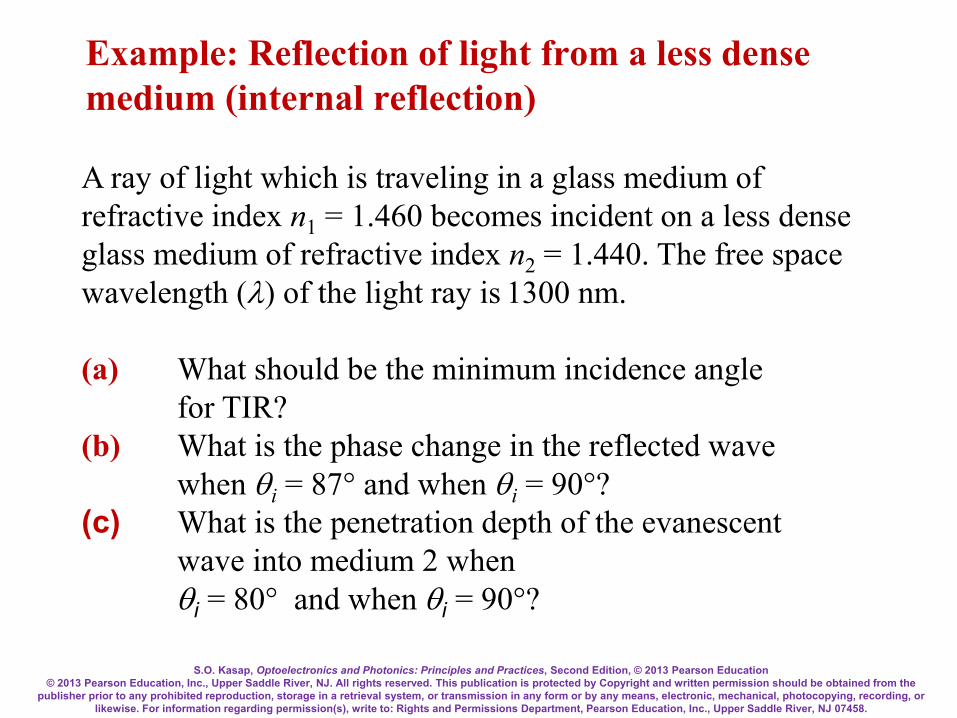
Example: Reflection of light from a less dense medium (internal reflection)
A ray of light which is traveling in a glass medium of refractive index n1 = 1.460 becomes incident on a less dense glass medium of refractive index n2 = 1.440. The free space wavelength (λ) of the light ray is 1300 nm. (a) What should be the minimum incidence angle for TIR? (b) What is the phase change in the reflected wave when θi = 87° and when θi = 90°? (c) What is the penetration depth of the evanescent wave into medium 2 when θi = 80° and when θi = 90°?
S.O. Kasap, Optoelectronics and Photonics: Principles and Practices, Second Edition, © 2013 Pearson Education © 2013 Pearson Education, Inc., Upper Saddle River, NJ. All rights reserved. This publication is protected by Copyright and written permission should be obtained from the
publisher prior to any prohibited reproduction, storage in a retrieval system, or transmission in any form or by any means, electronic, mechanical, photocopying, recording, or likewise. For information regarding permission(s), write to: Rights and Permissions Department, Pearson Education, Inc., Upper Saddle River, NJ 07458.
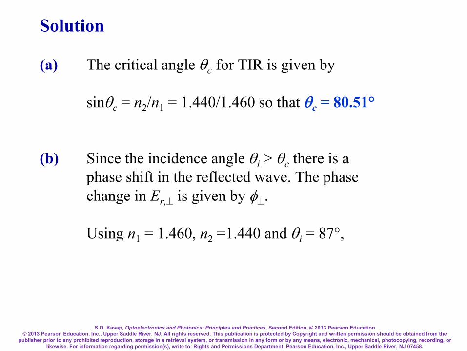
Solution (a) The critical angle θc for TIR is given by sinθc = n2/n1 = 1.440/1.460 so that θc = 80.51° (b) Since the incidence angle θi > θc there is a phase shift in the reflected wave. The phase change in Er,⊥ is given by φ⊥. Using n1 = 1.460, n2 =1.440 and θi = 87°,

S.O. Kasap, Optoelectronics and Photonics: Principles and Practices, Second Edition, © 2013 Pearson Education © 2013 Pearson Education, Inc., Upper Saddle River, NJ. All rights reserved. This publication is protected by Copyright and written permission should be obtained from the
publisher prior to any prohibited reproduction, storage in a retrieval system, or transmission in any form or by any means, electronic, mechanical, photocopying, recording, or likewise. For information regarding permission(s), write to: Rights and Permissions Department, Pearson Education, Inc., Upper Saddle River, NJ 07458.
= 2.989 = tan[1/2(143.0°)]
( ) [ ])87cos(460.1440.1)87(sin
cossintan
2/122
2/122
21
−
=−
=⊥i
i nθ
θφ
so that the phase change φ⊥ = 143°. For the Er,// component, the phase change is
( ) [ ] ( )⊥=−
=π+ φθ
θφ 21
22
2/122
21
//21 tan1
cossintan
nnn
i
i

S.O. Kasap, Optoelectronics and Photonics: Principles and Practices, Second Edition, © 2013 Pearson Education © 2013 Pearson Education, Inc., Upper Saddle River, NJ. All rights reserved. This publication is protected by Copyright and written permission should be obtained from the
publisher prior to any prohibited reproduction, storage in a retrieval system, or transmission in any form or by any means, electronic, mechanical, photocopying, recording, or likewise. For information regarding permission(s), write to: Rights and Permissions Department, Pearson Education, Inc., Upper Saddle River, NJ 07458.
so that tan(1/2φ// + 1/2π) = (n1/n2)2tan(φ⊥/2) = (1.460/1.440)2tan(1/2143°) which gives φ// = 143.95° − 180° or −36.05° Repeat with θi = 90° to find φ⊥ = 180° and φ// = 0°. Note that as long as θi > θc, the magnitude of the reflection coefficients are unity. Only the phase changes.
S.O. Kasap, Optoelectronics and Photonics: Principles and Practices, Second Edition, © 2013 Pearson Education © 2013 Pearson Education, Inc., Upper Saddle River, NJ. All rights reserved. This publication is protected by Copyright and written permission should be obtained from the
publisher prior to any prohibited reproduction, storage in a retrieval system, or transmission in any form or by any means, electronic, mechanical, photocopying, recording, or likewise. For information regarding permission(s), write to: Rights and Permissions Department, Pearson Education, Inc., Upper Saddle River, NJ 07458.
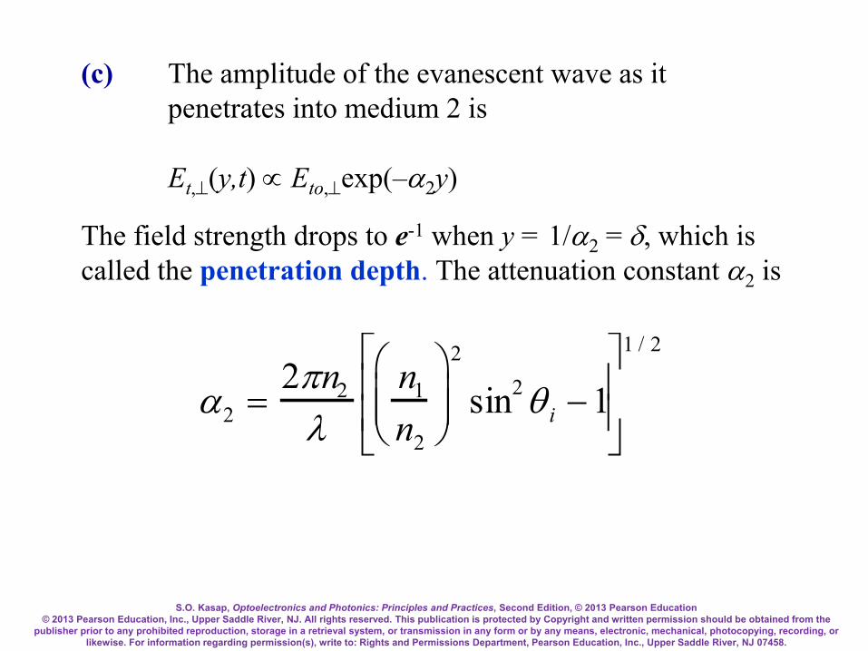
(c) The amplitude of the evanescent wave as it penetrates into medium 2 is Et,⊥(y,t) ∝ Eto,⊥exp(–α2y)
The field strength drops to e-1 when y = 1/α2 = δ, which is called the penetration depth. The attenuation constant α2 is
α2 =2πn2
λn1
n2
2
sin2 θ i −1
1 / 2
S.O. Kasap, Optoelectronics and Photonics: Principles and Practices, Second Edition, © 2013 Pearson Education © 2013 Pearson Education, Inc., Upper Saddle River, NJ. All rights reserved. This publication is protected by Copyright and written permission should be obtained from the
publisher prior to any prohibited reproduction, storage in a retrieval system, or transmission in any form or by any means, electronic, mechanical, photocopying, recording, or likewise. For information regarding permission(s), write to: Rights and Permissions Department, Pearson Education, Inc., Upper Saddle River, NJ 07458.
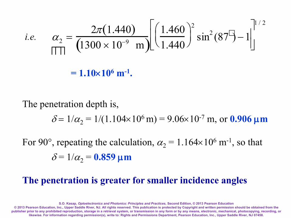
i.e.
α2 =2π 1.440( )
1300 ×10−9 m( )1.4601.440
2
sin2 (87) −1
1 / 2
= 1.10×10⁶ m-1.
The penetration depth is, δ = 1/α2 = 1/(1.104×106 m) = 9.06×10⁻⁷ m, or 0.906 µm For 90°, repeating the calculation, α2 = 1.164×10⁶ m-1, so that δ = 1/α2 = 0.859 µm The penetration is greater for smaller incidence angles

S.O. Kasap, Optoelectronics and Photonics: Principles and Practices, Second Edition, © 2013 Pearson Education © 2013 Pearson Education, Inc., Upper Saddle River, NJ. All rights reserved. This publication is protected by Copyright and written permission should be obtained from the
publisher prior to any prohibited reproduction, storage in a retrieval system, or transmission in any form or by any means, electronic, mechanical, photocopying, recording, or likewise. For information regarding permission(s), write to: Rights and Permissions Department, Pearson Education, Inc., Upper Saddle River, NJ 07458.
Example: Antireflection coatings on solar cells When light is incident on the surface of a semiconductor it becomes partially reflected. Partial reflection is an important energy loss in solar cells. The refractive index of Si is about 3.5 at wavelengths around 700 - 800 nm. Reflectance with n1(air) = 1 and n2(Si) ≈ 3.5 is
R =n1 − n2
n1 + n2
2
=1 − 3.51 + 3.5
2
= 0.309

S.O. Kasap, Optoelectronics and Photonics: Principles and Practices, Second Edition, © 2013 Pearson Education © 2013 Pearson Education, Inc., Upper Saddle River, NJ. All rights reserved. This publication is protected by Copyright and written permission should be obtained from the
publisher prior to any prohibited reproduction, storage in a retrieval system, or transmission in any form or by any means, electronic, mechanical, photocopying, recording, or likewise. For information regarding permission(s), write to: Rights and Permissions Department, Pearson Education, Inc., Upper Saddle River, NJ 07458.
30% of the light is reflected and is not available for conversion to electrical energy; a considerable reduction in the efficiency of the solar cell.
Illustration of how an antireflection coating reduces the reflected light intensity.

S.O. Kasap, Optoelectronics and Photonics: Principles and Practices, Second Edition, © 2013 Pearson Education © 2013 Pearson Education, Inc., Upper Saddle River, NJ. All rights reserved. This publication is protected by Copyright and written permission should be obtained from the
publisher prior to any prohibited reproduction, storage in a retrieval system, or transmission in any form or by any means, electronic, mechanical, photocopying, recording, or likewise. For information regarding permission(s), write to: Rights and Permissions Department, Pearson Education, Inc., Upper Saddle River, NJ 07458.
Light is first incident on the air/coating surface. Some of it becomes reflected as A in the figure. Wave A has experienced a 180° phase change on reflection because this is an external reflection. The wave that enters and travels in the coating then becomes reflected at the coating/semiconductor surface.
We can coat the surface of the semiconductor device with a thin layer of a dielectric material, e.g. Si3N4 (silicon nitride) that has an intermediate refractive index.
n1(air) = 1, n2(coating) ≈ 1.9 and n3(Si) = 3.5

S.O. Kasap, Optoelectronics and Photonics: Principles and Practices, Second Edition, © 2013 Pearson Education © 2013 Pearson Education, Inc., Upper Saddle River, NJ. All rights reserved. This publication is protected by Copyright and written permission should be obtained from the
publisher prior to any prohibited reproduction, storage in a retrieval system, or transmission in any form or by any means, electronic, mechanical, photocopying, recording, or likewise. For information regarding permission(s), write to: Rights and Permissions Department, Pearson Education, Inc., Upper Saddle River, NJ 07458.
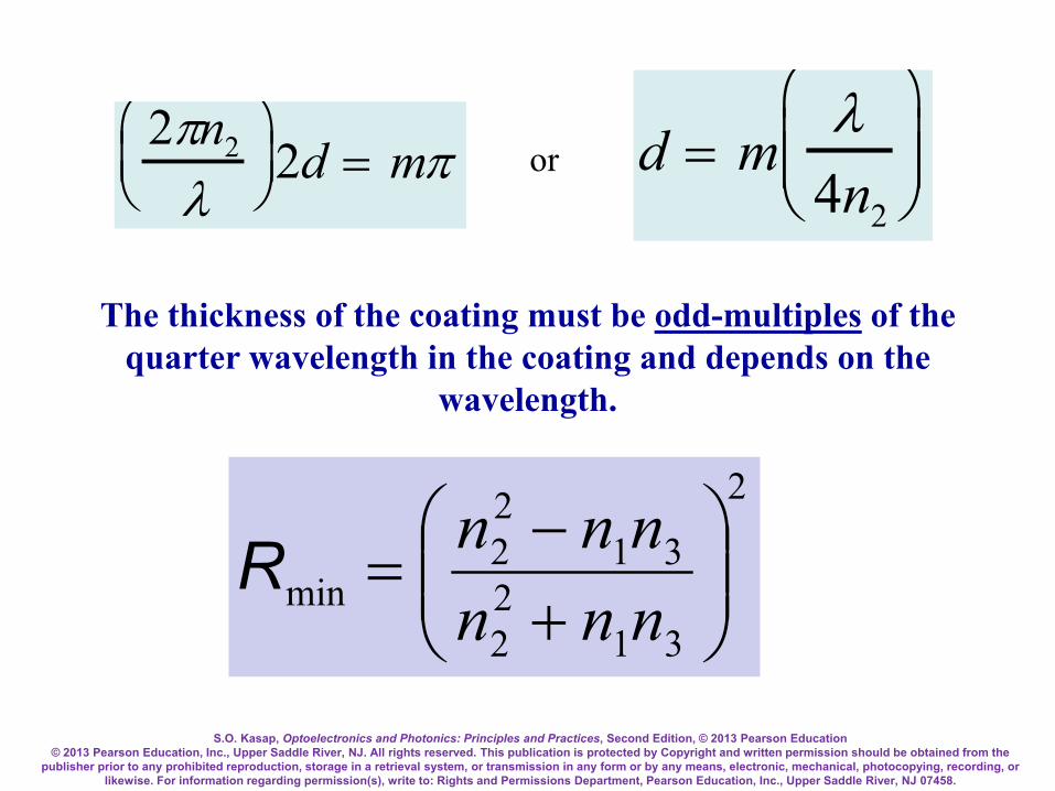
Since λc = λ /n2, where λ is the free-space wavelength, the phase difference ∆φ between A and B is (2πn2/λ)(2d). To reduce the reflected light, A and B must interfere destructively. This requires the phase difference to be π or odd-multiples of π, mπ where m = 1,3,5,… is an odd-integer. Thus
d
Antireflectioncoating
Surface
n1 n2 n3
AB
Semiconductor orphotovoltaic device
C
D
Incident lightThis reflected wave B, also suffers a 180° phase change since n3 > n2. When B reaches A, it has suffered a total delay of traversing the thickness d of the coating twice. The phase difference is equivalent to kc(2d) where kc = 2π/λc is the propagation constant in the coating, i.e. kc =2π/λc where λc is the wavelength in the coating.
S.O. Kasap, Optoelectronics and Photonics: Principles and Practices, Second Edition, © 2013 Pearson Education © 2013 Pearson Education, Inc., Upper Saddle River, NJ. All rights reserved. This publication is protected by Copyright and written permission should be obtained from the
publisher prior to any prohibited reproduction, storage in a retrieval system, or transmission in any form or by any means, electronic, mechanical, photocopying, recording, or likewise. For information regarding permission(s), write to: Rights and Permissions Department, Pearson Education, Inc., Upper Saddle River, NJ 07458.
or 2πn2
λ
2d = mπ d = m
λ4n2
The thickness of the coating must be odd-multiples of the quarter wavelength in the coating and depends on the
wavelength.
2
3122
3122
min
+−
=nnnnnnR

S.O. Kasap, Optoelectronics and Photonics: Principles and Practices, Second Edition, © 2013 Pearson Education © 2013 Pearson Education, Inc., Upper Saddle River, NJ. All rights reserved. This publication is protected by Copyright and written permission should be obtained from the
publisher prior to any prohibited reproduction, storage in a retrieval system, or transmission in any form or by any means, electronic, mechanical, photocopying, recording, or likewise. For information regarding permission(s), write to: Rights and Permissions Department, Pearson Education, Inc., Upper Saddle River, NJ 07458.
To obtain good destructive interference between waves A and B, the two amplitudes must be comparable. We need (proved later) n2 = √(n1n3). When n2 = √(n1n3) then the reflection coefficient between the air and coating is equal to that between the coating and the semiconductor. For a Si solar cell, √(3.5) or 1.87. Thus, Si3N4 is a good choice as an antireflection coating material on Si solar cells. Taking the wavelength to be 700 nm, d = (700 nm)/[4 (1.9)] = 92.1 nm or odd-multiples of d.
d = mλ
4n2

S.O. Kasap, Optoelectronics and Photonics: Principles and Practices, Second Edition, © 2013 Pearson Education © 2013 Pearson Education, Inc., Upper Saddle River, NJ. All rights reserved. This publication is protected by Copyright and written permission should be obtained from the
publisher prior to any prohibited reproduction, storage in a retrieval system, or transmission in any form or by any means, electronic, mechanical, photocopying, recording, or likewise. For information regarding permission(s), write to: Rights and Permissions Department, Pearson Education, Inc., Upper Saddle River, NJ 07458.
2
3122
3122
min
+−
=nnnnnnR
%24.000024.0)5.3)(1(9.1)5.3)(1(9.1
2
2
2
min or=
+−
=R
Reflection is almost entirely extinguished However, only at 700 nm.

S.O. Kasap, Optoelectronics and Photonics: Principles and Practices, Second Edition, © 2013 Pearson Education © 2013 Pearson Education, Inc., Upper Saddle River, NJ. All rights reserved. This publication is protected by Copyright and written permission should be obtained from the
publisher prior to any prohibited reproduction, storage in a retrieval system, or transmission in any form or by any means, electronic, mechanical, photocopying, recording, or likewise. For information regarding permission(s), write to: Rights and Permissions Department, Pearson Education, Inc., Upper Saddle River, NJ 07458.
Dielectric Mirror or Bragg Reflector
Schematic illustration of the principle of the dielectric mirror with many low and high refractive index layers and its reflectance.

S.O. Kasap, Optoelectronics and Photonics: Principles and Practices, Second Edition, © 2013 Pearson Education © 2013 Pearson Education, Inc., Upper Saddle River, NJ. All rights reserved. This publication is protected by Copyright and written permission should be obtained from the
publisher prior to any prohibited reproduction, storage in a retrieval system, or transmission in any form or by any means, electronic, mechanical, photocopying, recording, or likewise. For information regarding permission(s), write to: Rights and Permissions Department, Pearson Education, Inc., Upper Saddle River, NJ 07458.
Dielectric mirrors
Schematic illustration of the principle of the dielectric mirror with many low and high refractive index layers and its reflectance.
d1
n1 n2
AB
n1 n2
C
d2
D
d1 d2
z
LowHigh LowHighn0
n3
N = 1Substrate
N = 2
1 2 2 1 1 21 2

S.O. Kasap, Optoelectronics and Photonics: Principles and Practices, Second Edition, © 2013 Pearson Education © 2013 Pearson Education, Inc., Upper Saddle River, NJ. All rights reserved. This publication is protected by Copyright and written permission should be obtained from the
publisher prior to any prohibited reproduction, storage in a retrieval system, or transmission in any form or by any means, electronic, mechanical, photocopying, recording, or likewise. For information regarding permission(s), write to: Rights and Permissions Department, Pearson Education, Inc., Upper Saddle River, NJ 07458.
A dielectric mirror has a stack of dielectric layers of alternating refractive indices. Let n1 (= nH) > n2 (= nL) Layer thickness d = Quarter of wavelength or λlayer/4 λlayer = λo/n; λo is the free space wavelength at which the mirror is required to reflect the incident light, n = refractive index of layer. Reflected waves from the interfaces interfere constructively and give rise to a substantial reflected light. If there are sufficient number of layers, the reflectance can approach unity at λo.
d1
n1 n2
AB
n1 n2
C
d2
D
d1 d2
z
LowHigh LowHighn0
n3
N = 1Substrate
N = 2
1 2 2 1 1 21 2

S.O. Kasap, Optoelectronics and Photonics: Principles and Practices, Second Edition, © 2013 Pearson Education © 2013 Pearson Education, Inc., Upper Saddle River, NJ. All rights reserved. This publication is protected by Copyright and written permission should be obtained from the
publisher prior to any prohibited reproduction, storage in a retrieval system, or transmission in any form or by any means, electronic, mechanical, photocopying, recording, or likewise. For information regarding permission(s), write to: Rights and Permissions Department, Pearson Education, Inc., Upper Saddle River, NJ 07458.
r12 for light in layer 1 being reflected at the 1-2 boundary is r12 = (n1 − n2)/(n1 + n2) and is a positive number indicating no phase change. r21 for light in layer 2 being reflected at the 2-1 boundary is r21 = (n2 − n1)/(n2 + n1) which is –r12 (negative) indicating a π phase change. The reflection coefficient alternates in sign through the mirror The phase difference between A and B is 0 + π + 2k2d2 = 0 + π + 2(2πn2/λo)(λo/4n2) = 2π. Thus, waves A and B are in phase and interfere constructively. Dielectric mirrors are widely used in modern vertical cavity surface emitting semiconductor lasers.
d1
n1 n2
AB
n1 n2
C
d2
D
d1 d2
z
LowHigh LowHighn0
n3
N = 1Substrate
N = 2
1 2 2 1 1 21 2

S.O. Kasap, Optoelectronics and Photonics: Principles and Practices, Second Edition, © 2013 Pearson Education © 2013 Pearson Education, Inc., Upper Saddle River, NJ. All rights reserved. This publication is protected by Copyright and written permission should be obtained from the
publisher prior to any prohibited reproduction, storage in a retrieval system, or transmission in any form or by any means, electronic, mechanical, photocopying, recording, or likewise. For information regarding permission(s), write to: Rights and Permissions Department, Pearson Education, Inc., Upper Saddle River, NJ 07458.
Dielectric Mirror or Bragg Reflector
2
2230
21
2230
21
)/()/(
+−
= NN
NN
nnnnnnnn
NR
+−
≈∆
21
21arcsin)/4(nnnn
o
πλλ
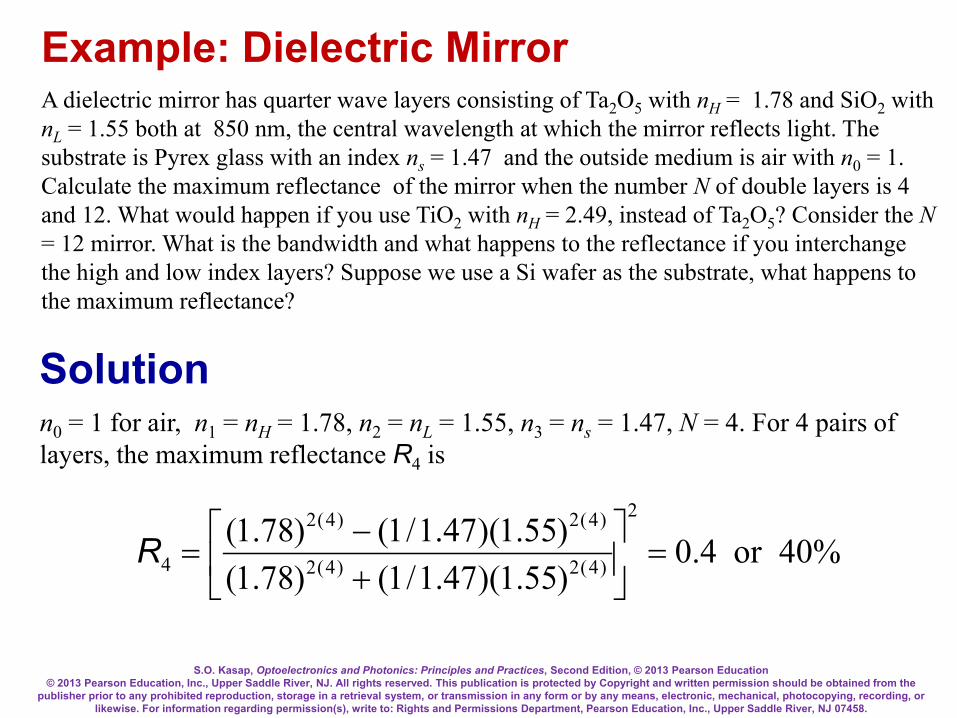
S.O. Kasap, Optoelectronics and Photonics: Principles and Practices, Second Edition, © 2013 Pearson Education © 2013 Pearson Education, Inc., Upper Saddle River, NJ. All rights reserved. This publication is protected by Copyright and written permission should be obtained from the
publisher prior to any prohibited reproduction, storage in a retrieval system, or transmission in any form or by any means, electronic, mechanical, photocopying, recording, or likewise. For information regarding permission(s), write to: Rights and Permissions Department, Pearson Education, Inc., Upper Saddle River, NJ 07458.
Example: Dielectric Mirror A dielectric mirror has quarter wave layers consisting of Ta2O5 with nH = 1.78 and SiO2 with nL = 1.55 both at 850 nm, the central wavelength at which the mirror reflects light. The substrate is Pyrex glass with an index ns = 1.47 and the outside medium is air with n0 = 1. Calculate the maximum reflectance of the mirror when the number N of double layers is 4 and 12. What would happen if you use TiO2 with nH = 2.49, instead of Ta2O5? Consider the N = 12 mirror. What is the bandwidth and what happens to the reflectance if you interchange the high and low index layers? Suppose we use a Si wafer as the substrate, what happens to the maximum reflectance?
Solution
%40or4.0)55.1)(47.1/1()78.1()55.1)(47.1/1()78.1(
2
)4(2)4(2
)4(2)4(2
4 =
+−
=R
n0 = 1 for air, n1 = nH = 1.78, n2 = nL = 1.55, n3 = ns = 1.47, N = 4. For 4 pairs of layers, the maximum reflectance R4 is

S.O. Kasap, Optoelectronics and Photonics: Principles and Practices, Second Edition, © 2013 Pearson Education © 2013 Pearson Education, Inc., Upper Saddle River, NJ. All rights reserved. This publication is protected by Copyright and written permission should be obtained from the
publisher prior to any prohibited reproduction, storage in a retrieval system, or transmission in any form or by any means, electronic, mechanical, photocopying, recording, or likewise. For information regarding permission(s), write to: Rights and Permissions Department, Pearson Education, Inc., Upper Saddle River, NJ 07458.
Solution
%6.90or906.0)55.1)(47.1/1()78.1()55.1)(47.1/1()78.1(
2
)12(2)12(2
)12(2)12(2
12 =
+−
=R
N = 12. For 12 pairs of layers, the maximum reflectance R12 is
Now use TiO2 for the high-n layer with n1 = nH = 2.49, R4 = 94.0% and R12 = 100% (to two decimal places).
The refractive index contrast is important. For the TiO2-SiO2 stack we only need 4 double layers to get roughly the same reflectance as from 12 pairs of layers of Ta2O5-SiO2. If we interchange nH and nL in the 12-pair stack, i.e. n1 = nL and n2 = nH, the Ta2O5-SiO2 reflectance falls to 80.8% but the TiO2-SiO2 stack is unaffected since it is already reflecting nearly all the light.

S.O. Kasap, Optoelectronics and Photonics: Principles and Practices, Second Edition, © 2013 Pearson Education © 2013 Pearson Education, Inc., Upper Saddle River, NJ. All rights reserved. This publication is protected by Copyright and written permission should be obtained from the
publisher prior to any prohibited reproduction, storage in a retrieval system, or transmission in any form or by any means, electronic, mechanical, photocopying, recording, or likewise. For information regarding permission(s), write to: Rights and Permissions Department, Pearson Education, Inc., Upper Saddle River, NJ 07458.
Solution We can only compare bandwidths ∆λ for "infinite" stacks (those with R ≈ 100%) For the TiO2-SiO2 stack
+−
≈∆12
12arcsin)/4(nnnn
o πλλ
For the Ta2O5-SiO2 infinite stack, we get ∆λ =74.8 nm
As expected ∆λ is narrower for the smaller contrast stack
nm25455.149.255.149.2arcsin)/4)(nm850( =
+−
≈∆ πλ

S.O. Kasap, Optoelectronics and Photonics: Principles and Practices, Second Edition, © 2013 Pearson Education © 2013 Pearson Education, Inc., Upper Saddle River, NJ. All rights reserved. This publication is protected by Copyright and written permission should be obtained from the
publisher prior to any prohibited reproduction, storage in a retrieval system, or transmission in any form or by any means, electronic, mechanical, photocopying, recording, or likewise. For information regarding permission(s), write to: Rights and Permissions Department, Pearson Education, Inc., Upper Saddle River, NJ 07458.
Complex Refractive Index
IdzdIα −=

S.O. Kasap, Optoelectronics and Photonics: Principles and Practices, Second Edition, © 2013 Pearson Education © 2013 Pearson Education, Inc., Upper Saddle River, NJ. All rights reserved. This publication is protected by Copyright and written permission should be obtained from the
publisher prior to any prohibited reproduction, storage in a retrieval system, or transmission in any form or by any means, electronic, mechanical, photocopying, recording, or likewise. For information regarding permission(s), write to: Rights and Permissions Department, Pearson Education, Inc., Upper Saddle River, NJ 07458.
Complex Refractive Index Consider k = k′ − jk″ E = Eoexp(−k″z)expj(ωt − k′z) I ∝|E|2 ∝ exp(−2k″z) We know from EM wave theory εr = εr′ − jεr″ and Ν = εr
1/2 Ν = n − jK = k/ko = (1/ko)[k′ − jk″]
rrr jjKn εεε ′′−′==−=Ν
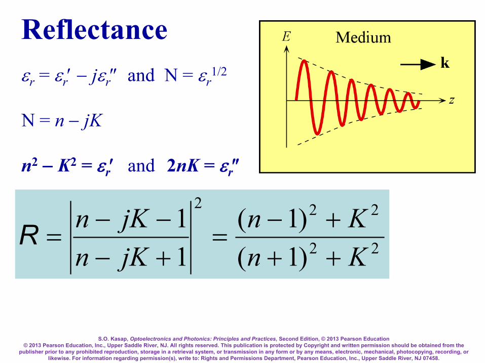
S.O. Kasap, Optoelectronics and Photonics: Principles and Practices, Second Edition, © 2013 Pearson Education © 2013 Pearson Education, Inc., Upper Saddle River, NJ. All rights reserved. This publication is protected by Copyright and written permission should be obtained from the
publisher prior to any prohibited reproduction, storage in a retrieval system, or transmission in any form or by any means, electronic, mechanical, photocopying, recording, or likewise. For information regarding permission(s), write to: Rights and Permissions Department, Pearson Education, Inc., Upper Saddle River, NJ 07458.
Reflectance εr = εr′ − jεr″ and Ν = εr
1/2 Ν = n − jK n2 − K2 = εr′ and 2nK = εr″
22
222
)1()1(
11
KnKn
jKnjKn
+++−
=+−−−
=R

S.O. Kasap, Optoelectronics and Photonics: Principles and Practices, Second Edition, © 2013 Pearson Education © 2013 Pearson Education, Inc., Upper Saddle River, NJ. All rights reserved. This publication is protected by Copyright and written permission should be obtained from the
publisher prior to any prohibited reproduction, storage in a retrieval system, or transmission in any form or by any means, electronic, mechanical, photocopying, recording, or likewise. For information regarding permission(s), write to: Rights and Permissions Department, Pearson Education, Inc., Upper Saddle River, NJ 07458.
Complex Refractive Index for CdTe
CdTe is used in various applications such as lenses, wedges, prisms, beam splitters, antireflection coatings, windows etc operating typically in the infrared region up to 25 µm. It is used as an optical material for low power CO2 laser applications.

S.O. Kasap, Optoelectronics and Photonics: Principles and Practices, Second Edition, © 2013 Pearson Education © 2013 Pearson Education, Inc., Upper Saddle River, NJ. All rights reserved. This publication is protected by Copyright and written permission should be obtained from the
publisher prior to any prohibited reproduction, storage in a retrieval system, or transmission in any form or by any means, electronic, mechanical, photocopying, recording, or likewise. For information regarding permission(s), write to: Rights and Permissions Department, Pearson Education, Inc., Upper Saddle River, NJ 07458.
Complex Refractive Index
n2 − K2 = εr′ and 2nK = εr″
rrr jjKn εεε ′′−′==−=Ν
22
222
)1()1(
11
KnKn
jKnjKn
+++−
=+−−−
=R
88 µm

S.O. Kasap, Optoelectronics and Photonics: Principles and Practices, Second Edition, © 2013 Pearson Education © 2013 Pearson Education, Inc., Upper Saddle River, NJ. All rights reserved. This publication is protected by Copyright and written permission should be obtained from the
publisher prior to any prohibited reproduction, storage in a retrieval system, or transmission in any form or by any means, electronic, mechanical, photocopying, recording, or likewise. For information regarding permission(s), write to: Rights and Permissions Department, Pearson Education, Inc., Upper Saddle River, NJ 07458.
Example: Complex Refractive Index for CdTe Calculate the absorption coefficient α and the reflectance R of CdTe at the Reststrahlen peak, and also at 50 µm. What is your conclusion?
Solution: At the Reststrahlen peak, λ ≈ 70 µm, K ≈ 6, and n ≈ 4. The free-space propagation constant is ko = 2π/λ = 2π/(70×10−6 m) = 9.0×10⁴ m−1 The absorption coefficient α is 2k, α = 2k″ = 2koK = 2(9.0×10⁴ m−1)(6) = 1.08×10⁶ m−1 which corresponds to an absorption depth 1/α of about 0.93 micron.

S.O. Kasap, Optoelectronics and Photonics: Principles and Practices, Second Edition, © 2013 Pearson Education © 2013 Pearson Education, Inc., Upper Saddle River, NJ. All rights reserved. This publication is protected by Copyright and written permission should be obtained from the
publisher prior to any prohibited reproduction, storage in a retrieval system, or transmission in any form or by any means, electronic, mechanical, photocopying, recording, or likewise. For information regarding permission(s), write to: Rights and Permissions Department, Pearson Education, Inc., Upper Saddle River, NJ 07458.
Solution continued: At the Reststrahlen peak, λ ≈ 70 µm, K ≈ 6, and n ≈ 4, so that
%74or74.06)14(6)14(
)1()1(
22
22
22
22
≈+++−
=+++−
=KnKnR
At λ = 50 µm, K ≈ 0.02, and n ≈ 2. Repeating the above calculations we get α = 5.0 ×10³ m−1
R = 0.11 or 11 % There is a sharp increase in the reflectance from 11 to 72% as we approach the Reststrahlen peak

S.O. Kasap, Optoelectronics and Photonics: Principles and Practices, Second Edition, © 2013 Pearson Education © 2013 Pearson Education, Inc., Upper Saddle River, NJ. All rights reserved. This publication is protected by Copyright and written permission should be obtained from the
publisher prior to any prohibited reproduction, storage in a retrieval system, or transmission in any form or by any means, electronic, mechanical, photocopying, recording, or likewise. For information regarding permission(s), write to: Rights and Permissions Department, Pearson Education, Inc., Upper Saddle River, NJ 07458.
Temporal and Spatial Coherence
(a) A sine wave is perfectly coherent and contains a well-defined frequency υo. (b) A finite wave train lasts for a duration ∆t and has a length l. Its frequency spectrum extends over ∆υ = 2/∆t. It has a coherence time ∆t and a coherence length λ. (c) White light exhibits practically no coherence.
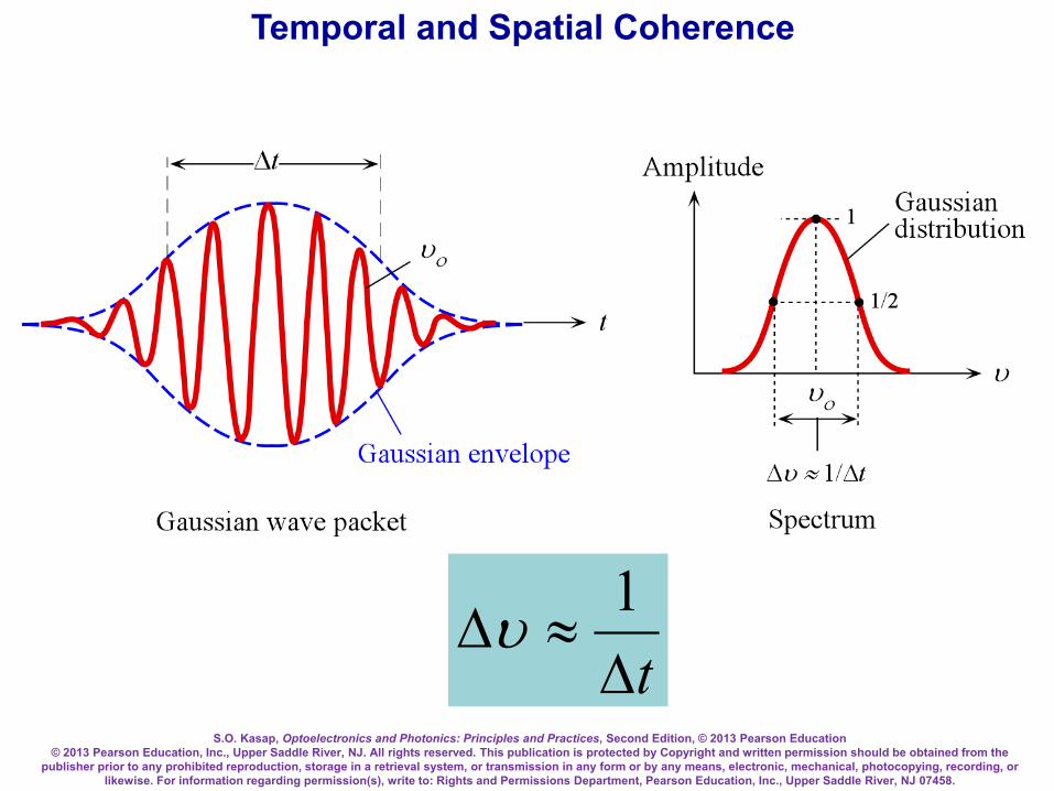
S.O. Kasap, Optoelectronics and Photonics: Principles and Practices, Second Edition, © 2013 Pearson Education © 2013 Pearson Education, Inc., Upper Saddle River, NJ. All rights reserved. This publication is protected by Copyright and written permission should be obtained from the
publisher prior to any prohibited reproduction, storage in a retrieval system, or transmission in any form or by any means, electronic, mechanical, photocopying, recording, or likewise. For information regarding permission(s), write to: Rights and Permissions Department, Pearson Education, Inc., Upper Saddle River, NJ 07458.
Temporal and Spatial Coherence
t∆≈∆
1υ

S.O. Kasap, Optoelectronics and Photonics: Principles and Practices, Second Edition, © 2013 Pearson Education © 2013 Pearson Education, Inc., Upper Saddle River, NJ. All rights reserved. This publication is protected by Copyright and written permission should be obtained from the
publisher prior to any prohibited reproduction, storage in a retrieval system, or transmission in any form or by any means, electronic, mechanical, photocopying, recording, or likewise. For information regarding permission(s), write to: Rights and Permissions Department, Pearson Education, Inc., Upper Saddle River, NJ 07458.
Temporal and Spatial Coherence
(a) Two waves can only interfere over the time interval ∆t. (b) Spatial coherence involves comparing the coherence of waves emitted from different locations on the source. (c) An incoherent beam
c
(a)
Time
(b)
A
B
∆ tInterference No interferenceNo interference
Space
c
P
Q
Source
Spatially coherent source
An incoherent beam(c)
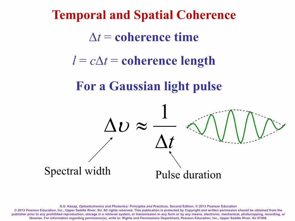
S.O. Kasap, Optoelectronics and Photonics: Principles and Practices, Second Edition, © 2013 Pearson Education © 2013 Pearson Education, Inc., Upper Saddle River, NJ. All rights reserved. This publication is protected by Copyright and written permission should be obtained from the
publisher prior to any prohibited reproduction, storage in a retrieval system, or transmission in any form or by any means, electronic, mechanical, photocopying, recording, or likewise. For information regarding permission(s), write to: Rights and Permissions Department, Pearson Education, Inc., Upper Saddle River, NJ 07458.
Temporal and Spatial Coherence
∆t = coherence time
l = c∆t = coherence length
For a Gaussian light pulse
Spectral width Pulse duration
t∆≈∆
1υ
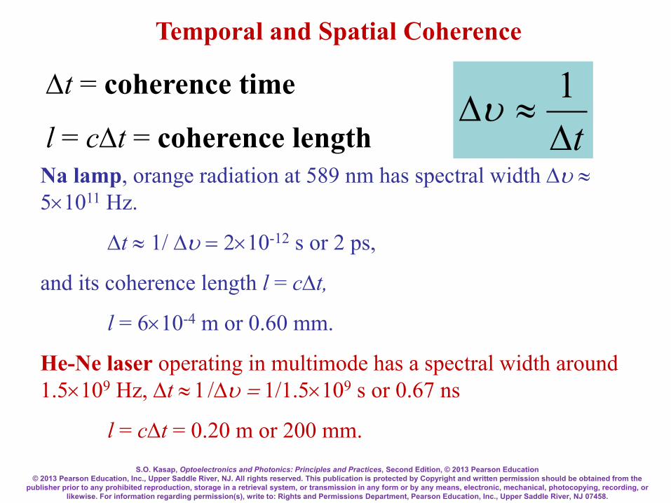
S.O. Kasap, Optoelectronics and Photonics: Principles and Practices, Second Edition, © 2013 Pearson Education © 2013 Pearson Education, Inc., Upper Saddle River, NJ. All rights reserved. This publication is protected by Copyright and written permission should be obtained from the
publisher prior to any prohibited reproduction, storage in a retrieval system, or transmission in any form or by any means, electronic, mechanical, photocopying, recording, or likewise. For information regarding permission(s), write to: Rights and Permissions Department, Pearson Education, Inc., Upper Saddle River, NJ 07458.
Temporal and Spatial Coherence
∆t = coherence time
l = c∆t = coherence length Na lamp, orange radiation at 589 nm has spectral width ∆υ ≈ 5×10¹¹ Hz.
∆t ≈ 1/ ∆υ = 2×10-12 s or 2 ps,
and its coherence length l = c∆t,
l = 6×10⁻⁴ m or 0.60 mm.
He-Ne laser operating in multimode has a spectral width around 1.5×10⁹ Hz, ∆t ≈ 1/∆υ = 1/1.5×109 s or 0.67 ns
l = c∆t = 0.20 m or 200 mm.
t∆≈∆
1υ

S.O. Kasap, Optoelectronics and Photonics: Principles and Practices, Second Edition, © 2013 Pearson Education © 2013 Pearson Education, Inc., Upper Saddle River, NJ. All rights reserved. This publication is protected by Copyright and written permission should be obtained from the
publisher prior to any prohibited reproduction, storage in a retrieval system, or transmission in any form or by any means, electronic, mechanical, photocopying, recording, or likewise. For information regarding permission(s), write to: Rights and Permissions Department, Pearson Education, Inc., Upper Saddle River, NJ 07458.
Diffraction
A light beam incident on a small circular aperture becomes diffracted and its light intensity pattern after passing through the aperture is a diffraction pattern with circular bright rings (called Airy rings). If the screen is far away from the aperture, this would be a Fraunhofer diffraction pattern. (Diffraction image obtained by SK)

S.O. Kasap, Optoelectronics and Photonics: Principles and Practices, Second Edition, © 2013 Pearson Education © 2013 Pearson Education, Inc., Upper Saddle River, NJ. All rights reserved. This publication is protected by Copyright and written permission should be obtained from the
publisher prior to any prohibited reproduction, storage in a retrieval system, or transmission in any form or by any means, electronic, mechanical, photocopying, recording, or likewise. For information regarding permission(s), write to: Rights and Permissions Department, Pearson Education, Inc., Upper Saddle River, NJ 07458.
A light beam incident on a small circular aperture becomes diffracted and its light intensity pattern after passing through the aperture is a diffraction pattern with circular bright rings (called Airy rings). If the screen is far away from the aperture, this would be a Fraunhofer diffraction pattern. (Image obtained by SK. Overexposed to highlight the outer rings)
Diffraction from a Circular Aperture

S.O. Kasap, Optoelectronics and Photonics: Principles and Practices, Second Edition, © 2013 Pearson Education © 2013 Pearson Education, Inc., Upper Saddle River, NJ. All rights reserved. This publication is protected by Copyright and written permission should be obtained from the
publisher prior to any prohibited reproduction, storage in a retrieval system, or transmission in any form or by any means, electronic, mechanical, photocopying, recording, or likewise. For information regarding permission(s), write to: Rights and Permissions Department, Pearson Education, Inc., Upper Saddle River, NJ 07458.
Diffraction Huygens-Fresnel principle Every unobstructed point of a wavefront, at a given instant in time, serves as a source of spherical secondary waves (with the same frequency as that of the primary wave). The amplitude of the optical field at any point beyond is the superposition of all these wavelets (considering their amplitudes and relative phases)

S.O. Kasap, Optoelectronics and Photonics: Principles and Practices, Second Edition, © 2013 Pearson Education © 2013 Pearson Education, Inc., Upper Saddle River, NJ. All rights reserved. This publication is protected by Copyright and written permission should be obtained from the
publisher prior to any prohibited reproduction, storage in a retrieval system, or transmission in any form or by any means, electronic, mechanical, photocopying, recording, or likewise. For information regarding permission(s), write to: Rights and Permissions Department, Pearson Education, Inc., Upper Saddle River, NJ 07458.
Diffraction
(a) Huygens-Fresnel principle states that each point in the aperture becomes a source of secondary waves (spherical waves). The spherical wavefronts are separated by λ. The new wavefront is the envelope of the all these spherical wavefronts. (b) Another possible wavefront occurs at an angle θ to the z-direction which is a diffracted wave.

S.O. Kasap, Optoelectronics and Photonics: Principles and Practices, Second Edition, © 2013 Pearson Education © 2013 Pearson Education, Inc., Upper Saddle River, NJ. All rights reserved. This publication is protected by Copyright and written permission should be obtained from the
publisher prior to any prohibited reproduction, storage in a retrieval system, or transmission in any form or by any means, electronic, mechanical, photocopying, recording, or likewise. For information regarding permission(s), write to: Rights and Permissions Department, Pearson Education, Inc., Upper Saddle River, NJ 07458.
(a) The aperture has a finite width a along y, but it is very long along x so that it is a one-dimensional slit. The aperture is divided into N number of point sources each occupying δy with amplitude proportional to δy since the slit is excited by a plane electromagnetic wave. (b) The intensity distribution in the received light at the screen far away from the aperture: the diffraction pattern. Note that the slit is very long along x and there is no diffraction along this dimension. (c) Diffraction patter obtained by using a laser beam from a pointer incident on a single slit.
Diffraction from a Single Slit

S.O. Kasap, Optoelectronics and Photonics: Principles and Practices, Second Edition, © 2013 Pearson Education © 2013 Pearson Education, Inc., Upper Saddle River, NJ. All rights reserved. This publication is protected by Copyright and written permission should be obtained from the
publisher prior to any prohibited reproduction, storage in a retrieval system, or transmission in any form or by any means, electronic, mechanical, photocopying, recording, or likewise. For information regarding permission(s), write to: Rights and Permissions Department, Pearson Education, Inc., Upper Saddle River, NJ 07458.
Diffraction from a Single Slit )sinexp()( θδδ jkyyE −∝
∫=
=
−=ay
y
jkyyCE0
)sinexp()( θδθ
θθ
θθ
sin)sinsin(
)(21
21sin
21
kakaaC
Ekaj−
=e
)(sinc)0(sin
)sinsin()( 2
2
21
21
βθ
θθ I
kakaaC
I =
′=
θβ sin21 ka=
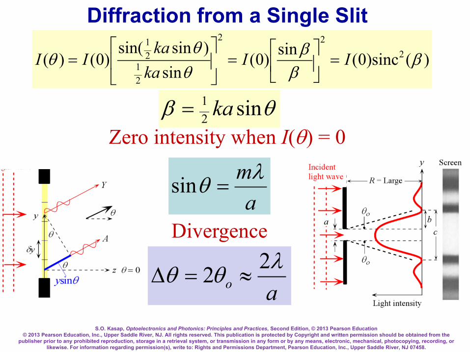
S.O. Kasap, Optoelectronics and Photonics: Principles and Practices, Second Edition, © 2013 Pearson Education © 2013 Pearson Education, Inc., Upper Saddle River, NJ. All rights reserved. This publication is protected by Copyright and written permission should be obtained from the
publisher prior to any prohibited reproduction, storage in a retrieval system, or transmission in any form or by any means, electronic, mechanical, photocopying, recording, or likewise. For information regarding permission(s), write to: Rights and Permissions Department, Pearson Education, Inc., Upper Saddle River, NJ 07458.
)(sinc)0(sin)0(sin
)sinsin()0()( 2
22
21
21
ββ
βθ
θθ II
kaka
II =
=
=
θβ sin21 ka=
Zero intensity when I(θ) = 0
amλθ =sin
Divergence
Diffraction from a Single Slit
aoλθθ 22 ≈=∆

S.O. Kasap, Optoelectronics and Photonics: Principles and Practices, Second Edition, © 2013 Pearson Education © 2013 Pearson Education, Inc., Upper Saddle River, NJ. All rights reserved. This publication is protected by Copyright and written permission should be obtained from the
publisher prior to any prohibited reproduction, storage in a retrieval system, or transmission in any form or by any means, electronic, mechanical, photocopying, recording, or likewise. For information regarding permission(s), write to: Rights and Permissions Department, Pearson Education, Inc., Upper Saddle River, NJ 07458.
Diffraction from a Circular Aperture
Doλθ 22.1sin = Diameter of
aperture
(Image obtained by SK)

S.O. Kasap, Optoelectronics and Photonics: Principles and Practices, Second Edition, © 2013 Pearson Education © 2013 Pearson Education, Inc., Upper Saddle River, NJ. All rights reserved. This publication is protected by Copyright and written permission should be obtained from the
publisher prior to any prohibited reproduction, storage in a retrieval system, or transmission in any form or by any means, electronic, mechanical, photocopying, recording, or likewise. For information regarding permission(s), write to: Rights and Permissions Department, Pearson Education, Inc., Upper Saddle River, NJ 07458.
a
b
The rectangular aperture of dimensions a × b on the left gives the diffraction pattern on the right. (b is twice a)
(Image obtained by SK. Overexposed to highlight the higher order lobes.)
Diffraction from a Rectangular Aperture

S.O. Kasap, Optoelectronics and Photonics: Principles and Practices, Second Edition, © 2013 Pearson Education © 2013 Pearson Education, Inc., Upper Saddle River, NJ. All rights reserved. This publication is protected by Copyright and written permission should be obtained from the
publisher prior to any prohibited reproduction, storage in a retrieval system, or transmission in any form or by any means, electronic, mechanical, photocopying, recording, or likewise. For information regarding permission(s), write to: Rights and Permissions Department, Pearson Education, Inc., Upper Saddle River, NJ 07458.
Diffraction pattern far away from a square aperture. The image has been overexposed to capture the faint side lobes (Image obtained by SK)
Diffraction from a Square Aperture

S.O. Kasap, Optoelectronics and Photonics: Principles and Practices, Second Edition, © 2013 Pearson Education © 2013 Pearson Education, Inc., Upper Saddle River, NJ. All rights reserved. This publication is protected by Copyright and written permission should be obtained from the
publisher prior to any prohibited reproduction, storage in a retrieval system, or transmission in any form or by any means, electronic, mechanical, photocopying, recording, or likewise. For information regarding permission(s), write to: Rights and Permissions Department, Pearson Education, Inc., Upper Saddle River, NJ 07458.
Diffraction pattern far away from a circular aperture. The image has been overexposed to capture the faint outer rings (By SK.)
Diffraction from a Circular Aperture

S.O. Kasap, Optoelectronics and Photonics: Principles and Practices, Second Edition, © 2013 Pearson Education © 2013 Pearson Education, Inc., Upper Saddle River, NJ. All rights reserved. This publication is protected by Copyright and written permission should be obtained from the
publisher prior to any prohibited reproduction, storage in a retrieval system, or transmission in any form or by any means, electronic, mechanical, photocopying, recording, or likewise. For information regarding permission(s), write to: Rights and Permissions Department, Pearson Education, Inc., Upper Saddle River, NJ 07458.
Diffraction from a Circular Aperture
George Bidell Airy (1801–1892, England). George Airy was a professor of astronomy
at Cambridge and then the Astronomer Royal at the Royal Observatory in
Greenwich, England. (© Mary Evans Picture Library/Alamy.)
21 )(2)(
=
γγγ JII o
γ = (1/2)kDsinθ
k = 2π/λ
ααγαπ
γπ
dJ )sincos(1)(01 −= ∫
Bessel function (first kind, first order)
Intensity distribution
(By SK)

S.O. Kasap, Optoelectronics and Photonics: Principles and Practices, Second Edition, © 2013 Pearson Education © 2013 Pearson Education, Inc., Upper Saddle River, NJ. All rights reserved. This publication is protected by Copyright and written permission should be obtained from the
publisher prior to any prohibited reproduction, storage in a retrieval system, or transmission in any form or by any means, electronic, mechanical, photocopying, recording, or likewise. For information regarding permission(s), write to: Rights and Permissions Department, Pearson Education, Inc., Upper Saddle River, NJ 07458.
Rayleigh Criterion
Resolution of imaging systems is limited by diffraction effects. As points S1 and S2 get closer, eventually the Airy patterns overlap so much that the resolution is lost. The Rayleigh criterion allows the minimum angular separation two of the point sources be determined. (Schematic illustration inasmuch as the side lobes are actually much smaller the center peak.)
Dλθ 22.1)sin( min =∆

S.O. Kasap, Optoelectronics and Photonics: Principles and Practices, Second Edition, © 2013 Pearson Education © 2013 Pearson Education, Inc., Upper Saddle River, NJ. All rights reserved. This publication is protected by Copyright and written permission should be obtained from the
publisher prior to any prohibited reproduction, storage in a retrieval system, or transmission in any form or by any means, electronic, mechanical, photocopying, recording, or likewise. For information regarding permission(s), write to: Rights and Permissions Department, Pearson Education, Inc., Upper Saddle River, NJ 07458.
Rayleigh Criterion
Image of two point sources captured through a small circular aperture. (a) The two points are fully resolved since the diffraction patterns of the two sources are sufficiently separated. (b) The two images near the Rayleigh limit of resolution. (c) The first dark ring through the center of the bright Airy disk of the other pattern. (Approximate.) (Images by SK)

S.O. Kasap, Optoelectronics and Photonics: Principles and Practices, Second Edition, © 2013 Pearson Education © 2013 Pearson Education, Inc., Upper Saddle River, NJ. All rights reserved. This publication is protected by Copyright and written permission should be obtained from the
publisher prior to any prohibited reproduction, storage in a retrieval system, or transmission in any form or by any means, electronic, mechanical, photocopying, recording, or likewise. For information regarding permission(s), write to: Rights and Permissions Department, Pearson Education, Inc., Upper Saddle River, NJ 07458.
Resolution of the Human Eye
The human eye has a pupil diameter of about 2 mm. What would be the minimum angular separation of two points under a green light of 550 nm and their minimum separation if the two objects are 30 cm from the eye?
The image will be diffraction pattern in the eye, and is a result of waves in this medium. If the refractive index n ≈ 1.33 (water) in the eye, then
)m 102)(33.1()m 10550(22.122.1)sin( 3
9
min −
−
××
==∆nDλθ
∆θmin = 0.0145° Their minimum separation s would be s = 2Ltan(∆θmin/2) = 2(300 mm)tan(0.0145°/2) = 0.076 mm = 76 micron which is about the thickness of a human hair (or this page).
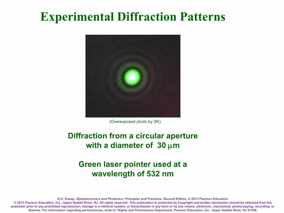
S.O. Kasap, Optoelectronics and Photonics: Principles and Practices, Second Edition, © 2013 Pearson Education © 2013 Pearson Education, Inc., Upper Saddle River, NJ. All rights reserved. This publication is protected by Copyright and written permission should be obtained from the
publisher prior to any prohibited reproduction, storage in a retrieval system, or transmission in any form or by any means, electronic, mechanical, photocopying, recording, or likewise. For information regarding permission(s), write to: Rights and Permissions Department, Pearson Education, Inc., Upper Saddle River, NJ 07458.
Diffraction from a circular aperture with a diameter of 30 µm
Green laser pointer used at a
wavelength of 532 nm
Experimental Diffraction Patterns
(Overexposed photo by SK)

S.O. Kasap, Optoelectronics and Photonics: Principles and Practices, Second Edition, © 2013 Pearson Education © 2013 Pearson Education, Inc., Upper Saddle River, NJ. All rights reserved. This publication is protected by Copyright and written permission should be obtained from the
publisher prior to any prohibited reproduction, storage in a retrieval system, or transmission in any form or by any means, electronic, mechanical, photocopying, recording, or likewise. For information regarding permission(s), write to: Rights and Permissions Department, Pearson Education, Inc., Upper Saddle River, NJ 07458.
Crossed slits 200 x 100 µm
Green laser pointer used at a wavelength of 532 nm
Experimental Diffraction Patterns
(Overexposed photo by SK)

S.O. Kasap, Optoelectronics and Photonics: Principles and Practices, Second Edition, © 2013 Pearson Education © 2013 Pearson Education, Inc., Upper Saddle River, NJ. All rights reserved. This publication is protected by Copyright and written permission should be obtained from the
publisher prior to any prohibited reproduction, storage in a retrieval system, or transmission in any form or by any means, electronic, mechanical, photocopying, recording, or likewise. For information regarding permission(s), write to: Rights and Permissions Department, Pearson Education, Inc., Upper Saddle River, NJ 07458.
Experimental Diffraction Patterns
Single slit with a width a
Green laser pointer used at a wavelength of 532 nm
a = 20 µm
a = 40 µm
a = 80 µm
a = 160 µm
(Overexposed photo by SK)

S.O. Kasap, Optoelectronics and Photonics: Principles and Practices, Second Edition, © 2013 Pearson Education © 2013 Pearson Education, Inc., Upper Saddle River, NJ. All rights reserved. This publication is protected by Copyright and written permission should be obtained from the
publisher prior to any prohibited reproduction, storage in a retrieval system, or transmission in any form or by any means, electronic, mechanical, photocopying, recording, or likewise. For information regarding permission(s), write to: Rights and Permissions Department, Pearson Education, Inc., Upper Saddle River, NJ 07458.
Single slit with a width 100 µm Blue = 402 nm
Green = 532 nm Red = 670 nm
Why does the central bright lobe get larger with increasing
wavelength?
Overexposed photo by SK
Experimental Diffraction Patterns
aoλθθ 22 ≈=∆
Answer

![UNIVERSITI MALAYSIA PERLISportal.unimap.edu.my/portal/page/portal30/STD_ACA_BULL_BOARD/ABB... · Asas Elektrik dan Elektronik [Basic Electrical and Electronic] PDT255 Kawalan Proses](https://img.dokumen.tips/doc/110x75/5e22eebce03c6c27371472ea/universiti-malaysia-asas-elektrik-dan-elektronik-basic-electrical-and-electronic.jpg)
![UNIVERSITI MALAYSIA PERLISportal.unimap.edu.my/portal/page/portal30/STD_ACA_BULL...Teori Litar Elektrik [Electric Circuit Theory] 9.00 pagi (am) 3 jam (hours) DKD 4 EKT112 Prinsip-prinsip](https://img.dokumen.tips/doc/110x75/60d5df26c10ff54a770fff61/universiti-malaysia-teori-litar-elektrik-electric-circuit-theory-900-pagi.jpg)


![UNIVERSITI MALAYSIA PERLISportal.unimap.edu.my/portal/page/portal30/STD_ACA... · ERT108 Kimia Fizikal [Physical Chemistry] PDT222 Metalurgi [Metallurgy] PDT346 Pengurusan Produk](https://img.dokumen.tips/doc/110x75/6098cbb99400df41a3745961/universiti-malaysia-ert108-kimia-fizikal-physical-chemistry-pdt222-metalurgi-metallurgy.jpg)