Embed Size (px)
Citation preview

AAiT, School of Civil and Environmental Engineering Reinforced Concrete II
Chapter 1: Inelastic Analysis and Moment Redistribution Page 1
CHAPTER 1. INELASTIC ANALYSIS OF CONTINUOUS BEAMS &
MOMENT REDISTRIBUTION
1.1. INTRODUCTION
Reinforced concrete structures are generally analyzed by the conventional elastic theory. In
flexural members, this is tantamount to assuming a linear moment-curvature relationship, even
under factored loads. For under-reinforced sections, this assumption is approximately true,
provided the reinforcing steel has not yielded at any section. Once yielding takes place(at any
section), the behavior of a statically indeterminate structure enters an inelastic phase, and linear
elastic structural analysis is strictly no longer valid.
For a proper determination of the distribution of bending moments for loading beyond the yielding
stage at any section, inelastic analysis is called for. This is generally referred to as limit analysis,
when applied to reinforced concrete framed structures, and ‘plastic analysis’ when applied to steel
structures. In the special case of reinforced concrete slabs, the inelastic analysis usually employed
is the ‘yield line analyses. The assumption generally made in limit analysis is that the moment-
curvature relation is an idealized bilinear elasto-plastic relation [Figure 1-1]. This has validity
only if the section is adequately under-reinforced and the reinforcing steel has a well-defined yield
plateau. The ultimate moment of resistance ( uRM ) of such sections, with specified area of steel,
can be easily assessed.

AAiT, School of Civil and Environmental Engineering Reinforced Concrete II
Chapter 1: Inelastic Analysis and Moment Redistribution Page 2
Figure 1-1: Idealized moment-curvature relation
1.2. METHODS OF ANALYSIS ALLOWED IN EBCS EN 2004:2014 (EUROCODE 2)
The methods of analysis provided in EC-2 are for the purpose to establish the distribution of either
internal forces and moments, or stresses, strains and displacements, over the whole or part of a
structure.
1. Linear Elastic Analysis
Based on the theory of elasticity
Suitable for both SLS and ULS
Assumptions:
i. Uncracked cross sections
ii. Linear stress-strain relationships and,
iii. Mean values of the elastic modulus [E]
For thermal deformation, settlement and shrinkage effects at the (ULS), a reduced stiffness
corresponding to the cracked sections may be assumed.
For the (SLS) gradual evolution of cracking should be considered (e.g. rigorous deflection
calculation).
2. Linear Elastic Analysis with Limited Redistribution

AAiT, School of Civil and Environmental Engineering Reinforced Concrete II
Chapter 1: Inelastic Analysis and Moment Redistribution Page 3
Although concrete structures only behave elastically under small loads while the sections remain
uncracked, a linear elastic analysis may still be used for both the serviceability and strength limit
states to determine the internal forces and moments, provided the structure has sufficient ductility
to distribute moments from highly stressed regions to less highly stressed regions.
At ultimate limit state plastic rotations occur at the most stressed sections. These rotations transfer
to other zones the effect of further load increase, thus allowing to take, for the design of
reinforcement, a reduced bending moment M , smaller than the moment M resulting from elastic
linear design, provided that in the other parts of the structure the corresponding variations of load
effects (viz. shear), necessary to ensure equilibrium, are considered.
Suitable for ULS
The moments at ULS calculated using a linear elastic analysis may be redistributed,
provided that the resulting distribution of moments remains in equilibrium with the
applied loads.
In continuous beams or slabs which:
a) Are predominantly subject to flexure and
b) Have the ratio of the lengths of adjacent spans in the range of 0.5 to 2,
redistribution of bending moments may be carried out without explicit check on the rotation
capacity, provided that:
1 2 uk k X d for 50ckf MPa
3 4 uk k X d for 50ckf MPa
5k for reinforcement class B & C
6k for reinforcement class A
Where
Is the ratio of the redistributed moment to the elastic bending moment
ux
Is the depth of the neutral axis at the ultimate limit state after redistribution
d Is the effective depth of the section
1cu
Is the ultimate strain for the section in accordance with Table 3.1
recommended value for k1 is 0,44, for k2 is 1,25(0,6+0,0014/εcu2), for k3 = 0,54, for k4 =
1,25(0,6+0,0014/εcu2), for k5 = 0,7 and k6 = 0,8
AAiT, School of Civil and Environmental Engineering Reinforced Concrete II
Chapter 1: Inelastic Analysis and Moment Redistribution Page 4
For the design of columns the elastic moments from frame action should be used without any
redistribution.
3. Plastic Analysis
Suitable ULS
Suitable for SLS if compatibility is ensured
When a beam yields in bending, an increase in curvature does not produce an increase in
moment resistance. Analysis of beams and structures made of such flexural members is
called plastic Analysis.
This is generally referred to as limit analysis, when applied to reinforced concrete framed
structures, and plastic analysis when applied to steel structures
4. Nonlinear analysis
Non-linear analysis is a procedure for calculation of action effects, based on idealizations of
the non-linear behavior of materials [non-linear constitutive laws: for concrete and steel], of
the elements and of the structure (cracking, second order effects), suitable for the nature of the
structure and for the ultimate limit state under consideration.
may be used for both ULS and SLS, provided that equilibrium and compatibility are
satisfied and an adequate non-linear behavior for materials is assumed.
The non-linear analysis procedures are more complex and therefore very time
consuming.
The analysis maybe first or second order.
1.3. MOMENT CURVATURE RELATIONSHIP
Although it is not needed explicitly in ordinary design, the relation between moment applied to a
given beam section and the resulting curvature, through the full range of loading to failure, is
important in several contexts. It is basic to the study of member ductility, understanding the
development of plastic hinges, and accounting for the redistribution of elastic moments that occurs
in most reinforced concrete structures before collapse.
The flexural behavior of a reinforced concrete cross-section (a non-linear material) can best be
studied by using its moment-curvature relationship. If the moment-curvature relationship is

AAiT, School of Civil and Environmental Engineering Reinforced Concrete II
Chapter 1: Inelastic Analysis and Moment Redistribution Page 5
available, one can predict the strength and the stiffness, as well as the ductility characteristics of
the cross-section.
1.3.1. CURVATURE
1.3.2. ELASTIC ANALYSIS OF BEAM SECTIONS
1.3.2.1. SECTION UN-CRACKED
As long as the tensile stress in the concrete is smaller than the tensile strength of concrete (fctk) the
strain and stress is the same as in an elastic, homogeneous beam. The only difference is the
presence of another material, i.e. the steel reinforcement. As it can be shown, in the elastic range,
for any given value of strain, the stress in the steel is 'n' times that of the concrete, where n =Es/Ec
is the modular ratio. In calculation the actual steel and concrete cross-section could be replaced by
a fictitious section (transformed section) thought of as consisting of concrete only. In this section
the actual steel area is replaced with an equivalent concrete area (nAs) located at the level of the
steel. Once the transformed section has been obtained, the beam is analyzed like an elastic
homogeneous beam.

AAiT, School of Civil and Environmental Engineering Reinforced Concrete II
Chapter 1: Inelastic Analysis and Moment Redistribution Page 6
Figure 1-2 - Transformed Un-Cracked Section
1.3.2.2. SECTION CRACKED
When the tension stresses fct exceeds fctk, cracks form in the tension zone of the section. If the
concrete compressive stress is smaller than approximately 0.5fck and the steel has not reached the
yield strength, both materials continue to behave elastically.
At this stage, it is assumed that tension cracks have progressed all the way to the neutral axis and
that sections that are plane before bending remain plane in the bent member. This situation of the
section, strain and stress distribution is shown in the Figure 1-3 below.
Figure 1-3 - Transformed Cracked Section
1.3.3. DRAWING THE MOMENT CURVATURE DIAGRAM
With the stress-strain relationships for steel and concrete, represented in idealized form and the
usual assumptions regarding perfect bond and plane sections, it is possible to calculate the relation
between moment and curvature for a typical under reinforced concrete beam section as follows.
A3
Compressive reinforcemnt
A1
Tensile reinforcemnt
A2
A3
Compressive reinforcemnt
A1
Tensile reinforcemnt
A2
AAiT, School of Civil and Environmental Engineering Reinforced Concrete II
Chapter 1: Inelastic Analysis and Moment Redistribution Page 7
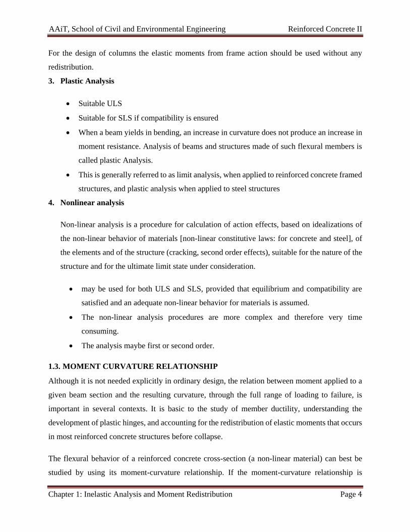
Figure 1-4 Moment-Curvature relationship for Reinforced Concrete Beam
A. Cracking point (point 1)
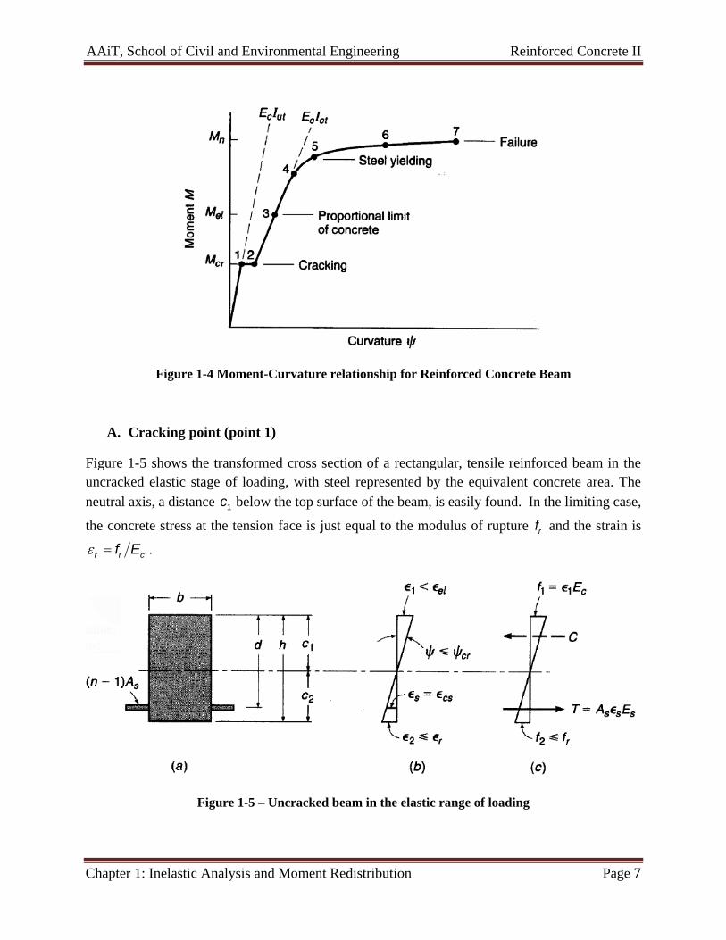
Figure 1-5 shows the transformed cross section of a rectangular, tensile reinforced beam in the
uncracked elastic stage of loading, with steel represented by the equivalent concrete area. The
neutral axis, a distance 1c below the top surface of the beam, is easily found. In the limiting case,
the concrete stress at the tension face is just equal to the modulus of rupture rf and the strain is
r r cf E .
Figure 1-5 – Uncracked beam in the elastic range of loading

AAiT, School of Civil and Environmental Engineering Reinforced Concrete II
Chapter 1: Inelastic Analysis and Moment Redistribution Page 8
The steel is well below yield at this stage, which can be confirmed by computing, from the strain
diagram, the steel strain. I is easily confirmed, also, that the maximum concrete compressive stress
will be well below the proportional limit. The curvature is
1
1 2
rcr
c c
(1)
And the corresponding moment is
2
r utcr
f IM
c
(2)
Where utI is the moment of inertia of the uncracked transformed section.
These values (ϕcr , Mcr) provide information needed to plot point “1” of Figure 1-4.
B. Elastic limit (point 3)
When the tensile cracking occurs at the section, the stiffness is immediately reduced, and curvature
increases to point “2” in Figure 1-4 with no increase in moment. The analysis now is based on the
cracked transformed section of Figure 1-6 with steel represented by the transformed concrete area
and tension concrete deleted. The cracked, elastic neutral axis distance 1c kd is easily found by
the usual methods.
Figure 1-6 – Cracked beam in the elstic range of material response
In the limiting case, the concrete strain just reaches the proportional limit as shown in Figure
1-6(b), and typically the steel is still below the yield strain. The curvature is easily computed by
1
1 1
elel
c c
(3)

AAiT, School of Civil and Environmental Engineering Reinforced Concrete II
Chapter 1: Inelastic Analysis and Moment Redistribution Page 9
And the corresponding moment can be calculated using moment is
21
2el elM f kjbd
(4)
This provides point 3 in Figure 1-4. The curvature at point 2 can now be found from the ratio
cr elM M .
C. Inelastic zone (point 3 – 7)
Next, the cracked, inelastic stage of loading is shown in Figure 1-7. Here the concrete is well into
the inelastic range, although the steel has not yielded. The neutral axis depth 1c is less than the
elastic kd and is changing with increasing load as the shape of the concrete stress distribution
changes and the steel stress changes.
Figure 1-7 – Cracked beam with concrete in the inelastic range of loading
It is now convenient to adopt the equations of c and c and equilibrium of force and moment to
find both the total concrete compressive force C and the location of its centroid, for any arbitrarily
selected value of maximum concrete strain 1 in this range. The entire process can be summarized
as follows:
1. Select any top face concrete strain 1 in the inelastic range, i.e., between el and u .
AAiT, School of Civil and Environmental Engineering Reinforced Concrete II
Chapter 1: Inelastic Analysis and Moment Redistribution Page 10
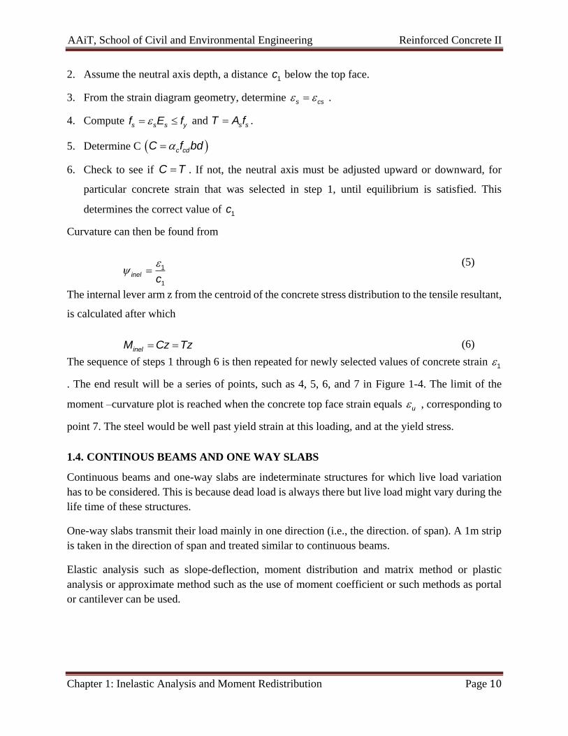
2. Assume the neutral axis depth, a distance 1c below the top face.
3. From the strain diagram geometry, determine s cs .
4. Compute s s s yf E f and s sT A f .
5. Determine C c cdC f bd
6. Check to see if C T . If not, the neutral axis must be adjusted upward or downward, for
particular concrete strain that was selected in step 1, until equilibrium is satisfied. This
determines the correct value of 1c
Curvature can then be found from
1
1
inelc
(5)
The internal lever arm z from the centroid of the concrete stress distribution to the tensile resultant,
is calculated after which
inelM Cz Tz (6)
The sequence of steps 1 through 6 is then repeated for newly selected values of concrete strain 1
. The end result will be a series of points, such as 4, 5, 6, and 7 in Figure 1-4. The limit of the
moment –curvature plot is reached when the concrete top face strain equals u , corresponding to
point 7. The steel would be well past yield strain at this loading, and at the yield stress.
1.4. CONTINOUS BEAMS AND ONE WAY SLABS
Continuous beams and one-way slabs are indeterminate structures for which live load variation
has to be considered. This is because dead load is always there but live load might vary during the
life time of these structures.
One-way slabs transmit their load mainly in one direction (i.e., the direction. of span). A 1m strip
is taken in the direction of span and treated similar to continuous beams.
Elastic analysis such as slope-deflection, moment distribution and matrix method or plastic
analysis or approximate method such as the use of moment coefficient or such methods as portal
or cantilever can be used.

AAiT, School of Civil and Environmental Engineering Reinforced Concrete II
Chapter 1: Inelastic Analysis and Moment Redistribution Page 11
1.4.1. LOAD ARRANGEMENT OF ACTIONS
The process of designing concrete structures involves identifying the relevant design situations
and limit states. These include persistent, transient or accidental situations. In each design situation
the structures should be verified at the relevant limit states.
In the analysis of the structure at the limit state being considered, the maximum effect of actions
should be obtained using a realistic arrangement of loads. Generally variable actions should be
arranged to produce the most unfavorable effect, for example to produce maximum overturning
moments in spans or maximum bending moments in supports.
For building structures, design concentrates mainly on the ULS, the ultimate limit state of strength
(STR), and SLS, the serviceability limit state. However, it is essential that all limit states are
considered. The limit states of equilibrium (EQU), strength at ULS with geotechnical actions
(STR/GEO) and accidental situations must be taken into account as appropriate.
1.4.1.1. Load Arrangement of Actions: In relation to Influence Lines
Figure 1-8 – One-way slab and continuous beam

AAiT, School of Civil and Environmental Engineering Reinforced Concrete II
Chapter 1: Inelastic Analysis and Moment Redistribution Page 12
The largest moment in continuous beams or one-way slabs or frames occur when some spans are
loaded and the others are not. Influence lines are used to determine which spans should be loaded
and which spans should not be to find the maximum load effect.
Figure 1-9a shows influence line for moment at B. The loading pattern that will give the largest
positive moment at consists of load on all spans having positive influence ordinates. Such loading
is shown in Figure 1-9b and is called alternate span loading or checkerboard loading.
The maximum negative moment at C results from loading all spans having negative influence
ordinate as shown in Figure 1-9d and is referred as an adjacent span loading.
Figure 1-9 Influence line for moment and loading patterns
Similarly, loading for maximum shear may be obtained by loading spans with positive shear
influence ordinate and are shown in Figure 1-10.

AAiT, School of Civil and Environmental Engineering Reinforced Concrete II
Chapter 1: Inelastic Analysis and Moment Redistribution Page 13
Figure 1-10 Influence line for shear
1.4.1.2. Load Arrangemnt of Actions: According Eurocode
In building structures, any of the following sets of simplified load arrangements may be used at
ULS and SLS. (EBCES EN 2004:2014 Section 5.1.2)
The more critical of:
a) Alternative spans carrying γGGk+ γQQk with other spans loaded with γGGk and
b) Any two adjacent spans carrying γGGk+ γQQk
Or the more critical of:
a) Alternative spans carrying γGGk+ γQQk with other spans loaded with γGGk and
b) Any two adjacent spans carrying γGGk+ γQQk
1.4.2. DESIGN OF CONTINUOUS BEAMS AND ONE WAY SLABS
After obtaining the maximum load effects, the design of continuous beams and one way slabs is
carried out as discussed in Reinforced Concrete Structures I course.
1.5. PLASTIC HINGES AND COLLAPSE MECHANISMS
If a short segment of a reinforced concrete beam is subjected to a bending moment, continued
plastic rotation is assumed to occur after the calculated ultimate moment Mu is reached, with no
change in applied moment. The beam behaves as if there were a hinge at that point. However, the
hinge will not be “friction free”, but will have a constant resistance to rotation.

AAiT, School of Civil and Environmental Engineering Reinforced Concrete II
Chapter 1: Inelastic Analysis and Moment Redistribution Page 14
If such a plastic hinge forms in a determinate structure, as shown in Figure 1-11, an uncontrolled
deflection takes place and the structure will collapse. The resulting system is referred to as a
mechanism. This implies that a statically determinate system requires the formation of only one
plastic hinge in order to become a mechanism.
Figure 1-11 – Determinate structure
If the structure is statically indeterminate, it is still stable after the formation of a plastic hinge, and
for further loading, it behaves as a modified structure with a hinge at the plastic hinge location
(and one less degree of indeterminacy). It can continue to carry additional loading (with formation
of additional plastic hinges) until the limit state of collapse is reached on account of one of the
following reasons:
formation of sufficient number of plastic hinges, to convert the structure (or a part of it)
into a ‘mechanism’;
Limitation in ductile behavior (i.e., curvature ϕ reaching the ultimate value ϕmax, or, in other
words a plastic hinge reaching its ultimate rotation capacity) at any one plastic hinge
location, resulting in local crushing of concrete at that section.
For illustration let us see the behavior of an indeterminate beam of Figure 1-12. It will be assumed
for simplicity that the beam is symmetrically reinforced, so that the negative bending capacity is
the same as the positive. Let the load P be increased gradually until the elastic moment at the fixed
support, 3PL/16 is just equal to the plastic moment capacity of the section, Mu. This load is

AAiT, School of Civil and Environmental Engineering Reinforced Concrete II
Chapter 1: Inelastic Analysis and Moment Redistribution Page 15
𝑃 = 𝑃𝑒𝑙 =16𝑀𝑢
3𝐿= 5.33
𝑀𝑢
3𝐿 (1.1)
At this load the positive moment under the load is 5
32 PL, as shown in Figure 1-12.
Figure 1-12 – Indeterminate Structures
The beam still responds elastically everywhere but at the left support. At that point the actual fixed
support can be replaced for purpose of analysis with a plastic hinge offering a known resisting
moment Mu, which makes the beam statically determinate.
The load can be increased further until the moment under the load also becomes equal to Mu, at
which load the second hinge forms. The structure is converted into a mechanism, as shown in
Figure 1-12(c), and collapse occurs. The moment diagram at collapse is shown in Figure 1-12(d).
The magnitude of the load causing collapse is easily calculated from the geometry of Figure
1-12(d).
𝑀𝑢 +𝑀𝑢
2=
𝑃𝐿
4
(7)
From which
𝑃 = 𝑃𝑢 =6𝑀𝑢
𝐿
(8)
By comparison, it is evident that an increase of 12.5% is possible beyond the load which caused
the formation of the first plastic hinge, before the beam will actually collapse. Due to the formation
of plastic hinges, a redistribution of moments has occurred such that, at failure, the ratio between
positive moment and negative moment is equal to that assumed in reinforcing the structure.

AAiT, School of Civil and Environmental Engineering Reinforced Concrete II
Chapter 1: Inelastic Analysis and Moment Redistribution Page 16
1.6. ROTATION CAPACITY
It may be evident that there is a direct relation between the amount of redistribution desired and
the amount of inelastic rotation at the critical sections of a beam required to produce the desired
redistribution. In general, the greater the modification of elastic-moment ratio, the greater the
required rotation capacity to accomplish that change. Thus the designer adopting the limit/plastic
analysis in concrete must calculate the inelastic rotation capacity it undergoes at plastic-hinge
locations.
One way to calculate this rotation capacity is making use of the moment-curvature relationship
established for a given section. But his plastic rotation is not confined to one cross section but is
distributed over a finite length referred to as the hinging length pl .
The total inelastic rotation s can be found by multiplying the average curvature by the hinging
length:
ults ult yd p
yd
Mk k l
M
(9)
where
ultk Curvature at the ultimate point of the moment curvature diagram
ydk Curvature at the yield point of the moment curvature diagram
ultM moment at the ultimate point of the moment curvature diagram
ydM moment at the yield point of the moment curvature diagram
pl 1.2h In which z is the distance from the point of maximum moment to the nearest point
of zero moment
Figure 1-13 – Plastic rotation of s of reinforced concrete sections for continuous beams and
continuous one way spanning slabs

AAiT, School of Civil and Environmental Engineering Reinforced Concrete II
Chapter 1: Inelastic Analysis and Moment Redistribution Page 17
According to section 5.6.3 of EBCS EN 2004:2014, verification of the plastic rotation in the
ultimate limit state is considered to be fulfilled, if it is shown that under the relevant action, the
calculated rotation, s , is less than or equal to the allowable plastic rotation, ,pl d
In the simplified procedure, the allowable plastic rotation may be determined by multiplying the
basic value of allowable rotation by a correction factor k that depends on the shear slenderness.
The recommended basic value of allowable rotation, for steel classes B and C (the use of Class A
steel is not recommended for plastic analysis) and concrete strength classes less than or equal to
C50/60 and C90/105 are given in Figure 1-14.
Figure 1-14 – Allowable plastic rotation, ,pl d , of reinforced concrete sections for Class B and C
reinforcement.
The values in Figure 1-14 apply for a shear slenderness 3.0 . For different values of shear
slenderness ,pl d should be multiplied by k .
3k (10)
Where:
is the ratio of the distance between point zero and maximum moment after redistribution and
effective depth, d. As a simplification may be calculated for the concordant design values of the
bending moment and shear. sd sdM V d
AAiT, School of Civil and Environmental Engineering Reinforced Concrete II
Chapter 1: Inelastic Analysis and Moment Redistribution Page 18
1.7. MOMENT REDISTRIBUTION
Statically indeterminate structures made of reinforced concrete like fixed ended one span beams,
continuous beams and frames are designed considering internal forces like bending moment, shear
force and axial thrust obtained from structural analysis. Either one or several sections of these
structures may have peak values of the internal forces, which are designated as critical sections.
These sections are dimensioned and reinforced accordingly. Flexural members, however, do not
collapse immediately as soon as the loads at a particular section cause bendding moment exceeding
the maximum resisting moment capacity of that section. Instead, that section starts rotating at
almost constant moment. This is known as formation of plastic hinge at that section reaching its
maximum resisting moment capacity. The section then transfers loads to other sections if the
applied loads are further increased. This process continues till the structures have plastic hinges at
sufficient sectins to form a failure mechanism when it actually collapses. However, significant
transfer of loads has occurred before the collapse of the structure. This transfer of loads after the
formation of first plastic hinge at section having the higest bending moment till the collapse of the
structure is known as redistribution of moments. By this process, therefore, the structure continues
to accommodate higher loads before it collapses.
The elastic bending moment diagram prior to the formation of first plastic hinge and the final
bending moment diagram just before the collapse are far different. The ratio of the negative to
positive elastic bending moments is no more valid. The development of plastic hinges depends on
the available plastic moment capacity at critical sections. It is worth mentioning that the
redistribution of moment is possible if the section forming the plastic hinge has the ability to rotate
at constant moment, which depends on the amount of reinforcement actually provided at that
section. The section must be under-reinforced and should have sufficient ductility.
This phenomenon is well known in steel structures. However, the redistribution of moment has
also been confirmed in reinforced concrete structure by experimental investigations. It is also a
fact that reinforced concrete structures have comparatively lower capacity to rotate than steel
structures. yet, this phenomenon is drawing the attention of the designers. Presently, design codes
of most of the countries allow the redistribution up to a maximum limit because of the following
advantages:
1) It gives a more realistic picture of the actual load carrying capacity of the indeterminate
structure.
2) Structures designed considering the redistribution of moment (though limited) would result
in economy as the actual load capacity is higher than that we determine from any elastic
analysis.
3) The designer enjoys the freedom of modifying the design bending moments within limits.
These adjustments are sometimes helpful in reducing the reinforcing bars, which are
crowded, especially at locations of high bending moment.

AAiT, School of Civil and Environmental Engineering Reinforced Concrete II
Chapter 1: Inelastic Analysis and Moment Redistribution Page 19
The choice of the bending moment diagram after the redistribution should satisfy the equilibrium
of internal forces and external loads. Moreover, it must ensure the following:
1. The plastic rotations required at the critical sections should not exceed the amount the
sections can sustain.
2. The extent of cracking or the amount of deformation should not make the performance
unsatisfactory under service loads.