Embed Size (px)
Citation preview

Table of Contents
- i -
draPRO Training Manual - Issue 2016.1
Contents
Chapter 1 Getting Started ........................................................................ 1
1.1 The Application Loader .......................................................... 2
1.2 AutoSYS 8.0 ............................................................................... 2
1.3 draPRO . .................................................................................... 3
Chapter 2 User Interface .......................................................................... 5
2.1 Introduction .............................................................................. 6
2.2 Modified AutoCAD Toolbars .................................................. 7
2.3 New draPRO Toolbars .............................................................. 8
Chapter 3 Drawing Creation Interface ...............................................11
3.1 Introduction ............................................................................ 12
3.2 Creating a New Drawing Using draPRO ............................ 12
3.3 Drawing Sheet Visibility ......................................................... 14
3.4 Adding Title Labels ................................................................ 15
3.5 Adding Revisions .................................................................... 15
3.6 Revision Cloulds & Triangles ................................................. 16
3.7 Adding to the Revision Table ............................................... 17
3.8 Opening an Existing Drawing ............................................... 18
3.9 Re-scaling an Existing Drawing ............................................ 19
Chapter 4 Layers with draPRO ...............................................................21
4.1 Introduction ............................................................................ 22
4.2 Creating Basic Layers- Selecting a Pen .............................. 23
4.3 To use a draPRO Base Layer ................................................. 24
4.4 Text - The AutoSYS Way ......................................................... 24
4.5 Creating Single Lined text ..................................................... 25
4.6 Creating Multiline or Paragraph Text .................................. 26

Table of Contents
- ii -
draPRO Training Manual - Issue 2016.1
4.7 Creating Enhanced Layers .................................................. 26
4.8 Default Enhanced Layer Structure ...................................... 27
4.9 Setting an Enhanced Layer .................................................. 28
4.10 Creating Enhanced Layers “On the fly” .............................. 30
4.11 Adding NEW Enhanced Layer Names ................................. 31
4.12 Setting a Layer Current by Selecting an Object .............. 31
4.13 Worked Example ................................................................... 32
Chapter 5 Application Loader ...............................................................35
5.1 Appliaction Loader Basics..................................................... 36
5.2 The Application Loader Toolbar ........................................... 36
5.3 Unloading an Application .................................................... 37
5.4 Setting an Application to Autoload .................................... 37
Chapter 6 draPRO ......................................................................................39
6.1 draPRO Base ........................................................................... 40
6.2 To Load a Building Services Module .................................... 41
6.3 draPRO Base Additional Flyouts .......................................... 42
6.4 Setting a draPRO Application to Autoload ....................... 42
6.5 Quick Keys ............................................................................... 43
Chapter 7 Model/Paper Format ...........................................................47
7.1 Working in Paper/Model Space .......................................... 48
7.2 Paper/Model ......................................................................... 48
7.3 Advantages ............................................................................ 49
7.4 Disadvantages ....................................................................... 49
7.5 Model Space Viewport Boundaries Explained .................. 49
7.6 Using Model Space Viewport Boundaries ........................... 50
7.7 Dimensioning in Bounding Boxes .......................................... 52
7.8 Rescale Bounding Boxes ....................................................... 52
7.9 Displaying Bounding Boxes Settings .................................... 53
7.10 Highlight current Viewport Bounding Box .......................... 53
7.11 Creating a Paper Space Viewport ..................................... 53

Table of Contents
- iii -
draPRO Training Manual - Issue 2016.1
Chapter 8 Getting around the draPRO features .............................55
8.1 Menu Bar ................................................................................. 56
8.2 Toolbars ................................................................................... 57
8.3 Dialog Boxes ........................................................................... 58
8.4 Online Help ............................................................................. 59

Chapter 1
- 1 -
draPRO Training Manual - Issue 2016.1
Getting Started
draPRO Introduction
draPRO is a quality management and drawing
productivity system for companies or contractors who
require.
� Toolbar quality systems management.
� The ability to run one or more third party
applications.
� Drawing to be produced for multiple clients .
� Many routines that enable designer & detailer to
produce ”Building Services” documenation.
This manual should be read in conjunction with the
AutoCAD Reference Manual. It is assumed that the user is
familiar with the use of standard AutoCAD commands
1
Course Information
1.1 The Application Loader
1.2 AutoSYS 8.0
1.3 draPRO

Chapter 1
- 2 -
draPRO Training Manual - Issue 2016.1
1.1 The Application Loader.
The Application Loader is a tool to help you manage the growing number of
AutoCAD applications. In other words, an application that manages other
applications. For example, if you had draPRO and Cadpipe then you would normally
run them through their own icon and separate AutoCAD sessions would be opened.
Through using the Application Loader you are able to run them in a single AutoCAD
session.
1.2 AutoSYS 8.0.
AutoSYS provides a flexible, customizable electronic and hard copy CAD structure.
That can be readily adapted to suit any company’s standards whether internal or
external along with other company standards as well as international.
AutoSYS is a product that improves AutoCAD useability and setup immensely. It sits as
a layer between AutoCAD and the user, managing the drawing structure and quality
systems.
A drawing quality system is the adoption of a standard code of practice in two
areas:
� Hard copy
� Electronic naming practices for layers, text and drawing sheets
When drawings were produced by hand, (that is before CAD) and we changed from
one project to another, there was no major change to the way drawings were
produced. As drawing, was simply a matter of using a pen to draw lines on paper.
The hardest part was selecting the correct pre-printed sheet.
With CAD (and the many and varied layer and tablet structures), changing from one
client or project to another usually means an entire concept change in the way you
interact with AutoCAD. As in most cases, every company using AutoCAD to produce
engineering drawings establishes a different system of layers and other electronic
standards.
The AutoSYS client profile system eliminates this concept change. Each client defined
in AutoSYS is allocated a unique 3 character client code. A set of client definition files
is associated with this code and these files are used to store the CAD standards
required for each client. These client definition files can be stored on a workstation or
network server.
When its time to go onto another project, the CAD standards defined for that project
can be quickly established within AutoSYS. The basic user interface does not
change, but once that client is selected (when creating a new drawing) all objects
will now be produced in accordance with the new clients' CAD standard. An
unlimited number of Clients can be built into AutoSYS and called back at any time.
Once a client definition has been created, it never has to be re-done.

Chapter 1
- 3 -
draPRO Training Manual - Issue 2016.1
This means you can have any number of workstations, producing different types of
drawings, using different applications all on a common interface to ANY established
CAD standard system, controlled either at an administrator or workstation level.
AutoSYS stores the list of clients and the associated client definition code in the
AutoSYS system file, AUTOSYS.INI. Where the AutoSYS system file and the client
definition files are stored depends on the type of installation you are running.
In a stand alone installation, both the system file and the client definition file are
located on the workstation.
In a network installation the system file will always be located either on the
workstation or in the user’s home directory. While all client definition files are stored on
a network server. This allows each user to have their own client list with the client
definitions being stored, accessed and managed from the network server.
Once you become familiar with the location of the Toolbars and the layout of the
desktop, operating AutoSYS and the Application Loader will be a breeze.
1.3 draPRO.
draPRO has many routines that enable the designer, detailer & general drafter to
produce “Building Services” documentation at a much more productive pace.
draPRO delivers the diverse fields of Building Services documentation, such as
draPRO – Mechanical Design, draPRO-Workshop, draPRO-Hydralic Services, draPRO-
Electrical Serices, or draPRO-Fire Services.
These product Routines Include:
� Layer Management.
� Standardised Blocks.
� Automated Routines for HVAC.
� Architectural Clean up.
� draLIB Equipment Library .
� General Enhanced Editing Tools.
� Scheduling.
� Batching Plotting and General Batching.

Chapter 1
- 4 -
draPRO Training Manual - Issue 2016.1
Chapter 2
- 5 -
draPRO Training Manual - Issue 2016.1
User Interface
Chapter Introduction
This chapter covers the following topics:
2.1 Introduction.
2.2 Modified AutoCAD Toolbars.
2.3 New draPRO Toolbars.
2
In this chapter
After completing this chapter,
you will be able to
� Identify Key terms for
draPRO
� Identify and use the user
interface components
� Locate and use the
modified toolbars and
flyouts
� Understand the modified
command line status
window.

Chapter 2
- 6 -
draPRO Training Manual – Issue 2016.1
2.1 Introduction.
The end result of using the draPRO interface is to increase the useability of AutoCAD
for both new and experienced AutoCAD users, in a controlled environment.
The user interface is based on the standard AutoCAD for Windows layout. To make
the transition between using AutoCAD and draPRO easier, we have added AutoSYS
functionality to the existing AutoCAD toolbar settings. Additional utilities have been
included in new toolbars and flyouts.
Command Status Line.
draPRO provides additional information relating to the current drawing in the
AutoCAD Status line, this includes:
• Base drawing scale or the current viewport bounding box scale
• The current setting for the dimension linear scale (DIMLFAC)
• The current setting for the MAIN and SECONDARY layer name

Chapter 2
- 7 -
draPRO Training Manual – Issue 2016.1
• The current setting for the AutoCAD Text Style.
• The current setting for the Number Pad Osnaps. (On/Off)
Sc
ale
Dim
Sc
ale
Ma
in L
ay
er
Se
co
nd
ary
La
ye
r
Fo
nt
Osn
ap
s O
n/O
ff

Chapter 2
- 8 -
draPRO Training Manual – Issue 2016.1
2.2 Modified AutoCAD Toolbars.
The existing main toolbars that have been modified are:
• Standard Toolbar
• Draw Toolbar
• Modify Toolbar
• Dimension Toolbars
These are defined in the AutoSYS Menu’s…..

Chapter 2
- 9 -
draPRO Training Manual – Issue 2016.1
2.3 New draPRO Toolbars.
The key new toolbars that have been added include:
• Application Loader.
• draPRO Applications.
• draPRO Base
• Mechanical Design.
• Mechanical Workshop.
• Workshop Melb Services.
• Electrical Services.

Chapter 2
- 10 -
draPRO Training Manual – Issue 2016.1
• Fire Services.
• Hydralic Services.
The draPRO toolbar menu’s are added so services and service routines can be
quickly loaded.

Chapter 2
- 11 -
draPRO Training Manual – Issue 2016.1
Chapter 3
- 11 -
draPRO Training Manual - Issue 2016.1
Drawing Creation
Interface
Chapter Introduction
This chapter covers the following topics:
3.1 Introduction.
3.2 Creating a New Drawing Using draPRO.
3.3 Drawing Sheet Visibility.
3.4 Adding Title Labels.
3.5 Adding Revisions.
3.6 Revision Cloulds & Triangles.
3.7 Adding to the Revision Table.
3.8 Opening an Existing Drawing.
3.9 Re-scaling an Existing Drawing.
3
In this chapter
After completing this chapter,
you will be able to
� Create new drawings
using the AutoSYS
interface
� Add title labels and
revisions
� Open and view an
existing drawing
� Re-scale an existing
drawing

Chapter 3
- 12 -
draPRO Training Manual – Issue 2016.1
3.1 Introduction.
This chapter introduces the student to the basic AutoSYS interface when creating a
new, editing and re-scaling existing drawings, as well as working within the drawing
environment.
3.2 Creating a New Drawing using draPRO.
Before any drawing begins draPRO must set up the drawing environment.
This is achieved by setting options in the draPRO Drawing Setup dialog box. draPRO
sets the scale, sheet size, space, text font etc.
AutoCAD begins with an unnamed drawing. Even though draPRO is loaded, most of
the draPRO functions will not operate until you have either created a new file, or
opened an existing one.
When draPRO has completed the setup you will see a grey border which indicates
the area inside the specified paper size which you can draw on without infringing on
the title block.
To begin a new drawing
From the file menu, SELECT NEW.
Next to the Prototype button make sure the prototype name is NONE. If not, check
the no prototype box and, retain as default box so that a tick appears in the box.
1. Under Plot Scale, SELECT the scale as 1:100.

Chapter 3
- 13 -
draPRO Training Manual – Issue 2016.1
2. For Paper Size, SELECT A1 as the drawing border sheet size.
3. SELECET OK.
4. From the Standard toolbar, SELECT the SAVE button, as we are going to use
this file later.
Paper Size
draPRO is supplied with a set of pre-defined drawing sheets. These sheets include the
ISO standard A0 to A4, and B1. These standard sheets can be used as is, or modified
to suit your company's particular drawing sheet requirements.
Scale
The scale is used to scale up features such as drawing sheets, text, and dimensions
created in model space. When a drawing sheet is created in paper space it is
inserted without being scaled up.
Drawing Format
The drawing sheet can be attached to the drawing in either model space, or paper
space.
(a) Model Drawing
The drawing is set up in model space and the limits based on the sheet size selected
multiplied by the scale factor. The drawing is plotted using the scale factor to reduce
the drawing sheet down to the real size of the paper size.
(b) Paper/Model
The drawing set up in both paper space with the limits scaled to the drawing sheet
size at scale 1:1 and in model space the limits based on the sheet size selected
multiplied by the scale factor. A floating viewport is created within the border and a
viewport bounding box is created in model space set at the drawing scale and
extending to the limits of the drawing. You draw objects in model space full size. The
viewports are scaled independently using the DPQ_ZOOMXP command. The
drawing is plotted at a scale of 1:1 frompPaper space.
(c) Insert Title
Checking this box will insert a title block. If the format chosen was model drawing,
then the sheet is inserted or Xref’d in model space, scaled up by the drawing scale
factor. If paper/model drawing was selected then the title will be inserted or Xref’d in
paper space scaled at 1:1.
Leaving the box unchecked means a title sheet will not be inserted.
Client Code
The client code defines what client definition will be used for this drawing. This
includes the set of title blocks, drawing sheet layer structure, text style dimension
styles and pen colour mapping for plots that are used when creating a new drawing.
3.3 Drawing Sheet Visibility.
When a draPRO drawing is created, the full drawing sheet by default is not visible.
Instead a grey outline representing the drawing area inside the sheet is shown. This

Chapter 3
- 14 -
draPRO Training Manual – Issue 2016.1
has been done so the overhead of the sheet is minimal while moving around your
drawing, and if for any reason drawing regeneration is required you don't have to
wait for the sheet to be displayed. If however your sheet is not complicated, i.e. it
doesn't have a lot of solid fill, or use complex text fonts you may have the sheet
displayed all the time.
To turn on the visibility of the drawing sheet:
1. From the Draw toolbar, SELECT the Drawing Sheets Flyout then, SELECT the title
ON button
2. To turn off the visibility of the drawing sheet:
3. From the Draw toolbar, SELECT the Drawing Sheets Flyout then, SELECT the title
OFF button.

Chapter 3
- 15 -
draPRO Training Manual – Issue 2016.1
3.4 Adding title labels.
The title block is inserted into your drawing as a block which contains attributes. The
title block inserted is dependent on the drawing sheet specified for that drawing, and
the client code. Values for each of the attributes are entered in a dialog box. The
default title block contains attributes for drawing number, drawing title, client
information, drawing author, revision status, etc.
Title blocks can be easily changed to suit your title block layout.
To add a title block:
1. From the Draw toolbar, SELECT the Drawing Sheets Flyout then, SELECT
Attach/Edit drawing sheet data button.
2. draPRO will detect the 'Title block, model/paper setup space' that the
drawing sheet is in and automatically insert the title block accordingly.
3. ENTER details for each field. It is not necessary to enter details for scale or
date, as these are automatically filled out by draPRO.
4. SELECT the NEXT button to page through additional attributes.
5. SELECT OK.
The values entered for the title block can be modified at any stage. The title sheet is
however only inserted once in a drawing.
To change values in the title block:
1. RESELECT from the Attach/Edit drawing sheet data button.
2. MODIFY values in the Edit Attributes dialog box.
3. SELECT OK.
3.5 Adding revisions.
Changes made to your drawing may be indicated and recorded on the drawing
and each new issue of the drawing is identified by the revision status in the title block.
Any changes made to the drawing are entered in the revision table. Identification of
the changes on the drawing are indicated using symbols placed in close proximity
to the change, and if a large area needs to be flagged as being changed then a
revision cloud can also be drawn around the area.
draPRO uses a triangle containing a number or letter to identify a drawing change.
Revision clouds can also be created to signify a large area of change.

Chapter 3
- 16 -
draPRO Training Manual – Issue 2016.1
3.6 Revision Clouds & Triangles.
To add a revision cloud:
1. From the Draw toolbar, SELECT the Drawing Sheets Flyout then, SELECT the Rev
Cloud button.
2. Specify the first point for the revision cloud (1).
3. Specify as many points as necessary to surround the objects under revision (2-
7).
4. Press ENTER to end specifying points. You must specify the points for the cloud
in an anti-clockwise direction if the arcs are to be on the outside of the cloud.
To add a revision symbol:
1. From the Draw toolbar, SELECT the Drawing Sheets Flyout then, SELECT the
Revision Triangle Button
2. SELECT a point for the revision triangle (1).
3. Enter the revision number or letter in the Edit Attribute dialog box.
4. SELECT OK.

Chapter 3
- 17 -
draPRO Training Manual – Issue 2016.1
3.7 Adding to the Revision Table
The details of the revision are listed in the drawing changes table on the drawing. The
default drawing changes table has many fields for revision, drawing change note,
date, and description. These can be modified, along with the position of the table on
the drawing.
To add a revision to the drawing changes table:
1. From the Draw toolbar, SELECT the Drawing Sheets Flyout then, SELECT the
Revision button.
The following dialog will be displayed
2. ENTER the revision details in this dialog.
3. In the description area ENTER the drawing issue
4. Then ENTER the reason for the change.
5. SELECT OK.
The revision is added to the drawing changes table on the drawing, automatically
positioned after the previous revision. The revision status in the title block is also
updated to reflect the current revision.
There is no direct link between the revision triangle symbol and its corresponding
revision in the drawing changes table. draPRO will always revise to the next revision
number or letter specified in the drawing changes table.

Chapter 3
- 18 -
draPRO Training Manual – Issue 2016.1
3.8 Opening an existing drawing.
Opening existing drawings will be the most common entry point when working on
drawing files. Existing drawings are opened using the standard AutoCAD OPEN
command.
draPRO will automatically recognise drawings that were created with draPRO. Other
drawings will be treated as NEW drawings, and you will be presented with the
draPRO New Drawing dialog.
To update Existing Architectural drawings:
1. OPEN the existing Architectural drawing.
draPRO will display the Drawing Setup dialog and try to make a best guess as to the
existing drawings current format and scale. As draPRO has no idea how the drawing
was originally created this best guess can be hit and miss. It will be up to you to fill in
the gaps and verify the final choices.
2. CHECK the model or paper/model box depending on the format the drawing
was originally drawn.
3. SELECT the insert a Title Sheet box.
4. SET the scale for the paper/model drawings. This step is not as important as in
model drawings.
5. When you are happy with the selections, SELECT OK.
draPRO will display the Drawing Setup dialog and try to make a best guess as to the
existing drawings current format and scale. As draPRO has no idea how the drawing
was originally created this best guess can be hit and miss. It will be up to you to fill in
the gaps and verify the final choices.
draPRO will now set up and update the drawing bringing it into line with new
drawings created with draPRO.

Chapter 3
- 19 -
draPRO Training Manual – Issue 2016.1
3.9 Re-scaling an Existing Drawing
At any time during the drawing process there may be a requirement to change the
drawing format. Whether it be client, scale, sheet size, insert a title or other
parameters. If you find that the drawing sheet or scale specified, when you create
the drawing, does not suit the objects you have drawn, the scale, or sheet size may
need to be changed to accommodate the drawing within the drawing sheet
boundary.
The draPRO Re-scale command (DPQ_RESCALE), will re-scale dimensions and title
labels. It will not however, re-scale text, blocks or change dimension spacing to suit a
new scale. It is wise then, to make sure the drawing parameters are correct before
annotating the drawing, as this will reduce the work involved in changing text and
dimension formats.
To Re-Scale an existing drawing:
1. OPEN the drawing you created earlier.
2. From the Draw toolbar, SELECT the Drawing Sheets Flyout then, SELECT the Re-
scale Drawing Sheet button.
3. The Drawing Setup dialog will be displayed.
4. In the Paper Parameters windows, CHANGE the sheet size to A2
5. In the Paper Parameters window, CHANGE the scale to 1:1
6. SELECT OK.
Notice how the old title sheet and title labels block are removed before bringing in
the new information and resetting the drawing environment. The Title label
information contained in the original block is also added to the new block.

Chapter 3
- 20 -
draPRO Training Manual – Issue 2016.1
Chapter 4
- 21 -
draPRO Training Manual - Issue 2016.1
Layers with draPRO
Chapter Introduction
This chapter covers the following topics:
4.1 Introduction.
4.2 Creating Basic Layers- Selecting a Pen.
4.3 To use a draPRO Base Layer.
4.4 Text - The AutoSYS Way.
4.5 Creating Single Lined text.
4.6 Creating Multiline or Paragraph Text.
4.7 Creating Enhanced Layers.
4.8 Default Enhanced Layer Structure.
4.9 Setting an Enhanced Layer.
4.10 Creating Enhanced Layers “On the fly”.
4.11 Adding NEW Enhanced Layer Names.
4.12 Setting a Layer Current by Selecting an
Object.
4.13 Worked Example.
4
In this chapter
After completing this chapter,
you will be able to
� Describe principles of layer
management.
� Use the layer properties
Manager to create new
layers and modify their
properties.

Chapter 4
- 22 -
draPRO Training Manual - Issue 2016.1
4.1 Introduction.
Using draPRO terminology, creating and selecting a current layer in AutoCAD is the
same as selecting a drawing pen when drawing by hand. So when we are required
to draw a line to define the outline of an object, AS1100 says, we should use a 0.50
pen. When drawing by hand we would pick up the 0.5 pen and draw the line.
To make drawing in AutoCAD/draPRO a simple process we use the same principle,
we choose a layer that does that job. To this end, draPRO provides a Toolbar of pens
that when selected, (just like picking up a pen) the correct layer is set for the current
client.
Layers are used to group associated components together so they can be easily
manipulated. Separating different information by layers gives you the means of
controlling the information viewed on the screen by turning layers on and off. In
addition to ‘Selecting a Pen’ principle, draPRO provides a set of utilities that allow
objects to be drawn on layers that not only describe the Pen and Linetype used, but
also what the object actually is, based on a Assembly, Subassembly system.
Even the most basic layer structure should have layers for different types of objects.
ie. a layer for .25 thick continuous lines, another for .35 continuous lines, and others
for text, and still others for dimensions etc. Each layer has a colour, and if objects
are drawn "BYLAYER", each object on the layer will be the colour of the layer.
Specifying different colours for different layers will make a layers possible use more
evident.
You can assign your own layer structure in draPRO and quickly manipulate layers
using draPRO layer functions.

Chapter 4
- 23 -
draPRO Training Manual - Issue 2016.1
4.2 Creating Basic Layers - Selecting a Pen.
draPRO provides a Pen Selection Toolbar to make choosing a layer easier and more
intuitive. This Toolbar has been enhanced further with the draPRO standard Layer
(pens) selection set included as shown below.
Additional draPRO commands enable you to quickly create layers from a standard
list of layer names, which can be easily set-up for any layer structure.
See the AutoSYS Installation and customisation Guide for details on creating a
customised layer structure. See below location on the main toolbar.
The default layer structure in draPRO defines layers by colour (pen thickness), and
linetype. Eg: 5CO defines a layer with a colour which represents a .5 pen thickness
and a continuous line. A whole range of these basic layers are defined for layers
which represent outlines, hidden detail, centre lines, dashed lines, dimension lines,
and others.
Although you can define layers in your prototype drawing, draPRO will create layers
automatically as they are used. This gives you the advantage of using draPRO layers
in any drawing and only having the layers needed being created. This will also help
keep the drawing size down.

Chapter 4
- 24 -
draPRO Training Manual - Issue 2016.1
4.3 To Use a draPRO Base Layer.
1. From the Pen Selection toolbar, SELECT the 0.5 Continuous button.
2. The layer will be changed to 5CO and you will be placed in the LINE
command, ready to draw a line in the new current layer. You will not see the
layer name change in the layer display box until after the line command has
been completed. This is an AutoCAD idiosyncrasy.
If the 5CO layer was not in the drawing prior to this, then it will be created
from information contained in the Client Definition file and set as the current
layer ready for objects to be created on it.
3. DRAW a line on your sheet and it will be drawn on layer 5CO in the correct
colour.
4. The next time you set the 0.50 continuous layer, because it is already present
in the drawing, it will only be set as the current layer.
4.4 TEXT - The AutoSYS Way.
Any text entered on a drawing will have a text style associated with it. This style
contains the make-up of the text, ie. font type, height, orientation etc. When you
create a new drawing with draPRO, styles necessary to control different text heights
are created for the client and scale specified in the draPRO Drawing Setup dialog
box.
draPRO also controls the layer for each standard text height so when text is entered,
it is placed on the correct layer. If you wish to create text that is outside draPRO's text
standards use the AutoCAD DTEXT or TEXT commands.

Chapter 4
- 25 -
draPRO Training Manual - Issue 2016.1
4.5 Creating Single Line Text.
To create one or more lines of text at a standard height, i.e. 2.5, 3.5, 5.0, 7.0, etc.
draPRO has setup styles and a specific layer for each height. When you select a
height to create text with, the layer and style to be used will be set.
To create line text
1. From the Draw toolbar, SELECT the Single Text Flyout then, SELECT a Text
Height
2. You will notice that the current layer will change to that used for the text
height selected.
3. Specify a point to start the text line.
4. Specify an angle for the text.
5. ENTER text and press to move to the next line of text.
6. ENTER more text, or press ENTER on a blank line to end the text command.
7. The layer which was current prior to using the text command will be restored
as the current layer.
8. The text will be at the height selected, multiplied by the scale of the drawing
in model format drawings or the scale of the current viewport or the current
viewport bounding box, in paper/model format drawings. Viewport
bounding boxes will be explained later.

Chapter 4
- 26 -
draPRO Training Manual - Issue 2016.1
4.6 Creating Multi-line or Paragraph Text.
AutoCAD has text functions to create paragraph text. Text created as a paragraph
is recognised by AutoCAD as one object and therefore has advantages when it is
moved or edited.
To create paragraph text:
1. From the Draw toolbar, SELECT the Multi Text Flyout then, SELECT a Text Height.
2. You will notice that the current layer will change to that used for the text
height selected.
3. Define a window to enclose the text by specifying two points.
4. ENTER text in the Edit MText dialog box.
5. SELECT OK.
The layer which was current prior to using the text command will be restored as the
current layer.
The paragraph text will be at the height selected, multiplied by the scale of the
drawing in MODEL format drawings or the scale of the Current viewport or the current
viewport Bounding box, in PAPER/MODEL format drawings. Viewport bounding boxes
will be explained later.
4.7 Creating Enhanced Layers.
Enhanced layers are those that have a more complex naming structure. This may be
required to identify layers more easily. Eg: The enhanced layer name PUMPN___5CO
would indicate that the layer is used to draw objects specifically for a pump; A NEW
item and the objects are to be plotted in a 0.5 pen thickness and as a continuous
linetype.
You may also want to group a number of objects on a set of layers which all relate to
a specific assembly. Eg: a pump. Although the main layer specification would be
'pump' other parts of the pump detail could be drawn on associated layers. Eg: The
pump motor could be drawn on an enhanced layer name PUMPNMTR5CO. The
'nmtr' indicating that the objects are part of the pump sub assembly. You could also
have PUMPN__2CL - a 0.25mm centreline, and PUMPNBAS5CO - a 0.5mm continuous
layer for the pump base.
Chapter 4
- 27 -
draPRO Training Manual - Issue 2016.1
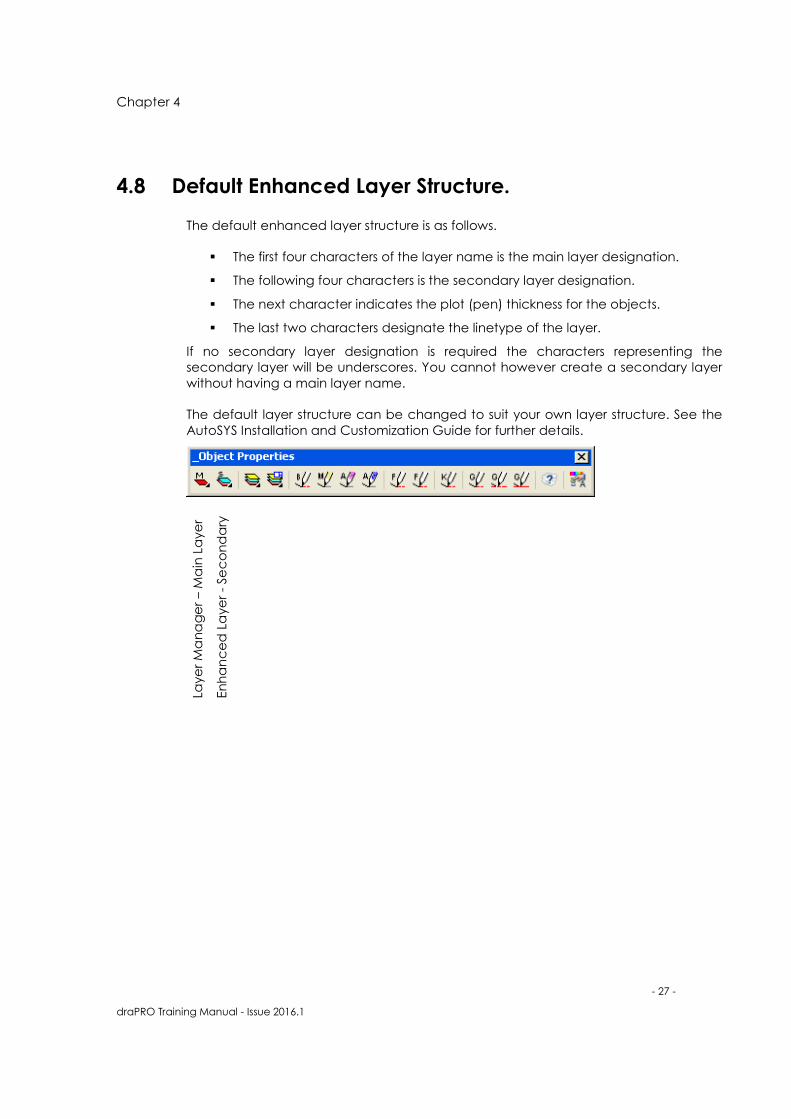
4.8 Default Enhanced Layer Structure.
The default enhanced layer structure is as follows.
� The first four characters of the layer name is the main layer designation.
� The following four characters is the secondary layer designation.
� The next character indicates the plot (pen) thickness for the objects.
� The last two characters designate the linetype of the layer.
If no secondary layer designation is required the characters representing the
secondary layer will be underscores. You cannot however create a secondary layer
without having a main layer name.
The default layer structure can be changed to suit your own layer structure. See the
AutoSYS Installation and Customization Guide for further details.
Laye
r M
an
ag
er
– M
ain
La
ye
r
En
ha
nc
ed
La
ye
r -
Se
co
nd
ary

Chapter 4
- 28 -
draPRO Training Manual - Issue 2016.1
4.9 Setting an Enhanced Layer.
These are some of the tool buttons you can use for creating Enhanced Layers as
explained below.
To set a draPRO Enhanced Layer
1. Select the Layer Manager button from the Object Properties toolbar. The
following dialog box appears.
2. From the Extended Layers area, SELECT the Select button.

Chapter 4
- 29 -
draPRO Training Manual - Issue 2016.1
3. From the Main Layer area, SELECT Gearbox.
4. From the Secondary Layer area, SELECT Shaft.
5. SELECT OK. The AutoSYS Layer Control dialog box will re-appear.
6. From the Pen Size area, SELECT 0.35 radio button
7. From the Line Type area, SELECT Continuous.
8. The full enhanced layer name will be displayed in the Layer Name area as
you make changes.
9. SELECT OK.
New layers can be set with the same main and secondary layer name designation by:
10. Specifying a different pen size in the draPRO Layer Control dialog box.
11. Specifying a different linetype in the draPRO Layer Control dialog box.
12. Selecting a basic layer from the either the Layer pull-down menu, or Layer
tablet menu.
To set a layer with the current main and secondary layer names:
13. SELECT the Layer Manger tool button from the Object Properties toolbar.
14. From the Pen Size area, SELECT 0.35 radio button.
15. From the Line Type area, SELECT Hidden from the list.
16. SELECT OK.

Chapter 4
- 30 -
draPRO Training Manual - Issue 2016.1
4.10 Creating Enhanced Layers “On The Fly”.
Another way to create enhanced layers is to select the Main & Secondary layer
names and then choose the pen size and start drawing. The layer will be created
automatically. The current Main & Secondary layer names are displayed in the lower
left hand corner of the screen.
The current Main & Secondary Layer Names
To set a draPRO enhanced layer
1. SELECT the Enhanced Layer tool button from the Object Properties toolbar.
2. SELECT General for the Main layer and New None as the Secondary layer.
3. SELECT General and None as the layers.
4. SELECT OK.
See how the layer names are displayed in the lower left hand corner as shown below.
However, there has not yet been a layer created with that name as the pen size and
line type have not been selected.
What your Status Bar should look like.

Chapter 4
- 31 -
draPRO Training Manual - Issue 2016.1
Pen Buttons
SELECT one of the Pen buttons and start drawing.
The layer will be created using the current enhanced layer names and the pen size
that you choose.
You can create a different linetype by choosing one of the linetype buttons. This also
creates a layer using the current enhanced layer names.
4.11 Adding NEW Enhanced Layer Names.
The only way to add more and new enhanced Main & Secondary layer names to the
available lists is through the client definition files. This is available under AutoSYS
Preferences and is covered in a later chapter.
4.12 Setting a Layer Current by Selecting an Object.
Once you have created an object on a layer you can quickly set the current layers
by selecting an object on that layer.
To set a layer current by selecting an object
1. From the Object Properties toolbar, SELECT the Global Layer Control Flyout
menu. Then SELECT change to current layer.
2. SELECT an object on the layer you want to set current.

Chapter 4
- 32 -
draPRO Training Manual - Issue 2016.1
4.13 Worked Example.
1. SELECT the Layer Manager button from the Object Properties toolbar.
2. SELECT the Select button in the middle of the dialog in the Extended Layer
area.
3. SELECT the following layers: Main Layer - Communications
Secondary - Seals
4. SELECT OK.
5. Now SELECT the 0.25 radio button and HIGHLIGHT the Doule Dashed Linetype.
Note that the layer name is DUCTN___2DH, similar to below.
6. SELECT OK.
You are returned to the drawing editor and the current layer is now set to
DUCTN____2DT. Draw a line and it will be drawn on this new enhanced layer you
have just created.
Note also that in the lower left hand corner the layer names [DUCTWORK] [NEW
NONE] are displayed as shown here.

Chapter 4
- 33 -
draPRO Training Manual - Issue 2016.1
We will now create another layer in a different way.
1. SELECT a Pen from the buttons in the Object Properties toolbar.
2. SELECT the 0.5 Pen. This has created a layer and put you into the line
command - draw a line.
3. Have a look at the command line and you will see the layer DUCTN___5CO
has been created and it was also set current for you too.
Whatever layer names are displayed at the bottom - they are the layers that will be
created. That’s all there is to creating enhanced layers, it is very easy and user
friendly.
4. SELECT the Layer Manager Button from the Object Properties toolbar.
5. To REMOVE the enhanced layer feature, SELECT the Main layer and
Secondary layer both to none, as shown below
6. SELECT OK.
7. See how the layer names are displayed in the lower left hand corner as
shown below.

Chapter 4
- 34 -
draPRO Training Manual - Issue 2016.1

Chapter 5
- 35 -
draPRO Training Manual - Issue 2016.1
Application Loader
Chapter Introduction
This chapter covers the following topics:
5.1 Appliaction Loader Basics.
5.2 The Application Loader Toolbar.
5.3 Unloading an Application.
5.4 Setting an Application to Autoload.
5
In this chapter
After completing this chapter,
you will be able to
� Use the Application
toolbar.
� Unload and load
Application.
� Autoload Applications.

Chapter 5
- 36 -
draPRO Training Manual - Issue 2016.1
5.1 Application Loader Basics.
The Application Loader is a utility that allows any number of 3rd party applications to
be loaded into an AutoCAD drawing session at the same time. Some features and
benefits of the Application Loader are:
� Have one or more applications run in the same drawing session at the same
time.
� Automatically load default applications, each time a drawing is edited.
� Fully unload applications from the editing session at any time.
� Re-load those applications that were used to create a drawing each time
that drawing is edited.
5.2 The Application Loader Toolbar.
The Application Loader will load automatically when AutoCAD loads. The various
functions can be selected from the AutoCAD command line in all AutoCAD versions
or from the Application Loader toolbar.
Loading an application
� To load an application using the Application Loader the application needs to
be registered with the Application Loader.
To load an application
1. From the Application Loader toolbar, SELECT the Load or Unload button.
2. From the Application List box, SELECT the application to load.

Chapter 5
- 37 -
draPRO Training Manual - Issue 2016.1
3. SELECT OK.
The chosen application will now be loaded.
5.3 Unloading an Application.
To Unload an application using The Application Loader.
1. From the Application List box, SELECT the application to unload.
2. SELECT the Unload Selected Application box.
3. SELECT OK.
The chosen application will now be unloaded.
5.4 Setting an Application to Autoload
1. From the Application Loader toolbar, SELECT the Preferences button. This will
display the Applications Preferences dialog box.
2. HIGHLIGHT the application you wish to have auto loading.
3. SELECT the Autosave box to automatically load the displayed application
every time you load AutoCAD.
4. Be sure to SELECT the SAVE button to save the change.
You can view the configuration of a registered application by making a selection
from the Registered Application List box. The Autoload status will be displayed for the
selected application.

Chapter 5
- 38 -
draPRO Training Manual - Issue 2016.1

Chapter 6
- 39 -
draPRO Training Manual - Issue 2016.1
draPRO
Chapter Introduction
This chapter covers the following topics:
6.1 draPRO Base.
6.2 To Load a Building Services Module.
6.3 draPRO Base Additional Flyouts.
6.4 Setting a draPRO Application to Autoload.
6.5 Quick Keys.
6
In this chapter
After completing this chapter,
you will be able to
� Using draPRO tools.
� Getting arround builds
services components.
� Autoload Applications.
� Quick Keys.
Chapter 6
- 40 -
draPRO Training Manual - Issue 2016.1
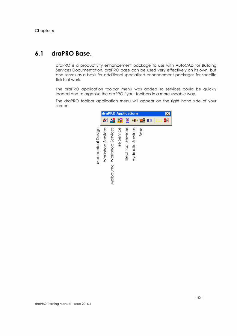
6.1 draPRO Base.
draPRO is a productivity enhancement package to use with AutoCAD for Building
Services Documentation. draPRO base can be used very effectively on its own, but
also serves as a basis for additional specialised enhancement packages for specific
fields of work.
The draPRO application toolbar menu was added so services could be quickly
loaded and to organise the draPRO flyout toolbars in a more useable way.
The draPRO toolbar application menu will appear on the right hand side of your
screen.
Me
ch
an
ica
l De
sig
n
Wo
rksh
op
Se
rvic
es
Me
lbo
urn
e
Wo
rksh
op
Se
rvic
es
Fire
Se
rvic
e
Ele
ctr
ica
l Se
rvic
es
Hyd
rau
lic S
erv
ice
s
Ba
se

Chapter 6
- 41 -
draPRO Training Manual - Issue 2016.1
6.2 To Load a Building Services Module.
1. SELECT the service you wish to use (load), from the draPRO Applications
toolbar above.
2. The fly-out toolbar for the selected service will be displayed below (or in the
last position you moved it to).
3. Then SELECT application toolbar, replace any previously selected service from
the draPRO application toolbar.
4. The selected service is now loaded and ready to use.
5. Once a service has been loaded, the pulldown menu for the service is also
available.
6. From the pulldown menu you can SELECT draPRO commands, display specific
toolbars, or set the service tablet menu to be the current. Help for the specific
service is also via the pulldown menus.
7. SELECT the Mechanical Design button from the draPRO Applications toolbar.
8. The above draPRO toolbar application menu with Mechanical Design
services shall Load and appear on your screen.
Any draPRO services loaded when you save the drawing will automatically get
loaded the next time you open the drawing. If you don’t want a service to load
automatically use the load or unload (DPQ_EXECUTE) command from the
Application Loader toolbar to unload it before you exit (and save) the drawing.
Of course you can still use the load or unload command from the Application Loader
tools to load any draPRO service instead of using the draPRO Applications toolbar.

Chapter 6
- 42 -
draPRO Training Manual - Issue 2016.1
6.3 draPRO base additional Flyouts.
The below draPRO Base toolbars can be accessed by SELECTING the Base button
from the draPRO Applications toolbar. These toolbars cover the Architectural drawing
and clean up in the draPRO package.
6.4 Setting a draPRO application to Autoload.
The Autoload section can be utilized to stop reloading the draPRO Applications
which are required each time a drawing is started or re-opened.
1. From the Application Loader toolbar, SELECT the Preferences button. This will
display the Applications Preferences dialog box.
2. HIGHLIGHT the application you wish to have auto loading. Eg: Mechanical
design (draPROmd)
3. SELECT the Autosave box to automatically load the displayed application
every time you load AutoCAD.
4. Be sure to SELECT the Save button to save the change.

Chapter 6
- 43 -
draPRO Training Manual - Issue 2016.1
6.5 Quick Keys.
draPRO customises a number of the keys on the keyboard to functions. This makes
the selection of standard AutoCAD and draPRO commands easier to use.
Function quick keys
� Osnap Quick Keys
� Function Keys
� Number Quick Keys
� Letter quick Keys
Osnap Quick Keys
These keys provide quick access to AutoCAD osnap commands. To use the following
quick key commands, type the indicated key, or combination of keys.
The numbers on the numeric keypad have been mapped as follows
["NUMPAD0"]_int Intersection
["NUMPAD1"]_endp End point
["NUMPAD2"]_near Near point
["NUMPAD3"]_cen Centre
["NUMPAD4"]_mid Midpoint
["NUMPAD5"]_app Intersection
["NUMPAD6"]_quad Quadrant
["NUMPAD7"]_perp Perpendicular
["NUMPAD8"]_int Intersection
["NUMPAD9"]_tan Tangent
To turn functions Osnap Quick Keys on & off please refer to functions keys.
Chapter 6
- 44 -
draPRO Training Manual - Issue 2016.1
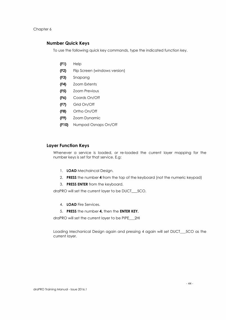
Number Quick Keys
To use the following quick key commands, type the indicated function key.
{F1} Help
{F2} Flip Screen (windows version)
{F3} Snapang
{F4} Zoom Extents
{F5} Zoom Previous
{F6} Coords On/Off
{F7} Grid On/Off
{F8} Ortho On/Off
{F9} Zoom Dynamic
{F10} Numpad Osnaps On/Off
Layer Function Keys
Whenever a service is loaded, or re-loaded the current layer mapping for the
number keys is set for that service. E.g:
1. LOAD Mechaincal Design.
2. PRESS the number 4 from the top of the keyboard (not the numeric keypad)
3. PRESS ENTER from the keyboard.
draPRO will set the current layer to be DUCT___5CO.
4. LOAD Fire Services.
5. PRESS the number 4, then the ENTER KEY.
draPRO will set the current layer to be PIPE___2HI
Loading Mechanical Design again and pressing 4 again will set DUCT___5CO as the
current layer.

Chapter 6
- 45 -
draPRO Training Manual - Issue 2016.1
Letter Quick Keys
To use the following quick key commands, type the indicated key or combination of
keys and press {RETURN}
{A} Arc.
{A}{R} Array.
{B} Break.
{C} Copy.
{C}{B} Change Both = Change both colour and linetype of an entity to
by bylayer.
{C}{T} Change Text = Change whole text string to new string.
{D} Distance.
{D}{T} Dtext.
{E} E Rase.
{E}{E} Explode.
{E}{L}{L} Ellipse.
{F} Fillet.
{F}{F} Multiple Fillet = Fillet multiple lines at once.
{G}{R} Grow Line = Extend line by a length.
{H} Hatch.
{I} Insert.
{L} Line.
{L}{L} Ployline.
{L}{C} Layer Current = Changes selected entities to current layer.
{L}{E} Leader.
{L}{E}{E} Layer Explode = Explode entity and change layer of exploded
entity to the layer of entity before exploding it.
{L}{F} Layer Freeze.
{L}{N} Layer New.
{L}{O} Layer Off.
{L}{S} Layer Set.
{M} Move.
{M}{R} Mirror (delete original).
{M}{R}{R} Mirror (don't delete original).
{N} Trim Pick = Trim line between two crossing lines.
{O} Offset.
{P} Change Properties.

Chapter 6
- 46 -
draPRO Training Manual - Issue 2016.1
{Q} List Item.
{R} Rotate.
{S} Rotate Cross Hairs to Pick = Rotate cursor to angle of selected
entity.
{S}{0} Rotate Cross Hairs to Zero = Rotate cursor to angle zero degrees.
{S}{4} Rotate Cross Hairs to 45 Degrees = Rotate cursor to angle 45
degrees.
{S}{N} Rotate Cross Hairs to Angle = Rotate cursor to angle typed from
keyboard.
{S}{C} Scale.
{S}{L} Solid.
{S}{S} Stretch.
{T} Trim.
{T}{B} Break Text = Break text string.
{T}{C} Continue Text.
{T}{E} Edit Text.
{T}{T} Multiple Trim.
{U} Undo.
{W}{B} Wblock.
{X} Extend.
{X}{L} Extend Line.
{Z}{Z} Zoom Virtual.

Chapter 7
- 47 -
draPRO Training Manual - Issue 2016.1
Model/Paper Format
Drawing
Chapter Introduction
This chapter covers the following topics:
7.1 Working in Paper/Model Space.
7.2 Paper/Model.
7.3 Advantages.
7.4 Disadvantages.
7.5 Model Space Viewport Boundaries
Explained.
7.6 Using Model Space Viewport Boundaries.
7.7 Dimensioning in Bounding Boxes.
7.8 Rescale Bounding Boxes.
7.9 Displaying Bounding Boxes Settings.
7.10 Highlight current Viewport Bounding Box.
7.11 Creating a Paper Space Viewport.
7
In this chapter
After completing this chapter,
you will be able to
� Use scaled areas and view
ports..
� Place text in Model Format
Drawings
� Place dimension in Model
Format drawings.
� Place Blocks scaling and
non scaling in Model
Format drawings.

Chapter 7
- 48 -
draPRO Training Manual - Issue 2016.1
7.1 Working in PAPER/MODEL Space.
Creating floating viewports in paper space has many advantages. Usually
associated with 3D drawings, floating viewports can also be used effectively in 2D
drawings. One of the advantages of paper space is that you can have many views
on the one model, all at different scales if necessary.
These views can be thought of as windows (floating viewports) cut through your
paper (space) onto your model (space). Each floating viewport can reflect a detail
of any rectangular portion of the model, at any scale. This of course can be helpful
because instead of having a copy of a detail at a different scale in your drawing,
you have a view onto the original model. Plainly any changes to be made are only
necessary on the model, and additional editing to update a copy of a detail is not
needed.
A number of techniques need to be understood to effectively use paper/model
space. Lets cover these now, draPRO provides a number of additional functions to
enhance AutoCAD's commands for controlling floating viewports, which make using
paper/model space more manageable.
The method or combination of methods you choose to produce your drawing will
depend on the job at hand and how your system administrator feels. Whichever
method you choose, be assured that draPRO will make the job easier. All that is
required is to select what you want and draPRO will do the scaling and layering
necessary to get the correct final result.
7.2 Paper/Model - Each Viewport Looks at a Unique Portion
of a Model Space Drawing.
draPRO is designed to work with 2D drawings with all model objects (Arch plan, duct
etc) to be drawn in model space along with text, dimensions and annotation symbols
used to describe the model object is also drawn in model space. The title sheet and
title labels however are drawn in paper space.
Each section of the drawing in model space is contained in a model space
bounding box. This draPRO object has a viewport and detail scale factor attached to
it and when drawing in that space the scaling of annotations is controlled so as to
appear correctly when viewed in a floating paper space viewport.

Chapter 7
- 49 -
draPRO Training Manual - Issue 2016.1
7.3 Advantages.
• All drawing work can be achieved with the use of transparent zoom and pan
commands.
• Dimensioning is fully controlled as model and annotations are in the same space
• Display scaling is controlled by the viewport scale
• No viewport linear scale factor need be applied to the dimension style before
dimensioning (DIMLFAC=1.0).
7.4 Disadvantages.
• It is not how the system was designed to work and later versions of AutoCAD may
require modification.
• Difficult to work with if not using draPRO.
7.5 Model Space Viewport Boundaries Explained.
Model space viewport bounding boxes are special draPRO Objects (polyline
rectangles with extended data attached), that enclose an area of the drawing in
model space that will be displayed in a floating viewport at a particular scale setting.
A viewport bounding box is a link between views of objects in model space with
tilemode ON and floating viewports displayed with tilemode OFF. The scale setting
attached to the bounding box, is the scale at which annotations are scaled when
placed in the viewport bounding box.
A viewport bounding box also allows objects that would normally be drawn full size,
(all model objects should be drawn full size) to be scaled up for details in model
format drawings.
At any time during the drawing process a viewport bounding box will be marked as
active. If there are no viewport bounding boxes then the current drawing scale is
used as the annotation scale.
When placing annotations draPRO will scale the object based on either:
• The scale of the viewport bounding box the object is placed in if, tilemode is
ON and the drawing is in draPRO paper/model format.
• The scale of the active floating model space viewport if, tilemode is OFF and
the drawing is in draPRO paper/model format.
• The 1:1 scale if tilemode is OFF and you are in paper space and the drawing is
in AutoSYS paper/model format.
• The scale of the drawing if, tilemode is ON and the drawing is in draPRO model
format.
For all annotations except dimensions, draPRO will automatically sense the location
and scale the objects accordingly.

Chapter 7
- 50 -
draPRO Training Manual - Issue 2016.1
Dimensioning however is handled differently, due to the way AutoCAD places
dimensions either by selecting points or selecting objects.
If working with tilemode ON and you are in a paper/model format drawing, an
active viewport must be set before placing dimensions. Dimensioning must be
performed in the active viewport bounding box. If no active viewport is set then the
drawing scale will be used by default.
If working with tilemode OFF and dimensioning in either paper or model space the
dimension scale is handled automatically by the scale of the current floating
viewport or the paper scale, the active viewport bounding box is ignored.
7.6 Using Model Space Viewport Boundaries.
Creating a Model Space Viewport Bounding box
1. TOGGLE to model space by SELECTING Model button from the layout tab
section.
2. From the Model Space Viewport toolbar, SELECT the Create Viewport
Bounding box button.
Mo
de
l sp
ac
e v
iew
po
rt
Re
sca
le B
ou
nd
ing
bo
x
Cre
ate
Pa
pe
r sp
ac
e v
iew
po
rt
Dis
pla
y b
ou
nd
ing
bo
x D
eta
ils
Se
t C
urr
en
t b
ou
nd
ing
bo
x
Hig
hlig
ht
cu
rre
nt
bo
un
din
g b
ox

Chapter 7
- 51 -
draPRO Training Manual - Issue 2016.1
3. PICK two points to draw a rectangle.
The following dialog will be displayed allowing you to specify the viewport scale,
enlargement factor and block scale.
4. The viewport scale will show (by default), the current drawing scale. From the
popup list choose the scale for the viewport.
5. The enlargement factor works with dimension values so when objects have
been scaled up in a viewport the enlargement factor scales dimension values
by the specified factor. E.g. If you have two model space bounding boxes,
(a) has a viewport scale = 100, enlargement factor = 1
(b) has a viewport scale = 100, enlargement factor = 2
A line drawn 8000mm in viewport (a) will be dimensioned 8000mm, while a
line drawn 16000mm in viewport (b) will be dimensioned 8000mm.
6. Enter a block scaling factor. The block scaling factor scales up or down any
block inserted using a draPRO function.
The new viewport bounding box will be made active. That is all dimensions done from
now on will reflect the parameters set for this box.

Chapter 7
- 52 -
draPRO Training Manual - Issue 2016.1
7.7 Dimensioning in Bounding Boxes.
Before you dimension in a bounding box you must set it current.
1. From the Model Space Viewport toolbar, SELECT Set the Current Viewport
Bounding box.
2. PICK a point inside a bounding box.
3. The scale is now set to the scale stored in that viewport bounding box.
If you inadvertently place dimensions on the non scaled parts of the drawing the
dimension format will be wrong. These dimensions can be easily updated to reflect
the correct values.
4. To set the scale back to the drawing scale (as set when the drawing was
created), use the Set Current Viewport Bounding box command and SELECT
a point outside any existing bounding boxes.
5. Place dimensions as normal.
Remember ONLY dimensions require you to set the active viewport bounding box.
7.8 Rescaling Bounding Boxes.
Existing viewport bounding boxes can be rescaled using the Re-scale Viewport
Bounding box function.
1. From the Model Space Viewport toolbar, SELECT Re-scale Viewport Bounding
Box.
Se
t C
urr
en
t V
iew
po
rt

Chapter 7
- 53 -
draPRO Training Manual - Issue 2016.1
2. SELECT the bounding box to rescale. The AutoSYS Model Space Viewport
Boundary dialog box is displayed showing the current settings for the
bounding box.
3. EDIT as required and SELECT OK.
7.9 Displaying Bounding Box Settings.
1. From the Model Space Viewport toolbar, SELECT Display Viewport Bounding
box details.
2. PICK a point inside a bounding box.
An AutoCAD message dialog box is displayed showing the settings for the bounding
box selected.
3. SELECT OK to continue.
7.10 Highlight Current Viewport Bounding Box.
1. From the Model Space Viewport toolbar, SELECT Highlight Current Viewport
Bounding box.
An AutoCAD Message dialog box is displayed showing the settings for the current
bounding box.
2. SELECT OK to continue. The current bounding box will be HIGHLIGHTED.
7.11 Creating a Paper Space Viewport from a Model Space
Bounding Box.
Having created bounding boxes and drawn in them you will want to create paper
space viewports based on them.
1. TOGGLE tilemode OFF by double clicking TILE in the status line. You will be
placed in Paper space.
2. From the AutoSYS Viewport Utilities toolbar, SELECT the Create Viewports
function.

Chapter 7
- 54 -
draPRO Training Manual - Issue 2016.1
3. First point: Pick a point
4. Second point: Pick another point to draw a rectangle
The size of the viewport is not important, as the size is taken from the model space
viewport bounding box.
5. Show isometric (Y or N) <Yes> :No
Entering YES, allows you to view the model space view in a SW aspect.
6. SELECT a point or ENTER to select a view port bounding box. Pick a point inside
a model space viewport bounding box
7. Is this Orientation correct?(Y or N) <Yes> :Yes
Entering NO rotates the view 90 degrees.
Changing Viewports to layer DPQ_MODELPORT
The viewport created now has the same properties (scale & size), of the model space
viewport bounding box it was based on. You can choose to draw in the new paper
space viewport, or toggle back to model space.
Cre
ate
pa
pe
r sp
ac
e v
iew
po
rt
Chapter 8
- 55 -
draPRO Training Manual - Issue 2016.1
Getting around the
draPRO features
Chapter Introduction
This chapter covers the following topics:
8.1 Menu Bar.
8.2 Toolbars.
8.3 Dialog Boxes.
8.4 Online Help.
8
In this chapter
After completing this chapter,
you will be able to
� Use the different
commands and dialogs in
the draPRO environments

Chapter 8
- 56 -
draPRO Training Manual - Issue 2016.1
8.1 Menu Bar.
The menu bar for each draPRO service is located at the top of the AutoCAD
application window.
Several of the options on the menus contain related menus; these submenus provide
further command options. A small black arrowhead to the right of a menu option
indicates that an option has a submenu, or a cascading menu.
Experiment with the functionality of the items in these menus

Chapter 8
- 57 -
draPRO Training Manual - Issue 2016.1
8.2 Toolbars.
The draPRO toolbars consist of a collection of tools relating to the task in which they
perform. They are broken up into the Building Service they relate to and the item they
are drawing. Eg: Rectangle Ductwork toolbar and Spiral Ductwork toolbar.
.
Straight Duct
Flexible Connection
Fire Damper
Square Bend
Radius Bend
Equal Transition
Flat Transition
Offset Transition
Shoe
Three Way Tee
Radius Tee
Turning Vanes
Radius Take off
Three way tee
Dropper
Riser/Dropper
Humidifier
Water Coil
Electric Heater
AutoDUCT
Detach Toolbar
REC
TAN
GLE
DU
CTW
OR
K T
OO
LBA
R

Chapter 8
- 58 -
draPRO Training Manual - Issue 2016.1
8.3 Dialog Boxes.
When you select a menu from draPRO for the drawing of ductwork there are various
input methods available for the different features of drawing ductwork.
Pick New Start Point.
Allows you to specify a new start point for the duct piece to be drawn. If you wish to
pick a start point from an existing duct piece, select the duct end using midpoint
snap. This has the effect of picking up the duct sizes from the existing duct piece, and
making them the defaults for the air on duct sizes in the dialog box.
Run Angle.
Displays the current duct run angle. Specify a new run angle to override the default
Air On.
Displays the current settings for the air on duct values, for the duct piece being
drawn. Eg: The air off values of the previously drawn duct piece. Specify new values
in the edit boxes.
Duct Length.
The duct length can be specified graphically by selecting distance on the screen. A
rubber band will indicate the start point of the duct, the angle will be that of the
current run angle, as long as ortho mode is on.

Chapter 8
- 59 -
draPRO Training Manual - Issue 2016.1
Insulation.
Displays the current setting for insulation. Selecting a new insulation will update the
duct image with the corresponding insulation type.
List Insertion.
Another method of insertion inside draPRO is for inserting blocks from a List. Eg: Grilles.
This dialog box displays a list of all the blocks that can be inserted off the menu
button. By SELECTING the Edit button, you can add additional blocks to the list.
8.4 Online Help
Familiarise yourself with the extensive Help documentation that you can access in
draPRO. You will find the Help documents at the bottom of each draPRO menu pull
down.


![Skaffold - storage.googleapis.com · [getting-started getting-started] Hello world! [getting-started getting-started] Hello world! [getting-started getting-started] Hello world! 5](https://img.dokumen.tips/doc/110x75/5ec939f2a76a033f091c5ac7/skaffold-getting-started-getting-started-hello-world-getting-started-getting-started.jpg)