Embed Size (px)
Citation preview

Distribution: Electronic Only Initiated By: AFS-420
CHANGE U.S. DEPARTMENT OF TRANSPORTATION FEDERAL AVIATION ADMINISTRATION
8260.3B CHG 21
National Policy Effective Date: June 5, 2009
SUBJ: United States Standard for Terminal Instrument Procedures (TERPS)
1. Purpose. Order 8260.3B, United States Standard for Terminal Instrument Procedures (TERPS), contains criteria that must be used to formulate, review, approve, and publish procedures for instrument approach and departure of aircraft to and from civil and military airports. These criteria are for application at any location over which the Federal Aviation Administration (FAA) or Department of Defense (DoD) exercises jurisdiction.
Note: This change revises criteria in Volume 1, chapter 2 regarding final approach segment descent angles and circling maneuvering areas, updates table 3-5a in Volume 1, chapter 3, replaces criteria in Volume 1, chapter 10 for Radar approaches and Minimum Vectoring Altitude Charts (MVAC), and revises Volume 3, chapter 3 criteria relating to the Glideslope Qualification Surface (GQS).
2. Distribution. This change is distributed in Washington Headquarters to the branch level in the Offices of Aviation Research and Airport Safety and Standards, the Air Traffic Organization (Safety, En Route and Oceanic Services, Terminal Services, and Technical Operation Services), and Flight Standards Service; to the National Flight Procedures Office and the Regulatory Standards Division at the Mike Monroney Aeronautical Center; to the branch level in the regional Flight Standards and Airports Divisions; to the Technical Operations Service Areas and Air Traffic Service Areas; special mailing list ZVS-827, and to special military and public addressees.
3. Effective Date. August 27, 2009.
4. Explanation of Changes. Significant areas of new direction, guidance, policy, and criteria as follows:
A. Volume 1, Chapter 2, General Criteria. The chapter is revised to incorporate guidance from TERPS Instruction Letters (TILs) 99-014 and 00-012A which are rescinded. Additionally, it revises circling approach area criteria to resolve Government/Industry Aeronautical Charting Forum (ACF) issue #92-02-105. The criteria also includes the recommendations of the United States Instrument Flight Procedures Panel (US-IFPP) Change 21 Working Group to improve internal consistency and coherence.

06/05/2009 8260.3B CHG 21
Page 2
1) Section 5, Final Approach.
a) Provides clarification of intent related to vertical descent angle (VDA) and removes redundant requirements related to final approach segment descent gradient.
b) Provides updated guidance related to the range of acceptable VDAs and revises/clarifies criteria and figures for VDA calculations in straight-in and circling aligned approach cases (with and without stepdown fix) incorporating updated terminology and formulas.
c) Updates guidance for establishing, calculating, and marking the Visual Descent Point (VDP), with consideration to procedures with multiple lines of NPA minima.
2) Section 6, Circling Approach.
a) Updates requirements related to the Circling Approach Area, revising the method of determining the size of the Obstacle Evaluation Area (OEA) to more closely align with ICAO methodology based ACF issue #92-02-105.
b) Clarifies intent related to OEA evaluation when circling area restrictions are established based on ACF issue #92-02-105 and US-IFPP Change 21 Working Group recommendations.
3) Section 7, Missed Approach. Updates terminology and clarifies design elements specified in the missed approach.
B. Volume 1, Chapter 3, Takeoff and Landing Minimums. The chapter is revised to incorporate guidance from the March 14, 2008 memorandum subject: Equivalent Meter Runway Visual Range (RVR) and Visibility with RVR less than 2400 Authorized, which is rescinded. The revision replaces table 3-5a (including footnotes) in its entirety.
C. Volume 3, Chapter 10, Radar Procedures. The chapter is revised in its entirety to incorporate guidance from the canceled Notice 8260.64, Radar Approaches and Minimum Vectoring Altitudes - Current Guidance and Criteria. It also includes guidance from the July 21, 2008 AFS-400 memorandum subject: Use of Automated Precipitous Terrain Algorithms for Minimum Vectoring Altitude (MVA) and Minimum Instrument Flight Rules (IFR) Altitude (MIA) Required Obstacle Clearance (ROC) Reductions and the September 10, 2008 AFS-400 memorandum subject: Interim Criteria for Radar Approaches and Minimum Vectoring Altitudes and Guidelines for Application of Glidepath Qualification Surface. These memorandums are rescinded. The criteria also includes the recommendations of the United States Instrument Flight Procedures Panel (US-IFPP) Change 21 Working Group to improve internal consistency and coherence.
D. Volume 3, Chapter 2, General Criteria. The chapter is revised to incorporate guidance from the canceled Notice 8260.65, Guidelines for Application of Glidepath Qualification Surface (GQS) and the September 10, 2008 AFS-400 memorandum subject: Interim Criteria for Radar Approaches and Minimum Vectoring Altitudes and Guidelines for Application of Glidepath Qualification Surface which is rescinded. The criteria also includes the recommendations of the

06/05/2009 8260.3B CHG 21
Page 3
United States Instrument Flight Procedures Panel (US-IFPP) Change 21 Working Group to improve internal consistency and coherence.
1) Paragraph 2.9.1, Distance Measure Equipment (DME) incorporates guidance from the December 12, 2005 AFS-420 memorandum subject: Clarification of Issues Related to Criteria Coordination Committee Agenda Items related to issue 04-CCC-010.
2) Paragraph 2.11, Clear Areas and Obstacle Free Zones (OFZ) is intentionally deleted in its entirety.
3) Paragraph 2.12, Glidepath Qualification Surface (GQS) is renumbered paragraph 2.11, and:
a) All criteria and figures revised to clarify that the GQS area originates at the runway threshold, even when the sloping OCS is offset (i.e., low TCH case).
b) Paragraph 2.11.1 text and formulas updated to accommodate vertically guided RNAV procedures (especially those with multiple lines of minima). It specifies that the assessment(s) of a GQS sloping surface be consistent with the vertical characteristics of each glidepath associated with the procedure/line of minima.
c) Paragraph 2.11.1d(2) and figure 2-5g clarifies intent regarding permitted obstacles (i.e., excluded from consideration during GQS evaluation).
4) Paragraph 2.13, ILS/MLS Critical Areas was deemed irrelevant to TERPS evaluations and intentionally deleted.

06/05/2009 8260.3B CHG 21
Page 4
PAGE CONTROL CHART
Remove Pages Dated Insert Pages Dated Volume 1, Chapter 2 Volume 1, Chapter 2 21 02/13/1998 21 thru 26-2 06/05/2009 22, 23 05/15/2002 24 11/12/1999 25, 26 05/15/2002 26-1, 26-2 11/12/1999
Volume 1, Chapter 3 Volume 1, Chapter 3 3-21 thru 3-22 12/07/2007 3-21 thru 3-22 06/05/2009
Volume 1, Chapter 10 Volume 1, Chapter 10 87 thru 98 10-1 thru 10-18 06/05/2009
Volume 3, Chapter 2 Volume 3, Chapter 2 2-11 thru 2-16 05/15/2002 2-11 thru 2-18 06/05/2009
John M. Allen Director, Flight Standards Service
2/13/98 8260.3B CHG 17
Chap 2 Page 21 Par 244
(3) Intermediate Segment Area.
(a) PT Over a Facility. The intermediate segment starts 15 NM from the facility at a width of 6 NM each side of the inbound course and connects to the width of the final segment at the FAF. The area considered for obstacle clearance is from the start of the PT distance to the FAF.
Figure 14-2. Intermediate Area Within
PT Area. PT Facility/Fix
Used as a Stepdown Fix [Par 244d(4)].
(b) PT Over a Fix (NOT a Facility). The intermediate segment starts at the PT distance at a width of 6 NM each side of the inbound course and connects to the width of the final segment at the FAF. The area considered for obstacle clearance is from the start of the PT distance to the FAF.
(4) The MAXIMUM descent gradient is 200 ft/NM. If the PT facility/fix is a stepdown fix, the descent gradient from the stepdown fix to the FAF may be increased to a maximum of 318 ft/NM (see figure 14-2). The PT distance may be increased in 1 NM increments up to 15 NM to meet descent limitations.
(5) When establishing a step-down fix within an intermediate/initial segment underlying a PT area:
(a) When the PT fix is over a facility/fix prior to the FAF, the facility/fix is the stepdown fix in the intermediate/initial area, and another stepdown fix within this segment is not authorized.
(b) The MAXIMUM descent gradient from the IF point to the stepdown fix is 200 ft/NM. The MAXIMUM descent gradient from the stepdown fix to the FAF is 318 ft/NM.
e. PT Facility Fix Used as an IF. See figure 14-3.
(1) When the PT inbound course is the same as the intermediate course, either paragraph 244d may be used, or a straight initial segment may be used from the start of the PT distance to the PT fix.
Figure 14-3. Use of PT Fix or IF
[Par 244e].
(2) When the PT inbound course is NOT the same as the intermediate course, an intermediate segment within the PT area is NOT authorized; ONLY a straight initial segment shall be used from the start of the PT distance to the PT fix.
(3) When a straight initial segment is used, the MAXIMUM descent gradient within the PT distance is 318 ft/NM; the PT distance may be increased in 1 NM increments up to 15 NM to meet descent limitations.
(4) When establishing a stepdown fix within an intermediate/initial segment underlying a PT area:
8260.3B CHG 21 6/5/09
Page 22 Chap 2 Par 244
(a) Only one stepdown fix is authorized within the initial segment that underlies the PT maneuvering area.
(b) The distance from the PT facility/fix and a stepdown fix underlying the PT area shall not exceed 4 nautical miles (NM).
(c) The MAXIMUM descent gradient from the PT completion point (turn distance) to the stepdown fix, and from the stepdown fix to the IF, is 318 ft/NM.
f. When a PT from a facility is required to intercept a localizer course, the PT facility is considered on the localizer course when it is located within the commissioned localizer course width.
245.-249. RESERVED.
SECTION 5. FINAL APPROACH
250. FINAL APPROACH SEGMENT. This is the segment in which alignment and descent for landing are accomplished. Final approach may be made to a runway for a straight-in landing or to an airport for a circling approach. The segment begins at the Final Approach Fix (FAF)/precise final approach fix (PFAF) and ends at the missed approach point (MAP) and/or Decision Altitude (DA). Criteria for alignment, length, obstacle evaluation area (OEA), and obstacle clearance surface/evaluation are contained in the chapters/directives specific to the facility/system providing navigation guidance. A visual portion within the final approach segment is also assessed for all approaches (see Vol. 1, chapter 3, paragraph 3.3.2d).
251. RESERVED.
252. VERTICAL DESCENT ANGLE. Vertical descent angle (VDA) is normally used in this segment for non-precision procedures. Determine the VDA for all NPA procedures except those published in conjunction with vertically-guided minima or no-FAF procedures w/out stepdown fix(es). See applicable chapters/directives for guidance on no-FAF or procedures published with PA and APV minima. Optimum VDA is 3.00 degrees. Where operationally feasible, design straight-in NPA procedures (all CATs) to achieve a VDA equal to the commissioned angle of an installed visual glideslope indicator (VGSI) if within the standard VDA range. When a VGSI is not installed or not within the standard range, or final is circling aligned, design procedures at the optimum VDA when possible or within the following range:
STANDARD VERTICAL DESCENT ANGLES FAA 2.75°-3.77° (IAPS w/ ≤ CAT C mins) 2.75°-3.50° (IAPS w/ CAT D/E mins) USAF 2.50°-3.50° (All IAPS) USN 2.50°-3.77° (All IAPS)
Note 1: Minimum VDA N/A to circling only procedures.
Note 2: CAT D/E VDA above 3.50 degrees must be annotated “Not for Civil Use.”
THE CALCULATED VDA AND THE VGSI MAY BE CONSIDERED EQUIVALENT WHEN THE CALCULATED ANGLE IS ± 0.20 degrees of the VGSI angle and the TCH used for the calculation is ± 3 ft of the VGSI TCH.
For a straight-in aligned procedure, when the minimum angle has not been achieved, modify the fix location or raise the FAF/PFAF altitude.
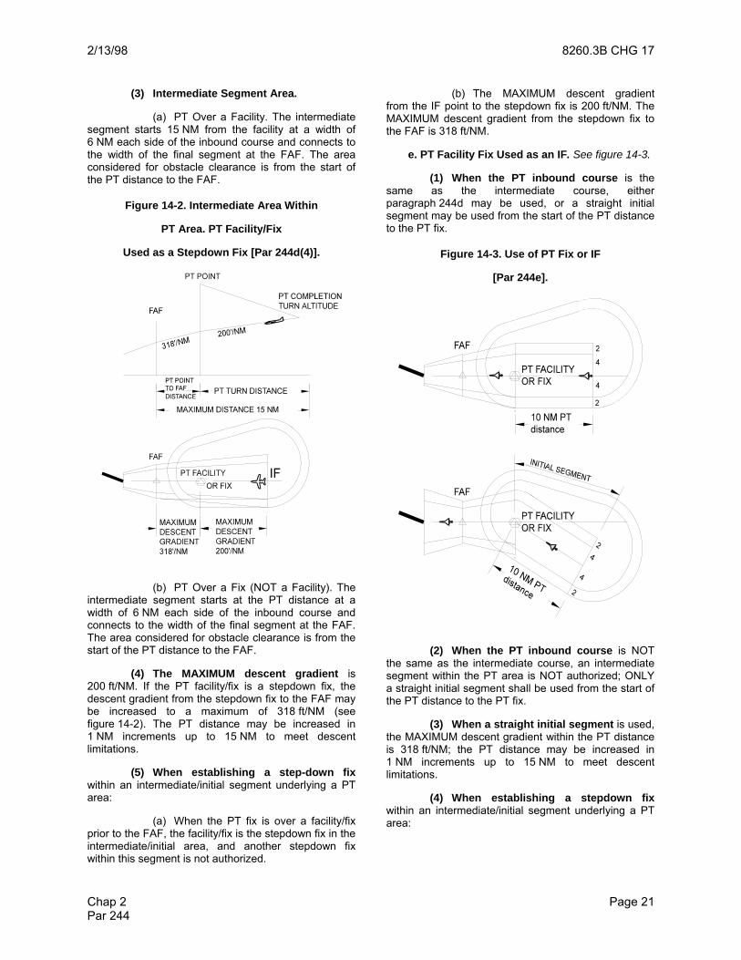
Calculate VDA based on the distance from the plotted position of the FAF/PFAF or stepdown fix to the plotted position of the final end point (FEP). The FEP is a point on the FAC equal to the distance from the FAF/PFAF to runway threshold (RWT) coordinates (or displaced threshold coordinates when applicable) or from FAF/PFAF to the edge of first usable landing surface for circling only aligned procedures. See figure 14-4.
Figure 14-4. Final End Point [Par 252].
RWT/Displaced coordinates
Final Approach Course
Final End Point (FEP)
FAF/PFAF
Shortest distance FAF/PFAFto edge of any
usable landing surface
Final Approach Course
Final End Point (FEP)
FAF/PFAF
Closed runways
AND
are not usable landing surfaces. Any portion of an open runway is considered usable landing surface, except when not available for both landing takeoff.
Straight-in alignment
Circling alignment
a. Calculating Descent Angle (procedures meeting straight-in alignment). Calculate the VDA from the FAF/PFAF altitude (or stepdown fix altitude per Vol. 1, chapter 2, paragraphs 252c(1) or 252d) to threshold crossing height (TCH) using the following formula (radian calculations):
DESCENTFIX
r alt ra tan ln
r TH Re TCH D
⎛ ⎞+⎛ ⎞θ = ⋅ ⋅⎜ ⎟⎜ ⎟+ + π⎝ ⎠⎝ ⎠
180
Where:
atan = arc tangent ln = Natural logarithm alt = FAF/PFAF alt. or 252c(1) / 252d stepdown alt. THRe= Threshold elevation r = 20890537 TCH = VGSI or Design TCH DFIX = Dist. (ft) FAF/PFAF or stepdown fix to FEP
EXAMPLE alt = 2,600 ft MSL THRe = 1,012 ft MSL TCH = 46 ft DFIX = 29,420.537 ft or 4.84 NM θDESCENT = 3.00 degrees (round to nearest 0.01 degrees)

6/5/09 8260.3B CHG 219
Chap 2 Page 23 Par 252
When the maximum VDA calculated in accordance with Vol. 1, chapter 2, paragraph 252a is exceeded and altitudes/fix locations cannot be modified, straight-in minimums are not authorized. The procedure may be approved when restricted to circling minimums IF less than or equal to maximum VDA calculated in accordance with Vol. 1, chapter 2, paragraph 252b. In this case, when VDA is published, specify the VDA calculated in accordance with Vol. 1, chapter 2, paragraph 252a (published angle MAY exceed the maximum).
(1) Determining straight-in FAF/PFAF or stepdown fix location to achieve a specified design angle. Use where fix location is flexible; e.g., FAF/PFAF or stepdown fix may be defined by an area navigation (RNAV), distance measuring equipment (DME), or intersection fix. Where a VGSI is installed and within the range of minimum/maximum VDAs, select a fix location which permits a VDA equivalent with the VGSI angle. When it is not feasible to achieve equivalency (e.g., VGSI is not within the range of acceptable angles, or VGSI is not installed), select a fix location to achieve an optimum VDA when possible or within standard VDA range. Determine the FAF/PFAF or stepdown fix location (distance from threshold to fix) using the formula in figure 14-5 (radian calculations).
Figure 14-5. Straight-In FAF/PFAF or Stepdown Fix Distance Based on Altitude and Angle [Par 252a].
+⎛ ⎞ ⋅⎜ ⎟+ +⎝ ⎠=π⎛ ⎞θ ⋅⎜ ⎟
⎝ ⎠
PFAF
r altln r
r THRe TCHD
tan180
Where:
ln = Natural logarithm alt = Minimum FAF/PFAF or stepdown fix altitude THRe = Threshold elevation TCH = VGSI or Design TCH r = 20890537 θ = VGSI or specified VDA
EXAMPLE
alt = 2,600 ft MSL THRe = 1,012 ft MSL TCH = 46.0 θ = 3.00 degrees DPFAF = 29,420.537 ft or 4.84 NM
29,420.54 or 4.84 NM
2,600’ MSL
46.0’ Reference Plane
Glidepath
1012’ MSL
Reference Plane
b. Calculating VDAs (procedures not meeting straight-in alignment or straight-in aligned procedures not authorized straight-in minimums). Calculate the VDA from the FAF/PFAF or stepdown fix altitude (Vol. 1, chapter 2, paragraphs 252c(2) or 252d) to the lowest CMDA using the following formula (radian calculations).
⎛ ⎞+⎛ ⎞θ = ⋅ ⋅⎜ ⎟⎜ ⎟+ π⎝ ⎠⎝ ⎠CIR CLED ESCEN T
FIX
r a lt r 180a tan ln
r CM D A D Where:
ln = Natural logarithm r = 20890537 alt = FAF/PFAF or Vol. 1, chapter 2, para. 252c(2) / 252d stepdown fix altitude CMDA = Lowest Published CMDA DFIX = Dist. (ft) FAF/PFAF or stepdown fix to FEP
EXAMPLE
alt = 2,900 ft MSL CMDA = 1,320 ft MSL DFIX = 29,043.83 ft or 4.78 NM θCIRCLEDESCENT = 3.11354 degrees (round to nearest 0.01 degrees)
When the MAXIMUM VDA is exceeded, relocate the PFAF/stepdown fix and/or raise the CMDA until the angle is compliant.
(1) Determining Circling FAF/PFAF location to achieve a specified design angle. Procedures designed to circling alignment standards are not normally flown using a stabilized descent from the FAF/PFAF to landing. Therefore, the FAF/PFAF location is not predicated on VDA; however, the achieved angle must not exceed the maximum VDA. Establish the FAF/PFAF location in accordance with the alignment and segment length criteria applicable to the final approach navigational aid (NAVAID) or system and calculate the circling VDA.
c. Stepdown Fixes (with FAF procedures and/or procedures published w/out PA/APV minima). Establish stepdown fixes at the lowest altitude possible that also provides obstacle clearance. When minimum fix altitudes are above the vertical profile of a VDA calculated in accordance with Vol. 1, chapter 2, paragraph 252a or 252b, adjust the stepdown fix location(s) if feasible. Determine the altitude of the vertical path at a stepdown fix using the following formula (radian calculations).
( )⎛ ⎞⎜ ⎟⎝ ⎠
Zπ
D × tan θ×180
r a ltve rtpa thZ = e × r + ba se -r
Where:
e = base of natural log. (Napier’s constant) DZ = dist (ft) from FEP to fix θ = angle calculated in accordance with Vol. 1, chapter 2, paragraph 252a/252b r = 20890537 basealt = THRe + TCH (Vol. 1, chapter 2, paragraph 252a) basealt = CMDA (Vol. 1, chapter 2, paragraph 252b)
8260.3B CHG 21 6/5/09
Page 24 Chap 2 Par 252
When stepdown fix location(s) cannot be modified, change the FAF/PFAF location or raise the FAF/PFAF altitude until stepdown fix(es) are at or below the vertical path of the VDA (must not exceed the maximum angle).
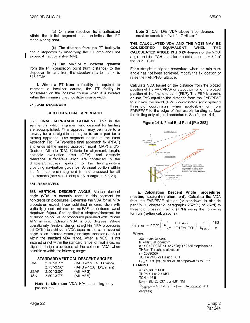
(1) For straight-in aligned procedures ONLY, when no other option is practical, calculate a VDA from each stepdown fix altitude above the vertical path (apply Vol. 1, chapter 2, para-graph 252a). Publish the greatest VDA and associate it with the applicable stepdown fix. See figure 14-6.
(2) For circling aligned procedures, when no other option is practical, calculate a VDA from each stepdown fix altitude above the vertical path (apply paragraph 252b) and ensure each angle is less than or equal to the maximum angle.
Figure 14-6. VDA with Stepdown Fixes [Par 252c].
2,600’
46’
1012’ MSL
FAF/PFAF 3.00°
29,420.54’
Stepdown#1below ∠
2,200’
23,344.42’
Stepdown#2
17,268.31’
2,080’
∠3.39°
(3) DO NOT raise stepdown fix altitudes
higher than needed for obstacle clearance solely to achieve coincidence with the VDA vertical path (USN N/A).
4) DO NOT establish maximum, mandatory, or mandatory block altitudes at any final segment fix except where operationally required and approved by AFS-400. Flight Standards approval will include a check of the final sub-segment descent rates and will specify necessary restrictions (e.g. do not publish VDA, etc.).
d. Stepdown Fixes (no-FAF procedures). Apply Vol. 1, chapter 2, paragraph 252a or 252b to calculate the VDA from the stepdown fix. When there are multiple stepdown fixes, also apply Vol. 1, chapter 2, paragraph 252c, except the vertical path is calculated from the first stepdown fix (farthest from RWT coordinates) instead of from the FAF/PFAF.
253. VISUAL DESCENT POINT (VDP). The VDP defines a point on an NPA procedure from which normal descent from the MDA may be commenced provided the required visual references have been acquired. ESTABLISH A VDP FOR ALL STRAIGHT-IN NPA PROCEDURES (to include those combined with a PA/APV procedure), with the following exceptions/limitations:
• Do not publish a VDP when the primary altimeter setting comes from a remote source.
• Do not publish a VDP located prior to a stepdown fix.
• If the VDP is between the MAP and the runway, do not publish a VDP.
• Do not publish a VDP when the 20:1 surface is penetrated (Vol. 1, chapter 3, paragraph 3.3.2d).
• When feasible, the VDP should be ≥ 1 NM from any other final segment fix (e.g., MAP, stepdown). When not feasible, the VDP must be at least 0.5 NM from any other final segment fix. If < 0.5 NM and the other fix cannot be relocated, do not publish a VDP. DO NOT increase the MDA to achieve the
• ≥ 0.5 NM distance.
a. Determine VDP distance. When dual or multiple lines of NPA minimums are published, use the lowest minimum descent altitude (MDA) from any CAT to calculate the VDP distance. Use the following formula to determine VDP distance from RWT coordinates (radian calculations):
( )⎛ ⎞⎛ ⎞π⎛ ⎞θ ⋅ ⋅ + +⎜ ⎟⎜ ⎟⎜ ⎟π π ⎝ ⎠⎜ ⎟⎜ ⎟= ⋅ − θ ⋅ −⎜ ⎟⎜ ⎟+⎜ ⎟⎜ ⎟
⎝ ⎠⎝ ⎠
VDP
cos r THRe TCH180D r asin
2 180 r MDA
Where:
MDA = Lowest Minimum Descent Altitude THRe = Threshold elevation TCH = VGSI or Design TCH r = 20890537 θ = VGSI or specified VDA
(1) For runways served by a VGSI (regardless of coincidence with final VDA) , using the VGSI TCH, establish the distance from RWT coordinates to a point where the lowest published VGSI glidepath angle reaches the appropriate MDA.
(2) For runways NOT served by a VGSI, using an appropriate TCH from Vol. 3, chapter 2, table 2-3, establish the distance from RWT coordinates to a point where the greater of a three degree or the final segment VDA reaches the appropriate MDA.
b. Marking VDP Location.
(1) For Non-RNAV Standard Instrument Approach Procedures (SIAPs), mark the VDP location with a DME fix. The DME source must be the same as for other DME fixes in the final segment. If DME is not available, do not establish a VDP. Maximum fix error is ± 0.5 NM.

6/5/09 8260.3B CHG 21
Page 24 Chap 2 Par 252
(2) For RNAV SIAPs, mark the VDP location with an along track distance (ATD) fix to the MAP. Maximum fix error is ± 0.5 NM.
(3) If the final course is not aligned with the runway centerline, use the RWT coordinates as a vertex, swing an arc of a radius equal to the VDP distance across the final approach course (see figure 14-7). The point of intersection is the VDP. (For RNAV procedures, the distance from the point of intersection to the MAP is the ATD for the VDP.)
Figure 14-7. VDP Location [Par 253b(3)].
VDP
Runway centerline and Final Approach Course
VDP distance from threshold
Arc Origin is the center of the threshold
Runway Centerline
VDP marked as ATD to MAP if RNAV.
Final Approach Course
VDP at the Intersection of arc and final course
VDP Distance
254.-259. RESERVED.
SECTION 6. CIRCLING APPROACH
260. CIRCLING APPROACH AREA. Where circling is authorized, evaluate the circling approach area for each CAT published on the procedure. The circling minimum descent altitude (CMDA) is based on the results of the circling area evaluation and the evaluation of the final segment delivering the aircraft to the circling area. Also see Vol. 1, chapter 3, paragraph 3.2.1b.
a. Obstacle Evaluation Area (OEA). The area for each CAT is based on true airspeed (VKTAS). The minimum altitude used for true airspeed conversion is 1,000 ft above airport elevation.
Use the following formula for converting indicated airspeed (VKIAS) to true airspeed (VKTAS) is:
( )( )⋅ ⋅ + ⋅ +
=⋅
2 628
KIAS
KTAS
V 171233 (288 15)-0.00198 )V
288 - 0.00198 alt+k.
( alt k
Where:
VKIAS = indicated airspeed (from table 4) alt = airport elevation (MSL) k = height above airport (1,000 ft minimum)
Calculate the Circling Approach Radius (CAR) based on true airspeed, bank angle, and straight segment length using the following formula (radian calculations):
( )+= +
π⋅ ⋅
225
2
68625 4180
KTAS
angle
V*CAR S
banktan( ) .
Where:
VKTAS = true airspeed bankangle = bank angle (from table 4) S = straight segment (from table 4)
*Minimum CAR = 1.30 NM
Table 4. Circling Approach Area Parameters [Par 260a].
CAT VKIAS Bankangle Straight
Segment Length (S)
A 90 25 0.4 B 120 25 0.4 C 140 20 0.5 D 165 20 0.6 E 200 22 0.7
The OEA is constructed by drawing arcs equal to the CAR for each CAT from the RWT coordinates (or displaced threshold coordinates when applicable) of each runway. Not applicable to permanently closed or other runways not authorized for circling. However, when only one end of the runway is not authorized for circling, the OEA is based on the CAR from both sets of RWT coordinates. Join the outermost arcs with tangential lines. The resulting enclosed area is the circling obstacle evaluation area (OEA) [no secondary area]. See figure 15-1.
b. Obstacle Clearance. Provide 300 ft ROC plus adjustments over the highest obstacle in the OEA.
Figure 15-1. Circling Approach OEA [Par 260a].

6/5/09 8260.3B CHG 21
Page 24 Chap 2 Par 252
c. CMDA. The published circling minimum descent altitude (CMDA) may not result in a height above airport (HAA) lower than permitted by Vol. 1, chapter 3, table 3-9.
Where the CMDA results in a HAA greater than 1,000 ft, re-calculate CAR by increasing k to equal the actual HAA and re-evaluate the OEA. If the resulting HAA value increases, re-calculate and re-evaluate using the higher value.
Example
CAT A controlling obstacle = 623 ft Airport Elevation = 600 ft CAT A minimum HAA (Vol. 1, chap 3) = 350 ft ROC = 300 CMDA based on ROC 623 + 300 = 923 (rounds to 940 ft) CMDA based on min HAA 600 + 350 = 950 ft (rounds to 960 ft) Published CMDA = 960 ft
261. RESTRICTED CIRCLING AREA. The circling OEA may be modified to gain relief from obstacles by establishing a restricted area. This option is only authorized where the restriction can clearly be described as a portion of the airspace where circling is not authorized and the chart is properly annotated. The OEA excludes the restricted area except the portion defined by a line originating at the RWT coordinates (or displaced threshold coordinates when applicable) of each runway used to define the area splaying 10 degrees relative to runway centerline towards the restricted area. Discontinue the splay when it reaches 4,500 ft in width from runway centerline extended (see figure 15-2a).
a. Simple restricted area. Establish the restricted area as the right or left half of the OEA relative to runway centerline(s) extended to the CAR boundary. The chart annotation must include the runway identification (both ends) and the area’s magnetic direction from runway centerline described as a cardinal/inter-cardinal compass direction (N, NE, E, SE, S, SW, W, NW). See Vol. 1, chapter 2, figures 15-2a through 15-2f and Order 8260.19, chapter 8.
Figure 15-2a. Restricted Circling Area (Simple) [Par 261a].
b. Complex restricted area. Establish the restricted area as a single contiguous sector bounded by the centerlines of intersecting runways (or runways extended) continued outward to the OEA boundary, truncated (figures 15-2b through 15-2d) or expanded (figure 15-2f) by a direct line from each set of RWT coordinates (or displaced threshold coordinates when applicable). The chart annotation includes the runway number and the general orientation of the restricted area from each runway described as a cardinal/inter-cardinal compass direction. See Vol. 1, chapter 2, figures 15-2b through 15-2g and Order 8260.19, chapter 8.
Figure 15-2b. Restricted Circling Area (Complex <180°) [Par 261b].
Figure 15-2c. Restricted Circling Area, Circling Aligned
(Complex <180°) [Par 261b].
Example: “Circling NA W of RWY 15 and NW of RWY6”
· 584
Approach direction
OEA
· 603 · 584
Example: “Circling NA NW of RWY 6-24”
Buffer areas splay 10° from RWT coordinates Approac
h
Splay stops at 4,500’
OEA
Example: “Circling NA W of RWY 15 and NW of RWY 6”
· 584
Approachdirection
OEA
Splay stops at 4,500’

6/5/09 8260.3B CHG 21
Chap 2 Page 26-1 Par 261
Figure 15-2d. Restricted Circling Area (Complex < 180°, Intersecting runways)
[Par 261b].
Figure 15-2e. Restricted Circling Area (Complex < 180°, Parallel runways)
[Par 261b].
Figure 15-2f. Restricted Circling Area (Complex > 180°) [Par 261b].
262.-269. RESERVED.
SECTION 7. MISSED APPROACH.
270. MISSED APPROACH SEGMENT. A missed approach procedure shall be established for each instrument approach procedure (IAP). The missed approach shall be initiated at the decision altitude (DA) or MAP in nonprecision approaches. The missed approach procedure must be simple, specify a charted missed approach altitude (altitude at clearance limit), and a clearance limit fix/facility. When required by obstacles or deemed operationally advantageous, the missed approach may also specify an interim “climb-to” altitude to identify a turn point. The charted missed approach altitude must not be lower than the highest DA/MDA (including adjustments) and be sufficient to permit holding or en route flight. Design alternate missed approach procedures using the criteria in this section. The area considered for obstacles has a width equal to that of the final approach area at the MAP or DA point and expands uniformly to the width of the initial approach
(Continued on Page 27)
· 603
· 584
· 728
Example: “Circling NA NW of RWY 24 and SW of 33”
Approachdirection
OEA
Example: “Circling NA SE of RWYs 27 and 36C”
Approach direction
· 1064
OEA
Example: “Circling NA N of · Appr
h
OEA

8260.3B CHG 21 6/5/09
Page 26-2 Chap 2 Par 270
THIS PAGE INTENTIONALLY LEFT BLANK
6/05/09 8260.3B CHG 21
Page 3-21
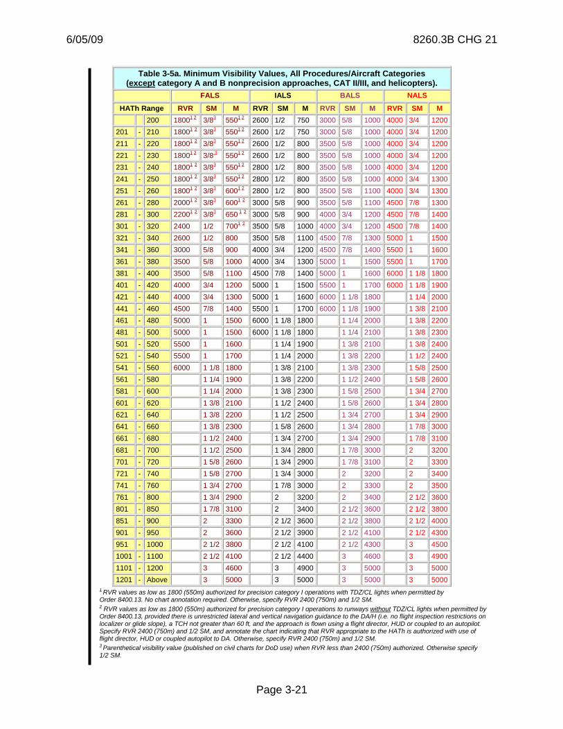
Table 3-5a. Minimum Visibility Values, All Procedures/Aircraft Categories (except category A and B nonprecision approaches, CAT II/III, and helicopters).
FALS IALS BALS NALS
HATh Range RVR SM M RVR SM M RVR SM M RVR SM M 200 18001 2 3/83 5501 2 2600 1/2 750 3000 5/8 1000 4000 3/4 1200 201 - 210 18001 2 3/83 5501 2 2600 1/2 750 3000 5/8 1000 4000 3/4 1200 211 - 220 18001 2 3/83 5501 2 2600 1/2 800 3500 5/8 1000 4000 3/4 1200 221 - 230 18001 2 3/8,3 5501 2 2600 1/2 800 3500 5/8 1000 4000 3/4 1200 231 - 240 18001 2 3/83 5501 2 2800 1/2 800 3500 5/8 1000 4000 3/4 1200 241 - 250 18001 2 3/83 5501 2 2800 1/2 800 3500 5/8 1000 4000 3/4 1300 251 - 260 18001 2 3/83 6001 2 2800 1/2 800 3500 5/8 1100 4000 3/4 1300 261 - 280 20001 2 3/83 6001 2 3000 5/8 900 3500 5/8 1100 4500 7/8 1300 281 - 300 22001 2 3/83 650 1 2 3000 5/8 900 4000 3/4 1200 4500 7/8 1400 301 - 320 2400 1/2 7001 2 3500 5/8 1000 4000 3/4 1200 4500 7/8 1400 321 - 340 2600 1/2 800 3500 5/8 1100 4500 7/8 1300 5000 1 1500 341 - 360 3000 5/8 900 4000 3/4 1200 4500 7/8 1400 5500 1 1600 361 - 380 3500 5/8 1000 4000 3/4 1300 5000 1 1500 5500 1 1700 381 - 400 3500 5/8 1100 4500 7/8 1400 5000 1 1600 6000 1 1/8 1800 401 - 420 4000 3/4 1200 5000 1 1500 5500 1 1700 6000 1 1/8 1900 421 - 440 4000 3/4 1300 5000 1 1600 6000 1 1/8 1800 1 1/4 2000 441 - 460 4500 7/8 1400 5500 1 1700 6000 1 1/8 1900 1 3/8 2100 461 - 480 5000 1 1500 6000 1 1/8 1800 1 1/4 2000 1 3/8 2200 481 - 500 5000 1 1500 6000 1 1/8 1800 1 1/4 2100 1 3/8 2300 501 - 520 5500 1 1600 1 1/4 1900 1 3/8 2100 1 3/8 2400 521 - 540 5500 1 1700 1 1/4 2000 1 3/8 2200 1 1/2 2400 541 - 560 6000 1 1/8 1800 1 3/8 2100 1 3/8 2300 1 5/8 2500 561 - 580 1 1/4 1900 1 3/8 2200 1 1/2 2400 1 5/8 2600 581 - 600 1 1/4 2000 1 3/8 2300 1 5/8 2500 1 3/4 2700 601 - 620 1 3/8 2100 1 1/2 2400 1 5/8 2600 1 3/4 2800 621 - 640 1 3/8 2200 1 1/2 2500 1 3/4 2700 1 3/4 2900 641 - 660 1 3/8 2300 1 5/8 2600 1 3/4 2800 1 7/8 3000 661 - 680 1 1/2 2400 1 3/4 2700 1 3/4 2900 1 7/8 3100 681 - 700 1 1/2 2500 1 3/4 2800 1 7/8 3000 2 3200 701 - 720 1 5/8 2600 1 3/4 2900 1 7/8 3100 2 3300 721 - 740 1 5/8 2700 1 3/4 3000 2 3200 2 3400 741 - 760 1 3/4 2700 1 7/8 3000 2 3300 2 3500 761 - 800 1 3/4 2900 2 3200 2 3400 2 1/2 3600 801 - 850 1 7/8 3100 2 3400 2 1/2 3600 2 1/2 3800 851 - 900 2 3300 2 1/2 3600 2 1/2 3800 2 1/2 4000 901 - 950 2 3600 2 1/2 3900 2 1/2 4100 2 1/2 4300 951 - 1000 2 1/2 3800 2 1/2 4100 2 1/2 4300 3 4500 1001 - 1100 2 1/2 4100 2 1/2 4400 3 4600 3 4900 1101 - 1200 3 4600 3 4900 3 5000 3 5000 1201 - Above 3 5000 3 5000 3 5000 3 5000
1 RVR values as low as 1800 (550m) authorized for precision category I operations with TDZ/CL lights when permitted by Order 8400.13. No chart annotation required. Otherwise, specify RVR 2400 (750m) and 1/2 SM. 2 RVR values as low as 1800 (550m) authorized for precision category I operations to runways without TDZ/CL lights when permitted by Order 8400.13, provided there is unrestricted lateral and vertical navigation guidance to the DA/H (i.e. no flight inspection restrictions on localizer or glide slope), a TCH not greater than 60 ft, and the approach is flown using a flight director, HUD or coupled to an autopilot. Specify RVR 2400 (750m) and 1/2 SM, and annotate the chart indicating that RVR appropriate to the HATh is authorized with use of flight director, HUD or coupled autopilot to DA. Otherwise, specify RVR 2400 (750m) and 1/2 SM. 3 Parenthetical visibility value (published on civil charts for DoD use) when RVR less than 2400 (750m) authorized. Otherwise specify 1/2 SM.
12/07/07 8260.3B CHG 20
Page 3-22
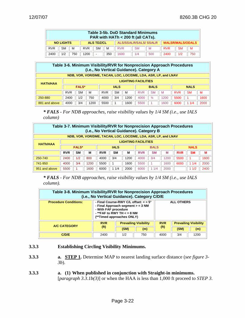
Table 3-5b. DoD Standard Minimums PAR with HATh < 200 ft (all CATs).
NO LIGHTS ALS TDZ/CL ALS/SSALR/SALS/ SSALR MALSR/MALS/ODALS
RVR SM M RVR SM M RVR SM M RVR SM M
2400 1/2 750 1200 - 350 1600 1/4 500 2400 1/2 750
Table 3-6. Minimum Visibility/RVR for Nonprecision Approach Procedures (i.e., No Vertical Guidance). Category A
NDB, VOR, VOR/DME, TACAN, LOC, LOC/DME, LDA, ASR, LP, and LNAV
LIGHTING FACILITIES HATh/HAA
FALS* IALS BALS NALS
RVR SM M RVR SM M RVR SM M RVR SM M 250-880 2400 1/2 750 4000 3/4 1200 4000 ¾ 1200 5500 1 1600 881 and above 4000 3/4 1200 5500 1 1600 5500 1 1600 6000 1 1/4 2000
* FALS - For NDB approaches, raise visibility values by 1/4 SM (i.e., use IALS column)
Table 3-7. Minimum Visibility/RVR for Nonprecision Approach Procedures (i.e., No Vertical Guidance). Category B
NDB, VOR, VOR/DME, TACAN, LOC, LOC/DME, LDA, ASR, LP, and LNAV LIGHTING FACILITIES
HATh/HAA FALS* IALS BALS NALS
RVR SM M RVR SM M RVR SM M RVR SM M 250-740 2400 1/2 800 4000 3/4 1200 4000 3/4 1200 5500 1 1600 741-950 4000 3/4 1200 5500 1 1600 5500 1 1600 6000 1 1/4 2000 951 and above 5500 1 1600 6000 1 1/4 2000 6000 1 1/4 2000 1 1/2 2400
* FALS - For NDB approaches, raise visibility values by 1/4 SM (i.e., use IALS column).
Table 3-8. Minimum Visibility/RVR for Nonprecision Approach Procedures (i.e., No Vertical Guidance). Category C/D/E
Procedure Conditions: - Final Course-RWY C/L offset: < = 5° - Final Approach segment > = 3 NM - With FAF procedure - **FAF to RWY TH < = 8 NM (**Timed approaches ONLY)
ALL OTHERS
Prevailing Visibility Prevailing Visibility A/C CATEGORY
RVR (ft) (SM) (m)
RVR (ft) (SM) (m)
C/D/E 2400 1/2 750 4000 3/4 1200
3.3.3 Establishing Circling Visibility Minimums.
3.3.3 a. STEP 1. Determine MAP to nearest landing surface distance (see figure 3-3b).
3.3.3 a. (1) When published in conjunction with Straight-in minimums. [paragraph 3.3.1b(3)] or when the HAA is less than 1,000 ft proceed to STEP 3.

6/5/09 8260.3B CHG 21
CHAPTER 10. RADAR APPROACH PROCEDURES AND VECTORING CHARTS
Section 1. General Information.
10.0 General. This chapter applies to radar approach procedures and vectoring charts utilizing ground-based radar or other approved surveillance systems (i.e., satellite-based). The types of systems supported are:
10.0.1 Precision Approach Radar (PAR) is a system that graphically displays lateral course, glidepath, and distance from touchdown information of sufficient accuracy, continuity, and integrity to provide precision approach capability to a runway/landing area.
10.0.2 Surveillance Radar is a system that displays direction and distance information with suitable accuracy, continuity, and integrity to safely provide radar vectoring capability for departures, arrivals, en route operations, and nonprecision approach (NPA) airport surveillance radar (ASR) approaches to an airport. For the purpose of these criteria, the minimum lateral clearance between aircraft and obstacles are:
10.0.2 a. Single Sensor describes adaptations based on the input of a single radar site and includes single sensor long-range radar mode. May apply to the entire radar display or within a defined area on the radar display.
• When the aircraft is less than *40 nautical miles (NM) from the antenna, minimum lateral clearance is 3 NM.
• When the aircraft is *40 NM or more from the antenna, minimum lateral clearance is 5 NM.
Note: 60 NM for approved full time reinforced monopulse secondary surveillance Radar (MSSR) systems.
10.0.2. b. Multi Sensor describes adaptations based on the input of multiple radar sites and includes Mosaic Mode, Multi-Sensor Mode, Stage A/DARC, Fusion Mode, and Center Radar ARTS Presentation (CENRAP). May apply to the entire radar display or within a defined area of a radar display.
Note: Minimum lateral clearance is 5 NM.
10.0.3 Automatic Dependent Surveillance - Broadcast (ADS-B) [TBD].
Vol. 1 Page 10-1 UNCONTROLLED COPY WHEN DOWNLOADED
Check with FSIMS to verify current version before using

6/5/09 8260.3B CHG 21
CHAPTER 10. RADAR APPROACH PROCEDURES AND VECTORING CHARTS
Section 2. Radar Approaches.
10.1. Radar Approaches. Both ASR and PAR approach procedures may be established where the applicable Order 8200.1, U. S. Standard Flight Inspection Manual coverage, and alignment tolerances are met. ASR approaches may be established when the final segment is adapted for single sensor operations and the radar antenna is not more than 20 NM from;
• The approach runway threshold (RWT) coordinates when the procedure is designed to meet straight-in alignment.
• The airport reference point (ARP) when the procedure is designed to meet circling-only alignment.
10.1.1 Feeder Routes and Initial Approach Segments. Feeder and initial segments do not need to be established when navigation guidance and obstacle clearance are provided by Air Traffic Control radar vectors during the transition from the en route to the terminal phase of flight.
10.1.1 a. Feeder/Initial Segments based on Routes [Department of Defense (DoD) Only]. When operationally required, establish feeder routes and/or initial segments based on conventional navigation, area navigation (RNAV), or radar routes.
10.1.1 a. (1) Conventional/RNAV Feeder/Initial. Develop in accordance with TERPS Volume 1, chapter 2 or Order 8260.54, United States Standard for Area Navigation (RNAV), chapter 2.
10.1.1 a. (2) Radar Feeder/Initial. The route/segment begins at an established fix that permits positive radar identification and ends at the appropriate termination fix for the segment. Display the course centerline on a radar video map (e.g., as a “special use” track per Order 7210.3, Facility Operation and Administration, chapter 3, section 8 or DoD equivalent).
10.1.1 a. (2) (a) Alignment. Design feeder/initial and initial/initial segment intersections with the smallest amount of course change necessary for the procedure. The maximum allowable course change between segments is 90 degrees.
10.1.1 a. (2) (b) Area. The obstacle evaluation area (OEA) begins at the applicable radar fix displacement prior to the route/segment start fix and extends to the segment termination fix. Primary area half-width is equal to the minimum lateral clearance applicable to the radar adaptation (TERPS, Vol. 1, chapter 10, paragraph 10.0.2) from course centerline. There is no secondary area. The area has no specified maximum or minimum length; however, the segment must be long enough to permit the required altitude loss without exceeding the maximum authorized descent gradient.
Vol. 1 Page 10-2 UNCONTROLLED COPY WHEN DOWNLOADED
Check with FSIMS to verify current version before using

6/5/09 8260.3B CHG 21
Note: When the minimum lateral clearance changes within a segment (e.g. when transitioning from a multi- to single-sensor adaptation, or at the applicable distance for a single-sensor adaptation), the OEA half-width also changes without the need to “splay” or “taper.”
10.1.1 a. (2) (c) Obstacle Clearance. Apply the TERPS Volume 1, chapter 2 standard applicable to the segment. TERPS Volume 1, chapter 3 precipitous terrain adjustments apply
10.1.1 a. (2) (d) Descent Angle. Apply TERPS Volume 1, chapter 2 standard applicable to the segment.
10.1.1 a. (2) (e) Altitude Selection. Apply TERPS Volume 1, chapter 2 standard applicable to the segment. Do not publish fix altitudes higher than the minimum required for obstacle clearance or airspace to achieve an “optimum” descent gradient.
10.1.2 Intermediate Approach Segment. Establish an intermediate segment when necessary (e.g., ATC radar vectors not available or MVA too high to support desired FAF/PFAF altitude). The intermediate segment begins at the intermediate fix and extends to the PFAF. When there is a preceding conventional /RNAV route segment, the applicable conventional/RNAV intermediate segment standards apply, except as specified in TERPS, Vo. 1, chapter 10, paragraph 10.1.2b(2).
10.1.2 a. Alignment. The intermediate course is an extension of the final approach course (no course change permitted at the PFAF).
10.1.2 b. Area.
10.1.2 b. (1) Radar Intermediate. When radar is used for course guidance (route or vector), the OEA begins at the applicable radar fix displacement prior to the intermediate fix (IF) and extends to the PFAF. Primary area half-width is equal to the minimum lateral clearance applicable to the radar adaptation (TERPS, Volume1, chapter 10, paragraph 10.0.2) until reaching a point 2 NM prior to the PFAF, then tapers to the width of the ASR/PAR/PAR without glideslope final approach segment (FAS) primary OEA width abeam the PFAF (TERPS, Volume 1, chapter 10, paragraph 10.1.4 and TERPS, Volume 3, chapter 3, paragraph 3.0) (USN NA). There are no intermediate secondary areas. See figure 10-1.
Note: When the minimum lateral clearance changes within a segment (e.g. when transitioning from a multi- to single-sensor adaptation, or at the applicable distance for a single-sensor adaptation), the OEA half-width also changes without the need to “splay” or “taper.”
10.1.2 b. (2) Non-Radar Intermediate. When conventional/RNAV navigation is used for course guidance, apply the intermediate OEA criteria from the applicable 8260-series order with the following exceptions:
Vol. 1 Page 10-3 UNCONTROLLED COPY WHEN DOWNLOADED
Check with FSIMS to verify current version before using
6/5/09 8260.3B CHG 21
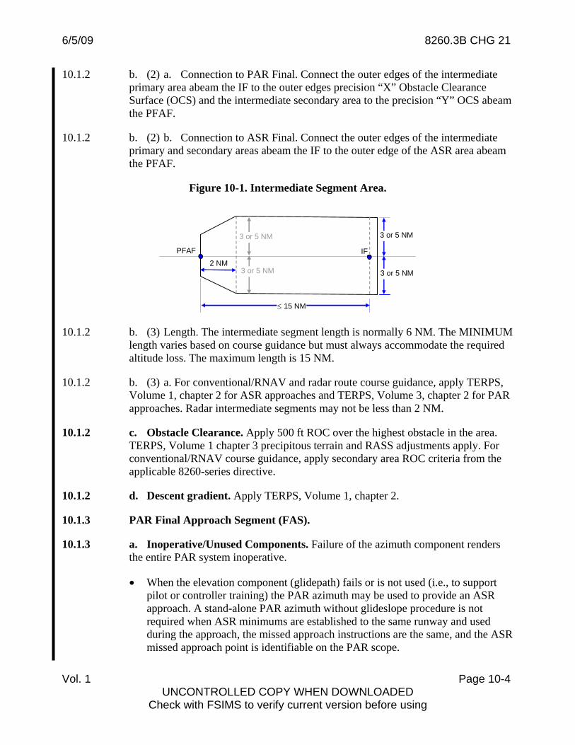
10.1.2 b. (2) a. Connection to PAR Final. Connect the outer edges of the intermediate primary area abeam the IF to the outer edges precision “X” Obstacle Clearance Surface (OCS) and the intermediate secondary area to the precision “Y” OCS abeam the PFAF.
10.1.2 b. (2) b. Connection to ASR Final. Connect the outer edges of the intermediate primary and secondary areas abeam the IF to the outer edge of the ASR area abeam the PFAF.
Figure 10-1. Intermediate Segment Area.
3 or 5 NM
3 or 5 NM
≤ 15 NM
PFAF
3 or 5 NM
3 or 5 NM
2 NM IF
10.1.2 b. (3) Length. The intermediate segment length is normally 6 NM. The MINIMUM length varies based on course guidance but must always accommodate the required altitude loss. The maximum length is 15 NM.
10.1.2 b. (3) a. For conventional/RNAV and radar route course guidance, apply TERPS, Volume 1, chapter 2 for ASR approaches and TERPS, Volume 3, chapter 2 for PAR approaches. Radar intermediate segments may not be less than 2 NM.
10.1.2 c. Obstacle Clearance. Apply 500 ft ROC over the highest obstacle in the area. TERPS, Volume 1 chapter 3 precipitous terrain and RASS adjustments apply. For conventional/RNAV course guidance, apply secondary area ROC criteria from the applicable 8260-series directive.
10.1.2 d. Descent gradient. Apply TERPS, Volume 1, chapter 2.
10.1.3 PAR Final Approach Segment (FAS).
10.1.3 a. Inoperative/Unused Components. Failure of the azimuth component renders the entire PAR system inoperative.
• When the elevation component (glidepath) fails or is not used (i.e., to support pilot or controller training) the PAR azimuth may be used to provide an ASR approach. A stand-alone PAR azimuth without glideslope procedure is not required when ASR minimums are established to the same runway and used during the approach, the missed approach instructions are the same, and the ASR missed approach point is identifiable on the PAR scope.
Vol. 1 Page 10-4 UNCONTROLLED COPY WHEN DOWNLOADED
Check with FSIMS to verify current version before using

6/5/09 8260.3B CHG 21
• Alternatively, a separate PAR azimuth without glideslope procedure may be established when required and/or operationally advantageous, Evaluate using the localizer area and obstacle clearance requirements specified in TERPS, Volume 1, chapter 9. NPA minimums are established according to TERPS, Volume 1, chapter 3, section 3 and documented in accordance with applicable directives.
10.1.3 b. General. Apply the current basic vertically guided final segment general criteria applicable to instrument landing system (ILS) for glidepath angle (GPA), threshold crossing height (TCH), precise final approach fix (PFAF), glidepath qualification surface (GQS), and precision obstacle free zone (POFZ).
10.1.3 b. (1) Use the highest applicable MVA to determine the PFAF distance to LTP/coordinates when there is no preceding segment.
10.1.3 b. (2) ILS height above touchdown/threshold (HAT/HATh) and decision altitude (DA) standards apply (to include TERPS Volume 1, chapter 3 adjustments), except the minimum HAT/HATh may be 100 ft for DoD-only approaches when the OCS is clear. Adjusting TCH to reduce/eliminate OCS penetrations is not applicable to PAR FAS evaluations.
10.1.3 c. Obstacle Evaluation Area (OEA)/Obstacle Clearance Surface (OCS). [USN: See applicable directives.] Apply current ILS FAS criteria for alignment, OCS slope, width, height, and OEA/OCS evaluation except the OEA extends to the PFAF (no radar fix tolerance applied). Also, where the PFAF must be located more than 50,200 ft from the RWT coordinates, the OEA continues to splay to the PFAF or until reaching the minimum lateral clearance applicable to the radar adaptation (TERPS, Volume 1, Chapter 10, paragraph 10.0.2).
10.1.3 d. Simultaneous PAR Procedures (DoD only). Where military authority determines facilities and equipment are adequate, PAR approach procedures to parallel runways may be established. See applicable DoD directives.
10.1.4 ASR Final Approach Segment (FAS). Use the highest applicable MVA to determine the PFAF location when there is no preceding segment.
10.1.4. a. General. Apply the current non-vertically guided final segment general criteria.
10.1.4. b. Alignment. Align the final approach course (FAC) with the extended runway centerline for a straight-in approach, or to the airport reference point for a circling approach. When an operational advantage can be achieved, the FAC for circling approaches may be aligned to pass through any portion of the usable landing surface.
Vol. 1 Page 10-5
10.1.4. c. Area. The final approach begins at the applicable radar fix displacement prior to the PFAF and ends at the RWT (straight-in)/FEP (circling) or the appropriate radar fix displacement beyond the missed approach point (MAP), whichever is encountered last.
UNCONTROLLED COPY WHEN DOWNLOADED Check with FSIMS to verify current version before using
6/5/09 8260.3B CHG 21
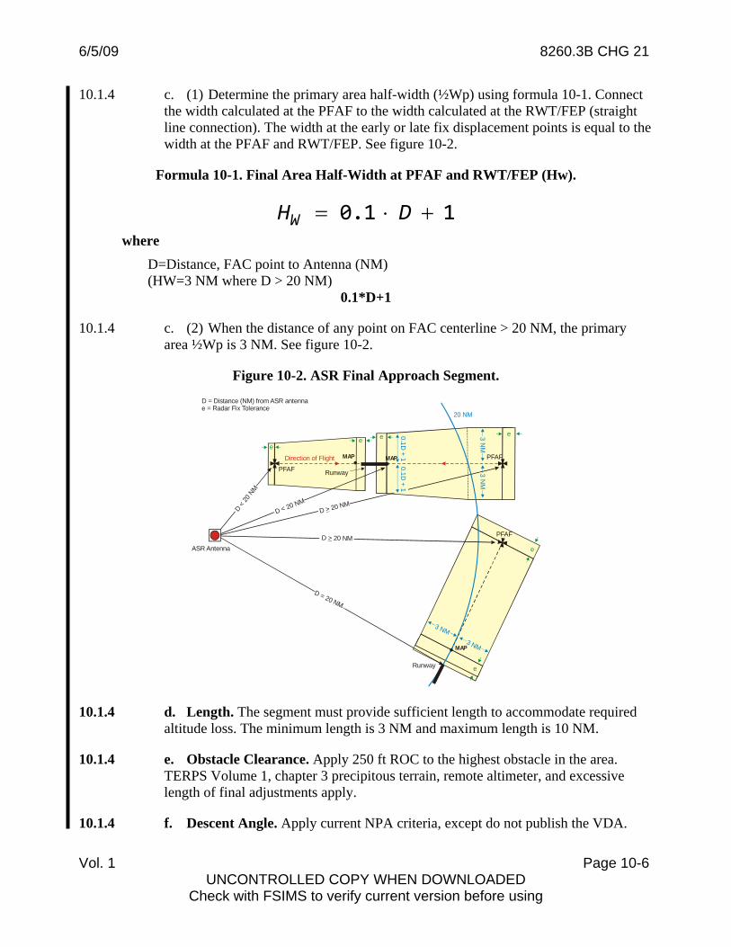
10.1.4 c. (1) Determine the primary area half-width (½Wp) using formula 10-1. Connect the width calculated at the PFAF to the width calculated at the RWT/FEP (straight line connection). The width at the early or late fix displacement points is equal to the width at the PFAF and RWT/FEP. See figure 10-2.
Formula 10-1. Final Area Half-Width at PFAF and RWT/FEP (Hw).
0.1 1= ⋅ +WH D where
D=Distance, FAC point to Antenna (NM) (HW=3 NM where D > 20 NM)
0.1*D+1
10.1.4 c. (2) When the distance of any point on FAC centerline > 20 NM, the primary area ½Wp is 3 NM. See figure 10-2.
Figure 10-2. ASR Final Approach Segment.
Runway
D = Distance (NM) from ASR antennae = Radar Fix Tolerance
Runway
PFAF
20 NM
Direction of Flight
0.1D + 1
3 NM
3 NM
3 NM
3 NM
0.1D + 1
D = 20 NM
e
eeee
PFAFD 20 NM>ASR Antenna e
D 20 NM>D < 20 NM
D < 20
NM
PFAF
MAP MAP
MAP
10.1.4 d. Length. The segment must provide sufficient length to accommodate required altitude loss. The minimum length is 3 NM and maximum length is 10 NM.
10.1.4 e. Obstacle Clearance. Apply 250 ft ROC to the highest obstacle in the area. TERPS Volume 1, chapter 3 precipitous terrain, remote altimeter, and excessive length of final adjustments apply.
10.1.4 f. Descent Angle. Apply current NPA criteria, except do not publish the VDA.
Vol. 1 Page 10-6 UNCONTROLLED COPY WHEN DOWNLOADED
Check with FSIMS to verify current version before using

6/5/09 8260.3B CHG 21
10.1.4 g. Recommended Altitudes (RecAlt). Determine recommended altitudes at each mile on final approach for ATC use. Determine RecAlt values using formula 10-2.
Formula 10-2. Recommended Altitudes (RecAlt).
RecAlt A ‐ DG= where
A=PFAF altitude or last RecAlt (unrounded) DG=(1852/0.3048) x tan [VDA calculated per Vol. 1, Chap. 2, para. 252]
A-DG
RecAlt values below MDA are not issued. Round recommended altitudes to the nearest 20-ft increment. See the examples below.
Example:
PFAF altitude=2,000’, MDA=660’, VDA=3.00? (318.436/NM) 6 NM (PFAF)=2,000’ 5 NM recommended altitude: 2,000 - 318.436=1,681.564 (1,680) 4 NM recommended altitude: 1,681.564 - 318.436=1363.128 (1,360) 3 NM recommended altitude: 1,363.128 - 318.436=1,044.692 (1,040) 2 NM recommended altitude: 1,044.692 - 318.436=726.256 (720) 1 NM recommended altitude: 726.256 - 318.436=407.82 (Not issued)
10.1.4 h. RecAlt with Stepdown Fix above the VDA. When the minimum altitude at a stepdown fix is above the vertical path of the VDA, calculate RecAlt using the appropriate VDA for each subsegment (i.e., VDA from PFAF to stepdown altitude prior to stepdown fix, and VDA from stepdown altitude to TCH after the stepdown fix).
Example:
PFAF altitude=3,300’, MDA=1,400’, VDA PFAF to stepdown fix=3.00? (318.436/NM), VDA at 4 NM SDF to TCH=3.39? (359.924/NM) 6 NM (PFAF)=3,300 5 NM recommended altitude: 3,300 - 318.436=2,981.564 (2,980) 4 NM recommended altitude: 2,981.564 - 318.436=2,663.128 (2,660) 3 NM recommended altitude: 2,663.128 - 359.924=2,303.204 (2,300) 2 NM recommended altitude: 2,303.204 - 359.924=1,943.280 (1,940) 1 NM recommended altitude: 1,943.280 - 359.924=1,583.356 (1,580)
10.1.5 Missed Approach Segment (MAS).
Vol. 1 Page 10-7
10.1.5 a. PAR. Apply the current TERPS, Volume 3 Category (CAT) I ILS missed approach criteria to approaches with HAT/HATh values greater than or equal to 200 ft. Apply current CAT II ILS missed approach criteria for approaches with
UNCONTROLLED COPY WHEN DOWNLOADED Check with FSIMS to verify current version before using

6/5/09 8260.3B CHG 21
Vol. 1 Page 10-8 UNCONTROLLED COPY WHEN DOWNLOADED
Check with FSIMS to verify current version before using
HAT/HATh values lower than 200 ft, except USN approaches annotated “Not for Civil Use”.
10.1.5 b. ASR. Apply the current TERPS, Volume 1, chapter 2 NPA missed approach criteria. The MAP is located on the final approach course not farther from the PFAF than the FEP.
6/5/09 8260.3B CHG 21
CHAPTER 10. RADAR APPROACH PROCEDURES AND VECTORING CHARTS (MVAC)
Section 3. Minimum Vectoring Altitude Charts.
10.2 Minimum Vectoring Altitude Chart (MVAC). An MVAC is used by air traffic facilities when providing terminal service. An MVAC may be developed by En Route facilities in selected areas where the MIA chart does not meet operational needs. An MVAC specifies the lowest MSL altitude at or above the floor of controlled airspace that provides at least the minimum ROC over obstacles. The MVAC may be used in lieu of feeder, initial, and intermediate approach segment(s) for radar approaches.
Note: See Orders 7210.3, Facility Operations and Administration, 7210.37, En Route Minimum IFR Altitude (MIA) Sector Charts, or DoD directive.
10.2.1 General. Apply current Order 7210.3 criteria (or applicable DoD directive) to determine when an MVAC is required, the range/coverage of the chart(s) and the lateral obstacle clearance applicable to the chart and/or specific sectors. When the area of responsibility is beyond the radar system limits but a vectoring chart is still operationally necessary, apply Order 7210.37 for the non-radar area.
Note: The current vertical and horizontal obstacle accuracy standards in Order 8260.19 apply.
10.2.2 Single Sensor Adaptation. Center the MVAC on the radar sensor to facilitate distance measurements (e.g., to determine the minimum lateral clearance). Define sector boundaries by bearings, point-to-point lines, arcs, and/or circles relative to a specified point or points (e.g., radar antenna, NAVAID, fix, latitude/longitude coordinate, etc.). See figure 10-3.
Vol. 1 Page 10-9 UNCONTROLLED COPY WHEN DOWNLOADED
Check with FSIMS to verify current version before using

6/5/09 8260.3B CHG 21
Figure 10-3. MVAC for Single-Sensor Adaptation.
10.2.3 Multi-sensor Adaptation. Sector boundaries may be defined by any combination of bearings, point-to-point lines, arcs, and/or circles relative to a specified point or points (e.g., radar antenna, NAVAID, fix, latitude/longitude coordinate, etc.). See figure 10-4.
Figure 10-4. MVAC for Multi Sensor Adaptation.
113
113
100
100108
108
114
114
103
119
140
148 94
94
74
70
101
118118
118
*118148
133
10.2.4 Sectors. The MVAC may be subdivided into sectors to gain relief from obstacles. There is no prescribed limit on the size, shape, or orientation of MVAC sectors. Where small contiguous sectors with different altitudes do not serve an operational need, consider combining them.
Vol. 1 Page 10-10
10.2.4 a. Obstacle Evaluation Area. Adjacent sectors share common boundaries; however, each sector OEA is stand-alone and evaluated separately. The sector OEA includes the volume of airspace contained within its defined boundaries. Except for
UNCONTROLLED COPY WHEN DOWNLOADED Check with FSIMS to verify current version before using

6/5/09 8260.3B CHG 21
isolation areas (see TERPS, Volume 1, chapter 10, paragraph 10.2.4b), each sector includes a buffer equal to the minimum required lateral clearance for the applicable radar adaptation.
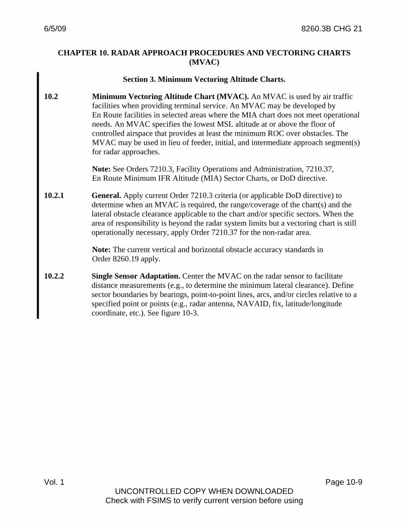
10.2.4 a. (1) Single Sensor. An OEA buffer expands outward at least 3 NM from those portions of the boundary within *40 NM of the radar antenna and at least 5 NM outward from those portions of the boundary equal to or greater than *40 NM from the radar antenna. When a contiguous sector crosses *40 NM from the radar antenna, the sector is effectively divided into sub-sectors at the *40 NM arc and normal OEA/buffers applied to each, except buffers expanding INTO the sector may be truncated at the boundary. The highest altitude from each sub-sector applies. See figures 10-5/5a.
*60 NM for approved full time reinforced MSSR systems.
Figure 10-5. Sector Buffer Areas (Single sensor, w/out reinforced MSSR)
Vol. 1 Page 10-11 UNCONTROLLED COPY WHEN DOWNLOADED
Check with FSIMS to verify current version before using
6/5/09 8260.3B CHG 21
Figure 10-5a. Buffer Area, Contiguous Sector crossing 40 NM. (Single sensor, w/out reinforced MSSR)
Vol. 1 Page 10-12
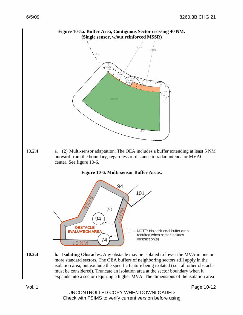
10.2.4 a. (2) Multi-sensor adaptation. The OEA includes a buffer extending at least 5 NM outward from the boundary, regardless of distance to radar antenna or MVAC center. See figure 10-6.
Figure 10-6. Multi-sensor Buffer Areas.
94
94
74
70
5 N
M
5 NM
OBSTACLEEVALUATION AREA
5 NM
101
NOTE: No additional buffer arearequired when sector isolates obstruction(s)
10.2.4 b. Isolating Obstacles. Any obstacle may be isolated to lower the MVA in one or more standard sectors. The OEA buffers of neighboring sectors still apply in the isolation area, but exclude the specific feature being isolated (i.e., all other obstacles must be considered). Truncate an isolation area at the sector boundary when it expands into a sector requiring a higher MVA. The dimensions of the isolation area
UNCONTROLLED COPY WHEN DOWNLOADED Check with FSIMS to verify current version before using

6/5/09 8260.3B CHG 21
otherwise depends on the feature type and whether single or multi-sensor adaptation applies.
10.2.4 b. (1) Point Feature (antennas, towers, high-rise buildings, etc). The isolation area is based on a radius centered on the feature that provides at least the minimum lateral clearance applicable to the radar adaptation (TERPS, Volume 1, chapter 10, paragraph 10.0.2). Order 8260.19 chapter 2, Section 11 applies. Isolation areas for multiple point features (i.e., antenna or wind farms) may be combined, however the minimum required lateral clearance must be provided from each feature and the MVA must equal the highest required for any individual feature.
10.2.4 b. (1) (a) Single-sensor adaptations. The isolation area boundary is a 3 NM radius when the feature is #35 NM or less from the radar antenna, and a 5 NM radius when the feature is more than #35 NM from the radar antenna. See figure 10-7. When operationally advantageous, the boundary may be reduced to less than 5 NM for those portions of the isolation area within *40 NM from the antenna, but not less than the minimum required lateral clearance. See Figure 10-7a.
#55 NM for approved full time reinforced MSSR systems. *60 NM for approved full time reinforced MSSR systems.
10.2.4 b. (1) (b) Multi-sensor adaptations. Isolation area boundary is a 5 NM radius, regardless of distance from radar antenna.
Figure 10-7. Isolation Area , Point Feature
41
42
29
24
35 or 55 NM from radar
5 NM
3 NM
3058
3125
(2063)
1386(300)
1195(270)
1335(335) 1377
(480)
(2060)
10.2.4 b. (2) Zone Feature (e.g., distinct terrain, topographical contours, etc.). When determining the sector boundary first define the dimensions of the feature to be isolated (e.g., mountain from 4,700 ft contour and above).
Vol. 1 Page 10-13 UNCONTROLLED COPY WHEN DOWNLOADED
Check with FSIMS to verify current version before using

6/5/09 8260.3B CHG 21
10.2.4 b. (2) (a) Single-sensor adaptations. Establish the isolation area boundary 3 NM from the feature for points 35 NM or less from the radar antenna, and 5 NM from the feature for points more than 35 NM from the radar antenna. When operationally advantageous, the boundary may be reduced to less than 5 NM for those portions of the isolation area within 40 NM from the antenna, but not less than the minimum required lateral clearance. See Figures 10-8 and 10-8a.
10.2.4 b. (2) (b) Multi-sensor adaptations. Isolation area boundary is a 5 NM from the feature, regardless of distance from radar antenna.
Figure 10-7a. Isolation Area, Point Feature, Example construction > 35 NM from Radar (Single sensor, w/out reinforced MSSR)
Vol. 1 Page 10-14
43 NM
44 NM
45 NM
41 NM
35.1 NM 36 NM 37.1 NM
See inset
Chord from intersect. w/ 40 NM radius
Inset
UNCONTROLLED COPY WHEN DOWNLOADED Check with FSIMS to verify current version before using

6/5/09 8260.3B CHG 21
Figure 10-8. Isolation Area, Zone Feature > 35 NM from Radar (Single sensor, w/out reinforced MSSR)
Figure 10-8a. Isolation Area, Zone Feature, Example construction > 35 NM (Single sensor, w/out reinforced MSSR)
10.2.5 Obstacle Clearance. Required obstacle clearance depends on the radar adaptation and the relationship of the obstacle to those areas designated mountainous per 14 CFR part 95 Subpart B.
67
70
67
Vol. 1 Page 10-15 UNCONTROLLED COPY WHEN DOWNLOADED
Check with FSIMS to verify current version before using
6/5/09 8260.3B CHG 21
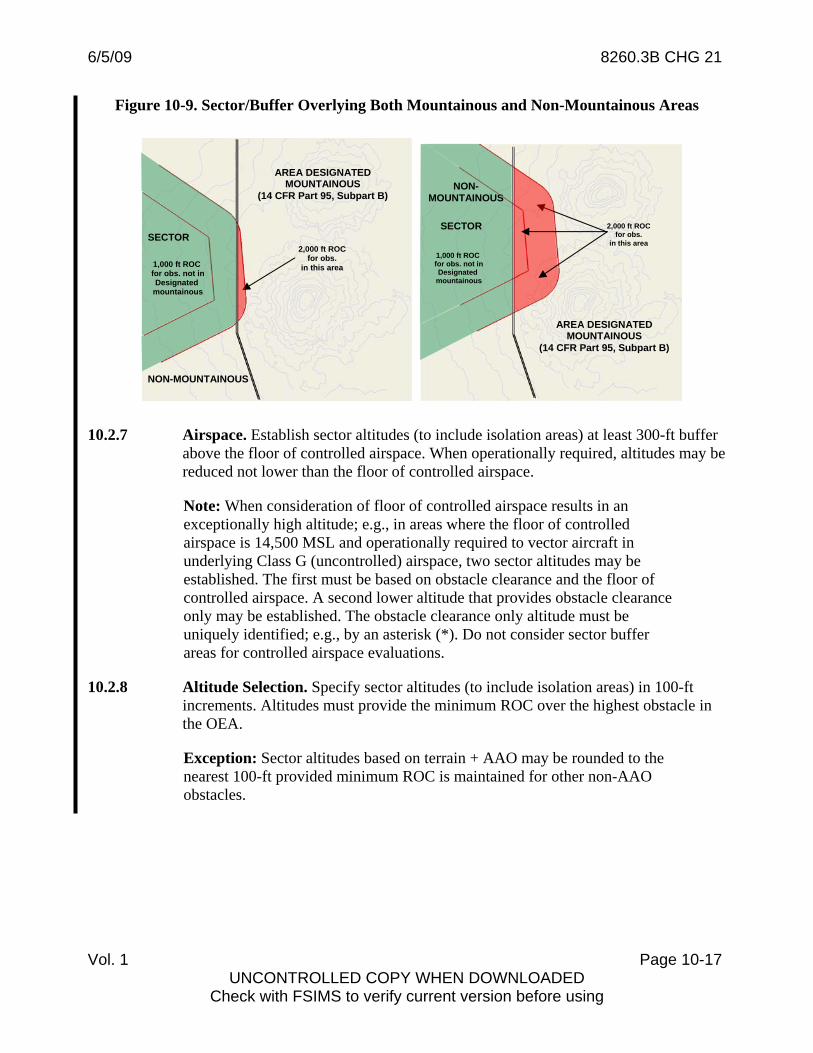
10.2.5 a. Non-Mountainous Terrain. Apply 1,000 ft ROC over obstacles in non-mountainous areas.
10.2.5 b. Mountainous Terrain. Apply 2,000 ft ROC over obstacles in designated mountainous areas. ROC may only be reduced when a reduction has been requested, approved, and documented in accordance with current Order 7210.3, ATC Facility Operation and Administration standards (to include associated Notices). Authorized ROC reductions are:
10.2.5 b. (1) Single sensor adaptation: Not less than 1,000 ft.
10.2.5 b. (2) Multi-sensor adaptation:
10.2.5 b. (2) a. Terrain. Not less than 1,500 ft (designated mountainous areas of the Eastern United States, Commonwealth of Puerto Rico, and Hawaii) or 1,700 ft (designated mountainous areas of the Western United States and Alaska).
10.2.5 b. (2) b. Man-made obstacles. Not less than 1,000 ft over the obstacle, but the MVA must also provide the minimum required 1,500/1,700 ROC over the terrain underlying the man-made structure.
10.2.5 c. When a sector/buffer/isolation area overlies both non-mountainous and mountainous terrain, consider revising sector boundaries. Otherwise, apply the appropriate ROC based on the location of the obstacle. See figure 10-9.
10.2.6 Adverse Assumption Obstacle (AAO) considerations.
10.2.6 a. Apply AAO to terrain except those areas around primary/satellite airports exempted by Order 8260.19 and/or when applying 2,000 unreduced ROC.
10.2.6 b. When an AAO is the controlling obstacle for a sector and an operational need is demonstrated/approved (e.g., altitude is necessary to support vectoring to the ILS glideslope), facilities are permitted to round the resulting altitude to the nearest 100 ft increment (i.e. 3,049 rounds to 3,000) providing the minimum ROC is maintained for other non-AAO obstacles.
Note: When an operational need has been demonstrated/approved it must be documented in the Form 7210-9, Remarks section.
Vol. 1 Page 10-16 UNCONTROLLED COPY WHEN DOWNLOADED
Check with FSIMS to verify current version before using
6/5/09 8260.3B CHG 21
Vol. 1 Page 10-17 UNCONTROLLED COPY WHEN DOWNLOADED
Check with FSIMS to verify current version before using
Figure 10-9. Sector/Buffer Overlying Both Mountainous and Non-Mountainous Areas
10.2.7 Airspace. Establish sector altitudes (to include isolation areas) at least 300-ft buffer
above the floor of controlled airspace. When operationally required, altitudes may be reduced not lower than the floor of controlled airspace.
Note: When consideration of floor of controlled airspace results in an exceptionally high altitude; e.g., in areas where the floor of controlled airspace is 14,500 MSL and operationally required to vector aircraft in underlying Class G (uncontrolled) airspace, two sector altitudes may be established. The first must be based on obstacle clearance and the floor of controlled airspace. A second lower altitude that provides obstacle clearance only may be established. The obstacle clearance only altitude must be uniquely identified; e.g., by an asterisk (*). Do not consider sector buffer areas for controlled airspace evaluations.
10.2.8 Altitude Selection. Specify sector altitudes (to include isolation areas) in 100-ft increments. Altitudes must provide the minimum ROC over the highest obstacle in the OEA.
Exception: Sector altitudes based on terrain + AAO may be rounded to the nearest 100-ft provided minimum ROC is maintained for other non-AAO obstacles.
AREA DESIGNATED MOUNTAINOUS
(14 CFR Part 95, Subpart B)
1,000 ft ROC for obs. not in
Designated mountainous
2,000 ft ROC SECTOR
NON-MOUNTAINOUS
2,000 ft ROC for obs.
in this area
AREA DESIGNATED MOUNTAINOUS
(14 CFR Part 95, Subpart B)
1,000 ft ROC for obs. not in
Designated mountainous
SECTOR
NON-MOUNTAINOUS
for obs. in this area

6/5/09 8260.3B CHG 21
Vol. 3 Page 2-11 Par 2.9
Where: A = PFAF Altitude in feet (example 2,100) F = THRe or LTP elevation in feet (example 562.30) θ = Glidepath angle (example 3.00 degrees)
2.9.1 Distance Measuring Equipment (DME). When installed with ILS, DME may be used in lieu of the outer marker. When a unique requirement exists, DME information derived from a separate facility, as specified in Vol. 1, chapter 2, paragraph 282, may also be used to provide ARC initial approaches, a PFAF for back course (BC) approaches, or as a substitute for the outer marker. When used as a substitute for the outer marker, the plotted position of the fix must be ≤ 16.66 NM from the DME facility and the angular divergence at the fix must not exceed 6 degrees (DoD 23 degrees).
Note: The restriction on angular divergence only applies to a DME fix used in lieu of OM for the precision approach. For localizer approaches not combined with an ILS, Vol. 1, chapter 2, paragraph 282a, applies.
2.10 COMMON FIXES [RNAV Only]. Design all procedures published on the same chart to use the same sequence of charted fixes.
2.11 GLIDEPATH QUALIFICATION SURFACE (GQS). The GQS extends from runway threshold along the runway centerline and extends to the DA point. It limits the height of obstacles between DA and runway threshold (RWT). When obstacles exceed the height of the GQS, an approach procedure with vertical guidance (ILS, PAR, MLS, TLS, LPV, Baro-VNAV, etc.) is not authorized.
Note: Obstacles excluded by paragraph 2.11.1d may penetrate the GQS without penalty. When other obstacles penetrate the GQS, vertically guided approach operations may be authorized when mitigated (e.g., approach restricted to Height Group 1 and 2 aircraft). Contact FAA Flight Procedure Standards Branch, AFS-420, (or appropriate military equivalent) for case-by-case analysis.
2.11.1 Area.
2.11.1 a. Origin and Length. The sloping qualification surface originates at either the RWT or a specified distance from RWT (XOFFSET). The surface origin height is either THRe or a specified height above THRe (VOFFSET). The value of VOFFSET and XOFFSET are dependent on the TCH and Glidepath angle (θ).
6/5/09 8260.3B CHG 21
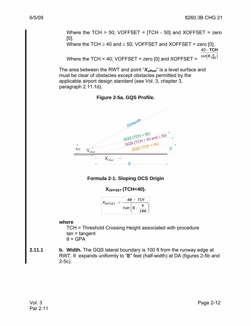
Vol. 3 Page 2-12 Par 2.11
Where the TCH > 50; VOFFSET = [TCH - 50] and XOFFSET = zero [0]. Where the TCH ≥ 40 and ≤ 50; VOFFSET and XOFFSET = zero [0].
Where the TCH < 40; VOFFSET = zero [0] and XOFFSET = ( )πθ−
180
40tan
TCH
The area between the RWT and point “Xoffset” is a level surface and must be clear of obstacles except obstacles permitted by the applicable airport design standard (see Vol. 3, chapter 3, paragraph 2.11.1d).
Figure 2-5a. GQS Profile.
Xoffset
Voffset
GQS (TCH > 50)
GQS (TCH < 40)GQS (TCH 40 and 50)≥
≤
Glidepath
d
ZTCH
Formula 2-1. Sloping OCS Origin
XOFFSET (TCH<40).
OFFSET40 TCH
Xtan
180π
θ
−=
⎛ ⎞⋅⎜ ⎟⎝ ⎠
where TCH = Threshold Crossing Height associated with procedure tan = tangent θ = GPA
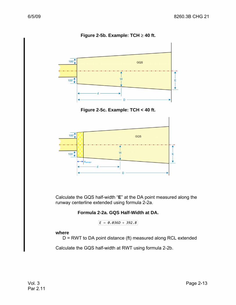
2.11.1 b. Width. The GQS lateral boundary is 100 ft from the runway edge at RWT. It expands uniformly to “E” feet (half-width) at DA (figures 2-5b and 2-5c).
6/5/09 8260.3B CHG 21
Vol. 3 Page 2-13 Par 2.11
Figure 2-5b. Example: TCH ≥ 40 ft.
Figure 2-5c. Example: TCH < 40 ft.
Calculate the GQS half-width “E” at the DA point measured along the runway centerline extended using formula 2-2a.
Formula 2-2a. GQS Half-Width at DA.
E 0.036D 392.8= +
where D = RWT to DA point distance (ft) measured along RCL extended
Calculate the GQS half-width at RWT using formula 2-2b.
XOFFSET

6/5/09 8260.3B CHG 21
Vol. 3 Page 2-14 Par 2.11
Formula 2-2b. GQS Half-Width at RWT.
widthRWYk 100
2= +
where RWYwidth = Runway width (ft)
Calculate the GQS half-width (w) at any distance “d” from RWT coordinates using formula 2-2c.
Formula 2-2c. GQS Half-Width, any distance (d).
E kw d k
D−⎛ ⎞= +⎜ ⎟
⎝ ⎠
where D = RWT coordinates to DA point dist. (ft) d = desired distance (ft) from RWT coordinates E = Formula 2-2a output k = Formula 2-2b output
2.11.1 c. If the course is offset from the runway centerline more than 3 degrees, expand the GQS area on the side of the offset as follows, referring to figures 2-5d and 2-5e:
STEP 1. Construct BC. Locate point "B" at the intersection of the runway centerline extended and a line perpendicular to the final approach course at the DA point. Calculate the half-width (E) of the GQS for the distance from point "B" to the RWT coordinates. Locate point "C" at distance "E" on a line perpendicular to the final approach course. Connect points "B" and "C."
STEP 2. Construct CD. Locate point "D" abeam the RWT coordinates on a line perpendicular to runway centerline at a point 100 ft from the runway edge. Connect points "C" and "D."
STEP 3. Construct DF. Locate point "F" abeam the RWT coordinates on a line perpendicular to runway centerline at a point 100 ft from the runway edge. (opposite point “D”). Connect points "D" and "F."
STEP 4. Construct AF. Locate point "A" on a line perpendicular to the runway centerline extended at distance "E" from point "B". Connect points "A" and "F."
STEP 5. Construct AB. Connect points "A" and "B."

6/5/09 8260.3B CHG 21
Vol. 3 Page 2-15 Par 2.11
Figure 2-5d. Example: TCH ≥ 40 ft.
D STEP 3LINE DF
STEP 2LINE CD
STEP 4LINE AF
STEP 1LINE BC
C
B
DA
A
GQS
FINAL APPROACHCOURSE
F
E
E
RWY
STEP 5LINE AB
Figure 2-5e. Example: TCH < 40 ft.
D STEP 3LINE DF
STEP 2LINE CD
STEP 4LINE AF
STEP 1LINE BC
C
B
DA
A
GQS
FINAL APPROACHCOURSE
F
E
E
D
F
XOFFSET
STEP 5LINE AB
Calculate the width of the offset side of the GQS trapezoid using formula 2-2d (see Vol. 3, chapter 2, figure 2-5f). Calculate the width of the non-offset side using formula 2-2a, except “D” = distance from RWT to Point B.
Formula 2-2d. GQS Offset Side Width, any distance (d).
( )
( )OFFSET
cos sin D i E k180 180
W d kD sin sin D i E
180 180
π πθ θ
π πθ θ
⎛ ⎞⎡ ⎤⎛ ⎞ ⎛ ⎞⋅ ⋅ − + −⎜ ⎟⎜ ⎟ ⎜ ⎟⎢ ⎥⎝ ⎠ ⎝ ⎠⎣ ⎦⎜ ⎟= +⎜ ⎟⎡ ⎤⎛ ⎞ ⎛ ⎞− ⋅ ⋅ − +⎜ ⎟⎜ ⎟ ⎜ ⎟⎢ ⎥⎝ ⎠ ⎝ ⎠⎣ ⎦⎝ ⎠
where d = desired distance (ft) from RWT coordinates cos = Cosine sin= Sine θ = FAC offset (degrees) D = RWT coordinates to Point “B” distance (ft)

6/5/09 8260.3B CHG 21
Vol. 3 Page 2-16 Par 2.11
i = RWT coordinates to FAC intersect. dist.(ft) E = Formula 2-2a output k = Formula 2-2b output
Figure 2-5f. Offset Calculation Example.
2.11.1 d. Clearance Surface. See Vol. 3, chapter 2, figure 2-5a. The GQS vertical characteristics reflect the glidepath characteristics of the procedure (e.g., the ILS/GLS/MLS/TLS/LPV based glidepath is a straight line in space and the Baro-VNAV vertical path (RNAV and RNP, LNAV/VNAV) is a curved line in space). Obstacles must not penetrate the GQS [see Vol. 3, chapter 2, paragraph 2.11.1d exceptions]. Calculate the height of the sloping GQS above THRe at any distance “d” (greater than XOFFSET) measured from runway threshold (RWT) coordinates along runway centerline (RCL) extended to a point abeam the obstacle using the appropriate formula:
Formula 2-3a. GQS Elevation
ILS/GLS/MLS/TLS or LPV.
( )OFFSET
ILSOFFSET
2r F V cos
3 180Z rd X 2
cosr 3 180
θ π
θ π
⎛ ⎞+ + ⋅⎜ ⎟⎝ ⎠= −
−⎛ ⎞+ ⋅⎜ ⎟⎝ ⎠
Where: r = mean earth radius (ft) F = THRe or LTP elevation VOFFSET = per paragraph 2.11.1a cos = cosine d = distance (ft) from RWT coordinates (greater than XOFFSET) XOFFSET = per paragraph 2.11.1a θ = GPA
4°
2570.0

6/5/09 8260.3B CHG 21
Vol. 3 Page 2-17 Par 2.11
Formula 2-3b. GQS Elevation
LNAV/VNAV or RNP.
( )( )
2d ‐ X tanOFFSET 3 180
rZ e r LTP V ‐ rBaro elev OFFSET
θ π⎛ ⎞⋅ ⋅⎜ ⎟⎝ ⎠
= ⋅ + +
where e = base of the natural logarithm (Napier’s constant) d = distance (ft) from RWT coordinates (greater than XOFFSET) XOFFSET = per paragraph 2.11.1a tan = tangent θ = GPA r = mean earth radius (ft) LTPelev = LTP elevation VOFFSET = per paragraph 2.11.1a
2.11.1 d. (1) For LPV (and ILS/GLS/MLS/TLS) procedures, the OCS is a flat plane (does not follow earth curvature); therefore, the height of the GQS at any point is equal to the height of surface on the runway centerline abeam it. Since the earth’s surface also curves away on the lateral as well as the longitudinal axis, the MSL elevation (OBSMSL) of an obstacle is reduced to account for earth curvature. This reduced value is termed the obstacle effective MSL elevation (OEE). Calculate OEE using formula 2-4 and compare to GQS height above THRe or LTP.
Formula 2-4. EC Adjusted Obstacle MSL Elevation.
( )EE MSLY
1O OBS r F 1
OBScos
r
⎛ ⎞⎜ ⎟⎜ ⎟= − + ⋅ −
⎛ ⎞⎜ ⎟⎜ ⎟⎜ ⎟⎝ ⎠⎝ ⎠
where OBSMSL = obstacle MSL elevation r = mean earth radius (ft) F = THRe or LTP elevation cos = cosine OBSY = perpendicular dist.(ft) from runway centerline to obstacle
2.11.1 d. (2) Obstacles permitted by AC 150/5300-13, Airport Design (or equivalent DoD airport design standard at military airfields) are excluded from GQS evaluation as follows.
2.11.1 d. (2) a. Obstacles with an effective height at or below an 80:1 surface (or DoD equivalent) originating at RWT coordinates (at THRe) and

6/5/09 8260.3B CHG 21
Vol. 3 Page 2-18 Par 2.11
extending a distance of 1,000 ft (figure 2-5g) are considered acceptable obstacles.
2.11.1 d. (2) b. Above-ground objects permitted by the airport design standard (e.g., AC 150/5300-13 paragraphs 305 and 308 or applicable DoD directive) are considered acceptable obstacles and are excluded from GQS evaluation.
Figure 2-5g. Allowable GQS Penetrations.
2. 12 ILS ANTENNA MAST HEIGHT LIMITATIONS FOR OBSTACLE CLEARANCE. The standard for locating the ILS antenna mast or monitor is a MINIMUM distance of 400 ft from the runway measured perpendicular to RCL. The antenna mast should not exceed 55 ft in height above the elevation of the runway centerline nearest it (see figure 2-6). At locations where it is not feasible for technical or economic reasons to meet this standard, the height and location of the antenna is restricted according to the following formula:

6/5/09 8260.3B CHG 21
Vol. 3 Page 2-19 Par 2.12
Figure 2-6. ILS Antenna Mast Height Limitations.
25'
5:1'
( )ant
ant
dh 255
d 5 h 25
= −
= +55'
400'250'
RCL
RWY
Where: hant = maximum height of mast above RCL abeam mast d = perpendicular distance from RCL (250' MINIMUM)


![Teori m[PleaseinsertPrerenderUnicode{ø}intopreamble]ter ... · Kasus og verbkongruens i LFG daupja pred daupjan ‘d˝pe 〈subj, obj〉’ subj pers 1 subj num sg ik pred ‘pro’](https://img.dokumen.tips/doc/110x75/5e63e9df4bc3df17253e95e0/teori-mpleaseinsertprerenderunicodefintopreambleter-kasus-og-verbkongruens.jpg)