Embed Size (px)
Citation preview

S CHAIN CONVEYOR
INS
TA
LL
AT
ION
MA
NU
AL
P/N
47
380
1
Trusted. Tested. True.

Chief Industries, Inc. 800-359-7600 P/N – 473801 Page 2
Chief Industries, Inc. – Agri/Industrial Division
Table of Contents
Manual Revisions ................................................................................................................. 3
STANDARD LIMITED WARRANTY ..................................................................................... 3
Before You Begin ............................................................................................................... 10
General Design Information ................................................................................................ 12
Accessory Equipment ......................................................................................................... 12
General Contractor Responsibilities ................................................................................... 12
Field Modifications and Installation Defects ....................................................................................... 12
Checking Shipment ............................................................................................................................. 13
Suggested Equipment ........................................................................................................................ 14
Hardware Torque ................................................................................................................................ 14
Chain conveyor Safety ....................................................................................................... 15
Pre-Installation Planning Information .................................................................................. 16
Component Identification .................................................................................................... 20
Component Installation ....................................................................................................... 23
Horizontal Body Assembly .................................................................................................................. 23
Chain Installation ................................................................................................................................ 27
Chain Tension ..................................................................................................................................... 29
Drive Installation ................................................................................................................................. 31
Intermediate Gate Installation ............................................................................................................. 36
Wiper Installation ................................................................................................................................ 38
Start up and Operation ....................................................................................................... 39
Periodic Maintenance ......................................................................................................................... 41
Troubleshooting .................................................................................................................. 42
Manufacturer Data / Recommendations ............................................................................. 44

C H A I N C O N V E Y O R
Chief Industries, Inc. 800-359-7600 OPERATION -473801 Page 3
Manual Revisions 5-28-2014
o Slack Chain
8-20-2014
o Updated warranty information
1-1-2016
o General formatting update
Chief Industries, Inc.
4400 East 39th Street • PO Box 848
Kearney, NE 68847
Phone 800.359.7600
For more information about Chief Industries, Inc. and additional products or services please visit our website
www.agri.Chiefind.com
STANDARD LIMITED WARRANTY Material Handling Products
C H A I N C O N V E Y O R
Chief Industries, Inc. 800-359-7600 OPERATION -473801 Page 4
1. Definitions. The following terms, when they appear in the body of this Standard Limited Warranty for Material Handling Products in initial capital letters shall have the meaning set forth below: A. Accepted Purchase Order shall mean the Purchase Order identified below. B. Chief shall mean Chief Agri/Industrial, a division of Chief Industries, Inc. C. Original Owner shall mean the original owner identified below. D. Product shall mean the Agri/Industrial Equipment as described in the Accepted Purchase Order. E. Reseller shall mean the authorized Chief Agri/Industrial Equipment dealer identified below.
2. Limited Product Warranty. Upon and subject to the terms and conditions set forth below,
Chief hereby warrants to the Reseller, and, if different, the Original Owner as follows: A. All new Products delivered to the Reseller or the Original Owner by Chief pursuant to the
Accepted Purchase Order will, when delivered, conform to the specifications set forth in the Accepted Purchase Order;
B. All new Products delivered pursuant to the Accepted Purchase Order will, in normal use and service, be free from defects in materials or workmanship; and
C. Upon delivery, Chief will convey good and marketable title to the Products, free and clear of any liens or encumbrances except for, where applicable, a purchase money security interest in favor of Chief.
3. Duration of Warranty and Notice Requirements. Subject to the Exceptions, Exclusions
and Limitations set forth below, the warranties set forth in Section 2 above shall apply to all covered non-conforming conditions that are discovered within the first twenty-four (24) months following delivery of the Product to the carrier designated by the Reseller and/or the Original Owner at Chief’s manufacturing facility in Kearney, Nebraska (the “Warranty Period”) and are reported to the Chief as provided in Section 4 below within thirty (30) days following discovery (a “Notice Period”).
4. Notice Procedure. In order to make a valid warranty claim, the Reseller and/or the Original
Owner must provide Chief with a written notice of any nonconforming condition discovered during the Warranty Period within the applicable Notice Period specified in Section 3 above. Said notice must be in writing; be addressed to Chief Industries, Inc., Agri/Industrial Division, Customer Service Department, P.O. Box 848, Kearney, NE 68848; and contain the following information: (a) the Customer’s name and address; (b) the Reseller’s name and address; (c) the make and model of the Product in question; (d) the current location of the Product; (e) a brief description of the problem with respect to which warranty coverage is claimed; and (f) the date on which the Product was purchased.
5. Exceptions and Exclusions. Anything herein to the contrary notwithstanding, the warranties
set forth in Section 2 above do not cover any of the following, each of which are hereby expressly excluded: A. Defects that are not discovered during the applicable Warranty Period; B. Defects that are not reported to the Chief Agri/Industrial Division Customer Service
Department in conformity with the notice procedure set forth in Section 4 above within the applicable Notice Period specified in Section 3;
C. Any used or pre-owned Products; D. Any Chief manufactured parts that are not furnished as a part of the Accepted Purchase Order; E. Any fixtures, equipment, materials, supplies, accessories, parts or components that have
been furnished by Chief but are manufactured by a third party;

C H A I N C O N V E Y O R
Chief Industries, Inc. 800-359-7600 OPERATION -473801 Page 5
F. Any Products which have been removed from the location at which they were originally installed; G. Any defect, loss, damage, cost or expense incurred by the Reseller or the Original Owner
to the extent the same arise out of, relate to or result, in whole or in part, from any one or more of the following: (i) Usual and customary deterioration, wear or tear resulting from normal use, service
and exposure; (ii) Theft, vandalism, accident, war, insurrection, fire or other casualty; (iii) Any damage, shortages or missing parts which result during shipping or are
otherwise caused by the Reseller, the Original Owner and/or any third party; (iv) Exposure to marine environments, including frequent or sustained salt or fresh
water spray; (v) Exposure to corrosive, chemical, ash, smoke, fumes, or the like generated or
released either within or outside of the structure on which the Product is installed, regardless of whether or not such facilities are owned or operated by the Reseller, the Original Owner or an unrelated third party;
(vi) Exposure to or contact with animals, animal waste and/or decomposition; (vii) The effect or influence the Product may have on surrounding structures, including,
without limitation, any loss, damage or expense caused by drifting snow; (viii) Any Product or portion thereof that has been altered, modified or repaired by the
Reseller, the Original Owner or any third party without Chief’s prior written consent;
(ix) Any Product or portion thereof that has been attached to any adjacent structure without Chief’s prior written approval;
(x) Any Product to which any fixtures, equipment, accessories, materials, parts or components which were not provided as a part of the original Accepted Purchase Order have been attached without Chief’s prior written approval;
(xi) The failure on the part of the Reseller, the Original Owner or its or their third party contractors to satisfy the requirements of all applicable statutes, laws, ordinances rules, regulations and codes, (including zoning laws and/or building codes);
(xii) The use of the Product for any purpose other than the purpose for which it was designed; and/or
(xiii) The failure of the Reseller, the Original Owner and/or any third party to: (a) properly handle, transport and/or store the Product or any component part
thereof; (b) properly select and prepare a site that is adequate for the installation and/or
operation of the Product or any component part thereof; (c) properly design and construct a foundation that is adequate for the
installation and/or operation of the Product or any component part thereof; (d) properly set up, erect, construct or install the Product and/or any
component part thereof; and/or (e) properly operate, use, service and/or maintain the Product and each
component part thereof. 6. Resolution of Warranty Claims. In the event any nonconforming condition is discovered
within the Warranty Period and Chief is notified of a warranty claim as required by Section 4 prior to the end of the applicable Notice Period set forth in Section 3 above, Chief shall, with the full cooperation of the Reseller and the Original Owner, immediately undertake an investigation of such claim. To the extent Chief shall determine, in its reasonable discretion, that the warranty claim is covered by the foregoing Limited Product Warranty, the following shall apply:

C H A I N C O N V E Y O R
Chief Industries, Inc. 800-359-7600 OPERATION -473801 Page 6
A. Warranty Claims With Respect to Covered Non-Conforming Conditions Discovered Within the First Three Hundred Sixty Five (365) Days and Reported to Chief Within Thirty (30) Days of Discovery. In the case of a warranty claim which relates to a covered non-conforming condition that is discovered during the first three hundred sixty five (365) days of the Warranty Period and is reported to Chief as required by Section 4 within thirty (30) days of discovery as required by Section 3, Chief will, as Chief’s sole and exclusive obligation to the Reseller and the Original Owner, and as their sole and exclusive remedy, work in cooperation with the Reseller and the Original Owner to correct such non-conforming condition, and in connection therewith, Chief will ship any required replacement parts to the “ship to address” set forth in the Accepted Purchase Order FOB Chief’s facilities in Kearney, Nebraska, and will either provide the labor or reimburse the Reseller or the Original Owner, as may be appropriate in the circumstances, for any out of pocket expense the Original Owner may reasonably and necessarily incur for the labor that is required to correct such non-conforming condition, provided that if work is to be performed by the Reseller or a third party contractor, Chief may require at least two competitive bids to perform the labor required to repair or correct the defect and reserves the right to reject all bids and obtain additional bids. Upon acceptance of a bid by Chief, Chief will authorize the necessary repairs.
B. All Other Warranty Claims. Except as is otherwise provided in subsection 6A above, in the case of all other warranty claims which relate to covered non-conforming conditions that are discovered during the Warranty Period and are reported to Chief as required by Section 4 within thirty (30) days following discovery, Chief will, as Chief’s sole and exclusive obligation to the Reseller and the Original Owner, and as the Reseller’s and the Original Owner’s sole and exclusive remedy, ship any required replacement parts to the Original Owner at the “ship to address” specified in the Accepted Purchase Order FOB Chief’s facilities in Kearney, Nebraska; and in such event, Chief shall have no responsibility or liability to either the Reseller or the Original Owner for the cost of any labor required to repair or correct the defect.
7. Warranty Not Transferable. This Warranty applies only to the Reseller and the Original
Owner and is not transferable. As such, this Warranty does not cover any Product that is sold or otherwise transferred to any third party following its delivery to the Original Owner.
8. Limitation on Warranties, Liabilities and Damages. The Reseller and the Original Owner
expressly agree that the allocation of the risk, liability, loss, damage, cost and expense arising from any Product that does not conform to the limited warranty given in Section 2 above are fair and reasonable and acknowledge that such allocation was expressly negotiated by the parties and was reflected in the Purchase Price of the Product. Accordingly the Reseller and the Original Owner expressly agree as follows: A. Disclaimer of Implied Warranties. EXCEPT AS IS OTHERWISE EXPRESSLY SET
FORTH HEREIN, CHIEF MAKES NO OTHER REPRESENTATIONS OR WARRANTIES OF ANY KIND WHATSOEVER, WHETHER EXPRESS OR IMPLIED, BY OPERATION OF LAW, COURSE OF DEALING OR OTHERWISE WITH RESPECT TO THE PRODUCT, ANY COMPONENT PART THEREOF OR ANY OTHER GOODS OR SERVICES THAT CHIEF MANUFACTURES, FABRICATES, PRODUCES, SELLS OR PROVIDES TO THE DEALER OR THE ORIGINAL OWNER PURSUANT TO THE TERMS OF ANY ACCEPTED PURCHASE ORDER, INCLUDING WITHOUT LIMITATION ANY REPRESENTATION OR WARRANTY WITH RESPECT TO DESIGN, CONDITION, MERCHANTABILITY OR FITNESS OF THE PRODUCT OR ANY OTHER GOODS OR SERVICES FOR ANY PARTICULAR PURPOSE OR USE.
B. Limitation on Liability. EXCEPT AS IS OTHERWISE EXPRESSLY SET FORTH IN SECTION 6 ABOVE, CHIEF'S LIABILITY TO THE DEALER AND/OR THE ORIGINAL

C H A I N C O N V E Y O R
Chief Industries, Inc. 800-359-7600 OPERATION -473801 Page 7
OWNER WITH RESPECT TO ANY DEFECTS IN ANY PRODUCTS OR FOR ANY OTHER GOODS OR SERVICES WHICH DO NOT CONFORM TO THE WARRANTIES SET FORTH ABOVE SHALL NOT, IN ANY EVENT, EXCEED THE ACTUAL COST OF SUCH NON-CONFORMING PRODUCT, GOODS OR SERVICES AS DETERMINED PURSUANT TO THE ACCEPTED PURCHASE ORDER; AND
C. Limitation on the Nature of Damages. EXCEPT AS EXPRESSLY PROVIDED IN SECTION 6 ABOVE, CHIEF SHALL NOT, UNDER ANY CIRCUMSTANCES, BE LIABLE TO THE DEALER, THE ORIGINAL OWNER OR ANY THIRD PARTY FOR ATTORNEY FEES COURT COSTS OR ANY OTHER SPECIAL, INDIRECT, INCIDENTAL, CONSEQUENTIAL, LIQUIDATED OR PUNITIVE DAMAGES OF ANY NAME, NATURE OR DESCRIPTION AS A RESULT OF THE FAILURE OF ANY PRODUCT OR ANY OTHER GOODS OR SERVICES PURCHASED BY THE DEALER OR THE ORIGINAL OWNER FROM CHIEF PURSUANT TO THE ACCEPTED PURCHASE ORDER TO CONFORM TO THE LIMITED WARRANTIES SET FORTH IN SECTION 2 ABOVE.
8. Applicable Law. This Limited Product Warranty has been issued, accepted and entered into
by the Reseller, the Original Owner and Chief in the State of Nebraska and shall be governed by, and construed in accordance with, the internal laws of the State of Nebraska. Any legal action or proceeding with respect to any goods or services furnished to the Original Owner by Chief in connection herewith, or any document related hereto shall be brought only in the district courts of Nebraska, or the United States District Court for the District of Nebraska, and, by execution and delivery of this Limited Product Warranty, the undersigned Original Owner hereby accept for themselves and with respect to their property, generally and unconditionally, the jurisdiction of the aforesaid courts. Further, the undersigned Original Owner hereby irrevocably waives any objection, including, without limitation, any forum non conveniens, which it may now or hereafter have to the bringing of such action or proceeding in such respective jurisdictions.
ACKNOWLEDGMENT OF RECEIPT
By its signature hereto, the undersigned Reseller represents and warrants to Chief that the Reseller has provided a true, correct and complete copy of this Standard Limited Warranty to the Original Owner at the time the product was purchased. Reseller Name and Address: _______________________________ _______________________________ _______________________________ Original Owner Name and Address: _______________________________ _______________________________ _______________________________ Accepted Purchase Order No. _________________________ Original Jobsite Address: _____________________________________ _____________________________________ _____________________________________

C H A I N C O N V E Y O R
Chief Industries, Inc. 800-359-7600 OPERATION -473801 Page 8
RESELLER: By: _________________________________ Date ____________________________________ Print name and title 4831-5139-8433, v. 1

C H A I N C O N V E Y O R
Chief Industries, Inc. 800-359-7600 OPERATION -473801 Page 9
Warning
Water Sensitive Materials - Read this notice carefully
Items must be inspected and carrier advised immediately if damage is noted. White rust is a corrosion attack of the zinc coating resulting from the presence of water. Anywhere rust is found will result in a reduction of the life of the galvanized steel.
If water has entered a bundle or if condensation has formed between items, the bundle must be opened, the items separated and all surfaces dried.
If items are to be installed within 10 days:
Store bundled items off the ground high enough to allow air circulation beneath bundle and to prevent water from entering. Store 1 end at least 8” (20.32cm) higher than the opposite end. Support long bundles in the center. Prevent rain from entering the bundle by covering with a tarpaulin, making provision for air circulation between the draped edges and the ground.
Do not wrap in plastic.
If items are not to be installed within 10 days:
Provide inside dry storage. Storage beyond 6 months is not recommended. If white rust is apparent upon receipt of shipment, notify Chief immediately. Damage to items, resulting from improper storage, is the responsibility of the receiver.

C H A I N C O N V E Y O R
Chief Industries, Inc. 800-359-7600 OPERATION -473801 Page 10
Before You Begin
Before starting the installation of the chain conveyor, take time to thoroughly study the construction methods in this manual, this will save you time and money.
Chief makes no warranty concerning components, accessories or equipment not manufactured by Chief.
When using a cutting torch or welding galvanized material, the possibility of developing toxic fumes will exist. Provide adequate ventilation and respiratory protection when using this type of equipment during installation.
Introduction
Thank you for purchasing a Chief chain conveyor. Proper installation and operation will ensure you the best overall experience with your equipment and guarantee smooth operation.
This proprietary information is loaned with the expressed agreement that the drawings and information therein contained are the property of Chief Industries, Inc. and will not be reproduced, copied, or otherwise disposed of, directly or indirectly, and will not be used in whole or in part to assist in making or to furnish any information for the making of drawings, prints or other reproduction hereof, or for the making of additional products or equipment except upon written permission of Chief Industries, Inc. first obtained and specific as to each case. The acceptance of this material will be construed as an acceptance of the foregoing agreement.
The technical data contained herein is the most recent available at the time of publication and is subject to modification without notice. Chief Industries, Inc. reserves the right to modify the construction and method of operation of their products at any time without any obligation on their part to modify any equipment previously sold and delivered.
Important Note: If you are unable to remedy any service problem after thoroughly studying this manual, contact the dealer from whom you purchased the unit. Your dealer is your first line of service. The following information is required for service:
1. Chain conveyor model and serial number: ___________________________
2. Sprocket size and number of teeth: __________________________________
3. Overall length: ______________________________
4. Motor RPM and HP: _____________________________________
5. Type of grain and capacity: ___________________________________
6. Dealer purchased from: _________________________________
7. Dealer address and phone number: ________________________
8. Date purchased: _______________________________________
9. Service contractor:
a. Name: _____________________________________________
b. Address: ____________________________________________
c. Phone: _____________________________________________
C H A I N C O N V E Y O R
Chief Industries, Inc. 800-359-7600 OPERATION -473801 Page 11
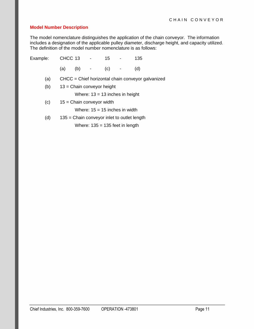
Model Number Description
The model nomenclature distinguishes the application of the chain conveyor. The information includes a designation of the applicable pulley diameter, discharge height, and capacity utilized. The definition of the model number nomenclature is as follows:
Example: CHCC 13 - 15 - 135
(a) (b) - (c) - (d)
(a) CHCC = Chief horizontal chain conveyor galvanized
(b) 13 = Chain conveyor height
Where: 13 = 13 inches in height
(c) 15 = Chain conveyor width
Where: 15 = 15 inches in width
(d) 135 = Chain conveyor inlet to outlet length
Where: 135 = 135 feet in length

C H A I N C O N V E Y O R
Chief Industries, Inc. 800-359-7600 OPERATION -473801 Page 12
General Design Information
All steel materials are purchased in accordance with the applicable ASTM Standard.
All bolted connections are designed using high strength bolts which meet the specifications of the applicable ASTM or SAE standard.
All galvanized steel conform to ASTM specification A653 with the galvanized coating to ASTM specification A924.
Galvanized coating type G-115 specifies galvanization of 1.15 oz/ft2 (Z350; 350 gm/m2) total for both sides in the following materials:
22 Gauge thickness & lighter = Commercial Steel Type A, 33ksi min yield (grade 230)
18 & 20 Gauge thickness = Structural Steel Grade 40, Class I; 40ksi min yield (grade
275)
17 Gauge thickness & heavier = Structural Steel Grade 55, Class I; 55ksi min yield
(grade 340)
Accessory Equipment
All accessory equipment should be installed and maintained in accordance with each individual supplier’s installation and operation instructions. However, if any modifications to the Chief standard design are required, contact Chief for special recommendations.
Important Note: Do not modify the chain conveyor design without Chief approval. It is the responsibility of the general contractor to verify that all equipment is properly installed and that the equipment is compatible with the intended use. A qualified electrician should be contracted to complete all electrical wiring and servicing.
General Contractor Responsibilities
It is the responsibility of the general contractor to verify that the complete system (chain conveyor, and other accessory equipment) is constructed with quality workmanship and that all equipment is installed per the respective manufacturer's instructions.
In addition, the general contractor is responsible for the fitness of use of any system which he constructs. All accessory equipment incorporated into the system should be approved for the intended use by each respective equipment manufacturer.
Field Modifications and Installation Defects
Chief assumes no responsibility for field modifications or installation defects which result in structural damage or storage quality problems. If any field modifications are necessary which are not specifically covered by the contents of the installation manual, contact Chief for approval. Any unauthorized modification or installation defect which affects the structural integrity of the chain conveyor will void the warranty.

C H A I N C O N V E Y O R
Chief Industries, Inc. 800-359-7600 OPERATION -473801 Page 13
Checking Shipment
For your convenience individual items will be labeled with an appropriate part number and packages labeled. Hardware, including bolts, nuts, screws and other small clips or brackets may be divided into smaller packages for ease of use and identification.
Check your shipment at the time of delivery against the packing list provided with the shipment. If any items are missing or any damaged material is evident, note such shortage or damage on the freight bill before you sign the shipment paperwork.
Claims of shortages will not be honored after 30 days from receipt of shipment. Parts that are missing or damaged are the responsibility of the delivering carrier, not the manufacturer or dealer.
It is advisable to reorder damaged or missing parts immediately so that there will be no delay in the installation. After receiving the invoice for the reordered material, file a claim with the delivering carrier immediately.

C H A I N C O N V E Y O R
Chief Industries, Inc. 800-359-7600 OPERATION -473801 Page 14
Suggested Equipment
Chief recommends the following equipment and tools needed for installation. Individual installations may vary.
Impact wrenches and sockets
End wrenches
Crescent wrenches
Vise grip pliers
Alignment punches
Rubber mallets
Level
Drill and drill bits
Screw Guns
Metal Saw
Extension cords
Hardware Torque
The following table contains recommended minimum and maximum torque values for installation.
When installing hardware the minimum and maximum torque values shown below must be followed. All hardware must seat tight against the corresponding bin component.
Bolt Diameter Minimum Torque Maximum Torque
5/16” (.79cm) 22 ft.-lbs. 28 ft.-lbs.
3/8” (.95cm) 25 ft.-lbs. 44 ft.-lbs.
7/16” (1.11cm) 60 ft.-lbs. 75 ft.-lbs.
1/2" (1.27cm) 50 ft.-lbs. 58 ft.-lbs.
Please note the following wrench / socket size to be used on the corresponding hardware:
Bolt Size Head Size Nut Size
5/16” 1/2” wrench 1/2" wrench
3/8” 9/16” wrench 9/16” wrench
7/16” 5/8” wrench 11/16” wrench
1/2” 3/4” wrench 3/4" wrench
C H A I N C O N V E Y O R
Chief Industries, Inc. 800-359-7600 OPERATION -473801 Page 15
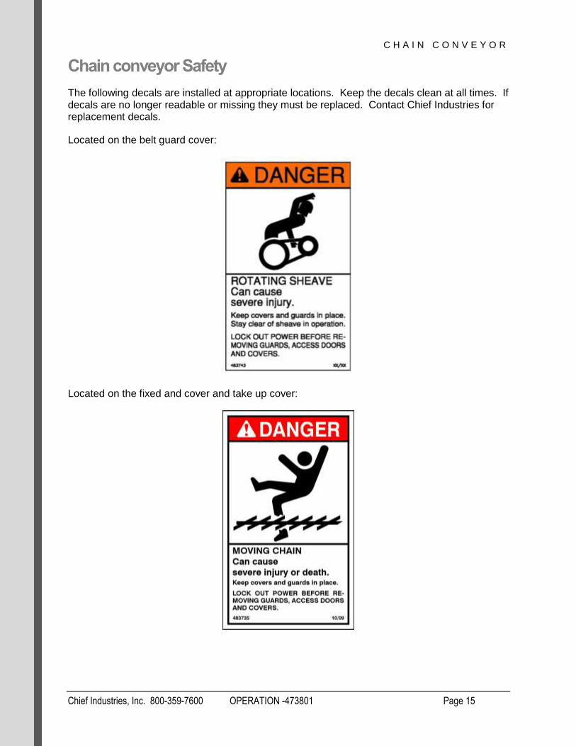
Chain conveyor Safety
The following decals are installed at appropriate locations. Keep the decals clean at all times. If decals are no longer readable or missing they must be replaced. Contact Chief Industries for replacement decals.
Located on the belt guard cover:
Located on the fixed and cover and take up cover:

C H A I N C O N V E Y O R
Chief Industries, Inc. 800-359-7600 OPERATION -473801 Page 16
Pre-Installation Planning Information
Chain conveyors should be preplanned to meet the project requirements. Engineering drawings will simplify the installation and should include the following:
Site layout
Capacities
Location and orientation of chain conveyor
Location of accessories
The general installation of the chain conveyor components will be in the following order.
1. Install head section
2. Install intermediate sections
3. Install tail section
Important Note: Never weld the conveyor to the support structures. Bolting allows for realignment of sections and replacement if necessary.
C H A I N C O N V E Y O R
Chief Industries, Inc. 800-359-7600 OPERATION -473801 Page 17
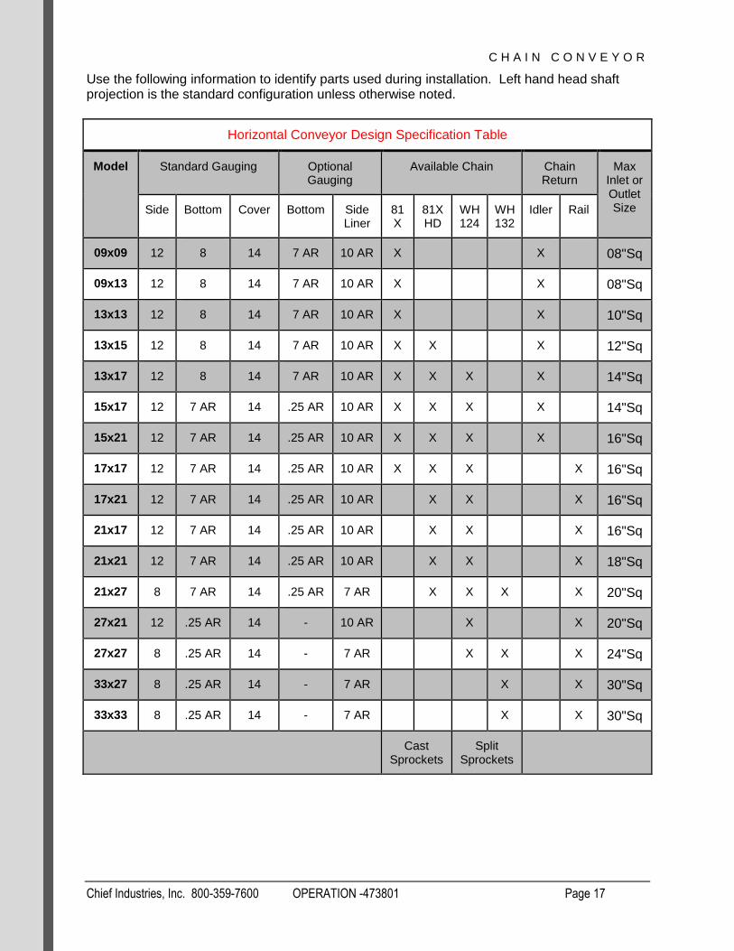
Use the following information to identify parts used during installation. Left hand head shaft projection is the standard configuration unless otherwise noted.
Horizontal Conveyor Design Specification Table
Model Standard Gauging Optional Gauging
Available Chain Chain Return
Max Inlet or Outlet Size Side Bottom Cover Bottom Side
Liner 81X
81XHD
WH124
WH132
Idler Rail
09x09 12 8 14 7 AR 10 AR X
X
08"Sq
09x13 12 8 14 7 AR 10 AR X
X
08"Sq
13x13 12 8 14 7 AR 10 AR X
X
10"Sq
13x15 12 8 14 7 AR 10 AR X X
X
12"Sq
13x17 12 8 14 7 AR 10 AR X X X
X
14"Sq
15x17 12 7 AR 14 .25 AR 10 AR X X X
X
14"Sq
15x21 12 7 AR 14 .25 AR 10 AR X X X
X
16"Sq
17x17 12 7 AR 14 .25 AR 10 AR X X X
X 16"Sq
17x21 12 7 AR 14 .25 AR 10 AR
X X
X 16"Sq
21x17 12 7 AR 14 .25 AR 10 AR
X X
X 16"Sq
21x21 12 7 AR 14 .25 AR 10 AR
X X
X 18"Sq
21x27 8 7 AR 14 .25 AR 7 AR
X X X
X 20"Sq
27x21 12 .25 AR 14 - 10 AR
X
X 20"Sq
27x27 8 .25 AR 14 - 7 AR
X X
X 24"Sq
33x27 8 .25 AR 14 - 7 AR
X
X 30"Sq
33x33 8 .25 AR 14 - 7 AR
X
X 30"Sq
Cast Sprockets
Split Sprockets

C H A I N C O N V E Y O R
Chief Industries, Inc. 800-359-7600 OPERATION -473801 Page 18
Horizontal Conveyor Chain and Paddle Specifications
Model
81X (Paddles 10.4” O.C. 81X (Paddles 10.4” O.C.
10’ Roll requires 12 Paddles 10’ Roll requires 12 Paddles
Model Chain Paddle Model Chain Paddle
09x09 X 9107594 9162181
09x13 X 9107594 9162181
13x13 X 9107599 9188576
13x15 X 9107599 9188576 X 9112914 9188576
13x17 X 9107599 9188576 X 9112914 9188576
15x17 X 9107602 9187354 X 9112914 9187354
15x21 X 9107602 9187354 X 9112914 9187354
17x17 X 9107595 9218586 X 9115064 9218586
17x21 X 9115064 9218586
21x17 X Consult Chief
Consult Chief
21x21 X Consult Chief
Consult Chief
21x27 X Consult Chief
Consult Chief
27x21
27x27
33x27
33x33
Cast Sprockets

C H A I N C O N V E Y O R
Chief Industries, Inc. 800-359-7600 OPERATION -473801 Page 19
Horizontal Conveyor Chain and Paddle Specifications
Model
WH124 (Paddles 12” O.C. WH132 (Paddles 12” O.C.
10’ Roll requires 10 Paddles 5’ Roll requires 5 Paddles
Model Chain Paddle Model Chain Paddle
09x09
09x13
13x13
13x15
13x17 X Consult Chief
Consult Chief
15x17 X Consult Chief
Consult Chief
15x21 X Consult Chief
Consult Chief
17x17 X 9119824 9119825
17x21 X 9119824 9119825
21x17 X 9120991 9120992
21x21 X 9120991 9120992
21x27 X 9120991 9120992 X Consult Chief
Consult Chief
27x21 X 9120915 9121790
27x27 X 9120915 9121790 X 9115171 9115172
33x27 X 9122295 9113807
33x33 X 9122295 9113807
Split Sprockets

C H A I N C O N V E Y O R
Chief Industries, Inc. 800-359-7600 OPERATION -473801 Page 20
Component Identification Chief does not assume any responsibility from parts damaged due to faulty or improper installation procedures.
Horizontal Chain Conveyor
C H A I N C O N V E Y O R
Chief Industries, Inc. 800-359-7600 OPERATION -473801 Page 21
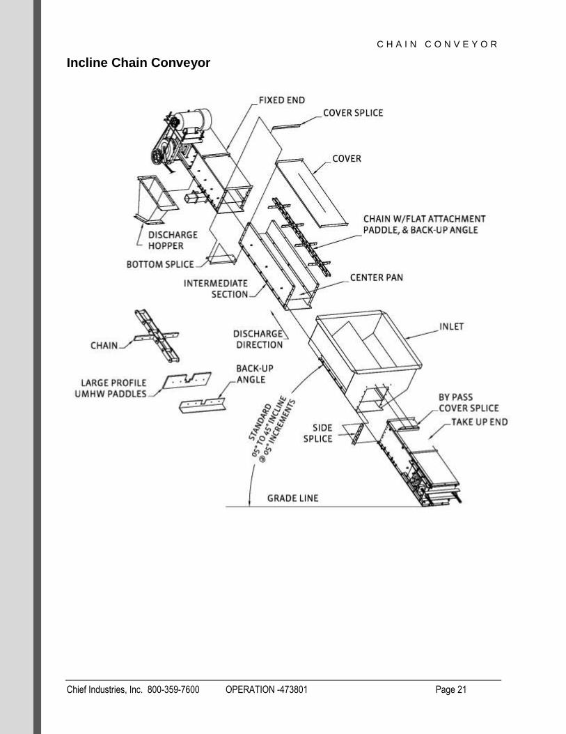
Incline Chain Conveyor

C H A I N C O N V E Y O R
Chief Industries, Inc. 800-359-7600 OPERATION -473801 Page 22
Horizontal Incline Chain Conveyor
C H A I N C O N V E Y O R
Chief Industries, Inc. 800-359-7600 OPERATION -473801 Page 23
Component Installation
Horizontal Body Assembly
Important Note: Chain conveyor body assemblies may be shipped assembled or as separate components.
To assemble conveyor body sections, please take note of the following steps and corresponding illustrations.
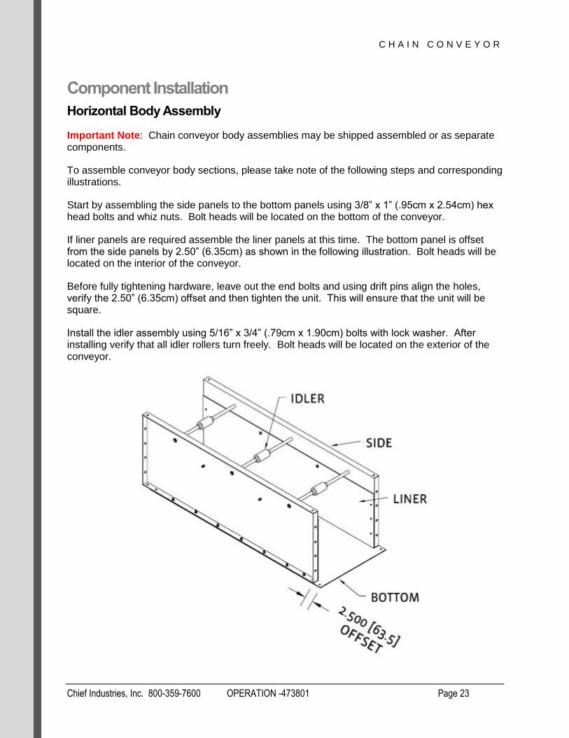
Start by assembling the side panels to the bottom panels using 3/8” x 1” (.95cm x 2.54cm) hex head bolts and whiz nuts. Bolt heads will be located on the bottom of the conveyor.
If liner panels are required assemble the liner panels at this time. The bottom panel is offset from the side panels by 2.50” (6.35cm) as shown in the following illustration. Bolt heads will be located on the interior of the conveyor.
Before fully tightening hardware, leave out the end bolts and using drift pins align the holes, verify the 2.50” (6.35cm) offset and then tighten the unit. This will ensure that the unit will be square.
Install the idler assembly using 5/16” x 3/4” (.79cm x 1.90cm) bolts with lock washer. After installing verify that all idler rollers turn freely. Bolt heads will be located on the exterior of the conveyor.
C H A I N C O N V E Y O R
Chief Industries, Inc. 800-359-7600 OPERATION -473801 Page 24
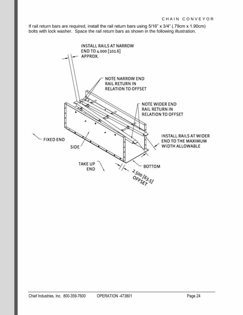
If rail return bars are required, install the rail return bars using 5/16” x 3/4” (.79cm x 1.90cm) bolts with lock washer. Space the rail return bars as shown in the following illustration.
C H A I N C O N V E Y O R
Chief Industries, Inc. 800-359-7600 OPERATION -473801 Page 25
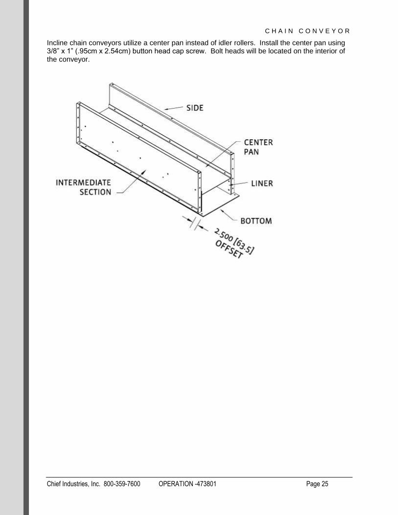
Incline chain conveyors utilize a center pan instead of idler rollers. Install the center pan using 3/8” x 1” (.95cm x 2.54cm) button head cap screw. Bolt heads will be located on the interior of the conveyor.

C H A I N C O N V E Y O R
Chief Industries, Inc. 800-359-7600 OPERATION -473801 Page 26
Start at the head section and connect the sections together at the bolted flanges using 3/8” x 1” (.95cm x 2.54cm) hex head bolts and whiz nuts. Complete the conveyor assembly leaving covers off for chain installation.
Attach all bottom splices and only hand tighten at this time. Verify that all surfaces at the joint locations are flush, including center pan alignment if used in your application.
Connect the bottom splice using 3/8” x 1-1/4” (.95cm x 3.17cm) hex head bolts and whiz nuts. Bolt heads are to be located on the bottom of the conveyor.

C H A I N C O N V E Y O R
Chief Industries, Inc. 800-359-7600 OPERATION -473801 Page 27
Chain Installation
Important Note: The chain may be installed at any time during the assembly process. The paddles are attached prior to the chain installation, with paddles bolted to every attachment.
Prior to the chain installation, install the paddles to each chain attachment using 5/16” x 1.25” (.79cm x 3.17cm) bolts and nylock nuts.
When using 1/2" (1.27cm) thick paddles, recycle cups or backup angles, 5/16” x 1.50” (.79cm x 3.81cm) bolts are required.

C H A I N C O N V E Y O R
Chief Industries, Inc. 800-359-7600 OPERATION -473801 Page 28
Important Note: When recycle cups are used, install 2 recycle cups per paddle on every third paddle.
Important Note: When installing WH124 and WH132 roller chain verify that the relationship between sprocket revolution, discharge direction, and chain orientation (chain narrow end - chain wide end) is correct.

C H A I N C O N V E Y O R
Chief Industries, Inc. 800-359-7600 OPERATION -473801 Page 29
Chain Tension
The amount of chain tension required will vary with each conveyor. Conveyor capacity, conveyor length, characteristics of the conveyed product, and chain speed will factor into the chain tension required for a conveyor.
The chain tension will need to be tight enough so it does not jump a sprocket tooth or accumulate enough slack on the return side at the driven sprocket to cause the chain to catch an additional tooth as the chain continues to wrap around the sprocket.
Correct tension will prevent either a loose condition or excessive tension resulting in premature failure of the chain and sprocket.
C H A I N C O N V E Y O R
Chief Industries, Inc. 800-359-7600 OPERATION -473801 Page 30
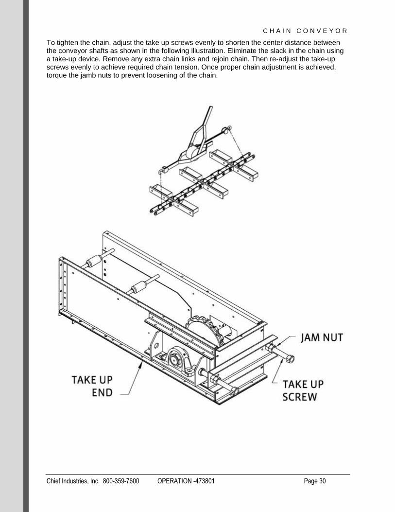
To tighten the chain, adjust the take up screws evenly to shorten the center distance between the conveyor shafts as shown in the following illustration. Eliminate the slack in the chain using a take-up device. Remove any extra chain links and rejoin chain. Then re-adjust the take-up screws evenly to achieve required chain tension. Once proper chain adjustment is achieved, torque the jamb nuts to prevent loosening of the chain.

C H A I N C O N V E Y O R
Chief Industries, Inc. 800-359-7600 OPERATION -473801 Page 31
Drive Installation
Refer to the following illustration for orientation of components. Shown is a left hand configuration.
1. Install reducer drive that is packaged separately, according to the manufacturer’s
complete instructions.
2. Mount electric motor onto motor mount base
3. Move motor mount to align front of motor with front of reducer.
4. Install torque arm
5. If required install optional fan kit according to manufacturer’s directions.
6. Install belt guard according to manufacturer’s directions.
7. Install sheaves leaving clearance between back of sheaves and front of motor and
reducer for belt guard installation.
8. Install v-belts and adjust motor mount base to tighten belts.
9. Install belt guard / reducer bracket.

C H A I N C O N V E Y O R
Chief Industries, Inc. 800-359-7600 OPERATION -473801 Page 32
Important Note: Reducer drives are shipped without lubricant. Do not operate the chain conveyor until the reducer drive has been filled with an approved lubricant as described in the manufacturer’s instructions.
Position the motor on the fixed end motor mount and attach with the bolt package provided. Adjustment to the motor mount may be required so that the end of the motor shaft is in line with the end of the reducer input shaft.
Install the drive belts and adjust belt tension. Using a belt tension checker adjust the belts so that a force in the middle of each belt will deflect the belt 1/64” for each inch of distance between the sheave centers.

C H A I N C O N V E Y O R
Chief Industries, Inc. 800-359-7600 OPERATION -473801 Page 33
Important Note: Compare the force you have applied with the values in the following chart. The force should be between the minimum and maximum shown. The maximum value shown is for a “New Belt”, and new belts should be tensioned at this value to allow for expected tension loss. Used belts should be maintained at the minimum value.
Cross Section
Smallest Sheave Diameter Range
(in)
RPM Range
Belt Deflction Force (lbs)
Super Gripbelt
Gripnotch Belt
Min Max Min Max
3V
2.2-2.4
1000-2500
- - 3.3 4.9
2501-4000
- - 2.9 4.3
2.65-3.65
1000-2500
3.6 5.1 4.2 6.2
2501-4000
3.0 4.4 3.8 5.6
4.12-6.90
1000-2500
4.9 7.3 5.3 7.9
2501-4000
4.4 6.6 4.9 7.3
5V
4.4-6.7
500-1749 - - 10.2 15.2
1750-3000
- - 8.8 13.2
3001-4000
- - 5.6 8.5
7.1-10.9
500-1740 12.7 18.9 14.8 22.1
1741-3000
11.2 16.7 13.7 20.1
11.8-16.0
500-1740 15.5 23.4 17.1 25.5
1741-3000
14.6 21.8 16.8 25.0
The ideal tension is the lowest tension at which the belt will not slip under peak load conditions (over tensioning shortens belt and bearing life). Check tension frequently during the first 24 hours to 48 hours of operation.

C H A I N C O N V E Y O R
Chief Industries, Inc. 800-359-7600 OPERATION -473801 Page 34
Important Note: All sheaves, sprockets, and drive components assembled at the manufacturer (including the chain conveyor pulley) should be checked for alignment, centered and tightened prior to operation and at regular operating intervals.

C H A I N C O N V E Y O R
Chief Industries, Inc. 800-359-7600 OPERATION -473801 Page 35
Install the belt guard and drive components. Since configurations and bracketing of belt guards differ per model and reducer drive, refer to the supplemental drawings shipped with the drive package for installation instructions on your specific model. Install the belt guard back panels and bracketing. Adjust the belt guard bracketing to allow for back panel clearance away from motor & reducer. Install sheaves and belts allowing for clearance away from back panels. Complete the installation by placing belt guard shell over the sheaves and belts and then attaching the shell to the back panels
Important Note: Do not operate the chain conveyor without a correctly installed belt guard assembly.
Important Note: Explosion proof electrical equipment must be used whenever a chain conveyor is located in an explosive environment. A safety switch should be installed on the fixed end section to prevent accidental motor operation when servicing any components.

C H A I N C O N V E Y O R
Chief Industries, Inc. 800-359-7600 OPERATION -473801 Page 36
Intermediate Gate Installation
Intermediate bottom and bottom cover (if applicable) must be trimmed to noted dimensions to allow for proper sealing between the intermediate section and the gate. Trim bottom and bottom cover (if applicable) and install gate shims and intermediate gate as shown in the following illustration.
First locate the bolts in the bottom of the conveyor closest to the center of the intermediate gate inlet. Verify that the existing intermediate bottom bolts align with the slots in the gate top flange.
Next mark the gate centerline on the intermediate bottom and bottom cover if applicable. Remove and cut the intermediate bottom and bottom cover if applicable according to the following dimensions.
Gate Length A B C
30” 17.125” (43.50cm) 34.25” (87.00cm) 71.50” (181.61cm)
40” 22.125” (56.20cm) 44.25” (112.40cm) 91.50” (232.41cm)
50” 27.125” (68.90cm) 54.25” (137.80cm) 111.5” (283.21cm)
Next reinstall the intermediate bottom and bottom cover if applicable downstream of the gate. Install the upstream bottom, bottom cover if applicable, and gate. Reuse all hardware from the intermediate bottom and bottom cover if applicable.

C H A I N C O N V E Y O R
Chief Industries, Inc. 800-359-7600 OPERATION -473801 Page 37
C H A I N C O N V E Y O R
Chief Industries, Inc. 800-359-7600 OPERATION -473801 Page 38
Wiper Installation
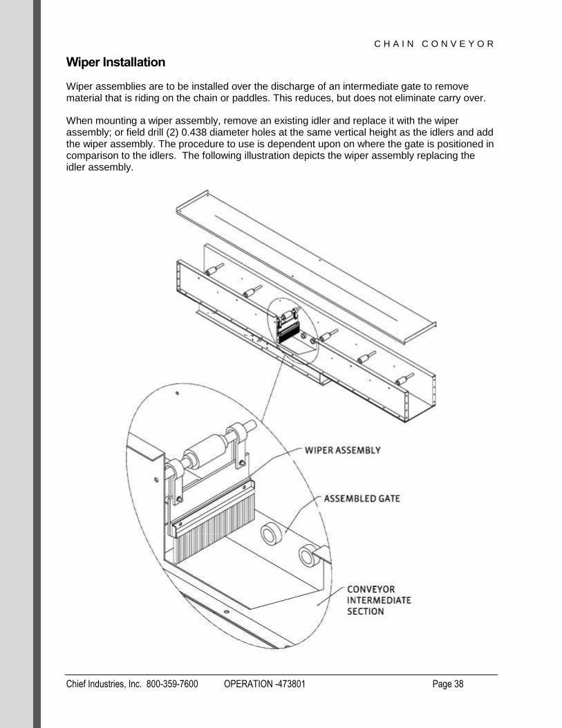
Wiper assemblies are to be installed over the discharge of an intermediate gate to remove material that is riding on the chain or paddles. This reduces, but does not eliminate carry over.
When mounting a wiper assembly, remove an existing idler and replace it with the wiper assembly; or field drill (2) 0.438 diameter holes at the same vertical height as the idlers and add the wiper assembly. The procedure to use is dependent upon on where the gate is positioned in comparison to the idlers. The following illustration depicts the wiper assembly replacing the idler assembly.

C H A I N C O N V E Y O R
Chief Industries, Inc. 800-359-7600 OPERATION -473801 Page 39
Start up and Operation
Prior to operating the conveyor, check all areas for safety issues and machine damage which could occur during operation. Follow all manufacturers’ pre-start up instructions for each individual component provided with your conveyor. In addition verify the following:
All debris is removed from the conveyor.
Conveyor sections are properly aligned and square
Return rails and idler rollers turn freely
Paddles do not interfere with sides of conveyor
All hardware is in place with correct torque
Dive and take up sprockets are centered across the width of the conveyor and square
with the conveyor housing
Secure set screws in bearings, drive sheaves, head and tail shafts, and gear reducers
and drive sprocket key is secured in place
Sheaves properly aligned and V-belts properly tensioned
Bushing bolts in sheaves and reducer are torqued to manufacturer specifications
Chain tension is correct
Drive guard and other safety devices installed
Inspection section panels in place and properly secured
Discharge area free of obstructions
Reducer installed to manufacturer specifications
Reducer has lubricant and is filled to proper level
Safety restrictions on electric controls
Electrical equipment is installed to meet national electric code and/ or local safety codes,
including explosion proof equipment where required
After an initial pre-start inspection, operate the chain conveyor empty under power for a period of time to verify the chain is tracking correctly on the sprockets and idlers. If there is excess slack in the chain, adjust the take up evenly. Monitor the belts and sheaves for correct belt tension and sheave alignment.
Verify all gates and accessories for proper operation and monitor conveyor for unusual operation. Complete any necessary adjustments and verify all covers are installed correctly.
To complete a conveyor system, material feed and discharge connections must be made to the chain conveyor. Complete these connections prior to placing the chain conveyor into service.
Since the conveyor has been previously operated without material, it may now be tested under load. It is suggested that the flow systems be verified next. Allow only a small amount of material to enter the conveyor while it is running. Verify that the material can flow through the system connections, gates, etc. for proper operation. Once all flow paths have been verified, the conveyor may be gradually loaded to capacity. When the conveyor is operating at full capacity verify the following:
Correct movement of material
Electrical current draw on the motor (amperage)
C H A I N C O N V E Y O R
Chief Industries, Inc. 800-359-7600 OPERATION -473801 Page 40
After the first 8-10 hours of operation inspect the following:
Verify all bolts attached to the paddles are tight.
Verify that the tracking of the chain is correct.
Check the drive components for correct tight fit (drive, sprockets, belts, chains, torque
arm).
Check gear reducer for overheating or oil leakage.
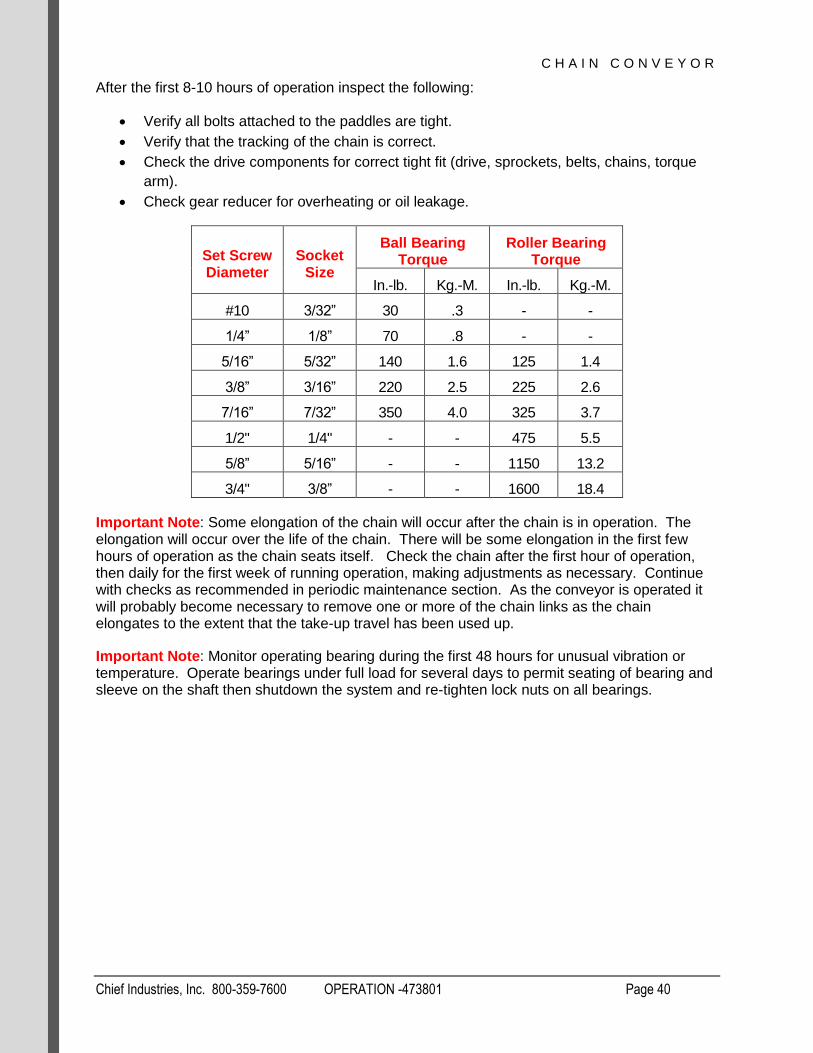
Set Screw Diameter
Socket Size
Ball Bearing Torque
Roller Bearing Torque
In.-lb. Kg.-M. In.-lb. Kg.-M.
#10 3/32” 30 .3 - -
1/4” 1/8” 70 .8 - -
5/16” 5/32” 140 1.6 125 1.4
3/8” 3/16” 220 2.5 225 2.6
7/16” 7/32” 350 4.0 325 3.7
1/2" 1/4" - - 475 5.5
5/8” 5/16” - - 1150 13.2
3/4" 3/8” - - 1600 18.4
Important Note: Some elongation of the chain will occur after the chain is in operation. The elongation will occur over the life of the chain. There will be some elongation in the first few hours of operation as the chain seats itself. Check the chain after the first hour of operation, then daily for the first week of running operation, making adjustments as necessary. Continue with checks as recommended in periodic maintenance section. As the conveyor is operated it will probably become necessary to remove one or more of the chain links as the chain elongates to the extent that the take-up travel has been used up.
Important Note: Monitor operating bearing during the first 48 hours for unusual vibration or temperature. Operate bearings under full load for several days to permit seating of bearing and sleeve on the shaft then shutdown the system and re-tighten lock nuts on all bearings.

C H A I N C O N V E Y O R
Chief Industries, Inc. 800-359-7600 OPERATION -473801 Page 41
Periodic Maintenance
The following are guidelines for maintaining the conveyor. Operators will have to determine what inspection and service intervals are necessary for their application. Factors to consider are the frequency of operation and the operating environment of the equipment.
1. Daily
a. Always be aware of the normal operating sounds. If any abnormal sounds occur,
stop the conveyor, find the source of the noise, then lock out power to conveyor
and repair the problem.
2. Weekly
a. Lubricate bearings according to manufacturer specifications.
3. Monthly
a. Check V-belt tension and overall condition. Replace if worn, frayed, or cracked.
b. Check that set screws in pulleys and bearings are tight. If necessary tighten to
manufacturers’ specifications.
c. Check for missing or damaged paddles. Replace if necessary. Check paddle
bolts for tightness. Check attachments to chain. If attachments are slightly bent
and do not appear to be in danger of separating from the chain and the
attachments are not having an adverse effect upon the capacity, replacement is
not necessary.
d. Check that the conveyor chain is properly tensioned and is tracking correctly.
e. Check oil level in gearbox and inspect seals for signs of leakage. Follow
manufacturer’s specifications for oil level and oil change periods.
f. Check that the motor is clean and properly ventilated.
g. Lubricate motor according to manufacturer’s specifications and intervals.
4. Quarterly
a. Check all conveyor components for loose or missing fasteners.
b. Check safety guards for interference with moving parts.

C H A I N C O N V E Y O R
Chief Industries, Inc. 800-359-7600 OPERATION -473801 Page 42
Troubleshooting
Items shown below are an aide to troubleshooting when a problem is encountered. Some causes can be corrected by reviewing certain areas of the assembly instructions. When checking conveyor capacities, note that rated capacities are calculated using 75% cup fill.
1. Problem: Measured capacity is reduced from the rated capacity
a. Possible cause: Incorrect shaft RPM
i. Possible reason or solution
1. Undersized reducer
2. Incorrect sheave orientation
b. Possible cause: Loose chain
i. Possible reason or solution
1. Incorrect chain speed
c. Possible cause: Incorrect feed
i. Possible reason or solution
1. Incorrect grain flow at inlet
d. Possible cause: Conveyor incline level
i. Possible reason or solution
1. 5% maximum incline level
e. Possible cause: Conveyor plugging
i. Possible reason or solution
1. Check and clear discharge opening
2. Problem: Noisy operation
a. Possible cause: Loose paddles
i. Possible reason or solution
1. Tighten or replace fasteners
b. Possible cause: Conveyor bottoms not aligned
i. Possible reason or solution
1. Check intermediate bottom joints and verify they are flush
c. Possible cause: Damaged chain attachments
i. Possible reason or solution
1. Replace attachments
d. Possible cause: Worn idler roller or rail return
i. Possible reason or solution
1. Replace components
e. Possible cause: Drive components
i. Possible reason or solution
1. Check oil level

C H A I N C O N V E Y O R
Chief Industries, Inc. 800-359-7600 OPERATION -473801 Page 43
3. Problem: Uneven paddle wear
a. Possible cause: Conveyor misalignment
i. Possible reason or solution
1. Align conveyor sections from head to tail
b. Possible cause: Sprocket slipped
i. Possible reason or solution
1. Check set screws on sprocket.
2. Center and square sprocket in opening and tighten set screws
4. Problem: Excessive carry-over of material
a. Possible cause: Chain riding over material
i. Possible reason or solution
1. Verify maximum incline is not above 5%
b. Possible cause: Gates not fully open
i. Possible reason or solution
1. Check gate operation
5. Problem: Uneven sprocket wear
a. Possible cause: Worn chain
i. Possible reason or solution
1. Replace chain
b. Possible cause: Incorrect sprocket alignment
i. Possible reason or solution
1. Center and square sprocket in opening and tighten set screws

C H A I N C O N V E Y O R
Chief Industries, Inc. 800-359-7600 MANUAL - 473801 Page 44
Manufacturer Data / Recommendations
The following pages have been provided to assist our customer during maintenance of components that have been factory installed on your Chief Elevator.
C H A I N C O N V E Y O R
Chief Industries, Inc. 800-359-7600 MANUAL - 473801 Page 45
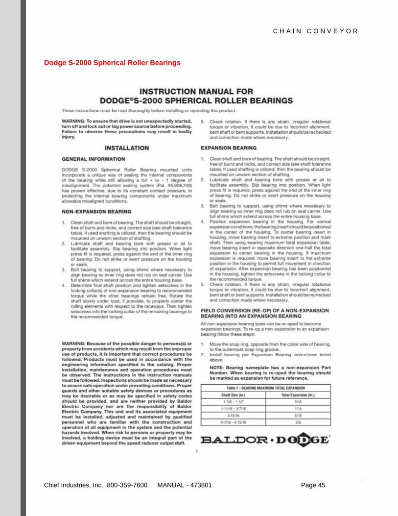
Dodge S-2000 Spherical Roller Bearings

C H A I N C O N V E Y O R
Chief Industries, Inc. 800-359-7600 MANUAL - 473801 Page 46

C H A I N C O N V E Y O R
Chief Industries, Inc. 800-359-7600 MANUAL - 473801 Page 47

C H A I N C O N V E Y O R
Chief Industries, Inc. 800-359-7600 MANUAL - 473801 Page 48

C H A I N C O N V E Y O R
Chief Industries, Inc. 800-359-7600 MANUAL - 473801 Page 49
Dodge Imperial and ISAF Bearings
C H A I N C O N V E Y O R
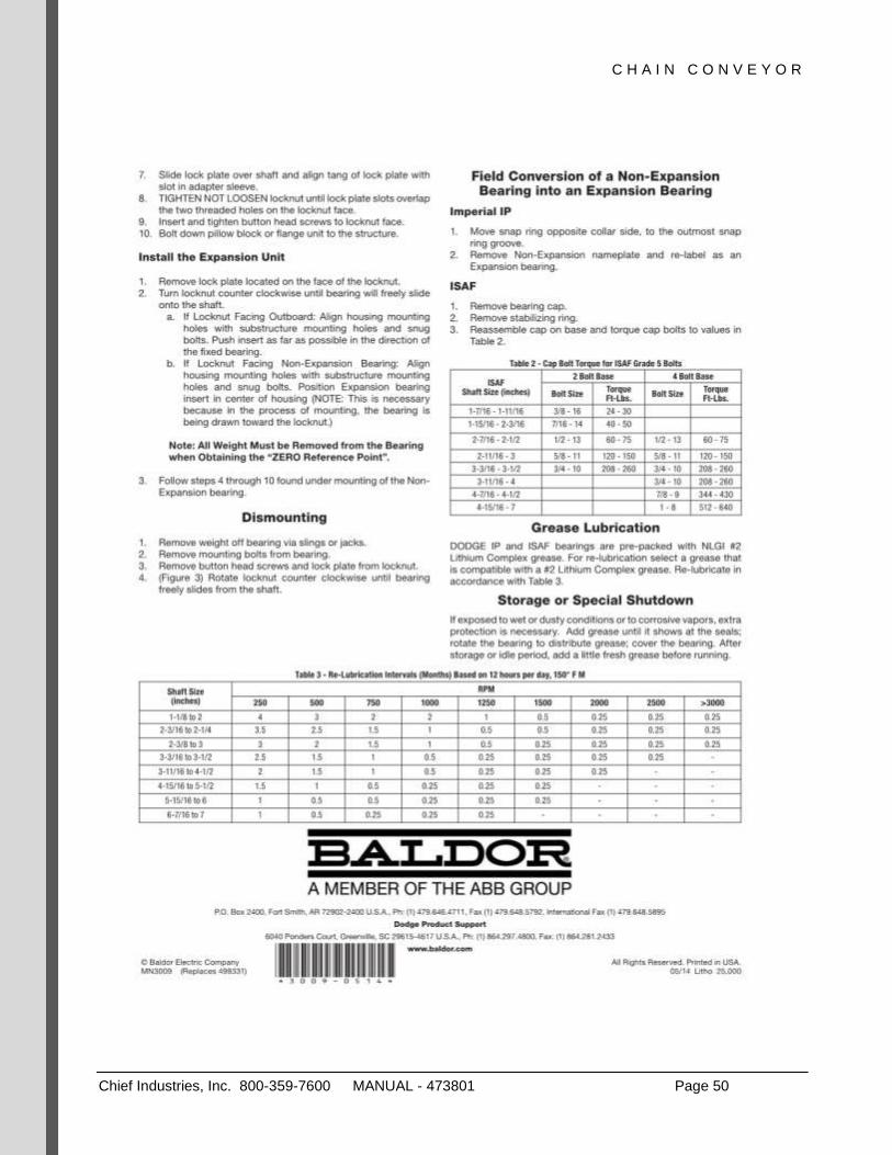
Chief Industries, Inc. 800-359-7600 MANUAL - 473801 Page 50
C H A I N C O N V E Y O R
Chief Industries, Inc. 800-359-7600 MANUAL - 473801 Page 51
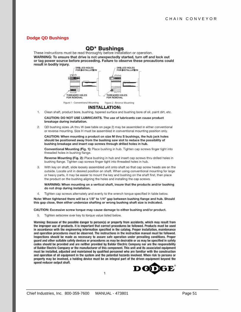
Dodge QD Bushings

C H A I N C O N V E Y O R
Chief Industries, Inc. 800-359-7600 MANUAL - 473801 Page 52

C H A I N C O N V E Y O R
Chief Industries, Inc. 800-359-7600 MANUAL - 473801 Page 53
Dodge XT Pulley Bushing

C H A I N C O N V E Y O R
Chief Industries, Inc. 800-359-7600 MANUAL - 473801 Page 54
C H A I N C O N V E Y O R
Chief Industries, Inc. 800-359-7600 MANUAL - 473801 Page 55
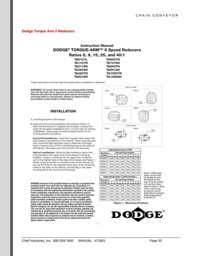
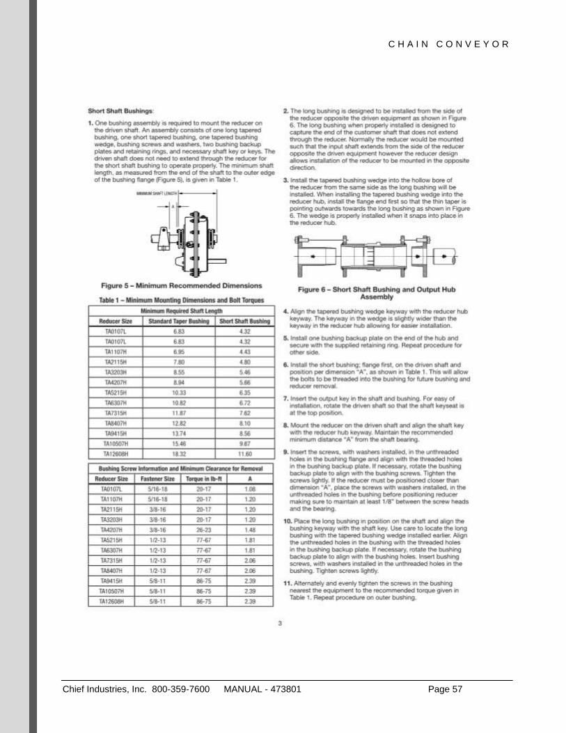
Dodge Torque Arm II Reducers

C H A I N C O N V E Y O R
Chief Industries, Inc. 800-359-7600 MANUAL - 473801 Page 56
C H A I N C O N V E Y O R
Chief Industries, Inc. 800-359-7600 MANUAL - 473801 Page 57

C H A I N C O N V E Y O R
Chief Industries, Inc. 800-359-7600 MANUAL - 473801 Page 58

C H A I N C O N V E Y O R
Chief Industries, Inc. 800-359-7600 MANUAL - 473801 Page 59

C H A I N C O N V E Y O R
Chief Industries, Inc. 800-359-7600 MANUAL - 473801 Page 60

C H A I N C O N V E Y O R
Chief Industries, Inc. 800-359-7600 MANUAL - 473801 Page 61
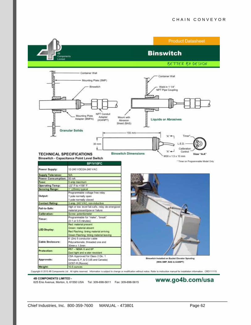
4B Level Indicator
C H A I N C O N V E Y O R
Chief Industries, Inc. 800-359-7600 MANUAL - 473801 Page 62

C H A I N C O N V E Y O R
Chief Industries, Inc. 800-359-7600 MANUAL - 473801 Page 63
4B Slip Indicator

C H A I N C O N V E Y O R
Chief Industries, Inc. 800-359-7600 MANUAL - 473801 Page 64

C H A I N C O N V E Y O R
Chief Industries, Inc. 800-359-7600 MANUAL - 473801 Page 65
4B Slip Indicator

C H A I N C O N V E Y O R
Chief Industries, Inc. 800-359-7600 MANUAL - 473801 Page 66

C H A I N C O N V E Y O R
Chief Industries, Inc. 800-359-7600 MANUAL - 473801 Page 67
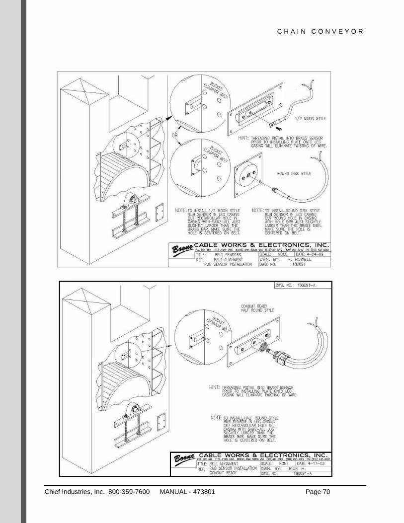
Rolfes Belt Alignment Indicator

C H A I N C O N V E Y O R
Chief Industries, Inc. 800-359-7600 MANUAL - 473801 Page 68

C H A I N C O N V E Y O R
Chief Industries, Inc. 800-359-7600 MANUAL - 473801 Page 69
C H A I N C O N V E Y O R
Chief Industries, Inc. 800-359-7600 MANUAL - 473801 Page 70

C H A I N C O N V E Y O R
Chief Industries, Inc. 800-359-7600 MANUAL - 473801 Page 71
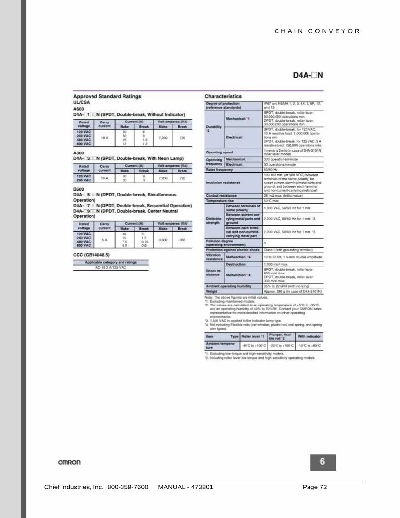
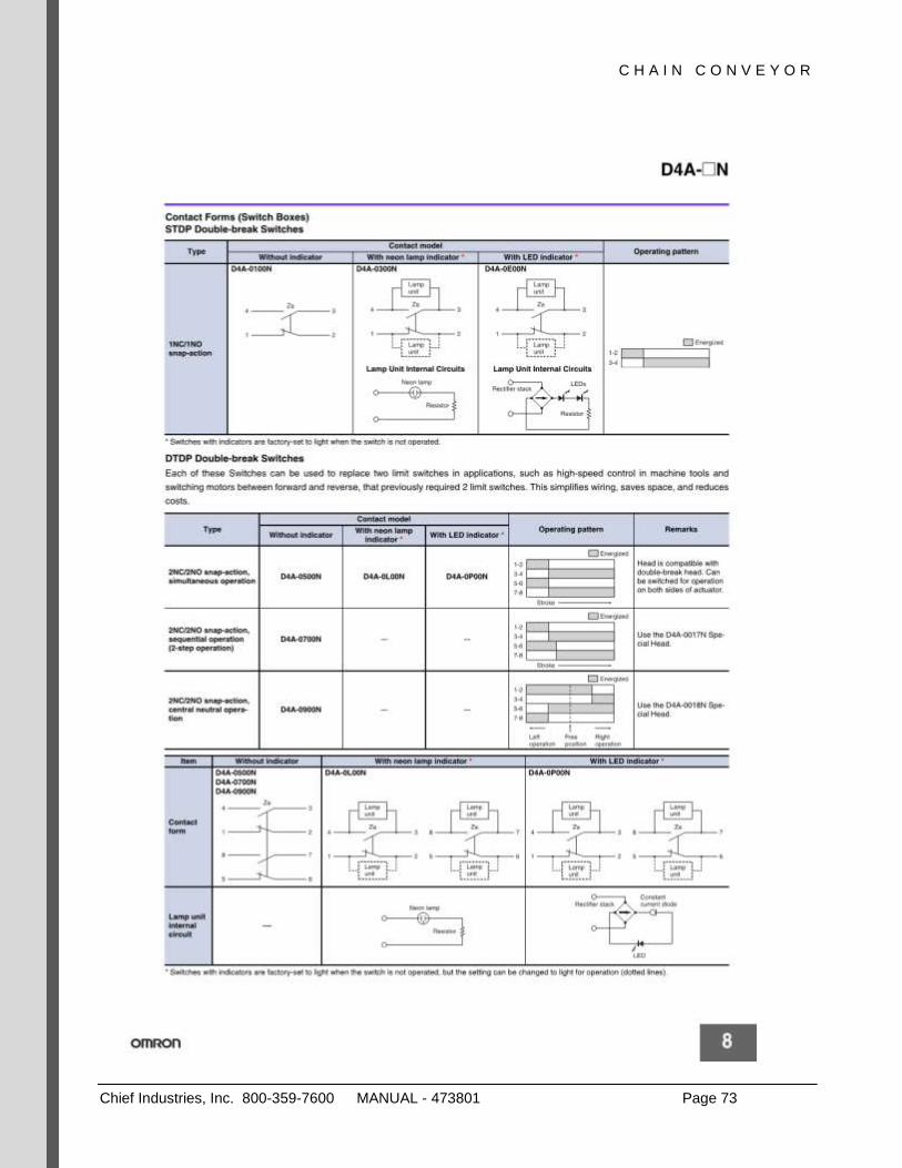
Omron Limit Switch
C H A I N C O N V E Y O R
Chief Industries, Inc. 800-359-7600 MANUAL - 473801 Page 72
C H A I N C O N V E Y O R
Chief Industries, Inc. 800-359-7600 MANUAL - 473801 Page 73

C H A I N C O N V E Y O R
Chief Industries, Inc. 800-359-7600 MANUAL - 473801 Page 74
C H A I N C O N V E Y O R
Chief Industries, Inc. 800-359-7600 MANUAL - 473801 Page 75
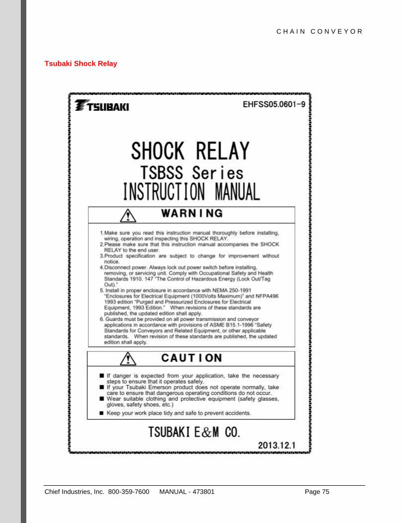
Tsubaki Shock Relay

C H A I N C O N V E Y O R
Chief Industries, Inc. 800-359-7600 MANUAL - 473801 Page 76

C H A I N C O N V E Y O R
Chief Industries, Inc. 800-359-7600 MANUAL - 473801 Page 77

C H A I N C O N V E Y O R
Chief Industries, Inc. 800-359-7600 MANUAL - 473801 Page 78

C H A I N C O N V E Y O R
Chief Industries, Inc. 800-359-7600 MANUAL - 473801 Page 79

C H A I N C O N V E Y O R
Chief Industries, Inc. 800-359-7600 MANUAL - 473801 Page 80

C H A I N C O N V E Y O R
Chief Industries, Inc. 800-359-7600 MANUAL - 473801 Page 81
C H A I N C O N V E Y O R
Chief Industries, Inc. 800-359-7600 MANUAL - 473801 Page 82

C H A I N C O N V E Y O R
Chief Industries, Inc. 800-359-7600 MANUAL - 473801 Page 83
Should you have any questions concerning assembly instructions, parts or drawings, please feel free to contact us at any of the following.
Chief Industries, Inc. Inc.
4400 East 39th Street • PO Box 848
Kearney, NE 68847
Phone 800.359.7600
For more information about Chief Industries, Inc. and additional products or services visit our website
www.agri.Chiefind.com