Embed Size (px)
Citation preview

_ -- _ -. - --
ch R
1st Edith Schject to errors and changes. WKD 423 220 3M 3/90 PI inted in Germany

928 S Models 85,86
rnEES ‘.
928 S4 ?E E )I( s -1.. :
h+B I,.. Models87,88, 89
i
- .
Tech- nical - Spec.if i- catjons
INTRODUCTION
We are publishing this booklet with information on
Models, Dimensions and Tolerances
to provide the Porsche mechanic with speci- fications necessary to render proper service.
We took into account that the mechanic is familiar with the service operations outlined in the workshop manual.
When using this booklet, also refer to the Service Information Bulletins since the data and specifications are subject to change without prior notice.
MODELS DIMENSIONS
TOLERANCES
928 S Model1 85, 86
928 S4 Model! 87, 88,89
’ I
1 st Edition Stand as of 1011989
-- .-._ -

4
Table of Contents Page
General
Important Conversation Factors and New Dimensioning Units . 7 Survey of Type Designation ................... 8 Eogine Number Codes as from Model 85 .......... 10 Chassis Number Codes ..................... 11 Engine Type Designations .................... 12 Transmission Number Codes as from Model 85 ........ 14 Transmission Type Designations ................ 14 Transmission Number Codes as from Model 88 ........ 15 Transmission Type Designations ................ I5
Engine and Clutch
Technical Data Type 928 S/928 S4, Engine Data as of Model 85...8 9 ....................... 16 Torque Specifications - Engine ................ .22 Tolerances and Wear Limits - Engine ............. .26 Crankshaft-Standard and Reconditioning Sizes ........ 30 Tightening Sequence Upper and Lower Crankcase sections . .31 Checking Pistons and Cylinder Bores ............. .32 Survey Pistons (Sizes, Weights and Compressions ....... 34 Pistons and Cylinder Marks .................. .35 Valve Dimensions, Reconditioning Valve Seats, Angles and Dimensions, Installed Length for Engine Type M28.21/22 .................... .36 Checking Valve Seat Wear Limit and Valve Guides (32-valve engines) ................... .37 Valve Seat Angles and Valve Sizes (32-valve engines) .... .38
Checking Installation Length of Valve Springs (32-valve engines) ................... 39 Machining Cylinder Head .................... 40 : Cylinder Head Installing ..................... 41 Camshaft Survey 42 ........ , ...............
Camshaft Survey Club Sport and GT Version ......... , 44 Checking Camshaft Setting (32-valve engines) ......... 45 Adjusting Camshaft Toothed Belt, Drive Belt Dimensions and Settings ........................... 46. Coolant Mixing Table and Cleaning Engine Oil System ..... 47 Engine Testing and Adjusting Values .............. 48 Machining Flywheel ....................... 50 Torque Specifications for Clutch ............. , .. 51 Clutch-General ........................ 52
Transmission
Torque Specifications for Manual Transmission, Gear Shift and Central Tube .................. 54 5 Speed Manual Transmission Type G28, General Data .... 56 Torque Specifications-Automatic Transmission ........ 58 4-Speed AutomaticTransmission A 28, General Data . . _ . . 61 Pressure Valves in Bar to Model 86 ............... 63 Pressure Valves in Bar as from Model 87 ............ 64 Gear Shift Points in km/h .................... 65
6
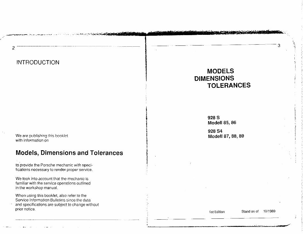
Front Axle, Steering and Rear Axle Page
Torque Specifications for Front Axle ...................... 66 Torque Specifications for Steering ........................ 68 Torque Specifications for Rear Axle ...................... 69 Technical Data - Front Axle, Steering andRearAxle ....................................... 71 Wheel Alignment Adjusting Values ....................... 72 Coil Springs for Adjustable Spring Struts (front axle) .......................................... 73
Brakes, Wheels and Tires
Torque Specifications for Mechanical Brake System .......... 74 Torque Specifications for Hydraulic Brake System ........... 76 Technical Data for Brake System ........................ 78 Rims, Tires and Tire Pressure ........................... 82
Electrical System
Location of Fuses and Relays ........................... 85
Air Conditioner
Technical Data - Air Conditioner ......................... 102 Torque Specifications - Air Conditioner .................... 103
General Technical Data
Dimensions ....................................... ..lO 4 Performance Figures .................................. 106 Weights .......................................... ..lO 8 Filling Capacities ..................................... 110
7 ‘\ i
Important Conversion Factors and New Dimensioning Units
Former Units Present Units
Pressure technical atmosphere Output Horsepower Force Kilopond Torque Kilopondmeter
Conversion Factors
at (kp/cm2) in bar
kp. in N
HP in kW
kpm in Nm m/s in km/h
at in mm Hg km/h in mph OF inoC itr. in U.S. gal Itr. in Imp. gal
at (kp/cm2) Bar (bar) HP Kilowatt (kW)
kp Newton (N)
Mm Newtonmeter (Nm)
.
x 0,981
x 9,81 x 0,736 x 9,81 x 3,6 x 735,56 x 0,621 (OF-32) x 0,555 x 0,264 x 0,22
To convert the tightening torque from kpm in Nm the conversion factor 10 can be used, which is sufficient for workshop applications.

8 - __ ._-. ~.. ----_-- --.. -___ ___- Survey of Type Designations
Model Vehicle Type Stroke/ Com- year Designation
Engine Dis- Engine Type place-Output Bore
Desig- A = Automatic pression
Desig- ment nation
(mm) Ratio nation (act.) DIN-kW(HP)
(cm3) at llmin E
1985 928 S Eur., R.o.W. M 28.21 4664 928 S Eur.. R.o.W. A M 28.22 228(310)/5900 78.9/97 10,4:1 4664 228(310)/5900 78.9197 10,4:1
928 S USA, CAN M 28.43 4957 928 S USA,Jap..CANA M 28.44 4957 215(292)/5750 78.9/100 10,O:l 215(292)5750 78.9/100 10,O:l
1986 928 S Eur..R.o.W. M28.21 4664 928 S Eur.. R.o.W. A M28.22 228(310)/5900 78.9197 10,4:1 4664 228(310)/5900 78.9/97 10,4:1
928SUSA M 28.43 4957 928SUSA,Jap. A M 28.44 4957 215(292)/5750 78.9/100 10,O:l 215(292)/5750
78.9/100 10,O:l
928 S AUS M-298i299 M 28.45 4957 928 S AUS M-2981299 A M 28.46 4957 212(288)/5750 78.9/100 9,3:1 212(288)/5750 78.9/l 00 9,3:1
928 S Sweden. CH M 28.21 4664 M 28.22 202(275)/5750 78.9197 928 S Sweden. CH A 9,3:1 4664 202(275)/5750 78.9197 9,3:1
1987 928S4 Eur..R.o.W. M 28.41 4957 928 54 Eur.. R.o.W. A M28.42 235(320)/6000 78.91100 10,O:l 4957 235(320)/6000 78.9/100 10,O:l
92854 USA M 28.41 4957 928 S4 USA A M 28.42 235(320)/6000 78.9/100 10,O:l 4957 235(320)/6000 78.9/l 00 10,O:l
928 S4 AUS M 28.41 4957 928S4 AUS A M 28.42 4957 221(300)/6000 78.9/l 00 10,O:l 221(300)/6000 78.9/100 10,O:l --___
1988 928S4R.o.W. M28.41 4957 928S4 R.o.W. A M 28.42 4957 235(320)/6000 78.91100 10,O:l 235(320)/6000 78.91100 10,O:l
928 S4 USA 928 S4 USA
928 54 AUS 928 54 AUS -- --- -.-
1989 928 S4 R.o.W. 928 S4 R.o.W.
928 54 USA 928 S4 USA
928 GT R.o.W. 928 GT USA
M28.41 4957 235(320)/6000 78.91100 A M28.42
10,O:l 4957 235(320)/6000 78.9/100 10,O:l
M 28.41 4957 78.9/100 A M 28.42
221(300)/6000 10,O:l 4957 221(300)/6000 78.91100 10,O:l -------~---
M 28.41 4957 78.9/100 A M28.42
235(320)/6000 10,O:l 4957 235(320)/6000 78.91100 10,O:l
M28.41 4957 A M28.42
235(320)/6000 78.9/100 10,O:l 4957 235(320)/6000 78.9/100 10,O:l
M 28.47 4957 243(330)/6200 78.9/100 10,O:l M28.47 4957 243(330)/6200 78.9llOO 10,O:l
Fuel system
B= unleaded
Engine Number Trans- Chassis Number Codes mission Codes
Type Sb= Premium grade-unleaded Sv= Premium grade-leaded
LH-Jetronic (Sv) 82FOOOOl-05000 G 28.10 WPO ZZZ 92 Z FS 84 0001-5000 LH-Jetronic (Sv) 82FO5001-10000 A28.05/06 WPO ZZZ 92 Z FS 84 0001-5000
LH-Jetronic (Sb) 81 FOOOOl -05000 G 28.11 xWPO JBO 92 - FS 86 0001-5000 LH-Jetronic (SbI 81 FO5001-10000 A 28.04 WPO ZZZ 92 - ZFS 84 9501-9999
LH-Jetronic (Sv) LH-Jetronic (Sv)
LH-Jetronic (Sb) LH-Jetronic (Sb)
LH-Jetronic (B) LH-Jetronic (B)
LH-Jetronic (8) LH-Jetronic (B)
82GOOOOl-05000 G 28.10 82605001-10000 A 28.08
8lG00001-05000 G28.11 81 G05001-10000 A 28.07
89GOOOOl-05000 G 28. IO 89G05001-10000 A 28.11
82GOOOOl-05000 G 28. IO 82605001-10000 A 28.09
LH-Jetronic (Sb) 8lH00001-01000 G 28.12 LH-Jetronic (Sb) 81H05001-10000 A28.14
LH-Jetronic (Sb) 81H00001-01000 G 28.13 LH-Jetronic (Sb) 81H05001-10000 A28.12
LH-Jetronic (B) 81HOOOOl-01000 G 28.12 LH-Jetronic (B) 8lH05001-10000 A28.14
WPOZZZ92ZGS840001-5000 WPOZZZ92ZGS840001-5000
WPOIBO92-GS860001-5000 WPOZZZ92ZGS849501-9999
WPOZZZ92ZGS840001-5000 WPOZZZ92ZGS840001-5000
WPOZZZ92ZGS840001-5000 WPOZZZ92ZGS840001-5000
WPOZZZ92ZHS840001-5000 WPOZZZ92ZHS 840001-5000
WPO JBO 92 - HS 86 0001-5000 WPO JBO 92 - HS 86 0001-5000
WPO ZZZ 92 Z HS 84 0001-5000 WPO ZZZ 92 Z HS 84 0001-5000
I I
LH-Jetronic (Sb) 8 1 JO0001 -05000 G 28.12 WPO ZZZ 92 Z JS 84 0001-5000 LH-Jetronic (Sb) 81 JO5001 -10000 A 28.14 WPO ZZZ 92 Z JS 84 0001-5000
LH-Jetronic (Sb) 81 JOOOOI-05000 G 28.13 WPO JBO 92 - JS 86 0001-5000 LH-Jetronic (Sb) 81 JO5001 -10000 A 28.12 WPO JBO 92 - JS 86 0001-5000
LH-Jetronic (B) 81 JO0001 -05000 G 28.12 WPO ZZZ 92 Z JS 84 0001-5000 LH-Jetronic (BI 81 JO5001 -10000 A 28.14 WPO ZZZ 92 Z JS 84 0001-5000
LH-Jetronic (Sb) 81 KOOOOI -05000 G 28.12 WPO ZZZ 92 Z KS 84 0001-5000 LH-Jetronic (Sb) 81 K05001-10000 A 28.16 WPO ZZZ 92 Z KS 84 0001-5000
LH-Jetronic (Sb) 81 KOOOOl-05000 G 28.12 WPO JBO 92 - KS 86 0001-5000 LH-Jetronic (Sb) 81 K05001-10000 A 28.16 WPO JBO 92 - KS 86 0001-5000
LH-Jetronic (Sb) 85KOOOOl-10000 G 28.55 WPO ZZZ 92 Z KS 84 0001-5000 LH-Jetronic (Sb) 85KOOOOl- 10000 G 28.55 WPO JE?O 92 - KS 86 0001-5000

Engine Number Codes from Model1 85
Explanation of digits:
1
T Engine Number Engine type Model Year Serial Number
8 = 8 cyl. engine
8 = 8 cyl. engine
8 = 8 cyl. engine
8 = 8 cyl. engine
8 = 8 cyl. engine
2 = 928/4,7 Itr. R.o.W. F= 1985 1 = 92815,O Itr. USA
1 = 928&O Itr. USA G = 1986 2 = 928/4,7 Itr. R.o.W.
1 = 928/5,0 Itr. worldwide H = 1987
1 = 928/5,0 Itr. worldwide J = 1988
1 = 928/5,0 Itr. worldwide K = 1989
5 = 928/5,0 Itr. GT worldwide
00001...99999
00001...99999
00001...99999
00001...99999
00001...99999
2
T 45678
I
Chassis Number Codes (Model 88)
WPO 222 92 2 J S 8 4 0001-5000
WPO ZZZ 92 Z J S 8 4 9501-9999
WPO JAO 92 - J S 8 6 0001-5000 -- -
Europe/Rest of world
Japan
USA/Canada
Serial number
Code for body and engine
3rd digit of type
Place of production
Model year (F = 1985, G = 1986, H=1987,J=1988,K=1989)
Test code
1 st and 2nd digit of type
VDS-Code USA
World manufacturer code

Engine Type Designation
Mfg. Year
_-- Model- Type Displ. Engine Fuel Installed in A = Automatic Year Desig- (cm31 output System Cars for
nation act. DIN (kW/HP)
1984185 1985 M 28.21 4664 228(310) LH-Jetronic 928 S Europe, R.o.W. M 28.22 4664 228(310) LH-Jetronic 928 S Europe, R.o.W. A
M 28.43 4957 215(292) LH-Jetronic 928 S USA, Canada M 28.44 4957 215(292) LH-Jetronic 928 S USA, Japan, Canada A
-
1985J86 1986 M 28.21 4664 228(310) LH-Jetronic 928 S Europe, R.o.W. M 28.22 4664 228(310) LH-Jetronic 928 S Europe, R.o.W. A
M 28.43 4957 215(292) LH-Jetronic 928 s USA M 28.44 4957 215(292) LH-Jetronic 928 S USA, Japan A
M 28.45 4957 ?I 2(288) LH-Jetronic 928 S Austr. M-298/299 M 28.46 4957 212(288) LH-Jetronic 928 S Austr. M-2981299 A
M 28.21 4664 202(275) LH-Jetronic 928 S Sweden, Switzerland M 28.22 4664 202(275) LH-Jetronic 928 S Sweden, Switzerland A
1986187 1987 M 28.41 4957 235(320) LH-Jetronic 928 S4 worldwide M 28.42 4957 235(320) LH-Jetronic 928 S4 worldwide A
M 28.41 4957 221(300) LH-Jetronic 928 S4 Australia M 28.42 4957 221(300) LH-Jetronic 928 S4 Australia A
1987188 1988 M 28.41 4957 235(320) LH-Jetronic 928 S 4 worldwide M 28.42 4957 235(320) LH-Jetronic 928 S4 worldwide A
M 28.41 4957 221(300) LH-Jetronic 928 S4 Australia M 28.42 4957 221(300) LH-Jetronic 928 S4 Australia A
i 988189 1989 M 28.41 4957 235(320) LH-Jetronic 928 S4 worldwide M 28.42 4957 235(320) LH-Jetronic 928 S4 worldwide A M 28.47 4957 243(330) LH-Jetr,onic 928 GT worldwide

f 14 -- ___-- ~- 1
i
Transmission Number Codes as from Model 85 a 1 1 1 F 00001 i
Transmission Number Codes as from Model 88
G2812
-7-i --ty
Transm. Type Index for variants Model year Serial within the assembly number Number
7- --T- --1- -r [ Engine Code 1 = transm. for 8-cyl. Engine
Transmission Type Model year Serial 1 = 5-speed man. F= 1985 Number
f
6 = Autom. transm. G = 1986 j
H = 1987
Note: The number 12 preceding the transmission number means that the transmission is fitted with a limited slip differential (40 %).
i
0 = no differential 1 = normal differential 2 = ZF limited slip
differential (M 220)
J = 1988 K = 1989
Attention: The transmission nos. 1 . ..I 00 and nos. 301...400 of each type have been reserved for experimental transmissions and for special-purpose transmis- sions, respectively. The first consecutive production no. is 501 Example: G 2812 2 J 10864 Transmission G 28 for R.o.W. applications with differential lock, manufactured for 1988 model year as 364th production transmission (with differential lock).
Transmission Type Designations
Trans- Number Installed installed Remarks mission of in car as from type speeds type transm.
number Transmission Type Designations
Trans-. Number installed Installed as mission of speeds in car from transm.
Remarks Mod. 85
code ____-- -___
G 28.10 G 28.11 A 28.04 A 28.05 A 28.06
Mod. 86 G 28.10 G 28.11 A 28.07 A 28.08 A 28.09
928 S 928 S 928 S 928 S 928 S
11 FOOOOI Manual transmission, Europe, R.o.W. 11 FO5001 Manual transmission. USA 16FOOOOl Automatic, USA! Japan 16FO5001 Automatic, Europe, R.o.W. (14:33) 16FlOOOl Automatic, Europe, R.o.W. (13:33)
type number code
928 S4 928 S4 928 S4 928 S4 928 S4 928 S4 928 S4 928 S4
G 2812 1 J 00001 G28122J 10001 G 2813 1 J 00001 G 2813 2 J 10001 A 2812 1 J 00001 A28122JlOOOi A28141JOOOO1 A 2814 2 J 10001
type Mod. 88 G 28.12 G 28.12 G 28.13 G 28.13 A 28.12 A 28.12 A28.14 A28.14
Manual transm., R.o.W. Manual transm., R.o.W. Manual transm., USA Manual transm., USA Automatic, USA Automatic, USA Automatic, R.o.W. Automatic, R.o.W.
Mod. 89 G 28.12 G 28.12 A 28.16 A28.16 G 28.55
: (M 220) 5 5 (M 220) 4 4 (M 220)
:: (M 220)
928 S 928 S 928 S 928 S 928 S
1 lGOOOOl Manual transmission, Europe, R.o.W. 11 GO5001 Manual transmission, USA 16GOOOOl Automatic, USA, Japan 16G05001 Automatic, Europe, R.o.W. (14:33) 16G10001 Automatic, Schweden,
Switzerland (13:33) 16G 15001 Automatic, Australia, R.d. W. Manual transm., worldwide
Manual transm., worldwide Automatic, worldwide Automatic, worldwide Manual transm., Club Sport, worldwide
G 2812 1 K 00001 G 2812 2 K 00001 A 2816 1 K 00001 A 2816 2 K 00001 G 2855 2 K 00001
A 28.11 928 S 5 5 (M 220) 4 4 (M 220) 5 (M 220)
928 S4 928 S4 928 S4 928 S4 928 S4
Mod. 87 G 28.12 G 28.13 A 28.12 A 28.14
928 S4 11 HO0001 Manual transmission, Europe, R.o.W. 928 S4 11 HO5001 Manual transmission, USA 928 S4 16HOOOOl Automatic, USA 928 S4 16HlOOOi Automatic. Europe, R.o.W. G 28.55 5 (M 220) 928 GT G 2855 2 K 00001 Manual transm., worldwide

Technical Data - Type 928 S/928 54 Engine Data from Model 85...89
Model Year
Engine Type
Engine
No. of cylinders
Bore mm/in. Stroke mm/in. Displacement (actual) cm3iin.3 Displacement (rounded down) cm3 Compression ratio
Max. engine power 8011269lEWG kW/HP
(Net Power, SAE J 1349) kWiHP At engine speed rpm Max. liter output
80/l 269iEWG Nm/kpm
(Net Torque, SAE J 1349) Nmilb ft At engine speed rpm
85186 928 S M 28.21122
8
97.0(3.82)
78,9(3,11)
4664(284.60
4632
10.4:1
2281310
85186 928 S M 28.43144
8
100 (3,94)
78.9(3,11)
4957(302,5
4898
10,O:l
215(288) 5750
410142
410 (302) 2700
86 928 S M 28.45146
---_
8
100 (3,94)
78,9 (3.11)
4957(302,5)
4898
9,3:1
2121288
400/40,8
2700
87...89 89 928S4 928 GT M 28.41142 M 28.47
8
100 (3.94)
7i3,9(3,11)
4957(302.5)
4898
10,o:i
2351320 Austr. 2211300 235 (316) 6000
430143,9 420/42,8 430(316,9) 3000
8
100 (3,94)
78.9 (3,111
4957(302.5)
4898
10,O:l
2431330
6200
Max. specific power DIN 70020 kW/L/HPIL
(SAE J 1349)
Fuel octane rating
kW/UHP/l
RON
Fuel cut-off to limit engine
speed at rpm Idle speed rpm Engine weight (dry) kg
Note: USA values in brackets.
49167
98 premium grade
6400
700+50
261
43,0(58,2)
96 unleadec
6400
680+20
264
42,8/58,1
91 unleaded
6400
680+20
264
47,4/6+6 44,6160,5
47,4(63,7)
95 unleaded 9
6600
675+25
264
49,0166,6
95 unleaded
6800
775+25
264

18
Technical Data Type 928 S Engine Type M 28.21/22 (4,71)
Engine Design Design
Crankcase
Crankshaft Connecting rods Pistons
Camsh&
Camshaft drive Cylinder head Arrangement of valves Valve timing
Valve play
8 cylinder, four stroke, internal combustion V-Engine Two-piece, light alloy cylinder/crankcase, without liners Forged with 5 plain bearings Sinter-forged steel Cast light alloy with chrome or iron plated bearing surfaces Cast, running in camshaft housing without bearing shells Toothed belt with tightening roller Light alloy 1 intake, 1 exhaust in line overhead By overhead camshaft and hydraulic bucket tappets Automatic (hydraulic) adjustment
Timing (1 mm stroke, zero play)
Engine Cooling
Intake opens 6’ after TDC Intake closes 54’ after BDC Exhaust opens 43~ before BDC Exhaust closes 4’ before TDC
Closed coolant-filled system, mechanical fan with visco-clutch (when air conditioner is installed as extra equipment, with extra electric fan and thermal switch)
Engine Lubrication
Oil filter Oil pressure at 4000/min
Oil pressure indicators Oil consumption I/l 000 km
Forced oil circulation system with crescent pump Full flow type approx. 5 bar for oil temp., between 80...100 OC Indicator lamp and pressure gauge approx. 1,5
Exhaust System Continuous twin pipes, primary, intermediate and final mufflers
Emission control Secondary air injection
Technical DataType 928 S Engine type M 28.21/22 (4,71)
Heater Warm water heater with heat exchanger and blower
Fuel system
Fuel delivery Fuel Grade RON Fuel Consumption constant 90 km/h l/100 km constant 120 km/h l/l 00 km ECcity cicle l/i 00 km 19.2
LH-Jetronic
1 electric fuel delivery pump 98 Manual Automatic
8.7 8.6 10.2 10.5 16.7
Electrical System Shielding class Battery voltage Battery capacitance Ih Alternator/output A/W Ignition Firing order Ignition timing EZF
Spark splugs Spark plug mm electrode gap
Power Transmission
Clutch
Pressure plate MFZ 200
ECE-R 10 und 72/245/EWG
Ag (72 as from Mod. 86) 115/1610 by EZF breakerless I-3-7-2-6-5-4-8 by
Bosch WR 7 DC 0,7 + 0,l
Engine mounted at front end, trans- mission mounted at rear end, both connected by a connecting pipe - trans- axle system. Front mounted engine, clutch, torsional elastic drive shaft to transmission running in connecting tube, rear mounted transmission with final drive, double joint shafts, rear wheels
Two plate, dry clutch with diaphragm springs in pulled versions, located on engine end

Tolerances and Wear Limits - Engine
Engine type M 28.21 I22 When in- stalled (new)
Wear Limits
Engine type M 28.43/44/45/46l41 I42147 When in- Wear stalled (new) Limits
Valve guide/valve stem Intake Exhaust Compression
clearance
Pistons and Connecting Rods Cylinder/piston clearance
Piston rings Side Nut 1 clearance
Nut 2
Nut 3
Piston rings end gap
0.80 0.80 0.80 0.80
8 bar and above 6.5 bar 8 bar and above 6.5 bar
0.024...0.048 app.0.080
Mahle KS. 0.06... 0.05...
0.102 0.082 0.04... 0.05... 0.072 0.082 0.013... 0.023... 0.127 0.137
Nut 1 = 0.20...0.40 Nut 2 = 0.20...0.40 Nut 3 = 0.40...1.40
0.008...0.032 app. 0.080
Mahle K.S. 0.05... 0.04...
0.082 0.072 0.04... 0.02... 0.072 0.072 0.036...0.036... 0.136 0.136
Nut 1 =0.20...0.40 Nut 2 =0.20...0.40 Nut 3 =0.40...0.90
Conrod bushing dia.
Piston pin dia.
Conrod bushing/piston pin radial play
Crankshaft and Engine Block
Crankshaft runout (measured on 2nd, 3rd or 4th bearing, bearings 1 and 5 on v-blocks)
Conrod bearing journal dia.
Conrod bearing/crankshaft radial play axial play
Crankshaft bearing journal dia.
Crankshaft bearing/ crankshaft radial play
Crankshaft bearing/ crankshaft axial play
Cylinder bore out of rue
24 +0,018
+0.028
24 -0.004
o.oia...o.o32
0.04
51.971...51.990
0.034...0.092 0.100...0.400
69.971...69.990
0.020...0.098
0.110...0.312
0.010
24 +O.OI a
+0.028
24 -0.004
0.018...0.032
max. 0.06 0.04
51.971...51.990
0.027...0.069 0.08...0.24
69.971...69.990
0.16 0.028...0.070
0.40 0.06...0.192
0.020 0.010
max. 0.06
0.16

Tolerances and Wear Limits - Engine
Engine type M 28.21/22 When in- Wear stalled (new) Limits
Engine type M 28.43l44l45/46l41 I42147 When in- Wear stalled (new) Limits
- Cooling System Coolant thermostat Cap for cooling system Pressure valve Vacuum valve
Oil circuit System Oil consumption
Oil pressure at 80% oil temperature Oil dipstick Oil volume Amount of oil between Oil pump
Valve Timing
Bore dia. for camshaft
opens at temperature 81...8!?‘C 81...85%
opens at 0.9...1.15 bar 0.9...1.15bar opens at 0.07...0.12 bar 0.07...0:12 bar
Itr./lOOO km up to approx. 1.5
at 4000/min approx. 5 bar
min.-max.- axial play radial play
7.5 Itr. 1.5 Itr. 0.080...0.120 0.060...0.088
60.5 +0.03
-0 28
+0.021
-0
up to approx. 1.5
at 3000imin approx. 5 bar
7.5 Itr. 1.5 Itr. 0.080...0.120 0.060...0.088
.*
Camshaft dia.
Camshaft axial play
Bore dia. for bucket tappet
Bucket tappet dia.
Camshaft runout
Cylinder Head and Valves Bearing surface distortion Valve seat Intake width Exhaust width Intake Seat angle Exhaust Seat angle Outer correction angle Inner correction angle Valve guides Intake and Exhaust dia. Valve stem dia.: Intake dia. Exhaust dia.
605 -0.03
-0.045
Q.09...0.12
38 +O.OlO
-0.038
38 -0.018
-0.034
0.02
max. 0.03
1.7 2.0 45’ l
45’ 30” 60”
9 +0.015
8.97 -0.012 8.95 -0.012
0.20 0.08...0.18
35 +0.015
-0.005
35 -0.025
-0.041
0.02
max. 0.03
1.5 1.8 45’ 45’
60”
7 +0.015
6.97 -0.012 6.94 -0.012
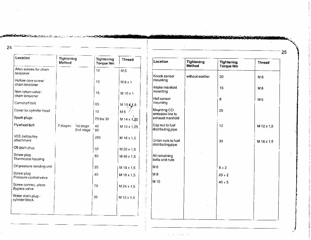
Location
Alien screws for chain tensioner
Hollow-core screw/ chain tensioner
Non-return valve/ chain tensioner
Camshaft bolt
Cover for cylinder head
Spark plugs
Flywheel bolt
VEE-belt pulley attachment
3il drain plug
Screw plug Thermostat housing
3il pressure sending unit
Screw plug ‘ressure control valve
jcrew connec. piece 3ypass valve
tiater drain plug - :ylinder block
Tightening Method
! stages: 1 st stage 2nd stage
10 M6
10 M8xl
15 MlOxl
65
IO
25 bis 30
10 30
?95
MlO$ 5 Jy t. >
M 6 .;:.-
M 14x1:25
M 10 x I.,25
W 18x 1,5
lil2ox 1,5
vl48 x 1.5
VI 18x 1,5
4 18x I,5
A 24 x I,5
bl12x 1.5
Tightening Torque Nm
- -
Thread Location
Knock sensor mounting
Intake manifold mounting
Hall sensor mounting
Mounting CO smission line to axhaust manifold
Zap nut to fuel distributing pipe
Jnion nuts to fuel distributing pipe
911 remaining loIts and nuts
W6
vl8
VllO
Tightening Tightening Met hod Torque Nm
Thread
without washer 20 M8
15 M8
8 M6
25
12
30 M 16x 1,5
8+2
20 + 2
40 + 5
M 12x 1,5

Torque Specifications - Engine M 28.21/22143/44/45146141/42/47
Location
Vlain bearing bolt
Main bearing bolt
Tightening Tightening Method Torque Nm
3 stages: 1 st stage 30 2nd stage 55 3rd stage 75 + 5
2 stages: 1 st stage 20 2nd stage / 50 + 5
Thread
M 12x I,5
M IO
3il pump bolt 2 stages: 1 st stage 15 2nd stage 20
M8
;onrod nut with ribbed surface
75 M 10 x I,25
Zyiinder head bolt with stud bolt ___.
Torquing angle tightening method:
1 st stage 20 2nd stage 90’ torquing angle 3rd stage 90’ torquing angle 4th stage 90’ torquing angle
Cylinder head bolt 1 st stage 20 with hexagon nti 2nd stage 90‘ torquing angle
3rd stage 90’ torquing angle
Camshaft bearing 10 M6 bridges to cylinder head 20 M8
Camshaft housing to 20 M8 cylinder head
Screw plug to camshaft lousing
40 M 18x 1,5
9 F 23
Location Tightening Tightening Thread Method Torque Nm
Water drain plug 175 M IO *adiator
p a. Screw socket on radiator 70 on engine 70
Oil hose to screw socket 70 M 26x 1,5 on upper section of crankcase
on radiator
Temperature switch radiator
Thermostat housing for cooling circuit to engine
Remote thermometer sending unit-Water temperature
Non-return valve
Air line
Oxygen sensor
Screw plug exhaust removal at catalytic converter
70 M 26 x I,5
40
2 stages: 1 st stage IO M8 2nd stage 20 + 2
25 - 30
55
30
55 M 18x I,5
15 M8xl
Temperature sensor NTC II to thermostat housing
12

G
Technical Data Type 928 S/928 S4 (32-Ventiler 50 I>
Changes (values) in model year 85/86 Engine type M 28.43144145146 ,
Arrangements of valves 2 intake, 2 exhaust. overhead V
Valve timing
Camshaft drive
2 overhead camshafts per cylinder bank
Toothed belt and internal chain
Timing (1 mm stroke, zero play)
Exhaust System
Intake opens 11’ after TDC Intake closes 50” after BDC Exhaust opens 30” before BDC Exhaust closes 5” before TDC
Twin pipes entire length 3-way catalytic converter, twin pipes in final muffler
Emission Control 3-way catalytic converter, secondary air injection
Changes (values) in model year 87/88/89 Engine type M 28.41/42/47
Connecting rods
Arrangements of valves
Stahl, gegossen oder sintergeschmiedet
2 Input, 2 Output, overhead V
Valve timing
Camshaft drive
Timing (1 mm stroke, zero play)
. 2 overhead camshafts per cylinder bank
Toothed belt and internal chain
Blower drive
Ignition timing
Clutch
Input opens 11’ after TDC (3”) Input closes 36” after BDC (42”) Exhaust opens 17” before BDC (30” Exhaust closes 2” before TDC (5”)
Double electric fan
EZK breakerless
Single-plate dry clutch with diaphragm spring, extended mounted on engine
Pressure plate GMFZ 250
(Club Sport
‘) and GT)
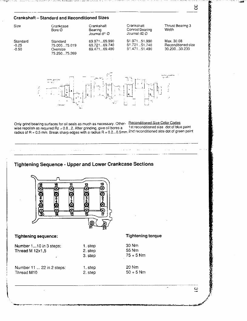
Crankshaft-Standard and Reconditioned Sizes
Size
Standard -0.25 -0.50
Crankcase Bore 0
Standard 75.000...75.019 Oversize 75.250...75.269
Crankshaft Bearing Journal dl 0
69.971...69.990 69.721...69.740 69.471...69.490
Crankshaft Conrod Bearing Journal d2 D
51.971...51.990 51.721...51.740 51.471...51.490
Thrust Bearing 3 Width
Max. 30.08 Reconditioned size 30.200...30.239
Only grind bearing surfaces for oil seals as much as necessary. Other- Reconditioned size Cofor Codes wise repolish as required Rz = 0.8...2. After grinding, give oil bores a 1 st reconditioned size dot of blue paint radius of R = 0.5 mm. Break sharp edges with a radius R = 0.2...0.5mm. 2nd reconditioned size dot of green paint
Tightening Sequence - Upper and Lower Crankcase Sections
Tightening sequence:
Number 1 . ..lO in 3 steps: 1. step Thread M 12x1,5 2. step
. 3. step
Number 11 . . . 22 in 2 steps: 1. step Thread Ml 0 2. step
Tightening torque
30 Nm 55 Nm 75+5Nm
20 Nm 50 + 5 Nm

* ,: /: ‘,_ ::
shaft - Staridard
, ;;;kpy ., -. -:::. y”’ --’ ’ Crqhk$yft :‘;.I. ‘, : Crankshaft. ’ * Bearing ?,+,.: ,: ‘. Cotyod Bearing ,’ ’ , &yl;i B@ng 3 ” ‘,, .’
’ I . . + Journalcil 0 _ Jouyald20 , . ‘_ .. * r: ._ ,
. rd , Standard
75.000...75.019 I . ’ 69.9f;...69.990 ’ . 51.!&.51.d~0 : ,Max. 30.08 69.721...69.740”, 51.721...51.740 Reconditioned size ’ I
Oversize 69.471 w69.490 51.471.,.51.490 30.200...30.239 75.250...75.269 “ ,*

Checking Piston Checking Cylinder Bores
Measure about 62 mm from piston crown. offset to piston pin axis by
Measure about 62 mm from cylinder bore
90”. upper edge, transverse to engine block. Note: To measure, install crankcase lower section and tighten to specified torque.
Engine Type M 28.21122
_____ .-__- Size Piston Dia. (mm) Cylinder Bore Dia.
Mahle Tolerance Group
(mm) Code -
Standard 96,965 97.000 0 96,975 + 0.005 97,010 + 0,005 1 96,985 97,020 2
1 St oversize 97,465 97.500 0 KD 1 97,475 * 0.005 97,510 + 0,005 1 KD 1 97,485 97,520 2KDl
.__ 2nd oversize 97.965 98.000 OKD2
97,975 * 0.005 98.010 * 0,005 1 KD2 97,985 98,020 2KD2
Only pair pistons and cylinders of the same tolerance group.
Different tolerance groups could be used in one engine.
Checking Pistons and Cylinder Bores (32 valves)
Engine Type M 28.43144/45146
Size Piston Dia. (mm) Kolben- Schmidt
Cylinder Bore Dia. (mm)
Tolerance Group Code
Standard 99,975 100,000 0 99,985 M,007 100,010 lro,oo5 1 99,995 100,020 2
1 st Oversize 100,475 1 O&500 1 0 I 00,485 +0,007 100,510 *0,005 1 1 100,495 100,520 1 2
Engine Type M 28.41142/47
Size Piston Dia. (mm) Kolben- Schmidt
Cylinder Bore Dia. (mm)
Tolerance Group Code
Standard 99,980 100,000 0 99,990 HI,007 100,010 f0,005 1 100,000 100,020 2
1 st Oversize i 00,480 100,500 1 0 100,490 +0,007 100,510,0,005 1 1 100,500 100,520 1 2
Only pair pistons and cylinders of the same tolerance group. Different tolerance groups could be used in one engine.
i .

34 -_____ _---. I -.--. - ---.. ___--- 35
Piston Allocation (Sizes, Weights and Compressions) Pistons and Cylinder Codes
Engine M 28.21122
Europe and Rest of World Compression 10,4:1 Nominal Dia. 97 mm
Engine M 28.21122
Sweden, Switzerland Compression 9,3:1 Nominal Dia. 97 mm
Code for piston on piston crown
Piston Weight = 722 g, Permissible tolerance = rt: 4 g
(32-Ventiler)
Engine M 28.43144 Engine M 28.45146
USA, Canada und Japan Compression 1 O.O:l Nominal Dia. 100.0 mm
Austr. M-298/299 Compression 9,3:1 Nominal Dia. 100.0 mm
Cylinder Codes (Numbers)
Motor M 28,41142/47
worldwide Compression 10,O:l Nominal Dia. 100.0 mm
Piston weight = 765 g Permissible tolerance = F 4 g
Piston WeightsTolerances
Pistons and piston pins are paired in accordance with weight selection. Piston weighed with parts (piston pin, piston rings, flap rings).
Piston pins must always remain assigned to the corresponding piston and must not be interchanged even within one engine set. Observe allocation during dissembly and assembly of engine, mark if necessary.
If piston pins have been interchanged by mistake, reallocation must be carried out by chec!$ng the total weight.
Firing Order 1-3-7-2-6-5-4-8
Code for cylinder on engine block
a - Cylinder code (location) b - Tolerance group
Notes for Installing Pistons (32~valve engines)
The “AV -‘I (exhaust valve) inscribed on the base of the piston indicates the installation position (arrow toward exhaust side).
The valve cutouts for the valves are of equal size on both sides. The installation position is indicated by an arrow which points toward the belt pulley.
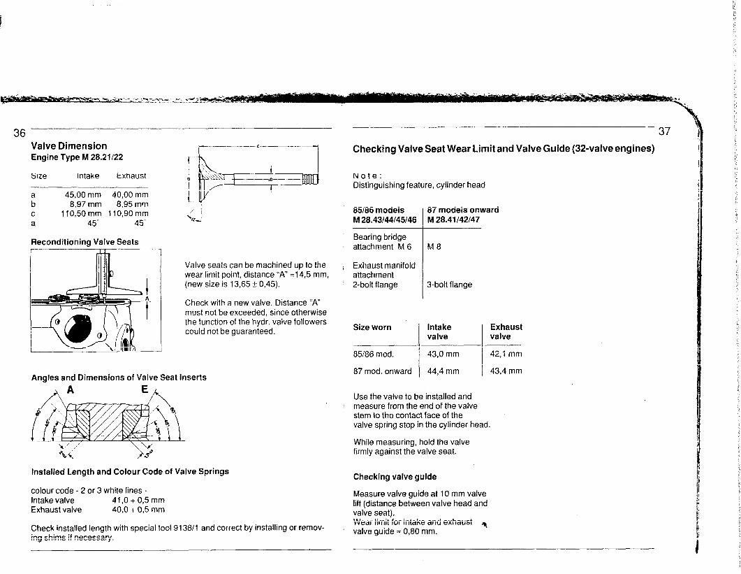
Checking Valve Seat Wear Limit and Valve Guide (32~valve engines)
Note: Distinguishing feature, cylinder head
36 Valve Dimension Engine Type M 28.21122
Size intake Exhaust
r--- __- c------...-
1
Fl 45,00 mm 40,OO mm
8,97 mm 8,95 mm c 1 lo,50 mm 1 lo,90 mm a 45' 45'
85/86 models M 28.43/44145/46
,’ ’ ‘Li
87 models onward M 28.41 I42147
Bearing bridge attachment M 6
Valve seats can be machined up to the i Exhaust manifold wear limit point, distance “A” =14,5 mm, attachment (new size is 13,65 rt 0,45). 2-bolt flange
Reconditioning Valve Seats
3-bolt flange
Intake valve
43,0 mm
44,4 mm
Check with a new valve. Distance “A” must not be exceeded, since otherwise the function of the hydr. valve followers could not be guaranteed. Size worn
85186 mod.
87 mod. onward Angles and Dimensions of Valve Seat inserts
Use the valve to be installed and measure from the end of the valve stem to the contact face of the valve spring stop in the cylinder head.
While measuring, hold the valve firmly against the valve seat.
8
i
Installed Length and Colour Code of Valve Springs
colour code - 2 or 3 white lines - Intake valve 41,O + 0,5 mm Exhaust valve 40,O + 0,5 mm
Checking valve guide
Measure valve guide at IO mm valve lift (distance between valve head and valve seat). Wear limit for intake and exhaust 31
’ valve guide = 0,80 mm. Check installed length with special tool 913811 and correct by installing or remov- ing shims if necessary.

‘2Q -- __.- ___ 39
Valve Seat Angle and Valve Dimensions (3%valve engines) Checking and Adjusting Installation Length of Valve Springs (32~valve engines)
Valve Seat Angle
Valve Dimensions 928 S
Mod. 85186 onward
Motortyp M 28.43i44145146
Rim- a b C (I.
JJ make__ 35,OOmm
6.97mm 112.20mm
45”
Valve Dimensions
ExbausL 32,OOmm
6,94mm 111.20mm
45O
Intake-valve face width 1.5 mm
Exhaust-valve face width 1.8 mm
Valve Dimensions 928 S4
Valve springs 85 models onward Valve springs 86 models onward Engine Type M 28.43144 Engine Type M 28.45146
Check length of intake-valve Check length of intake-valve and exhaust-valve springs and exhaust-valve springs with special tool 9240. with special tool 9240/l.
Intake 42,6 + O,5 mm Intake 39,7 + 0‘5 mm Exhaust 41,6 + 0,5 mm Exhaust 38,7 + 0,5 mm
Checking Installation Length of Valve Springs with Depth Gage
Note: Using a depth gage, measure from surface of valve spring plate through gap to outer spring bearing surface.
Mod. 87 onward
Motortyp M 28.41142147
-ExhausL 33,OOmm
6,94mm 113,70mm
45O
Nr. M28.46 89G 05072 Engine type M28.41/42147
installation Length Installation Length Intake 37,0 + 0,5 mm Intake 35,5 + 0,5 mm Exhaust 36,0 + 0,5 mm Exhaust 34,5 + 0,5 mm
Note: Valve surinq Mod. 85 Mod. 86/87/88l89 It is essential to ensure that the correct valve springs are installed in cars of the various model years. Free length
Outer spring 40,O mm 43,5 mm
Wire dia. Outer spring 4,l mm 3,6 mm
. Inner spring 2,9 mm 2,7 mm

Machining Cylinder-Head Mating Face
Permissible roughness of mating face: 0,03 mm Max. depth of material removed: 0.2 mm peak-to-valley height = 0,015 mm
Motortyp M 28.21122
Size new A = 24 + 0,l Size worn A = 23,8
Engine type M 28.43/44/45!46/41142/47
Size new A = 147 + 0,l Size wornA = 146,8
Installing Cylinder Head (32~valve engines and M 28.21122) Cylinder head attached by means of t-m&
Installing Cylinder Head Torquing sequence (4 steps) see Fig. Sequence for removal: reverse
1 st step 20 Nm 2nd step 90” of rotation 3rd step 9O’of rotation 4th step 9O’of rotation
Installing Cylinder Head (32~valve engines) Hexa- cylinder-head bolts
Note The cylinder head can also be in- stalled with the engine in place. If both cylinder heads are to be removed and installed, it is advisable to remove the engine first.
Torquing sequence (3 steps) Sequence for removal: reverse 1 st step 20 Nm 2nd step . 90’ of rotation 3rd step 90’ of rotation
Note As a rule, do not use lubricant when installing the cylinder-head nuts or
Mod. 89 qnward new cylinder head screws
hex bolts and washers, It is only necessary to apply a light
new screw length 20 mm longer M12xl99
coat of engine oil to the stud bolts M12x149 or hex bolts.

Camshaft installation
Model year
Engine type
Camshaft, right
Cylinder bank I...4
Intake shaft
Exhaust shaft
Identification code on
the rear end face
Camshaft, left
Cylinder bank 5...8
Intake shaft
Exhaust shaft
Identification code on
the rear end face
Mod. 85186
928 S
M 28.21122
928.105.211 .OO
211 .oo
928.105.212.00
212.00
Mod. 85186
928 S (32-valve eng
M Z&43/44145/46
928.105.291.04 928.105.291.09 928.105271 .OO
928.105.293.04 928.105.293.09 928.105.273.00
291.04 291.09 271.00
293.04 293.09 273.00
928.105.292.04 928.105.292.09
928.105.294.02 928.105.294.08
292.04 292.09
294.02 294.08
Mod. 87 _-- ._
928 S4
M 28.41i42 ~.~_
Mod. 88...89
928 S4
M 28.41142
928.105.272.00
928.105.274.00 I
272.00
274.00
_---
Valve timing,
1 mm stroke, zero play
Intake opens 6” CS after TDC 11’ CS after TDC 11” CS after TDC 11’ CS after TDC
Intake closes 54” CS after BDC 50” CS after BDC 36” CS after BDC 36” CS after BDC
Exhaust opens 43” CS before BDC 30” CS before BDC 17” CS before BDC 17’ CS before BDC
Exhaust closes 4” CS before TDC 5” CS before TDC. 2” CS before TDC 2’ CS before TDC
Note
The camshafts of 87 und 88...89 models may be combined for installation.

44
Camshaft Installation Club Sport and GT-Version
Model Year
Engine Typ
Camshaft right Cylinder bank 1...4 Intake shaft Exhaust shaft
Identification code on the rear end face
Camshaft left Cylinder bank 5...8 Intake shaft Exhaust shaft
Identification code on the rear end face
Valve timing. 1 mm stroke, zero play
intake o P
ens Intake c oses Exhaust o ens Exhaust c oses P
Note:
Mod. 88
928 S4 M 28.41 Club Sport
928.105.291.06or 928.105.293.06 or
291.06 293.06
928.105.292.06 or 928.105.294.05 or
292.06 294.05
3’ KW after O.T. 42. KW after U.T. 30’ KW bef. U.T.
5’ KW bef. O.T.
Mod.89
928 GT M 28.47
928.105.271 .Oi 928.105.273.01
271 .Ol 273.01
928.105.272.01 928.105.274.01
272.01 274.01
3” KW after O.T. 42’ KW after U.T. 30’ KW bef. U.T.
5. KW bef. O.T.
Both types of camshafts may be combined for installation.
46 -~-----
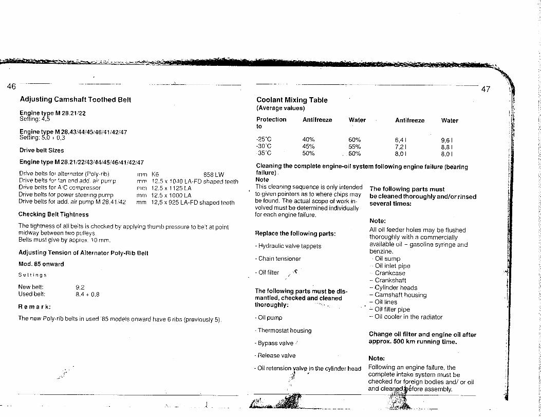
Adjusting Camshaft Toothed Belt
Engine ty e M 28.21122 Setting: 4, !
Engine t pe M 28.43144!45146141142147 Setting: ,O + 63 r
Drive belt Sizes
Engine type M 28.21122/43/44145146/41142147
Drive belts for alternator (Poly-rib) mm K6 858 LW Drive belts for fan and add. air pump mm Drive belts for AC compressor
12.5 x 1040 LA-FD shaped teeth mm 12,5x 1125LA
Drive belts for power steering pump mm 12.5 x 1000 LA Drive belts for add. air pump M 28.41142 mm 12.5 x 925 LA-FD shaped teeth
Checking Belt Tightness
The tightness of all belts is checked by applying thumb pressure to belt at point midway between two pulleys. Belts must give by approx. 10 mm.
Adjusting Tension of Alternator Poly-Rib Belt
Mod. 85 onward
Settings
New belt: 9.2 Used belt: 8.4 + 0.8
Remark:
The new Poly-rib belts in used ‘85 models onward have 6 ribs (previously 5).
,:i .
.) -
_.. _ --
Coolant Mixing Table (Average values)
Protection Antifreeze t0
Water Antifreeze Water
-25°C 40% 60% 6,4l 9,6 I -30°C 45% 55% 7,2 I 8,8 I -35°C 50% 50% 870 I 8,0 I
Cleaning the complete.engine-oil system following engine failure (bearing failure) Note
’ This cleaning sequence is only intended to given pointers as to where chips may be found. The actual scope of work in- volved must be determined individually for each engine failure.
Replace the following parts:
- Hydraulic valve tappets
- Chain tensioner
- Oil filter c i .I
The following parts must be dis- mantled, checked and cleaned thoroughly: “ml. __
- Oil pump
- Thermostat housing
- Bypass valve ,’
- Reiease valve
- Oil retension valve in the cvlinder head
The following parts must be cleaned thoroughly and/or rinsed several times:
Note:
All oil feeder holes may be flushed thoroughly with a commercially available oi! - gasoline syringe and benzine. - Oil sump - Oil inlet pipe - Crankcase - Crankshaft -Cylinder heads - Camshaft housing - Oil lines - Oil filler pipe - Oil cooler in the radiator
Change oil filter and engine oil after approx. 500 km running time.
Note:
Following an engine failure, the complete intake system must be checked for foreiqn bodies and/ or oil , -
assembly.

& ----__ -.
Testing and Adjusting Specifications
T t
t
T I t
! , I
i
Mod. 8586 M 28.43/44145146
Specifications
Mod. 87...89 M 28.41142
- --__
Specifications
T T ! f
Mod. 89 M 28147
Specifications
____
at least 1350 cm”i30s
at least 1250 cm3/30s
at least 1250 cm3130
2.5 t 0.2 bar 3,8 + 0.2 bar 3,8 i- 0,2 bar
approx. 2,0 bar approx. 3,3 bar approx. 3,3 bar
1,O bar 3.0 bar 3.0 bar
1
Mod. 85’86 M 28.21122
Model year Engine type -
Test Point Specifications
Electrrc fuel
pump Delivery rate
Fuel pressure
(engine stopped)
Fuel pump relay
bridged
Chec value for
idle
Leak test
Min. pressure after
20 Min.
at least 1350 cm”!30s
2.5 20.2 bar
approx. 2.0 bar
1 .O bar
without with without with without with
cata lytic converter catalytic converter catalytic converter Idle setting
Idle speed
(rpm)
CO level %
700 f 50
0,5...1,5
0,5...1 ,o Australia, Switzerland, Sweden
680 + 20
0,6 zk 0,2”
HC-levels ppm 1300 2300
775 IL 253’ 775 f 253’
0,5...1,5 0,4...1,22’3’
675 zk 253’ 675 _+ 253’
0,5...1,5 0,4...1 p3)
5300 5300 5300 2300
‘) Oxygen sensor plug disconnected
*) Oxygen sensor plug connected
3, not adjustable

50 ---- El
Torque Specifications for Clutch dl
Machining Flywheel
Engine type M 28.21143145
The bearing surface for the drive plate on the flywheel can be ma- chined in a lathe when seriously scored or burnt.
The metal removal should be kept as small as possible. Wear limit 27.5 mm Max. runout 0.05 mm
Bearing surface machining specifications: Surface finish + waviness = 0,008 mm
Wear limit 27.5 mm
Location Nm Wpm)
Description Thread Material Torque
Ring gear - Bolt M7xl 8.8 15 intermediate ring
Guide tube clutchitrans- mission
Bolt M6xl 8.8 IO
Clutch slave cylinder
Bolt M 8 x I,25 8.8 23
Clamp/ Clamping bolt M 10x 1,5 12,9 80 central shaft I and II
Clutch housing/ Bolt M 10x I,5 8.8 45 central tube
Engine/clutch Bolt housing
Clutch housing/ Bolt cover
M 12x I,5 8.8 85
M8x I,25 8.8 23
Clutch/ Bolt flywheel (Socket head bolt)
M 8 x I,25 8.8 23

‘..A:.... ? ‘_^_ -1) “,‘.. ..’ ,I ,..’ “.... .I :. Gl’ ru
Clutch
Engine type M 28.21143145
Design Two plate, dry clutch with pulled version diaphragm springs, located on engine side, hydraulic operation.
Pressure plate MFZ 200
Contact pressure 5600...6200 N
Clutch disk 200 0 (flywheel end)
Clutch disk 200 0 (flywheel end)
Clutch disk lateral 0.4 mm at 190 0 runout
Clutch play at clutch pedal*
approx. 3 mm
Engine type M 28.41/47
Design Single-plate dry clutch with diaphragm spring, extended, mounted on engine hydraulic operation
Pressure plate GMFZ.250
Contact pressure 9900...11100 N
Clutch disk 0 250
Nehmerzylinder Kolben
0 22,2 mm (before 23,8 mm)
* The clutch play cannot be checked at the clutch pedal because of the automatic hydraulic adjustment.
On the other hand perfect function of the clutch must be guaranteed by having a play of 0.5 mm between the push rod and master cylinder piston.
This play cannot be measured; it must be determined on the clutch pedal by sense of feeling. On the pedal tread plate it will be about 3 mm.

Torque Specifications for Manual Transmission, Gear Shift, Central Tube
Location
Central tube/transmission
Locknut,’ Drive pinion
Bearing covet-i Transmission case
Plug/Lock
Upper cover Transmission case Reverse gear deflector/ upper cover
Ring gear bolt Side cover/ Transmission case
Rear cover/ Transmission case
Oil filler and drain plug
l- I T
Description
Hexagon bolt
Locknut
Hexagon bolt
Screw plug
Hexagon bolt
Hexagon bolt
Hexagon bolt Hexagon bolt
Hexagon bolt
Screw plug
Thread Material
M 10x 1.5
M32x1.5
M 8 x 1.25
M 12x 1.5
M6xl
M6xl
M 12x 1.25 M 8 x 1.25
M 8 x 1.25
M 24 x 1.5
I- 10.9
10.9
5.8 20
8.8 10 12.9 16 8.8 10
12.9 8.8
a.8
T I-
-___- Tightening Torque NITI
58
300
30
165 22
22
22
.,-
Clamping sleeve/ input shaft
Backup light switch
Joing flange/output Transmission
Bearing unit/inner shift rod
Transmission mount/ Transmission case
Central tube/ Clutch housing
Shift rod/Bearing unit (Shift rod clutch)
Angle joint/ Guide tube
Bearing bracket for guide tube to body or central tube
Cap and Hexagon nut on stud for preselector spring
Clamping bolt M 10x I,5 12.9 80
Backup light switch
Hexagon bolt
M iax 1,5 22
M 10x1,5 8.8
8.8
8.8
8.8
43
Conical bolt M 8 x I,25 15
Hexagon bolt M 12x I,5 a5
Hexagon bolt M 10x 1,5 43
Hexagon bolt M a x 1,25 25
Hexagon nut BM IO
Hexagon nut M6xl
Cap and Hexagon nut
M14xl
25
10
50

S-Speed-Manual Transmission Type G 28
Type Equipment
G 28110 5 speed G 28/l 1 5 speed G 28/l 2 5 speed G 28/I 3 5 speed G 28155’ 5 speed
‘limited slip differential fitted as standard (40%)
installed in: Model Year -
928 S Eur.0Xo.W. 1985186 928 S USA 1985186 928 S4 Eur./R.o.W. 1987188 928 S4 USA/Japan 1987188 928 S4 Club Sport ww 1988 928 GT ww 1989
S-Speed-Manual Transmission Type G 28 General Manual Transmission Manual Transmission
Data Typ G 28.10112/55 Typ G 28.11113
Design Direct transmission with iayshaft Ratios’ Zl 22 iz iiay iz x ilay Zi z2 iZ ilay iz x ilay
zz:z1 32:22 z2:zt 33:21
1. gear 17 44 2,5882 1,4545 3,7645 17 44 2,5882 1,5714 4,0672
2. gear 22 38 1,7272 1,4545 2,5122 22 38 I,7272 I,5714 2,7142
3. gear 26 32 1,2307 I,4545 I,7900 26 32 I,2307 1,5714 1,9339
4. gear 29 27 0,931o I,4545 1,3541 29 27 0,931o 1,5714 1,4629
5. gear direct 1 ,oooo direct 1 ,oooo direct 1 ,oooo direct 1 ,oooo
R.-gear 22 (30) 2,2727 1,4545 3,3056 22 (30) 2,2727 I,5714 3,5714
(30) 50 (30) 50
Final drive Drive pinion without hypoid displacement
Final drive ratio II:30 i = 2,7272 (G 28.1 O/55) 15:33 i = 2,200 11:29 i = 2,6363 (G 28/l 2)
Transmission oil Multi-grade gear lube SAE 75 W 90
API-classification GL.5 (or MIL-L 2105 B)
Oil capacities 85 models and earlier = approx. 3,8 liters
86 models onward = approx. 4,5 Liter
* Zt = Number of teeth on first gear wheel in the load path of the gear concerned
ZZ = Number of teeth on second gear wheel in the load path of the gear concerned
iz = Gear ratio
ivOr = Layshaft ratio

Torque Specifications for htoniatic Transmission Torque Specifications for Automatic Transmission
rhread 1 lghtening t orque (Nm)
Location Descrlptlon 1 Vlaterial
Socket head bolt M5 5.8 4
Bolt M6 8.8 8
Screw plug
Bolt
M8xl 13
M6 8.8 8
Solenoid valve M14xl ,5 20
-
-- T t I.- 2
hread M iS3al
18 8.8
ightening- orque (Nm) _____ 0
110x1 10.9 4
18 8.8 3
16 10.9 1
4 27 x 1 .F
A6
70
8.8 3
v16 8.8 8
ti6 8.8 8
M6
M6
M6
8.8 8
8.8 8
8 6
_---- GSiGii ____. -.-~ ----. ‘rimary pump to .ont cover
icrew plug Converter)
Bolt
‘rant cover to Bolt ,ansmission case i
Lower cover with reinforcement plate
Lower cover, assembly to trans- mission case
Screw plug (Test point modulating, governor, operating pressure)
Bolt (Bracket vacuum socket)
Kick-docvn solenoid valve
End cover to valve body
End plate to pick-up case
Pick-up case to valve body
Valve body to transmission
ATF filter to lower cover
Socket head bolt M4 8.8 3,3
Socket head bolt M4 8.8 3,3
Socket head bolt. M5 4.8 0,15
Bolt M6 8
Bolt M5
8.8
8.8 4
-
;upport flange to Bolt ransmission case
;crew plug Brakeband B 1)
Screw plug 1
;atch plate to -ange selector ;haf!
/Bolt
-eaf spring to Hexagon transmission case bolt
Anti-restart and Bolt backup light switch to transmission case
Range selector lever Hexagon to shaft bolt
Secondary pump to ;;:agon transmission case
Nut. shaft axial Hexagon mounting. governor nut
-

60 Torque Specifications for Automatic Transmission
I Location
~_ Description
Screw plug (ATF pan)
_____ Screw plug
ATF pan to Hexagon transmission case bolt
Front converter housing to trans- mission case
Socket head bolt
Driver plate to converter
Hexagon bolt
Rear converter housing to trans- mission case
Socket head bolt
Bearing unit to rear transmission case
Socket head bolt
Final drive to trans- mission case
Hexagon bolt Hexagon nut
Collar nut (Drive pinion)
ATF filler tube to ATF pan
ATF tank to ATF pan
Collar nut
Coupling nut
Socket head bolt
Thread
MlOxl
M8
M8
M 10
M8
M IO
M 10
M 26 x 1 ,E
M 24
M6
rlaterial
8.8
8
8.8
‘ightening orque (Nm)
14
8
23
Type Equipment
A 28104 4 speed
A 28105 4 speed
A 28106 4 speed
46
42 A 28107
A 28108
33 A 28/09
46
46
380
78
A 28/I 1 4 speed 928 S Australia, 1986 M-298/299
A 28/I 2 4 speed 928 54 USA 1987188
A 28/l 4 4 speed 928 S4 Europe/R.o.W. 1987188
A 28/I 6 4 speed 928 S4 worldwide 1989
6
61
4-Speed-Automatic Transmission A 28
installed in Model Year
928 S USA/Japan 1985
928 S Europe0Xo.W. 1985 rear axle transm. ratio 14:33
928 S Europe/R.o.W. 1985 rear axle transm. ratio 13:33
4 speed 928 S USA/Japan 1986
4 speed 928 S Europe1R.o.W. 1986 rear axle transm. ratio 14:33
4 speed 928 S Europe/R.o.W. 1986 rear axle transm. ratio 13:33

4-Speed-Automatic Transmission A 28 Pressure Values in Bar until Model ‘86
_____ Test pressure
Zeneral Data A 28.04!07/12 j A28.05Q6108:09/11/14~16 l___- Transm. Tyy A 26.04/O,?
Measuring instructions Transm. Type A 28.05/06108/ 09/I 1 Fully automatic 4-speed sun-and-olanet transmission ----_------ -.-~-- __ ----i-
3esign _ ~_-. -_-~. --~.--- - ~-
Ratios ATF temp. approx. 8O‘C, Selector lever in pos. ..D”, driving speed approx. 140 km/h, vacuum line disconnected at modulating pressure cell.
A 28.04iO5:06!07!08i 09:11/12/14
A 28.16
3.6760 3.87 2.3120 2.25 f .43FO 1.44 1 .QOOO I ,oo 5.1390 5:59
Modulating pressure’
4,o + 0,05
1 st gear 2nd gear 3rd gear 4th gear Reverse gear
ATF temp. approx. 80-C, Selector lever in pos. .,D”, engine running at idle speed, vacuum line dis- connected at modulating pressure cell.
Operating pressure
16,9 + 1 15.3 + 1 J- Finat drive f?r!ve pinion without hypoid displacement
.~ __.__ ~-- .- .---.~--. -T- ---- 15:33 i-2.200
11114i16)
A 28.04107 = A 28.05iO6/08109~11 = 1650...2050 l;min 2200...2600 l:mln
Final drive catio i
I
_____
Governor pressure
at 20 km/h at 50 km/h at 100 kmih at 150 km/h
approx. 0,2 approx. I ,I approx. 2,O approx. I,7
Sel&tor lever in pos. .,D”, vehicle rolls in partial load range, vacuum line disconnected at modulating pressure cell.
approx. 0,2 approx. I,1 approx. 2,0 approx. 2,7
Stall speed
L
! A 28.12 = A 28.14116 = 1750...2150 I;min , 1750...2150 l/min
-----
approx. 2.7 I(‘87 models onward, approx. 3.0 I hypoid transmission oil.) API classification GL5 (MIL L 2105 6) SAE 90
____
Total capacity = approx. 8.0 I (‘87 models onward, approx. 9.3 I). Capacjty for fluid change with conver& = approx. 6,O I(‘87 models onward, approx. 7,3 I) ATF - Dexron II D
Capacity. rear axle final drive
Cpacity, autom. unit with converter
‘Note
If local constraints preclude testing the car at approx. 140 km/h (88 mph), meas- urements may be carried out at approx. 50 km/h (31 mph).
-.-- _-._. - __._ /
-. -. -.
64 _-
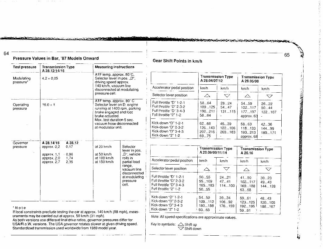
Pressure Values in Bar, ‘87 Models Onward 65
Gear Shift Points in km/h
Test pressure rransmission Type ~28.12l14116
1,2 + 0.05
Measuring instructions
Modulating pressure*
4TF temp. approx. 8O”C, Selector lever in DOS. ..D”. driving speed approx.” 140 km/h, vacuum line disconnected at modulating oressure cell. /
Transmission Type A 28.04107/l 2
Transmission Type A 28.05108
km/h km/h ---_
n v ---- 54...59 26...22 102...1 17 50...44 177...197 122...107 approx. 63 -
62...68 45...39 58...63 42...36 126...143 122...106 118...133 144...99 207...216 203...183 193...213 189...171 69...75 - approx. 68 -
Accelerator pedal position
Selector lever position
Full throttle “D” 1-2-l Full throttle “D” 2-3-2 Full throttle “D” 3-4-3 Full throttle “2” I-2
Kick-down “D” 1-2-i Kick-down “D” 2-3-2 Kick-down “D” 3-4-3 Kick-down “2” l-2
4TF temp. approx. 80’ C Selector lever on D, engine unning at 1400 rpm, parking I >rake engaged and foot ,rake actuated. / flax. test duration 5 sec. vacuum hose disconnected St modulator unit.
Operating pressure
16.0 + 1
__- 4 28.14/16 A 28.12 approx. 0,2 0,ii
Governor pressure st 20 km/h
at 50 km/h at 100 km/h 31150 km/h
Selector lever in pos. ,,D”, vehicle rolls in partial load range, vacuum line disconnected at modulating pressure cell.
Transmission Type A 28.06/09/l i/14
Transmission Type A 28.16
spprox. i,t 0,96 approx. 2,0 I,74 spprox. 2,7 2,35
I Accelerator pedal position km/h km/h km/h
Selector lever position n v n I
, Full throttle “D” 1-2-l 50...55 24...21 41...50 30...23 49...43 144...128
Kick-down “D” 1-2-l Kick-down “D” 2-3-2 Kick-down “D” i 3-4-3 180...188 176...159 192...195 Kick-down “2” 1-2 60...65 - 59...61 ‘Note
If local constraints preclude testing the car at approx. 140 km/h (88 mph), meas- urements may be carried out at approx. 50 km/h (31 mph). As both versions use different final drive ratios, governor pressures differ for USAIFi.o.W. versions. The USA governor rotates slower at given driving speed. Standardized transmission used worldwide from 1989 model year.
Note: All speed specifications are approximate values.
Key to symbols: L1 Shift up V Shift down
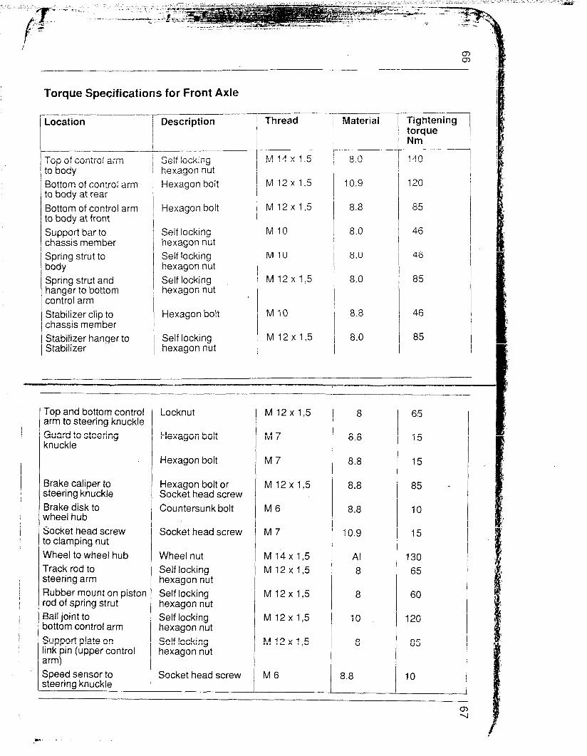
Torque Specifications for Front Axle
Location
Top of control arm to body Bottom of control arm to body at rear Bottom of control arm to body at front Support bar to chassis member Spring strut to body Spring strut and hanger to bottom control arm Stabilizer clip to chassis member Stabilizer hanger to Stabilizer
Description Thread
Self locking hexagon nut Hexagon bolt
Hexagon bolt
Self locking hexagon nut Self locking hexagon nut Self locking hexagon nut
Hexagon bolt
Self locking hexagon nut
M14x1,5
M 12x 1.5
M 12 x 15
M 10
M 10
M 12x 1.5
Ml0
M 12x1,5
-- Material Tightening
torque Nm
8.0 140
10.9 120
8.8 85
8.0 46
8.0 46
8.0 85
8.8 46
8.0 85
--
Top and bottom control arm to steering knuckle Guard to steering knuckle
Brake caliper to steering knuckle Brake disk to wheel.hub Socket head screw to clamping nut Wheel to wheel hub Track rod to steering arm Rubber mount on piston rod of spring strut Ball joint to oottom control arm Support plate on ink pin (upper control arm) Speed sensor to steering knuckle
Locknut
Hexagon bolt
Hexagon bolt
Hexagon bolt or Socket head screw Countersunk bolt
Socket head screw
Wheel nut Self locking hexagon nut Self locking hexagon nut Self locking hexagon nut Self locking hexagon nut
Socket head screw
M 12x 1,5 8 65
M7 8.8 15
M7 8.8 15
M 12x 15 8.8 85
M6 8.8 10
M7 10.9 15
M 14x 1,5 Al 130 M 12 x 1,5 8 65
M 12x 1,5 8 60
M 12x 1,5 10 120
M 12x1,5 8 85
M6 1 8.8 10

68 rorque Specifications for Steering
-0cation
Steering gear to Zngine mount
Track rod to ;teering arm
Jniversai joint to steering gear
rrack rod to Iall joint
Tie rod to steering .ack
Jniversal joints to ;teering shaft and dler arm
Delivery and return iine to steering gear
Steering wheel to steering shaft
Stabilizer clip to chassis member
V-belt pulley to power steering pump Steering guard to body
Hose nipple of in- take hose to power steering pump
Iescription
Self locking iexagon nut
Self locking iexagon nut
Self locking lexagon nut
iexagon nut
Tie rod
Self locking ‘iexagon nut
Hollow bolt M 14 x 1.5
Hexagon nut
Hexagon bolt M IO 8.8
Self locking hexagon nut
Socket head bolt
Hollow bolt M 18x I,5 c 35
1 I I
rhread
--- bl IO
bl 12x I,5
V8
bl 14 x I$5
‘.416x I,5
M 18x 1.5
bl 14x 1.5
M 6 with 4 mm socke M 6 with 5mm socket
Material
5
a
8
04
16MnCr5
a
8
8
Ightening orque dm
46
65
28
45 .
28
30
50
46
50
9,7
12
60
Torque Specifications for Rear Axle
Location
Cross member to body
Light alloy casting (suspension link bearing) for lower control arm 86 mod. onward) to body
Lower control arm to cross member (camber eccentric)
Lower control arm to body (track eccentric)
Brake caliper to wheel carrier
hheel member to lower control arm
Upper control arm ta cross member, uppe control arm to wheel member
Drive shaft and rear wheel shaft to wheei hub
Drive shaft to trans- mission and input shaft
Wheel to wheel hub
Spring strut to body
Stabilizer mount to body
Stabilizer hanger to lower control arm
Stabilizer housing to Stabilizer
Description
Hexagon bolt
Hexagon bolt
Locknut
Locknut
Hexagon bolt
Locknut
Locknut
Locknut M22x1,5 8 460
Socket head bolt M IO 12.9 81
Wheel nut
Locknut
Hexagon bolt
Hexagon bolt
Locknut
Thread 1 Material
M14x1,5 IO
M12x1,5 10
M 12x I,5 8.8
M14x1,5 8
M 10 a
M14x1,5 Al
M 10 8
M IO 8.8
M 10 8.8
M 10 a
rightening orque Im
46
46
85
140
46
130
46
46
46
46
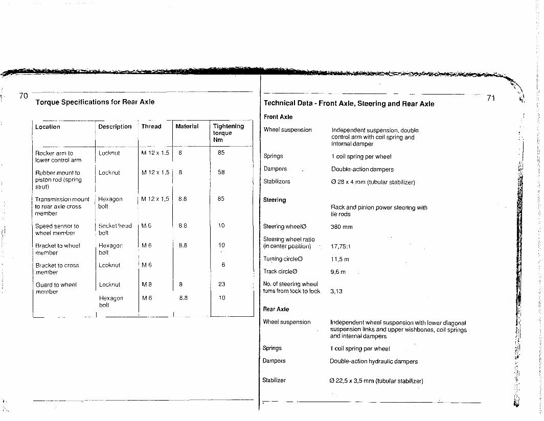
70 Torque Specifications for Rear Axle
Location
Rocker arm to lower control arm
Rubber mount to piston rod (spring strut)
Transmission mount to rear axle cross member
Speed sensor to wheel member
Bracke! to wheel member
Bracket to cross member
Guard to wheel member
Description Thread
Locknut
Locknut
qexagon 3olt
Socket head bolt
Hexagon bolt
Lcoknut
Locknut
Hexagon bolt
.-.- I
I
I
I
I
bl 12x 1.5
M 12x I,5
\/112x I,5
lv16
ME
M6
M8
M6
I --
l
Material
8
a
8.8
8.8
8.8
a
8.8
Tighteni torque Nm
85
58
85
10
IO
6
23
IO
Technical Data - Front Axle, Steering and Rear Axle
Front Axle
Wheel suspension Independent suspension, double control arm with coil spring and internal damper
Springs 1 coil spring per wheel
Dampers _ Double-action dampers
Stabilizers 0 28 x 4 mm (tubular stabilizer)
Steering Rack and pinion power steering with tie rods
Steering wheel0
Steering wheel ratio (in center position)
Turning circle0
Track circle0
No. of steering wheel turns from lock to lock
380 mm
17,75:1
il,5m
9,6m
3,13
Rear Axle
Wheel suspension Independent wheel suspension with lower diagonal suspension links and upper wishbones, coil springs and internal dampers
Springs 1 coil spring per wheel
3ampers Double-action hydraulic dampers
Stabilizer 0 22,5 x 3,5 mm (tubular stabilizer)
72 ~_~-~~---~~---. .-- -- ..- ~~~ ~.. ..--. ~.
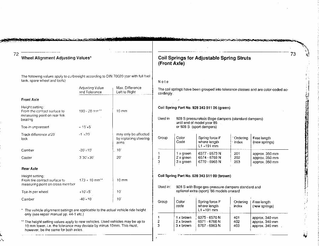
Wheel Alignment Adjusting Values*
The following values apply to curbweight according to DIN 70020 (car with full fuel tank. spare wheel and tools)
Adjusting Value Max. Difference and Tolerance Left to Right
Front Axle
Height setting: From the contact surface to measuring point on rear link bearing
190 - 20 mm”
Toe-in unpressed
Track difference at20 lock
+ 15’+5’
-I’+20
Camber
Caster
-30’+10’
3’30’+30’
Rear Axle
Height setting: From tire contact surface to 173+ IOmm” measuring point on cross member
Toe-in per wheel + 10’+5’
Camber -4O’+lO’
10 mm
may only be affected by replacing steering arms
IO’
20’
IOmm
IO’
IO’
l The vehicle alignment settings are applicable to the actual vehicle ride height only (see repair manual pp. 44-1 etc.)
l * The height setting values apply to new vehicles. Used vehicles may be up to 10 mm lower, i.e. the tolerance may deviate by minus 1 Omm. This must, however, be the same for both axles.
Coil Springs, for Adjustable Spring Struts (Front Axle)
Note
The coil springs have been grouped into tolerance classes and are color-coded ac- cordingly.
Coil Spring Part No. 928 343 511 06 (green)
Used in 928 S pressurele&s Boge dampers (standard dampers) until end of model year 85 or 928 S (sport dampers)
Group Color Code
Spring force F where length Ll =I91 mm
Ordering Free length index (new springs)
I. I x green 6377 - 6573 N 201 2 2 x green 6574 - 6769 N 202 3 3 x green 6770 - 6965 N 203
Coil Spring Part No. 928 343 511 09 (brown)
Used in:
Group
1 2 3
approx. 350 mm approx. 350 mm approx. 350 mm
928 S with Boge gas-pressure dampers standard and optional extra (sport) ‘86 models onward
Color code
1 x brown 2 x brown 3 x brown
i -
Spring force F where length Li =191 mm
6375 - 6570 N 6571 - 6766 N 6767 - 6963 N
i -
Ordering Free length index (new springs)
401 402 403
approx. 340 mm approx. 340 mm approx. 340 mm .
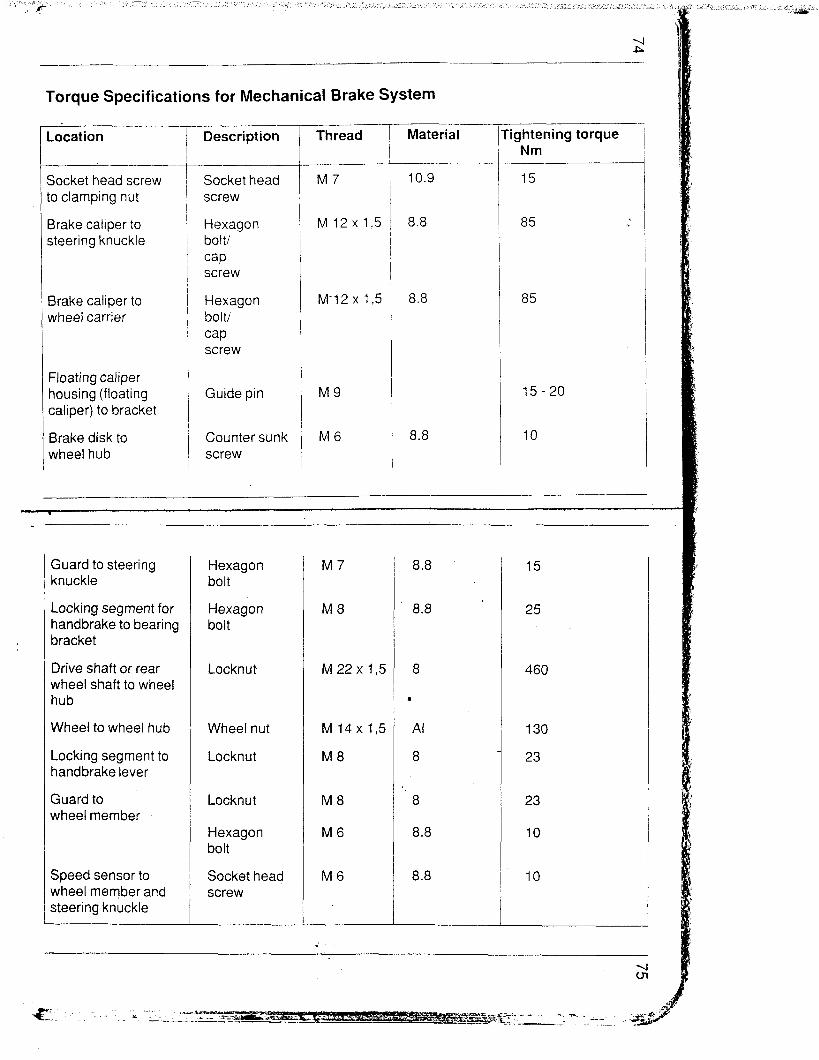
Torque Specifications for Mechanical Brake System
Location
Socket head screw to clamping nut
Brake caliper to steering knuckle
Brake caliper to wheel carrier
Floating caliper housing (floating caliper) to bracket
Brake disk to wheel hub
Description
Socket head screw
Hexagon bolt/ cap screw
Hexagon bolt/ cap screw
Guide pin
Counter sunk screw
-.-- Thread
M7
M 12x 1.5
M-12x 1.5
M9
M6
..-- Material
____. .~ 10.9
lightening torque Nm
85
85
Guard to steering knuckle
Locking segment for handbrake to bearing bracket
Drive shaft or rear wheel shaft to wheel hub
Wheel to wheel hub
Locking segment to handbrake lever
Guard to wheel member
Speed sensor to wheel member and steering knuckle
Hexagon bolt
Hexagon bolt
Locknut
Wheel nut
Locknut
Locknut
Hexagon bolt
Socket head screw
M7
M8
M22x1,5
M 14x15
M8
M8
M6
M6
8.8
’ 8.8
8
.
Al
8
” 8
8.8
8.8
460
130
23
23
10
10
.- ..-._
76 .~
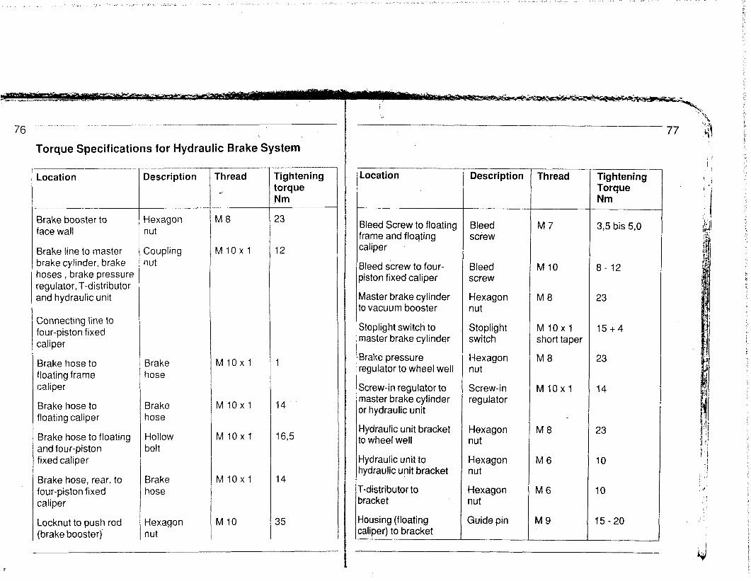
Torque Specifications for Hydraulic Brake System
Location
Brake booster to face wall
Brake line to master brake cylinder, brake hoses, brake pressure regulator, T-distributor and hydraulic unit
Connecting line to four-piston fixed caliper
Brake hose to floating frame caliper
Brake hose to floating caliper
Brake hose to floating and four-piston fixed caliper
Brake hose, rear, to four-piston fixed caliper
Locknut to push rod (brake booster)
Description
Hexagon nut
Coupling 1ut
Brake hose
Brake hose
Hollow bolt
Brake hose
Hexagon nut
Thread Tightening torque Nm
23
MlOxl 12
MlOxl 1
MlOxl 14.
MlOxl 16,5
MlOxl
Ml0
14
35
,
I I
I 1
I
I I
(
I t
I 1
I I
I
t (
Location Description Thread Tightening Torque Nm
Bleed Screw to floating Bleed M7 3,5 bis 5,0 frame and floating screw caliper
Bleed screw to four- Bleed M 10 8- 12 oiston fixed caliper screw
Master brake cylinder Hexagon M 8 23 to vacuum booster nut
Stoplight switch to Stoplight MlOxl 15+4 n-raster brake cylinder switch short taper
Brake pressure Hexagon M 8 23 regulator to wheel well nut
Screw-in regulator to Screw-in MlOxl 14 master brake cylinder regulator or hydraulic unit
Hydraulic unit bracket Hexagon M 8 23 to wheel well nut
i-iydraulic unit to Hexagon M 6 10 iydraulic unit bracket nut
T-distributor to Hexagon M 6 10 Iracket nut
-lousing (floating Guide pin M 9 15-20 :aliper) to bracket
1 i , .i
:. ,:i :d’
!

Technische Daten - Bremsanlage
sescription
3rake booster 0 iV
‘I
Brake master cylinder 0
. . front rear
Brake pressure regulator (screw-in regulator) Switching pressure Reduction factor
t
Mod. 85, Remarks1 Specifications
10 inches 3,8 (internal ratio)
23,81 mm 19,05 mm
33 bar 0,46
10 inches 4,5 (internal ratio)
87 models onward, pedal free travel is shorter
Tandem cylinder wit’ 2 central valves 23,81 mm 20.64 mm
18 bar 0,46
Brake disc 0 front rear
Eff. brake disc 0 front rear
Piston 0 in caliper front
rear 36 mm
, Pad surface per front wheel Pad surface per rear wheel Total pad surface
Pad thickness front rear
100 cm2
63 cm2 .
326 cm*
13 mm 13 mm
282 mm 289 mm
228 mm 242 mm
54 mm
304 mm 299 mm
250,8 mm 246 mm ’
86 models each fixed caliper 2x42+2x36mm
87* models onward each fixed caliper 2x44+2x36mm
each fixed caliper 2x30+2x28mm
126cm2
86 cm2
424 cm*
13 mm 13mm
2mm 2mm
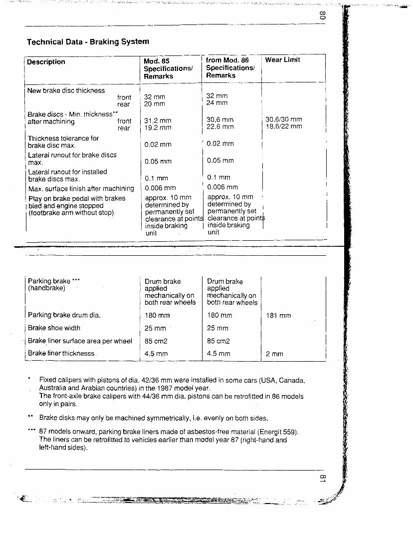
Technical Data - Braking System
r-
Description
New brake disc thickness front rear
Brake discs - Min. thickness** after machining front
rear
Thickness tolerance for brake disc max. Lateral runout for brake discs max. Lateral runout for installed brake discs max. Max. surface finish after machining Play on brake pedal with brakes bled and engine stopped (footbrake arm without stop)
Mod. 85 Specifications/ Remarks
32 mm 30 mm
31,2 mm 19.2 mm
0.02 mm
0.05 mm
0.1 mm 0.006 mm approx. 10 mm determined by permanently set clearance at point inside braking unit
S
from Mod. 86 Specifications/ Remarks ---
32 mm 24 mm
30,6 mm 22.6 mm
0.02 mm
0.05 mm
0.1 mm 0.006 mm approx. 10 mm determined by permanently set clearance at poin inside braking unit
Wear Limit
30.6/30 mm 18.6/22 mm
Parking brake *** (handbrake)
Parking brake drum dia.
Brake shoe width
Brake-liner surface area per wheel
Brake liner thicknesss.
Drum brake applied mechanically on both rear wheels
180 mm
25mm
85 cm2
4.5 mm
Drum brake applied mechanically on both rear wheels
180 mm 181 mm
25 mm
85 cm2
4.5 mm 2mm
* Fixed calipers with pistons of dia. 42/36 mm were installed in some cars (USA, Canada, Australia and Arabian countries) in the 1987 model year. The front-axle brake calipers with 44/36 mm dia. pistons can be retrofitted in 86 models only in pairs.
** Brake disks may only be machined symmetrically, i.e. evenly on both sides.
*** 87 models onward, parking brake liners made of asbestos-free material (Energit 559). The liners can be retrofitted to vehicles earlier than model year 87 (right-hand and left-hand sides).

Rims, Tires and Tire Pressure
Standard tires Tires Rims ET’”
85186 model 928 S front 225/50 VR16 7Jx16H2 65 rear 225150 VR16 7Jx16H2 65
87 mod. onward 92854 front 225/50 VR16 7Jx16H2 65 rear 245/45 VR16 8Jx16H2 52.3
928S4 front 225150 VR16 8Jx16H2 60 Club Sport rear 24945 VR16 9Jx16H2 60
(with 17 mm washer)
89 mod. onward 928 GT front 225/50 ZR16’ 8Jx16H2 60 rear 245i45 ZR 16’ 9Jx16H2 60
(with 17 mm washer)
t “ZR” 89 model onward “VR” above 210 km/h, “ZR” above 240 km/h
** rim offset in mm
Tire Pressure in bar (Summer Tires)
We
Front axle Rear Axle
928 S
2.5 bar 3.0 bar
928S4
2.5 bar 3.0 bar
928 S4 Club , Sport 928 GT
2.5 bar 3.0 bar
Collapsible spare tire until 85 models 2.2 bar, 86 models onward 2.5 bar Winter tires front 2.5 bar, rear 3.0 bar
Checking wheel Rims
Refer to drawing for radial and lateral runout measuring points on inner and outer rim shoulders.
Max. permissible radial and lateral runout for light alloy rims = 1 .O mm.
Note: Never straighten distorted wheel rims
-It-. --.--_

85
Location of Fuses and Relays
The central electric board is accessible after folding up a cover in foot- Nell of passenger’s side. It holds 45 fuses and 26 relais. The fuses are grouped into 5 blocks comprising 5 fuses each and are no longer num- bered. To check a special fuse it is necessary to count from left to right.
All wire harness plug connections for the central electric board are lo- cated below the relays and marked with letters A through W. The con- nectors have been.fitted with coding elements to avoid confusion.
Note:
The seat belt timer relay is located in the center console ahead of the radio, the rear window wiper relay behind the tool plate at rear left, the bulb controller in the passenger-side oddments tray.
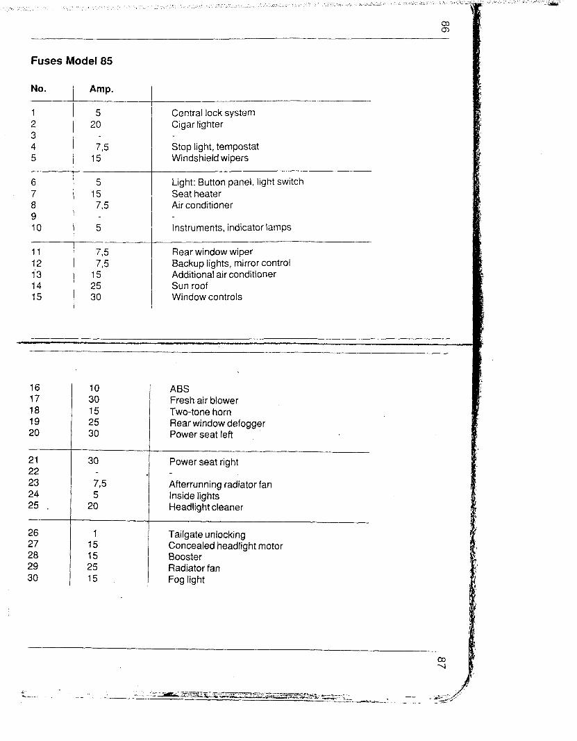
Fuses Model 85
No. ) Amp.
5 20
7,5 15
6 5 7 15 8 7,5 9 10 5
11 75 12 7,5 1’3 15 14 25 15 30
Central lock system Cigar lighter
Stop light, tempostat Windshield wipers
Light: Button panel, light switch Seat heater Air conditioner
Instruments, indicator lamps
Rear window wiper Backup lights, mirror control Additional air conditioner Sun roof Window controls
16 17 18 19 20
21 22 23 24 25 ,,
26 27 28 29 30
10 30 15 25 30
30
75 5
20
1 15 15 25 15
ABS Fresh air blower Two-tone horn Rear window defogger Power seat left
Power seat right
Afterrunning radiator fan Inside lights Headlight cleaner
Tailgate unlocking Concealed headlight motor Booster Radiator fan Fog light
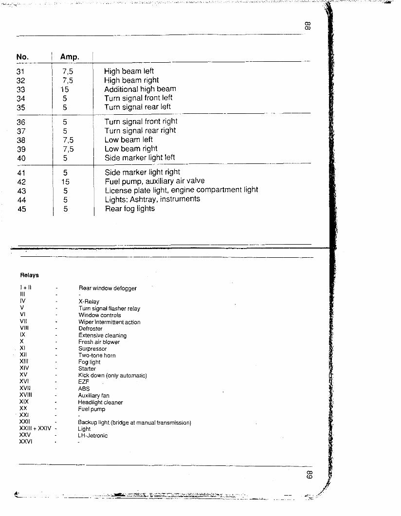
No.
31 32 33 34 35
36 37 38 39 40
41 42 43 44 45
Amp.
7,5 7,s
15 5 5
5 5 775 775 5
5 15 5 5 5
High beam left High beam right Additional high beam Turn signal front left Turn signal rear left
Turn signal front right Turn signal rear right Low beam left Low beam right Side marker light left
Side marker light right Fuel pump, auxiliary air valve License plate light, engine compartment light Lights: Ashtray, instruments Rear fog lights
Relays
1 + II III IV V VI VII VIII IX X XI XII XIII XIV xv XVI XVII XVIII XIX xx XXI XXII XXIII + XXIV - xxv - XXVI -
Rear window defogger
X-Relay Turn signal flasher relay Window controls Wiperintermittent action Defroster Extensive cleaning Fresh air blower Surpressor Two-tone horn Fog light Starter Kick down (only automatic) EZF ABS Auxiliary fan Headlight cleaner Fuel pump
Backup light (bridge at manual transmission) Light LH-Jetronic

Fuses Model 86
No. Amp.
5 25
7,5 15
6 7 a 9 10
5 15 7,5
5
11 12 13 14 15
7,5 7,5
15 25 30
! t r
Central lock system Cigar lighter
Stop light, tempostat Windshield wipers
Light: Button panel, light switch Seat heater Air conditioner
Instruments, indicator lamps
Rear window wiper Backup lights, mirror control Additional air conditioner Sun roof Window controls
16 15 17 30 la 15 19 25 20 30
ABS Fresh air blower Two-tone horn Rear window defogger Power seat left
21 22 23 24 25
30 Power seat right
795 Afterrunning radiator fan 5 Inside lights
25 Headlight cleaner
26 1 Tailgate unlocking 27 15 Concealed headlight motor 28 15 Booster 29 25 Radiator fan 30 15 Fog light

No.
31 32 33 34 35
36 37 38 39 40
41 42 43 44 45
Amp. __
7,5 775 15 5 5
5 5 7,5 775 5
5 15 5 5 5
High beam left High beam right Additional high beam Turn signal front left Turn signal rear left
--
Turn signal front right Turn signal rear right Low beam left Low beam right Side marker light left
Side marker light right Fuel pump, auxiliary air valve License plate light, engine compartment light Lights: Ashtray, instruments Rear fog lights
Relays
I + II III IV V VI VII VIII IX X XI XII XIII XIV xv XVI XVII XVIII XIX xx XXI XXII XXIII + XXIV xxv xxvi
Rear window defogger
X-Relay Turn signal flasher relay Window controls Wiper intermittent action Defroster Extensive cleaning Fresh air blower Surpressor Two-tone horn Fog light Starter Kick down (only automatic) EZF ABS Auxiliary fan Headlight cleaner Fuel pump Inside light Backup light (bridge at manual transmission) Light LH-Jetronic

Fuses Model 87188
8 15 9 10 5
Air conditioner Light: Button panel, light switch, diagnosis connection Seat heater
Instruments, indicator lamps, solenoid valve Kick down
11 775 Rear window wiper 12 7,5 Backup lights, mirror control 13 15 Additional air conditioner 14 25 Sun roof 15 30 Window controls
Central lock system Cigar lighter Control unit fan Stop light, tempostat Windshield wipers, heated spray jet
,“,_~. ., ’
16 15 17 30 18 15 19 25 20 30
21 30 22 15 23 7,5 24 7,5' 25 25
26 1 27 15 28 30 29 30 30 15
ABS Fresh air blower Two-tone horn Rear window defogger Power seat left
Power seat right Booster Fresh air flap motor’ Inside lights, diagnosis connection. Headlight cleaner
Tailgate unlocking Concealed headlight motor Radiator fan 1 Radiator fan 2 Fog light

No. I
31 32 33 34 35
36 37 38 39 40
41 42 43 44 45
Amp. ~
775 775
15 5 5
5 _ 5 775 775 5
5 15
5 5 5
High beam left High beam right Additional high beam Turn signal front left Turn signal rear left
Turn signal front right Turn signal rear right Low beam left Low beam right Side marker light left
Side marker light right Fuel pump, heater, Oxygen sensor License plate light, engine compartment light Lights: Ashtray, instruments Rear fog lights
Relay
I + II III IV V VI VII _ VII IX X XI XII XIII XIV xv XVI XVII XVIII XIX xx XXI XXII XXIII + XXIV xxv XXVI
Rear window defogger
X-Relay Turn signal flasher relay Window controls Wiper intermittent action Defroster Extensive cleaning Fresh air blower Surpressor Two-tone horn Fog light Starter Kick down (only automatic) EZK ABS Flap control Headlight cleaner Fuel pump Inside light Backup light (bridge at manual transmission) Light LH-Jetronic

Fuses Model 89
No. Amp.
15 25
5 7,5
25
6 7
i I 7,5
5
8 15 9 7,5 10 5
11 12
13 14 15
I 7,5 7,5
15 25 30
. -
Central lock system Cigar lighter Control unit fan Stop light, tempostat Windshield wipers, heated spray jet
.- Air conditioner Light: Button panel, light switch, diagnosis connection Seat heater Telephone Instruments, indicator lamps, solenoid valve Kick down
Rear window wiper Backup lights, mirror control, tire pressure control Additional air conditioner Sun roof Window controls
16 15 ABS 17 30 Fresh air blower 18 15 Two-tone horn 19 25 Rear window defogger 20 30 Power seat left
21 30 Power seat right 22 15 Booster 23 7,5 Fresh air flap motor 24 7,5 Inside lights, diagnosis connection, combi 25 25 Headlight cleaner
26 1 Tailgate unlocking 27 15 Concealed headlight motor 28 30 Radiator fan 1 29 30 Radiator fan 2 30 15 Fog light
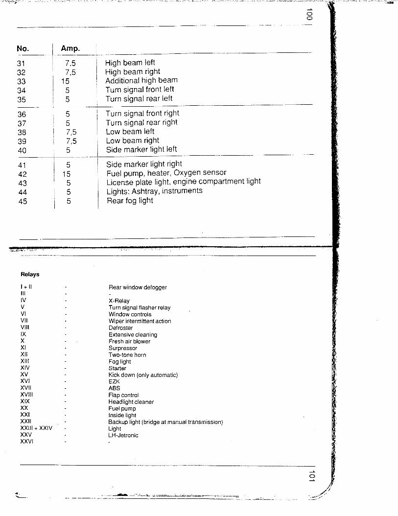
No. -.-
31 32 33 34 35
36 37 38 39 40
41 42 43 44 45
I
I-
t t
I
!
!
t
Amp.
775 775
15 5 5
5 5 775 7,5 5
5 15
5 5 5
._
High beam left High beam right Additional high beam Turn signal front left Turn signal rear left
Turn signal front right Turn signal rear right Low beam left Low beam right Side marker light left
Side marker light right Fuel pump, heater, Oxygen sensor License plate light, engine compartment light Lights: Ashtray, instruments Rear fog light
Relays
I + II III IV V VI VII VIII IX X XI XII XIII xiv xv XVI XVII XVIII XIX xx XXI XXII XXIII + XXIV xxv XXVI
Rear window defogger
X-Relay Turn signal flasher relay . Window controls Wiper intermittent action Defroster Extensive cleaning Fresh air blower Surpressor Two-tone horn Fog light Starter Kick down (only automatic) EZK ABS Flap control Headlight cleaner Fuel pump Inside light Backup light (bridge at manual transmission) Light LH-Jetronic

88 h-v ~0~4 se 6 OS 1 c 88 hT ‘JJOJj se 6 OS6
yw-ip iossejdwo=> A z t le I\r\ ~9 .xoldde $0 I.ndu! JaMOd
.leq s ? 09 40 aJnSSaJd we1 P!W le suado al\ler\ hajeS uo BAJEA &3ps
JOSSaJdUJO3
9 iwJaa pJ3 OZ 7 082 u! I!O 6uyzJa6!J~atj
z t tj WJa@JlaJ i0 6 OOZ 1 JCXIO!~!pUO:, J!E? ‘PPe qI!M
z t tt WeJa6!JjaJ 40 6 OS0 t awnloA lUeJa6!Jptj
.lauo!Jpuo~ J!Jj JO e1eC) le3juyDal
Torque Specifications -Air Conditioner
Location
Compressor-Suction line
Compressor-Pressure line
Condenser-inlet
Condenser-Fluid tank
Fluid tank- evaporator
Expansion valve- Pressure line
Expansion valve- Suction line
Expansion valve- evaporator
Description
Coupling nut
Coupling nut
Coupling nut
Coupling nut
Coupling nut
Coupling bolt
Coupling bolt
Coupling bolt
Thread
7/8”,~ 14 UNF
3/4” x 16 UNF
3/4” x 16 UNF
314” x 16 UNF
98” x 18 UNF
518” x 18 UNF
7/8” x 18 NS
3/4” x 18 NS
Tightening torque
33 Nm
24Nm .
24 Nm
24 Nm
17Nm
17Nm
33 Nm
24 Nm
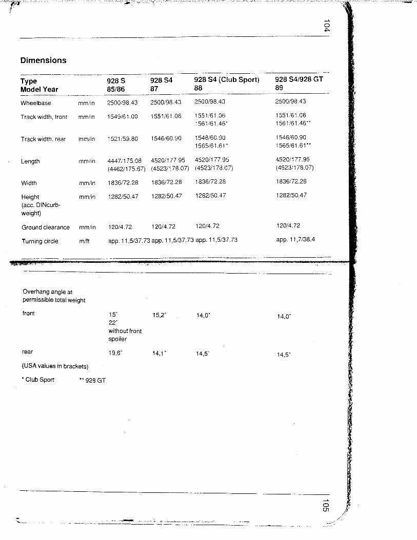
Dimensions _~-
Type 928 S 928 S4 928 S4 (Club Sport) 928 S4/928 GT Model Year 85186 87 88 89
Wheelbase mm/in 25ool98.43 2500198.43 2500198.43 2500198.43
Track width, front mm/in 1549161.00 1551161.06 1551161.06 1551!'61.06
1561i61.46' 1561161.46"
Track width, rear mm/in 152i159.80 1546i60.90 1548160.90 1546160.90
1565161.61' 1565161.61"
Length mm/in 44471175.08 45201177.95 45201177.95 45201177.95
(44621175.67) (45231178.07) (45231178.07) (4523/178.07)
Width mm/in I 836172.28 I 836172.28 I 836172.28 I 836172.28
Height mm/in I 282150.47 i 282150.47 i 282150.47 i 282150.47
(act. DINcurb- weight)
Ground clearance mm/in 12014.72 120/4.72 12014.72 12014.72
Turning circle mift app. 11,5/37.73 app. 11,5/37.73 app. 11,5/37.73 app. 11,7i38.4
Overhang angle at permissible total weight
front 15" 15,2" 14,O' 22'
without front spoiler
rear 19,6” 14,l” 14,5'
(USA values in brackets)
* Club Sport ** 928 GT
14,O'
14,5'
..*
‘L- - --- . ..i. i .---A_._ ._,. __-- __.i -..-
-..-. .---A.--_ .

Performance Data (act. Din curbweight and half vehicle capacity weight)
Type Model Year
Max. speed
- 928 S 928 S 928 54
85 86 87188
Manual Automatic Manual Automatic Manual Automatic
transm. transm. transm. transm. transm. transm. --__
kmih 255 (250) 250 (242) 255 (250) 250 (242) 270 (265) 265 (260)
mph 155 (155) 150 (152) I 58 (155) 155 (150) 168 (165) 165 (162)
Acceleration
O...lOO km/h
6,2 6.7 6.2 637
(613)
5,9
(W
63
(6.0) (6.6)
Kilometer from
standing start
S 25,6
(25,a)
26.3
(263)
25,6
(25,a)
26,3
(26.8)
25,4 25,9
(254) (262)
l/4 mile from S (142) (149) (14.2) (14,9) 14,2 14,5
Type Model Year
928 S4
89
Manual
928 GT 928 S4
89
Automatic
standing start
transm. transm.
Max. speed km/h 270 275 265
mph 168 171 165
Acceleration
O...lOO km/h S -59 53 673
Kilometer from
standing start S 25,4 25,2 25,9
l/4 mile from
standing start S 14,2 14,l 14,5
(USA values in brackets)

Weights ^__ Type Model Year
- Curbweight to DIN*
.--__ 928 928 S4 928 S4/928 GT 85186 87 88189
___- Europe. USA Europe, USA Europe, USA R.O.W. R.O.W. R.o.W.
- _- ._____
kg 1530 kgllbs 152013351 kg 1580 kg:lbs 159Oi3505 kg 1580 kgllbs 159013505
Penn. total weight kg 1890 kgllbs 187014123 kg 1920 kgilbs 192014233 kg 1920 kgilbs 190014189
Perm. axial laod front** kg 920 kg/lbs 90011984 kg 920 kg/lbs 92012028 kg 920 kgilbs 92012028
Perm. axial load rear** kg 1100 kgllbs 100012205 kg 1100 kglfbs 110012425 kg 1100 kgilbs 110012425
Perm. trailer load kg 750 kg 750 kg 750
unbraked*‘*
Perm. trailer load kg 1600 kg 1600 kg 1600 brakedt””
Perm. roof load” kg 35 kgllbs 35177 kg 35 kgllbs 35177 kg 35 kgllbs 35177 with Porsche roof kg 75 kgllbs 751165 kg 75 kg/lbs 751165 kg 75 kgllbs 75il65
transport system from Mod. 82
Perm. drawbar kg 75 kg 75 kg 75
Perm. towing weight kg 3490 kg 3520 kg 3520
t With extra equipment up to 1550 kg or 1560 for USA models (the vehicle capacity weight is reduced
** correspondingly). From Model 87 up to 1600 kg or 1610 kg. The permissible total weight must not be exceeded.
*** Up to 16 % incline

Filling Capacities
Engine oil specification
Engine oil volume
Cooling system incl. heater
Power steering
permissible: API SE/SF mit Kombination API SE/CC - SE/CD -
SF/CC - SF/CD Multi-grade oil as approved by plant Technical Information Engine Oils
Approx. 7.5 Itr., plus 0.5 Itr. when replacing filter (exact amount depending on marks on oil dipstick). Amount of oil between “Min.“- und “Max.“- marks on oil dipstick = approx. 1.5 I.
Approx. 16 Itr. of coolant, plant filling ,with anti-freeze for temperatures to -3OOC (-40°C for arctic countries). Only use anti-freeze and corrosion inhibiting products, which are suitable for light alloy engines and radiators.
Approx. 0,7 Itr. ATF (only Dexron II D)
Fuel tank
Brake fluid reservoir
Windshield washer with headlamp washer system
Intensive cleaning system
Manual transmission with differential
Automatic transmission with converter
Rear axle drive
Approx. 86 Itr., 8 Itr. of which as reserve
Approx. 0.2 Itr. brake fluid in accordance with SAE J 1703 or DOT 3
Approx. 9.0 Itr. water, from model 86 approx. 7.5 Itr. water
Approx. 0.6 Itr. “Porsche Special Silicone Remover”
Multi-grade transmission oil SAE 75 W 90 API-classification GL 5 (or MIL-L 2105 B). Filling capacity until model1 85 approx. 3,8 I (from model 86 approx. 4,5 I)
Filling capacity approx. 8,0 I (from model 87 approx. 9,3 I) Oil change capacity with converter approx. 6.0 Itr. (from model 87 approx. 7.3 Itr.) ATF-Dexron II D
Filling capacity ca. 2,7 I (from model 87 approx. 3,0 I) API-classification GL 5 (MIL-L 2105 B) SAE 90