Embed Size (px)
Citation preview

Unit No.03Front axle, Steering system, Rear axle,
Wheel & Tyres
Prepared by,
Prof. Santosh Kailas Chandole
ME (Design Engineering)
BE (Automobile Engineering)
Steering system
STEERING REQUIREMNTS:
• It should be accurate and easy to handle.
• The effort to steer should be minimal and must not be tiresome to the driver.
• The steering mechanism should provide directional stability. This implies that the vehicle should have the tendency to return to its straight ahead position.
• It should minimize wear of tyres.
•TYPES OF STEERING GEAR:
1. Worm and nut steering gear.2. Cam and double rolling steering gear.3. Worm and nut steering gear.4. Recirculating ball type steering gear.5. Rack and pinion steering gear.

Ackerman Steering Mechanism• At any angle of steering, the centre point of all the circular path traced
by all the wheels will coincide at a common point.
• It is difficult to achieve with simple linkages. However, it is
applicable for low speed.

Steering Geometry
a) Camber:- The tilt of the car from vertical is called Camber. It is positive if it tilt outward at the top. It s also called wheel rake. The right drive vehicle which must be driven on left side if the road must be given higher camber on right side and vice versa.
The tyre life will be maximum if the camber angle at running condition is zero. Positive camber also causes the wheel to toe-out. i.e. camber should not be more than 2º .

Steering Geometry
b) Castor :- The angle between the king pin and the vertical in the pane of the wheel is called Castor angle. When the king pin centre line meets the ground at a point ahead of the vertical wheel centre line, it is called Positive castor, on the other hand if it is behind the wheel centre line it is called Negative castor.

Steering Geometry
c) TOE IN AND TOE OUT: The front wheels are slightly turned in at front side such that the distance between wheels at front (A) is little less than the distance at back (B), when seen from top. This difference in distance is called toe-in. It is shown in Figure 7.7. The distance B is greater than A by 3 to 5 mm.

d) King pin inclination:It is the angle between king pin centre line and vertical line when seen from the front of the vehicle. t is also called steering axle inclination.
• King pin inclination and caster are used to improve directional stability in cars.
• This is also used to reduce steering effort when steering a stationary it reduces tyre wear.
• This inclination varies from 4 to 8 degree in modern cars.

Understeer and oversteer: are vehicle dynamics terms used to describe the sensitivity of a vehicle to steering. Simply put, oversteer is what occurs when a
car turns (steers) by more than the amount commanded by the driver.

Power steering system employs Electronic Power Steering (EPS) system that is Column assist type. EPS consist of EPS control module and steering column assembly (i.e. P/S motor and torque sensor).
The controllability of assisting steering force is optimised by the All Range Controllable P/S control module in all speed ranges.
Power Steering

Description of EPS system components:
Contin……Power Steering
EPS system components Functions.
A). Steering column Assembly;
Torque sensor.
P/S Motor.
1). Both the main and sub torque sensor regulate the voltages.
2). According to applied steering force and direction and sent the output voltages toP/S control module.
3). P/S motor assist steering force by motor torque that is generated according toelectric current value from P/S control module.
B). P/S control module. 1). P/S control module determines the ratio of steering force based on voltage from torque sensors and vehicle speed signal from ECM and control electric signal for P/S motor.
2). P/S control module judges engine condition from engine speed signal for P/S motor.
C). ECM. 1). ECM output engine speed signal to P/S control module.
2). ECM output vehicle speed signal to P/S control module.
D). EPS Warning light. 1). EPS warning light illuminates when one of the system’s components malfunction.

Collapsible SteeringTo transfer energy from the steering wheel into the
steering gear box.
The column will collapse in an accident, thus helping to avoid striking the driver . A typical collapsible steering column looks like two interlocking shafts that attach directly to the steering wheel and the steering gear box.
Working: Collapsible steering columns still consist of a long shaft that connects the steering wheel to the steering gear box. The collapsible design is composed of an inner and an outer sleeve, pressed tightly together with a number of steel bearings in between. The steel bearings between the sleeves break free, allowing the inner sleeve to be moved further into the outer sleeve . Thus absorb the energy and drivers remain completely unaware of the danger they have avoided.Advantages:Front-end Collision An energy-absorbing steering columncollapses, reducing trauma to a driver's head, neck andbreastbone. Rear Impact: Installation of an energy-absorbing steering column decreases rearward displacement.

Front wheels of the vehicle are mounted on front axles .
1. It supports the weight of front part of the vehicle.
2. It facilitates steering.
3. It absorbs shocks which are transmitted due to road surface irregularities.
4. It absorbs torque applied on it due to braking of vehicle.
There is two types of front axles :
(a)Dead front axle, and
(b)Line front axle.
Dead Front Axle: Dead axles are those axles, which donet rotate. These axles have
sufficient rigidity and strength to take the weight. The ends of front axle are suitably designed
to accommodate stub axles.
Line Front Axle: Line axles are used to transmit power from gear box to front wheels.
Line front axles although, front wheels.

Dead & Live axle

Stub axles are connected to the front axle by king pins. Front
wheels are mounted on stub axles arrangement for steering.
Stub axle turns on king pins. King pins is fitted in the front
axle beam eye and is located and locked there by a taper cotter
pin. Stub axles are of four types:
Elliot Reversed Elliot Lamoine
Reversed Lamoine

TYPES OF STUB AXLES

Wheels and Tyres
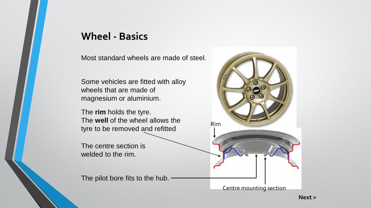
Wheel - Basics
Some vehicles are fitted with alloy
wheels that are made of
magnesium or aluminium.
The pilot bore fits to the hub.
Most standard wheels are made of steel.
The rim holds the tyre.
The well of the wheel allows the
tyre to be removed and refitted
The centre section is
welded to the rim.
Centre mounting section
Rim
Next >

Wheel Sizes

Tyres
Basis Functions
• The tyre acts as the primary suspension, cushioning the vehicle from the effects of a rough surface.
• It also provides frictional contact with the road surface.
• This allows the driving wheels to move the vehicle.
• The front tyres allows the wheels to steer .
• The tyres allow the brakes to slow or stop the vehicle

Pneumatic Tyres
• The tyre is a flexible casing, which contains air.
• Tyres are manufactured from reinforced synthetic rubber.
• The tyre is made from an inner layer of fabric plies, which are wrapped around bead wires at the inner edges.
• The bead wires hold the tyre in position on the wheel rim.
• The fabric plies are coated with rubber, which is moulded to form the side walls and tread of the tyre. Behind the tread is a reinforcing band, usually made of steel,rayon,or glass fibre. Modern tyres are mostly tubeless, so they have a thin layer of rubber coating inside to act as a seal.

Tyre Construction
• Cross – ply tyres are not used on any mass produced modern cars. However, the construction details are useful to show how tyre technology has developed.
• Several textile plies are laid across each other, running from bead to bead in alternate directions.
• The number of plies depends on the size of the tyre and the load it has to carry.
• The same number of plies is used on the crown and the sidewalls.

Tyre Construction
• Radial – Ply tyres consist of a carcass ply formed by textile arcs running from one bead to the other.
• Each ply which is laid in an arc at an angle of 90 degrees to the direction the tyre rolls.
• At the top of the tyre crown (under the tread), there is a belt made up of several plies reinforced with metal wire, laid on top of the carcass ply.
• These crown plies, laid one on top of the other, overlap at an angle determined by the type of the tyre.

Tyre Specifications
P 205/55 V R 16
TYPEP - PASSENGERT - TEMPORARY
LT - LIGHT TRUCKC - COMMERCIAL
WIDTH(MILLIMETERS)
145-315
ASPECT RATIO(HEIGHT/WIDTH %)
55, 60, 65 70 ETC
TYPEB - BIAS-BELTED
D - DIAGONAL BIAS R -RADIAL
RIM DIAMETER(INCHES) 13, 14 ETC
P 205/55 V R 16P 205/55 V R 16P 205/55 V R 16P 205/55 V R 16P 205/55 V R 16P 205/55 V R 16P 205/55 V R 16
SPEED RATINGB (31 MPH) -
V (150 MPH) -Z (OVER 150 MPH)
Next >

• Remember the tyre tread depth must be not less than 1.6mm over the central three-quarters of the tyre and must go all the way round the circumference in an continuous unbroken band with no bald patches anywhere on the tyre tread.
• If radial and crossply tyres are fitted to the same vehicle, the radial-ply tyres must only be fitted to the rear.
• Cross-ply and radial ply tyres must never be fitted to the same axle.
• Tyre pressures must be set to the manufactures recommendations
• The tread and side wall must be free from large cuts, abrasions or bubbles


![arXiv:1803.03758v2 [cs.RO] 13 Apr 2020Fig.3: Ackerman Steering Geometry (left) and Side-slip Angles (left) In Fig. (3), the Ackerman steering geometry is depicted on the right. The](https://img.dokumen.tips/doc/110x75/60727960a46e7d213b15233d/arxiv180303758v2-csro-13-apr-2020-fig3-ackerman-steering-geometry-left.jpg)