Embed Size (px)
Citation preview
Ch. 5: Distributed Forces
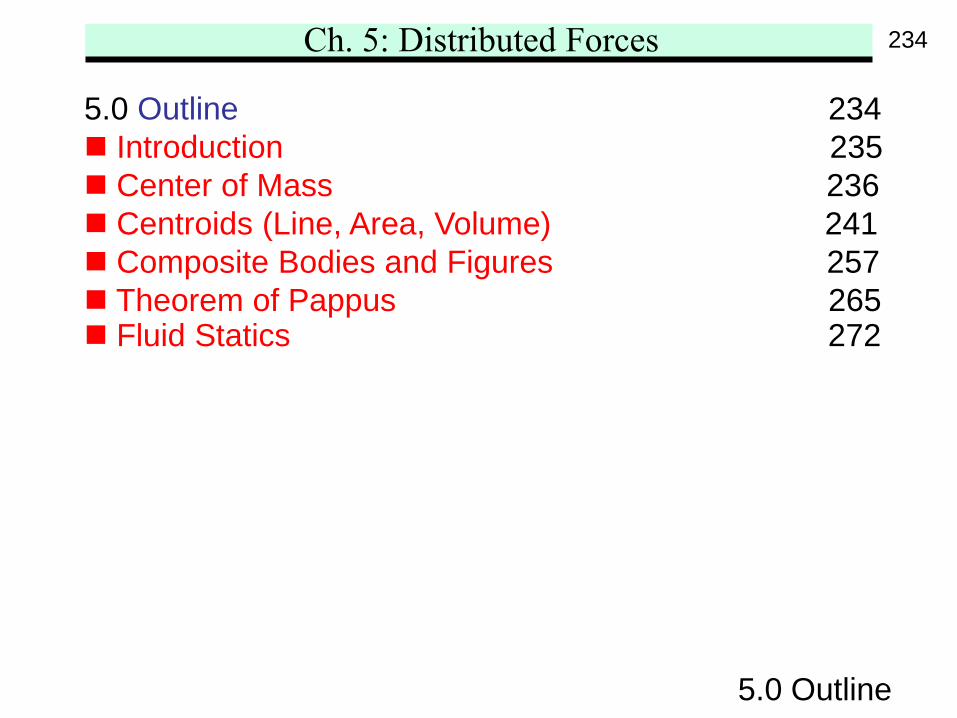
5.0 Outline 234 Introduction 235 Center of Mass 236 Centroids (Line, Area, Volume) 241 Composite Bodies and Figures 257 Theorem of Pappus 265 Fluid Statics 272
5.0 Outline
234
Ch. 5: Distributed Forces
5.0 Introduction
5.0 Introduction
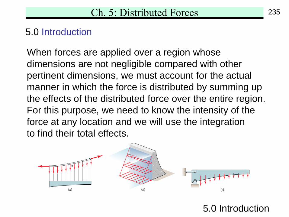
When forces are applied over a region whosedimensions are not negligible compared with otherpertinent dimensions, we must account for the actualmanner in which the force is distributed by summing upthe effects of the distributed force over the entire region.For this purpose, we need to know the intensity of theforce at any location and we will use the integrationto find their total effects.
235
Ch. 5: Distributed Forces
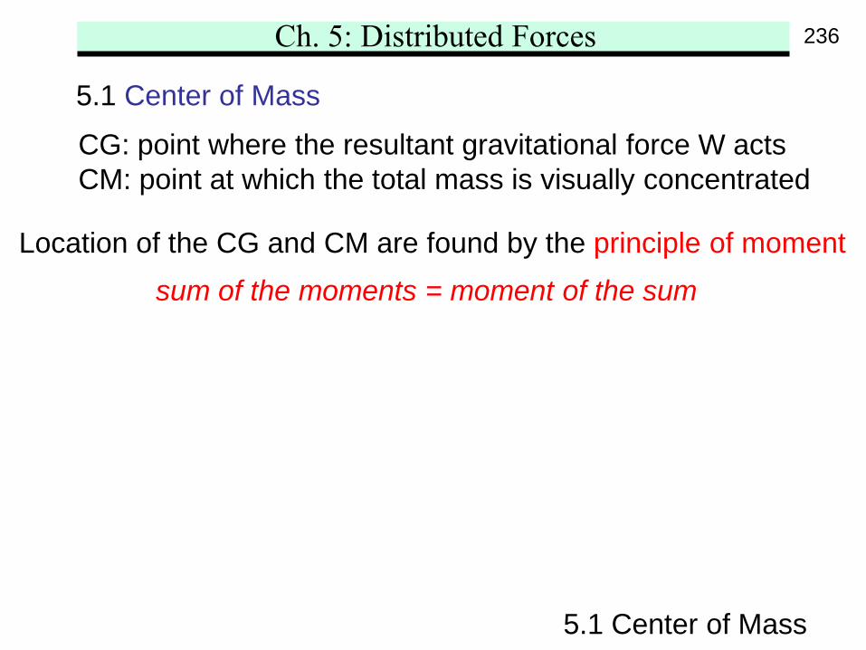
5.1 Center of Mass
5.1 Center of Mass
Location of the CG and CM are found by the principle of moment
CG: point where the resultant gravitational force W actsCM: point at which the total mass is visually concentrated
sum of the moments = moment of the sum
236
Ch. 5: Distributed Forces
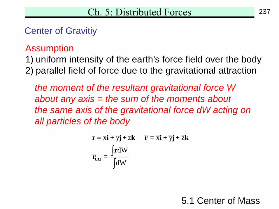
Center of Gravitiy
5.1 Center of Mass
Assumption1) uniform intensity of the earth’s force field over the body2) parallel field of force due to the gravitational attraction
the moment of the resultant gravitational force Wabout any axis = the sum of the moments aboutthe same axis of the gravitational force dW acting onall particles of the body
x y z x y z
dW
dW
=
∫∫
CG
r i + j+ k r = i + j+ k
rr =
237
Ch. 5: Distributed Forces
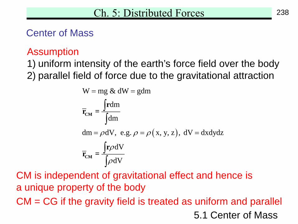
Center of Mass
5.1 Center of Mass
( )
W mg & dW gdm
dm
dm
dm dV, e.g. x, y, z , dV dxdydz
dV
dV
ρ ρ ρ
ρ
ρ
= =
= = =
∫∫
∫∫
CM
CM
rr =
rr =
Assumption1) uniform intensity of the earth’s force field over the body2) parallel field of force due to the gravitational attraction
CM = CG if the gravity field is treated as uniform and parallel
CM is independent of gravitational effect and hence isa unique property of the body
238
Ch. 5: Distributed Forces
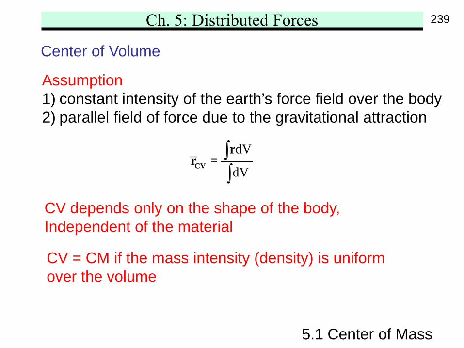
Center of Volume
5.1 Center of Mass
Assumption1) constant intensity of the earth’s force field over the body2) parallel field of force due to the gravitational attraction
CV depends only on the shape of the body,Independent of the material
dV
dV∫∫
CV
rr =
CV = CM if the mass intensity (density) is uniformover the volume
239
Ch. 5: Distributed Forces
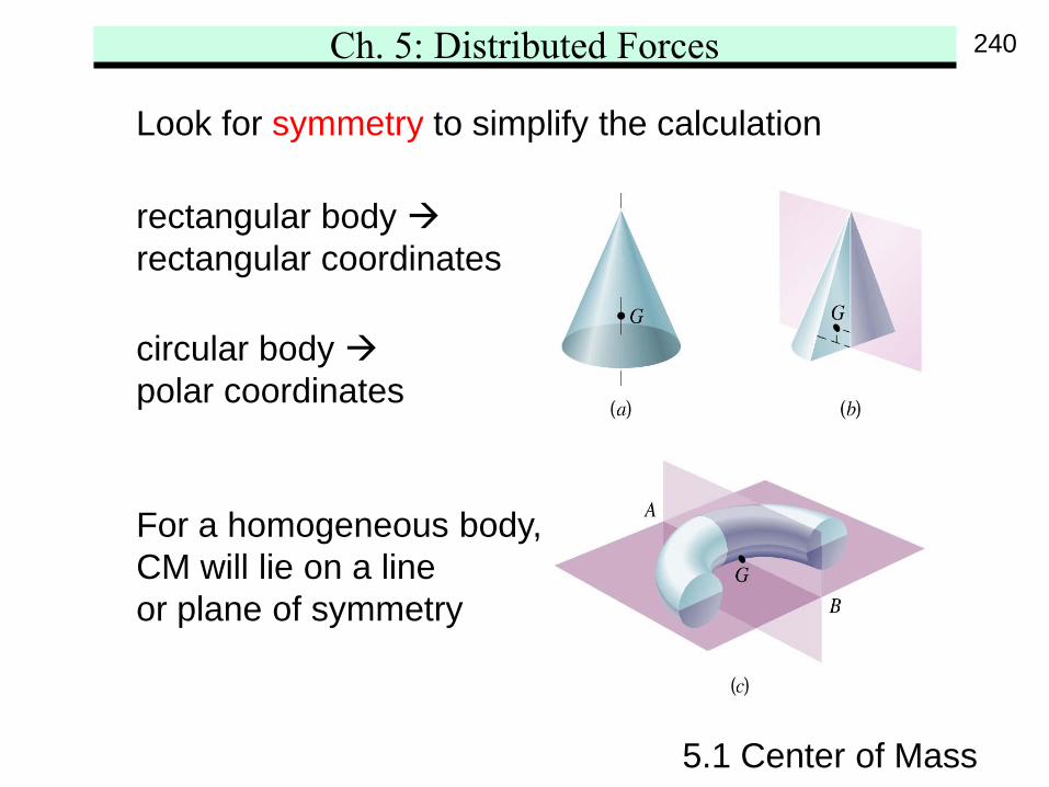
5.1 Center of Mass
Look for symmetry to simplify the calculation
rectangular body rectangular coordinates
circular body polar coordinates
For a homogeneous body,CM will lie on a lineor plane of symmetry
240
Ch. 5: Distributed Forces
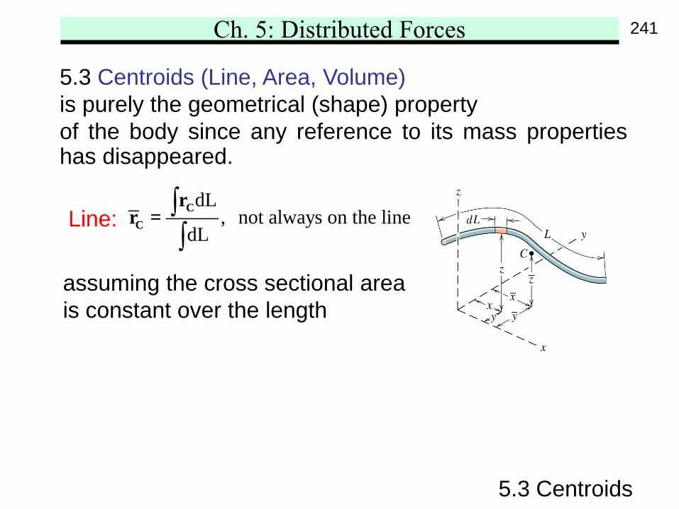
5.3 Centroids (Line, Area, Volume)is purely the geometrical (shape) propertyof the body since any reference to its mass properties has disappeared.
5.3 Centroids
Line:dL
, not always on the linedL
∫∫
CC
rr =
assuming the cross sectional areais constant over the length
241
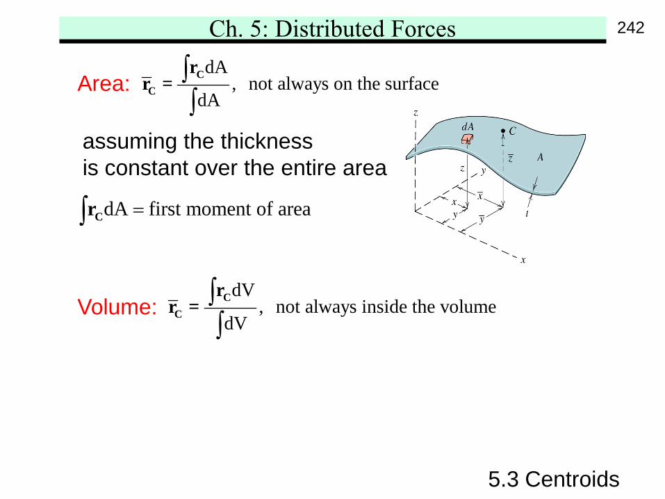
Ch. 5: Distributed ForcesdA
, not always on the surfacedA
∫∫
CC
rr =
5.3 Centroids
Area:
assuming the thicknessis constant over the entire area
dV, not always inside the volume
dV∫∫
CC
rr =
dA first moment of area=∫ Cr
Volume:
242
Ch. 5: Distributed Forces
5.3 Centroids
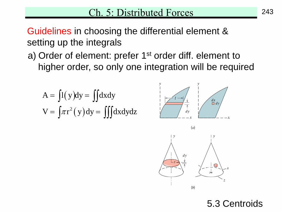
Guidelines in choosing the differential element &setting up the integralsa) Order of element: prefer 1st order diff. element to
higher order, so only one integration will be required
( )( )2
A l y dy dxdy
V r y dy dxdydzπ
= =
= =
∫ ∫∫∫ ∫∫∫
243
Ch. 5: Distributed Forces
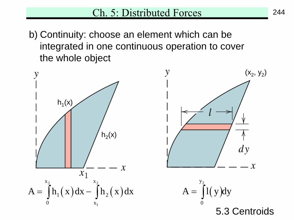
5.3 Centroids
b) Continuity: choose an element which can beintegrated in one continuous operation to coverthe whole object
( ) ( )2 2
1
x x
1 20 x
A h x dx h x dx= −∫ ∫ ( )2y
0
A l y dy= ∫
h1(x)
h2(x)
(x2, y2)
244
Ch. 5: Distributed Forces
dxdy∫
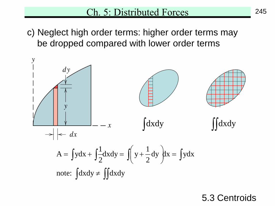
5.3 Centroids
c) Neglect high order terms: higher order terms maybe dropped compared with lower order terms
1 1A ydx dxdy y dy dx ydx2 2
note: dxdy dxdy
= + = + =
≠
∫ ∫ ∫ ∫
∫ ∫∫
dxdy∫∫
245
Ch. 5: Distributed Forces
( )O Ox , y
5.3 Centroids
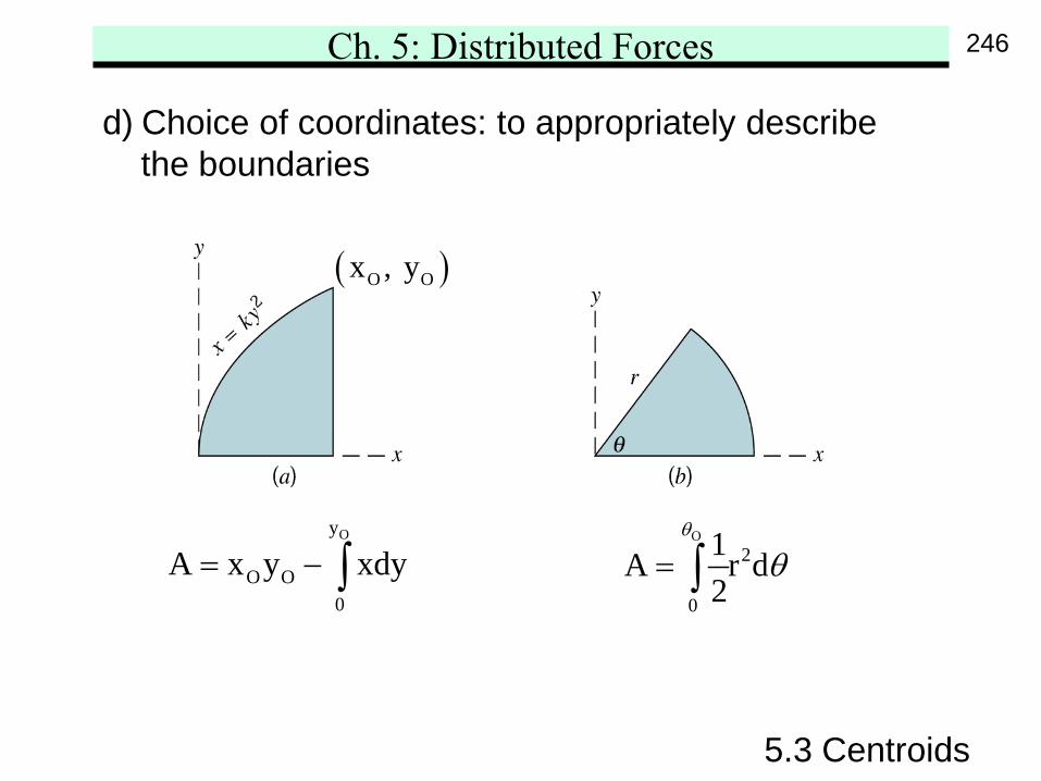
d) Choice of coordinates: to appropriately describethe boundaries
Oy
O O0
A x y xdy= − ∫O
2
0
1A r d2
θ
θ= ∫
246
Ch. 5: Distributed Forces
5.3 Centroids
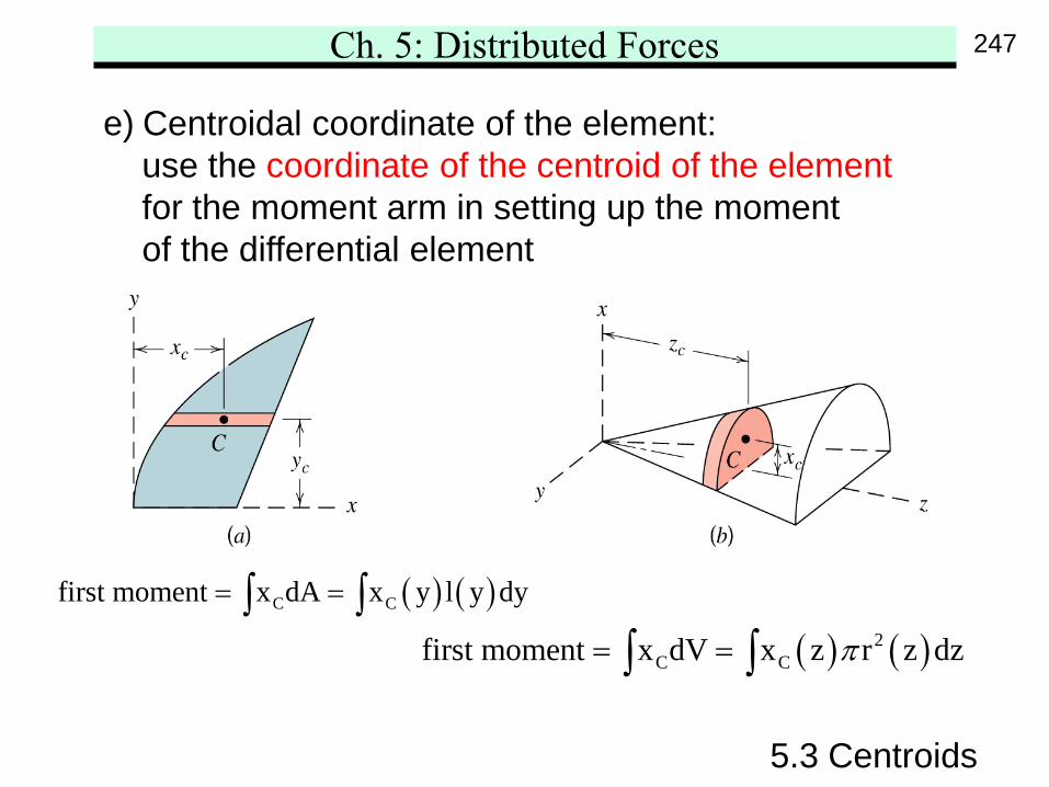
e) Centroidal coordinate of the element:use the coordinate of the centroid of the elementfor the moment arm in setting up the momentof the differential element
( ) ( )C Cfirst moment x dA x y l y dy= =∫ ∫( ) ( )2
C Cfirst moment x dV x z r z dzπ= =∫ ∫
247
Ch. 5: Distributed Forces
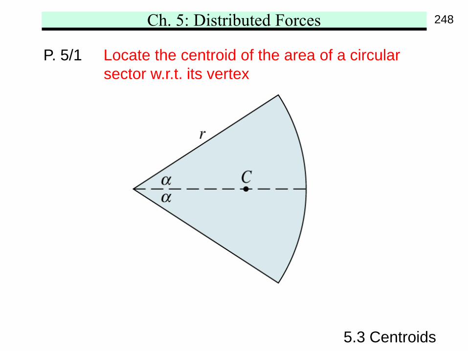
5.3 Centroids
P. 5/1 Locate the centroid of the area of a circularsector w.r.t. its vertex
248
Ch. 5: Distributed Forces
5.3 Centroids
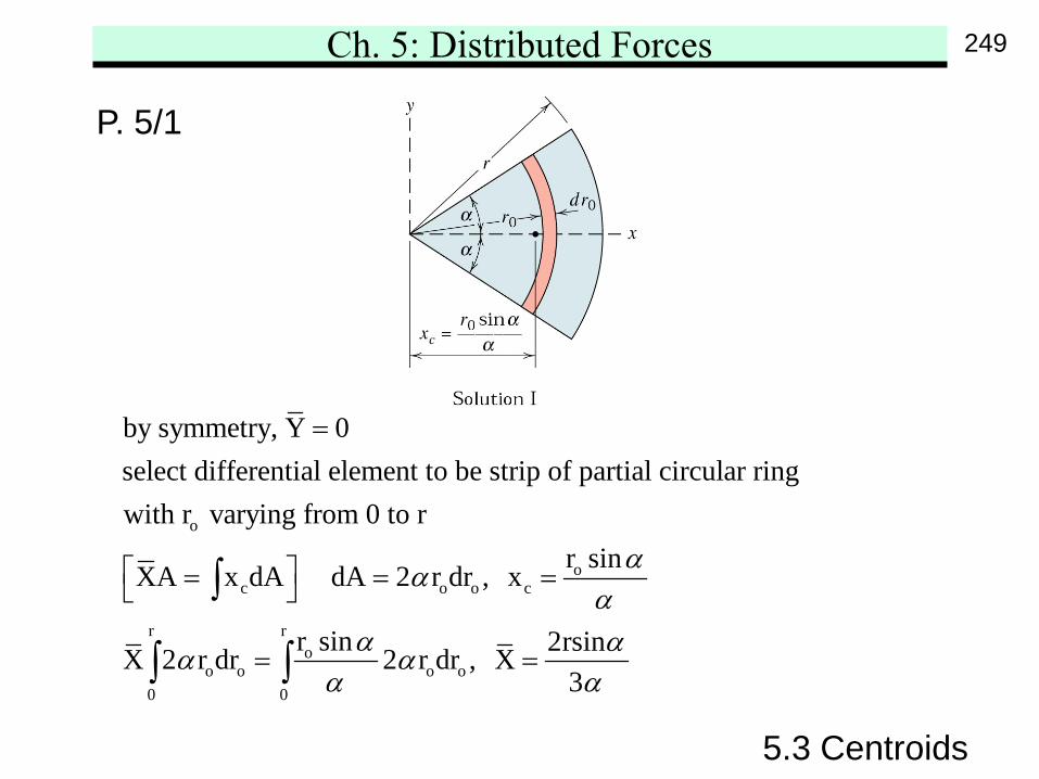
P. 5/1
o
oc o o c
r ro
o o o o0 0
by symmetry, Y 0select differential element to be strip of partial circular ringwith r varying from 0 to r
r sinXA x dA dA 2 r dr , x
r sin 2rsinX 2 r dr 2 r dr , X3
ααα
α αα αα α
=
= = =
= =
∫
∫ ∫
249
Ch. 5: Distributed Forces
5.3 Centroids
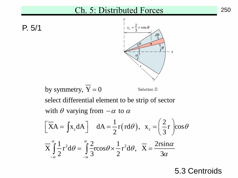
P. 5/1
( )c c
2 2
by symmetry, Y 0select differential element to be strip of sectorwith varying from to
1 2XA x dA dA r rd , x r cos2 3
1 2 1 2rsinX r d rcos r d , X2 3 2 3
α α
α α
θ α α
θ θ
αθ θ θα− −
=
−
= = =
= × =
∫
∫ ∫
250
Ch. 5: Distributed Forces
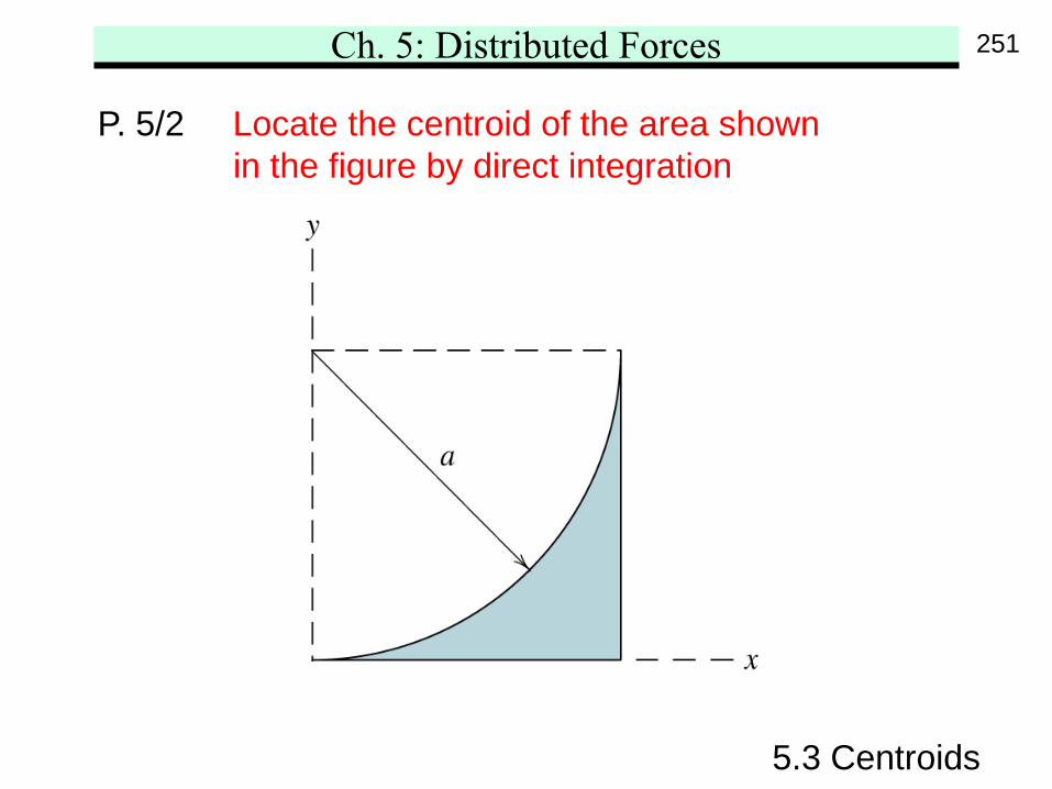
5.3 Centroids
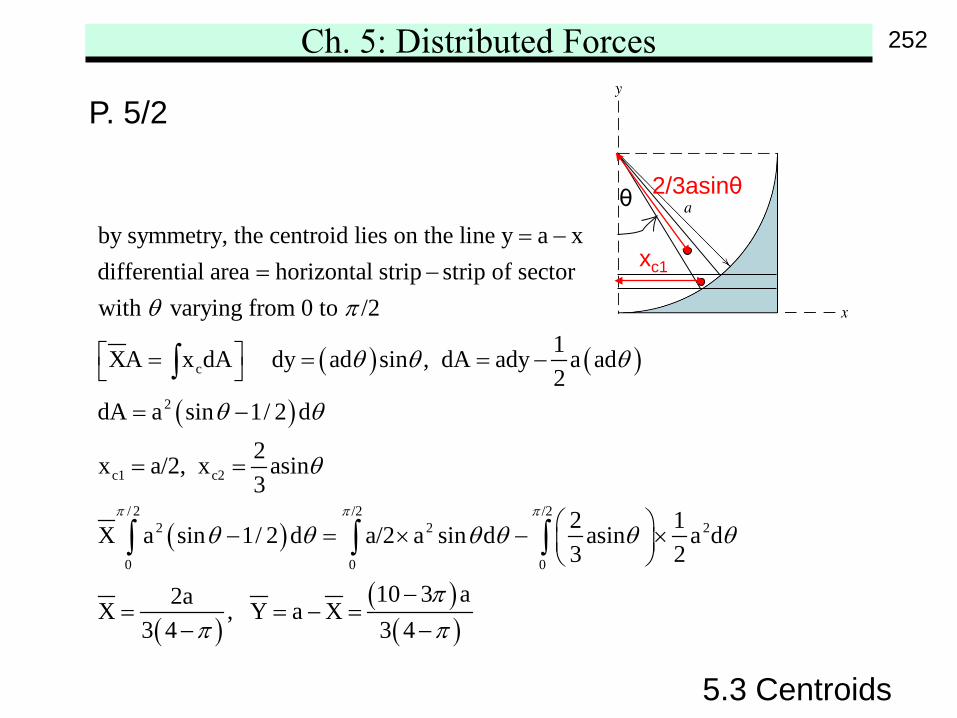
P. 5/2 Locate the centroid of the area shownin the figure by direct integration
251
Ch. 5: Distributed Forces
5.3 Centroids
P. 5/2
( ) ( )
( )c
2
c1 c2
by symmetry, the centroid lies on the line y a xdifferential area horizontal strip strip of sectorwith varying from 0 to /2
1XA x dA dy ad sin , dA ady a ad2
dA a sin 1/ 2 d2x a/2, x a3
θ π
θ θ θ
θ θ
= −= −
= = = −
= −
= =
∫
( )
( )( )( )
/ 2 /2 /22 2 2
0 0 0
sin
2 1X a sin 1/ 2 d a/2 a sin d asin a d3 2
10 3 a2aX , Y a X3 4 3 4
π π π
θ
θ θ θ θ θ θ
ππ π
− = × − ×
−= = − =
− −
∫ ∫ ∫
θ
xc1
2/3asinθ
252
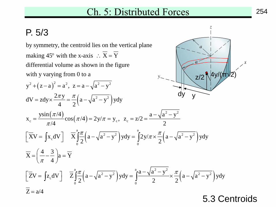
Ch. 5: Distributed Forces
5.3 Centroids
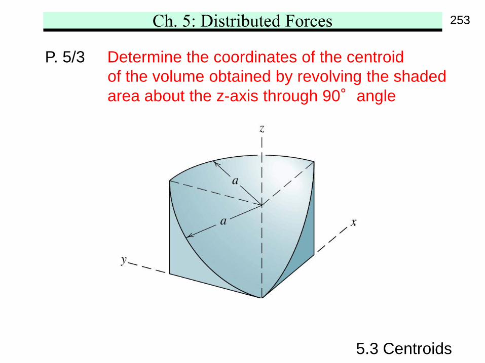
P. 5/3 Determine the coordinates of the centroidof the volume obtained by revolving the shadedarea about the z-axis through 90°angle
253
Ch. 5: Distributed Forces
5.3 Centroids
P. 5/3
( )
( )22 2 2 2
2 2
c
by symmetry, the centroid lies on the vertical plane
making 45 with the x-axis X Ydifferential volume as shown in the figurewith y varying from 0 to a
y z a a , z a a y2 ydV zdy a a y ydy
4 2
x
π π
° ∴ =
+ − = = − −
= × = − −
( ) ( )
( ) ( )
( ) ( )
2 2
c c
a a2 2 2 2
c0 0
a a 2 22 2 2 2
c0 0
ysin /4 a a ycos /4 2y/ y , z z/2
/4 2
XV x dV X a a y ydy 2y/ a a y ydy2 2
4 3X a Y4
a a yZV z dV Z a a y ydy a a y ydy
2 2 2
Z a/4
ππ π
ππ ππ
π
π π
− −= = = = =
= − − = × − −
= − =
− − = − − = × − −
=
∫ ∫ ∫
∫ ∫ ∫
4y/(π√2)z/2
ydy
254
Ch. 5: Distributed Forces
5.3 Centroids
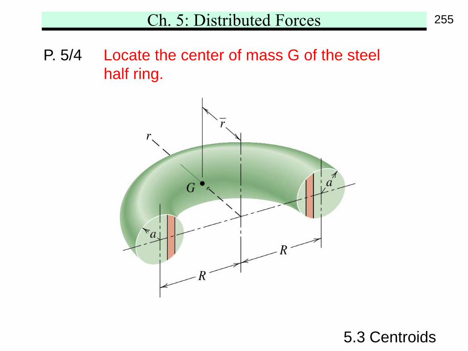
P. 5/4 Locate the center of mass G of the steelhalf ring.
255
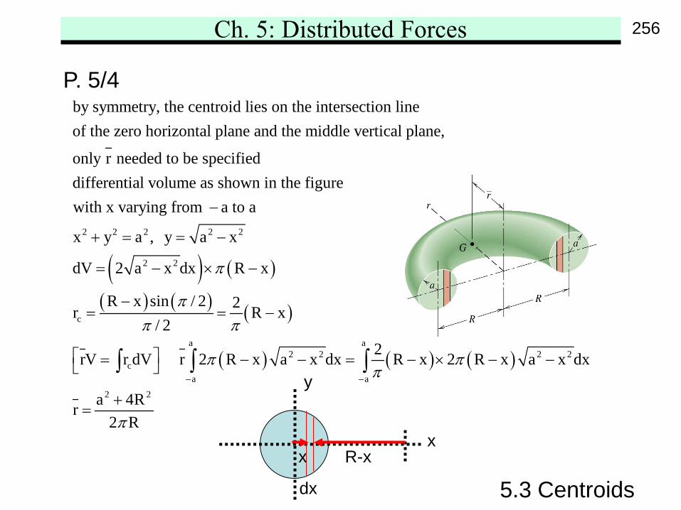
Ch. 5: Distributed Forces
5.3 Centroids
P. 5/4by symmetry, the centroid lies on the intersection lineof the zero horizontal plane and the middle vertical plane,
only r needed to be specifieddifferential volume as shown in the figurewith x varying
( ) ( )
( ) ( ) ( )
( ) ( ) ( )
2 2 2 2 2
2 2
c
a a2 2 2 2
ca a
2 2
from a to a
x y a , y a x
dV 2 a x dx R x
R x sin / 2 2r R x/ 2
2rV r dV r 2 R x a x dx R x 2 R x a x dx
a 4Rr2 R
π
ππ π
π ππ
π
− −
−
+ = = −
= − × −
−= = −
= − − = − × − −
+=
∫ ∫ ∫
x
y
x
dx
R-x
256
Ch. 5: Distributed Forces
5.3 Composite Bodies and Figures
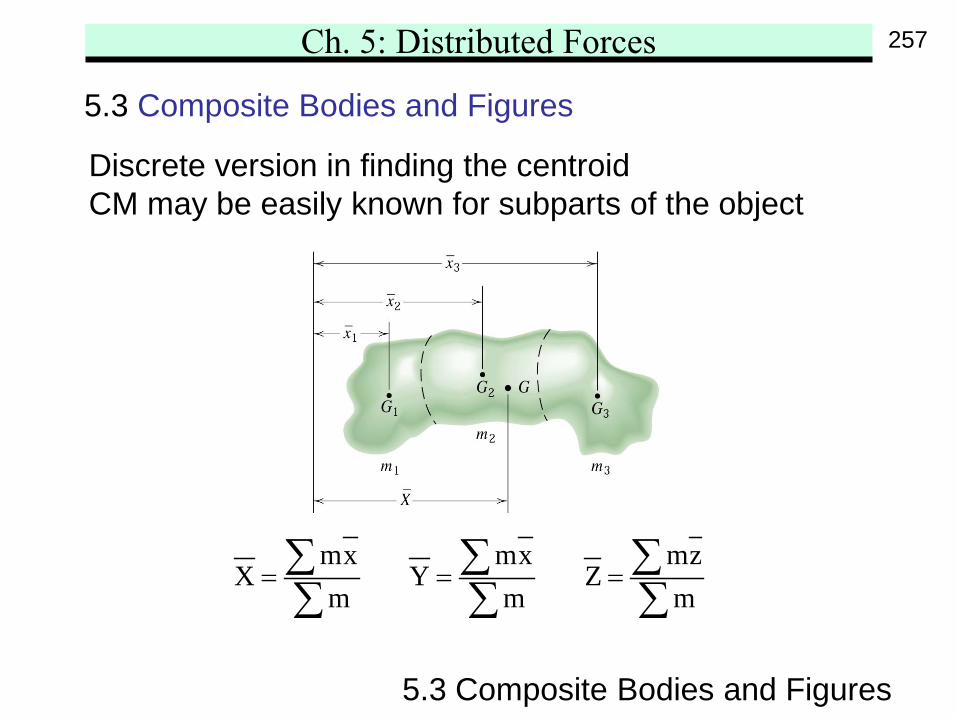
5.3 Composite Bodies and Figures
Discrete version in finding the centroidCM may be easily known for subparts of the object
mx mx mzX Y Z
m m m= = =∑ ∑ ∑∑ ∑ ∑
257
Ch. 5: Distributed Forces
5.3 Composite Bodies and Figures
Depending on the geometry and the density ofthe object, mass m may be replaced by l, A, or V.
Addition vs. Subtraction
Table consultation
Systematic tabulation of i ci i i cim , r , m , m r∑ ∑
258
Ch. 5: Distributed Forces
5.3 Composite Bodies and Figures
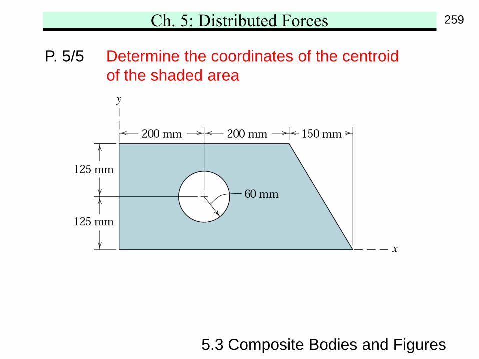
P. 5/5 Determine the coordinates of the centroidof the shaded area
259
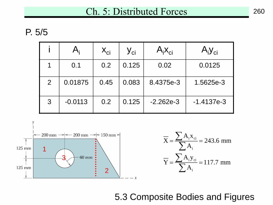
Ch. 5: Distributed Forces
5.3 Composite Bodies and Figures
P. 5/5
i Ai xci yci Aixci Aiyci
1 0.1 0.2 0.125 0.02 0.0125
2 0.01875 0.45 0.083 8.4375e-3 1.5625e-3
3 -0.0113 0.2 0.125 -2.262e-3 -1.4137e-3
i ci
i
i ci
i
A xX 243.6 mm
A
A yY 117.7 mm
A
= =
= =
∑∑∑∑
13
2
260
Ch. 5: Distributed Forces
5.3 Composite Bodies and Figures
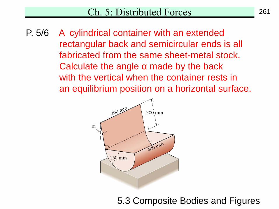
P. 5/6 A cylindrical container with an extendedrectangular back and semicircular ends is allfabricated from the same sheet-metal stock.Calculate the angle α made by the backwith the vertical when the container rests inan equilibrium position on a horizontal surface.
261
Ch. 5: Distributed Forces
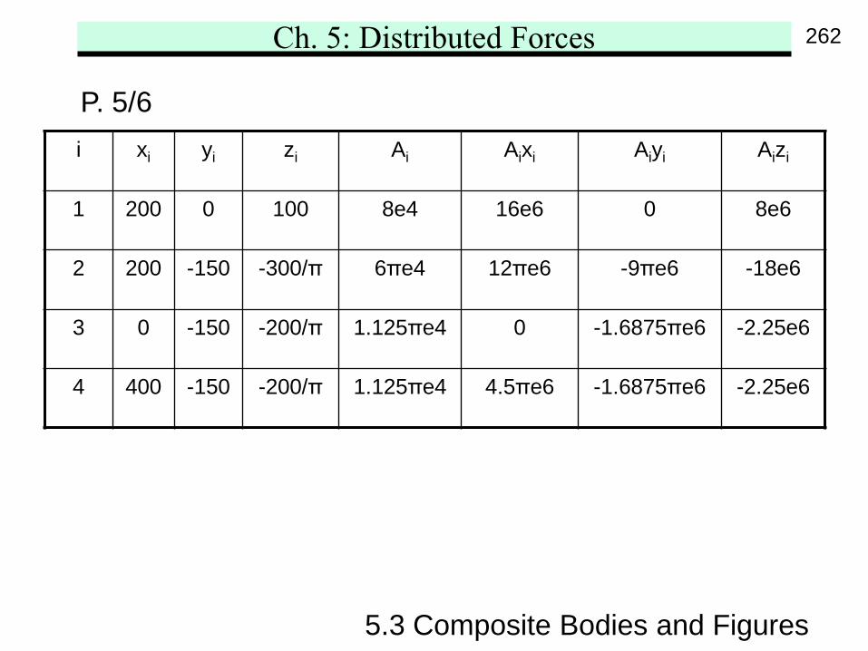
5.3 Composite Bodies and Figures
P. 5/6i xi yi zi Ai Aixi Aiyi Aizi
1 200 0 100 8e4 16e6 0 8e6
2 200 -150 -300/π 6πe4 12πe6 -9πe6 -18e6
3 0 -150 -200/π 1.125πe4 0 -1.6875πe6 -2.25e6
4 400 -150 -200/π 1.125πe4 4.5πe6 -1.6875πe6 -2.25e6
262
Ch. 5: Distributed Forces
5.3 Composite Bodies and Figures
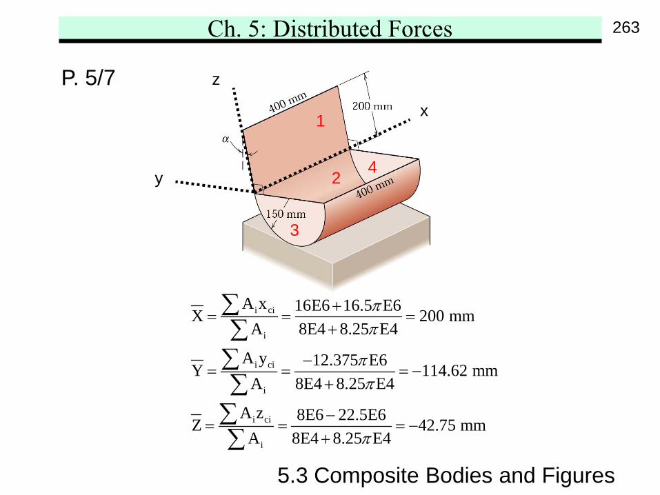
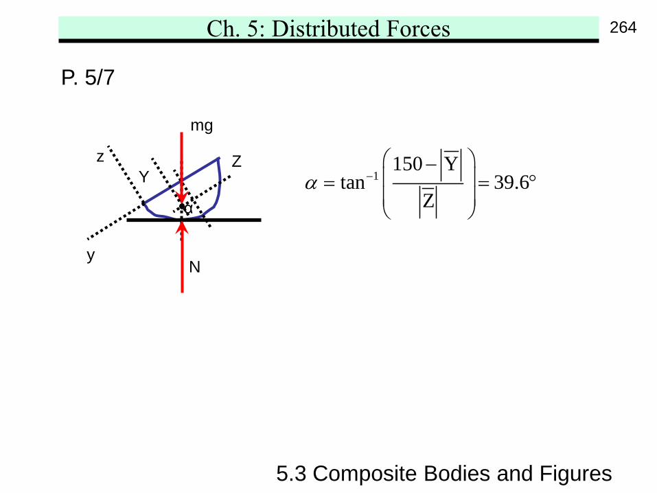
P. 5/7
i ci
i
i ci
i
i ci
i
A x 16E6 16.5 E6X 200 mmA 8E4 8.25 E4
A y 12.375 E6Y 114.62 mmA 8E4 8.25 E4
A z 8E6 22.5E6Z 42.75 mmA 8E4 8.25 E4
ππ
ππ
π
+= = =
+
−= = = −
+
−= = = −
+
∑∑∑∑∑∑
1
2
3
4
x
y
z
263
Ch. 5: Distributed Forces
5.3 Composite Bodies and Figures
P. 5/7
1150 Y
tan 39.6Z
α − − = = ° α
y
z
mg
YZ
N
264
Ch. 5: Distributed Forces
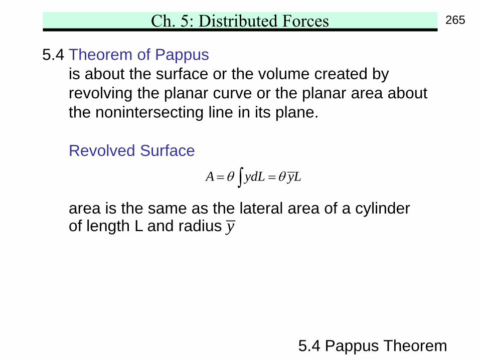
5.4 Theorem of Pappusis about the surface or the volume created byrevolving the planar curve or the planar area aboutthe nonintersecting line in its plane.
Revolved Surface
area is the same as the lateral area of a cylinderof length L and radius
5.4 Pappus Theorem
A ydL yLθ θ= =∫
y
265
Ch. 5: Distributed Forces
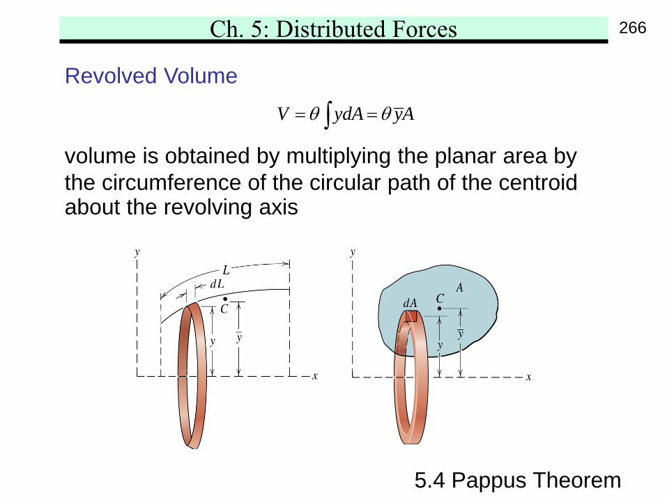
Revolved Volume
volume is obtained by multiplying the planar area bythe circumference of the circular path of the centroidabout the revolving axis
5.4 Pappus Theorem
V ydA yAθ θ= =∫
266
Ch. 5: Distributed Forces
Usage1. determining the area or volume of revolution2. find the centroid of planar curve or planar area
when the corresponding area or volume are known
5.4 Pappus Theorem
267
Ch. 5: Distributed Forces
5.4 Pappus Theorem
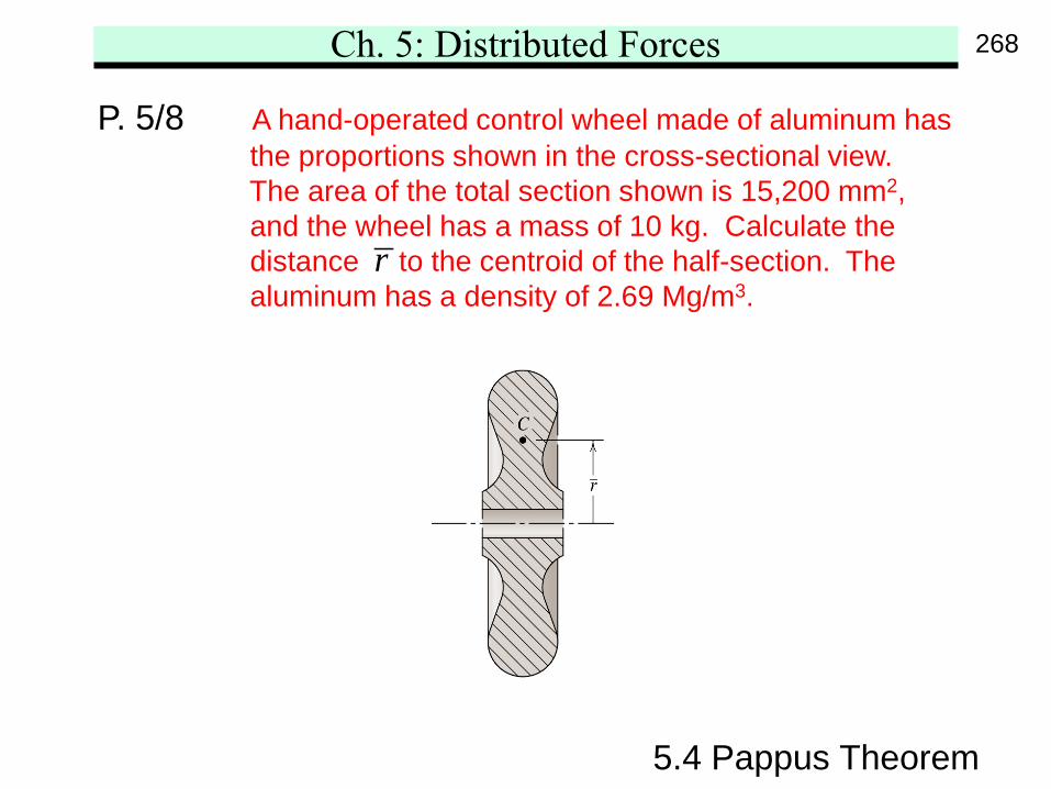
P. 5/8 A hand-operated control wheel made of aluminum hasthe proportions shown in the cross-sectional view.The area of the total section shown is 15,200 mm2,and the wheel has a mass of 10 kg. Calculate thedistance to the centroid of the half-section. Thealuminum has a density of 2.69 Mg/m3.
r
268
Ch. 5: Distributed Forces
5.4 Pappus Theorem
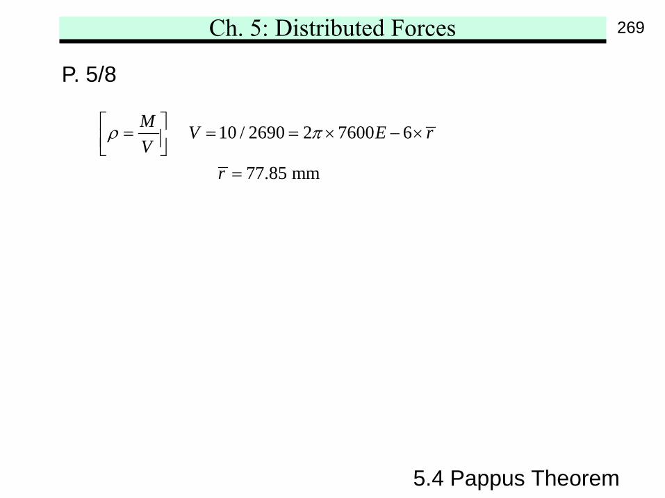
P. 5/8
10 / 2690 2 7600 6
77.85 mm
M V E rV
r
ρ π = = = × − × =
269
Ch. 5: Distributed Forces
5.4 Pappus Theorem
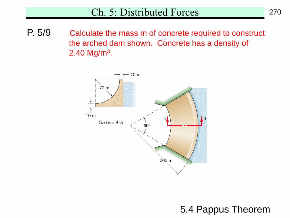
P. 5/9 Calculate the mass m of concrete required to constructthe arched dam shown. Concrete has a density of2.40 Mg/m3.
270
Ch. 5: Distributed Forces
5.4 Pappus Theorem
P. 5/9
( ) 2
2
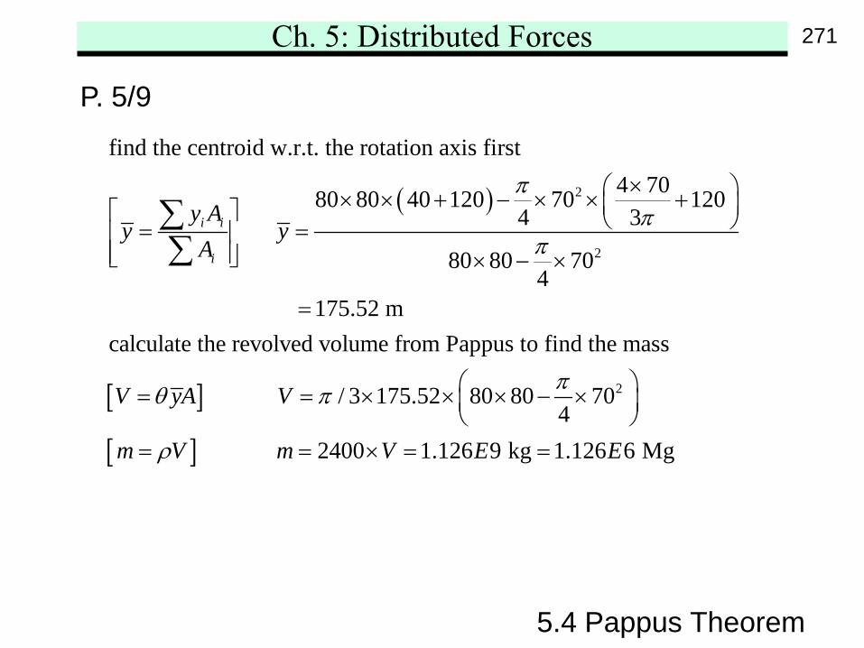
find the centroid w.r.t. the rotation axis first4 7080 80 40 120 70 120
4 3 80 80 70
4 175.52 mcalculate the revolved volume from Pap
i i
i
y Ay y
A
ππ
π
× × × + − × × + = = × − ×
=
∑∑
[ ]
[ ]
2
pus to find the mass
/ 3 175.52 80 80 704
2400 1.126 9 kg 1.126 6 Mg
V yA V
m V m V E E
πθ π
ρ
= = × × × − ×
= = × = =
271
Ch. 5: Distributed Forces
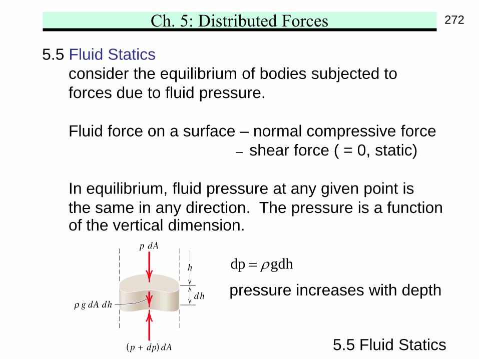
5.5 Fluid Staticsconsider the equilibrium of bodies subjected toforces due to fluid pressure.
Fluid force on a surface – normal compressive force– shear force ( = 0, static)
In equilibrium, fluid pressure at any given point isthe same in any direction. The pressure is a functionof the vertical dimension.
5.5 Fluid Statics
dp gdhρ=
pressure increases with depth
272
Ch. 5: Distributed Forces
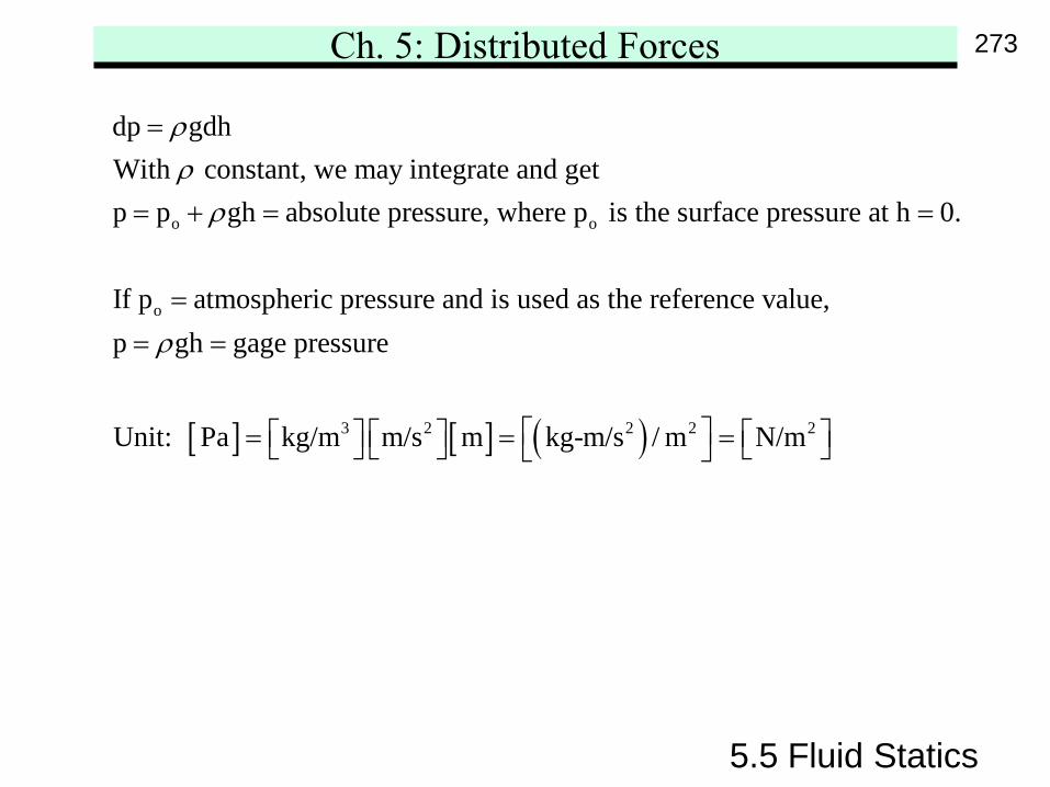
5.5 Fluid Statics
o o
o
dp gdhWith constant, we may integrate and getp p gh absolute pressure, where p is the surface pressure at h 0.
If p atmospheric pressure and is used as the reference value,p gh gage pressure
Uni
ρρ
ρ
ρ
=
= + = =
== =
[ ] [ ] ( )3 2 2 2 2t: Pa kg/m m/s m kg-m/s / m N/m = = =
273
Ch. 5: Distributed Forces
5.5 Fluid Statics
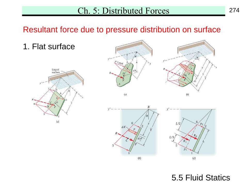
Resultant force due to pressure distribution on surface
1. Flat surface
274
Ch. 5: Distributed Forces
5.5 Fluid Statics
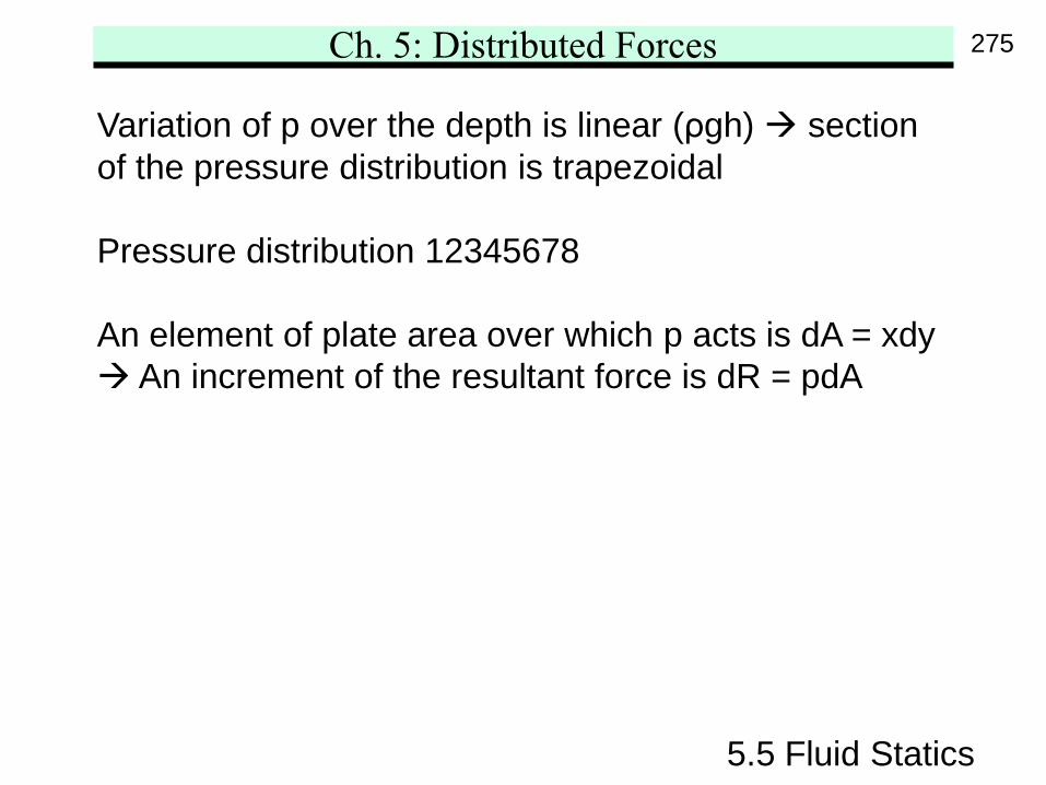
Variation of p over the depth is linear (ρgh) sectionof the pressure distribution is trapezoidal
Pressure distribution 12345678
An element of plate area over which p acts is dA = xdy An increment of the resultant force is dR = pdA
275
Ch. 5: Distributed Forces
5.5 Fluid Statics
( ) ( )
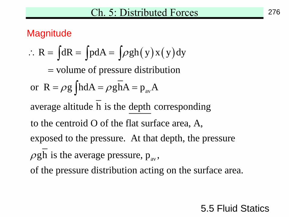
av
R dR pdA gh y x y dy
volume of pressure distribution
or R g hdA ghA p A
average altitude h is the depth corresponding
to the centroid O of the flat surface area, A,exposed to the pressure. At
ρ
ρ ρ
∴ = = =
=
= = =
∫ ∫ ∫
∫
av
that depth, the pressure
gh is the average pressure, p ,of the pressure distribution acting on the surface area.ρ
Magnitude
276
Ch. 5: Distributed Forces
5.5 Fluid Statics
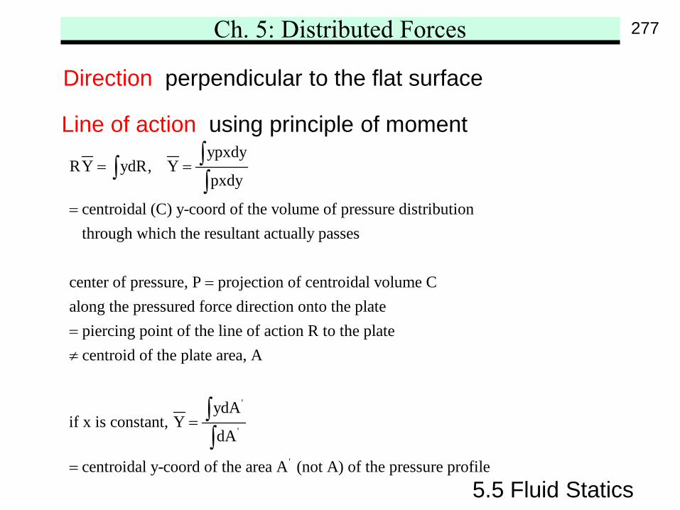
ypxdyRY ydR, Y
pxdy
centroidal (C) y-coord of the volume of pressure distribution through which the resultant actually passes
center of pressure, P projection of centroidal volume Calong the pre
= =
=
=
∫∫ ∫
'
'
'
ssured force direction onto the platepiercing point of the line of action R to the platecentroid of the plate area, A
ydAif x is constant, Y
dA
centroidal y-coord of the area A (not A) of the pr
=≠
=
=
∫∫
essure profile
Direction perpendicular to the flat surface
Line of action using principle of moment
277
Ch. 5: Distributed Forces
5.5 Fluid Statics
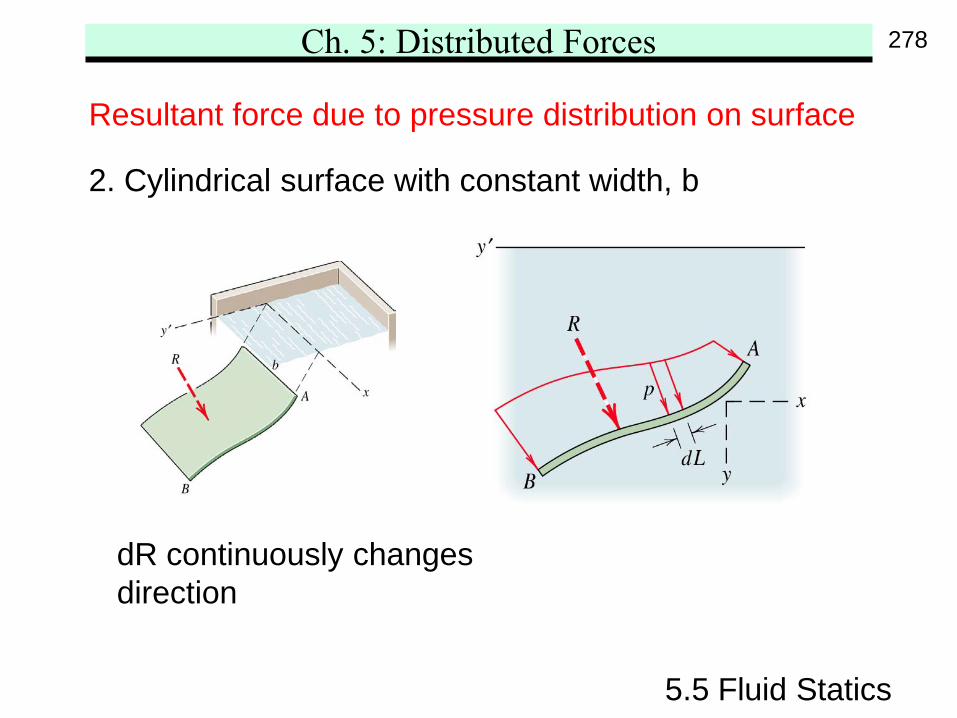
Resultant force due to pressure distribution on surface
2. Cylindrical surface with constant width, b
dR continuously changesdirection
278
Ch. 5: Distributed Forces
5.5 Fluid Statics
( ) ( )x yx y
R volume of pressure distribution ghA
h depth corresponding to the centroid O of the curve AB
R b pdL b pdy, R b pdL b pdx
ρ= =
=
= = = =∫ ∫ ∫ ∫
Magnitude
Direction( )1
y xtan R / Rθ −=
Line of action
y x
y x
xdR xpdx ydR ypdyX , Y
dR pdx dR pdy
at centroid of volume of pressure distribution
= = = =∫ ∫ ∫ ∫∫ ∫ ∫ ∫
279
Ch. 5: Distributed Forces
5.5 Fluid Statics
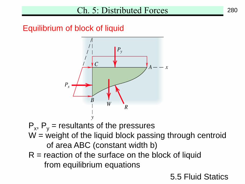
Equilibrium of block of liquid
Px, Py = resultants of the pressuresW = weight of the liquid block passing through centroid
of area ABC (constant width b)R = reaction of the surface on the block of liquid
from equilibrium equations
280
Ch. 5: Distributed Forces
5.5 Fluid Statics
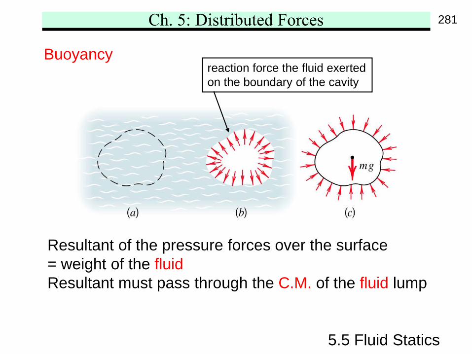
Buoyancyreaction force the fluid exertedon the boundary of the cavity
Resultant of the pressure forces over the surface= weight of the fluidResultant must pass through the C.M. of the fluid lump
281
Ch. 5: Distributed Forces
5.5 Fluid Statics
Buoyancy
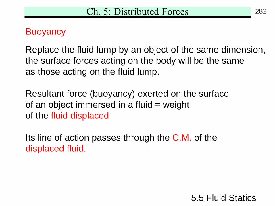
Replace the fluid lump by an object of the same dimension,the surface forces acting on the body will be the sameas those acting on the fluid lump.
Resultant force (buoyancy) exerted on the surfaceof an object immersed in a fluid = weightof the fluid displaced
Its line of action passes through the C.M. of thedisplaced fluid.
282
Ch. 5: Distributed Forces
5.5 Fluid Statics
Buoyancy
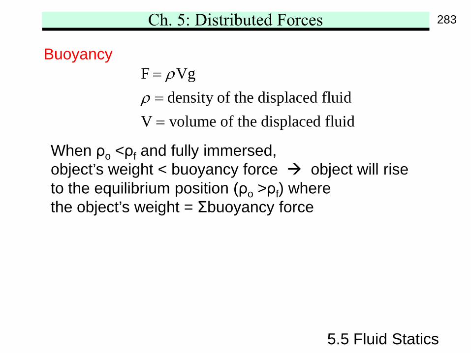
When ρo <ρf and fully immersed,object’s weight < buoyancy force object will riseto the equilibrium position (ρo >ρf) wherethe object’s weight = Σbuoyancy force
F Vgdensity of the displaced fluid
V volume of the displaced fluid
ρρ===
283
Ch. 5: Distributed Forces
5.5 Fluid Statics
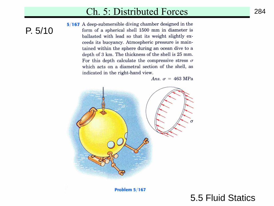
P. 5/10
284
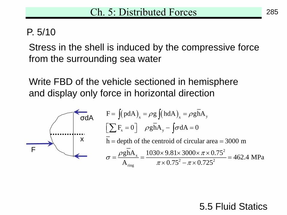
Ch. 5: Distributed Forces
5.5 Fluid Statics
P. 5/10Stress in the shell is induced by the compressive forcefrom the surrounding sea water
Write FBD of the vehicle sectioned in hemisphereand display only force in horizontal direction
F
σdA ( ) ( ) yx x
x y
2x
2 2ring
F pdA g hdA ghA
F 0 ghA dA 0
h depth of the centroid of circular area 3000 m
ghA 1030 9.81 3000 0.75 462.4 MPaA 0.75 0.725
ρ ρ
ρ σ
ρ πσπ π
= = =
= − =
= =
× × × ×= = =
× − ×
∫ ∫∑ ∫
x
285
Ch. 5: Distributed Forces
5.5 Fluid Statics
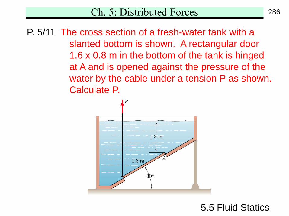
P. 5/11 The cross section of a fresh-water tank with aslanted bottom is shown. A rectangular door1.6 x 0.8 m in the bottom of the tank is hingedat A and is opened against the pressure of thewater by the cable under a tension P as shown.Calculate P.
286
Ch. 5: Distributed Forces
5.5 Fluid Statics
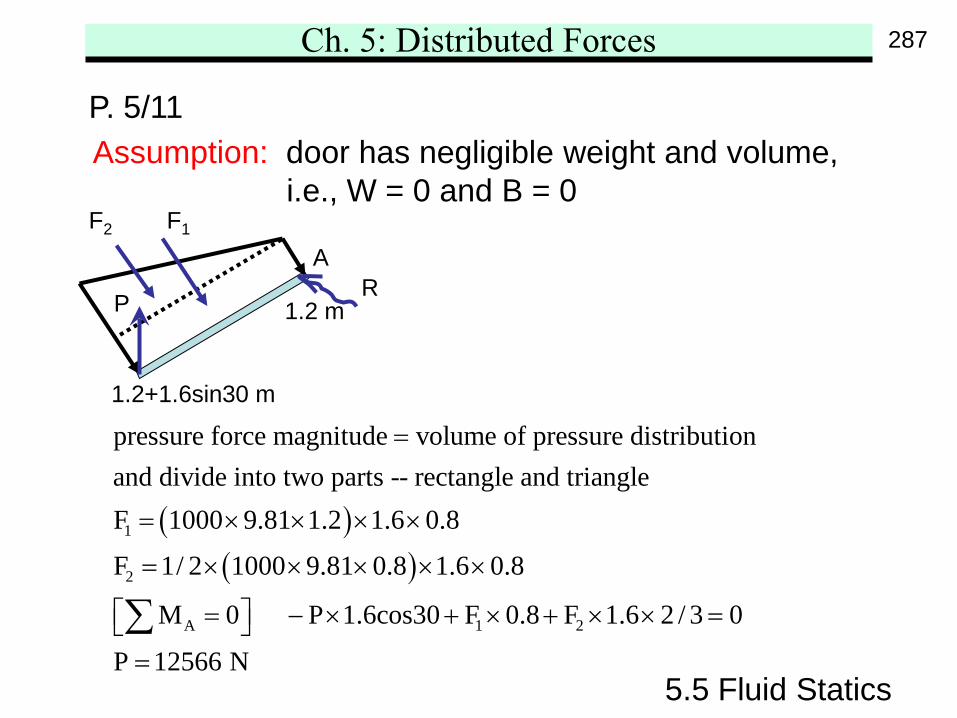
P. 5/11Assumption: door has negligible weight and volume,
i.e., W = 0 and B = 0
( )( )
1
2
A 1 2
pressure force magnitude volume of pressure distributionand divide into two parts -- rectangle and triangleF 1000 9.81 1.2 1.6 0.8
F 1/ 2 1000 9.81 0.8 1.6 0.8
M 0 P 1.6cos30 F 0.8 F 1.6 2 /
=
= × × × ×
= × × × × ×
= − × + × + × × ∑ 3 0
P 12566 N
=
=
AR
F1F2
P 1.2 m
1.2+1.6sin30 m
287
Ch. 5: Distributed Forces
5.5 Fluid Statics
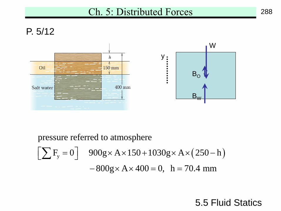
P. 5/12
( )y
pressure referred to atmosphere
F 0 900g A 150 1030g A 250 h
800g A 400 0, h 70.4 mm
= × × + × × − − × × = =
∑
yW
BO
BW
288
Ch. 5: Distributed Forces
5.5 Fluid Statics
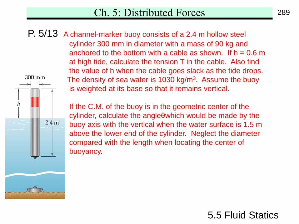
P. 5/13 A channel-marker buoy consists of a 2.4 m hollow steelcylinder 300 mm in diameter with a mass of 90 kg andanchored to the bottom with a cable as shown. If h = 0.6 mat high tide, calculate the tension T in the cable. Also findthe value of h when the cable goes slack as the tide drops.
The density of sea water is 1030 kg/m3. Assume the buoyis weighted at its base so that it remains vertical.
If the C.M. of the buoy is in the geometric center of thecylinder, calculate the angleθwhich would be made by thebuoy axis with the vertical when the water surface is 1.5 mabove the lower end of the cylinder. Neglect the diametercompared with the length when locating the center ofbuoyancy.
289
Ch. 5: Distributed Forces
5.5 Fluid Statics
P. 5/13
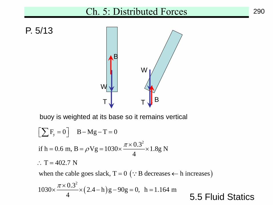
W
T B
W
T
B
buoy is weighted at its base so it remains vertical
( )
( )
y
2
2
F 0 B Mg T 0
0.3if h 0.6 m, B Vg 1030 1.8g N4
T 402.7 Nwhen the cable goes slack, T 0 B decreases h increases
0.31030 2.4 h g 90g 0, h 1.164 m4
πρ
π
= − − = ×
= = = × ×
∴ =
= ←
×× × − − = =
∑
290
Ch. 5: Distributed Forces
5.5 Fluid Statics
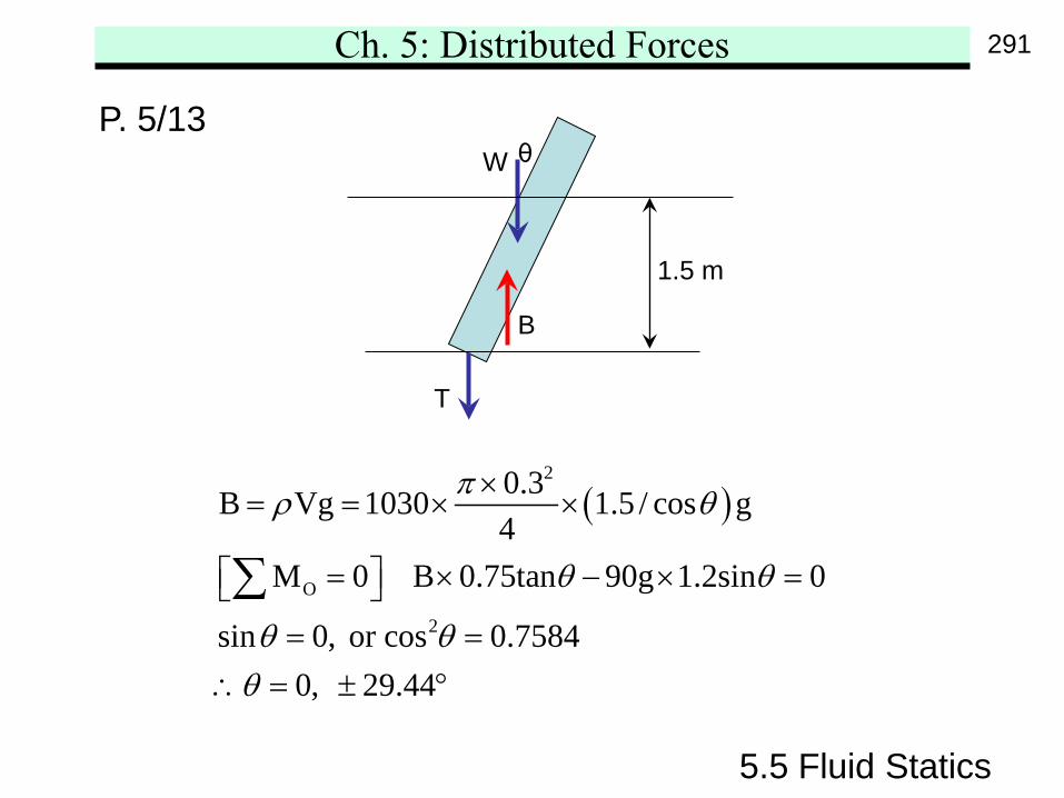
P. 5/13W
T
B
( )2
O
2
0.3B Vg 1030 1.5 / cos g4
M 0 B 0.75tan 90g 1.2sin 0
sin 0, or cos 0.75840, 29.44
πρ θ
θ θ
θ θθ
×= = × ×
= × − × = = =
∴ = ± °
∑
1.5 m
θ
291
Ch. 5: Distributed Forces
5.5 Fluid Statics
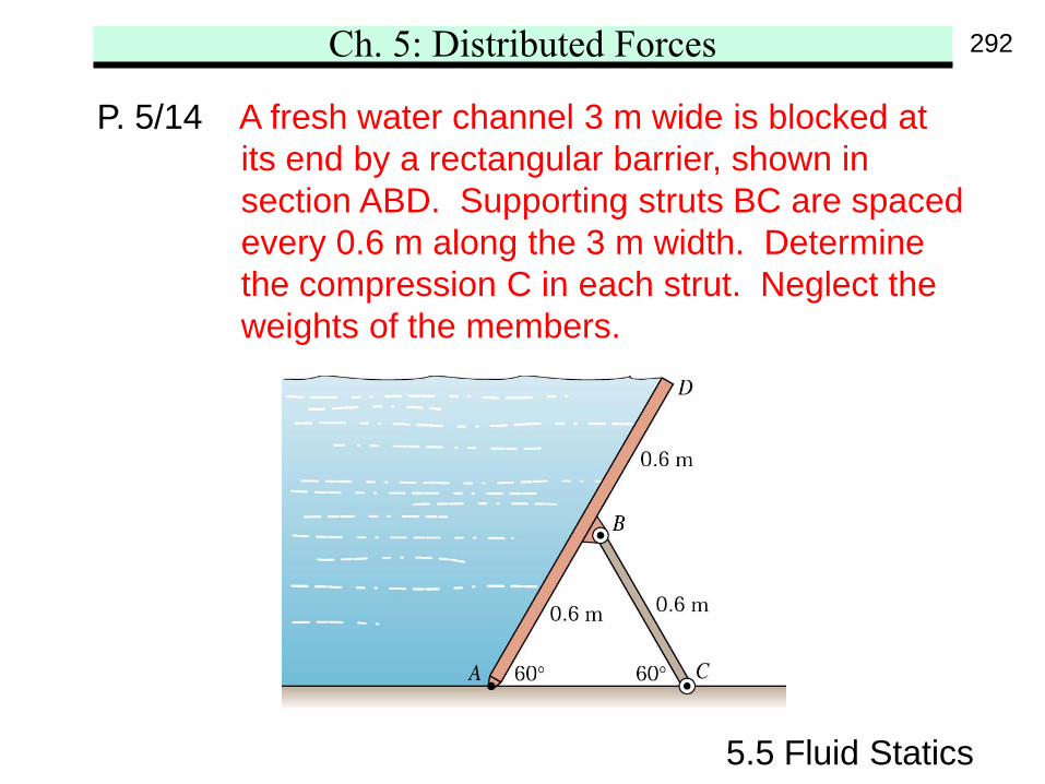
P. 5/14 A fresh water channel 3 m wide is blocked atits end by a rectangular barrier, shown insection ABD. Supporting struts BC are spacedevery 0.6 m along the 3 m width. Determinethe compression C in each strut. Neglect theweights of the members.
292
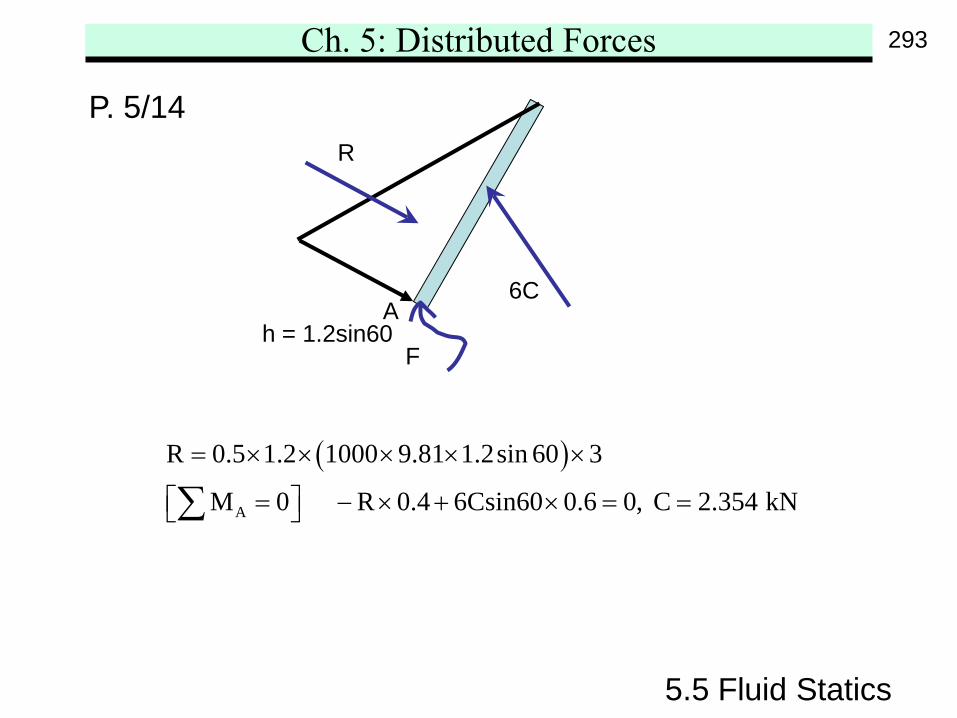
Ch. 5: Distributed Forces
5.5 Fluid Statics
P. 5/14
( )A
R 0.5 1.2 1000 9.81 1.2sin 60 3
M 0 R 0.4 6Csin60 0.6 0, C 2.354 kN
= × × × × ×
= − × + × = = ∑
6C
F
R
Ah = 1.2sin60
293
Ch. 5: Distributed Forces
5.5 Fluid Statics
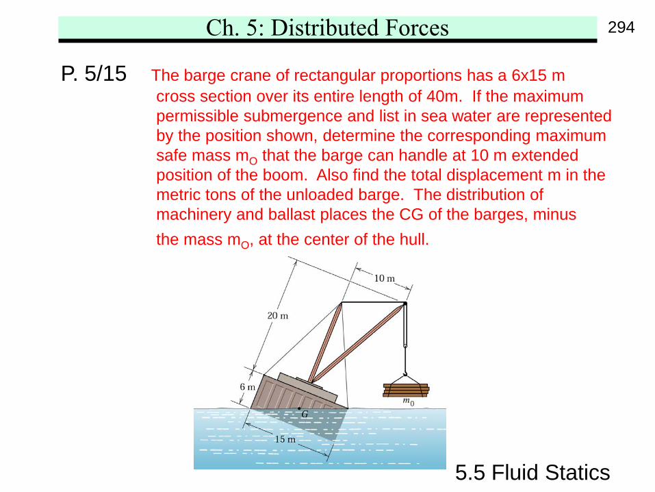
P. 5/15 The barge crane of rectangular proportions has a 6x15 mcross section over its entire length of 40m. If the maximumpermissible submergence and list in sea water are representedby the position shown, determine the corresponding maximumsafe mass mO that the barge can handle at 10 m extendedposition of the boom. Also find the total displacement m in themetric tons of the unloaded barge. The distribution ofmachinery and ballast places the CG of the barges, minusthe mass mO, at the center of the hull.
294
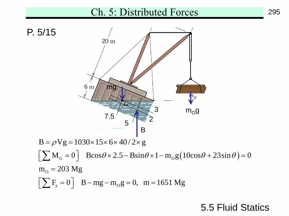
Ch. 5: Distributed Forces
5.5 Fluid Statics
P. 5/15
( )G O
O
y O
B Vg 1030 15 6 40 / 2 g
M 0 Bcos 2.5 Bsin 1 m g 10cos 23sin 0
m 203 Mg
F 0 B mg m g 0, m 1651 Mg
ρ
θ θ θ θ
= = × × × ×
= × − × − + = =
= − − = =
∑
∑
mOg
mg
B2
3
57.5
295
Ch. 5: Distributed Forces
5.5 Fluid Statics
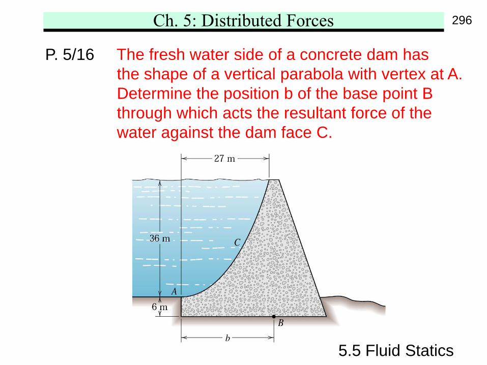
P. 5/16 The fresh water side of a concrete dam hasthe shape of a vertical parabola with vertex at A.Determine the position b of the base point Bthrough which acts the resultant force of thewater against the dam face C.
296
Ch. 5: Distributed Forces
5.5 Fluid Statics
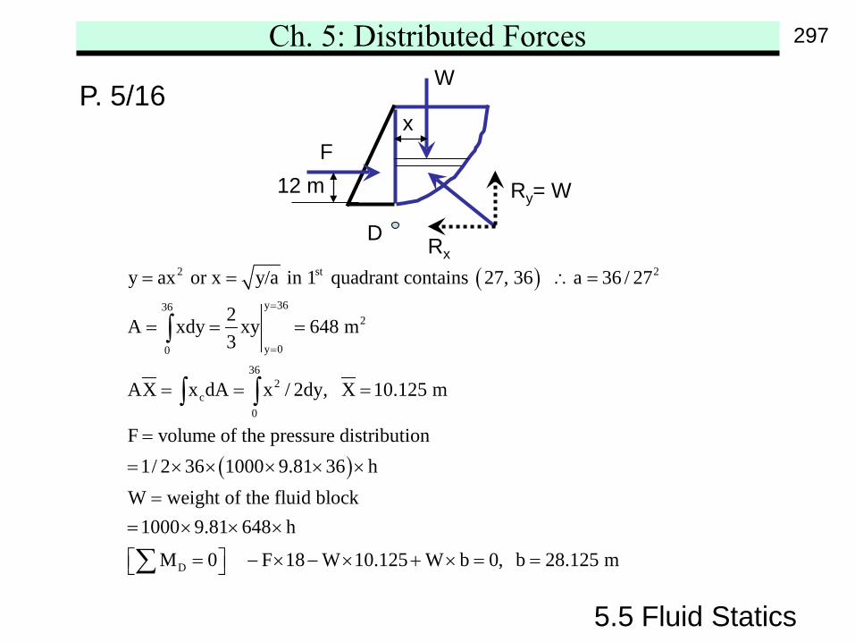
P. 5/16
( )
( )
2 st 2
y 36362
y 00
362
c0
y ax or x y/a in 1 quadrant contains 27, 36 a 36 / 27
2A xdy xy 648 m3
AX x dA x / 2dy, X 10.125 m
F volume of the pressure distribution1/ 2 36 1000 9.81 36 h
W weight of the fluid bl
=
=
= = ∴ =
= = =
= = =
=
= × × × × ×
=
∫
∫ ∫
D
ock1000 9.81 648 h
M 0 F 18 W 10.125 W b 0, b 28.125 m
= × × ×
= − × − × + × = = ∑
Rx
Ry= W
F
W
x
12 m
D
297
Ch. 5: Distributed Forces
5.5 Fluid Statics
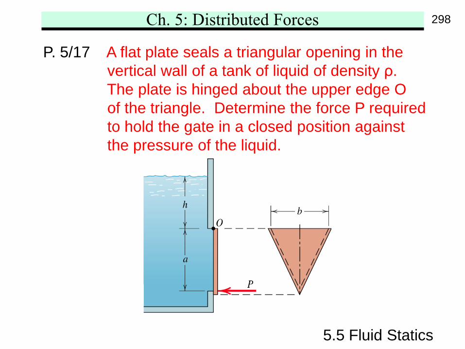
P. 5/17 A flat plate seals a triangular opening in thevertical wall of a tank of liquid of density ρ.The plate is hinged about the upper edge Oof the triangle. Determine the force P requiredto hold the gate in a closed position againstthe pressure of the liquid.
298
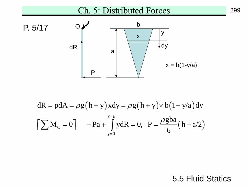
Ch. 5: Distributed Forces
5.5 Fluid Statics
P. 5/17
( ) ( ) ( )
( )y a
Oy 0
dR pdA g h y xdy g h y b 1 y/a dy
gbaM 0 Pa ydR 0, P h a/26
ρ ρ
ρ=
=
= = + = + × −
= − + = = + ∑ ∫
y
dyx
x = b(1-y/a)
b
a
O
dR
P
299