Embed Size (px)
Citation preview

Pub
licat
ion
Num
er Q
S00
5CF
W10

2
2
Power Connections:
The CFW10 Quick Start Guide is a supplement to help get the CFW10 started quickly using the most common installationand configuration options. This CFW10 Quick Start Guide is not meant to replace the CFW10 User’s Manual. For detailedinstructions, safety precautions, proper mounting, installation, configuration, and operation please refer to the CFW10User’s Guide. Warning: Only qualified personnel should plan or implement the installation, start-up, operation andmaintenance of this equipment. Personnel must read the entire CFW10 User’s Guide before attempting to install, operateor troubleshoot the CFW10.
Figure 1 - Power and Grounding Connections
Basic Wiring:
1. Mount the CFW10 to a flat vertical surface.2. Connect the incoming single phase power leads to the L/L1 and N/L2 connections on the power terminal and
connect the GROUND lead to PE on the power terminal (Refer to Figure 1).3. Connect the motor leads to the U, V, and W connections on the power terminal and connect the GROUND lead to
PE on the power terminal (Refer to Figure 1). Note: Only three-phase AC motors can be used.4. Apply power to the CFW10 drive. The drive will run self diagnostics and if no problems are found it will display
“rdY”. Note: New CFW10 drives are shipped with parameters preset to factory defaults. If you need to reloadfactory defaults at any time, first set password parameter P000=5 then set factory default parameter P204=5.
Keypad Start/Stop (Local Mode): This operation mode is recommended for users who are operating the drive for
the first time without additional control connections.
1. Press the start key. The motor will accelerate from 0.0 to 3.00 Hz (minimum speed P133), in the clockwisedirection. Note: If the direction of rotation is not correct, switch off the drive and wait until the capacitors dischargecompletely (as long as 10 minutes) and then swap any two wires at the motor output.
2. Press the key and hold it to increase motor speed (maximum speed P134). Note: On Plus versions use thekeypad potentiometer located on the bottom right of the keypad to adjust speed.
3. Press the stop key. The motor decelerates to 0.0Hz and stops with a display of “rdY”.

3
3
Keypad Operation and Parameter Setup:
Figure 2 – Keypad Operation
Display Display Description
rdY Drive is ready to be enabled.
Sub Power supply voltage too low for drive operation.
dcb Drive in DC braking mode.
EPP Drive is loading factory setting.
Note: Plus versions of the CFW10 have aspeed potentiometer on the lower rightside of the keypad which is used toincrease/decrease speed.
Key Description
Switches the display betweenparameter number andcontent.
Increases Speed (frequency)and Parameternumber/content
Decreases Speed andParameter number/content
Starts/Stops the drive via theacceleration/decelerationramp and resets the driveafter a fault.
The CFW10 does not require parameter programming prior to start up and is ready to operate with the factory defaultsettings. A parameter example is given below to familiarize the user with parameter navigation, viewing, andprogramming.
Action LED Display Description
After power is applied to the drive, the display showsthe following message.
Drive is ready to be started.
Press the key to view parameter number. The redLED on the keypad will light to indicate “parameternumber”.
Press the or arrow keys to select aparameter.
Select the desired parameter. Thisexample uses parameter numberP100 (Acceleration Time).
Press the key to view the value of the parameter.The green LED on the keypad will light to indicate“parameter value”.
This is the numerical valueassociated with the parameter. Forthis example then P100=5.0therefore the acceleration time is setfor 5 seconds.
Press the or arrow keys to change theparameter value.
Set the new desired value. In thisexample the acceleration time hasbeen increased to 6.1 seconds.Note: To change parameter valuesyou must first set the accessparameter P000=5. Some parameterchanges require the drive bestopped first.
Press the key to store the new value.The new value for P100(acceleration time) is stored inmemory.
Repeat this procedure for other parameters that mayneed to be changed.
LED Display –
indicates fault
codes, inverter
status, parameter
number and value.
Green LED –
When lit the
display indicates
the parameter
value.
Red LED –
When lit the
display indicates
the parameter
number.
4
4
Keypad Start/Stop (Local Mode) continued:
4. If parameters were accessed or changed under Parameter Setup then the last parameter number or value will be
displayed. Scroll up or down with the or keys to the read only parameter P002 (Frequency
Proportional Value for Speed) and press the key to see the value.
5. Return to step 1 and press the start key to start the drive.
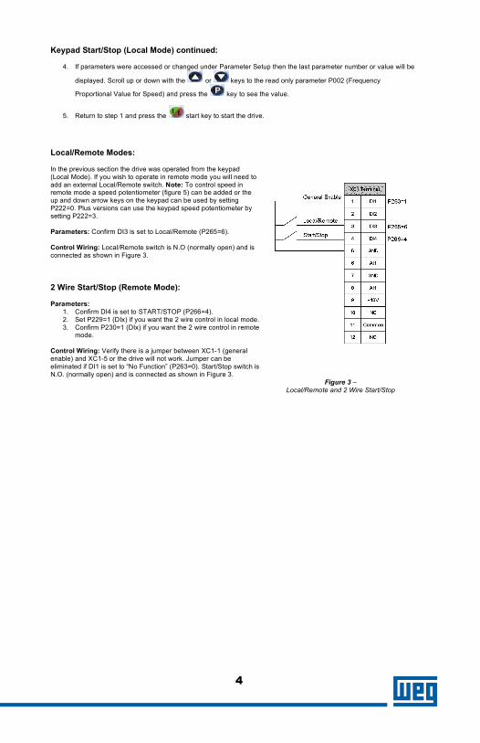
Local/Remote Modes:
In the previous section the drive was operated from the keypad(Local Mode). If you wish to operate in remote mode you will need toadd an external Local/Remote switch. Note: To control speed inremote mode a speed potentiometer (figure 5) can be added or theup and down arrow keys on the keypad can be used by settingP222=0. Plus versions can use the keypad speed potentiometer bysetting P222=3.
Parameters: Confirm DI3 is set to Local/Remote (P265=6).
Control Wiring: Local/Remote switch is N.O (normally open) and isconnected as shown in Figure 3.
2 Wire Start/Stop (Remote Mode):
Parameters:1. Confirm DI4 is set to START/STOP (P266=4).2. Set P229=1 (DIx) if you want the 2 wire control in local mode.3. Confirm P230=1 (DIx) if you want the 2 wire control in remote
mode.
Control Wiring: Verify there is a jumper between XC1-1 (generalenable) and XC1-5 or the drive will not work. Jumper can beeliminated if DI1 is set to “No Function” (P263=0). Start/Stop switch isN.O. (normally open) and is connected as shown in Figure 3.
Figure 3 –Local/Remote and 2 Wire Start/Stop
5
5
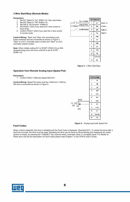
3 Wire Start/Stop (Remote Mode):
Parameters:1. Set DI1 (Start) to “On” (P263=13). See note below.2. Set DI2 (Stop) to “Off” (P264=14).3. Set DI4 to “No function” (P266=0).4. Set P229=1 (DIx) if you want the 3 wire control in
local mode.5. Confirm P230=1 (DIx) if you want the 3 wire control
in remote mode.
Control Wiring: “Start” and “Stop” are momentary pushbutton switches and are connected as shown in Figure 4.“Start” is a N.O. (normally open) contact and “Stop” is a N.C.(normally closed) contact.
Note: When initially setting DI1 to START (P263=13) an E24(programming) error will occur until DI2 is set to STOP(P264=14).
Figure 4 - 3 Wire Start/Stop
Operation from Remote Analog Input (Speed Pot):
Parameters:1. Confirm P222=1 (Remote Speed Ref=AI1)
Control Wiring: Speed Pot value must be ≥ 5KΩ but ≤ 10KΩ at2W and is connected as shown in Figure 5.
Figure 5 – Analog Input with Speed Pot
Fault Codes:
When a fault is detected, the drive is disabled and the Fault Code is displayed. (Example E01). To restart the drive after afault has occurred, the drive must be reset. Resetting the drive can be done by disconnecting and reapplying AC power(power-on reset), by pressing the “O/RESET” key (manual reset), automatic reset, or via digital inputs. For details onReset and a full list and description of Fault Codes please read Chapter 7 in the CFW10 User’s Guide.

6
Pub
licat
ion
Num
er Q
S00
5CF
W10
6
Parameters Example:
• The following is a typical list of parameter changes that may be needed in addition to the factory default settings(P204=5).
P000=5 Parameter Access (5 = Password)P204=5 Loads Factory DefaultP100=5 Acceleration Time = 5 secondsP101=10 Deceleration Time = 10 secondsP133=3.00 Minimum Frequency = 3.00 HzP134=60.00 Maximum Frequency – 60.00 Hz
• Local/Remote parameters allow the drive to be set up to operate from Keypad, Remote Terminal, or aprogrammed combination of keypad and terminal inputs.
P221 – Local Speed Reference SelectionP222 – Remote Speed Reference SelectionP229 – Local Command SelectionP230 – Remote Command SelectionP231 – Forward/Reverse Selection
• Read Only Parameters (P002 – P040) can be used for monitoring and troubleshooting. For a full list anddescription please read the CFW10 User’s Guide. By monitoring certain read only parameters, drive operationalvalues can be determined without the use of any other test equipment.
P002 – Frequency Proportional Value (Speed)P003 – Motor CurrentP004 – used to monitor DC Link Voltage.P005 – Motor FrequencyP007 – Motor Output VoltageP014 – Last fault
These are just a few examples of drive set-up and parameters. Please read the CFW10 User’s Guide for additionalinformation.