Embed Size (px)
Citation preview

Ocean Engineering 195 (2020) 106687
Available online 17 November 20190029-8018/© 2019 Elsevier Ltd. All rights reserved.
CFD investigations of evolution and propulsion of low speed vortex ring
Xiaosong Zhang, Jianhua Wang, Decheng Wan *
School of Naval Architecture, Ocean and Civil Engineering, State Key Laboratory of Ocean Engineering, Shanghai Jiao Tong University, Collaborative Innovation Center for Advanced Ship and Deep-Sea Exploration, Shanghai, 200240, China
A R T I C L E I N F O
Keywords: Vortex ring thruster Evolution of vortex ring Propulsion efficiency OpenFOAM
A B S T R A C T
Vortex ring thruster (VRT) is a new type of propulsion device which adopts impulse propulsion mode. The idea of impulse propulsion comes from bionics. It imitates cephalopods like squid and can achieve high efficiency. Vortex ring is a typical phenomenon during the pulse process and it can help improve the propulsion efficiency. Many previous studies believe that VRT can obtain large thrust and efficiency but few articles study the efficiency problem systematically. In addition, experiment is the main research method adopted at present. In this paper, an axisymmetric piston-nozzle computational model is established to simulate the thruster. Fluid is solved by CFD method based on the open source platform OpenFOAM. Dynamic mesh technology is adopted to control piston motion. This paper focus on two aspects: vortex ring evolution and propulsion efficiency characteristics. In the first part, simulations of pulse process with different strokes are carried out and compared with standard ex-periments. The two results are in good agreement. The vortex ring evolution is then studied with different background flows. In the second part, a reasonable open-water characteristics calculation method for VRT is proposed. Thrust coefficient and propulsion efficiency are obtained in the calculation. The results indicate that the VRT can achieve high efficiency near to 1 in the case of high advance ratio. In addition, efficiency comparison is carried out between four kinds of asymmetric velocity programs and three kinds of symmetric velocity pro-grams to find out a more reasonable velocity program design. Finally, the impact of piston stroke is investigated. Results show that smaller stroke can obtain larger efficiency because pulsation effect is more prominent.
1. Introduction
Propeller is the most common propulsion device for the existing underwater vehicles because of stability and convenience. However, propeller propulsion can cause some inherent energy loss. Propeller generates thrust depending on the rotation of the blades. Swirl velocity of water is generated because of the spin of the blades. Water kinetic energy due to the swirl of water does not contribute to the generation of thrust and therefore it is an energy waste. Previous studies (Van Ter-wisga, 2013) have shown that this rotational kinetic energy losses can be as high as nearly 20%. These energy losses are unavoidable for propeller no matter how optimized. Thus, it is very essential to adopt a new kind of propulsion without rotational energy loss. The impulse propulsion was developed against this background. The idea of impulse propulsion comes from bionics. As a result of natural selection, fast moving marine animals like squid choose impulse mode to swim. This propulsion mode can be simplified to a system consisting of a piston and a nozzle. In this system, the thrust is produced by the piston pushing water. Because the
piston surface always maintains normal to the flow or the thrust axis during the stroke, this propulsion system has no rotational energy loss and can achieve relatively high efficiency. At the same time, the pulse process is often accompanied by the generation of the vortex ring. The vortex ring had been proved that plays an important role in the pro-pulsion. And because of its remarkable effect, the impulse propulsion device is called Vortex-Ring-Thruster (VRT). Based on the above two contents, many scholars have carried out investigation in the past several years (New and Yu, 2015).
Vortex ring is a typical phenomenon in pulse process. A great number of experimental works have been carried out to study vortex ring in the starting flow generated from a piston-nozzle apparatus. Gharib et al. (1998) carried out experimental studies about the formation process of the vortex ring. A piston-nozzle apparatus was used in their experiment to investigate the formation process of vortex rings for a wide range of piston stroke to cylinder diameter (Lm/D) ratio. Several important conclusions were obtained in their studies, which become key basis for follow-up researches. For cases Lm/D < 4, the leading vortex ring is
* Corresponding author. E-mail address: [email protected] (D. Wan).
Contents lists available at ScienceDirect
Ocean Engineering
journal homepage: www.elsevier.com/locate/oceaneng
https://doi.org/10.1016/j.oceaneng.2019.106687 Received 16 May 2019; Received in revised form 15 September 2019; Accepted 3 November 2019

Ocean Engineering 195 (2020) 106687
2
small and there is no trailing vorticity behind the vortex ring. For cases Lm/D � 4, it appears that the leading vortex ring is nearly saturated. For cases Lm/D > 4, there is an obvious trailing vorticity behind the leading vortex ring. Thus, a non-dimensional time called the “Formation time” is defined equals to 4 in their experiment. At the same time, Rosenfeld et al. (1998) carried out CFD simulation to investigate the same problem as Gharib et al. (1998). They found that for the cases Lm/D > 4, the leading vortex ring moves faster and would break off from the trailing vorticity behind, this phenomenon is called “pinch-off”. It is worth noting that their studies were carried out without background flow. Krueger et al. (2003) used similar test equipment as Gharib et al. (1998) to investigate the vortex ring pinch-off in the presence of simultaneously initiated uniform background co-flow. According to their conclusion, the “Formation time” is significantly reduced with the effect of back-ground velocity. Different from Krueger et al. (2003), Jiang and Gro-senbaugh (2006) set a fully developed background co-flow and wake of the nozzle was also present. The strong interaction between the vortex ring and the nozzle wake was studied in their research. On the other hand, many studies have analyzed the mechanism how vortex ring im-proves propulsive thrust. Krueger (2001) used a piston-cylinder mech-anism attached to a force balance to investigate the impulse and thrust generated by starting jets. Krueger and Gharib, (2003, 2005) analyzed the interaction between the vortex ring and the surrounding fluid in detail. As the vortex ring moves forward, it draw in the surrounding fluid, which accelerates the otherwise static fluid to the average velocity of the vortex ring motion. Thus, the momentum of the vortex ring be-comes larger because of the entrained fluid. According to the Newton’s third law, the force of the fluid against the thruster increases. It was also observed in their experiment that the total thrust generated per pulse is much more than that due to momentum flux from the jet alone. The difference is largely due to the over-pressure effect at the nozzle exit during vortex ring formation. Dabiri and Gharib (2004) carried out detailed study focusing on the fluid entrainment by isolated vortex rings. Cater et al. (2004) studied the interaction between piston vortex and primary leading vortex ring in detail in their experiments. The influence of piston vortex on the primary vortex ring was small when the piston was far away from the nozzle exit. However, when the piston vortex was ejected into the flow, it increased the circulation and fluctuation of primary vortex ring. Lim et al. (2001, 2006) and New et al., (2003, 2006) carried out very detailed experimental studies on the evolution and influencing factors of vortex rings in cross flow. Because of the complex interaction between the jet and the cross flow, four kinds of vortex structures were formed. They are the leading-edge vortex, the horseshoe vortex, the wake vortex and the counter-rotating vortex pair. The effects of jet exit shape and velocity profile on the vortex ring evolution were analyzed in detail. More recently, Cheng et al. (2009, 2010, 2016) adopted Lattice Boltzmann Method to simulate vortex ring. The simulation results were proved to be reliable. Besides, the influence of shear flow and the complex evolution process of elliptic vortex rings with different aspect ratios are analyzed.
Based on the researches introduced above, it is generally accepted that pulse propulsion can get a really high efficiency because there is no rotational energy loss and vortex rings can manipulate the over-pressure at the nozzle exit and entrain fluid. Thus, many studies were carried out using the Vortex Ring Thrust (VRT) as propulsion device to investigate the thrust performance. Kamran Mohseni (2006) designed a pulsatile vortex generator for low-speed maneuvering of small underwater vehi-cles. By combining the device and the main propeller, the performance of the underwater vehicle was improved. Krieg and Mohseni (2008) studied the thrust characterization of vortex ring thruster by open-water experiment. The results show that thrust increases with frequency and stroke. Then, Krieg and Mohseni, 2010 designed the dynamic control system for this vortex ring thruster and the corresponding underwater vehicle. Based on the system, the vehicle achieved three different ma-neuver regimes, including Cruising, Docking, and Transition regimes. For the investigation of propulsive efficiency, Moslemi and Krueger
(2010) studied experimentally on a self-propelled, pulsed-jet underwa-ter vehicle. Propulsive efficiency in their study is generally defined as the ratio of the useful propulsive power output to the total power exerted propelling the vehicle, which is given by:
ηp¼Wu
Wu þ Eex�
FT Uv
FT Uv þ Eex(1)
where Uv is the average vehicle velocity, and both FT and Eex can be obtained from the DPIV measurement. Ruiz et al. (2011) designed a self-propelled underwater vehicle with the capability to operate using either steady-jet propulsion or a pulsed-jet mode that features the roll-up of large-scale vortex rings in the near-wake. In their study, a drag-based hydrodynamic efficiency for the vehicle is defined as:
ηh¼FDUSUB
FDUSUB þ 0:5ρAoutUwðUw � U∞Þ2 (2)
By this calculation method, the experiments demonstrate an obvious increment in propulsive efficiency, over 50% greater than the efficiency of the steady-jet mode. In addition, there are some new researches about the soft internal structure of the vortex ring thruster system (Serchi et al., 2013; Renda et al., 2015; Serchi and Weymouth, 2017). Their studies proved that soft-bodied vehicles can benefit from exploiting their own body deformation to obtain larger propulsive forces.
Among the past researches about the propulsive efficiency of the vortex ring thruster, the experimental study of underwater vehicle model is the most common method. Few articles use CFD method to study the efficiency problem systematically. And the efficiency calcu-lation methods are generally defined for whole vehicle in experiment. In this paper, the authors use CFD method to study open-water perfor-mance of the vortex ring thruster. Firstly, the basic vortex ring evolution is simulated using the same geometry and condition with Gharib et al. (1998) and Jiang and Grosenbaugh (2006) for comparison. Then, the impact of background flow on the vortex ring evolution is investigated. For the thrust and efficiency study, the authors propose an open water characteristic calculation method. Detailed analysis is carried out about the force on piston, the thrust and the efficiency with different piston velocity program, nozzle length and piston stroke.
2. Numerical design
2.1. Computational domain
In this paper, a piston-nozzle apparatus is established to simulate the thruster. Only the thruster model is built in order to perform an open- water simulation. The whole computational domain is axisymmetric, consisting of a piston-nozzle apparatus and outer flow domain. The domain configuration is shown in Fig. 1.
The details of the domain dimension and boundary conditions are shown in Fig. 2. Dimensions of the piston and nozzle are exactly the same as previous experiments of Gharib et al. (1998). The inner diam-eter (D) of nozzle is 0.0254m, and the total length of the nozzle (Lp) is 0.4m which limits the maximum stroke ratio (L/D)max to 15.7. The nozzle exit adopts a sharp-wedged form with a tip angle of 20�. The outer flow domain spans 10D in the streamwise direction and 2.5D in the radial direction. The piston surface is a motion boundary. Moving
Fig. 1. Computational domain configuration.
X. Zhang et al.

Ocean Engineering 195 (2020) 106687
3
velocity Up in x-direction is imposed on the boundary throughout the whole pulse pushing process in the simulation. The average of Up is equal to 0.1524 m/s for all cases. No-slip boundary condition is adopted in the inner surface of nozzle so that the vortex ring can be generated by the shear layer. The side boundary of the outer domain uses slip boundary condition. The left patch of the outer flow domain is a wall boundary for the conditions without background flow and an inlet boundary with a velocity Us for cases with background flow.
In order to better describe the calculation conditions and results in the following simulations, two non-dimensional times are defined as:
T*¼Lm
D¼
UpTD
(3)
t*¼LD¼
UptD
(4)
where Lm is piston stroke, L is the distance of piston motion, D is the inner diameter of nozzle. Up is piston velocity. Thus, T* represents the total moving time of the piston and t* represent the time piston is moving.
2.2. Governing equations and numerical scheme
A relatively low piston velocity is adopted in the present study. Referring to previous numerical simulation studies using the same speed conditions (Jiang and Grosenbaugh, 2006), an unsteady, laminar, incompressible, and Newtonian flow is assumed. The time-dependent incompressible Navier-Stokes equations are employed for solving the flow. The governing equations can be written as follows:
rui ¼ 0 (5)
∂ui
∂tþðui ⋅rÞui ¼ � rpþ υr2ui (6)
where ui is velocity in three directions (i ¼ x, y, z), r is divergence operator, r2 is Laplace operator, and ν is the fluid kinematic viscosity. For the incompressible flow, the fluid density ρ is 1.0 � 103 kg/m3, fluid kinematic viscosity ν is 1.0 � 10� 6 m2/s.
In the present work, the governing equations with the above- described computational domain and simulation conditions are solved based on open-source platform OpenFOAM. The solver pimpleDyMFoam is used to solve the impulse problem. In this solver, the PIMPLE method which is the combination of SIMPLE and PISO is used to handle pressure- velocity coupling. Temporal discretization is a second-order implicit scheme, and second-order scheme is used for spatial discretization.
2.3. Dynamic mesh technology
In order to simulate piston-nozzle jet, dynamic mesh technology is used to control the piston motion. The mesh motion is obtained by solving a mesh motion equation, where boundary motion acts as a boundary condition and determines the position of mesh points. The motion is characterized by the spacing between nodes, which changes by stretching and squeezing. The mesh motion equation used in this work is a Laplace equation with variable diffusivity, which can be written as follows:
r ⋅�γrug
�¼ 0 (7)
where the ug is the velocity of mesh motion. By this velocity, the mesh moves forward to a new position:
Xnew¼Xold þ ugΔt (8)
The coefficient γ in Eqn. (7) is the diffusion coefficient, which is given by diffusivity. Diffusivity model is used to determine how the points should be moved after solving the cell motion equation for each time step. In this work, the diffusivity model is:
γðrÞ¼1rm (9)
where r is the radius from the moving boundary, m is an integer. In this study, for x direction, m is set to 1 to obtain an appropriate mesh motion, for y direction and z direction, m is set to a very large number so that the mesh motion in these two directions are restrained.
The schematic diagram of mesh motion can be seen in Fig. 3.
2.4. Grid distribution and sensitivity study
Fig. 4 shows the detailed grid distribution. Structured grids are adopted in the whole computational domain. Grids in the nozzle are uniform in three directions while grids in the outer flow domain are equal-ratio distribution in the radial direction. In order to reduce nu-merical dissipation, the aspect ratio of the grids near the evolution path of the vortex ring is equal to 1.
According to previous literatures, it is essential to accurately calcu-late the friction in the nozzle to simulate the formation of vortex accu-rately. The nozzle domain is separated from the whole computational domain and an internal nozzle flow simulation without piston motion is carried out. The frictional resistance of inner wall of the nozzle under different grids is calculated. By doing this, the grids distribution 80 � 50 � 40 is adopted for the nozzle domain. For the outer flow domain, pressure of specific point was applied for grid sensitivity study. It avoids the problem in the previous numerical researches’ grid sensi-tivity study (Rosenfeld et al., 1998; Jiang and Grosenbaugh, 2006) that total circulation cannot reflect the particulars. The specific point is on the central axis of the nozzle and 2D distance away from the nozzle exit. Test results are shown as Fig. 5.
According to the results of grid sensitivity study, 1000 � 60 � 40 grids in the axial, radial and circumferential directions is good enough. At the same time, by adopting this grid distribution, aspect ratio of the grids near the vortex evolution path is about 1. This grid distribution is used in all the following simulations.
3. Vortex ring evolution
Vortex ring evolution is a typical phenomenon in pulse process. In order to validate the numerical method used in this paper, standard vortex ring evolution without background flow is simulated and compared with the standard measurement results. In addition, consid-ering the steady sailing state of a vehicle equipped with the vortex ring thruster, the speed of the vehicle can be converted into a background flow. The influence of background flow on vortex ring evolution is
Fig. 2. Domain dimension and boundary conditions.
X. Zhang et al.

Ocean Engineering 195 (2020) 106687
4
simulated and discussed.
3.1. Inexistence of background flow
First simulations are the pulse process in different strokes without background flow. These standard cases are performed in the same
condition as the standard experiments of Gharib et al. (1998) and nu-merical simulation of Rosenfeld et al. (1998).
Fig. 6 presents the comparison of instantaneous vorticity field for the three different piston strokes (T* ¼ 2, T* ¼ 3.8, T* ¼ 14.5) between numerical results and experimental results. It is obvious that the CFD results are in good agreement with the experimental results regarding to
Fig. 3. Nozzle mesh deformation at three different times.
Fig. 4. Grid distribution.
Fig. 5. Grid sensitivity study in axial and radial direction.
X. Zhang et al.

Ocean Engineering 195 (2020) 106687
5
the vortex ring formation. The vortex ring keeps getting bigger before T* up to 4 and reaches saturation finally when T* is approximately equal to 4. Trailing vorticity appears when T* is larger than 4. The evolution of leading vortex ring is simulated well. Smaller vortex can be captured in the case of large T*.
The changes of total circulation and vortex ring circulation can reflect the evolution of vortex in pulse jet. Fig. 7 presents the non- dimensional circulation change with the non-dimensional time t* for stroke ratio T* ¼ 6. Total circulation and vortex circulation are defined as the velocity circulation on the closed curve formed by the boundary of
outer flow domain and the leading vortex ring outline, respectively. Velocity circulation was calculated according to the Stokes theorem, which indicates that curl of velocity is the surface density of the circu-lation. The expression can be written as: I
lU! ⋅ d l
!¼
Z
Sr� U!⋅d S! (10)
In Fig. 7, total circulation increases linearly during the pushing stroke, and then decreases slowly after the piston stop. All the three results are in good agreement. The horizontal black line represents the maximum value of vortex circulation, the intersection of the horizontal line and the total circulation curve represents the formation number. Under this flow condition, the formation number should be approxi-mately equal to 4. As the figure shows that the CFD calculation correctly predicts the formation number.
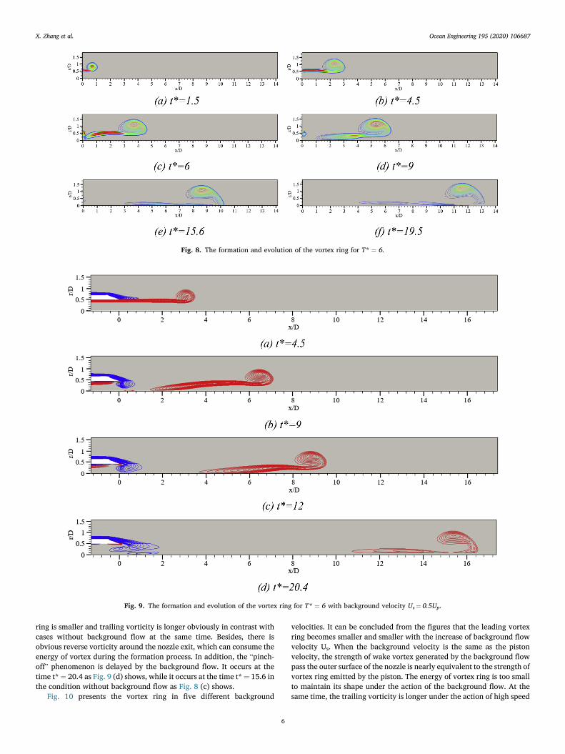
The vorticity field in the formation and evolution phases of vortex ring with T* ¼ 6 is shown in Fig. 8. The leading vortex ring continues to grow up until t* is equal to 6. And there is obvious trailing vorticity behind the leading vortex ring. After the energy of vortex is saturated, the trailing vorticity cannot get into the vortex, and the trailing vorticity becomes longer and longer during the evolution. The large-scale leading vortex contains larger energy and moves faster, then the “pinch-off” phenomenon occurs at t* ¼ 15.6 (e). The vortex ring disconnects itself from the bulk of the flow, leaving behind a noticeable tail of vorticity flow region.
3.2. Existing background flow
Under the steady sailing state of the vehicle, the thruster has a certain advance speed. Thus, it is necessary to place this apparatus into an environment with background flow to investigate vortex ring evolution in the presence of background velocity.
The influence of background flow on vortex ring can be seen from Fig. 9. The background velocity is set to be half of the piston velocity. Vorticity is colored by rotation directions of vortex. Firstly, the vortex
Fig. 6. Comparison of vortex ring between CFD results in this work and experimental results by Gharib et al.
Fig. 7. Comparison of circulation between CFD results in this work, CFD results of Rosenfeld and experimental results by Gharib et al.
X. Zhang et al.
Ocean Engineering 195 (2020) 106687
6
ring is smaller and trailing vorticity is longer obviously in contrast with cases without background flow at the same time. Besides, there is obvious reverse vorticity around the nozzle exit, which can consume the energy of vortex during the formation process. In addition, the “pinch- off” phenomenon is delayed by the background flow. It occurs at the time t* ¼ 20.4 as Fig. 9 (d) shows, while it occurs at the time t* ¼ 15.6 in the condition without background flow as Fig. 8 (c) shows.
Fig. 10 presents the vortex ring in five different background
velocities. It can be concluded from the figures that the leading vortex ring becomes smaller and smaller with the increase of background flow velocity Us. When the background velocity is the same as the piston velocity, the strength of wake vortex generated by the background flow pass the outer surface of the nozzle is nearly equivalent to the strength of vortex ring emitted by the piston. The energy of vortex ring is too small to maintain its shape under the action of the background flow. At the same time, the trailing vorticity is longer under the action of high speed
Fig. 8. The formation and evolution of the vortex ring for T* ¼ 6.
Fig. 9. The formation and evolution of the vortex ring for T* ¼ 6 with background velocity Us ¼ 0.5Up.
X. Zhang et al.

Ocean Engineering 195 (2020) 106687
7
background flow. The reason for vortex morphological change can be analyzed by the changes of circulation under different background flows. Fig. 11 shows the non-dimensional circulation as a function of formation time for Us ¼ 0.25Up and Us ¼ 0.75Up cases. The calculated total circulation in Fig. 11 only includes the vortex produced by the piston motion, in other words, the red vorticity in Fig. 10. There are two reasons why the vortex rings become smaller at high background ve-locity. Firstly, the increasing Us decreases the strength of the shear layer feeding the ring. The reverse vortex produced by background flow consume the energy of vortex ring and trailing vorticity. It can be seen from Fig. 11 that both total circulation and vortex circulation decrease as the background velocity increases. Secondly, the increasing Us in-creases the velocity that the ring moves away from the nozzle. As mentioned in section 3.1, the formation number represents the non-
dimensional time that the jet shear layer rolls up to form the vortex ring. The dotted line in Fig. 11 shows that the formation number is about 3 and 1 for case with Us ¼ 0.25Up and case with Us ¼ 0.75Up, respec-tively. After the formation time, the leading vortex ring will stop entraining circulation and the remainder of the jet will be ejected into the trailing vorticity. With the increase of background velocity, the time of vortex ring entraining circulation becomes shorter, which leads to the smaller vortex ring.
4. Thrust and efficiency characteristics
In this section, the thrust and efficiency characteristics of the vortex ring thruster is discussed. In past studies, the research methods of open water characteristics are not clear. In this paper, the open water
Fig. 10. Vortex ring in different background velocity for T* ¼ 6. Figures are taken at t* ¼ 6.6.
X. Zhang et al.

Ocean Engineering 195 (2020) 106687
8
characteristic parameters and calculation methods are proposed at first. The thrust and efficiency of the thruster are given quantitatively under an actual piston velocity program and an appropriate nozzle length. On the basis, the impact of piston velocity program and stroke on efficiency are discussed.
4.1. Parameters definition
In past studies, there is no standard open-water characteristic defi-nition for vortex ring thruster. In this paper, an open water characteristic calculation method similar to propeller is proposed. The calculated pa-rameters include advance ratio, thrust coefficient and open-water effi-ciency. The advance ratio J and thrust coefficient KT are defined as:
J¼Us
Up(11)
KT ¼T
ρApUp2 (12)
where Up is the piston velocity, Us is the ambient velocity. In other words, Us is the advance velocity of the thruster. Ap is the sectional area of the nozzle. The thrust T can be calculated based on the instantaneous axial velocity and pressure at the nozzle exit as:
T ¼ ρZ
u2xdSþ
Z
ðp � p∞ÞdS (13)
where ux is the x direction velocity of the piston exit-surface, p is the pressure of the piston exit-surface, S is the area of the piston exit-surface, p∞ ¼ 0 is the ambient pressure. The two terms on the right side represent two kinds of contributions to the thrust. The first term is the momentum flux term, while the second term is the pressure term.
Propulsive efficiency is defined as the work done by the thrust divided by the total work done by the piston, which can be written as:
η0¼UsR T*
0 TdtR T*
0
�Fp� flowUp þ Fp� pushUp
�dt
(14)
where Fp� flow is the pressure on the surface of the piston caused by the presence of background flow. This pressure is present before the piston moves. The piston has to overcome it to do work, even though it is small in magnitude. Fp� push is the pressure of water on the piston as it pushes water forward.
4.2. Open-water characteristics calculation
In this section, cases are performed in five different advance ratios J ¼ 0, 0.25, 0.5, 0.75, 1. The change of advance ratio is depended on the change of ambient velocity Us, the average piston velocity is uniform Up ¼ 0.1524 m/s. Stroke ratios of these cases are T* ¼ 6.
Firstly, a fully pulsed velocity program as function (15) is used to control the piston motion, the velocity program is shown in Fig. 12. “Fully Pulsed” means that the piston complete acceleration and decel-eration in a flash. This velocity curve is the same as that used in previous numerical studies of Jiang and Grosenbaugh (2006). t* ¼ 0 in this figure stands for the moment that piston starts moving.
U¼
8<
:
0t* ¼ 0Up0 < t* < T*
0t ¼ T*(15)
Fig. 13 presents an example of the calculated force on piston and thrust for the case of T* ¼ 6, J ¼ 0.5. At the beginning, the piston is stationary for t* ¼ 0–1.8. After the forces are stable, the piston starts to move. For the force on the piston (a), when the piston starts moving, the fluid in the nozzle is accelerated to the velocity Up instantaneously because the fluid is incompressible, the piston is subjected to a great impact force. As the piston moves forward, fluid in the nozzle decreases, and the total frictional force of fluid and nozzle inner wall decreases, so force on the piston decreases gradually. The piston face receives a pos-itive force due to the inertia of the fluid in the nozzle when the piston stops. For the thrust, the total thrust is divided into two parts: thrust from momentum and thrust from pressure. In the process of piston moving, the contribution of momentum is the main component, thrust from pressure is very small in contrast with thrust from momentum. Thrust from momentum is attenuating to zero rapidly when the piston stops, while thrust from pressure mutants to a positive value. These phenomena indicate that thrust from pressure cannot be ignored for impulse jet propulsion. This part of the thrust will contribute to the continuous thrust process.
Fig. 14 presents the open-water performance curves for T* ¼ 6 with pulse velocity program. It can be seen from the figure that both thrust and efficiency increase with the advance ratio. The efficiency reaches a really high number more than 1 when advance ratio J is close to 1. It seems to be an impossible result. However, Jiang and Grosenbaugh (2006) carried out a similar simulation of pulse propulsion, they calculated the energy ratio defined in their paper, which is a quantity
Fig. 11. Non-dimensional circulation as a function of formation time with two different background velocities.
Fig. 12. Fully pulsed velocity program.
X. Zhang et al.

Ocean Engineering 195 (2020) 106687
9
similar to efficiency but considers the drag. They also got results more than ideal efficiency but unfortunately there is no explanation. In this paper, the authors consider that the reason for this phenomenon is the unreal fully pulsed velocity program which amplifies the effect of the pulse on increasing efficiency. Besides, the impact force of the instant acceleration cannot be obtained accurately. The piston does a lot of work accelerating the fluid in the nozzle. However, in the simulation with fully pulsed velocity program, the acceleration process is completed in a flash, resulting in the force on the piston cannot be accurately calculated correctly. Therefore, a more practical velocity program with accelerating ramp and decelerating ramp is adopted for further investigation. The practical velocity program function is pre-sented by function (16) and the curve is shown in Fig. 15.
UpðtÞ ¼ Umax
h1 � cos
π0:1T*t*
i2Umaxt*=T* 2 ð0:1; 0:9Þ
t*=T* 2 ð0:9; 1Þ
h1 � cos
π0:1T* ðt
* � 0:8T*Þi
(16)
where Umax ¼ Up=ð2 � 0:9Þ. Up equals to 0.1524 m/s to keep the same piston velocity.
Cases are performed in five different advance ratios J ¼ 0, 0.25, 0.5, 0.75, 1. Fig. 16 presents an example of the calculated force on piston and thrust for the case of T* ¼ 6, J ¼ 0.5.
It can be seen from Fig. 16 that by using the practical velocity pro-gram, the accelerating ramp and decelerating ramp of piston velocity play a significant role in force on piston and thrust. As is shown in the figure (a), the piston does most of its work in the acceleration stage, and
Fig. 13. Non-dimensional forces as functions of the non-dimensional formation time t* for the case of T* ¼ 6, J ¼ 0.5 using fully pulsed velocity program.
Fig. 14. Open-water performance curve: Thrust coefficient KT and open-water efficiency η0 as functions of the advance ratio J for T* ¼ 6 using fully pulsed velocity program.
Fig. 15. Practical velocity program with accelerating ramp and deceler-ating ramp.
X. Zhang et al.

Ocean Engineering 195 (2020) 106687
10
the piston has an effect of energy recovery at the deceleration stage because of the inertia of the fluid still in the nozzle. For figure (b), the thrust is a large positive value in the piston acceleration stage and be-comes negative in the piston deceleration stage. The positive and negative of thrust in this two stages are mainly affected by the pressure at the nozzle exit. Fig. 17 presents the pressure fields near the nozzle exit at typical moments. The fluid is considered incompressible in the calculation, so the acceleration and deceleration of the piston directly cause the fluid in the nozzle to accelerate and decelerate. The acceler-ation of the fluid creates an increase in pressure at the nozzle exit, and conversely, the deceleration of the fluid creates a pressure drop at the nozzle exit. In the process of pushing the piston forward at a certain speed (0.1 < t*/T*<0.9), thrust from pressure is very small in contrast with thrust from momentum.
The open-water performance curves for T* ¼ 6 with practical ve-locity program are shown in Fig. 18. In contrast with the cases using fully pulsed velocity program, the efficiency value is kept within a reasonable range. The rationality of the calculation method is proved.
It is worth noting that the total length of the nozzle is fixed at 0.4m (T* ¼ 15.7) at present, which is based on previous literatures. However, a practical thruster would not use such a long stroke, the results intro-duced above are all based on T* ¼ 6. The excess nozzle length causes an
unnecessary loss of energy due to the viscosity. Therefore, it is essential to adjust the total length of nozzle to be equal to the stroke.
In the next simulation, the total nozzle length is set to be approxi-mately equal to the piston stroke, which is more practical. Specifically, for T* ¼ 6, the total length of nozzle is 0.16m. Initial and final nozzle length for T* ¼ 6 are shown in Fig. 19. Cases are performed in five different advance ratios J ¼ 0, 0.25, 0.5, 0.75, 1.
Fig. 20 and Fig. 21 present the results using short nozzle. Contrasting Fig. 21 with Fig. 18, the thrust coefficients are almost identical, but the open-water efficiency with short nozzle length is much higher than that with long nozzle. The reason is that the piston does less work with the shorter nozzle. The instantaneous vorticity fields of cases with different total length of nozzle are shown in Fig. 22. The shape and size of vortex rings are basically the same in the two cases. The vortex ring only affect the thrust, so the coefficients in the two cases remain basically un-changed. In the case with short nozzle length, the piston is very close to the nozzle exit when it stops moving. While in the case with long nozzle length, the piston is still a long way (� 9<x/D < 0) from the nozzle exit when it stops moving. It can be seen from Fig. 22 that there is significant friction between the fluid and the internal wall in this excess length, which increase the work done by piston and reduce the efficiency of thruster. The vortex ring thruster is proved that can achieve high
Fig. 16. Non-dimensional forces as functions of the non-dimensional formation time t* for the case of T* ¼ 6, J ¼ 0.5 using practical velocity program.
Fig. 17. Pressure fields near the nozzle exit at typical moments in the acceleration stage and deceleration stage.
X. Zhang et al.

Ocean Engineering 195 (2020) 106687
11
efficiency in the case of large advance ratio according to Fig. 21. Small underwater vehicle will maintain a high advance coefficient during the voyage. Therefore, the use of this thruster will greatly improve the efficiency.
At the same time, the curve of force on the piston with short nozzle is
different from that with long nozzle. In Fig. 20 (a), the piston can recover energy from the fluid still in the nozzle due to the inertia at the decel-eration stage. In the present condition with short nozzle, there is little fluid left in the nozzle at the end of stroke. The recover energy is extremely small in contrast with the energy consuming in the acceler-ation stage, which leads to the average force acting on the piston in-creases, and the efficiency decreases. This phenomenon indicates that the velocity program of the piston has an effect on the work done by the piston at the same average velocity. Thus, it is essential to try some different kinds of piston velocity program and check the efficiency changes.
4.3. Effect of velocity program on efficiency
Firstly, the authors adopt five kinds of velocity programs as Fig. 23 to investigate the impact of asymmetric acceleration stage and decelera-tion stage on the efficiency. The phrase “Velocity Program” is abbrevi-ated as VP in the follow figures. Velocity program VP1 consists of 10% acceleration stage and 90% deceleration stage, VP2 consists of 30% acceleration stage and 70% deceleration stage. VP4 and VP5 are just
Fig. 18. Open-water performance curve: Thrust coefficient KT and open-water efficiency η0 as functions of the advance ratio J for T* ¼ 6 using practical ve-locity program.
Fig. 19. Initial and final nozzle length for T* ¼ 6.
Fig. 20. Non-dimensional forces as functions of the non-dimensional formation time t* for the case of T* ¼ 6, J ¼ 0.5 with short nozzle.
Fig. 21. Open-water performance curve: Thrust coefficient KT and open-water efficiency η0 as functions of the advance ratio J for T* ¼ 6 with short nozzle.
X. Zhang et al.

Ocean Engineering 195 (2020) 106687
12
contrary to VP1 and VP2. These five velocity programs have the same average velocity Up ¼ 0.1524 m/s. Stroke ratios of these cases are T* ¼6. Two kinds of advance ratio J ¼ 0.75 and J ¼ 1 are calculated.
The efficiency with five different velocity programs is shown in Fig. 24. The presented results are in two kinds of advance ratio J ¼ 0.75 and J ¼ 1. The figure shows that case with velocity program VP5 can obtain the best efficiency, which is about 2% larger than that with VP1. In order word, adopting a velocity program with a slow acceleration stage and a faster deceleration stage can improve the propulsion effi-ciency under the same average piston velocity.
The reasons for the difference in efficiency are analyzed from the perspective of piston force and thrust. Fig. 25 presents the piston force and total thrust comparison between results from VP1 and VP5. The effect of the length of the acceleration and deceleration stages on the performance can be seen from these figures. In the figure (a), piston with velocity program VP1 does a lot of work in the acceleration stage because that it has to accelerate the fluid in the nozzle with great ac-celeration. In the deceleration stage, the recover energy of piston with VP1 is small because the acceleration is small. VP1 is the velocity pro-gram with the most work done by the piston in the five velocity pro-grams. On the other hand, piston with VP5 does less work in the acceleration stage and has more energy recovery in the deceleration stage. It is the velocity program with the least work done by the piston in
the five velocity programs. In the figure (b), total thrust with VP1 suddenly increases in the
acceleration stage. This increase is from the pressure contribution to the thrust due to the large acceleration. In the deceleration stage, there is no negative thrust value because the deceleration process is relatively slow. On the contrary, total thrust with VP5 has no thrust increase and there are negative values in the deceleration. In conclusion, using velocity program VP1 can obtain the largest thrust, on the contrary, the thrust obtained by using velocity program VP5 is the smallest.
In addition, the efficiency comparison with three symmetrical ve-locity programs is carried out. The piston velocity programs are shown in Fig. 26. The velocity program VP3 is the same as Fig. 23. The accel-eration stage and deceleration stage accounts for 60% of the VP6 and 20% of the VP7. These three velocity programs have the same average velocity Up ¼ 0.1524 m/s. Stroke ratios of these cases are T* ¼ 6.
The efficiency comparison results are shown in Fig. 27. The results indicate that the case with velocity program VP7 has the highest effi-ciency, while the case with VP3 have the lowest efficiency. Combined with the velocity program curves in Fig. 26, it can be found that the acceleration stage and deceleration stage of velocity program VP7 are the most rapid. Therefore the case with velocity program VP7 has the most obvious pulse effect, which contribute to improve the efficiency.
Fig. 22. Vorticity fields of cases with different total length of nozzle. Figures are taken at t* ¼ 1T*.
Fig. 23. Five kinds of velocity programs. Fig. 24. Efficiency comparison with five different asymmetric veloc-ity programs.
X. Zhang et al.

Ocean Engineering 195 (2020) 106687
13
In addition, the comparison of vortex ring morphology between case with velocity program VP3 and VP7 is shown in Fig. 28. In the case with VP3, the piston accelerates relatively slowly, which leads to the slow formation and small size of vortex ring. In contrast, the vortex ring with VP7 suck up more energy and becomes larger and faster, which is beneficial to efficiency improvement. In conclusion, in order to obtain higher propulsion efficiency, the velocity program with more rapid ac-celeration and deceleration stage should be adopted.
4.4. Effect of piston stroke on efficiency
Piston stroke is another important parameter for the vortex ring thruster. For practical thrusters, it is unlikely to use a long nozzle considering the interior space of the vehicle. The authors choose four kinds of relatively small non-dimensional strokes (T* ¼ 2, T* ¼ 4, T* ¼ 6, T* ¼ 8) to study the relationship between efficiency and stroke. It is worth noting that the total length of the nozzle is set to be approximately equal to the piston stroke for these cases. The computational results are
shown in Fig. 29. The computational results in Fig. 29 indicate that the efficiency de-
creases as the stroke increases. When the piston stroke reduces, the pulse action during propulsion is more significant. Based on the conclusion that the pulse motion can improve the propulsion efficiency, thruster with small stroke has larger efficiency than that with larger stroke.
5. Conclusions
In this paper, CFD method is used to investigate the vortex ring evolution and efficiency characteristics of low speed vortex ring thruster. In the first part, the simulation is validated by comparison with measurement results. The vortex ring evolution process is discussed with and without background flow. In the second part, the authors focus on the open-water characteristics of vortex ring thruster. Detailed analysis is carried out about the force on piston, the thrust and the efficiency with different piston velocity program, nozzle length and piston stroke.
Fig. 25. Non-dimensional forces comparison between results from VP1 and VP5.
Fig. 26. Three kinds of symmetric velocity programs. Fig. 27. Efficiency comparison with three different symmetric veloc-ity programs.
X. Zhang et al.

Ocean Engineering 195 (2020) 106687
14
Conclusions are as follows:
(1) An axisymmetric piston-nozzle computational model is estab-lished to simulate the vortex ring thruster. The vortex ring evo-lution and circulation are in good agreement with previous standard experiments. With the increase of background flow ve-locity, the leading vortex ring is getting smaller and smaller. There are two main reasons for the morphological changes of vortex rings. Firstly, the reverse vortex produced by background flow decreases the strength of the shear layer feeding the ring. Secondly, the increasing Us increases the velocity that the ring moves away from the nozzle, which reduces the time for vortex ring to gather energy. At the same time, the “pinch-off” phe-nomenon is delayed.
(2) The open water characteristic parameters definition and calcu-lation methods of vortex ring thruster are proposed. The thrust and efficiency of the thruster are given quantitatively under an actual piston velocity program and an appropriate nozzle length. The open-water performance curve is obtained by calculation. The vortex ring thruster has been proved that can achieve high efficiency in the case of large advance ratio.
(3) For piston velocity programs with the same average velocity, higher efficiency can be obtained by using velocity program with rapider acceleration and deceleration stages. If an asymmetric velocity program is to be adopted, using a velocity program with a more gradual acceleration process and a sharper deceleration
process can obtain larger efficiency. For the impact of piston stroke, the results indicate that the efficiency decreases as the stroke increases, which because that the pulsation effect is more prominent in the case of small stroke.
The vortex rings are produced intermittently during the actual operation of thruster. Therefore, the frequency plays an important role in the vortex ring evolution and the propulsion performance. The au-thors are currently working to simulate the complex vortex interaction and in a continuous pulsed jet propulsion.
Acknowledgments
This work is supported by the National Natural Science Foundation of China (51879159, 51490675, 11432009, 51579145), Chang Jiang Scholars Program (T2014099), Shanghai Excellent Academic Leaders Program (17XD1402300), Program for Professor of Special Appoint-ment (Eastern Scholar) at Shanghai Institutions of Higher Learning (2013022), Innovative Special Project of Numerical Tank of Ministry of Industry and Information Technology of China (2016-23/09), to which the authors are most grateful.
References
Cater, J.E., Soria, J., Lim, T.T., 2004. The interaction of the piston vortex with a piston- generated vortex ring. J. Fluid Mech. 499, 327–343.
Cheng, M., Lou, J., Lim, T.T., 2009. Motion of a vortex ring in a simple shear flow. Phys. Fluids 21 (8), 081701.
Cheng, M., Lou, J., Lim, T.T., 2010. Vortex ring with swirl: a numerical study. Phys. Fluids 22 (9), 097101.
Cheng, M., Lou, J., Lim, T.T., 2016. Evolution of an elliptic vortex ring in a viscous fluid. Phys. Fluids 28 (3), 037104.
Dabiri, J.O., Gharib, M., 2004. Fluid entrainment by isolated vortex rings. J. Fluid Mech. 511 (511), 311–331.
Gharib, M., Rambod, E., Shariff, K., 1998. A universal time scale for vortex ring formation. J. Fluid Mech. 360, 121–140.
Jiang, H., Grosenbaugh, M.A., 2006. Numerical simulation of vortex ring formation in the presence of background flow with implications for squid propulsion. Theor. Comput. Fluid Dyn. 20 (2), 103–123.
Krieg, M., Mohseni, K., 2008. Thrust characterization of a bioinspired vortex ring thruster for locomotion of underwater robots. IEEE J. Ocean. Eng. 33 (2), 123–132.
Krieg, M., Mohseni, K., 2010. Dynamic modeling and control of biologically inspired vortex ring thrusters for underwater robot locomotion. IEEE Trans. Robot. 26 (3), 542–554.
Krueger, P.S., 2001. The Significance of Vortex Ring Formation and Nozzle Exit Over- pressure to Pulsatile Jet Propulsion. California Institute of Technology Pasadena, California.
Krueger, P.S., Dabiri, J.O., Gharib, M., 2003. Vortex ring pinchoff in the presence of simultaneously initiated uniform background co-flow. Phys. Fluids 15 (7), L49–L52.
Krueger, P.S., Gharib, M., 2003. The significance of vortex ring formation to the impulse and thrust of a starting je. Phys. Fluids 15 (5), 1271–1281.
Krueger, P.S., Gharib, M., 2005. Thrust augmentation and vortex ring evolution in a fully-pulsed jet. AIAA J. 43 (4), 792–801.
Lim, T.T., New, T.H., Luo, S.C., 2001. On the development of large-scale structures of a jet normal to a cross flow. Phys. Fluids 13 (3), 770–788.
Lim, T.T., New, T.H., Luo, S.C., 2006. Scaling of trajectories of elliptic jets in crossflow. AIAA J. 44 (12), 3157–3160.
Mohseni, K., 2006. Pulsatile vortex generators for low-speed maneuvering of small underwater vehicles. Ocean Eng. 33 (16), 2209–2223.
Fig. 28. Vortex ring morphology with different velocity programs at time t* ¼ 0.5T*.
Fig. 29. Efficiency comparison with different piston strokes.
X. Zhang et al.

Ocean Engineering 195 (2020) 106687
15
Moslemi, A.A., Krueger, P.S., 2010. Propulsive efficiency of a biomorphic pulsed-jet underwater vehicle. Bioinspiration Biomim. 5 (3), 036003-14.
New, D.T.H., Yu, S.C.M., 2015. Vortex Rings and Jets. Springer, Singapore. New, T.H., Lim, T.T., Luo, S.C., 2003. Elliptic jets in cross-flow. J. Fluid Mech. 494,
119–140. New, T.H., Lim, T.T., Luo, S.C., 2006. Effects of jet velocity profiles on a round jet in
cross-flow. Exp. Fluid 40 (6), 859–875. Renda, F., Giorgioserchi, F., Boyer, F., et al., 2015. Locomotion and Elastodynamics
Model of an Underwater Shell-like Soft Robot, pp. 1158–1165, 2015. Rosenfeld, M., Rambod, E., Gharib, M., 1998. Circulation and formation number of
laminar vortex rings. J. Fluid Mech. 376, 297–318.
Ruiz, L.A., Whittlesey, R.W., Dabiri, J.O., 2011. Vortex-enhanced propulsion. J. Fluid Mech. 668 (4), 5–32.
Serchi, F.G., Arienti, A., Laschi, C., 2013. Biomimetic vortex propulsion: toward the new paradigm of soft unmanned underwater vehicles. IEEE ASME Trans. Mechatron. 18 (2), 484–493.
Serchi, F.G., Weymouth, G.D., 2017. Underwater soft robotics, the benefit of body-shape variations in aquatic propulsion. In: Guglielmelli, E. (Ed.), Soft Robotics Week 2016: Trends, Applications and Challenges of Soft Robots, 17. Springer, Cham.
Van Terwisga, T., 2013. On the working principles of energy saving devices. World Wastes.
X. Zhang et al.