Embed Size (px)
Citation preview

Page 1 of 39
Cervélo P5 Technical White Paper By Damon Rinard, Senior Advanced R&D Engineer & Phil White, Co-Founder
Contents Aerodynamic heritage .......................................................................................................................................... 3
P5 Frameset: Faster .............................................................................................................................................. 4
Previous development process .................................................................................................................... 4 The P5 development process ....................................................................................................................... 4
Wind tunnel test results ................................................................................................................................... 7 How much power can the P5 save? ............................................................................................................. 9 How much time can the P5 save? ................................................................................................................ 9
P5 Aero Design Elements ................................................................................................................................. 9 TrueAeroTM library ........................................................................................................................................ 9 Aero zone design ........................................................................................................................................ 10 Head tube aero zone .................................................................................................................................. 10 Seat tube aero zone ................................................................................................................................... 11 Hidden Pocket ............................................................................................................................................ 13 Fork chord options ..................................................................................................................................... 14
Stiffness .......................................................................................................................................................... 15 Light weight .................................................................................................................................................... 14
P5 Frameset Features ......................................................................................................................................... 15
Wide fit range ................................................................................................................................................. 16 ComfortPlyTM technology ............................................................................................................................... 16 Low friction Internal Cable Stops (ICS3) ......................................................................................................... 16 Fork accepts all brakes ................................................................................................................................... 17 All-tires cutout ................................................................................................................................................ 17 Fits all wheels ................................................................................................................................................. 18 Fork compatibility........................................................................................................................................... 18
Aero bar .............................................................................................................................................................. 18
Adjustability: fit = fast .................................................................................................................................... 19 Arm pad stack adjustment ......................................................................................................................... 19 Arm pad reach adjustment ........................................................................................................................ 20 Arm pad lateral adjustment ....................................................................................................................... 21 Arm pad rotational adjustment ................................................................................................................. 21 Extension adjustment ................................................................................................................................ 21 Base bar stack and reach ............................................................................................................................ 21
Simple: Fewer parts ........................................................................................................................................ 21 Frame + bar = aero fit ..................................................................................................................................... 22
Aerodynamics: Faster ......................................................................................................................................... 23
Skin surfaces: Cervélo engineered ................................................................................................................. 24 Aero-matched with frame and brake ............................................................................................................. 25 100% hidden cables ........................................................................................................................................ 26 Compatible with both brake cable styles ....................................................................................................... 26 Fully integrated for Di2................................................................................................................................... 27
Page 2 of 39
Brakes: Aerodynamics by Cervélo, hydraulics by Magura ................................................................................. 27
Brake development: caliper ........................................................................................................................... 27 Brake development: lever .............................................................................................................................. 28 Results ............................................................................................................................................................ 29 Lighter ............................................................................................................................................................. 29 More powerful ............................................................................................................................................... 30 More aerodynamic ......................................................................................................................................... 31
Brakes: simple .................................................................................................................................................... 31
Fits all wheels ................................................................................................................................................. 31 Fits all frames ................................................................................................................................................. 31 Ambidextrous ................................................................................................................................................. 31 No new tools .................................................................................................................................................. 32 Zero maintenance .......................................................................................................................................... 32 Quick release .................................................................................................................................................. 32
Storage & Hydration ........................................................................................................................................... 33
Bottle between the arms ............................................................................................................................... 34 Bottle(s) behind the seat ................................................................................................................................ 34 Hidden Pocket ................................................................................................................................................ 35 Top tube storage box ..................................................................................................................................... 35 Down tube bosses .......................................................................................................................................... 36
Arm Pad Stack & Reach ...................................................................................................................................... 37
Definitions ...................................................................................................................................................... 37 How to measure Arm Pad Stack & Reach ...................................................................................................... 37 How to use Arm Pad Stack & Reach ............................................................................................................... 37
End Notes ........................................................................................................................................................... 39

Page 3 of 39
Aerodynamic heritage In the history of aero triathlon bikes, Cervélo has no equal.
Starting in 1996 with the first Cervélo, the Baracchi launched the modern aero tri bike. Within a few years
Cervélo had introduced the original P2, extending the aero frame concept and firmly establishing an
increase in speed from the deep rear wheel cutout in the seat tube. The P3 in aluminum followed, further
increasing rear wheel coverage and reducing drag with its iconic curved aero seat tube. Soon the P3C in
carbon was released, and today remains the winningest triathlon bike in history. Finally, the P4’s high level
of innovative integration made it the first tri bike to incorporate an integrated rear brake (helping the rear
brake to hide from the wind) and integrated water bottle, a practical hydration or storage option with no
drag penalty that was so fast the UCI declared it illegal.
Each historic Cervélo was a technical step forward, offering innovative ideas, all of which have had the effect
of increasing the speed of the athlete.
No other triathlon bike maker has spent as much time developing, designing and manufacturing tri bikes as
Cervélo. The new Cervélo P5 is the latest tri bike in our family of industry-leading low-drag triathlon bikes.
Building on Cervélo’s unique aerodynamic heritage, the P5 produces less drag than any other bicycle we
have ever tested (UCI legal or not). And it achieves this without adding unnecessary complexity. The P5 is
both simpler than other so-called “superbikes”, and faster. The Cervélo P5 is Simply Faster.
This white paper will discuss design and development of the P5 in four main sections: Frameset, Aero bar,
Brakes and Storage & Hydration.

Page 4 of 39
P5 Frameset: Faster A new flagship Cervélo tri bike would be strange if it weren’t faster. Even with UCI Approval, the P5 is the
fastest tri bike in Cervélo’s history, and the fastest tri bike we’ve ever tested in the wind tunnel, faster even
than beam bikes and other UCI-illegal bikes from the past. The sections below explain what makes the P5
faster.
To develop the P5, Cervélo engineers first had to develop new aero engineering design techniques. This is
natural for us, because Cervélo has been engineering aero tri bikes for so long that it’s inevitable we had to
push the boundaries of aero bike engineering.
Previous development process
Before the P5, the field-leading Cervélo P4 was exhaustively developed in the wind tunnel over a period of
several years and multiple week-long tests in the wind tunnel. In developing the P4, Cervélo engineers
advanced the state of the art of aero bicycle design techniques, such as the creation of the innovative “test
mule” bicycle skeleton with quick-change skins made using SLA rapid prototyping technology, along with DZ,
or “Foam Dave,” the industry’s first life-like wind tunnel mannequin accurately scanned in a real riding
position. Together, the test mule and foam Dave helped us more quickly design, produce and test over 157
different aerodynamic concepts, the best of which we combined to become the P4. This “designed in the
wind tunnel” process accelerated aero engineering progress at Cervélo compared to other bike makers, and
culminated in the release of the P4, the lowest drag tri bike until now.
Figure 1 The “test mule” (left) with quick-change SLA (stereo lithography, a rapid prototyping technique) skins. DZ, “foam Dave” aboard the mule in the wind tunnel (right).
The P5 development process
After the P4 development was complete, we decided to further enhance our aero engineering strength by
bringing full CFD simulation and analysis capabilities in-house, just as Project California brought aerospace
and Formula 1 level composite structural simulation and analysis capabilities in-house. Now, with a
dedicated aerodynamicist and the most powerful CFD tools on-site at Cervélo’s Toronto headquarters, a
change in the aero engineering process was inevitable.

Page 5 of 39
Whereas the P4 was “designed in the wind tunnel,” the P5 was “designed in CFD, validated in the wind
tunnel.” All the P5’s skin surfaces were designed in CFD and their superiority confirmed by testing
prototypes and then production P5 bikes in the wind tunnel.
Figure 2 Some of the many prototype skin surfaces designed following the aero zone principle. They are shown here in Cervélo’s R&D lab in Toronto before being packed up in preparation for a trip to the wind tunnel.
Full implementation of in-house CFD expertise was accomplished in phases, leading up to full correlation
with real-world wind tunnel test results and followed by development of the P5. Phase 1 was a complete
model of the bicycle, including the smallest details.
Figure 3 Photos and CAD images comparing the finest details of the bike and components.
Phase 2 was the simulation of a bicycle and rider in the wind tunnel using CFD. To correlate with wind tunnel
test results, it’s not enough to model the bike, or even the bike + rider system, we also modeled the wind
tunnel itself including every aerodynamically significant element, surface and contour.

Page 6 of 39
Figure 4 Left, CAD model of a bicycle in the test section of LSWT wind tunnel. Right, CFD results from the simulation based the CAD model.
Phase 3 was the fine tuning of CFD input parameters to match the wind tunnel conditions. Details such as
the leading edge shape of the wind tunnel’s splitter plate, measuring and quantifying correct turbulence
values, boundary layer thicknesses on all surfaces, etc. brought us to within 3% of the wind tunnel’s results
in all measures, a correlation previously unheard of in CFD analysis of bicycles.
Figure 5 Left, Foam Dave on a Cervélo P3. Right, CFD analysis of the same bike and rider.
Only after these phases were complete, a process that took over a year and a half, did we consider our CFD
capabilities fully proven. We began to seriously explore CFD results with an eye on bicycle design.
Naturally one benefit of CFD is accurate drag numbers, comparable to the wind tunnel. However, perhaps
more importantly, a second benefit is the vast amount of additional information CFD makes available. CFD
can calculate and show results that are difficult or impossible to measure with typical wind tunnel
techniques. CFD can show airflow direction and magnitude throughout the multi-million element domain,
pressure distribution & drag forces over all surfaces, where they are created and what causes them. CFD
allows us to understand the effects of airflow on every part of the bike and rider together.

Page 7 of 39
Figure 6 Left: Dynamic simulation of airflow over the Cervélo S5 road bike. This still image is one screen from a movie showing the eddies and changes in airflow caused by dynamic vortex shedding. Right: Similar wind tunnel test.
Once our CFD was proven, we gradually began to implement it into our product design process. The
development of the industry-leading Cervélo S5 road bike provided a convenient platform on which to
explore and hone our CFD techniques before tackling a completely new tri bike, the P5.
Wind tunnel test results Of course, because roughly 70% of the aero drag comes from the athlete’s bodyi, not the bike, a fast
triathlon bike is only fast if the athlete can stay in the aero position. As discussed later, the Cervélo P5
accommodates a wide range of fit coordinates. Once the athlete configures any bike to fit, then differences
in aero bike design can make the difference. This section compares the aero performance of the P5 using
the same athlete, the same riding position and the same component parts.
Page 8 of 39
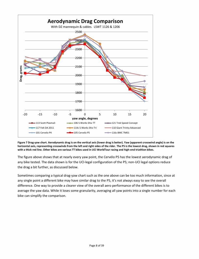
Figure 7 Drag-yaw chart. Aerodynamic drag is on the vertical axis (lower drag is better). Yaw (apparent crosswind angle) is on the horizontal axis, representing crosswinds from the left and right sides of the rider. The P5 is the lowest drag, shown in red squares with a thick red line. Other bikes are various TT bikes used in UCI WorldTour racing and high-end triathlon bikes.
The figure above shows that at nearly every yaw point, the Cervélo P5 has the lowest aerodynamic drag of
any bike tested. The data shown is for the UCI-legal configuration of the P5; non-UCI legal options reduce
the drag a bit further, as discussed below.
Sometimes comparing a typical drag-yaw chart such as the one above can be too much information, since at
any single point a different bike may have similar drag to the P5, it’s not always easy to see the overall
difference. One way to provide a clearer view of the overall aero performance of the different bikes is to
average the yaw data. While it loses some granularity, averaging all yaw points into a single number for each
bike can simplify the comparison.
1600
1700
1800
1900
2000
2100
2200
2300
2400
2500
-20 -15 -10 -5 0 5 10 15 20
Dra
g, g
ram
s
yaw angle, degrees
Aerodynamic Drag ComparisonWith DZ mannequin & cables. LSWT 1126 & 1206
113 Scott Plasma3 106 S-Works Shiv TT 121 Trek Speed Concept
117 Felt DA 2011 114c S-Works Shiv Tri 110 Giant Trinity Advanced
101 Cervelo P4 105 Cervelo P5 116c BMC TM01

Page 9 of 39
Figure 8 Average drag of the same bikes in the drag-yaw chart above.
The figure above compares the average aero drag of the P5 against the so-called “superbikes” and more
typical tri bikes. The chart shows that the P5 has 41 to 108 grams less average drag than the “superbikes.”
The savings is even greater compared to typical tri bikes. This reduction in aero drag means the P5 can save
you power or time.
How much power can the P5 save?
This drag reduction saves roughly 4 to 11 Watts compared to the “superbikes.” The savings is even greater
compared to typical tri bikes.
How much time can the P5 save?
In a 40 km race, this drag reduction saves roughly 16 to 43 seconds compared to the “superbikes.” The
savings is even greater compared to typical tri bikes.
P5 Aero Design Elements How does the Cervélo P5 achieve this low drag? A few of the many aero design elements in the P5 are
discussed below.
TrueAeroTM library
In general, a good aero bike uses airfoil tube sections. (This may seem obvious, but many “aero styled” bikes
have arbitrary, “made-up” tube sections that can actually increase drag.) In Cervélo’s early days, “aero
sections” meant NACA (National Advisory Committee for Aeronautics) airfoils.
Figure 9 Airfoil thickness and chord. Thickness in bicycle frame aerodynamics refers to the distance between the two airfoil surfaces. Chord is the distance from the leading edge to the trailing edge. Longer chord airfoils nearly always have lower aero drag.
19501975200020252050207521002125215021752200
Ave
rage
Dra
g, g
ram
sAverage Drag Comparison
With DZ mannequin & cables. LSWT 1126 & 1206

Page 10 of 39
We still use some NACA foils where they make sense, but in our long quest to help our clients go faster,
we’ve spent enough time studying bicycle aerodynamics to not only design a family of our own aerodynamic
sections that improve on NACA (our TrueAeroTM library of airfoils), now we’ve arrived at the next generation
of aero design. We no longer design just a tube section (two-dimensional) – we now design entire bike
frame skin surfaces (three-dimensional), taking into account the different air flow characteristic in each aero
zone.
Aero zone design
Designing skin surfaces instead of two-dimensional cross sections may seem like a subtle difference, but the
aero zone design concept changes the whole design approach, with another jump forward in performance
as a result. Because of the presence of the rider and various bike components and their downstream effects,
there are significant differences in flow in different areas of the bike. Different flows call for different
airfoils; just one foil, used everywhere, is not optimal. Designing a bike with different tube shapes in
different zones makes perfect sense and can gain the athlete a significant speed advantage.
Figure 10 Some aero zones. Handlebar is in relatively clean air. Head tube and fork follow the brake. Down tube is in the wake of the front wheel. Seat post and seat tube are in the wake of the athlete’s body. Blue is low velocity, red is high velocity.
As you can see from the CFD analysis result above, airflow in each aero zone is different. For example, the
lower part of the seat tube leads air onto the rear wheel; the fork crown and head tube guide air coming off
the front brake, etc. Aerodynamic requirements are different in each aero zone; therefore we use different
airfoils in each aero zone. A few examples follow.
Head tube aero zone
The P5’s head tube greatly affects aero performance. At the base of the head tube, the thickness is driven by
the various brakes expected to be used, with the Magura RT series hydraulic brake as the optimum. The fork
crown, head tube and down tube follow behind the brake and their profiles complete the TrueAeroTM shape
that reduces drag.

Page 11 of 39
Figure 11 Left: The TrueAeroTM sections encompassing the Magura front brake, head tube and what will later become the down tube. Center: Final head tube thickness and chord designs are optimized as an assembly together with the brake and headset. Right: Validation in the wind tunnel.
Research carried out using CFD and wind tunnel prototypes of various thicknesses (including several very
narrow head tubes) demonstrated the perfect head tube width to be used in the P5. The best width is wider
than some popular superbikes’ head tubes; and this permits the P5 to use a standard 1 1/8” (28.6mm)
diameter fork and headset, thus increasing stiffness, reducing weight and vastly simplifying this aspect of
owning and maintaining a P5 compared to other “superbikes,” many of which require proprietary forks,
bearings, stems, handlebars and other parts.
Together with the slightly thicker head tube, the chord can also grow longer while maintaining the optimum
aero profile, to provide a significant reduction in aero drag while adding stability, especially in cross winds.
Figure 12 Comparison of chord length in the head tube aero zone. The P5 chord is nearly double that of the P4.
Seat tube aero zone
As part of our aero zone research, we’ve isolated areas where slightly unconventional airfoil shapes can
work well, again taking into account the local airflow. Specifically, it’s rare that a truncated airfoil works well
in typical flows, since the aft low pressure recirculation zone “sucks” on the back of the object, adding drag
by “pulling” backward on the frame or component’s rear-facing surfaces.
Page 12 of 39
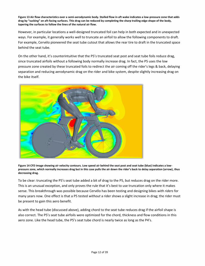
Figure 13 Air flow characteristics over a semi-aerodynamic body. Stalled flow in aft wake indicates a low-pressure zone that adds drag by “sucking” on aft-facing surfaces. This drag can be reduced by completing the sharp trailing edge shape of the body, tapering the surfaces to follow the lines of the natural air flow.
However, in particular locations a well-designed truncated foil can help in both expected and in unexpected
ways. For example, it generally works well to truncate an airfoil to allow the following components to draft.
For example, Cervélo pioneered the seat tube cutout that allows the rear tire to draft in the truncated space
behind the seat tube.
On the other hand, it’s counterintuitive that the P5’s truncated seat post and seat tube foils reduce drag,
since truncated airfoils without a following body normally increase drag. In fact, the P5 uses the low
pressure zone created by these truncated foils to redirect the air coming off the rider’s legs & back, delaying
separation and reducing aerodynamic drag on the rider and bike system, despite slightly increasing drag on
the bike itself.
Figure 14 CFD image showing air velocity contours. Low speed air behind the seat post and seat tube (blue) indicates a low-pressure zone, which normally increases drag but in this case pulls the air down the rider’s back to delay separation (arrow), thus decreasing drag.
To be clear: truncating the P5’s seat tube added a bit of drag to the P5, but reduces drag on the rider more.
This is an unusual exception, and only proves the rule that it’s best to use truncation only where it makes
sense. This breakthrough was possible because Cervélo has been testing and designing bikes with riders for
many years now. One effect is that a P5 tested without a rider shows a slight increase in drag; the rider must
be present to gain this aero benefit.
As with the head tube (discussed above), adding chord to the seat tube reduces drag if the airfoil shape is
also correct. The P5’s seat tube airfoils were optimized for the chord, thickness and flow conditions in this
aero zone. Like the head tube, the P5’s seat tube chord is nearly twice as long as the P4’s.

Page 13 of 39
Figure 15 Comparison of chord length in the seat tube aero zone. The P5 chord is nearly double that of the P4.
Both the head tube and seat tube of the P5 are thicker and longer chord than the P4. But these dimensional
changes alone are not actually the main drivers of the P5’s low aero drag performance - of course just
sketching a seat tube that’s a few millimeters thicker and twice as long won’t necessarily make a bike faster,
you also have to know what shapes to outline to those dimensions. In fact the shapes of the P5 seat tube’s
surfaces are driven by several different section profiles, which vary significantly up and down the length of
the seat tube following the aero zone principle depending on the airflow conditions at each are, and taking
into account bike and body parts that are nearby (legs, spinning wheels, derailleur, etc.). The curvatures of
each section’s profile are iteratively engineered following the results of the finely-tuned CFD analysis.
Figure 16 TrueAeroTM cross sections in the P5’s seat tube aero zone, illustrating a series of truncated foils in the lower skin surface (for the rear tire) and different truncated foils in seat post and upper seat tube skin surfaces which reduce aero drag in this location.
Hidden Pocket
The P5 is integrated for Di2 installation, including internal cables and battery completely hidden inside the
frame’s “hidden pocket.”

Page 14 of 39
Figure 17 Left: Transparent CAD image showing where the Di2 battery (red) fits inside the hidden pocket storage compartment built into the P5’s frame. Right: Photo showing the door covering the hidden pocket.
The original Shimano Di2 battery and holder are neatly hidden inside the P5’s seat tube, above the bottom
bracket: the “hidden pocket.” This is an aero benefit, since a typical external Di2 battery can add up to 11
gramsii of aero drag. And unlike a custom battery, using Shimano’s original battery and connectors keeps
Shimano’s Di2 warranty intact.
To access the hidden pocket, remove the rear wheel and unscrew the cover. The battery slides out easily.
Electrical cables are also inside the frame, neatly connected to the battery.
If the P5 is assembled without Di2, then the hidden pocket is available to store other things, such as a spare
inner tube, etc.
Fork chord options
The features described so far are frame features, but the frameset also includes the fork. There are two
forks designed for the P5: the P5-Three and the P5-Six.
The first, the P5-Three fork, has fork blades with a three to one (3:1) aspect ratio and has been officially
approved by the UCI as part of the P5 frameset. The P5-Three fork uses the same TrueAeroTM fork blade skin
surfaces as the highly aerodynamic Cervélo P4 family of forks, thus leveraging the years of aero research
that went into developing them, as described in the answer “The P4 Fork, a Prodigious Father” in the Ask the
Engineers section of the cervelo.com websiteiii.

Page 15 of 39
Figure 18 Left: the Cervélo P5-Three fork, 3:1 blades and UCI legal. Right: The Cervélo P5-Six fork, 6:1 blades and UCI-illegal.
The second, the P5-Six fork, extends the fork blades chord dimension to increase the aspect ratio up to six to
one (6:1) which of course is not UCI legal, but reduces average drag by about 10 gramsiv.
For simplicity, both forks are designed to work in the P5 frame with standard headsets, brakes and stems.
The two forks are functionally interchangeable.
Stiffness
BBright™ is the first Bottom Bracket standard that uses an oversize 30mm axle and allows for oversized
frame tubes (up to 16% wider than standard bottom brackets). It offers the optimal combination of stiffness
and weight for the overall system (crankset and frame together).
For more information about BBright, please visit http://bbright.net/.
BBright helps make the P5 20% stiffer in the bottom bracket than the P4. A stiffer bottom bracket helps
reduce frame flex during pedaling.

Page 16 of 39
Figure 19 Chart comparing bottom bracket stiffness of the P2 (172), P3 (172) , P4 (174) and P5 (209 N/mm).
The P5 is also 32% stiffer in torsion. Torsional stiffness gives you more stability and precise steering control.
This beneficial increase is a natural byproduct of the larger frame tube dimensions driven by the aero
features described above. With the P5 you get to eat your cake and have it, too.
Figure 20 Chart comparing torsional stiffness of the P2 (73), P3 (72) , P4 (76) and P5 (101 N*m/degree).
P5 Frameset Features
Wide fit range A fast tri bike is fastest when the athlete can comfortably stay in the aero position. Together with the new
aero bar, the P5’s new frame geometry (see appendix) accommodates a wider range of athlete fit
coordinates, including arm pad stack heights from 525mm to 742mm. Since rider fit includes both the frame
and bar, we’ll discuss fit more later.
ComfortPlyTM technology Cervélo’s ComfortPlyTM technology is a technique gained from the intense composite analysis skills learned
through our experience with Project California. For ComfortPlyTM, we’ve used the same composite analysis
software tools not only to optimize strength, stiffness and weight, but also to tune frame properties in
different directions. During layup development, once strength and stiffness targets are achieved,
ComfortPlyTM tech actually removes unneeded material to reduce weight, vibration and improve ride quality.
As a result, the P5 is the best riding tri bike we’ve ever made. This is especially important for fresh legs on
the run.
Low friction Internal Cable Stops (ICS3) Exposed cables can spoil the airflow on the best designed aero bike, adding up to 40 grams of aero drag, so
internal cables are a must for aerodynamic performance. But sometimes internal routing can add too much
friction. When engineering the P5, cable routing was planned from the first design stages to minimize bends
and maximize shifting performance, making life with the P5 easier by reducing shift problems and extending
cable maintenance intervals. Low cable friction also contributes to better shifting and braking control.

Page 17 of 39
Figure 21 CAD image showing the P5 frameset’s low friction integrated cable routing.
In the figure above, you can see that shift and brake cable housings enter the frame’s top tube and stop a
few centimeters below the surface at the internal housing stops. From there, lightweight and rigid stainless
steel tubes guide the inner wires through the perfect curve and point them in the perfect direction toward
the BB guide. The inner cables are free inside the down tube, with no friction-causing cable housing or tubes
that can clog. By eliminating the housing, not only do we eliminate friction, but we also eliminate over 100
grams of unnecessary weight. At the bottom bracket, the P5 uses Cervélo’s “single bend” concept in the BB
guide, eliminating the friction-inducing sideways bends many cable guides incur.
Fork accepts all brakes When Cervélo and Magura began to collaborate on the P5 brake, we agreed on a standard center bolt
mount. Although the P5 is designed to be an optimum aero match with the Magura brake, one of the
benefits of a center mount is that a P5 owner can choose any standard brake caliper for the front.
Figure 22 The P5 forks accept any modern road brake that mounts on the traditional center bolt. Left to right: Magura, side pull and center pull.
The rear brake mounts under the bottom bracket and also uses a standard center bolt mount. Either the
Magura or a TRP center pull style brake can be installed in the back.
All-tires cutout We’ve long known the aerodynamic benefits of a properly engineered rear wheel cutout. With a well-
designed seat tube skin surface, the aero sweet spot for best performance is a two to six millimeter gap

Page 18 of 39
between the tire and seat tube. Within this range, aero drag is insensitive to tire-frame gap. Thanks to the
newly engineered TrueAeroTM sections defining the P5 seat tube, the P5 fits tires up to 25mm and carries no
drag penalty with tires up to 23mm wide. This makes it easy for the P5 rider to benefit from the lower rolling
resistance and increased comfort that wider tires can provide.
Figure 23 The all-tires cutout improves aerodynamic performance with wider tires.
Fits all wheels The P5 frame and forks are compatible with all known racing and training wheels as of the time of this
writing, including wide aero wheels and disc wheel covers.
Fork compatibility The P5 frame and forks are designed for a standard 1 1/8” (28.6mm) IS headset. This means the frame
accepts standard headset bearings and the fork accepts standard headsets and stems. This gives complete
compatibility for easy maintenance, easy parts availability and easy stem choices without the hassles,
limitations and high prices of integrated forks, special headsets and mandatory proprietary stems and bars.
Aero bar

Page 19 of 39
Figure 24 The P5’s aero bar, ridden to GC victoy in the Giro d’Italia by Ryder Hesjedal.
The P5’s aero bar, designed by Cervélo and manufactured by 3T, is the fastest aero bar we’ve ever tested,
UCI legal or not. The aero bar has 3:1 airfoils everywhere and complies with every UCI regulation. The aero
bar is also simple, with very few parts; and highly adjustable, with interchangeable arm pad risers and aero
bar extensions. The name of the bar is “Aduro,” from Latin, meaning to ignite, or to set on fire.
The simultaneous tasks of reducing aero drag and being highly adjustable to accommodate a wide range of
riding positions, while remaining easy to work with, are difficult design objectives. Cervélo engineers came
up with a brilliant solution that is the fastest UCI legal aero bar we’ve ever tested, while still being simple to
assemble, adjust and travel with. Compared to other companies’ aero bar designs, the Aduro aero bar is
more aero while being highly adjustable, all while using easily interchangeable sizing parts, all of which are
included.
Adjustability: fit = fast For best performance, a tri bike must fit the athlete’s best aero riding position. To that end we’ve given the
Aduro aero bar a very wide range of adjustability and interchangeability.
Arm pad stack adjustment
One of the most critical fit coordinates is arm pad stack. Arm pad stack is the vertical distance from the
bottom bracket to the top of the support plate for the arm pad. This coordinate has a direct effect on the
athlete’s frontal area, and hence aerodynamic drag. It’s important to remember that frame stack isn’t the
only determinant of arm pad stack; in fact arm pad stack is the sum of the assembly of bike parts: frame,
headset, stem and handlebar.
The Aduro aero bar has three “macro” height settings using interchangeable arm pad risers and up to 55mm
of “micro” height settings using fork spacers in steps as fine as 5mm for an astonishingly wide total range of
12cm of arm pad stack.
Figure 25 The Cervélo-designed 3T Aduro aero bar is adjustable via three interchangeable “Macro” height settings, plus “micro” fork spacers as small as 5mm.
Macro setting Stack, mm
High-V 105
Low 60

Page 20 of 39
X-Low 40
Table 1 The arm pad stack of each Macro setting part.
Figure 26 Left to right: X-lo, Low, High-V. The handlebar extensions attach to the arm pad support, which means they go up and down with the arm pads so they are always at the right height for the athlete’s hands.
In addition to the three Macro height settings, Micro height adjustments are accomplished with fork spacers
in thicknesses of five and ten millimeters. These fork spacers are an aero match with the profile of the stem
so have no aero penalty compared to a bigger frame size.
Figure 27 Left to right: “Low” macro setting with no spacers; “Low” macro setting with 50mm of spacers; “High-V” macro setting with no spacers; “High-V” macro setting with 50mm of spacers.
The spacers are keyed to the stem and to each other to maintain a good aero match.
Arm pad reach adjustment
In addition to arm pad stack adjustment, arm pad reach is adjustable. To keep the Aduro light and efficient,
the base bar and stem are integrated into one structural piece. As shown in the figure above, the horizontal
stem length is fixed at 90mm, but the arm pad plates have multiple holes allowing +25mm or -25mm reach
adjustment for effective stem lengths of 65mm and 115mm.

Page 21 of 39
Figure 28 Aduro arm pad plates showing four rows of holes. These permit fore and aft adjustment of 25mm in either direction.
Arm pad lateral adjustment
There are three lateral spacing options, achieved with multiple holes in the arm pad plates. Measured center
to center they are 145mm, 175mm and 205mm.
Arm pad rotational adjustment
As can be seen in the figure above, each pair of arm pad holes includes one oval slot, which lets the athlete
rotate the arm pad to align with the forearm.
Extension adjustment
After the arm pads, aero bar extensions are the most important for fit. Cervélo engineers chose an industry-
standard 22.2 mm (7/8”) diameter for the extensions, making them interchangeable with all 3T extensions
(straight, s-bend or ski-bend) and with most other extensions on the market as well. The extensions attach
to the arm pad support, so rise and fall together with the arm pads as arm pad stack is adjusted, always
keeping the extensions at the perfect height. The extensions telescope fore and aft with infinite adjustability
and are fixed in place by an aero collet (yes, the nut has a real airfoil shape). Since they are round, the
extensions are rotationally adjustable to match the athlete’s preference.
Base bar reach
From the steerer tube clamp, horizontally to the front edge of the base bar grip area, is 230mm.
Figure 29 Same figure as above, showing base bar reach at 230mm from the steerer tube to the forward face of the base bar grip.
Simple: Fewer parts

Page 22 of 39
One company’s tri bike comes with a tray full of small parts, and you still can’t adjust or exchange the
extensions. Another has six different proprietary stems and accepts no others. In contrast, the Aduro aero
bar has fewer parts, as well as completely adjustable and interchangeable arm pads and adjustable and
interchangeable aero bar extensions.
Figure 30 Left: Aduro aero bar, quite simple. Center: Other brand aero bar; stems sold separately. Right: Other brand aero bar; non-adjustable extensions and a mix of multiple sizes of hex & Torx fasteners.
Frame + bar = aero fit Taking both frame and handlebar into account, we can now compare the fit range for the P5 to a benchmark
P4 set up with a relatively low position using a typical 15mm top cap, 90mm -6 degree stem and 3T aero
bars.
Figure 31 A typically equipped 56cm P4 with low position has an arm pad stack dimension of 604mm.

Page 23 of 39
Figure 32 The same size 56cm P5 with “Low” macro height setting has essentially the same arm pad stack at 601mm.
Figure 33 Again the same size 56cm P5, now with the “X-Low” macro height setting. The arm pad stack drops 20mm lower to 581mm.
From the figures above it is shown that the P5 frame plus Aduro aero bar can easily accommodate quite a
low riding position.
As mentioned above, the Aduro aero bar also goes higher, making the highest arm pad stock on this 56cm
P5 694mm, a few millimeters higher than a 56cm P2 with 120mm upturned stem and the maximum allowed
fork spacers.
See the “Arm Pad Stack & Reach Table” in the appendix for a simple, easy-to-use reference table listing the
full range of arm pad stacks and associated reaches covering every combination of frame size, macro and
micro height handlebar settings.
Aerodynamics: Faster

Page 24 of 39
As mentioned above, for best performance a tri bike must fit the athlete’s best aero riding position. The
Aduro’s designed-in adjustability described above is a big part of that, but there’s more to a fast aero bar
than fit.
Skin surfaces: Cervélo engineered We’ve been testing aero bars for over 10 years in the wind tunnel. We’ve run hundreds of CFD analyses of
different bikes and aero bars. We’ve learned the importance of making the design of the aero bar an integral
part of the P5 development from the very beginning.
During design of the aero bar for the P5, we considered lots of aero bar design concepts including integrated
frame-headset-fork-bar systems. In the end we achieved the best performance without the complexity of a
special headset.
In handlebar design, the first thing to realize is that the handlebar aero zone has relatively undisturbed flow,
so the ideal shape is relatively simple and clean. The Aduro’s skin surfaces are simple and cleanly shaped
airfoils, appropriate for this aero zone.
Figure 34 The TrueAeroTM section profiles and the smoothly blended junctions help make the Aduro aero bar aerodynamically fast.
Next is to determine the impact of other design parameters.
Figure 35 Wind tunnel test prototype for a fully integrated fork, frame, headset, brake and stem concept. It was abandoned in favor of the final P5 concept.
For example, we conducted an aerodynamic study to determine the relationship between head tube
thickness and aerodynamic drag for a complete bicycle including front brake and spinning wheels.

Page 25 of 39
Figure 36 One of a series of SLA models used to measure the sensitivity of aero drag to variations in head tube thickness.
After a dozen CFD analyses, subsequently confirmed by testing SLA prototypes in the wind tunnel (see figure
above), we knew the range of head tube thicknesses that give the least aero drag. Since the optimum
included enough space for a standard fork and headset, we abandoned initial plans for an integrated hinge-
style fork arrangement that would not have reduced aero drag, but spoiled interchangeability and required
proprietary parts and difficult assembly and maintenance procedures. In the end, we finalized the simple
and fast Aduro aero bar design you see now.
Aero-matched with frame and brake Another reason the Aduro is faster is the interface between the bar’s stem portion and the rest of the bike is
a good aero match: airflow is consistent across the different components’ surfaces, making the whole bike
faster.
Figure 37 The aero bar’s stem is an aero match with the P5 frame and brake.
As can be seen in the figure above, the aero bar is completely integrated into one aerodynamic body with
the P5’s brake, fork and frame.
Even the five and ten millimeter “micro” spacers have a TrueAeroTM profile to match, so adding spacers
doesn’t add drag compared to the same arm pad stack with fewer spacers on a bigger frame.

Page 26 of 39
Figure 38 Aduro fork spacers are an aero match with both the stem and P5 frame.
100% hidden cables The Cervélo P5 aero bar is the only current aero bar we know of with 100% hidden cables, both brake and
derailleur. Exposed cables can add up to 40 grams of aero drag and spoil the flow over a well-designed aero
frame shape, so taking the cables out of the wind is critical for good aerodynamic performance.
Figure 39 Cables are 100% internal, and low-friction cable routing is integral to the aero bar’s design.
The aero bar is compatible with mechanical and hydraulic brakes, and mechanical and electronic shifting, all
with 100% internal routing.
The internal cable routing doesn’t come at the price of increased friction though. The High-V macro height
setting shown in the figure above is a good example. Cable routing was a strong consideration from the very
beginning of the design, and one benefit of the V-shaped arm pad risers is the smooth cable path. Lower
cable friction means better shifting, easier tuning and longer intervals between cable services.
Compatible with both brake cable styles

Page 27 of 39
The base bar is completely open inside, with no guide tubes that limit brake lever cable routing choices: the
Aduro works with internal cables that enter the bar through the front or bottom of the grip area.
Fully integrated for Di2 Like the P5 frame, the Aduro aero bar is also Di2 ready, with shift wires routing through the extensions and
stem, directly into the frame through the ICS passage in the top tube. The Di2 cables follow a path similar to
the mechanical cables illustrated above.
The Di2 junction box fits inside the stem near the front of the base bar under the bolted cover. Optionally, if
you want to have access to the junction box at all times, it can be attached outside the stem. The Aduro aero
bar has a Di2 cable exit port at the aft edge of the stem to let the cables out.
Figure 40 Left: Internal space inside the stem. Right: External installation option.
Brakes: Aerodynamics by Cervélo, hydraulics by Magura To go fast, you need good brakes. Speed management is one key to going faster, especially on technical
courses. Other keys to speed are light weight, powerful braking that’s easy to control precisely, and low
aerodynamic drag. Cervélo and Magura partnered together to develop the modern hydraulic road brake,
faster in every way: lighter, more powerful, better modulation and lower aerodynamic drag.
Brake development: caliper Concept sketches and CAD design iterations for the brake caliper, or slave cylinder, are shown below.
Figure 41 Early brainstorm sketches were soon transformed into a first CAD concept.

Page 28 of 39
Air flow in the head tube aero zone is strongly influenced by the dimensions and design of the front brake.
As the brake design neared final dimensions, the P5 fork, head tube and down tube could begin to take
shape.
Figure 42 A new TrueAero profile was analytically developed for the head tube to achieve an aero match with the brake.
Brake development: lever The brake lever, including master cylinder, was not neglected. As with the caliper, hydraulic and mechanical
design took place concurrently with aero engineering.
Figure 43 Like the caliper, evolution of the lever design led to aesthetic, functional and aerodynamic improvements.
In the figure above, lever design began on the left with a basic hydro-mechanical design that the engineers
evolved into the final design on the right. The smooth bump on top also serves as a small hand stop at the
front of the aero bar, making an upturn on the base bar unnecessary and lowering the aero drag.
In the beginning, lever layout was wide open. This is where CFD shines: when physical parts for the wind
tunnel don’t exist yet. In the figure below you can see three of the many lever orientations we considered.
Initially the small horizontal airfoil shaped lever seemed promising, but the presence of the rider’s arms
above the base bar drives the flow downward, preventing the base bar from truly drafting behind the small
lever. One seemingly obvious fix is to thicken and enlarge the lever. While increasing the thickness and
chord helps the base bar draft, it simply adds back the frontal area on the lever itself. We also considered
five concepts with a more traditional lever placement. We chose the fastest lever for the final design: open
faced. The open faced lever is simultaneously more ergonomic (the flat bottom of the lever blade is located
where you expect it and the broad surface is easier on the fingers than some very thin levers) and has less
aero drag: the open face and TrueAeroTM blade profile reduce the turbulence and drag compared to other
designs.

Page 29 of 39
Figure 44 small horizontal lever (left), large horizontal (center), open face lever (right)
Results The final result of the cooperation between Cervélo and Magura engineers is the finished product, the RT
(Road Team) series hydraulic brakes: The RT8 TT and RT6 TT.
Figure 45 Besides color, the RT8 and RT6 differ only in that the RT8 has carbon fiber lever blades and aluminum pivot bolts, while the RT6 has slightly heavier aluminum blades and steel pivot bolts.
The Magura RT6 and RT8 TT brakes out-perform every brake tested, in every category of performance:
weight, braking power, modulation and aerodynamics.
Lighter Weight of a braking system is more than the weight of caliper + levers: the cables and housings must also be
included. For mechanical brakes, cable and housing are mostly steel and quite heavy: up to 70 grams per
meter. In contrast, hydraulic hose weighs about 7 grams per meter, including the hydraulic fluid inside. This
helps make the RT8 TT hydraulic braking system lighter than the top of the line mechanical braking systems
from the two most popular component makers.
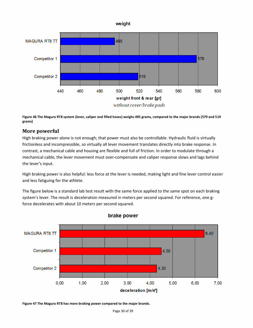
Page 30 of 39
Figure 46 The Magura RT8 system (lever, caliper and filled hoses) weighs 495 grams, compared to the major brands (579 and 519 grams)
More powerful High braking power alone is not enough; that power must also be controllable. Hydraulic fluid is virtually
frictionless and incompressible, so virtually all lever movement translates directly into brake response. In
contrast, a mechanical cable and housing are flexible and full of friction. In order to modulate through a
mechanical cable, the lever movement must over-compensate and caliper response slows and lags behind
the lever’s input.
High braking power is also helpful: less force at the lever is needed, making light and fine lever control easier
and less fatiguing for the athlete.
The figure below is a standard lab test result with the same force applied to the same spot on each braking
system’s lever. The result is deceleration measured in meters per second squared. For reference, one g-
force decelerates with about 10 meters per second squared.
Figure 47 The Magura RT8 has more braking power compared to the major brands.
Page 31 of 39
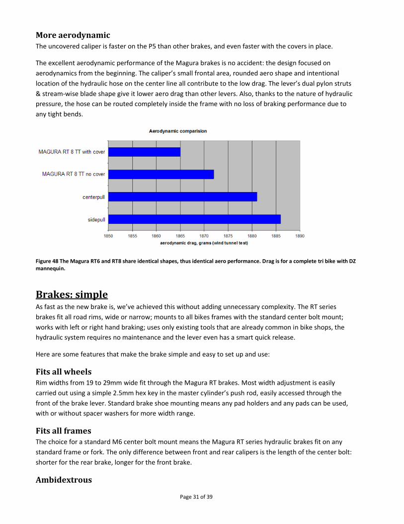
More aerodynamic The uncovered caliper is faster on the P5 than other brakes, and even faster with the covers in place.
The excellent aerodynamic performance of the Magura brakes is no accident: the design focused on
aerodynamics from the beginning. The caliper’s small frontal area, rounded aero shape and intentional
location of the hydraulic hose on the center line all contribute to the low drag. The lever’s dual pylon struts
& stream-wise blade shape give it lower aero drag than other levers. Also, thanks to the nature of hydraulic
pressure, the hose can be routed completely inside the frame with no loss of braking performance due to
any tight bends.
Figure 48 The Magura RT6 and RT8 share identical shapes, thus identical aero performance. Drag is for a complete tri bike with DZ mannequin.
Brakes: simple As fast as the new brake is, we’ve achieved this without adding unnecessary complexity. The RT series
brakes fit all road rims, wide or narrow; mounts to all bikes frames with the standard center bolt mount;
works with left or right hand braking; uses only existing tools that are already common in bike shops, the
hydraulic system requires no maintenance and the lever even has a smart quick release.
Here are some features that make the brake simple and easy to set up and use:
Fits all wheels Rim widths from 19 to 29mm wide fit through the Magura RT brakes. Most width adjustment is easily
carried out using a simple 2.5mm hex key in the master cylinder’s push rod, easily accessed through the
front of the brake lever. Standard brake shoe mounting means any pad holders and any pads can be used,
with or without spacer washers for more width range.
Fits all frames The choice for a standard M6 center bolt mount means the Magura RT series hydraulic brakes fit on any
standard frame or fork. The only difference between front and rear calipers is the length of the center bolt:
shorter for the rear brake, longer for the front brake.
Ambidextrous

Page 32 of 39
Brake levers are symmetrical (there is no left or right), so left or right hand can operate either the front or
rear brake.
No new tools The Magura RT brakes use the same bleed kit as all Magura’s hydraulic brakes. No special tools are needed:
all fasteners use a few different hex key sizes and one T25 Torx®. Spare parts (olives, hydraulic tubing, line
nuts, etc.) are all shared in common with existing Magura rim brakes.
Figure 49 Magura rim brake service kit
Zero maintenance These brakes simply work. Once properly installed, there is no maintenance other than for pad wear or a
few drops of oil in the pivots every few years. The sealed hydraulic system is self lubricating and has no cable
friction, so there is no chance for contamination and no degradation of performance over time.
Unlike DOT brake fluid, the Royal Blood mineral oil used in Magura RT series hydraulic brakes isn’t
hygroscopic, so doesn’t absorb water. The hydraulic fluid never needs to be changed. City bikes with the
same Royal Blood have undergone decades of constant heavy use without any degradation in braking
performance; the only service in many cases has been to occasionally replace the brake pads.
Quick release
Figure 50 Magura RT series quick release.
Magura RT series brakes have a hydraulic quick release at the brake lever. Just flip the small switch down
and the lever and caliper open. It’s safe too: on the first re-application of the brakes, the lever snaps back
into the closed position. No more surprises when you forget to close a cam-type quick release.

Page 33 of 39
Storage & Hydration Staying with the Simply Faster theme, and based on years of testing storage and hydration solutions in the
wind tunnel, the P5 offers a multitude of storage and hydration options. But beyond simply giving the P5
integrated storage and hydration options, we provide information and recommend storage and hydration
locations that are not only convenient, easy to use and sleek, they also make you faster. All are low-drag
options, some are even negative drag options.
Just before the most recent Kona triathlon we were asked about our wind tunnel testing of various storage
and hydration options. Lava Magazine’s article “Free Speed: Cervélo’s Tips on Aerodynamic Hydrationv” is
the result. This article covers some of the basic research we conducted in the wind tunnel to determine
where best to locate an athlete’s hydration or storage. We include wind tunnel data from bottles in front,
bottles behind the rider, and bottles in various locations on the frame.
The main takeaways are: (1) put a horizontal bottle between your arms, (2) add a bottle or two behind the
seat, (3) consider top tube storage. If you have Di2, (4) hide the battery!
One wind tunnel test series we didn’t discuss in the Lava article was the test series we performed back in
2007 to examine the effects of integrating a drinking bladder into the frame. We called this prototype
“Tank” and found that no matter how we routed the straw (up, down, neatly along the aero bar, folded
down, etc.…) it added more drag than a simple round bottle on the down tube. Since the straw made Tank
slower, and the bladder presented other complications (how to suck out the fluid? How to clean it? How to
refill it on the fly? How to keep the straw in place yet handy?), we decided to abandon the integrated
bladder concept in favor of hydration and storage solutions (see below) that are both simpler and faster.
Based on the same wind tunnel testing described above, as well as new testing and analysis from the P5
development project, we’ve designed the P5 to integrate hydration and storage in sleek and intuitive ways,
all of which have minimal drag and some of which have negative drag!
The P5 has five main storage locations:
1. Between the arms
2. Top tube
3. Down tube
4. Hidden Pocket
5. Behind the saddle
Figure 51 Schematic showing the five main storage & hydration options on the P5.

Page 34 of 39
Bottle between the arms Since using a horizontally mounted round bottle between the arms has been shown to reduce aero drag
significantlyvi, the P5 aero bar includes an option to mount a standard water bottle cage in the perfect
position. The front bolt screws into the horizontal bridge, and the rear screws into the optional plate
(mountable under the elbow pads). If you don’t want to mount a cage here, simply leave off the plate and
the bridge remains as an optional computer mount.
The bosses fit any standard cage and bottle. The bottle is held in the same horizontal plane as the arms, and
the bottle fills in the otherwise turbulent recirculation zone behind your hands that normally adds drag.
Filling in this space with the bottle reduces drag by up to 56 grams. If you’re thirsty, carry a bottle between
your arms. If you’re not thirsty, carry a bottle between your arms.
Figure 52 Cervélo P5 aero bar (Low arm pad configuration), showing integrated bottle cage mount.
Bottle(s) behind the seat Mounting one or two bottles or other objects behind the saddle is a good way to add capacity with a low
chance of adding drag. Details are available in “Ask the Engineers: Hydration and Aerodynamics”
The P5’s seat post head includes a cylindrical hole where the seat clamp slides. If your saddle position
doesn’t require the clamp to be in the farthest rearward position, then that part of the hole is available to
mount X-Lab’s accessory mount. This is a simple and reliable attachment method that also makes the P5
simpler and faster.

Page 35 of 39
Figure 53 Behind the saddle water bottle mount accessory.
Hidden Pocket The P5 frame incorporates a hidden pocket for the Di2 battery, as described earlier.
Top tube storage box The P5 frame includes two M5 threaded bosses on the top of the top tube. These bosses are positioned at
the de facto industry standard location. The forward bolt is about 85mm behind the base of the stem and
the second bolt is 64mm behind the first.
Figure 54 Two bolts in the P5 top tube (left). Prototype X-Lab storage and hydration accessories installed on the P5 (right).
Simply adding these bosses to the P5 top tube makes it easy to securely carry needed supplies in such a
convenient location. The bosses also make you faster by eliminating the Velcro straps commonly used to
attach bags to the top tube.

Page 36 of 39
Figure 55 CFD images showing the low-speed turbulent flow behind the stem (left) replaced with aero matched storage box (right).
Down tube bosses The P5 also has the imminently useful standard bottle cage bosses on the down tube. An aero bottle adds 33
gramsvii of drag. A round bottle adds about 50 gramsviii. Down tube bosses are simple: standard spacing fits
standard cages and bottles. But we’ve added a third boss on the down tube gusset: this further stabilizes the
optional TorHans aero bottle (also useful as storage), which is nearly completing development as of the date
of this writing.

Page 37 of 39
Arm Pad Stack & Reach
Definitions Arm Pad Stack is measured vertically from the center of the bottom bracket to the top of the arm pad base
plate (excluding foam padding).
Arm Pad Reach is measured horizontally from the center of the bottom bracket to the center of the arm
pad support plate. Note the P5’s arm pad support plate has four rows of bolt holes, giving three mounting
positions that affect arm pad reach: 0, +25mm, -25mm.
How to measure Arm Pad Stack & Reach To duplicate your current bike’s arm pad stack & reach, measure your existing bike as follows:
Arm Pad Stack:
1. Measure vertically from the floor to the arm pad base plate. This is dimension A. A = __________
2. Measure vertically from the floor to the bottom bracket. This is dimension B. B = __________
3. Subtract the second number from the first number. This is arm pad stack, C. A – B = C = __________
Arm Pad Reach:
Position your bike’s back wheel against a vertical wall.
1. Measure horizontally from the wall to the center of your arm pad. This is dimension D. D = __________
2. Measure horizontally from the wall to the center of the bottom bracket. This is dimension E. E = __________
3. Subtract the second number from the first number. This is arm pad reach, F. D – E = F = __________
How to use Arm Pad Stack & Reach Use your current arm pad stack and reach numbers in the following table to see which Cervélo P5 sizes can duplicate your current arm pad position.

Page 38 of 39

Page 39 of 39
End Notes i Serious Cycling, Ed Burke, Human Kinetics 2002 ii Average drag, LSWT 1126 Run 120 vs. 121 iii “The P4 Fork – a Prodigious Father” http://cervelo.com/en_us/news-blog/engineering/article/the-p4-fork--a-prodigious-father/2936/ iv Average drag, UWAL 2008 Run 19 – 9 = -5g (w/o rider) and 20 – 16 = -11g (w/rider); LSWT 1126 Run 125 - 124 = -1g (w/rider) v http://lavamagazine.com/gear/free-speed-cervelos-tips-on-aerodynamic-hydration/#axzz1oeQL8P00 vi http://cervelo.com/en_us/news-blog/article/ask-the-engineers-hydration-and-aerodynamics/2930/ vii Average drag, LSWT 1126 Run 127 vs. 128 viii Average drag, multiple runs over multiple years.