Embed Size (px)
Citation preview

2019 P5 RETAILER ASSEMBLY MANUAL

1 2
This manual is intended to guide official Cervélo retailers, through the assembly and adjustment of the Cervélo P5. This manual outlines the process and procedure associated with the installation of Cervélo components, as well as the routing of shifting and braking control lines only. Proprietary parts referenced in this manual are available only through Cervélo Cycles Inc. directly.
Failure to use the specified parts and follow these assembly instructions may result in loss of control while riding, leading to serious injury. This manual is not intended to replace the assembly and service instruction provided by third-party component manufactures, and assumes that the assembler is a trained, professional bicycle mechanic. See https://www.probma.org/
Important Information .....................................1List of Tools & Supplies ..................................2P5 Parts List .............................................3Frame Features............................................4Small Parts...............................................5Frame Preparation.........................................6Brake Housing Routing .....................................8Electric Cable Routing...................................10Mechanical Cable Routing .................................11Fork Preparation .........................................12Fork Installation........................................13Monoriser Post...........................................15Extension Assembly .......................................16Arm Cup & Pad Installation ...............................17Arm Cup Positions........................................18Monoriser Post Assembly..................................19Monoriser Post Cutting Instructions......................20Monoriser Assembly Installation ..........................21
Extension & Basebar - Di2 Cable Routing .................22Extension & Basebar - eTap Cable Routing ................23Extension & Basebar - Mechanical Cable Routing ..........24Electric Cable Installation ..............................25Mechanical Cable Installation ............................26Top Tube SmartPak Installation...........................27Stem SmartPak Installation ...............................28Seatpost Assembly .......................................29Seatpost Cutting Instructions ............................31Seatpost Di2 Battery Installation........................32Basebar Grip Installation ..............................33Tire Clearance...........................................34Aero Through-Axle Wheel Installation .....................35
Appendix:EX10 Riser ......................................37EX10 Riser Assembly ............................38EX10 Extension Assembly ........................39EX10 Extension Angle Adjustment ................40
CER-P5D-V1.1 - 2019-01-30
TABLE OF CONTENTS
IMPORTANT INFORMATIONNOTE: Cervélo strongly recommends that all assembly and adjustment procedures be performed by an authorized Cervélo retailer. If you are a Cervélo P5 consumer/purchaser reading this manual we suggest that before attempting to undertake any of the procedures in this manual that you consult your authorized Cervélo retailer, or visit us at www.cervelo.com/support
NOTE: This manual was developed to compliment the Cervélo General User Manual, and is intended as a supplement to the assembly and installation instructions supplied by the component manufacturers (provided with this bicycle).
NOTE: All non-proprietary components are available from your local distributor.
LIST OF TOOLS & SUPPLIESThis manual outlines a number of procedures for making optional adjustments to the P5 which differ from the way the bicycle is originally sold by Cervélo.The following tools and parts listed are required for these adjustments. These parts are not available for consumer purchase and are only available for purchase by Cervélo retailers. Cervélo strongly recommends that all assembly and adjustment procedures be performed by an authorized Cervélo retailer.
All parts available for separate purchase are noted in this manual with Cervélo part numbers listed in ALL - CAPS FORMAT, with a full listing provided on page 3. These parts are available by visiting the Cervélo Customer Portal https://dealers.cervelo.com
Tools
Bicycle workstand (types which secure bike by the seatpost, or pro-type stand with fork mount)
Torque wrench(es) with 2.5Nm to 15Nm range and adaptors:
Allen (Hex) head inserts:2mm, 2.5mm, 3mm, 4mm, 5mm, 6mm, 8mm, 10mm
Open ended wrenches:7mm, 8mm, 10mm, 17mm
Cable cutters
Pliers
Tools
Phillips-head screwdriver
Slot-head screwdriver
Pedal wrench
Brake rotor lockring tools
Hydraulic bleed kit
Di2 wire tool – Shimano
Good quality bicycle grease

3 4
A guide to the Cervélo P5 frame.
Rear Dropout Cable Exit, electric and mechanical
Front Derailleur Wire Exit Hole, electric and mechanical
Top Tube InternalCable Port
SmartPak Top Tube Mount Holes
Bottom Bracket Cable Port
FRAME FEATURESP5 PARTS LISTItem Description Cervélo Part No.
Front Derailleur Mount w/ Bolts FDM-0E0
Bottle Boss Cover Plate CVR-WB
Chainstay Protector P Series PRO-CS-P
BB Cable Guide & Cover BBG-0E0
Threaded Axle Fork Insert QRI-THD
Seat Post Clamp Assembly P Series SPC-0E0P
P Series Seatpost Battery Mount MT-BINT-SP
SB03 Top Tube Storage Box SB-SB03-TT
SB04 Stem Storage Box SB-SB04-STEM
Disc Brake Hose Guide CBG-DBH
HB11 Headset HS-HB11
Item Description Cervélo Part No.
Cervélo Front Aero Through Axle QRA-AERO-F
Cervélo Rear Aero Through Axle QRA-AERO-R
HB11 Basebar Assembly HB-HB11
HB11 Stem Top Cap With Bolt STC-HB11
HB11 Stem Cover Cap HBP-HB11-STCVR
Basebar Grips L/R HBP-GRIPS
P5 Riser Post Clamp HBP-PCLP
SP23 Carbon Seatpost With Head SP-SP23
UCI P5 Seatpost SP-CER-UCI-ACB
SP21, SP23 Saddle Clamp Slug SPS-SP2123
Item Description Cervélo Part No.
Seatpost Water Bottle Mount MT-WB-SP
EX11 Monoriser HBP-EX11-RISER
EX11 Di2 Riser Post Plug MT-EX11-DI2
EX11 Riser Post Rests w/ Bolts HBP-EX11-RESTS
EX11 Riser Post Pads HBP-EX11-PADS
EX11 Extensions 50 Degrees HBP-EX11-EXT50DEG
EX11 Extensions 30 Degrees HBP-EX11-EXT30DEG
EX11 Extensions S Bend HBP-EX11-EXTSBEND
EX11 Extension Fixing Wedge w/Bolt HBP-EX11-FW
EX11 Di2 Plate/Mech. Plug w/Bolt HBP-EX11-CVR

5 6
Front Fork Axle InsertQRI-THD
BB Cable Guide/CoverBBG-0E0
Front Derailleur Wire Hole Blanking Plug GR-ST-CLOSED
Disc Hose Bushing x2CBG-DBH
Seatpost ClampSPC-0E0P5
Riser Post ClampHBP-PCLP
Rear DerailleurHanger AssemblyDRH-WMN112
Rear Derailleur Press-In Cable Stop (Mechanical)CBS-DRPOUT
Rear DerailleurWire Guide(Electric)GR-DRPOUT-GUIDE
Rear Derailleur Blanking Plug (Wireless)GR-DRPOUT-CLOSED
Designed to accommodate electronic, mechanical and hydraulic controls, the P5 frame is engineered to provide seamless integration of all shifting systems, regardless of method or brand. In order to do so, you will require the parts shown below. Not all parts will be used, depending on the groupset fitted to the bicycle.
SMALL PARTS FRAME PREPARATION
Lightly grease Rear Derailleur Hanger Fixing Nut and install Rear Derailleur Hanger (DRH-WMN112) finger tight. Final tightening will be done after rear wheel installation.
Lightly grease supplied M4 fixing screw, and install the Front Fork Axle Insert (QRI-THD) to the fork. Torque to 3Nm.
Ensure Front Derailleur Mount fixing screws are torqued to 3Nm.
1. Apply carbon assembly compound to both frame and seatpost.
2. Insert Seatpost Clamp (SPC-0E0P5) fully into frame so it is fully flush with the top tube.
3. Adjust height and torque to 8Nm maximum.
Do not final tighten rear derailleur hanger assembly without rear wheel installed. Doing so will result in a misaligned derailleur and poor shifting.
Hold the frame using a secured seatpost only.
Clamping the top tube can damage the frame and void your warranty.

15mm
7 8
FRAME PREPARATIONClean fork surface with isopropyl alcohol. Remove backing and fix the adhesive Fork Rotation Stopto the fork.
Not installing the Fork Rotation Stop may result in damage to the frame and void your warranty.
It is recommended that the rear hydraulic brake hose or brake cable housing is installed first. These routing illustrations are intended as a supplement to the manufacturer’s installation instructions only. For both hydraulic and mechanical disc brakes, please refer to the component manufacturer’s service center or website for further information.
BRAKE HOUSING ROUTING
Route rear brake hose from chainstay through from Top Tube Internal Cable Port.
Route brake hosefrom bottom of fork up through top*.
Clean the chainstay using isopropyl alcohol. Install the Chainstay Guard by removing adhesive backing, and fixing the guard to the frame. The bottom rearward edge should be approximately 15mm from the edge of the Rear Derailleur Hanger Fixing Nut.
*With Di2 builds, first install the 400mm E-Wire before routing the brake hose.

Chainstayheight: 30mm
9 10
Route hydraulic brake hose or mechanical brake housing through the frame and fork with the Disc Hose Bushings (CBG-DBH). Install and adjust calipers as per manufacturer’s instructions.
BRAKE HOUSING ROUTINGIt is recommended that electric cabling and junction points be installed after the brake hose has been installed. These routing illustrations are intended as a supplement to the manufacturer’s installation instructions only. Please refer to the component manufacturer’s service center or website for further information.
ELECTRIC CABLE ROUTING
Brake E-Wire
Route 1000mm Di2 E-Wire from Top Tube Internal Cable Port out through Bottom Bracket Cable Port.

11 12
It is recommended that front and rear derailleur cables be installed after the brake hose has been installed. These routing illustrations are intended as a supplement to the manufacturer’s installation instructions only. Please refer to the component manufacturer’s service center or website for further information.
MECHANICAL CABLE ROUTING
Ensure that the shifter housing is not twisted together. Add ferrules to the bottom bracket end of the housing.
Brake Rear Shifter Front Shifter
FORK PREPARATIONNote: It is recommended that you familiarize yourself with the steering system before complete installation, by performing a trial assembly without hoses or control cables present.
Install preload insert in fork. Torque to 8Nm Prepare Basebar by
cleaning the seal seat with isopropyl alcohol, and installing bearing seal ring.
For installation of mechanical shifting or SRAM eTap, prepare Stem Preload cap by removing rubber insert.
Your Cervélo frame & fork have been designed to work together. Do not attempt to install an alternative fork.
Route shifter housing from Top Tube Internal Cable Port out through Bottom Bracket Cable Port.

13 14
NOTE: This diagram is for assembly reference only. During complete assembly, hoses and control cables will be present.
Preload Fixing Screw M6 x 30mm
Stem Preload Top Cap(STC-HB11)
1" Upper Bearing
1 3/8" Lower Bearing
Compression Ring
Basebar(HB-HB11)
Basebar Clamping Screw
Fork Clamping Screw
Fork RotationStop
Bearing Seal Ring (affixed to Basebar)
1. Check the Basebar, and headset components to make sure there are no sharp or rough edges on any of the surfaces which could cut or damage the steerer tube. If any rough edges are detected, have the components repaired (sharp edges removed) or replaced before proceeding.
2. Press the lightly greased upper and lower headset bearings into the frame, and insert the fork into the head tube.
3. Slide the compression ring onto the steerer, and down until it fully seats in the top of the upper headset bearing. The split in the compression ring must be oriented toward to left or right side of the steerer – never towards the front or back.
4. Clean the seal seat of the Basebar with isopropyl alcohol, and adhere the Seal Ring to the Basebar.
5. Slide the Basebar onto the fork steerer oriented as shown. Note the Basebar must engage both the fork steerer and the external steerer. Do not use grease on the fork steerer. The use of Tacx Carbon Assembly Compound™or equivalent friction paste is recommended to help secure the stem.
FORK INSTALLATION FORK INSTALLATION
6. Lightly grease the threads of the Preload Fixing Screw.
7. Place the Stem Cap on top of the Basebar and insert the greased Preload Fixing Screw through the cap to engage with the star nut. Tighten the bolt only enough to remove all play from the headset, and ensure that the fork still rotates freely.
8. Tighten both the greased Basebar Clamping Screw and Fork Clamping Screw using a torque wrench. Tighten the bolts to a maximum of 5Nm.
9. As a final check ensure that the fork rotates freely in the head tube without any play or binding. If any problem is detected, loosen the bolts and perform steps 7) to 8) again.
Do not exceed the maximum torque specifications listed in this manual. Correct tightening force on fasteners – nuts, bolts, screws – on your bicycle is very important. Too little force, and the fastener may not hold securely. Too much force, and the fastener can strip threads, stretch, deform or break. Either way, incorrect tightening force can result in component failure, which can cause you to lose control and fall.
Basebar Clamping Screw
Fork Clamping Screw

15 16
EXTENSION ASSEMBLYNOTE: This diagram is for assembly reference only. During complete assembly, hoses and control cables will be present.
Apply a light coating of Carbon Assembly Paste to the clamping area of the Extensions, and secure Extension Wedge by tightening the lightly greased M6 x 20mm fixing screw to 4Nm.
S-Bend HPB-EX11-EXTBEND
30˚ J-Bend HPB-EX11-EXT30DEG
50˚ J-Bend HPB-EX11-EXT50DEG
MONORISER POSTNOTE: This diagram is for assembly reference only. During complete assembly, hoses and control cables will be present.
Shimano Di2: Install Junction A and Mounting Plate. Tighten M3 x 10mm screw to 1-2Nm.
Mechanical & SRAM eTap: Install Rear Plug and Mounting Plate. Tighten M3 x 10mm screw to 1-2Nm.
Junction AEW-RS910
EX11 Monoriser Post (HBP-EX11-RISER)
EX11 Monoriser Post (HBP-EX11-RISER) EX11 Monoriser Post
(HBP-EX11-RISER)
50˚J-BendExtension
Extension Wedge (HBP-EX11-FW)
M6 x 20mmFixing Screw
Rear PlugMountingPlate Mounting
Plate
M3 x 12mmFixing Screw
M3 x 12mmFixing Screw

17 18
ARM CUP & PAD INSTALLATION1. Clean Arm Cups with isopropyl alcohol and apply
Velcro sheets.
2. Attach Arm Cups to the Riser Post using two lightly greased M5 Fixing Screws.
3. Torque Fixing Screws to 4Nm.
4. Align the Arm pads with the Arm Cups and press to secure them to the Velcro sheets.
ARM CUP POSITIONS
Bottle Boss Cover Plate
Position: Farthest outside,farthest forward.
Position: Farthest outside,farthest back.Arm Pad
Arm Cup
AdhesiveVelcro
M5 x 12mmFixing Screws
Aerobar water bottle mount,torque M5 x 8mm fixing screws to 2Nm.
Two fixing screws must always be installed per arm cup. The fixing screws must be installed in fore-aft fixing position, and not diagonal.
Failure to use the specified parts and to follow the supplied assembly instructions may result in a loss of control while riding and potentially serious injury.

Frame Size (cm)Trim Amount for Lowest Stack (w/ riser plug)
48 70mm
51 56mm
54 39mm
56 20mm
58 0mm
Max. 70mm
Cut Line
19 20
MONORISER POST ASSEMBLY MONORISER POST CUTTING INSTRUCTIONSWith Monoriser Post pre-wired, connect frame E-Wire to Riser Post E-Wire using EW-JC200 junction, and locate in the Riser Plug pocket.
Push the SM-JC41 4 Port Junction Box into the Basebar after wiring is complete.
Riser Plug w/EW-JC200 2 Port Connector inserted
Press wired EW-JC200 connector into Riser Plug.
1. Use a light coloured grease pencil to accurately mark the cut-off location on the Monoriser Post. See table below for the exact number based on frame size.
2. Insert the Monoriser Post in the Park Tool SG-7.2 Saw Guide (or equivalent) so that the cut-off line can be seen clearly through the blade guide in the tool.
3. Using a blade designed specifically for cutting carbon; proceed with cutting the stem steerer (as per Park Tool’s instructions).
4. Carefully file the cut end removing any rough edges.
Achieving the lowest possible stack may require trimmingthe Monoriser Post. If using a cut Riser Post ensure there is always a minimum of 70mm remaining inside the frame.
If trimming is required, final length should allow for a minimum 70mm of Monoriser Post remaining in the frame. Failure to meet this requirement, may result in damage to the frame not covered by warranty policy, or serious injury to rider.
300mm E-Wire
400mm E-Wire
SM-JC41 4 PortJunction Box

21 22
EXTENSION & BASEBAR - DI2 CABLE ROUTING
Junction AEW-RS910
400mmE-Wire
300mmE-Wire
300mmE-Wire
400mmE-Wire
1000mmE-Wire
EW-JC130Y-Connector
EW-JC200
Brake
E-Wire
MONORISER ASSEMBLY INSTALLATION
SM-JC41 4-PortJunction Box
1. Apply a light coat of carbon assembly compound to Riser Post, and install into fork.
2. Apply a light coat of carbon assembly compound to chevron and rear surfaces of the Riser Post Clamp, and install at rear of Riser Post ensuring that the clamp is fully inserted, and no chevrons are visible.
3. Torque to 8Nm.

23 24
EXTENSION & BASEBAR - ETAP CABLE ROUTING EXTENSION & BASEBAR - MECHANICAL CABLE ROUTING BrakeBrake
Rear ShiftereTap Blip Wire
Front Shifter

25 26
With all wires inside, cap the Bottom Bracket Cable Port with the BB Cable Guide/Cover (BBG-0E0).
Install the Rear Derailleur Wire Guide (GR-DRPOUT-GUIDE).
For wireless shifting systems install the Rear Derailleur Blanking Plug (GR-DRPOUT-CLOSED).
The front cable travels across the non-drive side slot, and in the direction of the seat tube. The rear cable travels along the drive side slot, and along the chainstay. When complete, fix the BB Cable Guide/Cover (BBG-0E0) into place.
Install Rear Derailleur Press-In Cable Stop (CBS-DRPOUT).
As per manufacturer’s instructions, install rear derailleur on rear derailleur hanger, cut appropriate housing length, and attach cable.
MECHANICAL CABLE INSTALLATIONELECTRIC CABLE INSTALLATION
Ensure ferrulesare used to cap shifter housingat BB Cable Guide/Cover.

27 28
TOP TUBE SMARTPAK INSTALLATION STEM SMARTPAK INSTALLATION
M5 x 18mm Torque to 1-2Nm
M5 Washer
M4 x 12mm Torque to 1-2Nm
SmartPakTop Tube Storage(SB-SB03-TT)
Ensure tabs are in place and sides held inward during installation.
SmartPak Stem Storage(SB-SB04-STEM)

29 30
M5 x 16mmFixing Screws
SEATPOST ASSEMBLY SEATPOST ASSEMBLY
Slide the lightly greased seatpost bottle cage mount slug into the seatpost.
If not using the bottle cage mount, use the alternate seatpost slug (SPS-SP2123).
1. Install saddle mount to slug using lightly greased M5 fixing screws.
2. Torque to 6-7Nm.
3. Install lightly greased M6 Rail Binder Bolt, and install saddle.
4. Torque to 12Nm.
5. Determine desired angle, and attach water bottle mount to seatpost slug with M5 fixing screw.
6. Torque to 4Nm.UCI P5 Seatpost(SP-CER-UCI-ACB)
SP23 Seatpost(SP-SP23)
Rail Binder BoltM6 x 55mm
Seatpost Water Bottle Mount(MT-WB-SP)
Attach water bottle cage using lightly greased M5 x 8mm fixing screws. Torque to 2-3Nm.

Cut Line
1cm
1cm
31 32
1. Taking care to maintain the minimum required seatpost insertion of 6.5cm and maximum of 8.5cm, carefully measure and use a light coloured grease pencil to accurately mark the cut-off location on the seatpost.
2. Insert the P Series Seatpost in the Park Tool SG-7.2 Saw Guide (or equivalent) so that the cut-off line can be seen clearly through the blade guide in the tool.
3. Using a blade designed specifically for cutting carbon composite materials (or a fine tooth blade with greater than 32 teeth per inch); proceed with cutting the Seatpost (as per Park Tool’s instructions).
4. Use fine grit sandpaper to carefully remove any fraying or burring from the cut end. Reposition clamp approximately 10cm from the cut end.
5. With a grease pencil, mark a point 1cm from the cut end on the trailing edge of the Seatpost, and another 1cm from the back, on the bottom edge. Draw a line connecting them, forming a 45 degree guideline.
6. Placing the blade of your saw on the grease pencil mark, very carefully proceed to cut, resulting in a 45 degree chamfer being cut onto the trailing edge of the Seatpost.
7. Carefully sand the end and after applying carbon assembly compound, return to the frame.
Note: It is essential that all Cervélo Aero Seatposts, have a 45 degree chamfer cut on the rear trailing edge of the post. If trimming is required after fitting, the following method is recommended.
SEATPOST CUTTING INSTRUCTIONS SEATPOST DI2 BATTERY INSTALLATION
If trimming is required, final length should allow for a minimum 6.5cm of seatpost remaining in the frame. Failure to meet this requirement, may result in damage to the frame not covered by warranty policy, or serious injury to rider.
Press the Di2 battery into the Seatpost Battery Mount (MT-BINT-SP) and attach the E-Wire according to the manufacturers instructions.
Insert the assembled battery and battery mount into the seatpost.
P Series Seatpost Battery Mount(MT-BINT-SP)

33 34
TIRE CLEARANCEYour Cervélo bicycle complies with the ISO 4210-2:4.10.2 standard for tire clearance. In order to comply with these safety standards and maintain your Limited Lifetime Warranty, a minimum of 4mm of clearance must remain between the tire and any frame element. Due to the growing complexity of tire and rim interfaces, Cervélo recommends identifying the available space before choosing a tire.
1. Measure the space between the chainstays at the bottom bracket junction.
2. Measure the space between the seatstays at the top of the tire.
3. Using the smallest of those two numbers, subtract 8mm (4mm per side) to determine the remaining space.
4. With the tire installed and fully inflated on your wheel, measure the tire width to ensure that it fits.
Tire Dimension
Frame Clearance
Contact between the tire and the frame or fork may result in a loss of control while riding and potentially serious injury. Failure to follow these guidelines may result in damage to the frame not covered by Cervélo Limited Lifetime Warranty.
BASEBAR GRIP INSTALLATION
Cervélo Basebar grips are designed to be installed on either right or left hand side, and can be trimmed to meet your needs.
Recommended installation:
1. For the longest reach option, install the grip with Side A facing up.
2. For a 20mm shorter reach, trim grip 20mm behind leading edge, and install grips with Side B facing up.
Cut LineSide A
Side B

35 36
AERO THROUGH-AXLE WHEEL INSTALLATION
Use a 6mm hex keyto tighten/loosen the through-axle.
To secure the front wheel, install the greased axle, through the drive side drop out, through the wheel hub, and rotate to thread axle into opposite fork drop out until tight. Tighten to 12-15Nm.
To secure the rear wheel, install the greased axle, through the non-drive side drop out, through the wheel hub, and rotate to thread axle into opposite fork drop out until tight. Tighten to 12-15Nm.
Perform final tightening on Rear Derailleur Hanger Fixing Nut using a 17mm wrench. This action is unique to initial assembly,and should not require adjustment afterwards.
To ensure rider safety, it is critical to install the Cervélo Aero Through-Axle correctly. Failure to do so may result in a crash, with potential for serious injury to the rider.
Adjust brakes as per manufacturer’s instructions.Adjust shifting as per manufacturer’s instructions.
37 38
APPENDIX: EX10 RISERAn alternative pad-mount and riser system is available for your Cervélo P5, allowing for extension tilt adjustment of 0 degrees, 5 degrees, 10 degrees or 15 degrees. Following is shown the installation procedure, as well as the partcodes required. All items can be ordered from Cervélo directly.
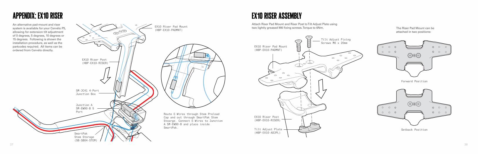
EX10 RISER ASSEMBLY
Setback Position
Forward Position
The Riser Pad Mount can be attached in two positions:
Attach Riser Pad Mount and Riser Post to Tilt Adjust Plate using two lightly greased M6 fixing screws. Torque to 6Nm.
EX10 Riser Pad Mount(HBP-EX10-PADMNT)
EX10 Riser Pad Mount(HBP-EX10-PADMNT)
EX10 Riser Post(HBP-EX10-RISER)
EX10 Riser Post(HBP-EX10-RISER)
Tilt Adjust Plate(HBP-EX10-ADJPL)
Tilt Adjust Fixing Screws M6 x 20mm
Junction ASM-EW90-B 5 Port
SM-JC41 4-PortJunction Box
SmartPak Stem Storage(SB-SB04-STEM)
Route E-Wires through Stem Preload Cap and out through SmartPak Stem Stoarge. Connect E-Wires to Junction A SM-EW90-B and place inside SmartPak.

39 40
EX10 EXTENSION ASSEMBLYNOTE: This diagram is for assembly reference only. During complete assembly, hoses and control cables will be present.
Install and adjust extensions. Torque to 3Nm.
Extensions should be flush with bottom edge Riser Pad Mount for internal Di2 routing.
Extension Plugs
EX10 Riser Pad Mount(HBP-EX10-PADMNT)
Bottle Boss
Extensions
Aerobar water bottle mount, torque M5 x 8mm fixing screws to 2Nm.
EX10 EXTENSION ANGLE ADJUSTMENT
0˚
5˚
10˚
15˚
The Riser Pad Mount and Extensions can be set in one of four discrete angles: 0˚, 5˚, 10˚, 15˚.
1. Remove both Tilt Adjust Fixing Screws and Tilt Adjust Plate.
2. Position Tilt Adjust Plate in one of two orientations, and install lightly greased fixing screws in appropriate holes.
3. Torque to 6Nm.
Extension Fixing Screws M5 x 18mm
0˚ 5˚10˚ 15˚
Tilt Adjust Plate Position 1: 0˚, 10˚
Bottom View
Forward
Tilt Adjust Plate Position 2: 5˚, 15˚

www.cervelo.com2019 P5 RETAILER ASSEMBLY MANUALCER-P5D-V1.1 2019-01-30