Embed Size (px)
Citation preview

Ceramat® WA 150(X)Maintenance Instructions
Maintenance / Spare Parts / Accessories

Return of products Please contact our Service Team before returning a defective device. Ship the cleaned device to the address you have been given. If the device has been in contact with process fluids, it must be decontaminated/ disinfected before shipment. In that case, please attach a corresponding Declaration of Contamination, for the health and safety of our service personnel.

3
Safety InformationCeramat® WA 150(X) Sensor Lock-Gate
Process-related risksKnick Elektronische Messgeräte GmbH & Co. KG assumes no liability for damages caused by process-related risks known to the operator which would not permit the use of the WA 150(X) sensor lock-gate.
Warning!Always make sure that the Ceramat® cannot be activated by other persons during ser-vicing or installation (e.g. cleaning or replacing the sensor). During operation, the drive unit of the Ceramat® sensor lock-gate performs rapid rotation through 140°. There is a risk of injury.
Be sure to observe:Work on the sensor lock-gate must only be performed by personnel authorized by the operating company and specially trained for handling and operating the sensor lock-gate.
Note:For supplementary information, refer to the user manual for the Ceramat® WA 150.

4
Table of ContentsCeramat® WA 150(X) Sensor Lock-Gate
Safety Information ................................................................................3Properties, Features, Operating Parameters ......................................5
Ceramat® WA 150(X) sensor lock-gate with ceramic sealing .................5Checking the Sensor Installation / Sensor Dismount Guard .............6
Only relevant with Ceramat® for sensors with solid electrolyte ....................... 6
Checking the Sensor Dismount Guard ...............................................7Only relevant for operation with Unical-Protos ...................................................... 7
Visual Check of Drive Function ............................................................8Cavity Rinsing .......................................................................................9
Function and function check .............................................................................9Disconnecting the Drive Unit from the Process Unit .......................10Checking / Replacing the O-Rings of the Drive Unit ........................11Sensor Socket Order Codes (See Rating Plate) .................................12O-Rings .................................................................................................13Checking the Process Unit .................................................................14Installing the Drive Unit in the Process Unit .....................................15Maintenance Intervals ........................................................................16Selection of Suitable Lubricants ........................................................17Sealing Kits and Sealing Materials.....................................................18Accessories ..........................................................................................19
Overview for Ceramat® WA 150(X) ...................................................................19Declaration of Contamination ............................................................23

5
Properties, Features, Operating ParametersCeramat® WA 150(X) Sensor Lock-Gate with Ceramic Sealing
Chemically aggressive and solid-containing process media corrode the seals of conventional retractable fittings and shorten the service life of the sensor technology. In addition to chemi-cal stresses, this causes common elastomeric gaskets to become dynamically deformed on every insertion and retraction from the process. Any fibers or particles present additionally stress the elastomeric gaskets mechanically or abrasively. This considerably shortens the service lives of these lock-gates. Replacing the components is then typically a long and complicated procedure. The process must be interrupted, making expensive downtimes inevitable.
Properties and featuresWith the Ceramat®, Knick offers a ceramic sensor lock-gate which does not require conventional O-ring seals. With the pneumatically operated retractable fitting for automatic maintenance and calibration of the sensors, the rotary movement of two highly planar, hard ceramic disks ensure the safe sealing of the calibration chamber from the process. Thanks to the robust ceramic slide and a fixed outer housing made of carbon fiber-reinforced PEEK or PVDF, the lock-gate is suitable for use in highly corrosive, abrasive and fibrous media which form heavy deposits. The elasto-meric gaskets used for inflow and outflow are statically loaded and subject to no rolling stress. An elastomeric gasket on the sensor socket is moved axially against a honed and flushed surface and is not subject to rolling stress. All relevant elastomeric gaskets can be checked under process pressure when the ceramic process gate is closed (without interrupting the process) and replaced if required. This considerably increases measuring point availability – many difficult measuring points are only possible at all with this technology. If sensors are defective or broken, they can be exchanged without interrupting the process. In the event of broken glass, the pneumatic drive can be disconnected from the process unit under process pressure when the ceramic process gate is closed. The closed ceramic process gate can then be rinsed and any glass splinters removed. If required, damaged O-rings on the disconnected pneumatic drive can be replaced.
Operating and maintenance parametersTo ensure smooth performance of the measuring points with the Ceramat®, a number of impor-tant operating and maintenance parameters must be complied with. It is, for example, strongly recommended that cavity rinsing is activated to flush away process medium which has permeated the cavity (diffusion) between the outer housing and the ceramic (see “Cavity Rinsing“ on page 9).The operating and maintenance information below describes the few maintenance procedures required to ensure smooth operation of the retractable fitting, even under the most difficult measuring point conditions.

6
Checking the Sensor Installation / Sensor Dismount GuardOnly relevant with Ceramat® for sensors with solid electrolyte
In conjunction with the Unical® or Uniclean® electro-pneumatic controllers and the Protos® measuring system, the Ceramat® is fitted with a sensor dismount guard. This serves to prevent the immersion of the sensor lock-gate without sensor (a message is triggered in the Protos®). If the sensor is absent or incorrectly mounted, compressed air noticeably and audibly escapes from a leak, whose position can therefore be determined, below the drive’s coupling nut (see fig.).The compressed air escaping from this leak is detected by a flow switch in Unical® and signals the missing or incorrectly mounted sensor in Protos®. Note: All information regarding the sensor dis-mount guard in the Unical® is equally applicable to Uniclean®.
The sensor dismount guard only works with a correctly installed O-ring and slip ring on the sensor (see fig.). If these elements are not pres-ent, the “sensor dismounted” message is shown in the Protos® display.Before installing a new sensor, check whether there are any sealing elements at the bottom of the sensor holder from previous installations which have not been removed!
Slip ring
O-ring
Sensor holder

7
Checking the Sensor Dismount Guard Only relevant for operation with Unical-Protos
While applying compressed air, loosen the mounted sensor from the thread of the sensor holder. If the sensor dismount guard is intact, compressed air audibly escapes and the following mes-sage is shown on the Protos®: “Sensor dismounted”. On tightening the sensor in the thread, the message disappears and no more compressed air escapes.
Possible Errors
Error Actions
Sensor is installed. Very small amounts of air are escaping. No trigger of the flow switch in Unical® and therefore no “Sensor dismount-ed” message in Protos®.
No action required.This minor leakage does not impair the function of the Ceramat®!
Sensor is installed. Air is nevertheless audi-bly escaping and releases the flow switch.“Sensor dismounted” message in Protos®.Sensor cannot be inserted into the process via Unical®.
Check correct installation of the sensor. Check sensor gaskets. Where applicable, switch off safety function of the sensor dismount guard in Unical® (see Unical® 9000 user manual) to continue operating the measuring point without the safety function.To repair the safety function, send in the fitting to the factory.
Sensor is dismounted. No exhaust air is escaping. No trigger of the flow switch in Unical® and therefore no “Sensor dismount-ed” message in Protos®. The safety function is therefore suspended.Caution! It is possible to insert the fitting into the process without an installed sensor
Continued operation of the Ceramat® is possible without the safety function.To repair the safety function, send in the fitting to the factory.
Despite clearly noticeable and audible exhaust air, no trigger of the flow switch in Unical® and therefore no “Sensor dismounted” message in Protos®.
Flow switch defective.Replace flow switch.
No noticeable or audible exhaust air. The flow switch is nevertheless constantly released.“Sensor dismounted” message in Protos®. Sensor cannot be inserted into the process via Unical®.
Flow switch defective.Replace flow switch.Where applicable, switch off safety function of the sensor dismount guard in Unical® (see Unical® 9000 user manual) to continue operating the measuring point without the safety function until the flow switch is replaced.

8
Visual Check of Drive FunctionCeramat® WA 150(X) Sensor Lock-Gate
Visually check the movement of the drive unit. To do so, move the drive unit from the PROCESS to SERVICE position and back several times.Use the manual control of the Unical® and the Protos® or the ZU 0631 standard-media interface (see page 20).Make sure that the stroke movement is complet-ed (see fig. state B) before the rotary movement towards SERVICE position starts (see fig. state C).
The rotary position indicator must not move during the stroke movement.
State CRotary movement of drive unit towards SERVICE position (after completed stroke movement)
State BDrive unit stroke movement
State ADrive unit in PROCESS position
If malfunctions are noticed (no continuous stroke or rotary movement or general sluggish-ness of the drive), the Ceramat is almost due for reconditioning in the factory.To continue operating the measuring point with-out interruption, a loan drive can be supplied on request during the repair works.Replacement of the drive under process pressure in position SERVICE is possible at any time.
Rotary position indicator
9
Cavity Rinsing Function and function check
FunctionIn SERVICE position, inlet and outlet are directly connected with the calibration chamber. The ceramic slides are mounted in an outer housing made of plastic, which is in contact with the pro-cess. Due to diffusion (permeation), process fluids may penetrate into the cavity between ceramic and outer housing. Such fluids can be drained off using the cavity rinsing function. For this pro-cedure, the inlet is rerouted to the cavities when the WA150 moves to PROCESS position. When the rinsing function is activated (e.g. by Unical®), the cavities are rinsed and the fluids are drained off through the outlet. Normally, rinsing should be performed every 8 hours for 30 seconds. With very frequent probe movements, aggressive, sticky or fibrous process media, the rinsing intervals should be accordingly reduced.
Function check Move WA150 to PROCESS position, activate rinse water for 30 sec. using Unical® manual control. Collect rinse water at outlet hose and measure the volume. Flow should be between 0.5 and 1.5 l/min. If the flow is too low or missing, the channels in the ceramic slides are probably clogged (e.g. by lime or process residues). A possible remedy is cleaning with dilute acid. Residues and deposits can also be removed after installation with the help of the Unical® controller and the cleaner pump. For this, move the Ceramat® into PROCESS position. Using the Unical® manual control, release 1 to 2 pump strokes of cleaner and allow to act for a few minutes. Then rinse with rinse water. If necessary, repeat and watch the outlet to see if sufficient rinse water is discharged. Finally, detach the Ceramat® drive unit and check the ceramic process gate for deposits.
Ceramic process gate in PROCESS position
Outlet
Outer housing(PVDF, PEEK)
Cavity
Ceramic, rotating
Ceramic, fixed
Inlet
Sensor
Cavity

10
Disconnecting the Drive Unit from the Process Unit Ceramat® WA 150(X) Sensor Lock-Gate
Move the drive unit to the SERVICE position.Remove sensor. The ZU 0647 sensor mounting wrench (19 mm) is recommended for this.Loosen the coupling nut. Use the ZU 0648 Ceramat mounting wrench for this(see page 21).
Caution! Before disconnecting the drive unit under process pressure, observe the outlet hose. If process medium is discharged from the outlet hose, the lock-gate function is defective. When loosening the coupling nut, make sure that no process medium is leaking from the outlet. In this case, always switch the system to unpres-surized before disconnecting the drive unit to avoid discharge of process medium. Have defec-tive sensor lock-gates repaired at the factory.
The drive unit can only be disconnected from the process unit if the Ceramat® is moved to the SERVICE position. Only then is the ceramic pro-cess gate closed and the drive unit mechanically unlocked from the process unit (safety function).Caution! Attempts to remove the drive unit when not in the SERVICE position wlll result in serious damage to the fitting and represents a safety risk (open ceramic process gate)!
While loosening the coupling nut, pull the drive unit upwards until it becomes completely free.Then fully disconnect the drive unit from the process unit.
ZU 0647
ZU 0648

11
Checking / Replacing the O-Rings of the Drive UnitCeramat® WA 150(X) Sensor Lock-Gate
Removing the sensor socket:After removing the drive unit, the sensor socket is hard to access in the SERVICE position. It is therefore advisable to return the drive unit to the PROCESS position after removal. When con-trolling via Unical® and Protos®, you should use manual control with Unical® (see Unical®, Protos® user manuals).
Sensor socket
Drive unit in SERVICE position
Drive unit in PROCESS position
Lubricate probe tube
Sensor socket
O-ring 15.5x2.62Caution! This O-ring is dynamically loaded, therefore examine with particular care.
O-ring 11.5x2.5After glass breakage of the sensor, remove this O-ring and carefully examine it for cuts. Replace if necessary.
Image of the drive unit in the PROCESS position. The sensor socket can now easily be screwed off. Figure shows socket made of PEEK – other versions are possible, e.g. black PVDF, stainless steel (1.4571) or Hastelloy (HC22) (see following pages).A circumferential relubrication of the probe tube with Syntheso Glep1 (order no. #78060) is recommended.
Examine O-rings on the sensor socket and replace if required (see “Sealing Kits and Sealing Materials“ on page 18).Relubricate all O-rings! (See “Selection of Suitable Lubricants“ on page 17.)

12
Sensor Socket Order Codes (See Rating Plate)Ceramat® WA 150(X) Sensor Lock-Gate
O-ring 15x1.5 FKM (order no. #69631)WA150- A sensor socket PEEK (#69416) orWA150- B sensor socket PVDF (#69417)O-ring 15.5x2.62O-ring 11.9x2.6Order no. of O-rings according to sealing kit (see page 18)
O-ring 15x1.5 FKM (order no. #69631)WA150- H long sensor socket 1.457 (#71333) orWA150- K long sensor socket 1.457 (#71333)O-ring 15.5x2.62O-ring 11.9x2.6Order no. of O-rings according to sealing kit (see page 18)
O-ring 15x1.5 FKM (order no. #69631)WA150- J long sensor socket HC22 (#71334) orWA150- L long sensor socket HC22 (#71334)(Hastelloy C22 material can be identified by one less grip recess in the circumference)O-ring 15.5x2.62O-ring 11.9x2.6Order no. of O-rings according to sealing kit (see page 18)
O-ring 15x1.5 FKM (order no. #69631)WA150- N full sensor protection 1.457 (on request) orWA150- O full sensor protection 1.457 (on request)O-ring 15.5x2.62O-ring 11.9x2.6Order no. of O-rings according to sealing kit (see page 18)
O-ring 15x1.5 FKM (order no. #69631)Sensor socket, full sensor protection HC22 (on request)(Hastelloy C22 material can be identified by one less grip recess in the circumference)O-ring 15.5x2.62O-ring 11.9x2.6Order no. of O-rings according to sealing kit (see page 18)
13
O-RingsCeramat® WA 150(X) Sensor Lock-Gate
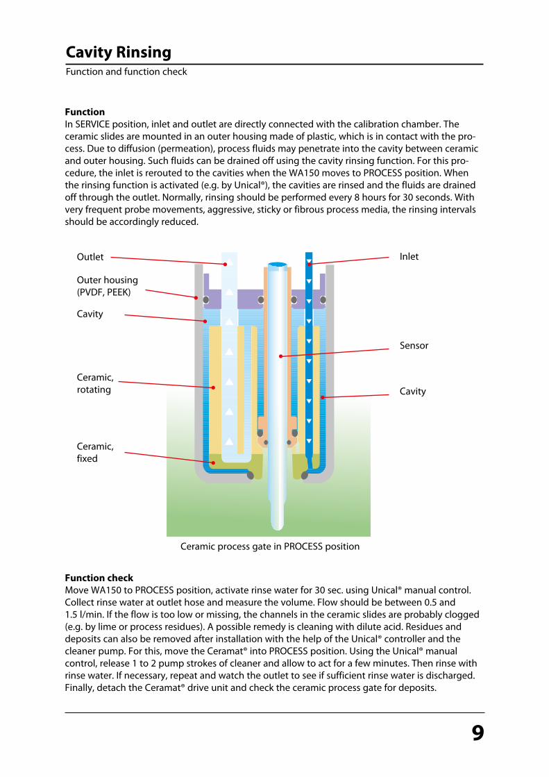
Examine O-rings (statically loaded) on inlet and outlet and replace if required (see fig. below).Select the sealing kits according to “Sealing Kits and Sealing Materials“ on page 18.
Detach and examine O-rings 39x2.5 FKM (gray, coated) and replace if required (see fig.).
After detaching the O-ring 39x2.5, examine the O-ring groove for corrosion or deposits. If neces-sary, remove deposits. If the O-ring groove displays heavier corrosion (e.g. insufficient or missing cavity rinsing, untight ceramic process gate), send in the drive unit for repair to the factory.To continue operating the measuring point without interruption, a loan drive can be supplied on request during the repair works.Replacement of the drive under process pressure in SERVICE position is possible at any time.
Relubricate the O-rings (see “Selection of Suitable Lubricants“ on page 17).
O-ring 39x2.5 FKM coated (order no. #69672)Examine the O-ring groove below for deposits or corrosion.
Inlet
O-ring 5x1.78(Dimensions may differ for FFKM)
O-ring 9.52x1.78(Dimensions may differ for FFKM)
Order no. of O-rings according to “Sealing Kits and Sealing Materials“ on page 18.
Outlet

14
Checking the Process Unit Ceramat® WA 150(X) Sensor Lock-Gate
Check the probe housing for deposits and signs of chemical attack. If deposits are formed in the ceramic aperture over short periods of time, you should use a long sensor socket (ZU 0672 stainless steel or ZU 0673 Hastelloy) (refer to “Accessories“ on page 22).
Probe housing
Ceramic aperture
Check securing ring for corrosion. Relubricate the ceramic apertures circumferen-tially in the sealing area (see figure). See page 17 for lubricant selection.Have defective probe housings or ceramic slides repaired at the factory. If there are heavy deposits in the ceramic area, check the cavity rinsing and, where necessary, reduce the rinsing intervals.
Lubricate the circumference of the holes here!
Securing ring

15
Installing the Drive Unit in the Process UnitCeramat® WA 150(X) Sensor Lock-Gate
Note! Before installing the drive unit in the process unit, check whether the drive unit is in SERVICE position. Only then can the drive unit be inserted sufficiently deep into the process unit so that the thread of the coupling nut can engage.When mounting the drive unit to the process unit, make sure that the guiding grooves of the drive unit engage with the guiding bars of the process unit (see double groove in fig.). After successful alignment, the drive unit can be inserted and the coupling nut screwed until it noticeably stops. Where required, continue to press the drive unit in while screwing the coupling nut to make screwing easier. Hand tighten the coupling nut with the ZU 0648 Ceramat mounting wrench (refer to “Accessories“ on page 21).Now, the sensor can be installed. Use the ZU 0647 Ceramat mounting wrench (19 mm) for this (refer to “Accessories“ on page 21).
Turn the drive unit so that the double bars engage with the double groove!
Mounting wrench (19 mm A/F), ZU 0647
Coupling nut
Ceramat ZU 0648 mounting wrench
Press the drive unit in for easy mounting

16
Maintenance IntervalsCeramat® WA 150(X) Sensor Lock-Gate
Because of the highly variable process conditions (pressure, temperature, chemically aggressive media etc.), general information on necessary maintenance intervals is difficult to provide. If proven experience has been gained from similar points of measurement with regard to materi-als used and their resistance unter process conditions, the maintenance intervals can be adjusted by the customer. If previous experience is positive, parts of the first inspection may be omitted.
The following maintenance intervals are generally recommended by the manufacturer:
Maintenance interval* Operations required
First inspection after a few weeks Move the probe to the PROCESS position and observe the outlet. If the sensor lock-gate is untight, process fluid will leak from the outlet hose. Move the probe to the SERVICE position. Remove the drive unit (no process interrup-tion necessary) and carry out visual checks of the O-rings to check the general suitability of the material used under the present process conditions (refer to “Disconnecting the Drive Unit from the Process Unit“ on page 10 and “Checking / Replacing the O-Rings of the Drive Unit“ on page 11).
After 1-2 years or 30,000 strokes(after successful first inspection and suitabili-ty of all materials used, this time period may be extended.)
Check/replace the dynamically loaded O-ring on the sensor socket, check the statically load-ed O-rings without process interruption (see also “Checking / Replacing the O-Rings of the Drive Unit“ on page 11).Where required, examine the cavity rinsing (see “Cavity Rinsing“ on page 9).If deposits or chemical attacks on the probe housing are suspected (visible in the probe housing after removing the drive unit), check the process unit (see “Checking the Process Unit“ on page 14).
After 10 years or 500,000 strokes Complete maintenance at the factory with replacement of pneumatic sealings, lubricants, and check of all functions, pressure test, leak test
* The intervals are rough recommendations and vary with the individual application.

17
Selection of Suitable LubricantsCeramat® WA 150(X) Sensor Lock-Gate
Note: The Ceramat® is lubricated at the factory with Syntheso Glep1. For hygienic applica-tions (FDA conformity), the sealings in contact with process and rinse media are lubricated with Beruglide L. The sealing kits provided for replacing the O-rings during maintenance (see page 18) include the corresponding lubricant.
Application Pharma / Food Chemistry / Wastewater
Lubricant Beruglide L(silicone-free)FDA-conformingNSF-H1 registered
Paraliq GTE 703(containing silicone)FDA-conforming(USDA H1)
Syntheso Glep 1(silicone-free)
Materials of elas-tomeric gasketsFKM X X X FFKM X X XEPDM X X X

18
Sealing Kits and Sealing MaterialsCeramat® WA 150(X) Sensor Lock-Gate
Caution! Lubricate all O-rings used. Use the lubricants included with the O-ring sealing kit (see “Selection of Suitable Lubricants“ on page 17).
The sealing kits for repair and maintenance are listed in the following table:
Order code(as delivered)
Sealing kit Process-wetted sealings
Rinse-wetted sealings
Order no.(for mainte-nance)
Suitable lubricant(included)
WA150- A SET A FKM FKM ZU 0624 Syntheso Glep 1WA150- B SET B EPDM EPDM ZU 0625 Syntheso Glep 1WA150- C SET C FFKM FKM ZU 0626 Syntheso Glep 1WA150- E SET E EPDM FDA EPDM FDA ZU 0661 Beruglide LWA150- K SET K FFKM FFKM On request Syntheso Glep 1

19
Accessories Overview for Ceramat® WA 150(X)
Accessories Order No.Flange protector DN80, PEEK ZU 0595Flange protector DN80, PVDF ZU 0596Flange protector DN100, PEEK ZU 0597Flange protector DN100, PVDF ZU 0598Standard-media interface ZU 0631Pneumatic manual control valve ZU 0646Sensor mounting wrench, 19 mm ZU 0647Ceramat® mounting wrench ZU 0648Adapter made of PEEK, O-rings FKM ZU 0654/1Adapter made of PEEK, O-rings EPDM ZU 0654/2Adapter made of PEEK, O-rings FFKM ZU 0654/3Adapter made of 1.4571, O-rings FKM ZU 0655/1Adapter made of 1.4571, O-rings EPDM ZU 0655/2Adapter made of 1.4571, O-rings FFKM ZU 0655/3Air supply for pressurized sensors, 0.5 - 4 bars ZU 0670/1Air supply for pressurized sensors, 1 - 7 bar ZU 0670/2Sensor socket PEEK, O-rings FKM ZU 0616Sensor socket PEEK, O-rings EPDM ZU 0617Sensor socket PEEK, O-rings FFKM ZU 0618Sensor socket PEEK, O-rings EPDM FDA ZU 0619Sensor socket PVDF, O-rings FKM ZU 0620Sensor socket PVDF, O-rings EPDM ZU 0621Sensor socket PVDF, O-rings FFKM ZU 0622Sensor socket PVDF, O-rings EPDM FDA ZU 0623Long sensor socket 1.4571, O-rings FKM ZU 0672/ALong sensor socket 1.4571, O-rings EPDM ZU 0672/BLong sensor socket 1.4571, O-rings FFKM ZU 0672/CLong sensor socket Hastelloy, O-rings FKM ZU 0673/ALong sensor socket Hastelloy, O-rings EPDM ZU 0673/BLong sensor socket Hastelloy, O-rings FFKM ZU 0673/CSensor socket PEEK, scraper ring with scraper edge PEEK, O-rings FKM ZU 0705Sensor socket PEEK, scraper ring with scraper edge PEEK, O-rings EPDM ZU 0706Sensor socket PEEK, scraper ring with scraper edge PEEK, O-rings FFKM ZU 0707Sensor socket 1.4571, full sensor protection, O-rings FKM ZU 0808/ASensor socket 1.4571, full sensor protection, O-rings EPDM ZU 0808/BSensor socket 1.4571, full sensor protection, O-rings FFKM ZU 0808/CSensor socket Hastelloy, full sensor protection, O-rings FKM ZU 0820/ASensor socket Hastelloy, full sensor protection, O-rings EPDM ZU 0820/BSensor socket Hastelloy, full sensor protection, O-rings FFKM ZU 0820/C

20
AccessoriesCeramat® WA 150(X)
ZU 0631Standard-media interface Sensor lock-gate connection kit for manual operation (see ZU 0646) or for operation with a PLC
Flange protector Protection for the Ceramat® flange in stainless steel (mat. no.: 1.4571) against aggressive media, O-ring material FFKMFlange protector DN80, PEEK ZU 0595Flange protector DN80, PVDF ZU 0596Flange protector DN100, PEEK ZU 0597Flange protector DN80, PVDF ZU 0598
ZU 0646Pneumatic manual control valve Switch for manual operation (rocker switch to reverse compressed air) on ZU 0631 standard-media interface
O-ring

21
AccessoriesCeramat® WA 150(X)
ZU 0670/1Air supply for pressurized sensors, 0.5 - 4 bars
ZU 0670/2Air supply for pressurized sensors 1 - 7 bars
This module maintains the defined overpressure in the pressure chamber of the sensor.
ZU 0648Ceramat® mounting wrenchServes to disconnect the drive unit or mount it to the process unit via the coupling nut of the drive unit (see also “Cavity Rinsing“ on page 9 and “Checking the Process Unit“ on page 14).
ZU 0647Sensor mounting wrench, 19 mmRequired for safely screwing in the sensor without overloading the Pg 13.5 plastic thread of the sensor head by an excessive torque (caused by an open-end wrench).
Adapter for additional mediumThis adapter allows the introduction of an additional rinse medium beyond the available media connection (media hose).It is mounted between the Ceramat® and the media hose multiplug. The following variants are available:PEEK, O-rings FKM ZU0654/1PEEK, O-rings EPDM ZU0654/2PEEK, O-rings FFKM ZU0654/31.4571, O-rings FKM ZU0655/11.4571, O-rings EPDM ZU0655/21.4571, O-rings FFKM ZU0655/3

22
AccessoriesCeramat® WA 150(X)
Long sensor socket with mounted O-ringsThis sensor socket is recommended for brittle incrustations (e.g. lime). (Hastelloy C22 can be identified by a missing grip recess.)1.4571, O-rings FKM ZU0672/A1.4571, O-rings EPDM ZU0672/B1.4571, O-rings FFKM ZU0672/CHastelloy, O-rings FKM ZU0673/AHastelloy, O-rings EPDM ZU0673/BHastelloy, O-rings FFKM ZU0673/C
Sensor socket, full sensor protection with mounted O-ringsThis sensor socket is recommended for brittle incrustations (e.g. lime). The sensor is also better mechanically protected.(Hastelloy C22 can be identified by a missing grip recess.)1.4571, O-rings FKM ZU0808/A1.4571, O-rings EPDM ZU0808/B1.4571, O-rings FFKM ZU0808/CHastelloy, O-rings FKM ZU0820/AHastelloy, O-rings EPDM ZU0820/BHastelloy, O-rings FFKM ZU0820/C
Sensor socket with mounted O-ringsPEEK, O-rings FKM ZU 0616PEEK, O-rings EPDM ZU 0617PEEK, O-rings FFKM ZU 0618PEEK, O-rings EPDM FDA ZU 0619PVDF, O-rings FKM ZU 0620PVDF, O-rings EPDM ZU 0621PVDF, O-rings FFKM ZU 0622PVDF, O-rings EPDM FDA ZU 0623
Hastelloy identified by a missing grip
Hastelloy identified by a missing grip
Scraper ring with scraper edge
Sensor socket with mounted O-rings and scraper ring with scraper edge made of PEEKThis sensor socket is recommended for sticky media and for particles in the process medium. PEEK, O-rings FKM ZU 0705PEEK, O-rings EPDM ZU 0706PEEK, O-rings FFKM ZU 0707

23
Declaration of ContaminationCeramat® WA 150(X)
Declaration on the potential hazards presented by the enclosed devices/sensors
Knick Elektronische Messgeräte GmbH & Co. KG, Beuckestraße 22, 14163 Berlin Telefon: ++49 (0) 30 8 01 91 – 0 / Telefax: ++49 (0) 30 8 01 91 – 200
Email: [email protected] / Internet: www.knick.de
For acceptance and execution of your order we require this completed declaration form.
Please enclose it with the shipping documents.
Customer data
Company name:
Address:
Contact person: Phone: Device/sensor specifications
Sensor: (Catalog number)
Serial no.
Your order number:
Knick order confirmation no.:
Included accessories:
Reason for return of product:
Warning notices as to the medium in which the device/sensor has been used (please tick where applicable):
harmless harmful/ toxic / corrosive oxidizing / infectious / irritant explosive radioactive
Cleaning measures taken before shipment (cleaning methods and cleaning agents used):
1. 2.
3. 4.
I herewith declare that the shipped parts do not pose any health hazards for employees of Knick
Elektronische Messgeräte GmbH & Co. KG. I further declare that I have answered the questions above
truthfully and to the best of my knowledge. I understand that I may be held liable for any damage resulting from false or incorrect information.
Name: Company:
Date: Signature:

KnickElektronische Messgeräte GmbH & Co. KGBeuckestr. 22D-14163 Berlin
Phone: +49 (0)30 - 801 91 - 0Fax: +49 (0)30 - 801 91 - 200Internet: http://[email protected]
TA-203.001-KNE01 20130426


![sasaki-tekko.comsasaki-tekko.com/images/WA150-5.pdf · Easy operation Ecology Economy R5*fiífifSTARE-HST E-a LOADER fWA150-5]I & Enuipumnent optimization environmenÞLFriend1y—](https://img.dokumen.tips/doc/110x75/5b07183b7f8b9ad5548dce8b/sasaki-tekkocomsasaki-tekkocomimageswa150-5pdfeasy-operation-ecology-economy.jpg)