Embed Size (px)
Citation preview

BA00384P/00/EN/07.14
71270337
Valid from software version:
01.00.zz
Operating Instructions
Cerabar M PMC51, PMP51, PMP55
Deltabar M PMD55
Deltapilot M FMB50/51/52/53
Process pressure / Differential pressure, Flow / Hydrostatic
Deltapilot M
Deltabar M
Cerabar M

Cerabar M, Deltabar M, Deltapilot M/FOUNDATION Fieldbus
2 Endress+Hauser
A0023555
TAG No.: XXX000
Ser. No.: X000X000000
Order code 00X00-XXXX0XX0XXX
www.endress.com/deviceviewer Endress+Hauser Operations App
Serial number

Cerabar M, Deltabar M, Deltapilot M/FOUNDATION Fieldbus Table of contents
Endress+Hauser 3
Table of contents
1 Safety instructions . . . . . . . . . . . . . . . . 4
1.1 Designated use . . . . . . . . . . . . . . . . . . . . . . . . . . . . 4
1.2 Installation, commissioning and operation . . . . . . . . 4
1.3 Operational and process safety . . . . . . . . . . . . . . . . . 4
1.4 Notes on safety conventions and icons . . . . . . . . . . . 5
2 Identification . . . . . . . . . . . . . . . . . . . . 6
2.1 Product identification . . . . . . . . . . . . . . . . . . . . . . . 6
2.2 Device designation . . . . . . . . . . . . . . . . . . . . . . . . . 6
2.3 Scope of delivery . . . . . . . . . . . . . . . . . . . . . . . . . . . 9
2.4 CE mark, Declaration of Conformity . . . . . . . . . . . . 9
2.5 Registered labels . . . . . . . . . . . . . . . . . . . . . . . . . . . 9
3 Installation . . . . . . . . . . . . . . . . . . . . . 10
3.1 Incoming acceptance, transport, storage . . . . . . . . . 10
3.2 Installation conditions . . . . . . . . . . . . . . . . . . . . . . 10
3.3 Installing Cerabar M . . . . . . . . . . . . . . . . . . . . . . . 11
3.4 Installing Deltabar M . . . . . . . . . . . . . . . . . . . . . . 19
3.5 Installing Deltapilot M . . . . . . . . . . . . . . . . . . . . . 27
3.6 Installing profile seal for universal process adapter . 32
3.7 Closing the housing cover . . . . . . . . . . . . . . . . . . . 32
3.8 Post-installation check . . . . . . . . . . . . . . . . . . . . . . 32
4 Wiring . . . . . . . . . . . . . . . . . . . . . . . . 33
4.1 Connecting the device . . . . . . . . . . . . . . . . . . . . . . 33
4.2 Connecting the measuring unit . . . . . . . . . . . . . . . 34
4.3 Potential equalization . . . . . . . . . . . . . . . . . . . . . . 35
4.4 Overvoltage protection (optional) . . . . . . . . . . . . . . 36
4.5 Post-connection check . . . . . . . . . . . . . . . . . . . . . . 37
5 Operation . . . . . . . . . . . . . . . . . . . . . . 38
5.1 Operating options . . . . . . . . . . . . . . . . . . . . . . . . . 38
5.2 Operation without an operating menu . . . . . . . . . 40
5.3 Operation with an operating menu . . . . . . . . . . . . 42
5.4 FOUNDATION Fieldbus communication protocol . 51
6 Commissioning without an operating
menu . . . . . . . . . . . . . . . . . . . . . . . . . 64
6.1 Function check . . . . . . . . . . . . . . . . . . . . . . . . . . . 64
6.2 Position adjustment . . . . . . . . . . . . . . . . . . . . . . . . 64
7 Commissioning with an operating menu
(onsite display/FieldCare) . . . . . . . . . 65
7.1 Function check . . . . . . . . . . . . . . . . . . . . . . . . . . . 65
7.2 Commissioning . . . . . . . . . . . . . . . . . . . . . . . . . . . 65
7.3 Pos. zero adjust . . . . . . . . . . . . . . . . . . . . . . . . . . . 67
7.4 Level measurement (Cerabar M and Deltapilot M) . 68
7.5 Linearization . . . . . . . . . . . . . . . . . . . . . . . . . . . . . 78
7.6 Pressure measurement . . . . . . . . . . . . . . . . . . . . . . 84
7.7 Differential pressure measurement (Deltabar M) . . 85
7.8 Flow measurement (Deltabar M) . . . . . . . . . . . . . . 87
7.9 Level measurement (Deltabar M) . . . . . . . . . . . . . . 90
7.10 Overview of the onsite display operating menu . . . 102
7.11 Description of parameters . . . . . . . . . . . . . . . . . . 110
8 Commissioning with the FF configuration
program. . . . . . . . . . . . . . . . . . . . . . . 131
8.1 Function check . . . . . . . . . . . . . . . . . . . . . . . . . . 131
8.2 Commissioning with FF application . . . . . . . . . . . 131
8.3 Scaling the OUT parameter . . . . . . . . . . . . . . . . . 134
8.4 Commissioning with device application . . . . . . . . 135
8.5 Pos. Zero Adjust . . . . . . . . . . . . . . . . . . . . . . . . . 137
8.6 Pressure measurement . . . . . . . . . . . . . . . . . . . . . 138
8.7 Level measurement . . . . . . . . . . . . . . . . . . . . . . . 139
8.8 Flow measurement (Deltabar M) . . . . . . . . . . . . . 148
8.9 Linearization . . . . . . . . . . . . . . . . . . . . . . . . . . . . 152
8.10 Electrical differential pressure measurement with gauge
pressure sensors (Cerabar M or Deltapilot M) . . . . 154
8.11 Displaying external values on the onsite display via
FF bus . . . . . . . . . . . . . . . . . . . . . . . . . . . . . . . . 156
8.12 Description of parameters . . . . . . . . . . . . . . . . . . 157
9 Maintenance . . . . . . . . . . . . . . . . . . . 210
9.1 Cleaning instructions . . . . . . . . . . . . . . . . . . . . . . 210
9.2 Exterior cleaning . . . . . . . . . . . . . . . . . . . . . . . . . 210
10 Troubleshooting . . . . . . . . . . . . . . . . 211
10.1 Messages . . . . . . . . . . . . . . . . . . . . . . . . . . . . . . . 211
10.2 Response of outputs to errors . . . . . . . . . . . . . . . . 215
10.3 Repair . . . . . . . . . . . . . . . . . . . . . . . . . . . . . . . . . 216
10.4 Repair of Ex-certified devices . . . . . . . . . . . . . . . . 216
10.5 Spare Parts . . . . . . . . . . . . . . . . . . . . . . . . . . . . . 216
10.6 Return . . . . . . . . . . . . . . . . . . . . . . . . . . . . . . . . 216
10.7 Disposal . . . . . . . . . . . . . . . . . . . . . . . . . . . . . . . . 216
10.8 Software history . . . . . . . . . . . . . . . . . . . . . . . . . . 217
11 Technical data . . . . . . . . . . . . . . . . . . 218
Index . . . . . . . . . . . . . . . . . . . . . . . . . . . . . 219
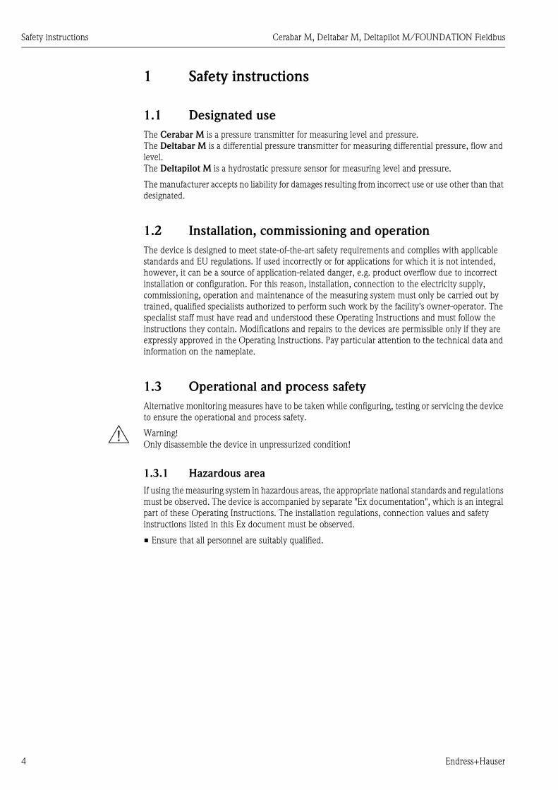
Safety instructions Cerabar M, Deltabar M, Deltapilot M/FOUNDATION Fieldbus
4 Endress+Hauser
1 Safety instructions
1.1 Designated use
The Cerabar M is a pressure transmitter for measuring level and pressure.
The Deltabar M is a differential pressure transmitter for measuring differential pressure, flow and
level.
The Deltapilot M is a hydrostatic pressure sensor for measuring level and pressure.
The manufacturer accepts no liability for damages resulting from incorrect use or use other than that
designated.
1.2 Installation, commissioning and operation
The device is designed to meet state-of-the-art safety requirements and complies with applicable
standards and EU regulations. If used incorrectly or for applications for which it is not intended,
however, it can be a source of application-related danger, e.g. product overflow due to incorrect
installation or configuration. For this reason, installation, connection to the electricity supply,
commissioning, operation and maintenance of the measuring system must only be carried out by
trained, qualified specialists authorized to perform such work by the facility's owner-operator. The
specialist staff must have read and understood these Operating Instructions and must follow the
instructions they contain. Modifications and repairs to the devices are permissible only if they are
expressly approved in the Operating Instructions. Pay particular attention to the technical data and
information on the nameplate.
1.3 Operational and process safety
Alternative monitoring measures have to be taken while configuring, testing or servicing the device
to ensure the operational and process safety.
# Warning!
Only disassemble the device in unpressurized condition!
1.3.1 Hazardous area
If using the measuring system in hazardous areas, the appropriate national standards and regulations
must be observed. The device is accompanied by separate "Ex documentation", which is an integral
part of these Operating Instructions. The installation regulations, connection values and safety
instructions listed in this Ex document must be observed.
• Ensure that all personnel are suitably qualified.

Cerabar M, Deltabar M, Deltapilot M/FOUNDATION Fieldbus Safety instructions
Endress+Hauser 5
1.4 Notes on safety conventions and icons
In order to highlight safety-relevant or alternative operating procedures in the manual, the following
conventions have been used, each indicated by a corresponding icon in the margin.
Symbol Meaning
#Warning!
A warning highlights actions or procedures which, if not performed correctly, will lead to serious
personal injury, a safety hazard or the destruction of the device.
"Caution!
Caution highlights actions or procedures which, if not performed correctly, can lead to personal
injury or the incorrect operation of the device.
!Note!
A note highlights actions or procedures which, if not performed correctly, can have an indirect
effect on operation or trigger an unexpected response on the part of the device.
0Explosion-protected, type-examined equipment
If the device has this symbol embossed on its nameplate, it can be used in a hazardous area or a
non-hazardous area, depending on the approval.
-Hazardous area
This symbol is used in the drawings of these Operating Instructions to indicate hazardous areas.
– Devices used in hazardous areas must possess an appropriate type of protection.
.Safe area (non-hazardous area)
This symbol is used in the drawings of these Operating Instructions to indicate non-hazardous
areas.
– Devices used in hazardous areas must possess an appropriate type of protection. Cables used in
hazardous areas must meet the necessary safety-related characteristic quantities.
% Direct current
A terminal to which DC voltage is applied or through which direct current flows.
&Alternating current
A terminal to which alternating voltage (sine-wave) is applied or through which alternating current
flows.
)Ground connection
A grounded terminal, which as far as the operator is concerned, is already grounded by means of a
grounding system.
* Protective ground connection
A terminal which must be connected to ground prior to establishing any other connections.
+Equipotential connection
A connection that has to be connected to the plant grounding system: This may be a potential
equalization line or a star grounding system depending on national or company codes of practice.
Connecting cable immunity to temperature change
Indicates that the connecting cables have to withstand a temperature of 85°C at least.
Safety instructions
Observe the safety instructions in the associated Operating Instructions.
>=t 85°C

Identification Cerabar M, Deltabar M, Deltapilot M/FOUNDATION Fieldbus
6 Endress+Hauser
2 Identification
2.1 Product identification
The following options are available for identification of the measuring device:
• Nameplate specifications
• Order code with breakdown of the device features on the delivery note
• Enter serial numbers from nameplates in W@M Device Viewer
(www.endress.com/deviceviewer): All information about the measuring device is displayed.
For an overview of the technical documentation provided, enter the serial number from the
nameplates in the W@M Device Viewer (www.endress.com/deviceviewer).
2.2 Device designation
2.2.1 Nameplate
! Note!
• The MWP (maximum working pressure) is specified on the nameplate. This value refers to a
reference temperature of 20°C (68°F) or 100°F (38 °C) for ANSI flanges.
• The pressure values permitted at higher temperatures can be found in the following standards:
– EN 1092-1: 2001 Tab. 18 1)
– ASME B 16.5a – 1998 Tab. 2-2.2 F316
– ASME B 16.5a – 1998 Tab. 2.3.8 N10276
– JIS B 2220
• The test pressure corresponds to the over pressure limit (OPL) of the device = MWP x 1.5 2).
• The Pressure Equipment Directive (EC Directive 97/23/EC) uses the abbreviation "PS". The
abbreviation "PS" corresponds to the MWP (maximum working pressure) of the measuring
device.
1) With regard to their stability-temperature property, the materials 1.4435 and 1.4404 are grouped together under 13EO
in EN 1092-1 Tab. 18. The chemical composition of the two materials can be identical.
2) The equation does not apply for PMP51 and PMP55 with a 40 bar (600 psi) or a 100 bar (1500 psi) measuring cell.

Cerabar M, Deltabar M, Deltapilot M/FOUNDATION Fieldbus Identification
Endress+Hauser 7
Aluminum housing
P01-xMx5xxxx-18-xx-xx-xx-000
Fig. 1: Nameplate
1 Device name
2 Order code (for re-orders)
3 Serial number (for identification)
4 Extended order code (complete)
5 MWP (maximum working pressure)
6 Electronic version (output signal)
7 Min./max. span
8 Nominal measuring range
9 Supply voltage
10 Unit of length
11 ID number of notified body with regard to ATEX (optional)
12 ID number of notified body with regard to Pressure Equipment Directive (optional)
13 Approvals
14 Device version
15 Software version
16 Degree of protection
17 Wetted materials
18 Approval-specific information
Devices suitable for oxygen applications are fitted with an additional nameplate.
P01-xxxxxxxx-18-xx-xx-xx-000
Fig. 2: Additional nameplate for devices suitable for oxygen applications
1 Maximum pressure for oxygen applications
2 Maximum temperature for oxygen applications
3 Layout identification of the nameplate
ex works FW:
Dev.Rev.:
25
00
02
75
5-C
Ext. order code:Ser. no.:
U=Span
P
MWP
Order code:
Made in Germany, D-79689 Maulburg Mat.:
25
00
02
75
6-EL=
15
12 3
46 7
8 9 10
1112
1314
5
16
17
18
18
PmaxTmax
for oxygen serviceBei Sauerstoffeinsatz/
312
Identification Cerabar M, Deltabar M, Deltapilot M/FOUNDATION Fieldbus
8 Endress+Hauser
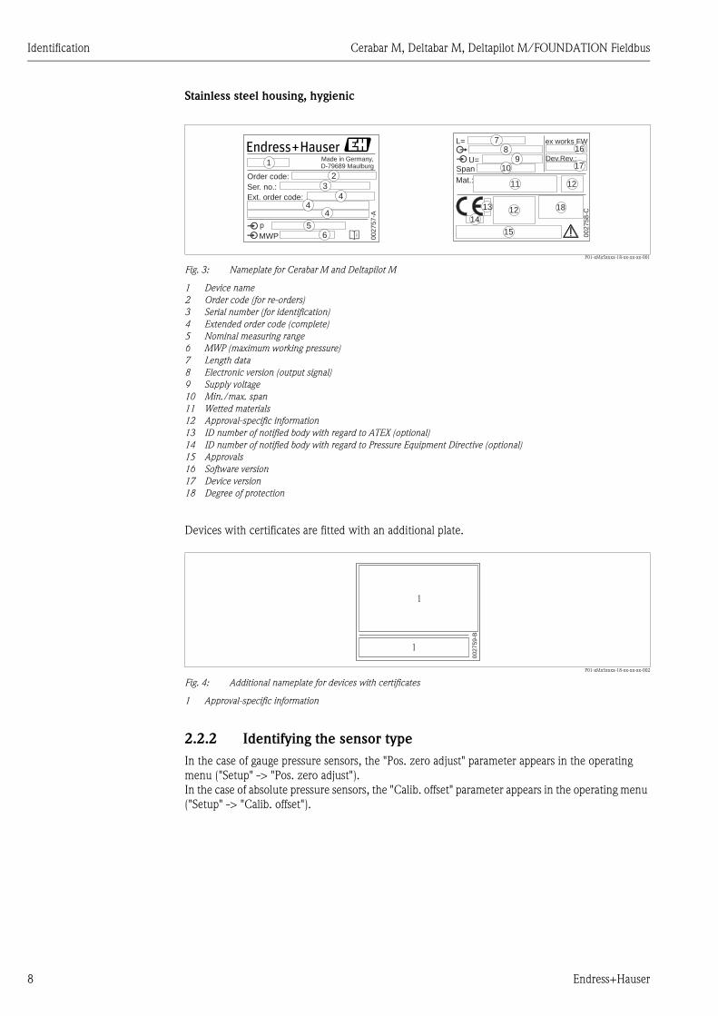
Stainless steel housing, hygienic
P01-xMx5xxxx-18-xx-xx-xx-001
Fig. 3: Nameplate for Cerabar M and Deltapilot M
1 Device name
2 Order code (for re-orders)
3 Serial number (for identification)
4 Extended order code (complete)
5 Nominal measuring range
6 MWP (maximum working pressure)
7 Length data
8 Electronic version (output signal)
9 Supply voltage
10 Min./max. span
11 Wetted materials
12 Approval-specific information
13 ID number of notified body with regard to ATEX (optional)
14 ID number of notified body with regard to Pressure Equipment Directive (optional)
15 Approvals
16 Software version
17 Device version
18 Degree of protection
Devices with certificates are fitted with an additional plate.
P01-xMx5xxxx-18-xx-xx-xx-002
Fig. 4: Additional nameplate for devices with certificates
1 Approval-specific information
2.2.2 Identifying the sensor type
In the case of gauge pressure sensors, the "Pos. zero adjust" parameter appears in the operating
menu ("Setup" -> "Pos. zero adjust").
In the case of absolute pressure sensors, the "Calib. offset" parameter appears in the operating menu
("Setup" -> "Calib. offset").
00
27
57
-A
p
Order code:
Ext. order code:
Ser. no.:
MWP
D-79689 MaulburgMade in Germany,
ex works FW
U= Dev.Rev.:
L=
Span
Mat.:
00
27
58
-C
16
17
15
1
23
44
4
6
78
910
11
12
12
13
145
18
00
27
59
-B
1
1
Cerabar M, Deltabar M, Deltapilot M/FOUNDATION Fieldbus Identification
Endress+Hauser 9
2.3 Scope of delivery
The scope of delivery comprises:
• Device
• Optional accessories
Documentation supplied:
• The Operating Instructions BA00384P is available on the Internet.
See: www.endress.com Download
• Brief Operating Instructions: KA01032P Cerabar M / KA01029P Deltabar M / KA01035P
Deltapilot M
• Final inspection report
• Additional Safety Instructions for ATEX, IECEx and NEPSI devices
• Optional: factory calibration form, test certificates
2.4 CE mark, Declaration of Conformity
The devices are designed to meet state-of-the-art safety requirements, have been tested and left the
factory in a condition in which they are safe to operate. The devices comply with the applicable
standards and regulations as listed in the EC Declaration of Conformity and thus comply with the
statutory requirements of the EC Directives. Endress+Hauser confirms the conformity of the device
by affixing to it the CE mark.
2.5 Registered labels
KALREZ, VITON, TEFLON
Registered label of E.I. Du Pont de Nemours & Co., Wilmington, USA
TRI-CLAMP
Registered label of Ladish & Co., Inc., Kenosha, USA
FOUNDATIONTM Fieldbus
Registered trademark of the Fieldbus Foundation Austin, Texas, USA
GORE-TEX®
Registered label of W.L. Gore & Associates, Inc., USA

Installation Cerabar M, Deltabar M, Deltapilot M/FOUNDATION Fieldbus
10 Endress+Hauser
3 Installation
3.1 Incoming acceptance, transport, storage
3.1.1 Incoming acceptance
• Check the packaging and the contents for damage.
• Check the shipment, make sure nothing is missing and that the scope of supply matches your
order.
3.1.2 Transport
" Caution!
Follow the safety instructions and transport conditions for devices of more than 18 kg (39.69 lbs).
Transport the measuring device to the measuring point in its original packaging or at the process
connection.
3.1.3 Storage
The device must be stored in a dry, clean area and protected against damage from impact
(EN 837-2).
Storage temperature range:
See Technical Information for Cerabar M TI00436P / Deltabar M TI00434P / Deltapilot M
TI00437P.
3.2 Installation conditions
3.2.1 Dimensions
For dimensions, please refer to the Technical Information for Cerabar M TI00436P / Deltabar
M TI00434P / Deltapilot M TI00437P, "Mechanical construction" section.

Cerabar M, Deltabar M, Deltapilot M/FOUNDATION Fieldbus Installation
Endress+Hauser 11
3.3 Installing Cerabar M
! Note!
• Due to the orientation of the Cerabar M, there may be a shift in the zero point, i.e. when the
container is empty or partially full, the measured value does not display zero. You can correct this
zero point shift ä 41, Section "Function of the operating elements" or ä 67, Section 7.3
"Pos. zero adjust".
• For PMP55, please refer to Section 3.3.2 "Installation instructions for devices with diaphragm
seals – PMP55", ä 14.
• Endress+Hauser offers a mounting bracket for installing on pipes or walls.
ä 16, Section 3.3.5 "Wall- and pipe-mounting (optional)".
3.3.1 Installation instructions for devices without diaphragm seals –
PMP51, PMC51
! Note!
• If a heated Cerabar M is cooled during the cleaning process (e.g. by cold water), a vacuum
develops for a short time, whereby moisture can penetrate the sensor through the pressure
compensation (1). If this is the case, mount the Cerabar M with the pressure compensation (1)
pointing downwards.
• Keep the pressure compensation and GORE-TEX® filter (1) free from contamination.
• Cerabar M transmitters without diaphragm seals are mounted as per the norms for a manometer
(DIN EN 837-2). We recommend the use of shutoff devices and siphons. The orientation depends
on the measuring application.
• Do not clean or touch process isolating diaphragms with hard or pointed objects.
• The device must be installed as follows in order to comply with the cleanability requirements of
the ASME-BPE (Part SD Cleanibility).:
1
1
1

Installation Cerabar M, Deltabar M, Deltapilot M/FOUNDATION Fieldbus
12 Endress+Hauser
Pressure measurement in gases
P01-PMx5xxxx-11-xx-xx-xx-003
Fig. 5: Measuring arrangement for pressure measurement in gases
1 Cerabar M
2 Shutoff device
• Mount Cerabar M with shutoff device above the tapping point so that condensate which may be
present can flow into the process.
Pressure measurement in steams
P01-PMx5xxxx-11-xx-xx-xx-004
Fig. 6: Measuring arrangement for pressure measurement in steams
1 Cerabar M
2 Shutoff device
3 U-shaped siphon
4 Circular siphon
• Mount Cerabar M with siphon above the tapping point.
• Fill the siphon with liquid before commissioning.
The siphon reduces the temperature to almost the ambient temperature.
➁
➀
➂
➀
➁
➃
➀
➁

Cerabar M, Deltabar M, Deltapilot M/FOUNDATION Fieldbus Installation
Endress+Hauser 13
Pressure measurement in liquids
P01-PMx5xxxx-11-xx-xx-xx-005
Fig. 7: Measuring arrangement for pressure measurement in liquids
1 Cerabar M
2 Shutoff device
• Mount Cerabar M with shutoff device below or at the same level as the tapping point.
Level measurement
P01-xMx5xxxx-11-xx-xx-xx-000
Fig. 8: Measuring arrangement for level
• Always install the Cerabar M below the lowest measuring point.
• Do not mount the device in the filling curtain or at a point in the tank which could be affected by
pressure pulses from an agitator.
• Do not mount the device in the suction area of a pump.
• The calibration and functional test can be carried out more easily if you mount the device
downstream of a shutoff device.
PVDF interchangeable threaded boss
! Note!
A maximum torque of 7 Nm (5.16 lbs ft) is permitted for devices with a PVDF interchangeable
threaded boss. The thread connection may become loose at high temperatures and pressures. This
means that the integrity of the thread must be checked regularly and may need to be tightened using
the torque given above. Teflon tape is recommended for sealing the 1/2 NPT thread.
➁
➀
Installation Cerabar M, Deltabar M, Deltapilot M/FOUNDATION Fieldbus
14 Endress+Hauser
3.3.2 Installation instructions for devices with diaphragm seals –
PMP55
! Note!
• Cerabar M devices with diaphragm seals are screwed in, flanged or clamped, depending on the
type of diaphragm seal.
• A diaphragm seal and the pressure transmitter together form a closed, oil-filled calibrated system.
The fill fluid hole is sealed and may not be opened.
• Do not clean or touch the process isolating diaphragm of the diaphragm seal with hard or pointed
objects.
• Do not remove process isolating diaphragm protection until shortly before installation.
• When using a mounting bracket, sufficient strain relief must be ensured for the capillaries in order
to prevent the capillary bending down (bending radius 100 mm (3.94 in)).
• Please note that the hydrostatic pressure of the liquid columns in the capillaries can cause zero
point shift. The zero point shift can be corrected. ä 67, Section 7.3 "Pos. zero adjust".
• Please observe the application limits of the diaphragm seal filling oil as detailed in the Technical
Information for Cerabar M TI00436P, "Planning instructions for diaphragm seal systems" section.
In order to obtain more precise measurement results and to avoid a defect in the device, mount the
capillaries as follows:
• Vibration-free (in order to avoid additional pressure fluctuations)
• Not in the vicinity of heating or cooling lines
• Insulate if the ambient temperature is below or above the reference temperature
• With a bending radius of 100 mm (3.94 in).
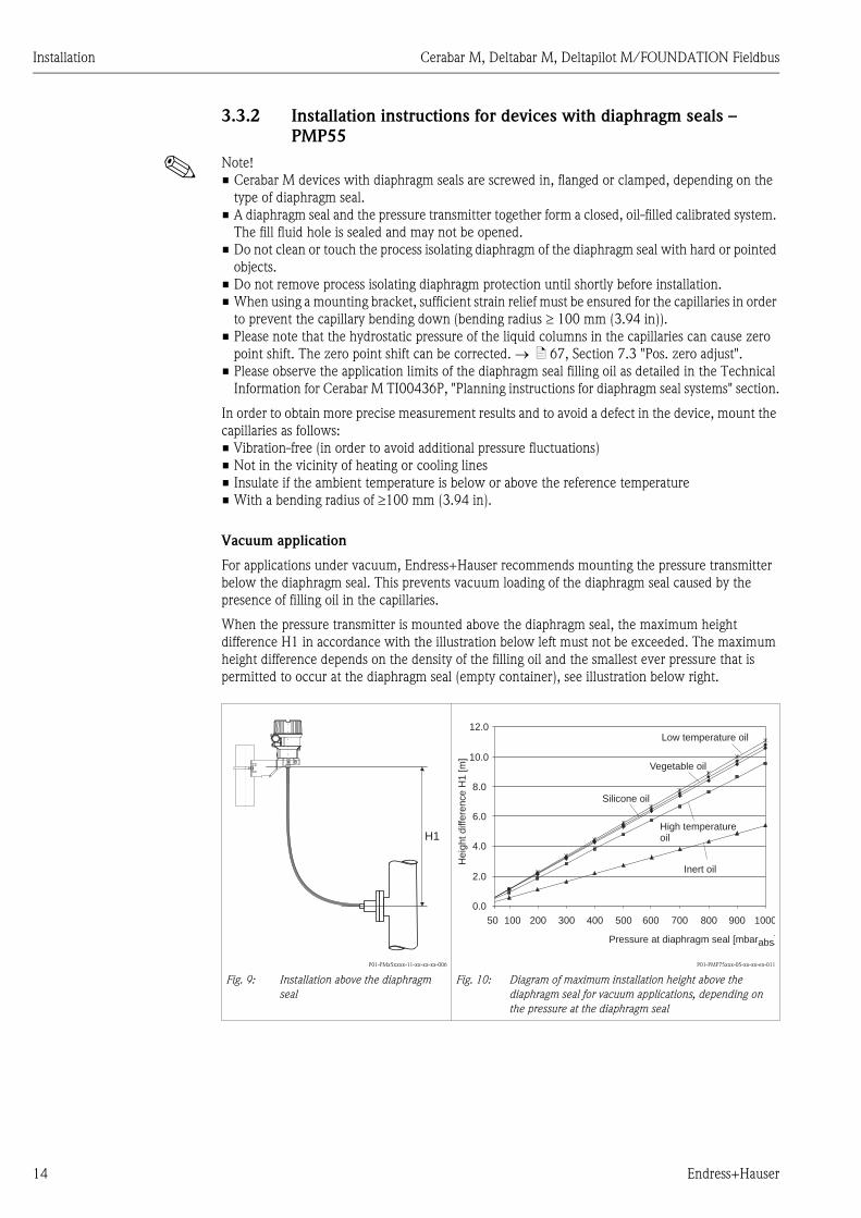
Vacuum application
For applications under vacuum, Endress+Hauser recommends mounting the pressure transmitter
below the diaphragm seal. This prevents vacuum loading of the diaphragm seal caused by the
presence of filling oil in the capillaries.
When the pressure transmitter is mounted above the diaphragm seal, the maximum height
difference H1 in accordance with the illustration below left must not be exceeded. The maximum
height difference depends on the density of the filling oil and the smallest ever pressure that is
permitted to occur at the diaphragm seal (empty container), see illustration below right.
P01-PMx5xxxx-11-xx-xx-xx-006
Fig. 9: Installation above the diaphragm
seal
P01-PMP75xxx-05-xx-xx-en-011
Fig. 10: Diagram of maximum installation height above the
diaphragm seal for vacuum applications, depending on
the pressure at the diaphragm seal
H1
0.0
2.0
4.0
6.0
8.0
10.0
12.0
50 100 300 400 500 600 700 800 900 1000200
Inert oil
High temperatureoil
Vegetable oil
Silicone oil
Pressure at diaphragm seal [mbarabs]
He
igh
td
iffe
ren
ce
H1
[m]
Low temperature oil

Cerabar M, Deltabar M, Deltapilot M/FOUNDATION Fieldbus Installation
Endress+Hauser 15
Mounting with temperature isolator
P01-PMx5xxxx-11-xx-xx-xx-008
Endress+Hauser recommends the use of temperature isolators in the event of constant extreme
medium temperatures which lead to the maximum permissible electronics temperature of +85°C
(+185°F) being exceeded. To minimize the influence of rising heat, Endress+Hauser recommends
the device be mounted horizontally or with the housing pointing downwards.
The additional installation height also brings about a zero point shift of approx. 21 mbar (0.315 psi)
due to the hydrostatic column in the temperature isolator. You can correct this zero point shift.
ä 41 "Function of the operating elements" or ä 67, Section 7.3 "Pos. zero adjust".
3.3.3 Seal for flange mounting
P01-FMD7xxxx-11-xx-xx-xx-002
Fig. 11: Mounting the versions with a flange
1 Process isolating diaphragm
2 Seal
# Warning!
The seal is not allowed to press against the process isolating diaphragm as this could affect the
measurement result.
max. 115
➁➀

Installation Cerabar M, Deltabar M, Deltapilot M/FOUNDATION Fieldbus
16 Endress+Hauser
3.3.4 Thermal insulation – PMP55
The PMP55 may only be insulated up to a certain height. The maximum permitted insulation height
is indicated on the devices and applies to an insulation material with a heat conductivity 0.04 W/
(m x K) and to the maximum permitted ambient and process temperature ( see table below). The
data were determined under the most critical application "quiescent air".
P01-PMx5xxxx-11-xx-xx-xx-010
Fig. 12: Maximum permitted insulation height, here indicated on a PMP55 with a flange
3.3.5 Wall- and pipe-mounting (optional)
Endress+Hauser offers a mounting bracket for installing on pipes or walls (for pipes with diameters
of 1 ¼" to 2").
P01-xMx5xxxx-06-xx-xx-xx-001
Please note the following when mounting:
• Devices with capillary tubes: mount capillaries with a bending radius 100 mm (3.94 in).
• In the case of pipe mounting, the nuts on the bracket must be tightened uniformly with a torque
of at least 5 Nm (3.69 lbs ft).
� 0.04� Wm K•
TP
TA
PMP55
Ambient temperature (TA) 70°C (158°F)
Process temperature (TP) max. 400°C (752°F), depending on the diaphragm seal filling oil used (see TI00436PEN)
52 (
2.05
)
140 (
5.5
1)
122 (
4.8
)
70 (2.76)
6 (0.24)
mm (in)

Cerabar M, Deltabar M, Deltapilot M/FOUNDATION Fieldbus Installation
Endress+Hauser 17
3.3.6 Assembling and mounting the "separate housing" version
P01-XMx5xxxx-11-xx-xx-xx-009
Fig. 13: "Separate housing" version
1 In the case of the "separate housing" version, the sensor is delivered with the process connection and cable ready
mounted.
2 Cable with connection jack
3 Pressure compensation
4 Connector
5 Locking screw
6 Housing mounted with housing adapter, included
7 Mounting bracket suitable for wall- and pipe-mounting, included (for pipes with diameters of 1 ¼" to 2")
Assembly and mounting
1. Insert the connector (item 4) into the corresponding connection jack of the cable (item 2).
2. Plug the cable into the housing adapter (item 6).
3. Tighten the locking screw (item 5).
4. Mount the housing on a wall or pipe using the mounting bracket (item 7).
In the case of pipe mounting, the nuts on the bracket must be tightened uniformly with a
torque of at least 5 Nm (3.69 lbs ft).
Mount the cable with a bending radius (r) 120 mm (4.72 in).
r � 120 mm1
2
34
5
6
7
7

Installation Cerabar M, Deltabar M, Deltapilot M/FOUNDATION Fieldbus
18 Endress+Hauser
3.3.7 PMP51, version prepared for diaphragm seal mount –
welding recommendation and information on filling
P01-PMP71xxx-11-xx-xx-xx-000
Fig. 14: Version XSJ: prepared for diaphragm seal mount
1 Hole for fill fluid
2 Bearing
3 Setscrew
A1 See the "Welding recommendation" table below
Welding recommendation
Endress+Hauser recommends welding on the diaphragm seal as follows for the "XSJ - prepared for
diaphragm seal mount" version in feature 110 "Process connection" in the order code up to, and
including, 40 bar sensors (600 psi): the total welding depth of the fillet weld is 1 mm (0.04 in) with
an outer diameter of 16 mm (0.63 in). Welding is performed according to the WIG method.
Information on filling
The diaphragm seal must be filled as soon as it has been welded on.
• After welding into the process connection, the sensor assembly must be properly filled with a
filling oil and sealed gas-tight with a sealing ball and lock screw.
Once the diaphragm seal has been filled, the device display should not exceed 10% of the full scale
value of the cell measuring range at the zero point. The internal pressure of the diaphragm seal
must be corrected accordingly.
• Adjustment / calibration:
– The device is operational once it has been fully assembled.
– Once the device has been switched on, the total reset code (7864) must be entered in the path:
"Expert" "System" "Management" Enter reset code (124) (see also Section 5.3.7). The
electronics then read all the specific sensor data out of the sensor electronics. The device then
has to be calibrated to the process measuring range as explained in the Operating Instructions.
ø2.5 (0.1)
5 (0
.2)
➀ ➂➁
ø7.95 (0.31)
A1
mm (in)
Consecutive
seam no.
Sketch/welding groove
shape, dimension as per
DIN 8551
Base material
matching
Welding
process
DIN EN
ISO 24063
Welding
position
Inert gas,
additives
A1
for sensors
40 bar
(600 psi)
P01-PMP71xxx-11-xx-xx-xx-001
Adapter made of
1.4435 (AISI 316L) to
be welded to
diaphragm seal made of
1.4435 or 1.4404
(AISI 316L)
141 PB Inert gas
Ar/H 95/5
Additive:
1.4430
(ER 316L Si)
s1 a0.8

Cerabar M, Deltabar M, Deltapilot M/FOUNDATION Fieldbus Installation
Endress+Hauser 19
3.4 Installing Deltabar M
! Note!
Disassembly of the screws with item number (1) is not permissible under any circumstances and
will result in loss of warranty.
3.4.1 Installation position
! Note!
• Due to the orientation of the Deltabar M, there may be a shift in the measured value, i.e. when
the container is empty, the measured value does not display zero. You may correct this zero point
shift by a position adjustment in one of the following ways:
– via the operation key on the electronics module ( ä 41, "Function of the operating
elements")
– via the operating menu ( ä 67, "Pos. zero adjust")
• General recommendations for routing the impulse piping can be found in DIN 19210 "Methods
for measurement of fluid flow; differential piping for flow measurement devices" or the
corresponding national or international standards.
• Using a three-valve or five-valve manifold allows for easy commissioning, installation and
maintenance without interrupting the process.
• When routing the impulse piping outdoors, ensure that sufficient anti-freeze protection is used,
e.g. by using pipe heat tracing.
• Install the impulse piping with a monotonic gradient of at least 10%.
• Endress+Hauser offers a mounting bracket for installing on pipes or walls ( ä 25, "Wall- and
pipe-mounting (optional)").
Installation position for flow measurement
! Note!
For more information about differential pressure flow measurement refer to following documents:
• Differential pressure flow measurement with orifices: Technical Information TI00422P
• Differential pressure flow measurement with Pitot tubes: Technical Information TI00425P
1

Installation Cerabar M, Deltabar M, Deltapilot M/FOUNDATION Fieldbus
20 Endress+Hauser
Flow measurement in gases
P01-PMD55xxx-11-xx-xx-xx-000
Measuring layout for flow measurement in gases
1 Deltabar M
2 Three-valve manifold
3 Shut-off valves
4 Orifice plate or pitot tube
• Mount the Deltabar M above the measuring point so that the condensate which may be present,
can run off into the process piping.
Flow measurement in steam
P01-PMD55xxx-11-xx-xx-xx-001
Measuring layout for flow measurement in steam
1 Condensate traps
2 Orifice plate or pitot tube
3 Shut-off valves
4 Deltabar M
5 Separator
6 Drain valves
7 Three-valve manifold
• Mount the Deltabar M below the measuring point.
• Mount the condensate traps at the same level as the tapping points and at the same distance to
the Deltabar M.
• Prior to commissioning, fill the impulse piping to the height of the condensate traps.
➀
➂
➃+ –
➁
➀
➁
➃+ –➂
➅
➄
➆
➂
➅
➄

Cerabar M, Deltabar M, Deltapilot M/FOUNDATION Fieldbus Installation
Endress+Hauser 21
Flow measurement in liquids
P01-PMD55xxx-11-xx-xx-xx-002
Measuring layout for flow measurement in liquids
1 Orifice plate or pitot tube
2 Shut-off valves
3 Deltabar M
4 Separator
5 Drain valves
6 Three-valve manifold
• Mount the Deltabar M below the measuring point so that the impulse piping is always filled with
liquid and gas bubbles can run back into the process piping.
• When measuring in media with solid parts, such as dirty liquids, installing separators and drain
valves is useful for capturing and removing sediment.
+ –
➀
➂
➅
➁
➃
➄
➁
➃
➄
Installation Cerabar M, Deltabar M, Deltapilot M/FOUNDATION Fieldbus
22 Endress+Hauser
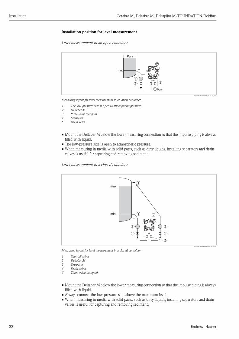
Installation position for level measurement
Level measurement in an open container
P01-PMD55xxx-11-xx-xx-xx-003
Measuring layout for level measurement in an open container
1 The low-pressure side is open to atmospheric pressure
2 Deltabar M
3 three-valve manifold
4 Separator
5 Drain valve
• Mount the Deltabar M below the lower measuring connection so that the impulse piping is always
filled with liquid.
• The low-pressure side is open to atmospheric pressure.
• When measuring in media with solid parts, such as dirty liquids, installing separators and drain
valves is useful for capturing and removing sediment.
Level measurement in a closed container
P01-PMD55xxx-11-xx-xx-xx-004
Measuring layout for level measurement in a closed container
1 Shut-off valves
2 Deltabar M
3 Separator
4 Drain valves
5 Three-valve manifold
• Mount the Deltabar M below the lower measuring connection so that the impulse piping is always
filled with liquid.
• Always connect the low-pressure side above the maximum level.
• When measuring in media with solid parts, such as dirty liquids, installing separators and drain
valves is useful for capturing and removing sediment.
+
➃➂
➀
➁
➄
patm
min.
patm
+
– ➀
➂
➃
➄
➁➀
➂
➃
min.
max.

Cerabar M, Deltabar M, Deltapilot M/FOUNDATION Fieldbus Installation
Endress+Hauser 23
Level measurement in a closed container with superimposed steam
P01-PMD55xxx-11-xx-xx-xx-005
Measuring layout for level measurement in a container with superimposed steam
1 Condensate trap
2 Shut-off valves
3 Deltabar M
4 Separator
5 Drain valves
6 Three-valve manifold
• Mount the Deltabar M below the lower measuring connection so that the impulse piping is always
filled with liquid.
• Always connect the low-pressure side above the maximum level.
• A condensate trap ensures constant pressure on the low-pressure side.
• When measuring in media with solid parts, such as dirty liquids, installing separators and drain
valves is useful for capturing and removing sediment.
+
–
➂
➀
➁
➃
➄
➅
➃
➄
min.
max.
➁
Installation Cerabar M, Deltabar M, Deltapilot M/FOUNDATION Fieldbus
24 Endress+Hauser
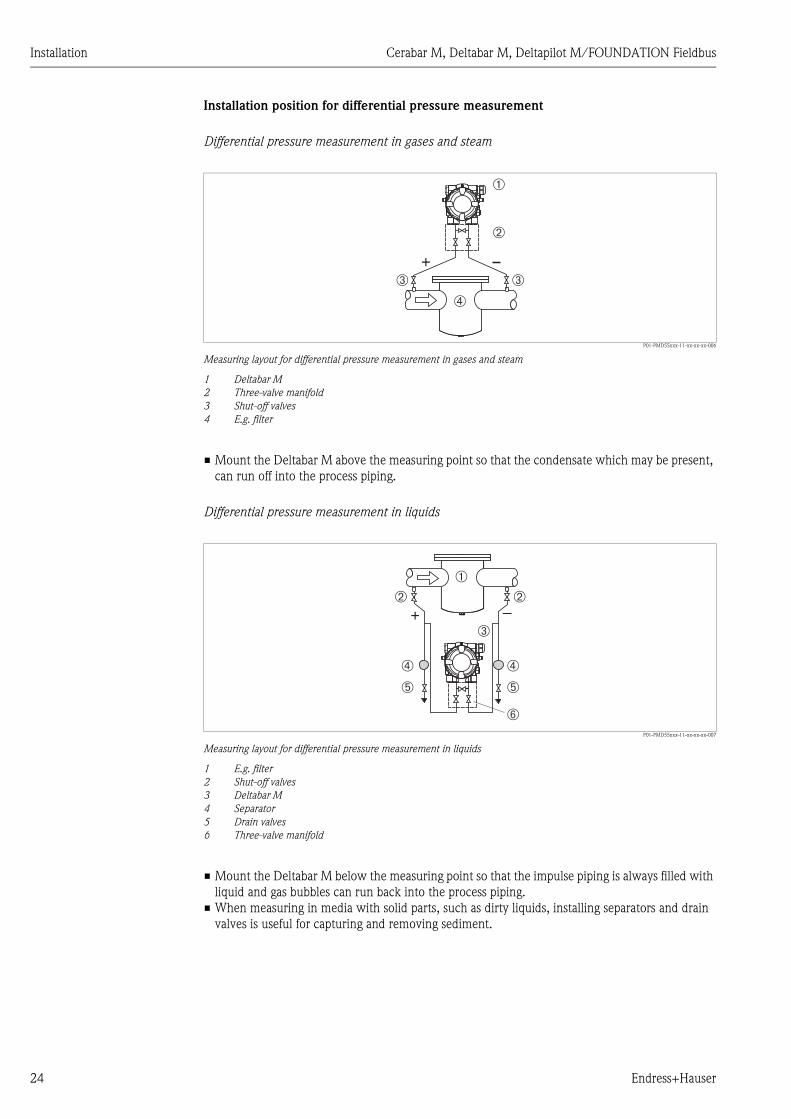
Installation position for differential pressure measurement
Differential pressure measurement in gases and steam
P01-PMD55xxx-11-xx-xx-xx-006
Measuring layout for differential pressure measurement in gases and steam
1 Deltabar M
2 Three-valve manifold
3 Shut-off valves
4 E.g. filter
• Mount the Deltabar M above the measuring point so that the condensate which may be present,
can run off into the process piping.
Differential pressure measurement in liquids
P01-PMD55xxx-11-xx-xx-xx-007
Measuring layout for differential pressure measurement in liquids
1 E.g. filter
2 Shut-off valves
3 Deltabar M
4 Separator
5 Drain valves
6 Three-valve manifold
• Mount the Deltabar M below the measuring point so that the impulse piping is always filled with
liquid and gas bubbles can run back into the process piping.
• When measuring in media with solid parts, such as dirty liquids, installing separators and drain
valves is useful for capturing and removing sediment.
+➂
➀
➁
➂
➃
+ –➂
➅
➁ ➁
➄
➃
➄
➃
➀

Cerabar M, Deltabar M, Deltapilot M/FOUNDATION Fieldbus Installation
Endress+Hauser 25
3.4.2 Wall- and pipe-mounting (optional)
Endress+Hauser offers a mounting bracket for installing the device on pipes or walls. A bracket with
mounting accessories is included with the device if ordered.
! Note!
When using a valve block, the block's dimensions must be taken into account.
P01-PMD55xxx-06-xx-xx-xx-004
Mounting bracket for wall- and pipe-mounting
1 Adaption plate (+ six screws and six washers)
2 Mounting bracket (+ bracket for pipe mounting and two nuts)
Please note the following when mounting:
• To prevent the mounting screws from scoring, lubricate them with a multi-purpose grease prior
to mounting.
• In the case of pipe mounting, the nuts on the bracket must be tightened uniformly with a torque
of at least 30 Nm (22.13 lbf ft).
• For installation purposes, only use the screws with item number (2) (see the following diagram).
2
1
41
.3
90
66.4
546
0
30
66.4
M10
7/16
1067474124
13
5
37
.5
54
54
41
.3
41.3

Installation Cerabar M, Deltabar M, Deltapilot M/FOUNDATION Fieldbus
26 Endress+Hauser
! Note!
Installation of the mounting bracket at the screws with item number (1) is not permissible and will
result in loss of warranty.
Typical installation arrangements
A0023109
A: Impulse line vertical, version V1, alignment 90°
B: Impulse line horizontal, version H1, alignment 180°
C: Impulse line horizontal, version H2, alignment 90°
1: Deltabar M; 2: Adapter; 3: Mounting bracket
2
2
1
1
3
2
1
1
2
3
4
4
CA B
4

Cerabar M, Deltabar M, Deltapilot M/FOUNDATION Fieldbus Installation
Endress+Hauser 27
3.5 Installing Deltapilot M
! Note!
• Due to the orientation of the Deltapilot M, there may be a shift in the zero point, i.e. when the
container is empty or partially full, the measured value does not display zero. You can correct this
zero point shift ä 41, Section "Function of the operating elements" or ä 67, Section 7.3
"Pos. zero adjust".
• The onsite display can be rotated in 90° stages.
• Endress+Hauser offers a mounting bracket for installing on pipes or walls.
ä 16, Section 3.3.5 "Wall- and pipe-mounting (optional)".
3.5.1 General installation instructions
! Note!
• Do not clean or touch process isolating diaphragms with hard or pointed objects.
• The process isolating diaphragm in the rod and cable version is protected against mechanical
damage by a plastic cap.
• If a heated Deltapilot M is cooled during the cleaning process (e.g. by cold water), a vacuum
develops for a short time, whereby moisture can penetrate the sensor through the pressure
compensation (1). If this is the case, mount the Deltapilot M with the pressure compensation (1)
pointing downwards.
• Keep the pressure compensation and GORE-TEX® filter (1) free from contamination.
• To comply with ASME-BPE requirements regarding cleanability (Part SD Cleanability), the device
must be installed as follows:
1
1
1
Installation Cerabar M, Deltabar M, Deltapilot M/FOUNDATION Fieldbus
28 Endress+Hauser
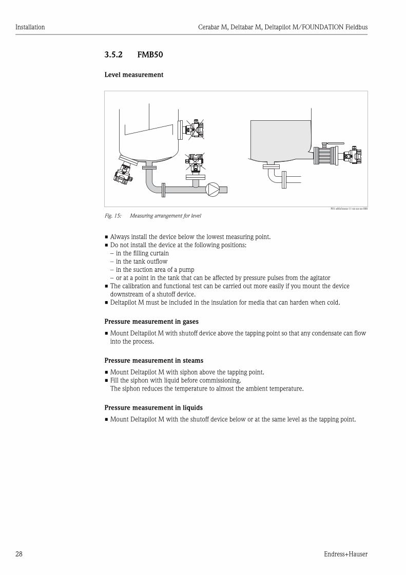
3.5.2 FMB50
Level measurement
P01-xMx5xxxx-11-xx-xx-xx-000
Fig. 15: Measuring arrangement for level
• Always install the device below the lowest measuring point.
• Do not install the device at the following positions:
– in the filling curtain
– in the tank outflow
– in the suction area of a pump
– or at a point in the tank that can be affected by pressure pulses from the agitator
• The calibration and functional test can be carried out more easily if you mount the device
downstream of a shutoff device.
• Deltapilot M must be included in the insulation for media that can harden when cold.
Pressure measurement in gases
• Mount Deltapilot M with shutoff device above the tapping point so that any condensate can flow
into the process.
Pressure measurement in steams
• Mount Deltapilot M with siphon above the tapping point.
• Fill the siphon with liquid before commissioning.
The siphon reduces the temperature to almost the ambient temperature.
Pressure measurement in liquids
• Mount Deltapilot M with the shutoff device below or at the same level as the tapping point.

Cerabar M, Deltabar M, Deltapilot M/FOUNDATION Fieldbus Installation
Endress+Hauser 29
3.5.3 FMB51/FMB52/FMB53
• When mounting rod and cable versions, make sure that the probe head is located at a point as
free as possible from flow. To protect the probe from impact resulting from lateral movement,
mount the probe in a guide tube (preferably made of plastic) or secure it with a clamping fixture.
• In the case of devices for hazardous areas, comply strictly with the safety instructions when the
housing cover is open.
• The length of the extension cable or the probe rod is based on the planned level zero point. The
height of the protective cap must be taken into consideration when designing the layout of the
measuring point. The level zero point (E) corresponds to the position of the process isolating
diaphragm.
Level zero point = E; top of the probe = L.
3.5.4 Mounting the FMB53 with a mounting clamp
P01-FMX21xxx-17-xx-xx-xx-004
Fig. 16: Mounting with a mounting clamp
1 Extension cable
2 Mounting clamp
3 Clamping jaws
Mounting the mounting clamp:
1. Mount the mounting clamp (item 2). When selecting the place to fix the unit, take the weight
of the extension cable (item 1) and the device into account.
2. Raise the clamping jaws (item 3). Position the extension cable (item 1) between the clamping
jaws as illustrated in Figure 16.
3. Hold the extension cable in position (item 1) and push the clamping jaws (item 3) back down.
Tap the clamping jaws gently from above to fix them in place.
L
E
17
(0
.67
)
➀
➂
➁

Installation Cerabar M, Deltabar M, Deltapilot M/FOUNDATION Fieldbus
30 Endress+Hauser
3.5.5 Seal for flange mounting
P01-FMD7xxxx-11-xx-xx-xx-002
Fig. 17: Mounting the versions with a flange
1 Process isolating diaphragm
2 Seal
# Warning!
The seal is not allowed to press against the process isolating diaphragm as this could affect the
measurement result.
3.5.6 Wall- and pipe-mounting (optional)
Mounting bracket
Endress+Hauser offers a mounting bracket for installing on pipes or walls (for pipes with diameters
of 1 ¼" to 2").
P01-xMx5xxxx-06-xx-xx-xx-001
In the case of pipe mounting, the nuts on the bracket must be tightened uniformly with a torque of
at least 5 Nm (3.69 lbf ft).
➁➀
52 (
2.05
)
140 (
5.5
1)
122 (
4.8
)
70 (2.76)
6 (0.24)
mm (in)

Cerabar M, Deltabar M, Deltapilot M/FOUNDATION Fieldbus Installation
Endress+Hauser 31
3.5.7 Assembling and mounting the "separate housing" version
P01-XMx5xxxx-11-xx-xx-xx-009
Fig. 18: "Separate housing" version
1 In the case of the "separate housing" version, the sensor is delivered with the process connection and cable ready
mounted.
2 Cable with connection jack
3 Pressure compensation
4 Connector
5 Locking screw
6 Housing mounted with housing adapter, included
7 Mounting bracket suitable for wall- and pipe-mounting, included (for pipes with diameters of 1 ¼" to 2")
Assembly and mounting
1. Insert the connector (item 4) into the corresponding connection jack of the cable (item 2).
2. Plug the cable into the housing adapter (item 6).
3. Tighten the locking screw (item 5).
4. Mount the housing on a wall or pipe using the mounting bracket (item 7).
In the case of pipe mounting, the nuts on the bracket must be tightened uniformly with a
torque of at least 5 Nm (3.69 lbf ft).
Mount the cable with a bending radius (r) 120 mm (4.72 in).
Routing the cable (e.g. through a pipe)
You will need the cable shortening kit.
Order number: 71093286
For mounting details, see SD00553P/00/A6.
r � 120 mm1
2
34
5
6
7
7

Installation Cerabar M, Deltabar M, Deltapilot M/FOUNDATION Fieldbus
32 Endress+Hauser
3.5.8 Supplementary installation instructions
Seal
• Deltapilot M with a G 1 1/2 thread:
When screwing the device into the tank, the flat seal has to be positioned on the sealing surface
of the process connection. To avoid additional strain on the process isolating diaphragm, the
thread should never be sealed with hemp or similar materials.
• Deltapilot M with NPT threads:
– Wrap Teflon tape around the thread to seal it.
– Tighten the device at the hexagonal bolt only. Do not turn at the housing.
– Do not overtighten the thread when screwing. Max. torque: 20 to 30 Nm (14.75 to 22.13 lbf ft)
Sealing the probe housing
• Moisture must not penetrate the housing when mounting the device, establishing the electrical
connection and during operation.
• Always firmly tighten the housing cover and the cable entries.
3.6 Installing profile seal for universal process adapter
For mounting details, see KA00096F/00/A3.
3.7 Closing the housing cover
! Note!
When closing the housing cover, please ensure that the thread of the cover and housing are free
from dirt, e.g. sand.If you feel any resistance when closing the cover, check the thread on both again
to ensure that they are free from dirt.
3.7.1 Closing the cover on the stainless steel housing
P01-XMx5xxxx-17-xx-xx-xx-001
Fig. 19: Closing the cover
The cover for the electronics compartment is tightened by hand at the housing until the stop. The
screw serves as DustEx protection (only available for devices with DustEx approval).
3.8 Post-installation check
After installing the device, carry out the following checks:
• Are all screws firmly tightened?
• Are the housing covers screwed down tight?
• Are all locking screws and vent valves (Deltabar M only) firmly tightened?
Cerabar M, Deltabar M, Deltapilot M/FOUNDATION Fieldbus Wiring
Endress+Hauser 33
4 Wiring
4.1 Connecting the device
# Warning!
Risk of electric shock and/or explosion in hazardous areas! In a wet environment, do not open the
cover if voltage is present.
! Note!
• When using the measuring device in hazardous areas, installation must comply with the
corresponding national standards and regulations and the Safety Instructions or Installation or
Control Drawings.
• A suitable circuit breaker has to be provided for the device in accordance with IEC/EN 61010.
• Devices with integrated overvoltage protection must be earthed.
• Protective circuits against reverse polarity, HF influences and overvoltage peaks are integrated.
The procedure
1. Check if the supply voltage matches the specified supply voltage on the nameplate.
2. Switch off the supply voltage before connecting the device.
3. Remove housing cover.
4. Guide cable through the gland. Preferably use twisted, screened two-wire cable.
5. Connect device in accordance with the following diagram.
6. Screw down housing cover.
7. Switch on supply voltage.
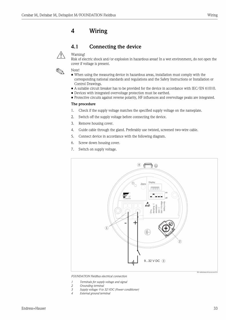
P01-xMx5xxxx-04-xx-xx-xx-014
FOUNDATION Fieldbus electrical connection
1 Terminals for supply voltage and signal
2 Grounding terminal
3 Supply voltage: 9 to 32 VDC (Power conditioner)
4 External ground terminal
on
offoff
DisplayZero
sim
ula
tio
n
TM
FOUNDATIONFOUNDATION
SW
/ P
2=
Hig
hS
W /
P2
=H
igh
SW
/�
SW
/�
da
mp
ing
da
mp
ing
de
lta
p o
nly
de
lta
p o
nly
9...32 V DC
- +1
2
3
4
Wiring Cerabar M, Deltabar M, Deltapilot M/FOUNDATION Fieldbus
34 Endress+Hauser
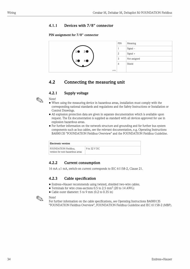
4.1.1 Devices with 7/8" connector
PIN assignment for 7/8" connector
4.2 Connecting the measuring unit
4.2.1 Supply voltage
! Note!
• When using the measuring device in hazardous areas, installation must comply with the
corresponding national standards and regulations and the Safety Instructions or Installation or
Control Drawings.
• All explosion protection data are given in separate documentation which is available upon
request. The Ex documentation is supplied as standard with all devices approved for use in
explosion hazardous areas.
• For further information on the network structure and grounding and for further bus system
components such as bus cables, see the relevant documentation, e.g. Operating Instructions
BA00013S "FOUNDATION Fieldbus Overview" and the FOUNDATION Fieldbus Guideline.
4.2.2 Current consumption
16 mA ±1 mA, switch-on current corresponds to IEC 61158-2, Clause 21.
4.2.3 Cable specification
• Endress+Hauser recommends using twisted, shielded two-wire cables.
• Terminals for wire cross-sections 0.5 to 2.5 mm2 (20 to 14 AWG)
• Cable outer diameter: 5 to 9 mm (0.2 to 0.35 in)
! Note!
For further information on the cable specifications, see Operating Instructions BA00013S
"FOUNDATION Fieldbus Overview", FOUNDATION Fieldbus Guideline and IEC 61158-2 (MBP).
(A703)
PIN Meaning
1 Signal –
2 Signal +
3 Not assigned
4 Shield
2
1
4
3
Electronic version
FOUNDATION Fieldbus,
version for non-hazardous areas
9 to 32 V DC

Cerabar M, Deltabar M, Deltapilot M/FOUNDATION Fieldbus Wiring
Endress+Hauser 35
4.2.4 Shielding/potential equalization
• You achieve optimum shielding against disturbances if the shielding is connected on both sides
(in the cabinet and on the device). If potential equalization currents are expected in the plant,
only ground shielding on one side, preferably at the transmitter.
• When using in hazardous areas, you must observe the applicable regulations.
Separate Ex documentation with additional technical data and instructions is included with all
Ex systems as standard.
4.3 Potential equalization
Hazardous area applications: Connect all devices to the local potential equalization.
Observe the applicable regulations.

Wiring Cerabar M, Deltabar M, Deltapilot M/FOUNDATION Fieldbus
36 Endress+Hauser
4.4 Overvoltage protection (optional)
Devices showing version "NA" in feature 610 "Mounted accessories" in the order code are equipped
with overvoltage protection (see also Technical Information TI00436P Cerabar M / TI00434P
Deltabar M / TI00437P Deltapilot M "Ordering information"). The overvoltage protection is
mounted at the factory on the housing thread for the cable gland and is approx. 70 mm (2.76 in) in
length (take additional length into account when installing).
The device is connected as specified in the following graphic. For details, see TI001013KEN,
XA01003KA3 and BA00304KA2.
4.4.1 Wiring
P01-xMx5xxxx-04-xx-xx-en-006
4.4.2 Installation
P01-xMx5xxxx-04-xx-xx-en-007
➀
➁
Unit to beprotected
Connectioncables
Incomingconnection cables
HAW569-DA2B
+
-
+
-Red
Black
+
-
Shield grounding
without
direct
➀➁
5
red
red
+
-
+
-
black
black5 7
10
10
15
➁
➂
min. 1.5 mm²
max. 3.75 Nm
max. 1.5 mm²
0.4 Nm
max. 2.5 mm²
➀
Shield grounding
➁➂
without
direct
➀ Screw coupling glued at the factory: hold in place with a wrench when loosening/tightening the coupling nut
Cerabar M, Deltabar M, Deltapilot M/FOUNDATION Fieldbus Wiring
Endress+Hauser 37
4.5 Post-connection check
Perform the following checks after completing electrical installation of the device:
• Does the supply voltage match the specifications on the nameplate?
• Is the device connected as per Section 4.1?
• Are all screws firmly tightened?
• Are the housing covers screwed down tight?
As soon as voltage is applied to the device, the green LED on the electronic insert lights up briefly
or the connected onsite display lights up.

Operation Cerabar M, Deltabar M, Deltapilot M/FOUNDATION Fieldbus
38 Endress+Hauser
5 Operation
5.1 Operating options
5.1.1 Operation without operating menu
5.1.2 Operation with an operating menu
Operation with an operating menu is based on an operation concept with "user roles" ä 42.
Operating options Explanation Graphic illustration Description
Local operation without
device display
The device is operated using the
operating key and DIP switches
on the electronic insert.
ä 40
Operating options Explanation Graphic illustration Description
Local operation
with device display
The device is operated using the
operating keys on the device
display.
ä 43
Remote operation via
FieldCare
The device is operated using the
FieldCare operating tool.
ä 48
on
off1 2 3 4 5
on
off
DisplayZero
sim
ula
tion
TM
FOUNDATION
SW
/ P
2=
Hig
h
SW
/�
dam
pin
g
delta p
only
E+–

Cerabar M, Deltabar M, Deltapilot M/FOUNDATION Fieldbus Operation
Endress+Hauser 39
5.1.3 Operation via FF communication protocol
Operating options Explanation Graphic illustration Description
Remote operation via
FieldCare
The device is operated using the
FieldCare operating tool.
ä 52
Remote operation via
the NI Tool
The device is operated using the
NI Tool.
ä 131

Operation Cerabar M, Deltabar M, Deltapilot M/FOUNDATION Fieldbus
40 Endress+Hauser
5.2 Operation without an operating menu
5.2.1 Position of operating elements
The operating key and DIP switches are located on the electronic insert in the device.
Function of the DIP switches
P01-Mxxxxxxx-19-xx-xx-xx-001
Fig. 20: FOUNDATION Fieldbus electronic insert
1 DIP switch for locking/unlocking parameters relevant to the measured value
2 DIP switch for switching damping on/off
3 DIP switch for simulation
4/5 DIP switch only for Deltabar M:
Switch 4: "SW/Square root"; used to control the output characteristics
Switch 5: "SW/P2-High"; used to determine the high-pressure side
6 Slot for optional onsite display
7 Green LED to indicate successful operation (position adjustment, reset, PowerUp-Reset)
8 Operating key for position adjustment or reset (zero)
Switches Symbol/
labeling
Switch position
"off" "on"
1 The device is unlocked.
Parameters relevant to the measured value
can be modified.
The device is locked.
Parameters relevant to the measured value
cannot be modified.
2 damping Damping is switched off.
The output signal follows measured value
changes without any delay.
Damping is switched on.
The output signal follows measured value
changes with the delay time .1)
1) The value for the delay time can be configured via the operating menu ("Setup" -> "Damping").
Factory setting: = 2 s or as per order specifications.
3 Simulation The simulation mode is switched off (factory
setting).
The simulation mode is switched on.
The following switches only for Deltabar M:
4 SW/ The output characteristics is defined by the
setting in the operating menu.
• "Setup" -> "Measuring mode"
• "Setup" -> "Extended setup" ->
The measuring mode is "flow" and the
output characteristics is "Square root"
regardless of the settings in the operating
menu.
5 SW/P2= High The high-pressure (+/HP) side is defined by
the setting in the operating menu.
("Setup" -> "High Press. Side")
The high-pressure side (+/HP) is allocated to
the P2 pressure connection regardless of the
setting in the operating menu.
➂➁
➅
on
off
SW
/ P
2=
Hig
h
Sim
ula
tio
n
SW
/�
dam
pin
g
1 2 3 4 5
➃➄➀
➆
➇ on
off
DisplayZero
sim
ula
tio
n
TM
FOUNDATION
SW
/ P
2=
Hig
h
SW
/�
dam
pin
g
de
lta
p o
nly

Cerabar M, Deltabar M, Deltapilot M/FOUNDATION Fieldbus Operation
Endress+Hauser 41
Function of the operating elements
Performing position adjustment on site
! Note!
• Operation must be unlocked. ä 48, Section 5.3.5 "Locking/unlocking operation".
• The device is configured for the Pressure measuring mode as standard.
– Operation via FF configuration program: In the Pressure Transducer Block, you can change the
measuring mode by means of the PRIMARY_VALUE_TYPE parameter.
• The pressure applied must be within the nominal pressure limits of the sensor. See information
on the nameplate.
• To reconcile the parameter database, perform a "Reconcile device" (after position adjustment)
with the FF host.
Perform position adjustment:
1. Pressure is present at device.
2. Press key for at least 3 seconds.
3. If the LED on the electronic insert lights up briefly, the pressure applied has been accepted for
position adjustment.
If the LED does not light up, the pressure applied was not accepted. Observe the input limits.
For error messages, ä 211, Section 10.1 "Messages".
5.2.2 Locking/unlocking operation
Once you have entered all the parameters, you can lock your entries against unauthorized and
undesired access.
! Note!
If operation is locked by means of the DIP switch, you can only unlock operation again by means of
the DIP switch. If operation is locked by means of the operating menu, you can only unlock
operation again using the operating menu.
Locking/unlocking via DIP switches
DIP switch 1 on the electronic insert is used to lock/unlock operation.
ä 40, "Function of the DIP switches".
Operating key Meaning
"Zero"
pressed for at least
3 seconds
Position adjustment (zero point correction)
Press key for at least 3 seconds. The LED on the electronic insert lights up briefly if the pressure
applied has been accepted for position adjustment.
See also the following Section "Performing position adjustment on site.''
"Zero"
pressed for at least
12 seconds
Reset
All parameters are reset to the order configuration.

Operation Cerabar M, Deltabar M, Deltapilot M/FOUNDATION Fieldbus
42 Endress+Hauser
5.3 Operation with an operating menu
5.3.1 Operation concept
The operation concept makes a distinction between the following user roles:
5.3.2 Structure of the operating menu
User role Meaning
Operator Operators are responsible for the devices during normal "operation". This is usually limited to
reading process values either directly at the device or in a control room. If the work with the
devices extends beyond value read-off tasks, the tasks involve simple, application-specific functions
that are used in operation. Should an error occur, these users simple forward the information on
the errors but do not intervene themselves.
Service engineer/
technician
Service engineers usually work with the devices in the phases following device commissioning.
They are primarily involved in maintenance and troubleshooting activities for which simple settings
have to be made at the device.
Technicians work with the devices over the entire life cycle of the product.
Thus, commissioning and advanced settings and configurations are some of the tasks they have to
carry out.
Expert Experts work with the devices over the entire product life cycle, but their device requirements are
often extremely high. Individual parameters/functions from the overall functionality of the devices
are required for this purpose time and again.
In addition to technical, process-oriented tasks, experts can also perform administrative tasks
(e.g. user administration).
"Experts" can avail of the entire parameter set.
User role Submenu Meaning/use
Operator Language Only consists of the "Language" parameter (000) where the operating language for
the device is specified.
The language can always be changed even if the device is locked.
Operator Display/operat. Contains parameters that are needed to configure the measured value display
(selecting the values displayed, display format, display contrast, etc.).
With this submenu, users can change the measured value display without affecting
the actual measurement.
Service
engineer/
technician
Setup Contains all the parameters that are needed to commission measuring operations.
This submenu has the following structure:
• Standard setup parameters
A wide range of parameters, which can be used to configure a typical application,
is available at the start. The measuring mode selected determines which
parameters are available.
After making settings for all these parameters, the measuring operation should be
completely configured in the majority of cases.
• "Extended setup" submenu
The "Extended setup" submenu contains additional parameters for more in-depth
configuration of the measurement operation to convert the measured value and
to scale the output signal.
This menu is split into additional submenus depending on the measuring mode
selected.
Service
engineer/
technician
Diagnosis Contains all the parameters that are needed to detect and analyze operating errors.
This submenu has the following structure:
• Diagnostic list
Contains up to 10 error messages currently pending.
• Event logbook
Contains the last 10 error messages (no longer pending).
• Instrument info
Contains information on the device identification.
• Measured values
Contains all the current measured values
• Simulation
Is used to simulate pressure, level, flow and alarm/warning.
• Reset

Cerabar M, Deltabar M, Deltapilot M/FOUNDATION Fieldbus Operation
Endress+Hauser 43
! Note!
For an overview of the entire operating menu: ä 102 ff.
Direct access to parameters
The parameters can only be accessed directly via the "Expert" user role.
5.3.3 Operation with a device display (optional)
A 4-line liquid crystal display (LCD) is used for display and operation. The onsite display shows
measured values, dialog texts, fault messages and notice messages.
For easy operation the display can be taken out of the housing (see figure steps 1 to 3). It is
connected to the device through a 90 mm (3.54 in) cable.
The display of the device can be turned in 90° stages (see figure steps 4 to 6).
Depending on the orientation of the device, this makes it easy to operate the device and read the
measured values.
P01-Mxxxxxxx-19-xx-xx-xx-008
Expert Expert Contains all the parameters of the device (including those in one of the submenus).
The "Expert" submenu is structured by the function blocks of the device. It thus
contains the following submenus:
• System
Contains general device parameters that neither affect measurement nor
integration into a distributed control system.
• Measurement
Contains all the parameters for configuring the measurement.
• Communication
Contains all the parameters of the FOUNDATION Fieldbus interface.
• Application
Contains all the parameters for configuring the functions that go beyond the
actual measurement (e.g. totalizer).
• Diagnosis
Contains all the parameters that are needed to detect and analyze operating
errors.
User role Submenu Meaning/use
Parameter name Description
Direct access (119)
Entry
Menu path:
Expert Direct access
Use this function to enter a parameter code for direct access.
User input:
• Enter the desired parameter code.
Factory setting:
0
1. 2. 3.
4. 5. 6.
Operation Cerabar M, Deltabar M, Deltapilot M/FOUNDATION Fieldbus
44 Endress+Hauser
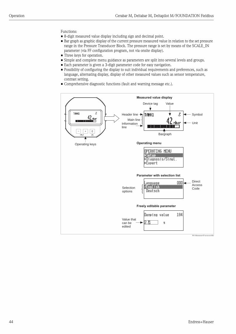
Functions:
• 8-digit measured value display including sign and decimal point.
• Bar graph as graphic display of the current pressure measured value in relation to the set pressure
range in the Pressure Transducer Block. The pressure range is set by means of the SCALE_IN
parameter (via FF configuration program, not via onsite display).
• Three keys for operation.
• Simple and complete menu guidance as parameters are split into several levels and groups.
• Each parameter is given a 3-digit parameter code for easy navigation.
• Possibility of configuring the display to suit individual requirements and preferences, such as
language, alternating display, display of other measured values such as sensor temperature,
contrast setting.
• Comprehensive diagnostic functions (fault and warning message etc.).
P01-Mxxxxxxx-07-xx-xx-xx-002
E+–
Symbol
Operating keys
ValueDevice tag
Measured value display
Unit
Bargraph
Operating menu
Parameter with selection list
Freely editable parameter
DirectAccessCode
Value thatcan beedited
Selectionoptions
Header line
Informationline
Main line

Cerabar M, Deltabar M, Deltapilot M/FOUNDATION Fieldbus Operation
Endress+Hauser 45
The following table illustrates the symbols that can appear on the onsite display. Four symbols can
occur at one time.
Operating keys on the display and operating module
Symbol Meaning
Lock symbol
The operation of the device is locked. To unlock the device, ä 48, Locking/unlocking
operation.
Communication symbol
Data transfer via communication
Square root symbol (only Deltabar M)
Active measuring mode "Flow measurement"
Error message "Out of specification"
The device is being operated outside its technical specifications (e.g. during warmup or
cleaning processes).
Error message "Service mode"
The device is in the service mode (during a simulation, for example).
Error message "Maintenance required"
Maintenance is required. The measured value remains valid.
Error message "Failure detected"
An operating error has occurred. The measured value is no longer valid.
Simulation symbol
Simulation mode is activated. DIP switch 2 for simulation is set to "On".
See also Section 5.2.1 "Position of operating elements" and ä 49, Section 5.3.6
"Simulation".
Operating key(s) Meaning
O – Navigate downwards in the picklist
– Edit the numerical values and characters within a function
S – Navigate upwards in the picklist
– Edit the numerical values and characters within a function
F– Confirm entry
– Jump to the next item
– Selection of a menu item and activation of the editing mode
O and FContrast setting of onsite display: darker
S and FContrast setting of onsite display: brighter
O and SESC functions:
– Exit the edit mode for a parameter without saving the changed value.
– You are in a menu at a selection level. Each time you press the keys simultaneously, you
go up a level in the menu.
�
�
�
�
Operation Cerabar M, Deltabar M, Deltapilot M/FOUNDATION Fieldbus
46 Endress+Hauser
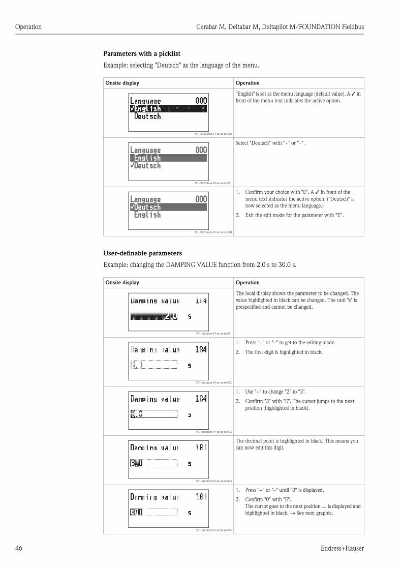
Parameters with a picklist
Example: selecting "Deutsch" as the language of the menu.
User-definable parameters
Example: changing the DAMPING VALUE function from 2.0 s to 30.0 s.
Onsite display Operation
P01-PMD55xxx-19-xx-xx-xx-002
"English" is set as the menu language (default value). A ✓ in
front of the menu text indicates the active option.
P01-PMD55xxx-19-xx-xx-xx-001
Select "Deutsch" with "+" or "–" .
P01-PMD55xxx-19-xx-xx-xx-000
1. Confirm your choice with "E". A ✓ in front of the
menu text indicates the active option. ("Deutsch" is
now selected as the menu language.)
2. Exit the edit mode for the parameter with "E" .
Onsite display Operation
P01-xxxxxxxx-19-xx-xx-en-001
The local display shows the parameter to be changed. The
value highlighted in black can be changed. The unit "s" is
prespecified and cannot be changed.
P01-xxxxxxxx-19-xx-xx-en-002
1. Press "+" or "–" to get to the editing mode.
2. The first digit is highlighted in black.
P01-xxxxxxxx-19-xx-xx-en-003
1. Use "+" to change "2" to "3".
2. Confirm "3" with "E". The cursor jumps to the next
position (highlighted in black).
P01-xxxxxxxx-19-xx-xx-en-004
The decimal point is highlighted in black. This means you
can now edit this digit.
P01-xxxxxxxx-19-xx-xx-en-005
1. Press "+" or "–" until "0" is displayed.
2. Confirm "0" with "E".
The cursor goes to the next position. is displayed and
highlighted in black. See next graphic.

Cerabar M, Deltabar M, Deltapilot M/FOUNDATION Fieldbus Operation
Endress+Hauser 47
Accepting the pressure present
Example: setting position adjustment
P01-xxxxxxxx-19-xx-xx-en-006
Use "E" to save the new value and exit the editing mode.
See next graphic.
P01-xxxxxxxx-19-xx-xx-en-007
The new value for the damping is 30.0 s.
– Go to the next parameter with "E" .– You can get back to the editing mode with "+" or "–".
Onsite display Operation
P01-PMD55xxx-19-xx-xx-xx-009
The pressure for position adjustment is present at the
device.
P01-PMD55xxx-19-xx-xx-xx-010
Use "+" or "–" to switch to the "Confirm" option. The active
option is highlighted in black.
P01-PMD55xxx-19-xx-xx-xx-011
Accept the pressure present as position adjustment with the
"E" key. The device confirms the adjustment and goes back
to the "Pos. zero adjust" parameter.
P01-PMD55xxx-19-xx-xx-xx-009
Exit the edit mode for the parameter with "E" .
Onsite display Operation

Operation Cerabar M, Deltabar M, Deltapilot M/FOUNDATION Fieldbus
48 Endress+Hauser
5.3.4 Operation via FieldCare
FieldCare is an Endress+Hauser asset management tool based on FDT technology. With FieldCare,
you can configure all Endress+Hauser devices as well as devices from other manufacturers that
support the FDT standard. Hard- and software requirements can be found on the Internet:
www.endress.com ➞ Search for: FieldCare ➞ FieldCare ➞ Technical data.
FieldCare supports the following functions:
• Configuration of transmitters in online/offline mode
• Loading and saving device data (upload/download): see parameter "Download select" ä 113
in operating menu or via Resource block ä 166.
• Documentation of the measuring point
• Offline parametrization of transmitters
! Note!
• In "Level expert" measuring mode, the configuration data which were generated by FDT upload
cannot be saved back again (FDT download); they are used solely to document the configuration.
• Further information on FieldCare can be found on the Internet (http://www.endress.com,
Download Search for: FieldCare).
• As not all internal device dependencies can be mapped in offline operation, the consistency of the
parameters must be checked before the parameters are transmitted to the device.
• All the function blocks are set to the OOS mode following a download. The DIP switches must
be set to the as-delivered state for this purpose (see Figure ä 40).
5.3.5 Locking/unlocking operation
Once you have entered all the parameters, you can lock your entries against unauthorized and
undesired access.
Locked operation is indicated as follows:
• By the symbol on the onsite display
• The parameters are grayed out in FieldCare and the handheld terminal, which means they cannot
be edited. Indicated in the corresponding "Lockstate/STATUS_LOCKING" parameter.
Parameters which refer to how the display appears, e.g. "Language (000)", can still be altered.
! Note!
If operation is locked by means of the DIP switch, you can only unlock operation again by means of
the DIP switch. If operation is locked by means of the operating menu, you can only unlock
operation again using the operating menu.
The "Operator code (021)" parameter is used to lock and unlock the device.
The release code is defined in the "Code definition (023)" parameter.
Parameter name Description
Operator code (021)
Entry
Menu path:
Setup Extended setup Operator code (021)
Use this function to enter a code to lock or unlock operation.
User input:
• To lock: Enter a number the release code (value range: 1 to 9999).
• To unlock: Enter the release code.
! Note!
The release code is "0" in the order configuration. Another release code can be defined in
the "Code definition (023)" parameter.
If the user has forgotten the release code, the release code can be visible by entering the
number "5864".
Factory setting:
0

Cerabar M, Deltabar M, Deltapilot M/FOUNDATION Fieldbus Operation
Endress+Hauser 49
5.3.6 Simulation
Simulate the output of the Analog Input Block as follows:
1. Set the "Simulation" DIP switch on the electronic insert to "On".
2. In the Analog Input Block, select the "Active" option by means of the "Simulate/SIMULATE"
record parameter, "Simulate En/Disable/ENABLE_DISABLE" element.
3. Enter the value and status for the "Simulate value/SIMULATION_VALUE"
and "Simulate status/SIMULATION_STATUS" elements. During the simulation, the output
value and status of the Analog Input Block are replaced by the simulated value and status. The
Output/OUT parameter shows the result.
4. End simulation (via "Simulate/SIMULATE" record parameter,
"Simulate En/Disable/ENABLE_DISABLE" element, "Disabled" option), set "Simulation" DIP
switch to "OFF".
! Note!
You can check your adjustment for the transmitter by means of the Simulation mode/
SIMULATION_MODE and Simulated Value/SIMULATED_VALUE parameters in the Diagnostic
Transducer Block. See Simulation mode/SIMULATION_MODE and Simulated Value/
SIMULATED_VALUE parameter description.
Parameter name Description
Code definition (023)
Entry
Menu path:
Setup Extended setup Code definition (023)
Use this function to enter a release code with which the device can be unlocked.
User input:
• A number between 0 and 9999
Factory setting:
0
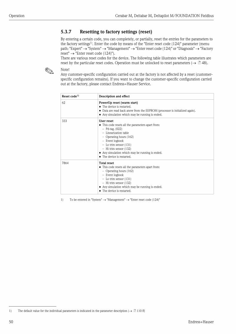
Operation Cerabar M, Deltabar M, Deltapilot M/FOUNDATION Fieldbus
50 Endress+Hauser
5.3.7 Resetting to factory settings (reset)
By entering a certain code, you can completely, or partially, reset the entries for the parameters to
the factory settings1). Enter the code by means of the "Enter reset code (124)" parameter (menu
path: "Expert" "System" "Management" "Enter reset code (124)" or "Diagnosis" "Factory
reset" "Enter reset code (124)").
There are various reset codes for the device. The following table illustrates which parameters are
reset by the particular reset codes. Operation must be unlocked to reset parameters ( ä 48).
! Note!
Any customer-specific configuration carried out at the factory is not affected by a reset (customer-
specific configuration remains). If you want to change the customer-specific configuration carried
out at the factory, please contact Endress+Hauser Service.
1) The default value for the individual parameters is indicated in the parameter description ( ä 110 ff)
Reset code1)
1) To be entered in "System" "Management" "Enter reset code (124)"
Description and effect
62 PowerUp reset (warm start)
• The device is restarted.
• Data are read back anew from the EEPROM (processor is initialized again).
• Any simulation which may be running is ended.
333 User reset
• This code resets all the parameters apart from:
– Pd-tag. (022)
– Linearization table
– Operating hours (162)
– Event logbook
– Lo trim sensor (131)
– Hi trim sensor (132)
• Any simulation which may be running is ended.
• The device is restarted.
7864 Total reset
• This code resets all the parameters apart from:
– Operating hours (162)
– Event logbook
– Lo trim sensor (131)
– Hi trim sensor (132)
• Any simulation which may be running is ended.
• The device is restarted.

Cerabar M, Deltabar M, Deltapilot M/FOUNDATION Fieldbus Operation
Endress+Hauser 51
5.4 FOUNDATION Fieldbus communication protocol
5.4.1 System architecture
The following diagram shows two typical examples of a FOUNDATION Fieldbus network with the
associated components.
P01-xxxxxxxx-02-xx-xx-xx-006
Fig. 21: FOUNDATION Fieldbus system architecture with associated components
FF-HSE: High Speed Ethernet, FF-H1: FOUNDATION Fieldbus-H1, LD: Linking Device FF-HSE/FF-H1,
PS: Bus Power Supply, SB: Safety Barrier, BT: Bus Terminator
The system can be connected in the following ways:
– A linking device makes the connection to higher-order fieldbus levels (e.g. High Speed Ethernet (HSE)) possible.
– An FF-H1 connecting card is needed for direct connection to a process control system.
! Note!
Further information on FOUNDATION Fieldbus can be found in Operating Instructions BA00013S
"FOUNDATION Fieldbus Overview, Installation and Commissioning Guidelines", the
FOUNDATION Fieldbus Specification or on the Internet at "http://www. fieldbus.org".
FF-H1
FF-H1
BT
BT
PS
PS
BT
SB
BT
FF-HSE
Industrial Network
LD

Operation Cerabar M, Deltabar M, Deltapilot M/FOUNDATION Fieldbus
52 Endress+Hauser
5.4.2 Number of devices
• Endress+Hauser devices meet the requirements specified by the FISCO model.
• Due to the low current consumption, the following can be operated at one bus segment when
installation is performed according to FISCO:
– Up to 6 devices for EEx ia, CSA and FM IS applications
– Up to 22 devices in all other applications, e.g. in non hazardous areas, EEx nA etc.
The maximum number of measuring devices at one bus segment is defined by their current
consumption, the performance of the bus coupler, and the required bus length.
5.4.3 Operation
You can obtain special configuration and operating programs from various manufacturers for the
configuration, such as the FieldCare operating program from Endress+Hauser ä 48,
Section 5.3.4 "Operation via FieldCare". These configuration programs make it possible to configure
FF functions and all the device-specific parameters. The predefined function blocks allow uniform
access to network and device data.
5.4.4 Network configuration
You require the following to configure a device and integrate it into an FF network:
• An FF configuration program
• The Cff file (Common File Format: *.cff)
• The device description (DD)
(Device Description format 4 : *sym, *ffo or
Device Description format 5 : *sy5, *ff5)
Pre-defined standard DDs, which can be obtained from FOUNDATION Fieldbus, are available for
the basic functions of measuring devices. You require the device-specific DD to be able to access all
the functions.
The files for the devices can be acquired as follows:
• Internet Endress+Hauser: http://www.endress.com Search for FOUNDATION Fieldbus
• Internet FOUNDATION Fieldbus: http://www.fieldbus.org
The device is integrated into the FF network as follows:
• Start the FF configuration program.
• Download the Cff and device description files (*.ffo, *.sym (for format 4) *ff5, *sy5 (for format 5)
to the system.
• Configure the interface, see Note.
• Configure the device for the measuring task and for the FF system.
! Note!
• For more in-depth information on integrating the device into the FF system, see the description
for the configuration software used.
• When integrating the field devices into the FF system, make sure you are using the right files. You
can read out the required version by means of the Device Revision/DEV_REV and DD Revision/
DD_REV parameters in the Resource Block.

Cerabar M, Deltabar M, Deltapilot M/FOUNDATION Fieldbus Operation
Endress+Hauser 53
5.4.5 Device identification and addressing
FOUNDATION Fieldbus identifies the device using its ID code and automatically assigns it a suitable
field address. The identity code cannot be changed.
The device appears in the network display once you have started the FF configuration program and
integrated the device into the network. The blocks available are displayed under the device name.
If the device description has not yet been loaded, the blocks report "Unknown" or "(UNK)".
The devices report as follows:
P01-xxxxxxxx-05-xx-xx-xx-004
Fig. 22: Typical display in a configuration program after the connection has been established
1 Device name
2 Serial number
–
–RS_00000000000 (RB2)
EH_Deltabar_M_5X_00000000000000
➀ ➁
TRD1_ (PCD)00000000000
DIAGNOSTIC_ (DIAGNOSTIC)000000000000
DISPLAY_ (DISP)00000000000
AI1_ (AI)000000000000
AI2_ (AI)000000000000
DO_ (DO)00000000000
ISEL_00000000000(ISB)
PID_00000000000(PID)
ARTH_00000000000(ARB)
CHAR_00000000000(SCB)
INTG_ (ITB)0000000000
DI_ (DI)00000000000
DP_FLOW_ (DPFLOW)000000000000
–
–
RS_00000000000 (RB2)
EH_Cerabar_M_5X_000000000000000
➀ ➁
TRD1_ (PCD)00000000000
DIAGNOSTIC_ (DIAGNOSTIC)00000000000
DISPLAY_ (DISP)00000000000
AI1_ (AI)00000000000
AI2_ (AI)00000000000
DO_ (DO)00000000000
ISEL_00000000000(ISB)
PID_00000000000(PID)
ARTH_00000000000(ARB)
CHAR_00000000000(SCB)
INTG_ (ITB)00000000000
DI_ (DI)00000000000
EH_Deltapilot_M_5X_000000000000000

Operation Cerabar M, Deltabar M, Deltapilot M/FOUNDATION Fieldbus
54 Endress+Hauser
5.4.6 Block model
With FOUNDATION Fieldbus, all the device parameters are categorized according to their
functional properties and task and are generally assigned to three different blocks.
A FOUNDATION Fieldbus device has the following block types:
• A Resource Block (device block):
This block contains all the device-specific features of the device.
• One or more Transducer Blocks
A Transducer Block contains all the measuring and device-specific parameters of the device. The
measuring principles, such as pressure or totalizers, are mapped in the Transducer Blocks.
• One or more function blocks:
Function blocks contain the automation functions of the device. A distinction is made between
different function blocks such as the Analog Input Block or PID Block. Each of these function
blocks is used to execute different application functions.
The function blocks can be connected by means of an FF configuration program, depending on the
automation task. The device thus takes on simple control functions, thereby relieving the workload
on the higher-order process control system.
The device has the following blocks:
• Resource Block (device block)
• 3 Transducer Blocks for all devices
– Pressure Transducer Block
This Block returns the output variables Primary Value/PRIMARY_VALUE and Secondary
Value/SECONDARY_VALUE. It contains all the parameters to configure the measuring device
for the measuring task such as measuring mode selection, linearization function and unit
selection.
– Display Transducer Block
This Block does not return any output variables. It contains all the parameters for configuring
the onsite display, such as Language/DISPLAY_LANGUAGE.
– Diagnostic Transducer Block
This Block does not return any output variables. It contains the simulation function for the
Pressure Transducer Block, parameters to configure the alarm response.
• In addition, 1 Transducer Block for Deltabar M
– DP_FLOW Block
This Block supplies the output variable Totalizer 1/TOTALIZER_1 and Totalizer 2/
TOTALIZER_2. It contains all the parameters required for configuring these totalizers.
• Function blocks in all devices
– 2 Analog Input Blocks (AI) (permanent block - cannot be deleted)
– Discrete Output Block (DO) (permanent block - cannot be deleted)
– Discrete Input Block (DI) (permanent block - cannot be deleted)
– Input Selector Block (ISB) (permanent block - cannot be deleted)
– PID Block (PID) (non-permanent block - can be deleted)
– Arithmetic Block (ARB) (non-permanent block - can be deleted)
– Signal Characterizer Block (SCB) (non-permanent block - can be deleted)
– Integrator Block (IT) (non-permanent block - can be deleted)
In addition to the pre-instantiated blocks already mentioned, the following blocks can also be
instantiated:
With Deltabar M:
• 3 Analog Input Blocks (AI)
• 4 Discrete Input Blocks (DI)
• 1 Discrete Output Block (DO)
• 2 Input Selector Block (ISB)
• 2 PID Blocks (PID)
• 2 Arithmetic Blocks (ARTH)
• 2 Signal Characterizer Blocks (SCB)
• 2 Integrator Blocks (IT)
With Cerabar M and Deltapilot M :
• 2 Analog Input Blocks (AI)

Cerabar M, Deltabar M, Deltapilot M/FOUNDATION Fieldbus Operation
Endress+Hauser 55
• 4 Discrete Input Blocks (DI)
• 2 Input Selector Block (ISB)
• 2 PID Blocks (PID)
• 2 Arithmetic Blocks (ARTH)
• 2 Signal Characterizer Blocks (SCB)
• 2 Integrator Blocks (IT)
Up to 20 blocks can be instantiated in the device altogether, including the blocks already
instantiated. For instantiating blocks, see the appropriate Operating Instructions of the configuration
program used.
! Note!
Endress+Hauser Guideline BA00062S.
The guideline provides an overview of the standard function blocks that are described in
FOUNDATION Fieldbus Specifications FF 890 - 894.
It is designed to help operators use the blocks implemented in the Endress+Hauser field devices.

Operation Cerabar M, Deltabar M, Deltapilot M/FOUNDATION Fieldbus
56 Endress+Hauser
Block configuration when device is delivered
The block model shown below illustrates the block configuration when the device is delivered.
P01-xxxxxxxx-02-xx-xx-en-005
Fig. 23: Block configuration when device is delivered
The Pressure Transducer Block supplies the primary value depending on the measuring mode, and
a secondary value
• for Cerabar/Deltapilot, secondary value = sensor temperature.
• for Deltabar, secondary value = Measured pressure.
By means of the Channel/CHANNEL parameter, the measured values (primary value, secondary
value, etc.) are transferred to an Analog Input Block from the Transducer Block, see also the
following section).
The Discrete Output, PID, Arithmetic, Signal Characterizer and Input Selector Block are not
connected in the as-delivered state (IT, DI).
Deltabar M:
In the DP_FLOW Transducer Block, the flow is totalized in the "Flow" measuring mode and output
by means of the Totalizer 1/TOTALIZER_1 parameter.
PressureTransducer Block
Analog Input Block 1CHANNEL = 1L_TYPE = Direct
Analog Input Block 2CHANNEL = 3L_TYPE = Direct
DisplayTransducer Block
DiagnosticTransducer Block
Primary value
Resource Block
IntegratorBlock
Discrete InputBlock
PID Block Input SelectorBlock
SignalCharacterizerBlock
Discrete OutputBlock
Arithmetic Block
PressureTransducer Block
Analog Input Block 1CHANNEL = 1L_TYPE = Direct
Analog Input Block 2CHANNEL = 2L_TYPE = Direct
DisplayTransducer Block
DiagnosticTransducer Block
Primary value
Secondary value
Resource Block
Input SelectorBlock
SignalCharacterizerBlock
Discrete OutputBlock
Arithmetic Block PID Block
IntegratorBlock
Discrete InputBlock
Deltabar M
Cerabar M / Deltapilot M
DP flow Block
Measured variable
SensorSignal evaluation
Displaywith scaling
Measured variable
SensorSignal evaluation
Displaywith scaling

Cerabar M, Deltabar M, Deltapilot M/FOUNDATION Fieldbus Operation
Endress+Hauser 57
! Note!
Please note that links between the blocks are deleted and the FF parameters are reset to the default
values following a reset by means of the Restart/RESTART parameter in the Resource Block,
"Default" option.
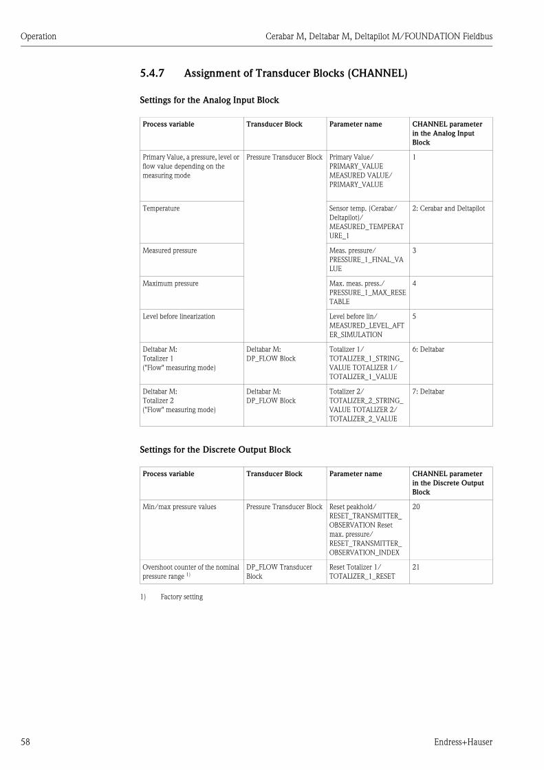
Operation Cerabar M, Deltabar M, Deltapilot M/FOUNDATION Fieldbus
58 Endress+Hauser
5.4.7 Assignment of Transducer Blocks (CHANNEL)
Settings for the Analog Input Block
Settings for the Discrete Output Block
Process variable Transducer Block Parameter name CHANNEL parameter
in the Analog Input
Block
Primary Value, a pressure, level or
flow value depending on the
measuring mode
Pressure Transducer Block Primary Value/
PRIMARY_VALUE
MEASURED VALUE/
PRIMARY_VALUE
1
Temperature Sensor temp. (Cerabar/
Deltapilot)/
MEASURED_TEMPERAT
URE_1
2: Cerabar and Deltapilot
Measured pressure Meas. pressure/
PRESSURE_1_FINAL_VA
LUE
3
Maximum pressure Max. meas. press./
PRESSURE_1_MAX_RESE
TABLE
4
Level before linearization Level before lin/
MEASURED_LEVEL_AFT
ER_SIMULATION
5
Deltabar M:
Totalizer 1
("Flow" measuring mode)
Deltabar M:
DP_FLOW Block
Totalizer 1/
TOTALIZER_1_STRING_
VALUE TOTALIZER 1/
TOTALIZER_1_VALUE
6: Deltabar
Deltabar M:
Totalizer 2
("Flow" measuring mode)
Deltabar M:
DP_FLOW Block
Totalizer 2/
TOTALIZER_2_STRING_
VALUE TOTALIZER 2/
TOTALIZER_2_VALUE
7: Deltabar
Process variable Transducer Block Parameter name CHANNEL parameter
in the Discrete Output
Block
Min/max pressure values Pressure Transducer Block Reset peakhold/
RESET_TRANSMITTER_
OBSERVATION Reset
max. pressure/
RESET_TRANSMITTER_
OBSERVATION_INDEX
20
Overshoot counter of the nominal
pressure range 1)
1) Factory setting
DP_FLOW Transducer
Block
Reset Totalizer 1/
TOTALIZER_1_RESET
21

Cerabar M, Deltabar M, Deltapilot M/FOUNDATION Fieldbus Operation
Endress+Hauser 59
Discrete Input Block settings
Alarm conditions Transducer Block Parameter name Parameter CHANNEL,
Discrete Input Block
General device error
Diagnostic TRD
Diagnostic code/
ACTUAL_HIGHEST_A
LARM
10
Configuration error 11
Sensor overpressure 12
Sensor underpressure 13
Temperature measured value overrange
(Cerabar and Deltapilot)
14
Pressure measured value overrange 15

Operation Cerabar M, Deltabar M, Deltapilot M/FOUNDATION Fieldbus
60 Endress+Hauser
5.4.8 Index tables of Endress+Hauser parameters
The following tables list the manufacturer-specific device parameters for the Resource Block, the
Transducer Blocks and the Analog Input Blocks. For the FF parameters, see either the
FF specification or descriptions from Page 131 ff.
General explanatory remarks
Data type
• DS: data structure, contains data types such as unsigned8, Octet String etc.
• Float: IEEE 754 format
• Visible String: ASCII coded
• Unsigned:
– Unsigned8: value range = 0 to 255
– Unsigned16: value range = 0 to 65535
– Unsigned32: value range = 0 to 4294967295
Storage Class
• Cst: constant parameter
• D: dynamic parameter
• N: nonvolatile parameter
• S: static parameter
If this is a write parameter, the MODE_BLK column indicates the block mode in which the
parameter can be written. Some parameters can only be written in the OOS block mode.
The "Reset codes" column indicates which reset codes reset the parameter.
Resource Block
Parameter name, "Label parameter" option and
display in FieldCare / parameter name in
accordance with DD
Index Data type Size
(Byte)
Storage
Class
Read Write MODE_BLK Reset
codes
Page
Device dialog/DEVICE_DIALOG 42 Unsigned8 1 D x ä 165
Operator code/S_W_LOCK 43 Unsigned16 2 S x x wr for Auto, OOS 7864, 333 ä 165
Lockstate/STATUS_LOCKING 44 Unsigned8 1 D x ä 165
DIP switch/SWITCH_STATUS_LIST 45 Unsigned8 1 S x ä 165
Electr. serial no./ ELECTRONIC_SERIAL _NUMBER 46 Visible String 16 S x ä 165
Sci octet str/SCI_OCTET_STRING 47 Visible String 40 D x x wr for Auto, OOS ä 165
Download select./DOWNLOAD_OVERWRITE_SELECTION 48 Unsigned8 1 D x x wr for Auto, OOS ä 166
Code definition/USER_S_W_UNLOCK 49 Unsigned16 1 S x x wr for Auto, OOS ä 166
Capability level/CAPABILITY_LEVEL 50 Unsigned8 1 D x ä 166
Compat. level/COMPATIBILITY_LEVEL 51 Unsigned8 1 S x ä 166
ENP version/FF_E_N_P_VERSION 52 Visible String 32 S x x ä 166
Pd-tag/FF_PD_TAG 53 Visible String 32 D x x wr for Auto, OOS ä 166
Serial number/DEVICE_SERIAL_NUMBER 54 Visible String 16 S x wr for Auto, OOS ä 167
Order code part 1/E_N_P_ORDER_CODE_1 55 Visible String 32 S x wr for Auto, OOS ä 167
Order code part 2/E_N_P_ORDER_CODE_2 56 Visible String 32 S x wr for Auto, OOS ä 167
Order code/DEVICE_ORDER_IDENT 57 Visible String 32 S x wr for Auto, OOS ä 167
Firmware version/FF_SOFTWARE_REVISION 58 Visible String 32 S x ä 167
Hardware rev./FF_HARDWARE_VERSION 59 Visible String 16 S x ä 167
FF com stack ver/FF_COM_VERSION 60 Visible String 16 S x ä 167
MS res directory/MS_RES_ DIRECTORY 61 Unsigned8 10 S x ä 167
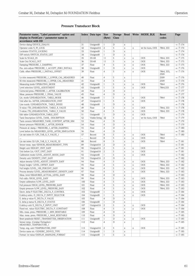
Cerabar M, Deltabar M, Deltapilot M/FOUNDATION Fieldbus Operation
Endress+Hauser 61
Pressure Transducer Block
Parameter name, "Label parameter" option and
display in FieldCare / parameter name in
accordance with DD
Index Data type Size
(Byte)
Storage
Class
Read Write MODE_BLK Reset
codes
Page
Device dialog/DEVICE_DIALOG 31 Unsigned8 1 D x ä 174
Operator code/S_W_LOCK 32 Unsigned16 2 S x x wr for Auto, OOS 7864, 333 ä 174
Lockstate/STATUS_LOCKING 33 Unsigned8 1 D x ä 174
DIP switch/SWITCH_STATUS_LIST 34 Unsigned8 1 D x ä 174
Scale In/SCALE_IN 35 DS-68 11 S x x OOS 7864, 333 ä 175
Scale Out/SCALE_OUT 36 DS-68 11 S x x OOS 7864, 333 ä 175
Damping/PRESSURE_1_DAMPING 37 Float 4 S x x OOS 7864, 333 ä 175
Pos. zero adjust/PRESSURE_1_ACCEPT_ZERO_INSTALL 38 Unsigned8 1 D x x OOS ä 176
Calib. offset/PRESSURE_1_INSTALL_OFFSET 39 Float 4 S x x OOS 7864, 333,
2509
ä 176
Lo trim measured/PRESSURE_1_LOWER_CAL_MEASURED 40 Float 4 S x 2509 ä 176
Hi trim measured/PRESSURE_1_UPPER_CAL_MEASURED 41 Float 4 S x 2509 ä 176
Measuring mode/OPERATING_MODE 42 Unsigned8 1 S x x OOS 7864 ä 176
Level selection/LEVEL_ADJUSTMENT 43 Unsigned8 1 S x x OOS 7864,333 ä 177
Corrected press./PRESSURE_1_AFTER_CALIBRATION 44 Float 4 D x ä 177
Meas. pressure/PRESSURE_1_FINAL_VALUE 45 Float 4 D x ä 177
Lin. mode/LINEARIZATION_ TABLE_MODE 46 Unsigned8 1 S x x OOS 7864 ä 178
Unit after lin./AFTER_LINEARIZATION_UNIT 47 Unsigned16 1 S x x OOS ä 178
Line numb./LINEARIZATION_ TABLE_INDEX 48 Unsigned8 1 D x x ä 178
X-value:/TB_LINEARIZATION_ TABLE_X_VALUE 49 Float 4 S x x OOS 7864, 333 ä 178
Y-value:/TB_LINEARIZATION_ TABLE_Y_VALUE 50 Float 4 S x x OOS 7864, 333 ä 178
Edit table/LINEARIZATION_TABLE_EDIT 51 Unsigned8 1 D x x OOS ä 179
Tank Description/LEVEL_TANK_ DESCRIPTION 52 Visible String 32 S x x wr for Auto, OOS 7864 ä 179
Tank content/MEASURED_TANK_CONTENT_AFTER_SIM 53 Float 4 D x ä 179
Sensor pressure/PRESSURE_1_AFTER_SENSOR 54 Float 4 D x ä 179
Pressure af. damp./ PRESSURE_1_AFTER_DAMPING 55 Float 4 D x ä 180
Level before lin/MEASURED_LEVEL_AFTER_SIMULATION 56 Float 4 D x ä 180
Lin tab index 01/LIN_TAB_X_Y_VALUE_1 57 Record 8 S x x OOS 7864 ä 180
... ... Record 8 S x x OOS 7864 ...
Lin tab index 32/LIN_TAB_X_Y_VALUE_32 88 Record 8 S x x OOS 7864 ä 181
Sensor meas. type/SENSOR_MEASUREMENT_TYPE 89 Unsigned16 2 D x ä 181
Height unit/HEIGHT_UNIT_EASY 90 Unsigned16 2 S x x OOS ä 181
Unit before Lin./OUT_UNIT_EASY 91 Unsigned16 2 S x x OOS ä 181
Calibration mode/LEVEL_ADJUST_MODE_EASY 92 Unsigned8 1 S x x OOS ä 182
Density unit/DENSITY_UNIT_EASY 93 Unsigned16 2 D x ä 182
Adjust density/LEVEL_ADJUST_DENSITY_EASY 94 Float 4 S x x OOS 7864, 333 ä 182
Empty height/ LEVEL_OFFSET_EASY 95 Float 4 S x x OOS 7864, 333 ä 182
Full height/LEVEL_100_PERCENT_EASY 96 Float 4 S x x OOS 7864, 333 ä 182
Process density/LEVEL_MEASUREMENT_DENSITY_EASY 97 Float 4 S x x OOS 7864, 333 ä 183
Meas. level/MEASURED_ACTUAL_LEVEL_EASY 98 Float 4 D x ä 183
Full calib./HIGH_LEVEL_EASY 99 Float 4 S x x OOS 7864, 333 ä 183
Empty calibration/LOW_LEVEL_EASY 100 Float 4 S x x OOS 7864, 333 ä 183
Full pressure/HIGH_LEVEL_PRESSURE_EASY 101 Float 4 S x x OOS 7864, 333 ä 183
Empty pressure/LOW_LEVEL_PRESSURE_EASY 102 Float 4 S x x OOS 7864, 333 ä 183
Electr. delta P/ELECTRIC_DELTA_P_CONTROL 103 Unsigned8 1 S x x OOS ä 184
E.delta p selec./E_DELTA_P_INPUT_SELECTOR 104 Unsigned8 1 S x x OOS ä 184
E. delta p value/E_DELTA_P_VALUE 105 Float 4 D x ä 184
E. delta p status/E_DELTA_P_STATUS 106 Unsigned8 1 D x ä 184
E.delta p unit/E_DELTA_P_INPUT_UNIT 107 Unsigned16 2 S x x OOS ä 184
Fixed ext. value/ELECTRIC_DELTA_P_CONSTANT 108 Float 4 S x x OOS ä 184
Min. meas. press./PRESSURE_1_MIN_RESETABLE 109 Float 4 D x ä 185
Max. meas. press./PRESSURE_1_MAX_RESETABLE 110 Float 4 D x ä 185
Reset peakhold/RESET_TRANSMITTER_OBSERVATION 111 Unsigned8 1 D x x OOS ä 185
Sensor temp. (Cerabar/Deltapilot)/
MEASURED_TEMPERATURE_1
112 Float 4 D x ä 185
Temp. eng. unit/TEMPERATURE_UNIT 113 Unsigned16 2 S x x OOS ä 185
Device name str./GENERIC_DEVICE_TYPE 114 Unsigned8 1 S x ä 185
Format 1st value/DISPLAY_MAINLINE_FORMAT 115 Unsigned8 1 S x ä 185

Operation Cerabar M, Deltabar M, Deltapilot M/FOUNDATION Fieldbus
62 Endress+Hauser
DP_FLOW Block (Deltabar M)
Display Transducer Block
Parameter name, "Label parameter" option and
display in FieldCare / parameter name in
accordance with DD
Index Data type Size
(Byte)
Storage
Class
Read Write BLK_MODE Reset
codes
Page
Device dialog/DEVICE_DIALOG 11 Unsigned8 1 D x ä 186
Operator code/S_W_LOCK 12 Unsigned16 2 S x x wr for Auto, OOS 7864 , 333 ä 186
Lockstate/STATUS_LOCKING 13 Unsigned8 1 D x ä 186
DIP switch/SWITCH_STATUS_LIST 14 Unsigned8 1 D x ä 186
Flow meas. type/FLOW_TYPE 15 Unsigned8 1 S x x OOS ä 186
Flow/FLOW_AFTER_SUPPRESSION 16 Float 4 D x ä 186
Flow unit/FLOW_UNIT 17 Unsigned16 2 S x x OOS 7864 , 333 ä 187
Set. L. Fl. Cut-off/CREEP_FLOW_SUPRESSION_OFF_THRES 18 Float 4 S x x OOS 7864 , 333 ä 188
Flow Max/MAX_FLOW 19 Float 4 S x x OOS ä 188
Pressure af. damp./ PRESSURE_1_AFTER_DAMPING 20 Float 4 D x ä 189
Max press. flow/FLOW_MAX_PRESSURE 21 Float 4 S x x OOS 7864 , 333 ä 189
Press. eng. unit/PRESSURE_1_UNIT 22 Unsigned16 2 S x x OOS ä 189
Totalizer 1/TOTALIZER_1 23 DS-65 5 D x ä 190
Eng. unit total. 1/TOTALIZER_1_UNIT 24 Unsigned16 2 S x x OOS 7864 , 333 ä 190
Totalizer 1 mode/TOTALIZER_1_MODE 25 Unsigned8 1 S x x OOS ä 190
Total. 1 failsafe/TOTALIZER_1_FAIL_ SAFE_MODE 26 Unsigned8 1 S x x OOS ä 190
Reset Totalizer 1/TOTALIZER_1_RESET 27 Unsigned8 1 D x x OOS ä 190
Totalizer 1/TOTALIZER_1_STRING_VALUE 28 Visible String 8 D x ä 190
Totalizer 1 overflow/TOTALIZER_1_STRING_OVERFLOW 29 Visible String 8 D x ä 190
Totalizer 2/TOTALIZER_2 30 DS-65 5 D x ä 191
Eng. unit total. 2/TOTALIZER_2_UNIT 31 Unsigned16 2 S x x OOS 7864 , 333 ä 191
Totalizer 2 mode/TOTALIZER_2_MODE 32 Unsigned8 1 S x x OOS 7864 , 333 ä 191
Total. 2 failsafe/TOTALIZER_2_FAIL_SAFE_MODE 33 Unsigned8 1 S x x OOS ä 191
Totalizer 2/TOTALIZER_2_STRING_VALUE 34 Visible String 8 D x ä 191
Total. 2 overflow/TOTALIZER_2_STRING_OVERFLOW 35 Visible String 8 D x ä 191
Measuring mode/OPERATING_MODE 36 Unsigned8 1 D x ä 191
High-press. side/PRESSURE_1_INPUT_INV 37 Unsigned8 1 D x x OOS 7864 ä 192
Device name str./GENERIC_DEVICE_TYPE 38 Unsigned8 1 S x ä 192
Format 1st value/DISPLAY_MAINLINE_FORMAT 39 Unsigned8 1 S x ä 192
Parameter name, "Label parameter" option and
display in FieldCare / parameter name in
accordance with DD
Index Data type Size
(Byte)
Storage
Class
Read Write BLK_MODE Reset codes Page
Device dialog/DEVICE DIALOG 10 Unsigned8 1 D x ä 192
Operator code/S_W_LOCK 11 Unsigned16 2 S x x wr for Auto, OOS 7864, 333 ä 192
Lockstate/STATUS_LOCKING 12 Unsigned8 1 D x ä 192
Format 1st value/AUTOMATIC_MAIN_LINE_FORMAT 13 Unsigned8 1 S x x wr for Auto, OOS 7864 ä 193
Language/DISPLAY_LANGUAGE 14 Unsigned8 1 S x x wr for Auto, OOS 7864 ä 193
Display mode/DISPLAY_MAIN_LINE_1_CONTENT 15 Unsigned8 1 S x x wr for Auto, OOS ä 193
Add. disp. value/DISPLAY_MAINLINE_2_CONTENT 16 Unsigned8 1 S x x wr for Auto, OOS ä 193
FF input source/DISPLAY_INPUT_SELECTOR 17 Unsigned8 1 S x x wr for Auto, OOS ä 193
FF input unit/DISPLAY_INPUT_UNIT 18 Unsigned16 1 S x x wr for Auto, OOS ä 193
FF input form./DISPLAY_INPUT_FORMAT 19 Unsigned8 1 S x x wr for Auto, OOS ä 194
Device name str./GENERIC_DEVICE_TYPE 20 Unsigned8 1 S x ä 194
Measuring mode/OPERATING_MODE 21 Unsigned8 1 D x ä 194

Cerabar M, Deltabar M, Deltapilot M/FOUNDATION Fieldbus Operation
Endress+Hauser 63
Diagnostic Transducer Block
Analog Input Blocks
5.4.9 Methods
The FOUNDATION Fieldbus Specification includes the use of methods to make device operation
easier. A method is a sequence of interactive steps to be carried out in the specified order so as to
configure certain device functions.
The following methods are available for the devices:
• Device info, locking/unlocking, ENP parameters, restart (Resource Block)
• Setup, level, linearization, peak hold indicator, sensor data, sensor trim (TRD Block)
• Flow, totalizer (DP_FLOW Block = Deltabar M)
• Diagnostics, simulation, reset (Diagnostic Block)
• Display/operation (Display Block)
! Note!
For further information on accessing methods, see the description of the FF configuration program
used.
Parameter name, "Label parameter" option and
display in FieldCare / parameter name in
accordance with DD
Index Data type Size
(Byte)
Storage
Class
Read Write BLK_MODE Reset
codes
Page
Device dialog/DEVICE DIALOG 10 Unsigned8 1 D x ä 194
Operator code/S_W_LOCK 11 Unsigned16 2 S x x wr for Auto, OOS 7864, 333 ä 194
Lockstate/STATUS_LOCKING 12 Unsigned8 1 D x ä 195
DIP switch/SWITCH_STATUS_LIST 13 Unsigned8 1 D x ä 195
Simulation mode/SIMULATION_MODE 14 Unsigned8 1 D x x OOS ä 196
Simulation unit/SIMULATION_UNIT 15 Unsigned8 1 D x x 7864 ä 196
Simulated Value/SIMULATED_VALUE 16 Float 4 D x x OOS ä 196
Sim. error no./ALARM_SIMULATION_VALUE 17 Unsigned16 2 D x x OOS ä 197
Status/DEVICE_STATUS 18 Unsigned8 1 D x ä 197
Diagnostic code/ACTUAL_HIGHEST_ALARM 19 Unsigned16 2 D x ä 197
Instructions/ACTUAL_MAINTENANCE_INSTRUCT 20 Unsigned16 2 D x ä 197
Last diag. code/LAST_ALARM_INFO_IO 21 Unsigned16 2 D x ä 197
Reset logbook/RESET_ALARM_HISTORY 22 Unsigned8 2 D x x wr for Auto, OOS ä 197
Actual errors/DIAG_ALARM_TABLE 23 OctetString8 8 D x ä 197
Operating hours/OPERATING_HOURS_VALUE 24 Unsigned32 4 S x ä 198
Diagnostic code/ACTUAL_HIGHEST_ALARM 25 Record 20 D x ä 198
Instructions/ACTUAL_MAINTENANCE_INSTRUCT_INFO 26 Record 20 D x ä 198
Last diag. code/LAST_ALARM_INFOS 27 Record 20 D x ä 198
Reset/RESET_INPUT_VALUE 28 Unsigned16 2 D x x wr for Auto, OOS ä 198
Config. Recorder/CONFIGURATION_ COUNTER 29 Unsigned16 2 S x ä 198
Alarm behav. P/UNDER_OVER_PRESSURE_BEHAVIOR 30 Unsigned8 1 S x x OOS ä 198
Parameter name, "Label parameter" option and
display in FieldCare / parameter name in
accordance with DD
Index Data type Size
(Byte)
Storage
Class
Read Write BLK_MODE Reset
codes
Page
Fsafe type/FSAFE_TYPE
FieldCare= not supported.
37 Unsigned8 1 S x x OOS, MAN ä 208
Fsafe value/FSAFE_VALUE
FieldCare= not supported.
38 Float 4 S x x wr for Auto, OOS,
MAN
ä 208
High High Alarm Output Discrete/HIHI_ALM_OUT_D
FieldCare= not supported.
39 DS66 2 D x x wr for Auto, OOS,
MAN
ä 208
High alarm output discrete/HI_ALM_OUT_D
FieldCare= not supported.
40 DS66 2 D x x wr for Auto, OOS,
MAN
ä 208
Low alarm output discrete/LO_ALM_OUT_D
FieldCare= not supported.
41 DS66 2 D x x wr for Auto, OOS,
MAN
ä 208
Low Low Alarm Output Discrete/LOLO_ALM_ OUT_D
FieldCare= not supported.
42 DS66 2 D x x wr for Auto, OOS,
MAN
ä 208
Select Alarm Mode/ALARM_MODE
FieldCare= not supported.
43 Unsigned8 1 S x x wr for Auto, OOS,
MAN
ä 209
Alarm Output Discrete/ALM_OUT_D
FieldCare= not supported.
44 DS66 2 D x x wr for Auto, OOS,
MAN
ä 209
Block Error Description/BLOCK_ERR_DESC_1
FieldCare= not supported.
45 Unsigned32 4 D x wr for Auto, OOS,
MAN
ä 209

Commissioning without an operating menu Cerabar M, Deltabar M, Deltapilot M/FOUNDATION Fieldbus
64 Endress+Hauser
6 Commissioning without an operating menu
# Warning!
• If a pressure smaller than the minimum permitted pressure or greater than the maximum
permitted pressure is present at the device, the following messages are output in succession:
1. "S140 Working range P" or "F140 Working range P" )
2. "S841 Sensor range" or "F841 Sensor range" 2)
! Note!
The device is configured for the Pressure measuring mode as standard. The measuring range and
the unit in which the measured value is transmitted correspond to the specifications on the
nameplate.
6.1 Function check
Carry out a post-installation and a post-connection check as per the checklist before commissioning
the device.
• "Post-installation check" checklist ä 32
• "Post-connection check" checklist ä 37
6.2 Position adjustment
The following functions are possible by means of the key on the electronic insert:
• Position adjustment (zero point correction)
• Device reset ä 41
! Note!
• Operation must be unlocked. ä 48, "Locking/unlocking operation"
• The device is configured for the "Pressure" measuring mode as standard.
• The pressure applied must be within the nominal pressure limits of the sensor. See information
on the nameplate.
2) depending on the setting in the "Alarm behav. P" (050) parameter
Carrying out position adjustment1)
1) Observe warning on commissioning
Pressure is present at device.
Press the "Zero" key for at least 3 s.
Does the LED on the electronic insert light up briefly?
Yes No
Applied pressure for position adjustment
has been accepted.
Applied pressure for position adjustment
has not been accepted. Observe the input
limits.

Cerabar M, Deltabar M, Deltapilot M/FOUNDATION Fieldbus Commissioning with an operating menu (onsite display/FieldCare)
Endress+Hauser 65
7 Commissioning with an operating menu (onsite display/FieldCare)
# Warning!
• If a pressure smaller than the minimum permitted pressure or greater than the maximum
permitted pressure is present at the device, the following messages are output in succession:
1. "S140 Working range P" or "F140 Working range P" )
2. "S841 Sensor range" or "F841 Sensor range" 3)
! Note!
The device is configured for the Pressure measuring mode as standard. The measuring range and
the unit in which the measured value is transmitted correspond to the specifications on the
nameplate.
7.1 Function check
Carry out a post-installation and a post-connection check as per the checklist before commissioning
the device.
• "Post-installation check" checklist ä 32
• "Post-connection check" checklist ä 37
7.2 Commissioning
Commissioning comprises the following steps:
1. Function check ( ä 65)
2. Selecting the language, measuring mode and pressure unit ( ä 65)
3. Position adjustment ( ä 67)
4. Configuring measurement:
– Pressure measurement ( ä 84 ff)
– Level measurement (Cerabar M and Deltapilot M) ( ä 68 ff)
– Linearization ( ä 78 ff)
– Differential pressure measurement (Deltabar M) ( ä 85 ff)
– Flow measurement (Deltabar M) ( ä 87 ff)
– Level measurement (Deltabar M) ( ä 90 ff)
7.2.1 Selecting the language, measuring mode and pressure unit
Language selection
3) depending on the setting in the "Alarm behav. P" (050) parameter
Parameter name Description
Language (000)
Options
Menu path:
Main menu Language
Select the menu language for the onsite display.
Options:
• English
• Possibly another language (as selected when ordering the device)
• One further language (language of the manufacturing plant)
Factory setting:
English

Commissioning with an operating menu (onsite display/FieldCare) Cerabar M, Deltabar M, Deltapilot M/FOUNDATION Fieldbus
66 Endress+Hauser
Measuring mode selection
Pressure unit selection
Parameter name Description
Measuring mode (005)
Options
Menu path: Setup
Measuring mode
Select the measuring mode.
The operating menu is structured differently depending on the measuring mode selected.
! Note!
If the measuring mode is changed, no conversion takes place. If necessary, the device has
to be recalibrated after the measuring mode has been changed.
Options:
• Pressure
• Level
• Flow
Factory setting:
Pressure
Parameter name Description
Press. eng. unit (125)
Options
Menu path: Setup Press.
eng. unit
Select the pressure unit.
If a new pressure unit is selected, all pressure-specific parameters are converted and
displayed with the new unit.
Options:
• mbar, bar
• mmH2O, mH2O,
• inH2O, ftH2O
• Pa, kPa, MPa
• psi
• mmHg, inHg
• kgf/cm2
Factory setting:
mbar or bar depending on the sensor nominal measuring range, or as per order
specifications

Cerabar M, Deltabar M, Deltapilot M/FOUNDATION Fieldbus Commissioning with an operating menu (onsite display/FieldCare)
Endress+Hauser 67
7.3 Pos. zero adjust
The pressure resulting from the orientation of the device can be corrected here.
Parameter name Description
Corrected press. (172)
Display
Menu path:
Setup Corrected press.
Displays the measured pressure after sensor trim and position adjustment.
! Note!
If this value is not equal to "0", it can be corrected to "0" by the position adjustment.
Pos. zero adjust (007)
(Deltabar M and gauge
pressure sensor)
Selection
Menu path:
Setup Pos. zero adjust
Position adjustment – the pressure difference between zero (set point) and the measured
pressure need not be known.
Example:
– Measured value = 2.2 mbar (0.032 psi)
– You correct the measured value via the "Pos. zero adjust" parameter with the
"Confirm" option. This means that you are assigning the value 0.0 to the pressure
present.
– Measured value (after pos. zero adjust) = 0.0 mbar
Options
• Confirm
• Abort
Factory setting:
Abort
Calib. offset (192) / (008)
(absolute pressure sensor)
Entry
Menu path:
Setup Calib. offset
Position adjustment – the pressure difference between the set point and the measured
pressure must be known.
Example:
– Measured value = 982.2 mbar (14.24 psi)
– You correct the measured value with the value entered (e.g. 2.2 mbar (0.032 psi)) via
the "Calib. offset" parameter. This means that you are assigning the value 980.0
(14.21 psi) to the pressure present.
– Measured value (after calib. offset) = 980.0 mbar (14.21 psi)
Factory setting:
0.0

Commissioning with an operating menu (onsite display/FieldCare) Cerabar M, Deltabar M, Deltapilot M/FOUNDATION Fieldbus
68 Endress+Hauser
7.4 Level measurement (Cerabar M and Deltapilot M)
7.4.1 Information on level measurement
! Note!
You have a choice of two methods for calculating the level: "In pressure" and "In height". The table
in the "Overview of level measurement" section that follows provides you with an overview of these
two measuring tasks.
• The limit values are not checked, i.e. the values entered must be appropriate for the sensor and
the measuring task for the device to be able to measure correctly.
• Customer-specific units are not possible.
• There is no unit conversion.
• The values entered for "Empty calib. (028)/Full calib. (031)", "Empty pressure (029)/Full
pressure (032)", "Empty height (030)/Full height (033)" must be at least 1 % apart. The value will
be rejected, and a warning message displayed, if the values are too close together.
7.4.2 Overview of level measurement
Measuring task Level
selection
Measured
variable options
Description Measured value
display
Calibration is
performed by entering
two pressure-level
value pairs.
"In pressure" Via the "Unit before
lin. (025)"
parameter: %, level,
volume or mass
units.
– Calibration with reference
pressure (wet calibration),
see ä 69
– Calibration without
reference pressure (dry
calibration), see ä 71
The measured value
display and the
"Level before lin. (019)"
parameter display the
measured value.
Calibration is
performed by entering
the density and two
height-level value
pairs.
"In height" – Calibration with reference
pressure (wet calibration),
see ä 75
– Calibration without
reference pressure (dry
calibration), see ä 73

Cerabar M, Deltabar M, Deltapilot M/FOUNDATION Fieldbus Commissioning with an operating menu (onsite display/FieldCare)
Endress+Hauser 69
7.4.3 "In pressure" level selection
Calibration with reference pressure (wet calibration)
Example:
In this example, the level in a tank should be measured in "m". The maximum level is 3 m (9.8 ft).
The pressure range is due to the filling height and the density.
Prerequisite:
• The measured variable is in direct proportion to the pressure.
• The tank can be filled and emptied.
! Note!
The values entered for "Empty calib. (028)/Full calib. (031)" and the pressures present at the device
must be at least 1% apart. The value will be rejected, and a warning message displayed, if the values
are too close together. Further limit values are not checked; i.e. the values entered must be
appropriate for the sensor and the measuring task so that the measuring device can measure
correctly.
Description
1 Perform "position adjustment" ä 67.
P01-Mxxxxxxx-19-xx-xx-xx-003
Fig. 24: Calibration with reference pressure –
wet calibration
1 See Table, Step 7.
2 See Table, Step 8.
2 Select the "Level" measuring mode via the "Measuring
mode (005)" parameter.
Menu path: Setup Measuring mode (005)
3 Select a pressure unit by means of the "Press. eng. unit
(125)" parameter, here "mbar" for example.
Menu path: Setup Press. eng. unit (125)
4 Select the "In pressure" level mode by means of the
"Level selection (024)" parameter.
Menu path: Setup Extended Setup Level Level
selection (024)
➀
➁
0 mbar
300 mbar3 m
0 m

Commissioning with an operating menu (onsite display/FieldCare) Cerabar M, Deltabar M, Deltapilot M/FOUNDATION Fieldbus
70 Endress+Hauser
! Note!
The measured variables %, level, volume and mass are available for this level mode. See ä 117
"Unit before lin. (025)".
5 Select a level unit by means of the "Unit before lin.
(025)" parameter, here "m" for example.
Menu path: Setup Extended Setup Level Unit
before lin. (025)
P01-xxxxxxxx-05-xx-xx-xx-011
Fig. 25: Calibration with reference pressure –
wet calibration
1 See Table, Step 7.
2 See Table, Step 8.
6 Select the "Wet" option by means of the "Calibration
mode (027)" parameter.
Menu path: Setup Extended Setup Level
Calibration mode (027)
7 The pressure for the lower calibration point is present at
the device, here 0 mbar for example.
Select the "Empty calib. (028)" parameter.
Menu path: Setup Extended Setup Level Empty
calib. (028)
Enter the level value, here 0 m for example. The
pressure value present is assigned to the lower level
value by confirming the value.
8 The pressure for the upper calibration point is present at
the device, here 300 mbar (4.35 psi) for example.
Select the "Full calib. (031)" parameter.
Menu path: Setup Extended Setup Level Full
calib. (031)
Enter the level value, here 3 m (9.8 ft) for example. The
pressure value present is assigned to the upper level
value by confirming the value.
9 If calibration is performed with a medium other than the
process medium, enter the density of the calibration
medium in "Adjust density (034)".
Menu path: Setup Extended Setup Level Adjust
density (034)
10 If calibration was performed with a medium other than
the process medium, specify the density of the process
medium in the "Process density (035)" parameter.
Menu path: Setup Extended Setup Level
Process density (035)
11 Result:
The measuring range is set for 0 to 3 m (9.8 ft).
Description
3
0
h[m]
0 300 p[mbar]
➀
➁

Cerabar M, Deltabar M, Deltapilot M/FOUNDATION Fieldbus Commissioning with an operating menu (onsite display/FieldCare)
Endress+Hauser 71
7.4.4 "In pressure" level selection
Calibration without reference pressure (dry calibration)
Example:
In this example, the volume in a tank should be measured in liters. The maximum volume of
1000 liters (264 gal) corresponds to a pressure of 450 mbar (6.53 psi). The minimum volume of
0 liters corresponds to a pressure of 50 mbar (0.72 psi) since the device is mounted below the start
of the level measuring range.
Prerequisite:
• The measured variable is in direct proportion to the pressure.
• This is a theoretical calibration i.e. the pressure and volume values for the lower and upper
calibration point must be known.
! Note!
• The values entered for "Empty calib. (028)/Full calib. (031)", "Empty pressure (029)/Full
pressure (032)" must be at least 1% apart. The value will be rejected, and a warning message
displayed, if the values are too close together. Further limit values are not checked; i.e. the values
entered must be appropriate for the sensor and the measuring task so that the measuring device
can measure correctly.
• Due to the orientation of the device, there may be pressure shifts in the measured value, i.e. when
the container is empty or partly filled, the measured value is not zero. For information on how to
perform position adjustment, see ä 67, "Pos. zero adjust".
Description
1 Select the "Level" measuring mode via the "Measuring
mode (005)" parameter.
Menu path: Setup Measuring mode (005)
P01-Mxxxxxxx-19-xx-xx-xx-004
Fig. 26: Calibration without reference pressure –
dry calibration
1 See Table, Steps 7 and 8.
2 See Table, Steps 9 and 10.
2 Select a pressure unit by means of the "Press. eng. unit
(125)" parameter, here "mbar" for example.
Menu path: Setup Press. eng. unit (125)
3 Select the "In pressure" level mode by means of the
"Level selection (024)" parameter.
Menu path: Setup Extended Setup Level Level
selection (024)
4 Select a volume unit by means of the "Unit before lin.
(025)" parameter, here "l" (liter) for example.
Menu path: Setup Extended Setup Level Unit
before lin. (025)
1000 l
50 mbar
450 mbar
0 l
� = 1 gcm3
1
2
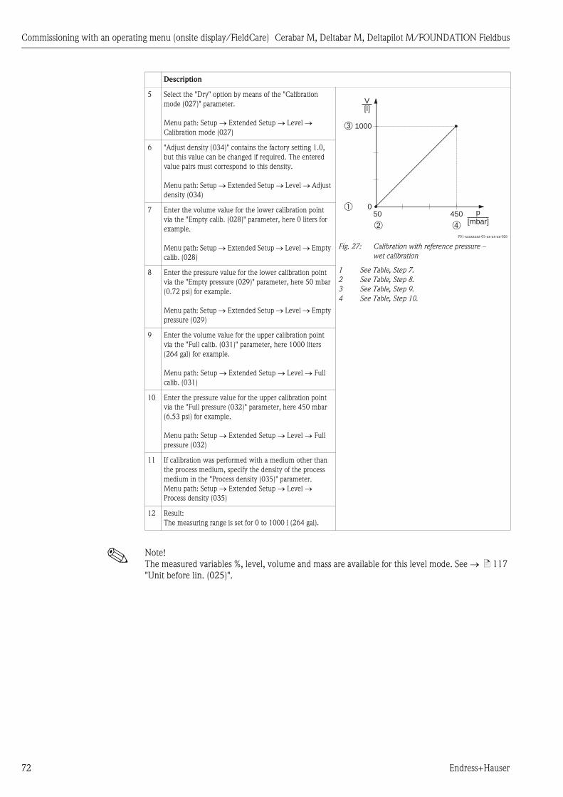
Commissioning with an operating menu (onsite display/FieldCare) Cerabar M, Deltabar M, Deltapilot M/FOUNDATION Fieldbus
72 Endress+Hauser
! Note!
The measured variables %, level, volume and mass are available for this level mode. See ä 117
"Unit before lin. (025)".
5 Select the "Dry" option by means of the "Calibration
mode (027)" parameter.
Menu path: Setup Extended Setup Level
Calibration mode (027)
P01-xxxxxxxx-05-xx-xx-xx-026
Fig. 27: Calibration with reference pressure –
wet calibration
1 See Table, Step 7.
2 See Table, Step 8.
3 See Table, Step 9.
4 See Table, Step 10.
6 "Adjust density (034)" contains the factory setting 1.0,
but this value can be changed if required. The entered
value pairs must correspond to this density.
Menu path: Setup Extended Setup Level Adjust
density (034)
7 Enter the volume value for the lower calibration point
via the "Empty calib. (028)" parameter, here 0 liters for
example.
Menu path: Setup Extended Setup Level Empty
calib. (028)
8 Enter the pressure value for the lower calibration point
via the "Empty pressure (029)" parameter, here 50 mbar
(0.72 psi) for example.
Menu path: Setup Extended Setup Level Empty
pressure (029)
9 Enter the volume value for the upper calibration point
via the "Full calib. (031)" parameter, here 1000 liters
(264 gal) for example.
Menu path: Setup Extended Setup Level Full
calib. (031)
10 Enter the pressure value for the upper calibration point
via the "Full pressure (032)" parameter, here 450 mbar
(6.53 psi) for example.
Menu path: Setup Extended Setup Level Full
pressure (032)
11 If calibration was performed with a medium other than
the process medium, specify the density of the process
medium in the "Process density (035)" parameter.
Menu path: Setup Extended Setup Level
Process density (035)
12 Result:
The measuring range is set for 0 to 1000 l (264 gal).
Description
1000
0
V[l]
50 450 p[mbar]
➀
➁
➂
➃

Cerabar M, Deltabar M, Deltapilot M/FOUNDATION Fieldbus Commissioning with an operating menu (onsite display/FieldCare)
Endress+Hauser 73
7.4.5 "In height" level selection
Calibration without reference pressure (dry calibration)
Example:
In this example, the volume in a tank should be measured in liters. The maximum volume of
1000 liters (264 gal) corresponds to a level of 4.5 m (14.8 ft). The minimum volume of 0 liters
corresponds to a level of 0.5 m (1.6 ft) since the device is mounted below the start of the level
measuring range.
Prerequisite:
• The measured variable is in direct proportion to the pressure.
• This is a theoretical calibration i.e. the height and volume values for the lower and upper
calibration point must be known.
! Note!
• The values entered for "Empty calib. (028)/Full calib. (031)", "Empty height (030)/Full height
(033)" must be at least 1% apart. The value will be rejected, and a warning message displayed, if
the values are too close together. Further limit values are not checked; i.e. the values entered
must be appropriate for the sensor and the measuring task so that the measuring device can
measure correctly.
• Due to the orientation of the device, there may be pressure shifts in the measured value, i.e. when
the container is empty or partly filled, the measured value is not zero. For information on how to
perform position adjustment, see ä 67, "Pos. zero adjust".
Description
1 Select the "Level" measuring mode via the "Measuring
mode (005)" parameter.
Menu path: Setup Measuring mode (005)
P01-Mxxxxxxx-19-xx-xx-xx-007
Fig. 28: Calibration without reference pressure –
dry calibration
1 See Table, Step 7.
2 See Table, Steps 8 and 9.
3 See Table, Steps 10 and 11.
2 Select a pressure unit via the "Press. eng. unit (125)"
parameter, here "mbar" for example.
Menu path: Setup Press. eng. unit (125)
3 Select the "In height" level mode via the "Level selection
(024)" parameter.
Menu path: Setup Extended Setup Level Level
selection (024)
4 Select a volume unit via the "Unit before lin. (025)"
parameter, here "l" (liter) for example.
Menu path: Setup Extended Setup Level Unit
before lin. (025)
5 Select a level unit by means of the "Height unit (026)"
parameter, here "m" for example.
Menu path: Setup Extended Setup Level Height
unit (026)
6 Select the "Dry" option by means of the "Calibration
mode (027)" parameter.
Menu path: Setup Extended Setup Level
Calibration mode (027)
7 Enter the density of the medium via the "Adjust density
(034)" parameter, here "1 g/cm3" (1 SGU) for example.
Menu path: Setup Extended Setup Level Adjust
density (034)
1000 l
0,5 m
4,5 m
0 l
� = 1 gcm3
1
3
2
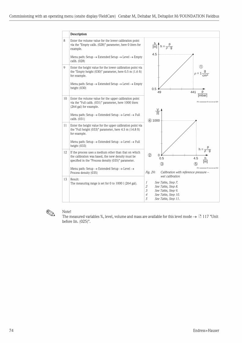
Commissioning with an operating menu (onsite display/FieldCare) Cerabar M, Deltabar M, Deltapilot M/FOUNDATION Fieldbus
74 Endress+Hauser
! Note!
The measured variables %, level, volume and mass are available for this level mode ä 117 "Unit
before lin. (025)".
8 Enter the volume value for the lower calibration point
via the "Empty calib. (028)" parameter, here 0 liters for
example.
Menu path: Setup Extended Setup Level Empty
calib. (028)
P01-xxxxxxxx-05-xx-xx-xx-029
P01-xxxxxxxx-05-xx-xx-xx-032
Fig. 29: Calibration with reference pressure –
wet calibration
1 See Table, Step 7.
2 See Table, Step 8.
3 See Table, Step 9.
4 See Table, Step 10.
5 See Table, Step 11.
9 Enter the height value for the lower calibration point via
the "Empty height (030)" parameter, here 0.5 m (1.6 ft)
for example.
Menu path: Setup Extended Setup Level Empty
height (030)
10 Enter the volume value for the upper calibration point
via the "Full calib. (031)" parameter, here 1000 liters
(264 gal) for example.
Menu path: Setup Extended Setup Level Full
calib. (031)
11 Enter the height value for the upper calibration point via
the "Full height (033)" parameter, here 4.5 m (14.8 ft)
for example.
Menu path: Setup Extended Setup Level Full
height (033)
12 If the process uses a medium other than that on which
the calibration was based, the new density must be
specified in the "Process density (035)" parameter.
Menu path: Setup Extended Setup Level
Process density (035)
13 Result:
The measuring range is set for 0 to 1000 l (264 gal).
Description
4.5
0.5
h[m]
49 441 p[mbar]
h =p
� · g
� = 1g
cm3
➀
1000
0
V[l]
0.5 4.5➁
➂
h =p
ρ · g
h[m]
➃
➄
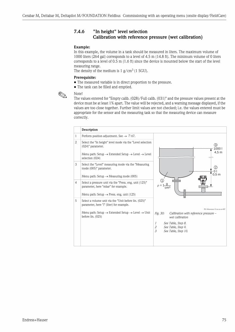
Cerabar M, Deltabar M, Deltapilot M/FOUNDATION Fieldbus Commissioning with an operating menu (onsite display/FieldCare)
Endress+Hauser 75
7.4.6 "In height" level selection
Calibration with reference pressure (wet calibration)
Example:
In this example, the volume in a tank should be measured in liters. The maximum volume of
1000 liters (264 gal) corresponds to a level of 4.5 m (14.8 ft). The minimum volume of 0 liters
corresponds to a level of 0.5 m (1.6 ft) since the device is mounted below the start of the level
measuring range.
The density of the medium is 1 g/cm3 (1 SGU).
Prerequisite:
• The measured variable is in direct proportion to the pressure.
• The tank can be filled and emptied.
! Note!
The values entered for "Empty calib. (028)/Full calib. (031)" and the pressure values present at the
device must be at least 1% apart. The value will be rejected, and a warning message displayed, if the
values are too close together. Further limit values are not checked; i.e. the values entered must be
appropriate for the sensor and the measuring task so that the measuring device can measure
correctly.
Description
1 Perform position adjustment. See ä 67.
P01-Mxxxxxxx-19-xx-xx-xx-007
Fig. 30: Calibration with reference pressure –
wet calibration
1 See Table, Step 8.
2 See Table, Step 9.
3 See Table, Step 10.
2 Select the "In height" level mode via the "Level selection
(024)" parameter.
Menu path: Setup Extended Setup Level Level
selection (024)
3 Select the "Level" measuring mode via the "Measuring
mode (005)" parameter.
Menu path: Setup Measuring mode (005)
4 Select a pressure unit via the "Press. eng. unit (125)"
parameter, here "mbar" for example.
Menu path: Setup Press. eng. unit (125)
5 Select a volume unit via the "Unit before lin. (025)"
parameter, here "l" (liter) for example.
Menu path: Setup Extended Setup Level Unit
before lin. (025)
1000 l
0,5 m
4,5 m
0 l
� = 1 gcm3
1
3
2
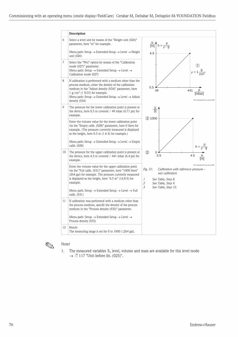
Commissioning with an operating menu (onsite display/FieldCare) Cerabar M, Deltabar M, Deltapilot M/FOUNDATION Fieldbus
76 Endress+Hauser
! Note!
1. The measured variables %, level, volume and mass are available for this level mode
ä 117 "Unit before lin. (025)".
6 Select a level unit by means of the "Height unit (026)"
parameter, here "m" for example.
Menu path: Setup Extended Setup Level Height
unit (026)
P01-xxxxxxxx-05-xx-xx-xx-029
P01-xxxxxxxx-05-xx-xx-xx-001
Fig. 31: Calibration with reference pressure –
wet calibration
1 See Table, Step 8.
2 See Table, Step 9.
3 See Table, Step 10.
7 Select the "Wet" option by means of the "Calibration
mode (027)" parameter.
Menu path: Setup Extended Setup Level
Calibration mode (027)
8 If calibration is performed with a medium other than the
process medium, enter the density of the calibration
medium in the "Adjust density (034)" parameter, here
1 g/cm3 (1 SGU) for example.
Menu path: Setup Extended Setup Level Adjust
density (034)
9 The pressure for the lower calibration point is present at
the device, here 0.5 m covered / 49 mbar (0.71 psi) for
example.
Enter the volume value for the lower calibration point
via the "Empty calib. (028)" parameter, here 0 liters for
example. (The pressure currently measured is displayed
as the height, here 0.5 m (1.6 ft) for example.)
Menu path: Setup Extended Setup Level Empty
calib. (028)
10 The pressure for the upper calibration point is present at
the device, here 4.5 m covered / 441 mbar (6.4 psi) for
example.
Enter the volume value for the upper calibration point
via the "Full calib. (031)" parameter, here "1000 liters"
(264 gal) for example. The pressure currently measured
is displayed as the height, here "4.5 m" (14.8 ft) for
example.
Menu path: Setup Extended Setup Level Full
calib. (031)
11 If calibration was performed with a medium other than
the process medium, specify the density of the process
medium in the "Process density (035)" parameter.
Menu path: Setup Extended Setup Level
Process density (035)
12 Result:
The measuring range is set for 0 to 1000 l (264 gal).
Description
4.5
0.5
h[m]
49 441 p[mbar]
h =p
� · g
� = 1g
cm3
➀
1000
0
V[l]
0.5 4.5➁
➂
h =p
� · g
h[m]
Cerabar M, Deltabar M, Deltapilot M/FOUNDATION Fieldbus Commissioning with an operating menu (onsite display/FieldCare)
Endress+Hauser 77
7.4.7 Required parameters for Level measuring mode
Parameter name Description
Level selection (024) ä 117
Unit before lin. (025) ä 117
Height unit (026) ä 117
Calibration mode (027) ä 117
Empty calib. (028) ä 118
Empty pressure (029) ä 118
Empty height (030) ä 118
Full calib. (031) ä 118
Full pressure (032) ä 118
Full height (033) ä 118
Density unit (127) ä 118
Adjust density (034) ä 119
Process density (035) ä 119
Level before lin. (019) ä 119

Commissioning with an operating menu (onsite display/FieldCare) Cerabar M, Deltabar M, Deltapilot M/FOUNDATION Fieldbus
78 Endress+Hauser
7.5 Linearization
7.5.1 Manual entry of the linearization table via onsite display
Example:
In this example, the volume in a tank with a conical outlet should be measured in m3.
Prerequisite:
• This is a theoretical calibration, i.e. the points for the linearization table are known.
• The "Level" operating mode has been selected.
• A level calibration in m has been performed.
! Note!
For a description of the parameters mentioned, Chap. 7.11 "Description of parameters".
Description
1 Select the "Manual entry" option via the "Lin. mode
(037)" parameter.
Menu path: Setup Extended Setup Linearization
Lin. mode (037)
P01-Mxxxxxxx-19-xx-xx-xx-006
P01-Mxxxxxxx-05-xx-xx-xx-015
2 Select a unit via the "Unit after lin. (038)" parameter,
e.g. m3.
Menu path: Setup Extended Setup Linearization
Unit after lin. (038)
3 Enter the number of the point in the table via the "Line
numb. (039)" parameter.
Menu path: Setup Extended Setup Linearization
Line numb. (039)
The level is entered via the "X-value (040) (manual
entry)" parameter, here 0 m for example. Confirm your
entry.
Menu path: Setup Extended Setup Linearization
X-value (040) (manual entry)
Using the "Y-value (041) (manual entry/in semi-auto.
entry)" parameter, enter the associated volume value,
here 0 m3 for example, and confirm the value.
Menu path: Setup Extended Setup Linearization
Y-value (041) (manual entry/in semi-auto. entry)
3.5
00 3
V[m ]3
h[m]
3.5
00 3.0
V[m ]3
h[m]

Cerabar M, Deltabar M, Deltapilot M/FOUNDATION Fieldbus Commissioning with an operating menu (onsite display/FieldCare)
Endress+Hauser 79
! Note!
Error message F510 "Linearization" and status signal "failure" appears as long as the table is being
entered and until the table is activated.
4 To enter another point in the table, select the "Next
point" option via the "Edit table (042)" parameter.
Enter the next point as explained in Step 3.
Menu path: Setup Extended Setup Linearization
Edit table (042)
5 Once all the points have been entered in the table, select
the "Activate table" option via the "Lin. mode"
parameter.Lin. mode (037)
Menu path: Setup Extended Setup Linearization
Lin. mode (037)
6 Result:
The measured value after linearization is displayed.
Description
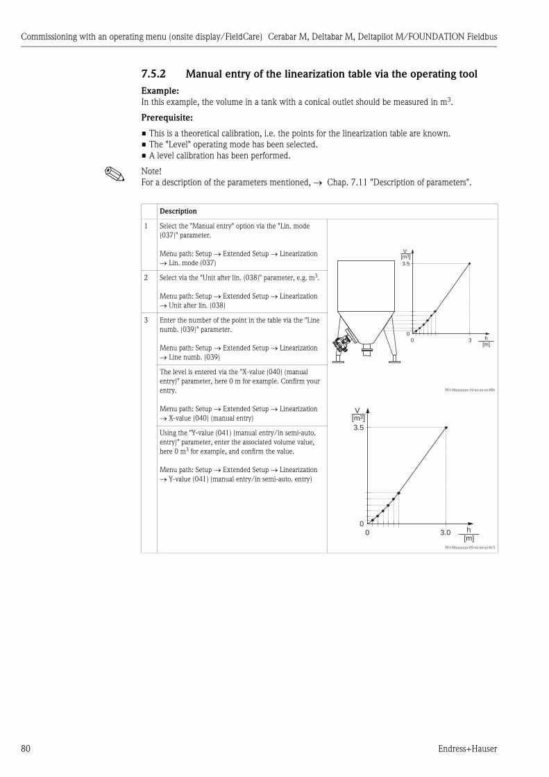
Commissioning with an operating menu (onsite display/FieldCare) Cerabar M, Deltabar M, Deltapilot M/FOUNDATION Fieldbus
80 Endress+Hauser
7.5.2 Manual entry of the linearization table via the operating tool
Example:
In this example, the volume in a tank with a conical outlet should be measured in m3.
Prerequisite:
• This is a theoretical calibration, i.e. the points for the linearization table are known.
• The "Level" operating mode has been selected.
• A level calibration has been performed.
! Note!
For a description of the parameters mentioned, Chap. 7.11 "Description of parameters".
Description
1 Select the "Manual entry" option via the "Lin. mode
(037)" parameter.
Menu path: Setup Extended Setup Linearization
Lin. mode (037)
P01-Mxxxxxxx-19-xx-xx-xx-006
P01-Mxxxxxxx-05-xx-xx-xx-015
2 Select via the "Unit after lin. (038)" parameter, e.g. m3.
Menu path: Setup Extended Setup Linearization
Unit after lin. (038)
3 Enter the number of the point in the table via the "Line
numb. (039)" parameter.
Menu path: Setup Extended Setup Linearization
Line numb. (039)
The level is entered via the "X-value (040) (manual
entry)" parameter, here 0 m for example. Confirm your
entry.
Menu path: Setup Extended Setup Linearization
X-value (040) (manual entry)
Using the "Y-value (041) (manual entry/in semi-auto.
entry)" parameter, enter the associated volume value,
here 0 m3 for example, and confirm the value.
Menu path: Setup Extended Setup Linearization
Y-value (041) (manual entry/in semi-auto. entry)
3.5
00 3
V[m ]3
h[m]
3.5
00 3.0
V[m ]3
h[m]
Cerabar M, Deltabar M, Deltapilot M/FOUNDATION Fieldbus Commissioning with an operating menu (onsite display/FieldCare)
Endress+Hauser 81
! Note!
Error message F510 "Linearization" and alarm current appears as long as the table is being entered
and until the table is activated.
4 To enter another point in the table, select the "Next
point" option via the "Edit table (042)" parameter.
Enter the next point as explained in Step 3.
Menu path: Setup Extended Setup Linearization
Edit table (042)
5 Once all the points have been entered in the table, select
the "Activate table" option via the "Lin. mode"
parameter.Lin. mode (037)
Menu path: Setup Extended Setup Linearization
Lin. mode (037)
6 Result:
The measured value after linearization is displayed.
Description

Commissioning with an operating menu (onsite display/FieldCare) Cerabar M, Deltabar M, Deltapilot M/FOUNDATION Fieldbus
82 Endress+Hauser
7.5.3 Semi-automatic entry of the linearization table
Example:
In this example, the volume in a tank with a conical outlet should be measured in m3.
Prerequisite:
• The tank can be filled or emptied. The linearization characteristic must rise continuously.
• The "Level" operating mode has been selected.
! Note!
For a description of the parameters mentioned Chap. 7.11 "Description of parameters".
! Note!
Error message F510 "Linearization" and status signal "failure" appears as long as the table is being
entered and until the table is activated.
Description
1 Select the "Semi-auto. entry" option via the "Lin. mode
(037)" parameter.
Menu path: Setup Extended Setup Linearization
Lin. mode (037)
P01-Mxxxxxxx-19-xx-xx-xx-006
P01-Mxxxxxxx-05-xx-xx-xx-015
Fig. 32: Semi-automatic entry of the linearization
table
2 Select the volume unit/mass unit via the "Unit after lin.
(038)" parameter, e.g. m3.
Menu path: Setup Extended Setup Linearization
Unit after lin. (038)
3 Fill the tank to the height of the 1st point.
4 Enter the number of the point in the table via the "Line
numb. (039)" parameter.
Menu path: Setup Extended Setup Linearization
Line numb. (039)
The actual level is displayed via the "X-value (040)
(manual entry)" parameter.
Menu path: Setup Extended Setup Linearization
X-value (040) (manual entry)
Using the "Y-value (041) (manual entry/in semi-auto.
entry)" parameter, enter the associated volume value,
here 0 m3 for example, and confirm the value.
Menu path: Setup Extended Setup Linearization
Y-value (041) (manual entry/in semi-auto. entry)
5 To enter another point in the table, select the "Next
point" option via the "Edit table (042)" parameter.
Enter the next point as explained in Step 4.
Menu path: Setup Extended Setup Linearization
Edit table (042)
6 Once all the points have been entered in the table, select
the "Activate table" option via the "Lin. mode (037)"
parameter.
Menu path: Setup Extended Setup Linearization
Lin. mode (037)
7 Result:
The measured value after linearization is displayed.
3.5
00 3
V[m ]3
h[m]
3.5
00 3.0
V[m ]3
h[m]

Cerabar M, Deltabar M, Deltapilot M/FOUNDATION Fieldbus Commissioning with an operating menu (onsite display/FieldCare)
Endress+Hauser 83
7.5.4 Required parameters for linearization
Parameter name Description
Lin. mode (037) ä 119
Unit after lin. (038) ä 119
Line numb. (039) ä 119
X-value (040) (manual entry) ä 120
Y-value (041) (manual entry/in semi-auto. entry) ä 120
Edit table (042) ä 120
Tank description (173) ä 120
Tank content (043) ä 120

Commissioning with an operating menu (onsite display/FieldCare) Cerabar M, Deltabar M, Deltapilot M/FOUNDATION Fieldbus
84 Endress+Hauser
7.6 Pressure measurement
7.6.1 Calibration without reference pressure (dry calibration)
! Note!
Calibration is possible only using FieldCare.
Example:
In this example, a device with a 400 mbar (6 psi) sensor is configured for the 0 to +300 mbar
(4.35 psi) measuring range, i.e. 0 mbar and 300 mbar (4.35 psi) are assigned.
Prerequisite:
This is a theoretical calibration, i.e. the pressure values for the lower and upper range are known.
! Note!
Due to the orientation of the device, there may be pressure shifts in the measured value, i.e. the
measured value is not zero in a pressureless condition. For information on how to perform position
adjustment, see ä 67.
7.6.2 Required parameters for Pressure measuring mode
Description
1 Select the "Pressure" measuring mode via the
"Measuring mode (005)" parameter.
Menu path: Setup Measuring mode (005)
2 Select a pressure unit via the "Scale in. Press. eng. unit"
element, here "mbar" for example.
Menu path: Setup Scale in. Press. eng. unit
3 Enter a pressure value of 0 mbar via the "Scale in. Set
LRV" element.
Menu path: Expert Communication Pressure
Transducer Block Scale in. Set LRV
4 Enter a pressure value of 300 mbar (4.35 psi) via the
"Scale in. Set LRV" element.
Menu path: Expert Communication Pressure
Transducer Block Scale in. Set LRV
5 Result:
The measuring range is configured for 0 to +300 mbar
(4.35 psi).
Parameter name Description
Measuring mode (005) ä 113
Switch P1/P2 (163) ä 115
High-pressure side (006) (Deltabar) ä 115
Press. eng. unit (125) ä 114
Corrected press. (172) ä 116
Pos. zero adjust (007) (Deltabar M and gauge pressure sensor) ä 114
Damping switch (164) ä 114
Damping value (017) ä 114
Pressure af. damp (111) ä 116

Cerabar M, Deltabar M, Deltapilot M/FOUNDATION Fieldbus Commissioning with an operating menu (onsite display/FieldCare)
Endress+Hauser 85
7.7 Differential pressure measurement (Deltabar M)
7.7.1 Preparatory steps
! Note!
• Before calibrating the device, the impulse piping must be cleaned and filled with medium.
See the following table.
Valves Meaning Preferred installation
1 Close 3.
P01-PMD55xxx-11-xx-xx-xx-013
Above: preferred installation for gases
Below: preferred installation for liquids
I Deltabar M
II Three-valve manifold
III Separator
1, 5 Drain valves
2, 4 Inlet valves
3 Equalizing valve
6, 7 Vent valves on Deltabar M
A, B Shut-off valve
2 Fill measuring system with medium.
Open A, B, 2, 4. Medium flows in.
3 Clean impulse piping if necessary:1)
– by blowing out with compressed air in the case of gases
– by rinsing out in the case of liquids.
1) for arrangement with 5 valves
Close 2 and 4. Block off device.
Open 1 and 5. Blow out/rinse out impulse
piping.
Close 1 and 5. Close valves after cleaning.
4 Vent device.
Open 2 and 4. Introduce medium.
Close 4. Close low-pressure side.
Open 3. Balance positive and low-
pressure side.
Open 6 and 7 briefly, then
close them again.
Fill device completely with
medium and remove air.
5 Set measuring point in operation.
Close 3. Shut off high-pressure side
from low-pressure side.
Open 4. Connect low-pressure side.
Now
– 1, 3, 5, 6 and 7 are closed.
– 2 and 4 are open.
– A and B open (if present).
6 Carry out calibration if necessary. See also page 86.
I
II
+ –
–P2
+P1
6 7
–P2
+P1
6 7
3
2 4
A B
A B
+
1 52 4
3II
I
IIIIII

Commissioning with an operating menu (onsite display/FieldCare) Cerabar M, Deltabar M, Deltapilot M/FOUNDATION Fieldbus
86 Endress+Hauser
7.7.2 Required parameters for differential pressure via Pressure
measuring mode
Parameter name Description
Measuring mode (005) ä 113
Switch P1/P2 (163) ä 115
High-pressure side (006) (Deltabar) ä 115
Press. eng. unit (125) ä 114
Corrected press. (172) ä 116
Pos. zero adjust (007) (Deltabar M and gauge pressure sensor) ä 114
Calib. offset (192) / (008) (absolute pressure sensor) ä 114
Damping switch (164) ä 114
Damping value (017) ä 114
Pressure af. damp (111) ä 116
Cerabar M, Deltabar M, Deltapilot M/FOUNDATION Fieldbus Commissioning with an operating menu (onsite display/FieldCare)
Endress+Hauser 87
7.8 Flow measurement (Deltabar M)
7.8.1 Information on flow measurement
In the "Flow" measuring mode, the device determines a volume or mass flow value from the
differential pressure measured. The differential pressure is generated by means of primary elements
such as pitot tubes or orifice plates and depends on the volume or mass flow. Four flow types are
available: volume flow, norm volume flow (European norm conditions), standard volume flow
(American standard conditions), mass flow and flow in %.
In addition, the Deltabar M software is equipped with two totalizers as standard. The totalizers add
up the volume or the mass flow. The counting function and the unit can be set separately for both
totalizers. The first totalizer (totalizer 1) can be reset to zero at any time while the second
(totalizer 2) totalizes the flow from commissioning onwards and cannot be reset.
! Note!
The totalizers are not available for the "Flow in %" flow type.

Commissioning with an operating menu (onsite display/FieldCare) Cerabar M, Deltabar M, Deltapilot M/FOUNDATION Fieldbus
88 Endress+Hauser
7.8.2 Preparatory steps
! Note!
• Before calibrating the Deltabar M, the impulse piping must be cleaned and filled with medium.
See the following table.
Valves Meaning Preferred installation
1 Close 3.
P01-PMD55xxx-11-xx-xx-xx-013
Above: preferred installation for gases
Below: preferred installation for liquids
I Deltabar M
II Three-valve manifold
III Separator
1, 5 Drain valves
2, 4 Inlet valves
3 Equalizing valve
6, 7 Vent valves on Deltabar M
A, B Shut-off valves
2 Fill measuring system with medium.
Open A, B, 2, 4. Medium flows in.
3 Clean impulse piping if necessary1):
– by blowing out with compressed air in the case of gases
– by rinsing out in the case of liquids.
1) for arrangement with 5 valves
Close 2 and 4. Block off device.
Open 1 and 5. Blow out/rinse out impulse
piping.
Close 1 and 5. Close valves after cleaning.
4 Vent device.
Open 2 and 4. Introduce medium.
Close 4. Close low-pressure side.
Open 3. Balance positive and low-
pressure side.
Open 6 and 7 briefly, then
close them again.
Fill device completely with
medium and remove air.
5 Carry out position zero adjustment ( ä 67) if the following
conditions are met. If the conditions are not met, then do not
carry out the pos. zero adjustment until after step 6.
Conditions:
– The process cannot be blocked off.
– The tapping points (A and B) are at the same geodetic
height.
6 Set measuring point in operation.
Close 3. Shut off high-pressure side
from low-pressure side.
Open 4. Connect low-pressure side.
Now
– 1, 3, 5, 6 and 7 are closed.
– 2 and 4 are open.
– A and B open (if present).
7 Carry out position zero adjustment ( ä 67) if the flow can
be blocked off. In this case, step 5 is not applicable.
8 Carry out calibration. See page 89, Chap. 7.8.3.
I
II
+ –
–P2
+P1
6 7
–P2
+P1
6 7
3
2 4
A B
A B
+
1 52 4
3II
I
IIIIII
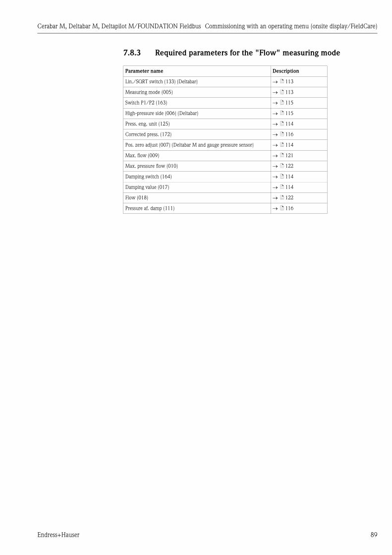
Cerabar M, Deltabar M, Deltapilot M/FOUNDATION Fieldbus Commissioning with an operating menu (onsite display/FieldCare)
Endress+Hauser 89
7.8.3 Required parameters for the "Flow" measuring mode
Parameter name Description
Lin./SQRT switch (133) (Deltabar) ä 113
Measuring mode (005) ä 113
Switch P1/P2 (163) ä 115
High-pressure side (006) (Deltabar) ä 115
Press. eng. unit (125) ä 114
Corrected press. (172) ä 116
Pos. zero adjust (007) (Deltabar M and gauge pressure sensor) ä 114
Max. flow (009) ä 121
Max. pressure flow (010) ä 122
Damping switch (164) ä 114
Damping value (017) ä 114
Flow (018) ä 122
Pressure af. damp (111) ä 116
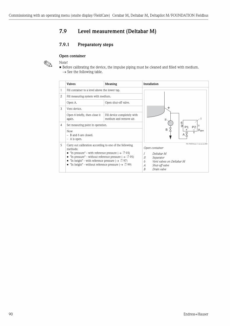
Commissioning with an operating menu (onsite display/FieldCare) Cerabar M, Deltabar M, Deltapilot M/FOUNDATION Fieldbus
90 Endress+Hauser
7.9 Level measurement (Deltabar M)
7.9.1 Preparatory steps
Open container
! Note!
• Before calibrating the device, the impulse piping must be cleaned and filled with medium.
See the following table.
Valves Meaning Installation
1 Fill container to a level above the lower tap.
P01-PMD55xxx-11-xx-xx-xx-008
Open container
I Deltabar M
II Separator
6 Vent valves on Deltabar M
A Shut-off valve
B Drain valve
2 Fill measuring system with medium.
Open A. Open shut-off valve.
3 Vent device.
Open 6 briefly, then close it
again.
Fill device completely with
medium and remove air.
4 Set measuring point in operation.
Now
– B and 6 are closed.
– A is open.
5 Carry out calibration according to one of the following
methods:
• "In pressure" - with reference pressure ( ä 93)
• "In pressure" - without reference pressure ( ä 95)
• "In height" - with reference pressure ( ä 97)
• "In height" - without reference pressure ( ä 99)
+
A
B
II I
patm–P2
+P1
6

Cerabar M, Deltabar M, Deltapilot M/FOUNDATION Fieldbus Commissioning with an operating menu (onsite display/FieldCare)
Endress+Hauser 91
Closed container
! Note!
• Before calibrating the device, the impulse piping must be cleaned and filled with medium.
See the following table.
Valves Meaning Installation
1 Fill container to a level above the lower tap.
P01-PMD55xxx-11-xx-xx-xx-009
Closed container
I Deltabar M
II Three-valve manifold
III Separator
1, 5 Drain valves
2, 4 Inlet valves
3 Equalizing valve
6, 7 Vent valve on Deltabar M
A, B Shut-off valve
2 Fill measuring system with medium.
Close 3. Shut off high-pressure side
from low-pressure side.
Open A and B. Open shut-off valves.
3 Vent high-pressure side (empty low-pressure side if
necessary).
Open 2 and 4. Introduce medium on high-
pressure side.
Open 6 and 7 briefly, then
close them again.
Fill high-pressure side
completely with medium and
remove air.
4 Set measuring point in operation.
Now
– 3, 6 and 7 are closed.
– 2, 4, A and B are open.
5 Carry out calibration according to one of the following
methods:
• "In pressure" - with reference pressure ( ä 93)
• "In pressure" - without reference pressure ( ä 95)
• "In height" - with reference pressure ( ä 97)
• "In height" - without reference pressure ( ä 99)
+
–
A
B
3
2 4
1 5
II
I
IIIIII
–P2
+P1
6 7

Commissioning with an operating menu (onsite display/FieldCare) Cerabar M, Deltabar M, Deltapilot M/FOUNDATION Fieldbus
92 Endress+Hauser
Closed container with superimposed steam
! Note!
• Before calibrating the device, the impulse piping must be cleaned and filled with medium.
See the following table.
Valves Meaning Installation
1 Fill container to a level above the lower tap.
P01-PMD55xxx-11-xx-xx-xx-010
Closed container with superimposed steam
I Deltabar M
II Three-valve manifold
III Separator
1, 5 Drain valves
2, 4 Inlet valves
3 Equalizing valve
6, 7 Vent valves on Deltabar M
A, B Shut-off valves
2 Fill measuring system with medium.
Open A and B. Open shut-off valves.
Fill the negative impulse piping to the level of the condensate
trap.
3 Vent device.
Open 2 and 4. Introduce medium.
Close 4. Close low-pressure side.
Open 3. Balance positive and low-
pressure side.
Open 6 and 7 briefly, then
close them again.
Fill device completely with
medium and remove air.
4 Set measuring point in operation.
Close 3. Shut off high-pressure side
from low-pressure side.
Open 4. Connect low-pressure side.
Now
– 3, 6 and 7 are closed.
– 2, 4, A and B are open.
5 Carry out calibration according to one of the following
methods:
• "In pressure" - with reference pressure ( ä 93)
• "In pressure" - without reference pressure ( ä 95)
• "In height" - with reference pressure ( ä 97)
• "In height" - without reference pressure ( ä 99)
+
–
A
B
3
2 4
1 5
II
I
IIIIII
–P2
+P1
6 7

Cerabar M, Deltabar M, Deltapilot M/FOUNDATION Fieldbus Commissioning with an operating menu (onsite display/FieldCare)
Endress+Hauser 93
7.9.2 "In pressure" level selection
Calibration with reference pressure (wet calibration)
Example:
In this example, the level in a tank should be measured in "m". The maximum level is 3 m (9.8 ft).
The pressure range is due to the filling height and the density.
Prerequisite:
• The measured variable is in direct proportion to the pressure.
• The tank can be filled and emptied.
! Note!
The values entered for "Empty calib. (028)/Full calib. (031)" and the pressures present at the device
must be at least 1% apart. The value will be rejected, and a warning message displayed, if the values
are too close together. Further limit values are not checked; i.e. the values entered must be
appropriate for the sensor and the measuring task so that the measuring device can measure
correctly.
Description
1 Perform "position adjustment" ä 67.
2 Select the "Level" measuring mode via the "Measuring
mode (005)" parameter.
Menu path: Setup Measuring mode (005)
3 Select a pressure unit by means of the "Press. eng. unit
(125)" parameter, here "mbar" for example.
Menu path: Setup Press. eng. unit (125)
4 Select the "In pressure" level mode by means of the
"Level selection (024)" parameter.
Menu path: Setup Extended Setup Level Level
selection (024)

Commissioning with an operating menu (onsite display/FieldCare) Cerabar M, Deltabar M, Deltapilot M/FOUNDATION Fieldbus
94 Endress+Hauser
! Note!
The measured variables %, level, volume and mass are available for this level mode. See ä 117
"Unit before lin. (025)".
5 Select a level unit by means of the "Unit before lin.
(025)" parameter, here "m" for example.
Menu path: Setup Extended Setup Level Unit
before lin. (025)
P01-xxxxxxxx-05-xx-xx-xx-011
Fig. 33: Calibration with reference pressure –
wet calibration
1 See Table, Step 7.
2 See Table, Step 8.
6 Select the "Wet" option by means of the "Calibration
mode (027)" parameter.
Menu path: Setup Extended Setup Level
Calibration mode (027)
7 The pressure for the lower calibration point is present at
the device, here 0 mbar for example.
Select the "Empty calib. (028)" parameter.
Menu path: Setup Extended Setup Level Empty
calib. (028)
Enter the level value, here 0 m for example. The
pressure value present is assigned to the lower level
value by confirming the value.
8 The pressure for the upper calibration point is present at
the device, here 300 mbar (4.35 psi) for example.
Select the "Full calib. (031)" parameter.
Menu path: Setup Extended Setup Level Full
calib. (031)
Enter the level value, here 3 m (9.8 ft) for example. The
pressure value present is assigned to the upper level
value by confirming the value.
9 If calibration is performed with a medium other than the
process medium, enter the density of the calibration
medium in "Adjust density (034)".
Menu path: Setup Extended Setup Level Adjust
density (034)
10 If calibration was performed with a medium other than
the process medium, specify the density of the process
medium in the "Process density (035)" parameter.
Menu path: Setup Extended Setup Level
Process density (035)
11 Result:
The measuring range is set for 0 to 3 m (9.8 ft).
Description
3
0
h[m]
0 300 p[mbar]
➀
➁

Cerabar M, Deltabar M, Deltapilot M/FOUNDATION Fieldbus Commissioning with an operating menu (onsite display/FieldCare)
Endress+Hauser 95
7.9.3 "In pressure" level selection
Calibration without reference pressure (dry calibration)
Example:
In this example, the volume in a tank should be measured in liters. The maximum volume of
1000 liters (264 gal) corresponds to a pressure of 450 mbar (6.53 psi). The minimum volume of
0 liters corresponds to a pressure of 50 mbar (0.72 psi) since the device is mounted below the start
of the level measuring range.
Prerequisite:
• The measured variable is in direct proportion to the pressure.
• This is a theoretical calibration i.e. the pressure and volume values for the lower and upper
calibration point must be known.
! Note!
• The values entered for "Empty calib. (028)/Full calib. (031)", "Empty pressure (029)/Full
pressure (032)" must be at least 1% apart. The value will be rejected, and a warning message
displayed, if the values are too close together. Further limit values are not checked; i.e. the values
entered must be appropriate for the sensor and the measuring task so that the measuring device
can measure correctly.
• Due to the orientation of the device, there may be pressure shifts in the measured value, i.e. when
the container is empty or partly filled, the measured value is not zero. For information on how to
perform position adjustment, see ä 67, "Pos. zero adjust".
Description
1 Select the "Level" measuring mode via the "Measuring
mode (005)" parameter.
Menu path: Setup Measuring mode (005)
2 Select a pressure unit by means of the "Press. eng. unit
(125)" parameter, here "mbar" for example.
Menu path: Setup Press. eng. unit (125)
3 Select the "In pressure" level mode by means of the
"Level selection (024)" parameter.
Menu path: Setup Extended Setup Level Level
selection (024)
4 Select a volume unit by means of the "Unit before lin.
(025)" parameter, here "l" (liter) for example.
Menu path: Setup Extended Setup Level Unit
before lin. (025)

Commissioning with an operating menu (onsite display/FieldCare) Cerabar M, Deltabar M, Deltapilot M/FOUNDATION Fieldbus
96 Endress+Hauser
! Note!
The measured variables %, level, volume and mass are available for this level mode. See ä 117
"Unit before lin. (025)".
5 Select the "Dry" option by means of the "Calibration
mode (027)" parameter.
Menu path: Setup Extended Setup Level
Calibration mode (027)
P01-xxxxxxxx-05-xx-xx-xx-026
Fig. 34: Calibration with reference pressure –
wet calibration
1 See Table, Step 7.
2 See Table, Step 8.
3 See Table, Step 9.
4 See Table, Step 10.
6 "Adjust density (034)" contains the factory setting 1.0,
but this value can be changed if required. The entered
value pairs must correspond to this density.
Menu path: Setup Extended Setup Level Adjust
density (034)
7 Enter the volume value for the lower calibration point
via the "Empty calib. (028)" parameter, here 0 liters for
example.
Menu path: Setup Extended Setup Level Empty
calib. (028)
8 Enter the pressure value for the lower calibration point
via the "Empty pressure (029)" parameter, here 50 mbar
(0.72 psi) for example.
Menu path: Setup Extended Setup Level Empty
pressure (029)
9 Enter the volume value for the upper calibration point
via the "Full calib. (031)" parameter, here 1000 liters
(264 gal) for example.
Menu path: Setup Extended Setup Level Full
calib. (031)
10 Enter the pressure value for the upper calibration point
via the "Full pressure (032)" parameter, here 450 mbar
(6.53 psi) for example.
Menu path: Setup Extended Setup Level Full
pressure (032)
11 If calibration was performed with a medium other than
the process medium, specify the density of the process
medium in the "Process density (035)" parameter.
Menu path: Setup Extended Setup Level
Process density (035)
12 Result:
The measuring range is set for 0 to 1000 l (264 gal).
Description
1000
0
V[l]
50 450 p[mbar]
➀
➁
➂
➃

Cerabar M, Deltabar M, Deltapilot M/FOUNDATION Fieldbus Commissioning with an operating menu (onsite display/FieldCare)
Endress+Hauser 97
7.9.4 "In height" level selection
Calibration without reference pressure (dry calibration)
Example:
In this example, the volume in a tank should be measured in liters. The maximum volume of
1000 liters (264 gal) corresponds to a level of 4.5 m (14.8 ft). The minimum volume of 0 liters
corresponds to a level of 0.5 m (1.6 ft) since the device is mounted below the start of the level
measuring range.
Prerequisite:
• The measured variable is in direct proportion to the pressure.
• This is a theoretical calibration i.e. the height and volume values for the lower and upper
calibration point must be known.
! Note!
• The values entered for "Empty calib. (028)/Full calib. (031)", "Empty height (030)/Full height
(033)" must be at least 1% apart. The value will be rejected, and a warning message displayed, if
the values are too close together. Further limit values are not checked; i.e. the values entered
must be appropriate for the sensor and the measuring task so that the measuring device can
measure correctly.
• Due to the orientation of the device, there may be pressure shifts in the measured value, i.e. when
the container is empty or partly filled, the measured value is not zero. For information on how to
perform position adjustment, see ä 67, "Pos. zero adjust".
Description
1 Select the "Level" measuring mode via the "Measuring
mode (005)" parameter.
Menu path: Setup Measuring mode (005)
2 Select a pressure unit via the "Press. eng. unit (125)"
parameter, here "mbar" for example.
Menu path: Setup Press. eng. unit (125)
3 Select the "In height" level mode via the "Level selection
(024)" parameter.
Menu path: Setup Extended Setup Level Level
selection (024)
4 Select a volume unit via the "Unit before lin. (025)"
parameter, here "l" (liter) for example.
Menu path: Setup Extended Setup Level Unit
before lin. (025)
5 Select a level unit by means of the "Height unit (026)"
parameter, here "m" for example.
Menu path: Setup Extended Setup Level Height
unit (026)
6 Select the "Dry" option by means of the "Calibration
mode (027)" parameter.
Menu path: Setup Extended Setup Level
Calibration mode (027)
7 Enter the density of the medium via the "Adjust density
(034)" parameter, here "1 g/cm3" (1 SGU) for example.
Menu path: Setup Extended Setup Level Adjust
density (034)

Commissioning with an operating menu (onsite display/FieldCare) Cerabar M, Deltabar M, Deltapilot M/FOUNDATION Fieldbus
98 Endress+Hauser
! Note!
The measured variables %, level, volume and mass are available for this level mode ä 117 "Unit
before lin. (025)".
8 Enter the volume value for the lower calibration point
via the "Empty calib. (028)" parameter, here 0 liters for
example.
Menu path: Setup Extended Setup Level Empty
calib. (028)
P01-xxxxxxxx-05-xx-xx-xx-029
P01-xxxxxxxx-05-xx-xx-xx-032
Fig. 35: Calibration with reference pressure –
wet calibration
1 See Table, Step 7.
2 See Table, Step 8.
3 See Table, Step 9.
4 See Table, Step 10.
5 See Table, Step 11.
9 Enter the height value for the lower calibration point via
the "Empty height (030)" parameter, here 0.5 m (1.6 ft)
for example.
Menu path: Setup Extended Setup Level Empty
height (030)
10 Enter the volume value for the upper calibration point
via the "Full calib. (031)" parameter, here 1000 liters
(264 gal) for example.
Menu path: Setup Extended Setup Level Full
calib. (031)
11 Enter the height value for the upper calibration point via
the "Full height (033)" parameter, here 4.5 m (14.8 ft)
for example.
Menu path: Setup Extended Setup Level Full
height (033)
12 If the process uses a medium other than that on which
the calibration was based, the new density must be
specified in the "Process density (035)" parameter.
Menu path: Setup Extended Setup Level
Process density (035)
13 Result:
The measuring range is set for 0 to 1000 l (264 gal).
Description
4.5
0.5
h[m]
49 441 p[mbar]
h =p
� · g
� = 1g
cm3
➀
1000
0
V[l]
0.5 4.5➁
➂
h =p
ρ · g
h[m]
➃
➄

Cerabar M, Deltabar M, Deltapilot M/FOUNDATION Fieldbus Commissioning with an operating menu (onsite display/FieldCare)
Endress+Hauser 99
7.9.5 "In height" level selection
Calibration with reference pressure (wet calibration)
Example:
In this example, the volume in a tank should be measured in liters. The maximum volume of
1000 liters (264 gal) corresponds to a level of 4.5 m (14.8 ft). The minimum volume of 0 liters
corresponds to a level of 0.5 m (1.6 ft) since the device is mounted below the start of the level
measuring range.
The density of the medium is 1 g/cm3 (1 SGU).
Prerequisite:
• The measured variable is in direct proportion to the pressure.
• The tank can be filled and emptied.
! Note!
The values entered for "Empty calib. (028)/Full calib. (031)" and the pressure values present at the
device must be at least 1% apart. The value will be rejected, and a warning message displayed, if the
values are too close together. Further limit values are not checked; i.e. the values entered must be
appropriate for the sensor and the measuring task so that the measuring device can measure
correctly.
Description
1 Perform position adjustment. See ä 67.
2 Select the "In height" level mode via the "Level selection
(024)" parameter.
Menu path: Setup Extended Setup Level Level
selection (024)
3 Select the "Level" measuring mode via the "Measuring
mode (005)" parameter.
Menu path: Setup Measuring mode (005)
4 Select a pressure unit via the "Press. eng. unit (125)"
parameter, here "mbar" for example.
Menu path: Setup Press. eng. unit (125)
5 Select a volume unit via the "Unit before lin. (025)"
parameter, here "l" (liter) for example.
Menu path: Setup Extended Setup Level Unit
before lin. (025)

Commissioning with an operating menu (onsite display/FieldCare) Cerabar M, Deltabar M, Deltapilot M/FOUNDATION Fieldbus
100 Endress+Hauser
! Note!
1. The measured variables %, level, volume and mass are available for this level mode
ä 117 "Unit before lin. (025)".
6 Select a level unit by means of the "Height unit (026)"
parameter, here "m" for example.
Menu path: Setup Extended Setup Level Height
unit (026)
P01-xxxxxxxx-05-xx-xx-xx-029
P01-xxxxxxxx-05-xx-xx-xx-001
Fig. 36: Calibration with reference pressure –
wet calibration
1 See Table, Step 8.
2 See Table, Step 9.
3 See Table, Step 10.
7 Select the "Wet" option by means of the "Calibration
mode (027)" parameter.
Menu path: Setup Extended Setup Level
Calibration mode (027)
8 If calibration is performed with a medium other than the
process medium, enter the density of the calibration
medium in the "Adjust density (034)" parameter, here
1 g/cm3 (1 SGU) for example.
Menu path: Setup Extended Setup Level Adjust
density (034)
9 The pressure for the lower calibration point is present at
the device, here 0.5 m covered / 49 mbar (0.71 psi) for
example.
Enter the volume value for the lower calibration point
via the "Empty calib. (028)" parameter, here 0 liters for
example. (The pressure currently measured is displayed
as the height, here 0.5 m (1.6 ft) for example.)
Menu path: Setup Extended Setup Level Empty
calib. (028)
10 The pressure for the upper calibration point is present at
the device, here 4.5 m covered / 441 mbar (6.4 psi) for
example.
Enter the volume value for the upper calibration point
via the "Full calib. (031)" parameter, here "1000 liters"
(264 gal) for example. The pressure currently measured
is displayed as the height, here "4.5 m" (14.8 ft) for
example.
Menu path: Setup Extended Setup Level Full
calib. (031)
11 If calibration was performed with a medium other than
the process medium, specify the density of the process
medium in the "Process density (035)" parameter.
Menu path: Setup Extended Setup Level
Process density (035)
12 Result:
The measuring range is set for 0 to 1000 l (264 gal).
Description
4.5
0.5
h[m]
49 441 p[mbar]
h =p
� · g
� = 1g
cm3
➀
1000
0
V[l]
0.5 4.5➁
➂
h =p
� · g
h[m]

Cerabar M, Deltabar M, Deltapilot M/FOUNDATION Fieldbus Commissioning with an operating menu (onsite display/FieldCare)
Endress+Hauser 101
7.9.6 Required parameters for Level measuring mode
Parameter name Description
Level selection (024) ä 117
Unit before lin. (025) ä 117
Height unit (026) ä 117
Calibration mode (027) ä 117
Empty calib. (028) ä 118
Empty pressure (029)
Empty pressure (185)
ä 118
Empty height (030)
Empty height (186)
ä 118
Full calib. (031) ä 118
Full pressure (187)
Full pressure (032)
ä 118
Full height (033)
Full height (188)
ä 118
Density unit (127) ä 118
Adjust density (034) ä 119
Process density (035) ä 119
Level before lin. (019) ä 119

Commissioning with an operating menu (onsite display/FieldCare) Cerabar M, Deltabar M, Deltapilot M/FOUNDATION Fieldbus
102 Endress+Hauser
7.10 Overview of the onsite display operating menu
All parameters and their direct access code (in brackets) are listed in the following table. The page
number refers to where a description of the parameter can be found.
Level 1 Level 2 Level 3 Level 4 Page
Parameters in italics are read-only parameters and cannot be edited. Specific settings, such as the measuring mode, dry or wet calibration, or hardware locking,
determine whether these parameters are displayed.
Language (000) ä 111
Display/operat. Display mode (001) ä 111
Add. disp. value (002) ä 111
Format 1st value (004) ä 112
FF input source (233) ä 112
FF input unit (234) ä 112
FF input form (235) ä 112
Setup Lin./SQRT switch (133) (Deltabar) ä 113
Measuring mode (005)
Measuring mode (182)
ä 113
Switch P1/P2 (163) ä 115
High-pressure side (006) (Deltabar)
High-pressure side (183) (Deltabar)
ä 115
Press. eng. unit (125) ä 114
Corrected press. (172) ä 116
Pos. zero adjust (007) (Deltabar M and gauge pressure sensor)
Calib. offset (192) / (008) (absolute pressure sensor) (absolute pressure sensors)
ä 114
ä 114
Max. flow (009) ("Flow" measuring mode) (Deltabar) ä 121
Max. pressure flow (010) ("Flow" measuring mode) (Deltabar) ä 122
Empty calib. (028) ("Level" measuring mode and "Calibration mode (027)" = wet) ä 118
Full calib. (031) ("Level" measuring mode and "Calibration mode (027)" = wet) ä 118
Damping switch (164) (read only) ä 114
Damping value (017)
Damping value (184)
ä 114
Flow (018) ("Flow" measuring mode) (Deltabar) ä 122
Level before lin. (019) ("Level" measuring mode) ä 119
Pressure af. damp (111) ä 116
Extended setup Code definition (023) ä 110
Pd-tag. (022) ä 111
Operator code (021) ä 110
Level (Level measuring mode) Level selection (024) ä 117
Unit before lin. (025) ä 117
Height unit (026) ä 117
Calibration mode (027) ä 117
Empty calib. (028) ä 118
Empty pressure (029)
Empty pressure (185)
ä 118
Empty height (030)
Empty height (186)
ä 118
... ... ... Full calib. (031) ä 118
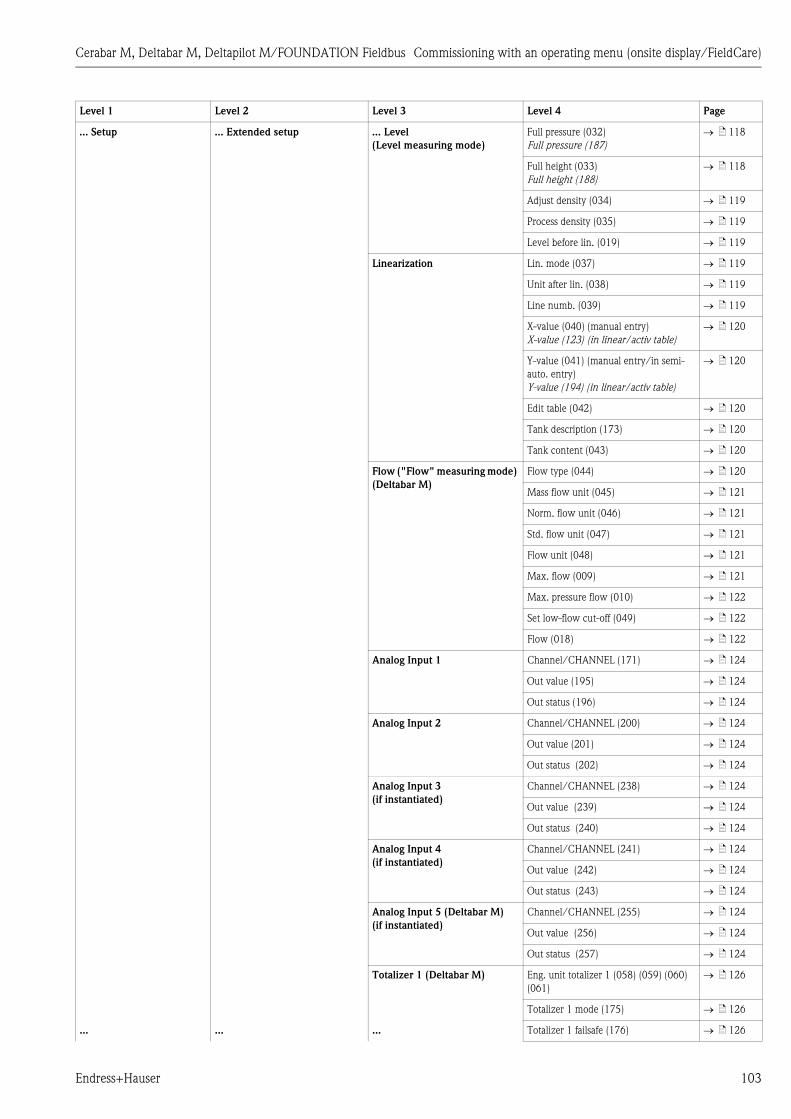
Cerabar M, Deltabar M, Deltapilot M/FOUNDATION Fieldbus Commissioning with an operating menu (onsite display/FieldCare)
Endress+Hauser 103
... Setup ... Extended setup ... Level
(Level measuring mode)
Full pressure (032)
Full pressure (187)
ä 118
Full height (033)
Full height (188)
ä 118
Adjust density (034) ä 119
Process density (035) ä 119
Level before lin. (019) ä 119
Linearization Lin. mode (037) ä 119
Unit after lin. (038) ä 119
Line numb. (039) ä 119
X-value (040) (manual entry)
X-value (123) (in linear/activ table)
ä 120
Y-value (041) (manual entry/in semi-
auto. entry)
Y-value (194) (in linear/activ table)
ä 120
Edit table (042) ä 120
Tank description (173) ä 120
Tank content (043) ä 120
Flow ("Flow" measuring mode)
(Deltabar M)
Flow type (044) ä 120
Mass flow unit (045) ä 121
Norm. flow unit (046) ä 121
Std. flow unit (047) ä 121
Flow unit (048) ä 121
Max. flow (009) ä 121
Max. pressure flow (010) ä 122
Set low-flow cut-off (049) ä 122
Flow (018) ä 122
Analog Input 1 Channel/CHANNEL (171) ä 124
Out value (195) ä 124
Out status (196) ä 124
Analog Input 2 Channel/CHANNEL (200) ä 124
Out value (201) ä 124
Out status (202) ä 124
Analog Input 3
(if instantiated)
Channel/CHANNEL (238) ä 124
Out value (239) ä 124
Out status (240) ä 124
Analog Input 4
(if instantiated)
Channel/CHANNEL (241) ä 124
Out value (242) ä 124
Out status (243) ä 124
Analog Input 5 (Deltabar M)
(if instantiated)
Channel/CHANNEL (255) ä 124
Out value (256) ä 124
Out status (257) ä 124
Totalizer 1 (Deltabar M) Eng. unit totalizer 1 (058) (059) (060)
(061)
ä 126
Totalizer 1 mode (175) ä 126
... ... ... Totalizer 1 failsafe (176) ä 126
Level 1 Level 2 Level 3 Level 4 Page

Commissioning with an operating menu (onsite display/FieldCare) Cerabar M, Deltabar M, Deltapilot M/FOUNDATION Fieldbus
104 Endress+Hauser
... Setup ... Extended setup ... Totalizer 1 (Deltabar M) Reset Totalizer 1 (062) ä 126
Totalizer 1 (063) ä 126
Totalizer 1 overflow (064) ä 126
Totalizer 2 (Deltabar M) Eng. unit totalizer 2 (065) (066) (067)
(068)
ä 127
Totalizer 2 mode (177) ä 127
Totalizer 2 failsafe (178) ä 127
Totalizer 2 (069) ä 127
Totalizer 2 overflow (070) ä 127
Diagnosis Diagnostic code (071) ä 127
Last diag. code (072) ä 127
Min. meas. press. (073) ä 127
Max. meas. press. (074) ä 128
Diagnostic list Diagnostic 1 (075) ä 128
Diagnostic 2 (076) ä 128
Diagnostic 3 (077) ä 128
Diagnostic 4 (078) ä 128
Diagnostic 5 (079) ä 128
Diagnostic 6 (080) ä 128
Diagnostic 7 (081) ä 128
Diagnostic 8 (082) ä 128
Diagnostic 9 (083) ä 128
Diagnostic 10 (084) ä 128
Event logbook Last diag. 1 (085) ä 128
Last diag. 2 (086) ä 128
Last diag. 3 (087) ä 128
Last diag. 4 (088) ä 128
Last diag. 5 (089) ä 128
Last diag. 6 (090) ä 128
Last diag. 7 (091) ä 128
Last diag. 8 (092) ä 128
Last diag. 9 (093) ä 128
Last diag. 10 (094) ä 128
Instrument info Firmware version (095) ä 111
Serial number (096) ä 111
Ext. order code (097) ä 111
Order code (098) ä 111
Pd-tag. (022) ä 111
ENP version (099) ä 111
Config. counter (100) ä 128
LRL sensor (101) ä 122
URL sensor (102) ä 122
Device type code (236) ä 123
... ... Device revision (237) ä 123
Level 1 Level 2 Level 3 Level 4 Page
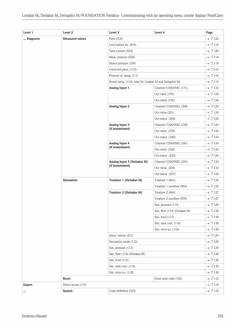
Cerabar M, Deltabar M, Deltapilot M/FOUNDATION Fieldbus Commissioning with an operating menu (onsite display/FieldCare)
Endress+Hauser 105
... Diagnosis Measured values Flow (018) ä 122
Level before lin. (019) ä 119
Tank content (043) ä 120
Meas. pressure (020) ä 116
Sensor pressure (109) ä 116
Corrected press. (172) ä 116
Pressure af. damp (111) ä 116
Sensor temp. (110) (only for Cerabar M and Deltapilot M) ä 115
Analog Input 1 Channel/CHANNEL (171) ä 124
Out value (195) ä 124
Out status (196) ä 124
Analog Input 2 Channel/CHANNEL (200) ä 124
Out value (201) ä 124
Out status (202) ä 124
Analog Input 3
(if instantiated)
Channel/CHANNEL (238) ä 124
Out value (239) ä 124
Out status (240) ä 124
Analog Input 4
(if instantiated)
Channel/CHANNEL (241) ä 124
Out value (242) ä 124
Out status (243) ä 124
Analog Input 5 (Deltabar M)
(if instantiated)
Channel/CHANNEL (255) ä 124
Out value (256) ä 124
Out status (257) ä 124
Simulation Totalizer 1 (Deltabar M) Totalizer 1 (063) ä 126
Totalizer 1 overflow (064) ä 126
Totalizer 2 (Deltabar M) Totalizer 2 (069) ä 127
Totalizer 2 overflow (070) ä 127
Sim. pressure (113) ä 129
Sim. flow (114) (Deltabar M) ä 130
Sim. level (115) ä 130
Sim. tank cont. (116) ä 130
Sim. error no. (118) ä 130
Simul. switch (251) ä 129
Simulation mode (112) ä 129
Sim. pressure (113) ä 129
Sim. flow (114) (Deltabar M) ä 130
Sim. level (115) ä 130
Sim. tank cont. (116) ä 130
Sim. error no. (118) ä 130
Reset Enter reset code (124) ä 112
Expert Direct access (119) ä 110
... System Code definition (023) ä 110
Level 1 Level 2 Level 3 Level 4 Page

Commissioning with an operating menu (onsite display/FieldCare) Cerabar M, Deltabar M, Deltapilot M/FOUNDATION Fieldbus
106 Endress+Hauser
... Expert ... System Lock switch (120) ä 110
Operator code (021) ä 110
Instrument info Pd-tag. (022) Pd-tag. (022) ä 111
... Instrument info Serial number (096) ä 111
Firmware version (095) ä 111
Ext. order code (097) ä 111
Order code (098) ä 111
ENP version (099) ä 111
Electr. serial no. (121) ä 111
Sensor serial no. (122) ä 111
Display Language (000) ä 111
Display mode (001) ä 111
Add. disp. value (002) ä 111
Format 1st value (004) ä 112
FF input source (233) ä 112
FF input unit (234) ä 112
FF input form (235) ä 112
Management Enter reset code (124) ä 112
Download select ä 113
Measurement Lin./SQRT switch (133) (Deltabar) ä 113
Measuring mode (005)
Measuring mode (182)
ä 113
Basic setup Pos. zero adjust (007) (Deltabar M and
gauge pressure sensor)
ä 114
Calib. offset (192) / (008) (absolute
pressure sensor)
ä 114
Damping switch (164) ä 114
Damping value (017)
Damping value (184)
ä 114
Press. eng. unit (125) ä 114
Temp. eng. unit (126) (only for
Cerabar M and Deltapilot M)
ä 115
Sensor temp. (110) ä 115
Pressure Switch P1/P2 (163) ä 115
High-pressure side (006) (Deltabar)
High-pressure side (183) (Deltabar)
ä 115
Meas. pressure (020) ä 116
Sensor pressure (109) ä 116
Corrected press. (172) ä 116
Pressure af. damp (111) ä 116
Level Level selection (024) ä 117
Unit before lin. (025) ä 117
Height unit (026) ä 117
Calibration mode (027) ä 117
... ... ... Empty calib. (028) ä 118
Level 1 Level 2 Level 3 Level 4 Page
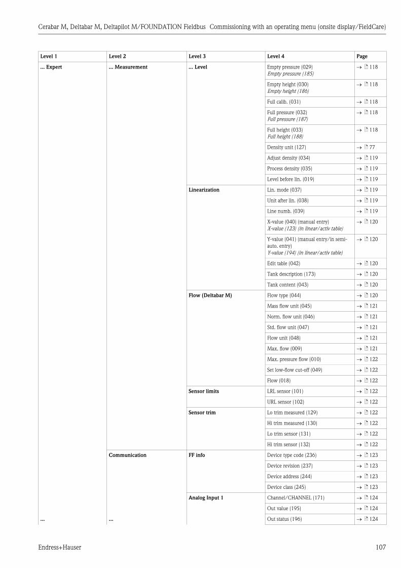
Cerabar M, Deltabar M, Deltapilot M/FOUNDATION Fieldbus Commissioning with an operating menu (onsite display/FieldCare)
Endress+Hauser 107
... Expert ... Measurement ... Level Empty pressure (029)
Empty pressure (185)
ä 118
Empty height (030)
Empty height (186)
ä 118
Full calib. (031) ä 118
Full pressure (032)
Full pressure (187)
ä 118
Full height (033)
Full height (188)
ä 118
Density unit (127) ä 77
Adjust density (034) ä 119
Process density (035) ä 119
Level before lin. (019) ä 119
Linearization Lin. mode (037) ä 119
Unit after lin. (038) ä 119
Line numb. (039) ä 119
X-value (040) (manual entry)
X-value (123) (in linear/activ table)
ä 120
Y-value (041) (manual entry/in semi-
auto. entry)
Y-value (194) (in linear/activ table)
ä 120
Edit table (042) ä 120
Tank description (173) ä 120
Tank content (043) ä 120
Flow (Deltabar M) Flow type (044) ä 120
Mass flow unit (045) ä 121
Norm. flow unit (046) ä 121
Std. flow unit (047) ä 121
Flow unit (048) ä 121
Max. flow (009) ä 121
Max. pressure flow (010) ä 122
Set low-flow cut-off (049) ä 122
Flow (018) ä 122
Sensor limits LRL sensor (101) ä 122
URL sensor (102) ä 122
Sensor trim Lo trim measured (129) ä 122
Hi trim measured (130) ä 122
Lo trim sensor (131) ä 122
Hi trim sensor (132) ä 122
Communication FF info Device type code (236) ä 123
Device revision (237) ä 123
Device address (244) ä 123
Device class (245) ä 123
Analog Input 1 Channel/CHANNEL (171) ä 124
Out value (195) ä 124
... ... Out status (196) ä 124
Level 1 Level 2 Level 3 Level 4 Page

Commissioning with an operating menu (onsite display/FieldCare) Cerabar M, Deltabar M, Deltapilot M/FOUNDATION Fieldbus
108 Endress+Hauser
... Expert ... Communication Analog Input 2 Channel/CHANNEL (200) ä 124
Out value (201) ä 124
Out status (202) ä 124
Analog Input 3
(if instantiated)
Channel/CHANNEL (238) ä 124
Out value (239) ä 124
Out status (240) ä 124
Analog Input 4
(if instantiated)
Channel/CHANNEL (241) ä 124
Out value (242) ä 124
Out status (243) ä 124
Analog Input 5 (Deltabar M)
(if instantiated)
Channel/CHANNEL (255) ä 124
Out value (256) ä 124
Out status (257) ä 124
Application Electr. delta P (158) ä 125
Fixed ext. value (174) ä 125
E.Delta p selec. (246) ä 125
E.Delta p value (247) ä 125
E.Delta p status (248) ä 125
E.Delta p unit (249) ä 125
Totalizer 1 (Deltabar M) Eng. unit totalizer 1 (058) (059) (060)
(061)
ä 126
Totalizer 1 mode (175) ä 126
Totalizer 1 failsafe (176) ä 126
Reset Totalizer 1 (062) ä 126
Totalizer 1 (063) ä 126
Totalizer 1 overflow (064) ä 126
Totalizer 2 (Deltabar M) Eng. unit totalizer 2 (065) (066) (067)
(068)
ä 127
Totalizer 2 mode (177) ä 127
Totalizer 2 failsafe (178) ä 127
Totalizer 2 (069) ä 127
Totalizer 2 overflow (070) ä 127
Diagnosis Diagnostic code ä 127
Last diag. code (072) ä 127
Reset logbook (159) ä 127
Min. meas. press. (073) ä 127
Max. meas. press. (074) ä 128
Reset peakhold (161) ä 128
Alarm behav. P (050) ä 128
Operating hours (162) ä 128
Config. counter (100) ä 128
Diagnostic list Diagnostic 1 (075) ä 128
Diagnostic 2 (076) ä 128
Diagnostic 3 (077) ä 128
Diagnostic 4 (078) ä 128
... ... ... Diagnostic 5 (079) ä 128
Level 1 Level 2 Level 3 Level 4 Page

Cerabar M, Deltabar M, Deltapilot M/FOUNDATION Fieldbus Commissioning with an operating menu (onsite display/FieldCare)
Endress+Hauser 109
... Expert ... Diagnosis ... Diagnostic list Diagnostic 6 (080) ä 128
Diagnostic 7 (081) ä 128
Diagnostic 8 (082) ä 128
Diagnostic 9 (083) ä 128
Diagnostic 10 (084) ä 128
Event logbook Last diag. 1 (085) ä 128
Last diag. 2 (086) ä 128
Last diag. 3 (087) ä 128
Last diag. 4 (088) ä 128
Last diag. 5 (089) ä 128
Last diag. 6 (090) ä 128
Last diag. 7 (091) ä 128
Last diag. 8 (092) ä 128
Last diag. 9 (093) ä 128
Last diag. 10 (094) ä 128
Simulation Simul. switch ä 129
Simulation mode ä 129
Sim. pressure ä 129
Sim. flow (Deltabar M) ä 130
Sim. level ä 130
Sim. tank cont. ä 130
Sim. error no. ä 130
Level 1 Level 2 Level 3 Level 4 Page
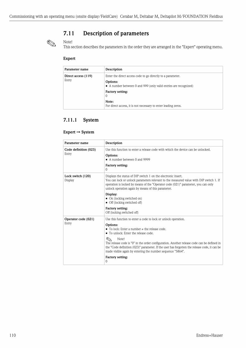
Commissioning with an operating menu (onsite display/FieldCare) Cerabar M, Deltabar M, Deltapilot M/FOUNDATION Fieldbus
110 Endress+Hauser
7.11 Description of parameters
! Note!
This section describes the parameters in the order they are arranged in the "Expert" operating menu.
Expert
7.11.1 System
Expert ➞ System
Parameter name Description
Direct access (119)
Entry
Enter the direct access code to go directly to a parameter.
Options:
• A number between 0 and 999 (only valid entries are recognized)
Factory setting:
0
Note:
For direct access, it is not necessary to enter leading zeros.
Parameter name Description
Code definition (023)
Entry
Use this function to enter a release code with which the device can be unlocked.
Options:
• A number between 0 and 9999
Factory setting:
0
Lock switch (120)
Display
Displays the status of DIP switch 1 on the electronic insert.
You can lock or unlock parameters relevant to the measured value with DIP switch 1. If
operation is locked by means of the "Operator code (021)" parameter, you can only
unlock operation again by means of this parameter.
Display:
• On (locking switched on)
• Off (locking switched off)
Factory setting:
Off (locking switched off)
Operator code (021)
Entry
Use this function to enter a code to lock or unlock operation.
Options:
• To lock: Enter a number the release code.
• To unlock: Enter the release code.
! Note!
The release code is "0" in the order configuration. Another release code can be defined in
the "Code definition (023)" parameter. If the user has forgotten the release code, it can be
made visible again by entering the number sequence "5864".
Factory setting:
0

Cerabar M, Deltabar M, Deltapilot M/FOUNDATION Fieldbus Commissioning with an operating menu (onsite display/FieldCare)
Endress+Hauser 111
Expert ➞ System ➞ Instrument info
Expert ➞ System ➞ Display
Parameter name Description
Pd-tag. (022)
Display
Physical device tag
Example:
Deltabar M: EH_Deltabar_M_5x_6B032A0109D
Serial number (096)
Display
Displays the serial number of the device (11 alphanumeric characters).
Firmware version (095)
Display
Displays the firmware version.
Ext. order code (097)
Display
Displays the extended order code (max. 60 alphanumeric characters).
Factory setting
As per order specifications
Order code (098)
Display
Displays the order code (max. 20 alphanumeric characters).
Factory setting
As per order specifications
ENP version (099)
Display
Displays the ENP version
(ENP = electronic nameplate)
Electr. serial no. (121)
Display
Displays the serial number of the main electronics (11 alphanumeric characters).
Sensor serial no. (122)
Display
Displays the serial number of the sensor (11 alphanumeric characters).
Parameter name Description
Language (000)
Options
Select the menu language for the onsite display.
Options:
• English
• Possibly another language (as selected when ordering the device)
• One further language (language of the manufacturing plant)
Factory setting:
English
Display mode (001)
Options
Specify the contents for the first line of the onsite display in the measuring mode.
Options:
• Only primary value (value+bar graph)
• External value only (value+status)
• All alternating (primary value+secondary value+ext.value)
Factory setting:
Primary value (PV)
Add. disp. value (002)
Options
Specify the contents for the second line of the onsite display in the measuring mode.
Options:
• No value
• Pressure
• Main value (%)
• Totalizer 1 (Deltabar M)
• Totalizer 2 (Deltabar M)
The options depend on the measuring mode chosen.
Factory setting:
No value
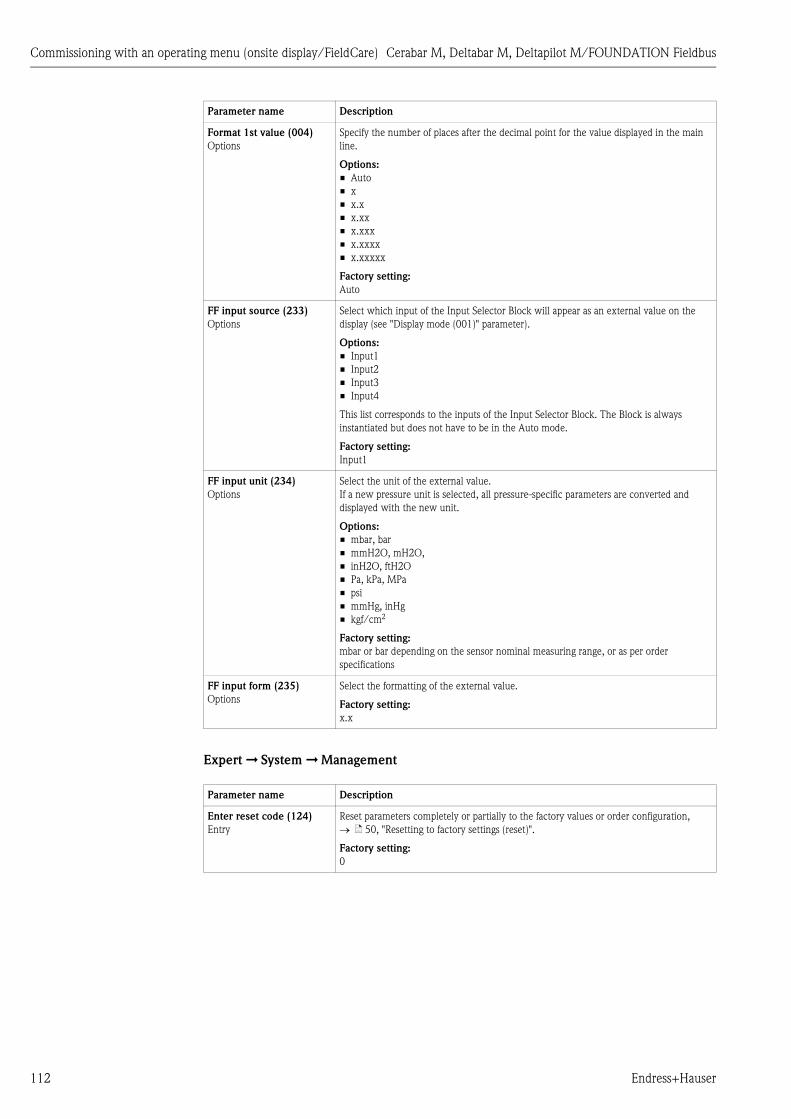
Commissioning with an operating menu (onsite display/FieldCare) Cerabar M, Deltabar M, Deltapilot M/FOUNDATION Fieldbus
112 Endress+Hauser
Expert ➞ System ➞ Management
Format 1st value (004)
Options
Specify the number of places after the decimal point for the value displayed in the main
line.
Options:
• Auto
• x
• x.x
• x.xx
• x.xxx
• x.xxxx
• x.xxxxx
Factory setting:
Auto
FF input source (233)
Options
Select which input of the Input Selector Block will appear as an external value on the
display (see "Display mode (001)" parameter).
Options:
• Input1
• Input2
• Input3
• Input4
This list corresponds to the inputs of the Input Selector Block. The Block is always
instantiated but does not have to be in the Auto mode.
Factory setting:
Input1
FF input unit (234)
Options
Select the unit of the external value.
If a new pressure unit is selected, all pressure-specific parameters are converted and
displayed with the new unit.
Options:
• mbar, bar
• mmH2O, mH2O,
• inH2O, ftH2O
• Pa, kPa, MPa
• psi
• mmHg, inHg
• kgf/cm2
Factory setting:
mbar or bar depending on the sensor nominal measuring range, or as per order
specifications
FF input form (235)
Options
Select the formatting of the external value.
Factory setting:
x.x
Parameter name Description
Enter reset code (124)
Entry
Reset parameters completely or partially to the factory values or order configuration,
ä 50, "Resetting to factory settings (reset)".
Factory setting:
0
Parameter name Description

Cerabar M, Deltabar M, Deltapilot M/FOUNDATION Fieldbus Commissioning with an operating menu (onsite display/FieldCare)
Endress+Hauser 113
7.11.2 Measurement
Expert ➞ Measurement
Download select
Display
Selection of data records for the Upload/Download function in Fieldcare.
Prerequisite:
DIP switch 1, 3, 4 and 5 set to "OFF", DIP switch 2 set to "ON" (see picture in
Chap. 5.2.1)).
A download with the factory setting "Copy configuration" causes all parameters needed
for a measurement to be downloaded. If the "Copy configuration" setting is changed, it
takes effect only when a corresponding release code is entered into the parameter
"Operator code/S_W_LOCK".
Options:
• Copy configuration: With this option, general configuration parameters are overwritten
except for serial number, order number, calibration, position adjustment, application,
and tag information.
• Device replacement: With this option, general configuration parameters are
overwritten except for serial number, order number, calibration and position
adjustment.
• Electronics replacement: This option contains all parameters from "Configuration copy"
and "Device replacement" and: "position adjustment", "sensor trimm", "serial number",
"order number".
! Note!
The control strategy is not affected by a download.
Selection of device replacement or electronics replacement takes effect only if a
corresponding release code has been entered beforehand.
Factory setting:
Copy configuration
Parameter name Description
Lin./SQRT switch (133)
(Deltabar)
Display
Displays the status of DIP switch 4 on the electronic insert, which is used to define the
output characteristics of the device.
Display:
• SW setting
• Square root
The square root signal is used.
Factory setting
SW setting
Measuring mode (005)
Measuring mode (182)
Options
Select the measuring mode.
The operating menu is structured differently depending on the measuring mode selected.
! Note!
If the measuring mode is changed, no conversion takes place. If necessary, the device has
to be recalibrated after the measuring mode has been changed.
Options:
• Pressure
• Level
• Flow (Deltabar M only)
Factory setting
Pressure or as per order specifications
Parameter name Description
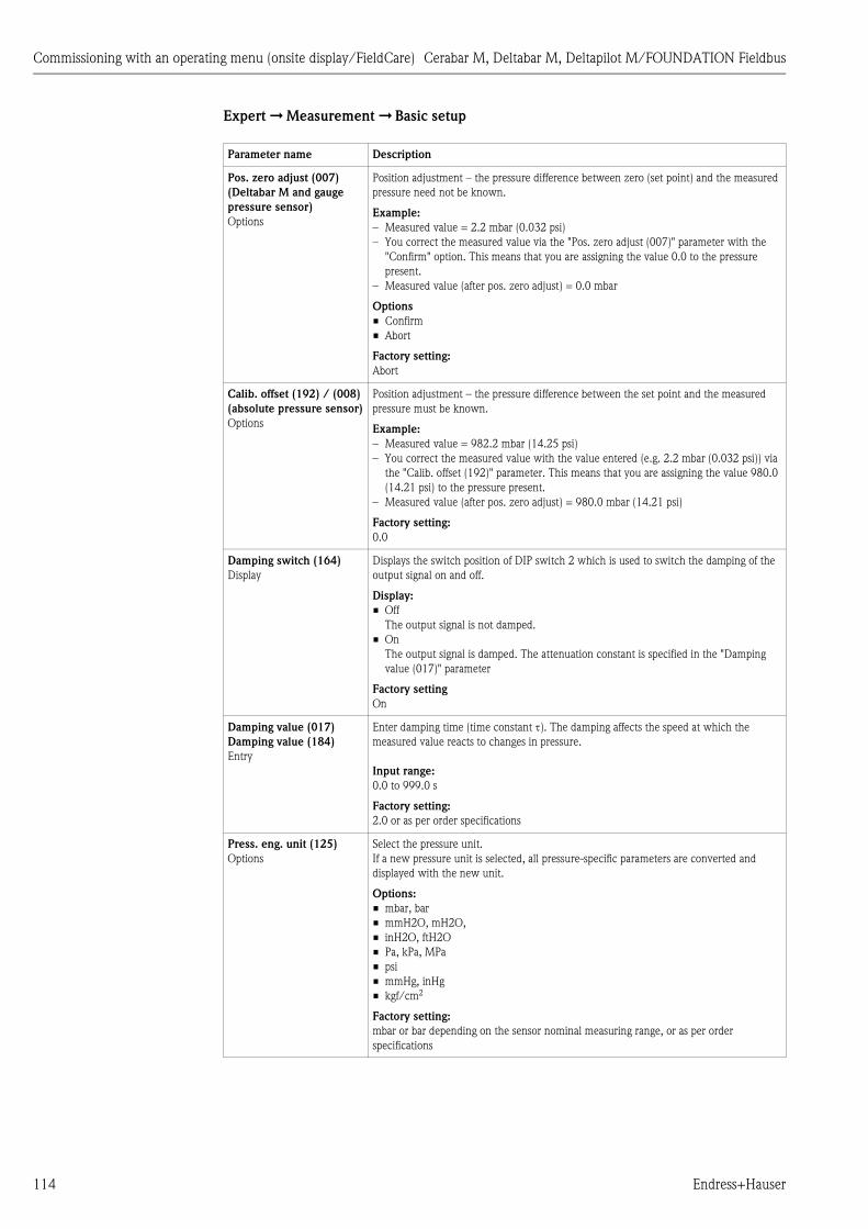
Commissioning with an operating menu (onsite display/FieldCare) Cerabar M, Deltabar M, Deltapilot M/FOUNDATION Fieldbus
114 Endress+Hauser
Expert ➞ Measurement ➞ Basic setup
Parameter name Description
Pos. zero adjust (007)
(Deltabar M and gauge
pressure sensor)
Options
Position adjustment – the pressure difference between zero (set point) and the measured
pressure need not be known.
Example:
– Measured value = 2.2 mbar (0.032 psi)
– You correct the measured value via the "Pos. zero adjust (007)" parameter with the
"Confirm" option. This means that you are assigning the value 0.0 to the pressure
present.
– Measured value (after pos. zero adjust) = 0.0 mbar
Options
• Confirm
• Abort
Factory setting:
Abort
Calib. offset (192) / (008)
(absolute pressure sensor)
Options
Position adjustment – the pressure difference between the set point and the measured
pressure must be known.
Example:
– Measured value = 982.2 mbar (14.25 psi)
– You correct the measured value with the value entered (e.g. 2.2 mbar (0.032 psi)) via
the "Calib. offset (192)" parameter. This means that you are assigning the value 980.0
(14.21 psi) to the pressure present.
– Measured value (after pos. zero adjust) = 980.0 mbar (14.21 psi)
Factory setting:
0.0
Damping switch (164)
Display
Displays the switch position of DIP switch 2 which is used to switch the damping of the
output signal on and off.
Display:
• Off
The output signal is not damped.
• On
The output signal is damped. The attenuation constant is specified in the "Damping
value (017)" parameter
Factory setting
On
Damping value (017)
Damping value (184)
Entry
Enter damping time (time constant ). The damping affects the speed at which the
measured value reacts to changes in pressure.
Input range:
0.0 to 999.0 s
Factory setting:
2.0 or as per order specifications
Press. eng. unit (125)
Options
Select the pressure unit.
If a new pressure unit is selected, all pressure-specific parameters are converted and
displayed with the new unit.
Options:
• mbar, bar
• mmH2O, mH2O,
• inH2O, ftH2O
• Pa, kPa, MPa
• psi
• mmHg, inHg
• kgf/cm2
Factory setting:
mbar or bar depending on the sensor nominal measuring range, or as per order
specifications

Cerabar M, Deltabar M, Deltapilot M/FOUNDATION Fieldbus Commissioning with an operating menu (onsite display/FieldCare)
Endress+Hauser 115
Expert ➞ Measurement ➞ Pressure
Temp. eng. unit (126)
(only for Cerabar M and
Deltapilot M)
Options
Select the unit for the temperature measured values.
! Note!
The setting affects the unit for the "Sensor temp. (110)" parameter.
Options:
• °C
• °F
• K
Factory setting:
°C
Sensor temp. (110)
(only for Cerabar M and
Deltapilot M)
Display
Displays the temperature currently measured in the sensor. This can deviate from the
process temperature.
Parameter name Description
Switch P1/P2 (163)
Display
Indicates whether the "SW/P2 High" DIP switch (DIP switch 5) is switched on.
! Note!
The "SW/P2 High" DIP switch determines which pressure input corresponds to the high-
pressure side.
Display:
• SW setting
"SW/P2 High" is switched off: The "High-pressure side (006) (Deltabar)" parameter
determines which pressure input corresponds to the high-pressure side.
• P2 High
"SW/P2 High" is switched on: Pressure input P2 corresponds to the high-pressure side,
independent of the setting in the "High-pressure side (006) (Deltabar)" parameter.
Factory setting:
SW setting
High-pressure side (006)
(Deltabar)
High-pressure side (183)
(Deltabar)
Options
Determines, which pressure input corresponds to the high-pressure side.
! Note!
This setting is only valid if the "SW/P2 High" DIP switch is in the OFF position (see
"Switch P1/P2 (163)" parameter). Otherwise P2 corresponds to the high-pressure side in
any case.
Options:
• P1 High
Pressure input P1 is the high-pressure side.
• P2 High
Pressure input P2 is the high-pressure side.
Factory setting
P1 High
Parameter name Description
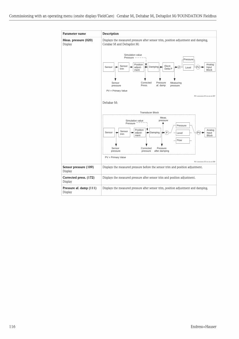
Commissioning with an operating menu (onsite display/FieldCare) Cerabar M, Deltabar M, Deltapilot M/FOUNDATION Fieldbus
116 Endress+Hauser
Meas. pressure (020)
Display
Displays the measured pressure after sensor trim, position adjustment and damping.
Cerabar M and Deltapilot M:
P01-xxxxxxxx-05-xx-xx-en-007
Deltabar M:
P01-xxxxxxxx-05-xx-xx-en-008
Sensor pressure (109)
Display
Displays the measured pressure before the sensor trim and position adjustment.
Corrected press. (172)
Display
Displays the measured pressure after sensor trim and position adjustment.
Pressure af. damp (111)
Display
Displays the measured pressure after sensor trim, position adjustment and damping.
Parameter name Description
P PVAnalogInputBlock
Sensor
Pressure
Level
Pressureaf. damp
Damping
CorrectedPress.
Positionadjust-ment
Sensortrim
Sensorpressure
Simulation valuePressure
Measuringpressure
Electr.Delta P
PV = Primary Value
P PVAnalogInputBlock
Sensorpressure
Transducer Block
Sensor
Pressure
LevelDampingPositionadjust-ment
Sensortrim
Flow
Correctedpressure
Pressureafter damping
Meas.pressure
PV = Primary Value
Simulation valuePressure

Cerabar M, Deltabar M, Deltapilot M/FOUNDATION Fieldbus Commissioning with an operating menu (onsite display/FieldCare)
Endress+Hauser 117
Expert ➞ Measurement ➞ Level
Parameter name Description
Level selection (024)
Options
Select the method for calculating the level
Options:
• In pressure
If this option is selected, specify two pressure/level value pairs. The level value is
displayed directly in the unit that you select via the "Unit before lin. (025)" parameter.
• In height
If this option is selected, specify two height/level value pairs. From the measured
pressure, the device first calculates the height using the density. This information is
then used to calculate the level in the "Unit before lin. (025)" selected using the two
value pairs specified.
Factory setting:
In pressure
Unit before lin. (025)
Options
Select the unit for the measured value display for the level before linearization.
! Note!
The unit selected is only used to describe the measured value. This means that the
measured value is not converted when a new output unit is selected.
Example:
• Current measured value: 0.3 ft
• New output unit: m
• New measured value: 0.3 m
Options
• %
• mm, cm, dm, m
• ft, in
• m3, in3
• l, hl
• ft3
• gal, Igal
• kg, t
• lb
Factory setting:
%
Height unit (026)
Options
Select the height unit. The measured pressure is converted to the selected height unit
using the "Adjust density (034)" parameter.
Prerequisite
"Level selection" = "In height"
Options
• mm
• m
• in
• ft
Factory setting:
m
Calibration mode (027)
Options
Select the calibration mode.
Options:
• Wet
Wet calibration takes place by filling and emptying the container. In the case of two
different levels, the level, volume, mass or percentage value entered is assigned to the
pressure measured at this point in time ("Empty calib. (028)" and "Full calib. (031)"
parameters).
• Dry
Dry calibration is a theoretical calibration. For this calibration, you specify two
pressure/level value pairs or height/level value pairs via the following parameters:
"Empty calib. (028)", "Empty pressure (029)", "Full calib. (031)", "Full pressure (032)" ,
"Empty height (030)", "Full height (033)".
Factory setting:
Wet

Commissioning with an operating menu (onsite display/FieldCare) Cerabar M, Deltabar M, Deltapilot M/FOUNDATION Fieldbus
118 Endress+Hauser
Empty calib. (028)
Empty calib. (011)
Entry
Enter the output value for the lower calibration point (container empty).
The unit defined in "Unit before lin. (025)" must be used.
! Note!
• In the case of wet calibration, the level (container empty) must actually be available.
The associated pressure is then automatically recorded by the device.
• In the case of dry calibration, the level (container empty) does not have to be available.
The associated pressure has to be entered in the "Empty pressure (029)" parameter for
the "In pressure" level selection. The associated height has to be entered in the "Empty
height (030)" parameter for the "In height" level selection.
Factory setting:
0.0
Empty pressure (029)
Empty pressure (185)
Entry/Display
Enter the pressure value for the lower calibration point (container empty).
See also "Empty calib. (028)".
Prerequisite
• "Level selection" = In pressure
• "Calibration mode" = Dry -> entry
• "Calibration mode" = Wet -> display
Factory setting:
0.0
Empty height (030)
Empty height (186)
Entry/Display
Enter the height value for the lower calibration point (container empty). Select the unit
via the "Height unit (026)" parameter.
Prerequisite:
• "Level selection" = "In height"
• "Calibration mode" = Dry -> entry
• "Calibration mode" = Wet -> display
Factory setting:
0.0
Full calib. (031)
Full calib. (012)
Entry
Enter the output value for the upper calibration point (container full).
The unit defined in "Unit before lin. (025)" must be used.
! Note!
• In the case of wet calibration, the level (container full) must actually be available. The
associated pressure is then automatically recorded by the device.
• In the case of dry calibration, the level (container full) does not have to be available.
The associated pressure has to be entered in the "Full pressure (032)" parameter for the
"In pressure" level selection. The associated height has to be entered in the "Full height
(033)" parameter for the "In height" level selection.
Factory setting:
100.0
Full pressure (032)
Full pressure (187)
Entry/Display
Enter the pressure value for the upper calibration point (container full).
See also "Full calib. (031)".
Prerequisite
• "Level selection" = In pressure
• "Calibration mode" = Dry -> entry
• "Calibration mode" = Wet -> display
Factory setting:
Upper-range limit (URL) of the sensor
Full height (033)
Full height (188)
Entry/Display
Enter the height value for the upper calibration point (container full). Select the unit via
the "Height unit (026)" parameter.
Prerequisite:
• "Level selection" = "In height"
• "Calibration mode" = Dry -> entry
• "Calibration mode" = Wet -> display
Factory setting:
Upper-range limit (URL) is converted to a height unit
Density unit (127)
Display
Displays the density unit. The measured pressure is converted to a height using the
"Height unit (026)" and "Adjust density (034)" parameters.
Factory setting:
• g/cm3
Parameter name Description

Cerabar M, Deltabar M, Deltapilot M/FOUNDATION Fieldbus Commissioning with an operating menu (onsite display/FieldCare)
Endress+Hauser 119
Expert ➞ Measurement ➞ Linearization
Adjust density (034)
Entry
Enter the density of the medium. The measured pressure is converted to a height using
the "Height unit (026)" and "Adjust density (034)" parameters.
Factory setting:
1.0
Process density (035)
Entry
Enter a new density value for density correction.
The calibration was carried out with water as the medium, for example. Now the
container is to be used for another medium with another density. The calibration is
corrected appropriately by entering the new density value in the "Process density (035)"
parameter.
! Note!
If you change to dry calibration after completing a wet calibration using the "Calibration
mode (027)" parameter, the density for the "Adjust density (034)" and "Process density
(035)" parameters must be entered correctly before changing the calibration mode.
Factory setting:
1.0
Level before lin. (019)
Display
Displays the level value prior to linearization.
Parameter name Description
Lin. mode (037)
Options
Select the linearization mode.
Options:
• Linear
The level is output without being converted beforehand. "Level before lin. (019)" is
output.
• Erase table
The existing linearization table is deleted.
• Manual entry (sets the table to the edit mode, an alarm is output):
The value pairs of the table ("X-value (040) (manual entry)" and "Y-value (041)
(manual entry/in semi-auto. entry)") are entered manually.
• Semiautomatic entry (sets the table to the edit mode, an alarm is output):
The container is emptied or filled in stages in this entry mode. The device records the
level value automatically ("X-value (040) (manual entry)"). The associated volume,
mass or %-value is entered manually ("Y-value (041) (manual entry/in semi-auto.
entry)").
• Activate table
The table entered is activated and checked with this option. The device shows the
level after linearization.
Factory setting:
Linear
Unit after lin. (038)
Options
Select the unit (unit of the Y-value).
Options:
• %
• cm, dm, m, mm
• hl
• in3, ft3, m3
• l
• in, ft
• kg, t
• lb
• gal
• Igal
Factory setting:
%
Line numb. (039)
Entry
Enter the number of the current point in the table.
The subsequent entries in "X-value (040) (manual entry)" and "Y-value (041) (manual
entry/in semi-auto. entry)" refer to this point.
Input range:
• 1 ... 32
Parameter name Description

Commissioning with an operating menu (onsite display/FieldCare) Cerabar M, Deltabar M, Deltapilot M/FOUNDATION Fieldbus
120 Endress+Hauser
Expert ➞ Measurement ➞ Flow (Deltabar M)
X-value (040) (manual
entry)
X-value (123) (in linear/
activ table)
X-value (193) (in semi-
auto. entry)
Entry/Display
Enter the X-value (value before linearization) for the specific point in the table and
confirm.
! Note!
• If "Lin. mode (037)" = "Manual", the level value must be entered.
• If "Lin. mode (037)" = "Semiautomatic", the level value is displayed and must be
confirmed by entering the associated Y-value.
Y-value (041) (manual
entry/in semi-auto. entry)
Y-value (194) (in linear/
activ table)
Entry/Display
Enter the Y-value (value after linearization) for the specific point in the table.
The unit is determined by "Unit after lin. (038)".
! Note!
The linearization table must be monotonic (increasing or decreasing).
Edit table (042)
Options
Select the function for entering the table.
Options:
• Next point: The "Line numb." parameter is increased by 1. The next point can be
entered.
• Current point: stay on the current point to correct a mistake for example.
• Previous point: The "Line numb." parameter is decreased by 1. The previous point can
be corrected/entered again.
• Insert point: insert an additional point (see example below).
• Delete point: delete the current point (see example below).
Example: Add a point - in this case between the 4th and 5th point for example
– Select point 5 via the "Line numb. (039)" parameter.
– Select the "Insert point" option via the "Edit table (042)" parameter.
– Point 5 is displayed for the "Line numb. (039)" parameter. Enter new values for the
"X-value (040) (manual entry)" and "Y-value (041) (manual entry/in semi-auto. entry)"
parameters.
Example: Delete a point - in this case the 5th point for example
– Select point 5 via the "Line numb. (039)" parameter.
– Select the "Delete point" option via the "Edit table (042)" parameter.
– The 5th point is deleted. All of the subsequent points are moved up one number
i.e. following deletion, the 6th point becomes Point 5.
Factory setting:
Current point
Tank description (173)
Entry
Enter the tank description (max. 32 alphanumeric characters)
Tank content (043)
Display
Displays the level value after linearization.
Parameter name Description
Flow type (044)
Options
Select the flow type.
Options:
• Volume process cond. (volume under operating conditions)
• Volume norm. cond. (norm volume under norm conditions in Europe: 1013.25 mbar
and 273.15 K (0°C))
• Volume std. cond. (standard volume under standard conditions in the USA:
1013.25 mbar (14.7 psi) and 288.15 K (15°C/59°F))
• Mass (mass under operating conditions)
• Flow in %
Factory setting:
Volume process conditions
Parameter name Description

Cerabar M, Deltabar M, Deltapilot M/FOUNDATION Fieldbus Commissioning with an operating menu (onsite display/FieldCare)
Endress+Hauser 121
Mass flow unit (045)
Options
Select mass flow unit.
When a new flow unit is selected, all flow-specific parameters are converted and
displayed with the new unit within a flow type. When the flow type is changed,
conversion is not possible.
Prerequisite:
• "Flow type (044)" = Mass
Options:
• g/s, kg/s, kg/min, kg/h
• t/s, t/min, t/h, t/d
• oz/s, oz/min
• lb/s, lb/min, lb/h
• ton/s, ton/min, ton/h, ton/day
Factory setting:
kg/s
Norm. flow unit (046)
Options
Select norm flow unit.
When a new flow unit is selected, all flow-specific parameters are converted and
displayed with the new unit within a flow type. When the flow type is changed,
conversion is not possible.
Prerequisite:
• "Flow type (044)" = Volume norm. cond.
Options:
• Nm3/s, Nm3/min, Nm3/h, Nm3/d
Factory setting:
Nm3/s
Std. flow unit (047)
Options
Select standard flow unit.
When a new flow unit is selected, all flow-specific parameters are converted and
displayed with the new unit within a flow type. When the flow type is changed,
conversion is not possible.
Prerequisite:
• "Flow type (044)" = Volume std. conditions
Options:
• Sm3/s, Sm3/min, Sm3/h, Sm3/day
• SCFS, SCFM, SCFH, SCFD
Factory setting:
Sm3/s
Flow unit (048)
Options
Select volume flow unit.
When a new flow unit is selected, all flow-specific parameters are converted and
displayed with the new unit within a flow type. When the flow type is changed,
conversion is not possible.
Prerequisite:
• "Flow type (044)" = Volume process cond.
Options:
• dm3/s, dm3/min, dm3/h
• m3/s, m3/min, m3/h, m3/d
• l/s, l/min, l/h
• hl/s, hl/min, hl/day
• ft3/s, ft3/min, ft3/h, ft3/d
• ACFS, ACFM, ACFH, ACFD
• ozf/s, ozf/min
• gal/s, gal/min, gal/h, gal/d, Mgal/d
• Igal/s, Igal/min, Igal/h
• bbl/s, bbl/min, bbl/h, bbl/d
Factory setting:
m3/s
Max. flow (009)
Entry
Enter maximum flow of primary element.
See also layout sheet of primary element. The maximum flow is assigned to the maximum
pressure which you enter via "Max. pressure flow (010)".
Factory setting:
100.0
Parameter name Description

Commissioning with an operating menu (onsite display/FieldCare) Cerabar M, Deltabar M, Deltapilot M/FOUNDATION Fieldbus
122 Endress+Hauser
Expert ➞ Measurement ➞ Sensor limits
Expert ➞ Measurement ➞ Sensor trim
Max. pressure flow (010)
Entry
Enter maximum pressure of primary element.
See layout sheet of primary element. This value is assigned to the maximum flow value
(see "Max. flow (009)").
Factory setting:
Upper-range limit (URL) of the sensor
Set low-flow cut-off (049)
Entry
Enter switch-on point of the flow-flow cut-off.
The hysteresis between the switch-on point and the switch-off point is always 1 % of the
maximum flow value.
Input range:
Switch-off point: 0 to 50% of end flow value ("Max. flow (009)").
P01-PMD7xxxx-05-xx-xx-xx-000
Factory setting:
5 % (of the maximum flow value)
Flow (018)
Display
Displays the present flow value.
Parameter name Description
LRL sensor (101)
Display
Displays the lower-range limit of the sensor.
URL sensor (102)
Display
Displays the upper-range limit of the sensor.
Parameter name Description
Lo trim measured (129)
Display
Displays the reference pressure present to be accepted for the lower calibration point.
Hi trim measured (130)
Display
Displays the reference pressure present to be accepted for the upper calibration point.
Lo trim sensor (131)
Display
Internal service parameter.
Hi trim sensor (132)
Display
Internal service parameter.
Parameter name Description
6%
5%
➀ ➁
0%0%
QQmax
QQmax
Δp Δp

Cerabar M, Deltabar M, Deltapilot M/FOUNDATION Fieldbus Commissioning with an operating menu (onsite display/FieldCare)
Endress+Hauser 123
7.11.3 Communication
Expert ➞ Communication ➞ FF Info
Expert ➞ Communication ➞ Resource Block (only with FieldCare)
See ä 159 ff.
Expert ➞ Communication ➞ Transducer Blocks (only with FieldCare)
See ä 168 ff.
Parameter name Description
Device type code (236)
Display
The "Device type code (236)" is the unique device ID in the control system or the FF bus.
It consists of the manufacturer ID (452B48), device type number and device serial
number.
Example:
Deltabar M: 452B481021-6B032A0109D
Device revision (237)
Display
Displays the revision or version of a complete device (HW+SW).
Example:
1
Device address (244)
Display
Displays the device address currently configured and valid.
Factory setting:
247
Device class (245)
Display
Displays the device class currently configured.
The device can be configured as a "Basic device" or "Link master".
Factory setting:
Basic device

Commissioning with an operating menu (onsite display/FieldCare) Cerabar M, Deltabar M, Deltapilot M/FOUNDATION Fieldbus
124 Endress+Hauser
Expert ➞ Communication ➞ Analog Input 1 to 5
* Not available for Deltabar M.
Analog Input Parameter name (Display Id) Explanation
1 Channel/CHANNEL (171)
See the following table.
Out value (195)
Out status (196)
2 Channel/CHANNEL (200)
Out value (201)
Out status (202)
3 Channel/CHANNEL (238)
Out value (239)
Out status (240)
4 Channel/CHANNEL (241)
Out value (242)
Out status (243)
5 (Deltabar M) Channel/CHANNEL (255)
Out value (256)
Out status (257)
Parameter name Description
Channel/
CHANNEL
Display
The current selected Channel/CHANNEL is displayed for instantiated analog inputs. The following
list indicates the possible channels:
Channel
/
CHANN
EL
(Set as Default for
pre-instantiated Block)
English text German Text
1
2 *
3
4
5
(AI 1)
(AI 2) Cerabar/Deltapilot
(AI 2) Deltabar
-
-
Primary value
Sensor temperature *
Pressure
Max. pressure
Level before linearization
Totalizer 1
Totalizer 2
Hauptmesswert
Sensortemperatur *
Druck gemessen
Maximaler Druck
Füllstand vor Linearisierung
Summenzähler 1
Summenzähler 2
Out value
Display
The current value is displayed for instantiated analog inputs, along with the individual units.
Out status
Display
The current status is displayed for instantiated analog inputs.
The following list indicates the status and the related text of the AI OUT value:
Status
Bad
Uncertain
Good non-cascaded
Good cascaded
=
=
=
=
Text
BAD
UNCERTAIN
GOOD
GOOD

Cerabar M, Deltabar M, Deltapilot M/FOUNDATION Fieldbus Commissioning with an operating menu (onsite display/FieldCare)
Endress+Hauser 125
7.11.4 Application
Expert ➞ Application (Cerabar M and Deltapilot M)
Parameter name Description
Electr. delta P (158)
Entry
For switching the electr. delta P application on or off with an external or constant value.
Options:
Off
External value
Constant
Factory setting:
Off
Fixed ext. value (174)
Entry
Use this function to enter the constant value.
The value refers to "Press. eng. unit (125)".
Factory setting:
0.0
E.Delta p selec. (246)
Entry
Select which input of the Input Selector Block is chosen as the input value for Electrical
Delta P. The input is selected from a picklist (Input1 - Input4). This list corresponds to the
inputs of the Input Selector Block. The Block is always instantiated and does not have to
be in the Auto mode.
Factory setting:
Input1
E.Delta p value (247)
Entry
The corresponding Electrical Delta P. value is displayed for the selected input.
E.Delta p status (248)
Entry
The corresponding Electrical Delta P. status is displayed for the selected input.
The following list indicates the status and the text associated with the status:
Status = Text
Bad = BAD
Uncertain = UNCERTAIN
Good non-cascaded = GOOD
Good cascaded = GOOD
E.Delta p unit (249)
Entry
Select which unit corresponds to the value of the selected inputs.
Factory setting:
mbar

Commissioning with an operating menu (onsite display/FieldCare) Cerabar M, Deltabar M, Deltapilot M/FOUNDATION Fieldbus
126 Endress+Hauser
Expert ➞ Application ➞ Totalizer 1 (Deltabar M)
! Note!
With the "Flow in %" flow type setting, the totalizer is not available and is not displayed at this
position.
Parameter name Description
Eng. unit totalizer 1
(058) (059) (060) (061)
Options
Select unit for totalizer 1.
Options
Depending on the setting in the "Flow type (044)" parameter, this parameter offers a list
of volume, norm volume, standard volume and mass units. When a new volume or mass
unit is selected, totalizer-specific parameters are converted and displayed with the new
unit within a unit group. When the flow mode is change, the totalizer value is not
converted.
The Direct Access Code depends on the selected "Flow type (044)":
– (058): Flow. meas. type "Mass"
– (059): Flow. meas. type "Volume norm. cond."
– (060): Flow. meas. type "Volume std. cond."
– (061): Flow. meas. type "Volume process cond."
Factory setting:
m3
Totalizer 1 mode (175)
Options
Define the behavior of the totalizer.
Options:
• Balanced: Integration of all measured flows (positive and negative)
• Pos. flow only: only positive flows are integrated.
• Neg. flow only: only negative flows are integrated.
• Hold: The totalizer is stopped and keeps its current value.
Factory setting:
Pos. flow only
Totalizer 1 failsafe (176) Define the behavior of the totalizer in the case of an error.
Options:
• Actual value (It is integrated with the current flow value on.)
• Hold: The totalizer is stopped and keeps its current value.
Factory setting:
Actual value
Reset Totalizer 1 (062)
Options
You reset totalizer 1 to zero with this parameter.
Options:
• Abort (do not reset)
• Reset
Factory setting:
Abort
Totalizer 1 (063)
Display
Displays the total value of totalizer 1. You can reset the value with the "Reset Totalizer 1
(062)" parameter. The "Totalizer 1 overflow (064)" parameter displays the overflow.
Example: The value 123456789 m3 is indicated as follows:
– Totalizer 1: 3456789 m3
– Totalizer 1 overflow: 12 E7 m3
Totalizer 1 overflow (064)
Display
Displays the overflow value of totalizer 1.
See also "Totalizer 1 (063)".

Cerabar M, Deltabar M, Deltapilot M/FOUNDATION Fieldbus Commissioning with an operating menu (onsite display/FieldCare)
Endress+Hauser 127
Expert ➞ Application ➞ Totalizer 2 (Deltabar M)
! Note!
With the "Flow in %" flow type setting, the totalizer is not available and is not displayed at this
position.
7.11.5 Diagnosis
Expert ➞ Diagnosis
Parameter name Description
Eng. unit totalizer 2
(065) (066) (067) (068)
Options
Select the unit for totalizer 2.
See also "Eng. unit totalizer 1".
The Direct Access Code depends on the selected "Flow type (044)":
– (065): Flow. meas. type "Mass"
– (066): Flow. meas. type "Gas norm. cond."
– (067): Flow. meas. type "Gas. std. cond."
– (068): Flow. meas. type "Volume process cond."
Factory setting:
m3
Totalizer 2 mode (177) Define the behavior of the totalizer.
Options:
• Balanced: Integration of all measured flows (positive and negative)
• Pos. flow only: only positive flows are integrated.
• Neg. flow only: only negative flows are integrated.
• Hold: The totalizer is stopped and keeps its current value.
Factory setting:
Pos. flow only
Totalizer 2 failsafe (178) Define the behavior of the totalizer in the case of an error.
Options:
• Actual value: It is integrated with the current flow value on.
• Hold: The totalizer is stopped and keeps its current value.
Factory setting:
Actual value
Totalizer 2 (069)
Display
Displays the totalizer value. The Totalizer 2 overflow (070) parameter displays the
overflow.
See the example for "Totalizer 1".
Totalizer 2 overflow (070)
Display
Displays the overflow value of totalizer 2.
See also "Totalizer 2 (069)" and example for totalizer 1.
Parameter name Description
Diagnostic code (071)
Display
Displays the diagnostic message with the highest priority currently present.
Last diag. code (072)
Display
Displays the last diagnostic message that occurred and was rectified.
! Note!
• Digital communication: the last message is displayed.
• The messages listed in the "Last diag. code (072)" parameter can be deleted via the
"Reset logbook (159)" parameter.
Reset logbook (159)
Options
With this parameter, you reset all the messages of the "Last diag. code (072)" parameter
and the "Last diag. 1 (085)" to "Last diag. 10 (094)" event log.
Options:
• Abort
• Confirm
Factory setting:
Abort
Min. meas. press. (073)
Display
Displays the lowest pressure value measured (peakhold indicator). You can reset this
indicator by means of the "Reset peakhold (161)" parameter.

Commissioning with an operating menu (onsite display/FieldCare) Cerabar M, Deltabar M, Deltapilot M/FOUNDATION Fieldbus
128 Endress+Hauser
Expert ➞ Diagnosis ➞ Diagnostic list
Expert ➞ Diagnosis ➞ Event logbook
Max. meas. press. (074)
Display
Displays the highest pressure value measured (peakhold indicator). You can reset this
indicator by means of the "Reset peakhold (161)" parameter.
Reset peakhold (161)
Options
You can reset the "Min. meas. press." and "Max. meas. press." indicators with this
parameter.
Options:
• Abort
• Confirm
Factory setting:
Abort
Alarm behav. P (050)
Selection
Configure the current output for when the sensor limits are undershot or overshot.
Options:
• Warning
The device continues measuring. An error message is displayed. The measuring value
status shows "UNCERTAIN".
• Alarm
The measuring value status shows "BAD". An error message is displayed
Factory setting:
Warning
Operating hours (162)
Display
Displays the hours of operation. This parameter cannot be reset.
Config. counter (100)
Display
Displays the configuration counter.
This counter is increased by one every time a parameter or group is changed. The counter
counts up to 65535 and then starts again at zero.
Parameter name Description
Diagnostic 1 (075)
Diagnostic 2 (076)
Diagnostic 3 (077)
Diagnostic 4 (078)
Diagnostic 5 (079)
Diagnostic 6 (080)
Diagnostic 7 (081)
Diagnostic 8 (082)
Diagnostic 9 (083)
Diagnostic 10 (084)
These parameters contain up to ten diagnosis messages that are currently pending,
arranged in order of priority.
Parameter name Description
Last diag. 1 (085)
Last diag. 2 (086)
Last diag. 3 (087)
Last diag. 4 (088)
Last diag. 5 (089)
Last diag. 6 (090)
Last diag. 7 (091)
Last diag. 8 (092)
Last diag. 9 (093)
Last diag. 10 (094)
These parameters contain the last 10 diagnosis messages to occur and be rectified.
They can be reset using the "Reset logbook (159)" parameter.
Errors which have occurred multiple times are displayed once only.
Parameter name Description
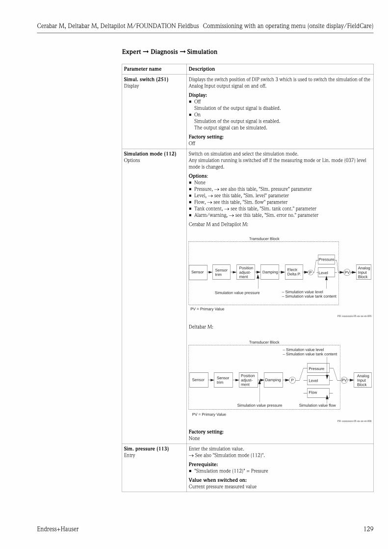
Cerabar M, Deltabar M, Deltapilot M/FOUNDATION Fieldbus Commissioning with an operating menu (onsite display/FieldCare)
Endress+Hauser 129
Expert ➞ Diagnosis ➞ Simulation
Parameter name Description
Simul. switch (251)
Display
Displays the switch position of DIP switch 3 which is used to switch the simulation of the
Analog Input output signal on and off.
Display:
• Off
Simulation of the output signal is disabled.
• On
Simulation of the output signal is enabled.
The output signal can be simulated.
Factory setting:
Off
Simulation mode (112)
Options
Switch on simulation and select the simulation mode.
Any simulation running is switched off if the measuring mode or Lin. mode (037) level
mode is changed.
Options:
• None
• Pressure, see also this table, "Sim. pressure" parameter
• Level, see this table, "Sim. level" parameter
• Flow, see this table, "Sim. flow" parameter
• Tank content, see this table, "Sim. tank cont." parameter
• Alarm/warning, see this table, "Sim. error no." parameter
Cerabar M and Deltapilot M:
P01-xxxxxxxx-05-xx-xx-en-005
Deltabar M:
P01-xxxxxxxx-05-xx-xx-en-006
Factory setting:
None
Sim. pressure (113)
Entry
Enter the simulation value.
See also "Simulation mode (112)".
Prerequisite:
• "Simulation mode (112)" = Pressure
Value when switched on:
Current pressure measured value
P PVAnalogInputBlock
Simulation value pressure
Transducer Block
– Simulation value level– Simulation value tank content
Sensor
Pressure
LevelDampingPositionadjust-ment
Sensortrim
Electr.Delta P.
PV = Primary Value
P PVAnalogInputBlock
Simulation value pressure
Transducer Block
– Simulation value level– Simulation value tank content
Sensor
Pressure
LevelDampingPositionadjust-ment
Sensortrim
Flow
Simulation value flow
PV = Primary Value

Commissioning with an operating menu (onsite display/FieldCare) Cerabar M, Deltabar M, Deltapilot M/FOUNDATION Fieldbus
130 Endress+Hauser
7.11.6 Backup or duplicate device data
The device has no memory module. With an operating tool based on FDT technology (e.g.
FieldCare), you have the following options (see parameter "Download select" ä 113 in operating
menu or via Resource block ä 166):
• Saving/rescuing configuration data
• Duplicating instrument configurations
• Transferring all relevant parameters when replacing electronic inserts.
For more information, read the operating manual for the FieldCare operating program.
Sim. flow (114)
(Deltabar M)
Entry
Enter the simulation value.
See also "Simulation mode (112)".
Prerequisite:
• "Measuring mode (005)" = Flow and "Simulation mode (112)" = Flow
Sim. level (115)
Entry
Enter the simulation value.
See also "Simulation mode (112)".
Prerequisite:
• "Measuring mode (005)" = Level and "Simulation mode (112)" = Level
Sim. tank cont. (116)
Entry
Enter the simulation value.
See also "Simulation mode (112)".
Prerequisites:
• "Measuring mode (005)" = Level, "Lin. mode (037)" = "Activate table" and "Simulation
mode (112)" = Tank content.
Sim. error no. (118)
Entry
Enter the diagnostic message number.
See also "Simulation mode (112)".
Prerequisite:
• "Simulation mode (112)" = Alarm/warning
Value when switched on:
484 (simulation active)
Parameter name Description
Cerabar M, Deltabar M, Deltapilot M/FOUNDATION Fieldbus Commissioning with the FF configuration program
Endress+Hauser 131
8 Commissioning with the FF configuration program
# Warning!
• If a pressure smaller than the minimum permitted pressure or greater than the maximum
permitted pressure is present at the device, the following messages are output in succession:
1. "S140 Working range P" or "F140 Working range P" )
2. "S841 Sensor range" or "F841 Sensor range" 4)
! Note!
The device is configured for the Pressure measuring mode (Cerabar, Deltabar) or Level measuring
mode (Deltapilot) as standard. The measuring range and the unit in which the measured value is
transmitted correspond to the specifications on the nameplate.
8.1 Function check
Carry out a post-installation and a post-connection check as per the checklist before commissioning
the device.
• "Post-installation check" checklist ä 32
• "Post-connection check" checklist ä 37
8.2 Commissioning with FF application
! Note!
• The device is configured at the factory for the Pressure measuring mode (Cerabar, Deltabar) or
Level measuring mode (Deltapilot). The measuring range and the unit in which the measured
value is transmitted, as well as the digital output value of the Analog Input Block OUT, correspond
to the data on the nameplate. Following a reset with code 7864, the OUT parameter may have
to be rescaled (see also Page 134, Section 8.3 "Scaling the OUT parameter").
• The standard order configuration is illustrated on ä 54, Section 5.4.6 "Block model".
• The "xxxxxxxxxxx" characters used in the following sections are placeholders for the serial
number.
1. Switch on the device.
2. Note the DEVICE_ID. ä 53, Section 5.4.5 "Device identification and addressing" and
ä 6, Section 2.2.1 "Nameplate" for the device serial number.
3. Open the configuration program.
4. Load Cff and device description files into the host system or the configuration program. Make
sure you are using the right system files.
5. Identify the device using the DEVICE_ID (see Point 2). Assign the desired tag name to the
device by means of the "Pd-tag/FF_PD_TAG" parameter.
Configuring the Resource Block
1. Open the Resource Block.
2. If necessary, disable the lock for device operation. ä 48, Section 5.3.5 "Locking/unlocking
operation". Operating is unlocked as standard.
3. If necessary, change the block name. Factory setting: RS-xxxxxxxxxxx (RB2) ()
4. If necessary, assign a description to the block by means of the "Tag Description/TAG_DESC"
parameter.
5. If necessary, change other parameters as per the requirements.
4) depending on the setting in the "Alarm behav. P" (050) parameter

Commissioning with the FF configuration program Cerabar M, Deltabar M, Deltapilot M/FOUNDATION Fieldbus
132 Endress+Hauser
Configuring the Transducer Blocks
The device has the following Transducer Blocks:
• Pressure Transducer Block
• DP_FLOW Block (Deltabar)
• Display Transducer Block
• Diagnostic Transducer Block
The explanation that follows is an example for the Pressure Transducer Block.
1. If necessary, change the block name. Factory setting: TRD1_xxxxxxxxxxx (PCD)
2. Set the block mode to OOS by means of the "Block Mode/MODE_BLK", TARGET element.
3. Configure the device in accordance with the measuring task. See also these Operating
Instructions Section 7.2 to Section 8.3.
4. Set the block mode to "Auto" by means of the "Block Mode/MODE_BLK" parameter, TARGET
element.
! Note!
The block mode must be set to "Auto" for the Pressure and DP_FLOW Block (Deltabar) for the
measuring device to function correctly.
Configuring the Analog Input Blocks
The device has 2 Analog Input Blocks that can be assigned as required to the various process varia-
bles.
1. If necessary, change the block name. Factory setting: AI1_xxxxxxxxxxx (AI)
2. Set the block mode to OOS by means of the "Block Mode/MODE_BLK" parameter, TARGET
element.
3. Use the "Channel/CHANNEL" parameter to select the process variable which should be used
as the input value for the Analog Input Block. The following settings are possible:
Cerabar and Deltapilot:
– Channel/CHANNEL = 1: Primary value, a pressure or level value depending on the
measuring mode selected
– Channel/CHANNEL = 2: Secondary value
– Channel/CHANNEL = 3: Pressure
– Channel/CHANNEL = 4: Max. pressure
– Channel/CHANNEL = 5: Level before linearization
Factory setting:
– Analog Input Block 1: Channel/CHANNEL = 1: Primary Value (primary measured value)
– Analog Input Block 2: Channel/CHANNEL = 2: Secondary Value (sensor temperature)
Deltabar:
– Channel/CHANNEL = 1: Primary value, a pressure or flow value depending on the
measuring mode selected
– Channel/CHANNEL = 3: Pressure
– Channel/CHANNEL = 4: Max. pressure
– Channel/CHANNEL = 5: Level before linearization
– Channel/CHANNEL = 6: Totalizer 1
– Channel/CHANNEL = 7: Totalizer 2
Factory setting:
– Analog Input Block 1: Channel/CHANNEL = 1: Primary Value (primary measured value)
– Analog Input Block 2: Channel/CHANNEL = 3: Pressure
4. Use the "Transducer Scale/XD_SCALE" parameter to select the desired unit and the block
input range for the process variable. ä 134, Section 8.3 "Scaling the OUT parameter".
Make sure that the unit selected suits the process variable selected. If the process variable does
not suit the unit, the "Block Error/BLOCK_ERR" parameter reports "Block Configuration
Error" and the block mode cannot be set to "Auto".
5. Use the "Linearization Type/L_TYPE" parameter to select the type of linearization for the input
variable (factory setting: Direct).

Cerabar M, Deltabar M, Deltapilot M/FOUNDATION Fieldbus Commissioning with the FF configuration program
Endress+Hauser 133
Make sure that the settings for the "Transducer Scale/XD_SCALE" and "Output Scale/
OUT_SCALE" parameters are the same for the "Direct" linearization type. If the values and
units do not match, the Block Error/BLOCK_ERR parameter reports "Block Configuration
Error" and the block mode cannot be set to "Auto".
6. Enter the alarm and critical alarm messages by means of the "High High Limit/HI_HI_LIM",
"High Limit/HI_LIM", "Low Low Limit/LO_LO_LIM" and "Low Limit/LO_LIM" parameters.
The limit values entered must be within the value range specified for the "Output Scale/
OUT_SCALE" parameter.
7. Specify the alarm priorities by means of the "High High Priority/HI_HI_PRI", "High Priority/
HI_PRI", "Low Low Priority/LO_LO_PRI" and "Low Priority/LO_PRI" parameters. Reporting
to the field host system only takes place with alarms with a priority greater than 2.
8. Set the block mode to "Auto" using the "Block Mode/MODE_BLK" parameter, TARGET
element. For this purpose, the Resource Block must also be set to the "Auto" block mode.
Additional configuration
1. Link the function blocks and output blocks.
2. After specifying the active LAS, download all the data and parameters to the field device.

Commissioning with the FF configuration program Cerabar M, Deltabar M, Deltapilot M/FOUNDATION Fieldbus
134 Endress+Hauser
8.3 Scaling the OUT parameter
In the Analog Input Block, the input value or input range can be scaled in accordance with the
automation requirements.
Example:
The measuring range 0 to 500 mbar should be rescaled to 0 to 100 %.
• Select XD_SCALE group.
– For EU_0, enter "0".
– For EU_100, enter "500".
– For UNITS_INDEX, enter "mbar".
• Select OUT_SCALE group.
– For EU_0, enter "0".
– For EU_100, enter "100%".
– For UNITS_INDEX, select "%" for example.
The unit selected here does not have any effect on the scaling.
• Result:
At a pressure of 350 mbar, the value 70 is output to a downstream block or to the PCS as the
OUT value.
P01-xMx5xxxx-05-xx-xx-en-008
! Note!
• If you have selected the "Direct" mode for the L_TYPE parameter, you cannot change the values
and units for XD_SCALE and OUT_SCALE.
• The L_TYPE, XD_SCALE and OUT_SCALE parameters can only be changed in the OOS block
mode.
• Make sure that the output scaling of the Pressure Transducer Block SCALE_OUT matches the
input scaling of the Analog Input Block XD_SCALE.
0 10.7
0.7
1
0
700 100
L_TYPE: Indirect
Analog Input Block
XD_SCALE OUT_SCALE
0
EU_0
500
EU_100
EU_0 EU_100
UNITS_INDEX:mbar
UNITS_INDEX:%
OUT Value = 70
PRIMARY_VALUE= 350 mbarOutput PressureTransducer Block

Cerabar M, Deltabar M, Deltapilot M/FOUNDATION Fieldbus Commissioning with the FF configuration program
Endress+Hauser 135
8.4 Commissioning with device application
Commissioning comprises the following steps:
1. Function check ( ä 65)
2. Selecting the language, measuring mode and pressure unit
3. Position adjustment ( ä 137)
4. Configuring measurement:
– Pressure measurement ( ä 138 ff)
– Level measurement ( ä 139 ff)
– Flow measurement (Deltabar M) (Deltabar) ( ä 148 ff)
8.4.1 Selecting the language, measuring mode and pressure unit
Language selection (Display Transducer Block)
Measuring mode selection (Pressure Transducer Block)
Parameter name Description
Language/
DISPLAY_LANGUAGE
Options
Index: 14
Data type: unsigned8
Access: wr for Auto, OOS
Select language.
Options:
• English
• Possibly another language (as selected when ordering the device)
• One further language (language of the manufacturing plant)
Factory setting:
English
Parameter name Description
Measuring mode/
OPERATING_MODE
Index: 42
Data type: unsigned8
Access: OOS
Select the measuring mode.
The operating menu is structured differently depending on the measuring mode selected.
! Note!
If the measuring mode is changed, no conversion takes place. If necessary, the device has
to be recalibrated after the measuring mode has been changed.
Options:
• Pressure
• Level
• Flow (Deltabar)
Factory setting:
Pressure

Commissioning with the FF configuration program Cerabar M, Deltabar M, Deltapilot M/FOUNDATION Fieldbus
136 Endress+Hauser
Pressure unit selection (Pressure Transducer Block)
Parameter name Description
Calibration Units/CAL_UNIT
Entry
Index: 19
Data type: unsigned16
Access: OOS
Select the pressure unit.
If a new pressure unit is selected, all pressure-specific parameters are converted and
displayed with the new unit.
Options
• mbar, bar
• mmH2O, mH2O, inH2O, ftH2O
• Pa, hPa, kPa, MPa
• psi
• mmHg, inHg
• Torr
• g/cm2, kg/cm2
• lb/ft2
• atm
• gf/cm2, kgf/cm2
Factory setting:
mbar or bar depending on the sensor nominal measuring range, or as per order
specifications
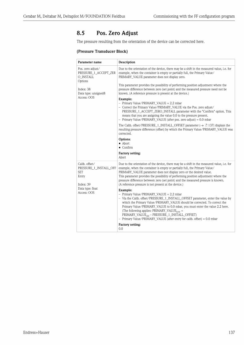
Cerabar M, Deltabar M, Deltapilot M/FOUNDATION Fieldbus Commissioning with the FF configuration program
Endress+Hauser 137
8.5 Pos. Zero Adjust
The pressure resulting from the orientation of the device can be corrected here.
(Pressure Transducer Block)
Parameter name Description
Pos. zero adjust/
PRESSURE_1_ACCEPT_ZER
O_INSTALL
Options
Index: 38
Data type: unsigned8
Access: OOS
Due to the orientation of the device, there may be a shift in the measured value, i.e. for
example, when the container is empty or partially full, the Primary Value/
PRIMARY_VALUE parameter does not display zero.
This parameter provides the possibility of performing position adjustment where the
pressure difference between zero (set point) and the measured pressure need not be
known. (A reference pressure is present at the device.)
Example:
– Primary Value/PRIMARY_VALUE = 2.2 mbar
– Correct the Primary Value/PRIMARY_VALUE via the Pos. zero adjust/
PRESSURE_1_ACCEPT_ZERO_INSTALL parameter with the "Confirm" option. This
means that you are assigning the value 0.0 to the pressure present.
– Primary Value/PRIMARY_VALUE (after pos. zero adjust) = 0.0 mbar
The Calib. offset/PRESSURE_1_INSTALL_OFFSET parameter ( ä 137) displays the
resulting pressure difference (offset) by which the Primary Value/PRIMARY_VALUE was
corrected.
Options:
• Abort
• Confirm
Factory setting:
Abort
Calib. offset/
PRESSURE_1_INSTALL_OFF
SET
Entry
Index: 39
Data type: float
Access: OOS
Due to the orientation of the device, there may be a shift in the measured value, i.e. for
example, when the container is empty or partially full, the Primary Value/
PRIMARY_VALUE parameter does not display zero or the desired value.
This parameter provides the possibility of performing position adjustment where the
pressure difference between zero (set point) and the measured pressure is known.
(A reference pressure is not present at the device.)
Example:
– Primary Value/PRIMARY_VALUE = 2.2 mbar
– Via the Calib. offset/PRESSURE_1_INSTALL_OFFSET parameter, enter the value by
which the Primary Value/PRIMARY_VALUE should be corrected. To correct the
Primary Value/PRIMARY_VALUE to 0.0 mbar, you must enter the value 2.2 here.
(The following applies: PRIMARY_VALUEnew =
PRIMARY_VALUEold – PRESSURE_1_INSTALL_OFFSET)
– Primary Value/PRIMARY_VALUE (after entry for calib. offset) = 0.0 mbar
Factory setting:
0.0

Commissioning with the FF configuration program Cerabar M, Deltabar M, Deltapilot M/FOUNDATION Fieldbus
138 Endress+Hauser
8.6 Pressure measurement
In this chapter the parameter text as well as the parameter name are indicated.
In FF configuration programs only the parameter text is displayed (exception: in the NI-FBUS
configurator you can select if the parameter text or the parameter name is displayed).
P01-xxxxxxxx-07-xx-xx-en-001
! Note!
• The Cerabar M and the Deltabar M are configured for the pressure measuring mode as standard.
The Deltapilot M is configured for the level measuring mode as standard. The measuring range
and the unit in which the measured value is transmitted, as well as the digital output value of the
Analog Input Block OUT, correspond to the data on the nameplate.
• For a description of the parameters mentioned, see
– ä 170, Pressure Transducer Block
– ä 199, Analog Input Block.
! Note!
• You can select another pressure unit by means of the Calibration Units/CAL_UNIT ( ä 136)
parameter. You can also specify a customer-specific unit by means of this parameter.
Parametertext Parametername
Linearization/LINEARIZATION
Description
1 Deltabar M: Before configuring the device for your
application, the pressure piping must be cleaned and the
device filled with medium.
2 Open the Pressure Transducer Block and set the block
mode to OOS.
3 Select the measuring mode if necessary:
• Depending on the sensor, select the "Differential
pressure", "Gauge pressure" or "Absolute pressure"
option by means of the Primary Value Type/
PRIMARY_VALUE_TYPE parameter.
4 Set the Pressure Transducer Block to the "Auto" block
mode.
5 If necessary, configure the Channel/CHANNEL
( ä 202), Linearization Type/L_TYPE ( ä 203),
Transducer Scale/XD_SCALE ( ä 201) and Output
Scale/OUT_SCALE ( ä 202) parameters by means of
the Analog Input Block.
6 Result:
The device is ready for pressure measurement.

Cerabar M, Deltabar M, Deltapilot M/FOUNDATION Fieldbus Commissioning with the FF configuration program
Endress+Hauser 139
8.7 Level measurement
In this chapter the parameter text as well as the parameter name are indicated.
In FF configuration programs only the parameter text is displayed (exception: in the NI-FBUS
configurator you can select if the parameter text or the parameter name is displayed).
P01-xxxxxxxx-07-xx-xx-en-001
8.7.1 Information on level measurement
! Note!
You have a choice of two methods for calculating the level: "In pressure" and "In height". The table
in the "Overview of level measurement" section that follows provides you with an overview of these
two measuring tasks.
• The limit values are not checked, i.e. the values entered must be appropriate for the sensor and
the measuring task for the device to be able to measure correctly.
• Customer-specific units are not possible.
• There is no unit conversion.
• The values entered for "Empty calib. (028)/Full calib. (031)", "Empty pressure (029)/Full
pressure (032)", "Empty height (030)/Full height (033)" must be at least 1 % apart. The value will
be rejected, and a warning message displayed, if the values are too close together.
8.7.2 Overview of level measurement
Parametertext Parametername
Linearization/LINEARIZATION
Measuring task Level
selection
Measured
variable options
Description Measured value
display
Calibration is
performed by entering
two pressure-level
value pairs.
"In pressure" Via the "Unit before
lin. (025)"
parameter: %, level,
volume or mass
units.
– Calibration with reference
pressure (wet calibration),
see ä 69
– Calibration without
reference pressure (dry
calibration), see ä 71
The measured value
display and the
"Level before lin. (019)"
parameter display the
measured value.
Calibration is
performed by entering
the density and two
height-level value
pairs.
"In height" – Calibration with reference
pressure (wet calibration),
see ä 75
– Calibration without
reference pressure (dry
calibration), see ä 73

Commissioning with the FF configuration program Cerabar M, Deltabar M, Deltapilot M/FOUNDATION Fieldbus
140 Endress+Hauser
8.7.3 "In pressure" level selection
Calibration with reference pressure – wet calibration
Example:
In this example, the level in a tank should be measured in "m". The maximum level is 3 m. The
pressure range is set to 0 to 300 mbar.
Prerequisite:
• The measured variable is in direct proportion to the pressure.
• The tank can be filled and emptied.
! Note!
• The values entered for Empty calibration/LOW_LEVEL_EASY and Full calib./
HIGH_LEVEL_EASY must be at least 1% apart for the "Level easy pressure" level mode. The value
will be rejected, and a warning message displayed, if the values are too close together. Further
limit values are not checked; i.e. the values entered must be appropriate for the sensor and the
measuring task so that the measuring device can measure correctly.
• Due to the orientation of the device, there may be a shift in the measured value, i.e. when the
container is empty, the Primary Value/PRIMARY_VALUE does not display zero.
For information on how to perform position adjustment, see also ä 137,
"Pos. zero adjust/PRESSURE_1_ACCEPT_ZERO_INSTALL".
Description
1 Deltabar M: Before configuring the device for your
application, the pressure piping must be cleaned and
filled with medium.
P01-Mxxxxxxx-19-xx-xx-xx-003
Fig. 37: Calibration with reference pressure –
wet calibration
1 See Table, Step 7.
2 See Table, Step 9.
2 Open the Pressure Transducer Block and set the block
mode to OOS.
➀
➁
0 mbar
300 mbar3 m
0 m

Cerabar M, Deltabar M, Deltapilot M/FOUNDATION Fieldbus Commissioning with the FF configuration program
Endress+Hauser 141
3 Select the measuring mode if necessary:
• Select the "Level" option by means of the Primary
Value Type/PRIMARY_VALUE_TYPE parameter. Or:
P01-xxxxxxxx-05-xx-xx-xx-011
Fig. 38: Calibration with reference pressure –
wet calibration
1 See Table, Step 8.
2 See Table, Step 9.
4 Select the "In pressure" option via the Level selection/
LEVEL_ADJUSTMENT parameter.
5 By means of the "Units index" Scale Out/SCALE_OUT
parameter, select the "m" option.
Or select a level unit by means of the Unit before Lin./
OUT_UNIT_EASY parameter, here "m" for example.
6 Select the "Wet" option by means of the Calibration
mode/LEVEL_ADJUST_MODE_EASY parameter.
7 Fill the container up to the lower level point.
The associated pressure value can be viewed by means of
the Meas. pressure/PRESSURE_1_FINAL_VALUE
parameter.
8 By means of the Scale Out/SCALE_OUT1) record
parameter, "EU at 0%/
E_ENGINERING_UNIT_0_PERCENT" elements, enter
a level value, here 0 m for example.
Or enter a level value via the Empty calibration/
LOW_LEVEL_EASY parameter, here 0 m for example.
9 Fill the container up to the upper level point.
The associated pressure value can be viewed by means of
the Meas. pressure/PRESSURE_1_FINAL_VALUE
parameter.
10 By means of the Scale Out/SCALE_OUT) record
parameter, "EU at 100%/
E_ENGINERING_UNIT_100_PERCENT" elements,
enter a level value, here 3 m for example.
Or enter a level value via the Full calib./
HIGH_LEVEL_EASY parameter, here 3 m for example.
11 Set the Pressure Transducer Block to the "Auto" block
mode.
12 If necessary, configure the
Channel/CHANNEL ( ä 202),
Linearization Type/L_TYPE ( ä 203),
Transducer Scale/XD_SCALE ( ä 201) and
Output Scale/OUT_SCALE ( ä 202) parameters by
means of the Analog Input Block.
1) Is only supported by host systems that permit write access to individual elements of the record.
Description
3
0
h[m]
0 300 p[mbar]
➀
➁

Commissioning with the FF configuration program Cerabar M, Deltabar M, Deltapilot M/FOUNDATION Fieldbus
142 Endress+Hauser
Calibration without reference pressure – dry calibration
Example:
In this example, the volume in a tank should be measured in liters. The maximum volume of
1000 liters corresponds to a pressure of 450 mbar. The minimum volume of 0 liters corresponds to
a pressure of 50 mbar since the device is mounted below the level lower-range value.
Prerequisite:
• The measured variable is in direct proportion to the pressure.
• This is a theoretical calibration i.e. the pressure and volume values for the lower and upper
calibration point must be known.
! Note!
• The values entered for Empty calibration/LOW_LEVEL_EASY and Full calib./
HIGH_LEVEL_EASY must be at least 1% apart for the "Level easy pressure" level mode. The value
will be rejected, and a warning message displayed, if the values are too close together. Further
limit values are not checked; i.e. the values entered must be appropriate for the sensor and the
measuring task so that the measuring device can measure correctly.
• Due to the orientation of the device, there may be a shift in the measured value, i.e. when the
container is empty, the Primary Value/PRIMARY_VALUE parameter does not display zero.
For information on how to perform position adjustment, see also ä 137,
"Pos. zero adjust/PRESSURE_1_ACCEPT_ZERO_INSTALL".
Description
1 Deltabar M: Before configuring the device for your
application, the pressure piping must be cleaned and
filled with medium.
P01-Mxxxxxxx-19-xx-xx-xx-004
Fig. 39: Calibration without reference pressure –
dry calibration
1 See Table, Step 9.
2 See Table, Step 8.
2 Open the Pressure Transducer Block and set the block
mode to OOS.
1000 l
50 mbar
450 mbar
0 l
� = 1 gcm3
1
2

Cerabar M, Deltabar M, Deltapilot M/FOUNDATION Fieldbus Commissioning with the FF configuration program
Endress+Hauser 143
3 Select the measuring mode if necessary:
Select the "Level" option via the Primary Value Type/
PRIMARY_VALUE_TYPE parameter. Or:
P01-xxxxxxxx-05-xx-xx-xx-026
Fig. 40: Calibration with reference pressure –
wet calibration
1 See Table, Step 6.
2 See Table, Step 7.
3 See Table, Step 8.
4 See Table, Step 9.
4 Select the "Level" measuring mode via the Measuring
mode/OPERATING_MODE parameter. Select the "In
pressure" option via the Level selection/
LEVEL_ADJUSTMENT parameter.
5 Select the "l" (liter) option via the "Units Index" Scale
Out/SCALE_OUT parameter.
Or select a volume unit via the Unit before Lin./
OUT_UNIT_EASY parameter, here "l" for example.
6 Select the "Dry" option via the Calibration mode/
LEVEL_ADJUST_MODE_EASY parameter
7 By means of the Scale In/SCALE_IN record parameter,
"Set URV/E_PRESSURE_UPPER_RANGE_VALUE"
elements, enter a pressure value, here 450 mbar for
example, or enter a pressure via the Full pressure/
HIGH_LEVEL_PRESSURE_EASY parameter, here
450 mbar for example.
8 By means of the Scale In/SCALE_IN record parameter,
"Set LRV/E_PRESSURE_LOWER_RANGE_VALUE",
enter a pressure value, here 50 mbar for example, or
enter a pressure via the Empty pressure/
LOW_LEVEL_PRESSURE_EASY parameter, here
50 mbar for example.
9 By means of the Scale Out/SCALE_OUT record
parameter, "EU at 100%/
E_ENGINERING_UNIT_100_PERCENT" elements,
enter the tank volume, here 1000 l for example.
Or enter a volume via the Full calib./
HIGH_LEVEL_EASY parameter, here 1000 l for
example.
10 By means of the Scale Out/SCALE_OUT record
parameter, "EU at 0%/
E_ENGINERING_UNIT_0_PERCENT" elements, enter
the tank volume, here 0 l for example.
Or enter a volume via the Empty calibration/
LOW_LEVEL_EASY parameter, here 0 l for example.
11 Set the Pressure Transducer Block to the "Auto" block
mode.
12 If necessary, configure
Channel/CHANNEL ( ä 202),
Linearization Type/L_TYPE ( ä 203),
Transducer Scale/XD_SCALE ( ä 201) and
Output Scale/OUT_SCALE ( ä 202) parameters by
means of the Analog Input Block.
Description
1000
0
V[l]
50 450 p[mbar]
➀
➁
➂
➃

Commissioning with the FF configuration program Cerabar M, Deltabar M, Deltapilot M/FOUNDATION Fieldbus
144 Endress+Hauser
8.7.4 "In height" level selection
Calibration with reference pressure – wet calibration
Example:
In this example, the volume in a tank should be measured in liters. The maximum volume of
1000 liters corresponds to a level of 4.5 m. The minimum volume of 0 liters corresponds to a level
of 0.5 m since the device is mounted below the level lower-range value. The density of the medium
is 1 g/cm3.
Prerequisite:
• The measured variable is in direct proportion to the pressure.
• The tank can be filled and emptied.
! Note!
• The values entered for Empty calibration/LOW_LEVEL_EASY and Full calib./
HIGH_LEVEL_EASY must be at least 1% apart for the "Level easy pressure" level mode. The value
will be rejected, and a warning message displayed, if the values are too close together. Further
limit values are not checked; i.e. the values entered must be appropriate for the sensor and the
measuring task so that the measuring device can measure correctly.
• Due to the orientation of the device, there may be a shift in the measured value, i.e. when the
container is empty, the Primary Value/PRIMARY_VALUE parameter does not display zero.
For information on how to perform position adjustment, see also ä 137,
"Pos. zero adjust/PRESSURE_1_ACCEPT_ZERO_INSTALL".
Description
1 Deltabar M: Before configuring the device for your
application, the pressure piping must be cleaned and
filled with medium.
P01-Mxxxxxxx-19-xx-xx-xx-007
Fig. 41: Calibration with reference pressure –
wet calibration
1 See Table, Step 8.
2 See Table, Step 10.
3 See Table, Step 12.
2 Open the Pressure Transducer Block and set the block
mode to OOS.
1000 l
0,5 m
4,5 m
0 l
� = 1 gcm3
1
3
2

Cerabar M, Deltabar M, Deltapilot M/FOUNDATION Fieldbus Commissioning with the FF configuration program
Endress+Hauser 145
3 Select the measuring mode if necessary:
Select the "Level height" option via the Primary Value
Type/PRIMARY_VALUE_TYPE parameter. Or:
P01-xxxxxxxx-05-xx-xx-xx-029
P01-xxxxxxxx-05-xx-xx-xx-030
Fig. 42: Calibration with reference pressure –
wet calibration
1 See Table, Step 8.
2 See Table, Step 10.
3 See Table, Step 12.
4 Select the "Level" measuring mode via the Measuring
mode/OPERATING_MODE parameter.
Select the "In height" option via the Level selection/
LEVEL_ADJUSTMENT parameter.
5 Select the "l" (liter) option via the "Units index" Scale
Out/SCALE_OUT parameter, or select a volume unit via
the Unit before Lin./OUT_UNIT_EASY parameter, here
"l" for example.
6 Select a height unit by means of the Height unit/
HEIGHT_UNIT_EASY parameter, here "m" for example.
7 Select the "Wet" option by means of the Calibration
mode/LEVEL_ADJUST_MODE_EASY parameter.
8 Enter a density by means of the Adjust density/
LEVEL_ADJUST_DENSITY_EASY parameter, here
"1" g/cm3 for example.
9 Fill the container up to the lower level point.
The associated level value can be viewed by means of
the Meas. level/MEASURED_ACTUAL_LEVEL_EASY
parameter.
10 By means of the Empty calibration/LOW_LEVEL_EASY
parameter, enter a value, here 0 "l" for example.
11 Fill the container up to the upper level point.
The associated level value can be viewed by means of
the Meas. level/MEASURED_ACTUAL_LEVEL_EASY
parameter.
12 By means of the Full calib./HIGH_LEVEL_EASY
parameter, enter a value, here 1000 "l" for example.
13 Set the Pressure Transducer Block to the "Auto" block
mode.
14 If necessary, configure the
Channel/CHANNEL ( ä 202),
Linearization Type/L_TYPE ( ä 203),
Transducer Scale/XD_SCALE ( ä 201) and
Output Scale/OUT_SCALE ( ä 202) parameters by
means of the Analog Input Block.
Description
4.5
0.5
h[m]
49 441 p[mbar]
h =p
� · g
� = 1g
cm3
➀
1000
0
V[l]
0.5 4.5➁
➂
h =p
ρ · g
h[m]

Commissioning with the FF configuration program Cerabar M, Deltabar M, Deltapilot M/FOUNDATION Fieldbus
146 Endress+Hauser
Calibration without reference pressure – dry calibration
Example:
In this example, the volume in a tank should be measured in liters. The maximum volume of
1000 liters corresponds to a level of 4.5 m. The minimum volume of 0 liters corresponds to a level
of 0.5 m since the device is mounted below the level lower-range value. The density of the medium
is 1 g/cm3.
Prerequisite:
• The measured variable is in direct proportion to the pressure.
• This is a theoretical calibration i.e. the height and volume values for the lower and upper
calibration point must be known.
! Note!
• The values entered for Empty calibration/LOW_LEVEL_EASY and Full calib./
HIGH_LEVEL_EASY must be at least 1 % apart for the "Level easy pressure" level mode. The
value will be rejected, and a warning message displayed, if the values are too close together.
Further limit values are not checked; i.e. the values entered must be appropriate for the sensor
and the measuring task so that the measuring device can measure correctly.
• Due to the orientation of the device, there may be a shift in the measured value, i.e. when the
container is empty, the Primary Value/PRIMARY_VALUE parameter does not display zero.
For information on how to perform position adjustment, see also ä 137,
"Pos. zero adjust/PRESSURE_1_ACCEPT_ZERO_INSTALL".
Description
1 Deltabar M: Before configuring the device for your
application, the pressure piping must be cleaned and
filled with medium.
P01-PMC71xxx-19-xx-xx-xx-009
Fig. 43: Calibration without reference pressure –
dry calibration
1 See Table, Step 8.
2 See Table, Steps 10 and 11.
3 See Table, Steps 12 and 13.
2 Open the Pressure Transducer Block and set the block
mode to OOS.
1000 l
0,5 m
4,5 m
0 l
� = 1 gcm3
1
3
2

Cerabar M, Deltabar M, Deltapilot M/FOUNDATION Fieldbus Commissioning with the FF configuration program
Endress+Hauser 147
3 Select the measuring mode if necessary:
Select the "Level height" option via the Primary Value
Type/PRIMARY_VALUE_TYPE parameter. Or:
P01-xxxxxxxx-05-xx-xx-xx-029
P01-xxxxxxxx-05-xx-xx-xx-032
Fig. 44: Calibration with reference pressure –
wet calibration
1 See Table, Step 8.
2 See Table, Step 9.
3 See Table, Step 10.
4 See Table, Step 11.
5 See Table, Step 12.
4 Select the "Level" measuring mode via the Measuring
mode/OPERATING_MODE parameter.
Select the "In height" option via the Level selection/
LEVEL_ADJUSTMENT parameter.
5 By means of the Unit before Lin./OUT_UNIT_EASY
parameter, select a volume unit, here "l" for example.
6 Select a height unit by means of the Height unit/
HEIGHT_UNIT_EASY parameter, here "m" for example.
7 Select the "Dry" option via the Calibration mode/
LEVEL_ADJUST_MODE_EASY parameter
8 By means of the Adjust density/
LEVEL_ADJUST_DENSITY_EASY parameter, enter a
density, here "1" "g/cm3" for example.
9 By means of the Empty calibration/LOW_LEVEL_EASY
parameter, enter a volume, here 0 l for example.
10 By means of the Empty height/ LEVEL_OFFSET_EASY
parameter, enter a height, here 0.5 m for example.
11 By means of the Full calib./HIGH_LEVEL_EASY
parameter, enter a volume, here 1000 l for example.
12 By means of the Full height/
LEVEL_100_PERCENT_EASY parameter, enter a height,
here 4.5 m for example.
13 Set the Pressure Transducer Block to the "Auto" block
mode.
14 If necessary, configure the
Channel/CHANNEL ( ä 202),
Linearization Type/L_TYPE ( ä 203),
Transducer Scale/XD_SCALE ( ä 201) and
Output Scale/OUT_SCALE ( ä 202) parameters by
means of the Analog Input Block.
Description
4.5
0.5
h[m]
49 441 p[mbar]
h =p
� · g
� = 1g
cm3
➀
1000
0
V[l]
0.5 4.5➁
➂
h =p
ρ · g
h[m]
➃
➄
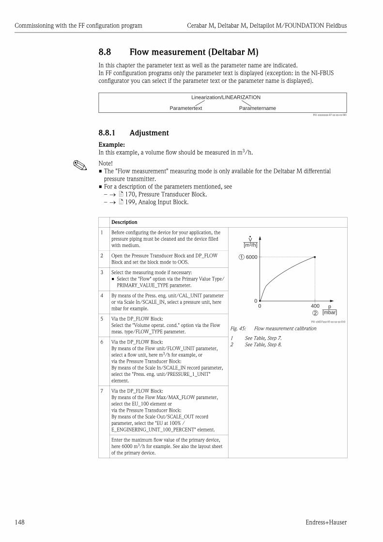
Commissioning with the FF configuration program Cerabar M, Deltabar M, Deltapilot M/FOUNDATION Fieldbus
148 Endress+Hauser
8.8 Flow measurement (Deltabar M)
In this chapter the parameter text as well as the parameter name are indicated.
In FF configuration programs only the parameter text is displayed (exception: in the NI-FBUS
configurator you can select if the parameter text or the parameter name is displayed).
P01-xxxxxxxx-07-xx-xx-en-001
8.8.1 Adjustment
Example:
In this example, a volume flow should be measured in m3/h.
! Note!
• The "Flow measurement" measuring mode is only available for the Deltabar M differential
pressure transmitter.
• For a description of the parameters mentioned, see
– ä 170, Pressure Transducer Block.
– ä 199, Analog Input Block.
Parametertext Parametername
Linearization/LINEARIZATION
Description
1 Before configuring the device for your application, the
pressure piping must be cleaned and the device filled
with medium.
P01-xMD7xxx-05-xx-xx-xx-010
Fig. 45: Flow measurement calibration
1 See Table, Step 7.
2 See Table, Step 8.
2 Open the Pressure Transducer Block and DP_FLOW
Block and set the block mode to OOS.
3 Select the measuring mode if necessary:
• Select the "Flow" option via the Primary Value Type/
PRIMARY_VALUE_TYPE parameter.
4 By means of the Press. eng. unit/CAL_UNIT parameter
or via Scale In/SCALE_IN, select a pressure unit, here
mbar for example.
5 Via the DP_FLOW Block:
Select the "Volume operat. cond." option via the Flow
meas. type/FLOW_TYPE parameter.
6 Via the DP_FLOW Block:
By means of the Flow unit/FLOW_UNIT parameter,
select a flow unit, here m3/h for example, or
via the Pressure Transducer Block:
By means of the Scale In/SCALE_IN record parameter,
select the "Press. eng. unit/PRESSURE_1_UNIT"
element.
7 Via the DP_FLOW Block:
By means of the Flow Max/MAX_FLOW parameter,
select the EU_100 element or
via the Pressure Transducer Block:
By means of the Scale Out/SCALE_OUT record
parameter, select the "EU at 100% /
E_ENGINERING_UNIT_100_PERCENT" element.
Enter the maximum flow value of the primary device,
here 6000 m3/h for example. See also the layout sheet
of the primary device.
➀
p[mbar]➁
6000
00 400
[m /h]3V

Cerabar M, Deltabar M, Deltapilot M/FOUNDATION Fieldbus Commissioning with the FF configuration program
Endress+Hauser 149
! Note!
1. By means of the Flow meas. type/FLOW_TYPE ( ä 186) parameter, you can choose
between the following flow types:
– Volume process cond. (volume under operating conditions)
– Gas norm. cond. (norm volume under norm conditions in Europe: 1013.25 mbar and
273.15 K (0 °C))
– Gas std. cond. (standard volume under standard conditions in USA: 1013.25 mbar (14.7 psi)
and 288. 15 K (15 °C/59 °F))
– Mass p. cond. (mass under operating conditions)
2. The unit selected via the Flow unit/FLOW_UNIT ( ä 187) parameter must be appropriate
for the chosen flow type (Flow meas. type/FLOW_TYPE, ä 186).
3. In the lower measuring range, small flow quantities (creepages) can lead to large fluctuations
in the measured value. By means of the Set. L. Fl. Cut-off/
CREEP_FLOW_SUPRESSION_OFF_THRES ( ä 188) parameter, you can configure a low
flow cut off.
Description
8 Via the DP_FLOW Block:
Select via the Max. press. flow/
FLOW_MAX_PRESSURE parameter or
via the Pressure Transducer Block:
By means of the Scal In/SCALE_IN record parameter,
select the "Set URV/
E_PRESSURE_UPPER_RANGE_VALUE" element.
Enter the maximum pressure, here 400 mbar for
example. See also the layout sheet of the primary device.
9 Set the Pressure Transducer Block and DP_FLOW Block
to the "Auto" block mode.
10 If necessary, configure the
Channel/CHANNEL ( ä 202),
Linearization Type/L_TYPE ( ä 203),
Transducer Scale/XD_SCALE ( ä 201) and
Output Scale/OUT_SCALE ( ä 202) parameters by
means of the Analog Input Block.
11 Result:
The device is configured for flow measurement.

Commissioning with the FF configuration program Cerabar M, Deltabar M, Deltapilot M/FOUNDATION Fieldbus
150 Endress+Hauser
8.8.2 Totalizer
Example:
In this example, the volume flow should be totalized and displayed in the unit m3E3. Negative flows
should be added to the flow rate.
! Note!
• For a description of the parameters mentioned, see
– ä 186, DP_FLOW Transducer Block
– ä 199, Analog Input Block.
• Totalizer 1 can be reset. Totalizer 2 cannot be reset.
! Note!
You can use the Display mode/DISPLAY_MAIN_LINE_1_CONTENT parameter ( ä 193) to
specify which measured value should be displayed on the local operation.
Description
1 Calibrate the device in accordance with Section 8.8.1.
2 Open the DP_FLOW Transducer Block and set the block
mode to OOS.
3 By means of the Eng. unit total. 1/TOTALIZER_1_UNIT
parameter, select a flow unit, here m3 E3 for example.
4 By means of the Totalizer 1 mode/
TOTALIZER_1_MODE parameter, specify the totalizing
mode for negative flows, here the "Only negative flow"
option for example.
5 Use the Reset Totalizer 1/TOTALIZER_1_RESET
parameter to reset to zero.
6 Result:
The Totalizer 1/TOTALIZER_1_STRING_VALUE record
parameter, 1/E_TOTALIZER_1_FLOAT totalizer
element displays the totalized volume flow.
7 Set the DP_FLOW Block to "Auto".

Cerabar M, Deltabar M, Deltapilot M/FOUNDATION Fieldbus Commissioning with the FF configuration program
Endress+Hauser 151
Resetting totalizer 1 automatically
By means the Analog Alarm Block
With the aid of the Analog Alarm and Discrete Output Block, totalizer 1 in the DP_Flow Transducer
Block can be reset automatically.
P01-xxxxxxxx-02-xx-xx-en-003
The DP_FLOW Transducer Block is connected to an Analog Input Block by means of the Channel/
CHANNEL parameter (Channel/CHANNEL = 6). In the Analog Alarm Block the High High Limit/
HI_HI_LIM parameter is used to set a limit value at which the totalizer should be reset to zero. As
soon as this limit value is overshot, the Analog Alarm Block transmits an alarm value to the
downstream Discrete Output Block. The latter changes its output from 0 to 1 and thus resets the
totalizer in the DP_FLOW Transducer Block to 0. The output of the Analog Alarm Block changes
back to 0.
By means the Analog Input Block
With the aid of Analog Input and Discrete Output Block, totalizer 1 in the DP_Flow Transducer
Block can be reset automatically.
P01-xxxxxxxx-02-xx-xx-en-004
The DP_FLOW Transducer Block is connected to an Analog Input Block by means of the Channel/
CHANNEL parameter (Channel/CHANNEL = 6). In the Analog Input Block the High High Limit/
HI_HI_LIM parameter is used to set a limit value at which the totalizer should be reset to zero. As
soon as this limit value is overshot, the Analog Input Block transmits an alarm value to the
downstream Discrete Output Block. The latter changes its output from 0 to 1 and thus resets the
totalizer in the DP_FLOW Transducer Block to 0. The output of the Analog Input Block changes
back to 0.
Analog Input Block 3CHANNEL = 6L_TYPE = Direct
DP FlowTransducer Block
Analog AlarmBlock
Discrete OutputBlockCHANNEL = 21
HI_HI_ALM
OU
T_
AL
M
IN CA
S_
IN_
D
OU
T_
D
OU
T
HI_HI_LIM
TO
TA
LIZ
ER
_1
_V
AL
UE
/T
OTA
LIZ
ER
1
Analog Input Block 3CHANNEL = 6L_TYPE = Direct
DP FlowTransducer Block
Discrete OutputBlockCHANNEL = 21
IN OU
T_D
HIH
I_A
LM
_O
UT
_D
TO
TA
LIZ
ER
_1_
VA
LU
E/
TO
TA
LIZ
ER
1
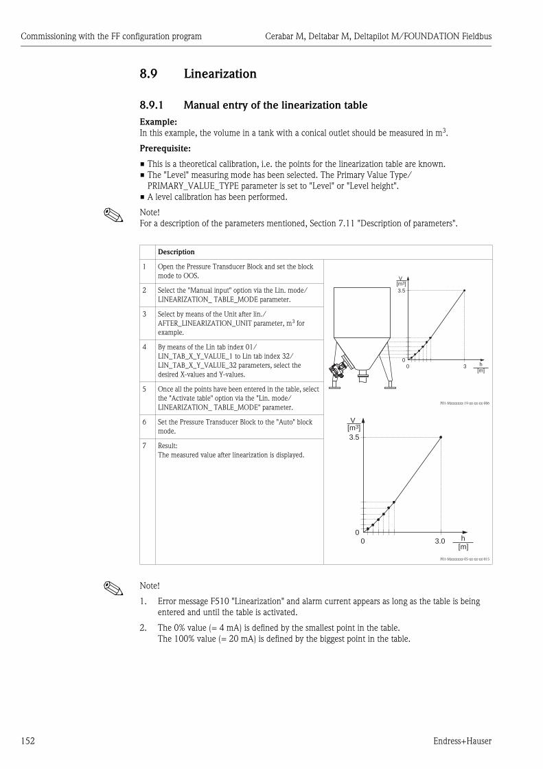
Commissioning with the FF configuration program Cerabar M, Deltabar M, Deltapilot M/FOUNDATION Fieldbus
152 Endress+Hauser
8.9 Linearization
8.9.1 Manual entry of the linearization table
Example:
In this example, the volume in a tank with a conical outlet should be measured in m3.
Prerequisite:
• This is a theoretical calibration, i.e. the points for the linearization table are known.
• The "Level" measuring mode has been selected. The Primary Value Type/
PRIMARY_VALUE_TYPE parameter is set to "Level" or "Level height".
• A level calibration has been performed.
! Note!
For a description of the parameters mentioned, Section 7.11 "Description of parameters".
! Note!
1. Error message F510 "Linearization" and alarm current appears as long as the table is being
entered and until the table is activated.
2. The 0% value (= 4 mA) is defined by the smallest point in the table.
The 100% value (= 20 mA) is defined by the biggest point in the table.
Description
1 Open the Pressure Transducer Block and set the block
mode to OOS.
P01-Mxxxxxxx-19-xx-xx-xx-006
P01-Mxxxxxxx-05-xx-xx-xx-015
2 Select the "Manual input" option via the Lin. mode/
LINEARIZATION_ TABLE_MODE parameter.
3 Select by means of the Unit after lin./
AFTER_LINEARIZATION_UNIT parameter, m3 for
example.
4 By means of the Lin tab index 01/
LIN_TAB_X_Y_VALUE_1 to Lin tab index 32/
LIN_TAB_X_Y_VALUE_32 parameters, select the
desired X-values and Y-values.
5 Once all the points have been entered in the table, select
the "Activate table" option via the "Lin. mode/
LINEARIZATION_ TABLE_MODE" parameter.
6 Set the Pressure Transducer Block to the "Auto" block
mode.
7 Result:
The measured value after linearization is displayed.
3.5
00 3
V[m ]3
h[m]
3.5
00 3.0
V[m ]3
h[m]

Cerabar M, Deltabar M, Deltapilot M/FOUNDATION Fieldbus Commissioning with the FF configuration program
Endress+Hauser 153
8.9.2 Semi-automatic entry of the linearization table
Example:
In this example, the volume in a tank with a conical outlet should be measured in m3.
Prerequisite:
• The tank can be filled or emptied. The linearization characteristic must rise continuously.
• The "Level" measuring mode has been selected. The Primary Value Type/
PRIMARY_VALUE_TYPE parameter is set to "Level" or "Level height".
! Note!
For a description of the parameters mentioned Chap. 7.11 "Description of parameters".
! Note!
Error message F510 "Linearization" appears as long as the table is being entered and until the table
is activated.
Description
1 Open the Pressure Transducer Block and set the block
mode to OOS.
P01-Mxxxxxxx-19-xx-xx-xx-006
P01-Mxxxxxxx-05-xx-xx-xx-015
2 Select the "Semi-auto. entry" option via the "Lin. mode/
LINEARIZATION_ TABLE_MODE" parameter.
3 By means of the Unit after lin./
AFTER_LINEARIZATION_UNIT parameter, select the
volume unit/mass unit, e.g. m3.
4 Fill the tank to the height of the 1st point.
5 By means of the Line numb./LINEARIZATION_
TABLE_INDEX parameter, enter the number of the
point in the table.
The actual level is displayed via the X-value:/
TB_LINEARIZATION_ TABLE_X_VALUE parameter.
Using the Y-value:/TB_LINEARIZATION_
TABLE_Y_VALUE parameter, enter the associated
volume value, here 0 m3 for example, and confirm the
value.
6 Enter the next point as explained in Step 5.
7 Once all the points have been entered in the table, select
the "Activate table" option via the "Lin. mode/
LINEARIZATION_ TABLE_MODE" parameter.
8 Set the Pressure Transducer Block to the "Auto" block
mode.
9 Result:
The measured value after linearization is displayed.
3.5
00 3
V[m ]3
h[m]
3.5
00 3.0
V[m ]3
h[m]

Commissioning with the FF configuration program Cerabar M, Deltabar M, Deltapilot M/FOUNDATION Fieldbus
154 Endress+Hauser
8.10 Electrical differential pressure measurement with
gauge pressure sensors (Cerabar M or Deltapilot M)
Example:
In the example given, two Cerabar M or Deltapilot M devices (each with a gauge pressure sensor)
are interconnected. The pressure difference can thus be measured using two independent
Cerabar M or Deltapilot M devices.
! Note!
For a description of the parameters mentioned Chap. 7.11 "Description of parameters".
P01-XMX5Xxx-14-xx-xx-xx-002
Fig. 46:
1 Shut-off valves
2 e.g. filter
1.)
2.)
The Analog Input Block output of the high-pressure side of the device has to be connected to one
of the 4 inputs of the Input Selector Block on the low-pressure side of the device (here Input1 for
example).
This configuration has to be written to the devices.
Both blocks must be set to the Auto mode.
Cerabar M/Deltapilot M
FF HOSTSystem
➀
➁
➀
➁
Cerabar M/Deltapilot M
Description
Adjustment of the Cerabar M/Deltapilot M on the high-pressure side in the Pressure Transducer Block
1 Open the Pressure Transducer Block and set the block mode to OOS.
2 Select the "Pressure" measuring mode via the Measuring mode/OPERATING_MODE or Primary Value Type/
PRIMARY_VALUE_TYPE parameter.
3 Select a pressure unit via the Calibration Units/CAL_UNIT parameter, here "mbar" for example.
4 The Cerabar M/Deltapilot M is unpressurized, perform position adjustment, see ä 67.
5 Set the Pressure Transducer Block to the "Auto" block mode. If necessary, configure the
Channel/CHANNEL ( ä 202),
Linearization Type/L_TYPE ( ä 203),
Transducer Scale/XD_SCALE ( ä 201) and
Output Scale/OUT_SCALE ( ä 202) parameters by means of the Analog Input Block.

Cerabar M, Deltabar M, Deltapilot M/FOUNDATION Fieldbus Commissioning with the FF configuration program
Endress+Hauser 155
P01-XMX5Xxx-14-xx-xx-en-003
3.)
! Note!
It is not permitted to reverse the assignment of the measuring points to the direction of
communication.
The measured value of the transmitting device must always be greater than the measured value of
the receiving device (via the "Electr. delta P" function).
Adjustments that result in an offset of the pressure values (e.g. position adjustment, trim) must
always be performed in accordance with the individual sensor and its orientation, irrespective of the
"Electr. Delta P" application. Other settings result in non-permitted use of the "Electr. Delta P"
function and can lead to incorrect measured values.
Description
Adjustment of the Cerabar M/Deltapilot M on the low-pressure side (the differential is generated in this
device) in the Pressure Transducer Block
1 Open the Pressure Transducer Block and set the block mode to OOS.
2 Select the "Pressure" measuring mode via the Measuring mode/OPERATING_MODE or Primary Value Type/
PRIMARY_VALUE_TYPE parameter.
3 Select a pressure unit via the Calibration Units/CAL_UNIT parameter, here "mbar" for example.
4 The Cerabar M/Deltapilot M is unpressurized, perform position adjustment, see ä 67.
5 Select the input via the E.delta p selec./E_DELTA_P_INPUT_SELECTOR parameter (here Input1 for example).
6 Select the desired unit via the E.delta p unit/E_DELTA_P_INPUT_UNIT parameter (here mbar for example).
7 Select the external value mode via the Electr. delta P/ELECTRIC_DELTA_P_CONTROL parameter.
8 The current measured values and status information returned by the device on the high-pressure side can be read
via the E. delta p value/E_DELTA_P_VALUE and "E. delta p status/E_DELTA_P_STATUS" parameters.
9 Set the Pressure Transducer Block to the "Auto" block mode. If necessary, configure the
Channel/CHANNEL ( ä 202),
Linearization Type/L_TYPE ( ä 203),
Transducer Scale/XD_SCALE ( ä 201) and
Output Scale/OUT_SCALE ( ä 202) parameters by means of the Analog Input Block.

Commissioning with the FF configuration program Cerabar M, Deltabar M, Deltapilot M/FOUNDATION Fieldbus
156 Endress+Hauser
8.11 Displaying external values on the onsite display via
FF bus
The inputs of the Input Selector Block are used to display external values on the onsite display via
the FF bus.
Example:
P01-Mxxxxxxx-19-xx-xx-xx-017
Fig. 47: Connection example
! Note!
The desired value must be connected to one of the four inputs of the Input Selector Block, and this
configuration must be written into the device. Only the inputs of the Input Selector Block are used
for functionality. Output and status are not taken into account
Description
1 Open the Display Block.
2 Select the "External value only" option via the Display mode/DISPLAY_MAIN_LINE_1_CONTENT parameter.
3 Select an input via the FF input source/DISPLAY_INPUT_SELECTOR parameter, here "Input 3" for example.
4 Via the FF input unit/DISPLAY_INPUT_UNIT parameter, select the appropriate unit, as only values and status
information are transmitted with FF, here "m²" for example.
5 Via the FF input form./DISPLAY_INPUT_FORMAT parameter, select the desired format for the onsite display, here
"x.xx" for example.

Cerabar M, Deltabar M, Deltapilot M/FOUNDATION Fieldbus Commissioning with the FF configuration program
Endress+Hauser 157
8.12 Description of parameters
In this chapter the parameter text as well as the parameter name are indicated.
In FF configuration programs only the parameter text is displayed (exception: in the NI-FBUS
configurator you can select if the parameter text or the parameter name is displayed).
P01-xxxxxxxx-07-xx-xx-en-001
! Note!
• With FOUNDATION Fieldbus, all the device parameters are categorized according to their
functional properties and task and are assigned to the Resource Block, the Transducer Blocks and
the function blocks. The parameters of the Resource Block, the Transducer Blocks and the Analog
Input Block are described in this section. For a parameter description of the other function blocks,
such as the PID or Discrete Output Block, see Operating Instructions BA00013S "FOUNDATION
Fieldbus Overview" or the FOUNDATION Fieldbus specification.
• Some parameters are only relevant if other parameters are appropriately configured.
8.12.1 Block model
The Cerabar M/Deltabar M/Deltapilot M has the following blocks:
• Resource Block (device block)
• Transducer Blocks
– Pressure Transducer Block
This block supplies the output variables Primary Value/PRIMARY_VALUE and Secondary
Value/SECONDARY_VALUE. It contains all the parameters to configure the measuring device
for the measuring task such as measuring mode selection, linearization function and unit
selection.
– DP_FLOW Transducer Block (only Deltabar M)
This block supplies the output variable "Totalizer 1 /TOTALIZER_1_FLOAT" and "Totalizer 2 /
TOTALIZER_2_FLOAT". It contains all the parameters that are needed to configure the flow
and this totalizer.
– Diagnostic Transducer Block
This Block returns error messages as output variables. It contains the simulation function for
the Pressure Transducer Block, parameters to configure the alarm response and the user limits
for pressure and temperature.
– Display Transducer Block
This Block does not return any output variables. It contains all the parameters for configuring
the onsite display, such as Language/DISPLAY_LANGUAGE.
• Function blocks
– 2 Analog Input Blocks (AI)
– Discrete Output Block (DO)
– PID Block (PID)
– Arithmetic Block (ARB)
– Input Selector Block (ISB)
– Integrator Block (IT)
– Discrete Input Block (DI)
Parametertext Parametername
Linearization/LINEARIZATION

Commissioning with the FF configuration program Cerabar M, Deltabar M, Deltapilot M/FOUNDATION Fieldbus
158 Endress+Hauser
Block configuration when device is delivered
The block model shown below illustrates the block configuration when the device is delivered.
P01-xMx5xxxx-02-xx-xx-en-000
Fig. 48: Block configuration when device is delivered
Cerabar M/Deltapilot M
The Pressure Transducer Block returns the primary value (measured value) and the secondary value
(sensor temperature). The Primary Value and Secondary Value are each transmitted to an Analog
Input Block via the Channel/CHANNEL parameter ( ä 202, Channel/CHANNEL parameter
description). The Discrete Output, Discrete Input, PID, Arithmetic, Input Selector and Integrator
are not connected in the as-delivered state. (IT, DI).
Deltabar M
The Pressure Transducer Block returns the Primary Value (measured value) and the Secondary
Value (max. pressure). In the DP_FLOW Transducer Block, the flow is totalized in the "Flow"
measuring mode and output by means of the Totalizer 1/TOTALIZER_1 and Totalizer 2/
TOTALIZER_2 record parameter. The Primary Value, Secondary Value and Totalizer 1 and 2 values
are each transmitted to an Analog Input Block via the Channel/CHANNEL parameter ( ä 202,
Channel/CHANNEL parameter description). The Discrete Output, PID, Arithmetic and Input
Selector are not connected in the as-delivered state. (IT, DI)
! Note!
Please note that links between the blocks are deleted and the FF parameters are reset to the default
values following a reset by means of the Restart/RESTART parameter in the Resource Block,
"Default" option.
PressureTransducer Block
Analog Input Block 1CHANNEL = 1L_TYPE = Direct
Analog Input Block 2CHANNEL = 2L_TYPE = Direct
Analog Input Block 2CHANNEL = 3L_TYPE = Direct
DP FlowTransducer Block
DisplayTransducer Block
DiagnosticTransducer Block
Primary value
Resource Block
IntegratorBlock
Discrete InputBlock
PID Block Input SelectorBlock
SignalCharacterizerBlock
Discrete OutputBlock
Arithmetic Block
Measured variable
SensorSignal evaluation
Displaywith scaling
Cerabar M / Deltapilot M:Secondary value =Sensor temperature
Deltabar M: measured pressure

Cerabar M, Deltabar M, Deltapilot M/FOUNDATION Fieldbus Commissioning with the FF configuration program
Endress+Hauser 159
8.12.2 Resource Block
Resource Block - standard parameters
Parameter Description
Static Revision/ST_REV
Display
Index: 1
Data type: unsigned16
Access: read only
Displays the counter for static parameters of the Resource Block.
The counter is incremented by one with each change of a static parameter of the Resource
Block. The counter counts up to 65535 and then starts again at zero.
Tag Description/
TAG_DESC
Entry
Index: 2
Data type: octet string
Access: wr for Auto, OOS
Enter a description for the related block or the measuring point e.g. TAG number
(max. 32 alphanumeric characters).
Strategy/STRATEGY
Entry
Index: 3
Data type: unsigned16
Access: wr for Auto, OOS
Enter user-specific value for grouping and thus faster evaluation of the blocks.
Grouping takes place by entering the same numerical value for the Strategy/STRATEGY
parameter of the block in question. This value is neither checked nor processed by the
Resource Block.
Input range:
0...65535
Factory setting:
0
Alert Key/ALERT_KEY
Entry
Index: 4
Data type: unsigned8
Access: wr for Auto, OOS
Enter the identification number for the measuring device or for each individual block.
The control level uses this identification number to sort alarm and event messages and
initiate other processing steps.
Input range:
1...255
Factory setting:
0
Block Mode/MODE_BLK
Selection, display
Index: 5
Data type: DS-69
Access: wr for Auto, OOS
The Block Mode/MODE_BLK parameter is a structured parameter consisting of four
elements. The Resource Block supports the "Auto" (automatic) and OOS (out of service)
modes.
TARGET
• Change the block mode.
ACTUAL
• Displays the current block mode.
PERMITTED
• Displays the modes supported by the block.
NORMAL
• Displays the block mode during standard operation.
Block Error/BLOCK_ERR
Display
Index: 6
Data type: bit string
Access: read only
Displays the active block error.
Possibilities:
• Out of service: the Resource Block is in the OOS block mode.
• Simulation active: DIP switch 3 "Simulation" on the electronic insert is set to "on",
i.e. simulation is possible.
Resource State/
RS_STATE
Display
Index: 7
Data type: unsigned8
Access: read only
Displays the current status of the Resource Block.
Possibilities:
• Standby: The Resource Block is in the OOS mode (out-of-service). The remaining blocks
cannot be executed.
• Online linking: The configured links between the function blocks have not yet been
established.
• Online: Standard block mode, the Resource Block operates in the auto mode. All the
configured links between the function blocks have been established. If a link is missing,
this parameter displays the "Online linking" status.

Commissioning with the FF configuration program Cerabar M, Deltabar M, Deltapilot M/FOUNDATION Fieldbus
160 Endress+Hauser
Test Read Write/
TEST_RW
Display
Index: 8
Data type: DS-85
Access: wr for Auto, OOS
This parameter is required only for the FF conformance test and has no meaning in normal
operation.
DD Resource/
DD_RESOURCE
Display
Index: 9
Data type: visible string
Access: read only
String that indicates the tag of the resource that contains the device description for this
resource.
Manufacturer ID/
MANUFAC_ID
Display
Index: 10
Data type: unsigned32
Access: read only
Displays the manufacturer's ID number.
Endress+Hauser: 0 x 452B48 (decimal: 4533064)
Device Type/DEV_TYPE
Display
Index: 11
Data type: unsigned16
Access: read only
Displays the device ID number.
Deltabar M 5x: hexadecimal: 0x1021, decimal: 4129.
Cerabar M 5x: hexadecimal: 0x1019, decimal: 4121.
Deltapilot M 5x: hexadecimal: 0x1023, decimal: 4131.
Device Revision/
DEV_REV
Display
Index: 12
Data type: unsigned8
Access: read only
Displays the revision number of the device.
DD Revision/DD_REV
Display
Index: 13
Data type: unsigned8
Access: read only
Displays the revision number of the device description (DD).
Grant Deny/
GRANT_DENY
Entry
Index: 14
Data type: DS-70
Access: wr for Auto, OOS
Grant or restrict access authorization for a fieldbus host system to the device. This parameter
is not evaluated by Deltabar M 5x, Cerabar M 5x and Deltapilot M 5x.
Hard Types/
HARD_TYPES
Display
Index: 15
Data type: bit string
Access: read only
Displays the input and output signal type.
Resource Block - standard parameters
Parameter Description
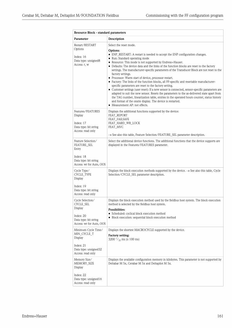
Cerabar M, Deltabar M, Deltapilot M/FOUNDATION Fieldbus Commissioning with the FF configuration program
Endress+Hauser 161
Restart/RESTART
Options
Index: 16
Data type: unsigned8
Access: r, w
Select the reset mode.
Options:
• ENP_RESTART: A restart is needed to accept the ENP configuration changes.
• Run: Standard operating mode
• Resource: This mode is not supported by Endress+Hauser.
• Defaults: The device data and the links of the function blocks are reset to the factory
settings. The manufacturer-specific parameters of the Transducer Block are not reset to the
factory settings.
• Processor: Warm start of device, processor restart.
• Factory: The links of the function blocks, all FF-specific and resettable manufacturer-
specific parameters are reset to the factory setting.
• Customer settings (user reset): If a new sensor is connected, sensor-specific parameters are
adapted to suit the new sensor. Resets the parameters to the as-delivered state apart from
the TAG number, linearization table, entries in the operated hours counter, status history
and format of the onsite display. The device is restarted.
• Measurement AP: not effects.
Features/FEATURES
Display
Index: 17
Data type: bit string
Access: read only
Displays the additional functions supported by the device:
FEAT_REPORT
FEAT_FAILSAFE
FEAT_HARD_WR_LOCK
FEAT_MVC
See also this table, Feature Selection/FEATURE_SEL parameter description.
Feature Selection/
FEATURE_SEL
Entry
Index: 18
Data type: bit string
Access: wr for Auto, OOS
Select the additional device functions. The additional functions that the device supports are
displayed in the Features/FEATURES parameter.
Cycle Type/
CYCLE_TYPE
Display
Index: 19
Data type: bit string
Access: read only
Displays the block execution methods supported by the device. See also this table, Cycle
Selection/CYCLE_SEL parameter description.
Cycle Selection/
CYCLE_SEL
Display
Index: 20
Data type: bit string
Access: wr for Auto, OOS
Displays the block execution method used by the fieldbus host system. The block execution
method is selected by the fieldbus host system.
Possibilities:
• Scheduled: cyclical block execution method
• Block execution: sequential block execution method
Minimum Cycle Time/
MIN_CYCLE_T
Display
Index: 21
Data type: unsigned32
Access: read only
Displays the shortest MACROCYCLE supported by the device.
Factory setting:
3200 1/32 ms ( 100 ms)
Memory Size/
MEMORY_SIZE
Display
Index: 22
Data type: unsigned16
Access: read only
Displays the available configuration memory in kilobytes. This parameter is not supported by
Deltabar M 5x, Cerabar M 5x and Deltapilot M 5x.
Resource Block - standard parameters
Parameter Description

Commissioning with the FF configuration program Cerabar M, Deltabar M, Deltapilot M/FOUNDATION Fieldbus
162 Endress+Hauser
Nonvolatile Cycle Time/
NV_CYCLE_T
Display
Index: 23
Data type: unsigned32
Access: read only
Displays the time interval for which the dynamic device parameters are stored in the
nonvolatile memory.
5760000 1/32 ms 180s
Free Space/FREE_SPACE
Display
Index: 24
Data type: float
Access: read only
Displays the system memory (in percent) available for the execution of further function
blocks. This parameter is not supported by Deltabar M, Cerabar M and Deltapilot M.
Free Time/FREE_TIME
Display
Index: 25
Data type: float
Access: read only
Displays the free system time (in percent) available for the execution of further function
blocks. This parameter is not supported by Deltabar M, Cerabar M and Deltapilot M.
Shed Remote Cascade/
SHED_RCAS
Entry
Index: 26
Data type: unsigned32
Access: wr for Auto, OOS
Enter the monitoring time for checking the connection between the fieldbus host system and
the PID function block in the RCAS block mode. On expiry of this monitoring time the PID
function block switches from the RCAS block mode to the block mode selected via the Shed
Options/SHED_OPT parameter.
Factory setting:
640000 1/32 ms
Shed Remote Out/
SHED_ROUT
Entry
Index: 27
Data type: unsigned32
Access: wr for Auto, OOS
Enter the monitoring time for checking the connection between the fieldbus host system and
the PID function block in the ROUT block mode. On expiry of this monitoring time the PID
function block switches from the ROUT block mode to the block mode selected via the Shed
Options/SHED_OPT parameter.
Factory setting:
640000 1/32 ms
Fault State/
FAULT_STATE
Display
Index: 28
Data type: unsigned8
Access: read only
Current status display of the fault state of the Discrete Output function block.
Possibilities:
• Uninitialized
• Clear (fault state not active)
• Active (fault state active)
Set Fault State/
SET_FSTATE
Options
Index: 29
Data type: unsigned8
Access: wr for Auto, OOS
Activate the fault state of the Discrete Output function block manually. See also this table,
Clear Fault State/CLR_FSTATE parameter description.
Possibilities:
• Uninitialized
• Off
• Set (the fault state is enabled)
Clear Fault State/
CLR_FSTATE
Options
Index: 30
Data type: unsigned8
Access: wr for Auto, OOS
Deactivate the fault state of the Discrete Output function block manually. See also this
table, Set Fault State/SET_FSTATE parameter description.
Possibilities:
• Uninitialized
• Off
• Clear (fault state is disabled)
Max Notify/
MAX_NOTIFY
Display
Index: 31
Data type: unsigned8
Access: read only
Displays the number of event reports supported by the device that can exist unconfirmed at
the same time. See also this table, Limit Notify/LIM_NOTIFY parameter description.
Resource Block - standard parameters
Parameter Description

Cerabar M, Deltabar M, Deltapilot M/FOUNDATION Fieldbus Commissioning with the FF configuration program
Endress+Hauser 163
Limit Notify/
LIM_NOTIFY
Entry
Index: 32
Data type: unsigned8
Access: wr for Auto, OOS
Enter the maximum possible number of event reports that can exist unconfirmed at the same
time. This parameter is not evaluated by Deltabar M 5x, Cerabar M 5x and Deltapilot M 5x.
Confirm Time/
CONFIRM_TIME
Entry
Index: 33
Data type: unsigned32
Access: wr for Auto, OOS
Enter the confirmation time for the event report. If the device does not receive confirmation
within this time, the event report is sent to the fieldbus host system again.
Factory setting:
640000 1/32 ms
Write Lock/
WRITE_LOCK
Display
Index: 34
Data type: unsigned8
Access: read only
Displays the status of DIP switch 1 on the electronic insert.
You can lock or unlock parameters relevant to the measured value with DIP switch 1. If
operation is locked by means of the Operator code/S_W_LOCK ( ä 194) parameter, you
can only unlock operation again by means of this parameter.
Possibilities:
• Locked: Security locking switched on, i.e. the parameters cannot be written to.
• Not locked: Security locking switched off. Depending on the block mode in question, it is
possible to write to the parameters (see Tables, "Parameter" column, access).
Factory setting:
Locked (locking switched on)
Update Event/
UPDATE_EVT
Display
Index: 35
Data type: DS-73
Access: read only
The Update Event/UPDATE_EVT parameter is a structured parameter consisting of five
elements.
UNACKNOWLEDGED
• This element is set to "Unacknowledged" as soon as a static parameter changes.
UPDATE_STATE
• Indicates whether the change was reported.
TIME_STAMP
• Displays the date and time when a static parameter was changed.
STATIC_REVISION
• The revision counter is increased each time a static parameter is changed.
RELATIVE_INDEX
• Displays the altered parameter in the form of the relative index. See also this Table,
"Parameter, Index" column.
Block Alarm/
BLOCK_ALM
Display, selection
Index: 36
Data type: DS-72
Access: wr for Auto, OOS
The Block Alarm/BLOCK_ALM parameter is a structured parameter consisting of five
elements.
UNACKNOWLEDGED
• If the "Deactivated" option was selected for the alarm that occurred by means of the
Acknowledge Option/ACK_OPTION parameter, this alarm can only be acknowledged by
means of this element.
ALARM_STATE
• Use this function to display the current block condition with information on pending
configuration, hardware or system errors. The following block alarm messages are possible
with the Resource Block:
– Simulate active
– Out of service
TIME_STAMP
• Displays the time when the alarm occurred.
SUB_CODE
• Displays the reason why the alarm was reported.
VALUE
• Displays the value of the corresponding parameter at the time the alarm was reported.
Resource Block - standard parameters
Parameter Description
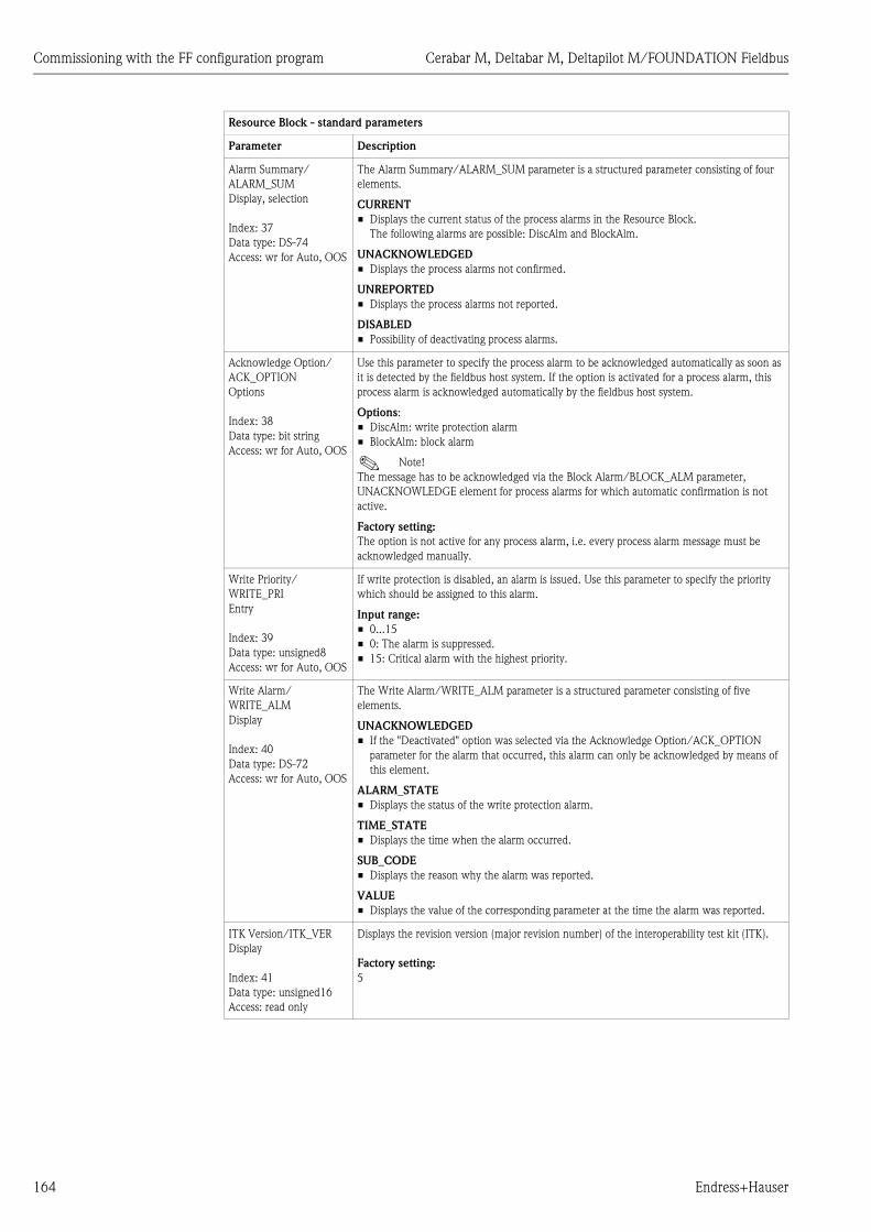
Commissioning with the FF configuration program Cerabar M, Deltabar M, Deltapilot M/FOUNDATION Fieldbus
164 Endress+Hauser
Alarm Summary/
ALARM_SUM
Display, selection
Index: 37
Data type: DS-74
Access: wr for Auto, OOS
The Alarm Summary/ALARM_SUM parameter is a structured parameter consisting of four
elements.
CURRENT
• Displays the current status of the process alarms in the Resource Block.
The following alarms are possible: DiscAlm and BlockAlm.
UNACKNOWLEDGED
• Displays the process alarms not confirmed.
UNREPORTED
• Displays the process alarms not reported.
DISABLED
• Possibility of deactivating process alarms.
Acknowledge Option/
ACK_OPTION
Options
Index: 38
Data type: bit string
Access: wr for Auto, OOS
Use this parameter to specify the process alarm to be acknowledged automatically as soon as
it is detected by the fieldbus host system. If the option is activated for a process alarm, this
process alarm is acknowledged automatically by the fieldbus host system.
Options:
• DiscAlm: write protection alarm
• BlockAlm: block alarm
! Note!
The message has to be acknowledged via the Block Alarm/BLOCK_ALM parameter,
UNACKNOWLEDGE element for process alarms for which automatic confirmation is not
active.
Factory setting:
The option is not active for any process alarm, i.e. every process alarm message must be
acknowledged manually.
Write Priority/
WRITE_PRI
Entry
Index: 39
Data type: unsigned8
Access: wr for Auto, OOS
If write protection is disabled, an alarm is issued. Use this parameter to specify the priority
which should be assigned to this alarm.
Input range:
• 0...15
• 0: The alarm is suppressed.
• 15: Critical alarm with the highest priority.
Write Alarm/
WRITE_ALM
Display
Index: 40
Data type: DS-72
Access: wr for Auto, OOS
The Write Alarm/WRITE_ALM parameter is a structured parameter consisting of five
elements.
UNACKNOWLEDGED
• If the "Deactivated" option was selected via the Acknowledge Option/ACK_OPTION
parameter for the alarm that occurred, this alarm can only be acknowledged by means of
this element.
ALARM_STATE
• Displays the status of the write protection alarm.
TIME_STATE
• Displays the time when the alarm occurred.
SUB_CODE
• Displays the reason why the alarm was reported.
VALUE
• Displays the value of the corresponding parameter at the time the alarm was reported.
ITK Version/ITK_VER
Display
Index: 41
Data type: unsigned16
Access: read only
Displays the revision version (major revision number) of the interoperability test kit (ITK).
Factory setting:
5
Resource Block - standard parameters
Parameter Description

Cerabar M, Deltabar M, Deltapilot M/FOUNDATION Fieldbus Commissioning with the FF configuration program
Endress+Hauser 165
Resource Block - Endress+Hauser parameters
Parameter Description
Device dialog/
DEVICE_DIALOG
Display
Index: 42
Data type: unsigned8
Access: read only
If configuration is unsuitable, this parameter displays a message indicating that a
configuration error is present. The message can indicate which parameter was incorrectly
configured.
Operator code/
S_W_LOCK
Entry
Index: 43
Data type: unsigned16
Access: wr for Auto, OOS
Use this function to enter a code to lock or unlock operation.
Options:
• To lock: Enter a number the release code.
• To unlock: Enter the release code.
! Note!
The release code is "0" in the order configuration. Another release code can be defined in the
Code definition/USER_S_W_UNLOCK parameter. If the user has forgotten the release code,
it can be made visible again by entering the number sequence "5864".
Factory setting:
0
Lockstate/
STATUS_LOCKING
Index: 44
Data type: unsigned8
Access: read only
Displays the current locking status of the device or conditions that can lock the device
(hardware locking, software locking).
DIP switch/
SWITCH_STATUS_LIST
Display
Index: 45
Data type: unsigned8
Access: read only
Displays the status of the active DIP switches.
Electr. serial no./
ELECTRONIC_SERIAL
_NUMBER
Display
Index: 46
Data type: visible string
Access: read only
Displays the serial number of the main electronics (11 alphanumeric characters).
Sci octet str/
SCI_OCTET_STRING
Display
Index: 47
Data type: visible string
Access: wr for Auto, OOS
Internal service parameter.

Commissioning with the FF configuration program Cerabar M, Deltabar M, Deltapilot M/FOUNDATION Fieldbus
166 Endress+Hauser
Download select./
DOWNLOAD_OVERWRI
TE_SELECTION
Options
Index: 48
Data type: unsigned8
Access: wr for Auto, OOS
Selection of data records for the Upload/Download function in Fieldcare.
Prerequisite:
DIP switch 1, 3, 4 and 5 set to "OFF", DIP switch 2 set to "ON" (see picture in Chap. 5.2.1)).
A download with the factory setting "Copy configuration" causes all parameters needed for a
measurement to be downloaded. If the "Copy configuration" setting is changed, it takes effect
only when a corresponding release code is entered into the parameter "Operator code/
S_W_LOCK".
Options:
• Copy configuration: With this option, general configuration parameters are overwritten
except for serial number, order number, calibration, position adjustment, application, and
tag information.
• Device replacement: With this option, general configuration parameters are overwritten
except for serial number, order number, calibration, position adjustment, and PD tag.
• Electronics replacement: With this option, general configuration parameters are
overwritten except for position adjustment.
! Note!
The control strategy is not affected by a download.
Selection of device replacement or electronics replacement takes effect only if a
corresponding release code has been entered beforehand.
Factory setting:
Copy configuration
Code definition/
USER_S_W_UNLOCK
Entry
Index: 49
Data type: unsigned16
Access: wr for Auto, OOS
Use this function to enter a release code with which the device can be unlocked.
User input:
• A number between 0 and 9999
Factory setting:
0
Capability level/
CAPABILITY_LEVEL
Display
Index: 50
Data type: unsigned8
Access: read only
This parameter is integrated into a device to indicate what capability level is supported by the
device.
Description: capability level supported by the device. A value of zero (0) indicates that the
device does not support multiple capability levels.
Factory setting:
1
Compat. level/
COMPATIBILITY_LEVEL
Display
Index: 51
Data type: unsigned8
Access: read only
Indicates up to which specific device version the devices are compatible.
Factory setting:
1
ENP version/
FF_E_N_P_VERSION
Display
Index: 52
Data type: visible string
Access: read only
This parameter indicates the version of the standard for electronic nameplates supported by
the device.
Factory setting:
2.02.00
Pd-tag/FF_PD_TAG
Display
Index: 53
Data type: visible string
Access: read only
The device tag currently configured via the display.
Resource Block - Endress+Hauser parameters
Parameter Description
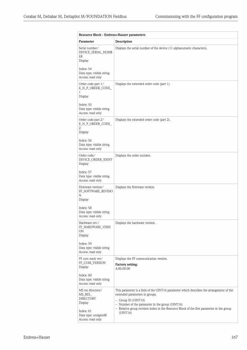
Cerabar M, Deltabar M, Deltapilot M/FOUNDATION Fieldbus Commissioning with the FF configuration program
Endress+Hauser 167
Serial number/
DEVICE_SERIAL_NUMB
ER
Display
Index: 54
Data type: visible string
Access: read only
Displays the serial number of the device (11 alphanumeric characters).
Order code part 1/
E_N_P_ORDER_CODE_
1
Display
Index: 55
Data type: visible string
Access: read only
Displays the extended order code (part 1).
Order code part 2/
E_N_P_ORDER_CODE_
2
Display
Index: 56
Data type: visible string
Access: read only
Displays the extended order code (part 2).
Order code/
DEVICE_ORDER_IDENT
Display
Index: 57
Data type: visible string
Access: read only
Displays the order number.
Firmware version/
FF_SOFTWARE_REVISIO
N
Display
Index: 58
Data type: visible string
Access: read only
Displays the firmware version.
Hardware rev./
FF_HARDWARE_VERSI
ON
Display
Index: 59
Data type: visible string
Access: read only
Displays the hardware version.
FF com stack ver/
FF_COM_VERSION
Display
Index: 60
Data type: visible string
Access: read only
Displays the FF communication version.
Factory setting:
4.00.00.00
MS res directory/
MS_RES_
DIRECTORY
Display
Index: 61
Data type: unsigned8
Access: read only
This parameter is a field of the UINT16 parameter which describes the arrangement of the
extended parameters in groups.
– Group ID (UINT16)
– Number of the parameter in the group (UINT16)
– Relative group revision index in the Resource Block of the first parameter in the group
(UINT16)
Resource Block - Endress+Hauser parameters
Parameter Description

Commissioning with the FF configuration program Cerabar M, Deltabar M, Deltapilot M/FOUNDATION Fieldbus
168 Endress+Hauser
8.12.3 Transducer Blocks
FOUNDATION Fieldbus Transducer Blocks standard parameters
Transducer Block, FOUNDATION Fieldbus standard parameters (all Transducer Blocks)
Parameter Description
Static Revision/ST_REV
Display
Index: 1
Data type: unsigned16
Access: read only
Displays the counter for static parameters of the Transducer Block.
The counter is incremented by one with each change of a static parameter of the
corresponding Transducer Block. The counter counts up to 65535 and then starts again at
zero.
Tag Description/
TAG_DESC
Entry
Index: 2
Data type: octet string
Access: wr for Auto, OOS
Enter a description for the related block or the measuring point e.g. TAG number
(max. 32 alphanumeric characters).
Factory setting:
Empty field
Strategy/STRATEGY
Entry
Index: 3
Data type: unsigned16
Access: wr for Auto, OOS
Enter user-specific value for grouping and thus faster evaluation of the blocks.
Grouping takes place by entering the same numerical value for the Strategy/STRATEGY
parameter of the block in question. These data are neither checked nor processed by the
Transducer Blocks.
Input range:
0...65535
Factory setting:
0
Alert Key/ALERT_KEY
Entry
Index: 4
Data type: unsigned8
Access: wr for Auto, OOS
Enter the identification number for the measuring device or for each individual block.
The control level uses this identification number to sort alarm and event messages and
initiate other processing steps.
Input range:
1...255
Factory setting:
0
Block Mode/MODE_BLK
Selection, display
Index: 5
Data type: DS-69
Access: wr for Auto, OOS
The Block Mode/MODE_BLK parameter is a structured parameter consisting of four
elements. The Transducer Blocks support the "Auto" (automatic) and OOS (out of service)
modes.
TARGET
• Change the block mode.
ACTUAL
• Displays the current block mode.
PERMITTED
• Displays the modes supported by the block.
NORMAL
• Displays the block mode during standard operation.
! Note!
Measured values or information can be forwarded to an Analog Input Block via the Pressure,
Service and DP_Flow Transducer Block. If the Pressure Transducer Block is set to the OOS
block mode, the Primary Value and Secondary Value continue to be updated but the status of
the downstream Analog Input Block changes to BAD.
Block Error/BLOCK_ERR
Display
Index: 6
Data type: bit string
Access: read only
Displays the warning messages and error messages of the software and hardware of the
Transducer Block in question. In addition, this parameter triggers an alarm. If two or more
messages occur simultaneously, the message with the highest priority is shown on the
display.
For the Pressure and Totalizer Block, see possible messages, these Operating Instructions,
Section 10.1 "Messages". The Display and Diagnostic Block do not display any warnings or
error messages.
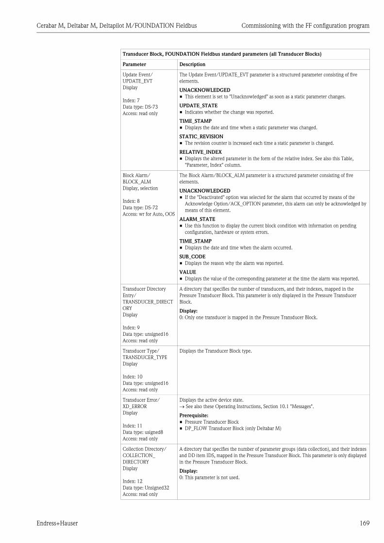
Cerabar M, Deltabar M, Deltapilot M/FOUNDATION Fieldbus Commissioning with the FF configuration program
Endress+Hauser 169
Update Event/
UPDATE_EVT
Display
Index: 7
Data type: DS-73
Access: read only
The Update Event/UPDATE_EVT parameter is a structured parameter consisting of five
elements.
UNACKNOWLEDGED
• This element is set to "Unacknowledged" as soon as a static parameter changes.
UPDATE_STATE
• Indicates whether the change was reported.
TIME_STAMP
• Displays the date and time when a static parameter was changed.
STATIC_REVISION
• The revision counter is increased each time a static parameter is changed.
RELATIVE_INDEX
• Displays the altered parameter in the form of the relative index. See also this Table,
"Parameter, Index" column.
Block Alarm/
BLOCK_ALM
Display, selection
Index: 8
Data type: DS-72
Access: wr for Auto, OOS
The Block Alarm/BLOCK_ALM parameter is a structured parameter consisting of five
elements.
UNACKNOWLEDGED
• If the "Deactivated" option was selected for the alarm that occurred by means of the
Acknowledge Option/ACK_OPTION parameter, this alarm can only be acknowledged by
means of this element.
ALARM_STATE
• Use this function to display the current block condition with information on pending
configuration, hardware or system errors.
TIME_STAMP
• Displays the date and time when the alarm occurred.
SUB_CODE
• Displays the reason why the alarm was reported.
VALUE
• Displays the value of the corresponding parameter at the time the alarm was reported.
Transducer Directory
Entry/
TRANSDUCER_DIRECT
ORY
Display
Index: 9
Data type: unsigned16
Access: read only
A directory that specifies the number of transducers, and their indexes, mapped in the
Pressure Transducer Block. This parameter is only displayed in the Pressure Transducer
Block.
Display:
0: Only one transducer is mapped in the Pressure Transducer Block.
Transducer Type/
TRANSDUCER_TYPE
Display
Index: 10
Data type: unsigned16
Access: read only
Displays the Transducer Block type.
Transducer Error/
XD_ERROR
Display
Index: 11
Data type: usigned8
Access: read only
Displays the active device state.
See also these Operating Instructions, Section 10.1 "Messages".
Prerequisite:
• Pressure Transducer Block
• DP_FLOW Transducer Block (only Deltabar M)
Collection Directory/
COLLECTION_
DIRECTORY
Display
Index: 12
Data type: Unsigned32
Access: read only
A directory that specifies the number of parameter groups (data collection), and their indexes
and DD item IDS, mapped in the Pressure Transducer Block. This parameter is only displayed
in the Pressure Transducer Block.
Display:
0: This parameter is not used.
Transducer Block, FOUNDATION Fieldbus standard parameters (all Transducer Blocks)
Parameter Description
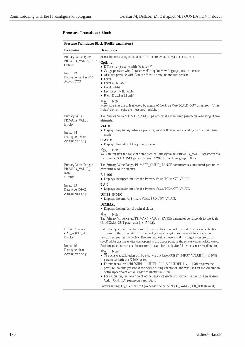
Commissioning with the FF configuration program Cerabar M, Deltabar M, Deltapilot M/FOUNDATION Fieldbus
170 Endress+Hauser
Pressure Transducer Block
Pressure Transducer Block (Profile parameters)
Parameter Description
Primary Value Type/
PRIMARY_VALUE_TYPE
Options
Index: 13
Data type: unsigned16
Access: OOS
Select the measuring mode and the measured variable via this parameter.
Options
• Differential pressure with Deltabar M
• Gauge pressure with Cerabar M/Deltapilot M with gauge pressure sensors
• Absolute pressure with Cerabar M with absolute pressure sensors
• Level
• Level + lin. table
• Level height
• Lev. height + lin. table
• Flow (Deltabar M only)
! Note!
Make sure that the unit selected by means of the Scale Out/SCALE_OUT parameter, "Units
Index" element suits the measured variable.
Primary Value/
PRIMARY_VALUE
Display
Index: 14
Data type: DS-65
Access: read only
The Primary Value/PRIMARY_VALUE parameter is a structured parameter consisting of two
elements.
VALUE
• Displays the primary value - a pressure, level or flow value depending on the measuring
mode.
STATUS
• Displays the status of the primary value.
! Note!
You can transmit the value and status of the Primary Value/PRIMARY_VALUE parameter via
the Channel/CHANNEL parameter ( ä 202) in the Analog Input Block.
Primary Value Range/
PRIMARY_VALUE_
RANGE
Display
Index: 15
Data type: DS-68
Access: read only
The Primary Value Range/PRIMARY_VALUE_ RANGE parameter is a structured parameter
consisting of four elements.
EU_100
• Displays the upper limit for the Primary Value/PRIMARY_VALUE.
EU_0
• Displays the lower limit for the Primary Value/PRIMARY_VALUE.
UNITS_INDEX
• Displays the unit for Primary Value/PRIMARY_VALUE.
DECIMAL
• Displays the number of decimal places.
! Note!
The Primary Value Range/PRIMARY_VALUE_ RANGE parameter corresponds to the Scale
Out/SCALE_OUT parameter ( ä 175).
Hi Trim Sensor/
CAL_POINT_HI
Display
Index: 16
Data type: float
Access: read only
Enter the upper point of the sensor characteristic curve in the event of sensor recalibration.
By means of this parameter, you can assign a new target pressure value to a reference
pressure present at the device. The pressure value present and the target pressure value
specified for this parameter correspond to the upper point in the sensor characteristic curve.
Position adjustment has to be performed again for the device following sensor recalibration.
! Note!
• The sensor recalibration can be reset via the Reset/RESET_INPUT_VALUE ( ä 198)
parameter with the "2509" code.
• Hi trim measured/PRESSURE_1_UPPER_CAL_MEASURED ( ä 176) displays the
pressure that was present at the device during calibration and was used for the calibration
of the upper point of the sensor characteristic curve.
• For calibrating the lower point of the sensor characteristic curve, see the Lo trim sensor/
CAL_POINT_LO parameter description.
Factory setting: High sensor limit (Sensor range/SENSOR_RANGE, EU_100 element)

Cerabar M, Deltabar M, Deltapilot M/FOUNDATION Fieldbus Commissioning with the FF configuration program
Endress+Hauser 171
Lo trim sensor/
CAL_POINT_LO
Display
Index: 17
Data type: float
Access: read only
Enter the lower point of the sensor characteristic curve in the event of sensor recalibration.
By means of this parameter, you can assign a new target pressure value to a reference
pressure present at the device. The pressure value present and the target pressure value
specified for this parameter correspond to the lower point in the sensor characteristic curve.
Position adjustment has to be performed again for the device following sensor recalibration.
! Note!
• The sensor recalibration can be reset via the Reset/RESET_INPUT_VALUE ( ä 170)
parameter with the "2509" code.
• The Lo trim measured/PRESSURE_1_LOWER_CAL_MEASURED ( ä 176) parameter
displays the pressure that was present at the device during calibration and was used for the
calibration of the lower point of the sensor characteristic curve.
• For calibrating the upper point of the sensor characteristic curve, see Hi Trim Sensor/
CAL_POINT_HI parameter description.
Factory setting: Low sensor limit (Sensor range/SENSOR_RANGE, Element EU_0)
Cal min span/
CAL_MIN_
SPAN
Display
Index: 18
Data type: float
Access: read only
Displays the smallest possible span.
Press. eng. unit/
CAL_UNIT
Entry
Index: 19
Data type: unsigned16
Access: OOS
Select the pressure unit.
If a new pressure unit is selected, all pressure-specific parameters are converted and displayed
with the new unit.
Options
• mbar, bar
• mmH2O, mH2O, inH2O, ftH2O
• Pa, kPa, MPa
• psi
• mmHg, inHg
• kgf/cm2
Factory setting:
mbar or bar depending on the sensor nominal measuring range, or as per order specifications
Pressure Transducer Block (Profile parameters)
Parameter Description
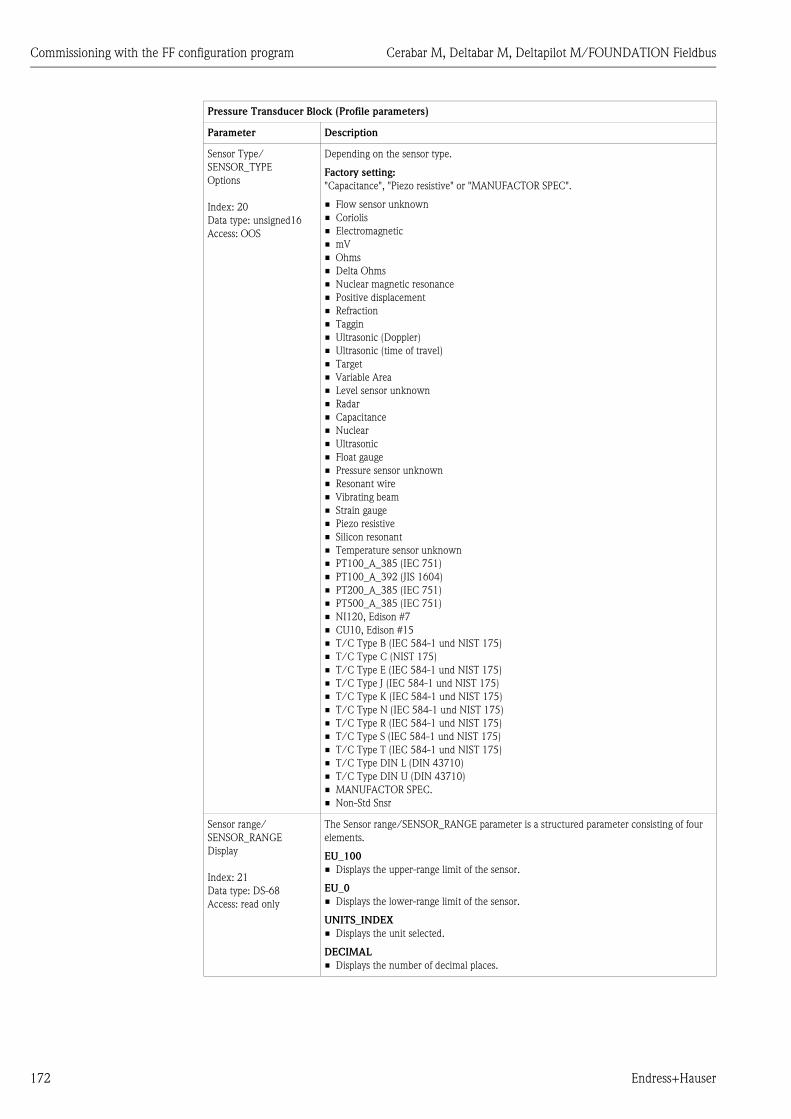
Commissioning with the FF configuration program Cerabar M, Deltabar M, Deltapilot M/FOUNDATION Fieldbus
172 Endress+Hauser
Sensor Type/
SENSOR_TYPE
Options
Index: 20
Data type: unsigned16
Access: OOS
Depending on the sensor type.
Factory setting:
"Capacitance", "Piezo resistive" or "MANUFACTOR SPEC".
• Flow sensor unknown
• Coriolis
• Electromagnetic
• mV
• Ohms
• Delta Ohms
• Nuclear magnetic resonance
• Positive displacement
• Refraction
• Taggin
• Ultrasonic (Doppler)
• Ultrasonic (time of travel)
• Target
• Variable Area
• Level sensor unknown
• Radar
• Capacitance
• Nuclear
• Ultrasonic
• Float gauge
• Pressure sensor unknown
• Resonant wire
• Vibrating beam
• Strain gauge
• Piezo resistive
• Silicon resonant
• Temperature sensor unknown
• PT100_A_385 (IEC 751)
• PT100_A_392 (JIS 1604)
• PT200_A_385 (IEC 751)
• PT500_A_385 (IEC 751)
• NI120, Edison #7
• CU10, Edison #15
• T/C Type B (IEC 584-1 und NIST 175)
• T/C Type C (NIST 175)
• T/C Type E (IEC 584-1 und NIST 175)
• T/C Type J (IEC 584-1 und NIST 175)
• T/C Type K (IEC 584-1 und NIST 175)
• T/C Type N (IEC 584-1 und NIST 175)
• T/C Type R (IEC 584-1 und NIST 175)
• T/C Type S (IEC 584-1 und NIST 175)
• T/C Type T (IEC 584-1 und NIST 175)
• T/C Type DIN L (DIN 43710)
• T/C Type DIN U (DIN 43710)
• MANUFACTOR SPEC.
• Non-Std Snsr
Sensor range/
SENSOR_RANGE
Display
Index: 21
Data type: DS-68
Access: read only
The Sensor range/SENSOR_RANGE parameter is a structured parameter consisting of four
elements.
EU_100
• Displays the upper-range limit of the sensor.
EU_0
• Displays the lower-range limit of the sensor.
UNITS_INDEX
• Displays the unit selected.
DECIMAL
• Displays the number of decimal places.
Pressure Transducer Block (Profile parameters)
Parameter Description
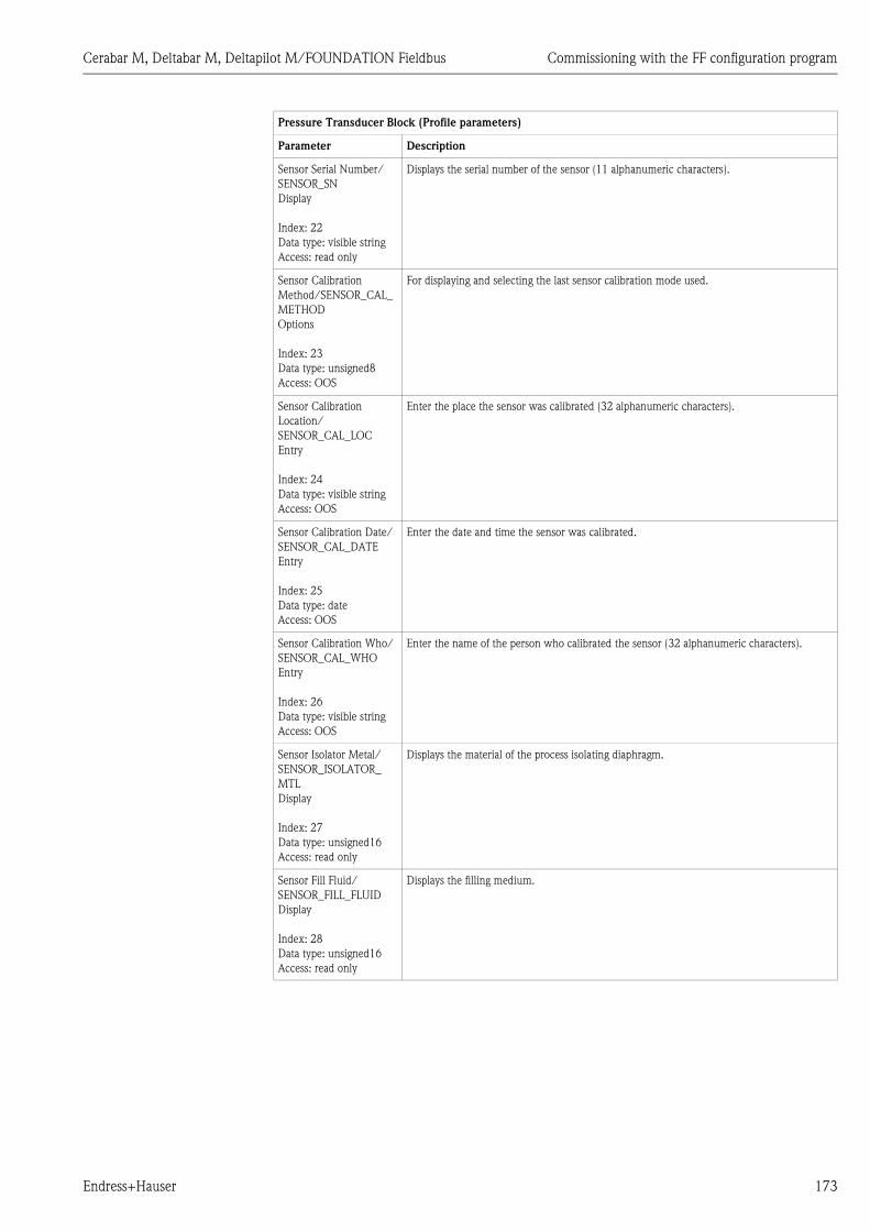
Cerabar M, Deltabar M, Deltapilot M/FOUNDATION Fieldbus Commissioning with the FF configuration program
Endress+Hauser 173
Sensor Serial Number/
SENSOR_SN
Display
Index: 22
Data type: visible string
Access: read only
Displays the serial number of the sensor (11 alphanumeric characters).
Sensor Calibration
Method/SENSOR_CAL_
METHOD
Options
Index: 23
Data type: unsigned8
Access: OOS
For displaying and selecting the last sensor calibration mode used.
Sensor Calibration
Location/
SENSOR_CAL_LOC
Entry
Index: 24
Data type: visible string
Access: OOS
Enter the place the sensor was calibrated (32 alphanumeric characters).
Sensor Calibration Date/
SENSOR_CAL_DATE
Entry
Index: 25
Data type: date
Access: OOS
Enter the date and time the sensor was calibrated.
Sensor Calibration Who/
SENSOR_CAL_WHO
Entry
Index: 26
Data type: visible string
Access: OOS
Enter the name of the person who calibrated the sensor (32 alphanumeric characters).
Sensor Isolator Metal/
SENSOR_ISOLATOR_
MTL
Display
Index: 27
Data type: unsigned16
Access: read only
Displays the material of the process isolating diaphragm.
Sensor Fill Fluid/
SENSOR_FILL_FLUID
Display
Index: 28
Data type: unsigned16
Access: read only
Displays the filling medium.
Pressure Transducer Block (Profile parameters)
Parameter Description

Commissioning with the FF configuration program Cerabar M, Deltabar M, Deltapilot M/FOUNDATION Fieldbus
174 Endress+Hauser
Secondary Value/
SECONDARY_VALUE
Display
Index: 29
Data type: DS-65
Access: read only
The Secondary Value/SECONDARY_VALUE parameter is a structured parameter consisting
of two elements.
VALUE
• Displays the second process value, here the sensor temperature.
STATUS
• Displays the status of the second process value.
! Note!
You can transmit the value and status of the Secondary Value/SECONDARY_VALUE
parameter via the Channel/CHANNEL parameter ( ä 202) in the Analog Input Block.
The Channel/CHANNEL parameter must be set to "2" (Cerabar/Deltapilot) or "4" (Deltabar)
for this purpose.
Secondary Value Unit/
SECONDARY_VALUE_
UNIT
Options
Index: 30
Data type: unsigned16
Access: wr for Auto, OOS
Select the unit for the second process value.
See also the Secondary Value/SECONDARY_VALUE parameter description.
Pressure Transducer Block (Endress+Hauser parameters)
Parameter Description
Device dialog/
DEVICE_DIALOG
Display
Index: 31
Data type: unsigned8
Access: read only
If configuration is unsuitable, this parameter displays a message indicating that a
configuration error is present. The message can indicate which parameter was incorrectly
configured.
Operator code/
S_W_LOCK
Entry
Index: 32
Data type: unsigned16
Access: wr for Auto, OOS
Use this function to enter a code to lock or unlock operation.
Options:
• To lock: Enter a number the release code.
• To unlock: Enter the release code.
! Note!
The release code is "0" in the order configuration. Another release code can be defined in the
Code definition/USER_S_W_UNLOCK parameter. If the user has forgotten the release code,
it can be made visible again by entering the number sequence "5864".
Factory setting:
0
Lockstate/
STATUS_LOCKING
Display
Index: 33
Data type: unsigned8
Access: read only
Displays the current locking status of the device or conditions that can lock the device
(hardware locking, software locking).
DIP switch/
SWITCH_STATUS_LIST
Display
Index: 34
Data type: unsigned8
Access: read only
Displays the DIP switches activated on the electronic insert.
• P1/P2 switch (Deltabar, inputs inversion enabled)
• Lin/sq. switch (Deltabar, flow has been enabled)
• Simulation switch (AI simulation enabled)
• Damping switch (damping enabled)
• HW lock. switch (HW locking enabled)
Pressure Transducer Block (Profile parameters)
Parameter Description

Cerabar M, Deltabar M, Deltapilot M/FOUNDATION Fieldbus Commissioning with the FF configuration program
Endress+Hauser 175
Scale In/SCALE_IN
Entry
Index: 35
Data type: DS-65
Access: OOS
The Scale In/SCALE_IN-parameter is a structured parameter consisting of four elements.
EU_100
• "Pressure" measuring mode; "Level in pressure" measuring mode; "Level in height"
measuring mode; enter the upper limit for the pressure value of the Transducer Block.
• "Flow" measuring mode: Enter the maximum pressure of the primary device.
See layout sheet of primary element. This value is assigned to the maximum flow value
(See the following Scale Out/SCALE_OUT parameter, EU_100 element).
• Factory setting: Upper range limit of the sensor
EU_0
• "Pressure" measuring mode; "Level in pressure" measuring mode; "Level in height"
measuring mode; "Flow" measuring mode: Enter the lower limit for the pressure value of
the Transducer Block.
• Factory setting: 0
UNITS_INDEX
• Select the unit for input scaling.
DECIMAL
• Displays the number of decimal places.
Scale Out/SCALE_OUT
Entry
Index: 36
Data type: DS-68
Access: OOS
The Scale Out/SCALE_OUT-parameter is a structured parameter consisting of four elements.
EU_100
• "Pressure" measuring mode; "Level in pressure" measuring mode; "Level in height"
measuring mode; enter the upper limit for the output value of the Transducer Block.
Factory setting: 100
• "Flow" measuring mode: Enter the maximum flow of the primary device.
See also layout sheet of primary element. The maximum flow is assigned to the maximum
pressure which you enter via the Scale In/SCALE_IN parameter, EU_100 element.
Factory setting: 1.0
EU_0
• "Pressure" measuring mode; "Level in pressure" measuring mode; "Level in height"
measuring mode; enter the lower limit for the output value of the Transducer Block.
• Factory setting: 0
UNITS_INDEX
• Select the unit for output scaling.
DECIMAL
• Displays the number of decimal places.
! Note!
Make sure that the unit selected by means of the Scale Out/SCALE_OUT parameter, "Units
Index" element suits the measured variable.
See also the Primary Value Type/PRIMARY_VALUE_TYPE ( ä 170) parameter
descriptions.
Damping/
PRESSURE_1_DAMPING
Entry
Index: 37
Data type: float
Access: OOS
Enter damping time (time constant ).The damping affects the speed at which all subsequent elements, such as the local operation,
measured value (Primary Value) and output value of the Analog Input Block react to a change
in the pressure. For this purpose, switch the damping switch "On".
Input range:
0.0 to 999.0 s
Factory setting:
2.0 s or as per order specifications
Pressure Transducer Block (Endress+Hauser parameters)
Parameter Description
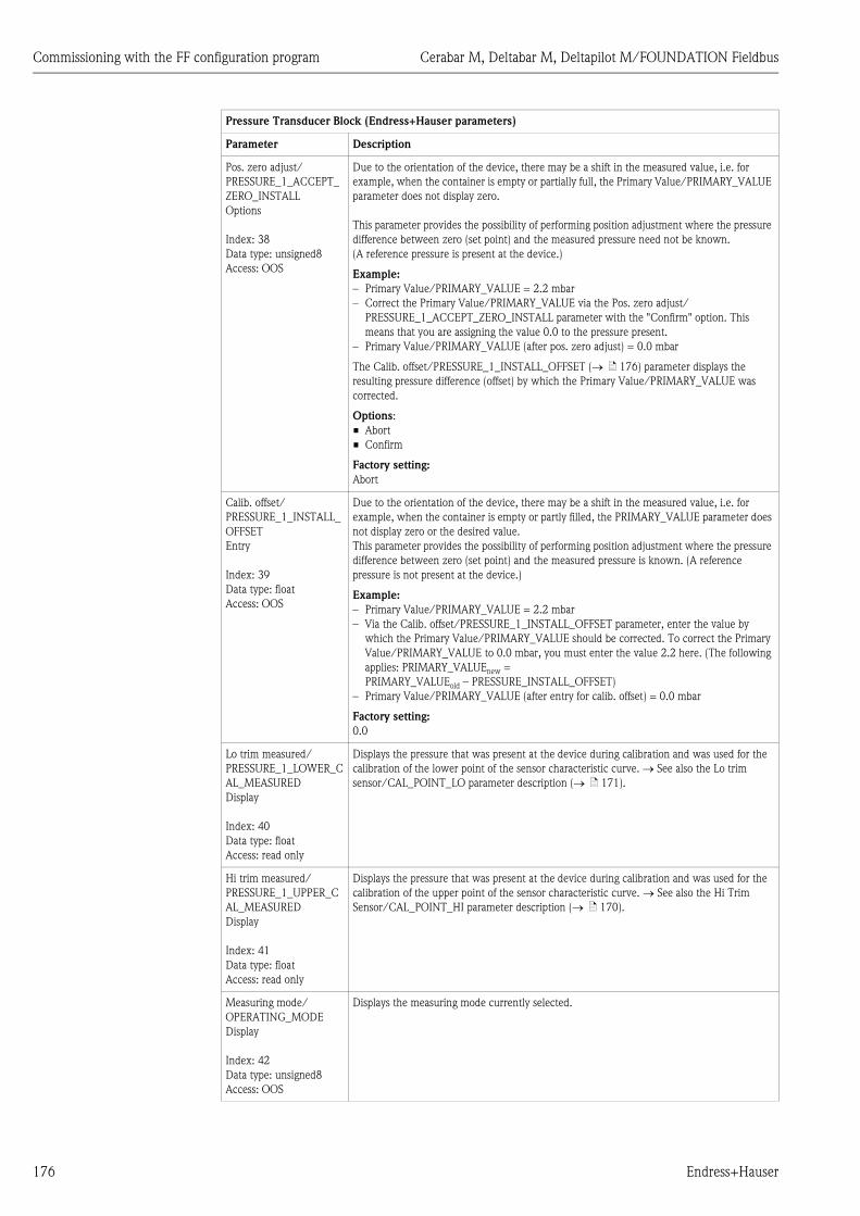
Commissioning with the FF configuration program Cerabar M, Deltabar M, Deltapilot M/FOUNDATION Fieldbus
176 Endress+Hauser
Pos. zero adjust/
PRESSURE_1_ACCEPT_
ZERO_INSTALL
Options
Index: 38
Data type: unsigned8
Access: OOS
Due to the orientation of the device, there may be a shift in the measured value, i.e. for
example, when the container is empty or partially full, the Primary Value/PRIMARY_VALUE
parameter does not display zero.
This parameter provides the possibility of performing position adjustment where the pressure
difference between zero (set point) and the measured pressure need not be known.
(A reference pressure is present at the device.)
Example:
– Primary Value/PRIMARY_VALUE = 2.2 mbar
– Correct the Primary Value/PRIMARY_VALUE via the Pos. zero adjust/
PRESSURE_1_ACCEPT_ZERO_INSTALL parameter with the "Confirm" option. This
means that you are assigning the value 0.0 to the pressure present.
– Primary Value/PRIMARY_VALUE (after pos. zero adjust) = 0.0 mbar
The Calib. offset/PRESSURE_1_INSTALL_OFFSET ( ä 176) parameter displays the
resulting pressure difference (offset) by which the Primary Value/PRIMARY_VALUE was
corrected.
Options:
• Abort
• Confirm
Factory setting:
Abort
Calib. offset/
PRESSURE_1_INSTALL_
OFFSET
Entry
Index: 39
Data type: float
Access: OOS
Due to the orientation of the device, there may be a shift in the measured value, i.e. for
example, when the container is empty or partly filled, the PRIMARY_VALUE parameter does
not display zero or the desired value.
This parameter provides the possibility of performing position adjustment where the pressure
difference between zero (set point) and the measured pressure is known. (A reference
pressure is not present at the device.)
Example:
– Primary Value/PRIMARY_VALUE = 2.2 mbar
– Via the Calib. offset/PRESSURE_1_INSTALL_OFFSET parameter, enter the value by
which the Primary Value/PRIMARY_VALUE should be corrected. To correct the Primary
Value/PRIMARY_VALUE to 0.0 mbar, you must enter the value 2.2 here. (The following
applies: PRIMARY_VALUEnew =
PRIMARY_VALUEold – PRESSURE_INSTALL_OFFSET)
– Primary Value/PRIMARY_VALUE (after entry for calib. offset) = 0.0 mbar
Factory setting:
0.0
Lo trim measured/
PRESSURE_1_LOWER_C
AL_MEASURED
Display
Index: 40
Data type: float
Access: read only
Displays the pressure that was present at the device during calibration and was used for the
calibration of the lower point of the sensor characteristic curve. See also the Lo trim
sensor/CAL_POINT_LO parameter description ( ä 171).
Hi trim measured/
PRESSURE_1_UPPER_C
AL_MEASURED
Display
Index: 41
Data type: float
Access: read only
Displays the pressure that was present at the device during calibration and was used for the
calibration of the upper point of the sensor characteristic curve. See also the Hi Trim
Sensor/CAL_POINT_HI parameter description ( ä 170).
Measuring mode/
OPERATING_MODE
Display
Index: 42
Data type: unsigned8
Access: OOS
Displays the measuring mode currently selected.
Pressure Transducer Block (Endress+Hauser parameters)
Parameter Description

Cerabar M, Deltabar M, Deltapilot M/FOUNDATION Fieldbus Commissioning with the FF configuration program
Endress+Hauser 177
Level selection/
LEVEL_ADJUSTMENT
Display, selection
Index: 43
Data type: unsigned8
Access: OOS
Select the method for calculating the level
Options:
• In pressure
If this option is selected, specify two pressure/level value pairs. The level value is displayed
directly in the unit that you select via the Unit before Lin./OUT_UNIT_EASY parameter.
• In height
If this option is selected, specify two height/level value pairs. From the measured pressure,
the device first calculates the height using the density. This information is then used to
calculate the level in the Unit before Lin./OUT_UNIT_EASY selected using the two value
pairs specified.
Factory setting:
In pressure
Corrected press./
PRESSURE_1_AFTER_C
ALIBRATION
Display
Index: 44
Data type: float
Access: read only
Displays the measured pressure after sensor trim and position adjustment.
! Note!
If this value is not equal to "0", it can be corrected to "0" by the position adjustment.
Meas. pressure/
PRESSURE_1_FINAL_VA
LUE
Display
Index: 45
Data type: float
Access: read only
Displays the measured pressure after sensor trim, position adjustment and damping.
Cerabar M and Deltapilot M:
P01-xxxxxxxx-05-xx-xx-en-009
Deltabar M:
P01-xxxxxxxx-05-xx-xx-en-010
Pressure Transducer Block (Endress+Hauser parameters)
Parameter Description
P PVAnalogInputBlock
Sensor
Pressure
Level
Pressure af. damp
Damping
Corrected Press.
Positionadjust-ment
Sensortrim
Sensor pressure
Simulation valuePressure
Measuring pressure
Electr.Delta P
PV = Primary Value
P PV
Transducer Block
Sensor
Pressure
LevelDampingPositionadjust-ment
Sensortrim
Flow
AnalogInputBlock
Pressure af. damp
Corrected Press.
Sensor pressure
Measuring pressure
PV = Primary Value

Commissioning with the FF configuration program Cerabar M, Deltabar M, Deltapilot M/FOUNDATION Fieldbus
178 Endress+Hauser
Lin. mode/
LINEARIZATION_
TABLE_MODE
Entry
Index: 46
Data type: unsigned8
Access: OOS
Select the linearization mode.
Options:
• Linear
The level is output without being converted beforehand. Level before lin/
MEASURED_LEVEL_AFTER_SIMULATION is output.
• Erase table
The existing linearization table is deleted.
• Manual entry (sets the table to the edit mode, an alarm is output):
The value pairs of the table (X-value:/TB_LINEARIZATION_ TABLE_X_VALUE and Y-
value:/TB_LINEARIZATION_ TABLE_Y_VALUE) are entered manually.
• Semiautomatic entry (sets the table to the edit mode, an alarm is output):
The container is emptied or filled in stages in this entry mode. The device automatically
records the level value (X-value:/TB_LINEARIZATION_ TABLE_X_VALUE). The
associated volume, mass or %-value is entered manually (X-value:/TB_LINEARIZATION_
TABLE_X_VALUE).
• Activate table
The table entered is activated and checked with this option. The device shows the level
after linearization.
Factory setting:
Manual
Unit after lin./
AFTER_LINEARIZATION
_UNIT
Display, selection
Index: 47
Data type: unsigned16
Access: OOS
Select the linearization unit (unit of the Y-value).
Options:
• %
• cm, dm, m, mm
• hl
• in3, ft3, m3
• l
• in, ft
• kg, t
• lb
• gal
• Igal
Factory setting:
%
Line numb./
LINEARIZATION_
TABLE_INDEX
Entry
Index: 48
Data type: unsigned8
Access: wr for Auto, OOS
Enter the number of the current point in the table.
The subsequent entries in X-value:/TB_LINEARIZATION_ TABLE_X_VALUE and
Y-value:/TB_LINEARIZATION_ TABLE_Y_VALUE refer to this point.
Input range:
• 1 ... 32
X-value:/
TB_LINEARIZATION_
TABLE_X_VALUE
Display
Index: 49
Data type: float
Access: read only
Display the X-value (level before linearization) for the specific point in the table and confirm.
Note:
If "Lin. mode" = "Manual", the level value is displayed.
If "Lin. mode" = "Semiautomatic", the level value is displayed and has to be confirmed by
entering the Y-value that cannot be edited.
Prerequisite:
• Lin. mode/LINEARIZATION_ TABLE_MODE = Manual entry.
Y-value:/
TB_LINEARIZATION_
TABLE_Y_VALUE
Entry
Index: 50
Data type: float
Access: OOS
Enter the Y-value (value after linearization) for the specific point in the table in the
"Semiautomatic" mode.
Note:
If "Lin. mode" = "Manual", the system displays the points after linearization.
If "Lin. mode" = "Semiautomatic", entry of the points after linearization.
The linearization table must be monotonic increasing or decreasing.
Pressure Transducer Block (Endress+Hauser parameters)
Parameter Description

Cerabar M, Deltabar M, Deltapilot M/FOUNDATION Fieldbus Commissioning with the FF configuration program
Endress+Hauser 179
Edit table/
LINEARIZATION_TABLE
_EDIT
Display, selection
Index: 51
Data type: unsigned8
Access: OOS
Select the function for entering the table.
Options:
• Next point: enter the next point.
• Current point: stay on the current point to correct a mistake for example.
• Previous point: skip back to the previous point to correct a mistake for example.
• Insert point: insert an additional point (see example below).
• Delete point: delete the current point (see example below).
Example: Add a point - in this case between the 4th and 5th point for example
– Select point 5 via the "Line-numb." parameter.
– Select the "Insert point" option via the "Edit table" parameter.
– Point 5 is displayed for the "Line-numb" parameter. Enter new values for the "X-value" and
"Y-value" parameters.
Example: Delete a point - in this case the 5th point for example.
– Select point 5 via the "Line-numb." parameter.
– Select the "Delete point" option via the "Edit table" parameter.
– The 5th point is deleted. All of the subsequent points are moved up one number
i.e. following deletion, the 6th point becomes Point 5.
Factory setting:
Current point
Tank Description/
LEVEL_TANK_
DESCRIPTION
Entry
Index: 52
Data type: visible string
Access: wr for Auto, OOS
Enter tank description. (max. 32 alphanumeric characters)
Factory setting:
_ _ _ _ _ _ _ _ _ _ _ _ _ _ _ _ _ _ _ _ _ _ _ _ _ _ _ _ _ _ _ _
Tank content/
MEASURED_TANK_CO
NTENT_AFTER_SIM
Display
Index: 53
Data type: float
Access: read only
Displays the level value after linearization.
Sensor pressure/
PRESSURE_1_AFTER_SE
NSOR
Display
Index: 54
Data type: float
Access: read only
Displays the measured pressure before sensor trim, position adjustment and damping.
See also the following graphic, Meas. pressure/PRESSURE_1_FINAL_VALUE parameter
description.
Pressure Transducer Block (Endress+Hauser parameters)
Parameter Description

Commissioning with the FF configuration program Cerabar M, Deltabar M, Deltapilot M/FOUNDATION Fieldbus
180 Endress+Hauser
Pressure af. damp./
PRESSURE_1_AFTER_D
AMPING
Display
Index: 55
Data type: float
Access: read only
Displays the measured pressure after sensor trim, position adjustment and damping. This
value corresponds to the Primary Value/PRIMARY_VALUE parameter in the "Pressure"
measuring mode.
Cerabar M and Deltapilot M:
P01-xxxxxxxx-05-xx-xx-en-009
Deltabar M:
P01-xxxxxxxx-05-xx-xx-en-010
Level before lin/
MEASURED_LEVEL_AF
TER_SIMULATION
Display
Index: 56
Data type: float
Access: read only
Displays the level value prior to linearization.
Lin tab index 01/
LIN_TAB_X_Y_VALUE_
1
Entry/Display
Index: 57
Data type: record
Access: OOS
Position 1 of the X and Y values of the linearization table.
The X and Y values can be entered (edited) if the Lin. mode/LINEARIZATION_
TABLE_MODE is set to "Manual". The data can only be displayed if the Lin. mode/
LINEARIZATION_ TABLE_MODE is not set to "Manual".
...
...
...
Pressure Transducer Block (Endress+Hauser parameters)
Parameter Description
P PVAnalogInputBlock
Sensor
Pressure
Level
Pressure af. damp
Damping
Corrected Press.
Positionadjust-ment
Sensortrim
Sensor pressure
Simulation valuePressure
Measuring pressure
Electr.Delta P
PV = Primary Value
P PV
Transducer Block
Sensor
Pressure
LevelDampingPositionadjust-ment
Sensortrim
Flow
AnalogInputBlock
Pressure af. damp
Corrected Press.
Sensor pressure
Measuring pressure
PV = Primary Value

Cerabar M, Deltabar M, Deltapilot M/FOUNDATION Fieldbus Commissioning with the FF configuration program
Endress+Hauser 181
Lin tab index 32/
LIN_TAB_X_Y_VALUE_
32
Entry/Display
Index: 88
Data type: record
Access: OOS
Position 32 of the X and Y values of the linearization table.
The X and Y values can be entered (edited) if the Lin. mode/LINEARIZATION_
TABLE_MODE is set to "Manual". The data can only be displayed if the Lin. mode/
LINEARIZATION_ TABLE_MODE is not set to "Manual".
Sensor meas. type/
SENSOR_MEASUREME
NT_TYPE
Display
Index: 89
Data type: unsigned16
Access: read only
Displays the sensor type.
• Deltabar M = differential
• Cerabar M with gauge pressure sensors = gauge
• Cerabar M with absolute pressure sensors = absolute
• Deltapilot M with gauge pressure sensors = gauge
Height unit/
HEIGHT_UNIT_EASY
Options
Index: 90
Data type: unsigned16
Access: OOS
Select the height unit. The measured pressure is converted to the selected height unit using
the Density unit/DENSITY_UNIT_EASY and Adjust density/
LEVEL_ADJUST_DENSITY_EASY parameter.
Prerequisite:
Primary Value Type/PRIMARY_VALUE_TYPE parameter is set to"Level height" or
"Lev. height+LinTab".
Options:
• mm
• m
• in
• ft
Factory setting:
m
Unit before Lin./
OUT_UNIT_EASY
Options
Index: 91
Data type: unsigned16
Access: OOS
Select the unit for the measured value display for the level before linearization.
! Note!
The unit selected is only used to describe the measured value. This means that the measured
value is not converted when a new output unit is selected.
Example:
• Current measured value: 0.3 ft
• New output unit: m
• New measured value: 0.3 m
Options
• %
• mm, cm, dm, m
• ft, in
• m3, in3
• l, hl
• ft3
• gal, Igal
• kg, t
• lb
Factory setting:
%
Pressure Transducer Block (Endress+Hauser parameters)
Parameter Description

Commissioning with the FF configuration program Cerabar M, Deltabar M, Deltapilot M/FOUNDATION Fieldbus
182 Endress+Hauser
Calibration mode/
LEVEL_ADJUST_MODE
_EASY
Options
Index: 92
Data type: unsigned8
Access: OOS
Select the calibration mode.
Options:
• Wet
Wet calibration takes place by filling and emptying the container. In the case of two
different levels, the level, volume, mass or percentage value entered is assigned to the
pressure measured at this point in time. ( See also this table, Empty calibration/
LOW_LEVEL_EASY and Full calib./HIGH_LEVEL_EASY parameter descriptions)
• Dry
Dry calibration is a theoretical calibration. For this calibration, you specify two pressure/
level value pairs via the following parameters Empty calibration/LOW_LEVEL_EASY,
Empty pressure/LOW_LEVEL_PRESSURE_EASY, Full calib./HIGH_LEVEL_EASY and
Full pressure/HIGH_LEVEL_PRESSURE_EASY.
Factory setting:
Wet - if PRIMARY_VALUE_TYPE "Level" or "Level+LinTab"
Dry - if PRIMARY_VALUE_TYPE "Level height" or "Lev height+LinTab"
Density unit/
DENSITY_UNIT_EASY
Display
Index: 93
Data type: unsigned16
Access: read only
Displays the density unit. The measured pressure is converted to a height using the Height
unit/HEIGHT_UNIT_EASY and Adjust density/LEVEL_ADJUST_DENSITY_EASY
parameters.
Factory setting:
• g/cm3
Adjust density/
LEVEL_ADJUST_DENSIT
Y_EASY
Index: 94
Data type: FLOAT
Access: OOS
Enter the density of the medium. The measured pressure is converted to a height using the
Height unit/HEIGHT_UNIT_EASY, Density unit/DENSITY_UNIT_EASY and Adjust
density/LEVEL_ADJUST_DENSITY_EASY parameters.
Factory setting:
1.0
Empty height/
LEVEL_OFFSET_EASY
Entry/Display
Index: 95
Data type: FLOAT
Access: OOS
Enter the level, volume, mass or percentage value for the lower calibration point (empty
container).
The values entered for the Empty calibration/LOW_LEVEL_EASY and Empty pressure/
LOW_LEVEL_PRESSURE_EASY parameters form the pressure/level value pair for the lower
calibration point. The unit is selected via the Unit before Lin./OUT_UNIT_EASY parameter
(➞ Seite 181).
Prerequisite:
• Level selection/LEVEL_ADJUSTMENT = in height or Primary Value/PRIMARY_VALUE
parameter is set to "Level height" or "Lev height+LinTab"
• Calibration mode/LEVEL_ADJUST_MODE_EASY = Dry
Factory setting:
0.0
Full height/
LEVEL_100_PERCENT_
EASY
Entry/Display
Index: 96
Data type: FLOAT
Access: OOS
Enter the height, volume, mass or percentage value for the upper calibration point (container
full).
The values entered for the Full calib./HIGH_LEVEL_EASY and Full pressure/
HIGH_LEVEL_PRESSURE_EASY parameters form the pressure/level value pair for the upper
calibration point The unit is selected via the Unit before Lin./OUT_UNIT_EASY parameter
( ä 181).
Prerequisite:
• Level selection/LEVEL_ADJUSTMENT = in height or Primary Value/PRIMARY_VALUE
parameter is set to "Level height" or "Lev height+LinTab"
• Calibration mode/LEVEL_ADJUST_MODE_EASY = Dry
Factory setting:
100.0
Pressure Transducer Block (Endress+Hauser parameters)
Parameter Description
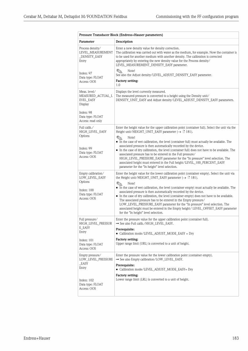
Cerabar M, Deltabar M, Deltapilot M/FOUNDATION Fieldbus Commissioning with the FF configuration program
Endress+Hauser 183
Process density/
LEVEL_MEASUREMENT
_DENSITY_EASY
Entry
Index: 97
Data type: FLOAT
Access: OOS
Enter a new density value for density correction.
The calibration was carried out with water as the medium, for example. Now the container is
to be used for another medium with another density. The calibration is corrected
appropriately by entering the new density value for the Process density/
LEVEL_MEASUREMENT_DENSITY_EASY parameter.
! Note!
See also the Adjust density/LEVEL_ADJUST_DENSITY_EASY parameter.
Factory setting:
1.0
Meas. level/
MEASURED_ACTUAL_L
EVEL_EASY
Display
Index: 98
Data type: FLOAT
Access: read only
Displays the level currently measured.
The measured pressure is converted to a height using the Density unit/
DENSITY_UNIT_EASY and Adjust density/LEVEL_ADJUST_DENSITY_EASY parameters.
Full calib./
HIGH_LEVEL_EASY
Options
Index: 99
Data type: FLOAT
Access: OOS
Enter the height value for the upper calibration point (container full). Select the unit via the
Height unit/HEIGHT_UNIT_EASY parameter ( ä 181).
! Note!
• In the case of wet calibration, the level (container full) must actually be available. The
associated pressure is then automatically recorded by the device.
• In the case of dry calibration, the level (container full) does not have to be available. The
associated pressure has to be entered in the Full pressure/
HIGH_LEVEL_PRESSURE_EASY parameter for the "In pressure" level selection. The
associated height must entered in the Full height/LEVEL_100_PERCENT_EASY
parameter for the "In height" level selection.
Empty calibration/
LOW_LEVEL_EASY
Options
Index: 100
Data type: FLOAT
Access: OOS
Enter the height value for the lower calibration point (container empty). Select the unit via
the Height unit/HEIGHT_UNIT_EASY parameter ( ä 181).
! Note!
• In the case of wet calibration, the level (container empty) must actually be available. The
associated pressure is then automatically recorded by the device.
• In the case of dry calibration, the level (container empty) does not have to be available.
The associated pressure has to be entered in the Empty pressure/
LOW_LEVEL_PRESSURE_EASY parameter for the "In pressure" level selection. The
associated height must be entered in the Empty height/ LEVEL_OFFSET_EASY parameter
for the "In height" level selection.
Full pressure/
HIGH_LEVEL_PRESSUR
E_EASY
Entry
Index: 101
Data type: FLOAT
Access: OOS
Enter the pressure value for the upper calibration point (container full).
➞ See also Full calib./HIGH_LEVEL_EASY.
Prerequisite:
• Calibration mode/LEVEL_ADJUST_MODE_EASY = Dry
Factory setting:
Upper range limit (URL) is converted to a unit of height.
Empty pressure/
LOW_LEVEL_PRESSURE
_EASY
Entry
Index: 102
Data type: FLOAT
Access: OOS
Enter the pressure value for the lower calibration point (container empty).
➞ See also Empty calibration/LOW_LEVEL_EASY.
Prerequisite:
• Calibration mode/LEVEL_ADJUST_MODE_EASY= Dry
Factory setting:
Lower range limit (LRL) is converted to a unit of height.
Pressure Transducer Block (Endress+Hauser parameters)
Parameter Description

Commissioning with the FF configuration program Cerabar M, Deltabar M, Deltapilot M/FOUNDATION Fieldbus
184 Endress+Hauser
Electr. delta P/
ELECTRIC_DELTA_P_C
ONTROL
Options
Index: 103
Data type: unsigned8
Access: OOS
For switching the electr. delta P application on or off with an external or constant value.
Options:
• Off
• External value
• Constant
Factory setting:
Off
E.delta p selec./
E_DELTA_P_INPUT_SEL
ECTOR
Options
Index: 104
Data type: unsigned8
Access: OOS
Select the input of the Input Selector Block which should be used for the electr. delta P
application.
Options:
• Input 1
• Input 2
• Input 3
• Input 4
Factory setting:
Input 1
E. delta p value/
E_DELTA_P_VALUE
Display
Index: 105
Data type: float
Access: read only
Displays the current input values for electr. delta P.
E. delta p status/
E_DELTA_P_STATUS
Display
Index: 106
Data type: unsigned8
Access: read only
Displays the status of the current input values for electr. delta P (Good, Uncertain or Bad).
Factory setting:
Uncertain
E.delta p unit/
E_DELTA_P_INPUT_UN
IT
Selection
Index: 107
Data type: unsigned8
Access: OOS
Select the unit of the electr. delta P input value.
Options:
• mbar, bar
• mmH2O
• inH2O, ftH2O
• Pa, kPa, MPa
• psi
• mmHg
• kg/cm3
Factory setting:
mbar
Fixed ext. value/
ELECTRIC_DELTA_P_C
ONSTANT
Entry
Index: 108
Data type: FLOAT
Access: OOS
Use this function to enter the constant value.
The value refers to E.delta p unit/E_DELTA_P_INPUT_UNIT.
Factory setting:
0.0
Pressure Transducer Block (Endress+Hauser parameters)
Parameter Description

Cerabar M, Deltabar M, Deltapilot M/FOUNDATION Fieldbus Commissioning with the FF configuration program
Endress+Hauser 185
Min. meas. press./
PRESSURE_1_MIN_RES
ETABLE
Display
Index: 109
Data type: FLOAT
Access: read only
Displays the lowest pressure value measured (peakhold indicator). You can reset this
indicator by means of the Reset peakhold/RESET_TRANSMITTER_OBSERVATION
parameter.
Max. meas. press./
PRESSURE_1_MAX_RES
ETABLE
Display
Index: 110
Data type: FLOAT
Access: read only
Displays the highest pressure value measured (peakhold indicator). You can reset this
indicator by means of the Reset peakhold/RESET_TRANSMITTER_OBSERVATION
parameter.
Reset peakhold/
RESET_TRANSMITTER_
OBSERVATION
Options
Index: 111
Data type: unsigned8
Access: OOS
You can reset the "Min. meas. press." and "Max. meas. press." indicators with this parameter.
Options:
• Abort
• Confirm
Factory setting:
Abort
Sensor temp. (Cerabar/
Deltapilot)/
MEASURED_TEMPERAT
URE_1
Display
Index: 112
Data type: FLOAT
Access: read only
Displays the temperature currently measured in the sensor. This can deviate from the process
temperature.
Temp. eng. unit/
TEMPERATURE_UNIT
Options
Index: 113
Data type: unsigned16
Access: OOS
Select the unit for the temperature measured values.
! Note!
The setting affects the unit for the Sensor temp. (Cerabar/Deltapilot)/
MEASURED_TEMPERATURE_1 parameter.
Options:
• °C
• °F
• K
Factory setting:
°C
Device name str./
GENERIC_DEVICE_TYP
E
Display
Index: 114
Data type: unsigned8
Access: read only
Displays the device type (Cerabar M, Deltabar M or Deltapilot M).
Format 1st value/
DISPLAY_MAINLINE_F
ORMAT
Display
Index: 115
Data type: unsigned8
Access: read only
Displays the number of decimal places.
Options:
• x.x
• x.xx
• x.xxx
• x.xxxx
• x.xxxxx
Pressure Transducer Block (Endress+Hauser parameters)
Parameter Description

Commissioning with the FF configuration program Cerabar M, Deltabar M, Deltapilot M/FOUNDATION Fieldbus
186 Endress+Hauser
DP_FLOW Transducer Block (only Deltabar M)
DP_FLOW Transducer Block
Parameter Description
Device dialog/
DEVICE_DIALOG
Display
Index: 11
Data type: unsigned8
Access: read only
If configuration is unsuitable, this parameter displays a message indicating that a
configuration error is present. The message can indicate which parameter was incorrectly
configured.
Operator code/
S_W_LOCK
Entry
Index: 12
Data type: unsigned16
Access: wr for Auto, OOS
Use this function to enter a code to lock or unlock operation.
Options:
• To lock: Enter a number the release code.
• To unlock: Enter the release code.
! Note!
The release code is "0" in the order configuration. Another release code can be defined in the
Code definition/USER_S_W_UNLOCK parameter. If the user has forgotten the release code,
it can be made visible again by entering the number sequence "5864".
Factory setting:
0
Lockstate/
STATUS_LOCKING
Display
Index: 13
Data type: unsigned8
Access: read only
Displays the current locking status of the device or conditions that can lock the device
(hardware locking, software locking).
DIP switch/
SWITCH_STATUS_LIST
Display
Index: 14
Data type: unsigned8
Access: read only
Displays the DIP switches activated on the electronic insert.
• P1/P2 switch (Deltabar, inputs inversion enabled)
• Lin/sq. switch (Deltabar, flow has been enabled)
• Simulation switch (AI simulation enabled)
• Damping switch (damping enabled)
• HW lock. switch (HW locking enabled)
Flow meas. type/
FLOW_TYPE
Options
Index: 15
Data type: unsigned8
Access: OOS
Select the flow type.
Prerequisite:
• Deltabar M differential pressure transmitter
Options
• Volume process cond. (volume under operating conditions)
• Volume norm. cond. (norm volume under norm conditions in Europe: 1013.25 mbar and
273.15 K (0 °C))
• Volume std. cond. (standard volume under standard conditions in USA: 1013.25 mbar
(14.7 psi) and 288.15 K (15 °C/59 °F))
• Mass p. cond. (mass under operating conditions)
• Flow in %
Factory setting:
Volume operat. cond.
Flow/
FLOW_AFTER_SUPPRES
SION
Display
Index: 16
Data type: float
Access: read only
Displays the current flow. Depending on the flow mode selected
(➞ Flow meas. type/FLOW_TYPE), a volume flow, mass flow, standard volume flow or
corrected volume flow is displayed.

Cerabar M, Deltabar M, Deltapilot M/FOUNDATION Fieldbus Commissioning with the FF configuration program
Endress+Hauser 187
Flow unit/FLOW_UNIT
Entry
Index: 17
Data type: unsigned16
Access: OOS
Select flow unit.
Prerequisite:
• Deltabar M differential pressure transmitter
! Note!
Make sure that the unit suits the flow mode selected. ➞ See also ä 186, Flow meas.
type/FLOW_TYPE parameter description.
When a new flow unit is selected, all flow-specific parameters are converted and displayed
with the new unit within a flow type Flow meas. type/FLOW_TYPE. When the flow type is
changed, conversion is not possible.
Possible units for Flow meas. type/FLOW_TYPE = Volume operat. cond.:
• m3/s, m3/min, m3/h, m3/d
• l/s, l/min, l/h
• hl/s, hl/min, hl/d
• ft3/s, ft3/min, ft3/h, ft3/d
• ACFS, ACFM, ACFH, ACFD
• ozf/s, ozf/min
• gal/S, gal/min, gal/h, gal/d
• Igal/s, Igal/min, Igal/h
• bbl/s, bbl/min, bbl/h, bbl/d
Factory setting:
m³/s
Possible units for Flow meas. type/FLOW_TYPE = Volume norm. cond.:
• Nm3/s, Nm3/min, Nm3/h, Nm3/d
Factory setting:
Nm³/s
Possible units for Flow meas. type/FLOW_TYPE = Volume std. cond.:
• Sm3/s, Sm3/min, Sm3/h, Sm3/d
• SCFS, SCFM, SCFH, SCFD
Factory setting:
Sm3/s
Possible units for Flow meas. type/FLOW_TYPE = Mass p. cond.:
• g/s, kg/s, kg/min, kg/h
• t/s, t/min, t/h, t/d
• oz/s, oz/min
• lb/s, lb/min, lb/h
• ton/s, ton/min, ton/h, ton/d
Factory setting:
kg/s
Possible units for Flow meas. type/FLOW_TYPE = Flow in %:
• %
Factory setting:
%
DP_FLOW Transducer Block
Parameter Description

Commissioning with the FF configuration program Cerabar M, Deltabar M, Deltapilot M/FOUNDATION Fieldbus
188 Endress+Hauser
Set. L. Fl. Cut-off/
CREEP_FLOW_SUPRESS
ION_OFF_THRES
Options
Index: 18
Data type: float
Access: OOS
Enter switch-on point of the flow-flow cut-off.
The hysteresis between the switch-on point and the switch-off point is always 1 % of the
maximum flow value.
Input range:
Switch-off point: 0 to 50% of end flow value (Flow Max/MAX_FLOW).
P01-PMD7xxxx-05-xx-xx-xx-000
Factory setting:
5 % (of the maximum flow value)
Flow Max/MAX_FLOW
Entry
Index: 19
Data type: float
Access: OOS
Enter maximum flow of primary element.
➞ See also layout sheet of primary device. The maximum flow is assigned to the maximum
pressure which you enter via Max press. flow/FLOW_MAX_PRESSURE.
Factory setting
1.0
DP_FLOW Transducer Block
Parameter Description
6%
5%
➀ ➁
0%0%
QQmax
QQmax
Δp Δp

Cerabar M, Deltabar M, Deltapilot M/FOUNDATION Fieldbus Commissioning with the FF configuration program
Endress+Hauser 189
Pressure af. damp./
PRESSURE_1_AFTER_D
AMPING
Display
Index: 20
Data type: float
Access: read only
Displays the measured pressure after sensor trim, position adjustment and damping. This
value corresponds to the Primary Value/PRIMARY_VALUE parameter in the "Pressure"
measuring mode.
Cerabar M and Deltapilot M:
P01-xxxxxxxx-05-xx-xx-en-009
Deltabar M:
P01-xxxxxxxx-05-xx-xx-en-010
Max press. flow/
FLOW_MAX_PRESSURE
Entry
Index: 21
Data type: float
Access: OOS
Enter maximum pressure of primary element.
➞ See layout sheet of primary device. This value is assigned to the maximum flow value
(➞ see Flow Max/MAX_FLOW).
Factory setting:
High sensor limit (➞ see PRESS. SENS HILIM, Sensor range/SENSOR_RANGE ä 172)
Press. eng. unit/
PRESSURE_1_UNIT
Display
Index: 22
Data type: unsigned16
Access: OOS
Displays the pressure unit selected.
The pressure unit is selected by means of the Calibration Units/CAL_UNIT parameter
( ä 136) in the Pressure Transducer Block.
DP_FLOW Transducer Block
Parameter Description
P PVAnalogInputBlock
Sensor
Pressure
Level
Pressure af. damp
Damping
Corrected Press.
Positionadjust-ment
Sensortrim
Sensor pressure
Simulation valuePressure
Measuring pressure
Electr.Delta P
PV = Primary Value
P PV
Transducer Block
Sensor
Pressure
LevelDampingPositionadjust-ment
Sensortrim
Flow
AnalogInputBlock
Pressure af. damp
Corrected Press.
Sensor pressure
Measuring pressure
PV = Primary Value

Commissioning with the FF configuration program Cerabar M, Deltabar M, Deltapilot M/FOUNDATION Fieldbus
190 Endress+Hauser
Totalizer 1/
TOTALIZER_1
Display
Index: 23
Data type: DS-65
Access: read only
The Totalizer 1/TOTALIZER_1 parameter is a structured parameter consisting of two
elements.
VALUE
• Displays the total flow value of totalizer 1. You can reset the value with the Reset Totalizer
1/TOTALIZER_1_RESET parameter.
STATUS
• Displays the status.
! Note!
• You can transmit the value and status of this parameter via the Channel/CHANNEL
parameter ( ä 202) in the Analog Input Block. The Channel/CHANNEL must be set to
"6" for this purpose.
• You can reset the value of this parameter via the Channel/CHANNEL parameter in the
Discrete Output Block. The Channel/CHANNEL must be set to "21" for this purpose.
Eng. unit total. 1/
TOTALIZER_1_UNIT
Options
Index: 24
Data type: unsigned16
Access: OOS
Select unit for totalizer 1.
Depending on the setting in the Flow meas. type/FLOW_TYPE parameter ( ä 186), this
parameter offers a list of volume, norm volume, standard volume and mass units.
When a new volume or mass unit is selected, totalizer-specific parameters are converted and
displayed with the new unit within a unit group. When the flow mode is change, the totalizer
value is not converted.
Factory setting:
m3
Totalizer 1 mode/
TOTALIZER_1_MODE
Options
Index: 25
Data type: unsigned8
Access: OOS
Define the behavior of the totalizer.
Options:
• Balanced: Integration of all measured flows (positive and negative).
• Pos. flow only: only positive flows are integrated.
• Neg. flow only: only negative flows are integrated.
• Hold: The totalizer is stopped and keeps its current value.
Total. 1 failsafe/
TOTALIZER_1_FAIL_
SAFE_MODE
Options
Index: 26
Data type: unsigned8
Access: OOS
Select the mode for totalizer 1 in the event of an error.
Currently, only the "Actual" mode can be selected, i.e. totalizer 1 continues to count in the
event of an error.
Reset Totalizer 1/
TOTALIZER_1_RESET
Options
Index: 27
Data type: unsigned8
Access: OOS
You reset totalizer 1 to zero with this parameter.
Options:
• Abort (do not reset)
• Reset
Factory setting:
Abort
Totalizer 1/
TOTALIZER_1_STRING_
VALUE
Display
Index: 28
Data type: visible string
Access: read only
Displays the total flow value of totalizer 1. You can reset the value with the Reset Totalizer
1/TOTALIZER_1_RESET parameter. The Totalizer 1 overflow/
TOTALIZER_1_STRING_OVERFLOW parameter displays the overflow.
Example: The value 123456789 m3 is indicated as follows:
– Totalizer 1: 3456789 m3
– Totalizer 1 overflow: 12 E7 m3
Totalizer 1 overflow/
TOTALIZER_1_STRING_
OVERFLOW
Display
Index: 29
Data type: visible string
Access: read only
Displays the overflow value of totalizer 1.
See also Totalizer 1/TOTALIZER_1_STRING_VALUE.
DP_FLOW Transducer Block
Parameter Description

Cerabar M, Deltabar M, Deltapilot M/FOUNDATION Fieldbus Commissioning with the FF configuration program
Endress+Hauser 191
Totalizer 2/
TOTALIZER_2
Display
Index: 30
Data type: float
Access: read only
The Totalizer 2/TOTALIZER_2 parameter is a structured parameter consisting of two
elements.
VALUE
• Displays the total flow value of totalizer 2.
STATUS
• Displays the status.
! Note!
• You can transmit the value and status of this parameter via the Channel/CHANNEL
parameter ( ä 202) in the Analog Input Block. The Channel/CHANNEL must be set to
"7" for this purpose.
Eng. unit total. 2/
TOTALIZER_2_UNIT
Options
Index: 31
Data type: unsigned16
Access: OOS
Select the unit for totalizer 2.
Prerequisite:
• Deltabar M differential pressure transmitter
Factory setting:
m³
Totalizer 2 mode/
TOTALIZER_2_MODE
Entry
Index: 32
Data type: unsigned8
Access: OOS
Define the behavior of the totalizer.
Options:
• Balanced: Integration of all measured flows (positive and negative).
• Pos. flow only: only positive flows are integrated.
• Neg. flow only: only negative flows are integrated.
• Hold: The totalizer is stopped and keeps its current value.
Total. 2 failsafe/
TOTALIZER_2_FAIL_SA
FE_MODE
Options
Index: 33
Data type: unsigned8
Access: OOS
Select the mode for totalizer 2 in the event of an error.
Currently, only the "Actual" mode can be selected, i.e. totalizer 2 continues to count in the
event of an error.
Totalizer 2/
TOTALIZER_2_STRING_
VALUE
Display
Index: 34
Data type: visible string
Access: read only
Displays the total flow value of totalizer 2. The Total. 2 overflow/
TOTALIZER_2_STRING_OVERFLOW parameter displays the overflow.
Example: The value 123456789 m3 is indicated as follows:
– Totalizer 2: 3456789 m3
– Totalizer 2 overflow: 12 E7 m3
Total. 2 overflow/
TOTALIZER_2_STRING_
OVERFLOW
Display
Index: 35
Data type: visible string
Access: read only
Displays the overflow value of totalizer 2.
See also Totalizer 2/TOTALIZER_2.
Measuring mode/
OPERATING_MODE
Display
Index: 36
Data type: unsigned8
Access: read only
Select the measuring mode.
The operating menu is structured differently depending on the measuring mode selected.
! Note!
If the measuring mode is changed, no conversion takes place. If necessary, the device has to
be recalibrated after the measuring mode has been changed.
Measuring mode display:
• Pressure
• Level
• Flow
Factory setting:
Pressure
DP_FLOW Transducer Block
Parameter Description

Commissioning with the FF configuration program Cerabar M, Deltabar M, Deltapilot M/FOUNDATION Fieldbus
192 Endress+Hauser
Display Transducer Block
High-press. side/
PRESSURE_1_INPUT_IN
V
Options
Index: 37
Data type: unsigned8
Access: OOS
Determines, which pressure input corresponds to the high-pressure side.
! Note!
This setting is only valid if the "SW/P2 High" DIP switch is switched off (see DIP switch/
SWITCH_STATUS_LIST parameter). Otherwise P2 corresponds to the high-pressure side in
any case.
Options:
• P1 High
Pressure input P1 is the high-pressure side.
• P2 High
Pressure input P2 is the high-pressure side.
Factory setting
P1 High
Device name str./
GENERIC_DEVICE_TYP
E
Display
Index: 38
Data type: unsigned8
Access: read only
Displays the device type (Cerabar M, Deltabar M or Deltapilot M).
Format 1st value/
DISPLAY_MAINLINE_F
ORMAT
Display
Index: 39
Data type: unsigned8
Access: read only
Displays the number of decimal places.
Options:
• x.x
• x.xx
• x.xxx
• x.xxxx
• x.xxxxx
Display Transducer Block
Parameter Description
Device dialog/
DEVICE DIALOG
Display
Index: 10
Data type: unsigned8
Access: read only
If configuration is unsuitable, this parameter displays a message indicating that a
configuration error is present. The message can indicate which parameter was incorrectly
configured.
Operator code/
S_W_LOCK
Options
Index: 11
Data type: unsigned16
Access: wr for Auto, OOS
Use this function to enter a code to lock or unlock operation.
Options:
• To lock: Enter a number the release code.
• To unlock: Enter the release code.
! Note!
The release code is "0" in the order configuration. Another release code can be defined in the
Code definition/USER_S_W_UNLOCK parameter. If the user has forgotten the release code,
it can be made visible again by entering the number sequence "5864".
Factory setting:
0
Lockstate/
STATUS_LOCKING
Display
Index: 12
Data type: unsigned8
Access: read only
Displays the current locking status of the device or conditions that can lock the device
(hardware locking, software locking).
DP_FLOW Transducer Block
Parameter Description
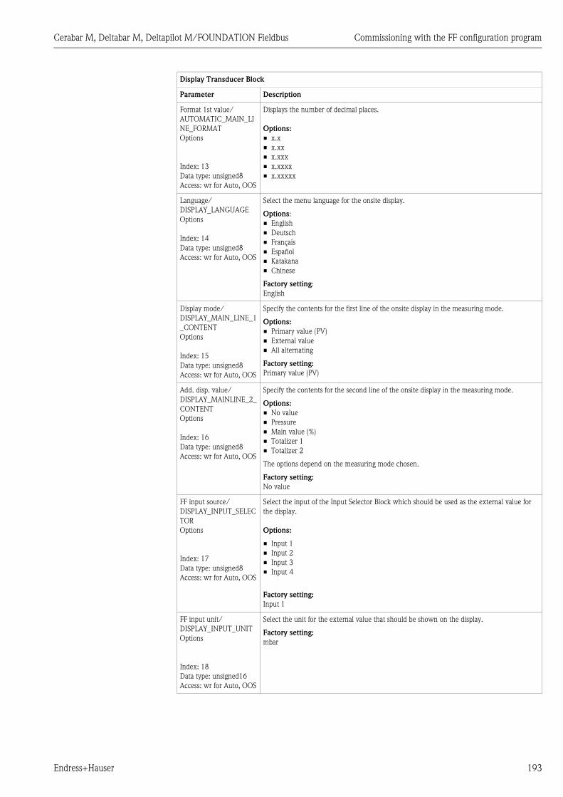
Cerabar M, Deltabar M, Deltapilot M/FOUNDATION Fieldbus Commissioning with the FF configuration program
Endress+Hauser 193
Format 1st value/
AUTOMATIC_MAIN_LI
NE_FORMAT
Options
Index: 13
Data type: unsigned8
Access: wr for Auto, OOS
Displays the number of decimal places.
Options:
• x.x
• x.xx
• x.xxx
• x.xxxx
• x.xxxxx
Language/
DISPLAY_LANGUAGE
Options
Index: 14
Data type: unsigned8
Access: wr for Auto, OOS
Select the menu language for the onsite display.
Options:
• English
• Deutsch
• Français
• Español
• Katakana
• Chinese
Factory setting:
English
Display mode/
DISPLAY_MAIN_LINE_1
_CONTENT
Options
Index: 15
Data type: unsigned8
Access: wr for Auto, OOS
Specify the contents for the first line of the onsite display in the measuring mode.
Options:
• Primary value (PV)
• External value
• All alternating
Factory setting:
Primary value (PV)
Add. disp. value/
DISPLAY_MAINLINE_2_
CONTENT
Options
Index: 16
Data type: unsigned8
Access: wr for Auto, OOS
Specify the contents for the second line of the onsite display in the measuring mode.
Options:
• No value
• Pressure
• Main value (%)
• Totalizer 1
• Totalizer 2
The options depend on the measuring mode chosen.
Factory setting:
No value
FF input source/
DISPLAY_INPUT_SELEC
TOR
Options
Index: 17
Data type: unsigned8
Access: wr for Auto, OOS
Select the input of the Input Selector Block which should be used as the external value for
the display.
Options:
• Input 1
• Input 2
• Input 3
• Input 4
Factory setting:
Input 1
FF input unit/
DISPLAY_INPUT_UNIT
Options
Index: 18
Data type: unsigned16
Access: wr for Auto, OOS
Select the unit for the external value that should be shown on the display.
Factory setting:
mbar
Display Transducer Block
Parameter Description

Commissioning with the FF configuration program Cerabar M, Deltabar M, Deltapilot M/FOUNDATION Fieldbus
194 Endress+Hauser
Diagnostic Transducer Block
FF input form./
DISPLAY_INPUT_FORM
AT
Options
Index: 19
Data type: unsigned8
Access: wr for Auto, OOS
Select the format for the external value that should be shown on the display.
Options:
• x.x
• x.xx
• x.xxx
• x.xxxx
• x.xxxxx
Factory setting:
x.x
Device name str./
GENERIC_DEVICE_TYP
E
Display
Index: 20
Data type: unsigned8
Access: read only
Displays the device type (Cerabar M, Deltabar M or Deltapilot M).
Measuring mode/
OPERATING_MODE
Display
Index: 21
Data type: unsigned8
Access: read only
Select the measuring mode.
The operating menu is structured differently depending on the measuring mode selected.
! Note!
If the measuring mode is changed, no conversion takes place. If necessary, the device has to
be recalibrated after the measuring mode has been changed.
Options:
• Pressure
• Level
• Flow
Factory setting:
Pressure
Diagnostic Transducer Block
Parameter Description
Device dialog/DEVICE
DIALOG
Display
Index: 10
Data type: unsigned8
Access: read only
If configuration is unsuitable, this parameter displays a message indicating that a
configuration error is present. The message can indicate which parameter was incorrectly
configured.
Operator code/
S_W_LOCK
Options
Index: 11
Data type: unsigned16
Access: wr for Auto, OOS
Use this function to enter a code to lock or unlock operation.
Options:
• To lock: Enter a number the release code.
• To unlock: Enter the release code.
! Note!
The release code is "0" in the order configuration. Another release code can be defined in the
Code definition/USER_S_W_UNLOCK parameter. If the user has forgotten the release code,
it can be made visible again by entering the number sequence "5864".
Factory setting:
0
Display Transducer Block
Parameter Description

Cerabar M, Deltabar M, Deltapilot M/FOUNDATION Fieldbus Commissioning with the FF configuration program
Endress+Hauser 195
Lockstate/
STATUS_LOCKING
Display
Index: 12
Data type: unsigned8
Access: read only
Displays the current locking status of the device or conditions that can lock the device
(hardware locking, software locking).
DIP switch/
SWITCH_STATUS_LIST
Display
Index: 13
Data type: unsigned8
Access: read only
Displays the DIP switches activated on the electronic insert.
• P1/P2 switch (Deltabar, inputs inversion enabled)
• Lin/sq. switch (Deltabar, flow has been enabled)
• Simulation switch (AI simulation enabled)
• Damping switch (damping enabled)
• HW lock. switch (HW locking enabled)
Diagnostic Transducer Block
Parameter Description

Commissioning with the FF configuration program Cerabar M, Deltabar M, Deltapilot M/FOUNDATION Fieldbus
196 Endress+Hauser
Simulation mode/
SIMULATION_MODE
Options
Index: 14
Data type: unsigned8
Access: OOS
Switch on simulation and select the simulation mode.
Any simulation running is switched off if the measuring mode or level mode (Lin. mode
(037)) is changed.
Options:
• None
• Pressure
• Flow (only differential pressure transmitter)
• Level
• Tank content
• Alarm/warning
Cerabar M and Deltapilot M:
P01-xxxxxxxx-05-xx-xx-en-005
Deltabar M:
P01-xxxxxxxx-05-xx-xx-en-006
Factory setting:
None
Simulation unit/
SIMULATION_UNIT
Display
Index: 15
Data type:
Access: read only
Displays the unit of the simulation value (depends on the measuring mode selected).
Simulated Value/
SIMULATED_VALUE
Entry
Index: 16
Data type: float
Access: OOS
Enter the simulation value.
Prerequisite:
• Simulation/SIMULATION_MODE = Pressure, flow (Deltabar), level or tank content.
Diagnostic Transducer Block
Parameter Description
P PVAnalogInputBlock
Simulation value pressure
Transducer Block
– Simulation value level– Simulation value tank content
Sensor
Pressure
LevelDampingPositionadjust-ment
Sensortrim
Electr.Delta P.
PV = Primary Value
P PVAnalogInputBlock
Simulation value pressure
Transducer Block
– Simulation value level– Simulation value tank content
Sensor
Pressure
LevelDampingPositionadjust-ment
Sensortrim
Flow
Simulation value flow
PV = Primary Value

Cerabar M, Deltabar M, Deltapilot M/FOUNDATION Fieldbus Commissioning with the FF configuration program
Endress+Hauser 197
Sim. error no./
ALARM_SIMULATION_
VALUE
Entry
Index: 17
Data type: unsigned16
Access: OOS
Enter the message number for simulation.
See also these Operating Instructions, Section 10.1 "Messages", "Code" table column.
Prerequisite:
• Simulate/SIMULATE = Alarm/warning
Value when switched on:
485 "Simulation value" (simulation active)
Status/DEVICE_STATUS
Display
Index: 18
Data type: unsigned8
Access: read only
Provides information on the current status of the device.
Diagnostic code/
ACTUAL_HIGHEST_ALA
RM
Display
Index: 19
Data type: unsigned16
Access: read only
Displays the highest active warning/error message.
Instructions/
ACTUAL_MAINTENAN
CE_INSTRUCT
Display
Index: 20
Data type: unsigned16
Access: read only
Instructions for resolving the highest active warning/error message.
Last diag. code/
LAST_ALARM_INFO_IO
Display
Index: 21
Data type: unsigned16
Access: read only
Last rectified error message. Equivalent to the first entry in the Last diag. code table
(logbook).
Reset logbook/
RESET_ALARM_HISTOR
Y
Index: 22
Data type: unsigned8
Access: wr for Auto, OOS
Parameter for deleting the logbook entries.
Options:
• Abort
• Reset
Factory setting:
Abort
Actual errors/
DIAG_ALARM_TABLE
Display
Index: 23
Data type: OctetString8
Access: read only
Bit field summary of active alarms/warnings.
Diagnostic Transducer Block
Parameter Description

Commissioning with the FF configuration program Cerabar M, Deltabar M, Deltapilot M/FOUNDATION Fieldbus
198 Endress+Hauser
Operating hours/
OPERATING_HOURS_V
ALUE
Display
Index: 24
Data type: unsigned32
Access: read only
Displays the hours of operation.
Diagnostic code/
ACTUAL_HIGHEST_ALA
RM
Display
Index: 25
Data type: record
Access: read only
Table displaying the 10 current active alarms/warnings.
Instructions/
ACTUAL_MAINTENAN
CE_INSTRUCT_INFO
Display
Index: 26
Data type: record
Access: read only
Table displaying the instructions for the current active alarms/warnings.
Last diag. code/
LAST_ALARM_INFOS
Display
Index: 27
Data type: record
Access: wr for Auto, OOS
Table displaying the last 10 current rectified alarms/warnings.
Reset/
RESET_INPUT_VALUE
Entry
Index: 28
Data type: unsigned16
Access: wr for Auto, OOS
Reset parameters completely or partially to the factory values or order configuration,
ä 50, "Resetting to factory settings (reset)".
Factory setting:
0
Config. Recorder/
CONFIGURATION_
COUNTER
Display
Index: 29
Data type: unsigned16
Access: read only
Displays the configuration counter.
This counter is increased by 1 every time a configuration parameter or group is changed.
The counter counts up to 65535 and then starts again at 0.
Alarm behav. P/
UNDER_OVER_PRESSU
RE_BEHAVIOR
Options
Index: 30
Data type: unsigned8
Access: OOS
This parameter specifies how the unit should react if the sensor limit is exceeded or
undershot.
Options:
• Warning
• Alarm
Factory setting
Warning
Diagnostic Transducer Block
Parameter Description

Cerabar M, Deltabar M, Deltapilot M/FOUNDATION Fieldbus Commissioning with the FF configuration program
Endress+Hauser 199
8.12.4 Analog Input Block (function block)
Analog Input Block
Parameter Description
Static Revision/ST_REV
Display
Index: 1
Data type: usigned16
Access: read only
Displays the counter for static parameters of the Analog Input Block.
The counter is incremented by one with each change of a static parameter of the Analog
Input Block. The counter counts up to 65535 and then starts again at zero.
Tag Description/
TAG_DESC
Entry
Index: 2
Data type: octet string
Access: wr for Auto, OOS
Enter a description for the related block or the measuring point e.g. TAG number
(max. 32 alphanumeric characters).
Strategy/STRATEGY
Entry
Index: 3
Data type: unsigned16
Access: auto, man, OOS
Enter user-specific value for grouping and thus faster evaluation of the blocks.
Grouping takes place by entering the same numerical value for the Strategy/STRATEGY
parameter of the block in question.
Input range:
0...65535
Factory setting:
0
Alert Key/ALERT_KEY
Entry
Index: 4
Data type: unsigned8
Access: auto, man, OOS
Enter the identification number for the measuring device or for each individual block.
The control level uses this identification number to sort alarm and event messages and
initiate other processing steps.
Input range:
1...255
Factory setting:
0
Block Mode/MODE_BLK
Selection, display
Index: 5
Data type: DS-69
Access: auto, man, OOS
The Block Mode/MODE_BLK parameter is a structured parameter consisting of four
elements. The Analog Input Block supports the "Auto" (automatic), "Man" (value and status
of the OUT parameter can be specified directly by the operator) and OOS (out of service)
modes.
TARGET
• Change the block mode.
ACTUAL
• Displays the current block mode.
PERMITTED
• Displays the modes supported by the block.
NORMAL
• Displays the block mode during standard operation.

Commissioning with the FF configuration program Cerabar M, Deltabar M, Deltapilot M/FOUNDATION Fieldbus
200 Endress+Hauser
Block Error/BLOCK_ERR
Display
Index: 6
Data type: bit string
Access: read only
Displays the active block error.
Possibilities:
• Out of service (OOS):
– The Analog Input Block is in the OOS block mode.
– The Resource Block is in the OOS block mode.
• Simulation active: DIP switch 2 "Simulation" on the electronic insert is set to "on",
i.e. simulation is possible.
– The simulation mode for the Analog Input Block is active. ä 201, Simulate/
SIMULATE parameter description.
• Input failure: The input value transmitted by the Pressure or DP_Flow Transducer Block is
not valid (BAD status). This could be due to the following:
– The Pressure or DP_Flow Transducer Block is in the OOS block mode.
– A device error is present. In the Diagnosis Transducer Block, the Diagnostic code
parameter displays an error code. See also these Operating Instructions, Section 10.1
"Messages".
! Note!
The "Input failure" block error is relayed to downstream function blocks or high-order
process control systems by means of the BAD status of the output value of the OUT Analog
Input Block.
• Block configuration error: There is a configuration error in the Analog Input Block. This
could be due to the following:
– By means of the Transducer Scale/XD_SCALE parameter, a unit was selected that does
not suit the input value configured in the Channel/CHANNEL parameter.
– No valid input value was selected by means of the Channel/CHANNEL parameter.
ä 202, Channel/CHANNEL parameter description.
– An unsuitable linearization mode was selected via the Linearization Type/L_TYPE
parameter. ä 203, Linearization Type/L_TYPE parameter description.
– The "Direct" linearization mode was selected by means of the Linearization Type/
L_TYPE parameter. The scaling for the Transducer Scale/XD_SCALE and Output
Scale/OUT_SCALE parameters do not match.
– If you assign the same process variable, such as "Primary value", to two Analog Input
Blocks, the same scaling values and units have to be set for both blocks.
Process Value/PV
Display
Index: 7
Data type: DS-65
Access: read only
The PV parameter is a structured parameter consisting of two elements.
VALUE
• Displays the process variable used for block execution
STATUS
• Displays the status of the process variable.
! Note!
The unit used by the Output Scale/OUT_SCALE parameter is accepted.
Output/OUT
Display, entry
Index: 8
Data type: DS-65
Access: auto, man, OOS
The Output/OUT parameter is a structured parameter consisting of two elements.
VALUE
• Displays the output value of the Analog Input Block.
STATUS
• Displays the status of the Output/OUT value.
! Note!
• The output value Output/OUT is also transmitted if it is outside the scaling range of
Output Scale/OUT_SCALE.
• The unit used by the Output Scale/OUT_SCALE parameter is accepted.
• If the "MAN" (manual) block mode was selected by means of the Block Mode/
MODE_BLK parameter, the output value Output/OUT and its status can be specified
manually here.
Analog Input Block
Parameter Description
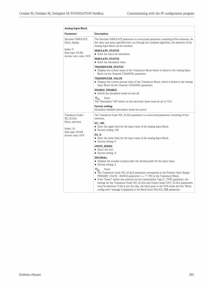
Cerabar M, Deltabar M, Deltapilot M/FOUNDATION Fieldbus Commissioning with the FF configuration program
Endress+Hauser 201
Simulate/SIMULATE
Entry, display
Index: 9
Data type: DS-82
Access: auto, man, OOS
The Simulate/SIMULATE parameter is a structured parameter consisting of five elements. As
the value and status specified here run through the complete algorithm, the behavior of the
Analog Input Block can be checked.
SIMULATE_STATUS
• Enter the status for simulation.
SIMULATE_STATUS
• Enter the simulation value.
TRANSDUCER_STATUS
• Displays the current status of the Transducer Block which is linked to the Analog Input
Block via the Channel/CHANNEL parameter.
TRANSDUCER_VALUE
• Displays the current process value of the Transducer Block, which is linked to the Analog
Input Block via the Channel/CHANNEL parameter.
ENABLE_DISABLE
• Switch the simulation mode on and off.
! Note!
The "Simulation" DIP switch on the electronic insert must be set to "On".
Factory setting:
Simulation disabled (simulation mode not active)
Transducer Scale/
XD_SCALE
Entry, selection
Index: 10
Data type: DS-68
Access: man, OOS
The Transducer Scale/XD_SCALE parameter is a structured parameter consisting of four
elements.
EU_100:
• Enter the upper limit for the input value of the Analog Input Block.
• Factory setting: 100
EU_0:
• Enter the lower limit for the input value of the Analog Input Block.
• Factory setting: 0
UNITS_INDEX:
• Select the unit.
• Factory setting: %
DECIMAL:
• Displays the number of places after the decimal point for the input value.
• Factory setting: 2
! Note!
• The Transducer Scale/XD_SCALE parameter corresponds to the Primary Value Range/
PRIMARY_VALUE_ RANGE parameter ( ä 170) in the Transducer Block.
• If the "Direct" option was selected via the Linearization Type/L_TYPE parameter, the
settings for the Transducer Scale/XD_SCALE and Output Scale/OUT_SCALE parameters
must be identical. If this is not the case, the block goes to the OOS mode and the "Block
config error" message is displayed in the Block Error/BLOCK_ERR parameter.
Analog Input Block
Parameter Description
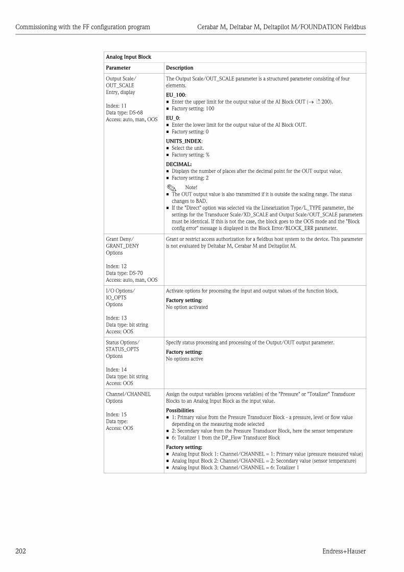
Commissioning with the FF configuration program Cerabar M, Deltabar M, Deltapilot M/FOUNDATION Fieldbus
202 Endress+Hauser
Output Scale/
OUT_SCALE
Entry, display
Index: 11
Data type: DS-68
Access: auto, man, OOS
The Output Scale/OUT_SCALE parameter is a structured parameter consisting of four
elements.
EU_100:
• Enter the upper limit for the output value of the AI Block OUT ( ä 200).
• Factory setting: 100
EU_0:
• Enter the lower limit for the output value of the AI Block OUT.
• Factory setting: 0
UNITS_INDEX:
• Select the unit.
• Factory setting: %
DECIMAL:
• Displays the number of places after the decimal point for the OUT output value.
• Factory setting: 2
! Note!
• The OUT output value is also transmitted if it is outside the scaling range. The status
changes to BAD.
• If the "Direct" option was selected via the Linearization Type/L_TYPE parameter, the
settings for the Transducer Scale/XD_SCALE and Output Scale/OUT_SCALE parameters
must be identical. If this is not the case, the block goes to the OOS mode and the "Block
config error" message is displayed in the Block Error/BLOCK_ERR parameter.
Grant Deny/
GRANT_DENY
Options
Index: 12
Data type: DS-70
Access: auto, man, OOS
Grant or restrict access authorization for a fieldbus host system to the device. This parameter
is not evaluated by Deltabar M, Cerabar M and Deltapilot M.
I/O Options/
IO_OPTS
Options
Index: 13
Data type: bit string
Access: OOS
Activate options for processing the input and output values of the function block.
Factory setting:
No option activated
Status Options/
STATUS_OPTS
Options
Index: 14
Data type: bit string
Access: OOS
Specify status processing and processing of the Output/OUT output parameter.
Factory setting:
No options active
Channel/CHANNEL
Options
Index: 15
Data type:
Access: OOS
Assign the output variables (process variables) of the "Pressure" or "Totalizer" Transducer
Blocks to an Analog Input Block as the input value.
Possibilities
• 1: Primary value from the Pressure Transducer Block - a pressure, level or flow value
depending on the measuring mode selected
• 2: Secondary value from the Pressure Transducer Block, here the sensor temperature
• 6: Totalizer 1 from the DP_Flow Transducer Block
Factory setting:
• Analog Input Block 1: Channel/CHANNEL = 1: Primary value (pressure measured value)
• Analog Input Block 2: Channel/CHANNEL = 2: Secondary value (sensor temperature)
• Analog Input Block 3: Channel/CHANNEL = 6: Totalizer 1
Analog Input Block
Parameter Description

Cerabar M, Deltabar M, Deltapilot M/FOUNDATION Fieldbus Commissioning with the FF configuration program
Endress+Hauser 203
Linearization Type/
L_TYPE
Options
Index: 16
Data type: unsigned8
Access: OOS
Select the linearization mode for the input value.
Options:
• Direct: In this setting, the input value bypasses the linearization function and is looped
unchanged with the same unit through the Analog Input function block. With this option,
the scaling and unit for the Transducer Scale/XD_SCALE and Output Scale/OUT_SCALE
parameters must be identical. If this is not the case, the block goes to the OOS mode and
the "Block config error" message is displayed in the Block Error/BLOCK_ERR parameter.
• Indirect: The input value is rescaled linearly via the Transducer Scale/XD_SCALE input
scaling to the desired Output Scale/OUT_SCALE output range.
• Indirect square root: The input value is rescaled via the Transducer Scale/XD_SCALE
parameter and recalculated using a root function. It is then rescaled again to the desired
output range via the Output Scale/OUT_SCALE parameter.
Factory setting:
Direct
Low Cutoff/LOW_CUT
Entry
Index: 17
Data type: float
Access: auto, man, OOS
Enter the limit value for the low flow cut off. If the converted measured value is below this
limit value, the Process Value/PV parameter displays "0".
! Note!
This parameter is only active if the "Low cutoff" option was activated via the I/O Options/
IO_OPTS parameter.
Input range:
Range and unit of Output Scale/OUT_SCALE ( ä 202).
Factory setting:
0
Process value filter time/
PV_FTIME
Entry
Index: 18
Data type: float
Access: auto, man, OOS
Enter the filter time constant for the 1st order digital filter. This time is required in order for
63% of a change in the controlled variable IN to have an effect on the value of Process Value/
PV.
P01-xxxxxxxx-05-xx-xx-xx-021
Factory setting:
0 s
Field Value/
FIELD_VALUE
Display
Index: 19
Data type:
Access: read only
The Field Value/FIELD_VALUE parameter is a structured parameter consisting of two
elements.
VALUE
• Displays the process variables after input scaling of the Analog Input Block. The value
relates to a percentage of the Transducer Scale/XD_SCALE input range and is replaced by
the simulation value when simulation is active.
STATUS
• Displays the current status.
Analog Input Block
Parameter Description
[s]t
PV
IN
PV_FTIME
63 %

Commissioning with the FF configuration program Cerabar M, Deltabar M, Deltapilot M/FOUNDATION Fieldbus
204 Endress+Hauser
Update Event/
UPDATE_EVT
Display
Index: 20
Data type: DS-73
Access: read only
The Update Event/UPDATE_EVT parameter is a structured parameter consisting of five
elements.
ACKNOWLEDGED
• This element is set to "Unacknowledged" as soon as a static parameter changes.
REPORTED
• Displays the date and time when the message was generated.
TIME_STAMP
• Displays the date and time when a static parameter was changed.
STATIC_REVISION
• This revision counter is increased with the alarm.
RELATIVE_INDEX
• Displays the altered parameter in the form of the relative index. See also this Table,
"Parameter, Index" column.
Block Alarm/
BLOCK_ALM
Display, selection
Index: 21
Data type: DS-72
Access: auto, man, OOS
The Block Alarm/BLOCK_ALM parameter is a structured parameter consisting of five
elements.
UNACKNOWLEDGED
• If the "Deactivated" option was selected for the alarm that occurred by means of the
Acknowledge Option/ACK_OPTION parameter, this alarm can only be acknowledged by
means of this element.
ALARM_STATE
• Use this function to display the current block condition with information on pending
configuration, hardware or system errors. The following block alarm messages are possible
with the Analog Input Block:
– Simulate active
– Input failure
– Block config error
– Out of service
TIME_STAMP
• Displays the time when the alarm occurred.
SUB_CODE
• Displays the reason why the alarm was reported.
VALUE
• Displays the value of the corresponding parameter at the time the alarm was reported.
Alarm Summary/
ALARM_SUM
Display, selection
Index: 22
Data type: DS-74
Access: auto; man, OOS
The Alarm Summary/ALARM_SUM parameter is a structured parameter consisting of four
elements.
CURRENT
• Displays the current status of the process alarms in the Analog Input Block. The following
alarms are possible: HiHiAlm, HiAlm, LoLoAlm, LoAlm and BlockAlm.
UNACKNOWLEDGED
• Displays the process alarms not confirmed.
UNREPORTED
• Displays the process alarms not reported.
DISABLED
• Possibility of deactivating process alarms.
Analog Input Block
Parameter Description
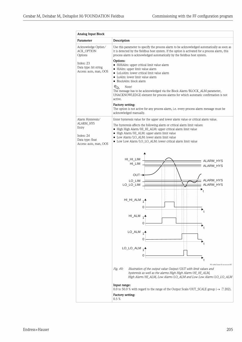
Cerabar M, Deltabar M, Deltapilot M/FOUNDATION Fieldbus Commissioning with the FF configuration program
Endress+Hauser 205
Acknowledge Option/
ACK_OPTION
Options
Index: 23
Data type: bit string
Access: auto, man, OOS
Use this parameter to specify the process alarm to be acknowledged automatically as soon as
it is detected by the fieldbus host system. If the option is activated for a process alarm, this
process alarm is acknowledged automatically by the fieldbus host system.
Options:
• HiHiAlm: upper critical limit value alarm
• HiAlm: upper limit value alarm
• LoLoAlm: lower critical limit value alarm
• LoAlm: lower limit value alarm
• BlockAlm: block alarm
! Note!
The message has to be acknowledged via the Block Alarm/BLOCK_ALM parameter,
UNACKNOWLEDGE element for process alarms for which automatic confirmation is not
active.
Factory setting:
The option is not active for any process alarm, i.e. every process alarm message must be
acknowledged manually.
Alarm Hysteresis/
ALARM_HYS
Entry
Index: 24
Data type: float
Access: auto, man, OOS
Enter hysteresis value for the upper and lower alarm value or critical alarm value.
The hysteresis affects the following alarm or critical alarm limit values:
• High High Alarm/HI_HI_ALM: upper critical alarm limit value
• High Alarm/HI_ALM: upper alarm limit value
• Low Alarm/LO_ALM: lower alarm limit value
• Low Low Alarm/LO_LO_ALM: lower critical alarm limit value
P01-xMx7xxxx-05-xx-xx-xx-007
Fig. 49: Illustration of the output value Output/OUT with limit values and
hysteresis as well as the alarms High High Alarm/HI_HI_ALM,
High Alarm/HI_ALM, Low Alarm/LO_ALM and Low Low Alarm/LO_LO_ALM
Input range:
0.0 to 50.0 % with regard to the range of the Output Scale/OUT_SCALE group ( ä 202).
Factory setting:
0.5 %
Analog Input Block
Parameter Description
t
t
1
0
t
1
0
ALARM_HYS
ALARM_HYS
ALARM_HYS
ALARM_HYS
t
1
0
t
HI_ALM
LO_ALM
HI_LIM
LO_LIM
OUT
HI_HI_LIM
LO_LO_LIM
HI_HI_ALM
LO_LO_ALM1
0

Commissioning with the FF configuration program Cerabar M, Deltabar M, Deltapilot M/FOUNDATION Fieldbus
206 Endress+Hauser
High High Priority/
HI_HI_PRI
Entry
Index: 25
Data type: unsigned8
Access: auto, man, OOS
Specify how the system should react if the High High Limit/HI_HI_LIM limit value
( ä 206 ) is overshot.
Input range:
• 0...15
• 0: The alarm is suppressed.
• 1: The alarm is detected by the system. No notification is issued.
• 2: Reserved for block alarms.
• 3-7: Informative alarm with increasing priority,
3: Low priority, 7: High priority
• 8-15: Critical alarm with increasing priority,
8: Low priority, 15: High priority
Factory setting:
0
High High Limit/
HI_HI_LIM
Entry
Index: 26
Data type: float
Access: auto, man, OOS
Enter upper critical limit value.
Input range:
Range and units of Output Scale/OUT_SCALE ( ä 202)
Factory setting:
+INF
High Priority/HI_PRI
Entry
Index: 27
Data type: unsigned8
Access: auto, man, OOS
Specify how the system should react if the High Limit/HI_LIM limit value ( ä 206 ) is
overshot.
Input range:
• 0...15
• 0: The alarm is suppressed.
• 1: The alarm is detected by the system. No notification is issued.
• 2: Reserved for block alarms.
• 3-7: Informative alarm with increasing priority,
3: Low priority, 7: High priority
• 8-15: Critical alarm with increasing priority,
8: Low priority, 15: High priority
Factory setting:
0
High Limit/HI_LIM
Entry
Index: 28
Data type: float
Access: auto, man, OOS
Enter upper limit value.
Input range:
Range and units of Output Scale/OUT_SCALE ( ä 202)
Factory setting:
+INF
Low Priority/LO_PRI
Entry
Index: 29
Data type: unsigned8
Access: auto, man, OOS
Specify how the system should react if the Low Limit/LO_LIM limit value ( ä 206) is
undershot.
Input range:
• 0...15
• 0: The alarm is suppressed.
• 1: The alarm is detected by the system. No notification is issued.
• 2: Reserved for block alarms.
• 3-7: Informative alarm with increasing priority,
3: Low priority, 7: High priority
• 8-15: Critical alarm with increasing priority,
8: Low priority, 15: High priority
Factory setting:
0
Low Limit/LO_LIM
Entry
Index: 30
Data type: float
Access: auto, man, OOS
Enter lower limit value.
Input range:
Range and units of Output Scale/OUT_SCALE ( ä 202)
Factory setting:
–INF
Analog Input Block
Parameter Description

Cerabar M, Deltabar M, Deltapilot M/FOUNDATION Fieldbus Commissioning with the FF configuration program
Endress+Hauser 207
Low Low Priority/
LO_LO_PRI
Entry
Index: 31
Data type: unsigned8
Access: auto, man, OOS
Specify how the system should react if the Low Low Limit/LO_LO_LIM limit value
( ä 207) is undershot.
Input range:
• 0...15
• 0: The alarm is suppressed.
• 1: The alarm is detected by the system. No notification is issued.
• 2: Reserved for block alarms.
• 3-7: Informative alarm with increasing priority,
3: Low priority, 7: High priority
• 8-15: Critical alarm with increasing priority,
8: Low priority, 15: High priority
Factory setting:
0
Low Low Limit/
LO_LO_LIM
Entry
Index: 32
Data type: float
Access: auto, man, OOS
Enter lower critical limit value.
Input range:
Range and units of Output Scale/OUT_SCALE ( ä 207)
Factory setting:
–INF
Low Low Alarm/
LO_LO_ALM
Display, selection
Index: 33
Data type: DS-71
Access: auto, man, OOS
Status display for the Low Low Limit/LO_LO_LIM limit value ( ä 207).
High High Alarm/
HI_HI_ALM
Display, selection
Index: 33
Data type: DS-71
Access: auto, man, OOS
Status display for the High High Limit/HI_HI_LIM limit value ( ä 206).
High Alarm/HI_ALM
Display, selection
Index: 34
Data type: DS-71
Access: auto, man, OOS
Status display for the High Limit/HI_LIM limit value ( ä 206).
Low Alarm/LO_ALM
Display, selection
Index: 35
Data type: DS-71
Access: auto, man, OOS
Status display for the Low Limit/LO_LIM limit value ( ä 206).
Analog Input Block
Parameter Description

Commissioning with the FF configuration program Cerabar M, Deltabar M, Deltapilot M/FOUNDATION Fieldbus
208 Endress+Hauser
Fsafe type/FSAFE_TYPE
Options
Index: 37
Data type: unsigned8
Access: man, OOS
If the Analog Input Block receives an input value or simulation value with the status BAD,
the Analog Input Block continues working with the failsafe mode defined by means of this
parameter.
The following options are available by means of the Fsafe type/FSAFE_TYPE parameter:
• Last Good Value
The last valid value is used for further processing with the status UNCERTAIN.
• Fail Safe Value
The value specified by means of the Fsafe value/FSAFE_VALUE parameter is used for
further processing with the status UNCERTAIN. See this table, Fsafe type/
FSAFE_TYPE parameter description.
• Wrong Value
The current value is used for further processing with the status BAD.
! Note!
The failsafe mode is also activated if the "Out of service" option was selected by means of the
Block Mode/MODE_BLK parameter, "Target" element.
Factory setting:
Fail Safe Value
Fsafe value/
FSAFE_VALUE
Entry
Index: 38
Data type: float
Access: wr for Auto, OOS,
Man
Enter the value for the "Fail Safe Value" option selected via the Fsafe type/FSAFE_TYPE
parameter.
See also this table, Fsafe type/FSAFE_TYPE parameter description.
Factory setting:
0
High High Alarm Output
Discrete/
HIHI_ALM_OUT_D
Index: 39
Data type: DS66
Access: wr for Auto, OOS,
Man
Digital outputs (1 or 0) for limit value monitoring. If the Process Value/PV High High
Limit/HI_HI_LIM, the output is set to "1".
High alarm output
discrete/
HI_ALM_OUT_D
Index: 40
Data type: DS66
Access: wr for Auto, OOS,
Man
Digital outputs (1 or 0) for limit value monitoring. If the Process Value/PV High Limit/
HI_LIM, the output is set to "1".
Low alarm output
discrete/
LO_ALM_OUT_D
Index: 41
Data type: DS66
Access: wr for Auto, OOS,
Man
Digital outputs (1 or 0) for limit value monitoring. If the Process Value/PV Low Low Limit/
LO_LO_LIM, the output is set to "1".
Low Low Alarm Output
Discrete/LOLO_ALM_
OUT_D
Index: 42
Data type: DS66
Access: wr for Auto, OOS,
Man
Digital outputs (1 or 0) for limit value monitoring. If the Process Value/PV Low Limit/
LO_LIM, the output is set to "1".
Analog Input Block
Parameter Description

Cerabar M, Deltabar M, Deltapilot M/FOUNDATION Fieldbus Commissioning with the FF configuration program
Endress+Hauser 209
8.12.5 Backup or duplicate device data
The device has no memory module. With an operating tool based on FDT technology (e.g.
FieldCare), you have the following options (see parameter "Download select" ä 113 in operating
menu or via Resource block ä 166):
• Saving/rescuing configuration data
• Duplicating instrument configurations
• Transferring all relevant parameters when replacing electronic inserts.
For more information, read the operating manual for the FieldCare operating program.
Select Alarm Mode/
ALARM_MODE
Index: 43
Data type: DS66
Access: wr for Auto, OOS,
Man
Facilitates alarm mode settings for the Alarm Output Discrete/ALM_OUT_D parameter.
Options
• Low Cutoff/LOW_CUT
• HiHi or LoLo Alarm activates ALARM_OUT_D/HIHI_LOLO
• Hi or Lo Alarm activates ALARM_OUT_D/HI_LO
Alarm Output Discrete/
ALM_OUT_D
Index: 44
Data type: DS-66
Access: wr for Auto, OOS,
Man
The Alarm Output Discrete/ALM_OUT_D parameter comprises the 4 alarms (LO, LOLO,
HI, HIHI). The 3 values make it possible to view the current, activated alarm depending on
the alarm selected.
Options:
• LOW_CUT alarm (default): The ALM_OUT_D output returns 1 if the LOW_CUT function
restricts the measured value to 0. Otherwise the ALM_OUT_D output is 0.
• HIHI/LOLO collective alarm: The ALM_OUT_D output returns 1 if the measured value
corresponds to the HIHI limit value or overshoots this value if the measured value
corresponds to the LOLO limit value or undershoots this value. The output returns 0 if the
measured value is between the limit values HIHI and LOLO.
• HI/LO collective alarm: The ALM_OUT_D output returns 1 if the measured value
corresponds to the HI limit value or overshoots this value if the measured value
corresponds to the LO limit value or undershoots this value. The output returns 0 if the
measured value is between the limit values HI and LO.
Block Error Description/
BLOCK_ERR_DESC_1
Index: 45
Data type: unsigned32
Access: wr for Auto, OOS,
Man
Detailed description of the errors that occur within the block.
Error messages:
• RS_BLOCK in OOS
• Block not scheduled
• Channel undefined
• L-Type undefined
• AI / TRD unit inconsistent
Analog Input Block
Parameter Description

Maintenance Cerabar M, Deltabar M, Deltapilot M/FOUNDATION Fieldbus
210 Endress+Hauser
9 Maintenance
Deltabar M requires no maintenance.
For Cerabar M and Deltapilot M keep the pressure compensation and GORE-TEX® filter (1) free
from contamination.
P01-xMx5xxxx-17-xx-xx-xx-000.
9.1 Cleaning instructions
Endress+Hauser offer flushing rings as accessories to clean process isolating diaphragms without
taking the transmitters out of the process.
For further information please contact your local Endress+Hauser Sales Center.
9.1.1 Cerabar M PMP55
We recommend you perform CIP (cleaning in place (hot water)) before SIP (sterilization in place
(steam)) for pipe diaphragm seals. A frequent use of sterilization in place (SIP) will increase the stress
on the process isolating diaphragm. Under unfavorable circumstances in the long term view we
cannot exclude that a frequent temperature change could lead to a material fatigue of the process
isolating diaphragm and possibly to a leakage.
9.2 Exterior cleaning
Please note the following points when cleaning the device:
• The cleaning agents used should not corrode the surface and the seals.
• Mechanical damage to the process isolating diaphragm, e.g. due to pointed objects, must be
avoided.
• Observe the degree of protection of the device. See the nameplate if necessary ( ä 6 ff).
11

Cerabar M, Deltabar M, Deltapilot M/FOUNDATION Fieldbus Troubleshooting
Endress+Hauser 211
10 Troubleshooting
10.1 Messages
The following table lists the messages that can occur. The Diagnostic code/
ACTUAL_HIGHEST_ALARM parameter displays the message with the highest priority. The device
has four different status information codes according to NE107:
• F = failure
• M (warning) = maintenance required
• C (warning) = function check
• S (warning) = out of specification (deviations from the permitted ambient or process conditions
determined by the device with the self-monitoring function, or errors in the device itself indicate
that the measuring uncertainty is greater than what would be expected under normal operating
conditions).
Message display:
• Local operation:
– The measured value display shows the message with the highest priority.
– The Diagnostic code/ACTUAL_HIGHEST_ALARM parameter displays all messages present in
descending order of priority. You can scroll through all the messages pending using the S or O
key.
• FieldCare:
The Diagnostic code/ACTUAL_HIGHEST_ALARM parameter displays the message with the
highest priority.
See the "Priority" column.
• Diagnostic Transducer Block (FF configuration program):
The Diagnostic code/ACTUAL_HIGHEST_ALARM parameter displays the message with the
highest priority. Every message is also output as per the FOUNDATION Fieldbus Specification by
means of the Transducer error/XD_ERROR and Block error/BLOCK_ERROR parameters.
Numbers are given for these parameters in the following table which are explained ä 214.
• You can view a list of the active alarms via the Diagnostic code/ACTUAL_HIGHEST_ALARM
parameter.
• You can view a list of alarms which are no longer active (event log) via the Last diag. code/
LAST_ALARM_INFOS parameter.
Diagnostic
code
Error message XD_ERROR
Value
BLOCK_ERROR
bits
Cause Measure
0 No error – – – –
C484 Error simul. 17 0 – Fault state simulation is switched on, i.e.
the device is not measuring at present.
End the simulation
C485 Measure simul. 17 0 – Simulation is switched on, i.e. the device is
not measuring at present.
End the simulation
C824 Process pressure 20 8 – Overpressure or low pressure present.
– Electromagnetic effects are greater than
specifications in the technical data. This
message normally only appears briefly.
1. Check the pressure value
2. Restart the device
3. Perform a reset
F002 Sens. unknown 20 8 – Sensor does not suit the device (electronic
sensor nameplate).
Contact Endress+Hauser Service
F062 Sensor conn. 20 8 – Cable connection between sensor and main
electronics disconnected.
– Sensor defect.
– Electromagnetic effects are greater than
specifications in the technical data.
1. Check sensor cable
2. Replace electr.
3. Contact Endress+Hauser Service
4. Replace sensor (snap-on Version)

Troubleshooting Cerabar M, Deltabar M, Deltapilot M/FOUNDATION Fieldbus
212 Endress+Hauser
F081 Initialization 20 8 – Cable connection between sensor and main
electronics disconnected.
– Sensor defect.
– Electromagnetic effects are greater than
specifications in the technical data. This
message normally only appears briefly.
1. Perform a reset
2. Check sensor cable
3. Contact Endress+Hauser Service
F083 Permanent mem. 20 8 – Sensor defect.
– Electromagnetic effects are greater than
specifications in the technical data. This
message normally only appears briefly.
1. Restart the device
2. Contact Endress+Hauser Service
F140 Working range P 20 8 – Overpressure or low pressure present.
– Electromagnetic effects are greater than
specifications in the technical data.
– Sensor defect.
1. Check the process pressure
2. Check the sensor range
F261 Electronics 20 8 – Main electronics defective.
– Fault in the main electronics.
1. Restart the device
2. Replace electr.
F282 Data memory 20 9 – Fault in the main electronics.
– Main electronics defective.
1. Restart the device
2. Replace electr.
F283 Permanent mem. 23 11 – Main electronics defective.
– Electromagnetic effects are greater than
specifications in the technical data.
– The supply voltage is disconnected when
writing.
– An error occurred when writing.
1. Perform a reset
2. Replace electr.
F510 Linearization 19 13 – The linearization table is being edited. 1. Conclude entries
2. Select "linear"
F511 Linearization 19 13 – The linearization table consists of less than
2 points.
1. Table too small
2. Corr. table
3. Accept the table
F512 Linearization 19 13 – The linearization table is not monotonic
increasing or decreasing.
1. Tab. not monotonic
2. Corr. table
3. Accept the table
F841 Sensor range 17 8 – Overpressure or low pressure present.
– Sensor defect.
1. Check the pressure value
2. Contact Endress+Hauser Service
F882 Input signal 22 0 – External measured value is not received or
displays a failure status.
1. Check the bus
2. Check source device
3. Check the setting
M002 Sens. unknown 17 8 – Sensor does not suit the device (electronic
sensor nameplate). Device continues
measuring.
Contact Endress+Hauser Service
M283 Permanent mem. 23 11 – Cause as indicated for F283.
– Correct measurement can continue as long
as you do not need the peakhold indicator
function.
1. Perform a reset
2. Replace electr.
M402 Initialization 23 11 – Cause as indicated for F283.
– Correct measurement can continue as long
as you do not need the setpoint function of
the FF function blocks.
1. Wait 2 minutes
2. Restart the device
3. Contact Endress+Hauser Service
M434 Scaling 18 13 – Values for calibration (e.g. lower range
value and upper range value) are too close
together.
– Lower range value and/or upper range
value undershoot or overshoot the sensor
range limits.
– The sensor was replaced and the customer-
specific configuration does not suit the
sensor.
– Unsuitable download carried out.
1. Check the measuring range
2. Check the setting
3. Contact Endress+Hauser Service
Diagnostic
code
Error message XD_ERROR
Value
BLOCK_ERROR
bits
Cause Measure
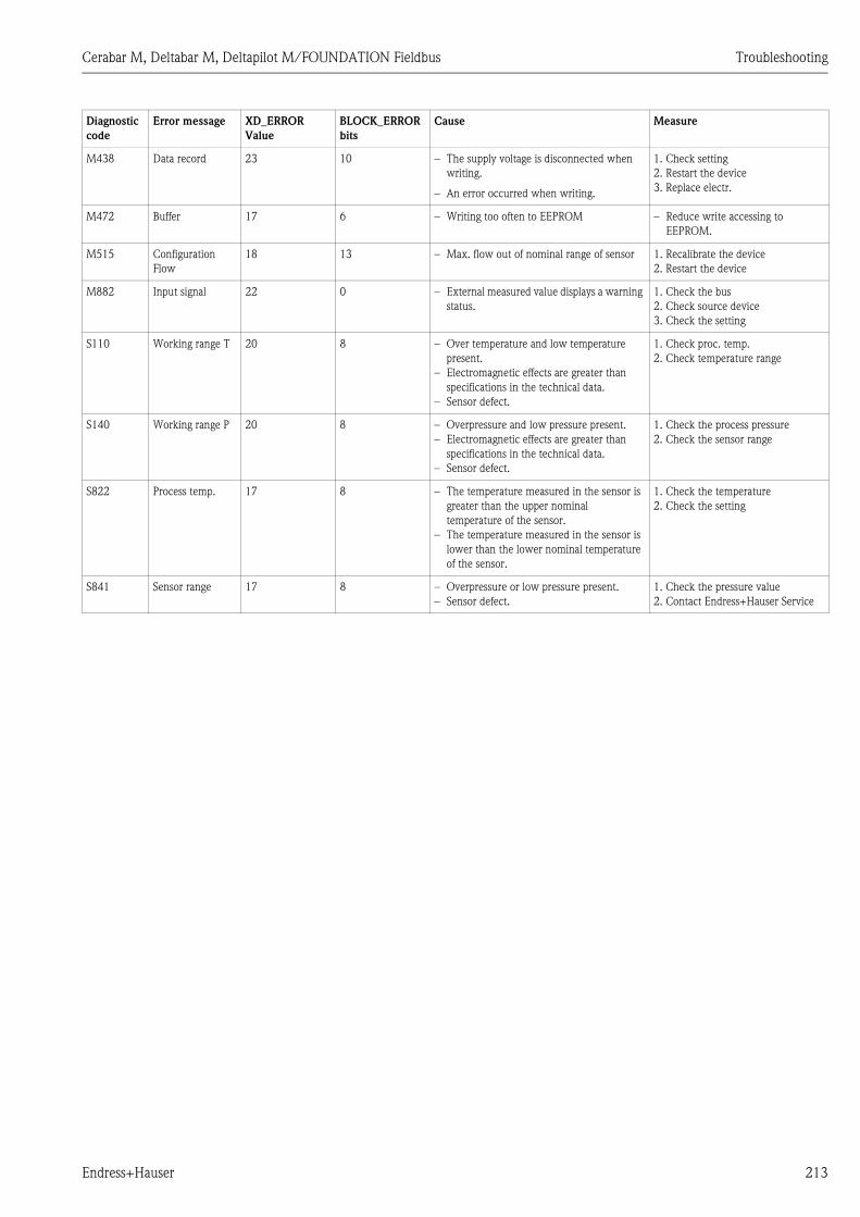
Cerabar M, Deltabar M, Deltapilot M/FOUNDATION Fieldbus Troubleshooting
Endress+Hauser 213
M438 Data record 23 10 – The supply voltage is disconnected when
writing.
– An error occurred when writing.
1. Check setting
2. Restart the device
3. Replace electr.
M472 Buffer 17 6 – Writing too often to EEPROM – Reduce write accessing to
EEPROM.
M515 Configuration
Flow
18 13 – Max. flow out of nominal range of sensor 1. Recalibrate the device
2. Restart the device
M882 Input signal 22 0 – External measured value displays a warning
status.
1. Check the bus
2. Check source device
3. Check the setting
S110 Working range T 20 8 – Over temperature and low temperature
present.
– Electromagnetic effects are greater than
specifications in the technical data.
– Sensor defect.
1. Check proc. temp.
2. Check temperature range
S140 Working range P 20 8 – Overpressure and low pressure present.
– Electromagnetic effects are greater than
specifications in the technical data.
– Sensor defect.
1. Check the process pressure
2. Check the sensor range
S822 Process temp. 17 8 – The temperature measured in the sensor is
greater than the upper nominal
temperature of the sensor.
– The temperature measured in the sensor is
lower than the lower nominal temperature
of the sensor.
1. Check the temperature
2. Check the setting
S841 Sensor range 17 8 – Overpressure or low pressure present.
– Sensor defect.
1. Check the pressure value
2. Contact Endress+Hauser Service
Diagnostic
code
Error message XD_ERROR
Value
BLOCK_ERROR
bits
Cause Measure

Troubleshooting Cerabar M, Deltabar M, Deltapilot M/FOUNDATION Fieldbus
214 Endress+Hauser
Explanation of XD_ERROR and BLOCK_ERROR
• F = failure
• M (warning) = maintenance required
• C (warning) = function check
• S (warning) = out of specification (deviations from the permitted ambient or process conditions
determined by the device with the self-monitoring function, or errors in the device itself indicate
that the measuring uncertainty is greater than what would be expected under normal operating
conditions).
Error type Code XD_ERROR
Value
XD_ERROR Text BLOCK_
ERROR bits
BLOCK_ERROR Text PV Status
F (failure) 2, 62, 81, 83 20 Electronics failure 8 Sensor failure Bad Sensor failure
140 20 Electronics failure 8 Sensor failure Bad Sensor failure
261, 282 20 Electronics failure 9 Memory failure Bad Device failure
283 23 Data integrity error 11 Lost NV data Bad Device failure
510, 511, 512 19 Configuration error 13 Device needs maintenance now Bad Configuration error
841 17 General error 8 Sensor failure Bad Sensor failure
882 22 I/O failure 0 Other Bad Non-specific
(M) warning 2 17 General error 8 Sensor failure Uncertain non-specific
283, 402 23 Data integrity error 11 Lost NV data Uncertain non-specific
434, 515 18 Calibration error 13 Device needs maintenance now Uncertain non-specific
438 23 Data integrity error 10 Lost static data Uncertain non-specific
472 17 General error 6 Device needs maintenance soon Uncertain non-specific
882 22 I/O failure 0 Other Uncertain sub-normal
(C) warning 484, 485 17 General error 0 Other Uncertain non-specific
824 20 Electronics failure 8 Sensor failure Uncertain Non-specific
(S) warning 110 20 Electronics failure 8 Sensor failure Uncertain Sensor conversion not accurate
140 20 Electronics failure 8 Sensor failure Uncertain Sensor conversion not accurate
822 17 General error 8 Sensor failure Uncertain
Sensor conversion not accurate
841 17 General error 8 Sensor failure Uncertain
Sensor conversion not accurate
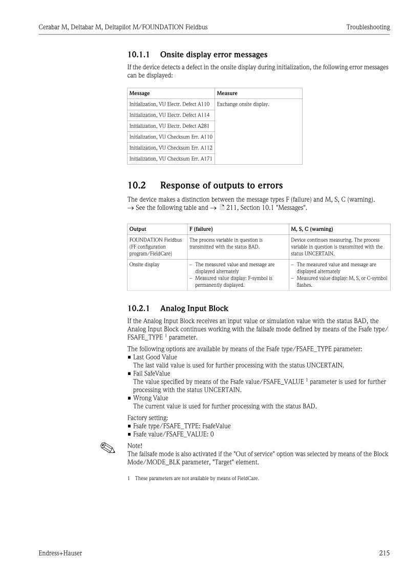
Cerabar M, Deltabar M, Deltapilot M/FOUNDATION Fieldbus Troubleshooting
Endress+Hauser 215
10.1.1 Onsite display error messages
If the device detects a defect in the onsite display during initialization, the following error messages
can be displayed:
10.2 Response of outputs to errors
The device makes a distinction between the message types F (failure) and M, S, C (warning).
See the following table and ä 211, Section 10.1 "Messages".
10.2.1 Analog Input Block
If the Analog Input Block receives an input value or simulation value with the status BAD, the
Analog Input Block continues working with the failsafe mode defined by means of the Fsafe type/
FSAFE_TYPE 1 parameter.
The following options are available by means of the Fsafe type/FSAFE_TYPE parameter:
• Last Good Value
The last valid value is used for further processing with the status UNCERTAIN.
• Fail SafeValue
The value specified by means of the Fsafe value/FSAFE_VALUE 1 parameter is used for further
processing with the status UNCERTAIN.
• Wrong Value
The current value is used for further processing with the status BAD.
Factory setting:
• Fsafe type/FSAFE_TYPE: FsafeValue
• Fsafe value/FSAFE_VALUE: 0
! Note!
The failsafe mode is also activated if the "Out of service" option was selected by means of the Block
Mode/MODE_BLK parameter, "Target" element.
Message Measure
Initialization, VU Electr. Defect A110 Exchange onsite display.
Initialization, VU Electr. Defect A114
Initialization, VU Electr. Defect A281
Initialization, VU Checksum Err. A110
Initialization, VU Checksum Err. A112
Initialization, VU Checksum Err. A171
Output F (failure) M, S, C (warning)
FOUNDATION Fieldbus
(FF configuration
program/FieldCare)
The process variable in question is
transmitted with the status BAD.
Device continues measuring. The process
variable in question is transmitted with the
status UNCERTAIN.
Onsite display – The measured value and message are
displayed alternately
– Measured value display: F-symbol is
permanently displayed.
– The measured value and message are
displayed alternately
– Measured value display: M, S, or C-symbol
flashes.
1 These parameters are not available by means of FieldCare.

Troubleshooting Cerabar M, Deltabar M, Deltapilot M/FOUNDATION Fieldbus
216 Endress+Hauser
10.3 Repair
The Endress+Hauser repair concept provides for measuring devices to have a modular design and
that the customer can also carry out repairs (see ä 216, Section 10.5 "Spare Parts").
! Note!
• For certified devices, please see the "Repair of Ex-certified devices" section.
• For more information on service and spare parts, contact Endress+Hauser Service.
See www.endress.com/worldwide.
10.4 Repair of Ex-certified devices
# Warning!
When repairing Ex-certified devices, please note the following:
• Only specialist personnel or Endress+Hauser may repair certified devices.
• Relevant standards, national hazardous area regulations and safety instructions and certificates
must be observed.
• Only genuine Endress+Hauser spare parts may be used.
• When ordering spare parts, please check the device designation on the nameplate. Identical parts
may only be used as replacements.
• Electronic inserts or sensors already in use in a standard device may not be used as spare parts for
a certified device.
• Carry out repairs according to the instructions. Following a repair, the device must fulfill the
requirements of the specified individual tests.
• A certified device may only be converted to another certified device version by Endress+Hauser.
• All repairs and modifications must be documented.
10.5 Spare Parts
• Some replaceable measuring device components are identified by means of a spare part
nameplate. This contains information about the spare part.
• All the spare parts for the measuring device along with the order code are listed In the W@M
Device Viewer (www.endress.com/deviceviewer) and can be ordered. If available, users can also
download the associated Installation Instructions.
! Note!
Measuring device serial number:
• Located on the device and spare part nameplate.
• Can be read out via the "Serial number" parameter in the "Instrument info" submenu.
10.6 Return
The measuring device must be returned if repairs or a factory calibration are required, or if the
wrong measuring device has been ordered or delivered. According to legal regulations,
Endress+Hauser, as a ISO-certified company, is required to follow certain procedures when
handling returned products that are in contact with process fluids.
To ensure swift, safe and professional device returns, please read the return procedures and
conditions on the Endress+Hauser website at www.services.endress.com/return-material.
10.7 Disposal
When disposing, separate and recycle the device components based on the materials.

Cerabar M, Deltabar M, Deltapilot M/FOUNDATION Fieldbus Troubleshooting
Endress+Hauser 217
10.8 Software history
Device Date Software version Software modifications Operating Instructions
Cerabar M 12.2010 01.00.zz Original software.
Compatible with:
– FieldCare from version 2.08.00
– Field Communicator DXR375 with
Device
Rev.: 1, DD Rev.: 1
BA00384P/00/EN/01.11
71089568
BA00384P/00/EN/02.11
71134596
BA00384P/00/EN/03.11
71134885
BA00384P/00/EN/04.12
71157189
BA00384P/00/EN/05.12
71191310
BA00384P/00/EN/06.14
71241506
BA00384P/00/EN/07.14
71270337
Device Date Software version Software modifications Operating Instructions
Deltabar M 12.2010 01.00.zz Original software.
Compatible with:
– FieldCare from version 2.08.00
– Field Communicator DXR375 with
Device
Rev.: 1, DD Rev.: 1
BA00384P/00/EN/01.11
71089568
BA00384P/00/EN/02.11
71134596
BA00384P/00/EN/03.11
71134885
BA00384P/00/EN/04.12
71157189
BA00384P/00/EN/05.12
71191310
BA00384P/00/EN/06.14
71241506
BA00384P/00/EN/07.14
71270337
Device Date Software version Software modifications Operating Instructions
Deltapilot M 12.2010 01.00.zz Original software.
Compatible with:
– FieldCare from version 2.08.00
– Field Communicator DXR375 with
Device
Rev.: 1, DD Rev.: 1
BA00384P/00/EN/01.11
71089568
BA00384P/00/EN/02.11
71134596
BA00384P/00/EN/03.11
71134885
BA00384P/00/EN/04.12
71157189
BA00384P/00/EN/05.12
71191310
BA00384P/00/EN/06.14
71241506
BA00384P/00/EN/07.14
71270337

Technical data Cerabar M, Deltabar M, Deltapilot M/FOUNDATION Fieldbus
218 Endress+Hauser
11 Technical data
For the technical data, please refer to the Technical Information for Cerabar M TI00436P /
Deltabar M TI00434P / Deltapilot M TI00437P.

Cerabar M, Deltabar M, Deltapilot M/FOUNDATION Fieldbus Index
Endress+Hauser 219
Index
AAlarm messages. . . . . . . . . . . . . . . . . . . . . . . . . . . . . . . . 211
Assignment of Transducer Blocks (CHANNEL) . . . . . . . . . 58
BBlock configuration, delivery status . . . . . . . . . . . . . . 56, 158
Block model, Deltabar S . . . . . . . . . . . . . . . . . . . . . . . . . . 54
CCable specification . . . . . . . . . . . . . . . . . . . . . . . . . . . . . . 34
DDevice addressing . . . . . . . . . . . . . . . . . . . . . . . . . . . . . . . 53
Device identification . . . . . . . . . . . . . . . . . . . . . . . . . . . . . 53
Diaphragm seals, installation instructions . . . . . . . . . . . . . . 14
Diaphragm seals, vacuum application. . . . . . . . . . . . . . . . . 14
Differential pressure measurement in gases and steam . . . . 24
Differential pressure measurement, installation . . . . . . . . . 24
Differential pressure measurement, preparatory steps . . . . . 85
Display . . . . . . . . . . . . . . . . . . . . . . . . . . . . . . . . . . . . . . . 43
EElectrical connection . . . . . . . . . . . . . . . . . . . . . . . . . . . . . 33
Error messages . . . . . . . . . . . . . . . . . . . . . . . . . . . . . . . . 211
FFactory setting. . . . . . . . . . . . . . . . . . . . . . . . . . . . . . . . . . 50
FieldCare . . . . . . . . . . . . . . . . . . . . . . . . . . . . . . . . . . . . . 48
Flow measurement . . . . . . . . . . . . . . . . . . . . . . . . . . . . . . 87
Flow measurement, installation . . . . . . . . . . . . . . . . . . . . . 19
Flow measurement, preparatory steps . . . . . . . . . . . . . . . . 88
FOUNDATION Fieldbus system architecture . . . . . . . . . . . 51
GGeneral structure of the operating menu . . . . . . . . . . . . . . 42
IIncoming acceptance. . . . . . . . . . . . . . . . . . . . . . . . . . . . . 10
Index tables . . . . . . . . . . . . . . . . . . . . . . . . . . . . . . . . . . . 60
Installation instructions for devices with diaphragm seals -
PMP55 . . . . . . . . . . . . . . . . . . . . . . . . . . . . . . . . . . . . . . . 14
Installation instructions for devices without diaphragm seals -
PMP51, PMC51 . . . . . . . . . . . . . . . . . . . . . . . . . . . . . . . . 11
KKeys, local, function . . . . . . . . . . . . . . . . . . . . . . . . . . 41, 45
Keys, local, pressure measuring mode . . . . . . . . . . . . . . . . 64
LLanguage selection . . . . . . . . . . . . . . . . . . . . . . . . . . 65, 135
Level measurement . . . . . . . . . . . . . . . . . . . . . . . 13, 68, 139
Level measurement in an open container . . . . . . . . . . . . . . 22
Level measurement, installation. . . . . . . . . . . . . . . . . . . . . 22
Level measurement, preparatory steps . . . . . . . . . . . . . . . . 90
Linearization . . . . . . . . . . . . . . . . . . . . . . . . . . . . . . . 78, 152
Local display . . . . . . . . . . . . . . . . . . . . . . . . . . . . . . . . . . . 43
Locking operation . . . . . . . . . . . . . . . . . . . . . . . . . . . . 41, 48
MMeasuring arrangement for flow measurement. . . . . . . . . . 19
Measuring mode selection . . . . . . . . . . . . . . . . . . . . . 65, 135
Methods . . . . . . . . . . . . . . . . . . . . . . . . . . . . . . . . . . . . . . 63
Mounting, mounting clamp . . . . . . . . . . . . . . . . . . . . . . . . 29
NNameplate. . . . . . . . . . . . . . . . . . . . . . . . . . . . . . . . . . . . . . 6
Network configuration. . . . . . . . . . . . . . . . . . . . . . . . . . . . 52
Number of devices. . . . . . . . . . . . . . . . . . . . . . . . . . . . . . . 52
OOperating elements, function . . . . . . . . . . . . . . . . . . . . 41, 45
Operating elements, position . . . . . . . . . . . . . . . . . . . . . . . 40
Operating keys, position. . . . . . . . . . . . . . . . . . . . . . . . . . . 40
Overvoltage protection . . . . . . . . . . . . . . . . . . . . . . . . . . . 36
PPipe mounting . . . . . . . . . . . . . . . . . . . . . . . . . . . . 16, 25, 30
Pos. Zero Adjust . . . . . . . . . . . . . . . . . . . . . . . . . . . . 67, 137
Position adjustment, onsite . . . . . . . . . . . . . . . . . . . . . . . . 41
Potential equalization . . . . . . . . . . . . . . . . . . . . . . . . . . . . 35
Pressure measurement in gases . . . . . . . . . . . . . . . . . . . . . 12
Pressure measurement in liquids . . . . . . . . . . . . . . . . . . . . 13
Pressure measurement in steams . . . . . . . . . . . . . . . . . . . . 12
RRepair . . . . . . . . . . . . . . . . . . . . . . . . . . . . . . . . . . . . . . . 216
Repair of Ex-certified devices . . . . . . . . . . . . . . . . . . . . . . 216
Reset . . . . . . . . . . . . . . . . . . . . . . . . . . . . . . . . . . . . . . . . . 50
Returning devices . . . . . . . . . . . . . . . . . . . . . . . . . . . . . . 216
SScaling OUT parameter . . . . . . . . . . . . . . . . . . . . . . . . . . 134
Scope of delivery . . . . . . . . . . . . . . . . . . . . . . . . . . . . . . . . . 9
Separate housing, assembly and mounting . . . . . . . . . . 17, 31
Shielding . . . . . . . . . . . . . . . . . . . . . . . . . . . . . . . . . . . . . . 35
Simulation. . . . . . . . . . . . . . . . . . . . . . . . . . . . . . . . . . . . . 49
Software history. . . . . . . . . . . . . . . . . . . . . . . . . . . . . . . . 217
Spare Parts . . . . . . . . . . . . . . . . . . . . . . . . . . . . . . . . . . . 216
Storage . . . . . . . . . . . . . . . . . . . . . . . . . . . . . . . . . . . . . . . 10
Supply voltage . . . . . . . . . . . . . . . . . . . . . . . . . . . . . . . . . . 34
TTemperature isolator, installation instructions. . . . . . . . . . . 15
Troubleshooting . . . . . . . . . . . . . . . . . . . . . . . . . . . . . . . 211
UUnlocking operation . . . . . . . . . . . . . . . . . . . . . . . . . . 41, 48
WWall mounting . . . . . . . . . . . . . . . . . . . . . . . . . . . 16, 25, 30
Warnings. . . . . . . . . . . . . . . . . . . . . . . . . . . . . . . . . . . . . 211
Welding recommendation . . . . . . . . . . . . . . . . . . . . . . . . . 18

www.endress.com/worldwide
BA00384P/00/EN/07.14
71270337
CCS/FM+SGML 9 71270337