Embed Size (px)
Citation preview

CENTAX-K®
POWER TRANSMISSION
LEADING BY INNOVATION
CATALOG CX-K-01-04
WWW.CENTA.INFO/CX-K
TORSIONALLY AND RADIALLY SOFT FLEXIBLE COUPLINGS
DREH- UND RADIALWEICHE ELASTISCHE KUPPLUNGEN

CENTA Power Transmission leading by innovationCX-K-2
CENTAX® -K
The new CENTAX-K range of torsionally and radially soft flexible couplings.
In this new range two well proven CENTA products have been combined:
• The torsionally and radially soft CENTAX-element,proven more than 50.000 times, established in the market for 15 years.
• Thetorsionallystiff,butaxiallyandangularlyaligningCENTAFLEX-K series coupling. 250.000 times proven in harsh applications for more than 16 years.
This clever combination provides a coupling system that offers all necessary misalignment and damping features in a compact, competitive design.
The CF-K-element allows for plug-in – so called blind fitting – of the coupling in bell housings. The elastomer of the CENTAX element is normally made of high grade natural rubber, resulting in linear characteristics. For high temperature applications Silicone elastomer is also available resulting in moderate progressive characteri-stics.
Important features:
• torsionally and radially very soft CENTAX elementwith linear or progressive characteristics
• CENTAX-elementsavailableinvariousstiffnessesandmaterials for optimum torsional tuning
• CENTAFLEX-Kflexible inaxialandangulardirection,suitable for blind fitting
Flywheel dimensions to SAE J620 or with special flan-ges. The hubs can be tailored to all needs: finished bore with keyway, or with splines and wearfree CENTALOC clamping device etc.
The CENTAX-K range comprises 5 sizes for the SAE range 11½ and 14 and the torque range from 1.1 to 6 kNm.
Die neue CENTAX-K-Baureihe - hochdrehelastische und radial elastische Kupplungen.
In dieser neuen Baureihe wurden zwei bewährte CENTA-Produkte miteinander verbunden:
• DashochdrehelastischeundradialelastischeCENTAX-Element, das seit 15 Jahren auf dem Markt ist und sich seitdem in über 50.000 Einsätzen bewährt hat.
• Die drehsteife, aber axial und winkelig beweglicheCENTAFLEX-K-Kupplung. Die Kupplung hat sich seit über 16 Jahren in über 250.000 harten Einsätzen bewährt.
Die geschickte Kombination dieser beiden Elemente ergibt ein Kupplungssystem, das alle nötigen Eigenschaften zu Wellenversatz und Dämpfung in einem kompakten, wettbewerbsfähigen Design vereint.
Das CF-K-Element ermöglicht, daß die Kupplung in die Kupplungsglocke einfach zusammengesteckt werden kann. Das Elastomer des CENTAX-Elements besteht übli-cherweise aus hochwertigem Naturgummi, woraus eine lineare Kennlinie resultiert. Für Einsätze unter hohen Temperaturen steht Silikonelastomer zur Verfügung, woraus eine mäßig progressive Kennlinie resultiert.
Wichtige Eigenschaften:
• HochdrehelastischesundradialnachgiebigesCENTAX-Element mit linearer oder progressiver Kennlinie
• CENTAX-Elemente in verschiedenen Steifigkeitenund Materialien erhältlich für optimale Torsions-abstimmung
• SteckbareCENTAFLEX-K-Kupplung,axialundwinke-lig beweglich
Schwungradmaße nach SAE J620 oder Flansch-Sonderbauformen sind möglich. Die Naben können beliebig angepaßt werden: mit Fertigbohrung und Nut oder mit Profil und verschleißfreier CENTALOC-Klemmung usw.
Die CENTAX-K Baureihe umfaßt 5 Größen für SAE 11½ und 14 sowie einen Drehmomentbereich von 1,1 bis 6 kNm.

CENTA Power Transmission leading by innovationCX-K-3
CENTAX® -K
Size Shore-hardness
Nominaltorque
Maximumtorque
Continuous vibr. torque
at 10 Hz
Dynamic torsional stiffness
Allowable energy loss
Relative damping
Allowable axial shaft displace-
ment
Allowable radial shaft displace-
ment
Radialstiffness
Allowable angulardisplace-
ment
Max. speed
Bau-größe
Shorehärte Nenndreh-moment
Maximal Dreh moment
Dauer-wechsel-
drehmoment bei 10Hz
Dynamische Drehsteifig-
keit
Zulässige Verlust-leistung
Relative Dämpfung
Zulässiger axialerWellen-versatz
ZulässigerradialerWellen-versatz
Radiale Federsteife
Zulässige winkelige
Auslenkung
Maximal Drehzahl
ShoreA
TKN[kNm]
TKmax[kNm]
TKW[kNm]
CTdyn*[kNm/rad]
PKV[W]
∆Ka
[mm]∆Kr
[mm]Crdyn
[kN/mm]Kr
[°]n
[rpm]
35
45 1,10 3,30 0,28 4,8 0,20 1,00
±2
3 0,31
0,50 360050 1,20 3,60 0,30 5,8 0,21 1,05 3 0,42
60 1,40 4,20 0,35 6,5 0,23 1,10 2 0,50
45
45 1,60 4,80 0,40 7,1 0,23 1,00
±2
3 0,36
0,50 360050 1,80 5,40 0,45 8,5 0,24 1,05 3 0,49
60 2,20 6,60 0,55 9,5 0,26 1,10 2 0,59
52
45 2,25 6,75 0,56 10,2 0,27 1,00
±2
3 0,37
0,50 280050 2,80 8,40 0,70 12,0 0,28 1,05 3 0,49
60 3,00 9,00 0,75 13,5 0,29 1,10 2 0,59
70 3,50 10,50 0,88 29,0 0,30 1,15 2 1,26
56
45 2,90 8,70 0,73 13,0 0,30 1,00
±2
3 0,45
0,50 280050 3,50 10,50 0,88 15,4 0,31 1,05 3 0,59
60 4,00 12,00 1,00 17,0 0,33 1,10 2 0,71
70 4,40 13,20 1,10 36,5 0,35 1,15 1 1,52
65
45 4,50 13,50 1,13 17,0 0,36 1,00
±2
3 0,53
0,50 280050 5,00 15,00 1,25 22,2 0,36 1,05 3 0,72
60 5,60 16,80 1,40 25,0 0,38 1,10 2 0,80
70 6,00 18,00 1,50 53,0 0,40 1,15 1 1,86
* values for Silicone on request Werte für Silikon auf Anfrage
Wir behalten uns vor, die Maße, die technischen Daten und die Konstruktion zu ändern; alle Angaben dieses Kataloges sind unverbindlich. Fragen Sie bitte nach verbindlichen Einbauzeichnungen und Daten, wenn Sie eine Kupplung einplanen. Wir verweisen auf die rechtlichen Vorschriften für die Unfallverhütung. Eventuell vorzunehmende Abdeckungen oder dergleichen gehören nicht zu unserem Lieferumfang. Diese technische Unterlage hat gesetzlichen Schutz nach DIN 34.
Verantwortung für DrehschwingungenDie Verantwortung für die Kompatibilität von Drehschwingungen für die gesamte Antriebkette liegt beim Endmonteur. Als Komponentenlieferant übernimmt CENTA keine Verantwortung für solche Berechnungen und kann keinerlei Haftung für Getriebegeräusche/-beschädigungen oder Kupplungsbeschädigungen übernehmen, die durch Drehschwinungen verursacht werden. CENTA empfiehlt eine Drehschwingungsanalyse für den gesamten Antriebsstrang durchzuführen, bevor der Motor in Betrieb genommen wird. Im Allgemeinen kann eine Drehschwingungsberechnung vom Maschinenhersteller, einem beratenden Ingenieur oder einer Klassifikationsgesellschaft durchgeführt werden. CENTA kann aufgrund der umfassenden Erfahrungen unserer Mitarbeiter mit Kupplungsanwendungen und Drehschwingungen bei solchen Berechnungen behilf-lich sein.
We reserve the right to amend any dimensions or detail specified or illustrated in this publication without notice and without incurring any obligation to provide such modification to such couplings previously delivered. Please ask for an application drawing and current data before making a detailed coupling selection.We would like to draw your attention to the need of preventing accidents or injury. No safety guards are included in our supply.Copyright to this technical document is held by CENTA Antriebe Kirschey GmbH. CENTAFLEX® registered trademark of CENTA Antriebe.
Torsional responsibilityThe responsibility for ensuring the torsional vibration compatibility of the complete drive train, rests with the final assembler. As a component supplier, CENTA is not responsible for such calculations, and cannot accept any liability for gearbox noise/ damage or coupling damage caused by torsional vibrations.CENTA recommend that a torsional vibration analysis is carried out on the complete drive train prior to start up the machinery.Generally, torsional vibration analysis can be undertaken by engine manufacturers, consultants or classicfication societies.CENTA can assist with such calculations using our broad experience in coupling applications and torsional vibrations.
CENTAX® -K
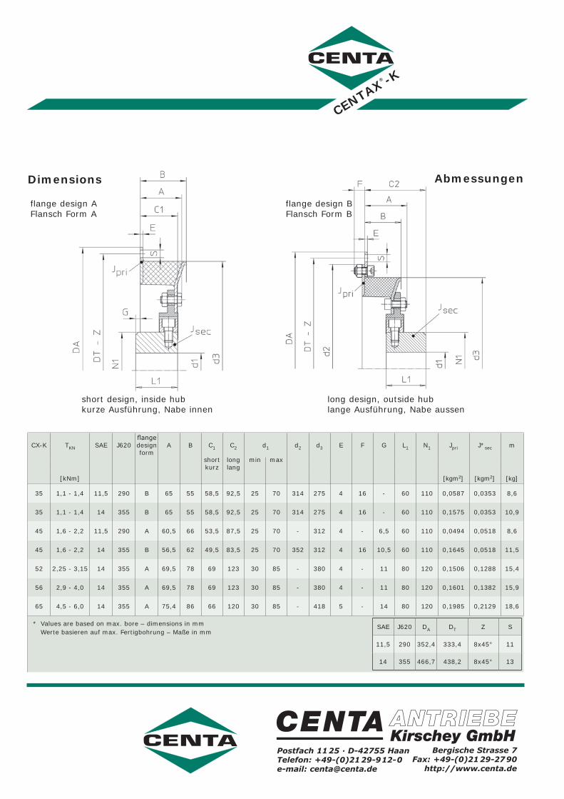
Dimensions
short design, inside hubkurze Ausführung, Nabe innen
flange design AFlansch Form A
long design, outside hublange Ausführung, Nabe aussen
flange design BFlansch Form B
Abmessungen
CX-K TKN SAE J620flangedesign form
A B C1 C2 d1 d2 d3 E F G L1 N1 Jpri J*sec m
shortkurz
longlang
min max
[kNm] [kgm2] [kgm2] [kg]
35 1,1 - 1,4 11,5 290 B 65 55 58,5 92,5 25 70 314 275 4 16 - 60 110 0,0587 0,0353 8,6
35 1,1 - 1,4 14 355 B 65 55 58,5 92,5 25 70 314 275 4 16 - 60 110 0,1575 0,0353 10,9
45 1,6 - 2,2 11,5 290 A 60,5 66 53,5 87,5 25 70 - 312 4 - 6,5 60 110 0,0494 0,0518 8,6
45 1,6 - 2,2 14 355 B 56,5 62 49,5 83,5 25 70 352 312 4 16 10,5 60 110 0,1645 0,0518 11,5
52 2,25 - 3,15 14 355 A 69,5 78 69 123 30 85 - 380 4 - 11 80 120 0,1506 0,1288 15,4
56 2,9 - 4,0 14 355 A 69,5 78 69 123 30 85 - 380 4 - 11 80 120 0,1601 0,1382 15,9
65 4,5 - 6,0 14 355 A 75,4 86 66 120 30 85 - 418 5 - 14 80 120 0,1985 0,2129 18,6
* Values are based on max. bore – dimensions in mm Werte basieren auf max. Fertigbohrung – Maße in mm
Postfach 1125 ∙ D-42755 HaanTelefon: +49-(0)2129-912-0e-mail: [email protected]
Bergische Strasse 7Fax: +49-(0)2129-2790
http://www.centa.de
SAE J620 DA DT Z S
11,5 290 352,4 333,4 8x45° 11
14 355 466,7 438,2 8x45° 13