Embed Size (px)
Citation preview

DESCH Clamp and Flange couplings
SK 11 - GB
Torsionally stif f couplings

2
Torsionally stiff couplings
> Clamp couplings DIN 115 > Flange couplings DIN 116 > Clamp couplings 2-piece design > Clamp couplings 1-piece design
Flange couplings DIN 116
Flange couplings are torsionally stiff, particularly sturdy and reliable shaft connections which can withstand jolts and radially or axially acting loads. The connected shafts must be precisely aligned. The flange couplings Form C are equipped with a hollow for axial thrust washers according to DIN 28135. (Applied, for example, with vertical agitator shafts). Axial thrust washers are not supplied and must be ordered separately. The connection dimensions of the flange couplings are in accordance with DIN 116, the centring of the coupling parts is achieved, however, only by means of fitting bolts. Normal design with feather key groove according to DIN 6885/1. Key slot according to DIN 6886 or DIN 6887 on request. In the case of shaft connections with different shaft diameters the coupling size assigned to the largest shaft diameter is used (reducing coupling).
> Horizontal arrangement: Form A > Vertical arrangement: Form C > Material: Normal design EN-GJL according to DIN EN 1561. On request in steel up to size 100 and in cast steel from size 110
Clamp couplings DIN 115
Clamp couplings are torsionally stiff and reliable shaft connections which can withstand jolts and radially or axially acting loads. The connected shafts must be precisely aligned. With the two shells which are bolted together the couplings are very easy to assembly and are therefore ideally suitable for shafts connected in series (e. g. transmission shafts). When connecting shafts with different diameters we recommend that the thicker shaft end be offset on the diameter of the thinner one. If this is not possible the model with offset hole corresponding to the larger shaft diameter is used (Form B). Clamp couplings can also be supplied with a protective jacket of sheet
steel (Form AS; BS or CS). All clamp couplings have feather key groove according to DIN 6885/1.
> Horizontal arrangement: Form A for shaft ends with same diameters Form B for shaft ends with different diameters > Vertical arrangement: Form A with suspension key according to DIN 28134 Form C with ring inserts according to DIN 115 Sheet 2 > Material: Normal design EN-GJL according to DIN EN 1561. GS-45 on request
Please note:For shaft connections with rigid couplings the shafts must be precisely aligned. In order to avoid any excessive bending load on the coupling bearing must be mounted on both sides of the coupling where long shafts or high rotational speeds are involved.

3
> Material, design: Steel 1.0718, blank ; Stainless steel 1.4305, blank
Steel / Stainless steel
Clamp coupling 1-piece design
Clamp coupling 2-piece design
Abmessung in mmGröße
D1Nennmoment
NmD4 L R
CDIN 912-12.9
Gewichtca. kg
10 100 29 45 32,7 M4 x 12 0,1912 100 29 45 32,7 M4 x 12 0,1814 190 34 50 39,1 M5 x 16 0,2715 190 34 50 39,1 M5 x 16 0,2716 190 34 50 39,1 M5 x 16 0,2619 300 42 65 48,2 M6 x 18 0,5220 350 42 65 48,2 M6 x 18 0,5225 390 45 75 50,8 M6 x 18 0,6230 475 53 83 58,1 M6 x 18 0,92
> Wear- and maintenance-free.
Max. rotation speed: 4000 rpm
Temperature range : -40°C to +175°C
On request: Other dimensions, design with keyway according to DIN 6885.
> Clamp collars surround the shaft with an even distribution of the clamping force and transmit high torques torsionally stiff and free of backlash. Wear- and maintenance-free! This leads to an dimensionally accurate fit and very strong holding forces without damaging the shaft. Shaft tolerances should be within h11. Dimensions and other designs on request.
Clamp collars 1-piece and 2-piece design

4
Clamp couplings DIN 115/ Form A
Size Tolerance2)Torque
Tmax. NmMax. roational speed
nmax. rpmMoments of inertia
kgm2
Weightkg
d3 l
d1 EN-GJL GS EN-GJL GS EN-GJL GS EN-GJL GS mm mm
20 V 7 25 63 1700 1700 0,00093 0,0010 1,9 2,1 85 100
25 V 7 40 100 1500 1500 0,0034 0,0037 4,5 4,9 100 130
30 V 7 60 160 1500 1500 0,0034 0,0036 4,2 4,5 100 130
35 V 7 80 200 1420 1420 0,0066 0,0071 6,5 7,0 110 160
40 V 7 100 250 1420 1420 0,0065 0,0070 6,2 6,7 110 160
45 V 7 125 315 1350 1350 0,011 0,012 8,5 9,2 120 190
50 V 7 150 400 1300 1300 0,014 0,016 9,0 9,7 130 190
55 U 7 500 1600 1200 1200 0,026 0,028 13 14 150 220
60 U 7 850 1800 1200 1200 0,025 0,027 12,5 13,5 150 220
65 U 7 1250 2000 1120 1120 0,051 0,055 18,5 20 170 250
70 U 7 1700 2240 1120 1120 0,050 0,054 17 18 170 250
751) U 7 2000 3150 1060 1060 0,107 0,116 28 30 190 280
80 U 7 2500 3550 1060 1060 0,106 0,114 27 29 190 280
90 U 7 3800 5000 1000 1000 0,203 0,219 41 44 215 310
100 U 7 5400 8000 920 920 0,399 0,431 63 68 250 350
110 U 7 7500 10000 920 920 0,467 0,505 70 76 250 390
120 U 7 11000 16000 870 870 0,771 0,832 96 104 275 430
125 U 7 11000 16000 870 870 0,759 0,820 93 100 275 430
140 U 7 15000 22400 800 800 1,63 1,76 160 173 325 490
160 U 7 23000 31500 750 750 2,84 3,07 255 275 365 560
180 U 7 32000 40000 690 690 5,42 5,86 320 346 420 630
200 U 7 40000 56000 630 630 12,02 12,98 550 594 500 700
2201) U 7 50000 80000 580 580 30,78 33,24 840 907 540 770
> 1) Not included in DIN 115 2) Hole tolerance field for shaft tolerance ISO h9

5
Clamp couplings DIN 115/ Form A
Size Hexagon-head fitting bolts to DIN EN ISO 4014Feather key length
Suspension key axial load max. kN
d1 d6 l2 Anzahl
20 M 10 x 30 4 - -
25 M 12 x 40 4 - 5
30 M 12 x 40 4 - 5
35 M 12 x 50 6 - 8
40 M 12 x 50 6 - 12
45 M 12 x 50 6 - 16
50 M 12 x 50 6 - 16
55 M 16 x 55 6 100 20
60 M 16 x 55 6 100 24
65 M 16 x 55 6 100 24
70 M 16 x 55 6 110 30
751) M 16 x 60 8 125 37
80 M 16 x 75 8 125 37
90 M 16 x 90 8 140 42
100 M 20 x 90 8 160 55
110 M 20 x 90 8 160 55
120 M 24 x 90 10 200 70
125 M 24 x 90 10 200 70
140 M 27 x 110 10 200 90
160 M 27 x110 12 250 110
180 M 27 x 130 12 280 -
200 M 30 x 140 12 320 -
2201) M 36 x 150 12 360 -
> 1) Not included in DIN 115
6
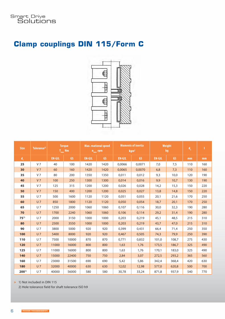
Clamp couplings DIN 115/Form C
> 1) Not included in DIN 115 2) Hole tolerance field for shaft tolerance ISO h9
Size Tolerance2)Torque
Tmax. NmMax. roational speed
nmax. rpmMoments of inertia
kgm2
Weightkg
d3 l
d1 EN-GJL GS EN-GJL GS EN-GJL GS EN-GJL GS mm mm
25 V 7 40 100 1420 1420 0,0066 0,0071 7,0 7,5 110 160
30 V 7 60 160 1420 1420 0,0065 0,0070 6,8 7,3 110 160
35 V 7 80 200 1350 1350 0,011 0,012 9,3 10,0 120 190
40 V 7 100 250 1300 1300 0,014 0,016 9,9 10,7 130 190
45 V 7 125 315 1200 1200 0,026 0,028 14,2 15,3 150 220
50 V 7 150 400 1200 1200 0,025 0,027 13,8 14,8 150 220
55 U 7 500 1600 1120 1120 0,051 0,055 20,1 21,6 170 250
60 U 7 850 1800 1120 1120 0,050 0,054 18,7 20,1 170 250
65 U 7 1250 2000 1060 1060 0,107 0,116 30,0 32,3 190 280
70 U 7 1700 2240 1060 1060 0,106 0,114 29,2 31,4 190 280
751) U 7 2000 3150 1000 1000 0,203 0,219 45,1 48,5 215 310
80 U 7 2500 3550 1000 1000 0,203 0,219 43,7 47,0 215 310
90 U 7 3800 5000 920 920 0,399 0,431 66,4 71,4 250 350
100 U 7 5400 8000 920 920 0,467 0,505 74,3 79,9 250 390
110 U 7 7500 10000 870 870 0,771 0,832 101,0 108,7 275 430
120 U 7 11000 16000 800 800 1,63 1,76 173,5 186,7 325 490
125 U 7 11000 16000 800 800 1,63 1,76 170,1 183,0 325 490
140 U 7 15000 22400 750 750 2,84 3,07 272,5 293,2 365 560
160 U 7 23000 31500 690 690 5,42 5,86 342,4 368,4 420 630
180 U 7 32000 40000 630 630 12,02 12,98 577,0 620,8 500 700
2001) U 7 40000 56000 580 580 30,78 33,24 871,8 937,9 540 770

7
Clamp couplings DIN 115/Form C
> 1) Not included in DIN 115
Size Hexagon-head fitting bolts to DIN EN ISO 4014Feather key length
Maximum lateral load on insert ring
kNd1 d6 l2 Anzahl
25 M 12 x 50 6 56 12
30 M 12 x 50 6 56 17
35 M 12 x 50 6 70 23
40 M 12 x 50 6 70 30
45 M 16 x 55 6 80 36
50 M 16 x 55 6 80 45
55 M 16 x 55 6 90 53
60 M 16 x 55 6 90 62
65 M 16 x 60 8 100 72
70 M 16 x 60 8 100 82
751) M 20 x 75 8 110 92
80 M 20 x 75 8 110 105
90 M 20 x 90 8 125 135
100 M 24 x 90 8 140 165
110 M 24 x 90 10 160 200
120 M 27 x 110 10 180 250
125 M 27 x 110 10 180 250
140 M 27 x 110 12 200 310
160 M 27 x 130 12 220 400
180 M 30 x 140 12 250 500
2001) M 36 x 150 12 280 600

8
> 1) Grooves according to DIN 6685/1; tolerance zone JS9 2) Tolerance of hub length: L3 ≦ 120: +0,3 and L3 > 120: +0,5 respectively
3) Bevel F x 45°
Flange couplings DIN 116
Size D2 D3 D4 D5
D6
(H7)K L1 L2 L3
2) L4 F3) T1
Hexagon-head fitting bolts to DIN 609
D11) mm mm mm mm mm mm mm mm mm mm mm mm D7 L6 Number
25 58 125 40 45 11 90 101 117 50 16 1 8,5 M 10 45 3
30 58 125 40 45 11 90 101 117 50 16 1 8,5 M 10 45 3
35 72 140 50 55 11 100 121 141 60 16 1 10,5 M 10 45 3
40 72 140 50 55 11 100 121 141 60 16 1 10,5 M 10 45 3
45 95 160 60 65 11 125 141 169 70 18 1 14,5 M 10 50 3
50 95 160 60 65 11 125 141 169 70 18 1,6 14,5 M 10 50 3
55 110 180 70 75 13 140 171 203 85 18 1,6 16,5 M 12 50 4
60 110 180 70 75 13 140 171 203 85 18 1,6 16,5 M 12 50 4
70 130 200 80 85 13 160 201 233 100 23 1,6 16,5 M 12 60 6
80 145 224 90 95 13 180 221 261 110 23 1,6 20,5 M 12 60 8
90 164 250 100 105 17 200 241 281 120 30 2,5 20,5 M 16 80 8
100 180 280 110 120 17 224 261 301 130 30 2,5 20,5 M 16 80 8
110 200 300 120 130 17 250 281 329 140 33 2,5 24,5 M 16 85 8
120 225 335 135 145 17 280 311 359 155 33 2,5 24,5 M 16 85 10
125 225 335 135 145 17 280 311 359 155 33 4 24,5 M 16 85 10
140 250 375 150 160 21 310 341 397 170 40 4 28,5 M 20 100 10

9
Technical data
SizeTorque Max. roational speed
Moments of inertia3) Form A
Weight3) Form A
Moments of inertia3) Form C
Weight3)
Form C
Tmax. Nm nmax. rpm kgm2 kg kgm2 kg
D14) EN-GJL1) GS2)5) EN-GJL GS5) EN-GJL GS5) EN-GJL GS5) EN-GJL GS5) EN-GJL GS5)
25 46,2 69 4600 6850 0,0062 0,0067 3,9 4,2 0,0063 0,0068 4,0 4,330 87,5 131 4600 6850 0,0062 0,0067 3,7 4,0 0,0062 0,0067 3,8 4,135 150 225 4100 6150 0,0105 0,0113 5,4 5,8 0,0107 0,0116 5,7 6,140 236 354 4100 6150 0,0104 0,0112 5,2 5,5 0,0106 0,0115 5,4 5,845 355 533 3600 5350 0,023 0,025 9,1 10,0 0,024 0,026 9,8 10,650 515 773 3600 5350 0,023 0,024 8,7 9,4 0,024 0,026 9,5 10,255 730 1095 3200 4750 0,041 0,044 13,1 14,2 0,043 0,047 14,3 15,560 975 1463 3200 4750 0,040 0,043 12,6 13,6 0,043 0,046 13,7 14,870 1700 2550 2850 4300 0,082 0,088 20,0 21,6 0,087 0,094 21,8 23,580 2650 3975 2550 3850 0,134 0,144 26,4 28,5 0,144 0,155 29,1 31,490 4120 6180 2300 3450 0,257 0,276 38,7 41,8 0,274 0,295 42,3 45,7
100 5800 8700 2050 3050 0,404 0,435 49,8 53,7 0,428 0,461 53,8 58,2110 8250 12375 1900 2850 0,608 0,652 64,1 68,9 0,652 0,699 70,4 75,7120 11200 16800 1700 2550 1,011 1,085 88,2 94,7 1,084 1,163 96,3 103,4125 12800 19200 1700 2550 1,003 1,076 86,0 92,4 1,075 1,154 102,1 109,7140 19000 28500 1550 2300 1,81 1,93 121 130 1,93 2,07 133 142
> 1) Max. torque based on DIN 116 Hole tolerance zone: Form A: ISO H7 – for shaft tolerance ISO h9 Form C: ISO N7 – for shaft tolerance ISO k6 and m6 respectively Other hole tolerances can be agreed when ordering.
2) Max. torques (for hole D1) with allowable load on the feather key and with average overdimension of the following tolerance zones: For D1 50: ISO N7 – for shaft tolerance ISO k6 For D1 50: ISO N7 – for shaft tolerance ISO m6
3) Figures for moments of mass inertia and weights for hole D1 (in the case of Form C without axial thrust washer).4) Couplings for D1 = 260 to 500 mm are not included in DIN 116.5) Couplings up to size 100 of steel
Form C

10
Flange couplings DIN 116
Size D2 D3 D4 D5
D6
H7K L1 L2 L3
2) L4 F3) T1
Hexagon-head fitting bolts to DIN 609
D11) mm mm mm mm mm mm mm mm mm mm mm mm D7 L6 Number
160 290 425 240 180 25 350 401 457 200 40 4 28,5 M 24 110 10
180 325 450 265 212 25 380 451 507 225 45 4 28,5 M 24 120 12
200 360 500 290 232 25 420 501 557 250 45 6 28,5 M 24 120 16
220 400 560 310 252 32 470 541 597 270 52 6 28,5 M 30 140 14
250 450 630 390 282 32 540 601 657 300 52 6 28,8 M 30 140 16
260 500 710 420 302 32 600 681 741 340 55 6 30,5 M 30 150 16
280 500 710 420 322 32 600 681 741 340 55 6 30,5 M 30 150 16
300 560 750 460 352 38 640 761 831 380 62 10 35,5 M 36 170 16
320 560 750 460 372 38 640 761 831 380 62 10 35,5 M 36 170 16
340 650 900 520 392 44 760 881 961 440 70 10 40,5 M 42 190 14
360 650 900 520 412 44 760 881 961 440 70 10 40,5 M 42 190 14
380 720 1000 600 442 44 850 1001 1091 500 70 10 45,5 M 42 190 16
400 720 1000 600 462 44 850 1001 1091 500 70 10 45,5 M 42 190 16
420 800 1060 650 482 50 920 1161 1251 580 80 10 45,5 M 48 220 16
450 800 1060 650 512 50 920 1161 1251 580 80 10 45,5 M 48 220 16
460 900 1180 800 532 50 1030 1321 1421 660 90 10 50,5 M 48 240 20
500 900 1180 800 572 50 1030 1321 1421 660 90 16 50,5 M 48 240 20
> 1) Grooves according to DIN 6685/1; tolerance zone JS9 2) Tolerance of hub length: L3 ≦ 120: +0,3 and L3 > 120: +0,5 respectively
3) Bevel F x 45°
Form A Form C

11
SizeTorque Max. roational speed
Moments of inertia3) Form A
Weight3) Form A
Moments of inertia3) Form C
Weight3)
Form C
Tmax. Nm nmax. rpm kgm2 kg kgm2 kg
D14) EN-GJL1) GS2)5) EN-GJL GS5) EN-GJL GS5) EN-GJL GS5) EN-GJL GS5) EN-GJL GS5)
160 30700 46050 1350 2000 3,39 3,63 181 194 3,63 3,89 197 212180 45000 67500 1250 1900 5,30 5,68 242 259 5,67 6,07 261 280200 61500 92250 1150 1700 8,58 9,19 322 346 9,14 9,79 347 372220 82500 123750 1000 1550 14,87 15,92 444 476 16,00 17,14 485 521250 118000 177000 900 1350 25,29 27,09 605 649 26,69 28,59 644 692260 136000 204000 800 1200 44,09 47,28 877 942 46,42 49,79 932 1001280 170000 255000 800 1200 43,32 46,46 835 897 45,55 48,85 886 951300 206000 309000 750 1150 70,10 75,14 1163 1248 74,26 79,61 1239 1330320 250000 375000 750 1150 68,81 73,74 1109 1191 72,77 78,01 1179 1266340 300000 450000 650 950 155,03 166,24 1874 2013 163,89 175,77 1997 2146360 355000 532500 650 950 152,88 163,93 1804 1937 161,43 173,13 1920 2062380 425000 637500 550 850 255,02 273,58 2545 2733 269,85 289,55 2711 2913400 487000 730500 550 850 251,63 269,94 2457 2639 265,99 285,39 2613 2807420 560000 840000 550 800 420,01 450,49 3552 3814 442,88 475,09 3762 4040450 710000 1065000 550 800 411,84 441,69 3378 3628 433,75 465,27 3574 3838460 750000 1125000 500 750 755,07 810,06 5156 5538 796,31 854,42 5458 5864500 950000 1425000 500 750 738,28 792,00 4866 5226 777,58 834,27 5142 5524
Technical data
> 1) Max. torque based on DIN 116 Hole tolerance zone: Form A: ISO H7 – for shaft tolerance ISO h9 Form C: ISO N7 – for shaft tolerance ISO k6 and m6 respectively Other hole tolerances can be agreed when ordering.
2) Max. torques (for hole D1) with allowable load on the feather key and with average overdimension of the following tolerance zones: For D1 ≦ 50: ISO N7 – for shaft tolerance ISO k6 For D1 ≧ 50: ISO N7 – for shaft tolerance ISO m6
3) Figures for moments of mass inertia and weights for hole D1 (in the case of Form C without axial thrust washer).4) Couplings for D1 = 260 to 500 mm are not included in DIN 116.5) Couplings up to size 100 of steel
Form C

DESCH DPC GmbH & Co. KGPostbox 14 4059753 Arnsberg/GermanyKleinbahnstraße 2159759 Arnsberg/GermanyT +49 2932 300-0F +49 2932 300-830I www.desch.deE [email protected]
Postbox14 40 | 59753 Arnsberg/GermanyKleinbahnstraße 21 | 59759 Arnsberg/GermanyT +49 2932 300-0 | F +49 2932 300-899I www.desch.de | E [email protected]
DESCH Canada Ltd.240 Shearson Crescent Cambridge, Ontario Canada N 1T 1J6T +1800 2631866 +1519 6214560 F +1519 6231169I www.desch.de E [email protected]
DESCH Italia Drive Technology Ufficio di rappresentanza in Italia Via Cavriana, 3 20134 Milano/ItalyT +3902 7391280 F +3902 7391281I www.desch.deE [email protected]
DESCH China Machinery Sales (Shanghai) Ltd. Building Nr. 3No. 388 Minshen Road,Songjiang Industrial Zone201612 Shanghai/ChinaT +86 21 6126-8061F +86 21 57655155I www.desch.deE [email protected]
DESCH Antriebstechnik GmbH & Co. KGTe
chnic
al
changes
reserv
ed
© 2
011
D
ES
CH
Antr
iebste
chnik
Gm
bH
& C
o.
KG
S
K 1
1 -
GB