Embed Size (px)
Citation preview


CE EMC TEST REPORT Report No. : EC482159
SPORTON International Inc.
TEL : 886-3-327-3456
FAX : 886-3-327-0973
CE EMC TEST REPORT
according to
European Standard EN 55022:2010/AC:2011 Class B, EN 61000-3-2:2006/A1:2009 and /A2:2009, EN 61000-3-3:2008 and
EN 55024:2010 ( IEC 61000-4-2 Edition 2.0 2008-12 IEC 61000-4-3 Edition 3.2 2010-04, IEC 61000-4-4 Edition 3.0 2012-05 IEC 61000-4-5 Edition 2.0 2005-11, IEC 61000-4-6 Edition 3.0 2008-10
IEC 61000-4-8 Edition 2.0 2009-09, IEC 61000-4-11 Edition 2.0 2004-03 )
Equipment : IPC Bare Bone System
Model No. : JNF9QUXX-YYYY (X & Y Stands for "0~9", "A~Z") HBJC5WWF9QUXX-YYYY-ZZ (W, X, Y & Z Stands for "0~9", "A~Z")
Applicant : Jetway Information Co., Ltd. 9F., No. 207, Sec. 3, Beixin Rd., Xindian Dist., New Taipei City 231, Taiwan (R.O.C.)
Statement The test result refers exclusively to the test presented test model / sample.
Without written approval of SPORTON International Inc., the test report shall not be reproduced except in full.
This test report is only applicable to European Community.
SPORTON International Inc. No. 52, Hwa Ya 1st Rd., Hwa Ya Technology Park, Kwei-Shan Hsiang, Tao Yuan Hsien, Taiwan, R.O.C.

CE EMC TEST REPORT Report No. : EC482159
SPORTON International Inc. Page Number : 1 of 83
TEL : 886-3-327-3456 Issued Date : Sep. 29, 2014 FAX : 886-3-327-0973 Report Version : 01
Table of Contents
History of this test report .................................................................................................................................... 4
CERTIFICATE OF COMPLIANCE ........................................................................................................................ 5
1. General Description of Equipment under Test ............................................................................................. 6 1.1. Applicant .......................................................................................................................................................................................... 6 1.2. Manufacturer ................................................................................................................................................................................... 6 1.3. Basic Description of Equipment under Test .................................................................................................................................... 6 1.4. Feature of Equipment under Test ................................................................................................................................................... 6
2. Test Configuration of Equipment under Test ............................................................................................... 7 2.1. Test Manner .................................................................................................................................................................................... 7 2.2. Description of Test System ............................................................................................................................................................. 8 2.3. Connection Diagram for AC Powerline Conducted and Radiated Emission ................................................................................. 10
3. Test Software ................................................................................................................................................. 11
4. General Information of Test .......................................................................................................................... 12 4.1. Test Facility ................................................................................................................................................................................... 12 4.2. Test Voltage .................................................................................................................................................................................. 12 4.3. Measurement Procedure ............................................................................................................................................................... 12 4.4. Test in Compliance with ................................................................................................................................................................ 12 4.5. Frequency Range Investigated ..................................................................................................................................................... 13 4.6. Test Distance ................................................................................................................................................................................ 13
5. Conducted Emissions Measurement .......................................................................................................... 14 5.1. Limits for conducted disturbance at mains terminals and telecommunication ports ..................................................................... 14 5.2. Test Procedures ............................................................................................................................................................................ 15 5.3. Typical Test Setup Layout of AC Powerline Conducted Emissions .............................................................................................. 16 5.4. Typical Test Setup Layout of Disturbance at Telecommunication Ports ....................................................................................... 17 5.5. Test Result of AC Powerline Conducted Emission ....................................................................................................................... 18 5.6. Photographs of Conducted Power line Test Configuration ........................................................................................................... 20 5.7. Test Result of Disturbance at Telecommunication Ports .............................................................................................................. 21 5.8. Photographs of Telecommunication Ports Test Configuration ...................................................................................................... 24
6. Radiated Emission Measurement ................................................................................................................ 25 6.1. Limits for radiated disturbance ...................................................................................................................................................... 25 6.2. Test Procedures ............................................................................................................................................................................ 26 6.3. Typical Test Setup Layout of Radiated Emissions ........................................................................................................................ 27 6.4. Test Result of Radiated Emission for Below 1GHz ....................................................................................................................... 28 6.5. Photographs of Radiated Emission (Below 1GHz) Test Configuration ......................................................................................... 32 6.6. Test Result of Radiated Emission for Above 1GHz ...................................................................................................................... 33 6.7. Photographs of Radiated Emission (From 1GHz to 6GHz) Test Configuration ............................................................................ 35
7. Harmonic Current Emissions Measurement ............................................................................................... 36 7.1. Standard ........................................................................................................................................................................................ 36 7.2. Test Procedure .............................................................................................................................................................................. 36 7.3. Test Equipment Settings ............................................................................................................................................................... 36 7.4. Typical Test Setup Layout of Harmonic Current Emissions .......................................................................................................... 36 7.5. Test Result of Harmonic Current Emissions ................................................................................................................................. 37
8. Voltage Fluctuations and Flicker Measurement ......................................................................................... 38 8.1. Standard ........................................................................................................................................................................................ 38 8.2. Test Procedure .............................................................................................................................................................................. 38

CE EMC TEST REPORT Report No. : EC482159
SPORTON International Inc. Page Number : 2 of 83
TEL : 886-3-327-3456 Issued Date : Sep. 29, 2014 FAX : 886-3-327-0973 Report Version : 01
8.3. Test Equipment Settings ............................................................................................................................................................... 38 8.4. Typical Test Setup Layout of Voltage Fluctuations and Flicker .................................................................................................... 38 8.5. Test Result of Voltage Fluctuation and Flicker .............................................................................................................................. 39 8.6. Photographs of Voltage Fluctuation and Flicker Test ................................................................................................................... 40
9. Electrostatic Discharge Immunity Measurement (ESD) ............................................................................ 41 9.1. Test Setup ..................................................................................................................................................................................... 42 9.2. Test Setup for Tests Performed in Laboratory .............................................................................................................................. 42 9.3. ESD Test Procedure ..................................................................................................................................................................... 43 9.4. Test Severity Levels ...................................................................................................................................................................... 44 9.5. Test Points .................................................................................................................................................................................... 45 9.6. Photographs of Test Points ........................................................................................................................................................... 46 9.7. Photographs of Electrostatic Discharge Immunity Test ................................................................................................................ 47
10. Radio Frequency Electromagnetic Field Immunity Measurement (RS) ................................................. 48 10.1. Test Record ................................................................................................................................................................................ 49 10.2. Test Setup ................................................................................................................................................................................... 50 10.3. Test Procedure ........................................................................................................................................................................... 50 10.4. Test Severity Levels .................................................................................................................................................................... 51 10.5. Photographs of Radio Frequency Electromagnetic Field Immunity Test .................................................................................... 52
11. Electrical Fast Transient/Burst Immunity Measurement (EFT/BURST) ................................................. 53 11.1. Test Record ................................................................................................................................................................................ 54 11.2. Test setup ................................................................................................................................................................................... 55 11.3. Test on Power Line ..................................................................................................................................................................... 56 11.4. Test on Communication Lines .................................................................................................................................................... 56 11.5. Test Procedure ........................................................................................................................................................................... 56 11.6. Test Severity Levels .................................................................................................................................................................... 57 11.7. Photographs of Electrical Fast Transient/Burst Immunity Test ................................................................................................... 58
12. Surge Immunity Measurement ................................................................................................................... 59 12.1. Test Record ................................................................................................................................................................................ 60 12.2. Test Severity Levels .................................................................................................................................................................... 61 12.3. Test Procedure ........................................................................................................................................................................... 61 12.4. Operating Condition .................................................................................................................................................................... 62 12.5. Photographs of Surge Immunity Test ......................................................................................................................................... 63
13. Conducted Disturbances Induced by Radio-Frequency Field Immunity Measurement (CS) ......... 64 13.1. Test Record ................................................................................................................................................................................ 65 13.2. Test Step for Tested Port ............................................................................................................................................................ 65 13.3. Test Severity Levels .................................................................................................................................................................... 66 13.4. Operating Condition .................................................................................................................................................................... 66 13.5. Test Procedure ........................................................................................................................................................................... 66 13.6. Photographs of CS Immunity Test .............................................................................................................................................. 67
14. Power Frequency Magnetic Field immunity Measurement (PFMF) ........................................................ 68 14.1. Test Record ................................................................................................................................................................................ 68 14.2. Test Setup ................................................................................................................................................................................... 68 14.3. Photographs of Power Frequency Magnetic Field Immunity Tests ............................................................................................. 69
15. Voltage Dips and Voltage Interruptions Immunity Measurement (DIP) ................................................. 70 15.1. Test Record of Voltage Interruption ............................................................................................................................................ 71 15.2. Test Record of Voltage Dips ....................................................................................................................................................... 71 15.3. Testing Requirement and Procedure .......................................................................................................................................... 71 15.4. Test Conditions ........................................................................................................................................................................... 71 15.5. Operating Condition .................................................................................................................................................................... 71

CE EMC TEST REPORT Report No. : EC482159
SPORTON International Inc. Page Number : 3 of 83
TEL : 886-3-327-3456 Issued Date : Sep. 29, 2014 FAX : 886-3-327-0973 Report Version : 01
15.6. Photographs of Voltage Dips and Voltage Interruption Immunity Tests ..................................................................................... 72
16. List of Measuring Equipment Used ........................................................................................................... 73
17. Uncertainty of Test Site .............................................................................................................................. 77
Appendix A. Photographs of EUT ........................................................................................................ A1 ~ A11

CE EMC TEST REPORT Report No. : EC482159
SPORTON International Inc. Page Number : 4 of 83
TEL : 886-3-327-3456 Issued Date : Sep. 29, 2014 FAX : 886-3-327-0973 Report Version : 01
History of this test report
Original Report Issue Date: Sep. 29, 2014
No additional attachment.
Additional attachments were issued as in the following record:
Report No. Version Issue Date Description
EC431105-01


CE EMC TEST REPORT Report No. : EC482159
SPORTON International Inc. Page Number : 6 of 83
TEL : 886-3-327-3456 Issued Date : Sep. 29, 2014 FAX : 886-3-327-0973 Report Version : 01
1. General Description of Equipment under Test
1.1. Applicant
Jetway Information Co., Ltd.
9F., No. 207, Sec. 3, Beixin Rd., Xindian Dist., New Taipei City 231, Taiwan (R.O.C.)
1.2. Manufacturer
Same as 1.1
1.3. Basic Description of Equipment under Test
Equipment : IPC Bare Bone System
Model No. :JNF9QUXX-YYYY (X & Y Stands for "0~9", "A~Z")
HBJC5WWF9QUXX-YYYY-ZZ (W, X, Y & Z Stands for "0~9", "A~Z") Power Supply Type : From Adapter (switching)
AC Power Cord : Non-Shielded, 1.85 m, 3 pin
DC Power Cord : B-Shielded, 1.8 m
1.4. Feature of Equipment under Test
Please refer to user manual.

CE EMC TEST REPORT Report No. : EC482159
SPORTON International Inc. Page Number : 7 of 83
TEL : 886-3-327-3456 Issued Date : Sep. 29, 2014 FAX : 886-3-327-0973 Report Version : 01
2. Test Configuration of Equipment under Test
2.1. Test Manner
a. During testing, the interface cables and equipment positions were varied according to European
Standard EN 55022 .
b. The complete test system included LCD Monitor*2, Keyboard*1, Mouse*1, Modem*2, Printer*1,
Headset*1, USB 3.0 Flash Disk*1, Remote workstation: PC*2, LCD Monitor*2, Keyboard*2, Mouse*2
and EUT for EMI test.
c. The complete test system included Monitor*1, Keyboard*1, Mouse*1, Modem*2, Headset*1, USB 3.0
Flash Disk*1, Remote workstation: Notebook*2 and EUT for EMS test.
d. The equipment under test were performed the following test modes:
Test Items Description of test modes
AC Conducted
Emission
Mode 1. R/W,DVI+VGA:1920*1200,LAN:1G*2
Mode 2. R/W,HDMI:1920*1080,LAN:1G*2
The following test mode was referred to pretest worst case “Mode 2” for final test.
ISN
Mode 2(a). LAN 1 : 1Gbps
Mode 2(b). LAN 2 : 1Gbps
Mode 2(c). LAN 1 : 100Mbps
Mode 2(d). LAN 1 : 10Mbps
The following test mode was referred to pretest worst case “Mode 2(a),(c),(d)” for
final test.
Radiated
Emissions
Below 1GHz
Mode 1. R/W,DVI+VGA:1920*1200,LAN:1G*2
Mode 2. R/W,HDMI:1920*1080,LAN:1G*2
The following test mode was referred to pretest worst case “Mode 2” for final test.
Radiated
Emissions
Above 1GHz
Mode 1. R/W,DVI+VGA:1920*1200,LAN:1G*2
Flicker
Emissions
Mode 1. R/W,DVI+VGA:1920*1200,LAN:1G*2
Mode 2. R/W,HDMI:1920*1080,LAN:1G*2
EMS Mode 1. R/W,DVI+VGA:1920*1200,LAN:1G*2
Mode 2. R/W,HDMI:1920*1080,LAN:1G*2
e. Frequency range investigated: Conduction 150 kHz to 30 MHz, Radiation 30 MHz to 6,000 MHz.
f. Frequency range investigated immunity test: CS 150 kHz to 80 MHz, RS 80 MHz to 1,000 MHz.

CE EMC TEST REPORT Report No. : EC482159
SPORTON International Inc. Page Number : 8 of 83
TEL : 886-3-327-3456 Issued Date : Sep. 29, 2014 FAX : 886-3-327-0973 Report Version : 01
2.2. Description of Test System
<For conducted emission and Radiated emission below 1GHz >
No. Peripheral Manufacturer Model Number Cable / Spec. Description
For Local
1 LCD MONITOR”24” DELL U2410F D-sub Cable, D-Shielded, 1.8m
HDMI Cable, D-Shielded, 1.5m
2 LCD MONITOR”24” DELL U2410F DVI Cable, D-Shielded, 1.8m
3 Keyboard Lenovo KU-0225 USB Cable, AL-F-Shielded, 1.8m
4 MOUSE Lenovo M-U0025-O USB Cable, AL-F-Shielded, 1.8m
5 Modem *2 ACEEX DM1414 RS-232 Cable, D-Shielded, 1.15m
6 Printer XEROX PHASER3121 USB Cable, D-Shielded, 1.8m
7 Headset i-Acon HOH-323-BK Audio Cable, Non-Shielded, 2.0m
8 USB 3.0 FLASH DISK PQI U273V -
For Remote
9 PC *2 Lenovo C61 -
10 LCD MONITOR”19”*2 DELL E198WFPF D-SUB Cable, D-Shielded, 1.8m
11 Keyboard *2 Lenovo KU-0225 USB Cable, AL-F-Shielded, 1.8m
12 MOUSE *2 Lenovo M-U0025-O USB Cable, AL-F-Shielded, 1.8m
<Radiated emission above 1GHz >
No. Peripheral Manufacturer Model Number Cable / Spec. Description
For Local
1 LCD MONITOR”24” DELL 2408WFPB D-sub Cable, D-Shielded, 1.8m
HDMI Cable, D-Shielded, 1.5m
2 LCD MONITOR”24” DELL U2410f DVI Cable, D-Shielded, 1.8m
3 Keyboard DELL SK-8175 USB Cable, AL-F-Shielded, 1.8m
4 MOUSE DELL MOC5UO USB Cable, AL-F-Shielded, 1.8m
5 Modem *2 ACEEX DM1414 RS-232 Cable, D-Shielded, 1.15m
6 Printer EPSON C61 USB Cable, D-Shielded, 1.8m
7 Headset INTOPIC JAZZ-368 Audio Cable, Non-Shielded, 2.0m
8 USB 3.0 FLASH DISK PHILIPS FM08FD75B -
For Remote
9 PC *2 HP DC7700 -
10 LCD MONITOR”24”*2 DELL 2408WFPB D-SUB Cable, D-Shielded, 1.8m
11 Keyboard *2 Microsoft 1366 USB Cable, AL-F-Shielded, 1.8m
12 MOUSE *2 Microsoft 1113 USB Cable, AL-F-Shielded, 1.8m

CE EMC TEST REPORT Report No. : EC482159
SPORTON International Inc. Page Number : 9 of 83
TEL : 886-3-327-3456 Issued Date : Sep. 29, 2014 FAX : 886-3-327-0973 Report Version : 01
< EMS >
No. Peripheral Manufacturer Model Number Cable / Spec. Description
For Local
1 Monitor DELL 2408WFPB
D-sub Cable, D-Shielded, 1.8m
HDMI Cable, D-Shielded, 1.5m
DVI Cable, D-Shielded, 1.8m
2 USB 3.0 FLASH DISK PHILIPS FM08FD75B -
3 Modem *2 ACEEX DM1414 RS-232 Cable, D-Shielded, 1.15m
4 Mouse Microsoft 1366 USB Cable, D-Shielded, 1.85m
5 keyboard Microsoft MSK-1113 USB Cable, D-Shielded, 1.85m
6 Headset INTOPIC SR-MK02 Audio Cable, Non-Shielded,1.8m
For Remote
7 NB HP Pavilion dm1 -
8 NB HP 541 -

CE EMC TEST REPORT Report No. : EC482159
SPORTON International Inc. Page Number : 10 of 83
TEL : 886-3-327-3456 Issued Date : Sep. 29, 2014 FAX : 886-3-327-0973 Report Version : 01
2.3. Connection Diagram for AC Powerline Conducted and Radiated Emission
Test Setup Diagram
1. D-sub Cable was connected from support unit 1 to EUT.
2. HDMI Cable was connected from support unit 1 to EUT.
3. DVI Cable was connected from support unit 2 to EUT.
4. USB Cable was connected from support unit 3 to EUT.
5. USB Cable was connected from support unit 4 to EUT.
6. RS-232 Cable was connected from support unit 5 to EUT.
7. RS-232 Cable was connected from support unit 5 to EUT.
8. USB Cable was connected from support unit 6 to EUT.
9. Audio Cable was connected from support unit 7 to EUT.
10. USB Flash was plugged into EUT.
11. RJ45 Cable was connected from EUT to remote work station.
12. RJ45 Cable was connected from EUT to remote work station.
Note: Above support unit on behalf of the meaning, please refer to section 2.2.

CE EMC TEST REPORT Report No. : EC482159
SPORTON International Inc. Page Number : 11 of 83
TEL : 886-3-327-3456 Issued Date : Sep. 29, 2014 FAX : 886-3-327-0973 Report Version : 01
3. Test Software <EMI>
Conduction & Radiated Test :
One executive program was used as the test software under Win 7.
The programs were executed as follows:
a. EUT conducted “EMI program” to drive peripheral printer and modem.
b. The printer printed “H” patterns out.
c. EUT conducted “WINTHRAX” to do read/write function with USB Flash.
d. EUT conducted “Media player” to play audio signal from headset.
e. EUT conducted “Sound Recorder” to record audio signal from headset.
f. EUT conducted “MyHwin” to send “H” messages to the monitor and the monitor displayed “H” patterns.
g. EUT conducted “PING” to maintain connection with remote PC via LAN.
< ISN >
During testing, the remote PC executed "Tfgen" to do ISN(T8) test (LAN utilization in excess of 10 %) via
RJ45 cable.
< EMS >
One executive program was used as the test software under Win 7.
The programs were executed as follows:
a. The remote notebooks executed "Ping" to maintain connection with the EUT via LAN.
b. EUT conducted “MyHwin” to drive peripheral monitor and to display “H” patterns on the monitor.
c. EUT conducted “WINTHRAX” to do read/write function with USB Flash.
d. EUT conducted “Media player” to play audio signal from headset.

CE EMC TEST REPORT Report No. : EC482159
SPORTON International Inc. Page Number : 12 of 83
TEL : 886-3-327-3456 Issued Date : Sep. 29, 2014 FAX : 886-3-327-0973 Report Version : 01
4. General Information of Test
4.1. Test Facility
<EMI>
Test Site:SPORTON INTERNATIONAL INC.
Test Site Location : No. 3, Lane 238, Kangle St., Neihu Chiu, Taipei 114, Taiwan, R.O.C.
TEL : 886-2-2631-4739
FAX : 886-2-2631-9740
Test Site No. : CO01-NH/OS02-NH
Test Site Location : No. 52, Hwa Ya 1st Rd., Hwa Ya Technology Park, Kwei-Shan Hsiag,
Tao Yuan Hsien, Taiwan, R.O.C.
TEL : 886-3-327-3456
FAX : 886-3-327-0973
Test Site No. : 03CH04-HY
<EMS>
Test Site Location : No. 52, Hwa Ya 1st Rd., Hwa Ya Technology Park, Kwei-Shan Hsiag,
Tao Yuan Hsien, Taiwan, R.O.C.
TEL : 886-3-327-3456
FAX : 886-3-327-0973
4.2. Test Voltage
AC 230V / 50Hz
4.3. Measurement Procedure
EMI Test : European Standard EN 55022 Class B
Harmonics Test : European Standard EN 61000-3-2
Voltage Fluctuations Test : European Standard EN 61000-3-3
EMS Test : European Standard EN 55024
(ESD: IEC 61000-4-2, RS: IEC 61000-4-3, EFT: IEC 61000-4-4, SURGE: IEC 61000-4-5,
CS: IEC 61000-4-6, Power Frequency Magnetic Field: IEC 61000-4-8, DIPS: IEC 61000-4-11)
4.4. Test in Compliance with
EMI Test : European Standard EN 55022 Class B
Harmonics Test : European Standard EN 61000-3-2
Voltage Fluctuations Test : European Standard EN 61000-3-3
EMS Test : European Standard EN 55024
(ESD: IEC 61000-4-2, RS: IEC 61000-4-3, EFT: IEC 61000-4-4, SURGE: IEC 61000-4-5,
CS: IEC 61000-4-6, Power Frequency Magnetic Field: IEC 61000-4-8, DIPS: IEC 61000-4-11)

CE EMC TEST REPORT Report No. : EC482159
SPORTON International Inc. Page Number : 13 of 83
TEL : 886-3-327-3456 Issued Date : Sep. 29, 2014 FAX : 886-3-327-0973 Report Version : 01
4.5. Frequency Range Investigated
a. Conducted emission test: from 150 kHz to 30 MHz
b. Radiated emission test: from 30 MHz to 6,000 MHz
c. Radio frequency electromagnetic field immunity test: 80-1000 MHz
4.6. Test Distance
a. The test distance of radiated emission test from antenna to EUT is 10 M (from 30MHz~1GHz).
b. The test distance of radiated emission test from antenna to EUT is 3 M (from 1GHz~6GHz).
c. The test distance of radio frequency electromagnetic field immunity test from antenna to EUT is 3 M.

CE EMC TEST REPORT Report No. : EC482159
SPORTON International Inc. Page Number : 14 of 83
TEL : 886-3-327-3456 Issued Date : Sep. 29, 2014 FAX : 886-3-327-0973 Report Version : 01
5. Conducted Emissions Measurement
Conducted Emissions were measured from 150 kHz to 30 MHz with a bandwidth of 9 kHz and return leads of
the EUT according to the methods defined in European Standard EN 55022 Clause 9. The EUT was placed
on a nonmetallic stand in a shielded room 0.8 meter above the ground plane as shown in section 6.4. The
interface cables and equipment positioning were varied within limits of reasonable applications to determine
the position producing maximum conducted emissions.
5.1. Limits for conducted disturbance at mains terminals and telecommunication ports
Limits for conducted disturbance at mains terminals
Frequency range
(MHz)
Class A Limits
dB(μV)
Class B Limits
dB(μV)
Quasi-peak Average Quasi-peak Average
0.15 to 0.50 79 66 66 - 56 56 - 46
0.50 to 5 73 60 56 46
5 to 30 73 60 60 50
NOTE: The limits decrease linearly with the logarithm of the frequency in the range 0.15 MHz to 0.5 MHz.
Limits for conducted disturbance at telecommunication ports
Frequency range
(MHz)
Class B
Voltage limits
dB (μV)
Current limits
dB (μA)
Quasi-peak Average Quasi-peak Average
0.15 to 0.50 84 - 74 74 - 64 40 - 30 30 - 20
0.50 to 30 74 64 30 20
NOTE: The limits decrease linearly with the logarithm of the frequency in the range 0.15 MHz to 0.5 MHz.

CE EMC TEST REPORT Report No. : EC482159
SPORTON International Inc. Page Number : 15 of 83
TEL : 886-3-327-3456 Issued Date : Sep. 29, 2014 FAX : 886-3-327-0973 Report Version : 01
5.2. Test Procedures
a. The EUT was warmed up for 15 minutes before testing started.
b. The EUT was placed on a desk 0.8 meter height from the metal ground plane and 0.4 meter from the
conducting wall of the shielding room and it was kept at least 0.8 meter from any other grounded
conducting surface.
c. Connect EUT to the power mains through a line impedance stabilization network (LISN).
d. Connect Telecommunication port to ISN (Impedance Stabilization Network).
e. All the support units are connect to the other LISN.
f. The LISN provides 50 ohm, coupling impedance for the measuring instrument.
g. The CISPR states that a 50 ohm, 50 microhenry LISN should be used.
h. Both sides of AC line were checked for maximum conducted interference.
i. The frequency range from 150 kHz to 30 MHz was searched.
j. Set the test-receiver system to Peak Detect Function and Specified Bandwidth with Maximum Hold
Mode.

CE EMC TEST REPORT Report No. : EC482159
SPORTON International Inc. Page Number : 16 of 83
TEL : 886-3-327-3456 Issued Date : Sep. 29, 2014 FAX : 886-3-327-0973 Report Version : 01
5.3. Typical Test Setup Layout of AC Powerline Conducted Emissions
a. AMN is 80 cm from the EUT and at least 80 cm from other units and other metal planes.
b. EUT is connected to one artificial mains network (AMN).
c. All other units of a system are powered from a second AMN. A multiple outlet strip can be used
for multiple mains cords.
d. Rear of EUT to be flushed with rear of table top.
e. Peripherals shall be placed at a distance of 10 cm from each other and from the controller,
except for the monitor which, if this is an acceptable installation practice, shall be placed directly
on the top of the controller.
f. If cables, which hang closer than 40 cm to the horizontal metal ground plane, cannot be
shortened to appropriate length, the excess shall be folded back and forth forming a bundle 30
cm to 40 cm long.
g. Mains cords and signal cables shall be positioned for their entire lengths, as far as possible, at
40 cm from the vertical reference plane.
h. Cables of hand operated devices, such as keyboards, mice, etc. shall be placed as for normal
usage.
CE EMC TEST REPORT Report No. : EC482159
SPORTON International Inc. Page Number : 17 of 83
TEL : 886-3-327-3456 Issued Date : Sep. 29, 2014 FAX : 886-3-327-0973 Report Version : 01
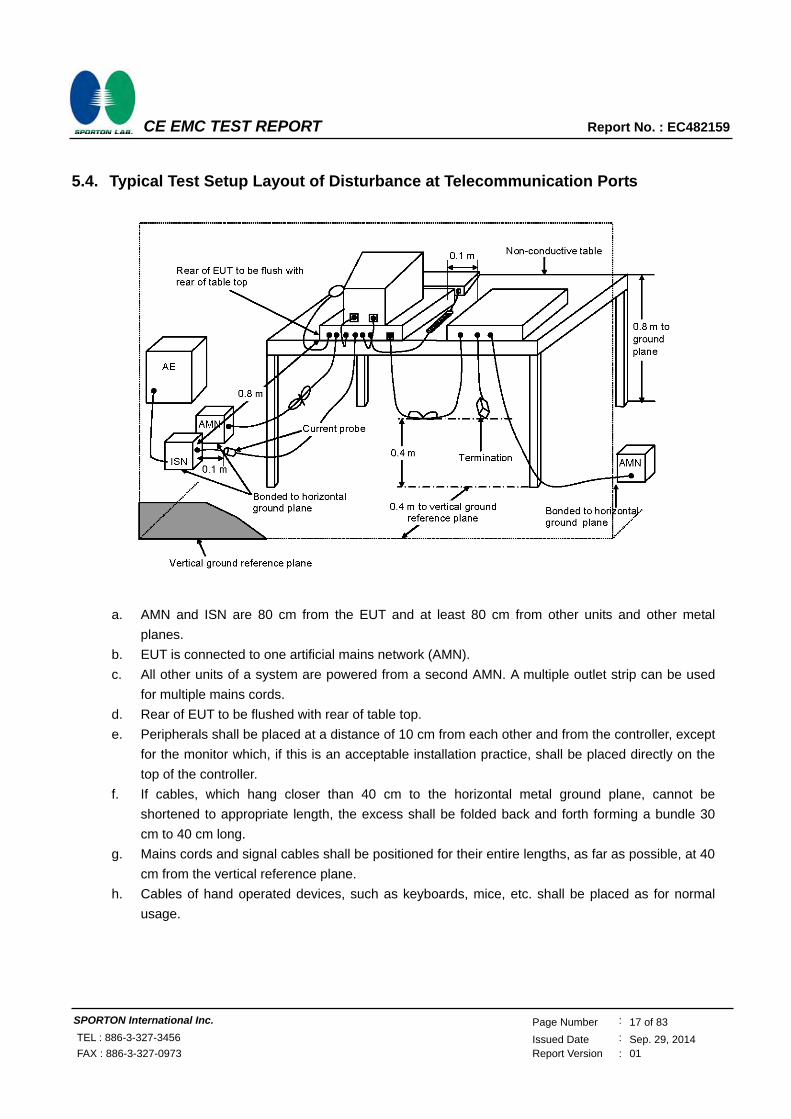
5.4. Typical Test Setup Layout of Disturbance at Telecommunication Ports
a. AMN and ISN are 80 cm from the EUT and at least 80 cm from other units and other metal
planes.
b. EUT is connected to one artificial mains network (AMN).
c. All other units of a system are powered from a second AMN. A multiple outlet strip can be used
for multiple mains cords.
d. Rear of EUT to be flushed with rear of table top.
e. Peripherals shall be placed at a distance of 10 cm from each other and from the controller, except
for the monitor which, if this is an acceptable installation practice, shall be placed directly on the
top of the controller.
f. If cables, which hang closer than 40 cm to the horizontal metal ground plane, cannot be
shortened to appropriate length, the excess shall be folded back and forth forming a bundle 30
cm to 40 cm long.
g. Mains cords and signal cables shall be positioned for their entire lengths, as far as possible, at 40
cm from the vertical reference plane.
h. Cables of hand operated devices, such as keyboards, mice, etc. shall be placed as for normal
usage.

CE EMC TEST REPORT Report No. : EC482159
SPORTON International Inc. Page Number : 18 of 83
TEL : 886-3-327-3456 Issued Date : Sep. 29, 2014 FAX : 886-3-327-0973 Report Version : 01
5.5. Test Result of AC Powerline Conducted Emission
Test Mode Mode 2 Test Site No. CO01-NH
Test Frequency 0.15 MHz ~ 30 MHz Test Engineer Willy
Temperature 27 Relative Humidity 54 %
Note: 1. Corrected Reading (dBV) = LISN Factor + Cable Loss + Read Level = Level
2. All emissions not reported here are more than 10 dB below the prescribed limit.
The test was passed at the minimum margin that marked by the frame in the following data
Line

CE EMC TEST REPORT Report No. : EC482159
SPORTON International Inc. Page Number : 19 of 83
TEL : 886-3-327-3456 Issued Date : Sep. 29, 2014 FAX : 886-3-327-0973 Report Version : 01
Neutral

CE EMC TEST REPORT Report No. : EC482159
SPORTON International Inc. Page Number : 20 of 83
TEL : 886-3-327-3456 Issued Date : Sep. 29, 2014 FAX : 886-3-327-0973 Report Version : 01
5.6. Photographs of Conducted Power line Test Configuration
The photographs show the configuration that generates the maximum emission.
FRONT VIEW
REAR VIEW
CE EMC TEST REPORT Report No. : EC482159
SPORTON International Inc. Page Number : 21 of 83
TEL : 886-3-327-3456 Issued Date : Sep. 29, 2014 FAX : 886-3-327-0973 Report Version : 01
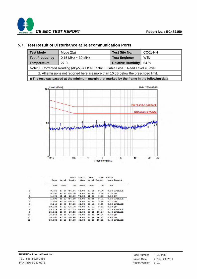
5.7. Test Result of Disturbance at Telecommunication Ports
Test Mode Mode 2(a) Test Site No. CO01-NH
Test Frequency 0.15 MHz ~ 30 MHz Test Engineer Willy
Temperature 27 Relative Humidity 54 %
Note: 1. Corrected Reading (dBV) = LISN Factor + Cable Loss + Read Level = Level
2. All emissions not reported here are more than 10 dB below the prescribed limit.
The test was passed at the minimum margin that marked by the frame in the following data

CE EMC TEST REPORT Report No. : EC482159
SPORTON International Inc. Page Number : 22 of 83
TEL : 886-3-327-3456 Issued Date : Sep. 29, 2014 FAX : 886-3-327-0973 Report Version : 01
Test Mode Mode 2(c) Test Site No. CO01-NH
Test Frequency 0.15 MHz ~ 30 MHz Test Engineer Willy
Temperature 27 Relative Humidity 54 %
Note: 1. Corrected Reading (dBV) = LISN Factor + Cable Loss + Read Level = Level
2. All emissions not reported here are more than 10 dB below the prescribed limit.
The test was passed at the minimum margin that marked by the frame in the following data

CE EMC TEST REPORT Report No. : EC482159
SPORTON International Inc. Page Number : 23 of 83
TEL : 886-3-327-3456 Issued Date : Sep. 29, 2014 FAX : 886-3-327-0973 Report Version : 01
Test Mode Mode 2(d) Test Site No. CO01-NH
Test Frequency 0.15 MHz ~ 30 MHz Test Engineer Willy
Temperature 27 Relative Humidity 54 %
Note: 1. Corrected Reading (dBV) = LISN Factor + Cable Loss + Read Level = Level
2. All emissions not reported here are more than 10 dB below the prescribed limit.
The test was passed at the minimum margin that marked by the frame in the following data

CE EMC TEST REPORT Report No. : EC482159
SPORTON International Inc. Page Number : 24 of 83
TEL : 886-3-327-3456 Issued Date : Sep. 29, 2014 FAX : 886-3-327-0973 Report Version : 01
5.8. Photographs of Telecommunication Ports Test Configuration
The photographs show the configuration that generates the maximum emission.
FRONT VIEW
REAR VIEW

CE EMC TEST REPORT Report No. : EC482159
SPORTON International Inc. Page Number : 25 of 83
TEL : 886-3-327-3456 Issued Date : Sep. 29, 2014 FAX : 886-3-327-0973 Report Version : 01
6. Radiated Emission Measurement
Radiated emissions from 30 MHz to 6,000 MHz were measured with a bandwidth of 120 kHz for 30 MHz to
1,000 MHz and 1 MHz for above 1GHz according to the methods defines in European Standard EN 55022,
Clause 10. The EUT was placed on a nonmetallic stand, 0.8 meter above the ground plane, as shown in
section 7.4. The interface cables and equipment positions were varied within limits of reasonable
applications to determine the positions producing maximum radiated emissions.
6.1. Limits for radiated disturbance
Limits for radiated disturbance at a measuring distance of 10 m
Frequency range
(MHz)
Class A Class B
Quasi-peak limits
dB(μV/m)
Quasi-peak limits
dB(μV/m)
30 to 230 40 30
230 to 1000 47 37
Limits for radiated disturbance at a measuring distance of 3 m
Frequency range
(MHz)
Class A Class B
Average limit
dB(μV/m)
Peak limit
dB(μV/m)
Average limit
dB(μV/m)
Peak limit
dB(μV/m)
1000 to 3000 56 76 50 70
3000 to 6000 60 80 54 74

CE EMC TEST REPORT Report No. : EC482159
SPORTON International Inc. Page Number : 26 of 83
TEL : 886-3-327-3456 Issued Date : Sep. 29, 2014 FAX : 886-3-327-0973 Report Version : 01
6.2. Test Procedures
For Below 1GHz
a. The EUT was placed on a rotatable table top 0.8 meter above ground.
b. The EUT was set 10 meters from the interference-receiving antenna which was mounted on the
top of a variable height antenna tower.
c. The table was rotated 360 degrees to determine the position of the highest radiation.
d. The antenna is a half wave dipole and its height is varied between one meter and four meters
above ground to find the maximum value of the field strength both horizontal polarization and
vertical polarization of the antenna are set to make the measurement.
e. For each suspected emission the EUT was arranged to its worst case and then tune the antenna
tower (from 1 M to 4 M) and turn table (from 0 degree to 360 degrees) to find the maximum
reading.
f. Set the test-receiver system to Peak Detect Function and specified bandwidth with Maximum
Hold Mode.
g. If the emission level of the EUT in peak mode was 3 dB lower than the limit specified, then testing
will be stopped and peak values of EUT will be reported, otherwise, the emissions which do not
have 3 dB margin will be repeated one by one using the quasi-peak method and reported.
For above 1GHz
a. Same test set up as below 1GHz radiated testing.
b. The EUT was set 3 meters from the interference-receiving antenna which was mounted on the
top of a variable height antenna tower.
c. There should be absorber placed between the EUT and Antenna and its located size should let
the test site meet CISPR16-1-4 requirement.
d. The table was rotated 360 degrees to determine the position of the highest radiation.
e. Set the test-receiver system to Peak Detect Function and specified bandwidth with Maximum
Hold Mode.
f. Set the DRG Horn Antenna at 1M height, then run the turn table to get the maximum noise
reading from Horizontal and Vertical polarity separately.
g. When EUT locating on the turn-table, and its height is over 172cm (Antenna’s 3dB beam width of
6GHz is 27∘), the DRG Horn Antenna must be raised up and descended down, then turning
around the turn-table to get the maximum noise reading of the Horizontal and Vertical polarity
separately. Note the maximum raise up height is same as the top of EUT.
h. If emission level of the EUT in peak mode was 20dB lower than average limit (that means the
emission level in peak mode also complies with the limit in average mode), then testing will be
stopped and peak values of EUT will be reported, otherwise, the emissions will be measured in
average mode again and reported.

CE EMC TEST REPORT Report No. : EC482159
SPORTON International Inc. Page Number : 27 of 83
TEL : 886-3-327-3456 Issued Date : Sep. 29, 2014 FAX : 886-3-327-0973 Report Version : 01
6.3. Typical Test Setup Layout of Radiated Emissions
For Below 1GHz
Antenna
0.8 M
Equipment under Test
Test distance
TurnTable
Ground Plane
Receiver
For above 1GHz

CE EMC TEST REPORT Report No. : EC482159
SPORTON International Inc. Page Number : 28 of 83
TEL : 886-3-327-3456 Issued Date : Sep. 29, 2014 FAX : 886-3-327-0973 Report Version : 01
6.4. Test Result of Radiated Emission for Below 1GHz
Test mode Mode 2 Test Site No. OS02-NH
Test frequency 30 MHz ~ 1000 MHz Test Engineer Chas
Temperature 30 Relative Humidity 49 %
Note: 1. Emission level (dBV/m) = 20 log Emission level (V/m)
2. Corrected Reading : Antenna Factor + Cable Loss + Read Level Preamp Factor = Level
The test was passed at the minimum margin that marked by the frame in the following data
Vertical

CE EMC TEST REPORT Report No. : EC482159
SPORTON International Inc. Page Number : 29 of 83
TEL : 886-3-327-3456 Issued Date : Sep. 29, 2014 FAX : 886-3-327-0973 Report Version : 01
Vertical

CE EMC TEST REPORT Report No. : EC482159
SPORTON International Inc. Page Number : 30 of 83
TEL : 886-3-327-3456 Issued Date : Sep. 29, 2014 FAX : 886-3-327-0973 Report Version : 01
Horizontal

CE EMC TEST REPORT Report No. : EC482159
SPORTON International Inc. Page Number : 31 of 83
TEL : 886-3-327-3456 Issued Date : Sep. 29, 2014 FAX : 886-3-327-0973 Report Version : 01
Horizontal

CE EMC TEST REPORT Report No. : EC482159
SPORTON International Inc. Page Number : 32 of 83
TEL : 886-3-327-3456 Issued Date : Sep. 29, 2014 FAX : 886-3-327-0973 Report Version : 01
6.5. Photographs of Radiated Emission (Below 1GHz) Test Configuration
The photographs show the configuration that generates the maximum emission.
FRONT VIEW
REAR VIEW

CE EMC TEST REPORT Report No. : EC482159
SPORTON International Inc. Page Number : 33 of 83
TEL : 886-3-327-3456 Issued Date : Sep. 29, 2014 FAX : 886-3-327-0973 Report Version : 01
6.6. Test Result of Radiated Emission for Above 1GHz
Test mode Mode 1 Test Site No. 03CH04-HY
Test frequency 1 GHz ~ 6 GHz Test Engineer Alan
Temperature 21 Relative Humidity 52 %
Note: 1. Emission level (dBV/m) = 20 log Emission level (V/m)
2. Corrected Reading : Antenna Factor + Cable Loss + Read Level Preamp Factor = Level
The test was passed at the minimum margin that marked by the frame in the following data
Vertical

CE EMC TEST REPORT Report No. : EC482159
SPORTON International Inc. Page Number : 34 of 83
TEL : 886-3-327-3456 Issued Date : Sep. 29, 2014 FAX : 886-3-327-0973 Report Version : 01
Horizontal

CE EMC TEST REPORT Report No. : EC482159
SPORTON International Inc. Page Number : 35 of 83
TEL : 886-3-327-3456 Issued Date : Sep. 29, 2014 FAX : 886-3-327-0973 Report Version : 01
6.7. Photographs of Radiated Emission (From 1GHz to 6GHz) Test Configuration
The photographs show the configuration that generates the maximum emission
FRONT VIEW
REAR VIEW

CE EMC TEST REPORT Report No. : EC482159
SPORTON International Inc. Page Number : 36 of 83
TEL : 886-3-327-3456 Issued Date : Sep. 29, 2014 FAX : 886-3-327-0973 Report Version : 01
7. Harmonic Current Emissions Measurement
7.1. Standard
Standard : EN 61000-3-2:2006/A1:2009 and /A2:2009
7.2. Test Procedure
The measurement of harmonic currents shall be performed as follows:
– for each harmonic order, measure the 1.5 s smoothed r.m.s. harmonic current in each DFT time window
as defined in EN / IEC 61000-4-7: 2002.
– calculate the arithmetic average of the measured values from the DFT time windows, over the entire
observation period Short cyclic (Tcycle ≦ 2.5 min). Because of synchronisation to meet the
requirements for repeatability in 5%.
7.3. Test Equipment Settings
Harmonic Parameters Setting
Line Voltage 230 V
Line Frequency 50 Hz
Current Measurement Range High
Device Class A
Measurement Delay 10.0 seconds
Test Duration 10.0 minutes
Class determination Pre-test Duration 10.0 seconds
7.4. Typical Test Setup Layout of Harmonic Current Emissions

CE EMC TEST REPORT Report No. : EC482159
SPORTON International Inc. Page Number : 37 of 83
TEL : 886-3-327-3456 Issued Date : Sep. 29, 2014 FAX : 886-3-327-0973 Report Version : 01
7.5. Test Result of Harmonic Current Emissions
Mode 1&2
As specified on clause 7 of EN 61000-3-2:2006/A1:2009 and /A2:2009, the limits are not specified for equipment with a rated power of 75W or less.

CE EMC TEST REPORT Report No. : EC482159
SPORTON International Inc. Page Number : 38 of 83
TEL : 886-3-327-3456 Issued Date : Sep. 29, 2014 FAX : 886-3-327-0973 Report Version : 01
8. Voltage Fluctuations and Flicker Measurement
8.1. Standard
Product Standard : EN 61000-3-3:2008
8.2. Test Procedure
The equipment shall be tested under the conditions of Clause 5.
The total impedance of the test circuit, excluding the appliance under test, but including the internal
impedance of the supply source, shall be equal to the reference impedance. The stability and tolerance of
the reference impedance shall be adequate to ensure that the overall accuracy of 8% is achieved during the
whole assessment procedure.
8.3. Test Equipment Settings
Flicker Parameters Setting
Line Voltage 230 V
Line Frequency 50 Hz
Measurement Delay 10.0 seconds
Pst Integration Time 10.0 minutes
Pst Integration Periods 1
Test Duration 10.0 minutes
8.4. Typical Test Setup Layout of Voltage Fluctuations and Flicker

CE EMC TEST REPORT Report No. : EC482159
SPORTON International Inc. Page Number : 39 of 83
TEL : 886-3-327-3456 Issued Date : Sep. 29, 2014 FAX : 886-3-327-0973 Report Version : 01
8.5. Test Result of Voltage Fluctuation and Flicker
Test mode Mode 1&2
Final Test Result PASS
Temperature 25
Relative Humidity 47 %
Atmospheric Pressure 106 kPa
Test Date Sep. 10, 2014
Test Engineer Ben

CE EMC TEST REPORT Report No. : EC482159
SPORTON International Inc. Page Number : 40 of 83
TEL : 886-3-327-3456 Issued Date : Sep. 29, 2014 FAX : 886-3-327-0973 Report Version : 01
8.6. Photographs of Voltage Fluctuation and Flicker Test
Mode 1&2
FRONT VIEW
REAR VIEW

CE EMC TEST REPORT Report No. : EC482159
SPORTON International Inc. Page Number : 41 of 83
TEL : 886-3-327-3456 Issued Date : Sep. 29, 2014 FAX : 886-3-327-0973 Report Version : 01
9. Electrostatic Discharge Immunity Measurement (ESD)
Test mode Mode 1&2
Final Test Result PASS
Pass Performance Criteria A 2 / 4 / 8 kV for air discharge
B 2 / 4 kV for contact discharge
Required Performance Criteria B ±2 / ±4 / ±8 kV for air discharge
B ±2 / ±4 kV for contact discharge
Basic Standard IEC 61000-4-2
Product Standard EN 55024:2010
Level 3 for air discharge
2 for contact discharge
Test Voltage 2 / 4 / 8 kV for air discharge
2 / 4 kV for contact discharge
Discharge Impedance 330 ohm / 150 pF
Temperature 23
Relative Humidity 41 %
Atmospheric Pressure 102 kPa
Test Date Sep. 10, 2014
Test Engineer Ben
Observation The test points, please refer to section 9.5.

CE EMC TEST REPORT Report No. : EC482159
SPORTON International Inc. Page Number : 42 of 83
TEL : 886-3-327-3456 Issued Date : Sep. 29, 2014 FAX : 886-3-327-0973 Report Version : 01
9.1. Test Setup
The test setup consists of the test generator, EUT and auxiliary instrumentation necessary to perform DIRECT and INDIRECT application of discharges to the EUT as applicable, in the follow manner: a. CONTACT DISCHARGE to the conductive surfaces and to coupling plane; b. AIR DISCHARGE at insulating surfaces. The preferred test method is that of type tests performed in laboratories and the only accepted method of demonstrating conformance with this standard. The EUT was arranged as closely as possible to arrangement in final installed conditions.
9.2. Test Setup for Tests Performed in Laboratory
A ground reference plane was provided on the floor of the test site. It was a metallic sheet (copper or
aluminum) of 0.25 mm, minimum thickness; other metallic may be used but they shall have at least 0.65
mm thickness. In the SPORTON EMC LAB., we provided 1 mm thickness aluminum ground reference
plane or 1 mm thickness stainless steel ground reference plane. The minimum size of the ground reference
plane is 1 m x 1 m, the exact size depending on the dimensions of the EUT. It was connected to the
protective grounding system.
The EUT was arranged and connected according to its functional requirements. A distance of 1 m minimum
was provided between the EUT and the wall of the Lab., and any other metallic structure. In cases where
this length exceeds the length necessary to apply the discharges to the selected points, the excess length
shall, where possible, be placed non-inductively off the ground reference plane and shall not come closer
than 0.2 m to other conductive parts in the test setup.
Where the EUT is installed on a metal table, the table was connected to the reference plane via a cable
with a 470k ohm resister located at each end, to prevent a build-up of charge. The test setup was consist a
wooden table, 0.8 m high, standing on the ground reference plane. A HCP, 1.6 m x 0.8 m, was placed on
the table. The EUT and cables was isolated from the HCP by an insulating support 0.5 mm thick. The VCP
size, 0.5 m x 0.5 m.

CE EMC TEST REPORT Report No. : EC482159
SPORTON International Inc. Page Number : 43 of 83
TEL : 886-3-327-3456 Issued Date : Sep. 29, 2014 FAX : 886-3-327-0973 Report Version : 01
9.3. ESD Test Procedure
a. In the case of air discharge testing the climatic conditions shall be within the following ranges:
- ambient temperature: 15 °C to 35 °C; - relative humidity : 30 % to 60 %;
- atmospheric pressure : 86 kPa (860 mbar) to 106 kPa (1060 mbar).
b. Test programs and software shall be chosen so as to exercise all normal modes of operation of
the EUT. The use of special exercising software is encouraged, but permitted only where it can
be shown that the EUT is being comprehensively exercised.
c. The test voltage shall be increased from the minimum to the selected test severity level, in order
to determine any threshold of failure. The final severity level should not exceed the product
specification value in order to avoid damage to the equipment.
d. The test shall be performed with both air discharge and contact discharge. On preselected points
at least 10 single discharges (in the most sensitive polarity) shall be applied on air discharge. On
preselected points at least 25 single discharges (in the most sensitive polarity) shall be applied on
contact discharge.
e. For the time interval between successive single discharges an initial value of one second is
recommended. Longer intervals may be necessary to determine whether a system failure has
occurred.
f. In the case of contact discharges, the tip of the discharge electrode shall touch the EUT before
the discharge switch is operated.
g. In the case of painted surface covering a conducting substrate, the following procedure shall be
adopted:
- If the coating is not declared to be an insulating coating by the equipment manufacturer, then
the pointed tip of the generator shall penetrate the coating so as to make contact with the
conducting substrate.
- Coating declared as insulating by the manufacturer shall only be submitted to the air
discharge.
- The contact discharge test shall not be applied to such surfaces.
h. In the case of air discharges, the round discharge tip of the discharge electrode shall be
approached as fast as possible (without causing mechanical damage) to touch the EUT. After
each discharge, the ESD generator (discharge electrode) shall be removed from the EUT. The
generator is then retriggered for a new single discharge. This procedure shall be repeated until
the discharges are completed. In the case of an air discharge test, the discharge switch, which is
used for contact discharge, shall be closed.

CE EMC TEST REPORT Report No. : EC482159
SPORTON International Inc. Page Number : 44 of 83
TEL : 886-3-327-3456 Issued Date : Sep. 29, 2014 FAX : 886-3-327-0973 Report Version : 01
9.4. Test Severity Levels
9.4.1. Contact Discharge
Level Test Voltage (kV) of Contact discharge
1 2
2 4
3 6
4 8
X Specified
Remark : “X” is an open level.
9.4.2. Air Discharge
Level Test Voltage (kV) of Air Discharge
1 2
2 4
3 8
4 15
X Specified
Remark : “X” is an open level.

CE EMC TEST REPORT Report No. : EC482159
SPORTON International Inc. Page Number : 45 of 83
TEL : 886-3-327-3456 Issued Date : Sep. 29, 2014 FAX : 886-3-327-0973 Report Version : 01
9.5. Test Points
9.5.1. Test Result of Air Discharge
Test Method No. of Discharges
Air Discharge/Round Tip Test Record
+2kV -2kV +4kV -4kV +8kV -8kV
Power Switch 10 A A A A A A Normal
HDMI Port 10 A A A A A A Normal
Microphone jack 10 A A A A A A Normal
Earphone jack 10 A A A A A A Normal
DC input jack 10 A A A A A A Normal
LED 10 A A A A A A Normal
9.5.2. Test Result of Contact Discharge
Direct discharge Test Method No. of
Discharges Contact Discharge/Pointed Tip Test Record
+2kV -2kV +4kV -4kV
Case 25 A A A A Normal
Screw 25 A A A A Normal
D-SUB port 25 A A A A Normal
DVI port 25 A A A A Normal
COM port 25 A A A A Normal
RJ45 port 25 A A B B Note1
Remark Note1
:During the test, Ping was interfered and the network was disconnected. After the test, the
equipment continued to operate automatically without operator intervention.
Indirect discharge to HCP and VCP Test Method No. of
Discharges Contact Discharge/Pointed Tip Test Record
+2kV -2kV +4kV -4kV
HCP (At Front) 25 A A A A Normal
HCP (At Left) 25 A A A A Normal
HCP (At Right) 25 A A A A Normal
HCP (At Rear) 25 A A A A Normal
VCP (At Front) 25 A A A A Normal
VCP (At Left) 25 A A A A Normal
VCP (At Right) 25 A A A A Normal
VCP (At Rear) 25 A A A A Normal

CE EMC TEST REPORT Report No. : EC482159
SPORTON International Inc. Page Number : 46 of 83
TEL : 886-3-327-3456 Issued Date : Sep. 29, 2014 FAX : 886-3-327-0973 Report Version : 01
9.6. Photographs of Test Points
Test Points
Mode 1& 2 Front View Rear View
Side View
Top View

CE EMC TEST REPORT Report No. : EC482159
SPORTON International Inc. Page Number : 47 of 83
TEL : 886-3-327-3456 Issued Date : Sep. 29, 2014 FAX : 886-3-327-0973 Report Version : 01
9.7. Photographs of Electrostatic Discharge Immunity Test
Mode 1&2
FRONT VIEW
REAR VIEW

CE EMC TEST REPORT Report No. : EC482159
SPORTON International Inc. Page Number : 48 of 83
TEL : 886-3-327-3456 Issued Date : Sep. 29, 2014 FAX : 886-3-327-0973 Report Version : 01
10. Radio Frequency Electromagnetic Field Immunity Measurement (RS)
Test mode Mode 1&2
Final Test Result PASS
Pass Performance Criteria A
Required Performance Criteria A
Basic Standard IEC 61000-4-3
Product Standard EN 55024:2010
Level 2
Frequency Range 80-1000 MHz
Field Strength 3 V/m (unmodulated, r.m.s) 80% AM (1 kHz)
Temperature 25
Relative Humidity 47 %
Atmospheric Pressure 102 kPa
Test Date Sep. 09, 2014
Test Engineer Ben
Observation Normal

CE EMC TEST REPORT Report No. : EC482159
SPORTON International Inc. Page Number : 49 of 83
TEL : 886-3-327-3456 Issued Date : Sep. 29, 2014 FAX : 886-3-327-0973 Report Version : 01
10.1. Test Record
Frequency Band: 80-1000 MHz
Sides of the EUT have been exposed to the field
Antenna positioned
Test field strength Level
Test field strength (V/m)
Test Record
Front Vertical 2 3 Normal (No influencing)
Horizontally 2 3 Normal (No influencing)
Left Vertical 2 3 Normal (No influencing)
Horizontally 2 3 Normal (No influencing)
Back Vertical 2 3 Normal (No influencing)
Horizontally 2 3 Normal (No influencing)
Right Vertical 2 3 Normal (No influencing)
Horizontally 2 3 Normal (No influencing)

CE EMC TEST REPORT Report No. : EC482159
SPORTON International Inc. Page Number : 50 of 83
TEL : 886-3-327-3456 Issued Date : Sep. 29, 2014 FAX : 886-3-327-0973 Report Version : 01
10.2. Test Setup
NOTE : The SPORTON 7m x 4m x 4m semi-anechoic chamber is compliance with the sixteen
point’s uniform field requirement as stated in IEC 61000-4-3 Section 6.2.
The procedure defined in this part requires the generation of electromagnetic fields within which the test
sample is placed and its operation observed. To generate fields that are useful for simulation of actual (field)
conditions may require significant antenna drive power and the resultant high field strength levels. To
comply with local regulations and to prevent biological hazards to the testing personnel, it is recommended
that these tests be carried out in a shielded enclosure or semi-anechoic chamber.
10.3. Test Procedure
a. The equipment to be tested is placed in the center of the enclosure on a wooden table. The
equipment is then connected to power and signal leads according to pertinent installation
instructions.
b. The bilog antenna which is enabling the complete frequency range of 80-1000MHz is placed 3m
away from the equipment. The required field strength is determined by placing the field strength
meter(s) on top of or directly alongside the equipment under test and monitoring the field strength
meter via a remote field strength indicator outside the enclosure while adjusting the
continuous-wave to the applicable antennae.
c. The test is normally performed with the generating antenna facing each of four sides of the EUT.
The polarization of the field generated by the broadband (bilog) antenna necessitates testing
each position twice, once with the antenna positioned vertically and again with the antenna
positioned horizontally.
d. The dwell time at each frequency shall not be less than the time necessary for the EUT to be
exercised, and able to respond. Sensitive frequencies e.g. clock frequency(ies) and harmonics or
frequencies of dominant interest shall be analyzed separately.
e. At each of the above conditions, the frequency range is swept 80-1000MHz, pausing to adjust the
R.F. signal level or to switch oscillators and antenna. The rate of sweep is in the order of 1.5*10-3
decades/s. The sensitive frequencies or frequencies of dominant interest may be discretely
analyzed.

CE EMC TEST REPORT Report No. : EC482159
SPORTON International Inc. Page Number : 51 of 83
TEL : 886-3-327-3456 Issued Date : Sep. 29, 2014 FAX : 886-3-327-0973 Report Version : 01
10.4. Test Severity Levels
Frequency Band : 80-1000MHz
Level Test field strength (V/m)
1 1
2 3
3 10
X Specified
Remark : “X” is an open class.

CE EMC TEST REPORT Report No. : EC482159
SPORTON International Inc. Page Number : 52 of 83
TEL : 886-3-327-3456 Issued Date : Sep. 29, 2014 FAX : 886-3-327-0973 Report Version : 01
10.5. Photographs of Radio Frequency Electromagnetic Field Immunity Test
Mode 1&2
FRONT VIEW
REAR VIEW

CE EMC TEST REPORT Report No. : EC482159
SPORTON International Inc. Page Number : 53 of 83
TEL : 886-3-327-3456 Issued Date : Sep. 29, 2014 FAX : 886-3-327-0973 Report Version : 01
11. Electrical Fast Transient/Burst Immunity Measurement (EFT/BURST)
Test mode Mode 1&2
Final Test Result PASS
Pass Performance Criteria A
Required Performance Criteria B
Basic Standard IEC 61000-4-4
Product Standard EN 55024:2010
Level on input power ports -- 2
on telecommunication ports -- 2
Test Voltage on input power ports -- 0.5 / 1.0 kV on telecommunication ports -- 0.25 / 0.5 kV
Impulse wave shape 5/50 ns (Tr/Th)
Impulse frequency 5 kHz
Test Repetition Rate 1 time / minute
Temperature 25
Relative Humidity 47 %
Atmospheric Pressure 102 kPa
Test Date Sep. 10, 2014
Test Engineer Ben
Observation Normal

CE EMC TEST REPORT Report No. : EC482159
SPORTON International Inc. Page Number : 54 of 83
TEL : 886-3-327-3456 Issued Date : Sep. 29, 2014 FAX : 886-3-327-0973 Report Version : 01
11.1. Test Record
on Input power ports:
Test Location Polarity Test Level Voltage (Peak) Test Record
L+N + 2 1.0 kV Normal (No influencing)
- 2 1.0 kV Normal (No influencing)
on telecommunication ports:
Test Location Polarity Test Level Voltage (Peak) Test Record
Line – Ground (RJ45 port)
+ 2 0.5 kV Normal (No influencing)
- 2 0.5 kV Normal (No influencing)

CE EMC TEST REPORT Report No. : EC482159
SPORTON International Inc. Page Number : 55 of 83
TEL : 886-3-327-3456 Issued Date : Sep. 29, 2014 FAX : 886-3-327-0973 Report Version : 01
11.2. Test setup
The EUT was placed on a ground reference plane and was insulated from it by an insulating support about
0.1 m thick. If the EUT is table-top equipment, it was located approximately 0.8 m above the GRP. The
GRP. Was a metallic sheet (copper or aluminum) of 0.25 mm, minimum thickness; other metallic may be
used but they shall have at least 0.65 mm thickness. It shall project beyond the EUT by at least 0.1 m on
all sides and connected to the protective earth. In the SPORTON EMC LAB., We provided 1 mm thickness
aluminum ground reference plane or 1 mm thickness stainless steel ground reference plane. The minimum
size of the ground reference plane is 1 m x 1 m, the exact size depending on the dimensions of the EUT.
It was connected to the protective grounding system. The EUT was arranged and connected according to
its functional requirements. The minimum distance between the EUT and other conductive structures,
except the GRP. Beneath the EUT, was more than 0.5 m. using the coupling clamp, the minimum distance
between the coupling plates and all other conductive structures, except the GRP. Beneath the EUT, was
more than 0.5 m. The length of the signal and power lines between the coupling device and the EUT was
0.5 m or less.

CE EMC TEST REPORT Report No. : EC482159
SPORTON International Inc. Page Number : 56 of 83
TEL : 886-3-327-3456 Issued Date : Sep. 29, 2014 FAX : 886-3-327-0973 Report Version : 01
11.3. Test on Power Line
a. The EFT/B-generator was located on the GRP. The length from the EFT/B-generator to the EUT
as not exceeds 0.5 m.
b. The EFT/B-generator provides the ability to apply the test voltage in a non-symmetrical condition
to the power supply input terminals of the EUT.
11.4. Test on Communication Lines
a. The coupling clamp is composed of a clamp unit for housing the cable (length more than 3 m),
and was placed on the GRP.
b. The coupling clamp provides the ability of coupling the fast transient/bursts to the cable under
test.
11.5. Test Procedure
a. In order to minimize the effect of environmental parameters on test results, the climatic conditions
when test is carrying out shall comply with the following requirements:
- ambient temperature: 15 °C to 35 °C; - relative humidity : 45 % to 75 %;
- atmospheric pressure : 86 kPa (860 mbar) to 106 kPa (1060 mbar).
b. In order to minimize the effect of environmental parameters on test results, the electromagnetic
environment of the laboratory shall not influence the test results.
c. The variety and diversity of equipment and systems to be tested make it difficult to establish
general criteria for the evaluation of the effects of fast transients/bursts on equipment and
systems.
d. The test results may be classified on the basic of the operating conditions and the functional
specification of the equipment under test, according to the following performance criteria :
- Normal performance within the specification limits.
- Temporary degradation or loss of function or performance which is self-recoverable.
- Temporary degradation or loss of function or performance which requires operator intervention
or system reset.
- Degradation or loss of function which is not recoverable due to damage of equipment
(components).

CE EMC TEST REPORT Report No. : EC482159
SPORTON International Inc. Page Number : 57 of 83
TEL : 886-3-327-3456 Issued Date : Sep. 29, 2014 FAX : 886-3-327-0973 Report Version : 01
11.6. Test Severity Levels
The following test severity levels are recommended for the fast transient/burst test :
Open circuit output test voltage ± 10%
Level On Input power ports On signal port and telecommunication ports
1 0.5 kV 0.25 kV
2 1.0 kV 0.50 kV
3 2.0 kV 1.00 kV
4 4.0 kV 2.00 kV
X Specified Specified
Remark : “ X ” is an open level. The level is subject to negotiation between the user and the manufacturer or is specified by the manufacturer.

CE EMC TEST REPORT Report No. : EC482159
SPORTON International Inc. Page Number : 58 of 83
TEL : 886-3-327-3456 Issued Date : Sep. 29, 2014 FAX : 886-3-327-0973 Report Version : 01
11.7. Photographs of Electrical Fast Transient/Burst Immunity Test
Mode 1& 2
FRONT VIEW
REAR VIEW

CE EMC TEST REPORT Report No. : EC482159
SPORTON International Inc. Page Number : 59 of 83
TEL : 886-3-327-3456 Issued Date : Sep. 29, 2014 FAX : 886-3-327-0973 Report Version : 01
12. Surge Immunity Measurement
Test mode Mode 1&2
Final Test Result PASS
Pass Performance Criteria A for Input Power Port, B for RJ45 Port
Required Performance Criteria B for Input power ports, C for telecommunication ports
Basic Standard IEC 61000-4-5
Product Standard EN 55024:2010
Surge wave form (Tr/Th) 1,2/50(8/20)μs for input power ports
10/700 μs for telecommunication ports
Level on input power ports -- 3
on telecommunication ports -- 2
Test Voltage on Input Power Port -- 1.0 / 2.0 kV
on RJ45 Ports -- 1.0 kV
Phase Angle 0°, 90°, 180°, 270°
Number of surges 5 positive and 5 negative pulses
Pulse Repetition Rate 1 time / min. (maximum)
Temperature 25
Relative Humidity 47 %
Atmospheric Pressure 102 kPa
Test Date Sep. 10, 2014
Test Engineer Ben
Observation Please refer to section 12.1

CE EMC TEST REPORT Report No. : EC482159
SPORTON International Inc. Page Number : 60 of 83
TEL : 886-3-327-3456 Issued Date : Sep. 29, 2014 FAX : 886-3-327-0973 Report Version : 01
12.1. Test Record
on Input power ports:
Test Location
Voltage (kV)
Polarity Phase Angle Test Record
0° 90° 180° 270°
L - N 1.0 + A A A A Normal (No influencing)
- A A A A Normal (No influencing)
L - PE 2.0 + A A A A Normal (No influencing)
- A A A A Normal (No influencing)
N - PE 2.0 + A A A A Normal (No influencing)
- A A A A Normal (No influencing)
on telecommunication ports:
Outdoor
Test Location
Voltage (kV)
Polarity Criteria Test Record
Line – Ground (RJ45 port) 1.0
+ B Note1
- B Note1
Note1:During the test, Ping was interfered and the network was disconnected. After the test, the equipment
continued to operate automatically without operator intervention.

CE EMC TEST REPORT Report No. : EC482159
SPORTON International Inc. Page Number : 61 of 83
TEL : 886-3-327-3456 Issued Date : Sep. 29, 2014 FAX : 886-3-327-0973 Report Version : 01
12.2. Test Severity Levels
Level Open-circuit test voltage, ± 10%, kV
1 0.5
2 1.0
3 2.0
4 4.0
x Specified
Remark : “ X ” is an open level.
This level can be specified in the product specification.
12.3. Test Procedure
a. Climatic conditions
The climatic conditions shall comply with the following requirements :
- ambient temperature : 15 °C to 35 °C
- relative humidity : 10 % to 75 %
- atmospheric pressure : 86 kPa to 106 kPa ( 860 mbar to 1060 mbar ).
b. Electromagnetic conditions
The electromagnetic environment of the laboratory shall not influence the test results.
c. The test shall be performed according the test plan that shall specify the test set-up with
- generator and other equipment utilized;
- test level ( voltage/current );
- generator source impedance;
- internal or external generator trigger;
- number of tests : at least five positive and five negative at the selected points;
- repetition rate : maximum 1/min.
- inputs and outputs to be tested;
- representative operating conditions of the EUT;
- sequence of application of the surge to the circuit;
- phase angle in the case of a.c. power supply;
- actual installation conditions, for example :
AC : neutral earthed,
DC : ( + ) or ( - ) earthed to simulated the actual earthing conditions.
d. If not otherwise specified the surges have to be applied synchronized to the voltage phase at the
zero-crossing and the peak value of the a.c. voltage wave ( positive and negative ).
e. The surges have to be applied line to line and line(s) and earth. When testing line to earth, the
test voltage has to be applied successively between each of the lines and earth, if there is no
other specification.
f. The test procedure shall also consider the non-linear current-voltage characteristics of the

CE EMC TEST REPORT Report No. : EC482159
SPORTON International Inc. Page Number : 62 of 83
TEL : 886-3-327-3456 Issued Date : Sep. 29, 2014 FAX : 886-3-327-0973 Report Version : 01
equipment under test. Therefore the test voltage has to be increased by steps up to the test
level specified in the product standard or test plan.
g. All lower levels including the selected test level shall be satisfied. For testing the secondary
protection, the output voltage of the generator shall be increased up to the worst-case voltage
breakdown level ( let-through level ) of the primary protection.
h. If the actual operating signal sources are not available, the may be simulated. Under no
circumstances may the test level exceed the product specification. The test shall be carried out
according the test plan.
i. To find all critical points of the duty cycle of the equipment, a sufficient number of positive and
negative test pulses shall be applied. For acceptance test previously unstressed equipment
shall be used to the protection devices shall be replaced.
12.4. Operating Condition
Full system

CE EMC TEST REPORT Report No. : EC482159
SPORTON International Inc. Page Number : 63 of 83
TEL : 886-3-327-3456 Issued Date : Sep. 29, 2014 FAX : 886-3-327-0973 Report Version : 01
12.5. Photographs of Surge Immunity Test
Mode 1&2
FRONT VIEW
REAR VIEW

CE EMC TEST REPORT Report No. : EC482159
SPORTON International Inc. Page Number : 64 of 83
TEL : 886-3-327-3456 Issued Date : Sep. 29, 2014 FAX : 886-3-327-0973 Report Version : 01
13. Conducted Disturbances Induced by Radio-Frequency Field Immunity Measurement (CS)
Test mode Mode 1&2
Final Test Result PASS
Pass Performance Criteria A
Required Performance Criteria A
Basic Standard IEC 61000-4-6
Product Standard EN 55024:2010
Level 2
Test Voltage 3 V (unmodulated, r.m.s), 80% AM (1 kHz)
Frequency Range 0.15 MHz to 80 MHz
Test Port on Input Power Port and Telecommunication Port
Dwell time 2.9 seconds
Frequency step size 1 %
Coupling mode CDN M3 for AC power Port (* There is one steps in this test.) FCC T8 for RJ45 Port ; T800 for RJ45 Port
Temperature 24
Relative Humidity 48 %
Atmospheric Pressure 102 kPa
Test Date Sep. 10, 2014
Test Engineer Ben
Observation Normal

CE EMC TEST REPORT Report No. : EC482159
SPORTON International Inc. Page Number : 65 of 83
TEL : 886-3-327-3456 Issued Date : Sep. 29, 2014 FAX : 886-3-327-0973 Report Version : 01
13.1. Test Record
Test Port Test field strength level Test field strength (V rms)
Test Record
Input power port 2 3 Normal (No influencing)
RJ45 port 2 3 Normal (No influencing)
13.2. Test Step for Tested Port
Test Step Tested Port Injection CDN terminated with 50 Ω
Other ports
1 AC RJ-45 Decoupling networks shall be installed on all other ports to which cables are attached. In this manner there is only one loop terminated with 150 Ω at each end.
2 RJ-45 AC
3 RJ-45 AC

CE EMC TEST REPORT Report No. : EC482159
SPORTON International Inc. Page Number : 66 of 83
TEL : 886-3-327-3456 Issued Date : Sep. 29, 2014 FAX : 886-3-327-0973 Report Version : 01
13.3. Test Severity Levels
Level Voltage Level (EMF)
1 1 V rms
2 3 V rms
3 10 V rms
x Specified
Remark : “ X ” is an open level. This level can be specified in the product specification.
13.4. Operating Condition
Full system
13.5. Test Procedure
a. The EUT shall be operated within its intended climatic conditions. The temperature and relative
humidity should be recorded.
b. This test method test can be performed without using a sell shielded enclosure. This is because
the disturbance levels applied and the geometry of the setups are not likely to radiated a high
amount of energy, especially at the lower frequencies. If under certain circumstances the
radiated energy is too high, a shielded enclosure has to be used.
c. The test shall be performed with the test generator connected to each of the coupling and
decoupling devices in turn while the other non-excited RF-input ports of the coupling devices are
terminated by a 50 ohm load resistor.
d. The frequency range is swept from 150 kHz to 80 MHz, using the signal levels established during
the setting process, and with the disturbance signal 80% amplitude modulated with a 1kHz sine
wave, pausing to adjust the RF-signal level or to switch coupling devices as necessary. The rate
of sweep shall no exceed 1.5 x 10⁻³ decades/s. Where the frequency is swept incrementally, the
step size shall no exceed 1% of the start and thereafter 1% of the preceding frequency value.
e. The dwell time at each frequency shall not be less than the time necessary for the EUT to be
exercised, and able to respond. Sensitive frequencies e.g. clock frequency(ies) and harmonics or
frequencies of dominant interest shall be analyzed separately.
f. In cases of dispute, the test procedure using a step size not exceeding 1% of the start and
thereafter 1% of preceding frequency value shall take precedence.
g. Attempts should be made to fully exercise the EUT during testing, and to fully interrogate all
exercise modes selected for susceptibility.
h. The use of special exercising programs is recommended.
i. Testing shall be performed according to a Test Plan, which shall be included in the test report.
j. It may be necessary to carry out some investigatory testing in order to establish some aspects of
the test plan.

CE EMC TEST REPORT Report No. : EC482159
SPORTON International Inc. Page Number : 67 of 83
TEL : 886-3-327-3456 Issued Date : Sep. 29, 2014 FAX : 886-3-327-0973 Report Version : 01
13.6. Photographs of CS Immunity Test
Mode 1&2
FRONT VIEW
REAR VIEW

CE EMC TEST REPORT Report No. : EC482159
SPORTON International Inc. Page Number : 68 of 83
TEL : 886-3-327-3456 Issued Date : Sep. 29, 2014 FAX : 886-3-327-0973 Report Version : 01
14. Power Frequency Magnetic Field immunity Measurement (PFMF)
Test mode Mode 1&2
Final Test Result PASS
Pass Performance Criteria A
Required Performance Criteria A
Basic Standard IEC 61000-4-8
Product Standard EN 55024:2010
Temperature 25
Relative Humidity 47 %
Atmospheric Pressure 102 kPa
Test Date Sep. 09, 2014
Test Engineer Ben
Observation Please refer to section 14.1
14.1. Test Record
Power Frequency
Magnetic Field
Testing
duration
Coil
Orientation
Test Record
50/60HZ,1A/M 1.0 Min X-axis Normal (No influencing)
50/60HZ,1A/M 1.0 Min Y-axis Normal (No influencing)
50/60HZ,1A/M 1.0 Min Z-axis Normal (No influencing)
14.2. Test Setup
EUT : Equipment under test G : Test Generator

CE EMC TEST REPORT Report No. : EC482159
SPORTON International Inc. Page Number : 69 of 83
TEL : 886-3-327-3456 Issued Date : Sep. 29, 2014 FAX : 886-3-327-0973 Report Version : 01
14.3. Photographs of Power Frequency Magnetic Field Immunity Tests
Mode 1&2
FRONT VIEW
REAR VIEW

CE EMC TEST REPORT Report No. : EC482159
SPORTON International Inc. Page Number : 70 of 83
TEL : 886-3-327-3456 Issued Date : Sep. 29, 2014 FAX : 886-3-327-0973 Report Version : 01
15. Voltage Dips and Voltage Interruptions Immunity Measurement (DIP)
Test mode Mode 1&2
Final Test Result PASS
Pass Performance Criteria C for voltage interruption, A for voltage dips
Required Performance Criteria C for voltage interruption, C/B for voltage dips
Basic Standard IEC 61000-4-11
Product Standard EN 55024:2010
Test Port Input power ports
Temperature 25
Relative Humidity 47 %
Atmospheric Pressure 102 kPa
Test Date Sep. 10, 2014
Test Engineer Ben
Observation Please refer to section 15.1 and 15.2

CE EMC TEST REPORT Report No. : EC482159
SPORTON International Inc. Page Number : 71 of 83
TEL : 886-3-327-3456 Issued Date : Sep. 29, 2014 FAX : 886-3-327-0973 Report Version : 01
15.1. Test Record of Voltage Interruption
Voltage
( V )
Performance Criterion (Phase Angle) Reduction
Voltage Duration (Periods)
0° 180°
100/240 C C >95 % 5000 ms
15.2. Test Record of Voltage Dips
Voltage ( V )
Performance Criterion (Phase Angle) Reduction
Voltage Duration (Periods)
0° 180°
100/240 A A 30 % 500 ms
100/240 A A >95 % 10ms
15.3. Testing Requirement and Procedure
The test was based on IEC 61000-4-11:2004
15.4. Test Conditions
a. Source voltage and frequency : 100/240V, 50Hz, Single phase.
b. Test of interval : 10 sec.
c. Level and duration : Sequency of 3 dips/interrupts.
d. Voltage rise (and fall) time : 1 5 s.
15.5. Operating Condition
Full system

CE EMC TEST REPORT Report No. : EC482159
SPORTON International Inc. Page Number : 72 of 83
TEL : 886-3-327-3456 Issued Date : Sep. 29, 2014 FAX : 886-3-327-0973 Report Version : 01
15.6. Photographs of Voltage Dips and Voltage Interruption Immunity Tests
Mode 1&2
FRONT VIEW
REAR VIEW

CE EMC TEST REPORT Report No. : EC482159
SPORTON International Inc. Page Number : 73 of 83
TEL : 886-3-327-3456 Issued Date : Sep. 29, 2014 FAX : 886-3-327-0973 Report Version : 01
16. List of Measuring Equipment Used
< Conducted Emission >
Instrument Manufacturer Model No. Serial No. Characteristics Calibration Date Remark
Receiver R&S ESCS 30 100167 9 kHz - 2.75 GHz Nov. 05, 2013 Conduction (CO01-NH)
LISN SCHAFFNER NNB41 06/10024 9kHz - 30MHz Dec. 05, 2013 Conduction (CO01-NH)
LISN KYORITSU KNW-407 8-1010-15 9kHz – 30MHz N/A Conduction (CO01-NH)
Power Filter CORCOM MR12030 N/A 30A*2 N/A Conduction (CO01-NH)
RF Cable-CON Suhner Switzerland RG223/U CB004 9kHz - 30MHz Dec. 11, 2013 Conduction (CO01-NH)
Impedance Stabilization Network
TESEQ GMBH ISN T800 26105 150kHz - 30MHz Nov. 09, 2013 Conduction (CO01-NH)
Note: Calibration Interval of instruments listed above is one year.
< Radiated Emission below 1GHz >
Instrument Manufacturer Model No. Serial No. Characteristics Calibration Date Remark
Open Area Test Site SPORTON OATS-10 OS02-NH 30 MHz - 1 GHz
10m, 3m Dec. 30, 2013
Radiation
(OS02-NH)
Amplifier BURGEON BPA-530 100203 0.01 MHz - 3 GHz May 19, 2014 Radiation
(OS02-NH)
Receiver R&S ESCI 100497 9 kHz – 3 GHz Apr. 24, 2014 Radiation
(OS02-NH)
Bilog Antenna CHASE CBL6122B 2884 30 MHz - 2 GHz Feb. 28, 2014 Radiation
(OS02-NH)
Turn Table EMCO 2080 9508-1805 0 - 360 degree N/A Radiation
(OS02-NH)
Antenna Mast ETS 2075-2 2385 1 m - 4 m N/A Radiation
(OS02-NH)
RF Cable-R10m MIYAZAKI 5DFB CB044 30 MHz - 1 GHz Aug. 30, 2013 Radiation
(OS02-NH)
Note: Calibration Interval of instruments listed above is one year.

CE EMC TEST REPORT Report No. : EC482159
SPORTON International Inc. Page Number : 74 of 83
TEL : 886-3-327-3456 Issued Date : Sep. 29, 2014 FAX : 886-3-327-0973 Report Version : 01
< Radiated Emission above 1GHz >
Instrument Manufacturer Model No. Serial No. Characteristics Calibration Date Remark
3m Semi Anechoic
Chamber TDK SAC-3M 03CH04-HY
1 GHz ~ 6 GHz
3m May 16, 2014
Radiation (03CH04-HY)
Receiver R&S ESU 100422 20Hz ~ 26.5GHz Jun. 19, 2014 Radiation
(03CH04-HY)
Amplifier Agilent 8449B 3008A02326 1GHz ~ 26.5GHz May 22, 2014 Radiation
(03CH04-HY)
Horn Antenna SCHWARZBECK BBHA9120 BBHA9120D1130 1 GHz ~ 18 GHz Sep.10, 2013 Radiation
(03CH04-HY)
Turn Table Chaintek 3000 MF7802056 0 ~ 360 degree NCR Radiation
(03CH04-HY)
Antenna Mast MF MF-7802 MF780208163 1 m ~ 4 m NCR Radiation
(03CH04-HY)
RF Cable-HIGH SUHNER SUCOFLEX
106 CB063-HF 1 GHz ~ 40 GHz Nov. 20 , 2013
Radiation (03CH04-HY)
Note: Calibration Interval of instruments listed above is one year.

CE EMC TEST REPORT Report No. : EC482159
SPORTON International Inc. Page Number : 75 of 83
TEL : 886-3-327-3456 Issued Date : Sep. 29, 2014 FAX : 886-3-327-0973 Report Version : 01
< EMS >
Instrument Manufacturer Model No. Serial No. Characteristics Calibration Date Remark
ESD Simulator KEYTEK MZ-15/EC 0711355 Air: 0 ~15kV
Contact: 0 ~ 8kV Apr. 28, 2014
ESD (ES01-HY)
EFT Generator TESEQ FTM3425 0180 0 ~ 4kV Jan. 02, 2014 EFT
(EX01-HY)
EFT/Clamp TESEQ CDN 3425 1705 0 ~ 2kV Jan. 02, 2014 EFT(*)
(EX01-HY)
SURGE Generator TESEQ CWN 3650 0429 0 ~ 6 kV/2Ω
0~ 6 kV/12Ω Jan. 02, 2014
SURGE(EX01-HY)
SURGE/MODULE TESEQ TSM 1012 0.5Kv ~ 6 kV Jan. 02, 2014 SURGE
(EX01-HY)
SURGE/CDN EMC -PARTNER CDN UTP-8 0.5Kv ~ 6 kV Sep. 18, 2013 SURGE
(EX01-HY)
Conducted Immunity
Test System TESEQ NSG4070 34293 9kHz ~ 1GHz Jul. 07, 2014
CS(*) (CS03-HY)
Attenuator BIRD 100-SA-MFB-06 0232 150kHz ~ 230MHz Jul. 09, 2014 CS(*)
(CS03-HY)
Coupling and
Decoupling Network SCHAFFNER CDN M016 16672 150kHz ~ 230MHz Jul. 04, 2014
CS (CS03-HY)
Coupling and
Decoupling
Network FCC T8 120750 150kHz ~ 230MHz Jul. 04, 2014
CS (CS03-HY)
Coupling/Decoupling
Network SCHAFFNER CDN T800 28632 150kHz~230MHz Jun. 19, 2014
CS (CS03-HY)
Magnetic field Immunity
Loop
FCC
(KEYTEK) F-1000-4-8-G-125A 03007
30A//CONTINUOUS
100A/2Hrs
230A/30SEC
Oct. 14, 2013 PFMF
(CS03-HY)
Magnetic
Generator
FCC
(KEYTEK) F-1000-4-8/9/10-L-1M 03003
30A//CONTINUOUS
100A/2Hrs
230A/30SEC
Oct. 14, 2013 PFMF
(CS03-HY)
DIP Generator TESEQ VAR 3005-S16 0804
230VA/50Hz/60Hz
0%Open/5S
0%Short/5S
40%0.10S
70%/0.01S
Jan. 02, 2014 DIP
(EX01-HY)
Harmonic/Flicker
Test System SCHAFFNER CCN1000-1 72471
4000VA
16A PEAK Jan. 29, 2014
Harmonics,
Flicker
(EX01-HY)
Note: Calibration Interval of instruments listed above is one year.

CE EMC TEST REPORT Report No. : EC482159
SPORTON International Inc. Page Number : 76 of 83
TEL : 886-3-327-3456 Issued Date : Sep. 29, 2014 FAX : 886-3-327-0973 Report Version : 01
< RS > -- From 80 MHz to 1000 MHz test
Instrument Manufacturer Model No. Serial No. Characteristics Calibration Date Remark
RS immunity Test
system
ROHDE&
SCHWARZ RSF RS-01 80M~3GHz Mar. 14, 2014 RS
Amplifier AR 250W 1000AM 0332909 80MHz ~ 1GHz Mar. 05, 2014 RS
DUAL
DIRECTIONAL
COUPLER
AMPLIFIER&
RESEARCH DC6180A 312453 0.08 ~ 1GHz Oct. 07, 2013 RS
INTEGRATED
MEASUREMENT
SYSTEM
ROHDE&
SCHWARZ IMS 100007 9kHz ~ 3GHz Mar. 26, 2014 RS
NRP-Z91 POWER
SENSOR 6GHZ
ROHDE&
SCHWARZ
NRP-Z91
1168.8004.02100095 9kHz ~ 3GHz Mar. 26, 2014 RS
Antenna FRANKONIA BTA-L 02002L 26MHz ~ 1GHz May 05, 2014 RS
Probe ETS-LINDGREN HI-6005 00052473 0.1MHz ~ 5GHz Feb. 05, 2014 RS
Note: Calibration Interval of instruments listed above is one year.

CE EMC TEST REPORT Report No. : EC482159
SPORTON International Inc. Page Number : 77 of 83
TEL : 886-3-327-3456 Issued Date : Sep. 29, 2014 FAX : 886-3-327-0973 Report Version : 01
17. Uncertainty of Test Site
Emission Test Measurement Uncertainty
Test Items Test Site No. Uncertainty Remark
Conducted Emissions CO01-NH ± 2.6dB Confidence levels of 95%
Radiated Emissions below 1GHz OS02-NH ± 3.0dB Confidence levels of 95%
Radiated Emissions above 1GHz 03CH04-HY ± 4.8dB Confidence levels of 95%
Immunity Test Measurement Uncertainty ESD Immunity (IEC 61000-4-2) Negative Discharge Current
From Standard From calibration certificate
2kV
First
Peak
Current
Current
at 30ns
Current
at 60ns
Measured
First Peak
Current
1st Peak
Worst case.
+5%
Measured
Current at
30ns
30ns Worst
case. +5%
Measured
Current at
60ns
60ns Worst
case. -5%
Nominal 7.5 4 2 7.48 7.85 4.2 4.41 2.01 2.11
Min 6.75 2.8 1.4 6.75 2.8 1.4
Max 8.25 5.2 2.6 8.25 5.2 2.6
Tolerance in % 10% 30% 30%
4kV
First
Peak
Current
Current
at 30ns
Current
at 60ns
First Peak
Current
1st Peak
Worst case.
+5%
Measured
Current at
30ns
30ns Worst
case. +5%
Measured
Current at
60ns
60ns Worst
case. +5%
Nominal 15 8 4 15.12 15.88 8.03 8.43 3.68 3.86
Min 13.5 5.6 2.8 13.5 5.6 2.8
Max 16.5 10.4 5.2 16.5 10.4 5.2
Tolerance in % 10% 30% 30%
6kV
First
Peak
Current
Current
at 30ns
Current
at 60ns
First Peak
Current
1st Peak
Worst case.
-5%
Measured
Current at
30ns
30ns Worst
case. +5%
Measured
Current at
60ns
60ns Worst
case. +5%
Nominal 22.5 12 6 22.78 23.92 12.37 12.99 5.45 5.72
Min 20.25 8.4 4.2 20.25 8.4 4.2
Max 24.75 15.6 7.8 24.75 15.6 7.8
Tolerance in % 10% 30% 30%

CE EMC TEST REPORT Report No. : EC482159
SPORTON International Inc. Page Number : 78 of 83
TEL : 886-3-327-3456 Issued Date : Sep. 29, 2014 FAX : 886-3-327-0973 Report Version : 01
Negative Discharge Current
From Standard From calibration Certificate
8kV
First
Peak
Current
Current
at 30ns
Current
at 60ns
First Peak
Current
1st Peak
Worst case.
+5%
Measured
Current at
30ns
30ns Worst
case. +5%
Measured
Current at
60ns
60ns Worst
case. +5%
Nominal 30 16 8 30.26 31.77 16.13 16.94 7.39 7.76
Min 27 11.2 5.6 27 11.2 5.6
Max 33 20.8 10.4 33 20.8 10.4
Tolerance in % 10% 30% 30%
Negative Discharge Voltage
Standard Parameters Measured Values
Indicated Voltage. Tolerance. Max. Min.
kV % kV kV kV
2 10 2.20 1.80 2.05
4 10 4.40 3.60 4.027
6 10 6.60 5.40 5.955
8 10 8.80 7.20 7.916
15 10 16.50 13.50 14.839
Negative Rise Time
Measured Values
Indicated Voltage. Measured Rise
Time.
Worst Case max.
+6%
Worst Case min.
-6%
Standard Parameters 2kV 0.851 0.902 0.799
T max. 1ns 4kV 0.780 0.268 0.733
T min 0.7ns 6kV 0.750 0.795 0.705
8kV 0.772 0.818 0.726
It has been demonstrated that the ESD generator meets the specified requirements in the standard with at least a 95% confidence

CE EMC TEST REPORT Report No. : EC482159
SPORTON International Inc. Page Number : 79 of 83
TEL : 886-3-327-3456 Issued Date : Sep. 29, 2014 FAX : 886-3-327-0973 Report Version : 01
RF Radiated Immunity (IEC 61000-4-3)
Symbol Source of Uncertainty Value Probability
distribution Divisor ui(y)
FSM Felds Strength monitor 1.5 Normal 2 2.000 0.75
FSAW Field Strength acceptability window 0.50 Rectangular 1.732 0.29
PAH Power Amplifier Harmonics 0.50 Rectangular 1.732 0.29
RS Measurement System Repeatability 0.50 normal 1 1.000 0.50
REUT Repeatability of EUT 0.00 normal 1 1.000 0.00
uc(FS) Combined Standard Uncertainty - normal - 0.83
U(FS) Expanded Uncertainty - normal k= 2 1.66
Specified Level
(V/m)
Test level
(V/m)
For 1 Volts 1.25
For 3 Volts 3.33
For 10 Volts 11.22
EFT/BURST Immunity (IEC 61000-4-4) Voltage Output
Standard Parameters
Measured Values Indicated Voltage. Tolerance. Max. Min.
kV % kV kV kV
0.5 10 0.55 0.45 0.489
1 10 1.1 0.9 1.006
2 10 2.2 1.8 2.016
4 10 4.4 3.6 3.830
- 0.5 10 - 0.55 - 0.45 - 0.489
- 1 10 - 1.1 - 0.9 - 0.972
- 2 10 - 2.2 - 1.8 - 1.961
- 4 10 - 4.4 - 3.6 - 3.770

CE EMC TEST REPORT Report No. : EC482159
SPORTON International Inc. Page Number : 80 of 83
TEL : 886-3-327-3456 Issued Date : Sep. 29, 2014 FAX : 886-3-327-0973 Report Version : 01
Spike frequency
Standard Parameters
Measured Values Indicated Voltage. Tolerance. Max. Min.
kV kHz % kHz kHz kHz
0.5 5 10 5.5 4.5 5.00
1 5 10 5.5 4.5 4.98
2 5 10 5.5 4.5 4.98
4 2.5 10 2.75 2.25 2.49
4 5 10 5.5 4.5 5.01
Burst width
Standard Parameters
Measured Values Indicated Voltage. Tolerance. Max. Min.
kV ms % ms ms ms
0.5 15 20 18 12 14.97
1 15 20 18 12 14.94
2 15 20 18 12 14.91
4 15 20 18 12 14.95
Burst period
Standard Parameters
Measured Values Indicated Voltage. Tolerance. Max. Min.
kV ms % ms ms ms
0.5 300 20 360 240 299.7
1 300 20 360 240 300.5
2 300 20 360 240 299.2
4 300 20 360 240 300.2
It has been demonstrated that the EFT/BURST generator meets the specified requirements in the standard with at least a 95% confidence

CE EMC TEST REPORT Report No. : EC482159
SPORTON International Inc. Page Number : 81 of 83
TEL : 886-3-327-3456 Issued Date : Sep. 29, 2014 FAX : 886-3-327-0973 Report Version : 01
Surge Immunity (IEC 61000-4-5) Surge Voltage Output
Standard Parameters
Measured Values Indicated Voltage. Tolerance. Max. Min.
kV % kV kV kV
0.5 10 0.55 0.45 0.488
1 10 1.1 0.9 0.964
2 10 2.2 1.8 1.984
4 10 4.4 3.6 3.94
6 10 6.6 5.4 5.91
- 0.5 10 - 0.55 - 0.45 - 0.484
- 1 10 - 1.1 - 0.9 - 0.977
- 2 10 - 2.2 - 1.8 - 1.992
- 4 10 - 4.4 - 3.6 - 3.95
- 6 10 - 6.6 - 5.4 - 5.91
Output Wave
Standard Parameters Measured Values
+ 6 kV
Max. Min.
Rise Time 1.56 μs 0.84 μs 1.24 μs
Duration Time 60 μs 40 μs 52.83 μs
+ 6 kV
Rise Time 1.56 μs 0.84 μs 1.30 μs
Duration Time 60 μs 40 μs 54.72 μs
It has been demonstrated that the Surge generator meets the specified requirements in the standard with at least a 95% confidence

CE EMC TEST REPORT Report No. : EC482159
SPORTON International Inc. Page Number : 82 of 83
TEL : 886-3-327-3456 Issued Date : Sep. 29, 2014 FAX : 886-3-327-0973 Report Version : 01
RF Conducted Immunity (IEC 61000-4-6)
Symbol Source of Uncertainty Value Probability
distribution Divisor ui(y)
SA Spectrum Analyzer 1.50 Rectangular 1.732 0.87
CC Current coil Calibration 1.00 normal 2 2.000 0.50
M Mismatch -0.5 U-shaped 1.414 -0.35
M Mismatch -0.3 U-shaped 1.414 -0.35
RS Measurement System Repeatability 0.50 normal 1 1.000 0.50
REUT Repeatability of EUT 0.00 normal 1 1.000 0.00
uc(FS) Combined Standard Uncertainty - normal - 1.57
U(FS) Expanded Uncertainty - normal k= 2 3.14
Specified Level
(V)
Test level
(V)
For 1 Volts 1.30
For 3 Volts 3.88
For 10 Volts 12.15
Magnetic Field Immunity (IEC 61000-4-8) Current output
Standard Parameters
Measured Values Magnetic
Field
Strength
Output
Current Tolerance. Max. Min.
A/m A % A A A
1 6 5 6.3 3.8 6.1
3 50 5 52.5 47.5 49.0
10 180 5 189 171 188.0 It has been demonstrated that the Magnetic generator meets the specified requirements in the standard with at least a 95% confidence

CE EMC TEST REPORT Report No. : EC482159
SPORTON International Inc. Page Number : 83 of 83
TEL : 886-3-327-3456 Issued Date : Sep. 29, 2014 FAX : 886-3-327-0973 Report Version : 01
Voltage Variation Immunity (IEC 61000-4-11) Short Dip period
Standard Parameters
Measured ValuesDegree Duration Tolerance. Max. Min.
ms % ms ms ms
90 4 5 4.2 3.8 4.17
180 8 5 8.4 7.6 8.33
270 12 5 12.6 11.4 12.50
360 16 5 16.8 15.2 16.67
Long Dip period
Standard Parameters
Measured ValuesDegree Duration Tolerance. Max. Min.
ms % ms ms ms
90 16 5 16.8 15.2 16.38
180 50 5 55 45 50.04
270 100 5 110 90 99.64
360 150 5 165 135 149.3 It has been demonstrated that the Dip generator meets the specified
requirements in the standard with at least a 95% confidence

CE Test Report Report No. : EP482159
SPORTON International Inc. PAGE NUMBER : A1 OF A11
TEL : 886-3-327-3456 ISSUED DATE : Sep. 29, 2014
FAX : 886-3-327-0973
APPENDIX A. Photographs of EUT

CE Test Report Report No. : EP482159
SPORTON International Inc. PAGE NUMBER : A2 OF A11
TEL : 886-3-327-3456 ISSUED DATE : Sep. 29, 2014
FAX : 886-3-327-0973

CE Test Report Report No. : EP482159
SPORTON International Inc. PAGE NUMBER : A3 OF A11
TEL : 886-3-327-3456 ISSUED DATE : Sep. 29, 2014
FAX : 886-3-327-0973

CE Test Report Report No. : EP482159
SPORTON International Inc. PAGE NUMBER : A4 OF A11
TEL : 886-3-327-3456 ISSUED DATE : Sep. 29, 2014
FAX : 886-3-327-0973

CE Test Report Report No. : EP482159
SPORTON International Inc. PAGE NUMBER : A5 OF A11
TEL : 886-3-327-3456 ISSUED DATE : Sep. 29, 2014
FAX : 886-3-327-0973

CE Test Report Report No. : EP482159
SPORTON International Inc. PAGE NUMBER : A6 OF A11
TEL : 886-3-327-3456 ISSUED DATE : Sep. 29, 2014
FAX : 886-3-327-0973

CE Test Report Report No. : EP482159
SPORTON International Inc. PAGE NUMBER : A7 OF A11
TEL : 886-3-327-3456 ISSUED DATE : Sep. 29, 2014
FAX : 886-3-327-0973

CE Test Report Report No. : EP482159
SPORTON International Inc. PAGE NUMBER : A8 OF A11
TEL : 886-3-327-3456 ISSUED DATE : Sep. 29, 2014
FAX : 886-3-327-0973

CE Test Report Report No. : EP482159
SPORTON International Inc. PAGE NUMBER : A9 OF A11
TEL : 886-3-327-3456 ISSUED DATE : Sep. 29, 2014
FAX : 886-3-327-0973

CE Test Report Report No. : EP482159
SPORTON International Inc. PAGE NUMBER : A10 OF A11
TEL : 886-3-327-3456 ISSUED DATE : Sep. 29, 2014
FAX : 886-3-327-0973

CE Test Report Report No. : EP482159
SPORTON International Inc. PAGE NUMBER : A11 OF A11
TEL : 886-3-327-3456 ISSUED DATE : Sep. 29, 2014
FAX : 886-3-327-0973