Embed Size (px)
Citation preview
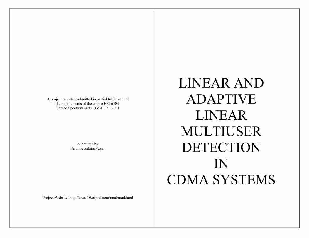
A project reported submitted in partial fulfillment of the requirements of the course EEL6503: Spread Spectrum and CDMA, Fall 2001
Submitted by Arun Avudainaygam
Project Website: http://arun-10.tripod.com/mud/mud.html
LINEAR AND ADAPTIVE
LINEAR MULTIUSER DETECTION
IN CDMA SYSTEMS

SECTION 0
Introduction
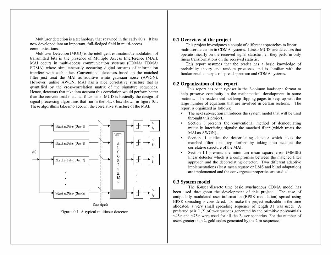
Multiuser detection is a technology that spawned in the early 80’s. It has now developed into an important, full-fledged field in multi-access communications. Multiuser Detection (MUD) is the intelligent estimation/demodulation of transmitted bits in the presence of Multiple Access Interference (MAI). MAI occurs in multi-access communication systems (CDMA/ TDMA/ FDMA) where simultaneously occurring digital streams of information interfere with each other. Conventional detectors based on the matched filter just treat the MAI as additive white gaussian noise (AWGN). However, unlike AWGN, MAI has a nice correlative structure that is quantified by the cross-correlation matrix of the signature sequences. Hence, detectors that take into account this correlation would perform better than the conventional matched filter-bank. MUD is basically the design of signal processing algorithms that run in the black box shown in figure 0.1. These algorithms take into account the correlative structure of the MAI.
Figure 0.1 A typical multiuser detector
0.1 Overview of the project This project investigates a couple of different approaches to linear multiuser detection in CDMA systems. Linear MUDs are detectors that operate linearly on the received signal statistic i.e., they perform only linear transformations on the received statistic. This report assumes that the reader has a basic knowledge of probability theory and random processes and is familiar with the fundamental concepts of spread spectrum and CDMA systems.
0.2 Organization of the report This report has been typeset in the 2-column landscape format to help preserve continuity in the mathematical development in some sections. The reader need not keep flipping pages to keep up with the large number of equations that are involved in certain sections. The report is orgainzed as follows: • The next sub-section introduces the system model that will be used
throught this project. • Section I presents the conventional method of demodulating
mutually interfering signals: the matched filter (which treats the MAI as AWGN).
• Section II studies the decorrelating detector which takes the matched filter one step further by taking into account the correlative structure of the MAI.
• Section III presents the minimum mean square error (MMSE) linear detector which is a compromise between the matched filter approach and the decorrelating detector. Two different adaptive implementations (least mean square or LMS and blind adaptation) are implemented and the convergence properties are studied.
0.3 System model The K-user discrete time basic synchronous CDMA model has been used throughout the development of this project. The case of antipodally modulated user information (BPSK modulation) spread using BPSK spreading is considered. To make the project realizable in the time allocated, a very small spreading sequence of length 31 was used. A preferred pair [1,2] of m-sequences generated by the primitive polynomials <45> and <75> were used for all the 2-user scenarios. For the number of users greater than 2, gold codes generated by the 2 m-sequences

described above were used. See Appendix A for a list of codes in this project. Unless otherwise mentioned, in all the simulations perfect power control is assumed (i.e, the received amplitudes of all the users are assumed to be the same. The signal at the receiver is given by
∑=
+=K
1kkkk n(t)(t)sbAy(t) ………………………………(0.1)
, where • sk is the signature waveform of the kth user (sk is normalized to
have unit energy i.e., < sk ,sk > =1). For BPSK spreading with an m-sequence of length 31, the signature waveform is defined as
∑=
=30
0kcTkk )kT-(tpa(t)s , T=bit period, Tc =chip interval… (0.2)
where ak represents the normalized spreading sequence. • bk is the input bit of the kth user, bk ∈ {-1,1}. • Ak is the received amplitude of the kth user. • n(t) is additive white gaussian noise with PSD No .
Since synchronous CDMA is considered, it is assumed that the receiver has some means of achieving perfect chip synchronization. The cross-correlation of the signature sequences are defined as
∑=
==N
1kjijiij (k)(k)ssssρ ………………………………(0.3)
where N is the length of the signature sequence (31 in our case). The cross-correlation matrix is then defined as R={ρij}
i.e.,
=
KKKK
K
K
ρρρ
ρρρρρρ
21
212221
11211
�
�
���
�
�
R ……………………….………(0.4)
R is a symmetric, non-negative definite, toeplitz matrix.

SECTION I
TheMatched-Filter
Bank
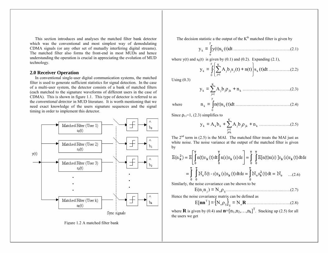
This section introduces and analyses the matched filter bank detector which was the conventional and most simplest way of demodulating CDMA signals (or any other set of mutually interfering digital streams). The matched filter also forms the front-end in most MUDs and hence understanding the operation is crucial in appreciating the evolution of MUD tech 2.0 er Operation I tional single-user digital communication systems, the matched filte to generate sufficient statistics for signal detection. In the case of a ser system, the detector consists of a bank of matched filters (eac d to the signature waveforms of different users in the case of CDM is is shown in figure 1.1. This type of detector is referred to as the c nal detector in MUD literature. It is worth mentioning that we need knowledge of the users signature sequences and the signal timi er to implement this detector.
The decision statistic a the output of the Kth matched filter is given by
(t)dty(t)sy0
kk ∫=T
………………..………………….(2.1)
where y(t) and sk(t) is given by (0.1) and (0.2). Expanding (2.1),
(t)dtsn(t)(t)sbAy0
k
K
1jjjjk ∫ ∑
+==
T
…………….(2.2)
Using (0.3)
∑=
+=K
1jkjkjjk nρbAy ……………………………..(2.3)
where (t)dtn(t)sn0
kk ∫=T
……….…………………………(2.4)
Since ρ11=1, (2.3) simplifies to
nology.
Receivn convenr is used multi-uh matche
A). Thonventio exact
ng in ord
∑≠=
++=K
kj1j
kjkjjkkk nρbAbAy …………………..(2.5)
The 2nd term in (2.5) is the MAI. The matched filter treats the MAI just as white noise. The noise variance at the output of the matched filter is given by
Similarly, the noise covariance can be shown to be
ijoji ρN)nE(n = …………………………………..……(2.7) Hence the noise covariance matrix can be defined as
{ } Rnn oijijoT NρN]E[ == …………………………..(2.8)
where R is given by (0.4) and n=[n1,n2,…,nk]T. Stacking up (2.5) for all the users we get
Figure 1.2 A matched filter bank
…(2.6)

+
=
K
2
1
K
2
1
2
1
21
212221
11211
K
2
1
n
nn
b
bb
A00
0A000A
ρρρ
ρρρρρρ
y
yy
���
�
���
�
�
�
�
���
�
�
�
KKKKK
K
K
….......(2.9)
∴ In matrix notation we have, y=RAb+n………………………………………………(2.10)
Figure 2.2 shows the error rate performance of the bank of matched filters. The simulation scenario is explained in section 0.3. It is observed that as the MAI increases (the number of users increases) the performance becomes poor. This is because the detector ignores the cross-talk between users (the MAI) as white noise. Good MUDs, as described in the next few sections, take into the account the correlative property of the cross-talk.
2.1 Limitations of the conventional detector Although {y1,y2,…,yk} are sufficient statistics for detecting {b1,b2,…,bk}, yk is not a sufficient statistic for detecting bk. The conventional detector makes the mistake of making this assumption (yk is a sufficient statistic for detecting bk) by ignoring the MAI as background noise. This is one reason for the poor performance of the matched filter bank when the number of users is large. Another serious limitation of the conventional detector is that it is seriously affected by the near-far problem. This causes a significant degradation in the system performance even when the number of users is very small. This fact will now be illustrated with an example. This example is a condensed version of a scenario described in [3]. Adapting (2.5) to the 2 user scenario we get,
1122j2111 nρbAbAy ++= ……………………………..(2.11) It is now obvious that the bit error probability for user 1 is
−+
+=
o
1221
o
1221s N
ρAAQ
NρAA
Q21P
1………(2.12)
The probability of bit error is then readily upper bounded as
−≤
o
1221s N
ρAAQ
21P
1……………………….………(2.13)
The fact that Q is a monotonically decreasing function was used to get the upper bound. If the interferer is not dominant i.e., A2ρ12<A1, the bit error probability is less than half. But if the interferer is dominant (near-far problem) i.e., A2ρ12>A1, the bound becomes greater than half. Consider the case when there is no noise in the system (i.e., No=0) and the interferer
is dominant, then (2,13) gives 21P
1s = . This is because the polarity of the
matched filter outputs is now governed by b2 rather than b1. Hence we see that in the absence of noise, though highly hypothetical, the matched filter receiver reduces to flipping a coin and deciding the output bits. This is an undesirable feature of the conventional detector (may perform better in the presence of noise than in the absence of noise).
Figure 1.2 B.E.R performance of the matched filter bank detector (perfect power control)

2.2 The conventional detector as a front end to MUDs The front end of any MUD has a section to convert the continuous-time received signal to a discrete-time process. This is usually done by sampling or it can also be done using the matched filter bank. As shown earlier, the conventional detector takes the received signal y(t) and outputs the statistic y={y1,y2,…,yk}T. It has been proved [3] that the matched filter bank sacrifices no information relevant to demodulation. Hence y(t) can be replaced by y without any loss in system performance. Most MUDs therefore have the matched filter as the front end. With the matched filter front end, the objective of MUD can be stated as follows: Given the statistic {y1,y2,…,yk} at the output of the matched filter, find an estimate for the transmitted bits {b1,b2,…,bk} that minimizes the probability of error.
SECTION II
TheDecorrelating
Detector
While concluding Section 2.1 it was noted that the matched filter bank may decode erroneously even in the absence of background AWGN. This is not a very attractive property for any receiver. An optimal receiver must be capable of decoding the bits error-free when the noise power is zero. In this section the decorrelating detector is investigated. This detector makes use of the structure of MAI to improve the performance of the matched filter bank. The decorrelating detector falls into the category of linear multiuser detectors. This fact will be substantiated as this section progresses. 2.0 Receiver Operation
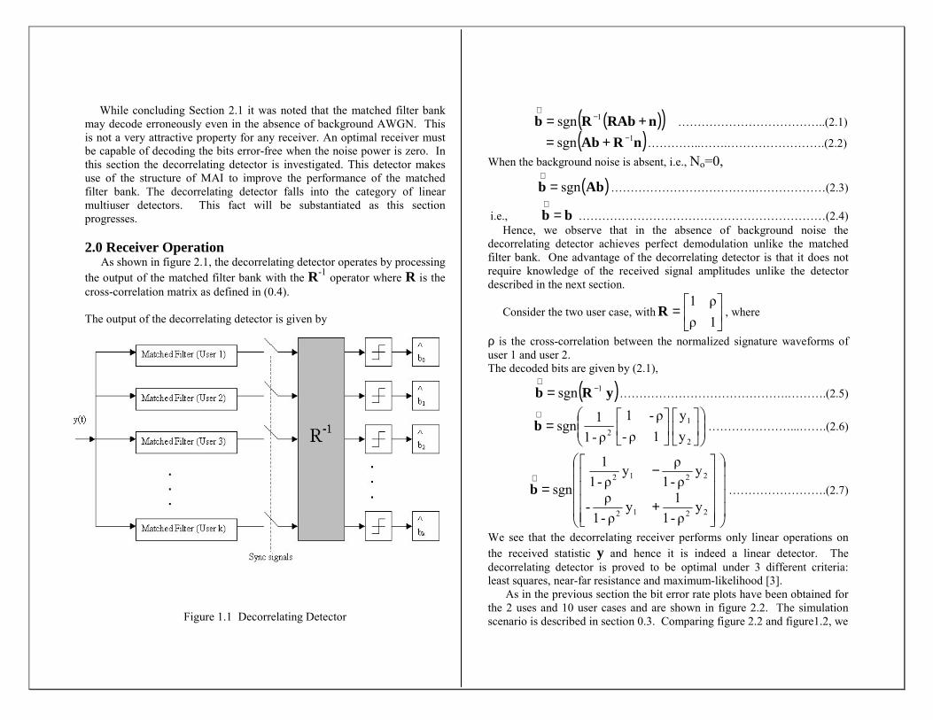
As shown in figure 2.1, the decorrelating detector operates by processing the output of the matched filter bank with the R-1 operator where R is the cross-correlation matrix as defined in (0.4).
The output of the decorrelating detector is given by
Figure 1.1 Decorrelating Detector
( )( )nRAbRb += −∧
1sgn ………………………………..(2.1)
( )nRAb 1sgn −+= …………..…….…………………….(2.2) When the background noise is absent, i.e., No=0,
( )Abb sgn=∧
……………………………….………………(2.3)
i.e., bb =∧
………………………………………………………(2.4) Hence, we observe that in the absence of background noise the decorrelating detector achieves perfect demodulation unlike the matched filter bank. One advantage of the decorrelating detector is that it does not require knowledge of the received signal amplitudes unlike the detector described in the next section.
Consider the two user case, with
=
1ρρ1
R , where
ρ is the cross-correlation between the normalized signature waveforms of user 1 and user 2. The decoded bits are given by (2.1),
( )yRb sgn 1−∧
= …………………………………….……….(2.5)
=
∧
2
12 y
y
1ρ-ρ-1
ρ-11sgnb …………………...…….(2.6)
+
−=
∧
yρ-11y
ρ-1ρ-
yρ-1ρy
ρ-11
sgn2212
2212
b …………………….(2.7)
We see that the decorrelating receiver performs only linear operations on the received statistic y and hence it is indeed a linear detector. The decorrelating detector is proved to be optimal under 3 different criteria: least squares, near-far resistance and maximum-likelihood [3]. As in the previous section the bit error rate plots have been obtained for the 2 uses and 10 user cases and are shown in figure 2.2. The simulation scenario is described in section 0.3. Comparing figure 2.2 and figure1.2, we
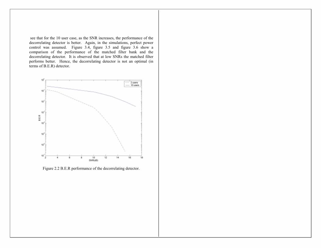
see that for the 10 user case, as the SNR increases, the performance of the decorrelating detector is better. Again, in the simulations, perfect power control was assumed. Figure 3.4, figure 3.5 and figure 3.6 show a comparison of the performance of the matched filter bank and the decorrelating detector. It is observed that at low SNRs the matched filter performs better. Hence, the decorrelating detector is not an optimal (in terms of B.E.R) detector.
Figure 2.2 B.E.R performance of the decorrelating detector.

SECTION III
TheMMSE Linear
Detector

In section II we noted that the only information required by the decorrelating detector was the cross-correlation matrix R of the spreading sequences. At low SNRs, the matched filter bank performs better than the decorrelating detector as observed from figure 3.6. Hence, it might be possible to improve the performance by incorporating some SNR information in the MUD algorithms. In this section, one such approach is investigated where the mean squared error between the output and data is minimized. The detector resulting from the MMSE (minimum mean square error) criterion is a linear detector. Two different adaptive approaches of the MMSE linear detector are also studied at the end of this section. One of the approaches requires no prior information of the SNRs or the signature waveforms but requires a training sequence to adapt and compute the optimum weights to be applied on the received statistic. The other approach does not need a training sequence but requires exact knowledge of the signature sequence. 3.0 Receiver Operation Being a linear detector like the decorrelating detector, the MMSE receiver also weights the received statistic y with a weight vector w to form the decision statistic. The receiver structure for user m is shown in figure 3.1.
Figure 3.1 MMSE linear transformation for user m
It has been proved that minimizing the MSE at the output of the linear transformation is equivalent to maximizing the SIR at the output of the linear transformation [3]. The optimal value of the [w1,w2,…wk] that
minimizes the MSE between the weighted received statistic and the transmitted bit is derived in the next section. 3.0.1 Optimal Weights for an MMSE Linear Detector in
an AWGN Channel The MMSE linear detector for user 1 determines a waveform c1(t) such that the MSE error between the transmitted bit and the correlation between c1(t) and the received signal y(t) is minimized. The objective function (the mean square error in this case) is defined as
( ){ }2 1 y,1cbEc1)( −=Ψ …………………………………………(3.1)
In the finite dimensional representation (3.1) can be expressed as
−=Ψ ∑=
2K
1iii 1K21 ywbE)w,...,w,w( …………………….(3.2)
Where {w1, w2, … , wK} are the weights operating on the received statistic { y1, y2,…, yK}. Representing (3.2) in a compact and convenient matrix notation,
( ){ }2T 1bE)( yww −=Ψ ……………………………………………(3.3)
Using linearity of the Expectation operator,
( ) ( ) ( )( ){ }TTTT1
21 E2bEbE)( ywywyww +−=Ψ ……………….(3.4)
Since the bits of user 1 are i.i.d, ( ) 1bE 2
1 = . Therefore,
( ) { }wyywyww TT1
T EbE21)( +−=Ψ …………………………(3.5)
( ) { }wyywyw TT1
T EbE21 +−= …………………………(3.6) From (2.10), we have nRAby += ……………………………….………………………(3.7)
Consider, ( ) ( )nRAby 111 bbEbE += ………………………...…(3.8)
( )nRA 1
K
2
1
1 bE
b
bb
bE +
=�
…………………………(3.9)
( )( )
( )
( )nRA Eb
bbE
bbEbE
1
K1
21
21
+
=�
………………………….(3.10)
Since the bits of user 1 are i.i.d and are uncorrelated with the bits of other users we have,
( )
=≠
= ji, 1ji, 0
bbE K1 ……………………………….(3.11)
Using (3.11) and the fact that the noise n is zero mean i.e.,E(n)=0 in (3.10),
( ) [ ]T0 0 0 1bE 1 �RAy = ……………………………….…(3.12)
Using the definition of A and R from (0.4)and (2.9),
( )
=
0 01
A00
0A000A
ρρρ
ρρρρρρ
bE 2
1
21
212221
11211
1��
�
���
�
�
�
�
���
�
�
KKKKK
K
K
y ..(3.13)
( )
=∴
11K
121
111
1
Aρ
AρAρ
bE�
y ……………………………………(3.14)
Now consider the second expectation term in (3.6),
{ } ( )( ){ } ( )TTT EEE nnRAbRAbyy += [using (3.7)]………(3.15)
{ } RRARAbb oTTT NE += [using (1.3) ]……..(3.16)
Using the fact that A and R are symmetric matrices, we get { } { } RARbbRAyy o
TT NE E += …………………..………….(3.17)
RRRA o2 N += …………………………….………….(3.18)
Substituting (3.14) and (3.18) in (3.6),
[ ]( )wRRRAw
ww N
Aρ Aρ Aρ21)(
o2T
T 1K121111
T
++
−=Ψ �
…(3.19)
Equation (3.19) gives the objective function (MSE) that should be minimized according to the MMSE criterion. Performing a matrix derivative operation on (3.19) we get,
[ ]( )wRRRA
ww
N2
Aρ Aρ Aρ2)(
o2
T 1K121111
++
−=Ψ∇ �
………..(3.20)
We used the fact that ( ) No2 RRRA + is a symmetric matrix to get
(3.20). The optimum weights that minimize the MSE can be obtained by equating )(wwΨ∇ to zero. Hence,
[ ] ( ) 0 N2 Aρ Aρ Aρ2 opto2T
1K121111 =++− wRRRA� ….(3.21)
Solving (3.21) the optimal weights are obtained as
( ) [ ] T 11K121111
1o
2opt Aρ Aρ AρN �
−+= RRRAw ……...(3.22)
To calculate the optimal weights for user m, just replace i1ρ by m iρ for all i and replace A1 by Am in (3.22). (3.22) can be written in a more general and compact form as
( ) 12oopt N −−+= ARw ………………………………………..….(3.23)
where
= 2K
o22
o21
o2-o A
N,...,
AN
,AN
N diagA ……………………….(3.24)
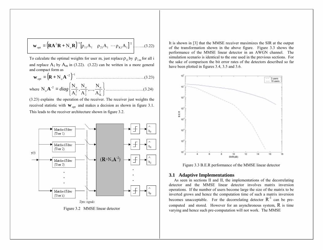
(3.23) explains the operation of the receiver. The receiver just weights the received statistic with optw and makes a decision as shown in figure 3.1. This leads to the receiver architecture shown in figure 3.2.
Figure 3.2 MMSE linear detector
It is shown in [3] that the MMSE receiver maximizes the SIR at the output of the transformation shown in the above figure. Figure 3.3 shows the performance of the MMSE linear detector in an AWGN channel. The simulation scenario is identical to the one used in the previous sections. For the sake of comparison the bit error rates of the detectors described so far have been plotted in figures 3.4, 3.5 and 3.6.
Figure 3.3 B.E.R performance of the MMSE linear detector
3.1 Adaptive Implementations As seen in sections II and II, the implementations of the decorrelating detector and the MMSE linear detector involves matrix inversion operations. If the number of users become large the size of the matrix to be inverted grows and hence the computation time of such a matrix inversion becomes unacceptable. For the decorrelating detector R-1 can be pre-computed and stored. However for an asynchronous system, R is time varying and hence such pre-computation will not work. The MMSE
detector requires the SNR information and hence again precomputation of the matrix inverse is not a feasible solution. Also, getting good estimates of the SNR is not temporally efficient. Therefore, it would be nice if there was some way to eliminate the need to compute matrix inverses and the need to have apriori information (signature sequences) and other additional information (SNR) for decoding. This objective can be realized through adaptive MUD algorithms. Adaptive algorithms “learn” the desired filter response from the received signals. There are different approaches to implement the “learning” capability. Two approaches will be studied in the next sub-sections. The first approach does not any apriori knowledge but calls for a training sequence. The second approach does not require any training sequence but requires exact knowledge of the signature sequences of the users and also takes longer to converge.
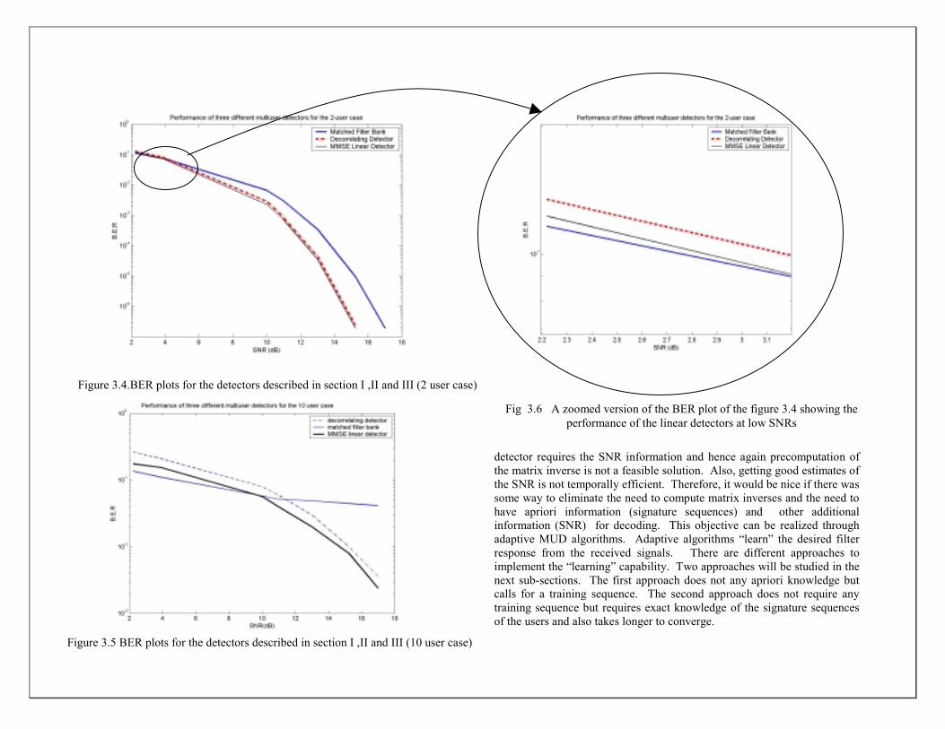
Figure 3.4.BER plots for the detectors described in section I ,II and III (2 user case)
Figure 3.5 BER plots for the detectors described in section I ,II and III (10 user case)
Fig 3.6 A zoomed version of the BER plot of the figure 3.4 showing the
performance of the linear detectors at low SNRs
3.1.1 Adaptive MMSE Linear Detection (LMS Algorithm) Before the LMS (least mean square) algorithm is described, a brief review of the gradient descent optimization algorithm is presented. A more detailed presentation of this algorithm can be found in [3,4] The gradient descent algorithm is used for the optimization of convex penalty functions. Consider the optimization of the following convex penalty function :
u)]E[g(X,)u( =Ψ ……………………………………….(3.25) where E is the expectation operator , X is a random variable and u is the parameter to be optimized (X and u could be vectors). If ψ is convex, then according to the gradient descent algorithm, it is possible to converge to the minimum valuse of ψ by starting at any point uo and following the direction opposite to the gradient ∇ψ (steepest descent). The update rule is then given by
( )jj1j uµ-uu Ψ∇=+ , where µ is the step size…..…….(3.26)
However, if the distribution of X is not known then neither the penalty function given by (3.25) nor its gradient can be computed. But if a number of independent observations of X are available then it would be possible to get an estimate of the distribution of X and calculate the gradient of the penalty function and use the update rule given in (3.26). Therefore, at each iteration we could replace the gradient of the penalty function, ∇ψ =E[∇ g(X,u)] by its approximate value ∇ g(Xj+1,u). This is called the stochastic gradient descent algorithm. The update rule for the stochastic gradient is thus modified as
( )j1jj1j u,Xgµ-uu ++ ∇= …………………….……..(3.27) If the step size is infinitesimally small, then the deviations on either side of the mean tend to cancel out and the trajectory of the stochastic descent will almost follow the steepest descent trajectory. For the special case of quadratic cost functions, the stochastic descent algorithim is also known as the least mean square (LMS) algorithm. For the case of MMSE multiuser detection in CDMA systems, the convex penalty function is given by (3.3) . Hence
( )2T 1b),(g ywwX −= , where X=(b1, w)………...(3.28)
Differentiating w.r.t w, ( )yywwX b2),(g T 1 −−=∇ ………….(3.29)
Since Xj=(b1[j], y[j]), the update rule in (3.27) becomes
( ) ]j[ ]j[b-[j]]1-j[µ-]1-j[]j[ 1T yywww = …….(3.30)
It is seen that we need to know the data bits b1 in order to implement the LMS algorithm. This requirement is handled by sending a training sequence at the beginning of each transmission. Once the training sequence has been sent, the adaptive algorithm can be allowed to run with the decisions made by the detector instead of the true transmitted data. This mode of operation is called decision directed operation.This might fine tune the weights if the SNR is high enough. However if the SNR is very low, the decisions of the detector are not reliable enough and may cause the weight to change drastically from the optimal value. In the simulation results presented in this report, the decision directed mode was not used. Once the training bits are sent, the weights were not changed. The longer the training sequence, the closer are the computed weights to the optimal value given by (3.23). The training bits however are a overhead and the number of training bits needs to be as small as possible in order to maintain system efficiency. Hence there is a tradeoff between efficiency and error performance that needs to be considered when deteremining the number of training bits that needs to be used in a system. This is observed by comparing figure 3.7 and figure 3.9 which show that the weights w1 and w2 (in the 2 user case) do not converge to the optimal value with just 1000 training bits. However when 5000 training bits are sent, the weight vectors were closer to the optimal value (as observed from the MSE curve, figures 3.8 and 3.10 ). The simulations were run with an SNR of 10dB and the optimal values required to calculate the MSE were obtained from (3.23). Apart from the number of training bits another important parameter that affects the performance and convergence speed of the the LMS algorithm is the step size. A larger step size makes the algorithm converge faster but has a higher ripple around the optimal value. This can be observed by comparing figures 3.9and 3.13 and also figures 3.10 and 3.14.
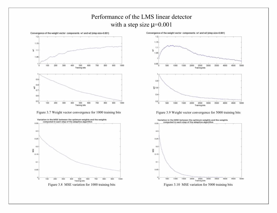
Figure 3.7 Weight vector convergence for 1000 training bits
Figure 3.9 Weight vector convergence for 5000 training bits
Figure 3.10 MSE variation for 5000 training bits Figure 3.8 MSE variation for 1000 training bits
Performance of the LMS linear detector with a step size µ=0.001
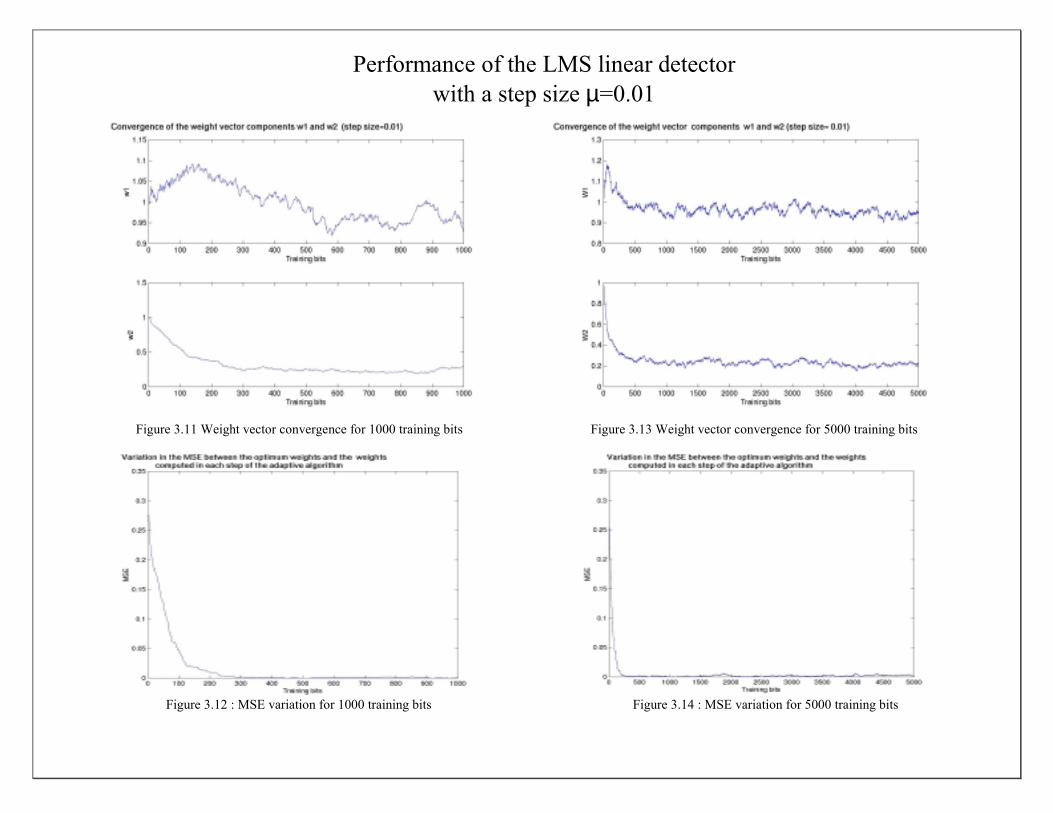
Figure 3.11 Weight vector convergence for 1000 training bits
Figure 3.13 Weight vector convergence for 5000 training bits
Figure 3.12 : MSE variation for 1000 training bits Figure 3.14 : MSE variation for 5000 training bits
Performance of the LMS linear detector with a step size µ=0.01

Observing figure 3.7 and figure 3.11 we see that with a larger step size, the weights converge to the optimal value with a smaller number of training bits but at the cost of a higher residual error (weights do not converge to optimal value with a step size of 0.001 and 1000 training bits but if the step size is increased to 0.01, the weight vectors converge around the optimal value with just 1000 bits). Conversely, a smaller step size takes longer to converge(requires more training bits) . From the above discussion, it is clear that it would be nice to progressively decrease the step size as the LMS algorithm proceeds. A high value of step size should be used initially to cause fast convergence of the the algorithm and then in the latter iterations a smaller step size should be used to minimize the ripple around the optimal value (residual error). But great care should be excercised in using adaptive step sizes. Sometimes the step size may become really small as the algorithm progresses and the weights may never converge to the optimal value. One method of progressively shrinking the step size is to multiply a fixed step size by γi where i is the iteration number and γ is a number just smaller than 1. Hence the update rule is given by
( ) ]j[ ]j[b-[j]]1-j[µ-]1-j[]j[ 1Ti yywww γ= …………(3.31)
The convergence of the weights with this adaptive step size is shown in figure 3.15. In the simulations, γ =0.995 and µ=0.01. We can see that the step size becomes very small as the algorithm progresses and the weights do not converge. Hence, this is not a suitable strategy for varying the step size in this case. Another method of progressively decreasing the step size is to have a step size of the form 1/i, where i is the iteration number. Hence the update rule is modified as
( ) ]j[ ]j[b-[j]]1-j[i1-]1-j[]j[ 1
T yywww = ……………(3.32)
The convergence plots for this step size is given in Figure (3.16). Also plotted are convergence plots with a fixed step size of 0.01 for comparison. We see that this method of varying the step size converges very fast to the vicinit of the optimal value. For the a step size of the form 1/i it has been proved [3] that the update rule given in (3.32) will always converge to the optimum value. If the channel changes often, then training bits need to be sent periodically. The choice of step size, whether it should be fixed or stationary, depends on the application, channel and other cost factors. Since, the detector requires no knowledge of the signature sequence, why
Figure 3.16 Weight vector convergence for the update rule in (3.32) Figure 3.15 Weight vector convergence for the update rule in (3.31)
doesn’t the detector converge to some other users MMSE detector (say the user with the strongest power)? This is because of the training sequence which governs the desired users LMS algorithm. Hence, each user should have a different training sequence. Hence, we see that the LMS MUD is not limited by the near far problem. 3.1.2 Blind Adaptive Multiuser Detection The convergence of the LMS algorithm rests on the fact that the received amplitudes, cross-correlations and channel conditions remain constant. If any of these parameters change suddenly (a strong interfere is powered on or the channel suddenly goes into a deep fade), then in the decision directed mode of operation the weights may not converge because the detector starts making faulty decisions or in the fixed mode of operation the weights are no longer optimal. This calls for the training sequence to be sent again. Thus, the detector needs to be able to detect sudden changes in the system environment and request for the training sequence to be sent again. This is a cumbersome procedure requiring a lot of overhead. Hence, it is desirable to have an adaptive algorithm that operates without having to know the data. Algorithms that operate without knowledge of the channel input are known as blind algorithms (the algorithm is blind to the data). Blind adaptive multiuser detection was first introduced by Honig et al in 1995 [5]. Before the blind MUD algorithm is presented the canonical representation of linear multiuser detection introduced in [5] is discussed. The blind MUD approach is based on decomposing the linear MUD filter response into two orthogonal components. One of the components is equal to the signature waveform of the desired user. Consider the linear detector of user 1 which is characterized by the filter response c1,
)cy,sgn(b 11 ><=∧
………………………………....(3.33) The canonical representation of c1 is
c1= s1+ x1……………………………………………(3.34) where <s1, x1>=0….………………………………………………(3.35)
s1 in (3.34) and (3.35) is the signature waveform of user 1. Therefore, according to the canonical representation every linear MUD is characterized by its orthogonal signal x1 (since s1 is assumed to be known). Given a linear transformation d1 the orthogonal component is given by
1111
1 sdd,s
1x −><
= …………………………………..(3.36)
This can be verified by applying (3.35) to (3.36). Using (3.34) in (3.33) we have,
)xsy,sgn(b 111 >+<=∧
……………………………..….(3.37) Using the definition of y from (0.1)
( )~
1
K
2k1k1kkk111 nx,sρbAbsgn(Ab +><++= ∑
=
∧……(3.38)
Just as done in section 3.0.1, it can be proved that
2~
21 x1n E +=
………………………………………………..(3.39)
The variance at the output of the linear transformation in (3.37) is given as { }2
11 )xsy,(E >+< ……………………………………………(3.40) This is also referred to as the output energy in literature. Using the definition of <y,s1+x1> in (3.40) we can express the output energy as
……………………..(3.41)
We have used the fact that the bits of user 1 are uncorrelated with the bits of the other users and the noise. The first term in (3.41) is the signal energy and the two other terms represent the interference energy (MAI + noise). Due to the canonical representation we can see that the signal energy is transparent to the choice of x1. We can intuitively see that choosing x1to minimize the output energy would be a sensible idea since this would just minimize the interference energy. This type of detector is referred to as the minimum output energy (MOE) detector. Denote the minimum output energy as
{ }2111 )xsy,(E)x(MOE >+<= ……………………….(3.42)
From section 3.01, the minimum MSE is given by { }2
11111 )xsy,-b(AE)x(MSE >+<= ……………….(3.43)
i.e., ( ) ( )2o
2K
2k1k1k
2k1 x1Nx,sρA)MSE(x ++><+=∑
=
….(3.44)
=> 2111 A)MOE(x)MSE(x −= (using (3.41)) ………………(3.45)
∴ We can see that the MSE and MOE differ only by a constant (thanks to the canonical representation). Hence, the arguments that minimize both the functions are the same. This is a crucial observation from the point of view of the adaptive implementation. It tells us that if we try to minimize the MOE (same as minimizing the MSE), we do not need any training sequence to implement the gradient descent algorithm (since the MOE does not depend on the data). Hence we end up with an adaptive MMSE detector without the need for any training sequence. This is the basis for the blind adaptive multiuser detector. The steepest descent algorithm (described in the previous subsection) is again used to derive the update rule for the adaptive algorithm. We just need to update the orthogonal component to s1 since we are trying to obtain the minimum of the MOE by changing just x1. Therefore we just need to follow the steepest descent in the direction orthogonal to s1. To do this we just take the gradient of the MOE and project it on the subspace orthogonal to s1. The gradient of the MOE given in (3.42) is
yxsy,2)x(MOE 111 >+<=∇ ………………..……………..(3.46) The component orthogonal to s1 is y- <y,s1> s1. Using this in (3.46) we get the gradient projected onto a subspace orthogonal to s1 as
2< y,s1+x1>[y- <y,s1> s1]…………………..……….(3.47) The adaptive algorithm update is done once every T seconds, where T is the bit period. The received waveform is slotted into waveforms of duration T,
...y[i-1], y[i], y[i+1]…
Define, ><=∆
1MF sy[i],]i[Z …………………..……….…….…(3.48)
>−+<=∆
1][ixsy[i],]i[Z 11 ……………………….(3.49) Using (3.49) and (3.48) in (3.47) and using the update rule in (3.27), the update rule for the blind adaptive MUD is given by
( )1MF11 [i]sZy[i]µ Z[i]1][ix[i]x −−−= …………(3.50)
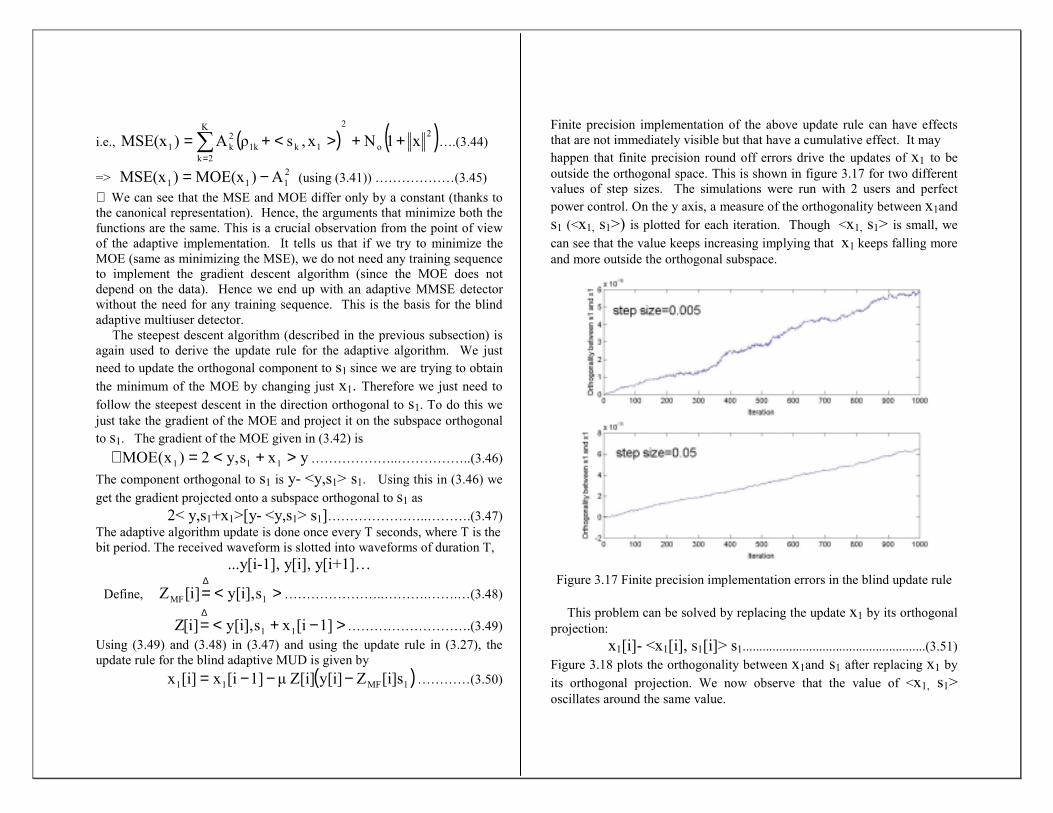
Finite precision implementation of the above update rule can have effects that are not immediately visible but that have a cumulative effect. It may happen that finite precision round off errors drive the updates of x1 to be outside the orthogonal space. This is shown in figure 3.17 for two different values of step sizes. The simulations were run with 2 users and perfect power control. On the y axis, a measure of the orthogonality between x1and s1 (<x1, s1>) is plotted for each iteration. Though <x1, s1> is small, we can see that the value keeps increasing implying that x1 keeps falling more and more outside the orthogonal subspace.
Figure 3.17 Finite precision implementation errors in the blind update rule
This problem can be solved by replacing the update x1 by its orthogonal projection:
x1[i]- <x1[i], s1[i]> s1.......................................................(3.51) Figure 3.18 plots the orthogonality between x1and s1 after replacing x1 by its orthogonal projection. We now observe that the value of <x1, s1> oscillates around the same value.
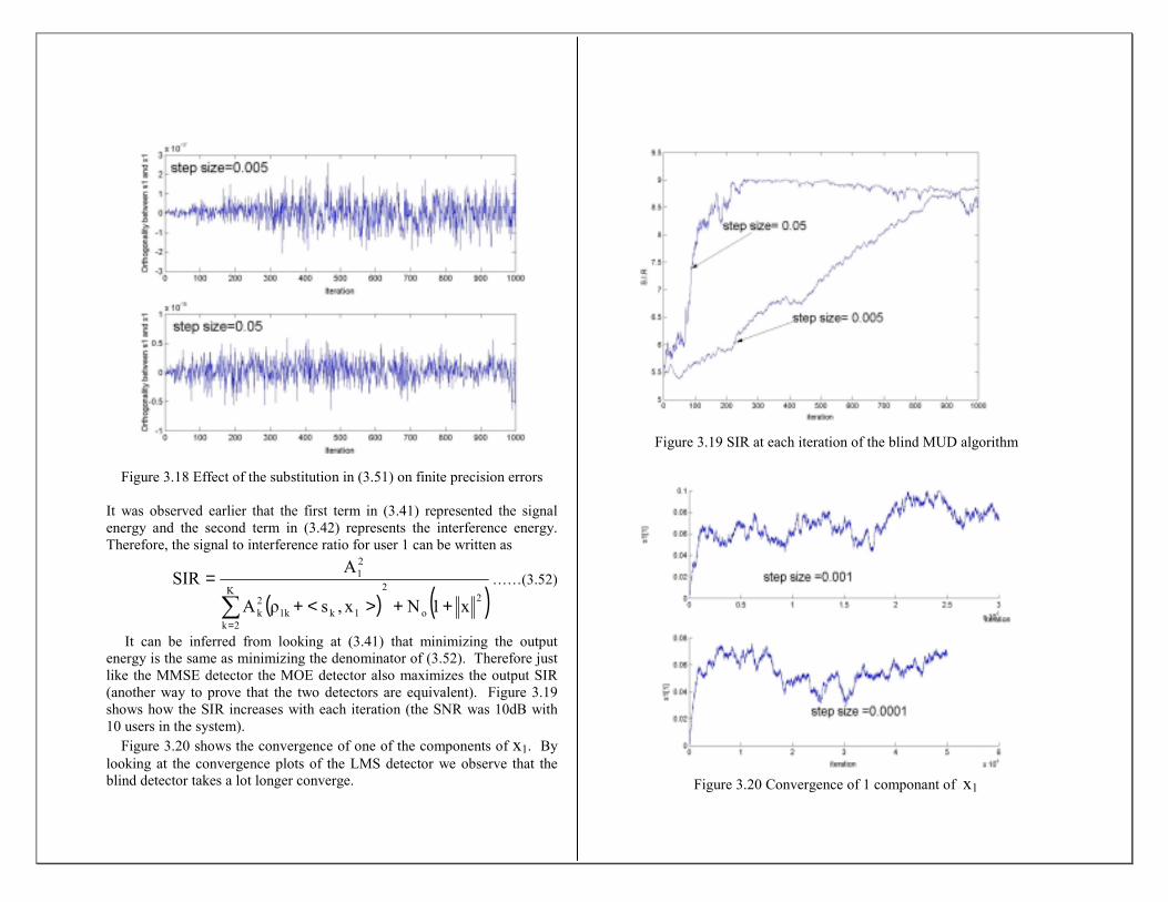
Figure 3.18 Effect of the substitution in (3.51) on finite precision errors
It was observed earlier that the first term in (3.41) represented the signal energy and the second term in (3.42) represents the interference energy. Therefore, the signal to interference ratio for user 1 can be written as
( ) ( )2o
2K
2k1k1k
2k
21
x1Nx,sρA
ASIR
++><+=
∑=
……(3.52)
It can be inferred from looking at (3.41) that minimizing the output energy is the same as minimizing the denominator of (3.52). Therefore just like the MMSE detector the MOE detector also maximizes the output SIR (another way to prove that the two detectors are equivalent). Figure 3.19 shows how the SIR increases with each iteration (the SNR was 10dB with 10 users in the system). Figure 3.20 shows the convergence of one of the components of x1. By looking at the convergence plots of the LMS detector we observe that the blind detector takes a lot longer converge.
Figure 3.19 SIR at each iteration of the blind MUD algorithm
Figure 3.20 Convergence of 1 componant of x1
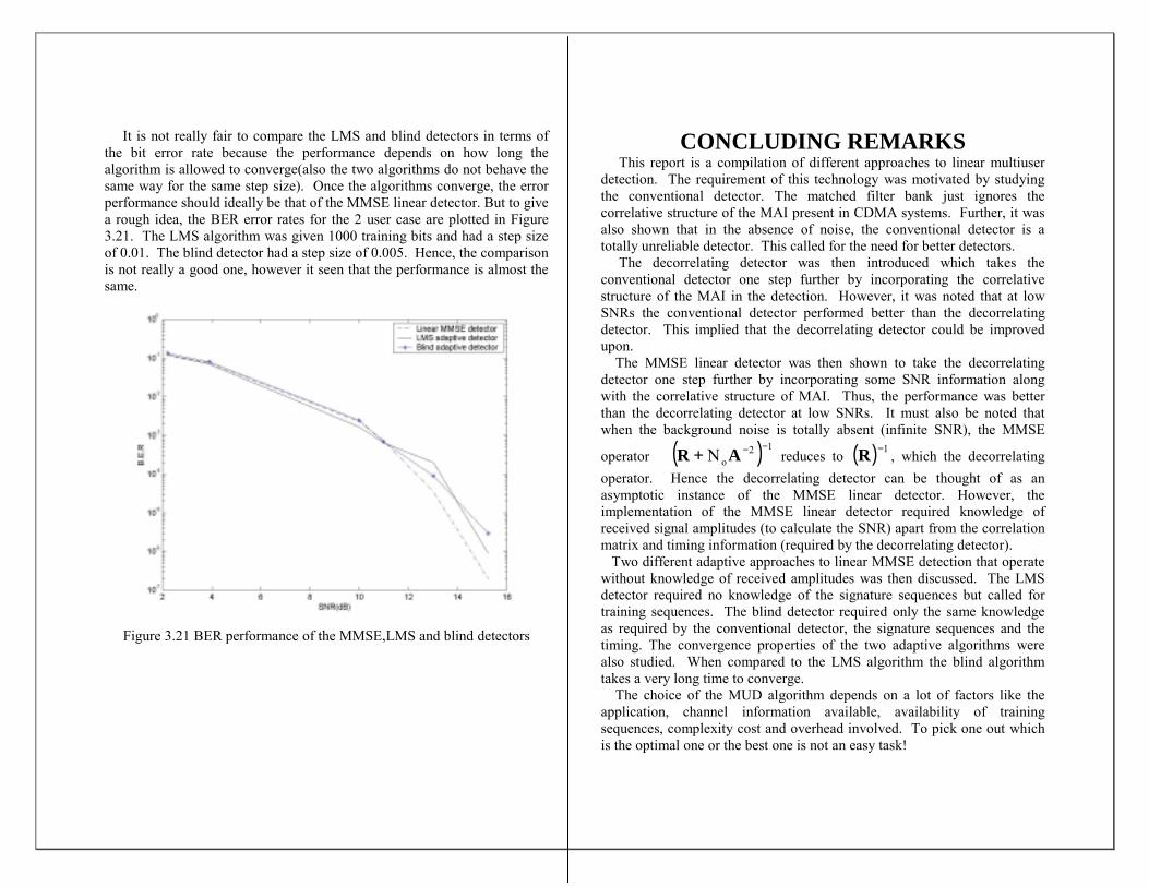
It is not really fair to compare the LMS and blind detectors in terms of the bit error rate because the performance depends on how long the algorithm is allowed to converge(also the two algorithms do not behave the same way for the same step size). Once the algorithms converge, the error performance should ideally be that of the MMSE linear detector. But to give a rough idea, the BER error rates for the 2 user case are plotted in Figure 3.21. The LMS algorithm was given 1000 training bits and had a step size of 0.01. The blind detector had a step size of 0.005. Hence, the comparison is not really a good one, however it seen that the performance is almost the same.
Figure 3.21 BER performance of the MMSE,LMS and blind detectors
CONCLUDING REMARKS This report is a compilation of different approaches to linear multiuser detection. The requirement of this technology was motivated by studying the conventional detector. The matched filter bank just ignores the correlative structure of the MAI present in CDMA systems. Further, it was also shown that in the absence of noise, the conventional detector is a totally unreliable detector. This called for the need for better detectors. The decorrelating detector was then introduced which takes the conventional detector one step further by incorporating the correlative structure of the MAI in the detection. However, it was noted that at low SNRs the conventional detector performed better than the decorrelating detector. This implied that the decorrelating detector could be improved upon. The MMSE linear detector was then shown to take the decorrelating detector one step further by incorporating some SNR information along with the correlative structure of MAI. Thus, the performance was better than the decorrelating detector at low SNRs. It must also be noted that when the background noise is totally absent (infinite SNR), the MMSE
operator ( ) 12oN −−+ AR reduces to ( ) 1−R , which the decorrelating
operator. Hence the decorrelating detector can be thought of as an asymptotic instance of the MMSE linear detector. However, the implementation of the MMSE linear detector required knowledge of received signal amplitudes (to calculate the SNR) apart from the correlation matrix and timing information (required by the decorrelating detector). Two different adaptive approaches to linear MMSE detection that operate without knowledge of received amplitudes was then discussed. The LMS detector required no knowledge of the signature sequences but called for training sequences. The blind detector required only the same knowledge as required by the conventional detector, the signature sequences and the timing. The convergence properties of the two adaptive algorithms were also studied. When compared to the LMS algorithm the blind algorithm takes a very long time to converge. The choice of the MUD algorithm depends on a lot of factors like the application, channel information available, availability of training sequences, complexity cost and overhead involved. To pick one out which is the optimal one or the best one is not an easy task!
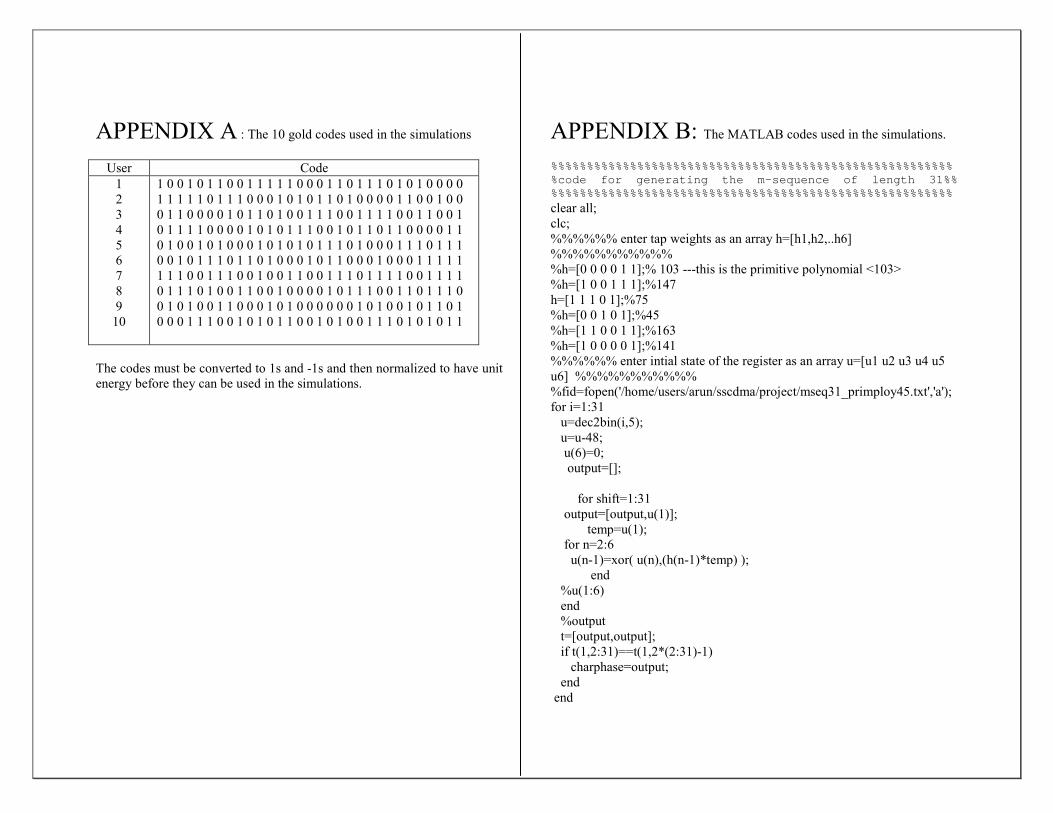
APPENDIX A : The 10 gold codes used in the simulations
User Code 1 2 3 4 5 6 7 8 9
10
1 0 0 1 0 1 1 0 0 1 1 1 1 1 0 0 0 1 1 0 1 1 1 0 1 0 1 0 0 0 0 1 1 1 1 1 0 1 1 1 0 0 0 1 0 1 0 1 1 0 1 0 0 0 0 1 1 0 0 1 0 0 0 1 1 0 0 0 0 1 0 1 1 0 1 0 0 1 1 1 0 0 1 1 1 1 0 0 1 1 0 0 1 0 1 1 1 1 0 0 0 0 1 0 1 0 1 1 1 0 0 1 0 1 1 0 1 1 0 0 0 0 1 1 0 1 0 0 1 0 1 0 0 0 1 0 1 0 1 0 1 1 1 0 1 0 0 0 1 1 1 0 1 1 1 0 0 1 0 1 1 1 0 1 1 0 1 0 0 0 1 0 1 1 0 0 0 1 0 0 0 1 1 1 1 1 1 1 1 0 0 1 1 1 0 0 1 0 0 1 1 0 0 1 1 1 0 1 1 1 1 0 0 1 1 1 1 0 1 1 1 0 1 0 0 1 1 0 0 1 0 0 0 0 1 0 1 1 1 0 0 1 1 0 1 1 1 0 0 1 0 1 0 0 1 1 0 0 0 1 0 1 0 0 0 0 0 0 1 0 1 0 0 1 0 1 1 0 1 0 0 0 1 1 1 0 0 1 0 1 0 1 1 0 0 1 0 1 0 0 1 1 1 0 1 0 1 0 1 1
The codes must be converted to 1s and -1s and then normalized to have unit energy before they can be used in the simulations.
APPENDIX B: The MATLAB codes used in the simulations. %%%%%%%%%%%%%%%%%%%%%%%%%%%%%%%%%%%%%%%%%%%%%%%%%%%%%%%%%code for generating the m-sequence of length 31%%%%%%%%%%%%%%%%%%%%%%%%%%%%%%%%%%%%%%%%%%%%%%%%%%%%%%%%%%clear all; clc; %%%%%% enter tap weights as an array h=[h1,h2,..h6] %%%%%%%%%%% %h=[0 0 0 0 1 1];% 103 ---this is the primitive polynomial <103> %h=[1 0 0 1 1 1];%147 h=[1 1 1 0 1];%75 %h=[0 0 1 0 1];%45 %h=[1 1 0 0 1 1];%163 %h=[1 0 0 0 0 1];%141 %%%%%% enter intial state of the register as an array u=[u1 u2 u3 u4 u5 u6] %%%%%%%%%%% %fid=fopen('/home/users/arun/sscdma/project/mseq31_primploy45.txt','a'); for i=1:31 u=dec2bin(i,5); u=u-48; u(6)=0; output=[]; for shift=1:31 output=[output,u(1)]; temp=u(1); for n=2:6 u(n-1)=xor( u(n),(h(n-1)*temp) ); end %u(1:6) end %output t=[output,output]; if t(1,2:31)==t(1,2*(2:31)-1) charphase=output; end end
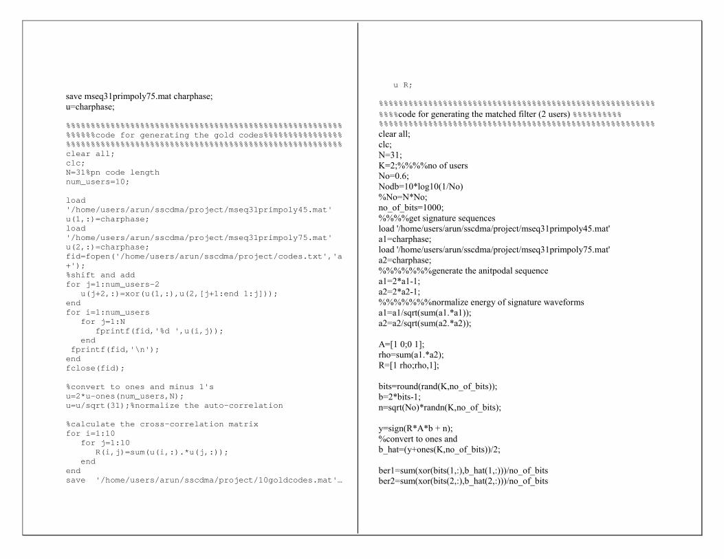
save mseq31primpoly75.mat charphase; u=charphase;
%%%%%%%%%%%%%%%%%%%%%%%%%%%%%%%%%%%%%%%%%%%%%%%%%%%%%%%%%%%%%%code for generating the gold codes%%%%%%%%%%%%%%%%%%%%%%%%%%%%%%%%%%%%%%%%%%%%%%%%%%%%%%%%%%%%%%%%%%%%%%%%clear all;clc;N=31%pn code lengthnum_users=10;
load'/home/users/arun/sscdma/project/mseq31primpoly45.mat'u(1,:)=charphase;load'/home/users/arun/sscdma/project/mseq31primpoly75.mat'u(2,:)=charphase;fid=fopen('/home/users/arun/sscdma/project/codes.txt','a+');%shift and addfor j=1:num_users-2
u(j+2,:)=xor(u(1,:),u(2,[j+1:end 1:j]));endfor i=1:num_users
for j=1:Nfprintf(fid,'%d ',u(i,j));
endfprintf(fid,'\n');
endfclose(fid);
%convert to ones and minus 1'su=2*u-ones(num_users,N);u=u/sqrt(31);%normalize the auto-correlation
%calculate the cross-correlation matrixfor i=1:10
for j=1:10R(i,j)=sum(u(i,:).*u(j,:));
endendsave '/home/users/arun/sscdma/project/10goldcodes.mat'…
u R;
%%%%%%%%%%%%%%%%%%%%%%%%%%%%%%%%%%%%%%%%%%%%%%%%%%%%%%%%
%%%%code for generating the matched filter (2 users) %%%%%%%%%% %%%%%%%%%%%%%%%%%%%%%%%%%%%%%%%%%%%%%%%%%%%%%%%%%%%%%%%%clear all; clc; N=31; K=2;%%%%no of users No=0.6; Nodb=10*log10(1/No) %No=N*No; no_of_bits=1000; %%%%get signature sequences load '/home/users/arun/sscdma/project/mseq31primpoly45.mat' a1=charphase; load '/home/users/arun/sscdma/project/mseq31primpoly75.mat' a2=charphase; %%%%%%%generate the anitpodal sequence a1=2*a1-1; a2=2*a2-1; %%%%%%%normalize energy of signature waveforms a1=a1/sqrt(sum(a1.*a1)); a2=a2/sqrt(sum(a2.*a2)); A=[1 0;0 1]; rho=sum(a1.*a2); R=[1 rho;rho,1]; bits=round(rand(K,no_of_bits)); b=2*bits-1; n=sqrt(No)*randn(K,no_of_bits); y=sign(R*A*b + n); %convert to ones and b_hat=(y+ones(K,no_of_bits))/2; ber1=sum(xor(bits(1,:),b_hat(1,:)))/no_of_bits ber2=sum(xor(bits(2,:),b_hat(2,:)))/no_of_bits

%%%%%%%%%%%%%%%%%%%%%%%%%%%%%%%%%%%%%%%%%%%%%%%%%%%%%%%% %%%%%%code for the matched filter bank(2 users)%%%%%%%%%%%%%%%%%%%%%%%%%%%%%%%%%%%%%%%%%%%%%%%%%%%%%%%%%%%%%clear all; clc; N=31; K=10;%%%%no of users No=0.02; Nodb=10*log10(1/No) %No=N*No; no_of_bits=100000; %%%%get signature sequences %load '/home/users/arun/sscdma/project/mseq31primpoly45.mat' %a1=charphase; %load '/home/users/arun/sscdma/project/mseq31primpoly75.mat' %a2=charphase; %%%%%%%generate the anitpodal sequence %a1=2*a1-1; %a2=2*a2-1; %%%%%%%normalize energy of signature waveforms %a1=a1/sqrt(sum(a1.*a1)); %a2=a2/sqrt(sum(a2.*a2)); A=eye(K); load '/home/users/arun/sscdma/project/10goldcodes.mat' bits=round(rand(K,no_of_bits)); b=2*bits-1; n=sqrt(No)*randn(K,no_of_bits); y=sign(R*A*b + n); %convert to ones and b_hat=(y+ones(K,no_of_bits))/2; ber1=sum(xor(bits(1,:),b_hat(1,:)))/no_of_bits ber2=sum(xor(bits(2,:),b_hat(2,:)))/no_of_bits avg_ber=0.5*(ber1+ber2) ber=sum(sum(xor(bits(1:K,:),b_hat(1:K,:)))/no_of_bits)/K
%%%%%%%%%%%%%%%%%%%%%%%%%%%%%%%%%%%%%%%%%%%%%%%%%%%%%%%% %%%%%%code for the decorrelating detector (2 users)%%%%%%%%%%%%%%%%%%%%%%%%%%%%%%%%%%%%%%%%%%%%%%%%%%%%%%%%%%%%%clear all;clc;N=31;K=2;%%%%no of usersNo=0.03;Nodb=10*log10(1/No)no_of_bits=100000;%%%%get signature sequencesload'/home/users/arun/sscdma/project/mseq31primpoly45.mat'a1=charphase;load'/home/users/arun/sscdma/project/mseq31primpoly75.mat'a2=charphase;%%%%%%%generate the anitpodal sequencea1=2*a1-1;a2=2*a2-1;%%%%%%%normalize energy of signature waveformsa1=a1/sqrt(sum(a1.*a1));a2=a2/sqrt(sum(a2.*a2));A=[1 0;0 1];rho=sum(a1.*a2);R=[1 rho;rho,1];bits=round(rand(K,no_of_bits));b=2*bits-1;n=sqrt(No)*randn(K,no_of_bits);y=sign(inv(R)*(R*A*b + n));%convert to ones and -1sb_hat=(y+ones(K,no_of_bits))/2;%get the b.e.r as the average of the 2 usersber1=sum(xor(bits(1,:),b_hat(1,:)))/no_of_bits;ber2=sum(xor(bits(2,:),b_hat(2,:)))/no_of_bits;avg_ber=0.5*(ber1+ber2)
%%%%%%%%%%%%%%%%%%%%%%%%%%%%%%%%%%%%%%%%%%%%%%%%%%%%%%%%%%%%%code for the decorrelating detector (10 users)%%%%%%%%%%%%%%%%%%%%%%%%%%%%%%%%%%%%%%%%%%%%%%%%%%%%%%%%%%%%%clear all;clc;N=31;
K=10;%%%%no of usersNo=0.02;Nodb=10*log10(1/No)%No=N*No;no_of_bits=10000;A=eye(K);%get codes and Rload '/home/users/arun/sscdma/project/10goldcodes.mat'
bits=round(rand(K,no_of_bits));b=2*bits-1;n=sqrt(No)*randn(K,no_of_bits);
y=sign(inv(R)*(R*A*b + n));%convert to ones andb_hat=(y+ones(K,no_of_bits))/2;
ber1=sum(xor(bits(1,:),b_hat(1,:)))/no_of_bits;ber2=sum(xor(bits(2,:),b_hat(2,:)))/no_of_bits;avg_ber=0.5*(ber1+ber2)
%%%%%%%%%%%%%%%%%%%%%%%%%%%%%%%%%%%%%%%%%%%%%%%%%%%%%%%%%%%%%code for the MMSE linear detector (2 users)%%%%%%%%%%%%%%%%%%%%%%%%%%%%%%%%%%%%%%%%%%%%%%%%%%%%%%%%%%%%%clear all;clc;N=31;K=2;%%%%no of usersNo=0.1;Nodb=10*log10(1/No)%No=N*No;no_of_bits=1000;%%%%get signature sequencesload'/home/users/arun/sscdma/project/mseq31primpoly45.mat'a1=charphase;load'/home/users/arun/sscdma/project/mseq31primpoly75.mat'a2=charphase;%%%%%%%generate the anitpodal sequencea1=2*a1-1;a2=2*a2-1;
%%%%%%%normalize energy of signature waveformsa1=a1/sqrt(sum(a1.*a1));a2=a2/sqrt(sum(a2.*a2));
A=[1 0;0 1];rho=sum(a1.*a2);R=[1 rho;rho,1];novector(1:K)=No;sigma2Aminus2=diag(novector);
bits=round(rand(K,no_of_bits));b=2*bits-1;n=sqrt(No)*randn(K,no_of_bits);
y=sign(inv(R+sigma2Aminus2)*(R*A*b + n));%convert to ones and minu onesb_hat=(y+ones(K,no_of_bits))/2;
ber1=sum(xor(bits(1,:),b_hat(1,:)))/no_of_bits;ber2=sum(xor(bits(2,:),b_hat(2,:)))/no_of_bits;avg_ber=0.5*(ber1+ber2)
%%%%%%%%%%%%%%%%%%%%%%%%%%%%%%%%%%%%%%%%%%%%%%%%%%%%%%%%%%%%%code for the MMSE linear detector (10 users)%%%%%%%%%%%%%%%%%%%%%%%%%%%%%%%%%%%%%%%%%%%%%%%%%%%%%%%%%%%%%%%
clear all;clc;N=31;K=10;%%%%no of usersNo=0.02;Nodb=10*log10(1/No)%No=N*No;no_of_bits=10000;%%%%get signature sequencesA=eye(K);load '/home/users/arun/sscdma/project/10goldcodes.mat'
bits=round(rand(K,no_of_bits));b=2*bits-1;n=sqrt(No)*randn(K,no_of_bits);novector(1:K)=No;sigma2Aminus2=diag(novector);
y=sign(inv(R+sigma2Aminus2)*(R*A*b + n));%convert to ones andb_hat=(y+ones(K,no_of_bits))/2;
ber1=sum(xor(bits(1,:),b_hat(1,:)))/no_of_bits;ber2=sum(xor(bits(2,:),b_hat(2,:)))/no_of_bits;avg_ber=0.5*(ber1+ber2)
%%%%%%%%%%%%%%%%%%%%%%%%%%%%%%%%%%%%%%%%%%%%%%%%%%%%%%%%%%%%%code for the LMS algorithm (2 users)%%%%%%%%%%%%%%%%%%%%%%%%%%%%%%%%%%%%%%%%%%%%%%%%%%%%%%%%%%%%%clear all;clc;mu=0.01;N=31;K=2;%%%%no of usersNo=0.08;Nodb=10*log10(1/No)%No=N*No;no_of_bits=100000;%%%%get signature sequencesload'/home/users/arun/sscdma/project/mseq31primpoly45.mat'a1=charphase;load'/home/users/arun/sscdma/project/mseq31primpoly75.mat'a2=charphase;%%%%%%%generate the anitpodal sequencea1=2*a1-1;a2=2*a2-1;
%%%%%%%normalize energy of signature waveformsa1=a1/sqrt(sum(a1.*a1));a2=a2/sqrt(sum(a2.*a2));
A=[1 0;0 1];rho=sum(a1.*a2);R=[1 rho;rho,1];
bits=round(rand(K,no_of_bits));b=2*bits-1;n=sqrt(No)*randn(K,no_of_bits);
y=(R*A*b + n);%%%%%%%%%%%theoretical optimum weightsWopt=inv(R*A*A*R+No*R)*[1;rho];
c1=[1,1]';mean_squared_error(1)=sum((Wopt-c1).^2)/K;c1=c1-mu*(c1'*y(:,1)-b(1,1))*y(:,1);w1(1)=c1(1,1);w2(1)=c1(2,1);
for i=2:no_of_bits%c1=c1-mu*(0.995)^(i-1)*(c1'*y(:,i)-b(1,i))*y(:,i);
%%%variable step sizec1=c1-mu*(c1'*y(:,i)-b(1,i))*y(:,i);%%%%fixed step
sizew1(i)=c1(1,1);w2(i)=c1(2,1);mean_squared_error(i)=sum((Wopt-c1).^2)/K;
endWoptbits_hat=sign(c1(1)*y(1,:)+c1(2)*y(2,:));b_hat=(bits_hat+ones(1,no_of_bits))/2;ber1=sum(xor(bits(1,:),b_hat(1,:)))/no_of_bitsfigure(3);subplot(2,1,1);plot(w1);subplot(2,1,2);plot(w2)figure(4)plot(mean_squared_error);
%%%%%%%%%%%%%%%%%%%%%%%%%%%%%%%%%%%%%%%%%%%%%%%%%%%%%%%%%%%%%%%%%%%%code for the blind MUD algo. (2 users)%%%%%%%%%%%%%%%%%%%%%%%%%%%%%%%%%%%%%%%%%%%%%%%%%%%%%%%%%%%%%%clear all;clc;mu=0.0005;N=31;K=2;%%%%no of usersNo=0.1;Nodb=10*log10(1/No)no_of_bits=50000;%%%%get signature sequences
load'/home/users/arun/sscdma/project/mseq31primpoly45.mat's1=charphase;load'/home/users/arun/sscdma/project/mseq31primpoly75.mat's2=charphase;%%%%%%%generate the anitpodal sequences1=2*s1-1;s2=2*s2-1;%%%%%%%normalize energy of signature waveformss1=s1/sqrt(sum(s1.*s1));s2=s2/sqrt(sum(s2.*s2));
bits=round(rand(K,no_of_bits));b=2*bits-1;
n=sqrt(No)*randn(K,no_of_bits);x1(1,1:N)=0;for i=1:no_of_bits
transmitted_bits=b(1,i)*s1+b(2,i)*s2;y=transmitted_bits+sqrt(No)*randn(1,N);%%received
%%statisticzmf=sum(y.*s1);z=sum(y.*(s1+x1(i,:)));x1(i+1,:)=x1(i,:)-mu*z*(y-zmf*s1);x1(i+1,:)=x1(i+1,:)-sum(s1.*x1(i+1,:))*s1;%replace by
%the orthogonal projection%orth(i)=sum(s1.*x1(i+1,:));b_hat(i)=sign(z);
sir(i)=1/(No*(1+sum(x1(i+1,:).*x1(i+1,:)))+(sum((s1+x1(i+1,:)).*s2))^2);
endb_hat=(b_hat+ones(1,no_of_bits))/2;ber1=sum(xor(bits(1,:),b_hat(1,:)))/no_of_bits
%%%%%%%%%%%%%%%%%%%%%%%%%%%%%%%%%%%%%%%%%%%%%%%%%%%%%%%%%%%%%%%%%%%%code for the blind MUD algo. (10 users)%%%%%%%%%%%%%%%%%%%%%%%%%%%%%%%%%%%%%%%%%%%%%%%%%%%%%%%%%%%%%clear all;clc;mu=0.005;N=31;K=10;%%%%no of usersNo=0.1;
Nodb=10*log10(1/No)no_of_bits=1000;load 10goldcodes.matbits=round(rand(K,no_of_bits));b=2*bits-1;
n=sqrt(No)*randn(K,no_of_bits);x1(1,1:N)=0;for i=1:no_of_bits
transmitted_bits=zeros(1,N);for k=1:10
transmitted_bits=b(k,i)*u(k,:)+transmitted_bits;endy=transmitted_bits+sqrt(No)*randn(1,N);%%received
statistics1=u(1,:);zmf=sum(y.*s1);z=sum(y.*(s1+x1(i,:)));x1(i+1,:)=x1(i,:)-mu*z*(y-zmf*s1);x1(i+1,:)=x1(i+1,:)-sum(s1.*x1(i+1,:))*s1;%replace by
the orthogonal projectionorth(i)=sum(s1.*x1(i+1,:));b_hat(i)=sign(z);mai=0;for k=2:10
mai=mai+sum((s1+x1(i+1,:)).*u(k,:));endsir(i)=1/(No*(1+sum(x1(i+1,:)))+mai)^2;
endb_hat=(b_hat+ones(1,no_of_bits))/2;ber1=sum(xor(bits(1,:),b_hat(1,:)))/no_of_bits

REFERENCES: [1] R.L.Peterson, R.E.Ziemer and D.E.Borth, Introduction to Spread Spectrum Communications, Prentice Hall, Inc., 1995. [2] Tan F. Wong, Spread Spectrum and CDMA :Class notes, Fall 2001. [3] S. Verdu, Multiuser Detection, Cambridge University Press, 1998. [4] J.G. Proakis, Digital Communications, 3rd Ed., McGraw-Hill, Inc., 1995. [5] M. Honig, U. Madhow, and S. Verdu, ``Blind Adaptive Multiuser Detection,'' IEEE Trans. Inform. Theory, vol. 41, pp. 944-960, Jul. 1995. ACKNOWLEDGEMENTS I would like to thank Dr.Tan F. Wong for useful discussions that directed my simulations and helped me understand the material presented in this report. I would also like to thank my friend Yadu Rao for helping with the matrix calculus involved in section III.