Embed Size (px)
Citation preview
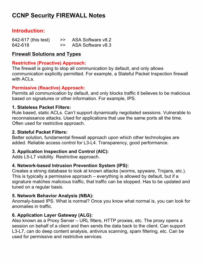
CCNP Security FIREWALL Notes Introduction: 642-617 (this test) >> ASA Software v8.2 642-618 >> ASA Software v8.3
Firewall Solutions and Types
Restrictive (Proactive) Approach: The firewall is going to stop all communication by default, and only allows communication explicitly permitted. For example, a Stateful Packet Inspection firewall with ACLs.
Permissive (Reactive) Approach: Permits all communication by default, and only blocks traffic it believes to be malicious based on signatures or other information. For example, IPS.
1. Stateless Packet Filters: Rule based, static ACLs. Can’t support dynamically negotiated sessions. Vulnerable to reconnaissance attacks. Used for applications that use the same ports all the time. Often used for restrictive approach.
2. Stateful Packet Filters: Better solution, fundamental firewall approach upon which other technologies are added. Reliable access control for L3-L4. Transparency, good performance.
3. Application Inspection and Control (AIC): Adds L5-L7 visibility. Restrictive approach.
4. Network-based Intrusion Prevention System (IPS): Creates a strong database to look at known attacks (worms, spyware, Trojans, etc.). This is typically a permissive approach – everything is allowed by default, but if a signature matches malicious traffic, that traffic can be stopped. Has to be updated and tuned on a regular basis.
5. Network Behavior Analysis (NBA): Anomaly-based IPS. What is normal? Once you know what normal is, you can look for anomalies in traffic.
6. Application Layer Gateway (ALG): Also known as a Proxy Server – URL filters, HTTP proxies, etc. The proxy opens a session on behalf of a client and then sends the data back to the client. Can support L3-L7, can do deep content analysis, antivirus scanning, spam filtering, etc. Can be used for permissive and restrictive services.
Initial Setup and Configuration
To enter rommon, use Break or ESC: Can perform password recovery and other functions including the ability to copy an image from a TFTP server – just like router or switch.
Entering rommon brings up the Management0/0 interface. Commonly used variables include: ADDRESS, GATEWAY, IMAGE, SERVER.
To change the Configuration Register, use confreg – just like router or switch.
To exit, use reboot, reload or reset.
To start the TFTP download: tftpdnld
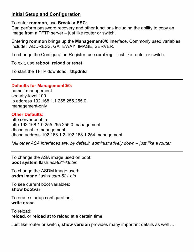
Defaults for Management0/0: nameif management security-level 100 ip address 192.168.1.1 255.255.255.0 management-only
Other Defaults: http server enable http 192.168.1.0 255.255.255.0 management dhcpd enable management dhcpd address 192.168.1.2-192.168.1.254 management
*All other ASA interfaces are, by default, administratively down – just like a router
To change the ASA image used on boot: boot system flash:asa821-k8.bin
To change the ASDM image used: asdm image flash:asdm-621.bin
To see current boot variables: show bootvar
To erase startup configuration: write erase
To reload: reload, or reload at to reload at a certain time
Just like router or switch, show version provides many important details as well …
To choose our inside interface: int e0/0 nameif inside
Default Security Levels:
Outside: 0 Inside: 100 DMZ: 50 (not really “default”, but commonly used)
0 à Lowest Trust 100 à Highest Trust 1-99 à Available for Assignment
By default, interfaces with the SAME security level can NOT exchange traffic – even with an ACL!
There is an option in ASDM called “Enable traffic between two or more interfaces which are configured with same security levels” to allow this …
CLI: same-security-traffic permit inter-interface
There is also another option called “Enable traffic between two or more hosts connected to the same interface” … if this device was a hub in a hub and spoke topology, traffic would enter an interface and be routed back out of the same interface.
CLI: same-security-traffic permit intra-interface
Traffic from a HIGHER security level to a LOWER security level is ALLOWED!
Example: traffic from INSIDE to OUTSIDE, traffic from DMZ to OUTSIDE
Traffic from a LOWER security level to a HIGHER security level is DENIED!
Example: traffic from OUTSIDE to INSIDE, or DMZ to INSIDE = NOT allowed
Jumbo Frame Support (frames > 1518 bytes): (config-if)# jumbo-frame reservation
Configuring VLANs via sub-interfaces example: … can also be done in ASDM by editing interface … First, prepare the physical interface before creating the sub-interfaces:
interface e0/0 no shutdown no nameif
interface e0/0.10 vlan 10 nameif SUB1 security-level 60 ip address 172.16.10.1 255.255.255.0
interface e0/0.20 vlan 20 nameif SUB2 security-level 60 ip address 172.16.20.1 255.255.255.0
End example
ASA Routing:
ASA’s support RIPv2, EIGRP, OSPF
To configure static routing (very popular in small deployments) go to: ASDM > Configuration > Device Setup > Routing > Static Routes
Simply enter 0.0.0.0 for the IP Address and Netmask fields to create a default static route …
DHCP Services:
ASDM > Configuration > Device Management > DHCP > DHCP Server
The rest is pretty self explanatory, just like any DHCP server setup …
ASA Management
This section covers very basic topics such as: hostname, domain name, DNS, enable password, host-address mappings (object), time, logging, files system, etc.
To configure DNS servers: ASDM > Configuration > Device Management > DNS > DNS Client
To create a host-address mapping (object): ASDM > Configuration > Firewall > Objects > Network Objects/Groups
To configure time / NTP: ASDM > Configuration > Device Setup > System Time > [Clock | NTP]
To configure Netflow collectors: ASDM > Configuration > Device Management > Logging > Netflow
To filter out certain types of logs: ASDM > Configuration > Device Management > Logging > Event List
To configure Syslog: ASDM > Configuration > Device Management > Logging > Syslog Servers Syslog Levels 7 >> 0 Debugging > Informational > Notifications > Warnings > Errors > Critical > Alerts > Emergencies
Use ASDM > Monitoring to see real-time logs
To manage the file system: ASDM > Tools Menu > File Management
CLI: show flash, dir flash:, dir /all, copy (disk0 == flash)
Upgrades:
Hint – upgrade ASDM first, then ASA …
To specify image boot order: ASDM > Device Management > System Image / Configuration > Boot
Licensing:
ASDM > Device Management > Licensing > Activation Key
Basic ASA Access Control
• Consider security policies such as least privilege, dual control, duty rotation • Use RBAC when possible
To generate RSA keys, it’s the same as a router or switch: crypto key generate rsa modulus 2048
To manage certificates in ASDM: ASDM > Configuration > Device Management > Certificate Management
To configure CLI banners: ASDM > Configuration > Device Management > Management Access > Command Line (CLI) > Banner
… ASDM, HTTPS, Telnet, SSH, SNMP also under Management Access
AAA is covered next. Self-explanatory: ASDM > Configuration > Device Management > Users/AAA
Modular Policy Framework (MPF) and Objects
ASA Tables (Databases):
v Translation Table (Xlate) Ø Shows NAT/PAT translations Ø IOS equivalent à show ip nat translations Ø NAT Control is mentioned here – it requires that packets traversing from an
inside interface to an outside interface match a NAT rule; for any host on the inside network to access a host on the outside network, you must configure NAT to translate the inside host address.
Ø show xlate [detail]
v Connection Table (Conn) Ø TCP/UDP/ICMP and other connections are tracked here Ø IOS equivalent à show ip nat translations verbose Ø show conn [detail]
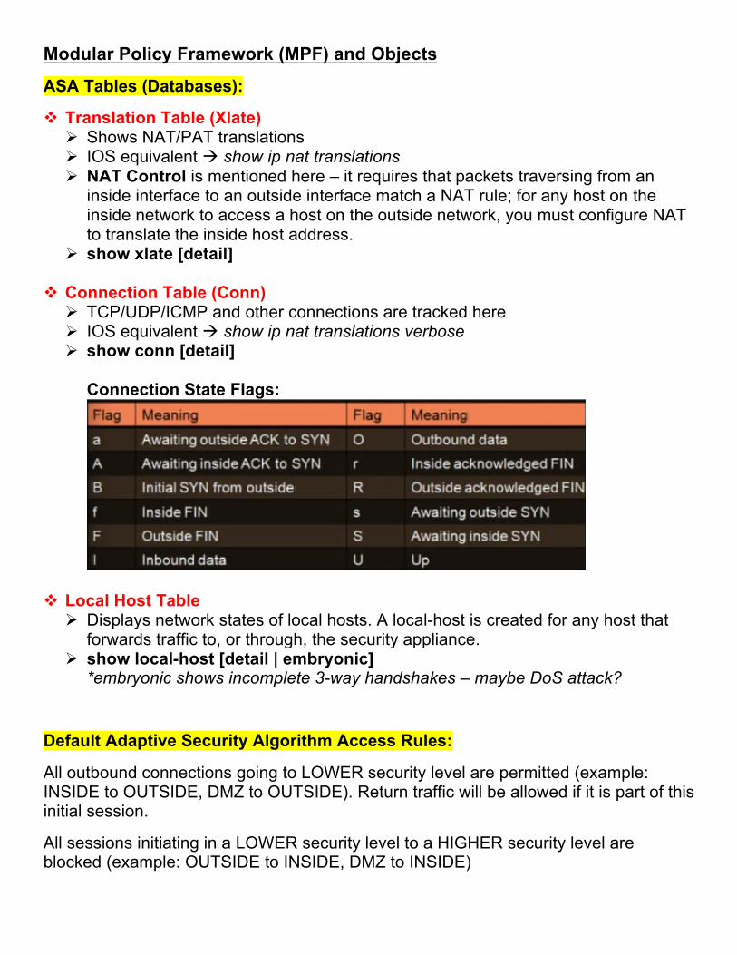
Connection State Flags:
v Local Host Table Ø Displays network states of local hosts. A local-host is created for any host that
forwards traffic to, or through, the security appliance. Ø show local-host [detail | embryonic]
*embryonic shows incomplete 3-way handshakes – maybe DoS attack?
Default Adaptive Security Algorithm Access Rules:
All outbound connections going to LOWER security level are permitted (example: INSIDE to OUTSIDE, DMZ to OUTSIDE). Return traffic will be allowed if it is part of this initial session.
All sessions initiating in a LOWER security level to a HIGHER security level are blocked (example: OUTSIDE to INSIDE, DMZ to INSIDE)
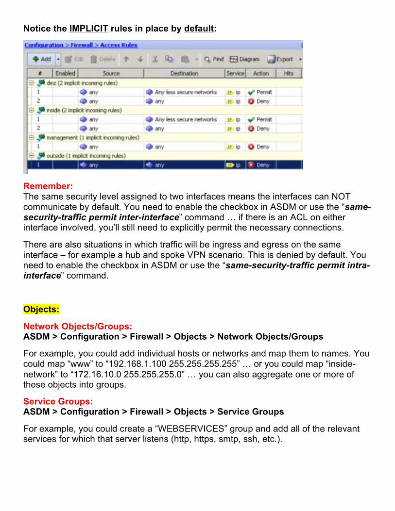
Notice the IMPLICIT rules in place by default:
Remember: The same security level assigned to two interfaces means the interfaces can NOT communicate by default. You need to enable the checkbox in ASDM or use the “same-security-traffic permit inter-interface” command … if there is an ACL on either interface involved, you’ll still need to explicitly permit the necessary connections.
There are also situations in which traffic will be ingress and egress on the same interface – for example a hub and spoke VPN scenario. This is denied by default. You need to enable the checkbox in ASDM or use the “same-security-traffic permit intra-interface” command.
Objects:
Network Objects/Groups: ASDM > Configuration > Firewall > Objects > Network Objects/Groups
For example, you could add individual hosts or networks and map them to names. You could map “www” to “192.168.1.100 255.255.255.255” … or you could map “inside-network” to “172.16.10.0 255.255.255.0” … you can also aggregate one or more of these objects into groups.
Service Groups: ASDM > Configuration > Firewall > Objects > Service Groups
For example, you could create a “WEBSERVICES” group and add all of the relevant services for which that server listens (http, https, smtp, ssh, etc.).
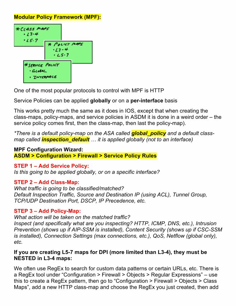
Modular Policy Framework (MPF):
One of the most popular protocols to control with MPF is HTTP
Service Policies can be applied globally or on a per-interface basis
This works pretty much the same as it does in IOS, except that when creating the class-maps, policy-maps, and service policies in ASDM it is done in a weird order – the service policy comes first, then the class-map, then last the policy-map).
*There is a default policy-map on the ASA called global_policy and a default class-map called inspection_default … it is applied globally (not to an interface)
MPF Configuration Wizard: ASDM > Configuration > Firewall > Service Policy Rules
STEP 1 – Add Service Policy: Is this going to be applied globally, or on a specific interface?
STEP 2 – Add Class-Map: What traffic is going to be classified/matched? Default Inspection Traffic, Source and Destination IP (using ACL), Tunnel Group, TCP/UDP Destination Port, DSCP, IP Precedence, etc.
STEP 3 – Add Policy-Map: What action will be taken on the matched traffic? Inspect (and specifically what are you inspecting? HTTP, ICMP, DNS, etc.), Intrusion Prevention (shows up if AIP-SSM is installed), Content Security (shows up if CSC-SSM is installed), Connection Settings (max connections, etc.), QoS, Netflow (global only), etc.
If you are creating L5-7 maps for DPI (more limited than L3-4), they must be NESTED in L3-4 maps:
We often use RegEx to search for custom data patterns or certain URLs, etc. There is a RegEx tool under “Configuration > Firewall > Objects > Regular Expressions” – use this to create a RegEx pattern, then go to “Configuration > Firewall > Objects > Class Maps”, add a new HTTP class-map and choose the RegEx you just created, then add
a new HTTP inspect-map under “Configuration > Firewall > Objects > Inspect Map”, URI filtering, match Regular Expressions, find the RegEx you created, and Drop / Log.
To apply it, create a new Service Policy as described above, but in the class-map section you will choose HTTP under protocol inspection, then use the HTTP inspect-map you just created.
Stateful Inspection
ASDM > Configuration > Firewall > Access Rules
To use MPF to control management traffic (traffic destined for the ASA itself): ASDM > Configuration > Firewall > Service Policy Rules … then choose “Add Management Service Policy Rule…”
ASAs, unlike an ISR, do not show up as a “hop” in traceroute – we have to explicitly make the ASA appear as such. TTL fields are not decremented as they traverse the device. To do this, add a “Service Policy Rule”, choose “Global”, choose “Any traffic”, then choose “Connection Settings”, then check the box under “Time to Live” that says “Decrement time to live for a connection” …
You can also tune the default IP Virtual Reassembly settings. To do this, go to “Advanced” under the Firewall configuration section, click “Fragment”, choose an interface and click edit, adjust as necessary …
To modify ASA TCP Normalizer features: ASDM > Configuration > Firewall > Objects > TCP Maps ... this can help you verify that your TCP sessions are adhering to the specifications of the protocol. We want to prevent malformed TCP packets from getting to a protected host.
We may also want to use this to create exceptions, like say for BGP traffic between two routers. The normalizer would break BGP authentication, so we need to create an exception to prevent this. In this case, we want to create a TCP Map to allow TCP Option 19, used by BGP for authentication. Add a Service Policy Rule, match a source/destination of any/any with a service of TCP/179 (BGP), go to “Connection Settings”, “TCP Normalization”, “Use TCP map”, then choose the map you just created.
There is also an option under “Advanced Options” to enable “TCP state bypass” to skip TCP state tracking and sequence checking when traffic flows across the ASA. It may be necessary to create such exceptions if applications are broken by the inspection behavior.
By default, “Randomize Sequence Number” is enabled on the ASA. This randomizes the sequence number of TCP/IP packets. It’s a countermeasure against injection attacks.
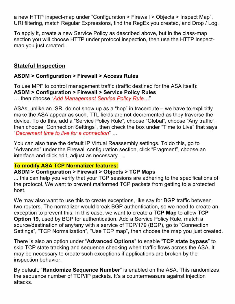
For servers using non-default ports, you can still enable inspection for those ports. For example, lets say we have an FTP server listening on port 2121 (instead of 21). We can create a new Service Policy Rule and tell it to match TCP/2121, then go to “Protocol Inspection” and choose the checkbox next to “FTP” …
Common Syslog Messages for Troubleshooting:
Application Layer Controls (L5-7 Inspection)
v Protocol Minimization Ø Only allow a certain group of protocol features to get through to the endpoint. We
want to minimize the Attack Surface. We can prevent both known and unknown attacks by blocking any traffic that’s not part of the minimum specification of the application.
v Payload Minimization Ø We are only going to allow a certain required set (a minimum level) of payload
through to the endpoint. This also prevents both known and unknown attacks. We are blocking any data that’s not part of a minimum specification policy.
v Application Layer Signatures Ø These are predefined patterns. We are looking for certain things inside of
application layer protocols and payloads. We are only preventing known attacks because of the signatures. This is a lot like an IPS. This can be done with an AIP-SSM ASA module or some other type of IPS module in an upstream device.
v Protocol Verification Ø The appliance drops packets that have non-standard protocol units in them. This
also prevents both known and unknown attacks. It can help prevent tunneling (or covert channeling) of other protocols inside of legitimate protocols. This is very common with port 80 (HTTP).
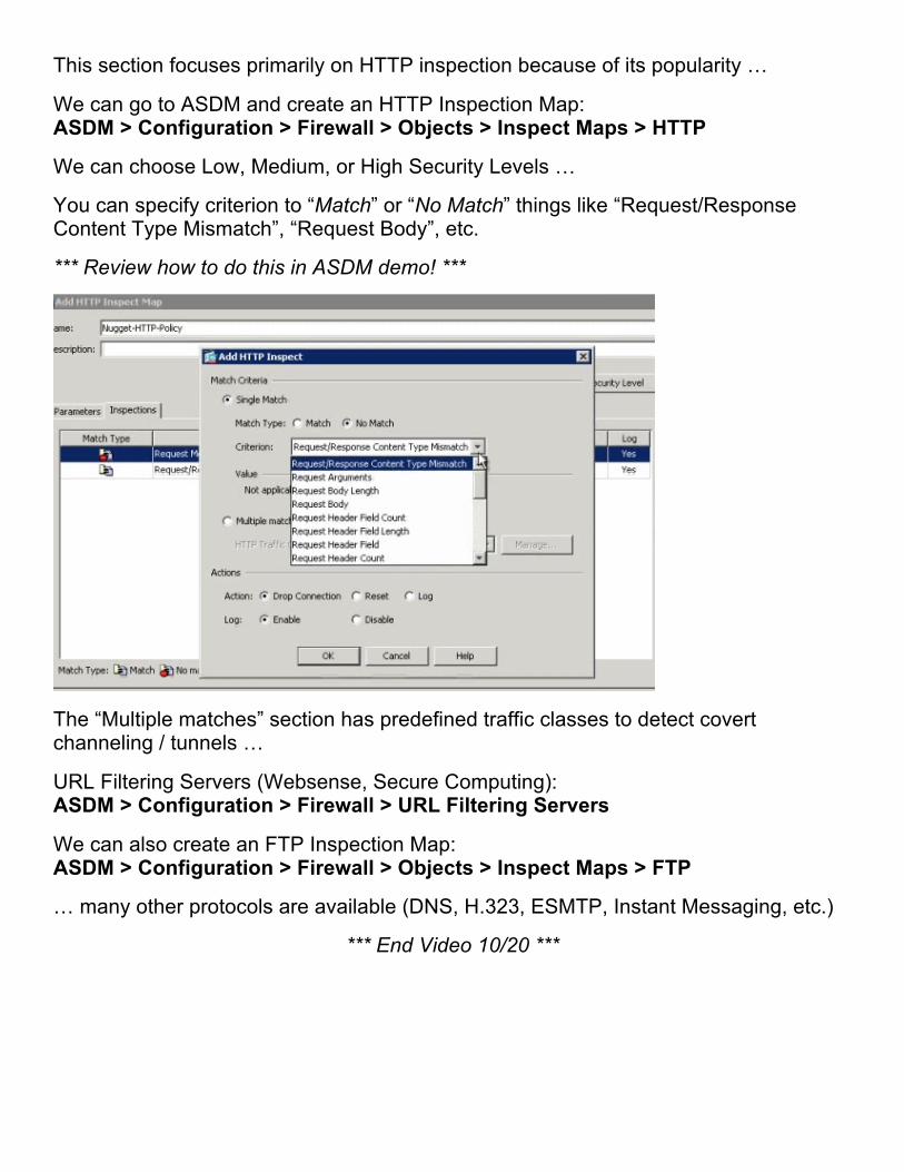
This section focuses primarily on HTTP inspection because of its popularity …
We can go to ASDM and create an HTTP Inspection Map: ASDM > Configuration > Firewall > Objects > Inspect Maps > HTTP
We can choose Low, Medium, or High Security Levels …
You can specify criterion to “Match” or “No Match” things like “Request/Response Content Type Mismatch”, “Request Body”, etc.
*** Review how to do this in ASDM demo! ***
The “Multiple matches” section has predefined traffic classes to detect covert channeling / tunnels …
URL Filtering Servers (Websense, Secure Computing): ASDM > Configuration > Firewall > URL Filtering Servers
We can also create an FTP Inspection Map: ASDM > Configuration > Firewall > Objects > Inspect Maps > FTP
… many other protocols are available (DNS, H.323, ESMTP, Instant Messaging, etc.)
*** End Video 10/20 ***
Advanced Access Controls
TCP Intercept:
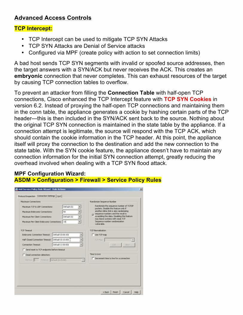
• TCP Intercept can be used to mitigate TCP SYN Attacks • TCP SYN Attacks are Denial of Service attacks • Configured via MPF (create policy with action to set connection limits)
A bad host sends TCP SYN segments with invalid or spoofed source addresses, then the target answers with a SYN/ACK but never receives the ACK. This creates an embryonic connection that never completes. This can exhaust resources of the target by causing TCP connection tables to overflow.
To prevent an attacker from filling the Connection Table with half-open TCP connections, Cisco enhanced the TCP Intercept feature with TCP SYN Cookies in version 6.2. Instead of proxying the half-open TCP connections and maintaining them in the conn table, the appliance generates a cookie by hashing certain parts of the TCP header—this is then included in the SYN/ACK sent back to the source. Nothing about the original TCP SYN connection is maintained in the state table by the appliance. If a connection attempt is legitimate, the source will respond with the TCP ACK, which should contain the cookie information in the TCP header. At this point, the appliance itself will proxy the connection to the destination and add the new connection to the state table. With the SYN cookie feature, the appliance doesn’t have to maintain any connection information for the initial SYN connection attempt, greatly reducing the overhead involved when dealing with a TCP SYN flood attack.
MPF Configuration Wizard: ASDM > Configuration > Firewall > Service Policy Rules
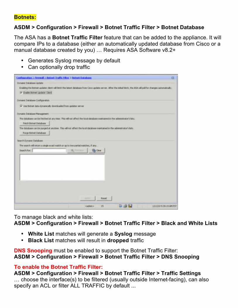
Botnets:
ASDM > Configuration > Firewall > Botnet Traffic Filter > Botnet Database
The ASA has a Botnet Traffic Filter feature that can be added to the appliance. It will compare IPs to a database (either an automatically updated database from Cisco or a manual database created by you) … Requires ASA Software v8.2+
• Generates Syslog message by default • Can optionally drop traffic
To manage black and white lists: ASDM > Configuration > Firewall > Botnet Traffic Filter > Black and White Lists
• White List matches will generate a Syslog message • Black List matches will result in dropped traffic
DNS Snooping must be enabled to support the Botnet Traffic Filter: ASDM > Configuration > Firewall > Botnet Traffic Filter > DNS Snooping
To enable the Botnet Traffic Filter: ASDM > Configuration > Firewall > Botnet Traffic Filter > Traffic Settings … choose the interface(s) to be filtered (usually outside Internet-facing), can also specify an ACL or filter ALL TRAFFIC by default ...
This section is also used to define Blacklisted Traffic Actions. You can specify interfaces/actions and threat levels (Very Low, Low, Medium, High, Very High) … again an ACL can be specified here to define traffic to be dropped.
Botnet Traffic Filter CLI commands: dynamic-filter xxx dynamic-filter enable interface outside
Threat Detection:
Basic Threat Detection is enabled by default on the ASA: ASDM > Configuration > Firewall > Threat Detection
It monitors the rate of dropped packets on the appliance, security events per second, etc. and generates a Syslog message (733100) when a certain threshold has been reached. This is kind of like “IDS Junior.”
Basic Threat Detection CLI command: threat-detection basic-threat
Scanning Threat Detection is NOT enabled by default on the ASA. It is more CPU intensive than Basic Threat Detection. This will detect hosts that are scanning or sweeping the network and generate a Syslog message (733101). You can enable “Shun hosts detected by scanning threat” and then specify a shun duration in seconds (default is 3600). You can also exclude certain networks from the shun (e.g. management networks, etc.).
Scanning Threat Detection CLI command: threat-detection scanning-threat
Scanning Threat Statistics can also be enabled. You can “Enable all statistics” or “Enable only following statistics: Host, Access rules, Port, Protocol, TCP Intercept” … you can also specify rate intervals for the statistics collection.
TCP Intercept Threat Detection is another option within this section. You can use it to tune rate thresholds such as “Monitoring Window Size”, “Burst Threshold Rate” and “Average Threshold Rate” …
Show commands: show threat-detection statistics host show threat-detection statistics top tcp-intercept
Resource Configuration
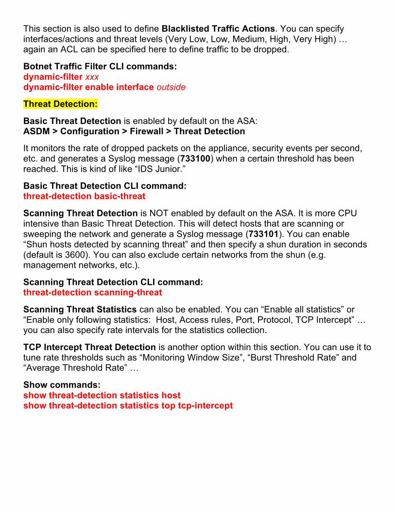
Configuring Connection Limits:
This works like any other MPF (Modular Policy Framework) configuration: ASDM > Configuration > Firewall > Service Policy Rules
1. Configure a service policy For example, we will choose the DMZ interface and call this “TRAFFIC_TO_DMZ”
2. Configure the class-map For example, we will call this “TRAFFIC_TO_DMZ_CLASS” and choose “Source and Destination IP Address (uses ACL)” … source “any” and destination “the DMZ network’s subnet” with a service of “ip” … we can use “More Options” to specify a “Time Range” if necessary
3. Configure the policy-map Choose the “Connection Settings” tab and specify: Maximum TCP & UDP Connections (really TCP connections, UDP flows) Maximum Embryonic Connections Maximum Per Client Connections Maximum Per Client Embryonic Connections CLI: set connection conn-max x per-client-max x
Traffic Policing vs. Traffic Shaping:
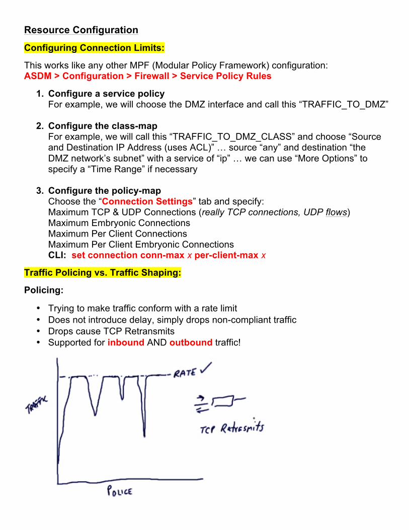
Policing:
• Trying to make traffic conform with a rate limit • Does not introduce delay, simply drops non-compliant traffic • Drops cause TCP Retransmits • Supported for inbound AND outbound traffic!
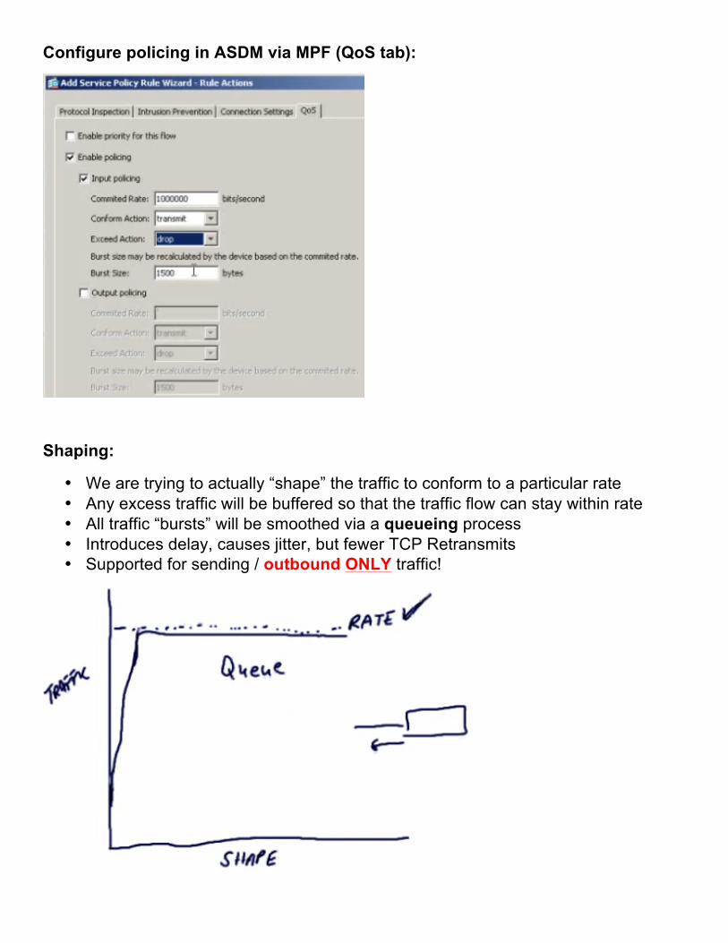
Configure policing in ASDM via MPF (QoS tab):
Shaping:
• We are trying to actually “shape” the traffic to conform to a particular rate • Any excess traffic will be buffered so that the traffic flow can stay within rate • All traffic “bursts” will be smoothed via a queueing process • Introduces delay, causes jitter, but fewer TCP Retransmits • Supported for sending / outbound ONLY traffic!
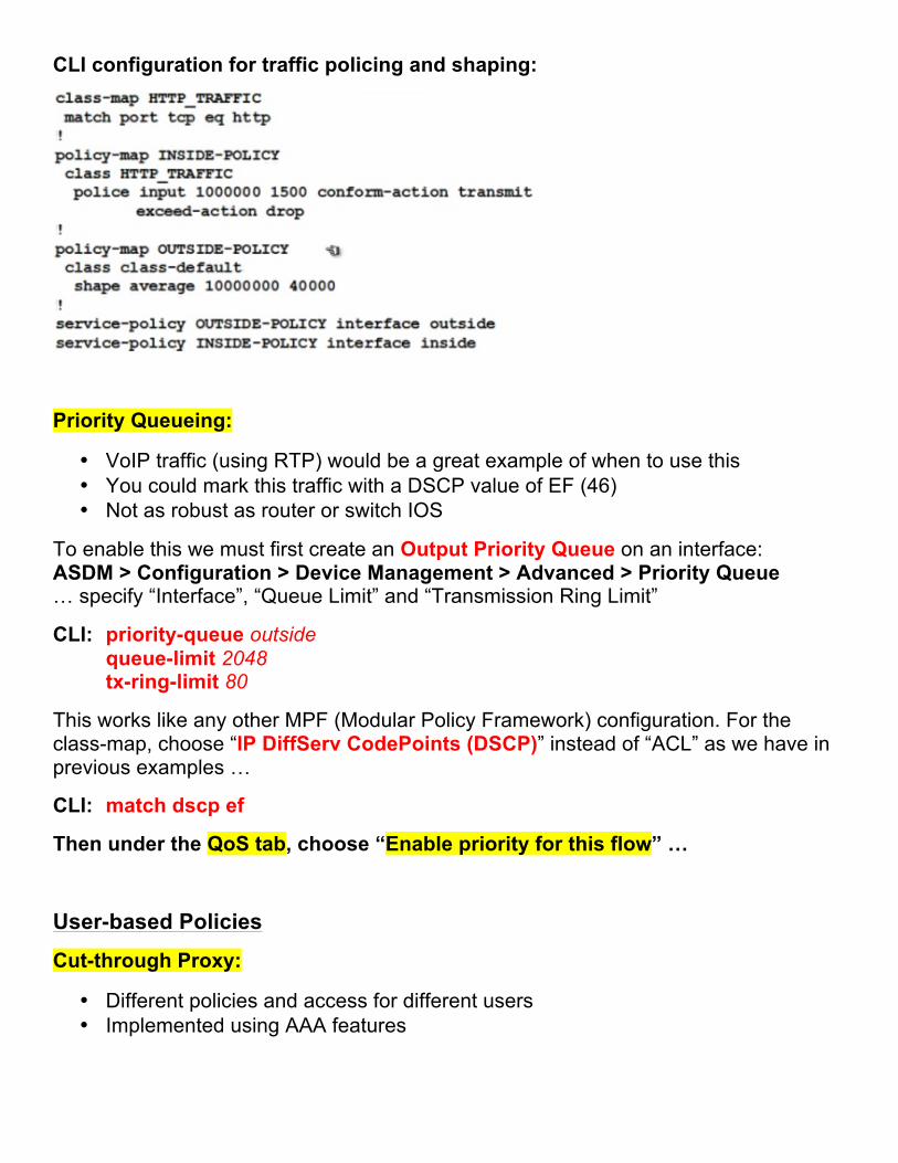
CLI configuration for traffic policing and shaping:
Priority Queueing:
• VoIP traffic (using RTP) would be a great example of when to use this • You could mark this traffic with a DSCP value of EF (46) • Not as robust as router or switch IOS
To enable this we must first create an Output Priority Queue on an interface: ASDM > Configuration > Device Management > Advanced > Priority Queue … specify “Interface”, “Queue Limit” and “Transmission Ring Limit”
CLI: priority-queue outside queue-limit 2048 tx-ring-limit 80
This works like any other MPF (Modular Policy Framework) configuration. For the class-map, choose “IP DiffServ CodePoints (DSCP)” instead of “ACL” as we have in previous examples …
CLI: match dscp ef
Then under the QoS tab, choose “Enable priority for this flow” …
User-based Policies
Cut-through Proxy:
• Different policies and access for different users • Implemented using AAA features
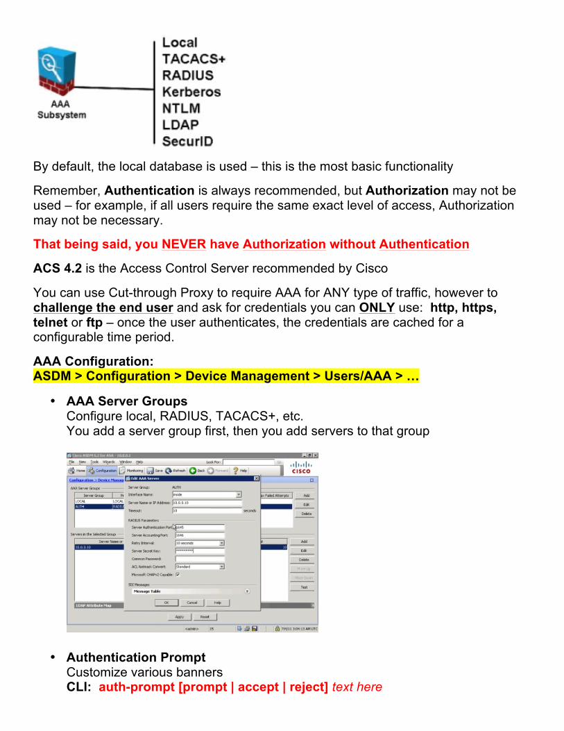
By default, the local database is used – this is the most basic functionality
Remember, Authentication is always recommended, but Authorization may not be used – for example, if all users require the same exact level of access, Authorization may not be necessary.
That being said, you NEVER have Authorization without Authentication
ACS 4.2 is the Access Control Server recommended by Cisco
You can use Cut-through Proxy to require AAA for ANY type of traffic, however to challenge the end user and ask for credentials you can ONLY use: http, https, telnet or ftp – once the user authenticates, the credentials are cached for a configurable time period.
AAA Configuration: ASDM > Configuration > Device Management > Users/AAA > …
• AAA Server Groups Configure local, RADIUS, TACACS+, etc. You add a server group first, then you add servers to that group
• Authentication Prompt Customize various banners CLI: auth-prompt [prompt | accept | reject] text here
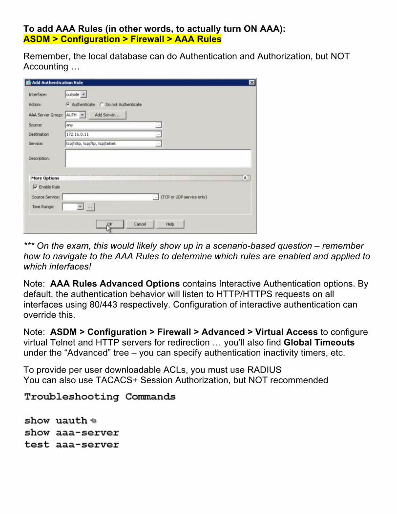
To add AAA Rules (in other words, to actually turn ON AAA): ASDM > Configuration > Firewall > AAA Rules
Remember, the local database can do Authentication and Authorization, but NOT Accounting …
*** On the exam, this would likely show up in a scenario-based question – remember how to navigate to the AAA Rules to determine which rules are enabled and applied to which interfaces!
Note: AAA Rules Advanced Options contains Interactive Authentication options. By default, the authentication behavior will listen to HTTP/HTTPS requests on all interfaces using 80/443 respectively. Configuration of interactive authentication can override this.
Note: ASDM > Configuration > Firewall > Advanced > Virtual Access to configure virtual Telnet and HTTP servers for redirection … you’ll also find Global Timeouts under the “Advanced” tree – you can specify authentication inactivity timers, etc.
To provide per user downloadable ACLs, you must use RADIUS You can also use TACACS+ Session Authorization, but NOT recommended
NAT / PAT
This section starts off with a simple review of NAT. The test primarily focuses on inside NAT, but outside NAT is mentioned. A typical scenario for the use of outside NAT would be to resolve conflicting address space if one company acquired another company, and the acquired company was using the same internal address space.
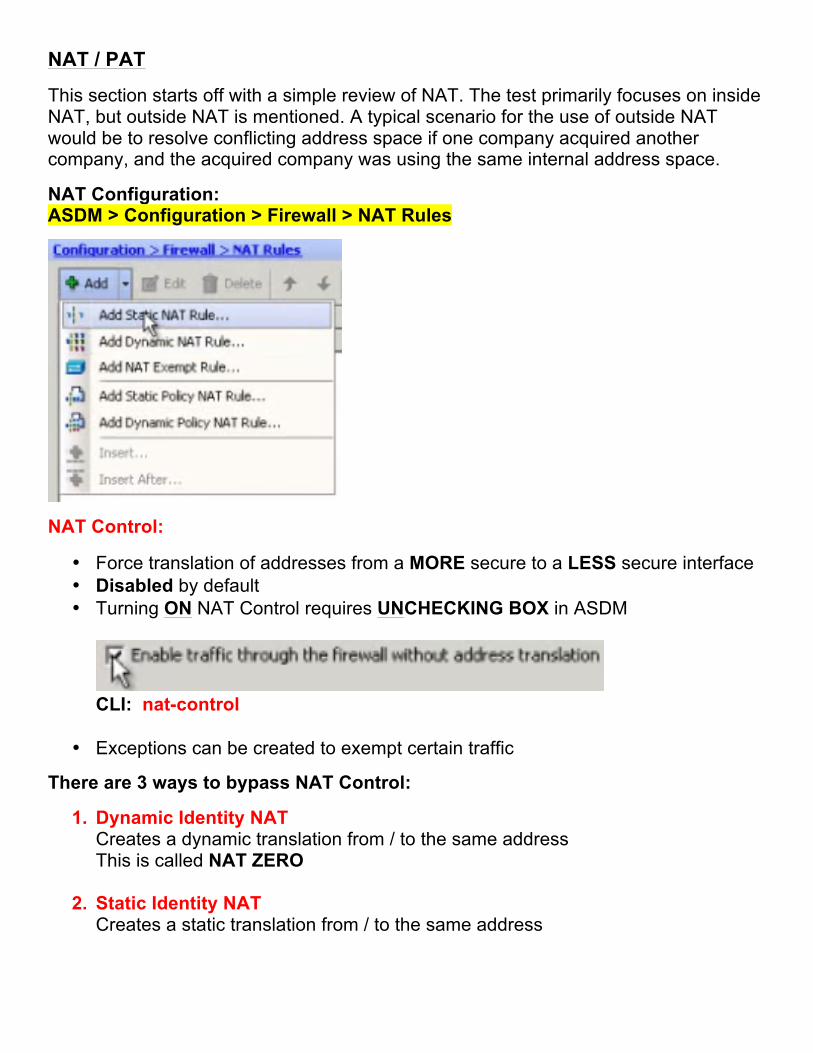
NAT Configuration: ASDM > Configuration > Firewall > NAT Rules
NAT Control:
• Force translation of addresses from a MORE secure to a LESS secure interface • Disabled by default • Turning ON NAT Control requires UNCHECKING BOX in ASDM
CLI: nat-control
• Exceptions can be created to exempt certain traffic
There are 3 ways to bypass NAT Control:
1. Dynamic Identity NAT Creates a dynamic translation from / to the same address This is called NAT ZERO
2. Static Identity NAT Creates a static translation from / to the same address
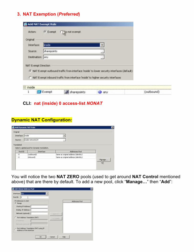
3. NAT Exemption (Preferred)
CLI: nat (inside) 0 access-list NONAT
Dynamic NAT Configuration:
You will notice the two NAT ZERO pools (used to get around NAT Control mentioned above) that are there by default. To add a new pool, click “Manage…” then “Add”:
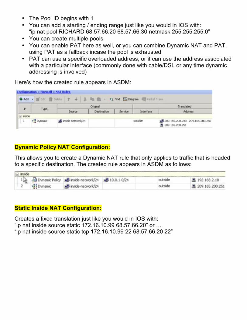
• The Pool ID begins with 1 • You can add a starting / ending range just like you would in IOS with:
“ip nat pool RICHARD 68.57.66.20 68.57.66.30 netmask 255.255.255.0” • You can create multiple pools • You can enable PAT here as well, or you can combine Dynamic NAT and PAT,
using PAT as a fallback incase the pool is exhausted • PAT can use a specific overloaded address, or it can use the address associated
with a particular interface (commonly done with cable/DSL or any time dynamic addressing is involved)
Here’s how the created rule appears in ASDM:
Dynamic Policy NAT Configuration:
This allows you to create a Dynamic NAT rule that only applies to traffic that is headed to a specific destination. The created rule appears in ASDM as follows:
Static Inside NAT Configuration:
Creates a fixed translation just like you would in IOS with: “ip nat inside source static 172.16.10.99 68.57.66.20” or … “ip nat inside source static tcp 172.16.10.99 22 68.57.66.20 22”
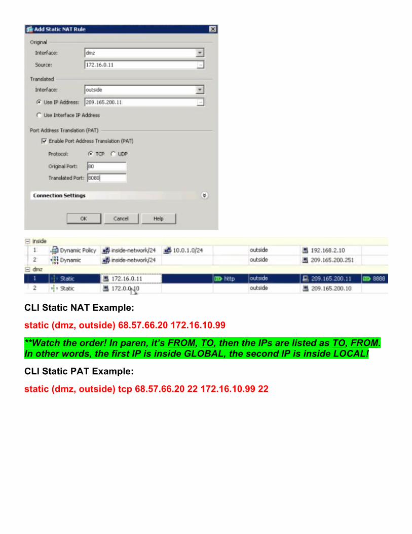
CLI Static NAT Example:
static (dmz, outside) 68.57.66.20 172.16.10.99
**Watch the order! In paren, it’s FROM, TO, then the IPs are listed as TO, FROM. In other words, the first IP is inside GLOBAL, the second IP is inside LOCAL!
CLI Static PAT Example:
static (dmz, outside) tcp 68.57.66.20 22 172.16.10.99 22
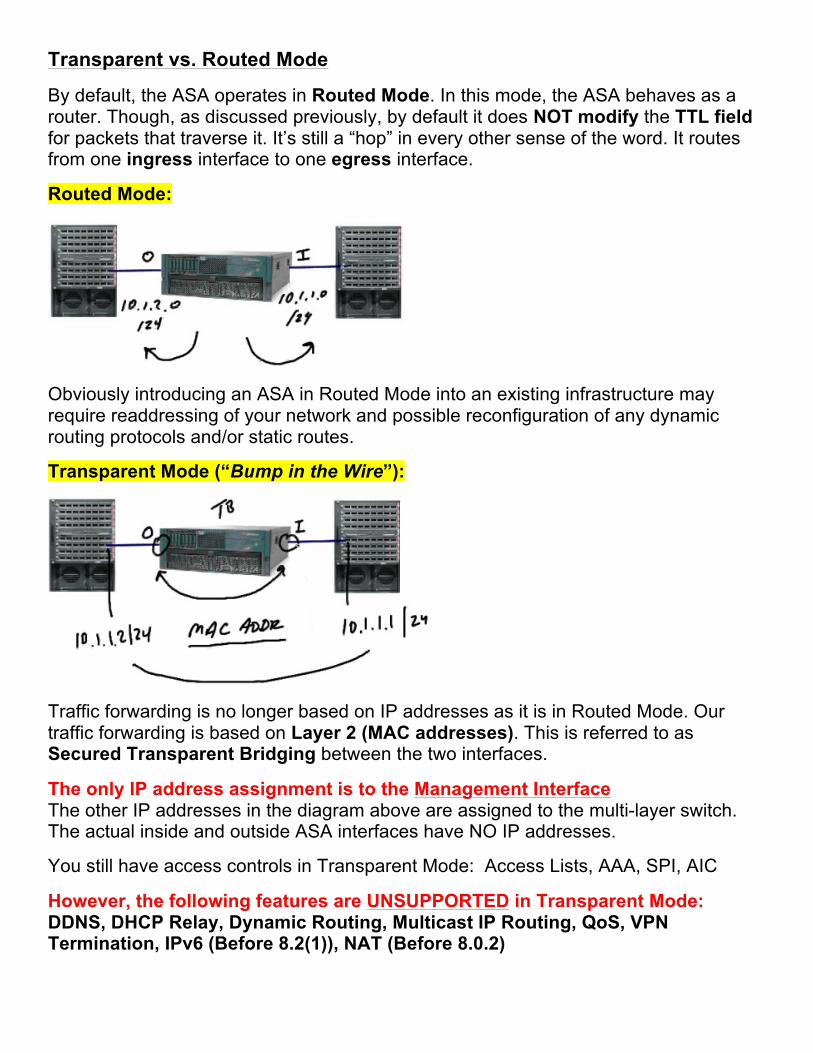
Transparent vs. Routed Mode
By default, the ASA operates in Routed Mode. In this mode, the ASA behaves as a router. Though, as discussed previously, by default it does NOT modify the TTL field for packets that traverse it. It’s still a “hop” in every other sense of the word. It routes from one ingress interface to one egress interface.
Routed Mode:
Obviously introducing an ASA in Routed Mode into an existing infrastructure may require readdressing of your network and possible reconfiguration of any dynamic routing protocols and/or static routes.
Transparent Mode (“Bump in the Wire”):
Traffic forwarding is no longer based on IP addresses as it is in Routed Mode. Our traffic forwarding is based on Layer 2 (MAC addresses). This is referred to as Secured Transparent Bridging between the two interfaces.
The only IP address assignment is to the Management Interface The other IP addresses in the diagram above are assigned to the multi-layer switch. The actual inside and outside ASA interfaces have NO IP addresses.
You still have access controls in Transparent Mode: Access Lists, AAA, SPI, AIC
However, the following features are UNSUPPORTED in Transparent Mode: DDNS, DHCP Relay, Dynamic Routing, Multicast IP Routing, QoS, VPN Termination, IPv6 (Before 8.2(1)), NAT (Before 8.0.2)
… there is no inspection of the L3 header, so you can see why QoS and other features would be unsupported in Transparent Mode.
Switching between Routed Mode and Transparent Mode:
firewall transparent << Switch to Transparent Mode no firewall transparent << Switch to Routed Mode show firewall << Show command for verification show int ip bri << Show interfaces and IP addresses ^^^^^ watch this – it’s backwards from the IOS command “show ip int bri”
Sample Configuration:
int eth 0/0 nameif inside security-level xxx (default is 100) no shut
int eth 0/1 nameif outside security-level xxx (default is 0) no shut
à NO IP addresses are assigned to these interfaces – only management interface!
domain-name nuggetlab.com ip address 10.0.1.1 255.255.255.0 << issued in GLOBAL config mode, assigns IP to management interface
http server enable http 10.0.1.10 255.255.255.255 inside
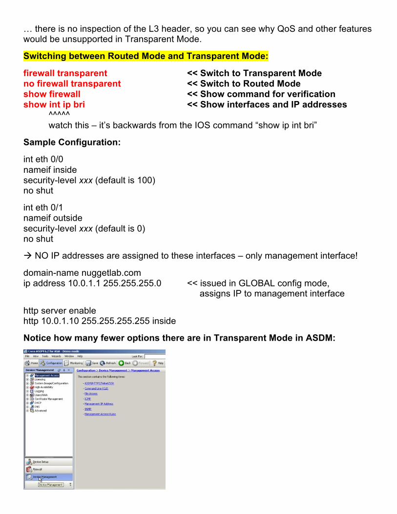
Notice how many fewer options there are in Transparent Mode in ASDM:
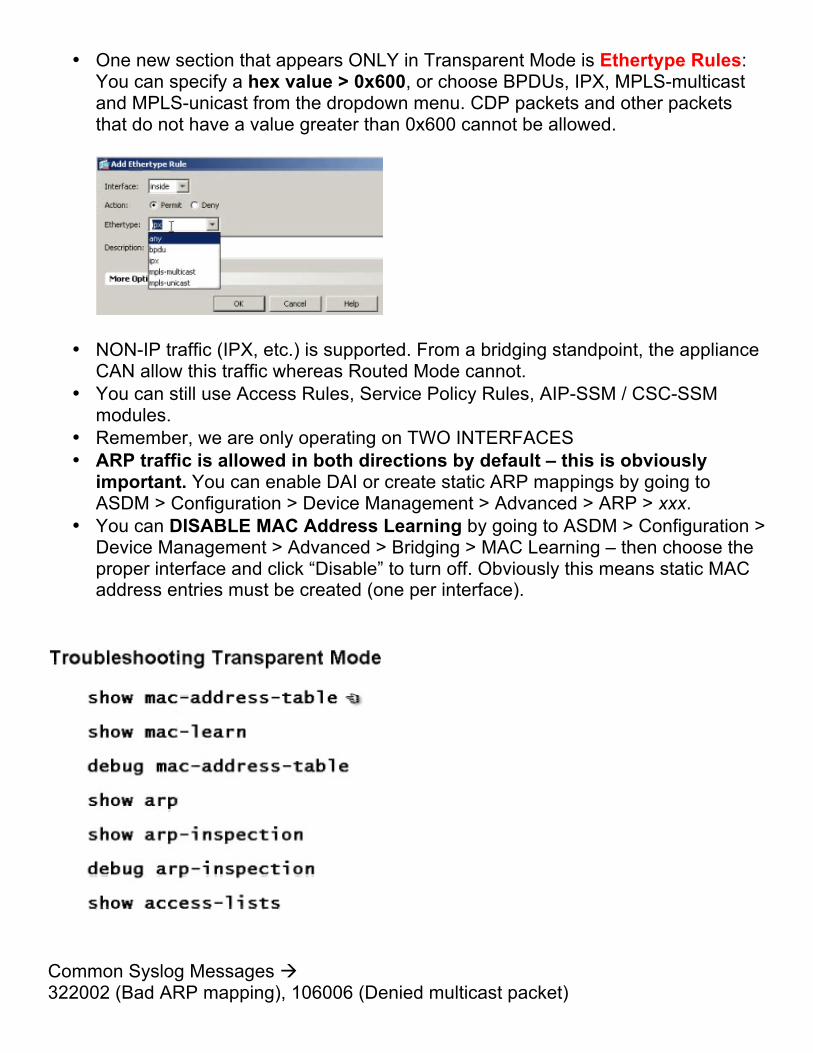
• One new section that appears ONLY in Transparent Mode is Ethertype Rules: You can specify a hex value > 0x600, or choose BPDUs, IPX, MPLS-multicast and MPLS-unicast from the dropdown menu. CDP packets and other packets that do not have a value greater than 0x600 cannot be allowed.
• NON-IP traffic (IPX, etc.) is supported. From a bridging standpoint, the appliance CAN allow this traffic whereas Routed Mode cannot.
• You can still use Access Rules, Service Policy Rules, AIP-SSM / CSC-SSM modules.
• Remember, we are only operating on TWO INTERFACES • ARP traffic is allowed in both directions by default – this is obviously
important. You can enable DAI or create static ARP mappings by going to ASDM > Configuration > Device Management > Advanced > ARP > xxx.
• You can DISABLE MAC Address Learning by going to ASDM > Configuration > Device Management > Advanced > Bridging > MAC Learning – then choose the proper interface and click “Disable” to turn off. Obviously this means static MAC address entries must be created (one per interface).
Common Syslog Messages à 322002 (Bad ARP mapping), 106006 (Denied multicast packet)
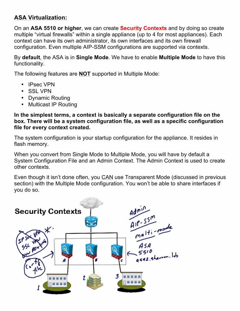
ASA Virtualization:
On an ASA 5510 or higher, we can create Security Contexts and by doing so create multiple “virtual firewalls” within a single appliance (up to 4 for most appliances). Each context can have its own administrator, its own interfaces and its own firewall configuration. Even multiple AIP-SSM configurations are supported via contexts.
By default, the ASA is in Single Mode. We have to enable Multiple Mode to have this functionality.
The following features are NOT supported in Multiple Mode:
• IPsec VPN • SSL VPN • Dynamic Routing • Multicast IP Routing
In the simplest terms, a context is basically a separate configuration file on the box. There will be a system configuration file, as well as a specific configuration file for every context created.
The system configuration is your startup configuration for the appliance. It resides in flash memory.
When you convert from Single Mode to Multiple Mode, you will have by default a System Configuration File and an Admin Context. The Admin Context is used to create other contexts.
Even though it isn’t done often, you CAN use Transparent Mode (discussed in previous section) with the Multiple Mode configuration. You won’t be able to share interfaces if you do so.
Switching between Single Mode and Multiple Mode:
mode multiple << Switch to Multiple Mode* mode single << Switch to Single Mode*
*Reboot required!
If you look in flash (“dir flash” or “show flash”) after switching to Multiple Mode, you will see two new files:
• old_running.cfg << Backup of the previous running configuration • admin.cfg << The default admin context configuration file
The admin context has to be stored in internal flash, but when you create new contexts they can be stored in flash or elsewhere (http, ftp, tftp, etc.).
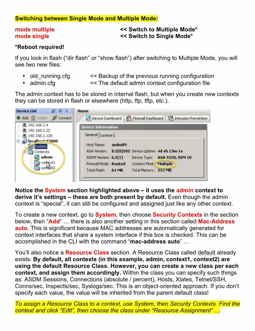
Notice the System section highlighted above – it uses the admin context to derive it’s settings – these are both present by default. Even though the admin context is “special”, it can still be configured and assigned just like any other context.
To create a new context, go to System, then choose Security Contexts in the section below, then “Add” … there is also another setting in this section called Mac-Address auto. This is significant because MAC addresses are automatically generated for context interfaces that share a system interface if this box is checked. This can be accomplished in the CLI with the command “mac-address auto” …
You’ll also notice a Resource Class section. A Resource Class called default already exists. By default, all contexts (in this example, admin, context1, context2) are using the default Resource Class. However, you can create a new class per each context, and assign them accordingly. Within the class you can specify such things as: ASDM Sessions, Connections (absolute / percent), Hosts, Xlates, Telnet/SSH, Conns/sec, Inspects/sec, Syslogs/sec. This is an object-oriented approach. If you don’t specify each value, the value will be inherited from the parent default class!
To assign a Resource Class to a context, use System, then Security Contexts. Find the context and click “Edit”, then choose the class under “Resource Assignment” …
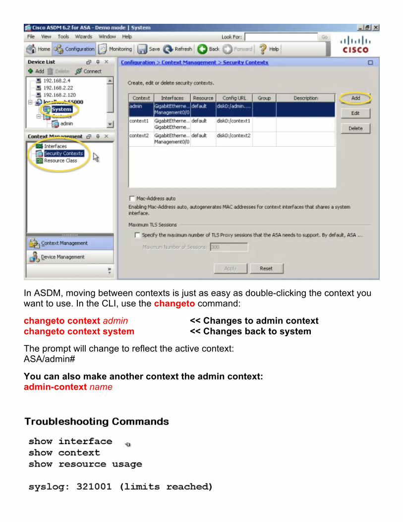
In ASDM, moving between contexts is just as easy as double-clicking the context you want to use. In the CLI, use the changeto command:
changeto context admin << Changes to admin context changeto context system << Changes back to system
The prompt will change to reflect the active context: ASA/admin#
You can also make another context the admin context: admin-context name
Active/Standby Failover:
Active/Standby Failover is one of two failover modes available on the ASA, the other being Active/Active Failover.
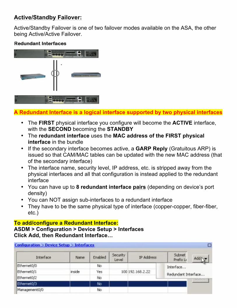
A Redundant Interface is a logical interface supported by two physical interfaces
• The FIRST physical interface you configure will become the ACTIVE interface, with the SECOND becoming the STANDBY
• The redundant interface uses the MAC address of the FIRST physical interface in the bundle
• If the secondary interface becomes active, a GARP Reply (Gratuitous ARP) is issued so that CAM/MAC tables can be updated with the new MAC address (that of the secondary interface)
• The interface name, security level, IP address, etc. is stripped away from the physical interfaces and all that configuration is instead applied to the redundant interface
• You can have up to 8 redundant interface pairs (depending on device’s port density)
• You can NOT assign sub-interfaces to a redundant interface • They have to be the same physical type of interface (copper-copper, fiber-fiber,
etc.)
To add/configure a Redundant Interface: ASDM > Configuration > Device Setup > Interfaces Click Add, then Redundant Interface…
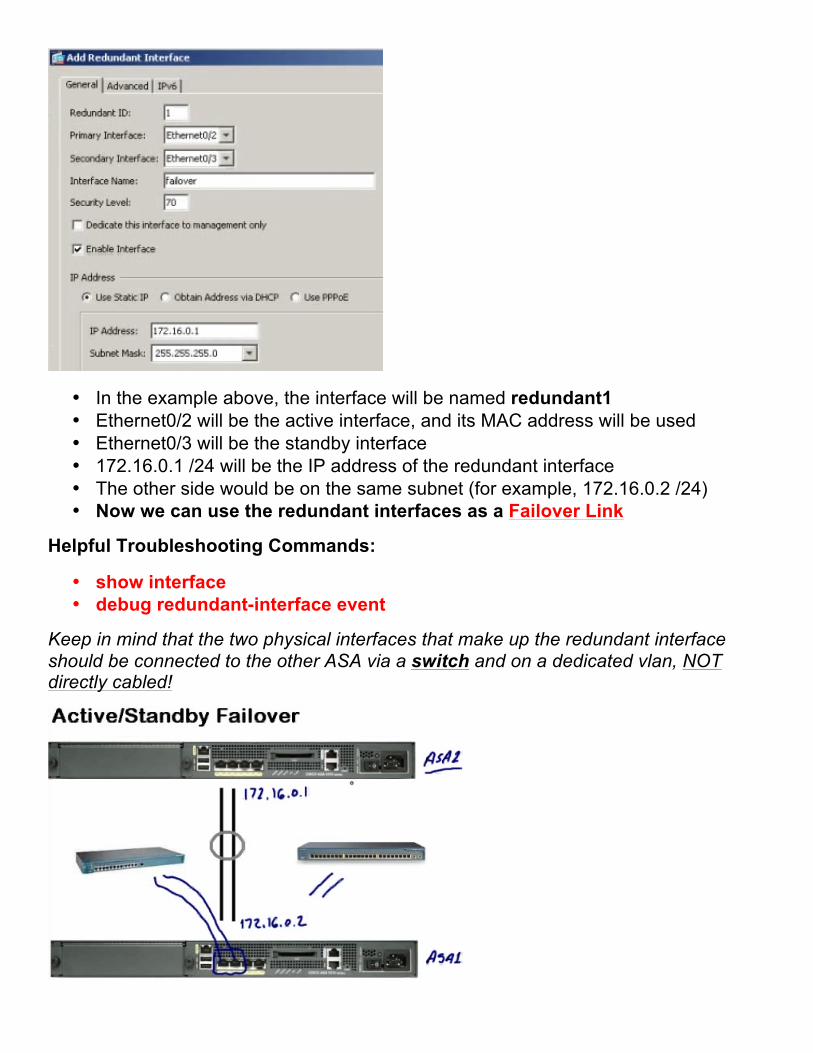
• In the example above, the interface will be named redundant1 • Ethernet0/2 will be the active interface, and its MAC address will be used • Ethernet0/3 will be the standby interface • 172.16.0.1 /24 will be the IP address of the redundant interface • The other side would be on the same subnet (for example, 172.16.0.2 /24) • Now we can use the redundant interfaces as a Failover Link
Helpful Troubleshooting Commands:
• show interface • debug redundant-interface event
Keep in mind that the two physical interfaces that make up the redundant interface should be connected to the other ASA via a switch and on a dedicated vlan, NOT directly cabled!
In the event the active device fails:
• The standby device will become active and a switchover will occur • The standby device will assume the identity of the active device, which
includes the IP and MAC addresses of the previously active device on ALL interfaces except the failover interfaces – those addresses will remain the same
• The roles of primary and secondary device don’t change – but in this scenario the primary device is now standby and the secondary device is active.
How it works:
• Both devices are managed as a single device/unit • All configuration is performed from the active unit • The configuration is automatically replicated to the standby device via the failover
link • Stateless Failover and Stateful Failover is available • Obviously with Stateless, all active connections will be dropped • With Stateful, the connections will be moved to the other ASA • Stateful requires more port density – ideally a redundant pair, but at least one
interface that can carry the state information (a Stateful Link) • You CAN use the Failover Link as a Stateful Link too if necessary
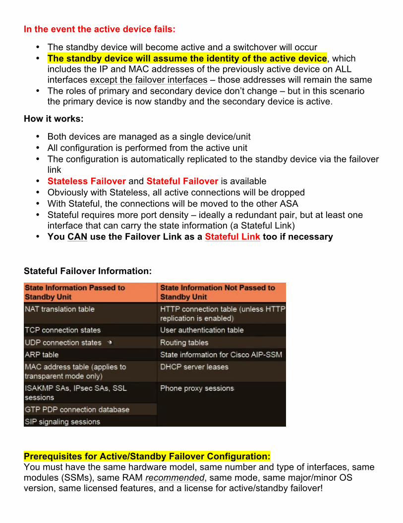
Stateful Failover Information:
Prerequisites for Active/Standby Failover Configuration: You must have the same hardware model, same number and type of interfaces, same modules (SSMs), same RAM recommended, same mode, same major/minor OS version, same licensed features, and a license for active/standby failover!
Configuring Active/Standby Failover:
ASDM > Wizards > High Availability and Scalability Wizard -- or -- ASDM > Configuration > Device Management > High Availability
Step 1: Choose Active/Active failover or Active/Standby failover
Step 2: Specify the Peer IP Address (NOT the failover IP) *During this step, the prerequisites mentioned above will be verified
Step 3: Specify LAN Link (Failover Link) (example, “redundant1”) Logical Name (example, “FAILOVER”) Active IP Address (example, “172.16.0.1”) Standby IP Address (example, “172.16.0.2”) Subnet Mask (example, “255.255.255.252”) Optional Encryption Key
Step 4: Stateful Failover? You can disable, use LAN Link as Stateful Link, or use separate interface If you disable, you have HARDWARE FAILOVER only!
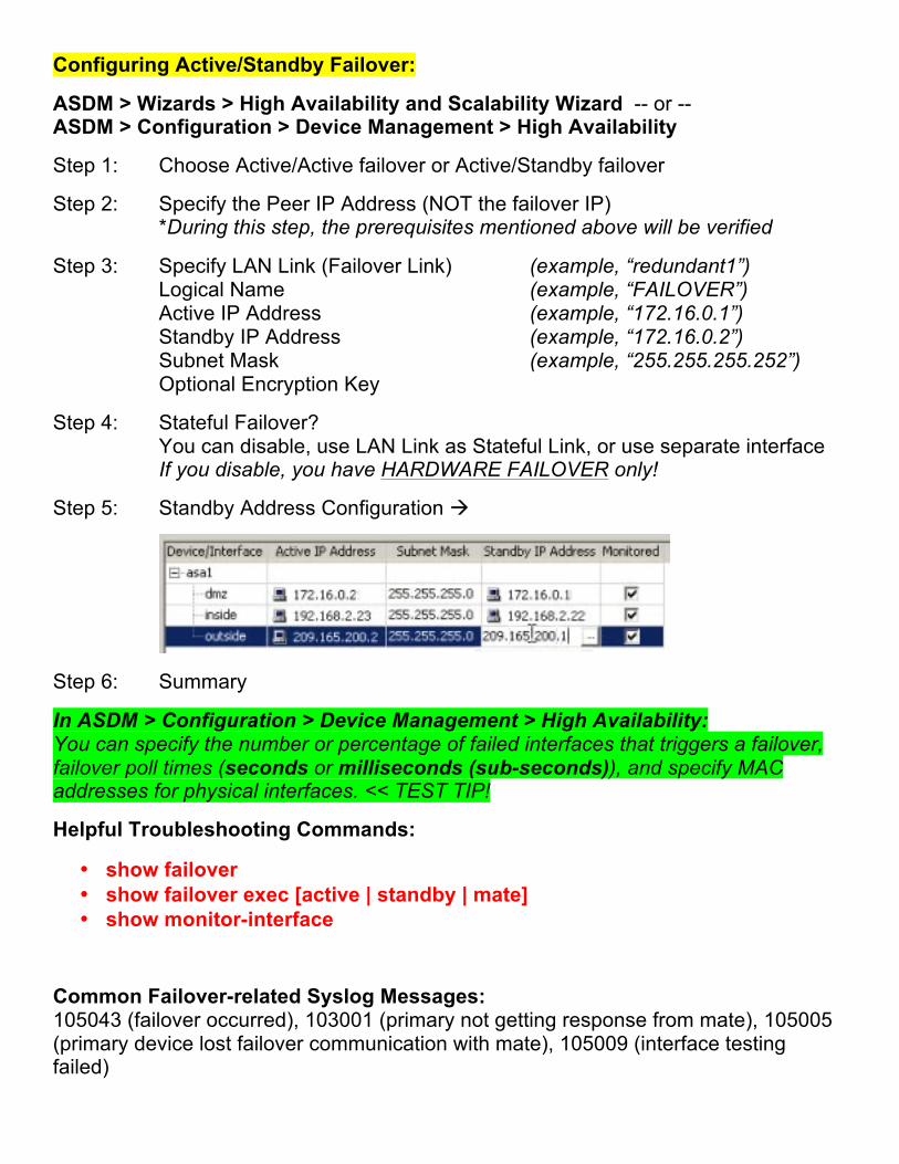
Step 5: Standby Address Configuration à
Step 6: Summary
In ASDM > Configuration > Device Management > High Availability: You can specify the number or percentage of failed interfaces that triggers a failover, failover poll times (seconds or milliseconds (sub-seconds)), and specify MAC addresses for physical interfaces. << TEST TIP!
Helpful Troubleshooting Commands:
• show failover • show failover exec [active | standby | mate] • show monitor-interface
Common Failover-related Syslog Messages: 105043 (failover occurred), 103001 (primary not getting response from mate), 105005 (primary device lost failover communication with mate), 105009 (interface testing failed)
Active/Active Failover:
• Requires minimum of ASA 5510 w/ Security Plus License (NOT Base) • Requires device to be in Multiple Mode (NOT Single Mode) • Requires security contexts (thus the requirement for Multiple Mode) • Both ASAs are passing traffic simultaneously • We still have redundancy as with Active/Standby, but also load balancing
To configure, use the same High Availability and Scalability Wizard used to configure Active/Standby Failover.
For example, we could have two contexts on each ASA, each protecting DIFFERENT traffic. For example, one context could protect Internet traffic, while the other protects datacenter traffic.
If you have two or more contexts that supported the SAME traffic (e.g. both protecting Internet traffic), the configuration becomes much more complex. This involves ECLB (Equal Cost Load Balancing) and PBR (Policy Based Routing).
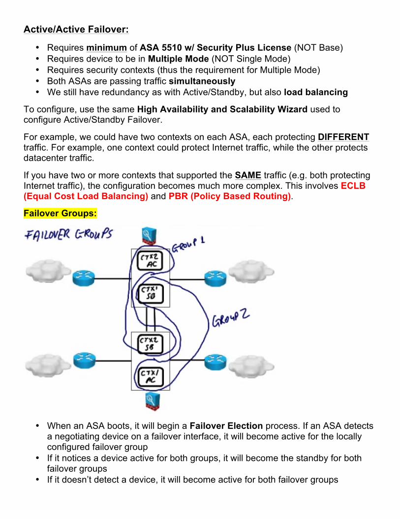
Failover Groups:
• When an ASA boots, it will begin a Failover Election process. If an ASA detects a negotiating device on a failover interface, it will become active for the locally configured failover group
• If it notices a device active for both groups, it will become the standby for both failover groups
• If it doesn’t detect a device, it will become active for both failover groups
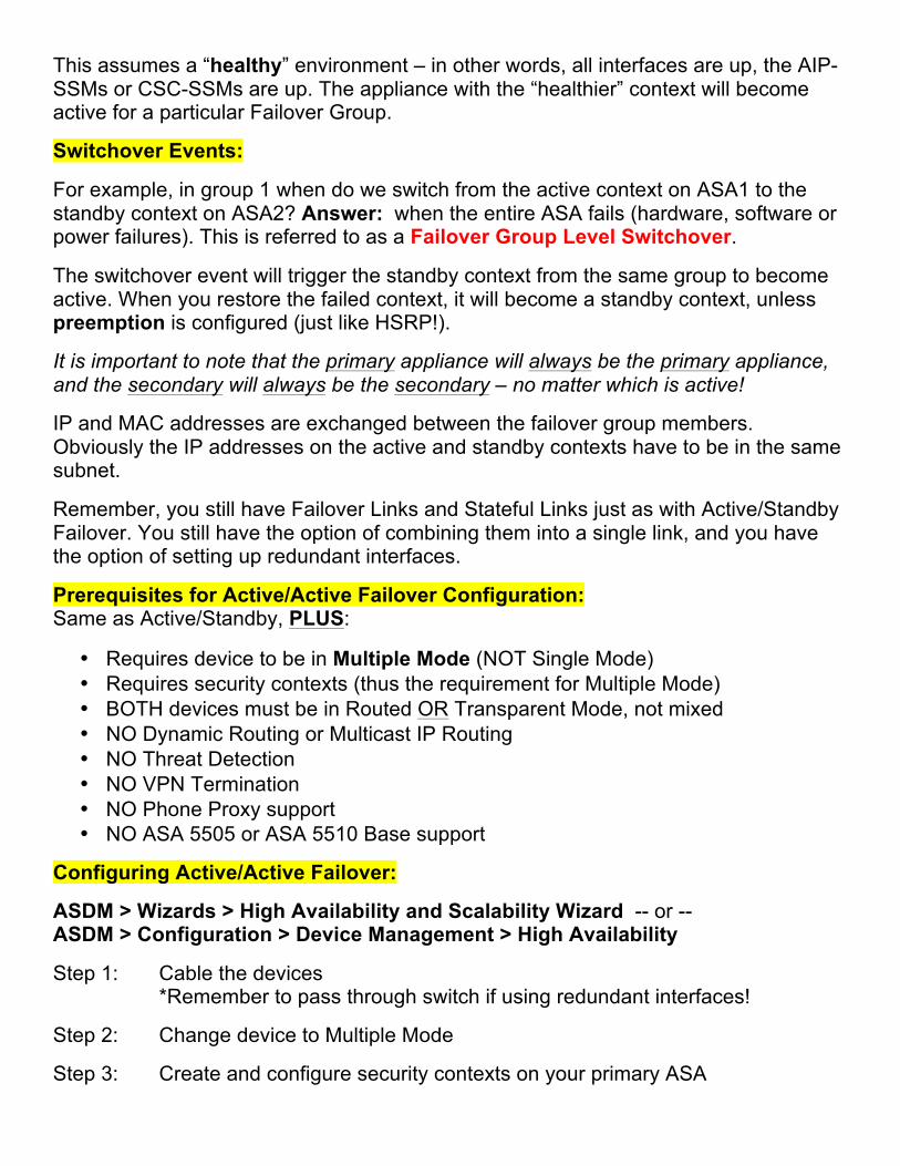
This assumes a “healthy” environment – in other words, all interfaces are up, the AIP-SSMs or CSC-SSMs are up. The appliance with the “healthier” context will become active for a particular Failover Group.
Switchover Events:
For example, in group 1 when do we switch from the active context on ASA1 to the standby context on ASA2? Answer: when the entire ASA fails (hardware, software or power failures). This is referred to as a Failover Group Level Switchover.
The switchover event will trigger the standby context from the same group to become active. When you restore the failed context, it will become a standby context, unless preemption is configured (just like HSRP!).
It is important to note that the primary appliance will always be the primary appliance, and the secondary will always be the secondary – no matter which is active!
IP and MAC addresses are exchanged between the failover group members. Obviously the IP addresses on the active and standby contexts have to be in the same subnet.
Remember, you still have Failover Links and Stateful Links just as with Active/Standby Failover. You still have the option of combining them into a single link, and you have the option of setting up redundant interfaces.
Prerequisites for Active/Active Failover Configuration: Same as Active/Standby, PLUS:
• Requires device to be in Multiple Mode (NOT Single Mode) • Requires security contexts (thus the requirement for Multiple Mode) • BOTH devices must be in Routed OR Transparent Mode, not mixed • NO Dynamic Routing or Multicast IP Routing • NO Threat Detection • NO VPN Termination • NO Phone Proxy support • NO ASA 5505 or ASA 5510 Base support
Configuring Active/Active Failover:
ASDM > Wizards > High Availability and Scalability Wizard -- or -- ASDM > Configuration > Device Management > High Availability
Step 1: Cable the devices *Remember to pass through switch if using redundant interfaces!
Step 2: Change device to Multiple Mode
Step 3: Create and configure security contexts on your primary ASA
Step 4: Create 2 Failover Groups on primary ASA
Step 5: Assign contexts to applicable groups
Step 6: Configure A/A Failover on primary ASA CLI: failover
Step 7: Configure A/A Failover on secondary ASA
Step 8: Configure standby IP addresses in each context
… the wizard will walk you through each of these steps. Refer to the Cisco ASA Configuration Guide for the particular OS version you are using!
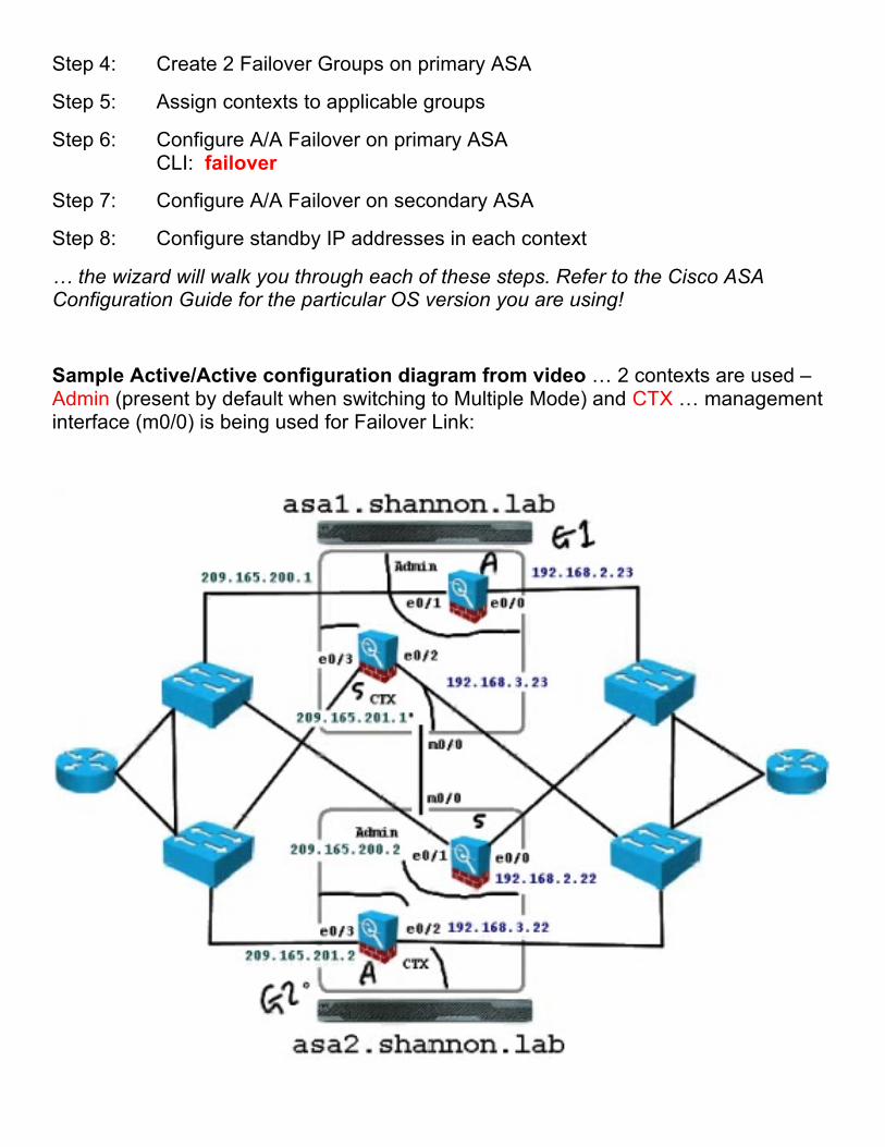
Sample Active/Active configuration diagram from video … 2 contexts are used – Admin (present by default when switching to Multiple Mode) and CTX … management interface (m0/0) is being used for Failover Link:

Configuring Active/Active Failover via CLI:
• By default, when you have Stateful Failover enabled, HTTP states will NOT be transferred. The command “replication http” enables this
• The “preempt” command is specified in each group. If the active device fails and later comes back, it can resume its previous role. Think HSRP!
• Notice the “context admin” and “context CTX” sections and the “join-failover-group x” commands which assign the contexts to the failover groups
• The “failover key xxx” assigns an optional encryption key • The “failover lan interface FAILOVER Management0/0” command specifies that
the management interface is to be used for the Failover Link (hello packets and health information exchanged via this link)
• The “failover link FAILOVER Management0/0” command specifies that the management interface is to be used for the Stateful Link (state information exchanged via this link)
• The “failover interface ip FAILOVER x.x.x.x x.x.x.x standby x.x.x.x” assigns active and standby IP addresses to the failover link
• The “failover” command is the most important – this command enables failover altogether!
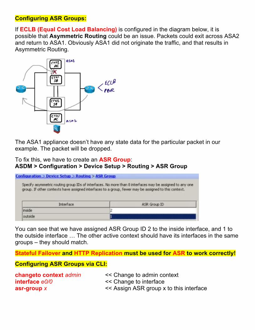
Configuring ASR Groups:
If ECLB (Equal Cost Load Balancing) is configured in the diagram below, it is possible that Asymmetric Routing could be an issue. Packets could exit across ASA2 and return to ASA1. Obviously ASA1 did not originate the traffic, and that results in Asymmetric Routing.
The ASA1 appliance doesn’t have any state data for the particular packet in our example. The packet will be dropped.
To fix this, we have to create an ASR Group: ASDM > Configuration > Device Setup > Routing > ASR Group
You can see that we have assigned ASR Group ID 2 to the inside interface, and 1 to the outside interface … The other active context should have its interfaces in the same groups – they should match.
Stateful Failover and HTTP Replication must be used for ASR to work correctly!
Configuring ASR Groups via CLI:
changeto context admin << Change to admin context interface e0/0 << Change to interface asr-group x << Assign ASR group x to this interface
Security Services Modules (SSMs):
SSM Module Types:
The exam primarily covers the SSC5 and the CSC-SSM.
o AIP à Intrusion Prevention (runs embedded Red Hat Linux) o SSC5 (used in the ASA 5505) o SSM-10 o SSM-20 o SSM-40 o Runs the same code as IOS IPS o Signature-based IDS/IPS o Anomaly-based IDS/IPS o Reputation-based IDS/IPS
o CSC à Content Security (runs embedded Trend Micro InterScan)
o SSM-10 o SSM-20 o Base license has anti-virus, anti-spyware, and file blocking o Feature upgrade license adds anti-spam, content control for email, URL
blocking / filtering and anti-phishing
SSMs extend the feature set of the ASA. They have their own dedicated CPU, RAM, flash memory and file system. They also have a dedicated out-of-band management interface. The SSC5 does NOT have this.
The hardware is the same between like models of the AIP-SSMs and CSC-SSMs – the difference is software. The 10, 20 and 40 modules differ only by CPU power and RAM. The SSM-40 supports 4GB of RAM and 2GB of flash memory, whereas the SSC5 supports 512MB of RAM and 512MB of flash memory.
Note: the software can NOT be interchanged (you can’t run CSC software on an AIP, or vice versa).
We define which traffic is sent to the SSM for further processing via policy – MPF!
Inline Mode is the best way to implement AIP-SSMs. Even though the SSM is in the same physical hardware as the firewall, the firewall processes the packet FIRST, and then it’s handed off to the SSM via an internal gigabit Ethernet connection.
Promiscuous Mode is also available for the AIP-SSMs. A COPY of the traffic is then sent to the IDS (NOT IPS, because it’s NOT inline) for processing.
Failure Management Mode à Fail-Open or Fail-Closed? Applies to AIP AND CSC SSMs. If the SSM fails, should traffic still be processed? This is a policy decision.
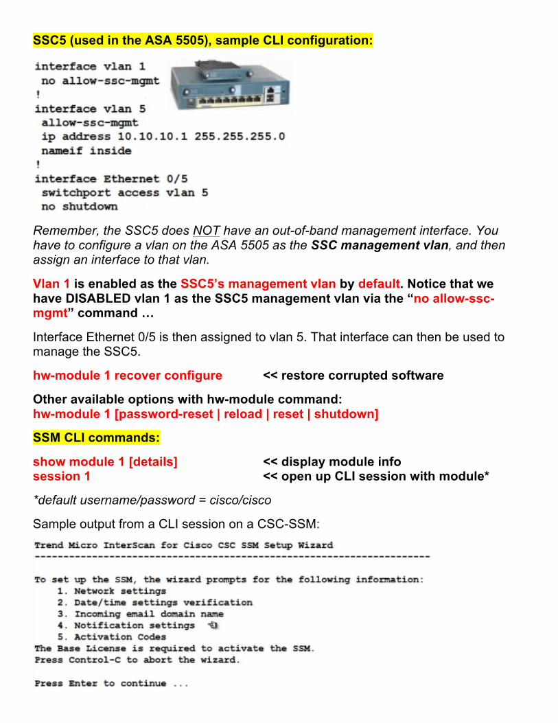
SSC5 (used in the ASA 5505), sample CLI configuration:
Remember, the SSC5 does NOT have an out-of-band management interface. You have to configure a vlan on the ASA 5505 as the SSC management vlan, and then assign an interface to that vlan.
Vlan 1 is enabled as the SSC5’s management vlan by default. Notice that we have DISABLED vlan 1 as the SSC5 management vlan via the “no allow-ssc-mgmt” command …
Interface Ethernet 0/5 is then assigned to vlan 5. That interface can then be used to manage the SSC5.
hw-module 1 recover configure << restore corrupted software
Other available options with hw-module command: hw-module 1 [password-reset | reload | reset | shutdown]
SSM CLI commands:
show module 1 [details] << display module info session 1 << open up CLI session with module*
*default username/password = cisco/cisco
Sample output from a CLI session on a CSC-SSM:
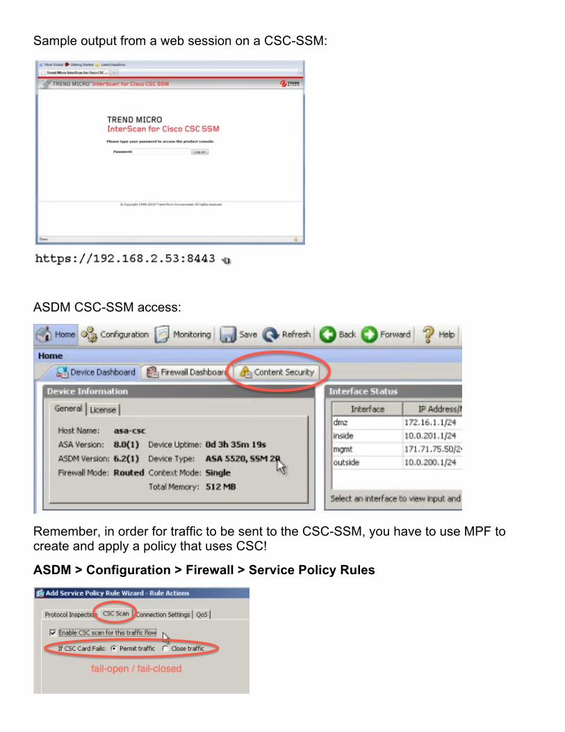
Sample output from a web session on a CSC-SSM:
ASDM CSC-SSM access:
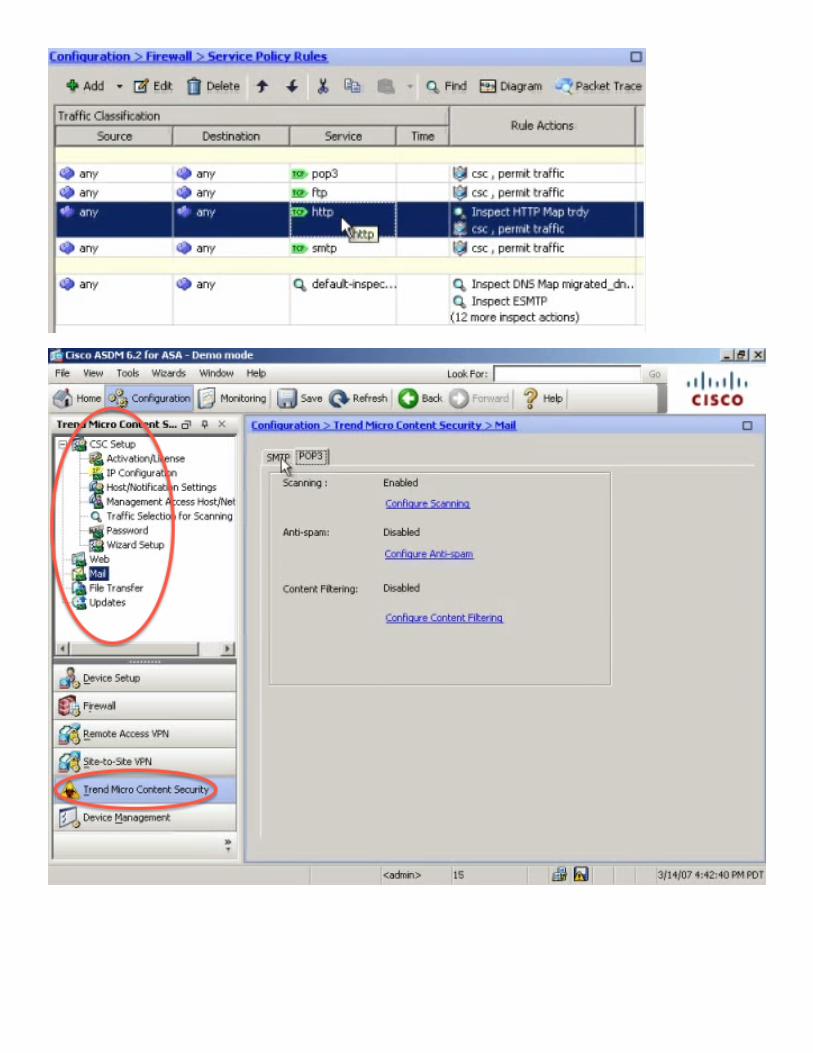
Remember, in order for traffic to be sent to the CSC-SSM, you have to use MPF to create and apply a policy that uses CSC!
ASDM > Configuration > Firewall > Service Policy Rules
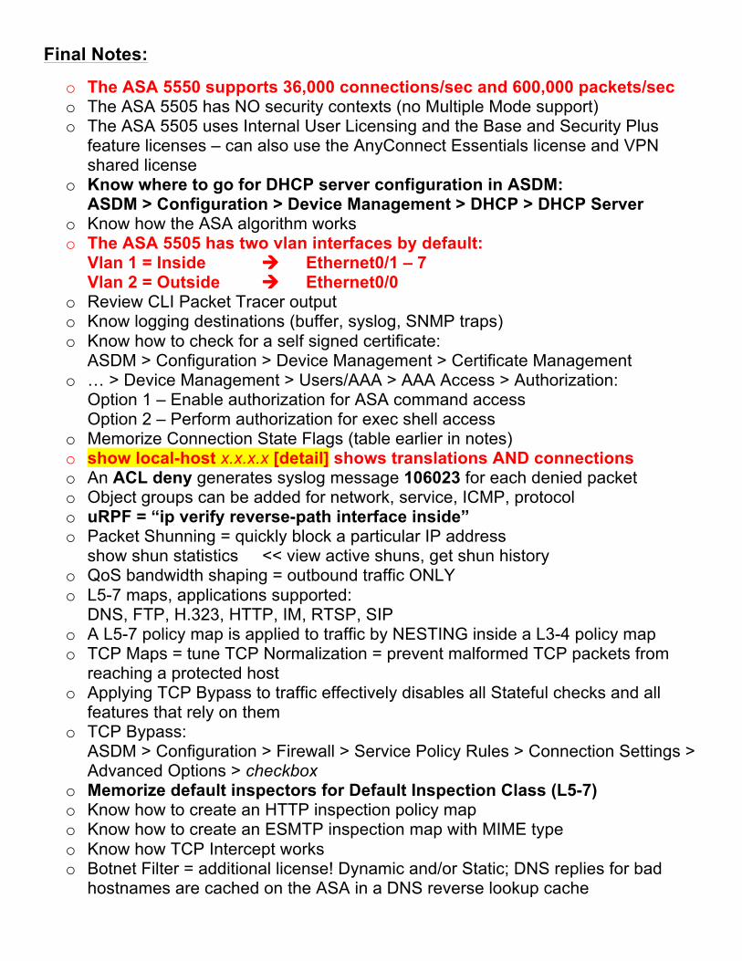
Final Notes:
o The ASA 5550 supports 36,000 connections/sec and 600,000 packets/sec o The ASA 5505 has NO security contexts (no Multiple Mode support) o The ASA 5505 uses Internal User Licensing and the Base and Security Plus
feature licenses – can also use the AnyConnect Essentials license and VPN shared license
o Know where to go for DHCP server configuration in ASDM: ASDM > Configuration > Device Management > DHCP > DHCP Server
o Know how the ASA algorithm works o The ASA 5505 has two vlan interfaces by default:
Vlan 1 = Inside à Ethernet0/1 – 7 Vlan 2 = Outside à Ethernet0/0
o Review CLI Packet Tracer output o Know logging destinations (buffer, syslog, SNMP traps) o Know how to check for a self signed certificate:
ASDM > Configuration > Device Management > Certificate Management o … > Device Management > Users/AAA > AAA Access > Authorization:
Option 1 – Enable authorization for ASA command access Option 2 – Perform authorization for exec shell access
o Memorize Connection State Flags (table earlier in notes) o show local-host x.x.x.x [detail] shows translations AND connections o An ACL deny generates syslog message 106023 for each denied packet o Object groups can be added for network, service, ICMP, protocol o uRPF = “ip verify reverse-path interface inside” o Packet Shunning = quickly block a particular IP address
show shun statistics << view active shuns, get shun history o QoS bandwidth shaping = outbound traffic ONLY o L5-7 maps, applications supported:
DNS, FTP, H.323, HTTP, IM, RTSP, SIP o A L5-7 policy map is applied to traffic by NESTING inside a L3-4 policy map o TCP Maps = tune TCP Normalization = prevent malformed TCP packets from
reaching a protected host o Applying TCP Bypass to traffic effectively disables all Stateful checks and all
features that rely on them o TCP Bypass:
ASDM > Configuration > Firewall > Service Policy Rules > Connection Settings > Advanced Options > checkbox
o Memorize default inspectors for Default Inspection Class (L5-7) o Know how to create an HTTP inspection policy map o Know how to create an ESMTP inspection map with MIME type o Know how TCP Intercept works o Botnet Filter = additional license! Dynamic and/or Static; DNS replies for bad
hostnames are cached on the ASA in a DNS reverse lookup cache
o Enable DNS Snooping: ASDM > Configuration > Firewall > Botnet Traffic Filter
o Basic Threat Detection generates syslog message 733100 o Advanced Threat Detection statistics for hosts = biggest performance
impact to ASA! o CLI to enable Basic Threat Detection:
“threat-detection basic-threat” o Scanning Threat Detection generates syslog message 733101 o Traffic Shaping vs. Traffic Policing à know the difference!
Traffic Shaping = buffers traffic, outbound ONLY o Priority Queueing sets size in packets (queue-limit) as well as transmission ring
size (tx-ring-limit) o Review DNS Rewrite feature o Know NAT Control bypass methods à NAT Exemption is most recommended o Instead of configuring static NAT and interface access rules separately, you can
use the Public Server feature in ASDM o Review Transparent Mode unsupported features! o Review EtherType ACL à can’t be < 0x600, NO CDP, YES BPDU, ARP
permitted by default in Transparent Mode o If Dynamic MAC Address Learning is DISABLED, MAC addresses must be
manually configured à could result in empty MAC address table! o Review Multiple Mode unsupported features! o When you use shared interfaces (or sub-ifs) assign DIFFERENT MAC addresses
to the shared interface in each context o If asterisk in “show context” output, indicates CURRENT ADMIN CONTEXT o Know redundant interfaces o Know data NOT passed to standby with Stateful Failover o Health is monitored over failover link using special hello packets o Review output of “show failover” o Know the order for Zero-Downtime Failover Pair Upgrade:
1. Download software on both devices and specify to load new image 2. Reload standby unit 3. Force active unit to failover to standby 4. Reload previously active unit 5. Return original active unit to active state
o To show information about interfaces monitored for failover, use “show monitor-interface” command
o To use ASA to route traffic in load-sharing scenario, use ECLB / PBR
-- End --