Embed Size (px)
Citation preview
CC-Link System RS-232 Interface ModuleUser's Manual (MELSOFT Connection Mode)

SAFETY PRECAUTIONS(Always read these instructions before using this equipment.)
Before using this product, please read this manual and the relevant manuals introduced in this manual
carefully and pay full attention to safety to handle the product correctly.
The instructions given in this manual are concerned with this product only. For the safety instructions of the
programmable controller system, please read the user's manual for the CPU module used.
In this manual, the safety precautions are classified into two levels: "WARNING" and "CAUTION".
Note that the CAUTION level may lead to a serious consequence according to the circumstances.
Always follow the instructions of both levels because they are important to personal safety.
Please save this manual to make it accessible when required and always forward it to the end user.
[Design Precautions]
WARNING● When controlling a running programmable controller (data modification) by connecting a peripheral
to a CPU module or connecting a personal computer to an intelligent/special function module, create
an interlock circuit on the sequence program so that the whole system will operate safely all the time.
Also, before performing other controls (e.g. program modification, operating status change (status
control)), read this manual carefully and ensure the safety.
Especially, in the control from an external device to a programmable controller in a remote location,
some programmable-controller-side problems cannot be resolved immediately due to a data
communication failure.
To prevent this, establish corrective procedures for communication failure between the external
device and the programmable controller CPU, as well as creating an interlock circuit on the
sequence program.
● In the case of a data link error, the operation status of a faulty station is as shown below. Using the
communication status information, create an interlock circuit on the sequence program for the
system to operate safely.
Incorrect output or malfunction can lead to an accident.
(1) All of general-purpose inputs from this module turn OFF.
(2) All of general-purpose outputs from this module turn OFF.
● Depending on the module failure, inputs and outputs may turn ON or OFF incorrectly.
For I/O signals that may cause a serious accident, provide an external monitoring circuit.
WARNING
CAUTION
Indicates that incorrect handling may cause hazardous conditions,
resulting in death or severe injury.
Indicates that incorrect handling may cause hazardous conditions,
resulting in minor or moderate injury or property damage.
A - 1
[Installation Precautions]
CAUTION● Do not bunch the control wires or communication cables with the main circuit or power wires, or
install them close to each other.
They should be installed 100 mm (3.94 inch) or more from each other.
Not doing so could result in noise that would cause erroneous operation.
● Always use the data link terminal block for connection of a CC-Link dedicated cable to a master
module.
Care must be taken because, if the cable is incorrectly inserted into the general-purpose I/O terminal
block instead of the data link terminal block, the module will break down.
CAUTION● Use the programmable controller in an environment that meets the general specifications given in
this manual.
Using this programmable controller in an environment outside the range of the general specifications
could result in electric shock, fire, erroneous operation, and damage to or deterioration of the
product.
● Using a tool specified by the manufacturer, correctly press, crimp, or solder the wires of the
connector and securely connect the connector to the module.
Incomplete connection may cause a short circuit and/or malfunctions.
● Do not directly touch the module's conductive parts or electronic components.
Touching the conductive parts could cause an operation failure or give damage to the module.
● Securely fix the module with the DIN rail or installation screws. Installation screws must be tightened
within the specified torque range.
A loose screw may cause a drop of the module, short circuit or malfunction.
Overtightening may damage the screw, resulting in a drop of the module or a short circuit.
● Completely connect each cable connector to each receptacle.
Incomplete connection may cause a malfunction due to poor contact.
A - 2
[Wiring Precautions]
CAUTION● Be sure to shut off all phases of the external power supply used by the system before installation or
wiring.
Failure to do so may cause an electric shock, damage to the product and/or malfunctions.
● Attach the terminal cover to the product before energizing and operating the system after installation
or wiring.
Failure to do so may cause an electric shock.
● Be sure to ground the FG terminals and LG terminals to the protective ground conductor.
Failure to do so may result in malfunctions.
A - 3
[Wiring Precautions]
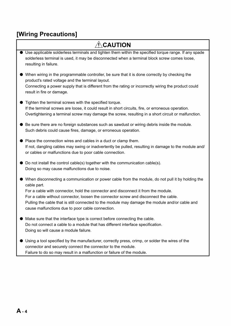
CAUTION● Use applicable solderless terminals and tighten them within the specified torque range. If any spade
solderless terminal is used, it may be disconnected when a terminal block screw comes loose,
resulting in failure.
● When wiring in the programmable controller, be sure that it is done correctly by checking the
product's rated voltage and the terminal layout.
Connecting a power supply that is different from the rating or incorrectly wiring the product could
result in fire or damage.
● Tighten the terminal screws with the specified torque.
If the terminal screws are loose, it could result in short circuits, fire, or erroneous operation.
Overtightening a terminal screw may damage the screw, resulting in a short circuit or malfunction.
● Be sure there are no foreign substances such as sawdust or wiring debris inside the module.
Such debris could cause fires, damage, or erroneous operation.
● Place the connection wires and cables in a duct or clamp them.
If not, dangling cables may swing or inadvertently be pulled, resulting in damage to the module and/
or cables or malfunctions due to poor cable connection.
● Do not install the control cable(s) together with the communication cable(s).
Doing so may cause malfunctions due to noise.
● When disconnecting a communication or power cable from the module, do not pull it by holding the
cable part.
For a cable with connector, hold the connector and disconnect it from the module.
For a cable without connector, loosen the connector screw and disconnect the cable.
Pulling the cable that is still connected to the module may damage the module and/or cable and
cause malfunctions due to poor cable connection.
● Make sure that the interface type is correct before connecting the cable.
Do not connect a cable to a module that has different interface specification.
Doing so will cause a module failure.
● Using a tool specified by the manufacturer, correctly press, crimp, or solder the wires of the
connector and securely connect the connector to the module.
Failure to do so may result in a malfunction or failure of the module.
A - 4
[Startup·Maintenance Precautions]
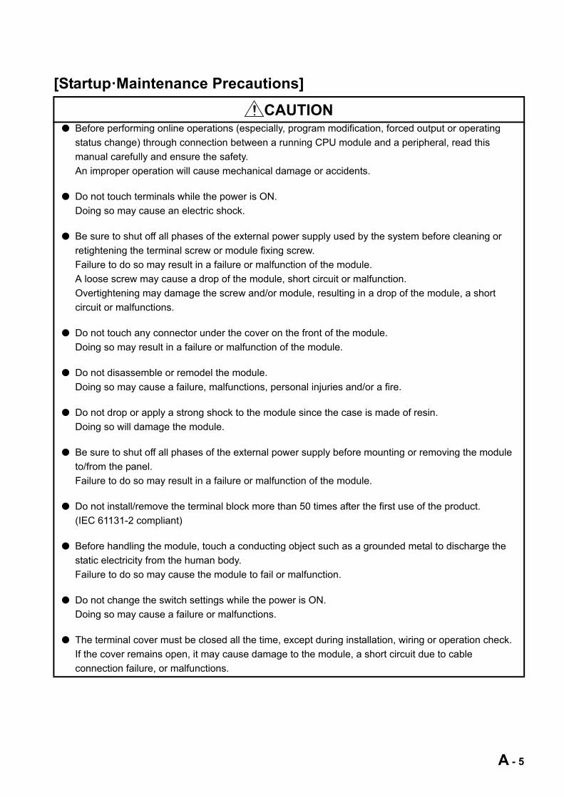
CAUTION● Before performing online operations (especially, program modification, forced output or operating
status change) through connection between a running CPU module and a peripheral, read this
manual carefully and ensure the safety.
An improper operation will cause mechanical damage or accidents.
● Do not touch terminals while the power is ON.
Doing so may cause an electric shock.
● Be sure to shut off all phases of the external power supply used by the system before cleaning or
retightening the terminal screw or module fixing screw.
Failure to do so may result in a failure or malfunction of the module.
A loose screw may cause a drop of the module, short circuit or malfunction.
Overtightening may damage the screw and/or module, resulting in a drop of the module, a short
circuit or malfunctions.
● Do not touch any connector under the cover on the front of the module.
Doing so may result in a failure or malfunction of the module.
● Do not disassemble or remodel the module.
Doing so may cause a failure, malfunctions, personal injuries and/or a fire.
● Do not drop or apply a strong shock to the module since the case is made of resin.
Doing so will damage the module.
● Be sure to shut off all phases of the external power supply before mounting or removing the module
to/from the panel.
Failure to do so may result in a failure or malfunction of the module.
● Do not install/remove the terminal block more than 50 times after the first use of the product.
(IEC 61131-2 compliant)
● Before handling the module, touch a conducting object such as a grounded metal to discharge the
static electricity from the human body.
Failure to do so may cause the module to fail or malfunction.
● Do not change the switch settings while the power is ON.
Doing so may cause a failure or malfunctions.
● The terminal cover must be closed all the time, except during installation, wiring or operation check.
If the cover remains open, it may cause damage to the module, a short circuit due to cable
connection failure, or malfunctions.
A - 5

[Disposal Precautions]
CAUTION● When disposing of this product, treat it as industrial waste.
A - 6
CONDITIONS OF USE FOR THE PRODUCT
(1) Mitsubishi programmable controller ("the PRODUCT") shall be used in conditions;
i) where any problem, fault or failure occurring in the PRODUCT, if any, shall not lead to any major
or serious accident; and
ii) where the backup and fail-safe function are systematically or automatically provided outside of
the PRODUCT for the case of any problem, fault or failure occurring in the PRODUCT.
(2) The PRODUCT has been designed and manufactured for the purpose of being used in general
industries.
MITSUBISHI SHALL HAVE NO RESPONSIBILITY OR LIABILITY (INCLUDING, BUT NOT
LIMITED TO ANY AND ALL RESPONSIBILITY OR LIABILITY BASED ON CONTRACT,
WARRANTY, TORT, PRODUCT LIABILITY) FOR ANY INJURY OR DEATH TO PERSONS OR
LOSS OR DAMAGE TO PROPERTY CAUSED BY the PRODUCT THAT ARE OPERATED OR
USED IN APPLICATION NOT INTENDED OR EXCLUDED BY INSTRUCTIONS, PRECAUTIONS,
OR WARNING CONTAINED IN MITSUBISHI'S USER, INSTRUCTION AND/OR SAFETY
MANUALS, TECHNICAL BULLETINS AND GUIDELINES FOR the PRODUCT.
("Prohibited Application")
Prohibited Applications include, but not limited to, the use of the PRODUCT in;
• Nuclear Power Plants and any other power plants operated by Power companies, and/or any
other cases in which the public could be affected if any problem or fault occurs in the PRODUCT.
• Railway companies or Public service purposes, and/or any other cases in which establishment of
a special quality assurance system is required by the Purchaser or End User.
• Aircraft or Aerospace, Medical applications, Train equipment, transport equipment such as
Elevator and Escalator, Incineration and Fuel devices, Vehicles, Manned transportation,
Equipment for Recreation and Amusement, and Safety devices, handling of Nuclear or
Hazardous Materials or Chemicals, Mining and Drilling, and/or other applications where there is a
significant risk of injury to the public or property.
Notwithstanding the above, restrictions Mitsubishi may in its sole discretion, authorize use of the
PRODUCT in one or more of the Prohibited Applications, provided that the usage of the PRODUCT
is limited only for the specific applications agreed to by Mitsubishi and provided further that no
special quality assurance or fail-safe, redundant or other safety features which exceed the general
specifications of the PRODUCTs are required. For details, please contact the Mitsubishi
representative in your region.
A - 7
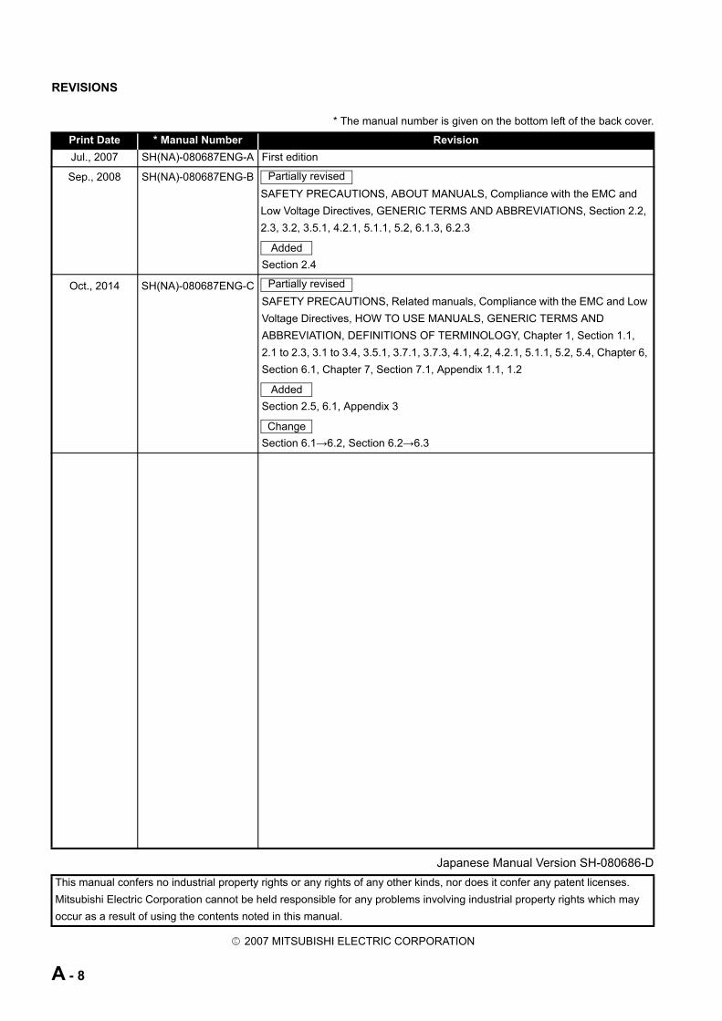
REVISIONS
* The manual number is given on the bottom left of the back cover.
Japanese Manual Version SH-080686-D
2007 MITSUBISHI ELECTRIC CORPORATION
Print Date * Manual Number Revision
Jul., 2007 SH(NA)-080687ENG-A First edition
Sep., 2008 SH(NA)-080687ENG-B
SAFETY PRECAUTIONS, ABOUT MANUALS, Compliance with the EMC and
Low Voltage Directives, GENERIC TERMS AND ABBREVIATIONS, Section 2.2,
2.3, 3.2, 3.5.1, 4.2.1, 5.1.1, 5.2, 6.1.3, 6.2.3
Section 2.4
Oct., 2014 SH(NA)-080687ENG-C
SAFETY PRECAUTIONS, Related manuals, Compliance with the EMC and Low
Voltage Directives, HOW TO USE MANUALS, GENERIC TERMS AND
ABBREVIATION, DEFINITIONS OF TERMINOLOGY, Chapter 1, Section 1.1,
2.1 to 2.3, 3.1 to 3.4, 3.5.1, 3.7.1, 3.7.3, 4.1, 4.2, 4.2.1, 5.1.1, 5.2, 5.4, Chapter 6,
Section 6.1, Chapter 7, Section 7.1, Appendix 1.1, 1.2
Section 2.5, 6.1, Appendix 3
Section 6.1→6.2, Section 6.2→6.3
This manual confers no industrial property rights or any rights of any other kinds, nor does it confer any patent licenses.
Mitsubishi Electric Corporation cannot be held responsible for any problems involving industrial property rights which may
occur as a result of using the contents noted in this manual.
Partially revised
Added
Partially revised
Added
Change
A - 8
INTRODUCTION
Thank you for purchasing the Mitsubishi MELSEC-A series programmable controller.
Before using the product, please read this manual carefully to familiarize yourself with the features and
performance of the A series programmable controller to ensure proper use of the product.
CONTENTSSAFETY PRECAUTIONS .................................................................................................................................A - 1
CONDITIONS OF USE FOR THE PRODUCT..................................................................................................A - 7
REVISIONS.......................................................................................................................................................A - 8
ABOUT MANUALS .........................................................................................................................................A - 11
COMPLIANCE With THE EMC AND LOW VOLTAGE DIRECTIVES.............................................................A - 12
HOW TO USE MANUALS...............................................................................................................................A - 13
GENERIC TERMS AND ABBREVIATIONS....................................................................................................A - 16
DEFINITIONS OF TERMINOLOGY................................................................................................................A - 18
PACKING LIST ...............................................................................................................................................A - 19
CHAPTER 1 OVERVIEW 1 - 1 to 1 - 5
1.1 Features........................................................................................................................................... 1 - 2
CHAPTER 2 SYSTEM CONFIGURATION 2 - 1 to 2 - 8
2.1 System Configuration ...................................................................................................................... 2 - 1
2.2 Applicable System ........................................................................................................................... 2 - 2
2.3 Precautions for System Configuration ............................................................................................. 2 - 3
2.4 Checking the Hardware Version ...................................................................................................... 2 - 8
2.5 Checking the Production Number (SERIAL).................................................................................... 2 - 8
CHAPTER 3 SPECIFICATIONS 3 - 1 to 3 - 13
3.1 General Specifications..................................................................................................................... 3 - 1
3.2 Performance Specifications ............................................................................................................. 3 - 2
3.3 Function List .................................................................................................................................... 3 - 3
3.4 CC-Link Dedicated Cable Specifications ......................................................................................... 3 - 4
3.5 RS-232 Interface Specifications ...................................................................................................... 3 - 5
3.5.1 RS-232 connector specifications .............................................................................................. 3 - 5
3.5.2 RS-232 cable specifications ..................................................................................................... 3 - 5
3.6 General-purpose I/O Specifications................................................................................................. 3 - 6
3.7 Remote I/O and Remote Register ................................................................................................... 3 - 7
3.7.1 Remote I/O list .......................................................................................................................... 3 - 7
3.7.2 Remote I/O details.................................................................................................................... 3 - 9
3.7.3 Remote register list................................................................................................................. 3 - 10
3.8 Buffer Memory ............................................................................................................................... 3 - 12
3.8.1 Buffer memory list................................................................................................................... 3 - 12
A - 9
CHAPTER 4 FUNCTIONS 4 - 1 to 4 - 5
4.1 Selecting Mode and Function(s) ...................................................................................................... 4 - 1
4.2 MELSOFT Connection Function...................................................................................................... 4 - 2
4.2.1 Accessible range ...................................................................................................................... 4 - 4
CHAPTER 5 PREPARATORY PROCEDURES AND SETTING 5 - 1 to 5 - 14
5.1 Implementation and Installation ....................................................................................................... 5 - 1
5.1.1 Handling precautions................................................................................................................ 5 - 1
5.2 Preparatory Procedures and Setting ............................................................................................... 5 - 3
5.3 Installation Environment .................................................................................................................. 5 - 4
5.4 Part Names and Settings................................................................................................................. 5 - 4
5.5 AJ65BT-R2N Single Unit Test ....................................................................................................... 5 - 10
5.5.1 Hardware test ......................................................................................................................... 5 - 10
5.6 Wiring............................................................................................................................................. 5 - 12
5.6.1 CC-Link dedicated cable connection method ......................................................................... 5 - 12
5.6.2 External device connection method........................................................................................ 5 - 13
CHAPTER 6 MELSOFT CONNECTION MODE SETTING 6 - 1 to 6 - 21
6.1 Setting When LCPU is Used............................................................................................................ 6 - 2
6.1.1 Switch settings of each station ................................................................................................. 6 - 3
6.1.2 Parameter setting ..................................................................................................................... 6 - 4
6.1.3 Connection target setting.......................................................................................................... 6 - 6
6.2 Setting When QCPU (Q mode)/QnACPU is Used........................................................................... 6 - 7
6.2.1 Switch settings of each station ................................................................................................. 6 - 8
6.2.2 Parameter setting ................................................................................................................... 6 - 10
6.2.3 Connection target setting ....................................................................................................... 6 - 13
6.3 Setting When ACPU/QCPU (A mode) is Used .............................................................................. 6 - 15
6.3.1 Switch settings of each station ............................................................................................... 6 - 16
6.3.2 Parameter setting ................................................................................................................... 6 - 18
6.3.3 Connection target setting ....................................................................................................... 6 - 21
CHAPTER 7 TROUBLESHOOTING 7 - 1 to 7 - 7
7.1 Troubleshooting When Using the MELSOFT Connection Function ................................................ 7 - 2
7.2 Error Code List................................................................................................................................. 7 - 7
APPENDICES App - 1 to App - 5
Appendix 1 Differences between AJ65BT-R2N and AJ65BT-G4-S3 ..................................................App - 1
Appendix 1.1 Specifications comparisons......................................................................................App - 1
Appendix 1.2 Procedures and precautions for replacing AJ65BT-G4-S3 with AJ65BT-R2N.........App - 3
Appendix 2 External Dimensions.........................................................................................................App - 4
Appendix 3 RS-232 Interfaces Used for the AJ65BT-R2N..................................................................App - 4
INDEX Index - 1 to Index - 1
A - 10
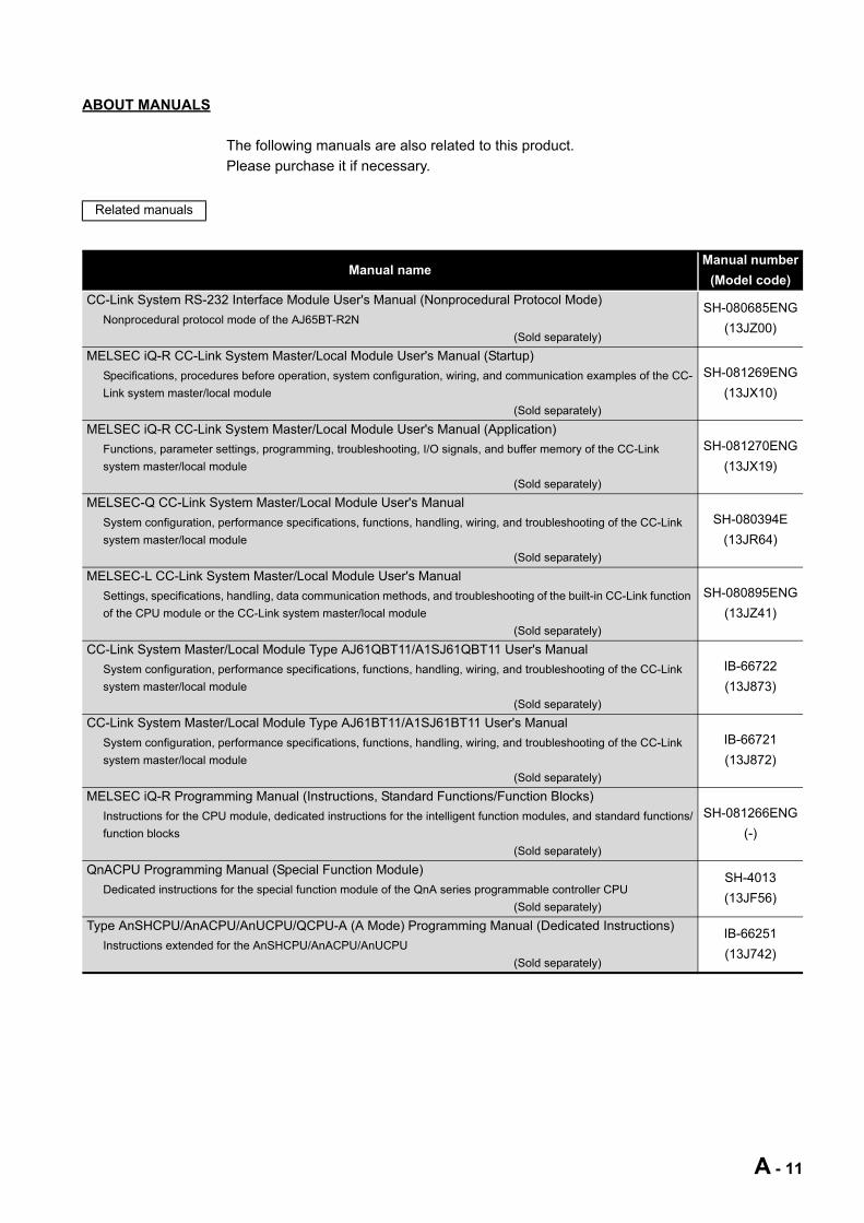
ABOUT MANUALS
The following manuals are also related to this product.
Please purchase it if necessary.
Related manuals
Manual nameManual number
(Model code)
CC-Link System RS-232 Interface Module User's Manual (Nonprocedural Protocol Mode)
Nonprocedural protocol mode of the AJ65BT-R2N
(Sold separately)
SH-080685ENG
(13JZ00)
MELSEC iQ-R CC-Link System Master/Local Module User's Manual (Startup)
Specifications, procedures before operation, system configuration, wiring, and communication examples of the CC-
Link system master/local module
(Sold separately)
SH-081269ENG
(13JX10)
MELSEC iQ-R CC-Link System Master/Local Module User's Manual (Application)
Functions, parameter settings, programming, troubleshooting, I/O signals, and buffer memory of the CC-Link
system master/local module
(Sold separately)
SH-081270ENG
(13JX19)
MELSEC-Q CC-Link System Master/Local Module User's Manual
System configuration, performance specifications, functions, handling, wiring, and troubleshooting of the CC-Link
system master/local module
(Sold separately)
SH-080394E
(13JR64)
MELSEC-L CC-Link System Master/Local Module User's Manual
Settings, specifications, handling, data communication methods, and troubleshooting of the built-in CC-Link function
of the CPU module or the CC-Link system master/local module
(Sold separately)
SH-080895ENG
(13JZ41)
CC-Link System Master/Local Module Type AJ61QBT11/A1SJ61QBT11 User's Manual
System configuration, performance specifications, functions, handling, wiring, and troubleshooting of the CC-Link
system master/local module
(Sold separately)
IB-66722
(13J873)
CC-Link System Master/Local Module Type AJ61BT11/A1SJ61BT11 User's Manual
System configuration, performance specifications, functions, handling, wiring, and troubleshooting of the CC-Link
system master/local module
(Sold separately)
IB-66721
(13J872)
MELSEC iQ-R Programming Manual (Instructions, Standard Functions/Function Blocks)
Instructions for the CPU module, dedicated instructions for the intelligent function modules, and standard functions/
function blocks
(Sold separately)
SH-081266ENG
(-)
QnACPU Programming Manual (Special Function Module)
Dedicated instructions for the special function module of the QnA series programmable controller CPU
(Sold separately)
SH-4013
(13JF56)
Type AnSHCPU/AnACPU/AnUCPU/QCPU-A (A Mode) Programming Manual (Dedicated Instructions)
Instructions extended for the AnSHCPU/AnACPU/AnUCPU
(Sold separately)
IB-66251
(13J742)
A - 11
COMPLIANCE WITH THE EMC AND LOW VOLTAGE DIRECTIVES
(1) For programmable controller systemTo ensure that Mitsubishi programmable controllers maintain EMC and Low Voltage
Directives when incorporated into other machinery or equipment, certain measures
may be necessary. Please refer to one of the following manuals.
• User's manual for the CPU module or head module used
• Safety Guidelines
(This manual is included with the CPU module, base unit, or head module.)
The CE mark on the side of the programmable controller indicates compliance with
EMC and Low Voltage Directives.
(2) For the productTo ensure that this product maintains EMC and Low Voltage Directives, please refer
to one of the manuals listed under (1).
A - 12
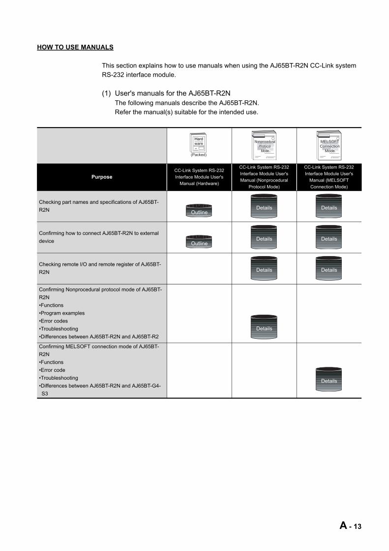
HOW TO USE MANUALS
This section explains how to use manuals when using the AJ65BT-R2N CC-Link system
RS-232 interface module.
(1) User's manuals for the AJ65BT-R2NThe following manuals describe the AJ65BT-R2N.
Refer the manual(s) suitable for the intended use.
PurposeCC-Link System RS-232
Interface Module User's
Manual (Hardware)
CC-Link System RS-232
Interface Module User's
Manual (Nonprocedural
Protocol Mode)
CC-Link System RS-232
Interface Module User's
Manual (MELSOFT
Connection Mode)
Checking part names and specifications of AJ65BT-
R2N
Confirming how to connect AJ65BT-R2N to external
device
Checking remote I/O and remote register of AJ65BT-
R2N
Confirming Nonprocedural protocol mode of AJ65BT-
R2N
•Functions
•Program examples
•Error codes
•Troubleshooting
•Differences between AJ65BT-R2N and AJ65BT-R2
Confirming MELSOFT connection mode of AJ65BT-
R2N
•Functions
•Error code
•Troubleshooting
•Differences between AJ65BT-R2N and AJ65BT-G4-
S3
Hardware
(Packed)
NonproceduralNonproceduralProtocolProtocol
ModeMode
NonproceduralProtocol
Mode
MELSOFTMELSOFTConnectionConnection
ModeMode
MELSOFTConnection
Mode
OutlineDetails Details
OutlineDetails Details
Details Details
Details
Details
A - 13
(2) About this manualUse this manual when you want to know the following:
(a) Features of the AJ65BT-R2N
Section 1.1 Features
(b) System configurations and applicable systems
Section 2.1 System Configuration
Section 2.2 Applicable System
(c) Performance specifications of the AJ65BT-R2N
Section 3.2 Performance Specifications
(d) Functions of the AJ65BT-R2N
CHAPTER 4 FUNCTIONS
(e) Preparatory procedures and setting of the AJ65BT-R2N
Section 5.2 Preparatory Procedures and Setting
(f) How to configure the MELSOFT connection mode settings
Section 6.1 Setting When LCPU is Used
Section 6.2 Setting When QCPU (Q mode)/QnACPU is Used
Section 6.3 Setting When ACPU/QCPU (A mode) is Used
(g) How to solve the error that has occurred
Section 7.1 Troubleshooting When Using the MELSOFT Connection
Function
Section 7.2 Error Code List
(h) Differences between the AJ65BT-R2N and AJ65BT-G4-S3
Appendix 1 Differences between AJ65BT-R2N and AJ65BT-G4-S3
A - 14
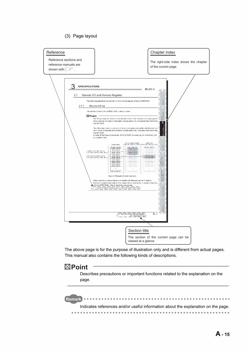
(3) Page layout
The above page is for the purpose of illustration only and is different from actual pages.
This manual also contains the following kinds of descriptions.
Describes precautions or important functions related to the explanation on the
page.
Remark
Indicates references and/or useful information about the explanation on the page.
Reference sections and
reference manuals are
shown with .
Chapter index
The right-side index shows the chapter
of the current page.
Section title
The section of the current page can be viewed at a glance.
Reference
A - 15
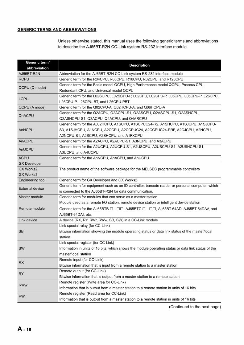
GENERIC TERMS AND ABBREVIATIONS
Unless otherwise stated, this manual uses the following generic terms and abbreviations
to describe the AJ65BT-R2N CC-Link system RS-232 interface module.
(Continued to the next page)
Generic term/
abbreviationDescription
AJ65BT-R2N Abbreviation for the AJ65BT-R2N CC-Link system RS-232 interface module
RCPU Generic term for the R04CPU, R08CPU, R16CPU, R32CPU, and R120CPU
QCPU (Q mode)Generic term for the Basic model QCPU, High Performance model QCPU, Process CPU,
Redundant CPU, and Universal model QCPU
LCPUGeneric term for the L02SCPU, L02SCPU-P, L02CPU, L02CPU-P, L06CPU, L06CPU-P, L26CPU,
L26CPU-P, L26CPU-BT, and L26CPU-PBT
QCPU (A mode) Generic term for the Q02CPU-A, Q02HCPU-A, and Q06HCPU-A
QnACPUGeneric term for the Q2ACPU, Q2ACPU-S1, Q2ASCPU, Q2ASCPU-S1, Q2ASHCPU,
Q2ASHCPU-S1, Q3ACPU, Q4ACPU, and Q4ARCPU
AnNCPU
Generic term for the A0J2HCPU, A1SCPU, A1SCPUC24-R2, A1SHCPU, A1SJCPU, A1SJCPU-
S3, A1SJHCPU, A1NCPU, A2CCPU, A2CCPUC24, A2CCPUC24-PRF, A2CJCPU, A2NCPU,
A2NCPU-S1, A2SCPU, A2SHCPU, and A1FXCPU
AnACPU Generic term for the A2ACPU, A2ACPU-S1, A3NCPU, and A3ACPU
AnUCPUGeneric term for the A2UCPU, A2UCPU-S1, A2USCPU, A2USCPU-S1, A2USHCPU-S1,
A3UCPU, and A4UCPU
ACPU Generic term for the AnNCPU, AnACPU, and AnUCPU
GX Developer
The product name of the software package for the MELSEC programmable controllersGX Works2
GX Works3
Engineering tool Generic term for GX Developer and GX Works2
External deviceGeneric term for equipment such as an ID controller, barcode reader or personal computer, which
is connected to the AJ65BT-R2N for data communication.
Master module Generic term for modules that can serve as a master station
Remote module
Module used as a remote I/O station, remote device station or intelligent device station
Generic term for the AJ65BTB - , AJ65BTC - , AJ65BT-64AD, AJ65BT-64DAV, and
AJ65BT-64DAI, etc.
Link device A device (RX, RY, RWr, RWw, SB, SW) in a CC-Link module
SB
Link special relay (for CC-Link)
Bitwise information showing the module operating status or data link status of the master/local
station
SW
Link special register (for CC-Link)
Information in units of 16 bits, which shows the module operating status or data link status of the
master/local station
RXRemote input (for CC-Link)
Bitwise information that is input from a remote station to a master station
RYRemote output (for CC-Link)
Bitwise information that is output from a master station to a remote station
RWwRemote register (Write area for CC-Link)
Information that is output from a master station to a remote station in units of 16 bits
RWrRemote register (Read area for CC-Link)
Information that is output from a master station to a remote station in units of 16 bits
A - 16

(From previous page)
Generic term/
abbreviationDescription
Remote net ver.1 modeMode selected when not increasing the cyclic transmission data size, or when replacing the
QJ61BT11 with the QJ61BT11N
Remote net ver.2 mode Mode selected when constructing a new system with the cyclic transmission data size increased
Remote net additional
mode
Mode selected when adding a Ver.2 station to a remote net ver.1 mode system and increasing the
cyclic transmission data size
A - 17
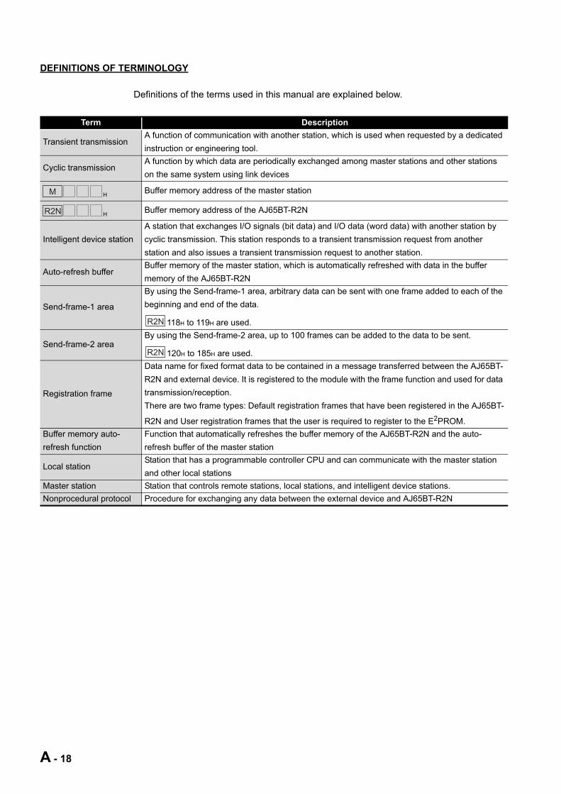
DEFINITIONS OF TERMINOLOGY
Definitions of the terms used in this manual are explained below.
Term Description
Transient transmissionA function of communication with another station, which is used when requested by a dedicated
instruction or engineering tool.
Cyclic transmissionA function by which data are periodically exchanged among master stations and other stations
on the same system using link devices
HBuffer memory address of the master station
HBuffer memory address of the AJ65BT-R2N
Intelligent device station
A station that exchanges I/O signals (bit data) and I/O data (word data) with another station by
cyclic transmission. This station responds to a transient transmission request from another
station and also issues a transient transmission request to another station.
Auto-refresh bufferBuffer memory of the master station, which is automatically refreshed with data in the buffer
memory of the AJ65BT-R2N
Send-frame-1 area
By using the Send-frame-1 area, arbitrary data can be sent with one frame added to each of the
beginning and end of the data.
118H to 119H are used.
Send-frame-2 areaBy using the Send-frame-2 area, up to 100 frames can be added to the data to be sent.
120H to 185H are used.
Registration frame
Data name for fixed format data to be contained in a message transferred between the AJ65BT-
R2N and external device. It is registered to the module with the frame function and used for data
transmission/reception.
There are two frame types: Default registration frames that have been registered in the AJ65BT-
R2N and User registration frames that the user is required to register to the E2PROM.
Buffer memory auto-
refresh function
Function that automatically refreshes the buffer memory of the AJ65BT-R2N and the auto-
refresh buffer of the master station
Local stationStation that has a programmable controller CPU and can communicate with the master station
and other local stations
Master station Station that controls remote stations, local stations, and intelligent device stations.
Nonprocedural protocol Procedure for exchanging any data between the external device and AJ65BT-R2N
M
R2N
R2N
R2N
A - 18

PACKING LIST
The following is included in the package of the AJ65BT-R2N CC-Link system RS-232
interface module.
Model Product name Quantity
AJ65BT-R2N The AJ65BT-R2N CC-Link system RS-232 interface module 1
A - 19
1 OVERVIEW
CHAPTER 1 OVERVIEW
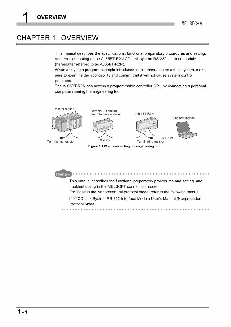
This manual describes the specifications, functions, preparatory procedures and setting,
and troubleshooting of the AJ65BT-R2N CC-Link system RS-232 interface module
(hereinafter referred to as AJ65BT-R2N).
When applying a program example introduced in this manual to an actual system, make
sure to examine the applicability and confirm that it will not cause system control
problems.
The AJ65BT-R2N can access a programmable controller CPU by connecting a personal
computer running the engineering tool.
Remark
This manual describes the functions, preparatory procedures and setting, and
troubleshooting in the MELSOFT connection mode.
For those in the Nonprocedural protocol mode, refer to the following manual.
CC-Link System RS-232 Interface Module User's Manual (Nonprocedural
Protocol Mode)
Figure 1.1 When connecting the engineering tool
AJ65BT-R2NMaster station
Terminating resistor Terminating resistorCC-Link
Remote I/O stationRemote device station
RS-232
Engineering tool
1 - 1
1 OVERVIEW
1
OV
ER
VIE
W
2
SY
ST
EM
C
ON
FIG
UR
AT
ION
3
SP
EC
IFIC
AT
ION
S
4
FU
NC
TIO
NS
5
PR
EP
AR
AT
OR
Y
PR
OC
ED
UR
ES
AN
D
SE
TT
ING
6
ME
LSO
FT
CO
NN
EC
TIO
N
MO
DE
SE
TT
ING
7
TR
OU
BL
ES
HO
OT
ING
AP
PE
ND
ICE
S
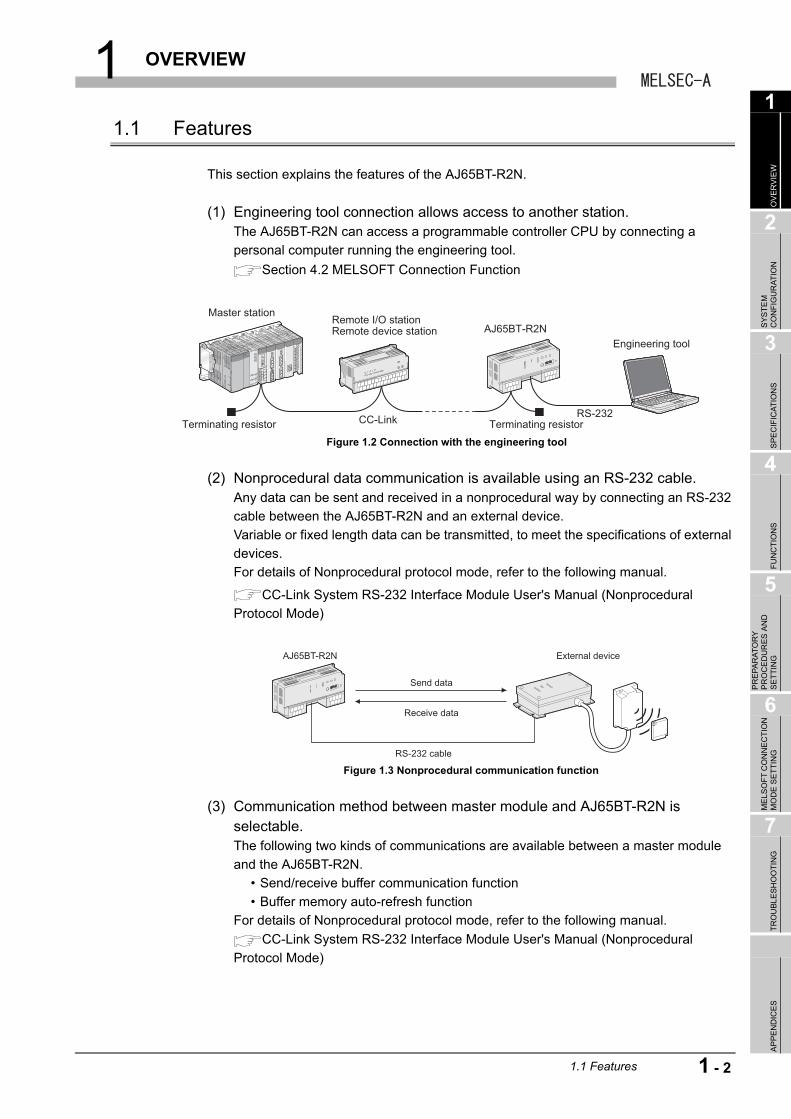
1.1 Features
This section explains the features of the AJ65BT-R2N.
(1) Engineering tool connection allows access to another station.The AJ65BT-R2N can access a programmable controller CPU by connecting a
personal computer running the engineering tool.
Section 4.2 MELSOFT Connection Function
(2) Nonprocedural data communication is available using an RS-232 cable.Any data can be sent and received in a nonprocedural way by connecting an RS-232
cable between the AJ65BT-R2N and an external device.
Variable or fixed length data can be transmitted, to meet the specifications of external
devices.
For details of Nonprocedural protocol mode, refer to the following manual.
CC-Link System RS-232 Interface Module User's Manual (Nonprocedural
Protocol Mode)
(3) Communication method between master module and AJ65BT-R2N is selectable.The following two kinds of communications are available between a master module
and the AJ65BT-R2N.
• Send/receive buffer communication function
• Buffer memory auto-refresh function
For details of Nonprocedural protocol mode, refer to the following manual.
CC-Link System RS-232 Interface Module User's Manual (Nonprocedural
Protocol Mode)
Figure 1.2 Connection with the engineering tool
Figure 1.3 Nonprocedural communication function
AJ65BT-R2NMaster station
Terminating resistor Terminating resistorCC-Link
Remote I/O stationRemote device station
RS-232
Engineering tool
AJ65BT-R2N
Send data
Receive data
RS-232 cable
External device
1.1 Features
1 - 2
1 OVERVIEW
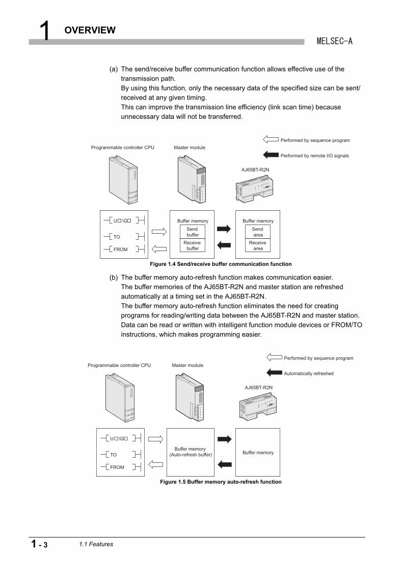
(a) The send/receive buffer communication function allows effective use of the
transmission path.
By using this function, only the necessary data of the specified size can be sent/
received at any given timing.
This can improve the transmission line efficiency (link scan time) because
unnecessary data will not be transferred.
(b) The buffer memory auto-refresh function makes communication easier.
The buffer memories of the AJ65BT-R2N and master station are refreshed
automatically at a timing set in the AJ65BT-R2N.
The buffer memory auto-refresh function eliminates the need for creating
programs for reading/writing data between the AJ65BT-R2N and master station.
Data can be read or written with intelligent function module devices or FROM/TO
instructions, which makes programming easier.
Figure 1.4 Send/receive buffer communication function
Figure 1.5 Buffer memory auto-refresh function
AJ65BT-R2N
Programmable controller CPU Master module
Performed by sequence program
U \G Buffer memory
Send buffer
Receive buffer
Buffer memory
Send area
Receive area
TO
FROM
Performed by remote I/O signals
AJ65BT-R2N
Programmable controller CPU Master module
Performed by sequence program
U \G
Buffer memory (Auto-refresh buffer) Buffer memoryTO
FROM
Automatically refreshed
1 - 3 1.1 Features
1 OVERVIEW
1
OV
ER
VIE
W
2
SY
ST
EM
C
ON
FIG
UR
AT
ION
3
SP
EC
IFIC
AT
ION
S
4
FU
NC
TIO
NS
5
PR
EP
AR
AT
OR
Y
PR
OC
ED
UR
ES
AN
D
SE
TT
ING
6
ME
LSO
FT
CO
NN
EC
TIO
N
MO
DE
SE
TT
ING
7
TR
OU
BL
ES
HO
OT
ING
AP
PE
ND
ICE
S
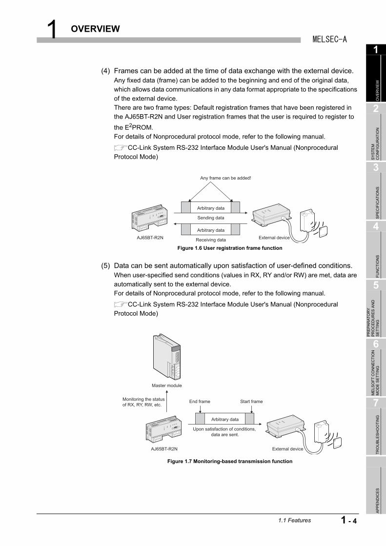
(4) Frames can be added at the time of data exchange with the external device.Any fixed data (frame) can be added to the beginning and end of the original data,
which allows data communications in any data format appropriate to the specifications
of the external device.
There are two frame types: Default registration frames that have been registered in
the AJ65BT-R2N and User registration frames that the user is required to register to
the E2PROM.
For details of Nonprocedural protocol mode, refer to the following manual.
CC-Link System RS-232 Interface Module User's Manual (Nonprocedural
Protocol Mode)
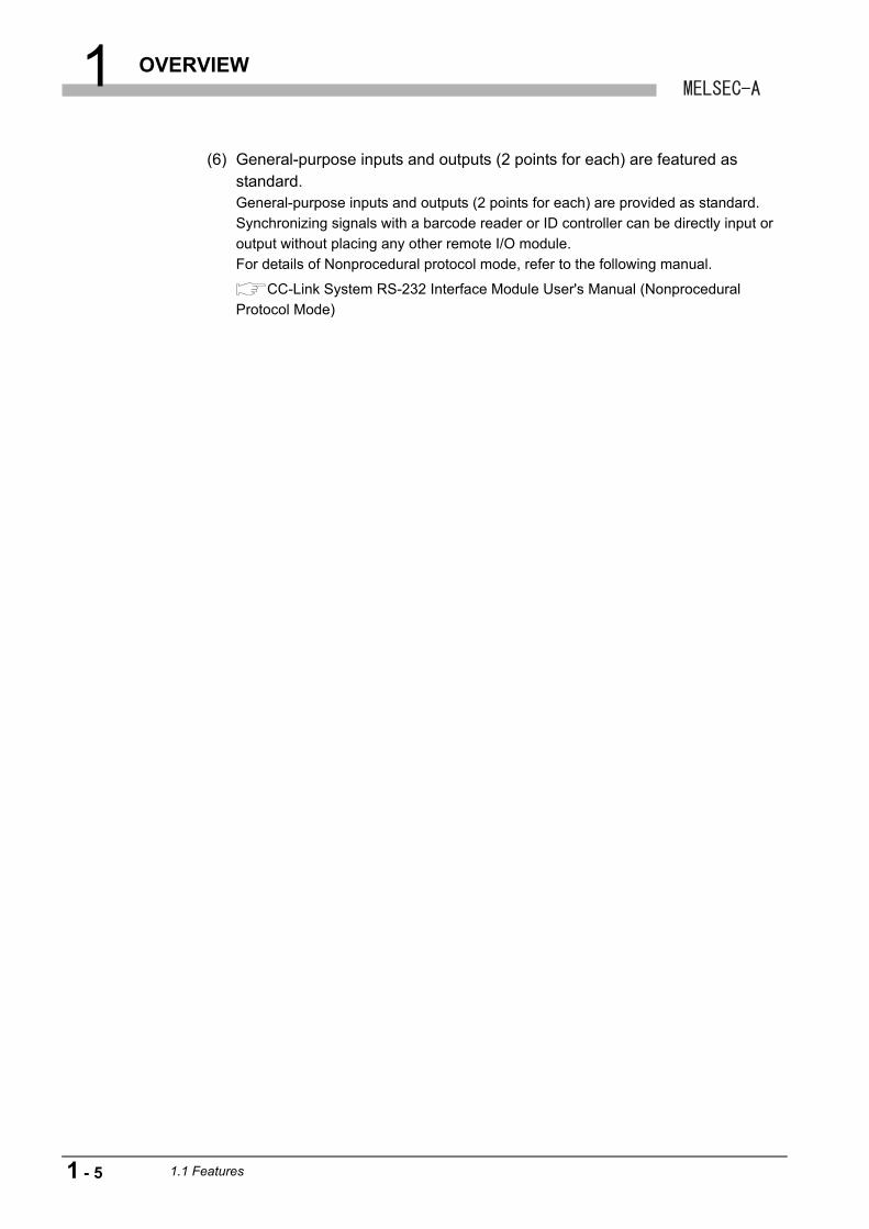
(5) Data can be sent automatically upon satisfaction of user-defined conditions.When user-specified send conditions (values in RX, RY and/or RW) are met, data are
automatically sent to the external device.
For details of Nonprocedural protocol mode, refer to the following manual.
CC-Link System RS-232 Interface Module User's Manual (Nonprocedural
Protocol Mode)
Figure 1.6 User registration frame function
Figure 1.7 Monitoring-based transmission function
AJ65BT-R2N External device
Any frame can be added!
Arbitrary data
Sending data
Arbitrary data
Receiving data
AJ65BT-R2N External device
Arbitrary data
End frame Start frame
Upon satisfaction of conditions, data are sent.
Master module
Monitoring the status of RX, RY, RW, etc.
1.1 Features
1 - 4
1 OVERVIEW
(6) General-purpose inputs and outputs (2 points for each) are featured as standard.General-purpose inputs and outputs (2 points for each) are provided as standard.
Synchronizing signals with a barcode reader or ID controller can be directly input or
output without placing any other remote I/O module.
For details of Nonprocedural protocol mode, refer to the following manual.
CC-Link System RS-232 Interface Module User's Manual (Nonprocedural
Protocol Mode)
1 - 5 1.1 Features
2 SYSTEM CONFIGURATION
1
OV
ER
VIE
W
2
SY
ST
EM
C
ON
FIG
UR
AT
ION
3
SP
EC
IFIC
AT
ION
S
4
FU
NC
TIO
NS
5
PR
EP
AR
AT
OR
Y
PR
OC
ED
UR
ES
AN
D
SE
TT
ING
6
ME
LSO
FT
CO
NN
EC
TIO
N
MO
DE
SE
TT
ING
7
TR
OU
BL
ES
HO
OT
ING
AP
PE
ND
ICE
S
CHAPTER 2 SYSTEM CONFIGURATION
2.1 System Configuration
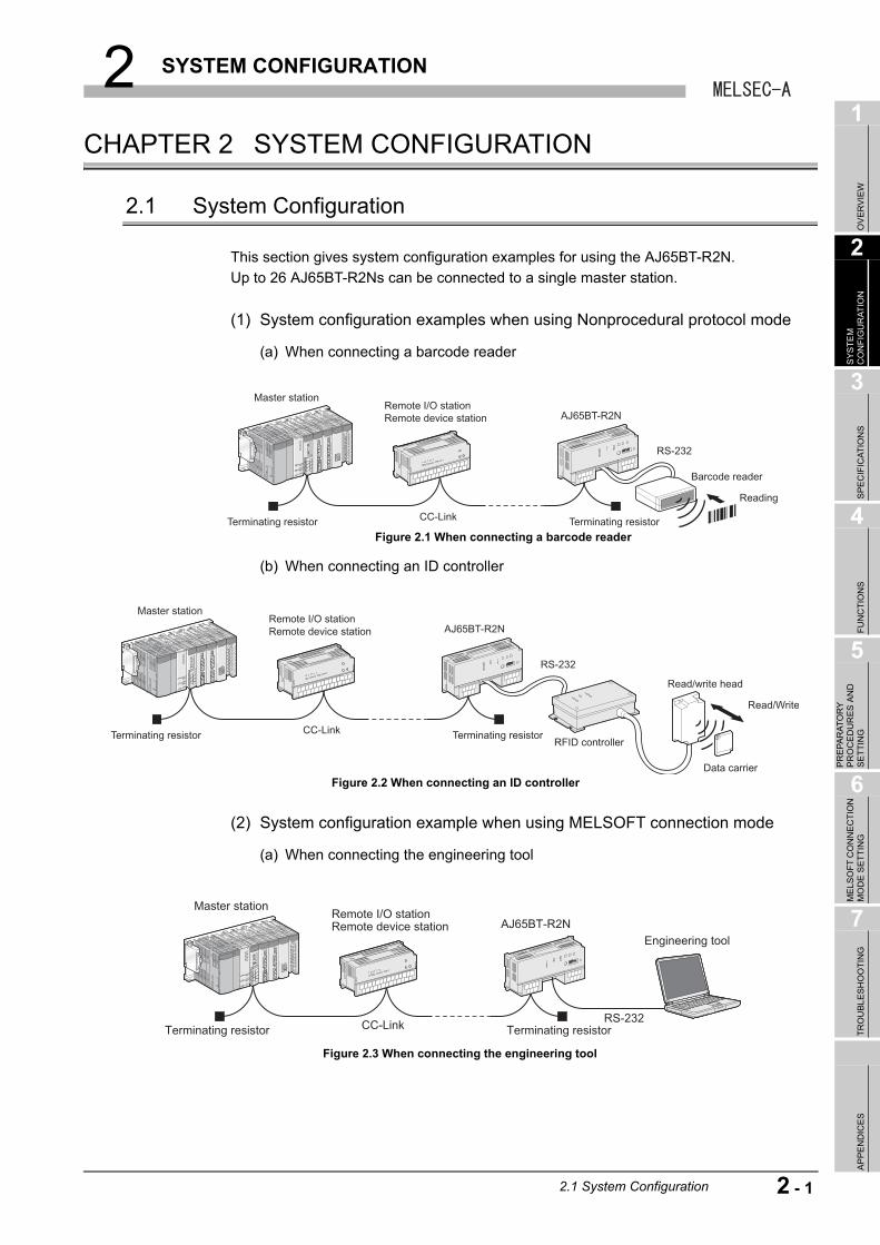
This section gives system configuration examples for using the AJ65BT-R2N.
Up to 26 AJ65BT-R2Ns can be connected to a single master station.
(1) System configuration examples when using Nonprocedural protocol mode
(a) When connecting a barcode reader
(b) When connecting an ID controller
(2) System configuration example when using MELSOFT connection mode
(a) When connecting the engineering tool
Figure 2.1 When connecting a barcode reader
Figure 2.2 When connecting an ID controller
Figure 2.3 When connecting the engineering tool
AJ65BT-R2N
Master station
Terminating resistor Terminating resistorCC-Link
Remote I/O stationRemote device station
RS-232
Barcode reader
Reading
AJ65BT-R2N
Master station
Terminating resistor Terminating resistorCC-Link
Remote I/O stationRemote device station
RS-232
Read/write head
RFID controller
Read/Write
Data carrier
AJ65BT-R2NMaster station
Terminating resistor Terminating resistorCC-Link
Remote I/O stationRemote device station
RS-232
Engineering tool
2.1 System Configuration
2 - 1
2 SYSTEM CONFIGURATION
2.2 Applicable System
This section describes applicable systems.
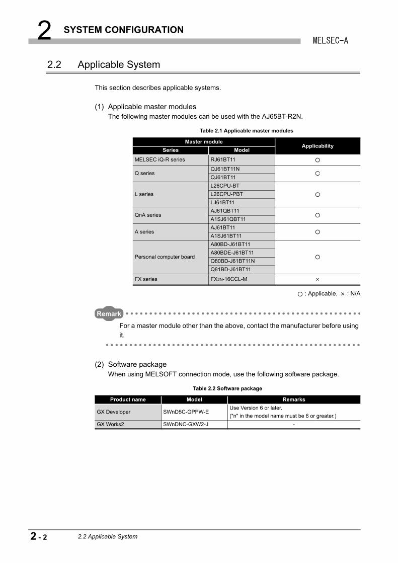
(1) Applicable master modulesThe following master modules can be used with the AJ65BT-R2N.
: Applicable, : N/A
Remark
For a master module other than the above, contact the manufacturer before using
it.
(2) Software packageWhen using MELSOFT connection mode, use the following software package.
Table 2.1 Applicable master modules
Master moduleApplicability
Series Model
MELSEC iQ-R series RJ61BT11
Q seriesQJ61BT11N
QJ61BT11
L series
L26CPU-BT
L26CPU-PBT
LJ61BT11
QnA seriesAJ61QBT11
A1SJ61QBT11
A seriesAJ61BT11
A1SJ61BT11
Personal computer board
A80BD-J61BT11
A80BDE-J61BT11
Q80BD-J61BT11N
Q81BD-J61BT11
FX series FX2N-16CCL-M
Table 2.2 Software package
Product name Model Remarks
GX Developer SWnD5C-GPPW-EUse Version 6 or later.
("n" in the model name must be 6 or greater.)
GX Works2 SWnDNC-GXW2-J -
2 - 2 2.2 Applicable System
2 SYSTEM CONFIGURATION
1
OV
ER
VIE
W
2
SY
ST
EM
C
ON
FIG
UR
AT
ION
3
SP
EC
IFIC
AT
ION
S
4
FU
NC
TIO
NS
5
PR
EP
AR
AT
OR
Y
PR
OC
ED
UR
ES
AN
D
SE
TT
ING
6
ME
LSO
FT
CO
NN
EC
TIO
N
MO
DE
SE
TT
ING
7
TR
OU
BL
ES
HO
OT
ING
AP
PE
ND
ICE
S
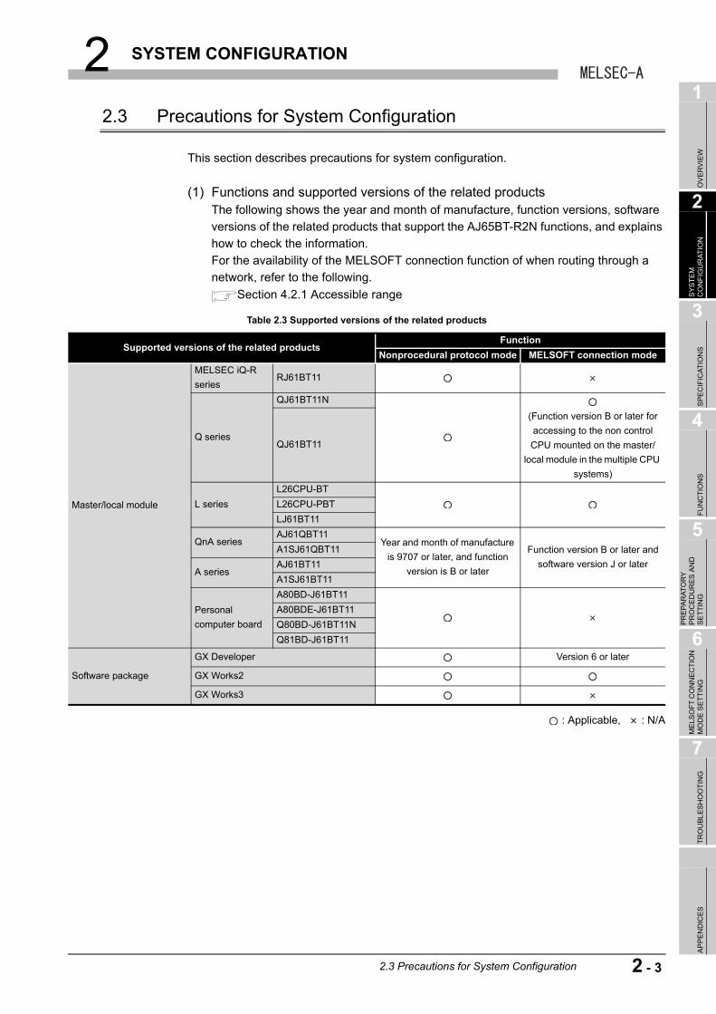
2.3 Precautions for System Configuration
This section describes precautions for system configuration.
(1) Functions and supported versions of the related productsThe following shows the year and month of manufacture, function versions, software
versions of the related products that support the AJ65BT-R2N functions, and explains
how to check the information.
For the availability of the MELSOFT connection function of when routing through a
network, refer to the following.
Section 4.2.1 Accessible range
: Applicable, : N/A
Table 2.3 Supported versions of the related products
Supported versions of the related productsFunction
Nonprocedural protocol mode MELSOFT connection mode
Master/local module
MELSEC iQ-R
seriesRJ61BT11
Q series
QJ61BT11N
(Function version B or later for
accessing to the non control
CPU mounted on the master/
local module in the multiple CPU
systems)
QJ61BT11
L series
L26CPU-BT
L26CPU-PBT
LJ61BT11
QnA seriesAJ61QBT11
Year and month of manufacture
is 9707 or later, and function
version is B or later
Function version B or later and
software version J or later
A1SJ61QBT11
A seriesAJ61BT11
A1SJ61BT11
Personal
computer board
A80BD-J61BT11
A80BDE-J61BT11
Q80BD-J61BT11N
Q81BD-J61BT11
Software package
GX Developer Version 6 or later
GX Works2
GX Works3
2.3 Precautions for System Configuration
2 - 3
2 SYSTEM CONFIGURATION
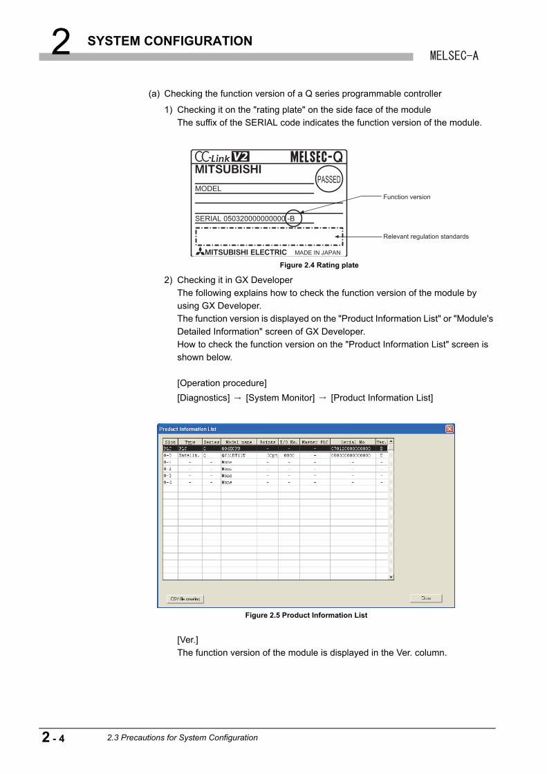
(a) Checking the function version of a Q series programmable controller
1) Checking it on the "rating plate" on the side face of the module
The suffix of the SERIAL code indicates the function version of the module.
2) Checking it in GX Developer
The following explains how to check the function version of the module by
using GX Developer.
The function version is displayed on the "Product Information List" or "Module's
Detailed Information" screen of GX Developer.
How to check the function version on the "Product Information List" screen is
shown below.
[Operation procedure]
[Diagnostics] [System Monitor] [Product Information List]
[Ver.]
The function version of the module is displayed in the Ver. column.
Figure 2.4 Rating plate
Figure 2.5 Product Information List
MADE IN JAPAN
MODEL
SERIAL 050320000000000 -B
Function version
Relevant regulation standards
2 - 4 2.3 Precautions for System Configuration
2 SYSTEM CONFIGURATION
1
OV
ER
VIE
W
2
SY
ST
EM
C
ON
FIG
UR
AT
ION
3
SP
EC
IFIC
AT
ION
S
4
FU
NC
TIO
NS
5
PR
EP
AR
AT
OR
Y
PR
OC
ED
UR
ES
AN
D
SE
TT
ING
6
ME
LSO
FT
CO
NN
EC
TIO
N
MO
DE
SE
TT
ING
7
TR
OU
BL
ES
HO
OT
ING
AP
PE
ND
ICE
S
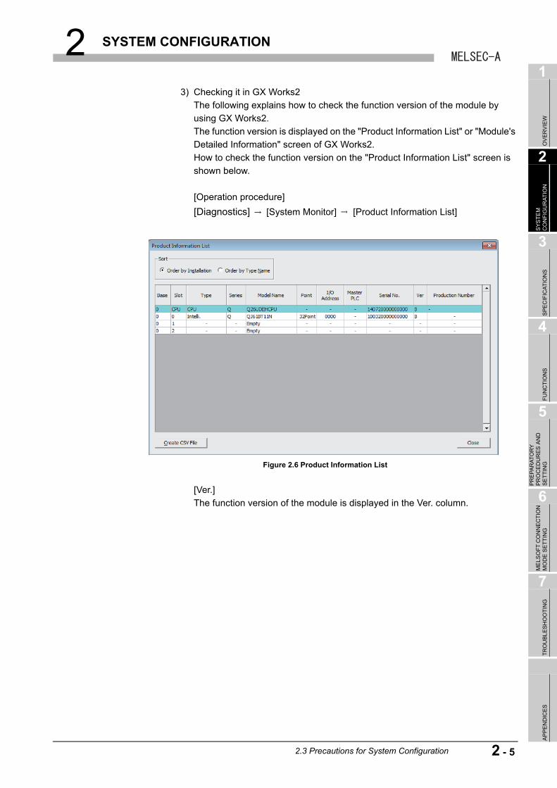
3) Checking it in GX Works2
The following explains how to check the function version of the module by
using GX Works2.
The function version is displayed on the "Product Information List" or "Module's
Detailed Information" screen of GX Works2.
How to check the function version on the "Product Information List" screen is
shown below.
[Operation procedure]
[Diagnostics] [System Monitor] [Product Information List]
[Ver.]
The function version of the module is displayed in the Ver. column.
Figure 2.6 Product Information List
2.3 Precautions for System Configuration
2 - 5
2 SYSTEM CONFIGURATION
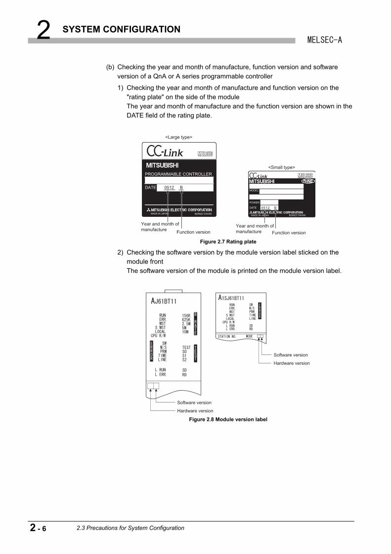
(b) Checking the year and month of manufacture, function version and software
version of a QnA or A series programmable controller
1) Checking the year and month of manufacture and function version on the
"rating plate" on the side of the module
The year and month of manufacture and the function version are shown in the
DATE field of the rating plate.
2) Checking the software version by the module version label sticked on the
module front
The software version of the module is printed on the module version label.
Figure 2.7 Rating plate
Figure 2.8 Module version label
BD992C103H06
DATE
PROGRAMMABLE CONTROLLER
MADE IN JAPAN
MODEL
POWER
DATE
MADE IN JAPAN BD992C154H06
0512 B
0512 B
<Large type>
Year and month of manufacture Function version
Year and month of manufacture Function version
<Small type>
Software version
Hardware version
Software version
Hardware version
2 - 6 2.3 Precautions for System Configuration
2 SYSTEM CONFIGURATION
1
OV
ER
VIE
W
2
SY
ST
EM
C
ON
FIG
UR
AT
ION
3
SP
EC
IFIC
AT
ION
S
4
FU
NC
TIO
NS
5
PR
EP
AR
AT
OR
Y
PR
OC
ED
UR
ES
AN
D
SE
TT
ING
6
ME
LSO
FT
CO
NN
EC
TIO
N
MO
DE
SE
TT
ING
7
TR
OU
BL
ES
HO
OT
ING
AP
PE
ND
ICE
S
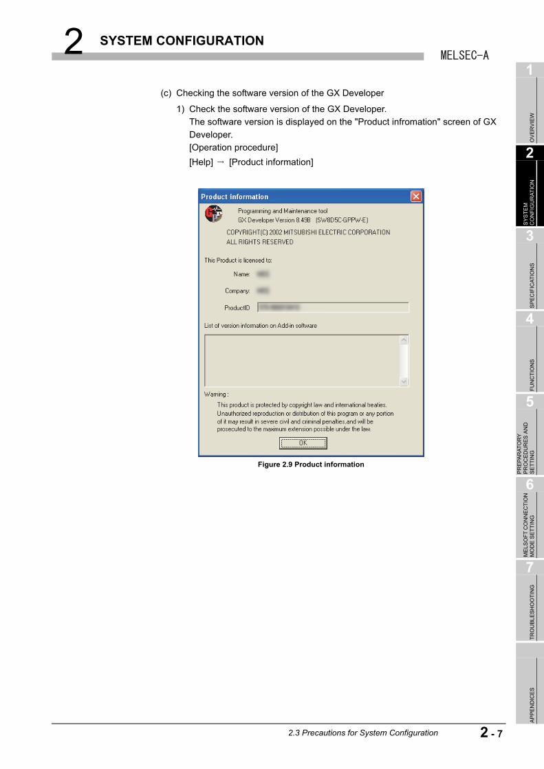
(c) Checking the software version of the GX Developer
1) Check the software version of the GX Developer.
The software version is displayed on the "Product infromation" screen of GX
Developer.
[Operation procedure]
[Help] [Product information]
Figure 2.9 Product information
2.3 Precautions for System Configuration
2 - 7
2 SYSTEM CONFIGURATION
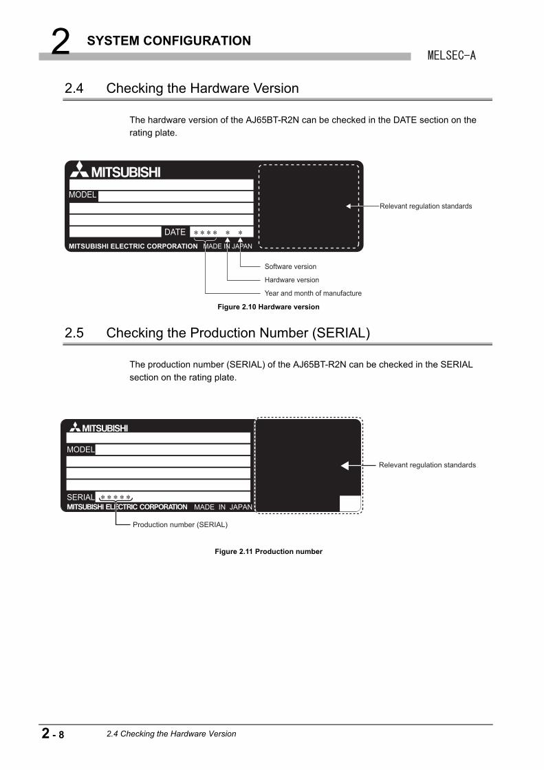
2.4 Checking the Hardware Version
The hardware version of the AJ65BT-R2N can be checked in the DATE section on the
rating plate.
2.5 Checking the Production Number (SERIAL)
The production number (SERIAL) of the AJ65BT-R2N can be checked in the SERIAL
section on the rating plate.
Figure 2.10 Hardware version
Figure 2.11 Production number
Software version
Relevant regulation standards
Hardware version
Year and month of manufacture
MODEL
SERIALMADE IN JAPAN
Production number (SERIAL)
Relevant regulation standards
2 - 8 2.4 Checking the Hardware Version
3 SPECIFICATIONS
1
OV
ER
VIE
W
2
SY
ST
EM
C
ON
FIG
UR
AT
ION
3
SP
EC
IFIC
AT
ION
S
4
FU
NC
TIO
NS
5
PR
EP
AR
AT
OR
Y
PR
OC
ED
UR
ES
AN
D
SE
TT
ING
6
ME
LSO
FT
CO
NN
EC
TIO
N
MO
DE
SE
TT
ING
7
TR
OU
BL
ES
HO
OT
ING
AP
PE
ND
ICE
S
CHAPTER 3 SPECIFICATIONS
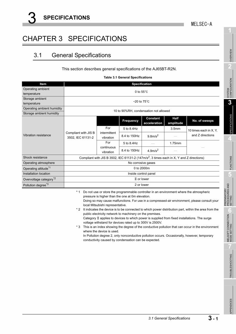
3.1 General Specifications
This section describes general specifications of the AJ65BT-R2N.
* 1 Do not use or store the programmable controller in an environment where the atmospheric pressure is higher than the one at 0m elevation.Doing so may cause malfunctions. For use in a compressed-air environment, please consult your local Mitsubishi representative.
* 2 It indicates the device is to be connected to which power distribution part, within the area from the public electricity network to machinery on the premises.Category applies to devices to which power is supplied from fixed installations. The surge voltage withstand for devices rated up to 300V is 2500V.
* 3 This is an index showing the degree of the conductive pollution that can occur in the environment where the device is used.In Pollution degree 2, only nonconductive pollution occurs. Occasionally, however, temporary conductivity caused by condensation can be expected.
Table 3.1 General Specifications
Item Specification
Operating ambient
temperature0 to 55
Storage ambient
temperature-20 to 75
Operating ambient humidity10 to 90%RH, condensation not allowed
Storage ambient humidity
Vibration resistanceCompliant with JIS B
3502, IEC 61131-2
FrequencyConstant
acceleration
Half
amplitudeNo. of sweeps
For
intermittent
vibration
5 to 8.4Hz 3.5mm 10 times each in X, Y,
and Z directions8.4 to 150Hz 9.8m/s2
For
continuous
vibration
5 to 8.4Hz 1.75mm
8.4 to 150Hz 4.9m/s2
Shock resistance Compliant with JIS B 3502, IEC 61131-2 (147m/s2, 3 times each in X, Y and Z directions)
Operating atmosphere No corrosive gases
Operating altitude*1 0 to 2000m
Installation location Inside control panel
Overvoltage category*2 or lower
Pollution degree*3 2 or lower
3.1 General Specifications
3 - 1
3 SPECIFICATIONS
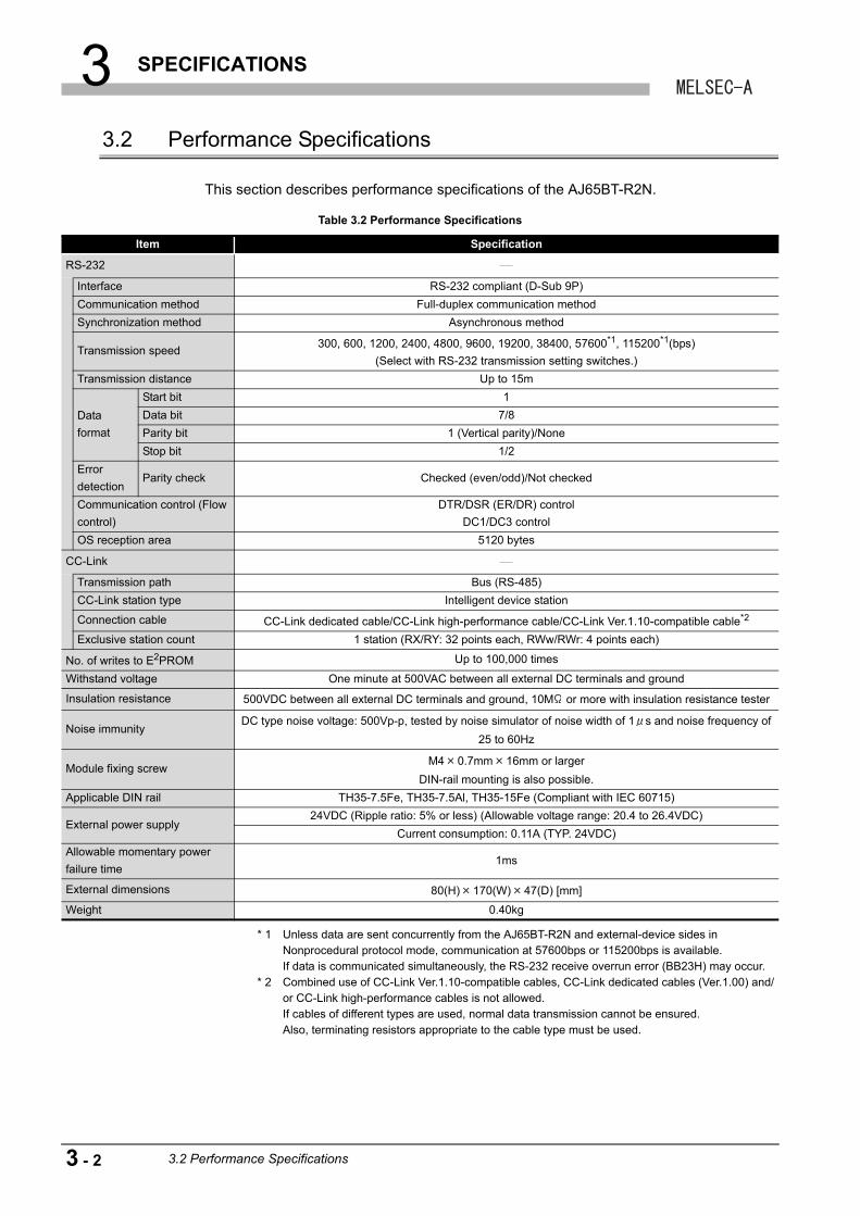
3.2 Performance Specifications
This section describes performance specifications of the AJ65BT-R2N.
* 1 Unless data are sent concurrently from the AJ65BT-R2N and external-device sides in Nonprocedural protocol mode, communication at 57600bps or 115200bps is available.If data is communicated simultaneously, the RS-232 receive overrun error (BB23H) may occur.
* 2 Combined use of CC-Link Ver.1.10-compatible cables, CC-Link dedicated cables (Ver.1.00) and/or CC-Link high-performance cables is not allowed.If cables of different types are used, normal data transmission cannot be ensured.Also, terminating resistors appropriate to the cable type must be used.
Table 3.2 Performance Specifications
Item Specification
RS-232
Interface RS-232 compliant (D-Sub 9P)
Communication method Full-duplex communication method
Synchronization method Asynchronous method
Transmission speed300, 600, 1200, 2400, 4800, 9600, 19200, 38400, 57600*1, 115200*1(bps)
(Select with RS-232 transmission setting switches.)
Transmission distance Up to 15m
Data
format
Start bit 1
Data bit 7/8
Parity bit 1 (Vertical parity)/None
Stop bit 1/2
Error
detectionParity check Checked (even/odd)/Not checked
Communication control (Flow
control)
DTR/DSR (ER/DR) control
DC1/DC3 control
OS reception area 5120 bytes
CC-Link
Transmission path Bus (RS-485)
CC-Link station type Intelligent device station
Connection cable CC-Link dedicated cable/CC-Link high-performance cable/CC-Link Ver.1.10-compatible cable*2
Exclusive station count 1 station (RX/RY: 32 points each, RWw/RWr: 4 points each)
No. of writes to E2PROM Up to 100,000 times
Withstand voltage One minute at 500VAC between all external DC terminals and ground
Insulation resistance 500VDC between all external DC terminals and ground, 10M or more with insulation resistance tester
Noise immunityDC type noise voltage: 500Vp-p, tested by noise simulator of noise width of 1 s and noise frequency of
25 to 60Hz
Module fixing screwM4 0.7mm 16mm or larger
DIN-rail mounting is also possible.
Applicable DIN rail TH35-7.5Fe, TH35-7.5Al, TH35-15Fe (Compliant with IEC 60715)
External power supply24VDC (Ripple ratio: 5% or less) (Allowable voltage range: 20.4 to 26.4VDC)
Current consumption: 0.11A (TYP. 24VDC)
Allowable momentary power
failure time1ms
External dimensions 80(H) 170(W) 47(D) [mm]
Weight 0.40kg
3 - 2 3.2 Performance Specifications
3 SPECIFICATIONS
1
OV
ER
VIE
W
2
SY
ST
EM
C
ON
FIG
UR
AT
ION
3
SP
EC
IFIC
AT
ION
S
4
FU
NC
TIO
NS
5
PR
EP
AR
AT
OR
Y
PR
OC
ED
UR
ES
AN
D
SE
TT
ING
6
ME
LSO
FT
CO
NN
EC
TIO
N
MO
DE
SE
TT
ING
7
TR
OU
BL
ES
HO
OT
ING
AP
PE
ND
ICE
S
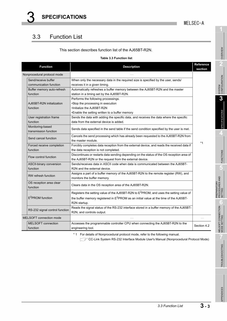
3.3 Function List
This section describes function list of the AJ65BT-R2N.
* 1 For details of Nonprocedural protocol mode, refer to the following manual.
CC-Link System RS-232 Interface Module User's Manual (Nonprocedural Protocol Mode)
Table 3.3 Function list
Function DescriptionReference
section
Nonprocedural protocol mode
*1
Send/receive buffer
communication function
When only the necessary data in the required size is specified by the user, sends/
receives it in a given timing.
Buffer memory auto-refresh
function
Automatically refreshes a buffer memory between the AJ65BT-R2N and the master
station in a timing set by the AJ65BT-R2N.
AJ65BT-R2N initialization
function
Performs the following processings.
•Stop the processing in execution
•Initialize the AJ65BT-R2N
•Enable the setting written to a buffer memory
User registration frame
function
Sends the data with adding the specific data, and receives the data where the specific
data from the external device is added.
Monitoring-based
transmission functionSends data specified in the send table if the send condition specified by the user is met.
Send cancel functionCancels the send processing which has already been requested to the AJ65BT-R2N from
the master module.
Forced receive completion
function
Forcibly completes data reception from the external device, and reads the received data if
the data reception is not completed.
Flow control functionDiscontinues or restarts data sending depending on the status of the OS reception area of
the AJ65BT-R2N or the request from the external device.
ASCII-binary conversion
function
Sends/receives data in ASCII code when data is communicated between the AJ65BT-
R2N and the external device.
RW refresh functionAssigns a part of a buffer memory of the AJ65BT-R2N to the remote register (RW), and
monitors the buffer memory.
OS reception area clear
functionClears data in the OS reception area of the AJ65BT-R2N.
E2PROM function
Registers the setting value of the AJ65BT-R2N to E2PROM, and uses the setting value of
the buffer memory registered in E2PROM as an initial value at the time of the AJ65BT-
R2N startup.
RS-232 signal control functionReads the signal status of the RS-232 interface stored in a buffer memory of the AJ65BT-
R2N, and controls output.
MELSOFT connection mode MELSOFT connection
function
Accesses the programmable controller CPU when connecting the AJ65BT-R2N to the
engineering tool.Section 4.2
3.3 Function List
3 - 3
3 SPECIFICATIONS
3.4 CC-Link Dedicated Cable Specifications
In CC-Link systems, use CC-Link dedicated cables.
The performance of the CC-Link system cannot be guaranteed when any other than
dedicated CC-Link cables is used.
For more information, visit the following website.
CC-Link Partner Association (www.cc-link.org)
Remark
Refer to the CC-Link Cable Wiring Manual issued by the CC-Link Partner
Association.
3 - 4 3.4 CC-Link Dedicated Cable Specifications
3 SPECIFICATIONS
1
OV
ER
VIE
W
2
SY
ST
EM
C
ON
FIG
UR
AT
ION
3
SP
EC
IFIC
AT
ION
S
4
FU
NC
TIO
NS
5
PR
EP
AR
AT
OR
Y
PR
OC
ED
UR
ES
AN
D
SE
TT
ING
6
ME
LSO
FT
CO
NN
EC
TIO
N
MO
DE
SE
TT
ING
7
TR
OU
BL
ES
HO
OT
ING
AP
PE
ND
ICE
S
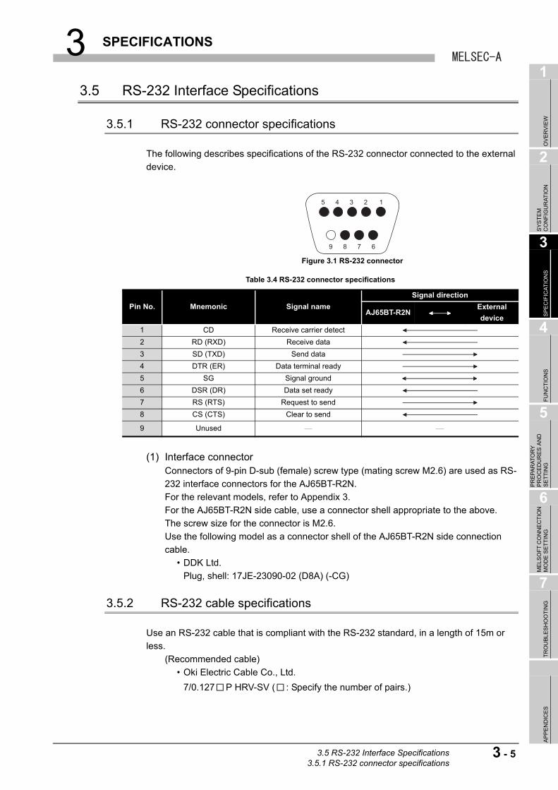
3.5 RS-232 Interface Specifications
3.5.1 RS-232 connector specifications
The following describes specifications of the RS-232 connector connected to the external
device.
(1) Interface connectorConnectors of 9-pin D-sub (female) screw type (mating screw M2.6) are used as RS-
232 interface connectors for the AJ65BT-R2N.
For the relevant models, refer to Appendix 3.
For the AJ65BT-R2N side cable, use a connector shell appropriate to the above.
The screw size for the connector is M2.6.
Use the following model as a connector shell of the AJ65BT-R2N side connection
cable.
• DDK Ltd.
Plug, shell: 17JE-23090-02 (D8A) (-CG)
3.5.2 RS-232 cable specifications
Use an RS-232 cable that is compliant with the RS-232 standard, in a length of 15m or
less.
(Recommended cable)
• Oki Electric Cable Co., Ltd.
7/0.127 P HRV-SV ( : Specify the number of pairs.)
Figure 3.1 RS-232 connector
Table 3.4 RS-232 connector specifications
Pin No. Mnemonic Signal name
Signal direction
AJ65BT-R2NExternal
device
1 CD Receive carrier detect
2 RD (RXD) Receive data
3 SD (TXD) Send data
4 DTR (ER) Data terminal ready
5 SG Signal ground
6 DSR (DR) Data set ready
7 RS (RTS) Request to send
8 CS (CTS) Clear to send
9 Unused
5 4 3 2
9 8 7 6
1
3.5 RS-232 Interface Specifications3.5.1 RS-232 connector specifications
3 - 5
3 SPECIFICATIONS
3.6 General-purpose I/O Specifications
For general-purpose I/O specifications of the AJ65BT-R2N, refer to the following manual.
CC-Link System RS-232 Interface Module User's Manual (Nonprocedural Protocol
Mode)
3 - 6 3.6 General-purpose I/O Specifications
3 SPECIFICATIONS
1
OV
ER
VIE
W
2
SY
ST
EM
C
ON
FIG
UR
AT
ION
3
SP
EC
IFIC
AT
ION
S
4
FU
NC
TIO
NS
5
PR
EP
AR
AT
OR
Y
PR
OC
ED
UR
ES
AN
D
SE
TT
ING
6
ME
LSO
FT
CO
NN
EC
TIO
N
MO
DE
SE
TT
ING
7
TR
OU
BL
ES
HO
OT
ING
AP
PE
ND
ICE
S
3.7 Remote I/O and Remote Register
The following describes the remote I/O and remote register of the AJ65BT-R2N.
3.7.1 Remote I/O list
The remote I/O list of the AJ65BT-R2N is shown below.
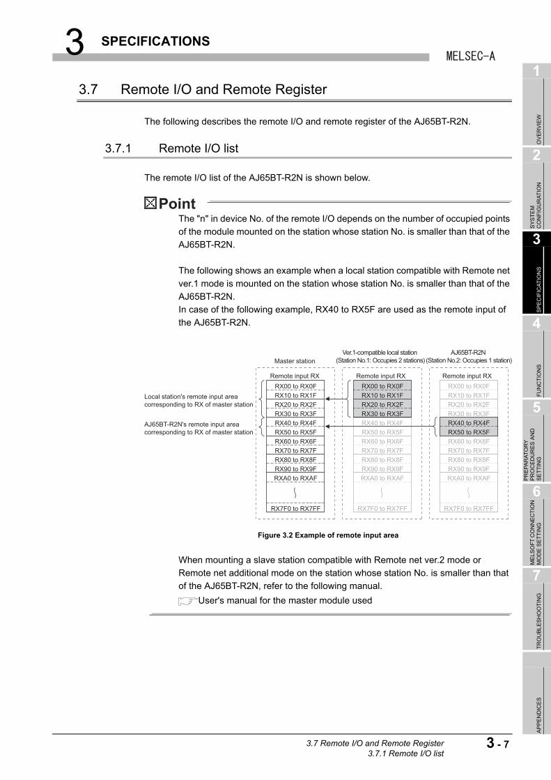
The "n" in device No. of the remote I/O depends on the number of occupied points
of the module mounted on the station whose station No. is smaller than that of the
AJ65BT-R2N.
The following shows an example when a local station compatible with Remote net
ver.1 mode is mounted on the station whose station No. is smaller than that of the
AJ65BT-R2N.
In case of the following example, RX40 to RX5F are used as the remote input of
the AJ65BT-R2N.
When mounting a slave station compatible with Remote net ver.2 mode or
Remote net additional mode on the station whose station No. is smaller than that
of the AJ65BT-R2N, refer to the following manual.
User's manual for the master module used
Figure 3.2 Example of remote input area
Local station's remote input area corresponding to RX of master station
AJ65BT-R2N's remote input area corresponding to RX of master station
Master stationVer.1-compatible local station
(Station No.1: Occupies 2 stations)AJ65BT-R2N
(Station No.2: Occupies 1 station)
Remote input RX Remote input RX Remote input RX
RX00 to RX0FRX10 to RX1FRX20 to RX2FRX30 to RX3FRX40 to RX4FRX50 to RX5FRX60 to RX6FRX70 to RX7FRX80 to RX8FRX90 to RX9FRXA0 to RXAF
RX7F0 to RX7FF
RX00 to RX0FRX10 to RX1FRX20 to RX2FRX30 to RX3FRX40 to RX4FRX50 to RX5FRX60 to RX6FRX70 to RX7FRX80 to RX8FRX90 to RX9FRXA0 to RXAF
RX7F0 to RX7FF
RX00 to RX0FRX10 to RX1FRX20 to RX2FRX30 to RX3FRX40 to RX4FRX50 to RX5FRX60 to RX6FRX70 to RX7FRX80 to RX8FRX90 to RX9FRXA0 to RXAF
RX7F0 to RX7FF
3.7 Remote I/O and Remote Register3.7.1 Remote I/O list
3 - 7
3 SPECIFICATIONS
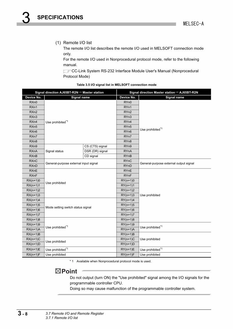
(1) Remote I/O listThe remote I/O list describes the remote I/O used in MELSOFT connection mode
only.
For the remote I/O used in Nonprocedural protocol mode, refer to the following
manual.
CC-Link System RS-232 Interface Module User's Manual (Nonprocedural
Protocol Mode)
* 1 Available when Nonprocedural protocol mode is used.
Do not output (turn ON) the "Use prohibited" signal among the I/O signals for the
programmable controller CPU.
Doing so may cause malfunction of the programmable controller system.
Table 3.5 I/O signal list in MELSOFT connection mode
Signal direction AJ65BT-R2N Master station Signal direction Master station AJ65BT-R2N
Device No. Signal name Device No. Signal name
RXn0
Use prohibited*1
RYn0
Use prohibited*1
RXn1 RYn1
RXn2 RYn2
RXn3 RYn3
RXn4 RYn4
RXn5 RYn5
RXn6 RYn6
RXn7 RYn7
RXn8 RYn8
RXn9
Signal status
CS (CTS) signal RYn9
RXnA DSR (DR) signal RYnA
RXnB CD signal RYnB
RXnCGeneral-purpose external input signal
RYnCGeneral-purpose external output signal
RXnD RYnD
RXnE
Use prohibited
RYnE
Use prohibited
RXnF RYnF
RX(n+1)0 RY(n+1)0
RX(n+1)1 RY(n+1)1
RX(n+1)2 RY(n+1)2
RX(n+1)3 RY(n+1)3
RX(n+1)4
Mode setting switch status signal
RY(n+1)4
RX(n+1)5 RY(n+1)5
RX(n+1)6 RY(n+1)6
RX(n+1)7 RY(n+1)7
RX(n+1)8
Use prohibited*1
RY(n+1)8
RX(n+1)9 RY(n+1)9Use prohibited*1
RX(n+1)A RY(n+1)A
RX(n+1)B RY(n+1)B
Use prohibitedRX(n+1)CUse prohibited
RY(n+1)C
RX(n+1)D RY(n+1)D
RX(n+1)E Use prohibited*1 RY(n+1)E Use prohibited*1
RX(n+1)F Use prohibited RY(n+1)F Use prohibited
3 - 8 3.7 Remote I/O and Remote Register3.7.1 Remote I/O list
3 SPECIFICATIONS
1
OV
ER
VIE
W
2
SY
ST
EM
C
ON
FIG
UR
AT
ION
3
SP
EC
IFIC
AT
ION
S
4
FU
NC
TIO
NS
5
PR
EP
AR
AT
OR
Y
PR
OC
ED
UR
ES
AN
D
SE
TT
ING
6
ME
LSO
FT
CO
NN
EC
TIO
N
MO
DE
SE
TT
ING
7
TR
OU
BL
ES
HO
OT
ING
AP
PE
ND
ICE
S
3.7.2 Remote I/O details
The following describes details of the remote I/O of the AJ65BT-R2N.
Only the remote I/O used in MELSOFT connection mode is described.
For the remote I/O used in Nonprocedural protocol mode, refer to the following manual.
CC-Link System RS-232 Interface Module User's Manual (Nonprocedural Protocol
Mode)
(1) Signal status: CS (CTS) signal (RXn9), DSR (DR) signal (RXnA), and CD signal (RXnB)Signal status is used to check the status of the control signals (CS (CTS) signal, DSR
(DR) signal, and CD signal) in RS-232 communication.
(2) General-purpose external output signal (RYnC and RYnD)General-purpose external output signals (RYnC and RYnD) are used to turn ON/OFF
the general-purpose external outputs (YC and YD) of the AJ65BT-R2N.
RYnC corresponds to YC, and RYnD corresponds to YD, respectively.
(3) General-purpose external input signal (RXnC and RXnD)General-purpose external input signals (RXnC and RXnD) are used to check the
status of the general-purpose external inputs (XC and XD) of the AJ65BT-R2N.
General-purpose external input signals (RXnC and RXnD) are indicated by ON/OFF.
RXnC corresponds to XC, and RXnD corresponds to XD, respectively.
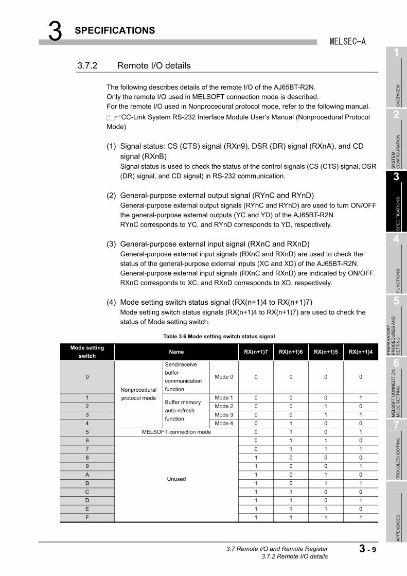
(4) Mode setting switch status signal (RX(n+1)4 to RX(n+1)7)Mode setting switch status signals (RX(n+1)4 to RX(n+1)7) are used to check the
status of Mode setting switch.
Table 3.6 Mode setting switch status signal
Mode setting
switchName RX(n+1)7 RX(n+1)6 RX(n+1)5 RX(n+1)4
0
Nonprocedural
protocol mode
Send/receive
buffer
communication
function
Mode 0 0 0 0 0
1Buffer memory
auto-refresh
function
Mode 1 0 0 0 1
2 Mode 2 0 0 1 0
3 Mode 3 0 0 1 1
4 Mode 4 0 1 0 0
5 MELSOFT connection mode 0 1 0 1
6
Unused
0 1 1 0
7 0 1 1 1
8 1 0 0 0
9 1 0 0 1
A 1 0 1 0
B 1 0 1 1
C 1 1 0 0
D 1 1 0 1
E 1 1 1 0
F 1 1 1 1
3.7 Remote I/O and Remote Register3.7.2 Remote I/O details
3 - 9

3 SPECIFICATIONS
3.7.3 Remote register list
The following describes the remote register list of the AJ65BT-R2N.
The "m" in device No. of the remote register depends on the number of occupied
points of the module mounted on the station whose station No. is smaller than that
of the AJ65BT-R2N.
The following shows an example when a local station compatible with Remote net
ver.1 mode is mounted on the station whose station No. is smaller than that of the
AJ65BT-R2N.
In case of the following example, RWw8 to RWwB are used as the remote register
of the AJ65BT-R2N.
When mounting a slave station compatible with Remote net ver.2 mode or
Remote net additional mode on the station whose station No. is smaller than that
of the AJ65BT-R2N, refer to the following manual.
User's manual for the master module used
Figure 3.3 Example of remote register area
Local station's remote register area corresponding to RWw of master station
AJ65BT-R2N's remote register area corresponding to RWw of master station
Master station
Remote register RWw
Ver.1-compatible local station (Station No.1: Occupies 2 stations)
Remote register RWw
AJ65BT-R2N (Station No.2: Occupies 1 station)
Remote register RWw
RWw0
RWw1
RWw2
RWw3
RWw4
RWw5
RWw6
RWw7
RWw8
RWw9
RWwA
RWwB
RWwC
RWwD
RWwFF
RWw0
RWw1
RWw2
RWw3
RWw4
RWw5
RWw6
RWw7
RWw8
RWw9
RWwA
RWwB
RWwC
RWwD
RWwFF
RWw0
RWw1
RWw2
RWw3
RWw4
RWw5
RWw6
RWw7
RWw8
RWw9
RWwA
RWwB
RWwC
RWwD
RWwFF
3 - 10 3.7 Remote I/O and Remote Register3.7.3 Remote register list
3 SPECIFICATIONS
1
OV
ER
VIE
W
2
SY
ST
EM
C
ON
FIG
UR
AT
ION
3
SP
EC
IFIC
AT
ION
S
4
FU
NC
TIO
NS
5
PR
EP
AR
AT
OR
Y
PR
OC
ED
UR
ES
AN
D
SE
TT
ING
6
ME
LSO
FT
CO
NN
EC
TIO
N
MO
DE
SE
TT
ING
7
TR
OU
BL
ES
HO
OT
ING
AP
PE
ND
ICE
S
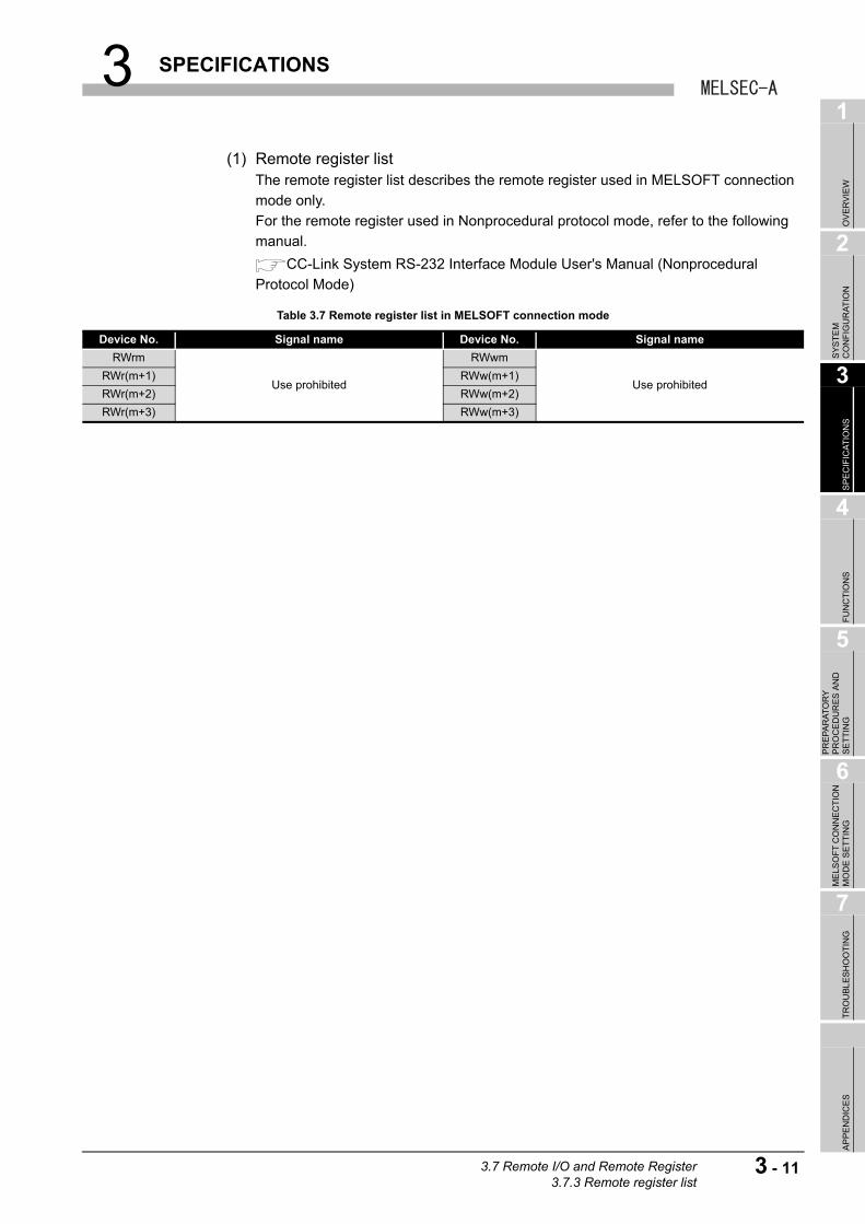
(1) Remote register listThe remote register list describes the remote register used in MELSOFT connection
mode only.
For the remote register used in Nonprocedural protocol mode, refer to the following
manual.
CC-Link System RS-232 Interface Module User's Manual (Nonprocedural
Protocol Mode)
Table 3.7 Remote register list in MELSOFT connection mode
Device No. Signal name Device No. Signal name
RWrm
Use prohibited
RWwm
Use prohibitedRWr(m+1) RWw(m+1)
RWr(m+2) RWw(m+2)
RWr(m+3) RWw(m+3)
3.7 Remote I/O and Remote Register3.7.3 Remote register list
3 - 11

3 SPECIFICATIONS
3.8 Buffer Memory
3.8.1 Buffer memory list
The following describes the buffer memory list.
Contents of set buffer memory of the AJ65BT-R2N can be returned to default by turning
ON power supply of the AJ65BT-R2N again or reset operation.
However, if registering changed contents of buffer memory of the AJ65BT-R2N to the
E2PROM of the AJ65BT-R2N, the initial value of E2PROM will be written when turning ON
power supply of the AJ65BT-R2N.
For details, refer to the following manual.
CC-Link System RS-232 Interface Module User's Manual (Nonprocedural Protocol
Mode)
(1) How buffer memory list is organizedThe following shows how buffer memory list is organized.
Figure 3.4 Organization of list
Table 3.8 Organization of list
No. Name Description
Address The address of buffer memory of the AJ65BT-R2N in hexadecimal or decimal.
Name The name of buffer memory of the AJ65BT-R2N.
Default The value at factory default setting of the AJ65BT-R2N.
Read/Write
Applicability of reading/writing.
•R: Readable only
•W: Writable only
•R/W: Readable and writable
Refresh
Shows which of the master station or the AJ65BT-R2N refreshes the buffer memory value of the
AJ65BT-R2N.
•M: Refresh is performed by the master station
•R2N: Refresh is performed by the AJ65BT-R2N
•Both: Refresh is performed by the master station and the AJ65BT-R2N
Initialization
Shows whether the initialization is necessary or not when changing the buffer memory value of the
AJ65BT-R2N.
•Needed: Initialization is necessary
•Not needed: Initialization is not necessary
E2PROM register
Shows whether contents of buffer memory of the AJ65BT-R2N can be registered to the E2PROM of
the AJ65BT-R2N or not.
•Available: Registration to E2PROM is possible
•N/A: Registration to E2PROM is not possible
Reference section Chapter and section of the detailed description.
R2NR2N AddressAddress
HEX.HEX. DEC.DEC.NameName DefaultDefault RefreshRefresh InitializationInitialization E2PROM PROM
registerregisterReference Reference
sectionsectionRead/Read/WriteWrite
1 2 3 4 5 6 7 8
1 R2N
2
3
4
5
6
7
8
3 - 12 3.8 Buffer Memory3.8.1 Buffer memory list
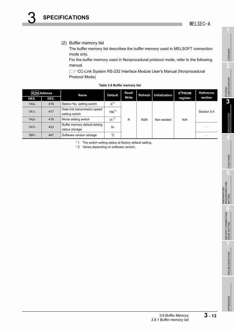
3 SPECIFICATIONS
1
OV
ER
VIE
W
2
SY
ST
EM
C
ON
FIG
UR
AT
ION
3
SP
EC
IFIC
AT
ION
S
4
FU
NC
TIO
NS
5
PR
EP
AR
AT
OR
Y
PR
OC
ED
UR
ES
AN
D
SE
TT
ING
6
ME
LSO
FT
CO
NN
EC
TIO
N
MO
DE
SE
TT
ING
7
TR
OU
BL
ES
HO
OT
ING
AP
PE
ND
ICE
S
(2) Buffer memory listThe buffer memory list describes the buffer memory used in MELSOFT connection
mode only.
For the buffer memory used in Nonprocedural protocol mode, refer to the following
manual.
CC-Link System RS-232 Interface Module User's Manual (Nonprocedural
Protocol Mode)
* 1 The switch setting status at factory default setting. * 2 Varies depending on software version.
Table 3.9 Buffer memory list
AddressName Default
Read/
WriteRefresh Initialization
E2PROM
register
Reference
sectionHEX. DEC.
1A0H 416 Station No. setting switch 0*1
R R2N Not needed N/A
Section 5.41A1H 417Data link transmission speed
setting switch156*1
1A2H 418 Mode setting switch 0H*1
1A7H 423Buffer memory default setting
status storage0H
1BFH 447 Software version storage *2
R2NR2N
3.8 Buffer Memory3.8.1 Buffer memory list
3 - 13
4 FUNCTIONS
CHAPTER 4 FUNCTIONS
4.1 Selecting Mode and Function(s)
This section explains how to select the mode and function(s) of the AJ65BT-R2N.
The modes of the AJ65BT-R2N are shown below.
Select a mode that is suitable for the intended use.
(1) Communication with nonprocedural protocolUse the Nonprocedural protocol mode for exchanging data by nonprocedural protocol
through an RS-232 cable connected between the AJ65BT-R2N and external device.
For selection of functions used in Nonprocedural protocol mode, refer to the following.
CC-Link System RS-232 Interface Module User's Manual (Nonprocedural
Protocol Mode)
(2) Connection with the engineering toolUse the MELSOFT connection function when accessing a programmable controller
CPU via the AJ65BT-R2N from a personal computer where the engineering tool is
installed.
For the MELSOFT connection function, refer to the following.
Section 4.2 MELSOFT Connection Function
(3) Hardware testPerform the hardware test when checking whether a single unit of the AJ65BT-R2N
operates normally or not.
For the hardware test, refer to the following.
Section 5.5.1 Hardware test
4 - 1 4.1 Selecting Mode and Function(s)
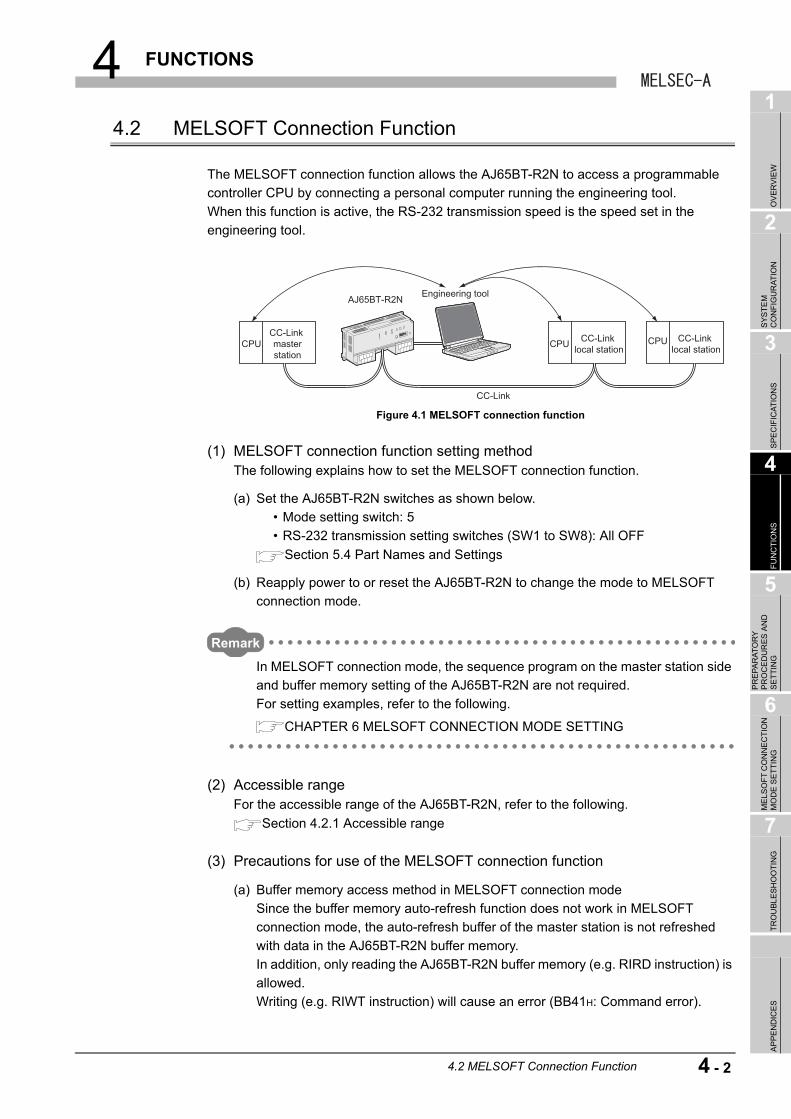
4 FUNCTIONS
1
OV
ER
VIE
W
2
SY
ST
EM
C
ON
FIG
UR
AT
ION
3
SP
EC
IFIC
AT
ION
S
4
FU
NC
TIO
NS
5
PR
EP
AR
AT
OR
Y
PR
OC
ED
UR
ES
AN
D
SE
TT
ING
6
ME
LSO
FT
CO
NN
EC
TIO
N
MO
DE
SE
TT
ING
7
TR
OU
BL
ES
HO
OT
ING
AP
PE
ND
ICE
S
4.2 MELSOFT Connection Function
The MELSOFT connection function allows the AJ65BT-R2N to access a programmable
controller CPU by connecting a personal computer running the engineering tool.
When this function is active, the RS-232 transmission speed is the speed set in the
engineering tool.
(1) MELSOFT connection function setting methodThe following explains how to set the MELSOFT connection function.
(a) Set the AJ65BT-R2N switches as shown below.
• Mode setting switch: 5
• RS-232 transmission setting switches (SW1 to SW8): All OFF
Section 5.4 Part Names and Settings
(b) Reapply power to or reset the AJ65BT-R2N to change the mode to MELSOFT
connection mode.
Remark
In MELSOFT connection mode, the sequence program on the master station side
and buffer memory setting of the AJ65BT-R2N are not required.
For setting examples, refer to the following.
CHAPTER 6 MELSOFT CONNECTION MODE SETTING
(2) Accessible rangeFor the accessible range of the AJ65BT-R2N, refer to the following.
Section 4.2.1 Accessible range
(3) Precautions for use of the MELSOFT connection function
(a) Buffer memory access method in MELSOFT connection mode
Since the buffer memory auto-refresh function does not work in MELSOFT
connection mode, the auto-refresh buffer of the master station is not refreshed
with data in the AJ65BT-R2N buffer memory.
In addition, only reading the AJ65BT-R2N buffer memory (e.g. RIRD instruction) is
allowed.
Writing (e.g. RIWT instruction) will cause an error (BB41H: Command error).
Figure 4.1 MELSOFT connection function
AJ65BT-R2N
CC-Link
CC-Link masterstation
CPU CC-Link local stationCPU CC-Link
local stationCPU
Engineering tool
4.2 MELSOFT Connection Function
4 - 2
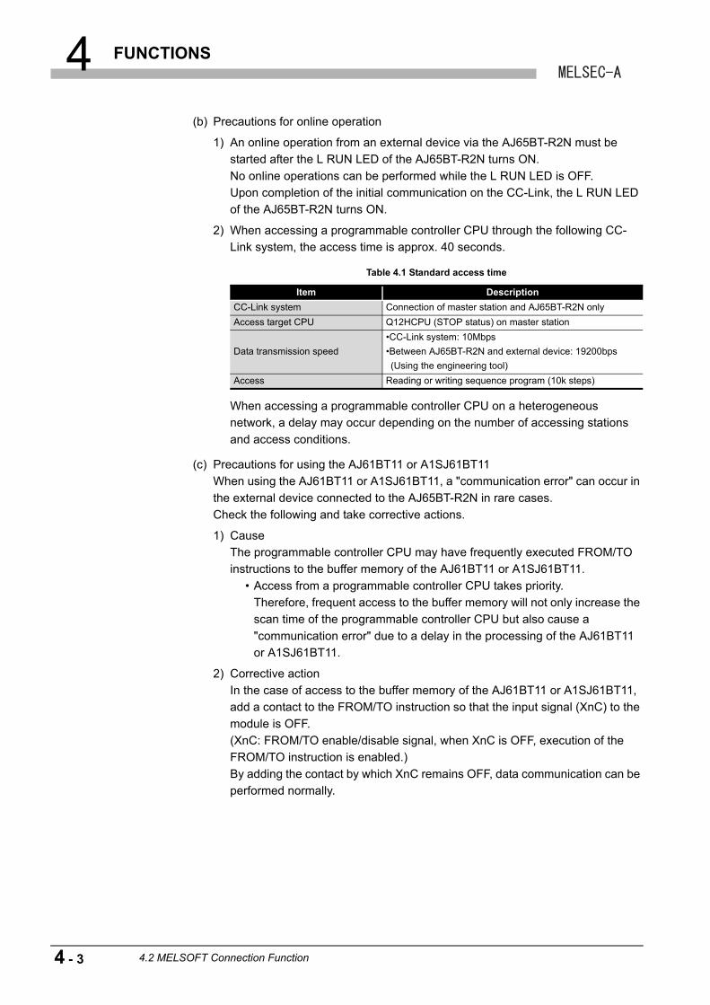
4 FUNCTIONS
(b) Precautions for online operation
1) An online operation from an external device via the AJ65BT-R2N must be
started after the L RUN LED of the AJ65BT-R2N turns ON.
No online operations can be performed while the L RUN LED is OFF.
Upon completion of the initial communication on the CC-Link, the L RUN LED
of the AJ65BT-R2N turns ON.
2) When accessing a programmable controller CPU through the following CC-
Link system, the access time is approx. 40 seconds.
When accessing a programmable controller CPU on a heterogeneous
network, a delay may occur depending on the number of accessing stations
and access conditions.
(c) Precautions for using the AJ61BT11 or A1SJ61BT11
When using the AJ61BT11 or A1SJ61BT11, a "communication error" can occur in
the external device connected to the AJ65BT-R2N in rare cases.
Check the following and take corrective actions.
1) Cause
The programmable controller CPU may have frequently executed FROM/TO
instructions to the buffer memory of the AJ61BT11 or A1SJ61BT11.
• Access from a programmable controller CPU takes priority.
Therefore, frequent access to the buffer memory will not only increase the
scan time of the programmable controller CPU but also cause a
"communication error" due to a delay in the processing of the AJ61BT11
or A1SJ61BT11.
2) Corrective action
In the case of access to the buffer memory of the AJ61BT11 or A1SJ61BT11,
add a contact to the FROM/TO instruction so that the input signal (XnC) to the
module is OFF.
(XnC: FROM/TO enable/disable signal, when XnC is OFF, execution of the
FROM/TO instruction is enabled.)
By adding the contact by which XnC remains OFF, data communication can be
performed normally.
Table 4.1 Standard access time
Item Description
CC-Link system Connection of master station and AJ65BT-R2N only
Access target CPU Q12HCPU (STOP status) on master station
Data transmission speed
•CC-Link system: 10Mbps
•Between AJ65BT-R2N and external device: 19200bps
(Using the engineering tool)
Access Reading or writing sequence program (10k steps)
4 - 3 4.2 MELSOFT Connection Function
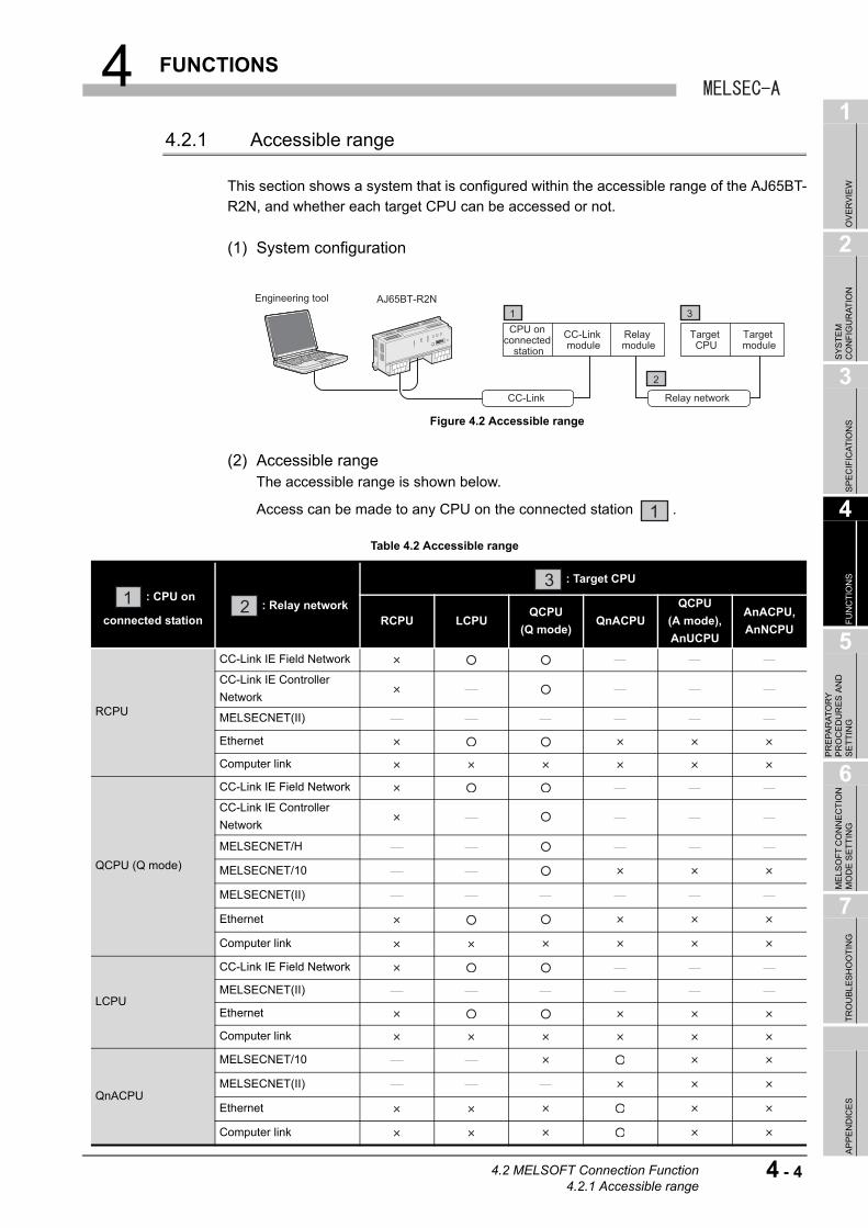
4 FUNCTIONS
1
OV
ER
VIE
W
2
SY
ST
EM
C
ON
FIG
UR
AT
ION
3
SP
EC
IFIC
AT
ION
S
4
FU
NC
TIO
NS
5
PR
EP
AR
AT
OR
Y
PR
OC
ED
UR
ES
AN
D
SE
TT
ING
6
ME
LSO
FT
CO
NN
EC
TIO
N
MO
DE
SE
TT
ING
7
TR
OU
BL
ES
HO
OT
ING
AP
PE
ND
ICE
S
4.2.1 Accessible range
This section shows a system that is configured within the accessible range of the AJ65BT-
R2N, and whether each target CPU can be accessed or not.
(1) System configuration
(2) Accessible rangeThe accessible range is shown below.
Access can be made to any CPU on the connected station .
Figure 4.2 Accessible range
Table 4.2 Accessible range
: CPU on
connected station: Relay network
: Target CPU
RCPU LCPUQCPU
(Q mode)QnACPU
QCPU
(A mode),
AnUCPU
AnACPU,
AnNCPU
RCPU
CC-Link IE Field Network
CC-Link IE Controller
Network
MELSECNET(II)
Ethernet
Computer link
QCPU (Q mode)
CC-Link IE Field Network
CC-Link IE Controller
Network
MELSECNET/H
MELSECNET/10
MELSECNET(II)
Ethernet
Computer link
LCPU
CC-Link IE Field Network
MELSECNET(II)
Ethernet
Computer link
QnACPU
MELSECNET/10
MELSECNET(II)
Ethernet
Computer link
Engineering tool AJ65BT-R2N
CC-Link
CPU on connected
stationTarget CPU
CC-Link module
Relay module
Target module
Relay network
1 3
2
1
1 2
3
4.2 MELSOFT Connection Function4.2.1 Accessible range
4 - 4
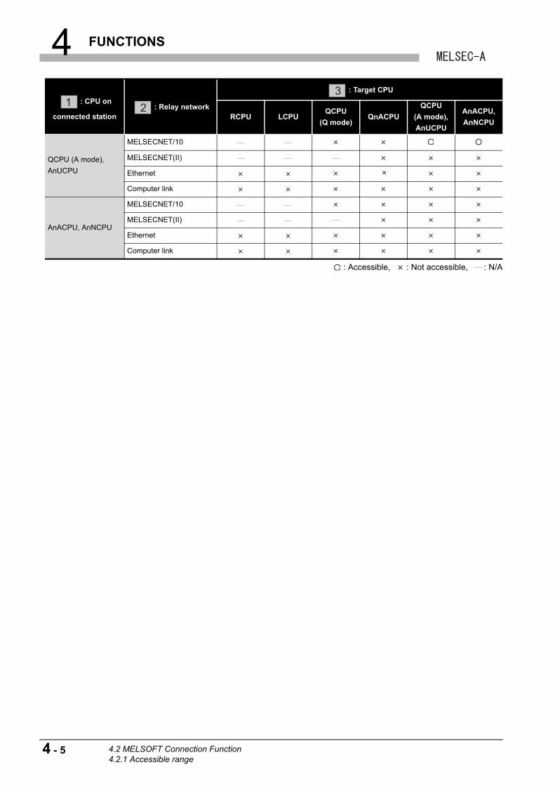
4 FUNCTIONS
: Accessible, : Not accessible, : N/A
QCPU (A mode),
AnUCPU
MELSECNET/10
MELSECNET(II)
Ethernet
Computer link
AnACPU, AnNCPU
MELSECNET/10
MELSECNET(II)
Ethernet
Computer link
: CPU on
connected station: Relay network
: Target CPU
RCPU LCPUQCPU
(Q mode)QnACPU
QCPU
(A mode),
AnUCPU
AnACPU,
AnNCPU
1 2
3
4 - 5 4.2 MELSOFT Connection Function4.2.1 Accessible range
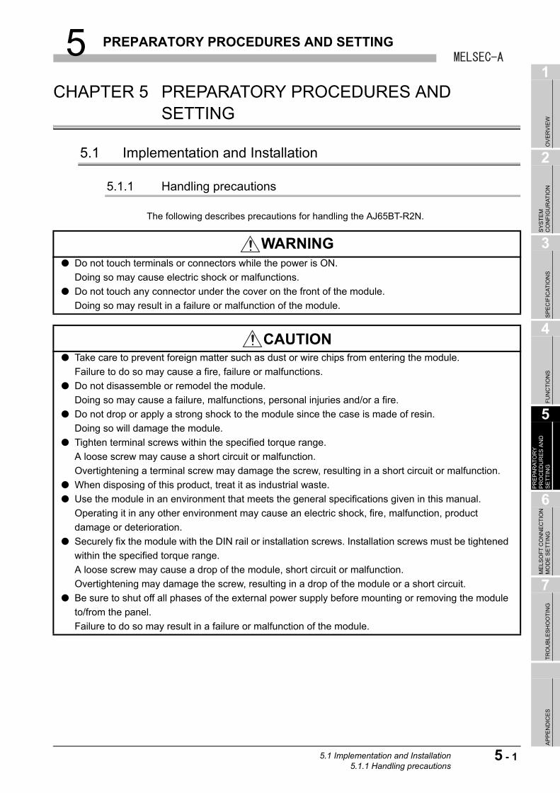
5 PREPARATORY PROCEDURES AND SETTING
1
OV
ER
VIE
W
2
SY
ST
EM
C
ON
FIG
UR
AT
ION
3
SP
EC
IFIC
AT
ION
S
4
FU
NC
TIO
NS
5
PR
EP
AR
AT
OR
Y
PR
OC
ED
UR
ES
AN
D
SE
TT
ING
6
ME
LSO
FT
CO
NN
EC
TIO
N
MO
DE
SE
TT
ING
7
TR
OU
BL
ES
HO
OT
ING
AP
PE
ND
ICE
S
CHAPTER 5 PREPARATORY PROCEDURES AND SETTING
5.1 Implementation and Installation
5.1.1 Handling precautions
The following describes precautions for handling the AJ65BT-R2N.
WARNING● Do not touch terminals or connectors while the power is ON.
Doing so may cause electric shock or malfunctions.
● Do not touch any connector under the cover on the front of the module.
Doing so may result in a failure or malfunction of the module.
CAUTION● Take care to prevent foreign matter such as dust or wire chips from entering the module.
Failure to do so may cause a fire, failure or malfunctions.
● Do not disassemble or remodel the module.
Doing so may cause a failure, malfunctions, personal injuries and/or a fire.
● Do not drop or apply a strong shock to the module since the case is made of resin.
Doing so will damage the module.
● Tighten terminal screws within the specified torque range.
A loose screw may cause a short circuit or malfunction.
Overtightening a terminal screw may damage the screw, resulting in a short circuit or malfunction.
● When disposing of this product, treat it as industrial waste.
● Use the module in an environment that meets the general specifications given in this manual.
Operating it in any other environment may cause an electric shock, fire, malfunction, product
damage or deterioration.
● Securely fix the module with the DIN rail or installation screws. Installation screws must be tightened
within the specified torque range.
A loose screw may cause a drop of the module, short circuit or malfunction.
Overtightening may damage the screw, resulting in a drop of the module or a short circuit.
● Be sure to shut off all phases of the external power supply before mounting or removing the module
to/from the panel.
Failure to do so may result in a failure or malfunction of the module.
5.1 Implementation and Installation5.1.1 Handling precautions
5 - 1
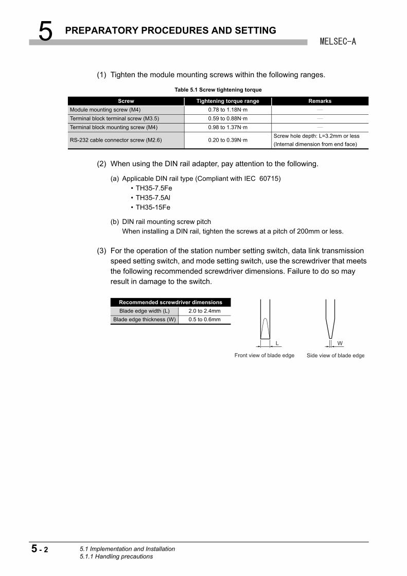
5 PREPARATORY PROCEDURES AND SETTING
(1) Tighten the module mounting screws within the following ranges.
(2) When using the DIN rail adapter, pay attention to the following.
(a) Applicable DIN rail type (Compliant with IEC 60715)
• TH35-7.5Fe
• TH35-7.5Al
• TH35-15Fe
(b) DIN rail mounting screw pitch
When installing a DIN rail, tighten the screws at a pitch of 200mm or less.
(3) For the operation of the station number setting switch, data link transmission speed setting switch, and mode setting switch, use the screwdriver that meets the following recommended screwdriver dimensions. Failure to do so may result in damage to the switch.
Table 5.1 Screw tightening torque
Screw Tightening torque range Remarks
Module mounting screw (M4) 0.78 to 1.18N·m
Terminal block terminal screw (M3.5) 0.59 to 0.88N·m
Terminal block mounting screw (M4) 0.98 to 1.37N·m
RS-232 cable connector screw (M2.6) 0.20 to 0.39N·mScrew hole depth: L=3.2mm or less
(Internal dimension from end face)
Recommended screwdriver dimensions
Blade edge width (L) 2.0 to 2.4mm
Blade edge thickness (W) 0.5 to 0.6mm
Side view of blade edgeFront view of blade edge
WL
5 - 2 5.1 Implementation and Installation5.1.1 Handling precautions
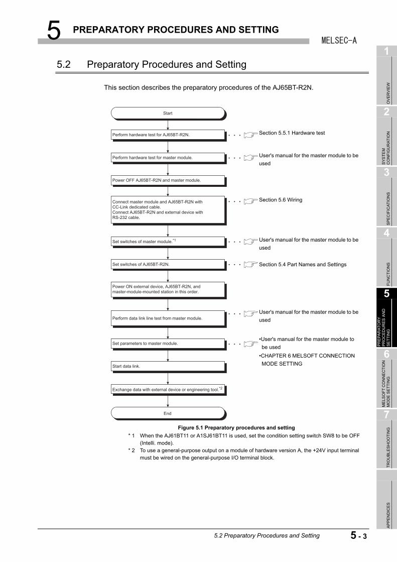
5 PREPARATORY PROCEDURES AND SETTING
1
OV
ER
VIE
W
2
SY
ST
EM
C
ON
FIG
UR
AT
ION
3
SP
EC
IFIC
AT
ION
S
4
FU
NC
TIO
NS
5
PR
EP
AR
AT
OR
Y
PR
OC
ED
UR
ES
AN
D
SE
TT
ING
6
ME
LSO
FT
CO
NN
EC
TIO
N
MO
DE
SE
TT
ING
7
TR
OU
BL
ES
HO
OT
ING
AP
PE
ND
ICE
S
5.2 Preparatory Procedures and Setting
This section describes the preparatory procedures of the AJ65BT-R2N.
* 1 When the AJ61BT11 or A1SJ61BT11 is used, set the condition setting switch SW8 to be OFF (Intelli. mode).
* 2 To use a general-purpose output on a module of hardware version A, the +24V input terminal must be wired on the general-purpose I/O terminal block.
Figure 5.1 Preparatory procedures and setting
Perform hardware test for AJ65BT-R2N.
Perform hardware test for master module.
Set switches of AJ65BT-R2N.
Set parameters to master module.
Start data link.
Exchange data with external device or engineering tool.*2
Set switches of master module.*1
Power OFF AJ65BT-R2N and master module.
Power ON external device, AJ65BT-R2N, and master-module-mounted station in this order.
Perform data link line test from master module.
Connect master module and AJ65BT-R2N with CC-Link dedicated cable. Connect AJ65BT-R2N and external device with RS-232 cable.
Start
End
Section 5.5.1 Hardware test
Section 5.6 Wiring
User's manual for the master module to be
used
User's manual for the master module to be
used
Section 5.4 Part Names and Settings
•CHAPTER 6 MELSOFT CONNECTION
MODE SETTING
User's manual for the master module to be
used
•User's manual for the master module to
be used
5.2 Preparatory Procedures and Setting
5 - 3
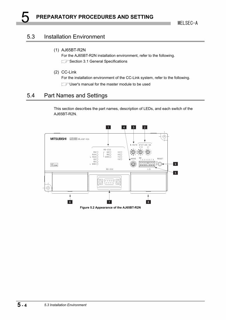
5 PREPARATORY PROCEDURES AND SETTING
5.3 Installation Environment
(1) AJ65BT-R2NFor the AJ65BT-R2N installation environment, refer to the following.
Section 3.1 General Specifications
(2) CC-LinkFor the installation environment of the CC-Link system, refer to the following.
User's manual for the master module to be used
5.4 Part Names and Settings
This section describes the part names, description of LEDs, and each switch of the
AJ65BT-R2N.
Figure 5.2 Appearance of the AJ65BT-R2N
1 4 3
9
5
876
2
5 - 4 5.3 Installation Environment
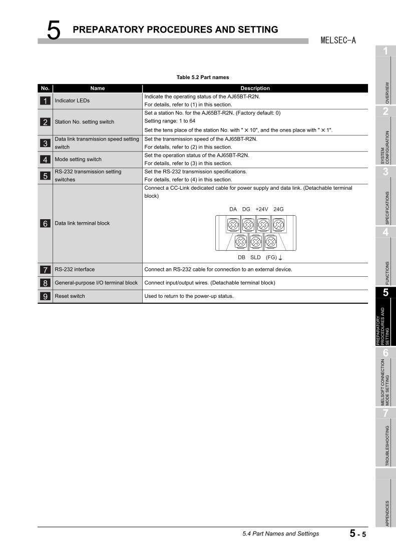
5 PREPARATORY PROCEDURES AND SETTING
1
OV
ER
VIE
W
2
SY
ST
EM
C
ON
FIG
UR
AT
ION
3
SP
EC
IFIC
AT
ION
S
4
FU
NC
TIO
NS
5
PR
EP
AR
AT
OR
Y
PR
OC
ED
UR
ES
AN
D
SE
TT
ING
6
ME
LSO
FT
CO
NN
EC
TIO
N
MO
DE
SE
TT
ING
7
TR
OU
BL
ES
HO
OT
ING
AP
PE
ND
ICE
S
Table 5.2 Part names
No. Name Description
Indicator LEDsIndicate the operating status of the AJ65BT-R2N.
For details, refer to (1) in this section.
Station No. setting switch
Set a station No. for the AJ65BT-R2N. (Factory default: 0)
Setting range: 1 to 64
Set the tens place of the station No. with " 10", and the ones place with " 1".
Data link transmission speed setting
switch
Set the transmission speed of the AJ65BT-R2N.
For details, refer to (2) in this section.
Mode setting switchSet the operation status of the AJ65BT-R2N.
For details, refer to (3) in this section.
RS-232 transmission setting
switches
Set the RS-232 transmission specifications.
For details, refer to (4) in this section.
Data link terminal block
Connect a CC-Link dedicated cable for power supply and data link. (Detachable terminal
block)
RS-232 interface Connect an RS-232 cable for connection to an external device.
General-purpose I/O terminal block Connect input/output wires. (Detachable terminal block)
Reset switch Used to return to the power-up status.
1
2
3
4
5
6
DA DG +24V
DB SLD (FG)
24G
7
8
9
5.4 Part Names and Settings
5 - 5
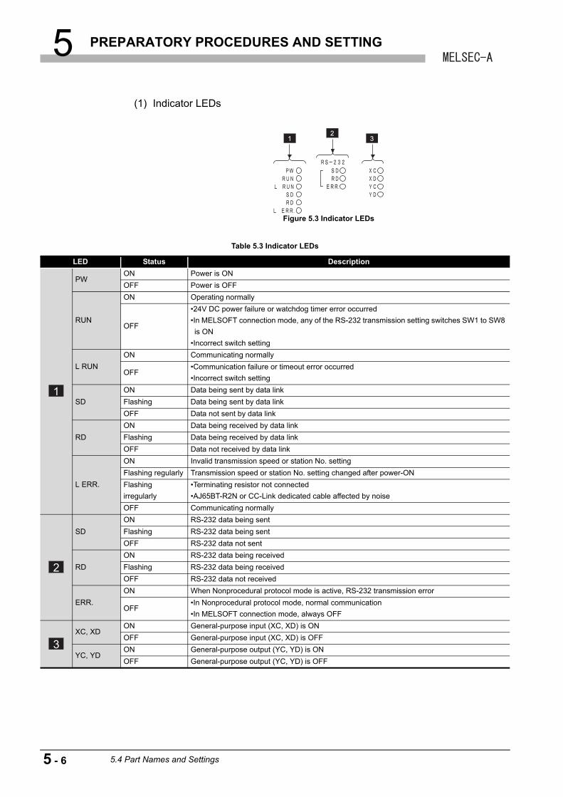
5 PREPARATORY PROCEDURES AND SETTING
(1) Indicator LEDs
Figure 5.3 Indicator LEDs
Table 5.3 Indicator LEDs
LED Status Description
PWON Power is ON
OFF Power is OFF
RUN
ON Operating normally
OFF
•24V DC power failure or watchdog timer error occurred
•In MELSOFT connection mode, any of the RS-232 transmission setting switches SW1 to SW8
is ON
•Incorrect switch setting
L RUN
ON Communicating normally
OFF•Communication failure or timeout error occurred
•Incorrect switch setting
SD
ON Data being sent by data link
Flashing Data being sent by data link
OFF Data not sent by data link
RD
ON Data being received by data link
Flashing Data being received by data link
OFF Data not received by data link
L ERR.
ON Invalid transmission speed or station No. setting
Flashing regularly Transmission speed or station No. setting changed after power-ON
Flashing
irregularly
•Terminating resistor not connected
•AJ65BT-R2N or CC-Link dedicated cable affected by noise
OFF Communicating normally
SD
ON RS-232 data being sent
Flashing RS-232 data being sent
OFF RS-232 data not sent
RD
ON RS-232 data being received
Flashing RS-232 data being received
OFF RS-232 data not received
ERR.
ON When Nonprocedural protocol mode is active, RS-232 transmission error
OFF•In Nonprocedural protocol mode, normal communication
•In MELSOFT connection mode, always OFF
XC, XDON General-purpose input (XC, XD) is ON
OFF General-purpose input (XC, XD) is OFF
YC, YDON General-purpose output (YC, YD) is ON
OFF General-purpose output (YC, YD) is OFF
12
3
1
2
3
5 - 6 5.4 Part Names and Settings
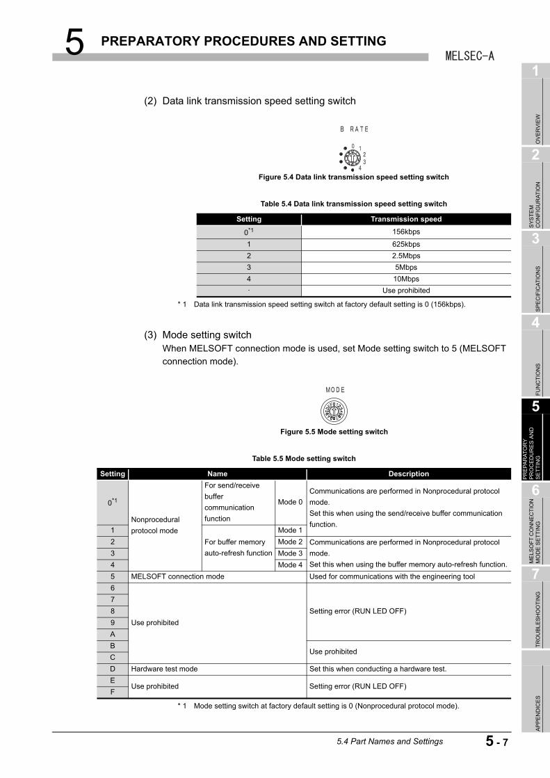
5 PREPARATORY PROCEDURES AND SETTING
1
OV
ER
VIE
W
2
SY
ST
EM
C
ON
FIG
UR
AT
ION
3
SP
EC
IFIC
AT
ION
S
4
FU
NC
TIO
NS
5
PR
EP
AR
AT
OR
Y
PR
OC
ED
UR
ES
AN
D
SE
TT
ING
6
ME
LSO
FT
CO
NN
EC
TIO
N
MO
DE
SE
TT
ING
7
TR
OU
BL
ES
HO
OT
ING
AP
PE
ND
ICE
S
(2) Data link transmission speed setting switch
* 1 Data link transmission speed setting switch at factory default setting is 0 (156kbps).
(3) Mode setting switchWhen MELSOFT connection mode is used, set Mode setting switch to 5 (MELSOFT
connection mode).
* 1 Mode setting switch at factory default setting is 0 (Nonprocedural protocol mode).
Figure 5.4 Data link transmission speed setting switch
Table 5.4 Data link transmission speed setting switch
Setting Transmission speed
0*1 156kbps
1 625kbps
2 2.5Mbps
3 5Mbps
4 10Mbps
· Use prohibited
Figure 5.5 Mode setting switch
Table 5.5 Mode setting switch
Setting Name Description
0*1
Nonprocedural
protocol mode
For send/receive
buffer
communication
function
Mode 0
Communications are performed in Nonprocedural protocol
mode.
Set this when using the send/receive buffer communication
function.1
For buffer memory
auto-refresh function
Mode 1
2 Mode 2 Communications are performed in Nonprocedural protocol
mode.
Set this when using the buffer memory auto-refresh function.
3 Mode 3
4 Mode 4
5 MELSOFT connection mode Used for communications with the engineering tool
6
Use prohibited
Setting error (RUN LED OFF)
7
8
9
A
BUse prohibited
C
D Hardware test mode Set this when conducting a hardware test.
EUse prohibited Setting error (RUN LED OFF)
F
5.4 Part Names and Settings
5 - 7
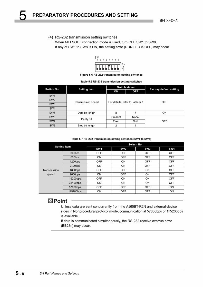
5 PREPARATORY PROCEDURES AND SETTING
(4) RS-232 transmission setting switchesWhen MELSOFT connection mode is used, turn OFF SW1 to SW8.
If any of SW1 to SW8 is ON, the setting error (RUN LED is OFF) may occur.
Unless data are sent concurrently from the AJ65BT-R2N and external-device
sides in Nonprocedural protocol mode, communication at 57600bps or 115200bps
is available.
If data is communicated simultaneously, the RS-232 receive overrun error
(BB23H) may occur.
Figure 5.6 RS-232 transmission setting switches
Table 5.6 RS-232 transmission setting switches
Switch No. Setting itemSwitch status
Factory default settingON OFF
SW1
Transmission speed For details, refer to Table 5.7 OFFSW2
SW3
SW4
SW5 Data bit length 8 7 ON
SW6Parity bit
Present None
OFFSW7 Even Odd
SW8 Stop bit length 2 1
Table 5.7 RS-232 transmission setting switches (SW1 to SW4)
Setting itemSwitch No.
SW1 SW2 SW3 SW4
Transmission
speed
300bps OFF OFF OFF OFF
600bps ON OFF OFF OFF
1200bps OFF ON OFF OFF
2400bps ON ON OFF OFF
4800bps OFF OFF ON OFF
9600bps ON OFF ON OFF
19200bps OFF ON ON OFF
38400bps ON ON ON OFF
57600bps OFF OFF OFF ON
115200bps ON OFF OFF ON
5 - 8 5.4 Part Names and Settings
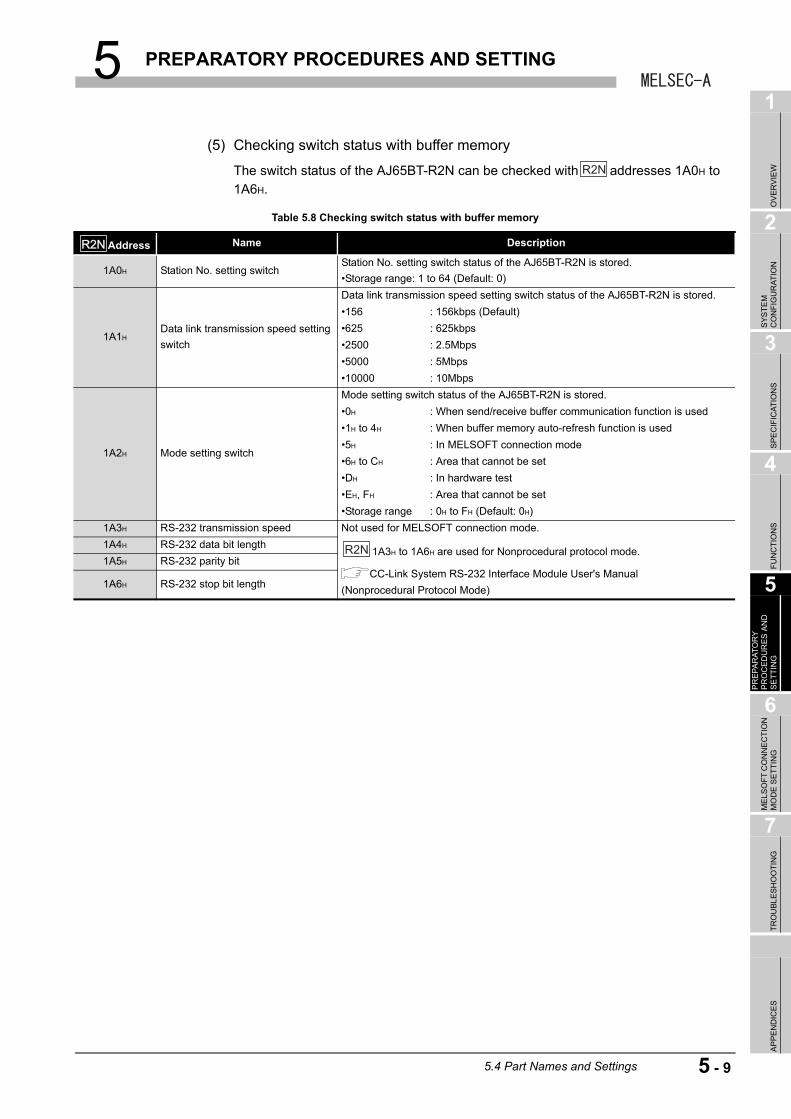
5 PREPARATORY PROCEDURES AND SETTING
1
OV
ER
VIE
W
2
SY
ST
EM
C
ON
FIG
UR
AT
ION
3
SP
EC
IFIC
AT
ION
S
4
FU
NC
TIO
NS
5
PR
EP
AR
AT
OR
Y
PR
OC
ED
UR
ES
AN
D
SE
TT
ING
6
ME
LSO
FT
CO
NN
EC
TIO
N
MO
DE
SE
TT
ING
7
TR
OU
BL
ES
HO
OT
ING
AP
PE
ND
ICE
S
(5) Checking switch status with buffer memory
The switch status of the AJ65BT-R2N can be checked with addresses 1A0H to
1A6H.
Table 5.8 Checking switch status with buffer memory
Address Name Description
1A0H Station No. setting switch Station No. setting switch status of the AJ65BT-R2N is stored.
•Storage range: 1 to 64 (Default: 0)
1A1HData link transmission speed setting
switch
Data link transmission speed setting switch status of the AJ65BT-R2N is stored.
•156 : 156kbps (Default)
•625 : 625kbps
•2500 : 2.5Mbps
•5000 : 5Mbps
•10000 : 10Mbps
1A2H Mode setting switch
Mode setting switch status of the AJ65BT-R2N is stored.
•0H : When send/receive buffer communication function is used
•1H to 4H : When buffer memory auto-refresh function is used
•5H : In MELSOFT connection mode
•6H to CH : Area that cannot be set
•DH : In hardware test
•EH, FH : Area that cannot be set
•Storage range : 0H to FH (Default: 0H)
1A3H RS-232 transmission speed Not used for MELSOFT connection mode.
1A3H to 1A6H are used for Nonprocedural protocol mode.
CC-Link System RS-232 Interface Module User's Manual
(Nonprocedural Protocol Mode)
1A4H RS-232 data bit length
1A5H RS-232 parity bit
1A6H RS-232 stop bit length
R2N
R2NR2N
R2N
5.4 Part Names and Settings
5 - 9
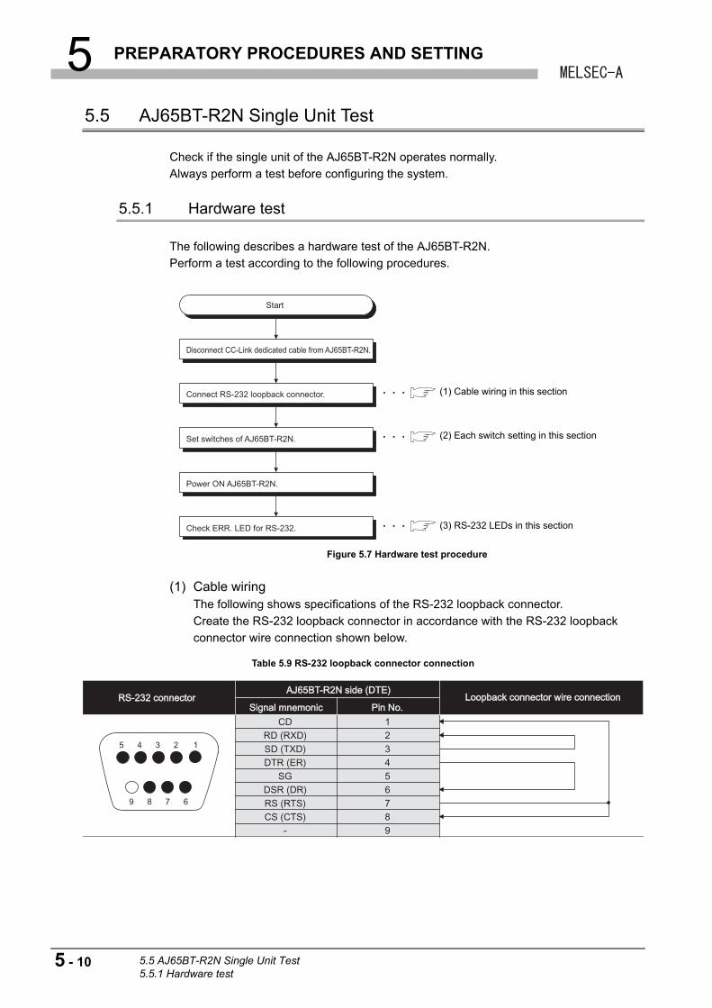
5 PREPARATORY PROCEDURES AND SETTING
5.5 AJ65BT-R2N Single Unit Test
Check if the single unit of the AJ65BT-R2N operates normally.
Always perform a test before configuring the system.
5.5.1 Hardware test
The following describes a hardware test of the AJ65BT-R2N.
Perform a test according to the following procedures.
(1) Cable wiringThe following shows specifications of the RS-232 loopback connector.
Create the RS-232 loopback connector in accordance with the RS-232 loopback
connector wire connection shown below.
Figure 5.7 Hardware test procedure
Table 5.9 RS-232 loopback connector connection
Disconnect CC-Link dedicated cable from AJ65BT-R2N.
Connect RS-232 loopback connector.
Set switches of AJ65BT-R2N.
Power ON AJ65BT-R2N.
Check ERR. LED for RS-232.
Start
(1) Cable wiring in this section
(2) Each switch setting in this section
(3) RS-232 LEDs in this section
5 4 3 2
9 8 7 6
1
RS-232 connectorRS-232 connectorAJ65BT-R2N side (DTE)AJ65BT-R2N side (DTE)
Signal mnemonicSignal mnemonic
CDRD (RXD)SD (TXD)DTR (ER)
SGDSR (DR)RS (RTS)CS (CTS)
-
123456789
Pin No.Pin No.Loopback connector wire connectionLoopback connector wire connection
5 - 10 5.5 AJ65BT-R2N Single Unit Test5.5.1 Hardware test
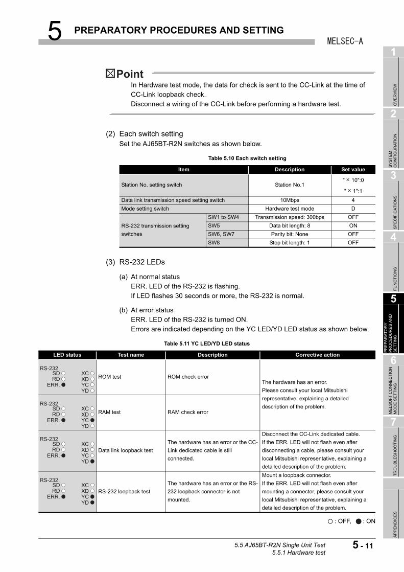
5 PREPARATORY PROCEDURES AND SETTING
1
OV
ER
VIE
W
2
SY
ST
EM
C
ON
FIG
UR
AT
ION
3
SP
EC
IFIC
AT
ION
S
4
FU
NC
TIO
NS
5
PR
EP
AR
AT
OR
Y
PR
OC
ED
UR
ES
AN
D
SE
TT
ING
6
ME
LSO
FT
CO
NN
EC
TIO
N
MO
DE
SE
TT
ING
7
TR
OU
BL
ES
HO
OT
ING
AP
PE
ND
ICE
S
In Hardware test mode, the data for check is sent to the CC-Link at the time of
CC-Link loopback check.
Disconnect a wiring of the CC-Link before performing a hardware test.
(2) Each switch settingSet the AJ65BT-R2N switches as shown below.
(3) RS-232 LEDs
(a) At normal status
ERR. LED of the RS-232 is flashing.
If LED flashes 30 seconds or more, the RS-232 is normal.
(b) At error status
ERR. LED of the RS-232 is turned ON.
Errors are indicated depending on the YC LED/YD LED status as shown below.
: OFF, : ON
Table 5.10 Each switch setting
Item Description Set value
Station No. setting switch Station No.1" 10":0
" 1":1
Data link transmission speed setting switch 10Mbps 4
Mode setting switch Hardware test mode D
RS-232 transmission setting
switches
SW1 to SW4 Transmission speed: 300bps OFF
SW5 Data bit length: 8 ON
SW6, SW7 Parity bit: None OFF
SW8 Stop bit length: 1 OFF
Table 5.11 YC LED/YD LED status
LED status Test name Description Corrective action
ROM test ROM check errorThe hardware has an error.
Please consult your local Mitsubishi
representative, explaining a detailed
description of the problem.RAM test RAM check error
Data link loopback test
The hardware has an error or the CC-
Link dedicated cable is still
connected.
Disconnect the CC-Link dedicated cable.
If the ERR. LED will not flash even after
disconnecting a cable, please consult your
local Mitsubishi representative, explaining a
detailed description of the problem.
RS-232 loopback test
The hardware has an error or the RS-
232 loopback connector is not
mounted.
Mount a loopback connector.
If the ERR. LED will not flash even after
mounting a connector, please consult your
local Mitsubishi representative, explaining a
detailed description of the problem.
5.5 AJ65BT-R2N Single Unit Test5.5.1 Hardware test
5 - 11
5 PREPARATORY PROCEDURES AND SETTING
5.6 Wiring
5.6.1 CC-Link dedicated cable connection method
The following describes the connection method of a CC-Link dedicated cable.
CAUTION● Be sure to shut off all phases of the external power supply used by the system before installation or
wiring.
Failure to do so may cause an electric shock or damage to the product.
● Attach the terminal cover to the product before energizing and operating the system after installation
or wiring.
Failure to do so may cause an electric shock.
● Be sure to shut off all phases of the external power supply used by the system before cleaning or
retightening the terminal screw.
Failure to do so may result in a failure or malfunction of the module.
A loose screw may cause a drop of the module, short circuit or malfunction.
Overtightening may damage the screw, resulting in a drop of the module, short circuit or malfunction.
● Do not install the control or communication cable(s) together with the main circuit or power cables.
Keep a distance of 100mm or more between them.
Failure to do so may cause malfunctions due to noise.
● Always ground the FG terminal to the protective ground conductor.
Failure to do so may result in electric shock or malfunctions.
● Check the rated voltage and terminal layout and then wire the module correctly.
Connecting a power supply of a different voltage rating or incorrect wiring may cause a fire or failure.
● Completely connect each cable connector to each receptacle.
Failure to do so may cause malfunctions due to poor contact.
● Place the connection wires and cables in a duct or clamp them.
If not, dangling cables may swing or inadvertently be pulled, resulting in damage to the module and/
or cables or malfunctions due to poor cable connection.
● Do not install the control cable(s) together with the communication cable(s).
Doing so may cause malfunctions due to noise.
● Always use the data link terminal block for connection of a CC-Link dedicated cable to a master
module.
Care must be taken because, if the cable is incorrectly inserted into the general-purpose I/O terminal
block instead of the data link terminal block, the module will break down.
5 - 12 5.6 Wiring5.6.1 CC-Link dedicated cable connection method
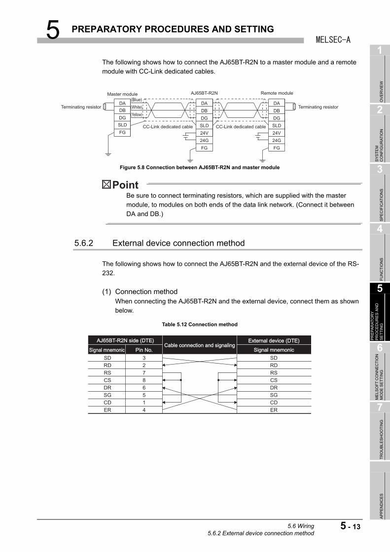
5 PREPARATORY PROCEDURES AND SETTING
1
OV
ER
VIE
W
2
SY
ST
EM
C
ON
FIG
UR
AT
ION
3
SP
EC
IFIC
AT
ION
S
4
FU
NC
TIO
NS
5
PR
EP
AR
AT
OR
Y
PR
OC
ED
UR
ES
AN
D
SE
TT
ING
6
ME
LSO
FT
CO
NN
EC
TIO
N
MO
DE
SE
TT
ING
7
TR
OU
BL
ES
HO
OT
ING
AP
PE
ND
ICE
S
The following shows how to connect the AJ65BT-R2N to a master module and a remote
module with CC-Link dedicated cables.
Be sure to connect terminating resistors, which are supplied with the master
module, to modules on both ends of the data link network. (Connect it between
DA and DB.)
5.6.2 External device connection method
The following shows how to connect the AJ65BT-R2N and the external device of the RS-
232.
(1) Connection methodWhen connecting the AJ65BT-R2N and the external device, connect them as shown
below.
Figure 5.8 Connection between AJ65BT-R2N and master module
Table 5.12 Connection method
Master module
CC-Link dedicated cable CC-Link dedicated cable
DA
DB
DG
SLD
FG
DA
DB
DG
SLD
24V
24G
FG
DA
DB
DG
SLD
24V
24G
FG
AJ65BT-R2N Remote module(Blue)
(White)
(Yellow)
Terminating resistor Terminating resistor
AJ65BT-R2N side (DTE)AJ65BT-R2N side (DTE)
Signal mnemonicSignal mnemonic Pin No.Pin No.Cable connection and signalingCable connection and signaling
External device (DTE)External device (DTE)
Signal mnemonicSignal mnemonic
SD 3RD 2RS 7CS 8DR 6SG 5CD 1ER
SDRDRSCSDRSGCDER4
5.6 Wiring5.6.2 External device connection method
5 - 13
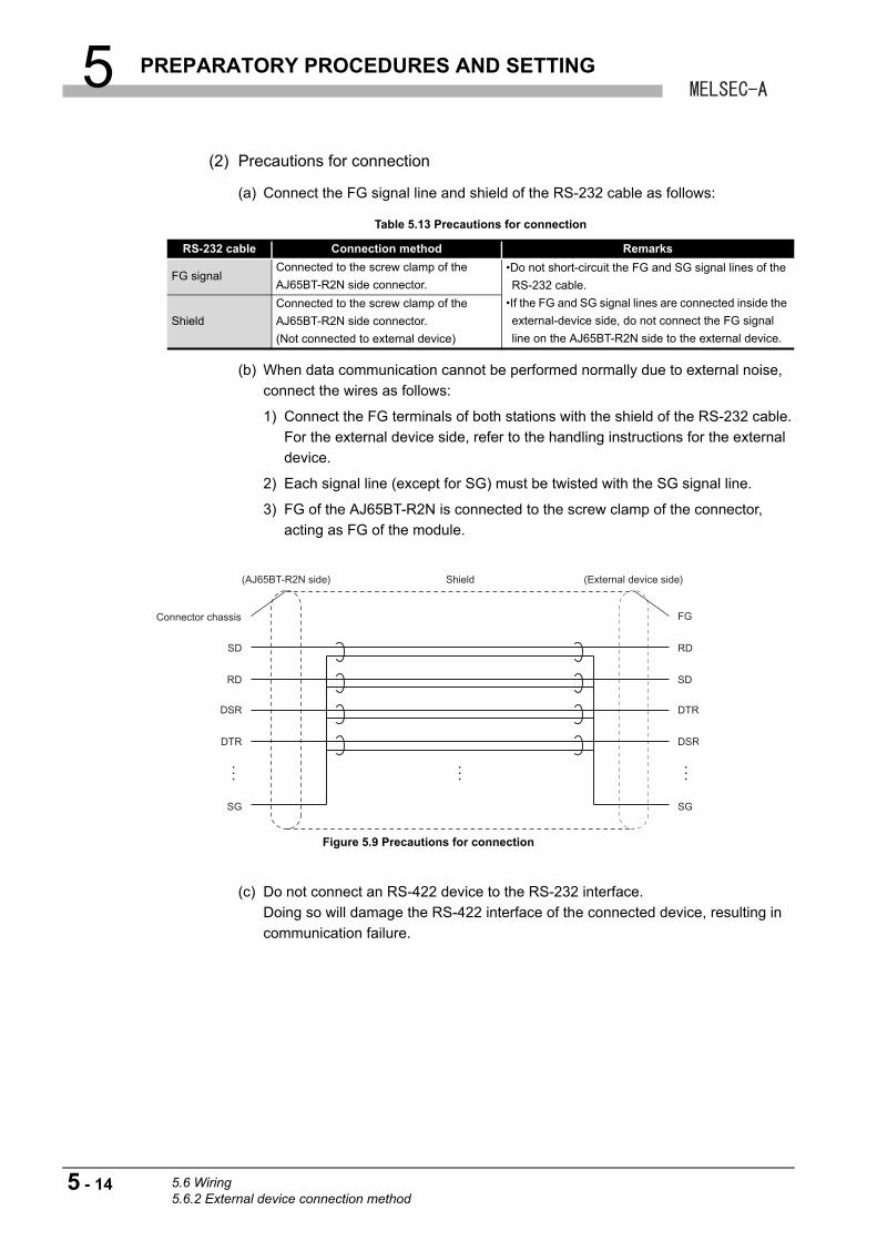
5 PREPARATORY PROCEDURES AND SETTING
(2) Precautions for connection
(a) Connect the FG signal line and shield of the RS-232 cable as follows:
(b) When data communication cannot be performed normally due to external noise,
connect the wires as follows:
1) Connect the FG terminals of both stations with the shield of the RS-232 cable.
For the external device side, refer to the handling instructions for the external
device.
2) Each signal line (except for SG) must be twisted with the SG signal line.
3) FG of the AJ65BT-R2N is connected to the screw clamp of the connector,
acting as FG of the module.
(c) Do not connect an RS-422 device to the RS-232 interface.
Doing so will damage the RS-422 interface of the connected device, resulting in
communication failure.
Table 5.13 Precautions for connection
RS-232 cable Connection method Remarks
FG signalConnected to the screw clamp of the
AJ65BT-R2N side connector.
•Do not short-circuit the FG and SG signal lines of the
RS-232 cable.
•If the FG and SG signal lines are connected inside the
external-device side, do not connect the FG signal
line on the AJ65BT-R2N side to the external device.
Shield
Connected to the screw clamp of the
AJ65BT-R2N side connector.
(Not connected to external device)
Figure 5.9 Precautions for connection
Connector chassis
(AJ65BT-R2N side)
SD
RD
DSR
DTR
SG
RD
FG
SD
DTR
DSR
SG
Shield (External device side)
5 - 14 5.6 Wiring5.6.2 External device connection method
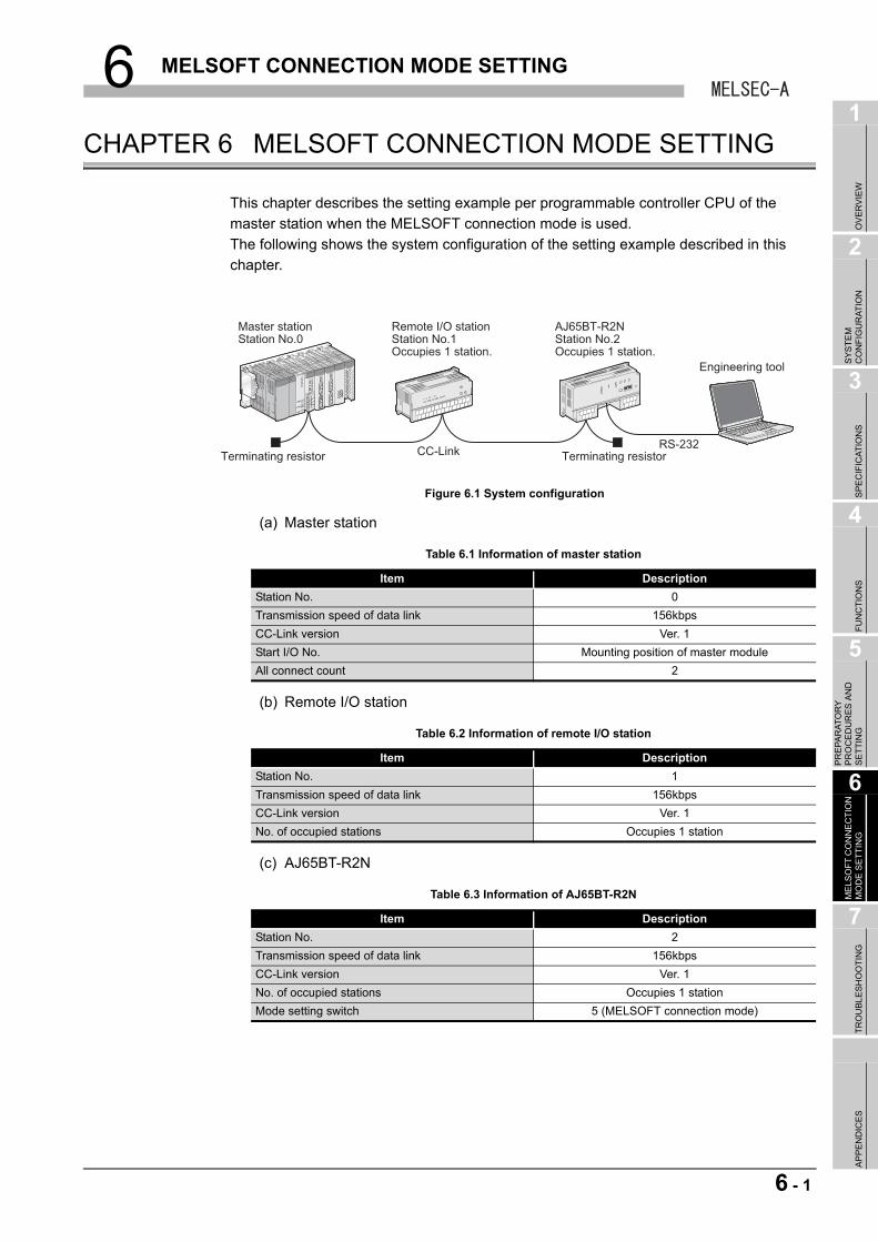
6 MELSOFT CONNECTION MODE SETTING
1
OV
ER
VIE
W
2
SY
ST
EM
C
ON
FIG
UR
AT
ION
3
SP
EC
IFIC
AT
ION
S
4
FU
NC
TIO
NS
5
PR
EP
AR
AT
OR
Y
PR
OC
ED
UR
ES
AN
D
SE
TT
ING
6
ME
LSO
FT
CO
NN
EC
TIO
N
MO
DE
SE
TT
ING
7
TR
OU
BL
ES
HO
OT
ING
AP
PE
ND
ICE
S
CHAPTER 6 MELSOFT CONNECTION MODE SETTING
This chapter describes the setting example per programmable controller CPU of the
master station when the MELSOFT connection mode is used.
The following shows the system configuration of the setting example described in this
chapter.
(a) Master station
(b) Remote I/O station
(c) AJ65BT-R2N
Figure 6.1 System configuration
Table 6.1 Information of master station
Item Description
Station No. 0
Transmission speed of data link 156kbps
CC-Link version Ver. 1
Start I/O No. Mounting position of master module
All connect count 2
Table 6.2 Information of remote I/O station
Item Description
Station No. 1
Transmission speed of data link 156kbps
CC-Link version Ver. 1
No. of occupied stations Occupies 1 station
Table 6.3 Information of AJ65BT-R2N
Item Description
Station No. 2
Transmission speed of data link 156kbps
CC-Link version Ver. 1
No. of occupied stations Occupies 1 station
Mode setting switch 5 (MELSOFT connection mode)
Master station
Terminating resistor Terminating resistorCC-Link
Remote I/O station AJ65BT-R2NStation No.0 Station No.1 Station No.2
Occupies 1 station. Occupies 1 station.
RS-232
Engineering tool
6 - 1
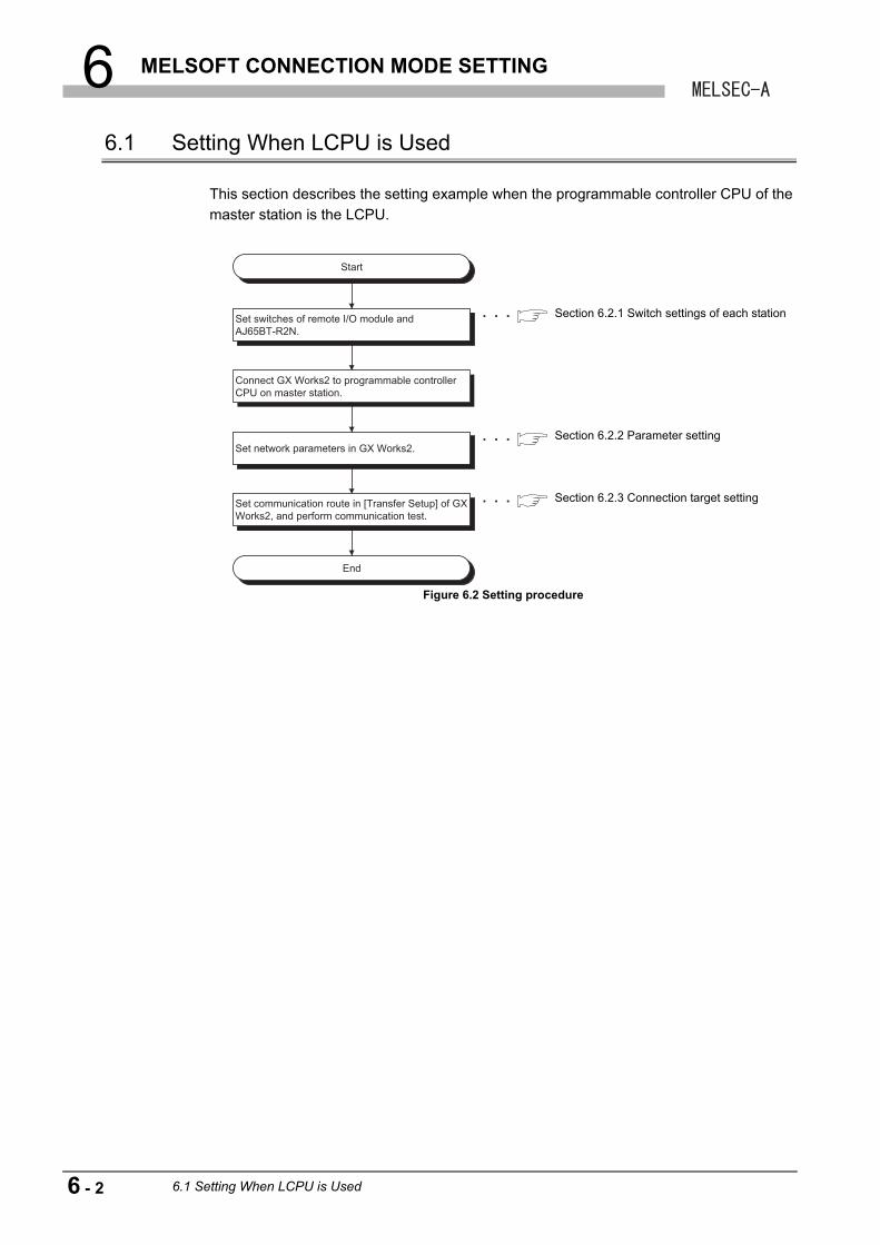
6 MELSOFT CONNECTION MODE SETTING
6.1 Setting When LCPU is Used
This section describes the setting example when the programmable controller CPU of the
master station is the LCPU.
Figure 6.2 Setting procedure
Start
End
Set switches of remote I/O module and AJ65BT-R2N.
Connect GX Works2 to programmable controller CPU on master station.
Set network parameters in GX Works2.
Set communication route in [Transfer Setup] of GX Works2, and perform communication test.
Section 6.2.1 Switch settings of each station
Section 6.2.2 Parameter setting
Section 6.2.3 Connection target setting
6 - 2 6.1 Setting When LCPU is Used
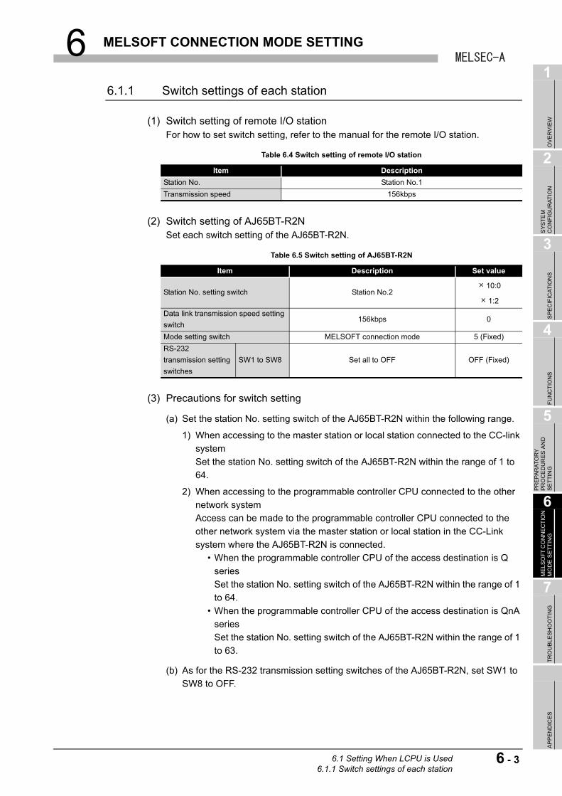
6 MELSOFT CONNECTION MODE SETTING
1
OV
ER
VIE
W
2
SY
ST
EM
C
ON
FIG
UR
AT
ION
3
SP
EC
IFIC
AT
ION
S
4
FU
NC
TIO
NS
5
PR
EP
AR
AT
OR
Y
PR
OC
ED
UR
ES
AN
D
SE
TT
ING
6
ME
LSO
FT
CO
NN
EC
TIO
N
MO
DE
SE
TT
ING
7
TR
OU
BL
ES
HO
OT
ING
AP
PE
ND
ICE
S
6.1.1 Switch settings of each station
(1) Switch setting of remote I/O stationFor how to set switch setting, refer to the manual for the remote I/O station.
(2) Switch setting of AJ65BT-R2NSet each switch setting of the AJ65BT-R2N.
(3) Precautions for switch setting
(a) Set the station No. setting switch of the AJ65BT-R2N within the following range.
1) When accessing to the master station or local station connected to the CC-link
system
Set the station No. setting switch of the AJ65BT-R2N within the range of 1 to
64.
2) When accessing to the programmable controller CPU connected to the other
network system
Access can be made to the programmable controller CPU connected to the
other network system via the master station or local station in the CC-Link
system where the AJ65BT-R2N is connected.
• When the programmable controller CPU of the access destination is Q
series
Set the station No. setting switch of the AJ65BT-R2N within the range of 1
to 64.
• When the programmable controller CPU of the access destination is QnA
series
Set the station No. setting switch of the AJ65BT-R2N within the range of 1
to 63.
(b) As for the RS-232 transmission setting switches of the AJ65BT-R2N, set SW1 to
SW8 to OFF.
Table 6.4 Switch setting of remote I/O station
Item Description
Station No. Station No.1
Transmission speed 156kbps
Table 6.5 Switch setting of AJ65BT-R2N
Item Description Set value
Station No. setting switch Station No.210:0
1:2
Data link transmission speed setting
switch156kbps 0
Mode setting switch MELSOFT connection mode 5 (Fixed)
RS-232
transmission setting
switches
SW1 to SW8 Set all to OFF OFF (Fixed)
6.1 Setting When LCPU is Used6.1.1 Switch settings of each station
6 - 3
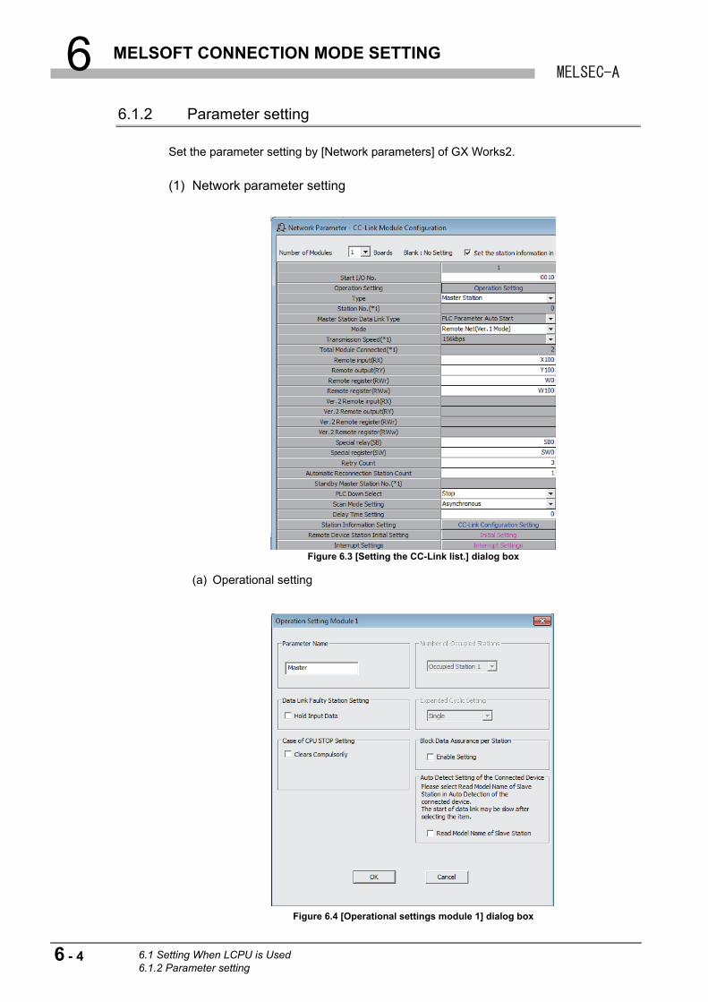
6 MELSOFT CONNECTION MODE SETTING
6.1.2 Parameter setting
Set the parameter setting by [Network parameters] of GX Works2.
(1) Network parameter setting
(a) Operational setting
Figure 6.3 [Setting the CC-Link list.] dialog box
Figure 6.4 [Operational settings module 1] dialog box
6 - 4 6.1 Setting When LCPU is Used6.1.2 Parameter setting
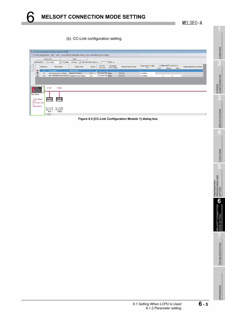
6 MELSOFT CONNECTION MODE SETTING
1
OV
ER
VIE
W
2
SY
ST
EM
C
ON
FIG
UR
AT
ION
3
SP
EC
IFIC
AT
ION
S
4
FU
NC
TIO
NS
5
PR
EP
AR
AT
OR
Y
PR
OC
ED
UR
ES
AN
D
SE
TT
ING
6
ME
LSO
FT
CO
NN
EC
TIO
N
MO
DE
SE
TT
ING
7
TR
OU
BL
ES
HO
OT
ING
AP
PE
ND
ICE
S
(b) CC-Link configuration setting
Figure 6.5 [CC-Link Configuration Module 1] dialog box
6.1 Setting When LCPU is Used6.1.2 Parameter setting
6 - 5
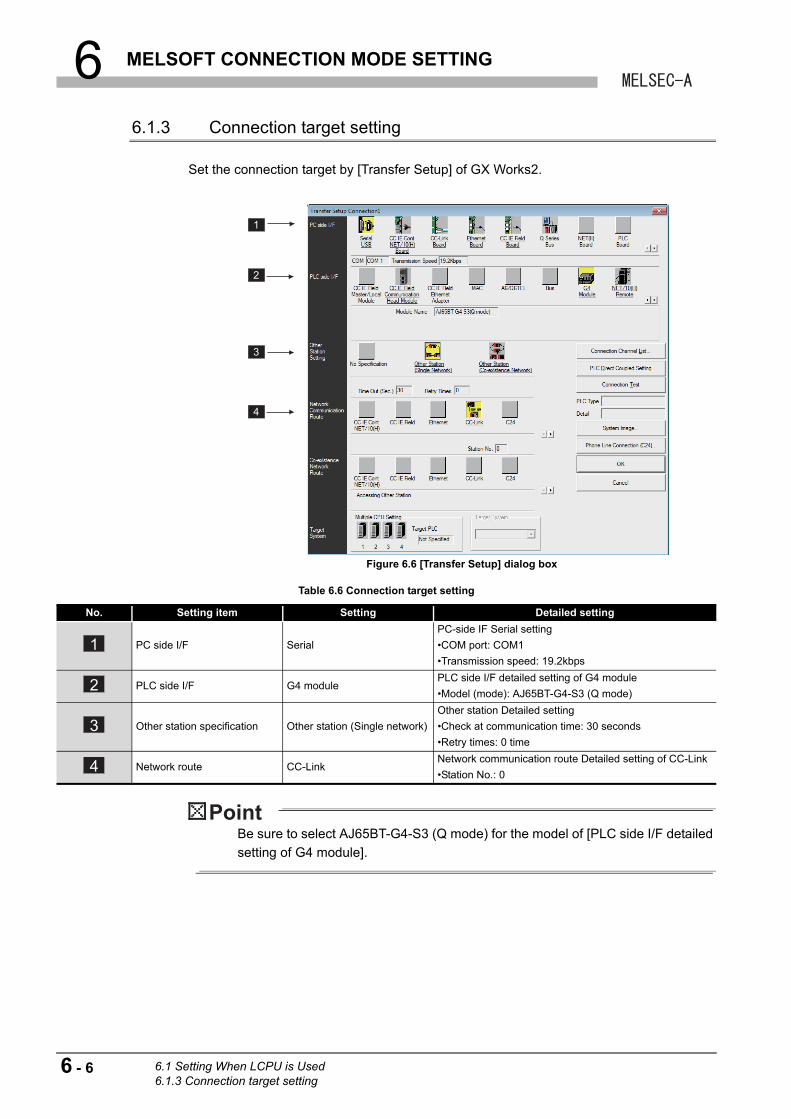
6 MELSOFT CONNECTION MODE SETTING
6.1.3 Connection target setting
Set the connection target by [Transfer Setup] of GX Works2.
Be sure to select AJ65BT-G4-S3 (Q mode) for the model of [PLC side I/F detailed
setting of G4 module].
Figure 6.6 [Transfer Setup] dialog box
Table 6.6 Connection target setting
No. Setting item Setting Detailed setting
PC side I/F Serial
PC-side IF Serial setting
•COM port: COM1
•Transmission speed: 19.2kbps
PLC side I/F G4 modulePLC side I/F detailed setting of G4 module
•Model (mode): AJ65BT-G4-S3 (Q mode)
Other station specification Other station (Single network)
Other station Detailed setting
•Check at communication time: 30 seconds
•Retry times: 0 time
Network route CC-LinkNetwork communication route Detailed setting of CC-Link
•Station No.: 0
1
2
3
4
1
2
3
4
6 - 6 6.1 Setting When LCPU is Used6.1.3 Connection target setting
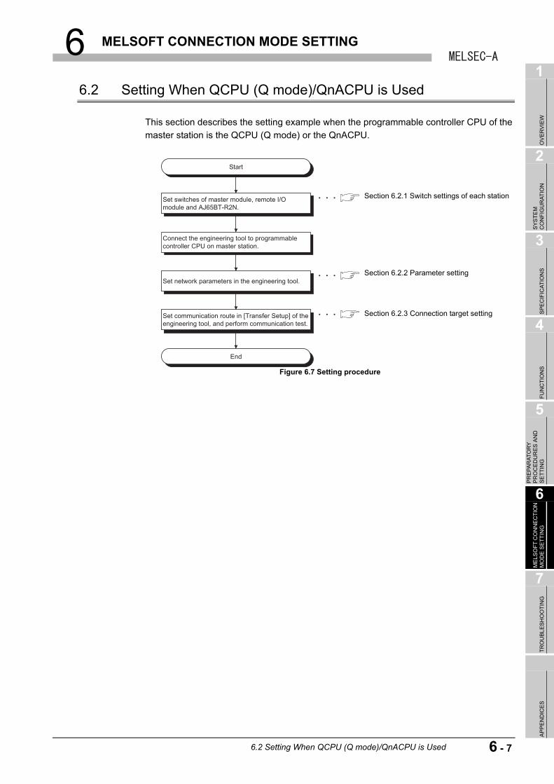
6 MELSOFT CONNECTION MODE SETTING
1
OV
ER
VIE
W
2
SY
ST
EM
C
ON
FIG
UR
AT
ION
3
SP
EC
IFIC
AT
ION
S
4
FU
NC
TIO
NS
5
PR
EP
AR
AT
OR
Y
PR
OC
ED
UR
ES
AN
D
SE
TT
ING
6
ME
LSO
FT
CO
NN
EC
TIO
N
MO
DE
SE
TT
ING
7
TR
OU
BL
ES
HO
OT
ING
AP
PE
ND
ICE
S
6.2 Setting When QCPU (Q mode)/QnACPU is Used
This section describes the setting example when the programmable controller CPU of the
master station is the QCPU (Q mode) or the QnACPU.
Figure 6.7 Setting procedure
Start
End
Set switches of master module, remote I/O module and AJ65BT-R2N.
Connect the engineering tool to programmable controller CPU on master station.
Set network parameters in the engineering tool.
Set communication route in [Transfer Setup] of the engineering tool, and perform communication test.
Section 6.2.1 Switch settings of each station
Section 6.2.2 Parameter setting
Section 6.2.3 Connection target setting
6.2 Setting When QCPU (Q mode)/QnACPU is Used
6 - 7
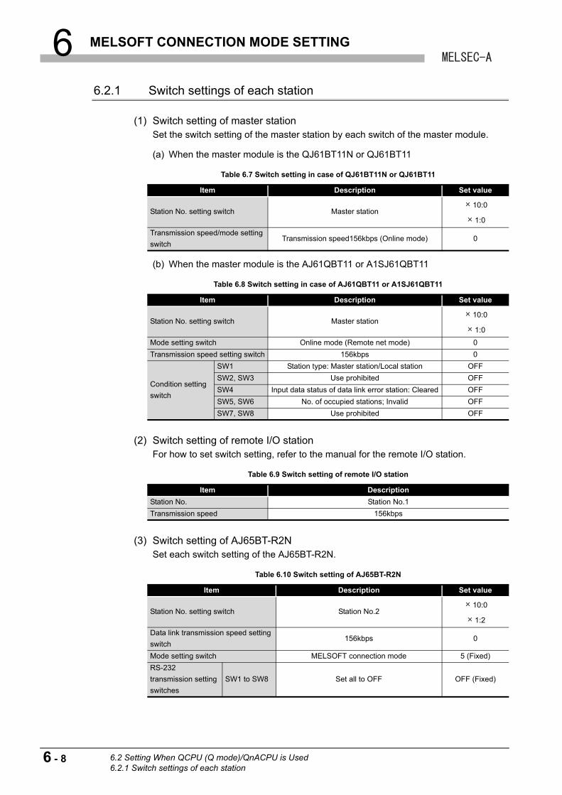
6 MELSOFT CONNECTION MODE SETTING
6.2.1 Switch settings of each station
(1) Switch setting of master stationSet the switch setting of the master station by each switch of the master module.
(a) When the master module is the QJ61BT11N or QJ61BT11
(b) When the master module is the AJ61QBT11 or A1SJ61QBT11
(2) Switch setting of remote I/O stationFor how to set switch setting, refer to the manual for the remote I/O station.
(3) Switch setting of AJ65BT-R2NSet each switch setting of the AJ65BT-R2N.
Table 6.7 Switch setting in case of QJ61BT11N or QJ61BT11
Item Description Set value
Station No. setting switch Master station10:0
1:0
Transmission speed/mode setting
switchTransmission speed156kbps (Online mode) 0
Table 6.8 Switch setting in case of AJ61QBT11 or A1SJ61QBT11
Item Description Set value
Station No. setting switch Master station10:0
1:0
Mode setting switch Online mode (Remote net mode) 0
Transmission speed setting switch 156kbps 0
Condition setting
switch
SW1 Station type: Master station/Local station OFF
SW2, SW3 Use prohibited OFF
SW4 Input data status of data link error station: Cleared OFF
SW5, SW6 No. of occupied stations; Invalid OFF
SW7, SW8 Use prohibited OFF
Table 6.9 Switch setting of remote I/O station
Item Description
Station No. Station No.1
Transmission speed 156kbps
Table 6.10 Switch setting of AJ65BT-R2N
Item Description Set value
Station No. setting switch Station No.210:0
1:2
Data link transmission speed setting
switch156kbps 0
Mode setting switch MELSOFT connection mode 5 (Fixed)
RS-232
transmission setting
switches
SW1 to SW8 Set all to OFF OFF (Fixed)
6 - 8 6.2 Setting When QCPU (Q mode)/QnACPU is Used6.2.1 Switch settings of each station
6 MELSOFT CONNECTION MODE SETTING
1
OV
ER
VIE
W
2
SY
ST
EM
C
ON
FIG
UR
AT
ION
3
SP
EC
IFIC
AT
ION
S
4
FU
NC
TIO
NS
5
PR
EP
AR
AT
OR
Y
PR
OC
ED
UR
ES
AN
D
SE
TT
ING
6
ME
LSO
FT
CO
NN
EC
TIO
N
MO
DE
SE
TT
ING
7
TR
OU
BL
ES
HO
OT
ING
AP
PE
ND
ICE
S
(4) Precautions for switch setting
(a) Set the station No. setting switch of the AJ65BT-R2N within the following range.
1) When accessing to the master station or local station connected to the CC-link
system
Set the station No. setting switch of the AJ65BT-R2N within the range of 1 to
64.
2) When accessing to the programmable controller CPU connected to the other
network system
Access can be made to the programmable controller CPU connected to the
other network system via the master station or local station in the CC-Link
system where the AJ65BT-R2N is connected.
• When access target programmable controller CPU is the Q series
Set the station No. setting switch of the AJ65BT-R2N within the range of 1
to 64.
• When access target programmable controller CPU is the QnA series
Set the station No. setting switch of the AJ65BT-R2N within the range of 1
to 63.
(b) As for the RS-232 transmission setting switches of the AJ65BT-R2N, set SW1 to
SW8 to OFF.
6.2 Setting When QCPU (Q mode)/QnACPU is Used6.2.1 Switch settings of each station
6 - 9
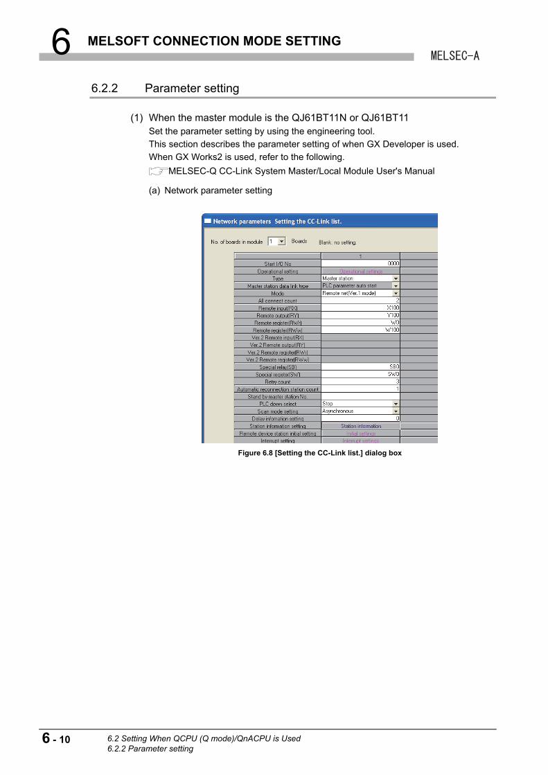
6 MELSOFT CONNECTION MODE SETTING
6.2.2 Parameter setting
(1) When the master module is the QJ61BT11N or QJ61BT11Set the parameter setting by using the engineering tool.
This section describes the parameter setting of when GX Developer is used.
When GX Works2 is used, refer to the following.
MELSEC-Q CC-Link System Master/Local Module User's Manual
(a) Network parameter setting
Figure 6.8 [Setting the CC-Link list.] dialog box
6 - 10 6.2 Setting When QCPU (Q mode)/QnACPU is Used6.2.2 Parameter setting
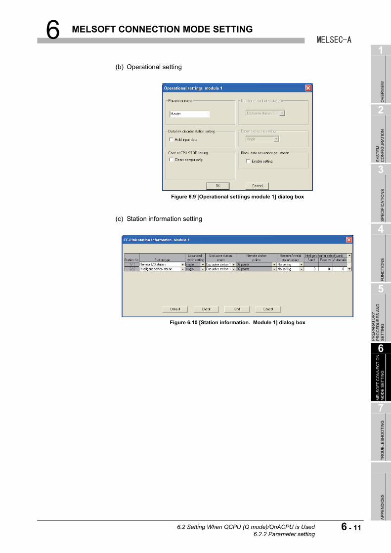
6 MELSOFT CONNECTION MODE SETTING
1
OV
ER
VIE
W
2
SY
ST
EM
C
ON
FIG
UR
AT
ION
3
SP
EC
IFIC
AT
ION
S
4
FU
NC
TIO
NS
5
PR
EP
AR
AT
OR
Y
PR
OC
ED
UR
ES
AN
D
SE
TT
ING
6
ME
LSO
FT
CO
NN
EC
TIO
N
MO
DE
SE
TT
ING
7
TR
OU
BL
ES
HO
OT
ING
AP
PE
ND
ICE
S
(b) Operational setting
(c) Station information setting
Figure 6.9 [Operational settings module 1] dialog box
Figure 6.10 [Station information. Module 1] dialog box
6.2 Setting When QCPU (Q mode)/QnACPU is Used6.2.2 Parameter setting
6 - 11
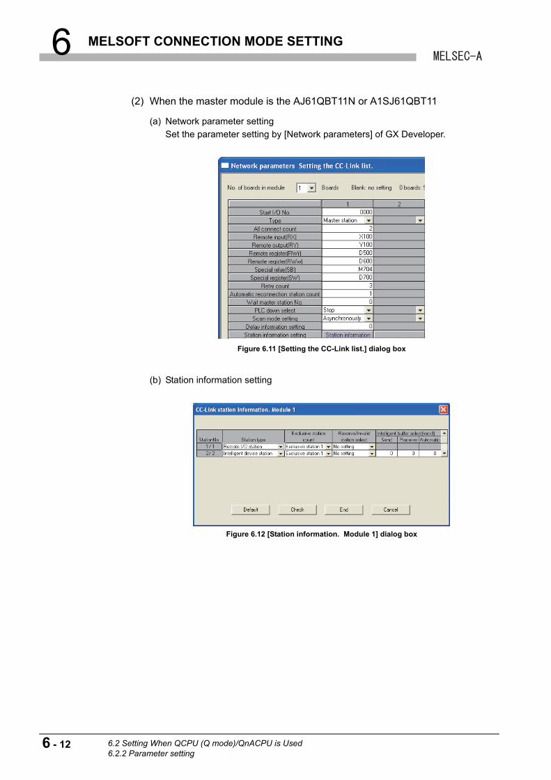
6 MELSOFT CONNECTION MODE SETTING
(2) When the master module is the AJ61QBT11N or A1SJ61QBT11
(a) Network parameter setting
Set the parameter setting by [Network parameters] of GX Developer.
(b) Station information setting
Figure 6.11 [Setting the CC-Link list.] dialog box
Figure 6.12 [Station information. Module 1] dialog box
6 - 12 6.2 Setting When QCPU (Q mode)/QnACPU is Used6.2.2 Parameter setting
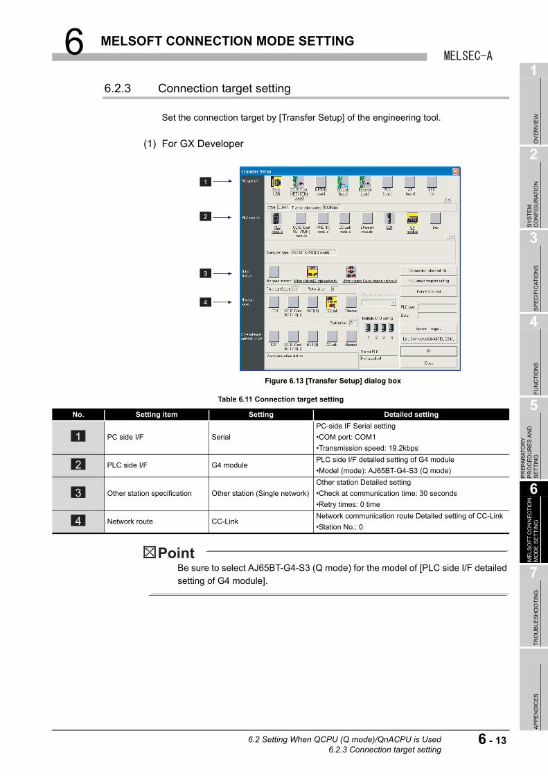
6 MELSOFT CONNECTION MODE SETTING
1
OV
ER
VIE
W
2
SY
ST
EM
C
ON
FIG
UR
AT
ION
3
SP
EC
IFIC
AT
ION
S
4
FU
NC
TIO
NS
5
PR
EP
AR
AT
OR
Y
PR
OC
ED
UR
ES
AN
D
SE
TT
ING
6
ME
LSO
FT
CO
NN
EC
TIO
N
MO
DE
SE
TT
ING
7
TR
OU
BL
ES
HO
OT
ING
AP
PE
ND
ICE
S
6.2.3 Connection target setting
Set the connection target by [Transfer Setup] of the engineering tool.
(1) For GX Developer
Be sure to select AJ65BT-G4-S3 (Q mode) for the model of [PLC side I/F detailed
setting of G4 module].
Figure 6.13 [Transfer Setup] dialog box
Table 6.11 Connection target setting
No. Setting item Setting Detailed setting
PC side I/F Serial
PC-side IF Serial setting
•COM port: COM1
•Transmission speed: 19.2kbps
PLC side I/F G4 modulePLC side I/F detailed setting of G4 module
•Model (mode): AJ65BT-G4-S3 (Q mode)
Other station specification Other station (Single network)
Other station Detailed setting
•Check at communication time: 30 seconds
•Retry times: 0 time
Network route CC-LinkNetwork communication route Detailed setting of CC-Link
•Station No.: 0
1
2
3
4
1
2
3
4
6.2 Setting When QCPU (Q mode)/QnACPU is Used6.2.3 Connection target setting
6 - 13
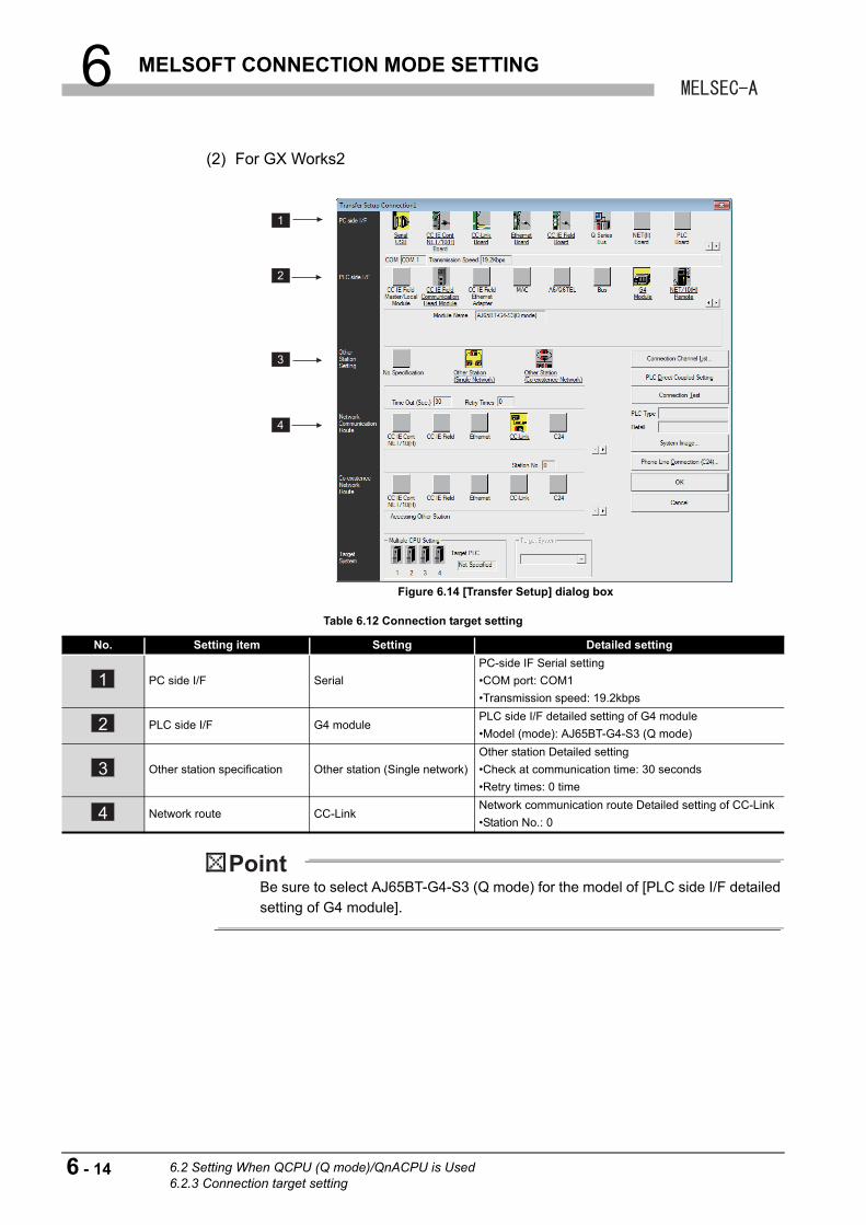
6 MELSOFT CONNECTION MODE SETTING
(2) For GX Works2
Be sure to select AJ65BT-G4-S3 (Q mode) for the model of [PLC side I/F detailed
setting of G4 module].
Figure 6.14 [Transfer Setup] dialog box
Table 6.12 Connection target setting
No. Setting item Setting Detailed setting
PC side I/F Serial
PC-side IF Serial setting
•COM port: COM1
•Transmission speed: 19.2kbps
PLC side I/F G4 modulePLC side I/F detailed setting of G4 module
•Model (mode): AJ65BT-G4-S3 (Q mode)
Other station specification Other station (Single network)
Other station Detailed setting
•Check at communication time: 30 seconds
•Retry times: 0 time
Network route CC-LinkNetwork communication route Detailed setting of CC-Link
•Station No.: 0
1
2
3
4
1
2
3
4
6 - 14 6.2 Setting When QCPU (Q mode)/QnACPU is Used6.2.3 Connection target setting

6 MELSOFT CONNECTION MODE SETTING
1
OV
ER
VIE
W
2
SY
ST
EM
C
ON
FIG
UR
AT
ION
3
SP
EC
IFIC
AT
ION
S
4
FU
NC
TIO
NS
5
PR
EP
AR
AT
OR
Y
PR
OC
ED
UR
ES
AN
D
SE
TT
ING
6
ME
LSO
FT
CO
NN
EC
TIO
N
MO
DE
SE
TT
ING
7
TR
OU
BL
ES
HO
OT
ING
AP
PE
ND
ICE
S
6.3 Setting When ACPU/QCPU (A mode) is Used
This section describes the setting example when the programmable controller CPU of the
master station is the ACPU or QCPU (A mode).
Figure 6.15 Setting procedure
Start
End
Set switches of master module, remote I/O module and AJ65BT-R2N.
Connect GX Developer to programmable controller CPU on master station.
Set parameters.
Set communication route in [Transfer Setup] of GX Developer, and perform communication test.
Section 6.3.1 Switch settings of each station
Section 6.3.2 Parameter setting
Section 6.3.3 Connection target setting
6.3 Setting When ACPU/QCPU (A mode) is Used
6 - 15
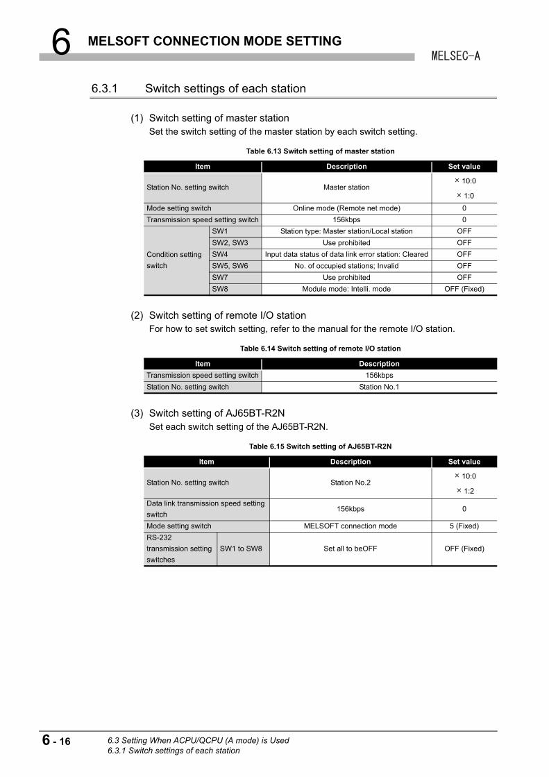
6 MELSOFT CONNECTION MODE SETTING
6.3.1 Switch settings of each station
(1) Switch setting of master stationSet the switch setting of the master station by each switch setting.
(2) Switch setting of remote I/O stationFor how to set switch setting, refer to the manual for the remote I/O station.
(3) Switch setting of AJ65BT-R2NSet each switch setting of the AJ65BT-R2N.
Table 6.13 Switch setting of master station
Item Description Set value
Station No. setting switch Master station10:0
1:0
Mode setting switch Online mode (Remote net mode) 0
Transmission speed setting switch 156kbps 0
Condition setting
switch
SW1 Station type: Master station/Local station OFF
SW2, SW3 Use prohibited OFF
SW4 Input data status of data link error station: Cleared OFF
SW5, SW6 No. of occupied stations; Invalid OFF
SW7 Use prohibited OFF
SW8 Module mode: Intelli. mode OFF (Fixed)
Table 6.14 Switch setting of remote I/O station
Item Description
Transmission speed setting switch 156kbps
Station No. setting switch Station No.1
Table 6.15 Switch setting of AJ65BT-R2N
Item Description Set value
Station No. setting switch Station No.210:0
1:2
Data link transmission speed setting
switch156kbps 0
Mode setting switch MELSOFT connection mode 5 (Fixed)
RS-232
transmission setting
switches
SW1 to SW8 Set all to beOFF OFF (Fixed)
6 - 16 6.3 Setting When ACPU/QCPU (A mode) is Used6.3.1 Switch settings of each station
6 MELSOFT CONNECTION MODE SETTING
1
OV
ER
VIE
W
2
SY
ST
EM
C
ON
FIG
UR
AT
ION
3
SP
EC
IFIC
AT
ION
S
4
FU
NC
TIO
NS
5
PR
EP
AR
AT
OR
Y
PR
OC
ED
UR
ES
AN
D
SE
TT
ING
6
ME
LSO
FT
CO
NN
EC
TIO
N
MO
DE
SE
TT
ING
7
TR
OU
BL
ES
HO
OT
ING
AP
PE
ND
ICE
S
(4) Precautions for switch setting
(a) Set the station No. of the AJ65BT-R2N within the following range.
1) When accessing to the master station or local station connected to the CC-link
system
Set the station No. setting switch of the AJ65BT-R2N within the range of 1 to
64.
2) When accessing to the programmable controller CPU connected to the other
network system
When accessing to the A series programmable controller CPU via the master
station or local station in the CC-Link system connected to the AJ65BT-R2N,
set the station No. setting switch of the AJ65BT-R2N within the range of 1 to
63.
(b) Set the condition setting switch SW8 of the master station or local station to OFF
(Intelli. mode).
(c) As for the RS-232 transmission setting switches of the AJ65BT-R2N, set SW1 to
SW8 to OFF.
6.3 Setting When ACPU/QCPU (A mode) is Used6.3.1 Switch settings of each station
6 - 17
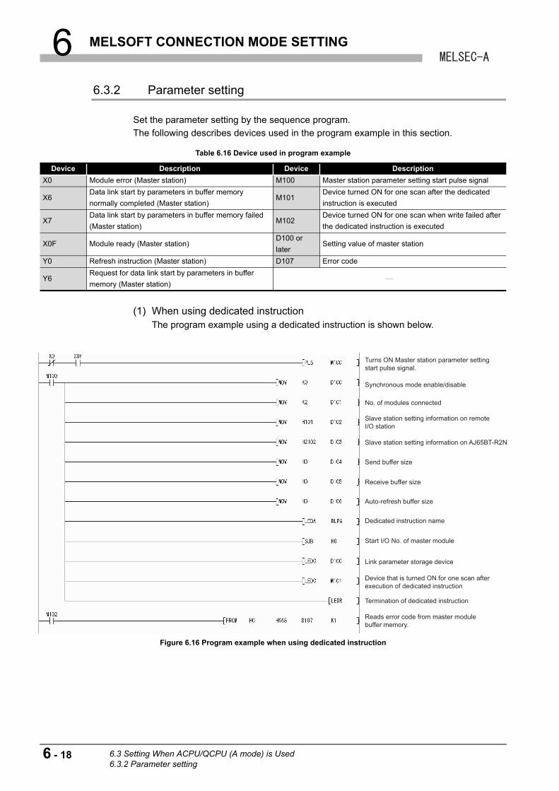
6 MELSOFT CONNECTION MODE SETTING
6.3.2 Parameter setting
Set the parameter setting by the sequence program.
The following describes devices used in the program example in this section.
(1) When using dedicated instructionThe program example using a dedicated instruction is shown below.
Table 6.16 Device used in program example
Device Description Device Description
X0 Module error (Master station) M100 Master station parameter setting start pulse signal
X6Data link start by parameters in buffer memory
normally completed (Master station)M101
Device turned ON for one scan after the dedicated
instruction is executed
X7Data link start by parameters in buffer memory failed
(Master station)M102
Device turned ON for one scan when write failed after
the dedicated instruction is executed
X0F Module ready (Master station)D100 or
laterSetting value of master station
Y0 Refresh instruction (Master station) D107 Error code
Y6Request for data link start by parameters in buffer
memory (Master station)
Figure 6.16 Program example when using dedicated instruction
Turns ON Master station parameter setting start pulse signal.
Synchronous mode enable/disable
No. of modules connected
Slave station setting information on remote I/O station
Slave station setting information on AJ65BT-R2N
Send buffer size
Receive buffer size
Auto-refresh buffer size
Dedicated instruction name
Termination of dedicated instruction
Reads error code from master module buffer memory.
Start I/O No. of master module
Link parameter storage device
Device that is turned ON for one scan after execution of dedicated instruction
6 - 18 6.3 Setting When ACPU/QCPU (A mode) is Used6.3.2 Parameter setting
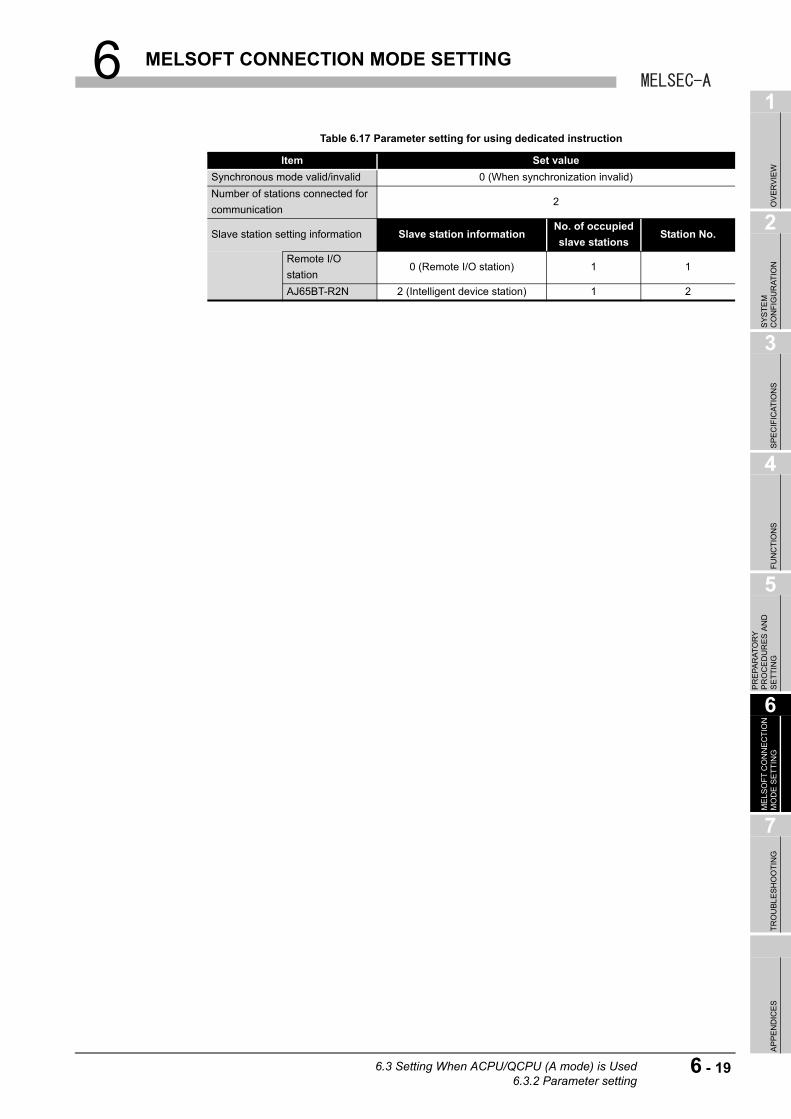
6 MELSOFT CONNECTION MODE SETTING
1
OV
ER
VIE
W
2
SY
ST
EM
C
ON
FIG
UR
AT
ION
3
SP
EC
IFIC
AT
ION
S
4
FU
NC
TIO
NS
5
PR
EP
AR
AT
OR
Y
PR
OC
ED
UR
ES
AN
D
SE
TT
ING
6
ME
LSO
FT
CO
NN
EC
TIO
N
MO
DE
SE
TT
ING
7
TR
OU
BL
ES
HO
OT
ING
AP
PE
ND
ICE
S
Table 6.17 Parameter setting for using dedicated instruction
Item Set value
Synchronous mode valid/invalid 0 (When synchronization invalid)
Number of stations connected for
communication2
Slave station setting information Slave station informationNo. of occupied
slave stationsStation No.
Remote I/O
station0 (Remote I/O station) 1 1
AJ65BT-R2N 2 (Intelligent device station) 1 2
6.3 Setting When ACPU/QCPU (A mode) is Used6.3.2 Parameter setting
6 - 19

6 MELSOFT CONNECTION MODE SETTING
(2) When using FROM/TO instructionThe program example using the FROM/TO instruction is shown below.
Figure 6.17 Program example when using FROM/TO instruction
Table 6.18 Parameter setting for using FROM/TO instruction
Item Set value
Number of stations connected for
communication2
Slave station setting information Slave station informationNo. of occupied
slave stationsStation No.
Remote I/O
station0 (Remote I/O station) 1 1
AJ65BT-R2N 2 (Intelligent device station) 1 2
Turns ON Master station parameter setting start pulse signal.
Writes to master module buffer memory.
No. of modules connected
Remote I/O station information
AJ65BT-R2N station information
Writes to master module buffer memory.
Send buffer size
Receive buffer size
Auto-refresh buffer size
Writes to master module buffer memory.
Turns ON Refresh instruction.
Turns ON Request for data link start by parameters in buffer memory.
Resets Request for data link start by parameters in buffer memory.
Reads error code from master module buffer memory.
Resets data link start by parameters in buffer memory.
6 - 20 6.3 Setting When ACPU/QCPU (A mode) is Used6.3.2 Parameter setting
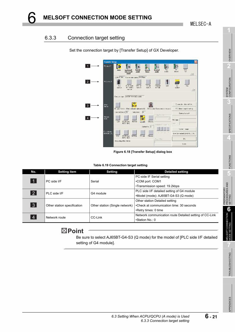
6 MELSOFT CONNECTION MODE SETTING
1
OV
ER
VIE
W
2
SY
ST
EM
C
ON
FIG
UR
AT
ION
3
SP
EC
IFIC
AT
ION
S
4
FU
NC
TIO
NS
5
PR
EP
AR
AT
OR
Y
PR
OC
ED
UR
ES
AN
D
SE
TT
ING
6
ME
LSO
FT
CO
NN
EC
TIO
N
MO
DE
SE
TT
ING
7
TR
OU
BL
ES
HO
OT
ING
AP
PE
ND
ICE
S
6.3.3 Connection target setting
Set the connection target by [Transfer Setup] of GX Developer.
Be sure to select AJ65BT-G4-S3 (Q mode) for the model of [PLC side I/F detailed
setting of G4 module].
Figure 6.18 [Transfer Setup] dialog box
Table 6.19 Connection target setting
No. Setting item Setting Detailed setting
PC side I/F Serial
PC-side IF Serial setting
•COM port: COM1
•Transmission speed: 19.2kbps
PLC side I/F G4 modulePLC side I/F detailed setting of G4 module
•Model (mode): AJ65BT-G4-S3 (Q mode)
Other station specification Other station (Single network)
Other station Detailed setting
•Check at communication time: 30 seconds
•Retry times: 0 time
Network route CC-LinkNetwork communication route Detailed setting of CC-Link
•Station No.: 0
1
2
3
4
1
2
3
4
6.3 Setting When ACPU/QCPU (A mode) is Used6.3.3 Connection target setting
6 - 21

7 TROUBLESHOOTING
CHAPTER 7 TROUBLESHOOTING
This chapter describes the troubleshooting procedures and error codes of the AJ65BT-
R2N.
For troubleshooting and error codes, check the modules in the following order.
(1) Programmable controller CPU usedFor troubleshooting and error codes, refer to the following.
User's manual for the programmable controller CPU used
(2) Master module usedFor troubleshooting and error codes, refer to the following.
User's manual for the master module used
(3) AJ65BT-R2NFor troubleshooting and error codes, refer to the following.
Section 7.1 Troubleshooting When Using the MELSOFT Connection Function
Section 7.2 Error Code List
7 - 1
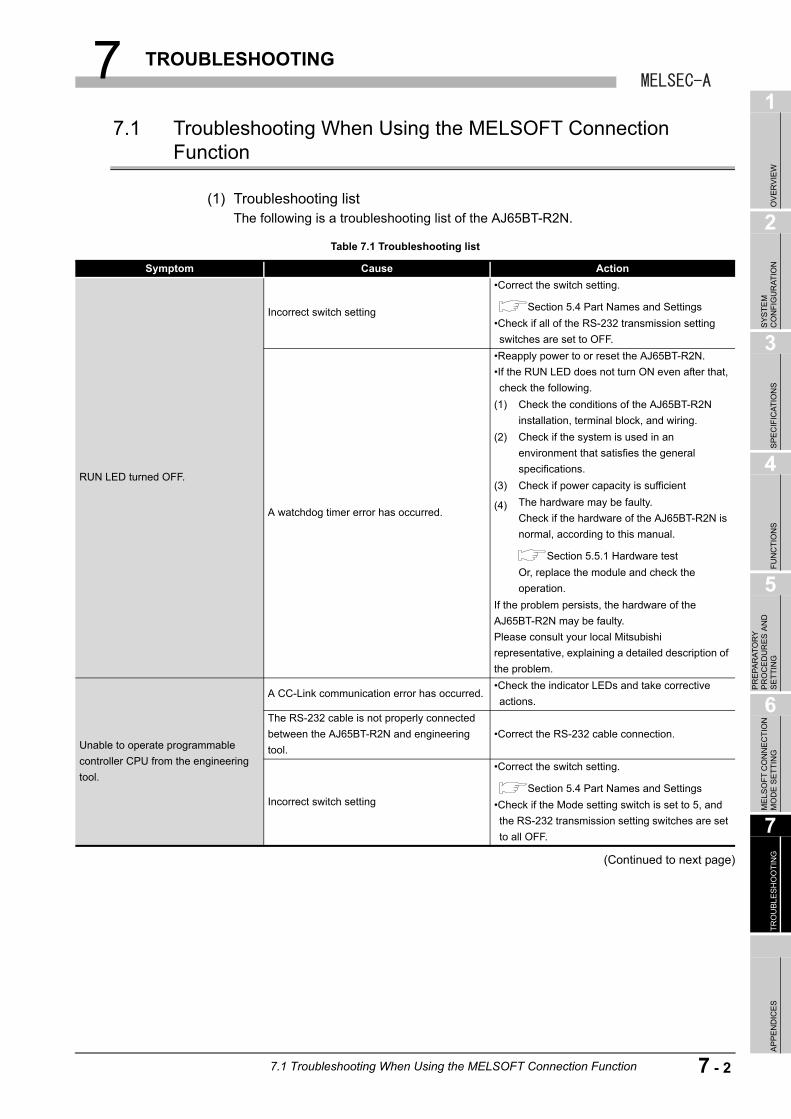
7 TROUBLESHOOTING
1
OV
ER
VIE
W
2
SY
ST
EM
C
ON
FIG
UR
AT
ION
3
SP
EC
IFIC
AT
ION
S
4
FU
NC
TIO
NS
5
PR
EP
AR
AT
OR
Y
PR
OC
ED
UR
ES
AN
D
SE
TT
ING
6
ME
LSO
FT
CO
NN
EC
TIO
N
MO
DE
SE
TT
ING
7
TR
OU
BL
ES
HO
OT
ING
AP
PE
ND
ICE
S
7.1 Troubleshooting When Using the MELSOFT Connection Function
(1) Troubleshooting listThe following is a troubleshooting list of the AJ65BT-R2N.
(Continued to next page)
Table 7.1 Troubleshooting list
Symptom Cause Action
RUN LED turned OFF.
Incorrect switch setting
•Correct the switch setting.
Section 5.4 Part Names and Settings
•Check if all of the RS-232 transmission setting
switches are set to OFF.
A watchdog timer error has occurred.
•Reapply power to or reset the AJ65BT-R2N.
•If the RUN LED does not turn ON even after that,
check the following.
(1) Check the conditions of the AJ65BT-R2N
installation, terminal block, and wiring.
(2) Check if the system is used in an
environment that satisfies the general
specifications.
(3) Check if power capacity is sufficient
(4) The hardware may be faulty.
Check if the hardware of the AJ65BT-R2N is
normal, according to this manual.
Section 5.5.1 Hardware test
Or, replace the module and check the
operation.
If the problem persists, the hardware of the
AJ65BT-R2N may be faulty.
Please consult your local Mitsubishi
representative, explaining a detailed description of
the problem.
Unable to operate programmable
controller CPU from the engineering
tool.
A CC-Link communication error has occurred.•Check the indicator LEDs and take corrective
actions.
The RS-232 cable is not properly connected
between the AJ65BT-R2N and engineering
tool.
•Correct the RS-232 cable connection.
Incorrect switch setting
•Correct the switch setting.
Section 5.4 Part Names and Settings
•Check if the Mode setting switch is set to 5, and
the RS-232 transmission setting switches are set
to all OFF.
7.1 Troubleshooting When Using the MELSOFT Connection Function
7 - 2
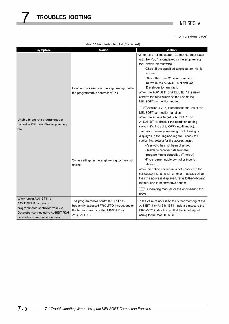
7 TROUBLESHOOTING
(From previous page)
Table 7.1Troubleshooting list (Continued)
Symptom Cause Action
Unable to operate programmable
controller CPU from the engineering
tool.
Unable to access from the engineering tool to
the programmable controller CPU.
•When an error message, "Cannot communicate
with the PLC." is displayed in the engineering
tool, check the following.
•Check if the specified target station No. is
correct.
•Check the RS-232 cable connected
between the AJ65BT-R2N and GX
Developer for any fault.
•When the AJ61BT11 or A1SJ61BT11 is used,
confirm the restrictions on the use of the
MELSOFT connection mode.
Section 4.2 (3) Precautions for use of the
MELSOFT connection function
•When the access target is AJ61BT11 or
A1SJ61BT11, check if the condition setting
switch, SW8 is set to OFF (Intelli. mode).
Some settings in the engineering tool are not
correct.
•If an error message meaning the following is
displayed in the engineering tool, check the
station No. setting for the access target.
•Password has not been changed.
•Unable to receive data from the
programmable controller. (Timeout)
•The programmable controller type is
different.
•When an online operation is not possible in the
correct setting, or when an error message other
than the above is displayed, refer to the following
manual and take corrective actions.
Operating manual for the engineering tool
used
When using AJ61BT11 or
A1SJ61BT11, access to
programmable controller from GX
Developer connected to AJ65BT-R2N
generates communication error.
The programmable controller CPU has
frequently executed FROM/TO instructions to
the buffer memory of the AJ61BT11 or
A1SJ61BT11.
•In the case of access to the buffer memory of the
AJ61BT11 or A1SJ61BT11, add a contact to the
FROM/TO instruction so that the input signal
(XnC) to the module is OFF.
7 - 3 7.1 Troubleshooting When Using the MELSOFT Connection Function
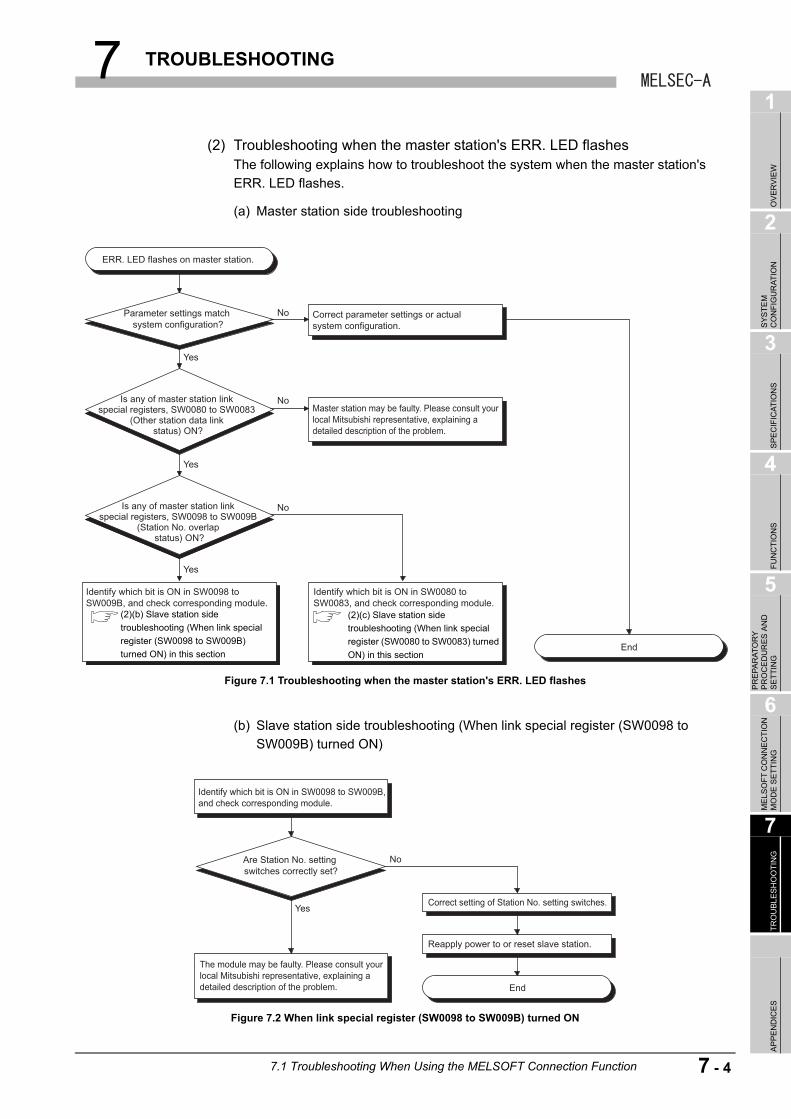
7 TROUBLESHOOTING
1
OV
ER
VIE
W
2
SY
ST
EM
C
ON
FIG
UR
AT
ION
3
SP
EC
IFIC
AT
ION
S
4
FU
NC
TIO
NS
5
PR
EP
AR
AT
OR
Y
PR
OC
ED
UR
ES
AN
D
SE
TT
ING
6
ME
LSO
FT
CO
NN
EC
TIO
N
MO
DE
SE
TT
ING
7
TR
OU
BL
ES
HO
OT
ING
AP
PE
ND
ICE
S
(2) Troubleshooting when the master station's ERR. LED flashesThe following explains how to troubleshoot the system when the master station's
ERR. LED flashes.
(a) Master station side troubleshooting
(b) Slave station side troubleshooting (When link special register (SW0098 to
SW009B) turned ON)
Figure 7.1 Troubleshooting when the master station's ERR. LED flashes
Figure 7.2 When link special register (SW0098 to SW009B) turned ON
ERR. LED flashes on master station.
No
Yes
Yes
Yes
No
No
Parameter settings match system configuration?
Is any of master station link special registers, SW0080 to SW0083
(Other station data link status) ON?
Is any of master station link special registers, SW0098 to SW009B
(Station No. overlap status) ON?
Correct parameter settings or actual system configuration.
Master station may be faulty. Please consult your local Mitsubishi representative, explaining a detailed description of the problem.
Identify which bit is ON in SW0098 to SW009B, and check corresponding module.
Identify which bit is ON in SW0080 to SW0083, and check corresponding module.
End
(2)(b) Slave station side
troubleshooting (When link special
register (SW0098 to SW009B)
turned ON) in this section
(2)(c) Slave station side
troubleshooting (When link special
register (SW0080 to SW0083) turned
ON) in this section
Identify which bit is ON in SW0098 to SW009B, and check corresponding module.
Correct setting of Station No. setting switches.
Reapply power to or reset slave station.
The module may be faulty. Please consult your local Mitsubishi representative, explaining a detailed description of the problem.
Are Station No. setting switches correctly set?
Yes
No
End
7.1 Troubleshooting When Using the MELSOFT Connection Function
7 - 4
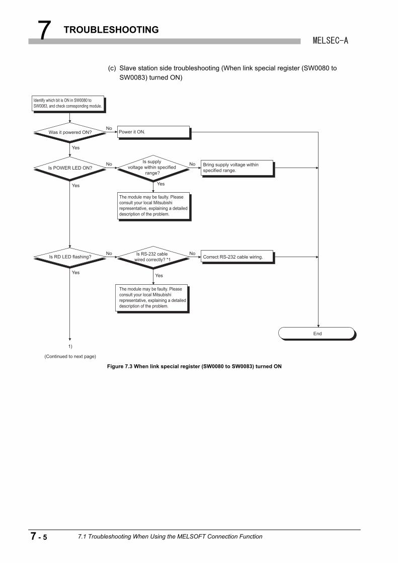
7 TROUBLESHOOTING
(c) Slave station side troubleshooting (When link special register (SW0080 to
SW0083) turned ON)
Figure 7.3 When link special register (SW0080 to SW0083) turned ON
Identify which bit is ON in SW0080 to SW0083, and check corresponding module.
The module may be faulty. Please consult your local Mitsubishi representative, explaining a detailed description of the problem.
The module may be faulty. Please consult your local Mitsubishi representative, explaining a detailed description of the problem.
Was it powered ON?
Is POWER LED ON?
Is RS-232 cable wired correctly? *1
Is RD LED flashing?
No
No
Yes
Yes
YesYes
Yes
No
No
No
Power it ON.
Bring supply voltage within specified range.
Correct RS-232 cable wiring.
End
1)
(Continued to next page)
Is supply voltage within specified
range?
7 - 5 7.1 Troubleshooting When Using the MELSOFT Connection Function
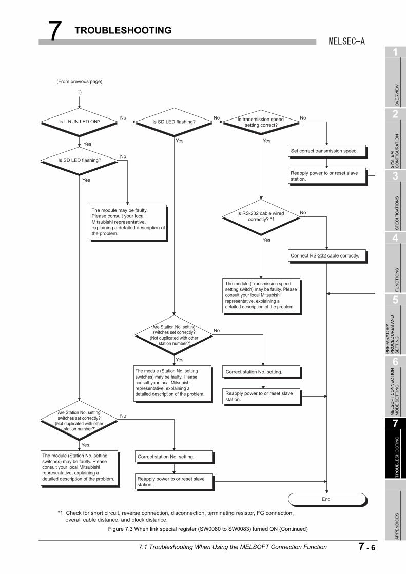
7 TROUBLESHOOTING
1
OV
ER
VIE
W
2
SY
ST
EM
C
ON
FIG
UR
AT
ION
3
SP
EC
IFIC
AT
ION
S
4
FU
NC
TIO
NS
5
PR
EP
AR
AT
OR
Y
PR
OC
ED
UR
ES
AN
D
SE
TT
ING
6
ME
LSO
FT
CO
NN
EC
TIO
N
MO
DE
SE
TT
ING
7
TR
OU
BL
ES
HO
OT
ING
AP
PE
ND
ICE
S
Figure 7.3 When link special register (SW0080 to SW0083) turned ON (Continued)
(From previous page)
1)
No
Yes
Yes
Yes
Yes
Yes
No
No
No
No
No
No
End
Is L RUN LED ON?
Is SD LED flashing?
Are Station No. setting switches set correctly?
(Not duplicated with other station number?)
Are Station No. setting switches set correctly?
(Not duplicated with other station number?)
Is SD LED flashing? Is transmission speed setting correct?
Is RS-232 cable wired correctly? *1
The module (Station No. setting switches) may be faulty. Please consult your local Mitsubishi representative, explaining a detailed description of the problem.
The module (Station No. setting switches) may be faulty. Please consult your local Mitsubishi representative, explaining a detailed description of the problem.
The module (Transmission speed setting switch) may be faulty. Please consult your local Mitsubishi representative, explaining a detailed description of the problem.
The module may be faulty. Please consult your local Mitsubishi representative, explaining a detailed description of the problem.
Reapply power to or reset slave station.
Correct station No. setting.
Reapply power to or reset slave station.
Correct station No. setting.
Reapply power to or reset slave station.
Connect RS-232 cable correctly.
Set correct transmission speed.Yes
Yes
*1 Check for short circuit, reverse connection, disconnection, terminating resistor, FG connection, overall cable distance, and block distance.
7.1 Troubleshooting When Using the MELSOFT Connection Function
7 - 6
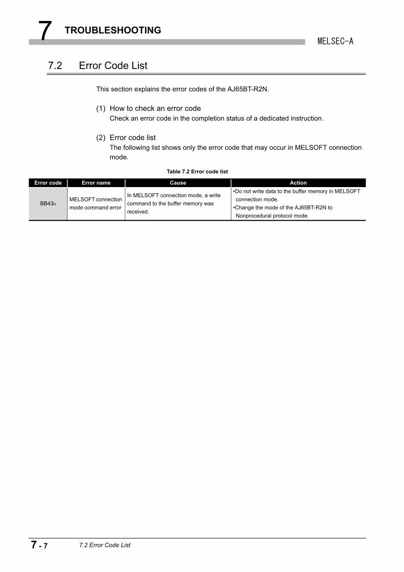
7 TROUBLESHOOTING
7.2 Error Code List
This section explains the error codes of the AJ65BT-R2N.
(1) How to check an error codeCheck an error code in the completion status of a dedicated instruction.
(2) Error code listThe following list shows only the error code that may occur in MELSOFT connection
mode.
Table 7.2 Error code list
Error code Error name Cause Action
BB43HMELSOFT connection
mode command error
In MELSOFT connection mode, a write
command to the buffer memory was
received.
•Do not write data to the buffer memory in MELSOFT
connection mode.
•Change the mode of the AJ65BT-R2N to
Nonprocedural protocol mode.
7 - 7 7.2 Error Code List
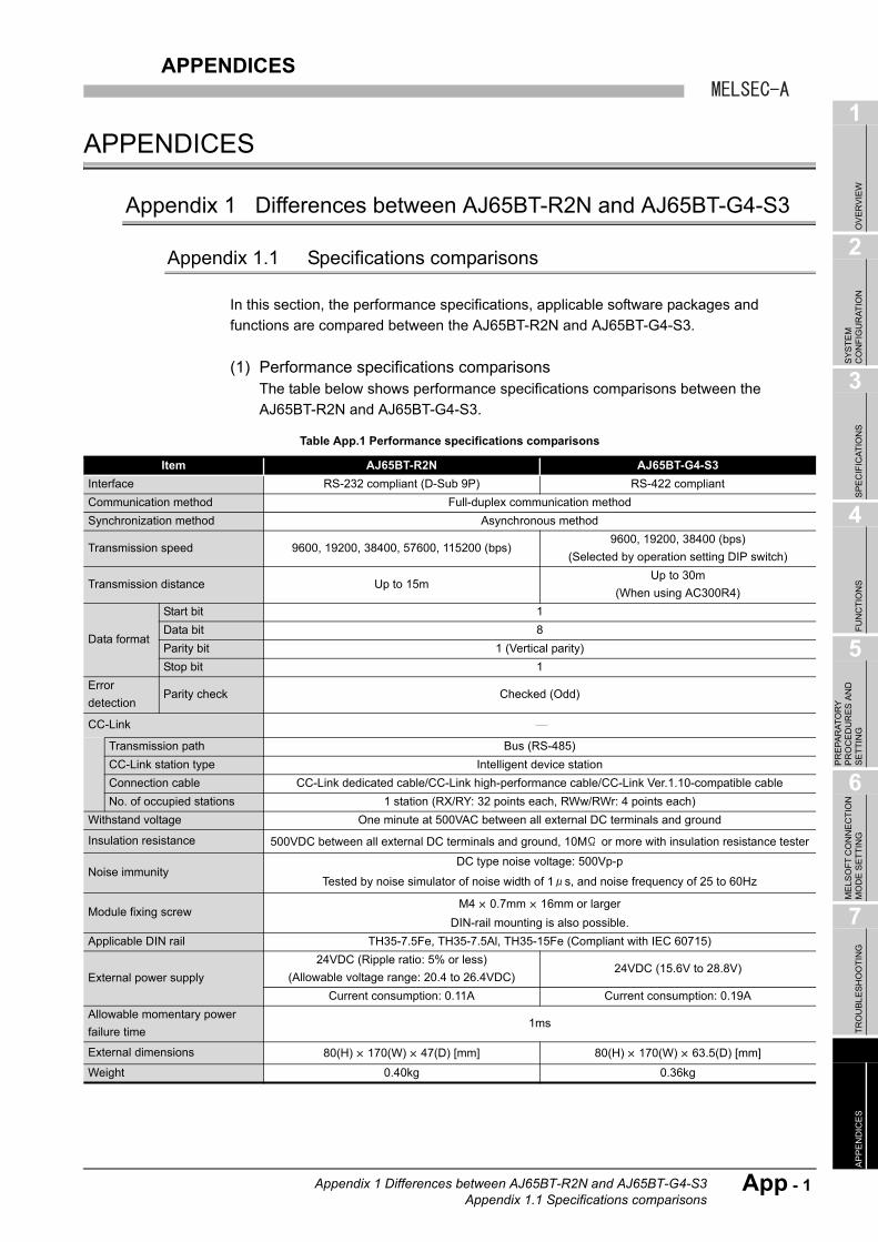
APPENDICES
1
OV
ER
VIE
W
2
SY
ST
EM
C
ON
FIG
UR
AT
ION
3
SP
EC
IFIC
AT
ION
S
4
FU
NC
TIO
NS
5
PR
EP
AR
AT
OR
Y
PR
OC
ED
UR
ES
AN
D
SE
TT
ING
6
ME
LSO
FT
CO
NN
EC
TIO
N
MO
DE
SE
TT
ING
7
TR
OU
BL
ES
HO
OT
ING
AP
PE
ND
ICE
S
APPENDICES
Appendix 1 Differences between AJ65BT-R2N and AJ65BT-G4-S3
Appendix 1.1 Specifications comparisons
In this section, the performance specifications, applicable software packages and
functions are compared between the AJ65BT-R2N and AJ65BT-G4-S3.
(1) Performance specifications comparisonsThe table below shows performance specifications comparisons between the
AJ65BT-R2N and AJ65BT-G4-S3.
Table App.1 Performance specifications comparisons
Item AJ65BT-R2N AJ65BT-G4-S3
Interface RS-232 compliant (D-Sub 9P) RS-422 compliant
Communication method Full-duplex communication method
Synchronization method Asynchronous method
Transmission speed 9600, 19200, 38400, 57600, 115200 (bps)9600, 19200, 38400 (bps)
(Selected by operation setting DIP switch)
Transmission distance Up to 15mUp to 30m
(When using AC300R4)
Data format
Start bit 1
Data bit 8
Parity bit 1 (Vertical parity)
Stop bit 1
Error
detectionParity check Checked (Odd)
CC-Link Transmission path Bus (RS-485)
CC-Link station type Intelligent device station
Connection cable CC-Link dedicated cable/CC-Link high-performance cable/CC-Link Ver.1.10-compatible cable
No. of occupied stations 1 station (RX/RY: 32 points each, RWw/RWr: 4 points each)
Withstand voltage One minute at 500VAC between all external DC terminals and ground
Insulation resistance 500VDC between all external DC terminals and ground, 10M or more with insulation resistance tester
Noise immunityDC type noise voltage: 500Vp-p
Tested by noise simulator of noise width of 1 s, and noise frequency of 25 to 60Hz
Module fixing screwM4 0.7mm 16mm or larger
DIN-rail mounting is also possible.
Applicable DIN rail TH35-7.5Fe, TH35-7.5Al, TH35-15Fe (Compliant with IEC 60715)
External power supply
24VDC (Ripple ratio: 5% or less)
(Allowable voltage range: 20.4 to 26.4VDC)24VDC (15.6V to 28.8V)
Current consumption: 0.11A Current consumption: 0.19A
Allowable momentary power
failure time1ms
External dimensions 80(H) 170(W) 47(D) [mm] 80(H) 170(W) 63.5(D) [mm]
Weight 0.40kg 0.36kg
Appendix 1 Differences between AJ65BT-R2N and AJ65BT-G4-S3Appendix 1.1 Specifications comparisons
App - 1
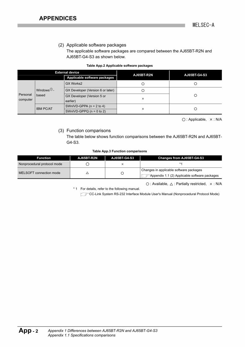
APPENDICES
(2) Applicable software packagesThe applicable software packages are compared between the AJ65BT-R2N and
AJ65BT-G4-S3 as shown below.
: Applicable, : N/A
(3) Function comparisonsThe table below shows function comparisons between the AJ65BT-R2N and AJ65BT-
G4-S3.
: Available, : Partially restricted, : N/A * 1 For details, refer to the following manual.
CC-Link System RS-232 Interface Module User's Manual (Nonprocedural Protocol Mode)
Table App.2 Applicable software packages
External deviceAJ65BT-R2N AJ65BT-G4-S3
Applicable software packages
Personal
computer
Windows -
based
GX Works2
GX Developer (Version 6 or later)
GX Developer (Version 5 or
earlier)
IBM PC/ATSWnIVD-GPPA (n = 2 to 4)
SWnIVD-GPPQ (n = 0 to 2)
Table App.3 Function comparisons
Function AJ65BT-R2N AJ65BT-G4-S3 Changes from AJ65BT-G4-S3
Nonprocedural protocol mode *1
MELSOFT connection modeChanges in applicable software packages
Appendix 1.1 (2) Applicable software packages
App - 2 Appendix 1 Differences between AJ65BT-R2N and AJ65BT-G4-S3Appendix 1.1 Specifications comparisons
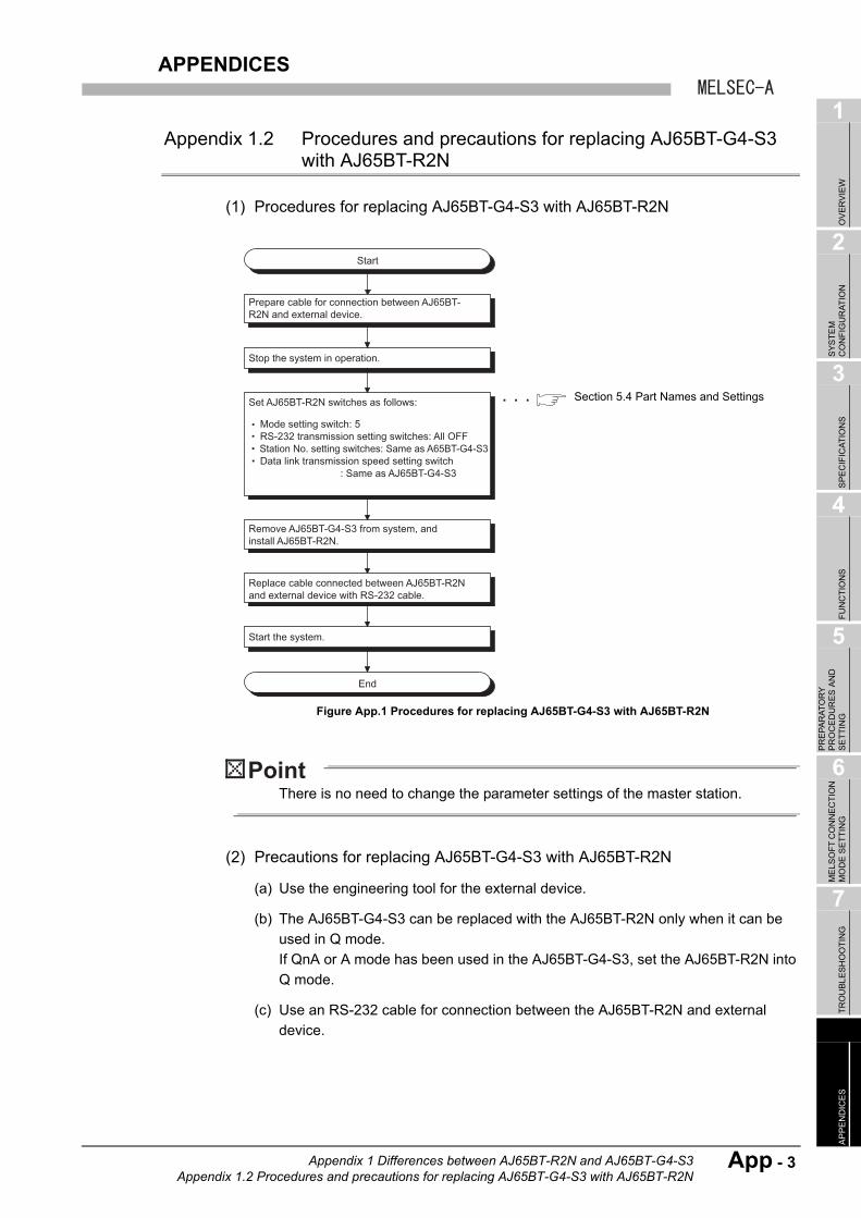
APPENDICES
1
OV
ER
VIE
W
2
SY
ST
EM
C
ON
FIG
UR
AT
ION
3
SP
EC
IFIC
AT
ION
S
4
FU
NC
TIO
NS
5
PR
EP
AR
AT
OR
Y
PR
OC
ED
UR
ES
AN
D
SE
TT
ING
6
ME
LSO
FT
CO
NN
EC
TIO
N
MO
DE
SE
TT
ING
7
TR
OU
BL
ES
HO
OT
ING
AP
PE
ND
ICE
S
Appendix 1.2 Procedures and precautions for replacing AJ65BT-G4-S3 with AJ65BT-R2N
(1) Procedures for replacing AJ65BT-G4-S3 with AJ65BT-R2N
There is no need to change the parameter settings of the master station.
(2) Precautions for replacing AJ65BT-G4-S3 with AJ65BT-R2N
(a) Use the engineering tool for the external device.
(b) The AJ65BT-G4-S3 can be replaced with the AJ65BT-R2N only when it can be
used in Q mode.
If QnA or A mode has been used in the AJ65BT-G4-S3, set the AJ65BT-R2N into
Q mode.
(c) Use an RS-232 cable for connection between the AJ65BT-R2N and external
device.
Figure App.1 Procedures for replacing AJ65BT-G4-S3 with AJ65BT-R2N
Start
Prepare cable for connection between AJ65BT-R2N and external device.
Remove AJ65BT-G4-S3 from system, and install AJ65BT-R2N.
Replace cable connected between AJ65BT-R2N and external device with RS-232 cable.
Start the system.
Set AJ65BT-R2N switches as follows:
Stop the system in operation.
End
: Same as AJ65BT-G4-S3
Mode setting switch: 5 RS-232 transmission setting switches: All OFF Station No. setting switches: Same as A65BT-G4-S3 Data link transmission speed setting switch
Section 5.4 Part Names and Settings
Appendix 1 Differences between AJ65BT-R2N and AJ65BT-G4-S3Appendix 1.2 Procedures and precautions for replacing AJ65BT-G4-S3 with AJ65BT-R2N
App - 3
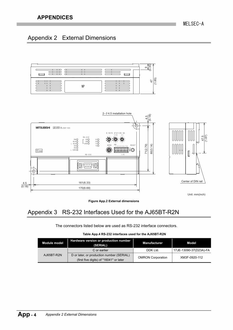
APPENDICES
Appendix 2 External Dimensions
Appendix 3 RS-232 Interfaces Used for the AJ65BT-R2N
The connectors listed below are used as RS-232 interface connectors.
Figure App.2 External dimensions
Table App.4 RS-232 interfaces used for the AJ65BT-R2N
Module modelHardware version or production number
(SERIAL)Manufacturer Model
AJ65BT-R2N
C or earlier DDK Ltd. 17JE-13090-37(D23A)-FA
D or later, or production number (SERIAL)
(first five digits) of "16041" or laterOMRON Corporation XM3F-0920-112
47.5
(1.8
7)
9(0
.35)
47(1
.85)
4.5(0.18)
161(6.33)
170(6.69)
2- 4.5 installation hole
4.5
(0.1
8)71
(2.7
9)
80(3
.14)
Center of DIN rail
Unit: mm(inch)
App - 4 Appendix 2 External Dimensions
APPENDICES
1
OV
ER
VIE
W
2
SY
ST
EM
C
ON
FIG
UR
AT
ION
3
SP
EC
IFIC
AT
ION
S
4
FU
NC
TIO
NS
5
PR
EP
AR
AT
OR
Y
PR
OC
ED
UR
ES
AN
D
SE
TT
ING
6
ME
LSO
FT
CO
NN
EC
TIO
N
MO
DE
SE
TT
ING
7
TR
OU
BL
ES
HO
OT
ING
AP
PE
ND
ICE
S
Memo
Appendix 3 RS-232 Interfaces Used for the AJ65BT-R2N
App - 5
Index - 1
INDEX
[A]
Accessible range ................................................... 4-4Applicable system.................................................. 2-2
Master module ................................................... 2-2Software package .............................................. 2-2Supported versions ............................................ 2-3
[B]
Buffer memory list................................................ 3-12
[D]
Differences between AJ65BT-R2N and AJ65BT-G4-S3 ..................................................App-1
Replacing .......................................................App-3Specifications comparisons............................App-1
[E]
Error code list ........................................................ 7-7
[G]
General specifications ........................................... 3-1
[H]
Hardware test ...................................................... 5-10
[M]
MELSOFT connection function.............................. 4-2MELSOFT connection mode setting...................... 6-1
[P]
Part names and settings........................................ 5-4Checking switch status with buffer memory ....... 5-9Data link transmission speed setting switch....... 5-7Indicator LEDs.................................................... 5-6Mode setting switch............................................ 5-7RS-232 transmission setting switches ............... 5-8
Performance Specifications................................... 3-2Preparatory Procedures and Setting ..................... 5-3
[R]
Remote I/O details ................................................. 3-9Remote I/O list ....................................................... 3-7Remote register list.............................................. 3-10RS-232
Cable specifications ........................................... 3-5Connector specifications .................................... 3-5
[S]
Setting When ACPU/QCPU (A mode) is Used.... 6-15Connection target setting ................................. 6-21Parameter setting............................................. 6-18Switch settings of each station......................... 6-16
Setting When LCPU is Used.................................. 6-2Connection target setting ................................... 6-6Parameter setting............................................... 6-4Switch settings of each station........................... 6-3
Setting When QCPU (Q mode)/QnACPU is Used............................................................................... 6-7
Connection target setting ................................. 6-13Parameter setting............................................. 6-10Switch settings of each station........................... 6-8
System configuration ............................................. 2-1
[T]
Troubleshooting ..................................................... 7-2Master station side troubleshooting ................... 7-4Troubleshooting list ............................................ 7-2
[W]
Wiring................................................................... 5-12CC-Link dedicated cable connection method... 5-12External device connection method ................. 5-13

WARRANTYPlease confirm the following product warranty details before using this product.
1. Gratis Warranty Term and Gratis Warranty Range
If any faults or defects (hereinafter "Failure") found to be the responsibility of Mitsubishi occurs during use of the product within the gratis warranty term, the product shall be repaired at no cost via the sales representative or Mitsubishi Service Company.However, if repairs are required onsite at domestic or overseas location, expenses to send an engineer will be solely at the customer's discretion. Mitsubishi shall not be held responsible for any re-commissioning, maintenance, or testing on-site that involves replacement of the failed module.[Gratis Warranty Term]The gratis warranty term of the product shall be for one year after the date of purchase or delivery to a designated place.Note that after manufacture and shipment from Mitsubishi, the maximum distribution period shall be six (6) months, and the longest gratis warranty term after manufacturing shall be eighteen (18) months. The gratis warranty term of repair parts shall not exceed the gratis warranty term before repairs.[Gratis Warranty Range](1) The range shall be limited to normal use within the usage state, usage methods and usage environment, etc.,
which follow the conditions and precautions, etc., given in the instruction manual, user's manual and caution labels on the product.
(2) Even within the gratis warranty term, repairs shall be charged for in the following cases.1. Failure occurring from inappropriate storage or handling, carelessness or negligence by the user. Failure
caused by the user's hardware or software design.2. Failure caused by unapproved modifications, etc., to the product by the user.3. When the Mitsubishi product is assembled into a user's device, Failure that could have been avoided if
functions or structures, judged as necessary in the legal safety measures the user's device is subject to or as necessary by industry standards, had been provided.
4. Failure that could have been avoided if consumable parts (battery, backlight, fuse, etc.) designated in the instruction manual had been correctly serviced or replaced.
5. Failure caused by external irresistible forces such as fires or abnormal voltages, and Failure caused by force majeure such as earthquakes, lightning, wind and water damage.
6. Failure caused by reasons unpredictable by scientific technology standards at time of shipment from Mitsubishi.
7. Any other failure found not to be the responsibility of Mitsubishi or that admitted not to be so by the user.
2. Onerous repair term after discontinuation of production
(1) Mitsubishi shall accept onerous product repairs for seven (7) years after production of the product is discontinued.Discontinuation of production shall be notified with Mitsubishi Technical Bulletins, etc.
(2) Product supply (including repair parts) is not available after production is discontinued.
3. Overseas service
Overseas, repairs shall be accepted by Mitsubishi's local overseas FA Center. Note that the repair conditions at each FA Center may differ.
4. Exclusion of loss in opportunity and secondary loss from warranty liability
Regardless of the gratis warranty term, Mitsubishi shall not be liable for compensation of damages caused by any cause found not to be the responsibility of Mitsubishi, loss in opportunity, lost profits incurred to the user by Failures of Mitsubishi products, special damages and secondary damages whether foreseeable or not, compensation for accidents, and compensation for damages to products other than Mitsubishi products, replacement by the user, maintenance of on-site equipment, start-up test run and other tasks.
5. Changes in product specifications
The specifications given in the catalogs, manuals or technical documents are subject to change without prior notice.

Microsoft, Windows, Windows Vista, Windows NT, Windows XP, Windows Server, Visio, Excel, PowerPoint,
Visual Basic, Visual C++, and Access are either registered trademarks or trademarks of Microsoft Corporation in
the United States, Japan, and other countries.
Intel, Pentium, and Celeron are either registered trademarks or trademarks of Intel Corporation in the United
States and other countries.
Ethernet is a registered trademark of Xerox Corp.
All other company names and product names used in this manual are either trademarks or registered
trademarks of their respective companies.
SH(NA)-080687ENG-C


SH(NA)-080687ENG-C(1410)MEE
MODEL: AJ65BT-R2N-U-MEL-E
MODEL CODE: 13JZ01
Specifications subject to change without notice.
When exported from Japan, this manual does not require application to theMinistry of Economy, Trade and Industry for service transaction permission.
HEAD OFFICE : TOKYO BUILDING, 2-7-3 MARUNOUCHI, CHIYODA-KU, TOKYO 100-8310, JAPANNAGOYA WORKS : 1-14 , YADA-MINAMI 5-CHOME , HIGASHI-KU, NAGOYA , JAPAN