Embed Size (px)
Citation preview
User,s ManualUser,s Manual
Mitsubishi Graphic Operation TerminalSpecifications subject to change without notice.
HEAD OFFICE : MITSUBISHI DENKI BLDG MARUNOUCHI TOKYO 100-0005 TELEX : J24532 CABLE MELCO TOKYONAGOYA WORKS : 1-14 , YADA-MINAMI 5 , HIGASHI-KU, NAGOYA , JAPAN
MODEL
MODELCODE
A8GT-J61BT13-U-E
13JL56
IB(NA)-66838-B(0106)MEE
A8GT-J61BT13 Type CC-Link Communication ModuleA8GT-J61BT13 Type CC-Link Communication Module
When exported from Japan, this manual does not require application to theMinistry of Economy, Trade and Industry for service transaction permission.
A - 1 A - 1
• SAFETY PRECAUTIONS •(Always read these instructions before using this equipment.)
Before using this product, please read this manual and the relevant manuals introduced in this manual
carefully and pay full attention to safety to handle the product correctly.
The instructions given in this manual are concerned with this product. For the safety instructions of the
programmable controller system, please read the CPU module user's manual.
In this manual, the safety instructions are ranked as "DANGER" and "CAUTION".
! DANGER
CAUTION!
Indicates that incorrect handling may cause hazardous conditions,resulting in death or severe injury.
Indicates that incorrect handling may cause hazardous conditions, resulting in medium or slight personal injury or physical damage.
Note that the ! CAUTION level may lead to a serious consequence according to the circumstances.
Always follow the instructions of both levels because they are important to personal safety.
Please save this manual to make it accessible when required and always forward it to the end user.
[Design Precautions]
! DANGER
• Some faults of this module may keep the outputs on or off. An external monitoring circuit should
therefore be provided to check for output signals which may lead to a serious accident.
Not doing so can cause an accident due to mis-output or misoperation.
• If a communication error (including cable disconnection) occurs during monitoring with the GOT,
communication between the GOT and master station is interrupted, disabling operation.
When using the GOT to configure a system, assume that a GOT communication error will occur
and configure a system in which switches used to perform significant operation for the system
are provided on any device other than the GOT.
Not doing so can cause an accident due to mis-output or misoperation.
! CAUTION
• Do not bundle control lines or communication cables with the main circuit, power or other lines
or lay them near these lines.
As a guideline, separate the cables at least 100mm(3.94inch).
Not doing so can cause misoperation due to noise.
A - 2 A - 2
[Mounting Precautions]
! DANGER
• Before mounting or dismounting the module to or from the GOT, always switch off GOT power
externally in all phases.
Not doing so can cause a module failure or misoperation.
! CAUTION
• Use this module in an environment that conforms to the general specifications given in the GOT
user's manual.
Not doing so can cause an electric shock, fire, misoperation, or product damage or deterioration.
• When mounting the module to the GOT, tighten the module fixing screws within the specified
torque range.
Undertightening can cause a drop, short circuit or misoperation.
Overtightening can cause a drop, short circuit or misoperation due to damaged screws or module.
[Wiring Precautions]
! DANGER
• Before starting wiring work, always switch GOT power off externally in all phases.
Not doing so can cause an electric shock, product damage or misoperation.
! CAUTION
• When switching power on or starting operation after mounting, wiring or other work, always fit
the terminal cover supplied to the product.
Not doing so can cause an electric shock, short circuit or failure.
• Always ground the FG terminal of the GOT power supply and the FG1 termial of this module to
the protective ground conducter.
Be sure to ground the GOT and this module separately.
Not doing so may cause an electric shock or misoperation.
• Before wiring the module, confirm the rated voltage and terminal arrangement of the product.
A fire or failure can occur if the power supply connected is different from the rating or wiring is
incorrect.
• Tighten the terminal screws within the specified torque range.
Undertightening can cause a short circuit or misoperation.
Overtightening can cause a short circuit or misoperation due to damaged screws or module.
• Ensure that foreign matters such as chips and wire off-cuts do not enter the module.
They can cause a fire, failure or misoperation.

A - 3 A - 3
[Wiring Precautions]
! CAUTION
• Always secure the communication cables connected to the module, e.g. run them in conduits or
clamp them.
Not doing so can damage the module or cables due to dangling, moved or accidentally pulled
cables or can cause misoperation due to cable contact fault.
• Do not hold the cable part when unplugging the communication cable connected to the module.
Disconnect the cable after loosening the screw in the part connected to the module.
If you pull the cable connected to the module, the module or cable can be damaged or
misoperation can occur due to cable connection fault.
[Test Operation Precautions]
! DANGER
• Do not output (switch on) any reserved signal among the output signals provided from the
master module to the GOT.
Doing so can cause the PLC system to misoperate.
[Startup/Maintenance Precautions]
! DANGER
• Do not touch the terminals while power is on.
Doing so can cause an electric shock or misoperation.
• Before starting cleaning or terminal screw retightening, always switch power off externally in all
phases.
Not doing so can cause a module failure or misoperation.
Undertightening can cause a drop, short circuit or misoperation.
Overtightening can cause a drop, short circuit or misoperation due to damaged screws or module.
! CAUTION
• Do not disassemble or modify the module.
Doing so can cause a failure, misoperation, injury or fire.
• Do not touch the conductive areas and electronic parts of the module.
Doing so can cause the module to misoperate or fail.
• Do not change any switch setting while power is on.
Doing so can cause a failure or misoperation.
• The module is made of resin. Do not drop it or subject it to strong impact.
Doing so can damage the module.
• Always make sure to touch the grounded metal to discharge the electricity charged in the body,
etc., before touching the module.
Failure to do so may cause a failure or malfunctions of the module.
A - 4 A - 4
[Disposal Precautions]
! CAUTION
• When disposing of the product, treat it as industrial waste.

A - 5 A - 5
REVISIONS* The manual number is given on the bottom left of the back cover.
Print Date * Manual Number RevisionMar., 1998 IB (NA) 66838-A First editionJun., 2001 IB (NA) 66838-B • The manual layout was rearranged.
Models added
GOT-A900 Series
Jun., 2003 IB (NA) 66838-C Partial corrections
Appendix 2
Partial additions
Section 2.2, Section 3.2, Section 4.1, Section 5.1, Section 6.3, Chapter 7
Jun., 2004 IB (NA) 66838-D Partial corrections
SAFETY PRECAUTIONS, About manuals
MODEL CODE change
Changed from 13JL56 to 1DM072
Japanese Manual Version IB-68944-E
This manual confers no industrial property rights or any rights of any other kind, nor does it confer any patentlicenses. Mitsubishi Electric Corporation cannot be held responsible for any problems involving industrial propertyrights which may occur as a result of using the contents noted in this manual.
1998 MITSUBISHI ELECTRIC CORPORATION

A - 6 A - 6
INTRODUCTION
Thank you for purchasing the Mitsubishi Graphic Operation Terminal.Before using the equipment, please read this manual carefully to develop full familiarity with the functionsand performance of the graphic operation terminal you have purchased, so as to ensure correct use.Please forward a copy of this manual to the end user.
CONTENTS
SAFETY PRECAUTIONS ..............................................................................................................................A- 1
About the manuals ..........................................................................................................................................A- 8
Abbreviations and generic theism in this manual ..........................................................................................A-10
1. OVERVIEW 1- 1 to 1- 2
2. SYSTEM CONFIGURATION 2- 1 to 2- 4
2.1 Overall Configuration............................................................................................................................... 2- 1
2.2 Instructions for System Configuration ..................................................................................................... 2- 2
3. SPECIFICATIONS 3- 1 to 3- 2
3.1 General Specifications............................................................................................................................. 3- 1
3.2 Performance Specifications..................................................................................................................... 3- 1
4. MONITORING SPECIFICATION 4- 1 to 4- 9
4.1 Monitoring Overview................................................................................................................................. 4- 1
4.2 Monitorable Access Range and Device Specifying Method ................................................................... 4- 7
4.2.1 Monitorable access range................................................................................................................ 4- 7
4.2.2 How to specify devices when creating the monitor screen............................................................. 4- 8
4.3 I/O Signals Transferred to/from the Master Module ............................................................................... 4- 9
4.4 Remote Register Assignment ................................................................................................................. 4- 9
5. PRE-OPERATION SETTINGS AND PROCEDURE 5- 1 to 5- 7
5.1 Pre-Operation Procedure ........................................................................................................................ 5- 1
5.2 Names of the Parts and Their Settings................................................................................................... 5- 3
5.3 Handling Instructions ............................................................................................................................... 5- 5
5.4 Mounting Procedures .............................................................................................................................. 5- 6
5.5 Wiring Method.......................................................................................................................................... 5- 7
A - 7 A - 7
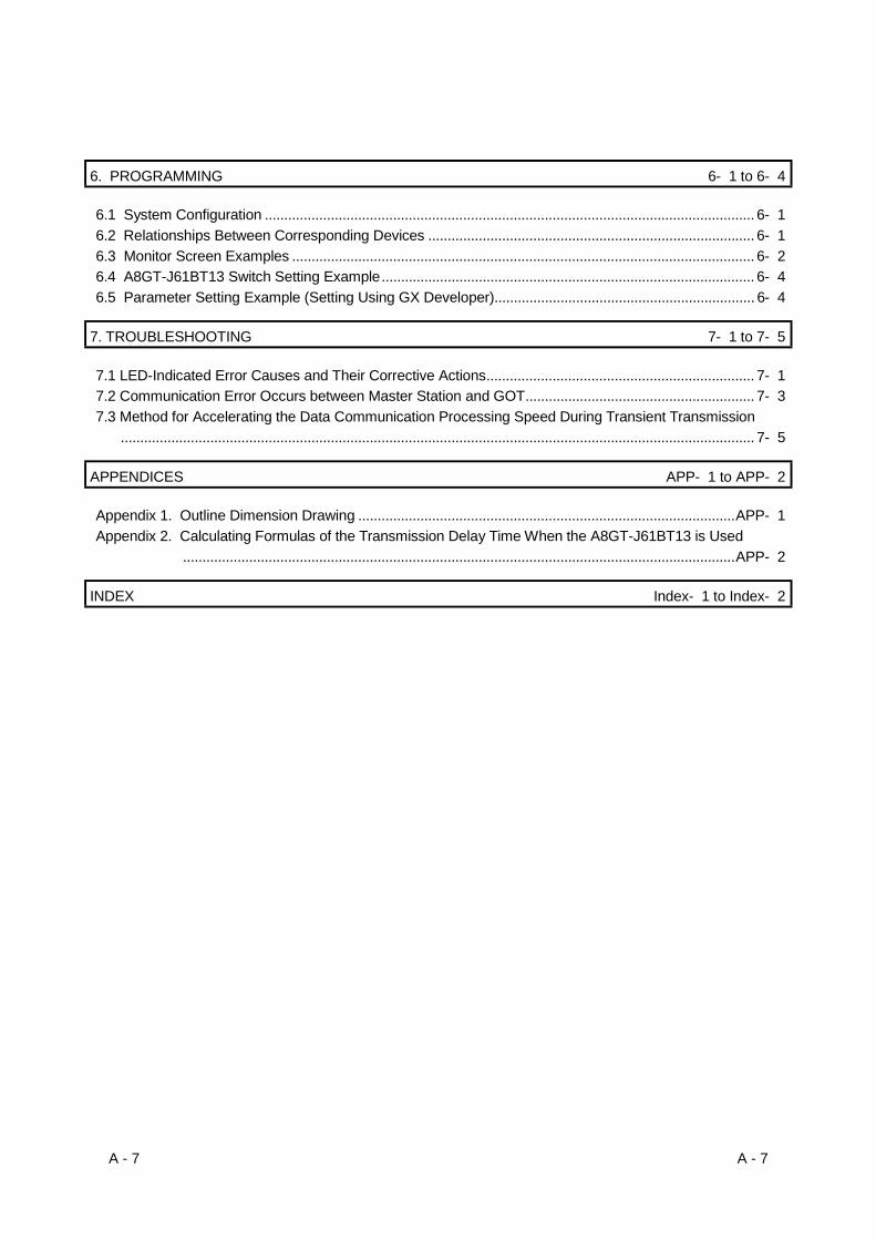
6. PROGRAMMING 6- 1 to 6- 4
6.1 System Configuration .............................................................................................................................. 6- 1
6.2 Relationships Between Corresponding Devices .................................................................................... 6- 1
6.3 Monitor Screen Examples ....................................................................................................................... 6- 2
6.4 A8GT-J61BT13 Switch Setting Example................................................................................................ 6- 4
6.5 Parameter Setting Example (Setting Using GX Developer)................................................................... 6- 4
7. TROUBLESHOOTING 7- 1 to 7- 5
7.1 LED-Indicated Error Causes and Their Corrective Actions..................................................................... 7- 1
7.2 Communication Error Occurs between Master Station and GOT........................................................... 7- 3
7.3 Method for Accelerating the Data Communication Processing Speed During Transient Transmission
................................................................................................................................................................... 7- 5
APPENDICES APP- 1 to APP- 2
Appendix 1. Outline Dimension Drawing .................................................................................................APP- 1
Appendix 2. Calculating Formulas of the Transmission Delay Time When the A8GT-J61BT13 is Used
..............................................................................................................................................APP- 2
INDEX Index- 1 to Index- 2

A - 8 A - 8
About Manuals
The following manuals are also related to this product.
In necessary, order them by quoting the details in the tables below.
Related Manuals
Manual NameManual Number(Model Code)
CC-Link System Master • Local Module type AJ61BT11/A1SJ61BT11 User's Manual
Describes the system configuration, performance specifications, functions, handling, wiring and trouble-
shooting of the AJ61BT11 and A1SJ61BT11. (Option)
IB-66721(13J872)
CC-Link System Master • Local Module type AJ61QBT11/A1SJ61QBT11 User's Manual
Describes the system configuration, performance specifications, functions, handling, wiring and trouble-
shooting of the AJ61QB11 and A1SJ61QBT11. (Option)
IB-66722(13J873)
CC-Link System Master • Local Module type QJ61BT11 User’s Manual
Describes the system configuration, performance specifications, functions, handling, wiring and
troubleshooting of the QJ61BT11 (Option)
SH-080016(13JL91)
A985GOT/A975GOT/A970GOT/A960GOT User's Manual
Explains the specifications, general system configuration, component devices, part names, option unit
loading methods, installation and wiring methods, maintenance and inspection methods, and error codes
of A985GOT/A975GOT/A970GOT/A960GOT unit. (Option)
SH-4005(1DM099)
A950GOT/A951GOT/A953GOT/A956GOT User's Manual
Explains the specifications, general system configuration, component devices, part names, option unit
loading methods, installation and wiring methods, maintenance and inspection methods, and error codes
of A950GOT/A951GOT/A953GOT/A956GOT unit. (Option)
SH-080018(1DM103)
A870GOT Graphic Operation Terminal User's Manual
This manual describes the specifications and performance of the A870GOT main unit as well as the
hardware configuration, procedures for installing optional units, operation in off-line mode, error codes,
and troubleshooting guidelines. (Option)
IB-66628(1DM050)
A850GOT Graphic Operation Terminal User's Manual
This manual describes the specifications and performance of the A850GOT main unit as well as the
hardware configuration, procedures for installing optional units, operation in off-line mode, error codes,
and troubleshooting guidelines. (Option)
IB-66669(1DM038)
GT Designer2 Version1 Operating Manual
Describes methods of operating GT Designer2 and transmitting data to GOT. (Option)
SH-080278E(1DM205)
GT Designer2 Version1 Reference Manual
Describes the specifications and settings of each object function used in GT Designer2 (Option)
SH-080251(1DM204)
GOT-A900 Series Operating Manual (GT Works2 Version1/GT Designer2 Version1compatible Extended • Option Functions Manual)
Provides the specifications of the utility, system monitoring, ladder monitoring, special function unit
monitoring, network monitoring functions and list editor functions available for the GOT-A900 series and
how to operate the dedicated monitor screen. (Option)
SH-080118(1DM185)
A - 9 A - 9
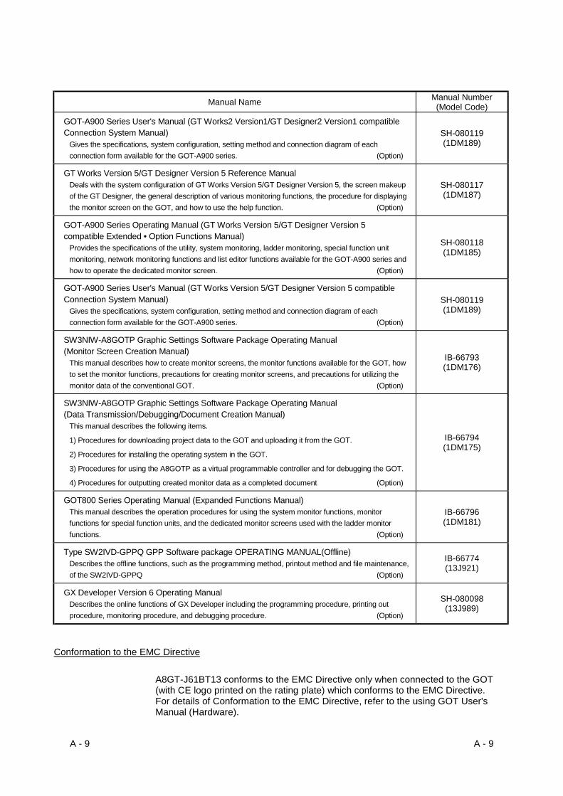
Manual NameManual Number(Model Code)
GOT-A900 Series User's Manual (GT Works2 Version1/GT Designer2 Version1 compatibleConnection System Manual)
Gives the specifications, system configuration, setting method and connection diagram of each
connection form available for the GOT-A900 series. (Option)
SH-080119(1DM189)
GT Works Version 5/GT Designer Version 5 Reference ManualDeals with the system configuration of GT Works Version 5/GT Designer Version 5, the screen makeup
of the GT Designer, the general description of various monitoring functions, the procedure for displaying
the monitor screen on the GOT, and how to use the help function. (Option)
SH-080117(1DM187)
GOT-A900 Series Operating Manual (GT Works Version 5/GT Designer Version 5compatible Extended • Option Functions Manual)
Provides the specifications of the utility, system monitoring, ladder monitoring, special function unit
monitoring, network monitoring functions and list editor functions available for the GOT-A900 series and
how to operate the dedicated monitor screen. (Option)
SH-080118(1DM185)
GOT-A900 Series User's Manual (GT Works Version 5/GT Designer Version 5 compatibleConnection System Manual)
Gives the specifications, system configuration, setting method and connection diagram of each
connection form available for the GOT-A900 series. (Option)
SH-080119(1DM189)
SW3NIW-A8GOTP Graphic Settings Software Package Operating Manual(Monitor Screen Creation Manual)
This manual describes how to create monitor screens, the monitor functions available for the GOT, how
to set the monitor functions, precautions for creating monitor screens, and precautions for utilizing the
monitor data of the conventional GOT. (Option)
IB-66793(1DM176)
SW3NIW-A8GOTP Graphic Settings Software Package Operating Manual(Data Transmission/Debugging/Document Creation Manual)
This manual describes the following items.
1) Procedures for downloading project data to the GOT and uploading it from the GOT.
2) Procedures for installing the operating system in the GOT.
3) Procedures for using the A8GOTP as a virtual programmable controller and for debugging the GOT.
4) Procedures for outputting created monitor data as a completed document (Option)
IB-66794(1DM175)
GOT800 Series Operating Manual (Expanded Functions Manual)This manual describes the operation procedures for using the system monitor functions, monitor
functions for special function units, and the dedicated monitor screens used with the ladder monitor
functions. (Option)
IB-66796(1DM181)
Type SW2IVD-GPPQ GPP Software package OPERATING MANUAL(Offline)Describes the offline functions, such as the programming method, printout method and file maintenance,
of the SW2IVD-GPPQ (Option)
IB-66774(13J921)
GX Developer Version 6 Operating ManualDescribes the online functions of GX Developer including the programming procedure, printing out
procedure, monitoring procedure, and debugging procedure. (Option)
SH-080098(13J989)
Conformation to the EMC Directive
A8GT-J61BT13 conforms to the EMC Directive only when connected to the GOT(with CE logo printed on the rating plate) which conforms to the EMC Directive.For details of Conformation to the EMC Directive, refer to the using GOT User'sManual (Hardware).

A - 10 A - 10
Abbreviations and generic terms in this manual
The following addreviations and symbols are used in this manual.Abbreviation/Generic Name/Term DescriptionCC-Link Abbreviation for the Control & Communication Link system
A8GT-J61BT13 Abbreviation of A8GT-J61BT13 type CC-Link communication moduleCC-Linkcommunicationmodule A8GT-J61BT15 Abbreviation of A8GT-J61BT15 type CC-Link communication module
A985GOT-V Generic term of A985GOT-TBA-V and A985GOT-TBD-VA985GOT Generic term of A985GOT-TBA, A985GOT-TBD and A985GOT-TBA-EU
A975GOTGeneric term of A975GOT-TBA-B, A975GOT-TBD-B, A975GOT-TBA, A975GOT-TBD and A975GOT-TBA-EU
A970GOTGeneric term of A970GOT-TBA-B A970GOT-TBD-B, A970GOT-TBA, A970GOT-TBD, A970GOT-SBA, A970GOT-SBD, A970GOT-LBA, A970GOT-LBD, A970GOT-TBA-EU and A970GOT-SBA-EU
A97*GOT Generic term of A975GOT and A970GOTA960GOT Generic term of A960GOT-EBA, A960GOT-EBD and A960GOT-EBA-EU
A956GOTGeneric term of A956GOT-TBD, A956GOT-SBD, A956GOT-LBD, A956GOT-TBD-M3, A956GOT-SBD-M3 and A956GOT-LBD-M3
GOT-A900Series
A956WGOT Abbreviation of A956WGOT-TBD
A870GOTGeneric term of A8GT-70GOT-EW, A8GT-70GOT-EB, A8GT-70GOT-SW, A8GT-70GOT-SB, A8GT-70GOT-TW, A8GT-70GOT-TB
A810GOT Abbreviation of A8GT-10GOT-CGOT800Series
A850GOTAbbreviation of A850GOT-LWD, A850GOT-LBD, A850GOT-SWD, A850GOT-SBD,A850GOT-LWD-M3, A850GOT-LBD-M3, A850GOT-SWD-M3, A850GOT-SBD-M3
GT Works2Version1 Generic term of SW1D5C-GTWK2-E
GT Designer2Version1 Generic term of SW1D5C-GTD2-E
GT WorksVersion 5
Abbreviation of SW5D5C-GTWORKS-E software package
GT DesignerVersion 5
Generic term of SW5D5C-GOTR-PACKE software package and SW5D5C-GOTR-PACKEV software package
Software
GX Developer Generic term of SW D5C-GPPW-E/SW D5F-GPPW-E software packagesGT Designer2 Abbreviation of image creation software GT Designer2 for GOT900GT Designer Abbreviation of image creation software GT Designer for GOT900Drawing
SoftwareSW NIW-A8GOTP
Abbreviation of SW NIW-A8GOTP software package
Personal computer Personal computer where the corresponding software package is installedMaster station Station which controls intelligent device, Local and Remote stations
Local stationStation which has a CPU and can communicate with the Master and other Localstations
Remote I/O station Slave station in the CC-Link system which can handle bit data onlyRemote device station Slave station in the CC-Link system which can handle bit data and word dataRemote station Generic name for remote I/O and remote device stations
Intelligent device stationSlave station in the CC-Link system which can make transient transmission, suchas the A8GT-J61BT13
Master/local moduleGeneric name for the QJ61BT11, AJ61BT11, AJ61QBT11, A1SJ61BT11 andA1SJ61QBT11
Master moduleGeneric name for the QJ61BT11, AJ61BT11, AJ61QBT11, A1SJ61BT11 andA1SJ61QBT11 when used as the Master station
Local moduleGeneric name for the QJ61BT11, AJ61BT11, AJ61QBT11, A1SJ61BT11 andA1SJ61QBT11 when used as Local stations
Cyclic transmissionTransmission method in which the contents of the remote inputs/outputs andremote registers are updated periodically
Transient transmission Transmission method in which communication is made at any timingRX Remote inputRY Remote outputRWw Remote register (write area)RWr Remote register (read area)

1 - 1 1 - 1
MELSEC-GOT1 OVERVIEW
1. OVERVIEW
This user's manual includes specifications, monitoring method, handling information,
programming method and other instructions of the A8GT-J61BT13 CC-Link
communication module (hereinafter referred to as the "A8GT-J61BT13") used in the
Control Communication Link (hereinafter referred to as "CC-Link") system.
By connecting the A8GT-J61BT13 module to the GOT, it can perform a monitoring
operation as an intelligent device station (the number of occupied stations may be
selected between 1 and 4) in the CC-Link system.
Intelligent device station
Remote device station
Local station Master station
CC-Link dedicatedcable
Monitoring byTransient Transmission
Monitoring byCyclic Transmission
All remote inputs/outputs and remote registers assigned to the Master station by CC-Link parameter setting can be monitored.
The PLC CPU on the Master/local station of the CC-Link system can be monitored.
(1) PLC CPU that allows monitoringNote that the types of the CPUs that can be monitored are different, depending
on the GOT used.
The following table lists the types of the CPUs that can be monitored.
: Can be monitored : Cannot be monitored
CPU Connected TO When the GOT-A900 Series is used When the GOT800 Series is used
(Q mode)QCPU
(A mode)
QnACPU
ACPU
Motion controller
1
1 - 2 1 - 2
MELSEC-GOT1 OVERVIEW
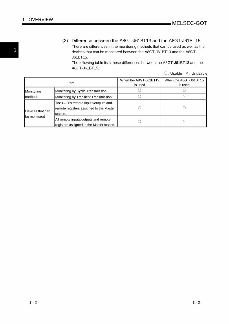
(2) Difference between the A8GT-J61BT13 and the A8GT-J61BT15There are differences in the monitoring methods that can be used as well as the
devices that can be monitored between the A8GT-J61BT13 and the A8GT-
J61BT15.
The following table lists these differences between the A8GT-J61BT13 and the
A8GT-J61BT15.
: Usable : Unusable
ItemWhen the A8GT-J61BT13
is usedWhen the A8GT-J61BT15
is used
Monitoring by Cyclic TransmissionMonitoring
methods Monitoring by Transient Transmission
The GOT’s remote inputs/outputs and
remote registers assigned to the Master
station.Devices that can
be monitoredAll remote inputs/outputs and remote
registers assigned to the Master station.
1
2 - 1 2 - 1
MELSEC-GOT2 SYSTEM CONFIGURATION
2. SYSTEM CONFIGURATION
This chapter describes the system configuration of the whole CC-Link system where
the A8GT-J61BT13 is used.
For equipment required for the GOT, refer to the user's manual of the GOT used.
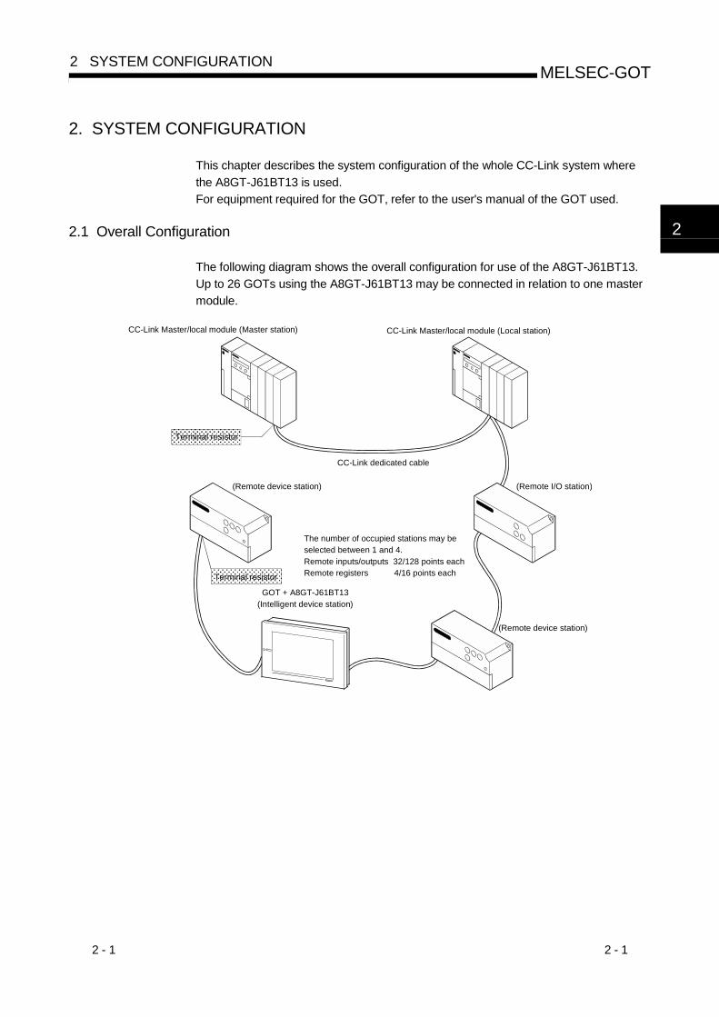
2.1 Overall Configuration
The following diagram shows the overall configuration for use of the A8GT-J61BT13.
Up to 26 GOTs using the A8GT-J61BT13 may be connected in relation to one master
module.
CC-Link Master/local module (Master station) CC-Link Master/local module (Local station)
CC-Link dedicated cable
(Remote I/O station)
(Remote device station)
(Remote device station)
GOT + A8GT-J61BT13(Intelligent device station)
��������������������������������������������������������������
Terminal resistor
The number of occupied stations may beselected between 1 and 4.Remote inputs/outputs 32/128 points eachRemote registers 4/16 points each
����������������������������������������������������������������
Terminal resistor
2

2 - 2 2 - 2
MELSEC-GOT2 SYSTEM CONFIGURATION
2.2 Instructions for System Configuration
When using the A8GT-J61BT13, follow these system configuration instructions.
(1) GOTs which can use the A8GT-J61BT13
The following GOT models can use the A8GT-J61BT13.
Name Model
A985GOT-V A985GOT-TBA-V, A985GOT-TBD-V
A985GOT A985GOT-TBA, A985GOT-TBD
A975GOT A975GOT-TBA(-B), A975GOT-TBD(-B)
A970GOTA970GOT-TBA(-B), A970GOT-TBD(-B), A970GOT-SBA,
A970GOT-SBD, A970GOT-LBA, A970GOT-LBD
A960GOT A960GOT-EBA, A960GOT-EBD
A956WGOT A956WGOT-TBD
A956GOT A956GOT-TBD(-M3), A956GOT-SBD(-M3), A956GOT-LBD(-M3)
A870GOTA8GT-70GOT-EW,A8GT-70GOT-EB,A8GT-70GOT-SW,A8GT-
70GOT-SB, A8GT-70GOT-TW,A8GT-70GOT-TB
A850GOTA850GOT-LWD(-M3),A850GOT-LBD(-M3),A850GOT-SWD(-M3),
A850GOT-SBD(-M3)
(2) Compatible software version
When creating the GOT screen or installing the operating system (OS), always use
the following software versions.
(a) GOT-A900 Series (Use either of the followings.)
GT Works2 Version1 software version 00A or later
GT Designer2 Version1 software version 00A or later
SW0D5C-GTWORKS-E software version A or later
SW1D5C-GOTRE-PACK software version A or later
(b) GOT800 Series
Graphics software: SW3NIW-A8GOTP software version E or later
OS program: SW3NIW-A8SYSP software version E or later
Special module monitor data: SW3NIW-A8GMDP
The software version can be confirmed on the rating plate of the floppy disk of
the product.
MITSUBISHI
MELSECSOFTWARE PACKAGE
MODEL SW3NIW-A8GOTP
DATE 9801A E 1/6
3.5inch
Indicates the software version. Indicates the software version.
9806A ADATE
SW NIW-A8 P GT Works2 Version1, GT Designer2 Version1 SW D5C-GTWORKS-E, SW D5C-GOTR-PACKE
2

2 - 3 2 - 3
MELSEC-GOT2 SYSTEM CONFIGURATION
(3) Communication Driver Installed in the GOT
Install the following communication driver in the GOT.
CC-Link communication unit Used Driver to Be Installed
A8GT-J61BT13 CC-LINK (ID)
(4) Master/local module which can use the GOT loaded with the A8GT-J61BT13
(a) QJ61BT11
The QJ61BT11 is supported by function version A.
(b) AJ61(Q) BT11/A1SJ61(Q)BT11
The GOT loaded with the A8GT-J61BT13 may be used with the Master/local
module whose function version is B (Dec. 1997) or later and whose software
version is J (Jan. 1998) or later.
The GOT cannot be used with the Master/local module whose function and
software note that monitoring by cyclic transmission may only be performed
when the version of the module used are earlier than the above.
The function version is indicated in the DATE field of the rating plate.
MITSUBISHI
MITSUBISHI ELECTRIC BD992D008H40
CPU UNITMODEL
DATE
PROGRAMMABLE CONTROLLER
DATE 9712 B
MITSUBISHI ELECTRIC CORPORATION JAPAN
BD992D008H40
9712 B
Year and monthof manufacture
Function version Year and monthof manufacture
Function version
<Large Type>
<Small Type>
The function version is only indicated on version B or later.
The software version is indicated on the module version seal on the module front.
AJ61BT11
TESTS0S1S2
156K625K2.5M5M10M
SDRD
A1SJ61BT11
RUNERR.MST
S MSTLOCAL
CPU R/W
SWM/S
PRMTIMELINE
L RUNL ERR.
ERROR
TEST
B RATE
RUNERR.MST
S MSTLOCAL
CPU R/WL RUNL ERR.
SW ERROR
M/SPRMTIMELINE
SDRD
STATION NO. MODE
Software version
Hardware version
Software version
Hardware version
2 - 4 2 - 4
MELSEC-GOT2 SYSTEM CONFIGURATION
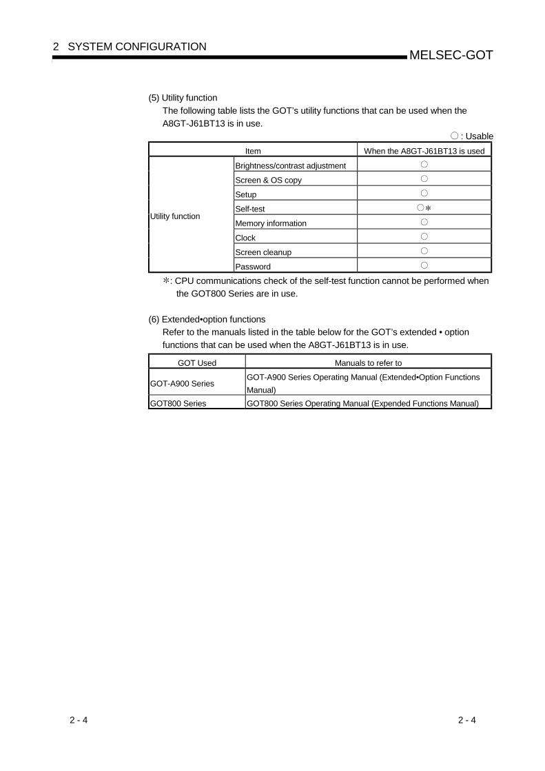
(5) Utility function
The following table lists the GOT’s utility functions that can be used when the
A8GT-J61BT13 is in use.
: Usable
Item When the A8GT-J61BT13 is used
Brightness/contrast adjustment
Screen & OS copy
Setup
Self-test
Memory information
Clock
Screen cleanup
Utility function
Password
: CPU communications check of the self-test function cannot be performed when
the GOT800 Series are in use.
(6) Extended•option functions
Refer to the manuals listed in the table below for the GOT’s extended • option
functions that can be used when the A8GT-J61BT13 is in use.
GOT Used Manuals to refer to
GOT-A900 SeriesGOT-A900 Series Operating Manual (Extended•Option Functions
Manual)
GOT800 Series GOT800 Series Operating Manual (Expended Functions Manual)
3 - 1 3 - 1
MELSEC-GOT3 SPECIFICATIONS
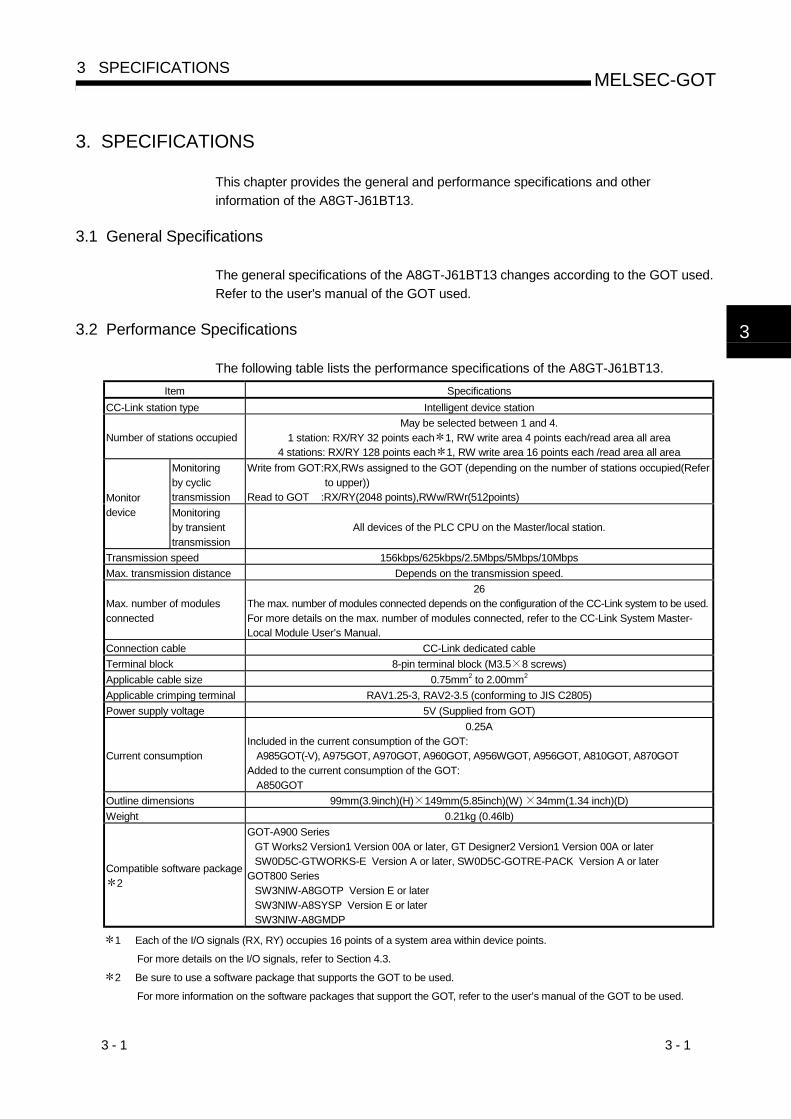
3. SPECIFICATIONS
This chapter provides the general and performance specifications and other
information of the A8GT-J61BT13.
3.1 General Specifications
The general specifications of the A8GT-J61BT13 changes according to the GOT used.
Refer to the user's manual of the GOT used.
3.2 Performance Specifications
The following table lists the performance specifications of the A8GT-J61BT13.
Item Specifications
CC-Link station type Intelligent device station
Number of stations occupiedMay be selected between 1 and 4.
1 station: RX/RY 32 points each 1, RW write area 4 points each/read area all area4 stations: RX/RY 128 points each 1, RW write area 16 points each /read area all area
Monitoringby cyclictransmission
Write from GOT:RX,RWs assigned to the GOT (depending on the number of stations occupied(Referto upper))
Read to GOT :RX/RY(2048 points),RWw/RWr(512points)Monitordevice Monitoring
by transienttransmission
All devices of the PLC CPU on the Master/local station.
Transmission speed 156kbps/625kbps/2.5Mbps/5Mbps/10Mbps
Max. transmission distance Depends on the transmission speed.
Max. number of modulesconnected
26The max. number of modules connected depends on the configuration of the CC-Link system to be used.For more details on the max. number of modules connected, refer to the CC-Link System Master-Local Module User’s Manual.
Connection cable CC-Link dedicated cable
Terminal block 8-pin terminal block (M3.5 8 screws)
Applicable cable size 0.75mm2 to 2.00mm2
Applicable crimping terminal RAV1.25-3, RAV2-3.5 (conforming to JIS C2805)
Power supply voltage 5V (Supplied from GOT)
Current consumption
0.25AIncluded in the current consumption of the GOT:
A985GOT(-V), A975GOT, A970GOT, A960GOT, A956WGOT, A956GOT, A810GOT, A870GOTAdded to the current consumption of the GOT:
A850GOT
Outline dimensions 99mm(3.9inch)(H) 149mm(5.85inch)(W) 34mm(1.34 inch)(D)
Weight 0.21kg (0.46lb)
Compatible software package2
GOT-A900 SeriesGT Works2 Version1 Version 00A or later, GT Designer2 Version1 Version 00A or laterSW0D5C-GTWORKS-E Version A or later, SW0D5C-GOTRE-PACK Version A or later
GOT800 SeriesSW3NIW-A8GOTP Version E or laterSW3NIW-A8SYSP Version E or laterSW3NIW-A8GMDP
1 Each of the I/O signals (RX, RY) occupies 16 points of a system area within device points.
For more details on the I/O signals, refer to Section 4.3.
2 Be sure to use a software package that supports the GOT to be used.
For more information on the software packages that support the GOT, refer to the user’s manual of the GOT to be used.
3

3 - 2 3 - 2
MELSEC-GOT3 SPECIFICATIONS
MEMO
3

4 - 1 4 - 1
MELSEC-GOT4 MONITORING SPECIFICATION
4. MONITORING SPECIFICATION
4.1 Monitoring Overview
When the A8GT-J61BT13 is used, the GOT has the following two monitoring methods.
Monitoring Method Monitoring by Transient Transmission Monitoring by Cyclic Transmission
ContentsDevices of the PLC CPU on the CC-Link system
Master/local station are specified and monitored.
Remote inputs/outputs and remote registers
assigned to the Master station by CC-Link
parameter setting are specified and monitored.
Advantage
CC-Link parameter setting sequence program 2 is
required but GOT communication sequence
program 2 is not needed. (For more information,
refer to Chapter 5.)
Data communication processing speed 1 is
high.
DisadvantageData communication processing speed 1 is lower
than that of cyclic transmission.
•Write from the GOT (read command from the
master station) can be performed to only the
remote outputs and remote registers of the
master station assigned to the GOT and to the
GOT's internal registers.
•GOT communication sequence program 2 is
necessary.
1 For details of the data communication processing speed (object display speed),
refer to the GT Designer2 Version1 Reference Manual or GT Works Version 5/GT
Designer Version 5 Reference Manual or SW3NIW-A8GOTP operating manual
(monitor screen creation).
2 This program is not needed if the CC-Link parameter setting sequence program
and GOT communication sequence program satisfy the following conditions.
• As the PLC CPU of the master station, use the QCPU (Q mode) or QnACPU
whose number given in the DATE field of the rating plate is "9707B" or later.
• Use GX Developer or SW2 -GPPW and make CC-Link parameter setting and
batch refresh device setting in the CC-Link setting on the package.
For details of the setting methods, refer to the CC-Link System Master/Local
Module User's Manual (Details).
POINTIn transient transmission, connection of several (five or more as a guideline)
intelligent device stations (GOTs and intelligent device units) reduces data
communication speed.
To raise data communication speed, increase the CC-Link system, for example,
and do not connect five or more intelligent device stations to a single CC-Link
system.
For more information on other methods for accelerating the data communication
speed, refer to Section 7.3.
4

4 - 2 4 - 2
MELSEC-GOT4 MONITORING SPECIFICATION
(1) Monitoring by transient transmissionThe devices of the PLC CPU on the CC-Link system Master/local station are
specified and monitored.
By merely specifying the devices to be monitored on the GOT, those devices can
be monitored without creating the GOT communication sequence program.
CC-Link dedicated cable
Monitorable
Master/local stationGOT communication sequence program
4
4 - 3 4 - 3
MELSEC-GOT4 MONITORING SPECIFICATION
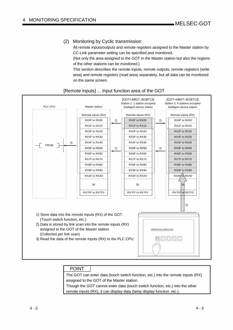
(2) Monitoring by Cyclic transmissionAll remote inputs/outputs and remote registers assigned to the Master station by
CC-Link parameter setting can be specified and monitored.
(Not only the area assigned to the GOT in the Master station but also the regions
of the other stations can be monitored.)
This section describes the remote inputs, remote outputs, remote registers (write
area) and remote registers (read area) separately, but all data can be monitored
on the same screen.
[Remote inputs] ... Input function area of the GOT
Remote inputs (RX)
RX0F to RX00
RX1F to RX10
RX2F to RX20
RX3F to RX30
RX4F to RX40
RX5F to RX50
RX6F to RX60
RX7F to RX70
RX8F to RX80
RX9F to RX90
RXAF to RXA0
RX7FF to RX7F0
to
Master stationPLC CPU
Remote inputs (RX) Remote inputs (RX)
[GOT+A8GT-J61BT13]Station 1: 1 station occupied
Intelligent device station
[GOT+A8GT-J61BT13]Station 2: 4 stations occupied
Intelligent device station
2)
2)
2)
2)
3)FROM
OPERATION DIRECTIVE
1)
1) Store data into the remote inputs (RX) of the GOT. (Touch switch function, etc.)2) Data is stored by link scan into the remote inputs (RX) assigned to the GOT of the Master station. (Collected per link scan)3) Read the data of the remote inputs (RX) to the PLC CPU.
RX2F to RX20
RX3F to RX30
RX4F to RX40
RX5F to RX50
RX6F to RX60
RX7F to RX70
RX8F to RX80
RX9F to RX90
RXAF to RXA0
RX7FF to RX7F0
to
RX0F to RX00
RX1F to RX10
RX2F to RX20
RX3F to RX30
RX4F to RX40
RX5F to RX50
RX6F to RX60
RX7F to RX70
RX8F to RX80
RX9F to RX90
RXAF to RXA0
RX7FF to RX7F0
to
RX0F to RX00
RX1F to RX10
POINTThe GOT can enter data (touch switch function, etc.) into the remote inputs (RX)
assigned to the GOT of the Master station.
Though the GOT cannot enter data (touch switch function, etc.) into the other
remote inputs (RX), it can display data (lamp display function, etc.).
4 - 4 4 - 4
MELSEC-GOT4 MONITORING SPECIFICATION
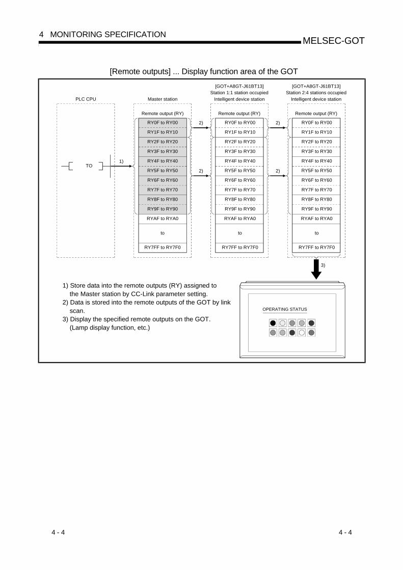
[Remote outputs] ... Display function area of the GOT
Remote output (RY)
RY0F to RY00
RY1F to RY10
RY2F to RY20
RY3F to RY30
RY4F to RY40
RY5F to RY50
RY6F to RY60
RY7F to RY70
RY8F to RY80
RY9F to RY90
RYAF to RYA0
RY7FF to RY7F0
to
Master stationPLC CPU
Remote output (RY) Remote output (RY)
[GOT+A8GT-J61BT13]Station 1:1 station occupied
Intelligent device station
[GOT+A8GT-J61BT13]Station 2:4 stations occupied
Intelligent device station
2)
2)
2)
2)
1)TO
3)
1) Store data into the remote outputs (RY) assigned to the Master station by CC-Link parameter setting.2) Data is stored into the remote outputs of the GOT by link scan.3) Display the specified remote outputs on the GOT. (Lamp display function, etc.)
RY0F to RY00
RY1F to RY10
RY2F to RY20
RY3F to RY30
RY4F to RY40
RY5F to RY50
RY6F to RY60
RY7F to RY70
RY8F to RY80
RY9F to RY90
RYAF to RYA0
RY7FF to RY7F0
to
RY0F to RY00
RY1F to RY10
RY2F to RY20
RY3F to RY30
RY4F to RY40
RY5F to RY50
RY6F to RY60
RY7F to RY70
RY8F to RY80
RY9F to RY90
RYAF to RYA0
RY7FF to RY7F0
to
OPERATING STATUS

4 - 5 4 - 5
MELSEC-GOT4 MONITORING SPECIFICATION
[Remote registers (read area)] ... Input function area of the GOT
Remote registers (RWr)
RWr0 to RWr3
RWr4 to RWr7
RWr8 to RWrB
RWrC to RWrF
RWr10 to RWr13
RWr14 to RWr17
RWrFC to RWrFF
to
Master stationPLC CPU
[GOT+A8GT-J61BT13]Station 1: 1 station occupied
Intelligent device station
[GOT+A8GT-J61BT13]Station 2: 4 stations occupied
Intelligent device station
2)
2)
2)
2)3)
FROM
1)
1) Store data into the remote registers (read area) of the GOT. (Value entry function, etc.)2) Data is stored by link scan into the remote registers (read area) assigned to the GOT of the Master station. (Collected per link scan)3) Read the data of the remote registers (read area) to the PLC CPU.
Remote registers (RWr) Remote registers (RWr)
PRODUCTION AMOUNT DIRECTIVE
LINE 1
LINE 2
LINE 3
12050
RWr0 to RWr3
RWr4 to RWr7
RWr8 to RWrB
RWrC to RWrF
RWr10 to RWr13
RWr14 to RWr17
RWrFC to RWrFF
to
RWr0 to RWr3
RWr4 to RWr7
RWr8 to RWrB
RWrC to RWrF
RWr10 to RWr13
RWr14 to RWr17
RWrFC to RWrFF
to
POINTThe GOT can enter data (value entry function, etc.) into the remote registers (read
area) assigned to the GOT of the Master station.
Though the GOT cannot enter data (value entry function, etc.) into the other remote
registers (read area), it can display data (value display function, etc.).

4 - 6 4 - 6
MELSEC-GOT4 MONITORING SPECIFICATION
[Remote registers (write area)] ... Display function area of the GOT
Remote registers (RWw)
RWw0 to RWw3
RWw4 to RWw7
RWw8 to RWwB
RWwC to RWwF
RWw10 to RWw13
RWw14 to RWw17
RWwFC to RWwFF
to
Master stationPLC CPU
[GOT+A8GT-J61BT13]Station 1: 1 station occupied
Intelligent device station
2)
2)
2)
2)1)
to
Remote registers (RWw) Remote registers (RWw)
3)
1) Store data into the remote registers (write area) assigned to the Master station by CC-Link parameter setting.2) Data is stored into the remote registers (write area) of the GOT by link scan.3) Display the specified remote registers (write area) on the GOT. (Value display function, etc.)
[GOT+A8GT-J61BT13]Station 2: 4 stations occupied
Intelligent device station
RWw0 to RWw3
RWw4 to RWw7
RWw8 to RWwB
RWwC to RWwF
RWw10 to RWw13
RWw14 to RWw17
RWwFC to RWwFF
to
RWw0 to RWw3
RWw4 to RWw7
RWw8 to RWwB
RWwC to RWwF
RWw10 to RWw13
RWw14 to RWw17
RWwFC to RWwFF
to
PRODUCTION CONDITION
LINE 1LINE 2
LINE 3
115
46
74

4 - 7 4 - 7
MELSEC-GOT4 MONITORING SPECIFICATION
4.2 Monitorable Access Range and Device Specifying Method
4.2.1 Monitorable access range
(1) Monitorable access range for Transient transmission
The GOT can monitor all devices of the PLC CPUs of the Master/local stations and
the GOT internal devices in the CC-Link system.
��������������������������������������������������������������������������������������������������������������������������������������������������������������������������������������������������������������������������������������������������������������������������������������������������������������������������������������������������������������������������������������������������������������������������������������������������������������������������������������������������������������������������������������������������������������������������������������������������������������������������������������������������������������������������������������������������������������������������������������������������������������������������������������������������������������������������������������������������������������������������������������������������������������������������������������������������������������������������������������������������������������������������������������������������������������������������������������������������������������������������������������������������������������������������������������������������������������������������������������������������������������������������������������������������������������������������������������������������������������������������������������������������������������������������������������������������������������������������������������������������������������������������������������������������������������������������������������������������� �������������������� �������������������� �������������������� ������������������ ������������������ ������������������ ������������������ ������������������ ������������������ ������������������ ����������������� ���������������� ���������������� ���������������� ���������������� ���������������� ���������������� ���������������� ����������������� ����������������� ����������������� ���������������� ���������������� ���������������� ��������������� ��������������� ��������������� ��������������� ��������������� ��������������� ���������������� ���������������� ���������������� ���������������� ���������������� ���������������� ����������������
�������������������������������� ���������������� ���������������� ��������������� ��������������� ��������������� ��������������� ��������������� �������������� �������������� �������������� �������������� �������������� �������������� �������������� �������������� �������������� �������������� �������������� �������������� �������������� �������������� �������������� �������������� �������������� �������������� �������������� �������������� �������������� �������������� �������������� �������������� �������������� �������������� �������������� �������������� �������������� �������������� �������������� �������������� �������������� �������������� �������������� �������������� �������������� �������������� �������������� �������������� ������������� ������������� ������������� ������������� ������������� ������������� ������������� ������������� ������������� ������������� ������������� ������������� ������������� ������������� ������������� �������������� �������������� �������������� �������������� �������������� �������������� �������������� �������������� �������������� �������������� �������������� �������������� �������������� �������������� �������������� �������������� �������������� �������������� �������������� �������������� �������������� �������������� �������������� �������������� �������������� �������������� �������������� �������������� �������������� �������������� �������������� �������������� ��������������
���������������������������� �������������� �������������� �������������� �������������� ��������������� ��������������� ��������������� ��������������� ��������������� ��������������� ��������������� ���������������� ���������������� ���������������� ���������������� ���������������� ���������������� ���������������� ���������������� ��������������� ��������������� ��������������� ��������������� ��������������� ��������������� ���������������� ���������������� ���������������� ���������������� ���������������� ����������������� ����������������� ����������������� ���������������� ���������������� ���������������� ���������������� ���������������� ����������������� ����������������� ����������������� ������������������ ������������������ ������������������ ������������������ ������������������ ������������������� ������������������� �������������������� �������������������� �������������������� ��������������������������������������������������������������������������������������������������������������������������������������������������������������������������������������������������������������������������������������������������������������������������������������������������������������������������������������������������������������������������������������������������������������������������������������������������������������������������������������������������������������������������������������������������������������������������������������������������������������������������������������������������������������������������������������������������������������������������������������������������������������������������������������������������������������������������������������������������������������������������������������������������������
������������������������������������������������������������������������������������������������������������������������������������������������������������������������������������������������������������������������������������������������������������������������������������������������������������������������������������������������������������������������������������������������������������������������������������������������������������������������������������������������������������������������������������������������������������������������������������������������������������������������������������������������������������������
������������������������������������������������������������������������������������������������������������������������������������������������������������������������������������������������������������������������������������������������������������������������������������������������������������������������������������������������������������������������������������������������������������������������������������������������������������������������������������������������������������������������������������������������������������������������������������������������������������������������������������������������������������������������������������������������������������������������������������������������������������������������������������������������������������������������������������������������������������������������������������������������������������������������������������������������������������������������������������������������������������������������������������������������������������������������������������������������������������������������������������������������������������������������������������������������������������������������������������������������������������������������������������������������������������������������������������������������������������������������������������������������������������������������������������������������������������������������������������������������������������������������������������������������������� �������������������� �������������������� ������������������� ������������������ ������������������ ������������������ ������������������ ������������������� ������������������ ������������������ ������������������ ������������������ ������������������ ������������������ ������������������ ������������������ ������������������ ����������������� ����������������� ���������������� ���������������� ���������������� ���������������� ���������������� ���������������� ���������������� ���������������� ���������������� ���������������� ���������������� ���������������� ���������������� ���������������� ��������������� �������������� �������������� �������������� �������������� ��������������
���������������������������� �������������� �������������� �������������� �������������� �������������� �������������� �������������� �������������� �������������� �������������� ��������������� ��������������� ��������������� ��������������� ���������������� ���������������� ���������������� ���������������� ��������������� �������������� �������������� �������������� �������������� �������������� �������������� �������������� �������������� �������������� �������������� �������������� �������������� �������������� �������������� �������������� �������������� �������������� �������������� �������������� �������������� �������������� �������������� �������������� �������������� �������������� �������������� �������������� �������������� �������������� �������������� �������������� �������������� �������������� �������������� �������������� �������������� �������������� �������������� �������������� �������������� �������������� �������������� �������������� �������������� �������������� �������������� �������������� �������������� �������������� �������������� �������������� �������������� �������������� �������������� �������������� �������������� �������������� �������������� �������������� �������������� �������������� �������������� �������������� �������������� �������������� �������������� �������������� �������������� �������������� �������������� ��������������� ���������������� ���������������� ���������������� ���������������� ����������������
������������������������������ ��������������� �������������� �������������� �������������� �������������� �������������� �������������� �������������� �������������� �������������� �������������� �������������� �������������� �������������� �������������� �������������� �������������� �������������� ��������������� ���������������� ���������������� ���������������� ���������������� ���������������� ���������������� ���������������� ���������������� ���������������� ���������������� ���������������� ���������������� ���������������� ���������������� ���������������� ������������������ ������������������ ������������������ ������������������ ������������������ ������������������ ������������������ ������������������ ������������������ ������������������� ������������������ ������������������ ������������������ ������������������ ������������������ ������������������� �������������������� �������������������� �����������������������������������������������������������������������������������������������������������������������������������������������������������������������������������������������������������������������������������������������������������������������������������������������������������������������������������������������������������������������������������������������������������������������������������������������������������������������������������������������������������������������������������������������������������������������������������������������������������������������������������������������������������������������������������������������������������������������������������������������������������������������������������������������������������������������������������������������������������������������������������
���������������������������������������������������������������������������������������������������������������������������������������������������������������������������������������������������������������������������������������������������������������������������������������������������������������������������������������������������������������������������������������������������������������������������������������������������������������������������������������������������������������������������������������������������������������������������������������������������������������������������������������������������������������
Intelligent device station Local station Master station
CC-Link dedicated cable
����������������������������������������������������������������������������������������������������������������������������������������������������������������������������������������������������������������������������������������������������������������������������������������������������������������������������������������������������������������������������������������������������������������������������������������������������������������������������������������������������������������������������������������������������������������������������������������������������������������������������������������������������������������������������������������������
Monitorable
(2) Monitorable access range for Cyclic transmission
The GOT can monitor all remote inputs/outputs, remote registers and GOT internal
device assigned to the Master station by CC-Link parameter setting.
Among them, the GOT can write data (read command from the Master station) to
only the RX, RWr and GOT internal device assigned to the GOT of the Master
station.
The devices that can be monitored are indicated below.
Monitorable Devices Setting Device Range
Remote inputs (RX) RX0 to RX7FF
Remote outputs (RY) RY0 to RY7FF
Specified bits (RWw) of remote registers (write area) RWw0 to RWwFF
Specified bits (RWr) of remote registers (read area) RWr0 to RWrFF
GOT bit register (GB) GB64 to GB1023
Bit
Bit designation of GOT data register (GD) GD64 to GD1023
Remote registers (write area) (RWw) RWw0 to RWwFF
Remote registers (read area) (RWr) RWr0 to RWrFF
GOT data register (GD) GD64 to GD1023
Converting GOT bit register to word (GB) 1 GB64 to GB1023
Word
GOT special register (GS) 1 GS0 to GS511
Can be monitored only when the GOT-A900 Series is used.
4 - 8 4 - 8
MELSEC-GOT4 MONITORING SPECIFICATION
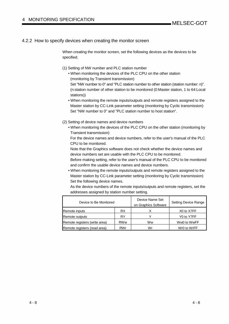
4.2.2 How to specify devices when creating the monitor screen
When creating the monitor screen, set the following devices as the devices to be
specified.
(1) Setting of NW number and PLC station number
• When monitoring the devices of the PLC CPU on the other station
(monitoring by Transient transmission)
Set "NW number to 0" and "PLC station number to other station (station number: n)".
(n:station number of other station to be monitored (0:Master station, 1 to 64:Local
stations))
• When monitoring the remote inputs/outputs and remote registers assigned to the
Master station by CC-Link parameter setting (monitoring by Cyclic transmission)
Set "NW number to 0" and "PLC station number to host station".
(2) Setting of device names and device numbers
• When monitoring the devices of the PLC CPU on the other station (monitoring by
Transient transmission)
For the device names and device numbers, refer to the user's manual of the PLC
CPU to be monitored.
Note that the Graphics software does not check whether the device names and
device numbers set are usable with the PLC CPU to be monitored.
Before making setting, refer to the user's manual of the PLC CPU to be monitored
and confirm the usable device names and device numbers.
• When monitoring the remote inputs/outputs and remote registers assigned to the
Master station by CC-Link parameter setting (monitoring by Cyclic transmission)
Set the following device names.
As the device numbers of the remote inputs/outputs and remote registers, set the
addresses assigned by station number setting.
Device to Be MonitoredDevice Name Set
on Graphics SoftwareSetting Device Range
Remote inputs RX X X0 to X7FF
Remote outputs RY Y Y0 to Y7FF
Remote registers (write area) RWw Ww Ww0 to WwFF
Remote registers (read area) RWr Wr Wr0 to WrFF

4 - 9 4 - 9
MELSEC-GOT4 MONITORING SPECIFICATION
4.3 I/O Signals Transferred to/from the Master Module
The following table lists the I/O signals assigned to the GOT.
The I/O signals differ according to the set number of occupied stations (1 or 4 stations).
n in the table indicates the address assigned to the Master module by station number
setting.
Signal Direction:GOT Master module Signal Direction:Master module GOT
Device number Device number
Number of occupied stations Number of occupied stations
1 station 4 stations
Signal name
1 station 4 stations
Signal name
RXn0 to RXnFRXn0 to
RX(n+6)FUser area RYn0 to RYnF
RYn0 to
RY(n+6)FUser area
RX(n+1)0 to
RX(n+1)A
RX(n+7)0 to
RX(n+7)AReserved
RY(n+1)0 to
RY(n+1)A
RY(n+7)0 to
RY(n+7)A
RX(n+1)B RX(n+7)BRemote ready
flag 1RY(n+1)B RY(n+7)B
RX(n+1)C to
RX(n+1)F
RX(n+7)C to
RX(n+7)FReserved
RY(n+1)C to
RY(n+1)F
RY(n+7)C to
RY(n+7)F
Reserved
1 The remote ready flag is on during startup of the GOT.
It switches on when GOT power is switched on, hardware reset is made, or the
GOT is ready to operate.
If GOT power is on, the remote ready flag is off when offline operation is performed
(during OS installation or screen data downloading) or while initial processing is
executed.
Use it for the interlock ladder when writing or reading data to or from the CC-Link
Master station.
DANGER • Among the output signals from the Master module to the GOT, do not output the
reserved signals.
Doing so can cause the PLC system to misoperate.
4.4 Remote Register Assignment
The following is the assignment of the remote registers of the GOT.
The remote registers differ according to the set number of occupied stations (1 or 4
stations).
All areas are use areas.
m and n in the table indicate the addresses assigned to the Master module by station
number setting.
Addresses
Number of occupied stationsTransfer Direction
1 station 4 stations
Description Default Value
Master station
GOT
RWwm to RWwm+3 RWwm to RWwm+F User write area 0
GOT
Master station
RWrn to RWrn+3 RWrn to RWrn+F User read area 0

5 - 1 5 - 1
MELSEC-GOT5 PRE-OPERATION SETTINGS AND PROCEDURE
5. PRE-OPERATION SETTINGS AND PROCEDURE
This chapter provides a pre-operation procedure, the names of the parts and their
settings, and the wiring method for the A8GT-J61BT13.
5.1 Pre-Operation Procedure
The following flowchart indicates a pre-operation procedure.
(1) Procedure up to downloading of monitor screen data to the GOT
Install the OS program installed in the Personal computer into the GOT.1) Install ROM_BIOS. ROM_BIOS is factory-installed into the GOT. It must be installed only when the version of ROM_BIOS installed in the GOT is older than that of ROM_BIOS currently installed in the personal computer.2) When ROM_BIOS installation is complete, reset the GOT power supply.3) Install the basic OS, communication driver "CC-Link (ID)" and optional function OS into the GOT.4) When installation is complete, reset the GOT power supply.
Supply power to the GOT.
Connect the GOT and Personal computer with the RS-232C cable.
Wire the GOT power supply.
Start
Load the A8GT-J61BT13 to the GOT.
Set the switches of the A8GT-J61BT13.
Wire the CC-Link dedicated cable.
Load and wire the optional module.
Switch on the system with which the GOT is connected.
Download the monitor screen data created on the personal computer to the GOT.
When downloading is complete, start monitoring.
Complete
Refer to the user's manual of the GOT used
⋅⋅⋅⋅⋅Refer to the GT Designer2 Version1 Operating Manual or the GT Works Version 5 / GT Designer Version 5 Referrence Manual or the SW3NIW-A8GOTP operating manual (Data transmission/Debugging/Document Creation Manual)
⋅⋅⋅⋅⋅Refer to Section 5.4
⋅⋅⋅⋅⋅Refer to Section 5.2
⋅⋅⋅⋅⋅Refer to Section 5.5
⋅⋅⋅⋅⋅Refer to the user's manual of the GOT used
⋅⋅⋅⋅⋅Refer to the GT Designer2 Version1 Operating Manual or the GT Works Version 5 / GT Designer Version 5 Referrence Manual or the SW3NIW-A8GOTP operating manual (Data transmission/ Debugging/Document Creation Manual)
5
5 - 2 5 - 2
MELSEC-GOT5 PRE-OPERATION SETTINGS AND PROCEDURE
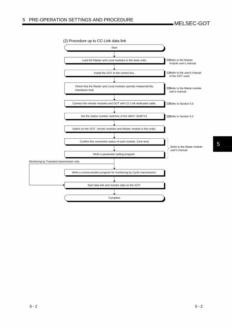
(2) Procedure up to CC-Link data link
Install the GOT to the control box.
Check that the Master and Local modules operate independently. (Hardware test)
Load the Master and Local modules to the base units.
Start
Connect the remote modules and GOT with CC-Link dedicated cable.
Set the station number switches of the A8GT-J61BT13.
Switch on the GOT, remote modules and Master module in this order.
Confirm the connection status of each module. (Line test)
Write a parameter setting program.
Write a communication program for monitoring by Cyclic transmission.
Start data link and monitor data on the GOT.
Complete
⋅⋅⋅⋅⋅Refer to the Master
Monitoring by Transient transmission only
⋅⋅⋅⋅⋅Refer to the user's manualof the GOT used
module user's manual.
⋅⋅⋅⋅⋅Refer to the Maste module user's manual.
⋅⋅⋅⋅⋅Refer to Section 5.5
⋅⋅⋅⋅⋅Refer to Section 5.2
Refer to the Maste module user's manual.
5

5 - 3 5 - 3
MELSEC-GOT5 PRE-OPERATION SETTINGS AND PROCEDURE
5.2 Names of the Parts and Their Settings
This section provides the names of the A8GT-J61BT13 parts and how to set the
switches.
21
ON
43210 F EDCBA
98765
09 8 7
65
432
10
9 8 7
65
432
10
9 8 7
65
432
1
8)
8)
5)
1) MODE
STATION NO.
BAUDRATE
SW12
ONHOLD
4
OFFCLEAR
1
DA
1 3 5 7
2 4 6 8DG NC NC
DB SLD (FG1) NC
MITSUBISHIDATALINK UNITMODEL A8GT-J61BT13
DATE
MITSUBISHI ELECTRIC CORPORATIONMADE IN JAPAN BD992C000H58
L ERR.
RD
SD
L RUN
RUN
BD999C127H01
4)
3)
2)
7)
7) 9) 7)
6)
Number Name Description
Used to set the operating status of the module. (Factory setting:0)
Number Name Description
0 Online Data link enabled and automatic return made
1 (Reserved) ———
2 Offline Disconnected from data link
3 to F (Reserved) ———
1)
Mode setting switch
432
10
F EDCBA
987
65
2)
Station number setting
switches
09 8 7
65
432
10
9 8 7
65
432
1
Used to set the station number of the A8GT-J61BT13 between 1 and 64. (Factory setting: 01)
Use " 10" to set the tens.
Use " 1" to set the units.
Used to set the transmission speed of the module. (Factory setting:0)
Number to be Set Transmission Baudrate
0 156kbps
1 625kbps
2 2.5Mbps
3 5Mbps
4 10Mbps
5 to 9Reserved (If the value you set is 5 to 9, the L.ERR
LED is lit to indicate a communication error.)
3)
Transmission baudrate
setting switch
09 8 7
65
432
1

5 - 4 5 - 4
MELSEC-GOT5 PRE-OPERATION SETTINGS AND PROCEDURE
Number Name Description
Used to set the operational conditions. (Factory setting:OFF)
Switch PositionNumber Setting Item
ON OFF
SW1 Number of occupied stations 4 stations 1 station
SW2 Input data status of faulty data link station Held Cleared
4)
Condition setting switches
21
ON
Data link status can be conformed by the on/off statuses of the LEDs.
LED Name Description
RUN LEDOn:Indicates that the module is normal.
Off:Indicates a watchdog timer error.
L RUN LEDOn:Indicates that communication is normal.
Off:Indicates a communication break (time excess error).
SD LED On:Indicates data transmission.
RD LED On:Indicates data receive.
L ERR.
LED
On: Indicates a communication data error (CRC error).
Flicker: Indicates that any switch (1 to 4) position was changed while
power is on.
Off: Indicates that communication is normal.
5)
Indicator LEDs
L ERR.
RD
SD
L RUN
RUN
6) Connector Connector for connection to the GOT
7) Module fixing screws Screws for installation to the GOT (M3 3 screw)
8)
Terminal block
DA
1 3 5 7
2 4 6 8DG NC NC
DB SLD (FG1) NC
Terminal block for cable connection (M3 8 screw)
9) Rating plate ———

5 - 5 5 - 5
MELSEC-GOT5 PRE-OPERATION SETTINGS AND PROCEDURE
5.3 Handling Instructions
Tighten the mounting and terminal screws of the A8GT-J61BT13 within the following
ranges.
Screw Location Tightening Torque Range
Module mounting screw (M3 screw) 39 to 59N•cm
Terminal block terminal screw (M3 screw) 39 to 59N•cm
Terminal block mounting screw (M3.5 screw) 59 to 88N•cm

5 - 6 5 - 6
MELSEC-GOT5 PRE-OPERATION SETTINGS AND PROCEDURE
5.4 Mounting Procedures
This section provides the procedures to mount the A8GT-J61BT13 to and from the GOT.
(1) Mounting the A8GT-J61BT13 to the GOT-A900 Series
1) Fit the communication module securing fixtures in
the GOT main unit.
2) Mount the A8GT-J61BT13 on the GOT interface.
3) Tighten and fix the mounting screws (3 pcs.) of the
communication module in the specified torque
range. (39 to 59 N•cm)
4) To remove the unit, reverse the installation
procedure.
(2) Mounting the A8GT-J61BT13 to the GOT800 Series
1) Fit the A8GT-J61BT13 to the mounting section of
the GOT.
2) Tighten the module fixing screws (3 pcs.) to within
the specified torque range (39 to 59N•cm).
3) To remove the unit, reverse the installation
procedure.
5 - 7 5 - 7
MELSEC-GOT5 PRE-OPERATION SETTINGS AND PROCEDURE
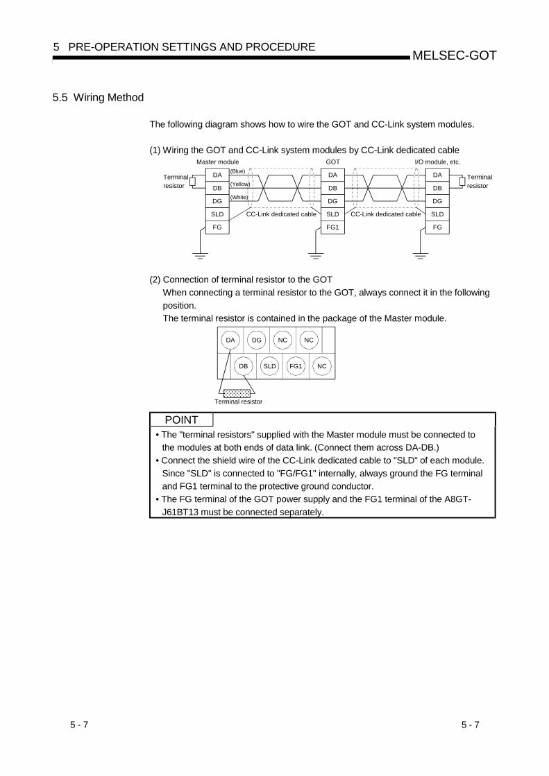
5.5 Wiring Method
The following diagram shows how to wire the GOT and CC-Link system modules.
(1) Wiring the GOT and CC-Link system modules by CC-Link dedicated cable
DA
DB
DG
SLD
FG
DA
DB
DG
SLD
FG1
DA
DB
DG
SLD
FG
Master module GOT I/O module, etc.
Terminalresistor
CC-Link dedicated cable
Terminalresistor
CC-Link dedicated cable
(Blue)
(Yellow)
(White)
(2) Connection of terminal resistor to the GOT
When connecting a terminal resistor to the GOT, always connect it in the following
position.
The terminal resistor is contained in the package of the Master module.
DA DG NC NC
DB SLD FG1 NC
Terminal resistor
��������������������������������
POINT• The "terminal resistors" supplied with the Master module must be connected to
the modules at both ends of data link. (Connect them across DA-DB.)
• Connect the shield wire of the CC-Link dedicated cable to "SLD" of each module.
Since "SLD" is connected to "FG/FG1" internally, always ground the FG terminal
and FG1 terminal to the protective ground conductor.
• The FG terminal of the GOT power supply and the FG1 terminal of the A8GT-
J61BT13 must be connected separately.

6 - 1 6 - 1
MELSEC-GOT6 PROGRAMMING
6. PROGRAMMING
The programming example described in this section is designed to make parameter
setting to the master module and communication between the GOT and remote I/O
station in the following system.
Refer to the CC-Link System Remote I/O Module User's Manual (Details) for the
remote I/O station, and to the CC-Link System Master/Local Module User's Manual
(Details) for details of the parameter setting made to the master module.
6.1 System Configuration
PLC (Q06HCPU)QJ61BT11:Station 0
CC-Link dedicated cable
A975GOT + A8GT-J61BT13Station 1:1 station occupied
AJ65BTB1-16DTStation 2:1 station occupied
6.2 Relationships Between Corresponding Devices
[QJ61BT11]Station 0
Master station
[Q06HCPU]
PLC CPU
[AJ65BTB1-16DT]Station 2:1station occupied
Remote I/O station
M0 to M15
M16 to M31
M32 to M47
M48 to M63
M112 to M127
M128 to M143
M144 to M159
M160 to M175
D100 to D103
D200 to D203
RX0F to RX00
RY0F to RY00
RWw0 to RWw3
RWr0 to RWr3
E0H
E1H
E3H
E4H
160H
161H
162H
163H
1E0H to 1E3H
2E0H to 2E3H
RX1F to RX10
RX2F to RX20
RX3F to RX30
RY1F to RY10
RY2F to RY20
RY3F to RY30
RX0F to RX00
RY0F to RY00
RX1F to RX10
RY1F to RY10
[A975GOT + A8GT-J61BT13]Station 1:1station occupied
Intelligent device station
RX0F to RX00
RY0F to RY00
RWw0 to RWw3
RWr0 to RWr3
RX1F to RX10
RX2F to RX20
RX3F to RX30
RY1F to RY10
RY2F to RY20
RY3F to RY30
Address Remote inputs (RX)Remote inputs (RX)Remote inputs (RX)
Address Remote outputs(RY)Remote outputs(RY)Remote outputs(RY)
Remote registers (RWw)Remote registers (RWw)Address
Remote registers (RWr)Remote registers (RWr)Address
6
6 - 2 6 - 2
MELSEC-GOT6 PROGRAMMING
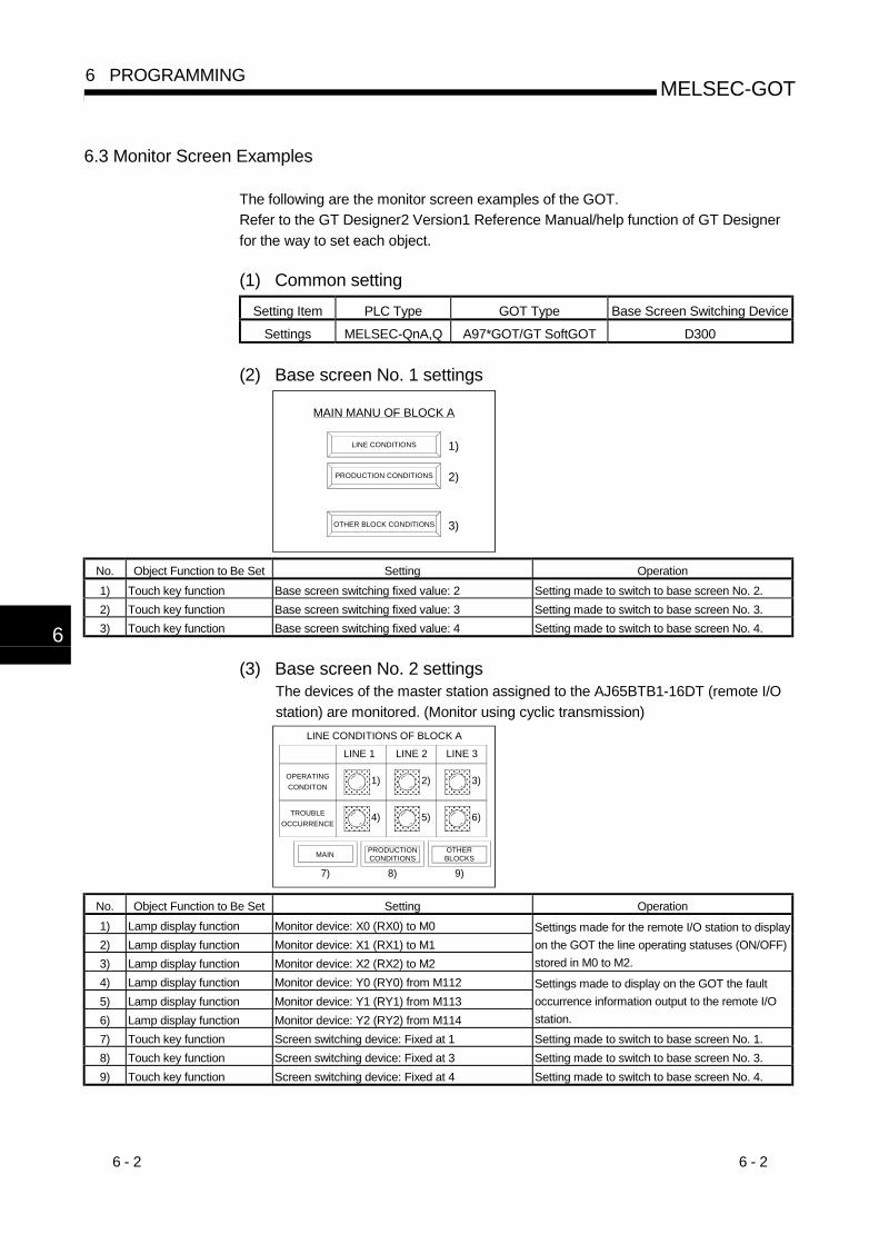
6.3 Monitor Screen Examples
The following are the monitor screen examples of the GOT.
Refer to the GT Designer2 Version1 Reference Manual/help function of GT Designer
for the way to set each object.
(1) Common setting
Setting Item PLC Type GOT Type Base Screen Switching Device
Settings MELSEC-QnA,Q A97*GOT/GT SoftGOT D300
(2) Base screen No. 1 settings
MAIN MANU OF BLOCK A
LINE CONDITIONS
PRODUCTION CONDITIONS
OTHER BLOCK CONDITIONS
1)
2)
3)
No. Object Function to Be Set Setting Operation
1) Touch key function Base screen switching fixed value: 2 Setting made to switch to base screen No. 2.
2) Touch key function Base screen switching fixed value: 3 Setting made to switch to base screen No. 3.
3) Touch key function Base screen switching fixed value: 4 Setting made to switch to base screen No. 4.
(3) Base screen No. 2 settingsThe devices of the master station assigned to the AJ65BTB1-16DT (remote I/O
station) are monitored. (Monitor using cyclic transmission)
LINE CONDITIONS OF BLOCK A
PRODUCTIONCONDITIONS
OTHERBLOCKS
1) 2) 3)
��������������������
������������������
��������������������
4) 5) 6)
��������������������
������������������
��������������������TROUBLE
OCCURRENCE
OPERATING
CONDITON
LINE 1 LINE 2 LINE 3
MAIN
7) 8) 9)
No. Object Function to Be Set Setting Operation
1) Lamp display function Monitor device: X0 (RX0) to M0
2) Lamp display function Monitor device: X1 (RX1) to M1
3) Lamp display function Monitor device: X2 (RX2) to M2
Settings made for the remote I/O station to display
on the GOT the line operating statuses (ON/OFF)
stored in M0 to M2.
4) Lamp display function Monitor device: Y0 (RY0) from M112
5) Lamp display function Monitor device: Y1 (RY1) from M113
6) Lamp display function Monitor device: Y2 (RY2) from M114
Settings made to display on the GOT the fault
occurrence information output to the remote I/O
station.
7) Touch key function Screen switching device: Fixed at 1 Setting made to switch to base screen No. 1.
8) Touch key function Screen switching device: Fixed at 3 Setting made to switch to base screen No. 3.
9) Touch key function Screen switching device: Fixed at 4 Setting made to switch to base screen No. 4.
6
6 - 3 6 - 3
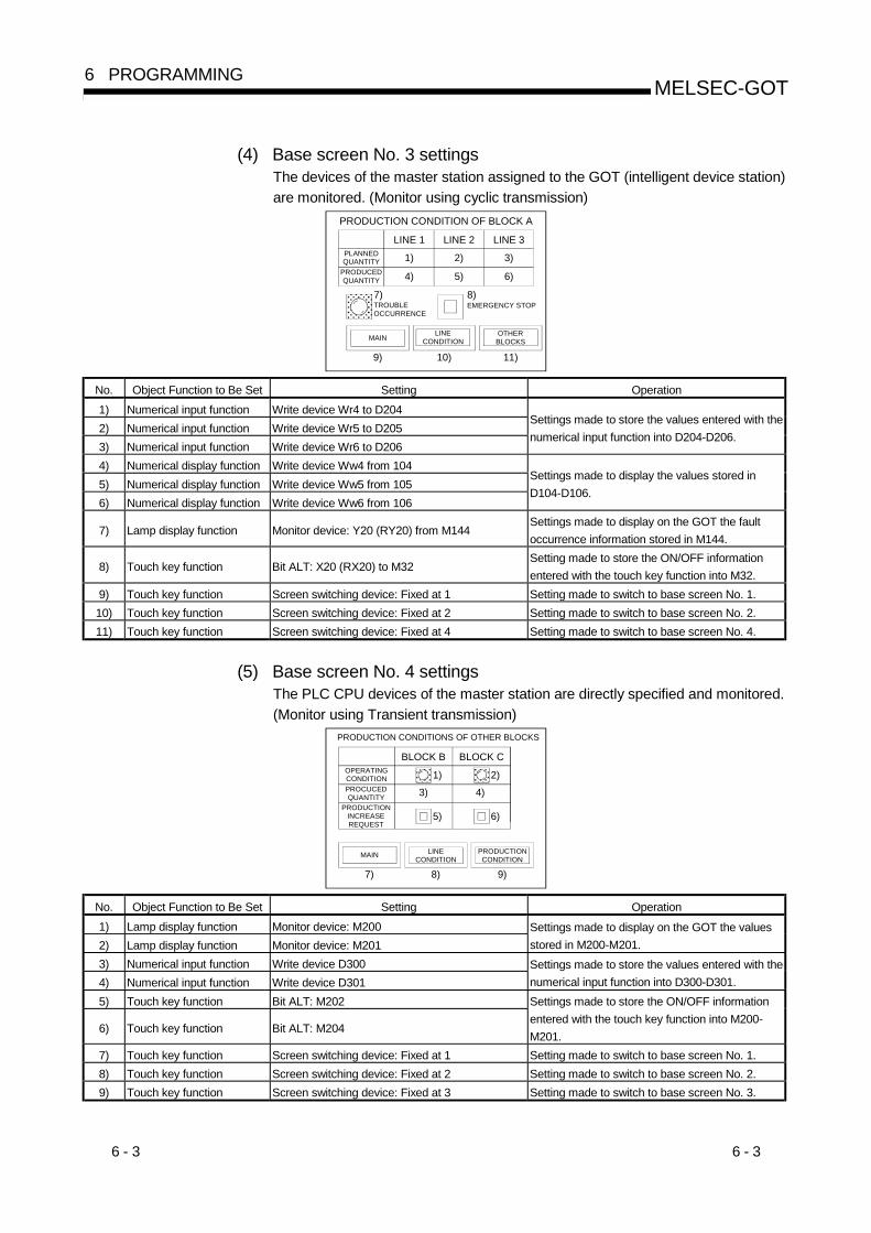
MELSEC-GOT6 PROGRAMMING
(4) Base screen No. 3 settingsThe devices of the master station assigned to the GOT (intelligent device station)
are monitored. (Monitor using cyclic transmission)
PRODUCTION CONDITION OF BLOCK A
1) 2) 3)
4) 5) 6)��������������������
PLANNEDQUANTITY
LINE 1 LINE 2 LINE 3
9) 10) 11)
PRODUCEDQUANTITY
TROUBLEOCCURRENCE
7)EMERGENCY STOP8)
LINECONDITION
OTHERBLOCKSMAIN
No. Object Function to Be Set Setting Operation
1) Numerical input function Write device Wr4 to D204
2) Numerical input function Write device Wr5 to D205
3) Numerical input function Write device Wr6 to D206
Settings made to store the values entered with the
numerical input function into D204-D206.
4) Numerical display function Write device Ww4 from 104
5) Numerical display function Write device Ww5 from 105
6) Numerical display function Write device Ww6 from 106
Settings made to display the values stored in
D104-D106.
7) Lamp display function Monitor device: Y20 (RY20) from M144Settings made to display on the GOT the fault
occurrence information stored in M144.
8) Touch key function Bit ALT: X20 (RX20) to M32Setting made to store the ON/OFF information
entered with the touch key function into M32.
9) Touch key function Screen switching device: Fixed at 1 Setting made to switch to base screen No. 1.
10) Touch key function Screen switching device: Fixed at 2 Setting made to switch to base screen No. 2.
11) Touch key function Screen switching device: Fixed at 4 Setting made to switch to base screen No. 4.
(5) Base screen No. 4 settingsThe PLC CPU devices of the master station are directly specified and monitored.
(Monitor using Transient transmission)
PRODUCTION CONDITIONS OF OTHER BLOCKS
LINECONDITION
1) 2)
3) 4)
5) 6)
OPERATINGCONDITION
BLOCK B
MAIN
7) 8) 9)
PROCUCEDQUANTITY
PRODUCTIONINCREASEREQUEST
��������������
BLOCK C������������
PRODUCTIONCONDITION
No. Object Function to Be Set Setting Operation
1) Lamp display function Monitor device: M200
2) Lamp display function Monitor device: M201
Settings made to display on the GOT the values
stored in M200-M201.
3) Numerical input function Write device D300
4) Numerical input function Write device D301
Settings made to store the values entered with the
numerical input function into D300-D301.
5) Touch key function Bit ALT: M202
6) Touch key function Bit ALT: M204
Settings made to store the ON/OFF information
entered with the touch key function into M200-
M201.
7) Touch key function Screen switching device: Fixed at 1 Setting made to switch to base screen No. 1.
8) Touch key function Screen switching device: Fixed at 2 Setting made to switch to base screen No. 2.
9) Touch key function Screen switching device: Fixed at 3 Setting made to switch to base screen No. 3.
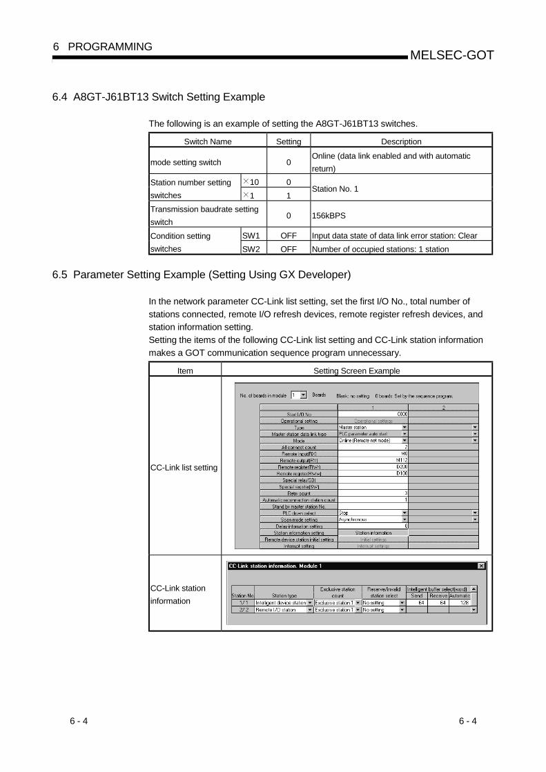
6 - 4 6 - 4
MELSEC-GOT6 PROGRAMMING
6.4 A8GT-J61BT13 Switch Setting Example
The following is an example of setting the A8GT-J61BT13 switches.
Switch Name Setting Description
mode setting switch 0Online (data link enabled and with automatic
return)
10 0Station number setting
switches 1 1Station No. 1
Transmission baudrate setting
switch0 156kBPS
SW1 OFF Input data state of data link error station: ClearCondition setting
switches SW2 OFF Number of occupied stations: 1 station
6.5 Parameter Setting Example (Setting Using GX Developer)
In the network parameter CC-Link list setting, set the first I/O No., total number of
stations connected, remote I/O refresh devices, remote register refresh devices, and
station information setting.
Setting the items of the following CC-Link list setting and CC-Link station information
makes a GOT communication sequence program unnecessary.
Item Setting Screen Example
CC-Link list setting
CC-Link station
information

7 - 1 7 - 1
MELSEC-GOT7 TROUBLESHOOTING
7. TROUBLESHOOTING
This section gives simple troubleshooting for use of the A8GT-J61BT13.
POINTBy setting the alarm list display (system alarm) function to the display screen using
the graphics software, the GOT can quickly detect a link error, in addition to the
following errors.
When a link error occurs, the following error code and error messages are
displayed in the display field of the alarm list display (system alarm) function.
Error code Message
402• Communication disable (GOT800 Series)
• Communication time-out (GOT-A900 Series)
For more details on how to set up the alarm list display (system alarm) function and
the contents of display, refer to the manuals listed in the table below.
GOT Used Manuals to refer to
GOT-A900 SeriesGT Designer2 Version1 Reference Manual/
GT Designer Help function
GOT800 SeriesSW NIW-A8GOTP Operating Manual (Monitor
Screen Creation Manual)
7.1 LED-Indicated Error Causes and Their Corrective Actions
This section explains how to check errors indicated by the LEDs of the A8GT-
J61BT13.
For errors related to the PLC CPU and Master module, refer to the user's manuals of
the PLC CPU and Master module.
(1) If the RUN LED of the A8GT-J61BT13 goes off
Cause Corrective Action
Watchdog timer error occurred.
Check the special link registers of the Master module
to make sure that the watchdog timer error occurred
and switch on power of the GOT again 1.
If the RUN LED is not lit after power is switched on
again, the hardware may be faulty. Consult your
sales representative.
Power is not supplied to the GOT or
voltage is insufficient.
Supply power to the GOT and check the voltage of
the power supply.
Switch setting is outside the specified
range (mode 2 or 4 to F, station number 0
or 65 or more, transmission speed 5 to 9).
Correct the switch setting and switch power on
again 1.
7

7 - 2 7 - 2
MELSEC-GOT7 TROUBLESHOOTING
(2) If the L RUN LED of the A8GT-J61BT13 goes off
Cause Corrective Action
CC-Link dedicated cable is broken or
shorted.Check and repair the CC-Link dedicated cable.
Master station stopped link. Check for an error at the Master station.
Station number was repeated.
Switch power on again 1 after correcting the station
number setting of the module of which station number
was repeated.
GOT parameters have not been set.Correct the GOT parameter setting and switch power of
the GOT again 1.
Power is not supplied to the GOT or
voltage is insufficient.
Supply power to the GOT and check the voltage of the
power supply.
Switch setting is outside the specified
range (mode 2 or 4 to F, station number 0
or 65 or more, transmission speed 5 to 9).
Correct the switch setting and switch power on
again 1.
(3) If the L ERR LED of the A8GT-J61BT13 flickers
Cause Corrective Action
Mode, station number or transmission
speed switch setting was changed during
normal operation.
Return the mode, station number or transmission
speed switch setting to the previous position and
switch power on again 1.
If the L RUN LED is not lit after switching power on
again, the hardware may be faulty. Consult your
sales representative.
Station number or transmission speed
switch is faulty.
If the L ERR LED begins to flicker though switch setting
was not changed during operation, the hardware may
be faulty. Consult your sales representative.
(4) If the L ERR LED of the A8GT-J61BT13 is lit
Cause Corrective Action
Switch setting is outside the specified
range (mode 2 or 4 to F, station number 0
or 65 or more, transmission speed 5 to 9).
Correct the switch setting and switch power on
again 1.
Terminal resistors are left unconnected.Check that the terminal resistors are connected. If not,
connect them and switch power on again 1.
A8GT-J61BT13 or CC-Link dedicated
cable are affected by noise.
• Connect both ends of the shield wire of the CC-Link
dedicated cable to ground (earth conductors
separately) via SLD and FG1 of each module.
• Securely connect the FG terminal of the module to
ground.
• Securely ground the piping when running cables in
piping.
1: Switch power on again:Switch power on again or turn on the reset switch.
7

7 - 3 7 - 3
MELSEC-GOT7 TROUBLESHOOTING
7.2 Communication Error Occurs between Master Station and GOT
If any repeated station number bit in any of the link special registers SW0098 to
SW009B (repeated station number status) switches on, check the GOT of the
corresponding station number in the following flowchart.
Troubleshooting flowchart used when the "ERR" LED of the Master station flickers
"ERR" LED of master station flickers
Parameter
setting match system
configuration?
Any of Masterstation link special registersSW0080 to SW0083 (other
station data link status) ON?
Any of Masterstation link special registers
SW0098 to SW009B (repeatedstation number status)
ON?
Check the module corresponding to the bit switched on.
Correct parameter settingor system configuration.
Master station faulty
Station number switch
setting correct?
Correct station number switch setting.
Switch power on again
or turn on reset switch.
Corresponding module faulty
Check the module correspondingto the bit switched on.
Power on?
"POWER" LED lit?
"RD" LED lit?
Switch power on.
Is supply voltage
within specified range?
Communication cable
wired correctly*1?
Corresponding module faulty
Corresponding module faulty
Set supply voltage towithin specified range.
Correct communication cable wiring.
To next page To next page To next page
Y
N
Y
N
Y
N
Y
N
Y
N
Y
N
Y
N
Y
N
Y
N
Master side check
GOT side check
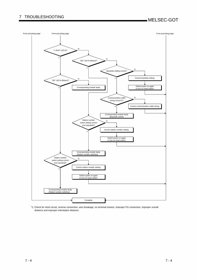
7 - 4 7 - 4
MELSEC-GOT7 TROUBLESHOOTING
Station number
switch setting correct
(not repeated)?
Correct station number setting.
"L RUN" LED lit?
"SD" LED lit (flicker)?
Communication cable
wiring correct*1?
Corresponding module faulty
Corresponding module faulty(Baudrate switch)
Correct communication cable wiring.
Y
N
Y
N
Y
Y
N
"SD" LED lit (flicker)?
Y
N
Baudrate setting correct?
Y
N
N Correct baudrate setting.
Switch power on againor turn on reset switch.
From preceding page From preceding page
Corresponding module faulty(Station number switches)
Correct station number setting.Y
N
Corresponding module faulty(Station number switches)
Station number
switch setting correct
(not repeated)?
Switch power on againor turn on reset switch.
Switch power on againor turn on reset switch.
Complete
*1: Check for short circuit, reverse connection, wire breakage, no terminal resistor, improper FG connection, improper overalldistance and improper interstation distance.
From preceding page

7 - 5 7 - 5
MELSEC-GOT7 TROUBLESHOOTING
7.3 Method for Accelerating the Data Communication Processing Speed During TransientTransmission
When monitoring is performed during transient transmission, the processing speed of
data communication can be accelerated using the following methods.
CPU types Method
When the ACPU is used
Insert a COM instruction in the sequence program of the CPU that exchanges
data with the GOT.
By inserting a COM instruction, general data request is performed between the CC-Link
module and the CPU. However, note that the scan time of the sequence program will be
extended by a maximum of about 3 ms if a COM instruction is inserted.
When the QnACPU is used
(1) Using GX Developer, select [PLC Parameters] - [PLC system] and set the
general data processing count to the same count set for the module
performing general data processing that has been mounted to the QnACPU.
(Example: If one serial communication module and one CC-Link module are
mounted, set the count to “2.”)
However, note that each time a module that performs general data processing
is added, the scan time of the sequence program will be is extended by a
maximum of about 3 ms.
Set this count to the samecount set for the module performing general data processing.
(2) Insert a COM instruction (which turns on the special relay SM775) in the
sequence program of the CPU that exchanges data with the GOT.
By inserting a COM instruction, general data request is performed between the
CC-Link module and the CPU. However, note that the scan time of the
sequence program will be extended by a maximum of about 3 ms if a COM
instruction is inserted.
When the QCPU is used
Insert a COM instruction (which turns on the special relay SM775) in the
sequence program of the CPU that exchanges data with the GOT.
By inserting a COM instruction, general data request is performed between the CC-Link
module and the CPU. However, note that the scan time of the sequence program will be
extended by a maximum of about 3 ms if a COM instruction is inserted.
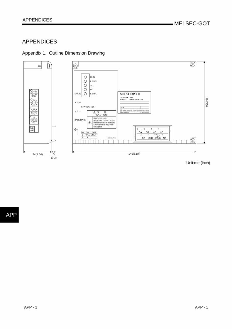
APP - 1 APP - 1
MELSEC-GOTAPPENDICES
APPENDICES
Appendix 1. Outline Dimension Drawing
21
ON
43210 F EDCBA
98765
09 8 7
65
432
10
9 8 7
65
432
10
9 8 7
65
432
1
99(3
.9)
149(5.87)34(1.34) 5(0.2)
MODE
STATION NO.
BAUDRATE
DA
1 3 5 7
2 4 6 8DG NC NC
DB SLD (FG1) NC
MITSUBISHIDATALINK UNITMODEL A8GT-J61BT13
DATE
MITSUBISHI ELECTRIC CORPORATIONMADE IN JAPAN BD992C000H58
CAUTION
Do not mount nor dismounta module while the poweris supplied.
L ERR.
RD
SD
L RUN
RUN
BD999C127H01
SW12
ONHOLD
4
OFFCLEAR
1
Unit:mm(inch)
APP

APP - 2 APP - 2
MELSEC-GOTAPPENDICES
Appendix 2. Calculating Formulas of the Transmission Delay Time When the A8GT-J61BT13 is Used
The following explains the calculating formulas of the transmission delay time when theA8GT-J61BT13 is used (when the GOT is an intelligent device station).
(1) During cyclic transmission(a) Calculating formula
SM + LS 3 + 100 (processing time of the intelligent device station: 100 ms)= Transmission delay time of the intelligent device station
SM : Scan time of the Master station’s sequence programLS : Link scan time
(b) Example of calculationWhen SM: 10 ms, LS: 5 ms10 + 5 3 + 100 = 125 (ms)
(2) During transient transmission(a) Calculating formula
MB + Processing time of the intelligent device station= Transmission delay time of the intelligent device station
1) MB = {SM + LS 2 + (request data count + 16) / 16 LS + + SM n+ LS + ((response data count + 16) / 72 LS) n + + bpsconstant} N
n: number of GOTsRequest data count: (Number of object points + (Number of object points
/ 19) 1) 6Response data count: (Number of object points + (Number of object
points / 19) 1) 22) Processing time of the intelligent device station = 90 (Number of
object points / 19) 11 Round-up
(b) Example of calculationWhen SM: 10 ms, LS: 5 ms, the numeric value display function is set to 18pointsRequest data count: 114 = (18 + (18 / 19)) 6Response data count: 38 = (18 + (18 / 19)) 2
: 0ms, : LS 5 ms, bps constant: LS 5ms 7, N: 1, n: 1
MB = {10 + 5 2 + (114 + 16) / 16 5 + 0 + 10 1+ 5 + ((38 + 16) / 72 5) 1 +5 + 5 7} 1
= 10 + 10 + 45 + 10 + 5 + 5 + 5 + 35= 125 (ms)
Processing time of the intelligent device station = 90 (Number of object points / 19)= 90 (18 / 19)= 90 (ms)
125 + 90 = 215 (ms)
Differences in the transmission delay time, depending on the number of object points(when calculated using the conditions shown above)
Number of object points set Transmission delay time
38 points 330 ms
57 points 475 ms
76 points 600 ms
95 points 735 ms
APP

Index - 1 Index - 1
INDEX
[C]Communication error occurs between master
station and GOT.............................................. 7-3
Compatible software version........................... 2-2
[D]Difference between the A8GT-J61BT13 and the
A8GT-J61BT15 ............................................... 1-2
[G]GOTs which can use the A8GT-J61BT13...... 2-2
[H]Handling instructions....................................... 5-5
How to specify devices when creating the
monitor screen................................................. 4-8
[ I ]I/O signals transferred to/from the master
module ............................................................. 4-9
[L]LED-indicated error causes and their corrective
actions.............................................................. 7-1
[M]Method for Accelerating the Data
Communication Processing Speed During
Transient Transmission................................... 7-5
Monitorable Access range .............................. 4-7
Monitoring by cyclic transmission ................... 4-1
Monitoring by transient transmission.............. 4-1
Monitor specification........................................ 4-1
Mounting procedures ...................................... 5-6
[N]Names of the parts and their settings............. 5-3
[O]Outline dimension drawing..........................App-1
[P]PLC CPU that allows monitoring .................... 1-1
Pre-operation procedure ................................. 5-1
Programming................................................... 6-1
[R]Remote register assignment ...........................4-9
[S]Setting of device names and device numbers ......4-8
Setting of NW number .....................................4-8
Setting of PLC station number ........................4-8
Specifications...................................................3-1
General specifications .....................................3-1
Performance specifications .............................3-1
System configuration .......................................2-1
Instructions for system configuration...............2-2
Overall configuration........................................2-1
[W]Wiring method..................................................5-7
Ind

Index - 2 Index - 2
MEMOInd

WARRANTY
Please confirm the following product warranty details before starting use.
1. Gratis Warranty Term and Gratis Warranty RangeIf any faults or defects (hereinafter "Failure") found to be the responsibility of Mitsubishi occurs during use of the productwithin the gratis warranty term, the product shall be repaired at no cost via the dealer or Mitsubishi Service Company.Note that if repairs are required at a site overseas, on a detached island or remote place, expenses to dispatch anengineer shall be charged for.
[Gratis Warranty Term]The gratis warranty term of the product shall be for one year after the date of purchase or delivery to a designatedplace.Note that after manufacture and shipment from Mitsubishi, the maximum distribution period shall be six (6) months, andthe longest gratis warranty term after manufacturing shall be eighteen (18) months. The gratis warranty term of repairparts shall not exceed the gratis warranty term before repairs.
[Gratis Warranty Range](1) The range shall be limited to normal use within the usage state, usage methods and usage environment, etc.,
which follow the conditions and precautions, etc., given in the instruction manual, user's manual and caution labelson the product.
(2) Even within the gratis warranty term, repairs shall be charged for in the following cases.1. Failure occurring from inappropriate storage or handling, carelessness or negligence by the user. Failure caused
by the user's hardware or software design.2. Failure caused by unapproved modifications, etc., to the product by the user.3. When the Mitsubishi product is assembled into a user's device, Failure that could have been avoided if functions
or structures, judged as necessary in the legal safety measures the user's device is subject to or as necessaryby industry standards, had been provided.
4. Failure that could have been avoided if consumable parts (battery, backlight, fuse, etc.) designated in theinstruction manual had been correctly serviced or replaced.
5. Failure caused by external irresistible forces such as fires or abnormal voltages, and Failure caused by forcemajeure such as earthquakes, lightning, wind and water damage.
6. Failure caused by reasons unpredictable by scientific technology standards at time of shipment from Mitsubishi.7. Any other failure found not to be the responsibility of Mitsubishi or the user.
2. Onerous repair term after discontinuation of production(1) Mitsubishi shall accept onerous product repairs for seven (7) years after production of the product is discontinued.
Discontinuation of production shall be notified with Mitsubishi Technical Bulletins, etc.(2) Product supply (including repair parts) is not possible after production is discontinued.
3. Overseas serviceOverseas, repairs shall be accepted by Mitsubishi's local overseas FA Center. Note that the repair conditions at each FACenter may differ.
4. Exclusion of chance loss and secondary loss from warranty liabilityRegardless of the gratis warranty term, Mitsubishi shall not be liable for compensation to damages caused by any causefound not to be the responsibility of Mitsubishi, chance losses, lost profits incurred to the user by Failures of Mitsubishiproducts, damages and secondary damages caused from special reasons regardless of Mitsubishi's expectations,compensation for accidents, and compensation for damages to products other than Mitsubishi products and other duties.
5. Changes in product specificationsThe specifications given in the catalogs, manuals or technical documents are subject to change without prior notice.
6. Product application(1) In using the Mitsubishi MELSEC programmable logic controller, the usage conditions shall be that the application will
not lead to a major accident even if any problem or fault should occur in the programmable logic controller device, andthat backup and fail-safe functions are systematically provided outside of the device for any problem or fault.
(2) The Mitsubishi general-purpose programmable logic controller has been designed and manufactured for applicationsin general industries, etc. Thus, applications in which the public could be affected such as in nuclear power plants andother power plants operated by respective power companies, and applications in which a special quality assurancesystem is required, such as for Railway companies or National Defense purposes shall be excluded from theprogrammable logic controller applications.Note that even with these applications, if the user approves that the application is to be limited and a special quality isnot required, application shall be possible.When considering use in aircraft, medical applications, railways, incineration and fuel devices, manned transportdevices, equipment for recreation and amusement, and safety devices, in which human life or assets could be greatlyaffected and for which a particularly high reliability is required in terms of safety and control system, please consultwith Mitsubishi and discuss the required specifications.
User,s ManualUser,s Manual
Mitsubishi Graphic Operation Terminal
MODEL
MODELCODE
A8GT-J61BT13-U-E
1DM072
IB(NA)-66838-D(0406)MEE
A8GT-J61BT13 Type CC-Link Communication ModuleA8GT-J61BT13 Type CC-Link Communication Module
Specifications subject to change without notice.
When exported from Japan, this manual does not require application to theMinistry of Economy, Trade and Industry for service transaction permission.
HEAD OFFICE : 1-8-12, OFFICE TOWER Z 14F HARUMI CHUO-KU 104-6212,JAPANNAGOYA WORKS : 1-14 , YADA-MINAMI 5-CHOME , HIGASHI-KU, NAGOYA , JAPAN